Embed Size (px)
Citation preview

HTC confidential © 2001, HTC Corporation. All rights reserved. TOTAL 58 CONT.ON. 2 PAGE NO. 1
Service Manual for XDA
HTC Proprietary Confidential Treatment Requested
Rev. 2.3 August 07, 2003
HTC Corp. Engineering Mobility

HTC confidential © 2001, HTC Corporation. All rights reserved. TOTAL 58 CONT.ON. 3 PAGE NO. 2
TITLE: Service Manual for XDA REV. NO.
DATE CONTENTS DEP. REVISED APP´D STGE.PER.
0.1 Feb. 08,
2002 Fist Draft
Technical Support
Carlos Lee
1.0 Mar. 01,
2002
First Release
OEM Product
Sustaining
Carlos Lee
1.1
May. 01, 2002
Update mechanical parts OEM Product
Sustaining
Carlos Lee
2.0
Jun. 20, 2002
Update Accessories P/N and Troubleshooting
OEM Product
Sustaining
Carlos Lee
2.1 Oct. 17, 2002
Update 64MB P/N TSE James Kao
2.2 Nov. 11, 2002
Add spare parts P/N TSE James Kao
2.3
Aug. 07, 2003
Update appendix
TSE
Felix Lu

HTC confidential © 2001, HTC Corporation. All rights reserved. TOTAL 58 CONT.ON. 4 PAGE NO. 3
Table of contents 1. INTRODUCTION ··········································································································4
2. PRODUCT SPECIFICATIONS ·····················································································4
2.1 PRODUCT CONFIGURATION···············································································4
2.2 SPECIFICATIONS OF XDA··················································································5
2.3 SPECIFICATIONS OF EARPHONE HEADSET WITH REMOTE ···································7
2.4 SPECIFICATIONS OF AC ADAPTER ·····································································7
3. SYSTEM BLOCK DIAGRAM·······················································································8
4. SERVICING TOOLS ····································································································9
5. ASSEMBLING AND DISASSEMBLING ······································································10
5.1 DISASSEMBLING ·····························································································10
5.2 ASSEMBLING··································································································20
6. PROBLEM DIAGNOSTICS ························································································25
6.1 LIST OF TEST JIGS··························································································25
6.2 CLASSIFICATION OF NON CONFORMITY ···························································26
6.3 TROUBLESHOOTING AND REPAIR·····································································27
7. DIAGNOSTIC PROGRAMS ·······················································································34
7.1 LIST OF TEST ITEMS (BUILT-IN DIAGNOSTICS)··················································34
7.2 TEST ITEMS OPERATION ·················································································34
8. SPARE PARTS LIST & EXPLODED DIAGRAMS······················································36
8.1 LIST OF SPEAR PARTS····················································································36
8.2 EXPLODED DIAGRAMS ····················································································37
APPENDIX·····················································································································38
A. CUSTOMER, RETAILER MISJUDGMENT·······························································38
B. REPAIR TROUBLE SHOOTING GUIDE··································································40
C. WINCE & GSM FIRMWARE REFLASH PROCEDURE ··········································41
D. TALK TIME CLEAR PROCEDURE(FOR REFURBISHMENT ONLY) ···························51
E. CLEAR PERMANENT SAVE(FOR REFURBISHMENT ONLY)····································55
F. BATTERY RUNDOWN TESTING PROCEDURE ························································57

HTC confidential © 2001, HTC Corporation. All rights reserved. TOTAL 58 CONT.ON. 5 PAGE NO. 4
1. Introduction
This manual provides the technical information to support the service activities of the XDA.
This document contains highly confidential information, so any or all of this document should not be revealed to any third party.
2. Product Specifications
2.1 Product Configuration Standard Package
Model name HTC Part Number Customer Part Number Description
Main Unit (XDA) 80H00085-50
USB Cradle 80H00090-00
Stylus 74H00083-00
AC Adapter 79H00016-00
UK Plug /AC Adapter 79H00019-10
EU Plug /AC Adapter 79H00019-20
Australia Plug /AC
Adapter 79H00019-30
DC Jack Converter 75H00146-01
Pouch, Leather Case 70H00012-00
Service Kit 93H00013-00 (ENG)
93H00013-01 (Australia)
93H00013-10 (GER)
Microsoft ActiveSync3.5,
Outlook2002
Quick Start Guide 91H00136-00 (ENG)
91H00136-10 (GER)
User’s Manual 91H00135-00 (ENG)
91H00135-10 (GER)
Warning Flyer 91H00153-00 (ENG)
91H00153-10 (GER)
91H00153-20 (NL)
Warranty Card 91H00177-00 (ENG)
91H00177-01 (Australia)
91H00177-10 (Asia)

HTC confidential © 2001, HTC Corporation. All rights reserved. TOTAL 58 CONT.ON. 6 PAGE NO. 5
2.2 Specifications of XDA
Item Specification Platform • Windows CE with Merlin OS - English, French,
German, Italian, Spanish • Combined GSM/GPRS and PDA. • 2 logical block (PDA and GSM/GPRS) solution,
layout is integrated into one module • GSM/GPRS can be turned off to let PDA to run
alone Outside Dimensions 72.7(W) x 17.8(D) x 129.0 (H) mm (3 in. x 0.7 in. x 4.9
in.) Volume 140cc
Weight 186.5g Operating conditions Temperature: 0℃to 40℃, Humidity: 90% RH
• Temperature capable of charging: 5℃ to 35℃(41℉ to 95℉) (According to the operating status, the charging may pause even when the ambient temperature is below 35℃(95℉).)
Type Rechargeable Li-Ion Polymer Battery Built-in battery
Continuing operating time
Approx. 7 hrs with a minimum communication time of 2.5 hrs (voice call continuously, PDA off while voice call, LCM off, at nominal RF Tx. Power level 29dBm, 50% of speech of running time) Standby: 100 hrs
Memory keeping time Approx. 30 hours If left at ambient temperature of 25℃ (77℉)after the power has become unable to turn on. Note: Continuing operating time and memory keeping time vary according to the charging condition, ambient temperature, operating condition, etc.
GSM/GPRS Functional Block GSM Dual band E-GSM900- 880-915, 925-960MHz
GSM1800-1710-1785, 1805-1880MHz

HTC confidential © 2001, HTC Corporation. All rights reserved. TOTAL 58 CONT.ON. 7 PAGE NO. 6
Memory Combo Flash ROM (4MB) and SRAM (512KB) SIM 3V SIM Operation WAP/HTML MS Pocket IE browser GPRS GPRS Class B,
Multislot class 8 (4R1T) WAP over GPRS Encryption GEA1&2 support GPRS indicator
PDA Functional Block Processor Strong ARM SA-1110 Clock frequency 206MHz Memory (RAM) 64/32MB SDRAM
32-bits data bus, SyncDRAM. 64/32MB for Standard Device.
Display High Reflective color TFT, 240x320 pixels, 4,096 colors Wireless Antenna
GSM/GPRS Plug in SIM card SD card slot Possible to insert SD memory card or MMC card Infrared port Infrared IrDA SIR X1 Stereo headphone
Ø2.5mm, stereo mini plug with Microphone and Phone pick up button, volume adjust are also included.
Interface
Cradle connection port
Cradle combo connector (22pin)- Serial, USB Slave, power signals and Audio (support Car kit)
AC adapter INPUT: 100-240V AC, 0.2A, 50-60Hz OUTPUT: 5V DC, 1A typical

HTC confidential © 2001, HTC Corporation. All rights reserved. TOTAL 58 CONT.ON. 8 PAGE NO. 7
2.3 Specifications of Earphone Headset with Microphone
Item Specifications Description Pick up Phone / Mute
Button module with built-in MIC.
Press to pick up incoming call. Or press to Mute during conversation.
Headset Volume Volume up and down Plug DIA 2.5mm 4 Poles Jack Cable length Approx. 110 cm Distance from Plug to Pick
up Phone / Mute unit.
2.4 Specifications of AC Adapter
Item Specifications Description
Input rated voltage
AC 100 – 240 (V)
Input power 20 (W) Input frequency 50 / 60 (Hz) Output voltage 5 (VDC) Tolerance is +/- 5% Output current 1.0 (ADC) Max.
HTC confidential © 2001, HTC Corporation. All rights reserved. TOTAL 58 CONT.ON. 9 PAGE NO. 8
3. System Block Diagram

HTC confidential © 2001, HTC Corporation. All rights reserved. TOTAL 58 CONT.ON. 10 PAGE NO. 9
4. Servicing Tools
This chapter provides information for the servicing tools for XDA. List of Servicing Tools
No. Item Use Remark 1 USB or Serial Cradle Check for Cradle I/F (Serial
communication only)
2 USB DATA interface Cable Check for Cradle I/F (USB communication only)
3 Special Made Plastic Stick Disassembling for XDA 4 SD Memory Card For SD card test 5 Earphone Headset For Audio test. 6 AC Adapter Power supply to XDA.

HTC confidential © 2001, HTC Corporation. All rights reserved. TOTAL 58 CONT.ON. 11 PAGE NO. 10
5. Assembling and Disassembling
5.1 Disassembling
Tools needed for Assembling and Disassembling
the XDA 1. Lens Cleaning Tissue.
2. Flat Screw Driver 2.4mm
3. Philip Screw Driver #0.
4. Torex Screw Driver T6X40
5. Special Made Plastic Stick.
6. Tweezers.
Remove the Stylus, SD Card slot Filler, and the Audio Jack Rubber Insert.
Next, check where SIM Card compartment in case the SIM Card has been left inside. To remove the SIM Card, use the Stylus to open de door as indicated in the picture.
Push the SIM Card Lock Release with the Stylus in the location shown in the picture to eject the SIM Card.

HTC confidential © 2001, HTC Corporation. All rights reserved. TOTAL 58 CONT.ON. 12 PAGE NO. 11
The SIM Card will be ejected and then extract the card.
The Stylus is equipped with a Reset Pin. Turn the plastic part to release from Stylus.
Before attempting to disassemble the unit, Please make sure that the main battery switch has been switched OFF, AC adapter has been disconnected. To switch OFF the battery, refer to the right lower side of the unit, using the Stylus Rest Pin, slightly push the pin into the hole as indicated on the left. Push The Main Battery Switch ONCE to switch it ON; push it once again to switch it OFF.

HTC confidential © 2001, HTC Corporation. All rights reserved. TOTAL 58 CONT.ON. 13 PAGE NO. 12
To open de case, remove 4 screws at the rear side of the unit. Note that there is 2 types of screws are used. The Upper two screws are Standoff type with flat slot. (72H30051-00). The Lower two screws are Torex type screws. (72H30052-00).
Once the 4 screws have been removed from the Back Housing, Use the Plastic Tool to open the housing. Insert and gently twist into the gap at the between upper and lower case with the FLAT side of the tool.
Start this action on the left lower corner of the unit. Note that the force applied is toward the Front side direction.

HTC confidential © 2001, HTC Corporation. All rights reserved. TOTAL 58 CONT.ON. 14 PAGE NO. 13
Once the first hook has been released, use the Plastic Tool, slide the tip of tool along the gap of the unit to unlock the rest of the hooks.
Then, for the other side of the unit, also start it at the point near the cradle connector.
Squeeze it in the direction shown here and slide it toward the left side.
Continue sliding the plastic tools along the unit’s border line and stop before the antenna.

HTC confidential © 2001, HTC Corporation. All rights reserved. TOTAL 58 CONT.ON. 15 PAGE NO. 14
After ALL the hooks around the perimeter of the unit, open the Rear Housing of the unit as shown in the picture.
AT this stage, if the defect part corresponds to the Main Board or LCD and Front Panel, please continue disassembling the Module on the left. If the problem resides in Battery Pack, Vibrator, or Back Housing.
Next, remove the 3 Flexible Cables from the Main
Board, the LCD PFC, Touch Panel FPC, and Front
Light FPC.
For LCD PFC, use your finger to lift the connector
lock upwards from both ends at the same time as
indicated in the picture. The angle must not
exceed 90 degrees.
Additional practices need to be explained

HTC confid © 2001, HT All rights reserved. TOTAL 58 CONT.ON. 16 PAGE NO. 15
ential C Corporation.
Next, to remove the Touch Panel FPC, unlock the connector lock with a tweezers.
Then, gently pull out the Touch Panel FPC with the tweezers as indicated in the picture. Repeat the same procedure to remove the Front Light FPC which is located next to the Touch Panel Connector.
To remove the Main Board, unfasten two Philip
type screws (72H30026-00) from upper right
corner and lower left corner of the Main Board.
Then remove the Main Board by holding the front panel first and lift the MB by the Antenna as shown in the picture.

HTC confidential © 2001, HTC Corporation. All rights reserved. TOTAL 58 CONT.ON. 17 PAGE NO. 16
This rubber acoustic cushion is very easy to be
left (forgotten) on the M/B. it must be removed
and installed to the new board if it is changed.
If the Main Board has to be replaced, remove
the Antenna by pulling it out as straight as
possible in the direction indicated in the picture.
Note: There’s a black spacer rubber cushion
marked in the red circle. Remember to place a
new one on the new M/B in the exact same
location.
The P/N for this spacer rubber is 76H00239-00.
Please make sure the orientation of the rubber is
indicated in the exact location next to the RF
Switch. Remember to place this rubber on the New
Main board.
ON THE OTHER SIDE of the M/B, there’s a
transparent mylar 76H00228-00, it should also be
placed on the New Main board on top of the other
spacer rubber, 76H00230-00.
© 2001, HT served. TOTAL 58 CONT.ON. 18 PAGE NO. 17
HTC confidential C Corporation. All rights re
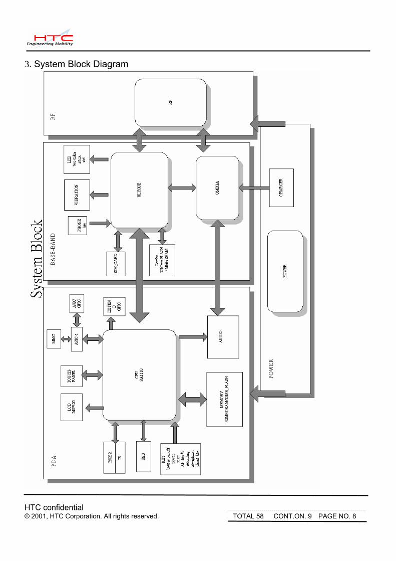
Be careful not to press the red dotted area, the SD
Card socket. Same for all other metallic shielding.
The Navigation Button has to be removed, too.
Then the Main Board is ready to be replaced.
If the Vibrator needs to be replaced, or the Back housing will be changed, remember to remove the Vibrator assembly from the Back Housing.
If the Battery Pack has to be replaced, inter the Flat-end of the plastic tool between the battery pack and the Back Housing, then gently twist the tool straight in the central area beneath the battery pack gently until its top end then lift it upwards slowly.

HTC confidential © 2001, HTC Corporation. All rights reserved. TOTAL 58 CONT.ON. 19 PAGE NO. 18
To Disassemble the LCD Module
Unfasten 4 screws (72H30026-00) from the locations on the LCD Module as shown in the picture.
To remove the metal brackets
Once the screws are removed, there’re two metal brackets should be removed. One is longer, the top bracket 72H00173-00; the shorter is bottom bracket 72H00135-00.
Hold the entire assembly as seen in the picture and push the LCD Panel from the front side to remove the LCD Module.
HTC confidential © 2001, HTC Corporation. All rights reserved. TOTAL 58 CONT.ON. 20 PAGE NO. 19
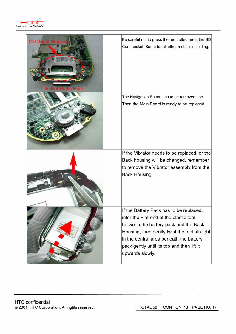
If the Speaker or Microphone, or the FrontBezel need to be replaced, go to next page to continue
If the Speaker is defective, remove it directly from the Bezel.
Be reminded there’s a Rubber Seal on the top and bottom of the Speaker module, both of these Seals should be installed correctly to prevent acoustic problems.
If the MIC has to be replaced, just take it out as shown in the picture. Note that there’s also a rubber seal under it.
The disassembly procedure is finished.
HTC confidential © 2001, HTC Corporation. All rights reserved. TOTAL 58 CONT.ON. 21 PAGE NO. 20
5.2 Assembling
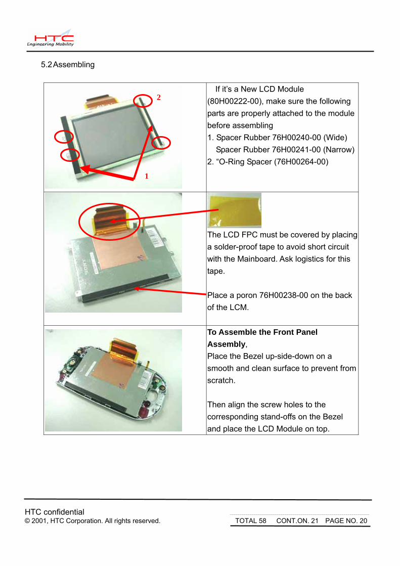
If it’s a New LCD Module (80H00222-00), make sure the following parts are properly attached to the module before assembling 1. Spacer Rubber 76H00240-00 (Wide)
Spacer Rubber 76H00241-00 (Narrow)2. “O-Ring Spacer (76H00264-00)
The LCD FPC must be covered by placing a solder-proof tape to avoid short circuit with the Mainboard. Ask logistics for this tape. Place a poron 76H00238-00 on the back of the LCM.
To Assemble the Front Panel Assembly, Place the Bezel up-side-down on a smooth and clean surface to prevent from scratch. Then align the screw holes to the corresponding stand-offs on the Bezel and place the LCD Module on top.
2
1

HTC confidential © 2001, HTC Corporation. All rights reserved. TOTAL 58 CONT.ON. 22 PAGE NO. 21
Place the metal brackets in the corresponding location and fasten 4 screws. Screw Torque: 0.9±0.1 kgw/m²
If the Microphone is being replaced. Please check the following. 1. The presence of the black rubber
Cushion 76H00223-00. 2. Then install the microphone in place.
Place the navigation button on the Mainboard
Note that the button has two pins, these pins
must be facing up to the top of the PDA. The
correct installation should look as the top picture
on the left.
This is the SIM Door Switch on the Main Board,
Pay special attention not to damage this switch
while handling the Main Board.
The IMEI number label is located on top of Main
Board as indicated on the left. It is also found in
the unit by tapping Start Settings System
Device Information Identity. This number
should be printed in the new label. Keep the
Serial Number and Part Number the same.
1 2
Pins

HTC confidential © 2001, HTC Corporation. All rights reserved. TOTAL 58 CONT.ON. 23 PAGE NO. 22
Insert the Antenna onto the Main Board. Keep in mind the correct orientation of the Antenna.
Install the speaker on the front panel. Important Note: The speaker must be placed in the direction as shown in the picture. The Left Contact terminal should look as a “C” mark. Then check the MIC.
To assemble the Main Board, place the Main Board fasten two Philip type screws (72H30026-00) from upper right corner and lower left corner of the Main Board. Screw Torque: 0.9±0.1 kgw/m² After that place a Tamper Proof Label on the upper screw head.
Then insert the LCD FPC into the connector and lock it by pressing the brown bar down.

HTC confidential © 2001, HTC Corporation. All rights reserved. TOTAL 58 CONT.ON. 24 PAGE NO. 23
Next, insert the Touch Panel FPC with the help of a tweezers.
1. Make sure the connector is unlocked.
2. Align and insert the FPC properly.
Push the connector lock to fix the Touch panel FPC. It is much easier to do it with the finger. Repeat same procedure to connect Front Light FPC
When inserting the Front light FPC, make sure to fully insert it completely to the end To assure the proper contact. For easy insertion, insert with an angle of 45 degrees.
Next, Close the Front Bezel and Back Housing starting from the top edge of the unit.

HTC confidential © 2001, HTC Corporation. All rights reserved. TOTAL 58 CONT.ON. 25 PAGE NO. 24
Then Close the entire Housing and Press the
upper and lower housing along the edge of the
unit.
Repeat the procedure to close the rest of the gaps Gently press both housings. Be careful not to press on the LCD panel area.
Then, fasten 4 screws at the rear side of the unit. Note that there is 2 types of screws are used. The Upper two screws are Standoff type with flat slot. (72H30051-00). The Lower two screws are Torex type screws. (72H30052-00).
Screw Torque: 1.2±0.1 kgw/m²

HTC confidential © 2001, HTC Corporation. All rights reserved. TOTAL 58 CONT.ON. 26 PAGE NO. 25
The Unit now is ready for Function Test and RF Test. Once passed all the test, If M/B was replaced, the Regulation Label on the unit should be printed with the new IMEI number. Find it in the unit: Start Settings System Device Information Identity.
Note that in the lower right corner of the label, there’s a 3-digit code, it should be also printed and kept the same as before the repair.
The Unit Assembly is done ready for further tests. 6. Problem Diagnostics
6.1. List of Test Jigs
Item Name Usage Remark
RS-232 Serial Cable For data port test
USB Cable For data port test
Special Plastic Tool For unit disassembly
AC Adapter For battery recharge and power related tests
Earphone with Microphone For audio test
SD Card or MMC Card For write protect, read and write test
<Hardware Requirement for PC>
O.S.: Windows 98/ME/2000 CPU: Pentium 166MHz or above Memory: 64MB PC Link: ActiveSync 3.5
HTC co© 2001,
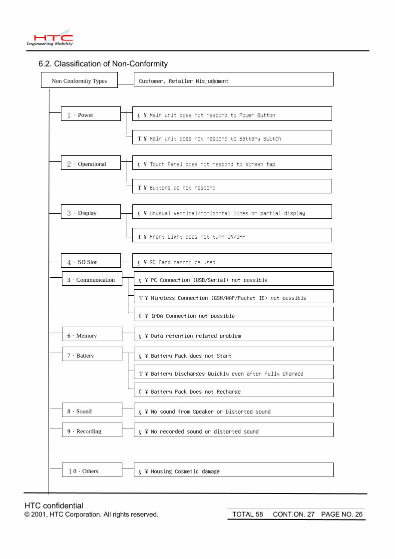
6.2. Classification of Non-Conformity
s Customer, Retailer Misjudgment
Non Conformity Typenfidential
HTC Corporation. All rights reserved. TOTAL 58 CONT.ON. 27 PAGE NO. 26
A.Main unit does not respond to Power Button
A.Touch Panel does not respond to screen tap
1.Power
2.Operational
B.Buttons do not respond
3.Display A.Unusual vertical/horizontal lines or partial display
B.Front Light does not turn ON/OFF
5.Communication A.PC Connection (USB/Serial) not possible
A.Data retention related problem6.Memory
B.Battery Discharges Quickly even after fully charged
7.Battery
8.Sound A.No sound from Speaker or Distorted sound
A.SD Card cannot be used4.SD Slot
B.Main unit does not respond to Battery Switch
B.Wireless Connection (GSM/WAP/Pocket IE) not possible
C.IrDA Connection not possible
C.Battery Pack Does not Recharge
9.Recording A.No recorded sound or distorted sound
10.Others A.Housing Cosmetic damage
A.Battery Pack does not Start

HTC confidential © 2001, HTC Corporation. All rights reserved. TOTAL 58 CONT.ON. 28 PAGE NO. 27
6.3 Troubleshooting & Repair Before attempting to Diagnose the unit received for repair, perform a Full Reset (Cold Boot) in advance.
1-A.Main Unit Does Not Respond to Power Button 1-B.Main Unit Does Not Respond to Battery Switch
(1) Make sure the Battery Switch is correctly pushed to activate the battery pack.
(2) Make sure the SIM Door is closed properly. If the door is damages, replace the back housing.
(3) Connect the AC Adapter, maybe the built-in battery pack is exhaust.
(4) Dismantle the Main Unit and check whether battery pack is correctly assembled.
(5) Check the Power Button & Battery Switch.
(6) Try with another battery pack.
(7) Replace battery pack if necessary.
(8) Check all connections including LCD FPC to Main Board. Try with another Main Board.
(9) Replace Main Board if necessary.
(10) Once the defective part has been identified, verify it again with the defective part whether the
symptom could be duplicated.
2-A.Touch Panel Does Not Respond to Screen Tap
(1) Dismantle the unit, check the perimeter of Display between Front Bezel and Touch Pane
surface for unusual foreign objects. Clean it, reassemble the unit and check the panel’s
function again.
(2) Check the connection of Touch Panel FPC whether is properly connected.
(3) Try with another LCM.
(4) Try with another Main Board.
(5) Replace LCM if necessary
(6) Replace Main Board if necessary.
(7) Once the defective part has been identified, verify it again with the defective part whether the
symptom could be duplicated.
HTC confidential © 2001, HTC Corporation. All rights reserved. TOTAL 58 CONT.ON. 29 PAGE NO. 28
2-B.Buttons Do Not Respond
(1) Dismantle the unit, check the status of switches on the Main Board and the plastic parts of
button of the Button not responding.
(2) Try with another Main Board or Front Bezel.
(3) Replace Main Board or Front Bezel if necessary.
(4) Once the defective part has been identified, verify it again with the defective part whether
the symptom could be duplicated.
3-A.Unusual Vertical / Horizontal lines or partial display
(1) Check the connection of LCM FPC whether is properly connected.
(2) Try with another LCM.
(3) Try with another Main Board.
(4) Replace LCM if necessary
(5) Replace Main Board if necessary.
(6) Once the defective part has been identified, verify it again with the defective part whether the
symptom could be duplicated.
3-B.Front Light Does Not Turn ON/OFF
(1) Check the connection of Front Light FPC whether is properly connected.
(2) Try with another LCM.
(3) Try with another Main Board.
(4) Replace LCM if necessary
(5) Replace Main Board if necessary.
(6) Once the defective part has been identified, verify it again with the defective part whether the
symptom could be duplicated.
4-A.SD Card cannot be used
(1) Check whether SD or MMC Card is fully inserted to the slot until you hear a click.
(2) Try with another SD / MMC Card and Check whether it is Write Protected.
(3) Try with another Main Board.

HTC confidential © 2001, HTC Corporation. All rights reserved. TOTAL 58 CONT.ON. 30 PAGE NO. 29
(4) Replace Main Board if necessary.
(5) Once the defective part has been identified, verify it again with the defective part whether the
symptom could be duplicated.
5-A.PC Connection (USB / Serial) not possible
(1) Check whether “Connection Settings” in the MS ActiveSync is properly set.
(2) Check whether it connects with other cables or cradle, customer’s cable might be damaged.
(3) Check the external appearance of the connector on the unit whether it is physically damaged.
(4) Replace Main Board if necessary.
(5) Once the defective part has been identified, verify it again with the defective part whether the
symptom could be duplicated. 5-B.Wireless Connection (GSM / WAP / GPRS) not possible
(1) Make sure the user has been contacting the Carrier for SIM Card validation and activation.
(2) Make sure the Wireless Connection Settings has been properly set.
(3) Make sure the SIM Card is properly inserted to the SIM compartment. Make a life call or test
it with the RF Test Station (Antenna Test).
(4) Dismantle the Main Unit and check whether the Antenna is properly installed.
(5) Try with another Antenna.
(6) Try with another Main Board if necessary.
(7) Once the defective part has been identified, verify it again with the defective part whether the
symptom could be duplicated.
5-C.IrDA Connection not possible
(1) Make sure the IrDA port settings on the Notebook or PC are properly set.
(2) Make sure the IrDA function is properly activated on the Pocket PC and on the other device.
(3) Make sure there’s no obstruction between the two devices in connection and within the distance.
(4) Check the IrDA window whether it is broken or cracked. Replace Front Bezel if necessary.
(5) Replace Main Board if necessary.
(6) Once the defective part has been identified, verify it again with the defective part whether the
symptom could be duplicated.

HTC confidential © 2001, HTC Corporation. All rights reserved. TOTAL 58 CONT.ON. 31 PAGE NO. 30
6-A.Data Retention related problem
(1) Data introduced by User might be lost when Battery has drained completely.
(2) Ask user to charge the Main Unit when latest warning message pops up.
(3) Ask users to back up their data to the PC or SD card when expect stop using the unit for long
period of time, for example, more than one week.
(4) Charge the Main Unit and check if data looses even the Battery pack is charged or at least
The unit still can be powered on without AC Adapter.
(5) Check whether AC Adapter is functioning properly.
(6) Check whether the condition of Battery Charging status is correct.
(7) Dismantle the unit and check the appearance of Battery Pack.
(8) Replace Battery Pack if necessary
(9) Replace Main Board if necessary.
(10) Once the defective part has been identified, verify it again with the defective part whether the
symptom could be duplicated.
7-A.Battery Pack does not start
(1) Make sure the SIM Door is closed properly. If the door is damages, replace the back
housing. Data introduced by User might be lost when Battery has drained completely.
(2) Connect to the AC Adapter and see if it takes charge. Also check AC Adapter condition.
(3) Ask users to back up their data to the PC or SD card when expect stop using the unit for long
period of time, for example, more than one week.
(4) Charge the Main Unit and check if data looses even the Battery pack is charged or at least
The unit still can be powered on without AC Adapter.
(5) Check whether AC Adapter is functioning properly.
(6) Check whether the condition of Battery Charging status is correct.
(7) Dismantle the unit and check the appearance of Battery Pack.
(8) Try with another Battery Pack or Replace Battery Pack if necessary
(9) Try with another Main Board or Replace Main Board if necessary.
(10) Once the defective part has been identified, verify it again with the defective part whether the
symptom could be duplicated.
.

HTC confidential © 2001, HTC Corporation. All rights reserved. TOTAL 58 CONT.ON. 32 PAGE NO. 31
7-B.Battery discharges quickly even after fully charged
(1) Make sure the Battery Pack takes fully charge with AC Adapter.
(2) Check whether the condition of Battery Charging status is correct.
(3) Dismantle the unit and check the appearance of Battery Pack.
(4) Try with another Battery Pack or Replace Battery Pack if necessary
(5) Try with another Main Board or Replace Main Board if necessary.
(6) Once the defective part has been identified, verify it again with the defective part whether the
symptom could be duplicated.
7-C.Battery Pack does not recharge
(1) Make sure the Battery Pack takes fully charge with AC Adapter.
(2) Check whether the condition of Battery Charging status is correct. Charge should be done
in no more than 3 hours.
(3) Dismantle the unit and check the appearance of Battery Pack.
(4) Try with another Battery Pack or Replace Battery Pack if necessary
(5) Try with another Main Board or Replace Main Board if necessary.
(6) Once the defective part has been identified, verify it again with the defective part whether the
symptom could be duplicated.
8-A.No Sound from Speaker or Distorted sound
(1) Check “Sound & Notifications” Settings in the unit for Sound Enabling.
(2) Make sure it’s not MUTED.
(3) Dismantle and Check whether the Speaker is properly installed (Orientation)
(4) Replace Speaker if necessary.
(5) Replace Main Board if necessary.
(6) Once the defective part has been identified, verify it again with the defective part whether the
symptom could be duplicated.
9-A.No Recorded Sound or Distorted sound
(1) Check “Sound & Notifications” Settings in the unit for Sound Enabling.

HTC confidential © 2001, HTC Corporation. All rights reserved. TOTAL 58 CONT.ON. 33 PAGE NO. 32
(2) Make sure it’s not MUTED.
(3) Dismantle and Check whether the Microphone is properly installed (check or missing rubber)
(4) Replace Microphone if necessary.
(5) Replace Main Board if necessary.
(6) Once the defective part has been identified, verify it again with the defective part whether the
symptom could be duplicated.
10-A.Housing Cosmetic damage
(1) Unless it is for Refurbishment, all housing replacement due to cosmetic damage shall be
subject to be charged.

HTC confidential © 2001, HTC Corporation. All rights reserved. TOTAL 58 CONT.ON. 34 PAGE NO. 33
7. Diagnostic Program 7.1. List of Test Items (built-in Diagnostics)
No. Item Description Remark 1 Auto Test N/A 2 RAM Test RAM Check Size/Write/Read/Comparison test. 3 Display Test Test the LCD display quality. 4 Touch Test Touch screen alignment test. Suggest to test in WinCE 5 Playback Test Play sound with 8KHz|44.1KHz sample rates. 6 Record Test Record audio sound and playback it. 7 Button Test Test every most of button. 8 Checksum Test 9 USB Test Suggest to test in Windows CE 10 Sir Test Suggest to test in Windows CE 11 Series Test Suggest to test in Windows CE 12 F Light Test Front light ON with in different brightness level. 13 LED Test Test the message LED. 14 Battery Test Check the status of battery and AC power. 15 Vibrater Test Test the function of the vibrater. 16 SD Test SD card Write/Read/Write Protect test. 17 GSM Audio Test Test The GSM Audio Path
7.2 Test Items Operation
Power on the unit. While press and hold the Power Button, Reset the unit with the Stylus to enter the Test Mode. Then, press “Action” and wait for a few seconds. How to select test item: Using navigation button -"Up" or "Down" to select the test items How to execute the test program: Press “Action” to start the test
No. Item Description Possible cause if fail
1 Auto Test Runs all test items listed here.
2 RAM Test Display Size and read/write test. It will show OK if pass.
Stop on fail
Could be M/B issue

HTC confidential © 2001, HTC Corporation. All rights reserved. TOTAL 58 CONT.ON. 35 PAGE NO. 34
3 Disp Test Unit prompts for different display page to detect the
defect of LCD, lines or dots.
Could be LCD issue
4 Touch Test Tap the cross mark (+) with stylus on the correct
location. Fail if no reaction
Could be T/P issue
5 Play Test Play the fist tone with 8KHz/L-channel, then
play the second tone with 44.1KHz/R-channel.
Hear the sound and notice if bad sound quality happens
Could be speaker or M/B
issue
6 Record Test Press ‘Volume’ to record voice, then playback it. Check
the record function is OK or not
Could be MIC or M/B issue
7 Btn Test Press each button to know if it works. Follow up the
instruction shown on the screen to finish the test item
Stop on fail.
Could be switch board
issue
8 Checksum Verifies the checksum of the code.
9 USB Test Plug USB cable to connect PDA to PC then and check
for the connection in WinCE.
Could be M/B issue
10 SIR Test Prepare another unit as ‘supporting’ site. On test unit,
please choose ‘Test Target’ and press action button to
start test. Before test, make the IR ports of them face to
each other.
Could be M/B issue
Suggest to test it in
Windows CE mode.
11 Seri Test Check this item in Windows CE mode. Could be M/B issue
12 FtLight Test Front Light turns ON and Off Could be M/B issue
13 LED Test The message LED will blink and it last 5 seconds. Could be M/B issue
14 Battery Test Test main battery and AC power source. Insert AC
power before test.
Could be main battery or
M/B
15 Vibrater Test Press action, units should vibrate Check the vibrater
16 SD Test Insert SD card (Enable Write Protect) and start test. Pull
out the SD card if you see the message “Please Pull
Out SD Card”. Adjust lock switch to unlock site (Disable
Write Protect, and insert it. Return to test menu if pass.
Could be M/B issue
17 GSM Aud. Press Action, the audio path is opened. Speak to the
built-in MIC, should hear it from the speaker
Could be M/B issue

HTC confidential © 2001, HTC Corporation. All rights reserved. TOTAL 58 CONT.ON. 36 PAGE NO. 35
8. Spare parts list & Exploded Diagrams 8.1 List of Spear Parts Item Description HTC P/N Using Q'ty
1 Rechargeable Battery, Li-Ion, 3.7V, 1500mAh 35H10008-80 1
2 Microphone, XDA 36H00002-00 1
3 Antenna, XDA 36H00029-00 1
4 Vibrator, XDA 36H00030-00 1
5 Speaker, XDA 36H00038-00 1
6 Ear Phone 36H00041-00 1
7 Pouch, XDA 70H00012-00 1
8 Button, Navigation, XDA 71H00252-00 1
9 Filler, SD Card, XDA 71H00260-00 1
10 Philip/slot Screw, T1.4*4.0, BEZ/LCD Holder, BEZ/M.B 72H30026-10 6
11 Screw, Standoff, M1.6*L4 72H30051-00 2
12 Screw, Trox, RD, M1.6*L4.5 72H30052-00 2
13 Bezel, Pre-Assy, XDA 74H00081-00 1
14 Housing, Pre-Assy, XDA 74H00082-00 1
15 Stylus, XDA 74H00083-00 1
16 Cover, Rubber, EXT, Battery 76H00192-00 1
17 Insert, Rubber, Audio, XDA 76H00197-00 1
18 RUBBER SPEAKER, CABINET, FRONT, 94HB, XDA 76H00221-00 1
19 RUBBER MICROPHONE, FRONT, 94HB, XDA 76H00223-00 1
20 INSULATOR, MYLAR, PCB, 94VTM-2, XDA 76H00228-00 1
21 SPACER, RUBBER, PCB, XDA 76H00230-00 1
22 SPACER, PORON, LCD, XDA 76H00238-00 1
23 SPACER, RUBBER, BATTERY, XDA 76H00239-00 1
24 SPACER, RUBBER, BTM, LCD, 94HB, XDA 76H00240-00 1
25 SPACER, RUBBER, TOP, LCD, 94HB, XDA 76H00241-00 1
26 Spacer, LCD Top, XDA 76H00264-00 4
26 Fragile Label 77H00013-00 1
28 Ac Adapter 79H00016-00 1
29 Plug For UK 79H00019-10 1
30 Plug For EU 79H00019-20 1
31 Plug For Australia 79H00019-30 1
32 LCD Module 80H00222-00 1

HTC confidential © 2001, HTC Corporation. All rights reserved. TOTAL 58 CONT.ON. 37 PAGE NO. 36
8.2 Exploded Diagrams

HTC confidential © 2001, HTC Corporation. All rights reserved. TOTAL 58 CONT.ON. 38 PAGE NO. 37
Appendix
A. Customer, Retailer Misjudgment
Before attempt repairing the unit, make sure the type of reported failure could be clearly reproduced; otherwise, check with the customer or distributor once again to identify the problem correctly. The following are failure symptoms that are typical by misjudgment
No. Item Possibility
Built-in Battery switch is switched OFF or exhausted.
While Front Light is turned OFF, the surrounding lighting will be reflected on the panel and in a dim location, it looks like the unit is turned OFF.
1 No Power even the power button is pressed
According to the Power Management settings, the units will be switched OFF automatically.
The battery life depends on the devices being used in SD Card Slot, and frequency of use of the Front light. These functions consume a lot of energy.
2 Battery discharges quickly
Operating with front light ON, or using high energy consumption devices such as SD Memory Card will drain out the battery pack faster.
Using AC adapter that is NOT supplied with the unit. 3 Battery cannot be charged Charging the battery while operating the unit with heavy
loadings could cause the temperature inside the unit to build up which could cause the unit stop charging. At this moment, the LED indicator will flash Yellow to notify user that the charging has been stopped. Or the temperature is extremely low will also stop charging. Since the extreme high or low temperature will cause the battery to discharge quickly, it has been designed to cut battery charge below 0℃ and above 35~40℃ to protect the battery pack.

HTC confidential © 2001, HTC Corporation. All rights reserved. TOTAL 58 CONT.ON. 39 PAGE NO. 38
4 Cannot make communications via communications via mobile phones through mobile phones through exclusive cable. exclusive cable.
If the unit could pass the test with Loop back Interface card, the possibility of unit malfunction becomes low. Then the following items could be the reason of problem such as location, timing, signal strength, service provider’s mixed up, or problem with the mobile itself. Or could be incompatibility issue.
If the unit could pass the test with Loop back Interface card, the possibility of unit malfunction becomes low. Then the following items could be the reason of problem such as location, timing, signal strength, service provider’s mixed up, or problem with the mobile itself. Or could be incompatibility issue.
Cards which are not being pre-formatted.
SD card has been switched to Write Protect mode.
5 Cannot use SD/CF Memory Card
Card not inserted completely, or bad contact between connector contacts.
6 Black or White dot on the screen.
For LCD panel’s normal behavior, it is hard to find a panel without any bad pixel. Once the numbers of dots and the distance between them are within the specifications, it is allowed.
Could be wrong operation. 7 Touch Screen or Program Buttons are not reacting.
Screen not properly aligned with the stylus calibration.
8 Front Light dim, cannot turn ON, or shuts OFF automatically.
Check the Front Light settings in Power Management settings
9 Cannot playback music, No sound or volume is low.
When Battery low, the music playback becomes difficult and the volume could become lower.
10 Cannot execute installed application programs
Could be an incompatible software
11 Operation is slow in response
Could be insufficient memory. Check amount of system memory.
Software being used sometimes is not fully compatible with the system.
Execute many application programs simultaneously
12 Hang up
Software that requires big amount of memory spaces or the system memory is low or the files being used is fragmented.
13 System Memory is enough, but is shows insufficient.
Software that requires big amount of memory spaces or the system memory is low or the files being used is fragmented.
*Note: Nevertheless, the above symptoms could be solved by a warm boot or cold boot, make sure the
warm/cold boot has been executed and try to reproduce the symptom reported.

HTC confidential © 2001, HTC Corporation. All rights reserved. TOTAL 58 CONT.ON. 40 PAGE NO. 39
B. Repair Troubleshooting Guide

HTC confidential © 2001, HTC Corporation. All rights reserved. TOTAL 58 CONT.ON. 41 PAGE NO. 40
C. Wince & GSM Firmware Reflash Procedure System Requirement:
-Windows 2000 -USB Cable or Cradle -Serial (RS-232) Cable -MTTY.exe -ROM Image file
Caution: The unit must have at least 70% of battery capacity before starting the re-flash process. Charge
the battery in advance if necessary.
A. Windows CE OS update withPC: (You Only need to do this ONCE when New Update is received) Requirement: (1) Mtty.exe tool ver.1.10 or above (2) USB cable or USB cradle (3) Window2000 or above (4) BIN
OS ROM Image
1. Locate File in the same directory of Mtty.exe
2. Uncheck USB and COM1 in Connection Settings in ActiveSync if you have installed the ActiveSync in
your PC and make sure the USB port is available.

HTC confidential © 2001, HTC Corporation. All rights reserved. TOTAL 58 CONT.ON. 42 PAGE NO. 41
Note: The above actions are also valid when doing GSM Firmware Update. 3. Set the Unit into Bootloader Mode (While Press & Hold Power, Reset the units), wait for GSM OK on display and press Volume Control Key. Message on PDA Screen:
USB FLASH MODE ===============
CONNECT USB CALBE NOW…
4. Connect the unit to the PC with USB cable or USB cradle. 5. On the PC side, run MTTY and select USB in Open port settings and OK.

HTC confidential © 2001, HTC Corporation. All rights reserved. TOTAL 58 CONT.ON. 43 PAGE NO. 42
6. Then, the following display opens on the PC. Press ENTER and get the prompt “USB>” type “l” (for load) space File name {Wa302wwe1800O2.bin} don’t forget the extension “.bin” and
ENTER. The process begins and wait for 5 to 6 minutes until it shows Done. CAUTION! DO NOT REMOVE THE USB CABLE FROM THE PC OR PDA, FAIL TO
DO SO MAY CAUSE DEVICE UNIT FAIL TO BOOT.
When Finished, disconnect the unit from the cable and perform a Full Reset. It is mandatory. Important: Go to Checksum Verification on Page 4 to confirm the correct Checksum.
A. SD/MM Card Preparation for Windows CE OS update from an updated Unit.
Once you have updated the WinCE OS of a Unit (Check it in Start Settings System Device Information Version), you can update the SD/MM Card DIRECTLY from the Unit and use the updated Card to update other Units and so on. It is strongly recommended to use Exclusively Marked SD /MM Card for Windows CE Update ONLY to avoid confusion with other software updates such as GSM, Bootloader Update. 1. Set the Unit into Bootloader Mode (While Press & Hold Power, Reset the units), wait for GSM OK on display and press App3 (Contact Key). Message on PDA Screen appears:
FLASH TOOLS =============== CE ROM TO SD BOOT TO SD CE+BOOT TO SD GSM ROM TO SD CE+GSM TO SD
Make sure a 64Mb SD/MM Card is inserted to the Unit and select “ CE ROM TO SD “ with up/down key and select by pressing Action. The unit starts to download and wait for 5~6 minutes until message on disply shows “ROM Backup Success…PRESS ACTION TO EXIT”. Note. DO NOT SELECT OTHER OPTIONS THAN ABOVE SELECTED.
IMPROPER USE OF THIS UTILITY MAY CAUSE DEVICE UNIT FAIL TO BOOT.

HT© 2
B. Re-Flash Windows CE OS with 64Mb SD/MM Caution! The unit must have at least 70% of battery capacity before starting the re-flash process. Charge
the battery.
= CCPto
P
1. Insert a SD/MM Card with updated ROM Image to the Unit.
2. Set the Unit into Bootloader Mode (While Press & Hold Power, Reset the units), the following message appears on the PDA: Press Action to start downloading the image.
CAUTION! DO NOT REMOVE THE SD/MM CARD DURING THE PROCESS. FAIL TO DO SO MAY CAUSE
DEVICE UNIT FAIL TO BOOT.
=
=
Ch
SD Download ==============ARD TYPE: E OS ress ACTION Download
or ress REC
Wait for 5~6 minutes to finish the process. CAUTION! DO NOT REMOVE THE SD/MM CARD DURING THE PROCESS. FAIL TO DO SO MAY CAUSE
DEVICE UNIT FAIL TO BOOT.
SD Download ==============
Please Wait For
Downloading
PRG :005C0000 END :02000000
Flash Writing
C confidential 001, HTC Corporation. All rights reserved. TOTAL 58 CONT.ON. 44 PAGE NO. 43
SD Download ==============
Download Completed
CheckSum OK!
COLD BOOT TO RESET
Download Completed. REMOVE THE SD/MM CARD, AND PUT BACK THE SD FILLER, (If applicable) Perform a Full Reset (COLD BOOT) to complete the process. It is Mandatory.
ecksum Verification: Once finished the Re-flash Procedure, it is necessary to verify the consistancy of the file downloaded.

HT© 2
Set the Unit into Bootloader Mode [While Press & Hold Power, Reset the units, wait for GSM OK on display and press Action (Navigation Key). DIAGNOSTICS TEST PROGRAMS MENU appears. Select CheckSum Test to verify the Checksum. Important: EACH ROM IMAGE HAS ITS OWN CHECKSUM. IT IS BEING RELEASED ALONG WITH EVERY VERSION UPDATE. CONTACT YOUR HTC/TSE IF YOU ARE NOT CLEAR.
E.Req
ROM
1.
2.
ROM CheckSum 32mb ROM
=============== PDA CheckSum:
0xE794CEA4 GSM CheckSum:
0x2DE5403D ----Done---- Press Action
C confidential 001, HTC Corporation. All rights reserved. TOTAL 58 CONT.ON. 45 PAGE NO. 44
GSM Firmware update: uirement: (1) Monitor.exe ver.6.5.7 or above (2) Serial (RS-232) Cable (3) Window2000 or above (4) GSM
Image
Run Monitor.exe and Select Target and Connect… The following dialogue box appears,
Press OK.

HTC confidential © 2001, HTC Corporation. All rights reserved. TOTAL 58 CONT.ON. 46 PAGE NO. 45
3. When the above dialogue box appears, connect the Unit to Serial(RS-232) Cable. 4. Set the Unit into Bootloader Mode [While Press & Hold Power, Reset the units, The following message appears:
5. Tab Flash and Select Erase and Program Appli+Boot

HTC confidential © 2001, HTC Corporation. All rights reserved. TOTAL 58 CONT.ON. 47 PAGE NO. 46
6. Select Yes.
7. Select the corresponding file with *.CP64 extension name. And Open.(Enter).
The process begins and wait 5~6 minutes until the following screen appears.

HTC confidential © 2001, HTC Corporation. All rights reserved. TOTAL 58 CONT.ON. 48 PAGE NO. 47
8. Disconnect the unit from the cable and perform a Full Reset. It is mandatory. Important: Go to Checksum Verification on Page 4 to confirm the correct Checksum.
F. GSM Firmware update with 32Mb SD/MM Card Unlike the Windows CE OS Update, the preparation of SD/MM Card for GSM Firmware Update MUST be done with PC and Device Connected. 1. Set the Unit into Bootloader Mode [While Press & Hold Power, Reset the units, wait for GSM OK on display and press App3 (Contact Key). Message on PDA Screen appears:
Make sure a 32Mb SD/MM Card is inserted to the Unit and select “ GSM ROM TO SD “ with up/down key and select by pressing Action. Note. DO NOT SELECT OTHER OPTIONS THAN ABOVE SELECTED. IMPROPER USE OF THIS UTILITY MAY CAUSE DEVICE UNIT FAIL TO BOOT.
FLASH TOOLS =============== CE ROM TO SD BOOT TO SD CE+BOOT TO SD GSM ROM TO SD CE+GSM TO SD

HTC confidential © 2001, HTC Corporation. All rights reserved. TOTAL 58 CONT.ON. 49 PAGE NO. 48
2. The following message in on the Pocket PC Phone: 3. Connect the Unit to the RS-232 Cable
SD Backup =============== Please Connect rs232 and run PC Monitor Now
4. Run Monitor.exe and Select Target and Connect…The following dialogue box appears:
5. Press OK and the following message on the PDA appears
SD Backup =============== PC Monitor connected

HTC confidential © 2001, HTC Corporation. All rights reserved. TOTAL 58 CONT.ON. 50 PAGE NO. 49
Goto E. GSM Firmware update and continue with Step 5 on page 6 and follow the same procedure to finish the SD/MM Card preparation. 6. Once the process finishes, Save to SD Success…appears on PDA screen. Disconnect the unit from the cable and perform a Full Reset. It is mandatory. Important: Go to Checksum Verification on Page 4 to confirm the correct Checksum. G. Re-Flash GSM FIRMWARE with 32Mb SD/MM CARD Caution! The unit must have at least 70% of battery capacity before starting the re-flash process. Charge
the battery.
1. Insert a SD/MM Card with updated GSM Firmware into the Unit.
2. Set the Unit into Bootloader Mode (While Press & Hold Power, Reset the units), the following message appears on the PDA:
SD Download
=============== CARD TYPE: CE OS Press ACTION to Download
or Press REC To EXIT
Press Action to start downloading the image.
CAUTION! DO NOT REMOVE THE SD/MM CARD DURING THE PROCESS. FAIL TO DO SO MAY CAUSE
DEVICE UNIT FAIL TO BOOT.

HTC confidential © 2001, HTC Corporation. All rights reserved. TOTAL 58 CONT.ON. 51 PAGE NO. 50
Wait for 5~6 minutes to finish the process. SD Download ===============
Please Wait For
Downloading
PRG :005C0000 END :02000000
Flash Writing
CAUTION! DO NOT REMOVE THE SD/MM CARD DURING THE PROCESS. FAIL TO DO SO MAY CAUSE
DEVICE UNIT FAIL TO BOOT.
Download Completed. REMOVE THE SD/MM CARD, AND PUT BACK THE SD FILLER, (If applicable)
SD Download ===============
Download Completed
CheckSum OK!
COLD BOOT TO RESET
Perform a Full Reset (COLD BOOT) to complete the process. It is Mandatory.

HTC confidential © 2001, HTC Corporation. All rights reserved. TOTAL 58 CONT.ON. 52 PAGE NO. 51
D. Talk Time Clear Procedure (For Refurbishment Only) System Requirement:
-Windows 98 or above -Serial (RS-232) Cable -MTTY.exe & Image file (to clear Talk Time)
Caution: The unit must have at least 70% of battery capacity before starting the re-flash process. Charge the battery in advance if necessary. Clear Procedure: 1. Copy the BIN file (ClearTalkTime.bin) to the same folder of MTTY.exe
2.Uncheck COM port in Connection Settings in ActiveSync.

HTC confidential © 2001, HTC Corporation. All rights reserved. TOTAL 58 CONT.ON. 53 PAGE NO. 52
3. Run MTTY and select COM1 and leave the status as seen in below picture.
4. Set the Unit into Boot Loader Mode (While Press & Hold Power, Soft-Reset buttons on the units). 5. Connect the unit to the PC with Serial cable, then select OK on the PC side. 6. On MTTY, type “lr cleartalktime.bin” (lr is lowercase LR) then Enter. The program will be downloaded to
the unit.

HTC confidential © 2001, HTC Corporation. All rights reserved. TOTAL 58 CONT.ON. 54 PAGE NO. 53
7. The cleartalktime will run automatically on your unit and you will see the follow menu
Service V1.31 = V 4 . 0 5 = G 3 2 S 5 4 C l e a r T a l k T i m e F l a s h V i e w A s s e t V i e w D I A G t o S D
7. Highlight the bar to ClearTalkTime and Press Action button. The counter (timer) will be
cleared.

HTC confidential © 2001, HTC Corporation. All rights reserved. TOTAL 58 CONT.ON. 55 PAGE NO. 54
8. Note that you have an option of saving DIAG to SD in the menu, you can load this utility on a SD Card and
then use it to clear other units' air timer. Just insert the card and get into Boot loader mode, the program will be loaded automatically.
HTC confidential © 2001, HTC Corporation. All rights reserved. TOTAL 58 CONT.ON. 56 PAGE NO. 55
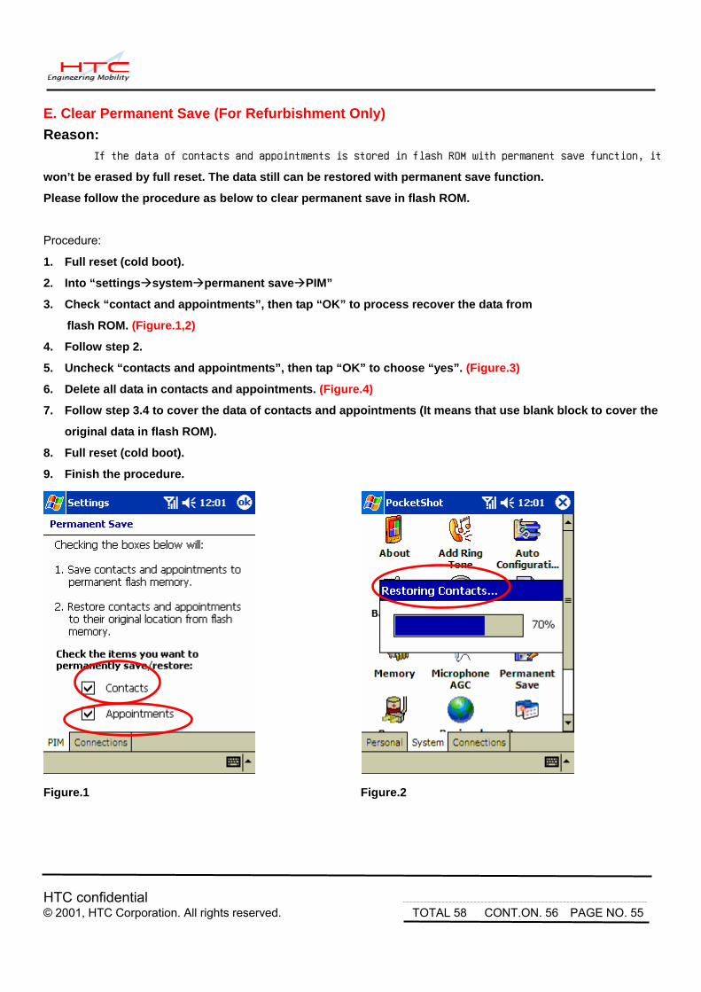
E. Clear Permanent Save (For Refurbishment Only) Reason:
If the data of contacts and appointments is stored in flash ROM with permanent save function, it
won’t be erased by full reset. The data still can be restored with permanent save function.
Please follow the procedure as below to clear permanent save in flash ROM.
Procedure:
1. Full reset (cold boot).
2. Into “settings system permanent save PIM”
3. Check “contact and appointments”, then tap “OK” to process recover the data from
flash ROM. (Figure.1,2)
4. Follow step 2.
5. Uncheck “contacts and appointments”, then tap “OK” to choose “yes”. (Figure.3)
6. Delete all data in contacts and appointments. (Figure.4)
7. Follow step 3.4 to cover the data of contacts and appointments (It means that use blank block to cover the
original data in flash ROM).
8. Full reset (cold boot).
9. Finish the procedure.
Figure.1 Figure.2

HTC confidential © 2001, HTC Corporation. All rights reserved. TOTAL 58 CONT.ON. 57 PAGE NO. 56
Figure.3 Figure.4

HTC confidential © 2001, HTC Corporation. All rights reserved. TOTAL 58 CONT.ON. 58 PAGE NO. 57
F. Battery rundown testing procedure Please refer following instruction to complete battery rundown test. 1. It is required to save power detect and model.txt in the same folder under WinCE 2. There is no necessary to adjust power management setting by using rundown test program (power
detect ver1.3). 3. Execute power detect under WinCE, then choose 1 hr option, unit will auto fall in Sleep mode 1 hr later. Please refer to the illustrated as below:
4.Find PowerCap.txt under the same path with power detect program to check the discharge status. The flow chart as below FYI.

HTC confidential © 2001, HTC Corporation. All rights reserved. TOTAL 58 CONT.ON. F PAGE NO. 58
5. Battery rundown test flow chart below:
Charge battery to full(at most 4 hrs, from 0%
to 100%)
Rundown test for 1 hour
Rundown testPowerCap.txt
Capacity>80%
GoodReplace battery or MB
Y
N


![[GUIDE_HOW-To] Beginner's _Getting Started_ Guide __ Root, Recovery, Roms Etc - Xda-Developers](https://img.pdfslide.net/doc/110x75/577ccf2c1a28ab9e788f1212/guidehow-to-beginners-getting-started-guide-root-recovery-roms.jpg)


![[TUT]MTK Android (Sp Flash Tool ) Tutorial - Xda-Developers](https://img.pdfslide.net/doc/110x75/552b69da550346a1478b466a/tutmtk-android-sp-flash-tool-tutorial-xda-developers.jpg)

![[GUIDE][30!10!2013]New to Adb and Fastboot Guide - Xda-Developers](https://img.pdfslide.net/doc/110x75/55cf96ba550346d0338d6566/guide30102013new-to-adb-and-fastboot-guide-xda-developers.jpg)
![[ROM] Hyperion 9 GM Final Build Final Rev + Update-01 - xda-developers](https://img.pdfslide.net/doc/110x75/55cf94af550346f57ba3b727/rom-hyperion-9-gm-final-build-final-rev-update-01-xda-developers.jpg)


![[Root]Moto g [Xt103x] [Easiest Method][All r… _ Moto g _ Xda Forum](https://img.pdfslide.net/doc/110x75/55cf9470550346f57ba207ab/rootmoto-g-xt103x-easiest-methodall-r-moto-g-xda-forum.jpg)


![[GUIDE][18th Dec][4Noobs] Flashing a FTF File Using Flashtool - Xda-Developers](https://img.pdfslide.net/doc/110x75/55cf98d8550346d0339a022f/guide18th-dec4noobs-flashing-a-ftf-file-using-flashtool-xda-developers.jpg)


![[GUIDE] Link2SD for Dummies _ Samsung Galaxy Young - Xda-Developers](https://img.pdfslide.net/doc/110x75/55cf981e550346d03395b3ef/guide-link2sd-for-dummies-samsung-galaxy-young-xda-developers.jpg)