Embed Size (px)
Citation preview
SERVICE MANUAL INFORMATION
SB-19-012 EXHAUST VALVE INSPECTION WORKSHOP MANUAL CORRECTION
GROUP: SERVICE MANUAL UPDATEBULLETIN NO: SB-19-012DATE: 4-10-2019
SUBJECT VEHICLES: 16MY-20MY Conventional Trucks equipped with an J08E.
The following is to inform you of the above caption. This service data should be attached to the relevant pages of the workshop manuals for maintenance and to use for servicing.
OVERVIEW: Change of exhaust valve inspection method.Workshop manual correction of Diagnostic Trouble Code DTC P0027, P0421, P2458 and P24A2.
ENGINE CONTROL SYSTEM (J08E)4–90
DTC: P0027EN01H16F01030F03001021
P0027: Exhaust Brake PerformanceINFORMATION
1. Technical description
<Description of malfunction>
• The engine ECU detected sticking of the exhaust brake valve.
2. DTC set condition(1) DTC detection condition
• DPR regeneration is in process.• The vehicle speed is 0 km/h {0 mph}.• The time of 60 seconds has elapsed after the exhaust brake was actuated.
(2) Judgment criteria• The difference between the fuel injection quantity while the exhaust brake is working and the fuel injection
quantity when the exhaust brake is not actuated is 5 mm3/st or less. And also, the difference between the airflow while the exhaust brake is working and the air flow when the exhaust brake is not actuated is -50 mg/cylor more.
3. Reset condition
• Immediately after normal status is resumed
4. Indication, warning or system control regulation when the DTC is set.
• MIL: ON• SVS light: OFF
5. Symptoms on the vehicle when the DTC is set
<Symptoms on the vehicle due to backup control (fail safe function)>
• –
<Symptoms on the vehicle due to malfunction>
• The exhaust brake does not work.• DPR regeneration is not terminated successfully.
6. Pre-inspection work
• Check that the battery voltage is in the normal range.
7. After-inspection work
• Clear all past DTCs.• Check that no DTC is detected after test drive.
8. Estimated failure factors
• Abnormality in characteristics of air flow sensor• Diesel throttle sticking• Bend, clogging, and crack of piping and hose• Improper adjustment of exhaust brake valve• Malfunction of exhaust brake valve
ENGINE CONTROL SYSTEM (J08E) 4–91
INSPECTION PROCEDURE: P0027
1. Set the starter switch to the "LOCK" position.
2. Connect the vehicle to HINO DX .
3. Set the starter switch to the "ON" position.
4. Select [Engine], and check if any DTC listed below other thanP0027 has been detected.P0101, P04D5, P2101
NOYES
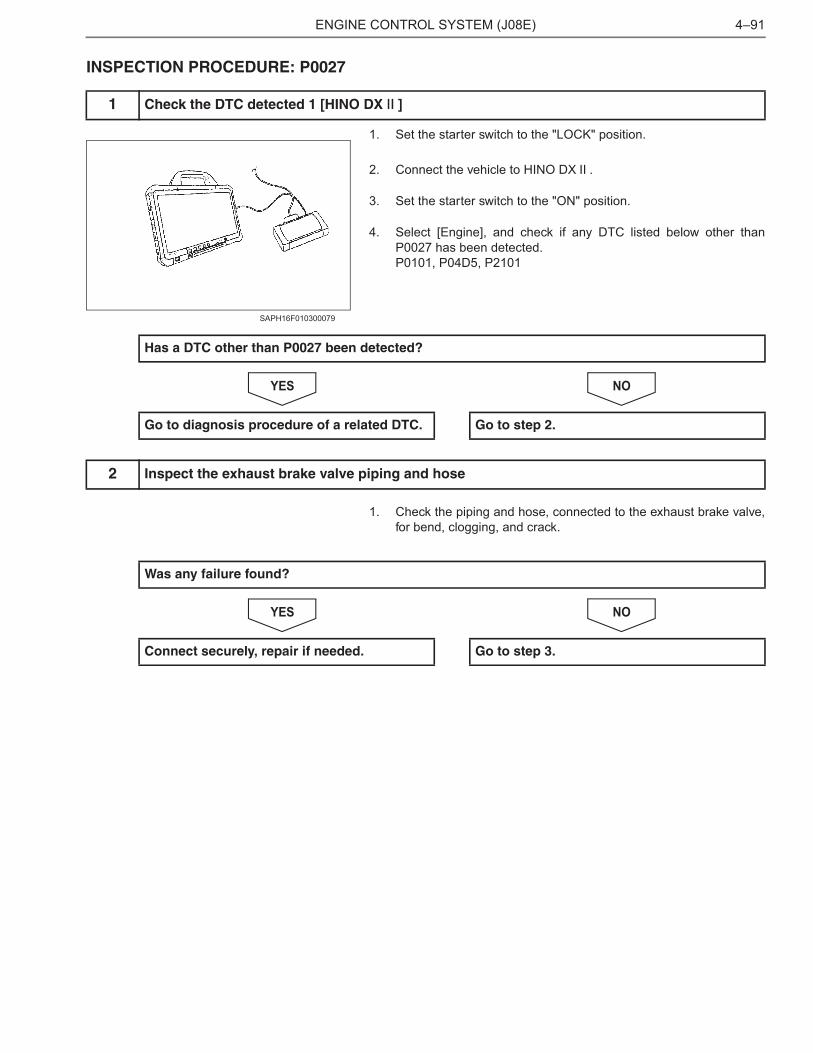
1. Check the piping and hose, connected to the exhaust brake valve,for bend, clogging, and crack.
NOYES
1 Check the DTC detected 1 [HINO DX ]
SAPH16F010300079
Has a DTC other than P0027 been detected?
Go to diagnosis procedure of a related DTC. Go to step 2.
2 Inspect the exhaust brake valve piping and hose
Was any failure found?
Connect securely, repair if needed. Go to step 3.
ENGINE CONTROL SYSTEM (J08E)4–92
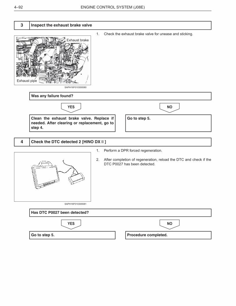
1. Check the exhaust brake valve for unease and sticking.
NOYES
1. Perform a DPR forced regeneration.
2. After completion of regeneration, reload the DTC and check if theDTC P0027 has been detected.
NOYES
3 Inspect the exhaust brake valve
Exhaust brakeExhaust brake
Exhaust pipe
SAPH16F010300080
Was any failure found?
Clean the exhaust brake valve. Replace ifneeded. After clearing or replacement, go tostep 4.
Go to step 5.
4 Check the DTC detected 2 [HINO DX ]
SAPH16F010300081
Has DTC P0027 been detected?
Go to step 5. Procedure completed.
ENGINE CONTROL SYSTEM (J08E) 4–93
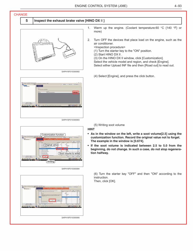
1. Warm up the engine. (Coolant temperature:60 �C {140 �F} ormore)
2. Turn OFF the devices that place load on the engine, such as theair conditioner.<Inspection procedure>(1) Turn the starter key to the "ON" position.(2) Start HINO DX .(3) On the HINO DX window, click [Customization].Select the vehicle model and region, and check [Engine].Select either Upload INF file and then [Road out] to read out.
(4) Select [Engine], and press the click button.
(5) Writing soot volumeHINT
• As in the window on the left, write a soot volume[2.5] using thecustomization function. Record the original value not to forget.The example in the window is [0.674].
• If the soot volume is indicated between 2.5 to 5.0 from thebeginning, do not change. In such a case, do not stop regenera-tion halfway.
(6) Turn the starter key "OFF" and then "ON" according to theinstruction.Then, click [OK].
5 Inspect the exhaust brake valve [HINO DX ]
SAPH16F010300082
SAPH16F010300083
Soot volume to write
Original value
Customization function
Writing
SAPH16F010300084
SAPH16F010300085
CHANGE
ENGINE CONTROL SYSTEM (J08E)4–94
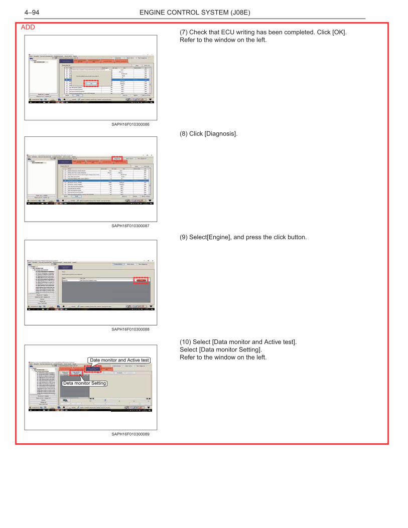
(7) Check that ECU writing has been completed. Click [OK].Refer to the window on the left.
(8) Click [Diagnosis].
(9) Select[Engine], and press the click button.
(10) Select [Data monitor and Active test].Select [Data monitor Setting].Refer to the window on the left.
SAPH16F010300086
SAPH16F010300087
SAPH16F010300088
Date monitor and Active test
Deta monitor Setting
SAPH16F010300089
ADD
ENGINE CONTROL SYSTEM (J08E) 4–95
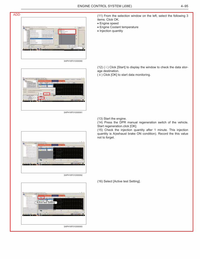
(11) From the selection window on the left, select the following 3items. Click OK.� Engine speed� Engine Coolant temperature� Injection quantity
(12) ( i ) Click [Start] to display the window to check the data stor-age destination.( ii ) Click [OK] to start data monitoring.
(13) Start the engine.(14) Press the DPR manual regeneration switch of the vehicle.Start regeneration.click [OK].(15) Check the injection quantity after 1 minute. This injectionquantity is A(exhaust brake ON condition). Record the this valuenot to forget.
(16) Select [Active test Setting].
SAPH16F010300090
( i )( ii )
SAPH16F010300091
SAPH16F010300092
Active test Setting
SAPH16F010300093
ADD
ENGINE CONTROL SYSTEM (J08E)4–96
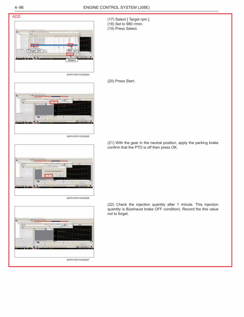
(17) Select [ Target rpm ].(18) Set to 980 r/min.(19) Press Select.
(20) Press Start.
(21) With the gear in the neutral position, apply the parking brakeconfirm that the PTO is off then press OK.
(22) Check the injection quantity after 1 minute. This injectionquantity is B(exhaust brake OFF condition). Record the this valuenot to forget.
Target rpm 980 rpm
Select
SAPH16F010300094
SAPH16F010300095
SAPH16F010300096
SAPH16F010300097
ADD
ENGINE CONTROL SYSTEM (J08E) 4–97
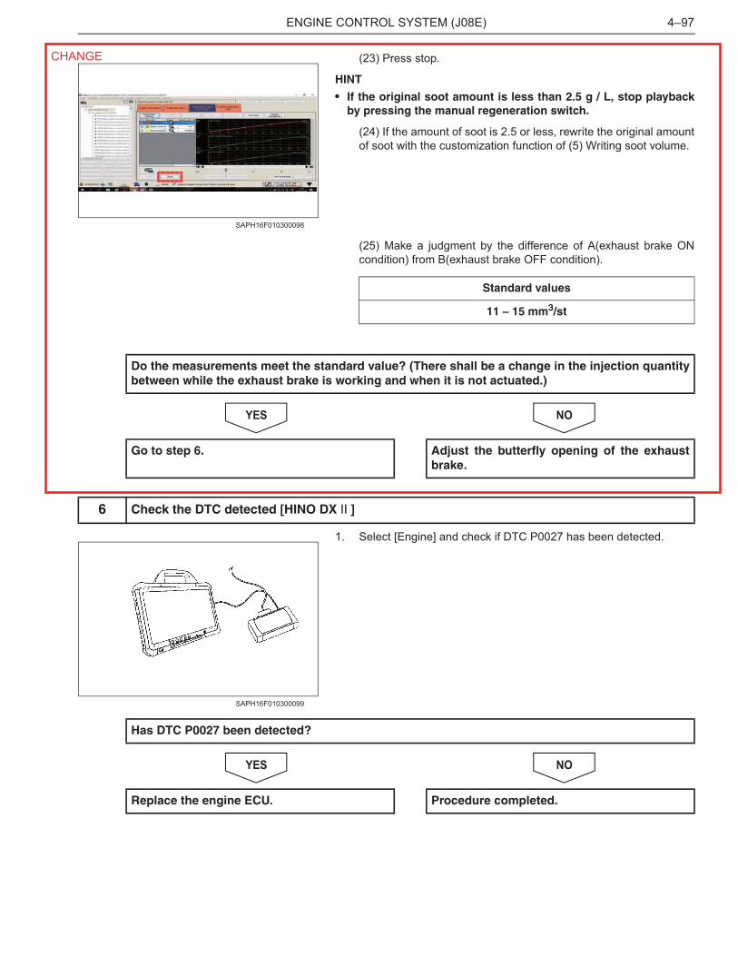
(23) Press stop.
HINT
• If the original soot amount is less than 2.5 g / L, stop playbackby pressing the manual regeneration switch.
(24) If the amount of soot is 2.5 or less, rewrite the original amountof soot with the customization function of (5) Writing soot volume.
(25) Make a judgment by the difference of A(exhaust brake ONcondition) from B(exhaust brake OFF condition).
NOYES
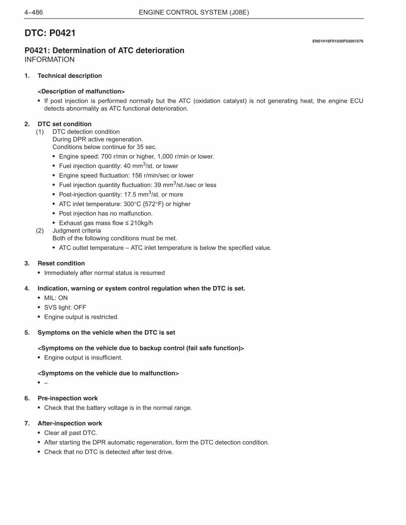
1. Select [Engine] and check if DTC P0027 has been detected.
NOYES
SAPH16F010300098
Standard values
11 – 15 mm3/st
Do the measurements meet the standard value? (There shall be a change in the injection quantitybetween while the exhaust brake is working and when it is not actuated.)
Go to step 6. Adjust the butterfly opening of the exhaustbrake.
6 Check the DTC detected [HINO DX ]
SAPH16F010300099
Has DTC P0027 been detected?
Replace the engine ECU. Procedure completed.
CHANGE
ENGINE CONTROL SYSTEM (J08E)4–486
DTC: P0421EN01H16F01030F03001076
P0421: Determination of ATC deteriorationINFORMATION
1. Technical description
<Description of malfunction>
• If post injection is performed normally but the ATC (oxidation catalyst) is not generating heat, the engine ECUdetects abnormality as ATC functional deterioration.
2. DTC set condition(1) DTC detection condition
During DPR active regeneration.Conditions below continue for 35 sec.• Engine speed: 700 r/min or higher, 1,000 r/min or lower.• Fuel injection quantity: 40 mm3/st. or lower• Engine speed fluctuation: 156 r/min/sec or lower• Fuel injection quantity fluctuation: 39 mm3/st./sec or less• Post-injection quantity: 17.5 mm3/st. or more• ATC inlet temperature: 300�C {572�F} or higher• Post injection has no malfunction.• Exhaust gas mass flow � 210kg/h
(2) Judgment criteriaBoth of the following conditions must be met.• ATC outlet temperature – ATC inlet temperature is below the specified value.
3. Reset condition
• Immediately after normal status is resumed
4. Indication, warning or system control regulation when the DTC is set.
• MIL: ON• SVS light: OFF• Engine output is restricted.
5. Symptoms on the vehicle when the DTC is set
<Symptoms on the vehicle due to backup control (fail safe function)>
• Engine output is insufficient.
<Symptoms on the vehicle due to malfunction>
• –
6. Pre-inspection work
• Check that the battery voltage is in the normal range.
7. After-inspection work
• Clear all past DTC.• After starting the DPR automatic regeneration, form the DTC detection condition.• Check that no DTC is detected after test drive.
ENGINE CONTROL SYSTEM (J08E) 4–487
8. Estimated failure factors
• ATC deterioration caused by use of low-grade fuel• Improper adjustment of exhaust brake valve.• Leak of exhaust gas from the pipe.• ATC inlet exhaust gas temperature sensor malfunction.• ATC outlet exhaust gas temperature sensor malfunction.
ENGINE CONTROL SYSTEM (J08E)4–488
INSPECTION PROCEDURE: P0421
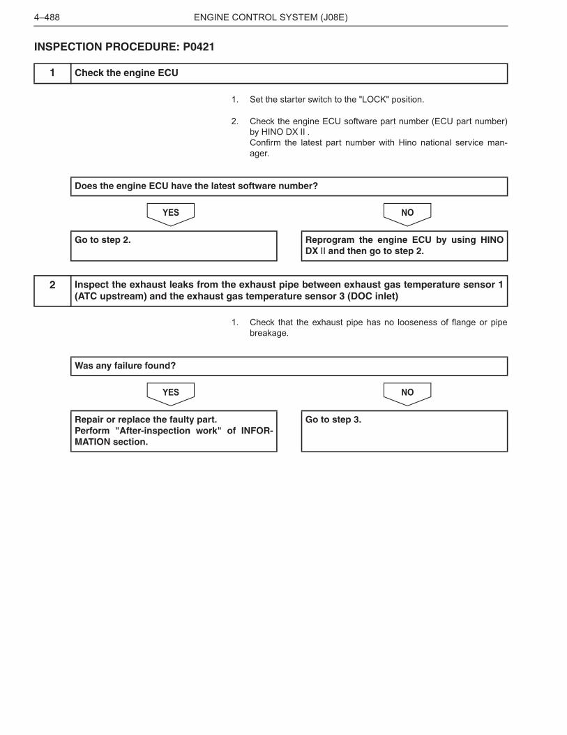
1. Set the starter switch to the "LOCK" position.
2. Check the engine ECU software part number (ECU part number)by HINO DX .Confirm the latest part number with Hino national service man-ager.
NOYES
1. Check that the exhaust pipe has no looseness of flange or pipebreakage.
NOYES
1 Check the engine ECU
Does the engine ECU have the latest software number?
Go to step 2. Reprogram the engine ECU by using HINODX and then go to step 2.
2 Inspect the exhaust leaks from the exhaust pipe between exhaust gas temperature sensor 1(ATC upstream) and the exhaust gas temperature sensor 3 (DOC inlet)
Was any failure found?
Repair or replace the faulty part.Perform "After-inspection work" of INFOR-MATION section.
Go to step 3.
ENGINE CONTROL SYSTEM (J08E) 4–489
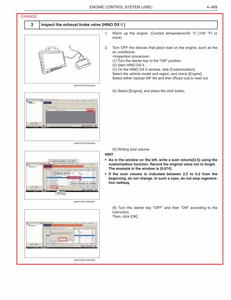
1. Warm up the engine. (Coolant temperature:60 �C {140 �F} ormore)
2. Turn OFF the devices that place load on the engine, such as theair conditioner.<Inspection procedure>(1) Turn the starter key to the "ON" position.(2) Start HINO DX .(3) On the HINO DX window, click [Customization].Select the vehicle model and region, and check [Engine].Select either Upload INF file and then [Road out] to read out.
(4) Select [Engine], and press the click button.
(5) Writing soot volumeHINT
• As in the window on the left, write a soot volume[2.5] using thecustomization function. Record the original value not to forget.The example in the window is [0.674].
• If the soot volume is indicated between 2.5 to 5.0 from thebeginning, do not change. In such a case, do not stop regenera-tion halfway.
(6) Turn the starter key "OFF" and then "ON" according to theinstruction.Then, click [OK].
3 Inspect the exhaust brake valve [HINO DX ]
SAPH16F010300489
SAPH16F010300490
Soot volume to write
Original value
Customization function
Writing
SAPH16F010300491
SAPH16F010300492
CHANGE
ENGINE CONTROL SYSTEM (J08E)4–490
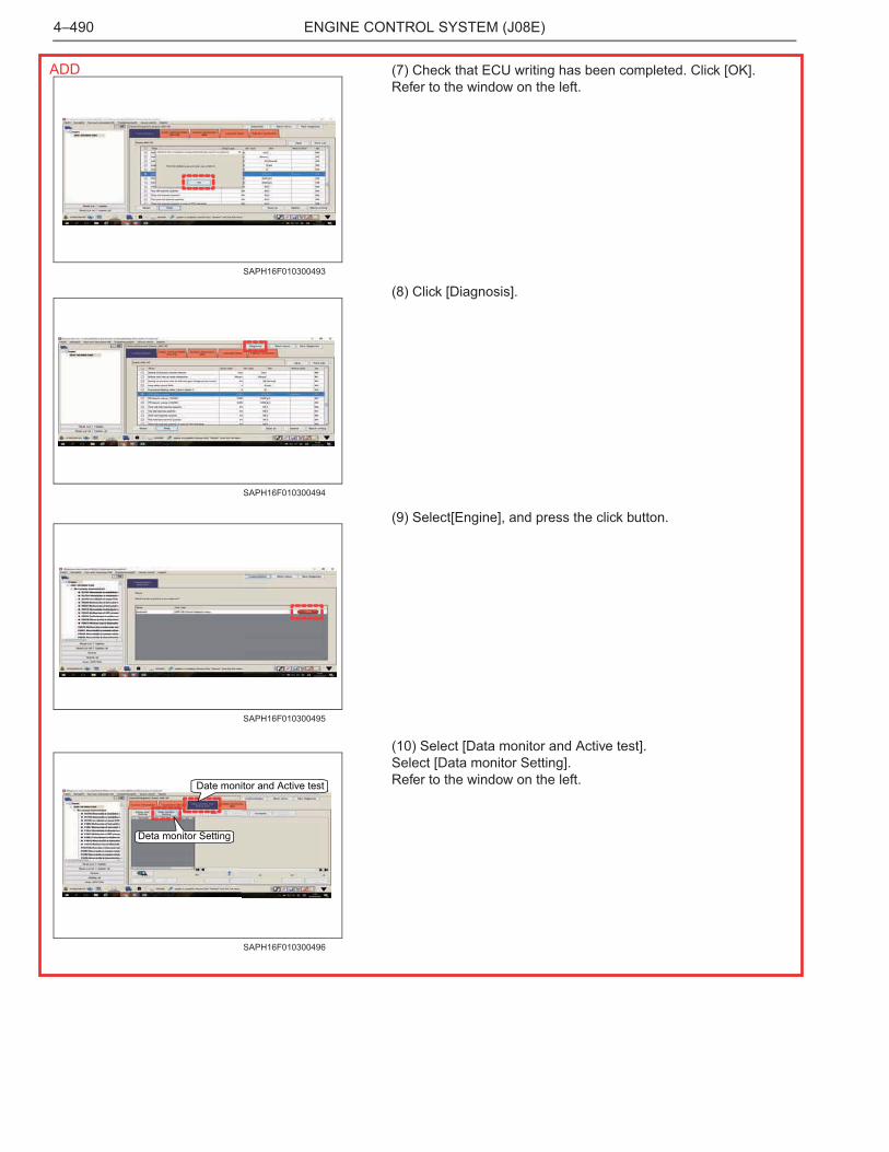
(7) Check that ECU writing has been completed. Click [OK].Refer to the window on the left.
(8) Click [Diagnosis].
(9) Select[Engine], and press the click button.
(10) Select [Data monitor and Active test].Select [Data monitor Setting].Refer to the window on the left.
SAPH16F010300493
SAPH16F010300494
SAPH16F010300495
Date monitor and Active test
Deta monitor Setting
SAPH16F010300496
ADD
ENGINE CONTROL SYSTEM (J08E) 4–491
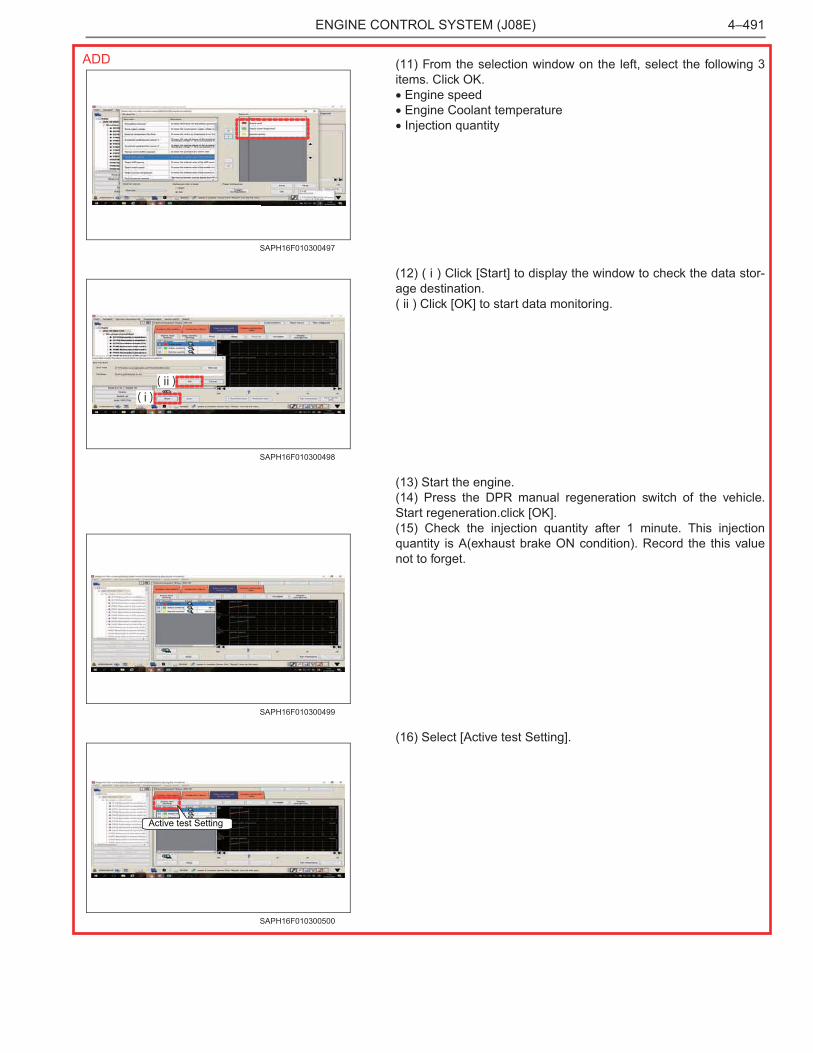
(11) From the selection window on the left, select the following 3items. Click OK.� Engine speed� Engine Coolant temperature� Injection quantity
(12) ( i ) Click [Start] to display the window to check the data stor-age destination.( ii ) Click [OK] to start data monitoring.
(13) Start the engine.(14) Press the DPR manual regeneration switch of the vehicle.Start regeneration.click [OK].(15) Check the injection quantity after 1 minute. This injectionquantity is A(exhaust brake ON condition). Record the this valuenot to forget.
(16) Select [Active test Setting].
SAPH16F010300497
( i )( ii )
SAPH16F010300498
SAPH16F010300499
Active test Setting
SAPH16F010300500
ADD
ENGINE CONTROL SYSTEM (J08E)4–492
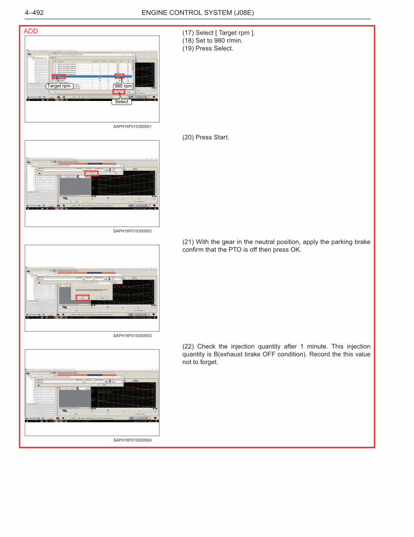
(17) Select [ Target rpm ].(18) Set to 980 r/min.(19) Press Select.
(20) Press Start.
(21) With the gear in the neutral position, apply the parking brakeconfirm that the PTO is off then press OK.
(22) Check the injection quantity after 1 minute. This injectionquantity is B(exhaust brake OFF condition). Record the this valuenot to forget.
Target rpm 980 rpm
Select
SAPH16F010300501
SAPH16F010300502
SAPH16F010300503
SAPH16F010300504
ADD
ENGINE CONTROL SYSTEM (J08E) 4–493
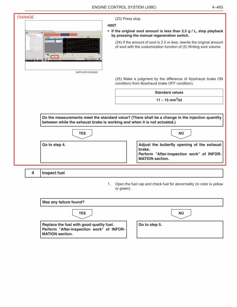
(23) Press stop.
HINT
• If the original soot amount is less than 2.5 g / L, stop playbackby pressing the manual regeneration switch.
(24) If the amount of soot is 2.5 or less, rewrite the original amountof soot with the customization function of (5) Writing soot volume.
(25) Make a judgment by the difference of A(exhaust brake ONcondition) from B(exhaust brake OFF condition).
NOYES
1. Open the fuel cap and check fuel for abnormality (in color is yellowor green).
NOYES
SAPH16F010300505
Standard values
11 – 15 mm3/st
Do the measurements meet the standard value? (There shall be a change in the injection quantitybetween while the exhaust brake is working and when it is not actuated.)
Go to step 4. Adjust the butterfly opening of the exhaustbrake.Perform "After-inspection work" of INFOR-MATION section.
4 Inspect fuel
Was any failure found?
Replace the fuel with good quality fuel.Perform "After-inspection work" of INFOR-MATION section.
Go to step 5.
CHANGE
ENGINE CONTROL SYSTEM (J08E)4–494
1. Check the connection of the exhaust gas temperature sensor 1(ATC upstream) and the exhaust gas temperature sensor 2 (ATCdownstream) connector (looseness and poor contact).
NOYES
1. Check the installation of the exhaust gas temperature sensor 1(ATC upstream) and the exhaust gas temperature sensor 2 (ATCdownstream).
2. Make sure there is no dirt, damage or clogging in the sensing unitof the exhaust gas temperature sensor 1 (ATC upstream) and theexhaust gas temperature sensor 2 (ATC downstream).
NOYES
5 Inspect the exhaust gas temperature sensor 1 (ATC upstream) and the exhaust gas tempera-ture sensor 2 (ATC downstream) connector
Was any failure found?
Connect securely, repair if needed.Go to step 6.
Go to step 6.
6 Inspect the exhaust gas temperature sensor 1 (ATC upstream) and the exhaust gas tempera-ture sensor 2 (ATC downstream)
Was any failure found?
Clean the sensing unit and install it properly.If damaged, replace the exhaust gas temper-ature sensor 1 (ATC upstream) and theexhaust gas temperature sensor 2 (ATCdownstream).Go to step 7.
Go to step 7.
ENGINE CONTROL SYSTEM (J08E) 4–495
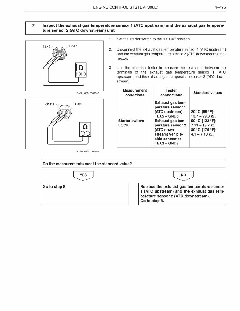
1. Set the starter switch to the "LOCK" position.
2. Disconnect the exhaust gas temperature sensor 1 (ATC upstream)and the exhaust gas temperature sensor 2 (ATC downstream) con-nector.
3. Use the electrical tester to measure the resistance between theterminals of the exhaust gas temperature sensor 1 (ATCupstream) and the exhaust gas temperature sensor 2 (ATC down-stream).
NOYES
7 Inspect the exhaust gas temperature sensor 1 (ATC upstream) and the exhaust gas tempera-ture sensor 2 (ATC downstream) unit
GND5TEX5
SAPH16F010300506
TEX3GND3
SAPH16F010300507
Measurementconditions
Testerconnections
Standard values
Starter switch: LOCK
Exhaust gas tem-perature sensor 1 (ATC upstream)TEX5 – GND5Exhaust gas tem-perature sensor 2 (ATC down-stream) vehicle-side connectorTEX3 – GND3
20 �C {68 �F}:13.7 – 29.8 k�50 �C {122 �F}:7.13 – 13.7 k�80 �C {176 �F}:4.1 – 7.13 k�
Do the measurements meet the standard value?
Go to step 8. Replace the exhaust gas temperature sensor1 (ATC upstream) and the exhaust gas tem-perature sensor 2 (ATC downstream).Go to step 8.
ENGINE CONTROL SYSTEM (J08E)4–496
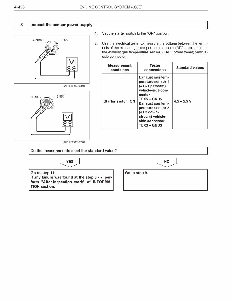
1. Set the starter switch to the "ON" position.
2. Use the electrical tester to measure the voltage between the termi-nals of the exhaust gas temperature sensor 1 (ATC upstream) andthe exhaust gas temperature sensor 2 (ATC downstream) vehicle-side connector.
NOYES
8 Inspect the sensor power supply
TEX5GND5
SAPH16F010300508
GND3TEX3
SAPH16F010300509
Measurementconditions
Testerconnections
Standard values
Starter switch: ON
Exhaust gas tem-perature sensor 1 (ATC upstream) vehicle-side con-nectorTEX5 – GND5Exhaust gas tem-perature sensor 2 (ATC down-stream) vehicle-side connectorTEX3 – GND3
4.5 – 5.5 V
Do the measurements meet the standard value?
Go to step 11.If any failure was found at the step 5 - 7, per-form "After-inspection work" of INFORMA-TION section.
Go to step 9.
ENGINE CONTROL SYSTEM (J08E) 4–497
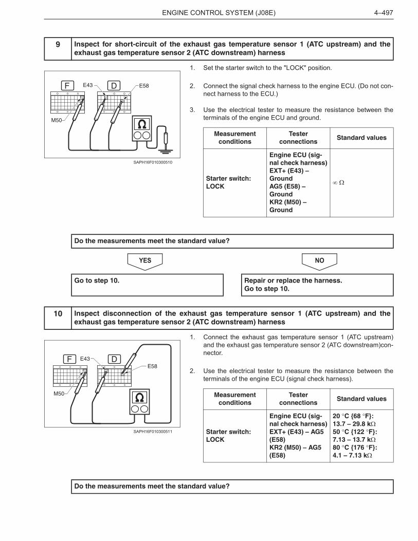
1. Set the starter switch to the "LOCK" position.
2. Connect the signal check harness to the engine ECU. (Do not con-nect harness to the ECU.)
3. Use the electrical tester to measure the resistance between theterminals of the engine ECU and ground.
NOYES
1. Connect the exhaust gas temperature sensor 1 (ATC upstream)and the exhaust gas temperature sensor 2 (ATC downstream)con-nector.
2. Use the electrical tester to measure the resistance between theterminals of the engine ECU (signal check harness).
9 Inspect for short-circuit of the exhaust gas temperature sensor 1 (ATC upstream) and theexhaust gas temperature sensor 2 (ATC downstream) harness
DF E43
M50
E58
SAPH16F010300510
Measurementconditions
Testerconnections
Standard values
Starter switch: LOCK
Engine ECU (sig-nal check harness)EXT+ (E43) – GroundAG5 (E58) – GroundKR2 (M50) – Ground
� �
Do the measurements meet the standard value?
Go to step 10. Repair or replace the harness.Go to step 10.
10 Inspect disconnection of the exhaust gas temperature sensor 1 (ATC upstream) and theexhaust gas temperature sensor 2 (ATC downstream) harness
DE43E58
F
M50
SAPH16F010300511
Measurementconditions
Testerconnections
Standard values
Starter switch: LOCK
Engine ECU (sig-nal check harness)EXT+ (E43) – AG5 (E58)KR2 (M50) – AG5 (E58)
20 �C {68 �F}:13.7 – 29.8 k�50 �C {122 �F}:7.13 – 13.7 k�80 �C {176 �F}:4.1 – 7.13 k�
Do the measurements meet the standard value?
ENGINE CONTROL SYSTEM (J08E)4–498
NOYES
1. Check the connection of the exhaust gas temperature sensor 3(DOC inlet) connector (looseness and poor contact).
NOYES
1. Check the installation of the exhaust gas temperature sensor 3(DOC inlet).
2. Make sure there is no dirt, damage or clogging in the sensing unitof the exhaust gas temperature sensor 3 (DOC inlet).
NOYES
Go to step 11.If any failure was found at the step 5 - 9, per-form "After-inspection work" of INFORMA-TION section.
Repair or replace the harness.Perform "After-inspection work" of INFOR-MATION section.
11 Inspect the exhaust gas temperature sensor 3 (DOC inlet) connector
Was any failure found?
Connect securely, repair if needed.Go to step 12.
Go to step 12.
12 Inspect the exhaust gas temperature sensor 3 (DOC inlet)
Was any failure found?
Clean the sensing unit and install it properly.If damaged, replace the exhaust gas temper-ature sensor 3 (DOC inlet).Go to step 13.
Go to step 13.
ENGINE CONTROL SYSTEM (J08E) 4–499
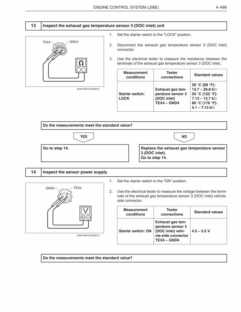
1. Set the starter switch to the "LOCK" position.
2. Disconnect the exhaust gas temperature sensor 3 (DOC inlet)connector.
3. Use the electrical tester to measure the resistance between theterminals of the exhaust gas temperature sensor 3 (DOC inlet).
NOYES
1. Set the starter switch to the "ON" position.
2. Use the electrical tester to measure the voltage between the termi-nals of the exhaust gas temperature sensor 3 (DOC inlet) vehicle-side connector.
13 Inspect the exhaust gas temperature sensor 3 (DOC inlet) unit
GND4TEX4
SAPH16F010300512
Measurementconditions
Testerconnections
Standard values
Starter switch: LOCK
Exhaust gas tem-perature sensor 3 (DOC inlet)TEX4 – GND4
20 �C {68 �F}:13.7 – 29.8 k�50 �C {122 �F}:7.13 – 13.7 k�80 �C {176 �F}:4.1 – 7.13 k�
Do the measurements meet the standard value?
Go to step 14. Replace the exhaust gas temperature sensor3 (DOC inlet).Go to step 14.
14 Inspect the sensor power supply
TEX4GND4
SAPH16F010300513
Measurementconditions
Testerconnections
Standard values
Starter switch: ON
Exhaust gas tem-perature sensor 3 (DOC inlet) vehi-cle-side connectorTEX4 – GND4
4.5 – 5.5 V
Do the measurements meet the standard value?
ENGINE CONTROL SYSTEM (J08E)4–500
NOYES
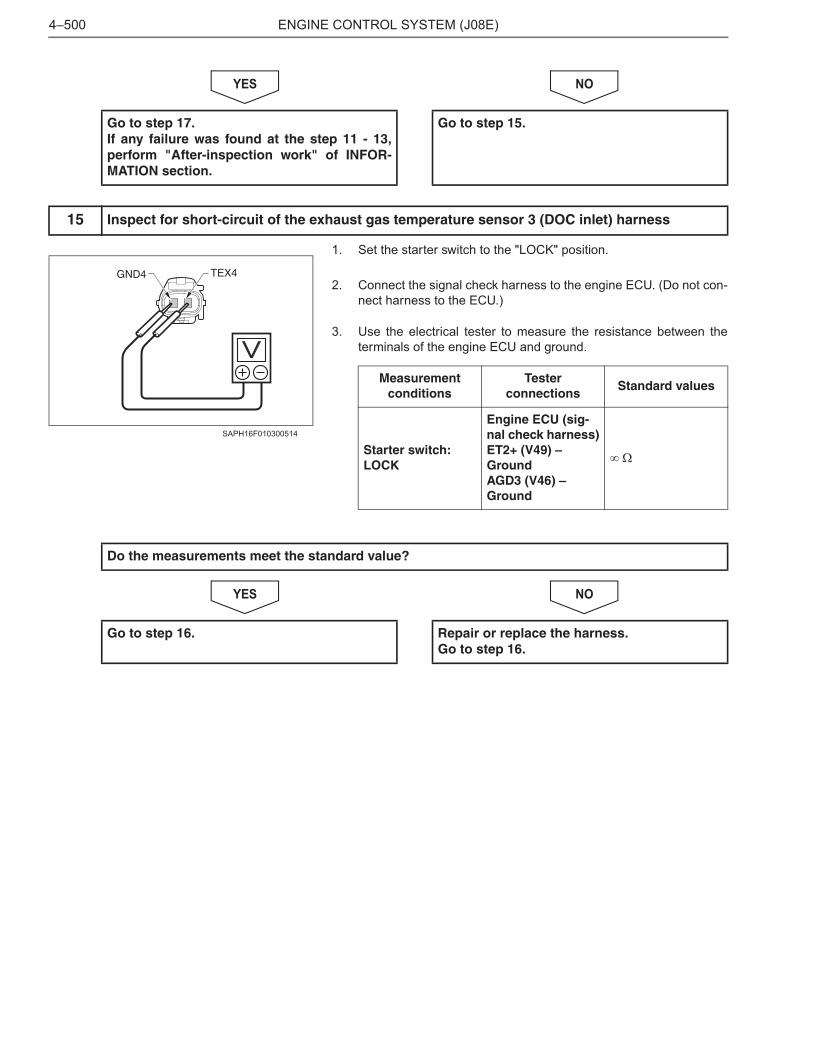
1. Set the starter switch to the "LOCK" position.
2. Connect the signal check harness to the engine ECU. (Do not con-nect harness to the ECU.)
3. Use the electrical tester to measure the resistance between theterminals of the engine ECU and ground.
NOYES
Go to step 17.If any failure was found at the step 11 - 13,perform "After-inspection work" of INFOR-MATION section.
Go to step 15.
15 Inspect for short-circuit of the exhaust gas temperature sensor 3 (DOC inlet) harness
TEX4GND4
SAPH16F010300514
Measurementconditions
Testerconnections
Standard values
Starter switch: LOCK
Engine ECU (sig-nal check harness)ET2+ (V49) – GroundAGD3 (V46) – Ground
� �
Do the measurements meet the standard value?
Go to step 16. Repair or replace the harness.Go to step 16.
ENGINE CONTROL SYSTEM (J08E) 4–501
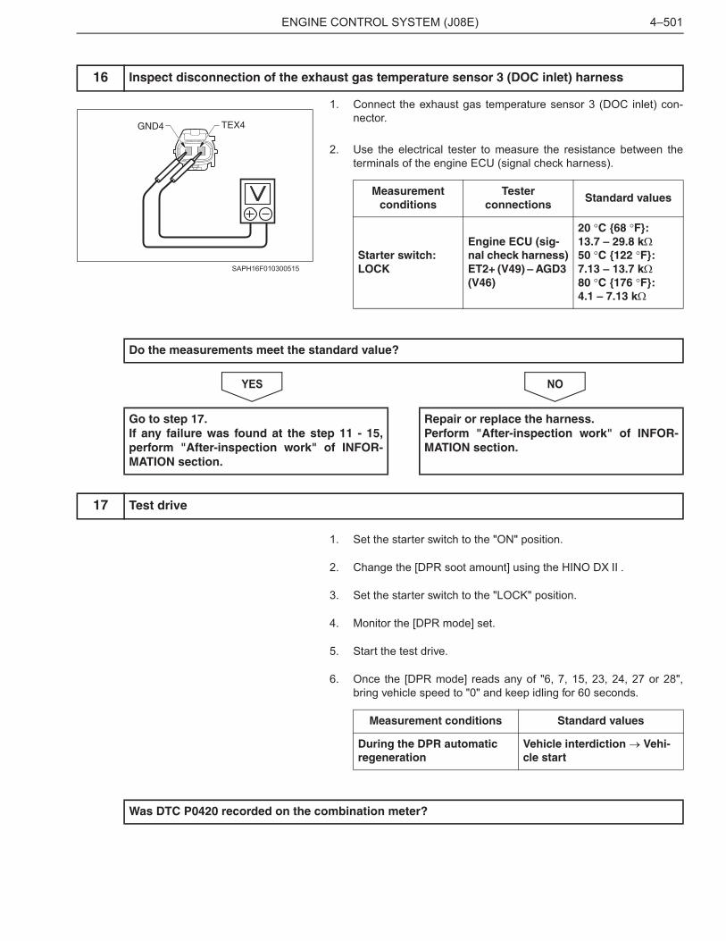
1. Connect the exhaust gas temperature sensor 3 (DOC inlet) con-nector.
2. Use the electrical tester to measure the resistance between theterminals of the engine ECU (signal check harness).
NOYES
1. Set the starter switch to the "ON" position.
2. Change the [DPR soot amount] using the HINO DX .
3. Set the starter switch to the "LOCK" position.
4. Monitor the [DPR mode] set.
5. Start the test drive.
6. Once the [DPR mode] reads any of "6, 7, 15, 23, 24, 27 or 28",bring vehicle speed to "0" and keep idling for 60 seconds.
16 Inspect disconnection of the exhaust gas temperature sensor 3 (DOC inlet) harness
TEX4GND4
SAPH16F010300515
Measurementconditions
Testerconnections
Standard values
Starter switch: LOCK
Engine ECU (sig-nal check harness)ET2+ (V49) – AGD3 (V46)
20 �C {68 �F}:13.7 – 29.8 k�50 �C {122 �F}:7.13 – 13.7 k�80 �C {176 �F}:4.1 – 7.13 k�
Do the measurements meet the standard value?
Go to step 17.If any failure was found at the step 11 - 15,perform "After-inspection work" of INFOR-MATION section.
Repair or replace the harness.Perform "After-inspection work" of INFOR-MATION section.
17 Test drive
Measurement conditions Standard values
During the DPR automatic regeneration
Vehicle interdiction � Vehi-cle start
Was DTC P0420 recorded on the combination meter?
ENGINE CONTROL SYSTEM (J08E)4–502
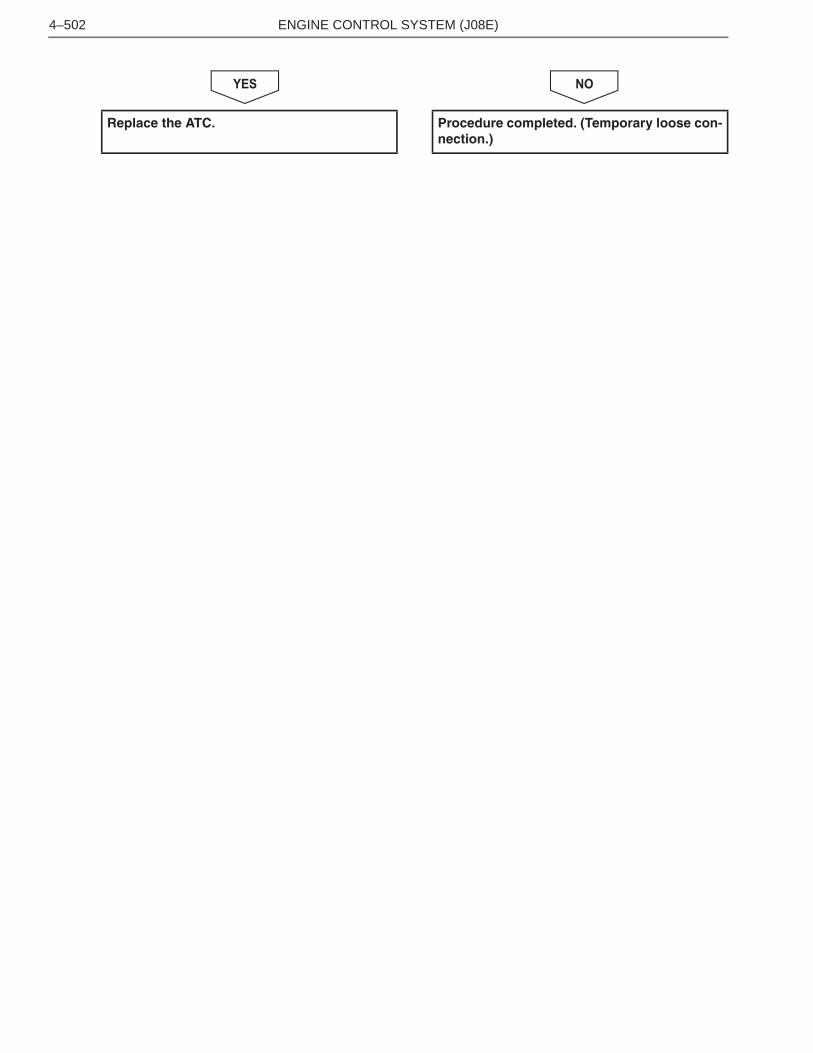
NOYES
Replace the ATC. Procedure completed. (Temporary loose con-nection.)
ENGINE CONTROL SYSTEM (J08E)4–1228
DTC: P2458EN01H16F01030F03001179
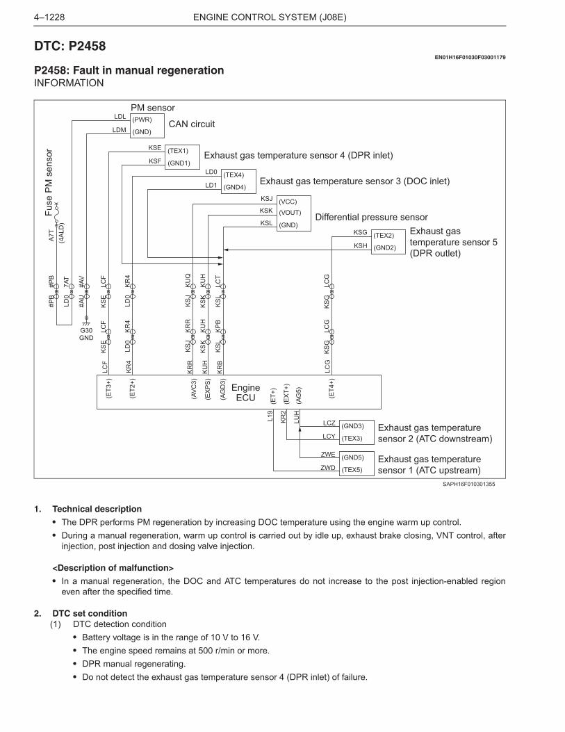
P2458: Fault in manual regenerationINFORMATION
1. Technical description
• The DPR performs PM regeneration by increasing DOC temperature using the engine warm up control.• During a manual regeneration, warm up control is carried out by idle up, exhaust brake closing, VNT control, after
injection, post injection and dosing valve injection.
<Description of malfunction>
• In a manual regeneration, the DOC and ATC temperatures do not increase to the post injection-enabled regioneven after the specified time.
2. DTC set condition(1) DTC detection condition
• Battery voltage is in the range of 10 V to 16 V.• The engine speed remains at 500 r/min or more.• DPR manual regenerating.• Do not detect the exhaust gas temperature sensor 4 (DPR inlet) of failure.
#AU
#AV
LD0
7AT
#PB
#PB
A7T
Fuse
PM
sen
sor
(4A
LD)
KS
ELC
F
LD0
KR
4
KS
JK
RR
KS
KK
UH
KS
LK
PB
KS
GLC
G
KS
ELC
F
LD0
KR
4
KS
JK
UQ
KS
KK
UH
KS
LLC
T
KS
GLC
G
(ET3
+)
(ET4
+)
(EX
PS
)
(AG
D3)
(AV
C3)
LCG
KU
H
KR
B
KR
R
(TEX1)
(GND1)KSF
KSE
LCF
(ET2
+)K
R4
Exhaust gas temperature sensor 4 (DPR inlet)
(TEX4)
(GND4)LD1
LD0Exhaust gas temperature sensor 3 (DOC inlet)
(TEX2)
(GND2)KSH
KSG Exhaust gastemperature sensor 5(DPR outlet)
(GND3)
(TEX3)LCY
LCZ
G30GND
(EX
T+)
(AG
5)LU
H
KR
2
Exhaust gas temperaturesensor 2 (ATC downstream)
(VCC)
(GND)KSL(VOUT)KSK
KSJ
Differential pressure sensor
EngineECU (E
T+)
L19
(GND5)
(TEX5)ZWD
ZWE Exhaust gas temperaturesensor 1 (ATC upstream)
(PWR)
(GND)LDM
LDLCAN circuit
PM sensor
SAPH16F010301355
ENGINE CONTROL SYSTEM (J08E) 4–1229
(2) Judgment criteria• After a manual DPR regeneration is started, the DOC temperature is still below 200 �C {392 �F} and the ATC
temperature is still below 230 �C {446 �F} even after 30 minutes.
3. Reset condition
• DPR memory is reset by the diagnostic tool (HINO DX ).
4. Indication, warning or system control regulation when the DTC is set.
• MIL: OFF• SVS light: ON• Engine output is restricted.
5. Symptoms on the vehicle when the DTC is set
<Symptoms on the vehicle due to backup control (fail safe function)>
• Engine output is insufficient.
<Symptoms on the vehicle due to malfunction>
• Do not DPR regeneration.
6. Pre-inspection work
• Check that the battery voltage is in the normal range.
7. After-inspection work
• Clear all past DTCs.• Check that no DTC is detected after test drive.
8. Estimated failure factors
• Soot clogging of the aftertreatment fuel injector housing.
Drop in injection quantity of fuel injection systemFailure of VNT systemExhaust gas temperature sensor 4 (DPR inlet):
• Loose/disconnected sensor of failure in sensing area (contamination, clogging or damaged)• Abnormal resistance of sensor• Failure in engine ECU sensor power supply
Exhaust gas temperature sensor 1 (ATC upstream)
• Loose/disconnected sensor of failure in sensing area (contamination, clogging or damaged)• Abnormal resistance of sensor• Failure in engine ECU sensor power supply
Exhaust brake
• Malfunction of exhaust brake• Improper adjustment of exhaust brake (The difference between the injection quantities in active and inactive condi-
tions is out of the standard)
Gas leaks in the middle of the exhaust systemFailure of coolant temperature sensor (low temperature stuck)
ENGINE CONTROL SYSTEM (J08E)4–1230
INSPECTION PROCEDURE: P2458
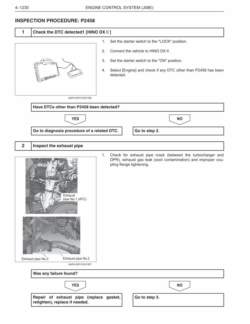
1. Set the starter switch to the "LOCK" position.
2. Connect the vehicle to HINO DX .
3. Set the starter switch to the "ON" position.
4. Select [Engine] and check if any DTC other than P2458 has beendetected.
NOYES
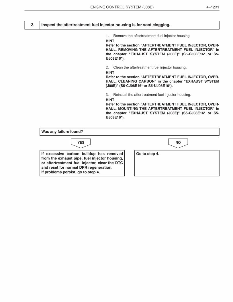
1. Check for exhaust pipe crack (between the turbocharger andDPR), exhaust gas leak (soot contamination) and improper cou-pling flange tightening.
NOYES
1 Check the DTC detected1 [HINO DX ]
SAPH16F010301356
Have DTCs other than P2458 been detected?
Go to diagnosis procedure of a related DTC. Go to step 2.
2 Inspect the exhaust pipe
Exhaust pipe No.2Exhaust pipe No.3
Exhaustpipe No.1 (ATC)
SAPH16F010301357
Was any failure found?
Repair of exhaust pipe (replace gasket,retighten), replace if needed.
Go to step 3.
ENGINE CONTROL SYSTEM (J08E) 4–1231
1. Remove the aftertreatment fuel injector housing.HINTRefer to the section "AFTERTREATMENT FUEL INJECTOR, OVER-HAUL, REMOVING THE AFTERTREATMENT FUEL INJECTOR" inthe chapter "EXHAUST SYSTEM (J08E)" (S5-CJ08E16* or S5-UJ08E16*).
2. Clean the aftertreatment fuel injector housing.HINTRefer to the section "AFTERTREATMENT FUEL INJECTOR, OVER-HAUL, CLEANING CARBON" in the chapter "EXHAUST SYSTEM(J08E)" (S5-CJ08E16* or S5-UJ08E16*).
3. Reinstall the aftertreatment fuel injector housing.HINTRefer to the section "AFTERTREATMENT FUEL INJECTOR, OVER-HAUL, MOUNTING THE AFTERTREATMENT FUEL INJECTOR" inthe chapter "EXHAUST SYSTEM (J08E)" (S5-CJ08E16* or S5-UJ08E16*).
NOYES
3 Inspect the aftertreatment fuel injector housing is for soot clogging.
Was any failure found?
If excessive carbon buildup has removedfrom the exhaust pipe, fuel injector housing,or aftertreatment fuel injector, clear the DTCand reset for normal DPR regeneration.If problems persist, go to step 4.
Go to step 4.
ENGINE CONTROL SYSTEM (J08E)4–1232
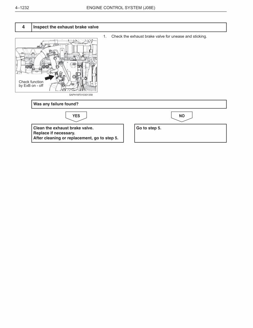
1. Check the exhaust brake valve for unease and sticking.
NOYES
4 Inspect the exhaust brake valve
Check function by ExB on - off
SAPH16F010301358
Was any failure found?
Clean the exhaust brake valve.Replace if necessary.After cleaning or replacement, go to step 5.
Go to step 5.

ENGINE CONTROL SYSTEM (J08E) 4–1233
1. Warm up the engine. (Coolant temperature:60 �C {140 �F} ormore)
2. Turn OFF the devices that place load on the engine, such as theair conditioner.<Inspection procedure>(1) Turn the starter key to the "ON" position.(2) Start HINO DX .(3) On the HINO DX window, click [Customization].Select the vehicle model and region, and check [Engine].Select either Upload INF file and then [Road out] to read out.
(4) Select [Engine], and press the click button.
(5) Writing soot volumeHINT
• As in the window on the left, write a soot volume[2.5] using thecustomization function. Record the original value not to forget.The example in the window is [0.674].
• If the soot volume is indicated between 2.5 to 5.0 from thebeginning, do not change. In such a case, do not stop regenera-tion halfway.
(6) Turn the starter key "OFF" and then "ON" according to theinstruction.Then, click [OK].
5 Inspect the exhaust brake valve [HINO DX ]
SAPH16F010301359
SAPH16F010301360
Soot volume to write
Original value
Customization function
Writing
SAPH16F010301361
SAPH16F010301362
CHANGE
ENGINE CONTROL SYSTEM (J08E)4–1234
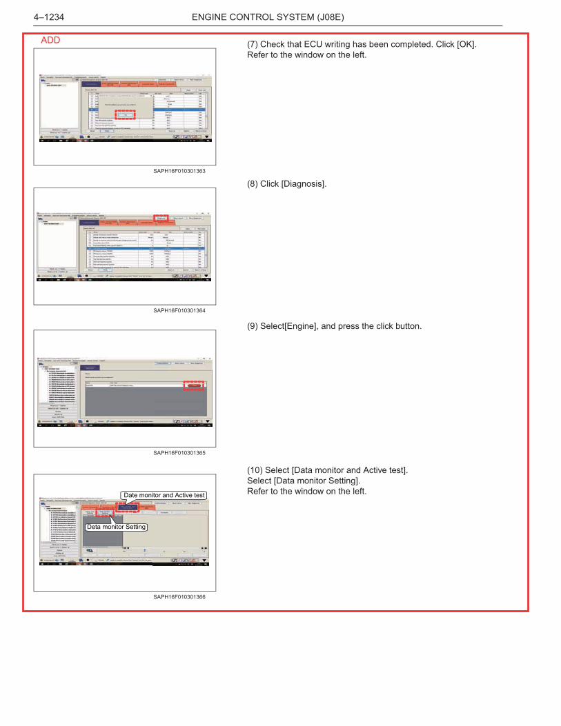
(7) Check that ECU writing has been completed. Click [OK].Refer to the window on the left.
(8) Click [Diagnosis].
(9) Select[Engine], and press the click button.
(10) Select [Data monitor and Active test].Select [Data monitor Setting].Refer to the window on the left.
SAPH16F010301363
SAPH16F010301364
SAPH16F010301365
Date monitor and Active test
Deta monitor Setting
SAPH16F010301366
ADD

ENGINE CONTROL SYSTEM (J08E) 4–1235
(11) From the selection window on the left, select the following 3items. Click OK.� Engine speed� Engine Coolant temperature� Injection quantity
(12) ( i ) Click [Start] to display the window to check the data stor-age destination.( ii ) Click [OK] to start data monitoring.
(13) Start the engine.(14) Press the DPR manual regeneration switch of the vehicle.Start regeneration.click [OK].(15) Check the injection quantity after 1 minute. This injectionquantity is A(exhaust brake ON condition). Record the this valuenot to forget.
(16) Select [Active test Setting].
SAPH16F010301367
( i )( ii )
SAPH16F010301368
SAPH16F010301369
Active test Setting
SAPH16F010301370
ADD
ENGINE CONTROL SYSTEM (J08E)4–1236
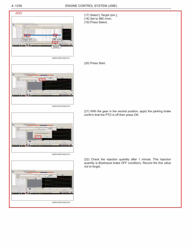
(17) Select [ Target rpm ].(18) Set to 980 r/min.(19) Press Select.
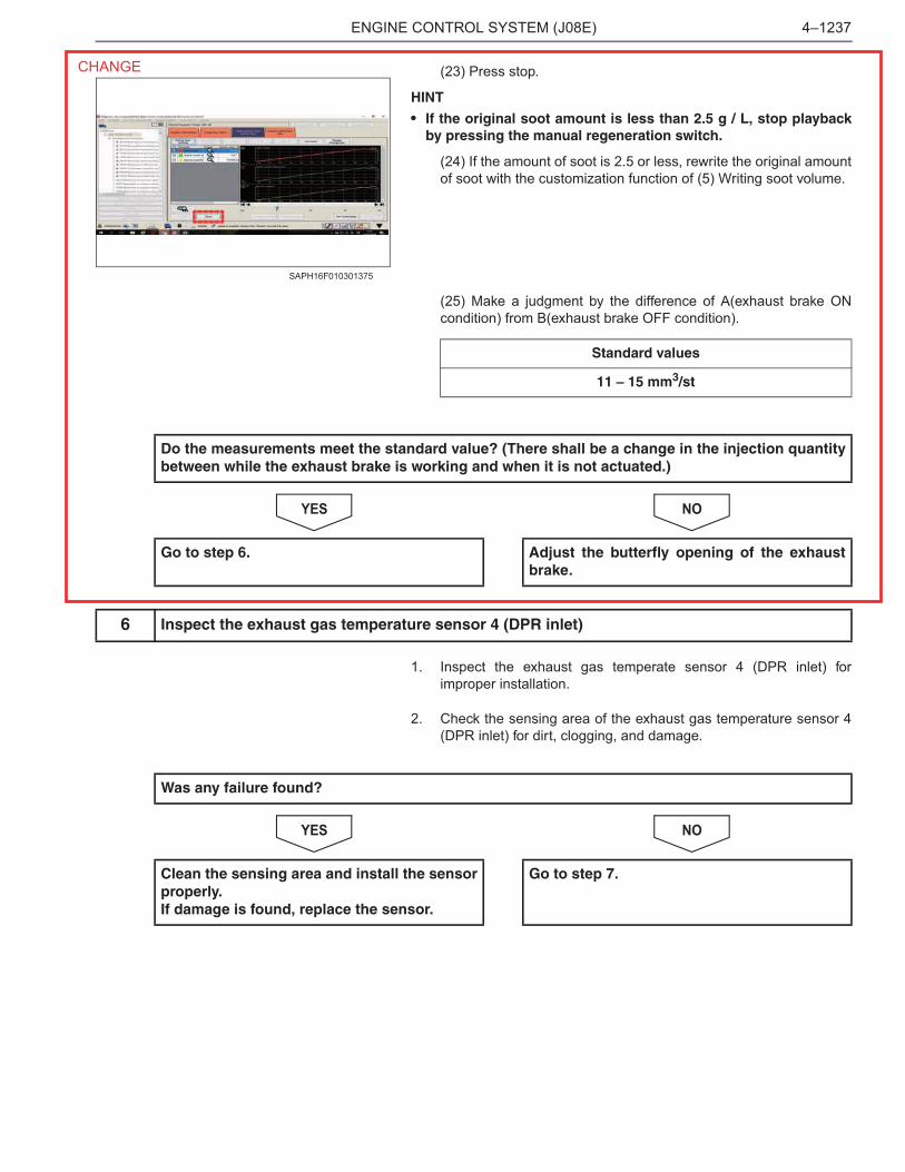
(20) Press Start.
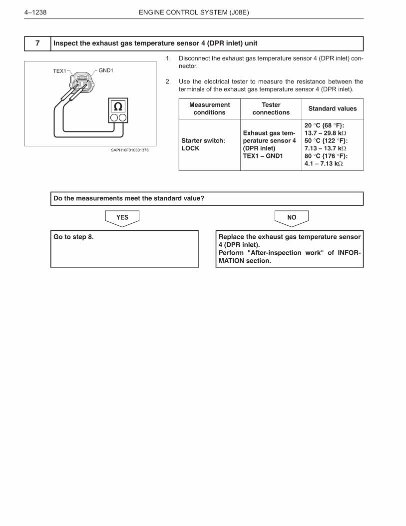
(21) With the gear in the neutral position, apply the parking brakeconfirm that the PTO is off then press OK.
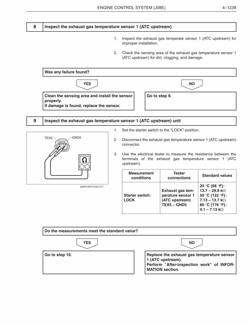
(22) Check the injection quantity after 1 minute. This injectionquantity is B(exhaust brake OFF condition). Record the this valuenot to forget.
Target rpm 980 rpm
Select
SAPH16F010301371
SAPH16F010301372
SAPH16F010301373
SAPH16F010301374
ADD
ENGINE CONTROL SYSTEM (J08E) 4–1237
(23) Press stop.
HINT
• If the original soot amount is less than 2.5 g / L, stop playbackby pressing the manual regeneration switch.
(24) If the amount of soot is 2.5 or less, rewrite the original amountof soot with the customization function of (5) Writing soot volume.
(25) Make a judgment by the difference of A(exhaust brake ONcondition) from B(exhaust brake OFF condition).
NOYES
1. Inspect the exhaust gas temperate sensor 4 (DPR inlet) forimproper installation.
2. Check the sensing area of the exhaust gas temperature sensor 4(DPR inlet) for dirt, clogging, and damage.
NOYES
SAPH16F010301375
Standard values
11 – 15 mm3/st
Do the measurements meet the standard value? (There shall be a change in the injection quantitybetween while the exhaust brake is working and when it is not actuated.)
Go to step 6. Adjust the butterfly opening of the exhaustbrake.
6 Inspect the exhaust gas temperature sensor 4 (DPR inlet)
Was any failure found?
Clean the sensing area and install the sensorproperly.If damage is found, replace the sensor.
Go to step 7.
CHANGE
ENGINE CONTROL SYSTEM (J08E)4–1238
1. Disconnect the exhaust gas temperature sensor 4 (DPR inlet) con-nector.
2. Use the electrical tester to measure the resistance between theterminals of the exhaust gas temperature sensor 4 (DPR inlet).
NOYES
7 Inspect the exhaust gas temperature sensor 4 (DPR inlet) unit
GND1TEX1
SAPH16F010301376
Measurementconditions
Tester connections
Standard values
Starter switch: LOCK
Exhaust gas tem-perature sensor 4 (DPR inlet)TEX1 – GND1
20 �C {68 �F}: 13.7 – 29.8 k�50 �C {122 �F}: 7.13 – 13.7 k�80 �C {176 �F}: 4.1 – 7.13 k�
Do the measurements meet the standard value?
Go to step 8. Replace the exhaust gas temperature sensor4 (DPR inlet).Perform "After-inspection work" of INFOR-MATION section.
ENGINE CONTROL SYSTEM (J08E) 4–1239
1. Inspect the exhaust gas temperate sensor 1 (ATC upstream) forimproper installation.
2. Check the sensing area of the exhaust gas temperature sensor 1(ATC upstream) for dirt, clogging, and damage.
NOYES
1. Set the starter switch to the "LOCK" position.
2. Disconnect the exhaust gas temperature sensor 1 (ATC upstream)connector.
3. Use the electrical tester to measure the resistance between theterminals of the exhaust gas temperature sensor 1 (ATCupstream).
NOYES
8 Inspect the exhaust gas temperature sensor 1 (ATC upstream)
Was any failure found?
Clean the sensing area and install the sensorproperly.If damage is found, replace the sensor.
Go to step 9.
9 Inspect the exhaust gas temperature sensor 1 (ATC upstream) unit
GND5TEX5
SAPH16F010301377
Measurementconditions
Tester connections
Standard values
Starter switch: LOCK
Exhaust gas tem-perature sensor 1 (ATC upstream)TEX5 – GND5
20 �C {68 �F}: 13.7 – 29.8 k�50 �C {122 �F}: 7.13 – 13.7 k�80 �C {176 �F}: 4.1 – 7.13 k�
Do the measurements meet the standard value?
Go to step 10. Replace the exhaust gas temperature sensor1 (ATC upstream).Perform "After-inspection work" of INFOR-MATION section.
ENGINE CONTROL SYSTEM (J08E)4–1240
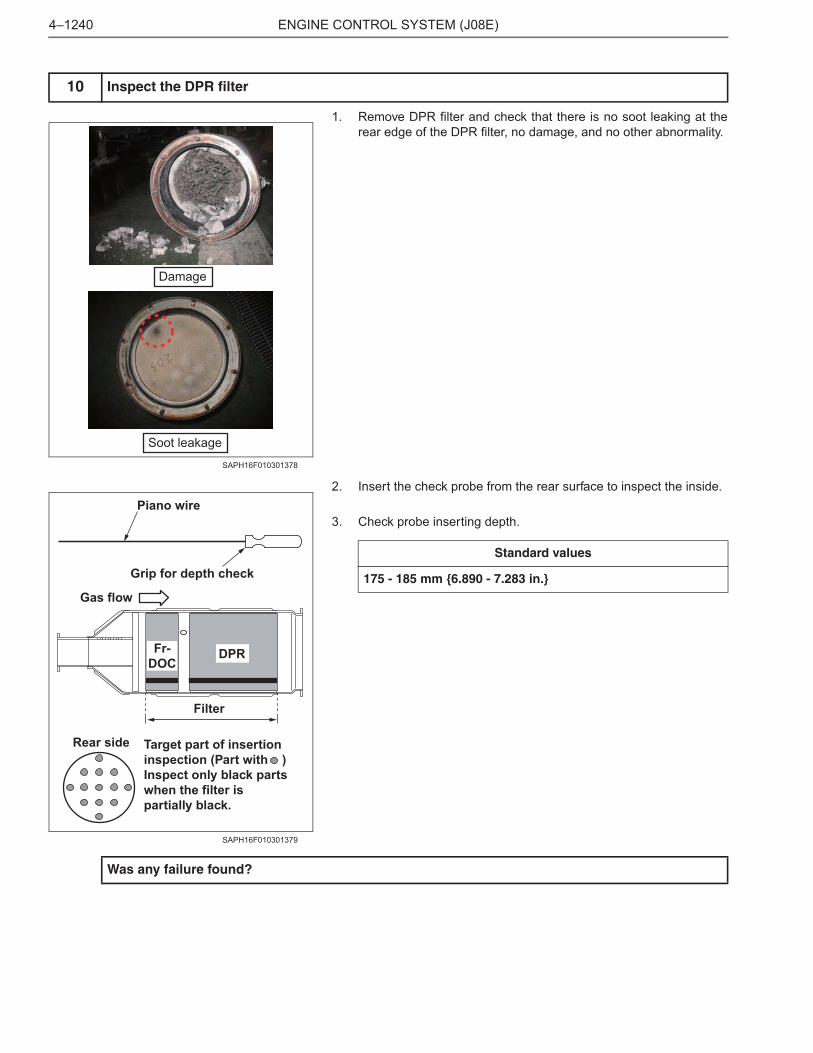
1. Remove DPR filter and check that there is no soot leaking at therear edge of the DPR filter, no damage, and no other abnormality.
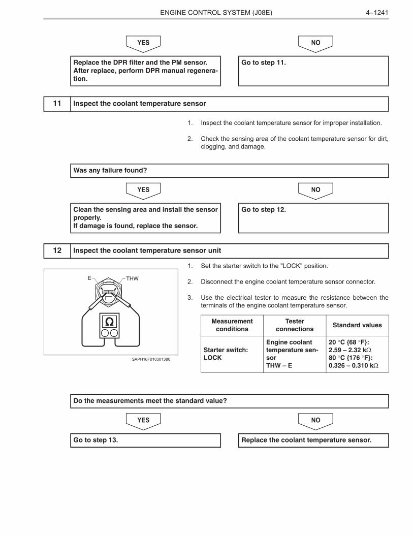
2. Insert the check probe from the rear surface to inspect the inside.
3. Check probe inserting depth.
10 Inspect the DPR filter
Damage
Soot leakage
SAPH16F010301378
Piano wire
Grip for depth check
Gas flow
DPR
Filter
Rear side Target part of insertion inspection (Part with )Inspect only black parts when the filter is partially black.
Fr-DOC
SAPH16F010301379
Standard values
175 - 185 mm {6.890 - 7.283 in.}
Was any failure found?
ENGINE CONTROL SYSTEM (J08E) 4–1241
NOYES
1. Inspect the coolant temperature sensor for improper installation.
2. Check the sensing area of the coolant temperature sensor for dirt,clogging, and damage.
NOYES
1. Set the starter switch to the "LOCK" position.
2. Disconnect the engine coolant temperature sensor connector.
3. Use the electrical tester to measure the resistance between theterminals of the engine coolant temperature sensor.
NOYES
Replace the DPR filter and the PM sensor.After replace, perform DPR manual regenera-tion.
Go to step 11.
11 Inspect the coolant temperature sensor
Was any failure found?
Clean the sensing area and install the sensorproperly.If damage is found, replace the sensor.
Go to step 12.
12 Inspect the coolant temperature sensor unit
E THW
SAPH16F010301380
Measurementconditions
Tester connections
Standard values
Starter switch: LOCK
Engine coolant temperature sen-sor THW – E
20 �C {68 �F}: 2.59 – 2.32 k�80 �C {176 �F}: 0.326 – 0.310 k�
Do the measurements meet the standard value?
Go to step 13. Replace the coolant temperature sensor.
ENGINE CONTROL SYSTEM (J08E)4–1242
1. Perform a basic engine check using the ENGINE BASIC INSPEC-TION SHEET. (Check the fuel injection amount, check the VNTactivate.)
NOYES
13 Perform a basic engine check
Was any failure found?
Repair or replace the faulty part.Perform "After-inspection work" of INFOR-MATION section.
Go to step 14.
ENGINE CONTROL SYSTEM (J08E) 4–1243
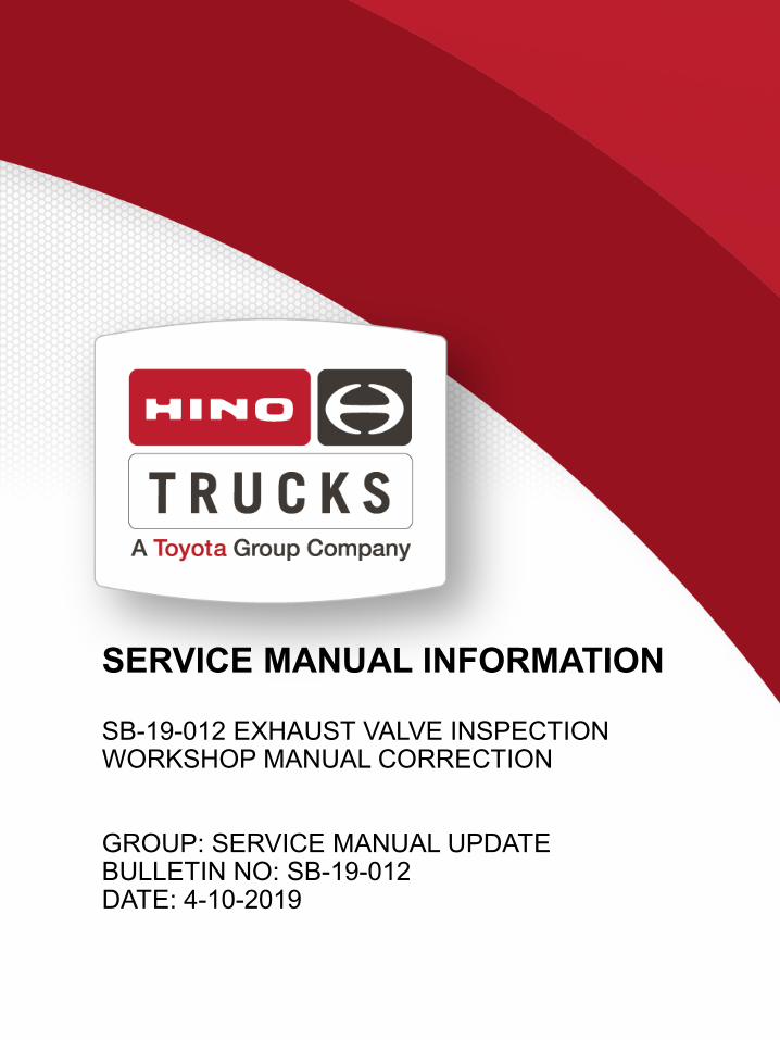
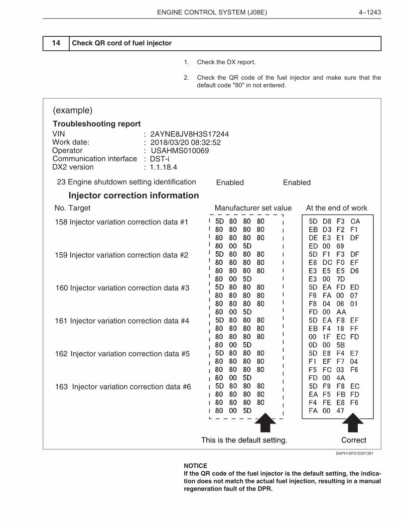
1. Check the DX report.
2. Check the QR code of the fuel injector and make sure that thedefault code "80" in not entered.
NOTICEIf the QR code of the fuel injector is the default setting, the indica-tion does not match the actual fuel injection, resulting in a manualregeneration fault of the DPR.
14 Check QR cord of fuel injector
Troubleshooting report (example)
VIN : 2AYNE8JV8H3S17244 Work date: : 2018/03/20 08:32:52 Operator : USAHMS010069 Communication interface : DST-i DX2 version : 1.1.18.4
23 Engine shutdown setting identification
Injector correction informationNo. Target
158 Injector variation correction data #1
159 Injector variation correction data #2
160 Injector variation correction data #3
161 Injector variation correction data #4
162 Injector variation correction data #5
163 Injector variation correction data #6
Manufacturer set value
Enabled Enabled
At the end of work
This is the default setting. Correct
SAPH16F010301381
ENGINE CONTROL SYSTEM (J08E)4–1244
NOYES
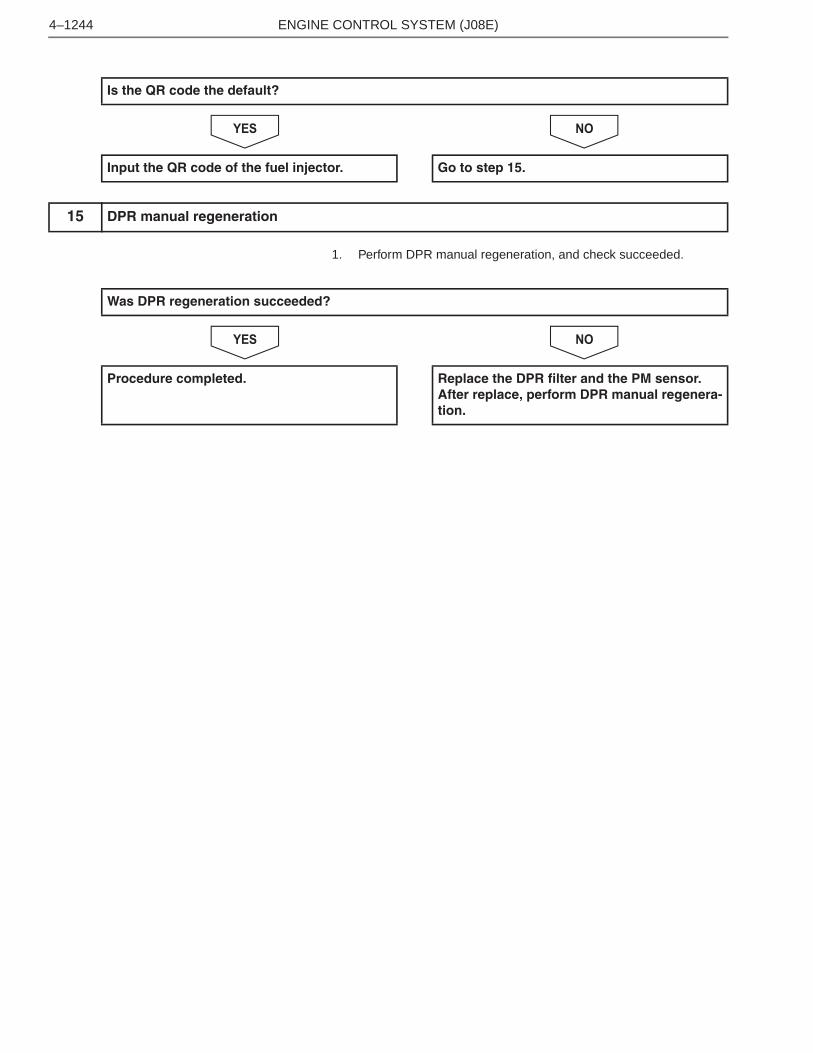
1. Perform DPR manual regeneration, and check succeeded.
NOYES
Is the QR code the default?
Input the QR code of the fuel injector. Go to step 15.
15 DPR manual regeneration
Was DPR regeneration succeeded?
Procedure completed. Replace the DPR filter and the PM sensor.After replace, perform DPR manual regenera-tion.
ENGINE CONTROL SYSTEM (J08E)4–1290
DTC: P24A2EN01H16F01030F03001188
P24A2: Excessive fuel dosing quantityINFORMATION
1. Technical description
<Description of malfunction>
• The engine ECU monitors accumulate post fuel injection quantity at DPR regeneration.
2. DTC set condition(1) DTC detection condition
• While the engine is in operation(2) Judgment criteria
• Accumulate post fuel injection quantity exceeds 2,300 cc.
3. Reset condition
• Immediately after normal status is resumed.
4. Indication, warning or system control regulation when the DTC is set.
• MIL: ON
• SVS light: OFF
• Engine output is restricted.
5. Symptoms on the vehicle when the DTC is set
<Symptoms on the vehicle due to backup control (fail safe function)>
• DPR regeneration prohibited.
• Engine output is insufficient.
<Symptoms on the vehicle due to malfunction>
• –
6. Pre-inspection work
• Check that the battery voltage is in the normal range.
7. After-inspection work
• Clear all past DTCs.
• Check that no DTC is stored after test drive.
8. Estimated failure factors
• Exhaust gas leakage
• DPR filter damage
• Abnormality in fuel injection quantity
• Improper adjustment of exhaust brake valve
• Malfunction of EGR valve
• Malfunction of VNT actuator
• Failure of exhaust gas temperature sensor 4 (DPR inlet)
ENGINE CONTROL SYSTEM (J08E) 4–1291
INSPECTION PROCEDURE: P24A2
1. Set the starter switch to the "LOCK" position.
2. Connect the vehicle to HINO DX .
3. Set the starter switch to the "ON" position.
4. Select [Engine] and check if any below DTC other than P24A2 hasbeen detected.
• P0005, P0006, P0007, P20D8, P20CE
NOYES
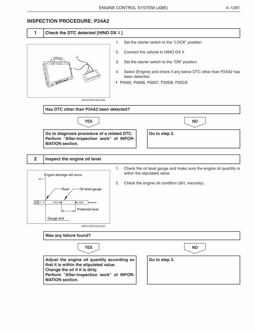
1. Check the oil level gauge and make sure the engine oil quantity iswithin the stipulated value.
2. Check the engine oil condition (dirt, viscosity).
NOYES
1 Check the DTC detected [HINO DX ]
SAPH16F010301422
Has DTC other than P24A2 been detected?
Go to diagnosis procedure of a related DTC.Perform "After-inspection work" of INFOR-MATION section.
Go to step 2.
2 Inspect the engine oil level
Oil level gauge
FULL ADD
Engine damage will occur.
Gauge end
Rivet
Preferred level
SAPH16F010301423
Was any failure found?
Adjust the engine oil quantity according sothat it is within the stipulated value.Change the oil if it is dirty.Perform "After-inspection work" of INFOR-MATION section.
Go to step 3.
ENGINE CONTROL SYSTEM (J08E)4–1292
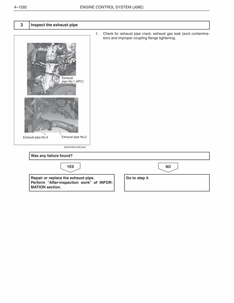
1. Check for exhaust pipe crack, exhaust gas leak (soot contamina-tion) and improper coupling flange tightening.
NOYES
3 Inspect the exhaust pipe
Exhaust pipe No.2Exhaust pipe No.3
Exhaust pipe No.1 (ATC)
SAPH16F010301424
Was any failure found?
Repair or replace the exhaust pipe.Perform "After-inspection work" of INFOR-MATION section.
Go to step 4.
ENGINE CONTROL SYSTEM (J08E) 4–1293
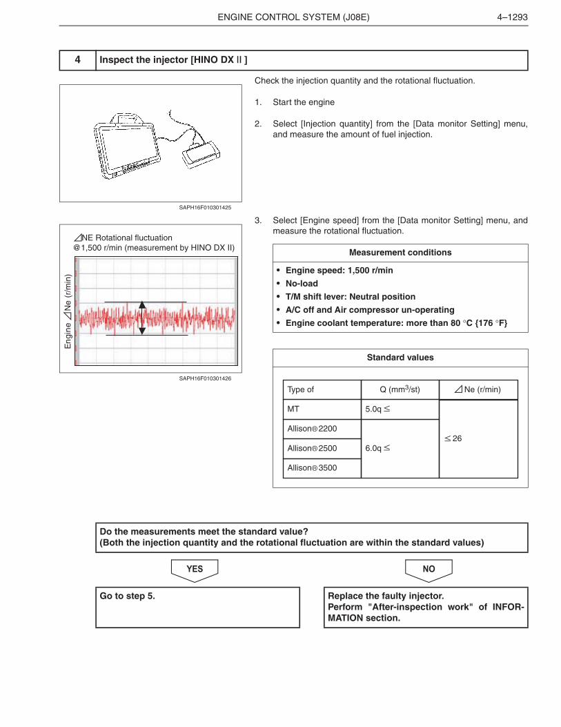
Check the injection quantity and the rotational fluctuation.
1. Start the engine
2. Select [Injection quantity] from the [Data monitor Setting] menu,and measure the amount of fuel injection.
3. Select [Engine speed] from the [Data monitor Setting] menu, andmeasure the rotational fluctuation.
�����
4 Inspect the injector [HINO DX ]
SAPH16F010301425
En
gin
e
Ne
(r/
min
)
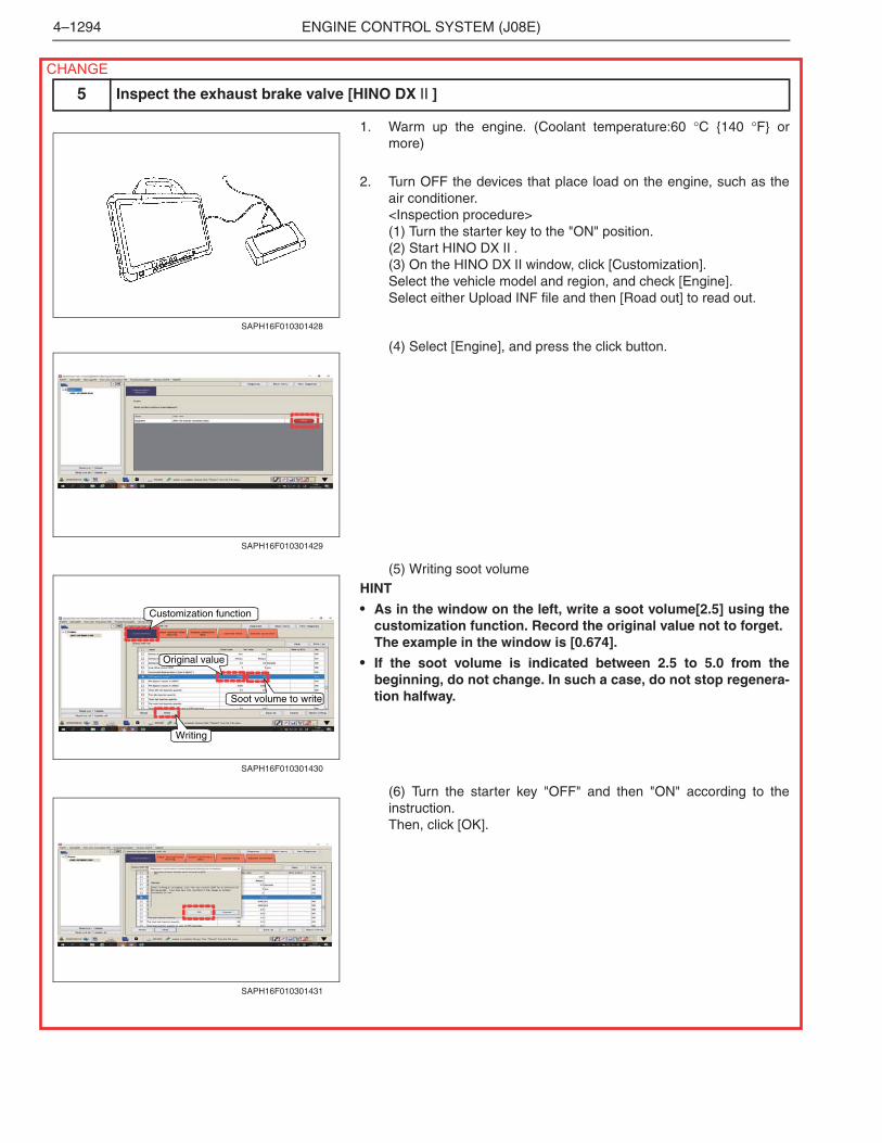
NE Rotational fluctuation@1,500 r/min (measurement by HINO DX II)
SAPH16F010301426
Measurement conditions
• Engine speed: 1,500 r/min
• No-load
• T/M shift lever: Neutral position
• A/C off and Air compressor un-operating
• Engine coolant temperature: more than 80 �C {176 �F}
Standard values
Type of
MT
Allison 2200
Allison 2500
Allison 3500
Q (mm3/st)
5.0q
6.0q
Ne (r/min)
26
Do the measurements meet the standard value?(Both the injection quantity and the rotational fluctuation are within the standard values)
Go to step 5. Replace the faulty injector.Perform "After-inspection work" of INFOR-MATION section.
ENGINE CONTROL SYSTEM (J08E)4–1294
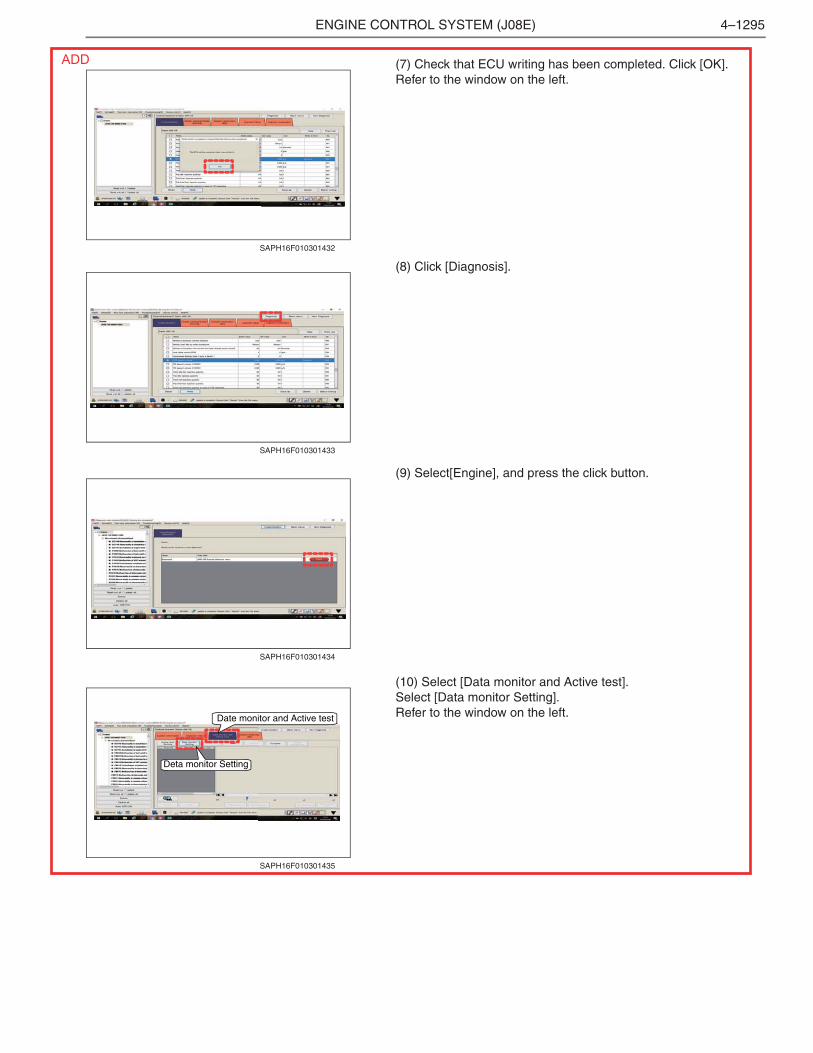
1. Warm up the engine. (Coolant temperature:60 �C {140 �F} ormore)
2. Turn OFF the devices that place load on the engine, such as theair conditioner.<Inspection procedure>(1) Turn the starter key to the "ON" position.(2) Start HINO DX .(3) On the HINO DX window, click [Customization].Select the vehicle model and region, and check [Engine].Select either Upload INF file and then [Road out] to read out.
(4) Select [Engine], and press the click button.
(5) Writing soot volumeHINT
• As in the window on the left, write a soot volume[2.5] using thecustomization function. Record the original value not to forget.The example in the window is [0.674].
• If the soot volume is indicated between 2.5 to 5.0 from thebeginning, do not change. In such a case, do not stop regenera-tion halfway.
(6) Turn the starter key "OFF" and then "ON" according to theinstruction.Then, click [OK].
5 Inspect the exhaust brake valve [HINO DX ]
SAPH16F010301428
SAPH16F010301429
Soot volume to write
Original value
Customization function
Writing
SAPH16F010301430
SAPH16F010301431
CHANGE
ENGINE CONTROL SYSTEM (J08E) 4–1295
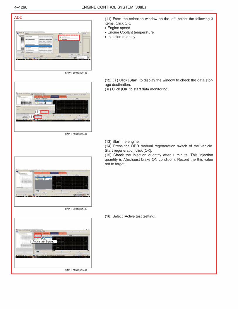
(7) Check that ECU writing has been completed. Click [OK].Refer to the window on the left.
(8) Click [Diagnosis].
(9) Select[Engine], and press the click button.
(10) Select [Data monitor and Active test].Select [Data monitor Setting].Refer to the window on the left.
SAPH16F010301432
SAPH16F010301433
SAPH16F010301434
Date monitor and Active test
Deta monitor Setting
SAPH16F010301435
ADD
ENGINE CONTROL SYSTEM (J08E)4–1296
(11) From the selection window on the left, select the following 3items. Click OK.� Engine speed� Engine Coolant temperature� Injection quantity
(12) ( i ) Click [Start] to display the window to check the data stor-age destination.( ii ) Click [OK] to start data monitoring.
(13) Start the engine.(14) Press the DPR manual regeneration switch of the vehicle.Start regeneration.click [OK].(15) Check the injection quantity after 1 minute. This injectionquantity is A(exhaust brake ON condition). Record the this valuenot to forget.
(16) Select [Active test Setting].
SAPH16F010301436
( i )( ii )
SAPH16F010301437
SAPH16F010301438
Active test Setting
SAPH16F010301439
ADD
ENGINE CONTROL SYSTEM (J08E) 4–1297
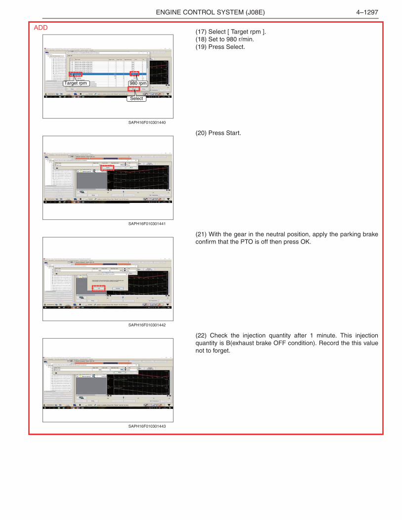
(17) Select [ Target rpm ].(18) Set to 980 r/min.(19) Press Select.
(20) Press Start.
(21) With the gear in the neutral position, apply the parking brakeconfirm that the PTO is off then press OK.
(22) Check the injection quantity after 1 minute. This injectionquantity is B(exhaust brake OFF condition). Record the this valuenot to forget.
Target rpm 980 rpm
Select
SAPH16F010301440
SAPH16F010301441
SAPH16F010301442
SAPH16F010301443
ADD
ENGINE CONTROL SYSTEM (J08E)4–1298
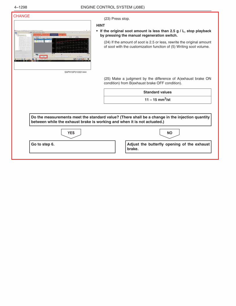
(23) Press stop.
HINT
• If the original soot amount is less than 2.5 g / L, stop playbackby pressing the manual regeneration switch.
(24) If the amount of soot is 2.5 or less, rewrite the original amountof soot with the customization function of (5) Writing soot volume.
(25) Make a judgment by the difference of A(exhaust brake ONcondition) from B(exhaust brake OFF condition).
NOYES
SAPH16F010301444
Standard values
11 – 15 mm3/st
Do the measurements meet the standard value? (There shall be a change in the injection quantitybetween while the exhaust brake is working and when it is not actuated.)
Go to step 6. Adjust the butterfly opening of the exhaustbrake.
CHANGE
ENGINE CONTROL SYSTEM (J08E) 4–1299
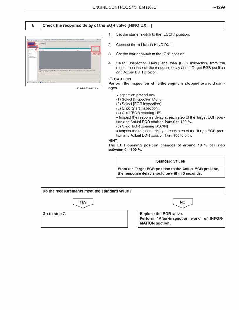
1. Set the starter switch to the "LOCK" position.
2. Connect the vehicle to HINO DX .
3. Set the starter switch to the "ON" position.
4. Select [Inspection Menu] and then [EGR inspection] from themenu, then inspect the response delay at the Target EGR positionand Actual EGR position.
! CAUTION
Perform the inspection while the engine is stopped to avoid dam-ages.
<Inspection procedure>(1) Select [Inspection Menu].(2) Select [EGR inspection].(3) Click [Start inspection].(4) Click [EGR opening UP]:� Inspect the response delay at each step of the Target EGR posi-tion and Actual EGR position from 0 to 100 %.(5) Click [EGR opening DOWN]:� Inspect the response delay at each step of the Target EGR posi-tion and Actual EGR position from 100 to 0 %.
HINTThe EGR opening position changes of around 10 % per stepbetween 0 – 100 %.
NOYES
6 Check the response delay of the EGR valve [HINO DX ]
(1)
(3)(4)(5)
(2)
SAPH16F010301445
Standard values
From the Target EGR position to the Actual EGR position, the response delay should be within 5 seconds.
Do the measurements meet the standard value?
Go to step 7. Replace the EGR valve.Perform "After-inspection work" of INFOR-MATION section.
ENGINE CONTROL SYSTEM (J08E)4–1300
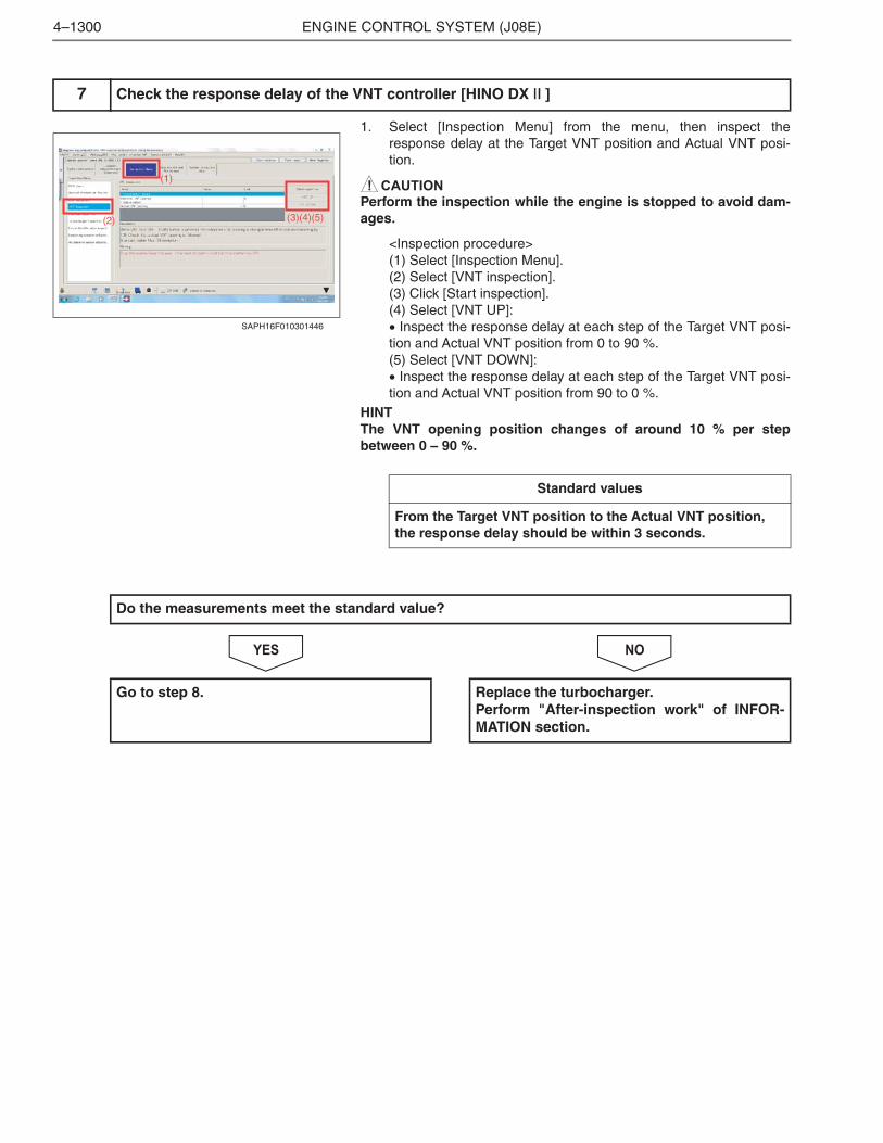
1. Select [Inspection Menu] from the menu, then inspect theresponse delay at the Target VNT position and Actual VNT posi-tion.
! CAUTION
Perform the inspection while the engine is stopped to avoid dam-ages.
<Inspection procedure>(1) Select [Inspection Menu].(2) Select [VNT inspection].(3) Click [Start inspection].(4) Select [VNT UP]:� Inspect the response delay at each step of the Target VNT posi-tion and Actual VNT position from 0 to 90 %.(5) Select [VNT DOWN]:� Inspect the response delay at each step of the Target VNT posi-tion and Actual VNT position from 90 to 0 %.
HINTThe VNT opening position changes of around 10 % per stepbetween 0 – 90 %.
NOYES
7 Check the response delay of the VNT controller [HINO DX ]
(1)
(3)(4)(5)(2)
SAPH16F010301446
Standard values
From the Target VNT position to the Actual VNT position, the response delay should be within 3 seconds.
Do the measurements meet the standard value?
Go to step 8. Replace the turbocharger.Perform "After-inspection work" of INFOR-MATION section.
ENGINE CONTROL SYSTEM (J08E) 4–1301
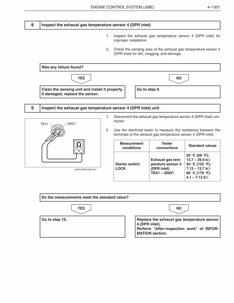
1. Inspect the exhaust gas temperature sensor 4 (DPR inlet) forimproper installation.
2. Check the sensing area of the exhaust gas temperature sensor 4(DPR inlet) for dirt, clogging, and damage.
NOYES
1. Disconnect the exhaust gas temperature sensor 4 (DPR inlet) con-nector.
2. Use the electrical tester to measure the resistance between theterminals of the exhaust gas temperature sensor 4 (DPR inlet).
NOYES
8 Inspect the exhaust gas temperature sensor 4 (DPR inlet)
Was any failure found?
Clean the sensing unit and install it properly.If damaged, replace the sensor.
Go to step 9.
9 Inspect the exhaust gas temperature sensor 4 (DPR inlet) unit
GND1TEX1
SAPH16F010301447
Measurementconditions
Tester connections
Standard values
Starter switch: LOCK
Exhaust gas tem-perature sensor 4 (DPR inlet)TEX1 – GND1
20 �C {68 �F}:13.7 – 29.8 k�50 �C {122 �F}: 7.13 – 13.7 k�80 �C {176 �F}: 4.1 – 7.13 k�
Do the measurements meet the standard value?
Go to step 10. Replace the exhaust gas temperature sensor4 (DPR inlet).Perform "After-inspection work" of INFOR-MATION section.
ENGINE CONTROL SYSTEM (J08E)4–1302
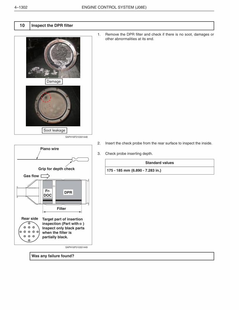
1. Remove the DPR filter and check if there is no soot, damages orother abnormalities at its end.
2. Insert the check probe from the rear surface to inspect the inside.
3. Check probe inserting depth.
10 Inspect the DPR filter
Damage
Soot leakage
SAPH16F010301448
Piano wire
Grip for depth check
Gas flow
Fr-DOC
DPR
Filter
Rear side Target part of insertion inspection (Part with )Inspect only black parts when the filter is partially black.
SAPH16F010301449
Standard values
175 - 185 mm {6.890 - 7.283 in.}
Was any failure found?
ENGINE CONTROL SYSTEM (J08E) 4–1303
NOYES
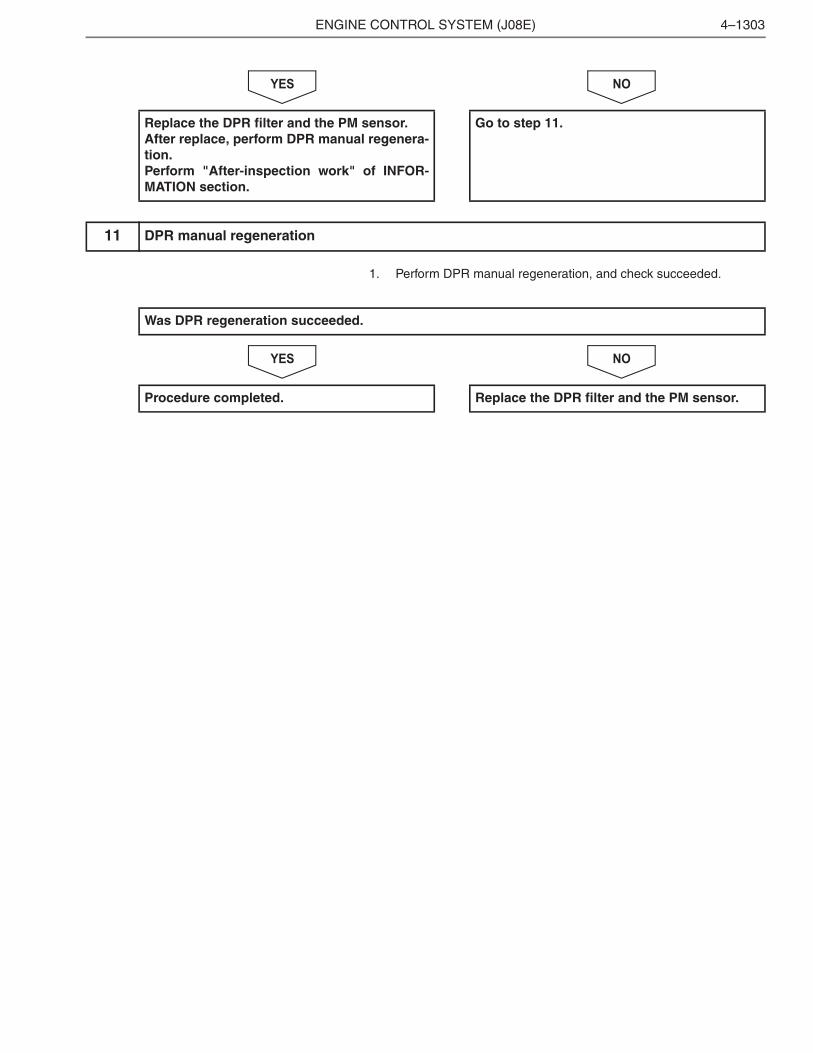
1. Perform DPR manual regeneration, and check succeeded.
NOYES
Replace the DPR filter and the PM sensor.After replace, perform DPR manual regenera-tion.Perform "After-inspection work" of INFOR-MATION section.
Go to step 11.
11 DPR manual regeneration
Was DPR regeneration succeeded.
Procedure completed. Replace the DPR filter and the PM sensor.