Embed Size (px)
Citation preview

LCD TVSERVICE MANUAL
CAUTIONBEFORE SERVICING THE CHASSIS,READ THE SAFETY PRECAUTIONS IN THIS MANUAL.
CHASSIS : ML-027C
MODEL : RU-23LZ21
website:http://biz.LGservice.come-mail:http://www.LGEservice.com/techsup.html
Oct.,2003Printed in KoreaP/NO : 3828VD0140K
MONO DPMSTEREO
ST DUAL
- 2 -
PRODUCT SAFETY
IMPORTANT SAFETY NOTICEThis manual was prepared for use only by properly trained audiovisual servicetechnicians. When servicing this product, under no circumstances should theoriginal design be modified or altered without permission from ZenithElectronics Corporation. All components should be replaced only with typesidentical to those in the original circuit and their physical location, wiring, andlead dress must conform to original layout upon completion of repairs. If anyfuse (or Fusible Resistor) in this TV receiver is blown, replace it only with thefactory specified fuse type and rating. When replacing a high wattage resistor(Oxide Metal Film Resistor, over 1W), keep the resistor 10mm away from PCB.Always keep wires away from high voltage or high temperature parts.
Special components are also used to prevent shock and fire hazard.These components are indicated by the letter “x” included in their componentdesignators and are required to maintain safe performance. No deviations areallowed without prior approval by Zenith Electronics Corporation. Service workshould be performed only after you are thoroughly familiar with these safetychecks and servicing guidelines.
Circuit diagrams may occasionally differ from the actual circuit used.This way, implementation of the latest safety and performance improvementchanges into the set is not delayed until the new service literature is printed.
CAUTION: Do not attempt to modify this product in any way. Never perform customized installations without manufacturer’sapproval.Unauthorized modifications will not only void the warranty, but maylead to property damage or user injury.
GENERAL GUIDANCEAn lsolation Transformer should always be used during the servicingof a receiver whose chassis is not isolated from the AC power line. Use atransformer of adequate power rating to protect against personal injury fromelectrical shocks. It will also protect the receiver and its components from beingdamaged by accidental shorts of the circuitry that may be inadvertentlyintroduced during the service operation.
Before returning the receiver to the customer, always perform an AC leakagecurrent check on the exposed metallic parts of the cabinet, such as antennas,terminals, etc., to be sure the set is safe to operatewithout damage of electrical shock.
LEAKAGE CURRENT COLD CHECK(ANTENNA COLD CHECK)With the instrument’s AC plug removed from AC source, connect an electricaljumper across the two AC plug prongs. Place the AC switch in the on position,connect one lead of ohm-meter to the AC plug prongs tied together, and touchother ohm-meter lead in turn to each exposed metallic parts such as antennaterminals, phone jacks, etc. If the exposed metallic part has a return path to thechassis, the measured resistance should be between 1MΩ and 5.2MΩ. Whenthe exposed metal has no return path to the chassis the reading must beinfinite. Any other abnormality that exists must be corrected beforethe receiver is returned to the customer.
ELECTROSTATICALLY SENSITIVE DEVICESSome semiconductor (solid-state) devices can be damaged easily by staticelectricity. Such components commonly are called Electrostatically Sensitive(ES) Devices. Examples of typical ES devices are integrated circuits and somefield-effect transistors and semiconductor “chip” components. The followingtechniques should be used to help reduce the incidence of component damagecaused by static electricity.
1. Immediately before handling any semiconductor component orsemiconductor-equipped assembly, drain off any electrostatic charge on thebody by touching a known earth ground. Alternatively, obtain and wear acommercially available discharging wrist strap device, which should beremoved for potential shock reasons prior to applying power to the unit undertest.
2. After removing an electrical assembly equipped with ES devices, place theassembly on a conductive surface such as an ESD mat, to preventelectrostatic charge buildup or exposure of the assembly.
3. Use only a grounded-tip soldering iron to solder or unsolder ES devices.4. Use only an anti-static solder removal device. Some solder removal devices
not classified as “anti-static” can generate electrical charges sufficient todamage ES devices.
5. Do not use freon-propelled chemicals. These can generate electrical chargesufficient to damage ES devices.
6. Do not remove a replacement ES device from its protective package untilimmediately before you are ready to install it. (Most replacement ES devicesare packaged with leads electrically shorted together by conductive foam,aluminum foil, or comparable conductive material.)
7. Immediately before removing the protective material from the leads of areplacement ES device, touch the protective material to the chassis or circuitassembly into which the device will be installed.
Caution: Be sure no power is applied to the chassis or circuit, and observeall other safety precautions.
8. Minimize bodily motions when handling unpackaged replacement ESdevices. (Otherwise, seemingly harmless motion, such as the brushingtogether of your clothing or the lifting of your foot from a carpeted floor, cangenerate static electricity sufficient to damage an ES device.)
REGULATORY INFORMATIONThis equipment has been tested and found to comply with the limits for a ClassB digital device, pursuant to Part 15 of the FCC Rules.These limits are designed to provide reasonable protection against harmfulinterference when the equipment is operated in a residential installation. Thisequipment generates, uses and can radiate radio frequency energy and, if notinstalled and used in accordance with the instruction manual, may causeharmful interference to radio communications. However, there is no guaranteethat interference will not occur in a particular installation. If this equipment doescause harmful interference to radio or television reception, which can bedetermined by turning the equipment off and on, the user is encouraged to tryto correct the interference by one or more of the following measures: Reorientor relocate the receiving antenna; Increase the separation between theequipment and receiver; Connect the equipment into an outlet on a circuitdifferent from that to which the receiver is connected; Consult the dealer or anexperienced radio/TV technician for help.
The responsible party for this device’s compliance is:
Zenith Electronics Corporation201 James Record RoadHuntsville, AL 35824, USADigital TV Hotline: 1-877-993-6484

- 3 -
SPECIFICATIONS.................................................................4
DESCRIPTION OF CONTROLS...........................................5
ADJUSTMENT INSTRUCTIONS ..........................................7
TROUBLESHOOTING ........................................................10
PRINTED CIRCUIT BOARD ...............................................11
BLOCK DIAGRAM...............................................................15
EXPLODED VIEW...............................................................16
EXPLODED VIEW PARTS LIST .........................................17
REPLACEMENT PARTS LIST............................................18
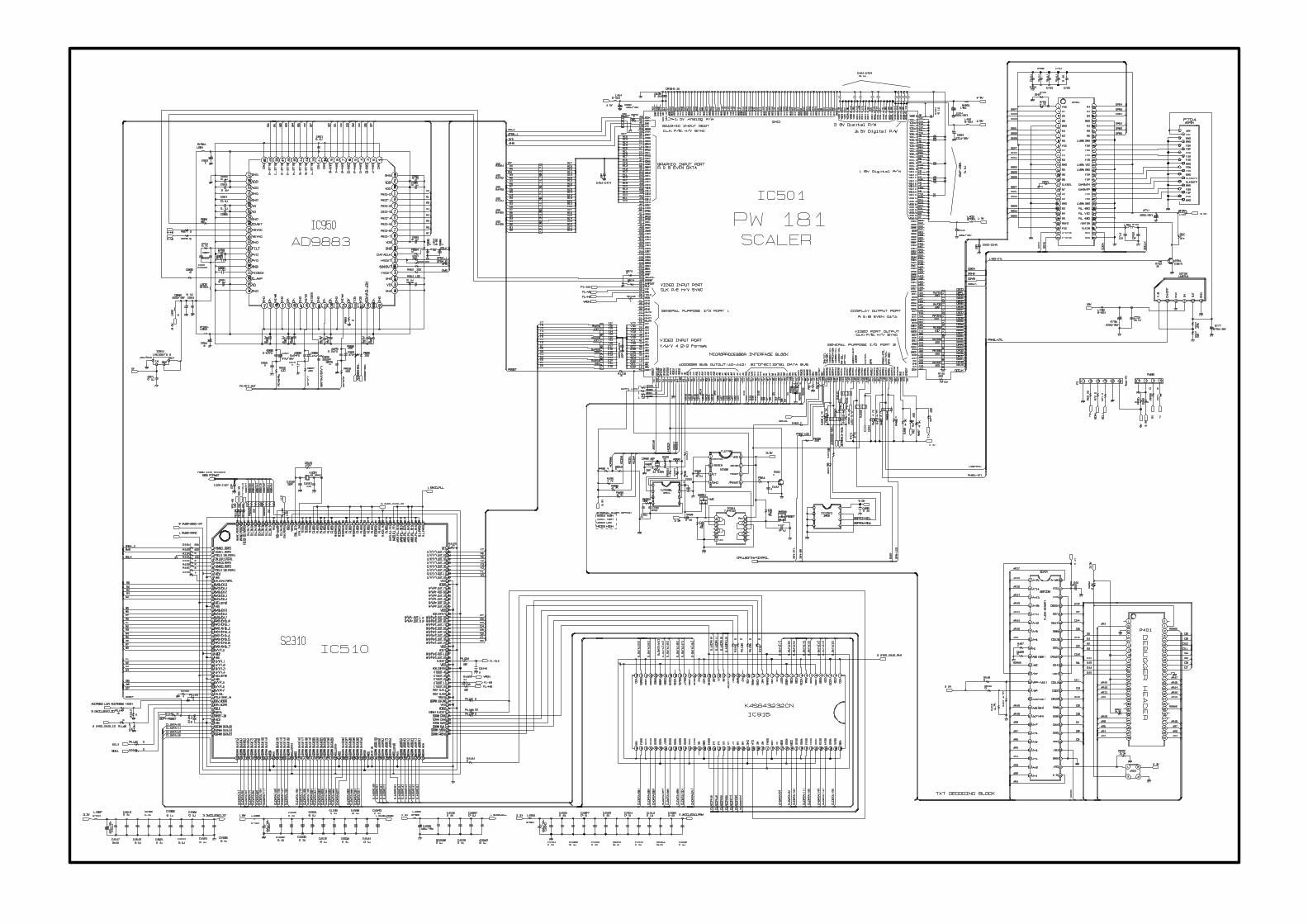
SCHEMATIC DIAGRAM..........................................................
TABLE OF CONTENTS

- 4 -
SPECIFICATIONS

- 5 -
DESCRIPTION OF CONTROLS
Controls & Connection OptionsControls & Connection Options
Remote Control Sensor
DPM Indicator
SAP IndicatorMono Indicator
Power/Standby IndicatorGlows red in Standby mode,Glows green when the TV is turned on.
Stereo Indicator
Headphone Jack
S-Video Input
Video Input
Audio Input
AC Input
DVD/DTV Input(Component (480i/480p/720p/1080i), Audio)
Audio / Video Input
PC Sound Input
PC Input
Antenna Input
Channel Buttons
Volume Buttons
ch
vol
menu
enter
on/off
tv
video
/ I
Enter Button
Menu Button
TV/Video Button
On/Off Button

- 6 -
- When using the remote control, aim it at the remote control sensor on the TV.
powermute
tv/video multimedia mts
fcr
ch
ch
vol
enter
1 2 3
4 5 6
7 8 9
0
vol
exit menu
audio
piparc cc
video
pip input flashbkposition
pip swap sleepsize
still
scan ch
MUTESwitches the sound on or off.
PIPPOSITIONPIP INPUT
SIZEPIP SWAP
STILLSCAN
CH (DD / EE)
ENTER
CH DD / EE (Channel button)
VOL FF / GG (Volume button)
POWER
MTS
EXIT
MENU
MULTIMEDIASelects: TV, Component, or RGB-PC mode.
VIDEO
CC
FLASHBKPress the FLASHBK button toreturn to the last channel you werewatching.
SLEEP
AUDIO
ARC
TV/VIDEOSelects: TV, Video 1, Video 2, S-
Video, Component, or RGB-PCmode.
FCR
NUMBER buttons
Remote Control Key FunctionsRemote Control Key Functions
DESCRIPTION OF CONTROLS
- 7 -
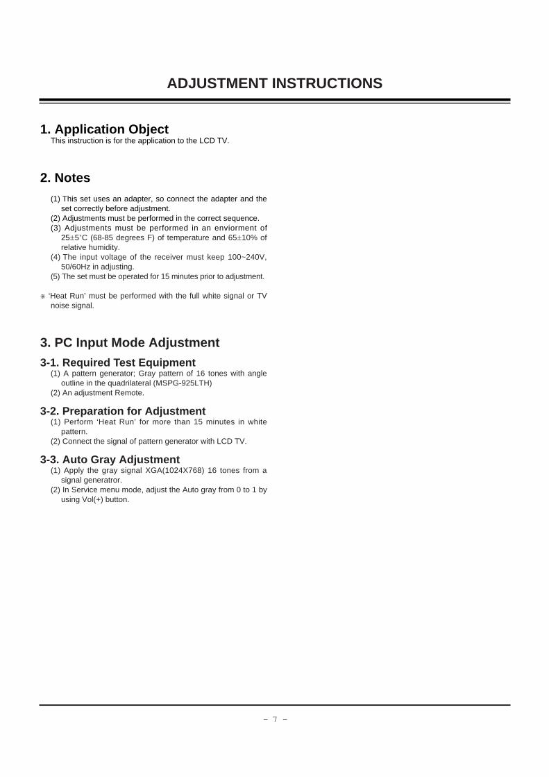
1. Application ObjectThis instruction is for the application to the LCD TV.
2. Notes
(1) This set uses an adapter, so connect the adapter and theset correctly before adjustment.
(2) Adjustments must be performed in the correct sequence.(3) Adjustments must be performed in an enviorment of
25!5cC (68-85 degrees F) of temperature and 65!10% ofrelative humidity.
(4) The input voltage of the receiver must keep 100~240V,50/60Hz in adjusting.
(5) The set must be operated for 15 minutes prior to adjustment.
[ ‘Heat Run’ must be performed with the full white signal or TVnoise signal.
3. PC Input Mode Adjustment
3-1. Required T est Equipment(1) A pattern generator; Gray pattern of 16 tones with angle
outline in the quadrilateral (MSPG-925LTH)(2) An adjustment Remote.
3-2. Preparation for Adjustment(1) Perform ‘Heat Run’ for more than 15 minutes in white
pattern.(2) Connect the signal of pattern generator with LCD TV.
3-3. Auto Gray Adjustment(1) Apply the gray signal XGA(1024X768) 16 tones from a
signal generatror.(2) In Service menu mode, adjust the Auto gray from 0 to 1 by
using Vol(+) button.
ADJUSTMENT INSTRUCTIONS

- 8 -
ADJUSTMENT INSTRUCTIONS
4. Position Adjustment
Mode
H_Display
V_Display
V_Frequency
H_Total
H_Blanking
H_Sync
H_Polarity
H_Vp
H_Fp
H-Freq[KHz]
/Clk[MHz]
V_Total
V_Blanking
V_Sync
V_Polarity
V_Bp
V_Fp
VGA-60
640
480
60
800
160
96
NEG.
48
16
31.469
25.175
525
45
2
NEG
33
10
VGA-67
640
480
67
864
224
64
NEG.
96
64
35.0
30.24
525
45
3
NEG
39
3
VGA-75
640
480
75
840
200
64
NEG
120
16
37.5
31.5
500
20
3
NEG
16
1
VGA-85
640
480
82
832
192
56
NEG
80
56
43.269
36.0
509
29
3
NEG
25
1
SVGA-56
800
600
56
1024
224
72
POS
128
24
35.156
36.0
62.5
25
2
POS
22
1
SVGA-60
800
600
60
1056
256
128
POS
88
40
37.879
40.0
628
28
4
POS
23
1
SVGA-72
800
600
72
1040
240
120
POS
64
56
48.077
50.0
666
66
6
POS
23
37
Mode
H_Display
V_Display
V_Frequency
H_Total
H_Blanking
H_Sync
H_Polarity
H_Vp
H_Fp
H-Freq[KHz]
/Clk[MHz]
V_Total
V_Blanking
V_Sync
V_Polarity
V_Bp
V_Fp
SVGA-75
800
600
75
1056
256
80
POS
160
16
46.875
49.5
625
25
3
POS
21
1
SVGA-
85800
600
85
1048
248
64
POS
152
32
53.674
56.25
631
31
3
POS
27
1
XGA-60
1024
768
60
1344
320
136
NEG
136
160
48.363
65.0
806
38
6
NEG
29
3
XGA-70
1024
768
70
1328
304
136
NEG
144
24
56.476
75.0
806
38
6
NEG
29
3
XGA-75
1024
768
75
1312
288
96
POS
176
16
60.023
78.75
800
32
3
POS
28
1
XGA-85
1024
768
82
1376
352
96
POS
208
48
68.677
84.997
808
40
3
POS
36
1
WXGA-50
1280
768
50
1648
368
128
NEG
184
56
39.518
65.125
791
23
7
POS
15
1
WXGA-60
1280
768
60
1680
400
136
NEG
200
64
47.693
80.125
795
27
7
POS
19
1

- 9 -
ADJUSTMENT INSTRUCTIONS
5. EDID (The Extended Display Identification Data)
EDID Table
00
10
20
30
40
50
60
70
00 01 02 03 04 05 06 07 08 09 0A 0B 0C 0D 0E 0F
00
00
14
81
01
01
26
00
FF
0B
50
40
01
01
30
32
FF
01
54
81
01
01
18
55
FF
01
BF
80
01
01
88
1E
FF
78
E8
01
01
01
36
46
FF
1F
80
01
01
01
00
0D
FF
17
31
10
01
01
0E
00
00
70
59
0E
01
01
C3
0A
30
E8
3B
01
F9
01
10
20
E5
C3
D9
01
15
01
00
20
D7
A0
45
01
01
64
00
20
3A
A3
59
01
01
19
1E
20
01
54
61
01
01
00
00
20
00
4C
59
01
01
40
00
20
00
97
71
01
01
41
00
00
00
24
59
01
01
00
FD
C8
- 10 -
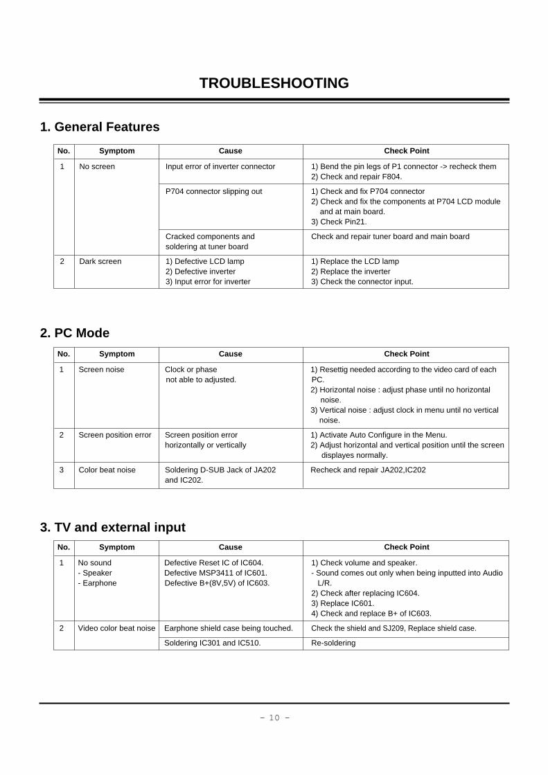
TROUBLESHOOTING
1 No sound Defective Reset IC of IC604. 1) Check volume and speaker.- Speaker Defective MSP3411 of IC601. - Sound comes out only when being inputted into Audio - Earphone Defective B+(8V,5V) of IC603. L/R.
2) Check after replacing IC604.3) Replace IC601.4) Check and replace B+ of IC603.
2 Video color beat noise Earphone shield case being touched. Check the shield and SJ209, Replace shield case.
Soldering IC301 and IC510. Re-soldering
1 No screen Input error of inverter connector 1) Bend the pin legs of P1 connector -> recheck them2) Check and repair F804.
P704 connector slipping out 1) Check and fix P704 connector2) Check and fix the components at P704 LCD module
and at main board.3) Check Pin21.
Cracked components and Check and repair tuner board and main boardsoldering at tuner board
2 Dark screen 1) Defective LCD lamp 1) Replace the LCD lamp2) Defective inverter 2) Replace the inverter3) Input error for inverter 3) Check the connector input.
1. General Features
2. PC Mode
No. Symptom Cause Check Point
No. Symptom Cause Check Point
Check Point
1 Screen noise Clock or phase 1) Resettig needed according to the video card of eachnot able to adjusted. PC.
2) Horizontal noise : adjust phase until no horizontalnoise.
3) Vertical noise : adjust clock in menu until no vertical noise.
2 Screen position error Screen position error 1) Activate Auto Configure in the Menu.horizontally or vertically 2) Adjust horizontal and vertical position until the screen
displayes normally.
3 Color beat noise Soldering D-SUB Jack of JA202 Recheck and repair JA202,IC202and IC202.
3. TV and external inputNo. Symptom Cause
- 11 -
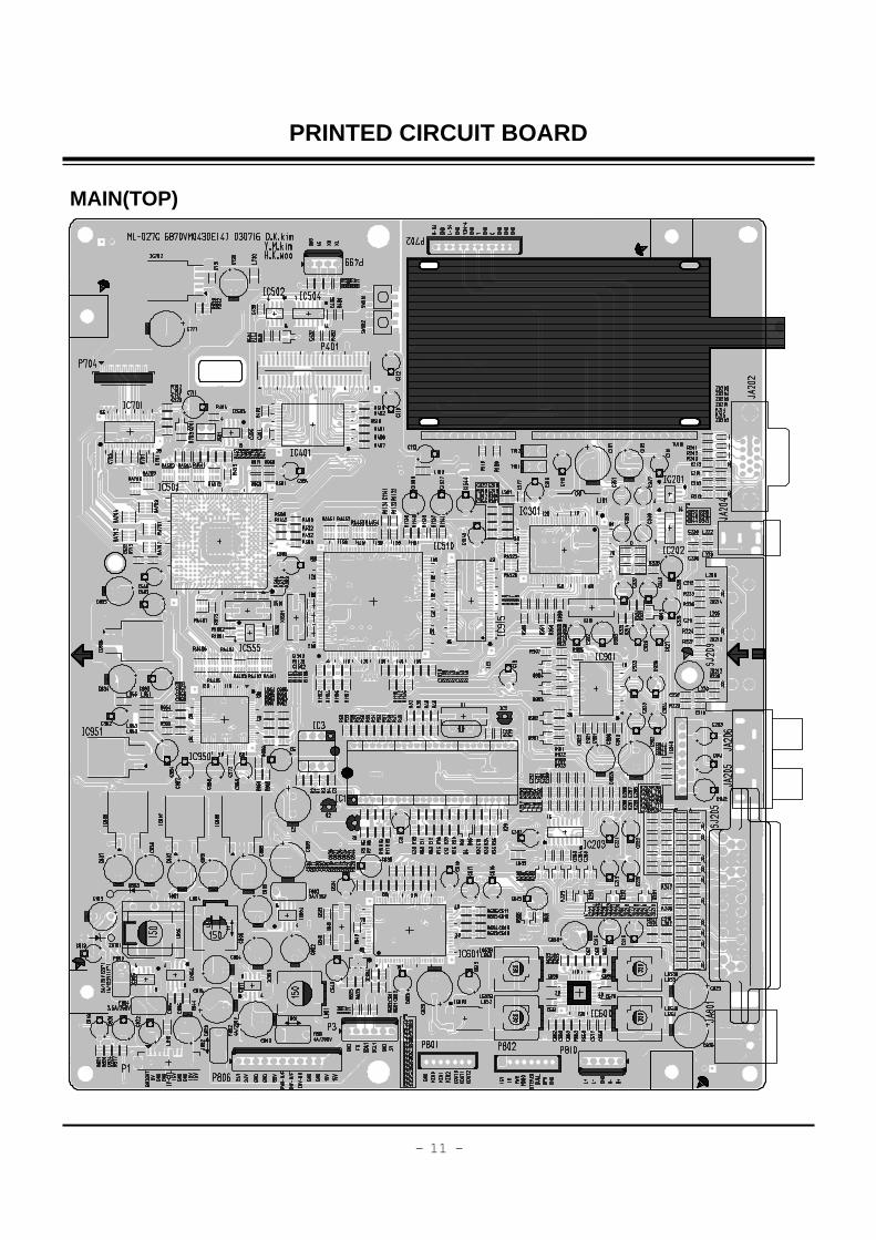
PRINTED CIRCUIT BOARD
MAIN(TOP)

- 12 -
PRINTED CIRCUIT BOARD
MAIN(BOTTOM)

- 13 -
PRINTED CIRCUIT BOARD
POWER
- 14 -
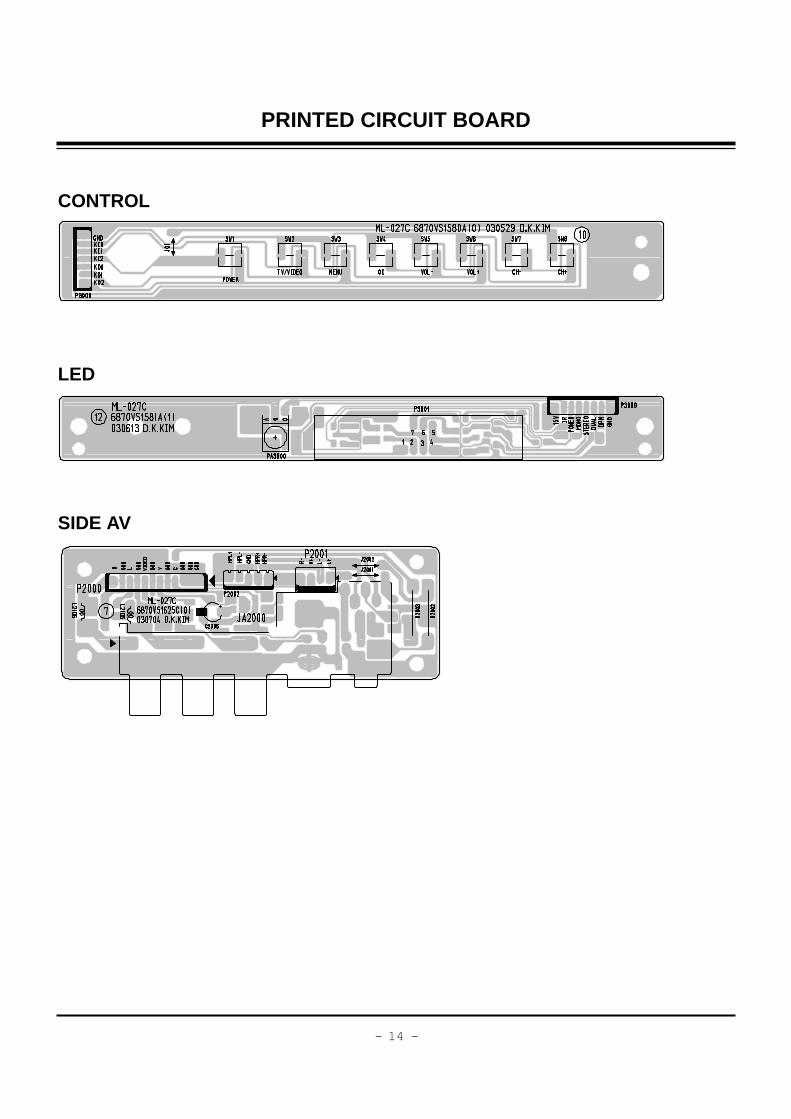
PRINTED CIRCUIT BOARD
CONTROL
LED
SIDE AV

- 15 -
BLOCK DIAGRAM

- 16 -
EXPLODED VIEW
250
112
520 55
0
500
320
210
220
310
400
430
230
240
530 56
0
300
120
120
340
350
330
360
370
380
330

- 17 -
112 6306V23001A LCD MODULE,LC230W01-A2 LG TFT COLOR 23 WXGA LCD MODULE
120 6400GKTX01B SPEAKER,FULLRANGE F1527C-6428-2 8OHM 7/12W 85DB OTHERS
210 4950V00151B METAL,SHIELD ET .
230 4810V00765F BRACKET,SIDE AV RU-15LA61 ML012C HIPS 40AF .
240 4950V00142A METAL,SHIELD NON SIDE AV, 20LA60/15LA60
250 4950V00149C METAL,FRAME SECC(EGI) .
300 3091V00518F CABINET ASSEMBLY,RU-23LZ21 STEREO ML027C .
310 5020V00781B BUTTON,CONTROL RU-23LZ21 ABS, HF-380 8KEY .
320 4950V00150A METAL,SHIELD SBHG RZ-23LZ20
330 4950V00157D METAL,HINGE ASSY SPCC(CR) RZ-23LZ20
340 4810V00767C BRACKET,STAND RU-20LA61 NON ABS, HF-380 HINGE FRONT
350 4810V00768C BRACKET,STAND RU-20LA61 NON ABS, HF-380 HINGE REAR
360 4810V00766C BRACKET,STAND RU-20LA61 NON ABS, HF-380 DECO
370 4810V00769C BRACKET,STAND RU-20LA61 NON ABS, HF-380 BASE
380 4950V00133A METAL,STAND NON BASE 20LA60
400 3809V00359J BACK COVER ASSEMBLY,RU-23LZ21 NON .
430 3500V00068B BOARD,AV RU-23LZ21 ML027C .
520 6871VMMQ43A PWB(PCB) ASSEMBLY,MAIN ML-027C RU-23LZ20
530 6871VSMW11A PWB(PCB) ASSEMBLY,SUB CONT ML027C MANNUAL ASSY
540 6871VSMW07A PWB(PCB) ASSEMBLY,SUB POWER ML027C ASSY
550 6871VSMV40P PWB(PCB) ASSEMBLY,SUB A/V ML027C RU-23LZ21
560 6871VSMW12B PWB(PCB) ASSEMBLY,SUB WINDO ML027C INDEX MANNUAL ASSY
EXPLODED VIEW PARTS LIST
No. PART NO. DESCRIPTION
- 18 -
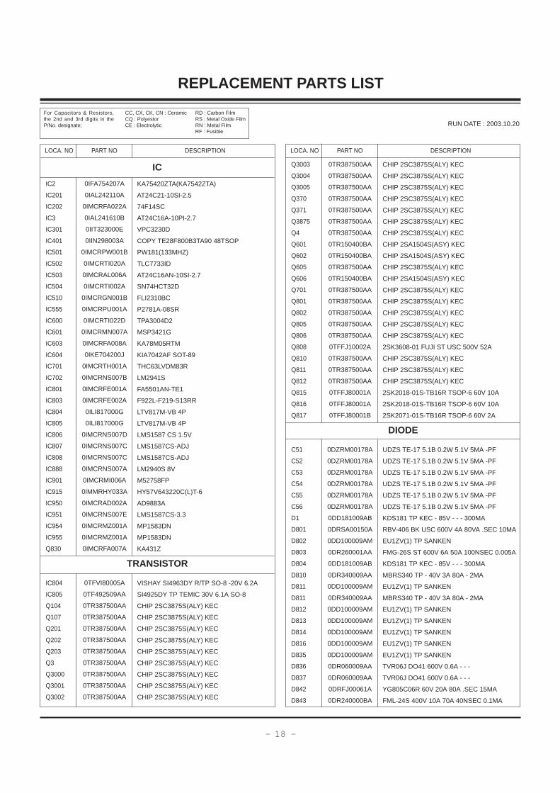
REPLACEMENT PARTS LIST
LOCA. NO PART NO DESCRIPTION
Q3003
Q3004
Q3005
Q370
Q371
Q3875
Q4
Q601
Q602
Q605
Q606
Q701
Q801
Q802
Q805
Q806
Q808
Q810
Q811
Q812
Q815
Q816
Q817
C51
C52
C53
C54
C55
C56
D1
D801
D802
D803
D804
D810
D811
D811
D812
D813
D814
D816
D835
D836
D837
D842
D843
0TR387500AA
0TR387500AA
0TR387500AA
0TR387500AA
0TR387500AA
0TR387500AA
0TR387500AA
0TR150400BA
0TR150400BA
0TR387500AA
0TR150400BA
0TR387500AA
0TR387500AA
0TR387500AA
0TR387500AA
0TR387500AA
0TFFJ10002A
0TR387500AA
0TR387500AA
0TR387500AA
0TFFJ80001A
0TFFJ80001A
0TFFJ80001B
0DZRM00178A
0DZRM00178A
0DZRM00178A
0DZRM00178A
0DZRM00178A
0DZRM00178A
0DD181009AB
0DRSA00150A
0DD100009AM
0DR260001AA
0DD181009AB
0DR340009AA
0DD100009AM
0DR340009AA
0DD100009AM
0DD100009AM
0DD100009AM
0DD100009AM
0DD100009AM
0DR060009AA
0DR060009AA
0DRFJ00061A
0DR240000BA
CHIP 2SC3875S(ALY) KEC
CHIP 2SC3875S(ALY) KEC
CHIP 2SC3875S(ALY) KEC
CHIP 2SC3875S(ALY) KEC
CHIP 2SC3875S(ALY) KEC
CHIP 2SC3875S(ALY) KEC
CHIP 2SC3875S(ALY) KEC
CHIP 2SA1504S(ASY) KEC
CHIP 2SA1504S(ASY) KEC
CHIP 2SC3875S(ALY) KEC
CHIP 2SA1504S(ASY) KEC
CHIP 2SC3875S(ALY) KEC
CHIP 2SC3875S(ALY) KEC
CHIP 2SC3875S(ALY) KEC
CHIP 2SC3875S(ALY) KEC
CHIP 2SC3875S(ALY) KEC
2SK3608-01 FUJI ST USC 500V 52A
CHIP 2SC3875S(ALY) KEC
CHIP 2SC3875S(ALY) KEC
CHIP 2SC3875S(ALY) KEC
2SK2018-01S-TB16R TSOP-6 60V 10A
2SK2018-01S-TB16R TSOP-6 60V 10A
2SK2071-01S-TB16R TSOP-6 60V 2A
UDZS TE-17 5.1B 0.2W 5.1V 5MA -PF
UDZS TE-17 5.1B 0.2W 5.1V 5MA -PF
UDZS TE-17 5.1B 0.2W 5.1V 5MA -PF
UDZS TE-17 5.1B 0.2W 5.1V 5MA -PF
UDZS TE-17 5.1B 0.2W 5.1V 5MA -PF
UDZS TE-17 5.1B 0.2W 5.1V 5MA -PF
KDS181 TP KEC - 85V - - - 300MA
RBV-406 BK USC 600V 4A 80VA .SEC 10MA
EU1ZV(1) TP SANKEN
FMG-26S ST 600V 6A 50A 100NSEC 0.005A
KDS181 TP KEC - 85V - - - 300MA
MBRS340 TP - 40V 3A 80A - 2MA
EU1ZV(1) TP SANKEN
MBRS340 TP - 40V 3A 80A - 2MA
EU1ZV(1) TP SANKEN
EU1ZV(1) TP SANKEN
EU1ZV(1) TP SANKEN
EU1ZV(1) TP SANKEN
EU1ZV(1) TP SANKEN
TVR06J DO41 600V 0.6A - - -
TVR06J DO41 600V 0.6A - - -
YG805C06R 60V 20A 80A .SEC 15MA
FML-24S 400V 10A 70A 40NSEC 0.1MA
LOCA. NO PART NO DESCRIPTION
IC2
IC201
IC202
IC3
IC301
IC401
IC501
IC502
IC503
IC504
IC510
IC555
IC600
IC601
IC603
IC604
IC701
IC702
IC801
IC803
IC804
IC805
IC806
IC807
IC808
IC888
IC901
IC915
IC950
IC951
IC954
IC955
Q830
IC804
IC805
Q104
Q107
Q201
Q202
Q203
Q3
Q3000
Q3001
Q3002
0IFA754207A
0IAL242110A
0IMCRFA022A
0IAL241610B
0IIT323000E
0IIN298003A
0IMCRPW001B
0IMCRTI020A
0IMCRAL006A
0IMCRTI002A
0IMCRGN001B
0IMCRPU001A
0IMCRTI022D
0IMCRMN007A
0IMCRFA008A
0IKE704200J
0IMCRTH001A
0IMCRNS007B
0IMCRFE001A
0IMCRFE002A
0ILI817000G
0ILI817000G
0IMCRNS007D
0IMCRNS007C
0IMCRNS007C
0IMCRNS007A
0IMCRMI006A
0IMMRHY033A
0IMCRAD002A
0IMCRNS007E
0IMCRMZ001A
0IMCRMZ001A
0IMCRFA007A
0TFVI80005A
0TF492509AA
0TR387500AA
0TR387500AA
0TR387500AA
0TR387500AA
0TR387500AA
0TR387500AA
0TR387500AA
0TR387500AA
0TR387500AA
KA75420ZTA(KA7542ZTA)
AT24C21-10SI-2.5
74F14SC
AT24C16A-10PI-2.7
VPC3230D
COPY TE28F800B3TA90 48TSOP
PW181(133MHZ)
TLC7733ID
AT24C16AN-10SI-2.7
SN74HCT32D
FLI2310BC
P2781A-08SR
TPA3004D2
MSP3421G
KA78M05RTM
KIA7042AF SOT-89
THC63LVDM83R
LM2941S
FA5501AN-TE1
F922L-F219-S13RR
LTV817M-VB 4P
LTV817M-VB 4P
LMS1587 CS 1.5V
LMS1587CS-ADJ
LMS1587CS-ADJ
LM2940S 8V
M52758FP
HY57V643220C(L)T-6
AD9883A
LMS1587CS-3.3
MP1583DN
MP1583DN
KA431Z
VISHAY SI4963DY R/TP SO-8 -20V 6.2A
SI4925DY TP TEMIC 30V 6.1A SO-8
CHIP 2SC3875S(ALY) KEC
CHIP 2SC3875S(ALY) KEC
CHIP 2SC3875S(ALY) KEC
CHIP 2SC3875S(ALY) KEC
CHIP 2SC3875S(ALY) KEC
CHIP 2SC3875S(ALY) KEC
CHIP 2SC3875S(ALY) KEC
CHIP 2SC3875S(ALY) KEC
CHIP 2SC3875S(ALY) KEC
IC
TRANSISTOR
RUN DATE : 2003.10.20
For Capacitors & Resistors,the 2nd and 3rd digits in theP/No. designate;
CC, CX, CK, CN : CeramicCQ : PolyestorCE : Electrolytic
RD : Carbon FilmRS : Metal Oxide FilmRN : Metal FilmRF : Fusible
DIODE

- 19 -
LOCA. NO PART NO DESCRIPTION
D845
D846
ZD101
ZD203
ZD204
ZD205
ZD206
ZD207
ZD225
ZD3002
ZD650
ZD651
ZD652
ZD801
ZD803
ZD805
ZD806
ZD807
ZD808
ZD809
ZD812
ZD815
ZD816
ZD817
ZD818
C107
C109
C112
C113
C1527
C1532
C1544
C1545
C1599
C19
C2
C2
C216
C219
C220
C2300
C2301
C2305
C301
C303
C305
C31
C315
0DR240000BA
0DR240000BA
0DZ330009DF
0DZRM00178A
0DZRM00178A
0DZRM00178A
0DZRM00178A
0DZRM00178A
0DZRM00178A
0DZRM00178A
0DZRM00178A
0DZRM00178A
0DZRM00178A
0DZ180009AG
0DZ180009AG
0DZ180009AG
0DZ110009AD
0DZ560009CF
0DZ110009AD
0DZ560009CF
0DZ110009AD
0DZ910009AJ
0DZ910009AJ
0DZ910009AJ
0DZ110009AD
0CE108DD618
0CE106DK618
0CE476DF618
0CE107DF618
0CE107DF618
0CE107DF618
0CE476DF618
0CE107DD618
0CE107DD618
0CE106DF618
0CE107DF618
0CE687DD618
0CE106DF618
0CE106DF618
0CE106DF618
0CK105DF64A
0CK105DF64A
0CE225DK618
0CK224DF56A
0CK224DF56A
0CK224DF56A
0CE105DK618
0CK224DF56A
FML-24S 400V 10A 70A 40NSEC 0.1MA
FML-24S 400V 10A 70A 40NSEC 0.1MA
MTZJ33B TP ROHM-K DO34 0.5W 33V 5UA
UDZS TE-17 5.1B 0.2W 5.1V 5MA -PF
UDZS TE-17 5.1B 0.2W 5.1V 5MA -PF
UDZS TE-17 5.1B 0.2W 5.1V 5MA -PF
UDZS TE-17 5.1B 0.2W 5.1V 5MA -PF
UDZS TE-17 5.1B 0.2W 5.1V 5MA -PF
UDZS TE-17 5.1B 0.2W 5.1V 5MA -PF
UDZS TE-17 5.1B 0.2W 5.1V 5MA -PF
UDZS TE-17 5.1B 0.2W 5.1V 5MA -PF
UDZS TE-17 5.1B 0.2W 5.1V 5MA -PF
UDZS TE-17 5.1B 0.2W 5.1V 5MA -PF
MTZJ18B TP ROHM-K DO34 - 18V 5UA -
MTZJ18B TP ROHM-K DO34 - 18V 5UA -
MTZJ18B TP ROHM-K DO34 - 18V 5UA -
MTZJ11B TP ROHM-K DO34 - 11V 5UA -
MTZJ5.6B TP DO34 0.5W 5.6V 5UA -
MTZJ11B TP ROHM-K DO34 - 11V 5UA -
MTZJ5.6B TP DO34 0.5W 5.6V 5UA -
MTZJ11B TP ROHM-K DO34 - 11V 5UA -
MTZJ9.1B TP DO34 0.5W 9.1V 5UA -
MTZJ9.1B TP DO34 0.5W 9.1V 5UA -
MTZJ9.1B TP DO34 0.5W 9.1V 5UA -
MTZJ11B TP ROHM-K DO34 - 11V 5UA -
1000UF STD 10V M FL TP5
10UF STD 50V M FL TP5
47UF STD 16V M FL TP5
100UF STD 16V M FL TP5
100UF STD 16V M FL TP5
100UF STD 16V M FL TP5
47UF STD 16V M FL TP5
100UF STD 10V M FL TP5
100UF STD 10V M FL TP5
10UF STD 16V M FL TP5
100UF STD 16V M FL TP5
680UF STD 10V 20% FL TP 5
10UF STD 16V M FL TP5
10UF STD 16V M FL TP5
10UF STD 16V M FL TP5
1UF 2012 16V 20% R/TP F(Y5V)
1UF 2012 16V 20% R/TP F(Y5V)
2.2UF STD 50V 20% FL TP 5
220000PF 2012 16V 10% R/TP X7R
220000PF 2012 16V 10% R/TP X7R
220000PF 2012 16V 10% R/TP X7R
1UF STD 50V M FL TP5
220000PF 2012 16V 10% R/TP X7R
LOCA. NO PART NO DESCRIPTION
C316
C328
C332
C333
C336
C337
C338
C341
C343
C347
C349
C351
C353
C546
C583
C584
C585
C59
C6
C60
C603
C61
C613
C615
C616
C617
C619
C62
C620
C621
C622
C624
C626
C627
C628
C63
C630
C634
C643
C644
C645
C650
C658
C660
C662
C665
C666
C668
C677
C682
0CE107DD618
0CE106DF618
0CE476DF618
0CE107DF618
0CK224DF56A
0CE226DF618
0CE107DF618
0CK224DF56A
0CE476DF618
0CE105CK636
0CE105CK636
0CE105CK636
0CE105CK636
0CE107DF618
0CE107DF618
0CE107DF618
0CE107DF618
0CK105DF64A
0CE107DF618
0CK105DF64A
0CE476DF618
0CK105DF64A
0CE107DF618
0CE107DD618
0CE106DF618
0CE106DF618
0CE335DK618
0CK105DF64A
0CE477DF618
0CK224DF56A
0CK224DF56A
0CK224DF56A
0CK224DF56A
0CK224DF56A
0CK224DF56A
0CK105DF64A
0CE107DF618
0CE107DF618
0CE476DK618
0CK224DF56A
0CK224DF56A
0CE227DH618
0CN475FH67A
0CN475FH67A
0CK105DF64A
0CK105DF64A
0CK105DF64A
0CK105DF64A
0CK105DF64A
0CN475FH67A
100UF STD 10V M FL TP5
10UF STD 16V M FL TP5
47UF STD 16V M FL TP5
100UF STD 16V M FL TP5
220000PF 2012 16V 10% R/TP X7R
22UF STD 16V M FL TP5
100UF STD 16V M FL TP5
220000PF 2012 16V 10% R/TP X7R
47UF STD 16V M FL TP5
1UF SHL,SD 50V M FM5 BP(D) TP
1UF SHL,SD 50V M FM5 BP(D) TP
1UF SHL,SD 50V M FM5 BP(D) TP
1UF SHL,SD 50V M FM5 BP(D) TP
100UF STD 16V M FL TP5
100UF STD 16V M FL TP5
100UF STD 16V M FL TP5
100UF STD 16V M FL TP5
1UF 2012 16V 20% R/TP F(Y5V)
100UF STD 16V M FL TP5
1UF 2012 16V 20% R/TP F(Y5V)
47UF STD 16V M FL TP5
1UF 2012 16V 20% R/TP F(Y5V)
100UF STD 16V M FL TP5
100UF STD 10V M FL TP5
10UF STD 16V M FL TP5
10UF STD 16V M FL TP5
3.3UF STD 50V 20% FL TP 5
1UF 2012 16V 20% R/TP F(Y5V)
470UF STD 16V 20% FL TP 5
220000PF 2012 16V 10% R/TP X7R
220000PF 2012 16V 10% R/TP X7R
220000PF 2012 16V 10% R/TP X7R
220000PF 2012 16V 10% R/TP X7R
220000PF 2012 16V 10% R/TP X7R
220000PF 2012 16V 10% R/TP X7R
1UF 2012 16V 20% R/TP F(Y5V)
100UF STD 16V M FL TP5
100UF STD 16V M FL TP5
47UF STD 50V M FL TP5
220000PF 2012 16V 10% R/TP X7R
220000PF 2012 16V 10% R/TP X7R
220UF STD 25V M FL TP5
4.7UF 3225 25V 20% R/TP X5R
4.7UF 3225 25V 20% R/TP X5R
1UF 2012 16V 20% R/TP F(Y5V)
1UF 2012 16V 20% R/TP F(Y5V)
1UF 2012 16V 20% R/TP F(Y5V)
1UF 2012 16V 20% R/TP F(Y5V)
1UF 2012 16V 20% R/TP F(Y5V)
4.7UF 3225 25V 20% R/TP X5R
REPLACEMENT PARTS LIST
CAPACITOR

- 20 -
LOCA. NO PART NO DESCRIPTION
C683
C684
C711
C730
C777
C800
C801
C801
C801
C802
C803
C803
C803
C804
C805
C805
C806
C807
C813
C813
C815
C819
C820
C820
C822
C823
C823
C825
C826
C830
C831
C831
C832
C834
C835
C836
C837
C839
C839
C839
C840
C843
C845
C846
C847
C856
C857
C858
C859
C860
0CN475FH67A
0CN475FH67A
0CE107DF618
0CE107DH618
0CE477DF618
181-010M
0CE476DK618
0CE107DK618
0CE475DK618
0CE477DF618
0CQZVBK002C
0CQZVBK002D
0CE227DJ618
0CE477DF618
0CQZVBK002C
0CE477DF618
0CE477DF618
0CE1072V610
0CE107DD618
0CE475DK618
0CE227DJ618
0CE106DF618
0CK105DF64A
0CE226DF618
0CE107DH618
0CE227DH618
0CE227DJ618
0CE477DH618
0CE477DH618
0CE107DK618
0CE477DD618
0CE227BJ618
0CE477DD618
0CE477DD618
0CE477DD618
0CE477DD618
0CE477DD618
0CE477DD618
0CQZVBK002D
0CE477DF618
181-013R
181-007T
181-120P
181-120P
0CE476BK618
0CE226DN618
0CE477BJ618
0CE477BJ618
0CE477BJ618
0CE477BJ618
4.7UF 3225 25V 20% R/TP X5R
4.7UF 3225 25V 20% R/TP X5R
100UF STD 16V M FL TP5
100UF STD 25V M FL TP5
470UF STD 16V 20% FL TP 5
PP 630V 0.018UF J
47UF STD 50V M FL TP5
100UF STD 50V M FL TP5
4.7UF STD 50V 20% FL TP 5
470UF STD 16V 20% FL TP 5
A.C 275V 0.22UF K (S=22.5)
A.C 275V 0.47UF K (S=22.5)
220UF STD 35V M FL TP5
470UF STD 16V 20% FL TP 5
A.C 275V 0.22UF K (S=22.5)
470UF STD 16V 20% FL TP 5
470UF STD 16V 20% FL TP 5
100UF KMF 450V 20% FL BULK
100UF STD 10V M FL TP5
4.7UF STD 50V 20% FL TP 5
220UF STD 35V M FL TP5
10UF STD 16V M FL TP5
1UF 2012 16V 20% R/TP F(Y5V)
22UF STD 16V M FL TP5
100UF STD 25V M FL TP5
220UF STD 25V M FL TP5
220UF STD 35V M FL TP5
470UF STD 25V M FL TP5
470UF STD 25V M FL TP5
100UF STD 50V M FL TP5
470UF STD 10V M FL TP5
220U KME 35V M FL TP5
470UF STD 10V M FL TP5
470UF STD 10V M FL TP5
470UF STD 10V M FL TP5
470UF STD 10V M FL TP5
470UF STD 10V M FL TP5
470UF STD 10V M FL TP5
A.C 275V 0.47UF K (S=22.5)
470UF STD 16V 20% FL TP 5
MPP 0.47UF 400V 5% FM
MPE ECQ-V1H105JL3(TR), 50V 1.0UF J
470 PF 4KV K JE R FL 10
470 PF 4KV K JE R FL 10
47UF KME 50V M FL TP5
22UF STD 100V M FL TP5
470UF KME TYPE 35V 20% FL TP 5
470UF KME TYPE 35V 20% FL TP 5
470UF KME TYPE 35V 20% FL TP 5
470UF KME TYPE 35V 20% FL TP 5
LOCA. NO PART NO DESCRIPTION
C868
C875
C883
C888
C888
C890
C891
C892
C894
C898
C899
C902
C902
C902A
C923
C924
C925
C926
C927
C928
C941
C942
C956
C962
C991
L101
L2105
L2106
L652
L653
L654
L655
L801
L805
L805
T30
JA202
P2000
P2001
P2002
P3
P3000
P3009
P499
P702
P704
181-007T
0CE108DH618
181-091D
0CE477DD618
0CE477DH618
181-120P
181-120P
181-120N
181-091N
181-120P
181-120P
0CE477DD618
0CE107DF618
0CE227DD618
0CE476DF618
0CE476DF618
0CE476DF618
0CE476DF618
0CE476DF618
0CE476DF618
0CE106DK618
0CE107DF618
0CK823DK56A
0CE107DF618
0CK105DF64A
0LA0102K139
0LA0472K119
0LA0472K119
6140VR0008A
6140VR0008A
6140VR0008A
6140VR0008A
6140VR0008B
6140VR0008B
6170VMCA47B
6170VMCA611
6630G15E215
6631V20014A
366-922C
387-A05K
366-932E
6631V20037G
6631V20010F
366-932C
6602V20005L
6602T11001A
MPE ECQ-V1H105JL3(TR), 50V 1.0UF J
1000UF STD 25V M FL TP5
DEHR33A102KN2A 1000PF 1KV 10%
470UF STD 10V M FL TP5
470UF STD 25V M FL TP5
470 PF 4KV K JE R FL 10
470 PF 4KV K JE R FL 10
1000PF 4KV M E FMTW LEAD4.5
SL 100PF 1KV 10%,-10% R/TP TP5
470 PF 4KV K JE R FL 10
470 PF 4KV K JE R FL 10
470UF STD 10V M FL TP5
100UF STD 16V M FL TP5
220UF STD 10V M FL TP5
47UF STD 16V M FL TP5
47UF STD 16V M FL TP5
47UF STD 16V M FL TP5
47UF STD 16V M FL TP5
47UF STD 16V M FL TP5
47UF STD 16V M FL TP5
10UF STD 50V M FL TP5
100UF STD 16V M FL TP5
82000PF 2012 50V 10% R/TP X7R
100UF STD 16V M FL TP5
1UF 2012 16V 20% R/TP F(Y5V)
INDUCTOR,AXIAL LEAD 10UH K 4*10.5 TP
INDUCTOR,AXIAL LEAD 47UH K 2.3*3.4 TP
INDUCTOR,AXIAL LEAD 47UH K 2.3*3.4 TP
COIL,SLF12575T-330M4R7 33UH SMD
COIL,SLF12575T-330M4R7 33UH SMD
COIL,SLF12575T-330M4R7 33UH SMD
COIL,SLF12575T-330M4R7 33UH SMD
COIL,SLF12575T-150M3R2 15UH SMD
COIL,SLF12575T-150M3R2 15UH SMD
TRANSFORMER,SMPS[COIL]EER3016
TRANSFORMER,SMPS[COIL]MB3-EPC50-Z
- KSD 15P 2.29MM KCN-DS-3-0054
12P 2.0MM 100MM GIL-S GIL-T NON
2.5MM 4P GIL-G LG CABLE R/A (B TO C)
5P 2.5MM 600MM GIL-G GIL-J NON
2.5MM 6P GIL-G LG CABLE S (STICK)
7P 2.0MM 400MM (LGC)GIL-S (LGC)GIL-T
8P 2.0MM 350MM (LGC)GIL-S (LGC)GIL-T
2.5MM 4P GIL-G LG CABLE S (STICK)
2.0MM 12P GIL-S LG CABLE STRAIGHT
FI-TWE21P-VF JAE 21P 1.25MM S/T
REPLACEMENT PARTS LIST
COIL & TRANSFORMER
CONNECTOR

- 21 -
LOCA. NO PART NO DESCRIPTION
P801
P802
P806
P806A
P810
R2002
R2003
R536
R801
R803
R804
R806
R810
R812
R813
R826
R827
R829
R830
R832
R834
R835
R836
R842
R844
R867
RA401
RA402
RA403
RA404
RA405
RA406
RA407
RA451
RA452
RA453
RA454
RA502
RA511
RA512
RA525
RA525
RA526
RA526
RA701
RA702
RA703
RA704
366-169F
366-169G
366-921L
387-A15B
366-932D
0RD1200H609
0RD1200H609
0RD1004H609
0RKZVTA001D
0RKZVTA001K
0RD0222F609
180-A01B
0RD3301F609
0RD2200F609
0RD1000F609
0RD2202H609
0RD2202H609
0RD2700H609
0RD2202F609
180-A01E
0RD2202H609
0RD0221H609
0RD1004H609
0RD2702F609
0RD6801F609
0RD3901F609
0RRZVTA001A
0RRZVTA001A
0RRZVTA001A
0RRZVTA001A
0RRZVTA001A
0RRZVTA001A
0RRZVTA001A
0RRZVTA001A
0RRZVTA001A
0RRZVTA001A
0RRZVTA001A
0RRZVTA001A
0RRZVTA001A
0RRZVTA001A
0RRZVTA001A
0RRZVTA001D
0RRZVTA001A
0RRZVTA001D
0RRZVTA001A
0RRZVTA001A
0RRZVTA001A
0RRZVTA001A
WAFER 2MM,7PIN,GIL-S
2.0MM 8P GIL-S LG CABLE S
2.5MM 12P GIL-G LG CABLE .
12P 2.5MM 150MM GIL-G GIL-J NON
2.5MM 5P GIL-G LG CABLE S (STICK)
120 OHM 1/2 W 5.00% TA52
120 OHM 1/2 W 5.00% TA52
1M OHM 1/2 W 5.00% TA52
10M OHM 1/2 W 5% TA52 UL
0.47M OHM 1/2 W 5% TA52
22 OHM 1/6 W 5.00% TA52
RW ROUND G 2W 0.11 K TA31(63)
3.3K OHM 1/6 W 5.00% TA52
220 OHM 1/6 W 5.00% TA52
100 OHM 1/6 W 5% TA52
22K OHM 1/2 W 5.00% TA52
22K OHM 1/2 W 5.00% TA52
270 OHM 1/2 W 5.00% TA52
22K OHM 1/6 W 5% TA52
2 W RW ROUND G 2W 0.33J TA31(63)
22K OHM 1/2 W 5.00% TA52
2.2 OHM 1/2 W 5.00% TA52
1M OHM 1/2 W 5.00% TA52
27K OHM 1/6 W 5.00% TA52
6.8K OHM 1/6 W 5.00% TA52
3.9K OHM 1/6 W 5% TA52
MNR-14-E0A-J-101 R OHM 100 OHM 5%
MNR-14-E0A-J-101 R OHM 100 OHM 5%
MNR-14-E0A-J-101 R OHM 100 OHM 5%
MNR-14-E0A-J-101 R OHM 100 OHM 5%
MNR-14-E0A-J-101 R OHM 100 OHM 5%
MNR-14-E0A-J-101 R OHM 100 OHM 5%
MNR-14-E0A-J-101 R OHM 100 OHM 5%
MNR-14-E0A-J-101 R OHM 100 OHM 5%
MNR-14-E0A-J-101 R OHM 100 OHM 5%
MNR-14-E0A-J-101 R OHM 100 OHM 5%
MNR-14-E0A-J-101 R OHM 100 OHM 5%
MNR-14-E0A-J-101 R OHM 100 OHM 5%
MNR-14-E0A-J-101 R OHM 100 OHM 5%
MNR-14-E0A-J-101 R OHM 100 OHM 5%
MNR-14-E0A-J-101 R OHM 100 OHM 5%
22 OHM 1 / 16 W 1608 5% R/TP 4P E24
MNR-14-E0A-J-101 R OHM 100 OHM 5%
22 OHM 1 / 16 W 1608 5% R/TP 4P E24
MNR-14-E0A-J-101 R OHM 100 OHM 5%
MNR-14-E0A-J-101 R OHM 100 OHM 5%
MNR-14-E0A-J-101 R OHM 100 OHM 5%
MNR-14-E0A-J-101 R OHM 100 OHM 5%
LOCA. NO PART NO DESCRIPTION
RA705
RA706
RA707
F801
F801
F802
F803
F805
F805
JA2000
JA204
JA205
JA206
SJ205
SJ209
SW1
SW2
SW3
SW4
SW5
SW501
SW502
SW6
SW7
SW8
FB801
L102
L103
L1955
L1956
L1957
L1958
L205
L206
L2100
L2101
L2105
L2106
L2107
L2108
L2109
L214
0RRZVTA001A
0RRZVTA001A
0RRZVTA001A
0FS4001B84B
131-098B
0FS4001B84B
0FT2001A86B
0FT2001A86B
0FS2501B84B
6613V00018A
6612VCH003B
380-336E
380-336F
6612VJH008D
6613V00004P
140-313B
140-313B
140-313B
140-313B
140-313B
6600VR1004A
6600VR1004A
140-313B
140-313B
140-313B
125-022K
6210TCE001G
6210TCE001G
6210TCE001G
6210TCE001G
6210TCE001G
6210TCE001G
6210TCE001A
6210TCE001A
6210TCE001A
6210TCE001A
6210TCE001A
6210TCE001A
6210TCE001A
6210TCE001G
6210TCE001G
6210TCE001A
MNR-14-E0A-J-101 R OHM 100 OHM 5%
MNR-14-E0A-J-101 R OHM 100 OHM 5%
MNR-14-E0A-J-101 R OHM 100 OHM 5%
FUSE,SLOW BLOW0FS 4000MA 250 V 8.4
FUSE,SLOW BLOW4000MA 250 V 5.2X20
FUSE,SLOW BLOW0FS 4000MA 250 V 8.4
FUSE,SLOW BLOW2000MA 125 V - KS /
FUSE,SLOW BLOW2000MA 125 V - KS /
FUSE,SLOW BLOW2500MA 250 V 8.4 X 4.2
JACK ASSEMBLY,PMJ026A 008F MIRROR
JACK,PHONE PEJ012C H=6.5 STEREO 1P
JACK,RCAWA6013E RCA 1P WH GOLD
JACK,RCAWA6013E RCA RED 1P GOLD
JACK,RCAPJ6063D DVD IN 3P GN-BL-RD
JACK ASSYPJ6054P RCA 3P GOLD
TACT 2LEAD 160G(TA) LG C&D NON
TACT 2LEAD 160G(TA) LG C&D NON
TACT 2LEAD 160G(TA) LG C&D NON
TACT 2LEAD 160G(TA) LG C&D NON
TACT 2LEAD 160G(TA) LG C&D NON
SKHMPW 5P CHIP TACT J-ALPS NON .V .A
SKHMPW 5P CHIP TACT J-ALPS NON .V .A
TACT 2LEAD 160G(TA) LG C&D NON
TACT 2LEAD 160G(TA) LG C&D NON
TACT 2LEAD 160G(TA) LG C&D NON
FERRITE 1UH TAPING
HH-1M3216-501 3216MM R/TP
HH-1M3216-501 3216MM R/TP
HH-1M3216-501 3216MM R/TP
HH-1M3216-501 3216MM R/TP
HH-1M3216-501 3216MM R/TP
HH-1M3216-501 3216MM R/TP
HB-1S2012-080JT 2012MM CHIP-BEAD
HB-1S2012-080JT 2012MM CHIP-BEAD
HB-1S2012-080JT 2012MM CHIP-BEAD
HB-1S2012-080JT 2012MM CHIP-BEAD
HB-1S2012-080JT 2012MM CHIP-BEAD
HB-1S2012-080JT 2012MM CHIP-BEAD
HB-1S2012-080JT 2012MM CHIP-BEAD
HH-1M3216-501 3216MM R/TP
HH-1M3216-501 3216MM R/TP
HB-1S2012-080JT 2012MM CHIP-BEAD
REPLACEMENT PARTS LIST
SWITCH
RESISTOR
FILTER & CRYSTAL
JACK
FUSE

- 22 -
LOCA. NO PART NO DESCRIPTION
L215
L3
L301
L302
L303
L451
L452
L453
L454
L601
L603
L604
L651
L699
L702
L703
L732
L800
L801
L802
L803
L808
L901
L951
L952
L953
L954
RA504
X1
X1501
X301
X501
X601
P3001
P801
PA3000
TH801
TU101
VA801
A1
A2
A3
A4
A5
6210TCE001A
6210TCE001G
6210TCE001G
6210TCE001A
6210TCE001G
6210TCE001G
6210TCE001G
6210TCE001G
6210TCE001G
6210TCE001G
6210TCE001G
6210TCE001G
6210TCE001G
6210TCE001G
6210TCE001G
6210TCE001A
6210TCE001G
125-123A
6200JB8012Q
6200JB8012Q
6200JB8012Q
6210TCE001G
6210TCE001G
6210TCE001G
6210TCE001G
6210TCE001G
6210TCE001A
6210VC0004A
156-A01P
6202VDT002J
6202VDT002E
6202VDT002B
6202VDT002H
3720V00194C
6620VZ0002A
6726VV0006D
163-048D
6700VNF019E
164-003K
3828VA0387E
6710V00126E
6410VUH007A
6851V00004D
6866VA9001A
HB-1S2012-080JT 2012MM CHIP-BEAD
HH-1M3216-501 3216MM R/TP
HH-1M3216-501 3216MM R/TP
HB-1S2012-080JT 2012MM CHIP-BEAD
HH-1M3216-501 3216MM R/TP
HH-1M3216-501 3216MM R/TP
HH-1M3216-501 3216MM R/TP
HH-1M3216-501 3216MM R/TP
HH-1M3216-501 3216MM R/TP
HH-1M3216-501 3216MM R/TP
HH-1M3216-501 3216MM R/TP
HH-1M3216-501 3216MM R/TP
HH-1M3216-501 3216MM R/TP
HH-1M3216-501 3216MM R/TP
HH-1M3216-501 3216MM R/TP
HB-1S2012-080JT 2012MM CHIP-BEAD
HH-1M3216-501 3216MM R/TP
FERRITE BFD3565R2F(TAPING)
OR 14*7*7.5H SMC BK 6.0-11.0MH 0.55PHY
OR 14*7*7.5H SMC BK 6.0-11.0MH 0.55PHY
OR 14*7*7.5H SMC BK 6.0-11.0MH 0.55PHY
HH-1M3216-501 3216MM R/TP
HH-1M3216-501 3216MM R/TP
HH-1M3216-501 3216MM R/TP
HH-1M3216-501 3216MM R/TP
HH-1M3216-501 3216MM R/TP
HB-1S2012-080JT 2012MM CHIP-BEAD
BK3216 4S600 3.2X1.6X0.8MM R/TP
RESONATOR,RADIAL 8.000MHZ 30PPM
RESONATOR,13.500000MHZ +/- 50 PPM
RESONATOR,RADIAL 20250000HZ 30PPM
RESONATOR,SC14.3MHZ +/- 30 PPM 16PF
RESONATOR,18.432000MHZ +/-30 PPM
PANELASSY RU-15LA60 NON YANGWOO
SOCKET (CIRC),DRAWING IS7007
REMOTE CONTROLLER RECEIVER 38.0KHZ
THERMISTOR,KL15L2R5 +/- 15% 125V
TUNER,TAFH-H001P LG NTSC FS .
VARISTOR,SVC621D-14A ILJIN 620V 0%
MANUAL,OWNERS ML027C
REMOTE CONTROLLER,38 LG USA BLACK
POWER CORD,SP305+IS034 1800MM
CABLE ASSEMBLY,2000MM
2990-9C,AT,L1830,COOL GRAY 3C
LOCA. NO PART NO DESCRIPTION
REPLACEMENT PARTS LIST
MISCELLANEOUS
ACCESSORIES