Embed Size (px)
Citation preview

Service Manual
Serial Number Range
Genie Lift from 1395 to 1301-23434
from GL02-23435 to
GL16G-80150
from GL16G-80151 to
GL16G-83799
from GLG-83800
Part No. 115417GT Rev A3 December 2017

Service Manual Part No. 115417GT
Introduction
ii Genie Lift Error! No text of specified style in document.
Intr oducti on Intr oducti on
Important Read, understand and obey the safety rules and operating instructions in the appropriate Operator's Manual on your machine before attempting any maintenance procedure.
This manual provides detailed scheduled maintenance information for the machine owner and user. It also provides troubleshooting and repair procedures for qualified service professionals.
Basic mechanical, hydraulic and electrical skills are required to perform most procedures. However, several procedures require specialized skills, tools, lifting equipment and a suitable workshop. In these instances, we strongly recommend that maintenance and repair be performed at an authorized Genie dealer service center.
Technical Publications Genie has endeavored to deliver the highest degree of accuracy possible. However, continuous improvement of our products is a Genie policy. Therefore, product specifications are subject to change without notice.
Readers are encouraged to notify Genie of errors and send in suggestions for improvement. All communications will be carefully considered for future printings of this and all other manuals.
Contact Us: Internet: www.genielift.com E-mail: [email protected]
Serial Number Information Genie Industries offers the following Service Manuals for these models:
Title Part No.
Genie Lift Parts & Service Manual, First Edition (from serial number 1395-103 to 1301-23434)..................................................22186
Genie Lift Parts & Service Manual, Second Edition (from serial number GL02-23435)................................................*35572
*Note: Genie Lift Service Manual 115417 and Genie Lift Part's Manual 115418 replaces Genie Lift Parts and Service Manual 35572.
Find a Manual for this Model Go to http://www.genielift.com
Use the links to locate Service Manuals, Maintenance Manuals, Service and Repair Manuals, Parts Manuals and Operator's Manuals.
Copyright © 1989 by Genie Industries
115417 Rev A, April 2009
Third Edition, First Printing
'Genie'' is registered trademark of Terex South Dakota. in the U.S.A. and many other countries.
Part No. 115417GT Service Manual
Introduction
Error! No text of specified style in document. Genie Lift iii
Revision History Revision Date Section Procedure / Page / Description A 4/2009 Initial Release
A1 10/2010 Specifications Checklist A Procedures A2 9/2016 Introduction Serial Number Legend
A3 12/2017 Specifications Machine Specifications
Reference Examples:
Section – Maintenance, B-3 Electronic Version
Click on any content or procedure in the Table of Contents to view the update.
Section – Repair Procedure, 4-2
Section – Fault Codes, All charts
Section – Schematics, Legends and schematics
Service Manual Part No. 115417GT
Introduction
iv Genie Lift Error! No text of specified style in document.
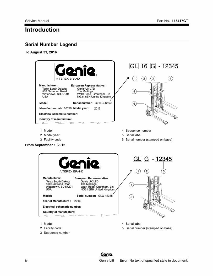
Serial Number Legend To August 31, 2016
1 Model 2 Model year 3 Facility code
4 Sequence number 5 Serial label 6 Serial number (stamped on base)
From September 1, 2016
1 Model 2 Facility code 3 Sequence number
4 Serial label 5 Serial number (stamped on base)

Part No. 115417GT Service Manual
Safety Rules
Error! No text of specified style in document. Genie Lift v
Section 1 Safety R ules
Danger Failure to obey the instructions and safety rules in this manual and the appropriate Operator's Manual on your machine will result in death or serious injury.
Many of the hazards identified in the operator's manual are also safety hazards when maintenance and repair procedures are performed.
Do Not Perform Maintenance Unless: You are trained and qualified to perform
maintenance on this machine.
You read, understand and obey:
• manufacturer's instructions and safety rules
• employer's safety rules and worksite regulations
• applicable governmental regulations
You have the appropriate tools, lifting equipment and a suitable workshop.

Service Manual Part No. 115417GT
Safety Rules
vi Genie Lift Error! No text of specified style in document.
Personal Safety Any person working on or around a machine must be aware of all known safety hazards. Personal safety and the continued safe operation of the machine should be your top priority.
Read each procedure thoroughly. This manual and the decals on the machine, use signal words to identify the following:
Safety alert symbol—used to alert personnel to potential personal injury hazards. Obey all safety messages that follow this symbol to avoid possible injury or death.
Indicates a imminently hazardous situation which, if not avoided, will result in death or serious injury.
Indicates a potentially hazardous situation which, if not avoided, could result in death or serious injury.
Indicates a potentially hazardous situation which, if not avoided, may cause minor or moderate injury.
Indicates a potentially hazardous situation which, if not avoided, may result in property damage.
Be sure to wear protective eye wear and other protective clothing if the situation warrants it.
Be aware of potential crushing hazards such as moving parts, free swinging or unsecured components when lifting or placing loads. Always wear approved steel-toed shoes.
Workplace Safety Any person working on or around a machine must be aware of all known safety hazards. Personal safety and the continued safe operation of the machine should be your top priority.
Be sure to keep sparks, flames and lighted tobacco away from flammable and combustible materials like battery gases and engine fuels. Always have an approved fire extinguisher within easy reach.
Be sure that all tools and working areas are properly maintained and ready for use. Keep work surfaces clean and free of debris that could get into machine components and cause damage.
Be sure any forklift, overhead crane or other lifting or supporting device is fully capable of supporting and stabilizing the weight to be lifted. Use only chains or straps that are in good condition and of ample capacity.
Be sure that fasteners intended for one time use (i.e., cotter pins and self-locking nuts) are not reused. These components may fail if they are used a second time.
Be sure to properly dispose of old oil or other fluids. Use an approved container. Please be environmentally safe.
Be sure that your workshop or work area is properly ventilated and well lit.

Part No. 115417GT
Table of Contents
Error! No text of specified style in document. Genie Lift vii
Introduction Introduction .......................................................................................................... ii Important Information ............................................................................................. ii
Find a Manual for this Model .................................................................................. ii
Revision History .....................................................................................................iii
Serial Number Legend .......................................................................................... iv
Section 1 Safety Rules .......................................................................................................... v General Safety Rules ............................................................................................. v
Section 2 Specifications ....................................................................................................... 9 Machine Specifications........................................................................................... 9
Performance Specifications ................................................................................. 11
SAE and Metric Fasteners Torque Charts ........................................................... 12
Section 3 Scheduled Maintenance Procedures ............................................................... 13 Introduction ........................................................................................................... 13
Pre-Delivery Preparation Report .......................................................................... 16
Maintenance Inspection Report ........................................................................... 18
Checklist A Procedures ..................................................................................... 20 A-1 Inspect the Manuals and Decals ................................................................... 20
A-2 Perform Pre-operation Inspection .................................................................. 21
A-3 Perform Function Tests ................................................................................. 21
A-4 Inspect the Channels ..................................................................................... 22
A-5 Inspect the Cable and Cable Pulleys............................................................. 22
A-6 Inspect the Casters and Wheels .................................................................... 23
Checklist B Procedures ..................................................................................... 24 B-1 Inspect the Battery - Models with Electric Winch .......................................... 24
B-2 Inspect the Electrical Wiring - Models With Electric Winch ........................... 25
B-3 Perform Electric WinchMaintenance ............................................................. 25
B-4 Inspect the Carriage Hold-down Bar ............................................................. 26
B-5 Inspect All Welds ........................................................................................... 26
B-6 Clean the Channels ...................................................................................... 27
B-7 Inspect and Lubricate the Manual Winch ...................................................... 27

Part No. 115417GT
Table of Contents
viii Genie Lift Error! No text of specified style in document.
Checklist C Procedures ..................................................................................... 28 C-1 Lubricate the Casters and Wheels ................................................................ 28
C-2 Replace the Manual Winch Friction Disks .................................................... 29
C-3 Inspect the Painted Surfaces ........................................................................ 29
Section 4 Repair Procedures ............................................................................................. 30
Base Assembly................................................................................................... 31 1-1 How to Disassemble the GL -Models Equipped with a Manual Winch.......... 31
1-2 How to Disassemble the GL - Models Equipped with an Electric Winch....... 32
1-3 How to Disassemble the Manual Winch ........................................................ 33
1-4 How to Assemble the Manual Winch ............................................................. 34
Manual Winch Assembly ...................................................................................... 36
1-5 How to Replace the Lifting Pulley .................................................................. 37
1-6 How to Replace the Lifting Cable .................................................................. 37
1-7 How to Replace the Glide Buttons ................................................................. 39
1-8 How to Adjust the Brake (if equipped) ........................................................... 40
Rear Wheel Brake Assembly (option) .................................................................. 41
Section 5 Schematics ......................................................................................................... 42 Electrical Symbols Legend - Models With Electric Winch.................................... 43
Wiring Diagram - Models With Electric Winch ..................................................... 44

Part No. 115417GT Service Manual
Specifications
Error! No text of specified style in document. Genie Lift 9
Section 2 Specificati ons
Machine Specifications Model GL-4 GL-8 Gl-10 GL-12 Stowed Height* 5 ft 7.5 in 5 ft 7.5 in 6 ft 6.5 in 7 ft 7 in 1.7 m 1.7 m 2 m 2.3 m
Ground Clearance* 0.75 in 0.75 in 0.75 in 0.75 in 1.9 cm 1.9 cm 1.9 cm 1.9 cm
Standard Base 24.75 in 24.75 in X X Width - stowed 63 cm 63 cm X X 34 in 34 in X X Length - stowed 86.4 cm 86.4 cm X X 59 in 63 in X X Length - operating 1.5 m 1.6 m X X
Straddle Base 28.75 in 28.75 in 28.75 in 28.75 in Width - stowed 73 cm 73 cm 73 cm 73 cm 43.5 in 43.5 in 43.5 in 43.5 in Width - extended 110.5 cm 110.5 cm 110.5 cm 110.5 cm
19.25 in 19.25 in 19.25 in 19.25 in Length - stowed 49 cm 49 cm 49 cm 49 cm 43 in 43 in 43 in 43 in Length - Operating 109.2 cm 109.2 cm 109.2 cm 109.2 cm
Counterweight Base 28.75 in 28.75 in 28.75 in X Width - stowed 73 cm 73 cm 73 cm X 43.5 in 43.5 in 43.5 in X Width - extended 110.5 cm 110.5 cm 110.5 cm X 28.5 in 28.5 in 28.5 in X Length - operating 72.4 cm 72.4 cm 72.4 cm X
* The 10 inch pneumatic rear wheel option will add 1 inch / 2.5 cm to these specifications. * The 4 point caster option B will add 1 inch / 2.5 cm to these specifications. * The counterweight base will add 1 inch / 2.5 cm to these specifications.

Service Manual Part No. 115417GT
Specifications
10 Genie Lift Error! No text of specified style in document.
Machine Specifications cont. Model GL-4 GL-8 Gl-10 GL-12 Machine Weight 113 lbs 132 lbs NA NA Standard base 51kg 60 kg
126 lbs 145 lbs 149 lbs 154 lbs Straddle base 57 kg 66 kg 68 kg 70 kg
392 lbs 411 lbs 433 lbs NA Counterweight base 178 kg 186 kg 196 kg Standard base 117 lbs 136 lbs NA NA (pneumatic caster option) 53 kg 60 kg
Straddle base 130 lbs 149 lbs 153 lbs 158 lbs (pneumatic caster option) 59 kg 68 kg 69 kg 72 kg
Straddle base 137 lbs 158 lbs 162 lbs 167 lbs (4 point caster option A) 62 kg 72 kg 74 kg 76 kg Straddle base 139 lbs 160 lbs 164 lbs 169 lbs (4 point caster option B) 63 kg 73 kg 75 kg 77 kg The electric winch option will add an additional 103 lbs / 47 kg to the above machine weights.
Forks 22.5 in 22.5 in 22.5 in 22.5 in Length 57.2 cm 57.2 cm 57.2 cm 57.2 cm 20.5 in 20.5 in 20.5 in 20.5 in Width 52.1 cm 52.1 cm 52.1 cm 52.1cm
Load Platform 23 in 23 in 23 in 23 in Length 58.4 cm 58.4 cm 58.4 cm 58.4 cm 22 in 22 in 22 in 22 in Width 55.9 cm 55.9 cm 55.9 cm 55.9 cm

Part No. 115417GT Service Manual
Specifications
Error! No text of specified style in document. Genie Lift 11
Performance Specifications Model GL-4 GL-8 GL-10 GL-12 Standard Forks
Maximum working height 5 ft 11 in 10 ft 0.5 in 11 ft 8 in 13 ft 9.5 in Forks up 1.8 m 3.1 m 3.6 m 4.2 m Maximum working height 4 ft 1.5 in 8 ft 3 in 9 ft 10.5 in 12 ft Forks down 1.3m 2.5 m 3 m 3.7 m Boom 5 ft 1.5 in 9 ft 3 in 10 ft 10.5 in 13 ft Maximum working height 1.6 m 2.8 m 3.3 m 4 m Load Platform 5 ft 1.5 in 9 ft 3 in 10 ft 10.5 in 13 ft Maximum working height 1.6 m 2.8 m 3.3 m 4 m
Standard Base 3.5 in 3.5 in 3.5 in 3.5 in Minimum working height 8.9 cm 8.9 cm 8.9 cm 8.9 cm
Straddle Base 3.5 in 3.5 in 3.5 in 3.5 in Minimum working height 8.9 cm 8.9 cm 8.9 cm 8.9 cm
Load Capacity
Standard Forks 500 lbs 400 lbs 350 lbs 350 lbs at 14 in / 36 cm load center 227 kg 182 kg 159 kg 159 kg Boom 500 lbs 400 lbs 350 lbs 350 lbs at 12 in / 30.5 cm load center 227 kg 182 kg 159 kg 159 kg Boom 300 lbs 240 lbs 210 lbs 210 lbs at 20 in / 51 cm load center 136 cm 109 kg 95 kg 95 kg
Airborne noise emissions by machinery
Manual winch 90 dB 90 dB 90 dB 90 dB Electric winch 95 dB 95 dB 90 dB 90 dB Maximum sound level at normal operating workstations (A-weighted)

Service Manual Part No. 115417GT
Specifications
12 Genie Lift Error! No text of specified style in document.

Part No. 115417GT Service Manual
Scheduled Maintenance Procedures
Error! No text of specified style in document. Genie Lift 13
Section 3 Schedul ed Mai ntenance Pr ocedures
Observe and Obey: Maintenance inspections shall be completed
by a person trained and qualified on the maintenance of this machine.
Scheduled maintenance inspections shall be completed daily, quarterly, and annually as specified on the Maintenance inspection Report. The frequency and extent of periodic examinations and tests may also depend on national regulations.
Failure to perform each procedure as presented and scheduled may cause death, serious injury or substantial damage.
Immediately tag and remove from service a damaged or malfunctioning machine.
Repair any machine damage or malfunction before operating the machine.
Use only Genie approved replacement parts.
Machines that have been out of service for a period longer than 3 months must complete the quarterly inspection.
Unless otherwise specified, perform each procedure with the machine in the following configuration:
• Machine parked on a firm, level surface
• Carriage fully lowered
• Casters locked
• Red Emergency Stop button pushed in to the off position (if equipped)
• Brakes locked (if equipped)
About This Section This section contains detailed procedures for each scheduled maintenance inspection.
Each procedure includes a description, safety warnings and step-by-step instructions.
Symbols Legend
Safety alert symbol—used to alert personnel to potential personal injury hazards. Obey all safety messages that follow this symbol to avoid possible injury or death.
Indicates a imminently hazardous situation which, if not avoided, will result in death or serious injury.
Indicates a potentially hazardous situation which, if not avoided, could result in death or serious injury.
Indicates a potentially hazardous situation which, if not avoided, may cause minor or moderate injury.
Indicates a potentially hazardous situation which, if not avoided, may result in property damage.
Indicates that a specific result is expected after performing a series of steps.
Indicates that an incorrect result has occurred after performing a series of steps.

Service Manual Part No. 115417GT
Scheduled Maintenance Procedures
14 Genie Lift Error! No text of specified style in document.
Maintenance Symbols Legend Note: The following symbols have been used in this manual to help communicate the intent of the instructions. When one or more of the symbols appear at the beginning of a maintenance procedure, it conveys the meaning below.
Indicates that tools will be required to perform this procedure.
Indicates that new parts will be required to perform this procedure.
Indicates that dealer service will be required to perform this procedure.
Pre-delivery Preparation Report The pre-delivery preparation report contains checklists for each type of scheduled inspection.
Make copies for each inspection. Store completed forms as required.
Maintenance Schedule The Scheduled Maintenance Procedures section and the Maintenance Inspection Report have been divided into subsections. Use the following chart to determine which group(s) of procedures are required to perform a scheduled inspection.
Inspection Checklist Daily or every 8 hours A Quarterly or every 250 hours A + B Annually or every 1000 hours A + B + C
Maintenance Inspection Report The maintenance inspection report contains checklists for each type of scheduled inspection.
Make copies of the Maintenance Inspection Report to use for each inspection. Maintain completed forms for a minimum of 4 years or in compliance with your employer, jobsite and governmental regulations and requirements.

Part No. 115417GT Service Manual
Error! No text of specified style in document. Genie Lift 15
This page intentionally left blank.

Service Manual Part No. 115417GT
Pre-Delivery Preparation Report
Fundamentals It is the responsibility of the owner or dealer to perform the Pre-delivery Preparation.
The Pre-delivery Preparation is performed prior to each delivery. The inspection is designed to discover if anything is apparently wrong with a machine before it is put into service.
A damaged or modified machine must never be used. If damage or any variation from factory delivered condition is discovered, the machine must be tagged and removed from service.
Repairs to the machine may only be made by a qualified service technician, according to the manufacturer's specifications.
Scheduled maintenance inspections shall be performed by qualified service technicians, according to the manufacturer's specifications and the requirements listed in the responsibilities manual.
Instructions Use the operator’s manual on your machine.
The Pre-delivery Preparation consists of completing the Pre-operation Inspection, the Maintenance items and the Function Tests.
Use this form to record the results. Place a check in the appropriate box after each part is completed. Follow the instructions in the operator’s manual.
If any inspection receives an N, remove the machine from service, repair and re-inspect it. After repair, place a check in the R box.
Legend Y = yes, acceptable N = no, remove from service R = repaired
Comments Pre-delivery Preparation Y N R
Pre-operation inspection completed
Maintenance items completed
Function tests completed
Model
Serial number Date Machine owner Inspected by (print) Inspector signature Inspector title Inspector company

Part No. 115417GT Service Manual
Error! No text of specified style in document. Genie Lift 17
This page intentionally left blank.

Service Manual Part No. 115417GT
Maintenance Inspection Report
18 Genie Lift Error! No text of specified style in document.
Model
Serial number
Date
Hour meter
Machine owner
Inspected by (print)
Inspector signature
Inspector title
Inspector company
Instructions • Make copies of this report to use for
each inspection. • Select the appropriate checklist(s) for
the type of inspection(s) to perform.
Daily or every 8 hours A Quarterly or every
250 hours A + B
Annually or every 1000 hours
A + B + C
• Place a check in the appropriate box after each inspection procedure is completed.
• Use the step-by-step procedures in this section to learn how to perform these inspections.
• If any inspection receives an "N," tag and remove the machine from service, repair and re-inspect it. After repair, place a check in the "R" box.
Legend
Y = yes, acceptable N = no, remove from service R = repaired
Checklist A Y N R
A-1 Inspect the manuals and decals
A-2 Pre-operation inspection
A-3 Function tests
A-4 Inspect the channels
A-5 Inspect cable and pulleys
A-6 Inspect casters and wheels
Checklist B Y N R
B-1 Battery
B-2 Electrical wiring
B-3 Electric winch maintenance
B-4 Carriage hold-down
B-5 Inspect welds
B-6 Clean channels
B-7 Inspect and lubricate manual winch
Checklist C Y N R
C-1 Caster and wheels
C-2 Winch friction disks
C-3 Inspect painted surfaces
Comments

Part No. 115417GT Service Manual
Error! No text of specified style in document. Genie Lift 19
This page intentionally left blank.

Service Manual Part No. 115417GT
Checklist A Procedures
20 Genie Lift Error! No text of specified style in document.
A-1 Inspect the Manuals and Decals Genie specifications require that this procedure be performed every 8 hours or daily, whichever comes first.
Maintaining the operator’s and safety manuals in good condition is essential to safe machine operation. Manuals are included with each machine and should be stored in the container provided in the platform. An illegible or missing manual will not provide safety and operational information necessary for a safe operating condition.
In addition, maintaining all of the safety and instructional decals in good condition is mandatory for safe machine operation. Decals alert operators and personnel to the many possible hazards associated with using this machine. They also provide users with operation and maintenance information. An illegible decal will fail to alert personnel of a procedure or hazard and could result in unsafe operating conditions.
1 Check to make sure that the operator's, safety and responsibilities manuals are present and complete in the storage container on the platform.
2 Examine the pages of each manual to be sure that they are legible and in good condition.
Result: The operator's manual is appropriate for the machine and all manuals are legible and in good condition.
Result: The operator's manual is not appropriate for the machine or all manuals are not in good condition or is illegible. Remove the machine from service until the manual is replaced.
3 Open the operator's manual to the decals inspection section. Carefully and thoroughly inspect all decals on the machine for legibility and damage.
Result: The machine is equipped with all required decals, and all decals are legible and in good condition.
Result: The machine is not equipped with all required decals, or one or more decals are illegible or in poor condition. Remove the machine from service until the decals are replaced.
4 Always return the manuals to the storage container after use.
Note: Contact your authorized Genie distributor or Genie if replacement manuals or decals are needed.
Part No. 115417GT Service Manual
Checklist A Procedures
Error! No text of specified style in document. Genie Lift 21
A-2 Perform Pre-operation Inspection Genie specifications require that this procedure be performed every 8 hours or daily, whichever comes first.
Completing a Pre-operation Inspection is essential to safe machine operation. The Pre-operation Inspection is a visual inspection performed by the operator prior to each work shift. The inspection is designed to discover if anything is apparently wrong with a machine before the operator performs the function tests. The Pre-operation Inspection also serves to determine if routine maintenance procedures are required.
Complete information to perform this procedure is available in the appropriate operator's manual. Refer to the Operator's Manual on your machine.
A-3 Perform Function Tests Genie specifications require that this procedure be performed every 8 hours or daily, whichever comes first.
Completing the function tests is essential to safe machine operation. Function tests are designed to discover any malfunctions before the machine is put into service. A malfunctioning machine must never be used. If malfunctions are discovered, the machine must be tagged and removed from service.
Complete information to perform this procedure is available in the appropriate operator's manual. Refer to the Operator's Manual on your machine.

Service Manual Part No. 115417GT
Checklist A Procedures
22 Genie Lift Error! No text of specified style in document.
A-4 Inspect the Channels Genie specifications require that this procedure be performed every 8 hours or daily, whichever comes first.
Detection of damage to the inner and outer frame channels is essential for safe machine operation. An unsafe working condition exists if the channels are damaged and do not operate smoothly, free of hesitation and binding. A daily check of the channels allows the inspector to identify changes in the operating condition of the unit that might indicate damage.
1 Visually inspect each channel for the following:
• Dents, gauges or abrasions
• Bends or warping
• Excessive wear
2 Raise and lower the carriage through a complete cycle.
Result: The carriage and inner frame (if equipped) should raise and lower smoothly, free of hesitation and binding.
A-5 Inspect the Cable and Cable Pulleys Genie specifications require that this procedure be performed every 8 hours or daily, whichever comes first.
Detection of damage to the cable or pulleys is essential for safe machine operation. An unsafe working condition exists if these components are damaged and do not operate smoothly. A daily check of this system allows the inspector to identify changes in the operating condition that might indicate damage.
1 Visually inspect all cable components for the following:
• Frayed or broken wire strands
• Kinks in the cable
• Corrosion
• Paint or foreign materials
• Split or cracked swaged end
• Cable is properly secured to the winch
• Cable is properly secured to the upper inner frame casting (GL8, GL10 and GL12)
• Cable is properly secured to the cable anchor (GL4)
• Cable is on all pulleys
• No broken or damaged pulleys
• No unusual or excessive pulley wear

Part No. 115417GT Service Manual
Checklist A Procedures
Error! No text of specified style in document. Genie Lift 23
A-6 Inspect the Casters and Wheels
Genie specifications require that this procedure be performed every 8 hours or daily, whichever comes first.
Maintaining the casters and wheels in good condition is essential to safe operation and good performance. Casters or wheel failure could result in a machine tip-over. Component damage may also result if problems are not discovered and repaired in a timely fashion. Extremely dirty conditions may require that the wheels and casters be inspected more often.
1 Unlock the brake (if equipped) and move the machine on a firm smooth surface and check that the casters and wheels roll smoothly, free of hesitation and binding.
2 Models with Pneumatic Wheel: Check the tire pressure with an air pressure gauge and add air as needed.
Specification
Pneumatic tires 50 psi 3.4 bar
Service Manual Part No. 115417GT
Checklist B Procedures
24 Genie Lift Error! No text of specified style in document.
B-1 Inspect the Battery -Models with Electric Winch
Genie specifications require that this procedure be performed every 250 hours or quarterly, whichever comes first.
Proper battery condition is essential to good machine performance and operational safety. Improper fluid levels or damaged cables and connections can result in component damage and hazardous conditions.
Electrocution/burn hazard. Contact with electrically charged circuits could result in death or serious injury. Remove all rings, watches and other jewelry.
Bodily injury hazard. Batteries contain acid. Avoid spilling or contacting battery acid. Neutralize battery acid spills with baking soda and water.
1 Put on protective clothing and eye wear.
2 Be sure that the battery cable connections are free of corrosion.
Note: Adding terminal protectors and a corrosion preventative sealant will help eliminate corrosion on the battery terminals and cables.
3 Be sure that the battery retainers and cable connections are tight.
4 Fully charge the battery. Allow the battery to rest 24 hours before performing this procedure to allow the battery cells to equalize.
5 Remove the battery vent caps and check the specific gravity of each battery cell with a hydrometer. Note the results.
6 Check the ambient air temperature and adjust the specific gravity reading for each cell as follows:
• Add 0.004 to the reading of each cell for every 10° / 5.5° C above 80° F / 26.7° C.
• Subtract 0.004 from the reading of each cell for every 10° / 5.5° C below 80° F / 26.7° C.
Result: All battery cells display an adjusted specific gravity of 1.277 or higher. The battery is fully charged. Proceed to step 12.
Result: One or more battery cells display a specific gravity of 1.217 or below. Proceed to step 9.
7 Perform an equalizing charge OR fully charge the batteries and allow the battery to rest at least 6 hours.
8 Remove the battery vent caps and check the specific gravity of each battery cell with a hydrometer. Note the results.
9 Check the ambient air temperature and adjust the specific gravity reading for each cell as follows:
• Add 0.004 to the reading of each cell for every 10° / 5.5° C above 80° F / 26.7° C.
• Subtract 0.004 from the reading of each cell for every 10° / 5.5° C below 80° F / 26.7° C.
Result: All battery cells display a specific gravity of 1.277 or greater. The battery is fully charged. Proceed to step 10.
Result: The difference in specific gravity readings between cells is greater than 0.1 OR the specific gravity of one or more cells is less than 1.217. Replace the battery.
10 Check the battery acid level. If needed, replenish with distilled water to 1/8 inch / 3 mm below the bottom of the battery fill tube. Do not overfill.
11 Install the vent caps and neutralize any electrolyte that may have spilled.

Part No. 115417GT Service Manual
Checklist B Procedures
Error! No text of specified style in document. Genie Lift 25
B-2 Inspect the Electrical Wiring - Models with Electric Winch
Genie requires that this procedure be performed every 250 hours or quarterly, whichever comes first.
Maintaining electrical wiring in good condition is essential to safe operation and good machine performance. Failure to find and replace burnt, chafed, corroded or pinched wires could result in unsafe operating conditions and may cause component damage.
Electrocution/burn hazard. Contact with electrically charged circuits could result in death or serious injury. Remove all rings, watches and other jewelry.
1 Inspect the following areas for burnt, chafed, pinched, corroded and loose wires:
• Control panel
• Battery pack
• Remote control
• Channel frame
B-3 Perform Electric Winch Maintenance Genie specifications require that this procedure be performed every 250 hours or quarterly, whichever comes first.
Required maintenance procedures and additional winch information is available in the Owner Manual for Rule Winches (Rule part number W-1013).
Owner Manual for Rule Winches Genie part number 85220
Service Manual Part No. 115417GT
Checklist B Procedures
26 Genie Lift Error! No text of specified style in document.
B-4 Inspect the Carriage Hold-down Bar Genie specifications require that this procedure be performed every 250 hours or quarterly, whichever comes first.
Detection of damage to the carriage hold-down bar assembly is essential to safe machine operation. An unsafe working condition exists if the system is damaged and does not operate properly.
1 Fully lower the carriage.
2 Rotate the carriage hold-down bar over the carriage.
3 Raise the carriage
Result: The carriage should not move.
Component Damage Hazard. Do not apply too much force on the carriage. Raise it only enough to check the resistance against the hold-down bar.
4 Visually inspect the assembly for damage.
B-5 Inspect All Welds Genie specifications require that this procedure be performed every 250 hours or quarterly, whichever comes first.
Weld inspections are essential to safe machine operation and good machine performance. Failure to locate and repair damage may result in an unsafe operating condition.
1 Visually inspect the welds in the following locations:
• Base and base components
• Legs
• Carriage
• Forks
• Boom (if equipped)

Part No. 115417GT Service Manual
Checklist B Procedures
Error! No text of specified style in document. Genie Lift 27
B-6 Clean the Channels
Genie specifications require that this procedure be performed every 250 hours or quarterly, whichever comes first.
Clean inner (if equipped) and outer frame channels are essential to good machine performance and safe operation. Extremely dirty conditions may require that the channels be cleaned more often.
1 Raise the carriage to the maximum height.
2 Visually inspect the inner (if equipped) and outer frame channels for debris or foreign material. If necessary, use a mild cleaning solvent to clean the channels.
3 If needed, lubricate the inner (if equipped) and outer channels with a dry silicone spray or silicone wax
B-7 Inspect and Lubricate the Manual Winch
Genie specifications require that this procedure be performed every 250 hours or quarterly, whichever comes first.
Maintaining the winch is essential to good machine performance and safe operation. An unsafe working condition exists if the winch has excessive wear and/or does not operate smoothly, free of hesitation and binding.
1 Carefully lubricate the pivot point on the ratchet pawl with 30W oil.
Bodily Injury Hazard. Over-lubrication of the ratchet pawl may result in oil coming in contact with the surface of the winch brake disk or the winch pressure plate, leading to an unsafe working condition. Do not allow any oil on the brake or pressure plate.
2 Inspect the brake disks for excessive wear. Replace if pad is less than 1/16 inch /1.5 mm thick.
3 Inspect the pinion shaft bushings for excessive wear. Replace if wall thickness of bushing is less than specified.
Bushing Specification Small bushing 0.172 inch 4.34 mm Large bushing 0.109 inch 2.76 mm

Service Manual Part No. 115417GT
Checklist C Procedures
28 Genie Lift Error! No text of specified style in document.
C-1 Lubricate the Casters and Wheels
Genie specifications require that this procedure be performed every 1000 hours or annually, whichever comes first.
Regular application of lubrication to the Caster or Wheel is essential to good machine performance and service life. Extremely dirty conditions may require that the casters and wheels be inspected and lubricated more often.
1 Visually inspect each caster and wheel for cuts, cracks or unusual wear.
2 Move the machine on a flat, smooth surface to confirm the casters and wheels roll smoothly, free of hesitation and binding.
3 Pump grease into the caster or wheel until it can be seen coming out of the bearing gap.
Grease Specification
Chevron Ultra-duty grease, EP NLGI 1 (lithium based) or equivalent

Part No. 115417GT Service Manual
Checklist C Procedures
Error! No text of specified style in document. Genie Lift 29
C-2 Inspect the Safety Brake System (if equipped)
Genie specifications require that this procedure be performed every 1000 hours or annually, whichever comes first.
Maintaining the winch is essential to good machine performance and safe operation. An unsafe working condition exists if the winch has excessive wear and/or does not operate smoothly, free of hesitation and binding.
1 Replace the winch brake disks and lubricate the winch shaft. Refer to Repair Procedure, How to Disassemble the Manual Winch.
C-3 Inspect the Painted Surfaces Genie specifications require that this procedure be performed every 1000 hours or annually, whichever comes first.
Inspecting the painted surfaces of your machine is essential to safe operation and long machine life. An unsafe working condition exists if there is damage to painted surfaces that is not corrected.
1 Visually inspect all painted surfaces for the following conditions:
• Blistering
• Rust
• Peeling
• Fading
• Corrosion
Note: Replace any component that is damaged.
Service Manual Part No. 115417GT
Repair Procedures
30 Genie Lift Error! No text of specified style in document.
Section 4 Repair Pr ocedures
Observe and Obey: Repair procedures shall be completed by a
person trained and qualified on the repair of this machine.
Immediately tag and remove from service a damaged or malfunctioning machine.
Repair any machine damage or malfunction before operating the machine.
Before Repairs Start: Read, understand and obey the safety rules
and operating instructions in the appropriate operator's manual on your machine.
Be sure that all necessary tools and parts are available and ready for use.
Use only Genie approved replacement parts.
Read each procedure completely and adhere to the instructions. Attempting shortcuts may produce hazardous conditions.
Machine Configuration: Unless otherwise specified, perform each
repair procedure with the machine in the following configuration:
• Machine parked on a firm, level surface
• Carriage in the stowed position
• Casters locked
• Red Emergency Stop button in the off position (if equipped)
• Brake locked (if equipped)
• All external AC power supply disconnected from the machine (models with electric winch)
About This Section Most of the procedures in this section should only be performed by trained service professional in a suitably equipped workshop. Select the appropriate repair procedure after troubleshooting the problem.
Perform disassembly procedures to the point where repairs can be completed. Then to re-assemble, perform the disassembly steps in reverse order.
Symbols Legend
Safety alert symbol—used to alert personnel to potential personal injury hazards. Obey all safety messages that follow this symbol to avoid possible injury or death.
Indicates a imminently hazardous situation which, if not avoided, will result in death or serious injury.
Indicates a potentially hazardous situation which, if not avoided, could result in death or serious injury.
Indicates a potentially hazardous situation which, if not avoided, may cause minor or moderate injury.
Indicates a potentially hazardous situation which, if not avoided, may result in property damage.
Indicates that a specific result is expected after performing a series of steps.
Indicates that an incorrect result has occurred after performing a series of steps.

Part No. 115417GT Service Manual
Base Assembly
Error! No text of specified style in document. Genie Lift 31
1-1 How to Disassemble the GL -Models Equipped with a Manual Winch 1 Remove the load handling attachment from
the carriage.
2 Fully lower the carriage.
Models with counterweight base:
3 Support the base counterweights with a proper lifting device.
4 Remove the counterweight retaining fasteners from the base and remove the counterweight from the base.
All models:
5 Using proper lifting techniques, lay the machine over onto a table or other suitable work surface.
6 Remove the legs from the machine.
7 Remove the jam nut from the winch drum bolt and remove the winch drum cover.
8 Remove the cable retaining fastener from the winch drum and remove the cable from the drum.
Bodily injury hazard. Cables can fray. Always wear adequate hand protection when handling cable.
9 GL-4 models: Remove the cable mounting fastener from the handle bracket. GL-8, GL-10 and GL-12 models: Remove the cable mounting fastener from the upper inner frame casting.
Bodily injury hazard. Cables can fray. Always wear adequate hand protection when handling cable.
10 Remove the base mounting fasteners from the outer frame channels and remove the base from the machine.
11 GL-4 models: Remove the carriage from the outer frame. GL-8, GL-10 and GL-12: Remove the inner frames from the outer frame. Remove the carriage from the outer frame. Proceed to step 14.
Note: After removing the carriage, note the location of the roller wheel buttons, on the carriage roller wheels.
12 Remove the mounting fasteners from the lower inner frame casting and remove the lower casting from the inner frame.
13 Remove the carriage from the inner frame.
Note: After removing the carriage, note the location of the roller wheel buttons, on the carriage roller wheels.
14 If necessary, remove the hold-down bar, winch mounting plate, handle and loading wheel bracket.
Note: When installing the cable, be sure the cable thimble is centered below the upper pulley (GL-8, GL-10 and GL-12 models).
Note: For proper cable routing, see Repair Procedure, How to Replace the Lifting Cable.

Service Manual Part No. 115417GT
Base Assembly
32 Genie Lift Error! No text of specified style in document.
1-2 How to Disassemble the Winch 1 Remove the load handling attachment from
the carriage.
2 Fully lower the carriage
3 Disconnect the battery from the machine.
Electrocution/burn hazard. Contact with electrically charged circuits could result in death or serious injury. Remove all rings, watches and other jewelry.
4 Remove the battery and battery charger from the machine.
Models with counterweight base:
5 Support the base counterweights with a proper lifting device.
6 Remove the counterweight retaining fasteners from the base and remove the counterweight from the base.
All models:
7 Using proper lifting techniques, lay the machine over onto a table or other suitable work surface.
8 Remove the legs from the machine.
9 GL-4 models: Remove the cable mounting fastener from the handle bracket. GL-8, GL-10 and GL-12 models: Remove the cable mounting fastener from the upper inner frame casting.
10 Remove the mounting fasteners from the electric winch cover.
11 Tag and disconnect the wiring from the electric winch cover and remove the electric winch cover from the machine.
12 Remove the old cable following instructions in the Owner's Manual for Rule Winches (Rule part number W-1013).
Owner Manual for Rule Winches Genie part number 85220
Bodily injury hazard. Cables can fray. Always wear adequate hand protection when handling cable.
Remove the base mounting fasteners from the outer frame channels and remove the base from the machine.
13 Remove the limit switch mounting fasteners and remove the limit switch from the machine.
14 GL-4 models: Remove the carriage from the outer frame. Proceed to step 21.
Note: After removing the carriage, note the location of the roller wheel buttons, on the carriage roller wheels.

Part No. 115417GT Service Manual
Base Assembly
Error! No text of specified style in document. Genie Lift 33
15 GL-8, GL-10 and GL-12 models: Remove the mounting fasteners from the lower inner frame casting and remove the lower casting from the inner frame.
16 Remove the carriage from the inner frame.
17 Remove the mounting fasteners from the lower inner frame casting and remove the lower casting from the inner frame.
18 Tag and disconnect the wiring from the electric winch.
19 Remove the electric winch mounting fasteners and remove the electric winch from the machine.
20 Remove the carriage from the inner frame.
Note: After removing the carriage, note the location of the roller wheel buttons, on the carriage roller wheels.
21 If necessary, remove the hold-down bar, winch mounting plate, limit switch mounting bracket, handle and loading wheel bracket.
Note: For proper cable routing, refer to Repair Procedure, How to Replace the Lifting Cable.
1-3 How to Disassemble the Manual Winch Note: Refer to the illustration, Winch Assembly, for an exploded view.
1 Fully lower the carriage
2 Remove the jam nut from the winch drum bolt. Remove the winch drum cover from the machine.
3 Remove the cable retaining fastener from the winch drum and remove the cable from the drum.
Bodily injury hazard. Cables can fray. Always wear adequate hand protection when handling cable.
4 Remove the handle adaptor nut and spring. Remove the handle adaptor from the machine.
5 Remove the handle from the pinion shaft.
6 Remove the drum bolt and remove the drum from winch.
7 Remove the retaining ring from the pinion shaft.
8 Slide the pinion shaft toward the carriage and remove the pressure plate, ratchet gear and brake face.
9 Remove the pinion shaft from the winch housing.
10 Remove both pinion bushings. Use a soft metal drift equal to the outside diameter of each bushing and tap with rubber mallet.
Component damage hazard. Place a block between the walls of the winch housing to prevent the housing from bending while removing the bushings.
11 If necessary, remove the winch housing from the machine.
Service Manual Part No. 115417GT
Base Assembly
34 Genie Lift Error! No text of specified style in document.
1-4 How to Assemble the Manual Winch
Bodily injury hazard. Cables can fray. Always wear adequate hand protection when handling cable.
Note: Refer to the illustration, Winch Assembly, for an exploded view.
1 Place one side of the winch housing over a vise. Open the vise until it is wider than the outside diameter of the pinion shaft bushing.
2 Insert a soft metal drift through the opposite bushing hole. Tap the drift with a rubber mallet to push the bushing into place.
Note: Use a piece of flat bar in between the drift and the bushing to prevent any damage to the bushing.
Note: Repeat steps 1 and 2 to insert the other bushing.
3 Carefully lubricate the pivot point on the ratchet pawl with 30W oil.
Bodily Injury Hazard. Over-lubrication of the ratchet pawl may result in oil coming in contact with the surface of the winch brake disk or the winch pressure plate, leading to an unsafe working condition. Do not allow any oil on the brake or pressure plate.
4 Install the winch housing onto the machine. Be sure the winch drum is towards the right.
5 Insert the threaded end of the pinion shaft through the large bushing. Then insert the other end of the pinion shaft through the small bushing.
6 Push the pinion shaft toward the small bushing. Install the brake disk, ratchet gear and pressure plate.
Note: The teeth on the ratchet gear must curve away from the drum.
7 Push the pinion shaft toward the large bushing. Install the pinion shaft retaining ring.
Note: Push the ratchet pawl outwards while pushing the pinion shaft through the large bushing. Be sure the ratchet pawl is in firm contact with the ratchet gear and all parts move freely.
8 Install the handle adaptor, spring and handle adaptor mounting nut. Tighten the mounting nut. Do not over-tighten the nut.
9 Lubricate the outside of the drum spacer that goes through the cable drum with automotive grease. Insert the drum spacer into the cable drum.
10 Install the cable drum so that the drum gears mesh with the ratchet gears on the pinion shaft.
11 Install the drum bolt through the winch housing and drum with the head of the drum bolt on the small bushing side of winch.
Part No. 115417GT Service Manual
Base Assembly
Error! No text of specified style in document. Genie Lift 35
12 From the winch side of the machine, wrap the cable 1 time counterclockwise around the winch drum. Thread the cable through the oblong hole and attach it to the winch drum with the cable retaining fastener.
13 While holding the cable tie on the drum, rotate the winch until all the cable is spooled onto the drum neatly and evenly. Be sure there are at least 4 wraps of cable on the winch drum.
Component damage hazard. Improperly wound cable may result in poor winch performance and accelerate cable wear. Be sure the cable winds onto the winch drum evenly.

Service Manual Part No. 115417GT
Base Assembly
36 Genie Lift Error! No text of specified style in document.
Manual Winch Assembly - ANSI Index No. Description
Index No. Description
1 Ratchet Pawl Kit 13 Lock Pin 2 Cable Drum 14 Handle Adapter Nut 3 Carriage Bolt 15 Winch Handle Spring 4 Hex Nut 16 Handle Adapter 5 Gear Cover 17 Pinion Shaft Bushing 6 Cable Keeper 18 Pressure Plate 7 Nylock Nut 19 Ratchet Gear 8 Screw 20 Disk Brake 9 Lock Nut 21 Drive Shaft Assembly 10 Winch Frame 22 Retaining Ring 11 Winch Handle Assembly 23 Pinion Shaft Bushing 12 Flat Washer

Part No. 115417GT Service Manual
Base Assembly
Error! No text of specified style in document. Genie Lift 37
1-5 How to Replace the Lifting Pulley 1 Fully lower the carriage.
2 Unwind the cable from the winch drum. Do not remove the cable.
Bodily injury hazard. Cables can fray. Always wear adequate hand protection when handling cable.
3 Remove the pulley mounting fastener and remove the pulley from the machine.
4 Wrap the cable around the new pulley and install the pulley on to the machine.
Note: Be sure not to twist the cable when installing the new pulley.
1-6 How to Replace the Lifting Cable Models with manual winch:
1 Fully lower the carriage.
2 Remove the jam nut from the winch drum bolt and remove the winch drum cover.
3 Remove the cable retaining fastener from the winch drum and unwind the cable from the winch drum.
The numbers on the illustration correspond to the steps in Repair Procedure, How to Replace the Lifting Cable.
Service Manual Part No. 115417GT
Base Assembly
38 Genie Lift Error! No text of specified style in document.
4 GL-4 models: Remove the cable mounting fastener from the handle bracket. Pull all the cable out of the machine. GL-8, GL-10 and GL-12 models: Remove the cable mounting fastener from the upper inner frame casting. Pull all the cable out of the machine.
5 GL-4 models: Attach the new cable to the handle bracket.
Note: When installing the cable, be sure the cable thimble (swaged end) is centered below the upper pulley.
Facing the carriage side of the machine:
6 Thread the cable through the cable slot and then through the carriage pulley, from front to back. Pull all the cable through the pulley.
GL-8, GL-10 and GL-12 models:
7 Thread the cable through the upper inner frame pulley, from back to front. Pull all the cable through the pulley.
8 From front to back, thread the cable through the cable slot in front of the carriage pulley through the lower inner frame pulley. Pull all the cable through the pulley.
All models:
9 From front to back, thread the cable through the handle weldment pulley. Pull all the cable through the pulley.
10 From the winch side of the machine, wrap the cable 1 time counterclockwise around the winch drum. Thread the cable through the oblong hole and attach it to the winch drum with the cable retaining fastener.
11 While holding the cable tie on the drum, rotate the winch until all the cable is spooled onto the drum. Be sure there are at least 4 wraps of cable on the winch drum.

Part No. 115417GT Service Manual
Base Assembly
Error! No text of specified style in document. Genie Lift 39
Models with electric winch:
1 Remove the load handling attachment from the carriage.
2 Fully lower the carriage.
3 Push in the red Emergency Stop button to the off position.
4 Disconnect the battery from the machine.
Electrocution/burn hazard. Contact with electrically charged circuits could result in death or serious injury. Remove all rings, watches and other jewelry.
5 Remove the battery and battery charger from the machine.
6 Remove the winch cover fasteners.
7 Tag and disconnect the winch wiring and remove the winch cover.
8 Remove the old cable following instructions in the Owner's Manual for Rule Winches (Rule part number W-1013).
Owner Manual for Rule Winches
Genie part number 85220
Bodily injury hazard. Cables can fray. Always wear adequate hand protection when handling cable.
Install the new cable following the instructions in the Owner's Manual for Rule Winches.
9 Connect the winch wiring and install the winch cover on to the machine.
1-7 How to Replace the Glide Buttons 1 Remove the load handling attachment from
the carriage.
2 Fully lower the carriage.
Models with counterweight base:
3 Support the base counterweights with a proper lifting device.
4 Remove the counterweight retaining fasteners from the base and remove the counterweight from the base.
Models with electric winch:
5 Push in the red Emergency Stop button to the off position.
6 Disconnect the battery from the machine.
Electrocution/burn hazard. Contact with electrically charged circuits could result in death or serious injury. Remove all rings, watches and other jewelry.
7 Remove the battery and battery charger from the machine.
All models:
8 Using proper lifting techniques, lay the machine over onto a table or other suitable work surface.

Service Manual Part No. 115417GT
Base Assembly
40 Genie Lift Error! No text of specified style in document.
9 Remove the legs from the base.
10 Remove the base mounting fasteners from the outer frame channels. Then remove the base from the machine.
11 GL-8, GL-10, GL-12: Slide the inner frame out the bottom of the outer frame approximately6 inches / 15 cm.
12 Use a soft metal drift to remove the glide button.
13 Press the new glide button in place until it is fully seated.
1-8 How to Adjust the Brake (if equipped) Note: Refer to the illustration, Rear Wheel Brake Assembly (option), for an exploded view.
1 Rotate the brake pedal to the up or unlocked position.
2 Loosen the clamping bolts from all three of the brake cams.
3 Rotate both of the wheel-brake cams until they contact the tires. Tighten the brake cam clamping bolts.
4 With the pedal up, rotate the brake cam rod until there is approximately 1/4 inch of gap between the wheel and the wheel-brake cam. Tighten the center brake cam clamping bolt.
5 Check the brake for proper activation.
Note: Apply enough force to the brake pedal to lock the brakes in place. After the brakes are engaged, the brakes should hold the wheels in place with enough force to keep the wheels from turning.
Part No. 115417GT Service Manual
Base Assembly
Error! No text of specified style in document. Genie Lift 41
Rear Wheel Brake Assembly (option) Index No. Description
Index No. Description
1 Screw 14 Brake Linkage Spring 2 Lock Washer 15 Axle Tube 3 Nut 16 Spring Retaining Washer 4 Stair Roller Mount Bracket, Right Side 17 Screw 5 Stair Roller Spacer 18 Flat Washer 6 Stair Roller 19 Solid Rubber Wheel 7 Brake Cam Rod 20 Screw 8 Stair Roller Mount Bracket, Left Side 21 Base 9 Brake Cam Spacer 22 Brake Pedal 10 Screw 23 Screw 11 Nylock Nut 24 Nylock Nut 12 Brake Cam 25 Brake Linkage Plate 13 Brake Pivot Plate

Service Manual Part No. 115417GT
Schematics
42 Genie Lift Error! No text of specified style in document.
Section 5 Schem atics
Observe and Obey: Troubleshooting and repair procedures shall
be completed by a person trained and qualified on the repair of this machine
Immediately tag and remove from service a damaged or malfunctioning machine.
Repair any machine damage or malfunction before operating the machine.
Before Troubleshooting: Read, understand and obey the safety rules
and operating instructions in the appropriate operator's manual on your machine.
Be sure that all necessary tools and test equipment are available and ready for use.
About This Section An illustration legend precedes the electrical schematics.
Electrical Schematics
Electrocution/burn hazard. Contact with electrically charged circuits could result in death or serious injury. Remove all rings, watches and other jewelry.
General Repair Process

Part No. 115417GT Service Manual
Electrical Symbols Legend - Models with Electric Winch
Error! No text of specified style in document. Genie Lift 43
Service Manual Part No. 115417GT
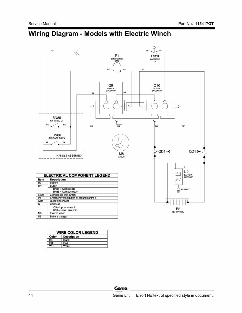
Wiring Diagram - Models with Electric Winch
44 Genie Lift Error! No text of specified style in document.
Genie Lif t Part No. 115417GT Service M anual Decem ber 2017