Embed Size (px)
Citation preview
6B
CLOSED COOLED MODELSSERVICE MANUAL NUMBER 24
90-861327--1 OCTOBER 1999 Page 6B-1
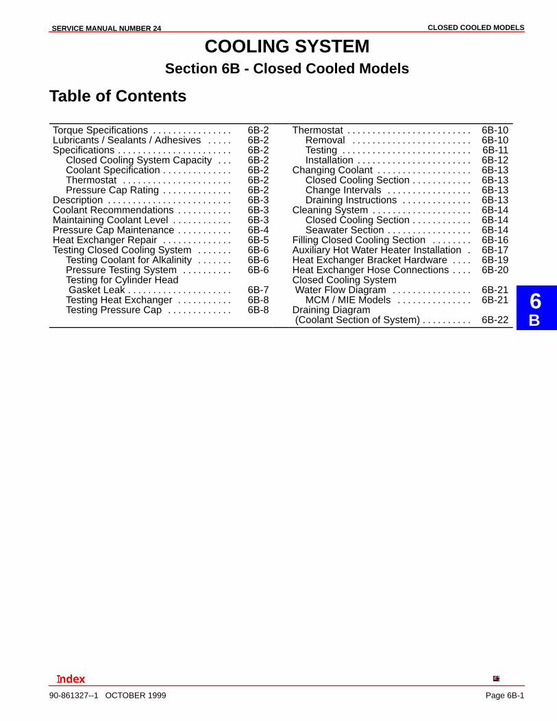
COOLING SYSTEMSection 6B - Closed Cooled Models
Table of Contents
Torque Specifications 6B-2. . . . . . . . . . . . . . . . Lubricants / Sealants / Adhesives 6B-2. . . . . Specifications 6B-2. . . . . . . . . . . . . . . . . . . . . . .
Closed Cooling System Capacity 6B-2. . . Coolant Specification 6B-2. . . . . . . . . . . . . . Thermostat 6B-2. . . . . . . . . . . . . . . . . . . . . . Pressure Cap Rating 6B-2. . . . . . . . . . . . . .
Description 6B-3. . . . . . . . . . . . . . . . . . . . . . . . . Coolant Recommendations 6B-3. . . . . . . . . . . Maintaining Coolant Level 6B-3. . . . . . . . . . . . Pressure Cap Maintenance 6B-4. . . . . . . . . . . Heat Exchanger Repair 6B-5. . . . . . . . . . . . . . Testing Closed Cooling System 6B-6. . . . . . .
Testing Coolant for Alkalinity 6B-6. . . . . . . Pressure Testing System 6B-6. . . . . . . . . . Testing for Cylinder Head Gasket Leak 6B-7. . . . . . . . . . . . . . . . . . . . . Testing Heat Exchanger 6B-8. . . . . . . . . . . Testing Pressure Cap 6B-8. . . . . . . . . . . . .
Thermostat 6B-10. . . . . . . . . . . . . . . . . . . . . . . . . Removal 6B-10. . . . . . . . . . . . . . . . . . . . . . . . Testing 6B-11. . . . . . . . . . . . . . . . . . . . . . . . . . Installation 6B-12. . . . . . . . . . . . . . . . . . . . . . .
Changing Coolant 6B-13. . . . . . . . . . . . . . . . . . . Closed Cooling Section 6B-13. . . . . . . . . . . . Change Intervals 6B-13. . . . . . . . . . . . . . . . . Draining Instructions 6B-13. . . . . . . . . . . . . .
Cleaning System 6B-14. . . . . . . . . . . . . . . . . . . . Closed Cooling Section 6B-14. . . . . . . . . . . . Seawater Section 6B-14. . . . . . . . . . . . . . . . .
Filling Closed Cooling Section 6B-16. . . . . . . . Auxiliary Hot Water Heater Installation 6B-17. Heat Exchanger Bracket Hardware 6B-19. . . . Heat Exchanger Hose Connections 6B-20. . . . Closed Cooling System Water Flow Diagram 6B-21. . . . . . . . . . . . . . . .
MCM / MIE Models 6B-21. . . . . . . . . . . . . . . Draining Diagram (Coolant Section of System) 6B-22. . . . . . . . . .
CLOSED COOLED MODELS SERVICE MANUAL NUMBER 24
Page 6B-2 90-861327--1 OCTOBER 1999
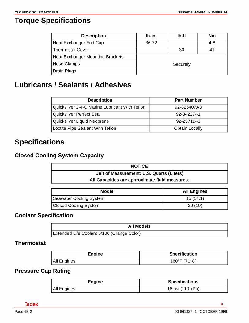
Torque Specifications
Description lb-in. lb-ft Nm
Heat Exchanger End Cap 36-72 4-8
Thermostat Cover 30 41
Heat Exchanger Mounting Brackets
Hose Clamps Securely
Drain Plugs
Lubricants / Sealants / Adhesives
Description Part Number
Quicksilver 2-4-C Marine Lubricant With Teflon 92-825407A3
Quicksilver Perfect Seal 92-34227--1
Quicksilver Liquid Neoprene 92-25711--3
Loctite Pipe Sealant With Teflon Obtain Locally
Specifications
Closed Cooling System Capacity
NOTICE
Unit of Measurement: U.S. Quarts (Liters)All Capacities are approximate fluid measures.
Model All Engines
Seawater Cooling System 15 (14.1)
Closed Cooling System 20 (19)
Coolant Specification
All Models
Extended Life Coolant 5/100 (Orange Color)
Thermostat
Engine Specification
All Engines 160°F (71°C)
Pressure Cap Rating
Engine Specifications
All Engines 16 psi (110 kPa)
CLOSED COOLED MODELSSERVICE MANUAL NUMBER 24
90-861327--1 OCTOBER 1999 Page 6B-3
Description
The cooling system is composed of two separate subsystems: the seawater system and theclosed cooling system. The seawater system is similar in function to the fan used in an auto-mobile because it absorbs heat from the closed cooling system as it passes through the heatexchanger. The closed cooling system is similar in function to the rest of the cooling systemin an automobile.
The coolant recovery system keeps the reservoir full. Normal coolant overflow into recoverybottle is approximately 1/2 pint (230 mL) during warm-up. The coolant recovery systemdraws coolant back into the reservoir from the recovery bottle as the engine cools. As longas there is coolant in the recovery bottle, the reservoir should remain completely full. If not,there is a vacuum leak, usually at the hose leaving the reservoir or the gasket under the re-covery filler cap.
IMPORTANT: The coolant (antifreeze) flows around the outside of the cooling tubeswhile seawater flows through the inside of the cooling tubes in the heat exchanger.
Coolant Recommendations
CAUTIONAlcohol or Methanol base antifreeze or plain water are not recommended for use infresh water section of cooling system at any time.
NOTE: All factory installed closed cooling systems come filled with Extended Life Coolant.This antifreeze requires draining and replacing every five years or 1000 hours of operation,whichever comes first. For best results any “top-off” fluid used should be Extended LifeCoolant. If Extended Life Coolant is unavailable, any type of ethylene glycol based anti-freeze may be used, but it will require the draining and replacing of the coolant every twoyears or 400 hours of operation, whichever comes first.
In areas where the possibility of freezing DOES NOT exist, it is permissible to use solutionof rust inhibitor and water (mixed to manufacturer’s recommendations).
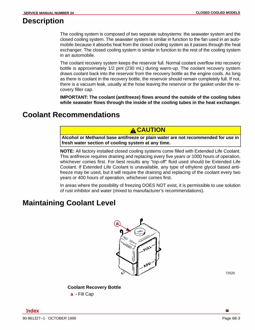
Maintaining Coolant Level
72520
a
Coolant Recovery Bottlea - Fill Cap
CLOSED COOLED MODELS SERVICE MANUAL NUMBER 24
Page 6B-4 90-861327--1 OCTOBER 1999
Before starting engine each day, ensure that coolant is visible in coolant recovery bottle.
If coolant is not visible, check fresh water section of cooling system (including coolant recov-ery system) for leaks and repair. Refill fresh water section with recommended coolant solu-tion as outlined under “Changing Coolant,” following.
If coolant is visible, start engine and run until it reaches normal operating temperature, thenrecheck coolant level in coolant recovery bottle. Coolant level MUST be between the ADDand FULL marks (on front of bottle).
WARNINGAllow engine to cool before removing pressure cap. Sudden loss of pressure couldcause hot coolant to boil and discharge violently. After engine has cooled, turn cap1/4 turn to allow any pressure to escape slowly, then push down and remove cap.
If level is low, remove fill cap from coolant recovery bottle and add required amount of cool-ant solution. Refer to “Coolant recommendations” in this section.
IMPORTANT: ALCOHOL OR METHANOL BASE ANTIFREEZE OR PLAIN WATER ARENOT RECOMMENDED FOR USE IN COOLING SYSTEM AT ANY TIME. In areas whereethylene glycol is not available, and the possibility of freezing does not exist, it ispermissible to use a solution of rust inhibitor and pure, soft water (mixed tomanufacturer’s recommendations).
Occasionally, ensure that coolant recovery system is functioning properly by removingpressure cap from heat exchanger and checking level. Coolant level should be up to bottomof heat exchanger filler neck. If low, examine entire fresh water section (especially coolantrecovery system) for leaks and repair.
IMPORTANT: When reinstalling pressure cap, tighten it until it contacts stops on fillerneck.
Pressure Cap Maintenance
Pressure cap should maintain pressure in fresh water section of closed cooling system atnormal engine operating temperature. This raises the boiling point of the coolant, therebyincreasing the efficiency of the cooling system. To help ensure proper operation, cap shouldbe cleaned, inspected and pressure tested periodically as follows:
WARNINGAllow engine to cool before removing pressure cap. Sudden loss of pressure couldcause hot coolant to boil and discharge violently. After engine has cooled, turn cap1/4 turn to allow any pressure to escape slowly, then push down and turn cap all theway off.
1. Remove pressure cap from heat exchanger.
2. Wash cap with clean water to remove any deposits or debris from sealing surfaces.
3. Inspect rubber seal on cap for cuts, cracks or other signs of deterioration. If seal is dam-aged, cap MUST be replaced.
4. Inspect coolant recovery gasket for deterioration and replace if bad.
CLOSED COOLED MODELSSERVICE MANUAL NUMBER 24
90-861327--1 OCTOBER 1999 Page 6B-5
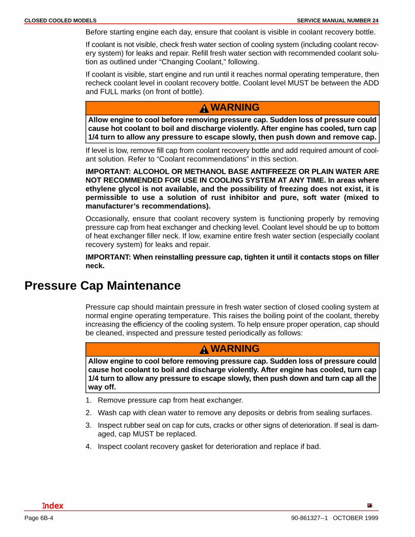
5. Check condition of locking tabs on cap. Replace cap if tabs are bent or cracked.
6. Check gasket for cracks or other damage.
IMPORTANT: Cap MUST be replaced if damaged.
72714
a
b
c
a - Rubber Sealb - Gasketc - Locking Tabs (1 Hidden)
7. Refer to “Testing Pressure Cap” and test pressure cap as outlined.
8. Clean sealing surfaces on heat exchanger filler neck with a cloth. Inspect surfaces forany damage or deposits that may prevent cap from sealing properly.
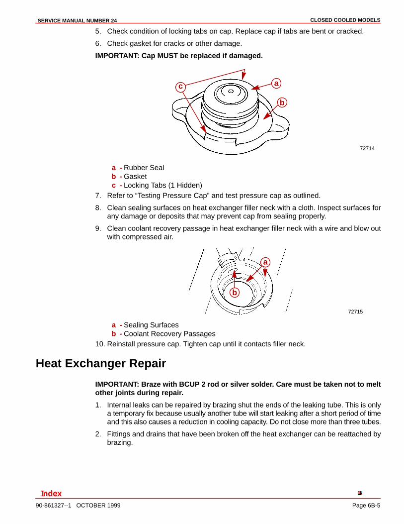
9. Clean coolant recovery passage in heat exchanger filler neck with a wire and blow outwith compressed air.
72715
a
b
a - Sealing Surfacesb - Coolant Recovery Passages
10. Reinstall pressure cap. Tighten cap until it contacts filler neck.
Heat Exchanger Repair
IMPORTANT: Braze with BCUP 2 rod or silver solder. Care must be taken not to meltother joints during repair.
1. Internal leaks can be repaired by brazing shut the ends of the leaking tube. This is onlya temporary fix because usually another tube will start leaking after a short period of timeand this also causes a reduction in cooling capacity. Do not close more than three tubes.
2. Fittings and drains that have been broken off the heat exchanger can be reattached bybrazing.

CLOSED COOLED MODELS SERVICE MANUAL NUMBER 24
Page 6B-6 90-861327--1 OCTOBER 1999
Testing Closed Cooling System
Testing Coolant for Alkalinity
WARNINGAllow engine to cool before removing pressure cap as sudden loss of pressurecould cause hot coolant to boil and discharge violently. After engine has cooled,turn cap 1/4 turn to allow any pressure to escape slowly, then push down and turncap all the way off.
Coolant in fresh water section should be changed per Maintenance Schedule recommenda-tions and should be checked for alkalinity at least once between change intervals. To checkcoolant for alkalinity, proceed as follows:
1. Obtain pink litmus paper from a local supplier (drug store, pet shop, etc.).
2. Remove pressure cap from heat exchanger and insert one end of litmus paper into cool-ant.
3. If pink litmus paper turns blue, coolant is alkaline and need not be replaced.
4. If pink litmus paper remains pink, coolant is not alkaline and MUST BE REPLACED,as explained under “Changing Coolant.”
Pressure Testing System
WARNINGAllow engine to cool before removing pressure cap. Sudden loss of pressure couldcause hot coolant to boil and discharge violently. After engine has cooled, turn cap1/4 turn to allow any pressure to escape slowly, then push down and turn cap all theway off.
If coolant section of closed cooling system is suspected of leaking or not holding sufficientpressure, and no visible signs of leakage can be found, perform the following test:
1. Remove pressure cap from heat exchanger or reservoir.
2. Clean, inspect and pressure test pressure cap, as outlined in “Testing Pressure Cap.”
3. Clean inside of filler neck to remove any deposits or debris. Examine lower inside seal-ing surface for damage. Surface must be perfectly smooth to achieve a good seal be-tween it and rubber seal on cap. Also check locking cams on sides of filler neck to besure that they are not bent or damaged.
4. Adjust coolant level in fresh water section to 1 in. (25 mm) below filler neck.
5. Attach an automotive-type cooling system pressure tester to filler neck and pressurizeclosed cooling section to amount specified in following chart.
Pressure Cap Rating Amount of Pressure Applied to Closed Cooling System
16 psi (110 kPa) 20 psi (138 kPa)
6. Observe gauge reading for approximately two minutes; pressure should not drop duringthis time. If pressure drops, proceed with the following steps until leakage is found.
7. While maintaining specified pressure on closed cooling section, visually inspect exter-nal portion of cooling system (hoses, gaskets, drain plugs, petcocks, core plugs, circu-lating pump seal, etc.) for leakage. Also listen closely for bubbling or hissing.
8. Refer to “Testing Heat Exchanger” in this section and test as outlined.
CLOSED COOLED MODELSSERVICE MANUAL NUMBER 24
90-861327--1 OCTOBER 1999 Page 6B-7
9. If no leakage could be found in above steps, engine is leaking internally. Leaking maybe caused by one or more of the following: (1) loose cylinder head bolts or damagedgasket, (2) loose intake manifold bolts or damaged gasket, (3) loose exhaust elbow ordistribution block retaining nuts or damaged gasket, (4) cracked or porous cylinder heador block, or (5) cracked or porous exhaust manifold. Proceed as follows until locationof internal leak is found.
a. Start engine. Re-pressurize system to previously specified amount and observepressure gauge on tester. If needle in gauge vibrates, compression or combustionis leaking into closed cooling section from a leak in the combustion chamber. Exactcylinders where leakage is taking place can sometimes be found by removing sparkplug wires (one at a time) while observing pressure gauge. Vibration will decreaseor stop when plug wire is removed from leaking cylinder. Stop engine.
b. Remove spark plugs (one at a time) from cylinders and examine for presence ofcoolant. A spark plug that is perfectly clean or milky appearing is a sure indicationof a leak.
c. Drain oil from engine and examine for coolant. Oil will usually be milky if coolant ispresent. If coolant is present, remove engine from boat and drop the oil pan. Withengine in the upright position, re-pressurize closed cooling section to previouslyspecified amount and examine internal surfaces of engine to locate leak.
d. If no leakage can be found in above steps, entire engine must be disassembled andinspected for leakage.
Testing for Cylinder Head Gasket LeakA leaking head gasket will cause combustion gas to be forced into the cooling system. Themixture of coolant and tiny air bubbles is a poor heat conductor and will overheat an enginequickly. Compression tests or cooling system pressure check normally will not detect theleak because the test pressure is far below the combustion pressures that cause the leak.An effective test is as follows:
IMPORTANT: Run boat in lake for this test. It is best to run the engine at or abovecruising speed during this test. Usually a failed head gasket will not cause the engineto overheat below cruising speed.
1. Install a clear plastic hose between the reservoir and coolant recovery bottle. Use a 2-3ft. (610-910 mm) long hose for this test.
2. Route this hose so a “U” is formed.
3. Put enough coolant into hose to fill the center 4 or 5 inches (100-130 mm) of the “U.”
4. Observe the “U” while the engine is running.
a. During Idle and Warm-Up: Some coolant and/or air will leave the reservoir.
b. During Cruising Speed (2500-3500 rpm): Coolant and/or air leaving the reservoirshould stop after approximately five minutes running at a given rpm. A leaking headgasket will produce air bubbling through the “U,” going to the coolant recovery bottle.The frequency and size of the bubbles will depend on the size of the leak.
c. At Higher Speeds (4000+ rpm): Normal operation is the same as described in “b”above. A failed head gasket will cause the bubbles to come faster and may beaccompanied by violent, intermittent bursts of coolant.

CLOSED COOLED MODELS SERVICE MANUAL NUMBER 24
Page 6B-8 90-861327--1 OCTOBER 1999
Do not confuse normal warm-up expansion with a failed head gasket. Normal warm-upproduces an intermittent flow of coolant that will stop within approximately five minutes ata given rpm. A head gasket leak will not stop because the one thing that marks a failed headgasket is the continued passage of air. This may be accompanied by violent, intermittentbursts of coolant leaving the reservoir. If coolant flows evenly from the reservoir at cruisingspeed, something other than the head gasket is causing the engine to overheat.
Testing Heat ExchangerFOR INTERNAL LEAK: An internal leak will cause coolant to go into the seawater circuitwhen pressure is put on the closed cooling circuit.
1. Remove a seawater hose from the exchanger. Do not drain the exchanger.
2. Pressurize the closed cooling circuit to 16-20 psi (110-138 kPa) with a radiator tester.
3. If seawater begins to flow from the nipple there is a leak.
FOR BLOCKAGE:
IMPORTANT: Seawater flows THROUGH the tubes in the exchanger. Closed coolingcoolant flows AROUND the tubes.
1. Remove end caps and inspect for any blockage in the seawater circuit (broken impellerblades, weeds, etc.).
2. Remove closed cooling circuit hoses and inspect the tubes just inside the nipples.Because the complete exchanger cannot be inspected, the heat exchanger should bereplaced if blockage is suspected.
Testing Pressure CapPressure cap is designed to maintain a pressure of approximately its rated capacity (referto “Specifications”) in closed cooling section once engine has attained operating tempera-ture. Cap should be cleaned, inspected and pressure-tested at regular tune-up intervals orwhenever cap is suspected of maintaining improper pressure as follows:
WARNINGAllow engine to cool before removing pressure cap. Sudden loss of pressure couldcause hot coolant to boil and discharge violently. After engine has cooled, turn cap1/4 turn to allow any pressure to escape slowly, then push down and turn cap all theway off.
1. Carefully remove pressure cap from reservoir or heat exchanger.
2. Wash cap with clean water to remove any deposits or debris from sealing surfaces.
3. Inspect gasket (if used) and rubber seal on cap for tears, cuts, cracks or other signs ofdeterioration. Replace gasket, if damaged, or entire cap if rubber seal is damaged.
4. Check condition of locking tabs on cap. Replace cap if tabs are bent or cracked.
CLOSED COOLED MODELSSERVICE MANUAL NUMBER 24
90-861327--1 OCTOBER 1999 Page 6B-9
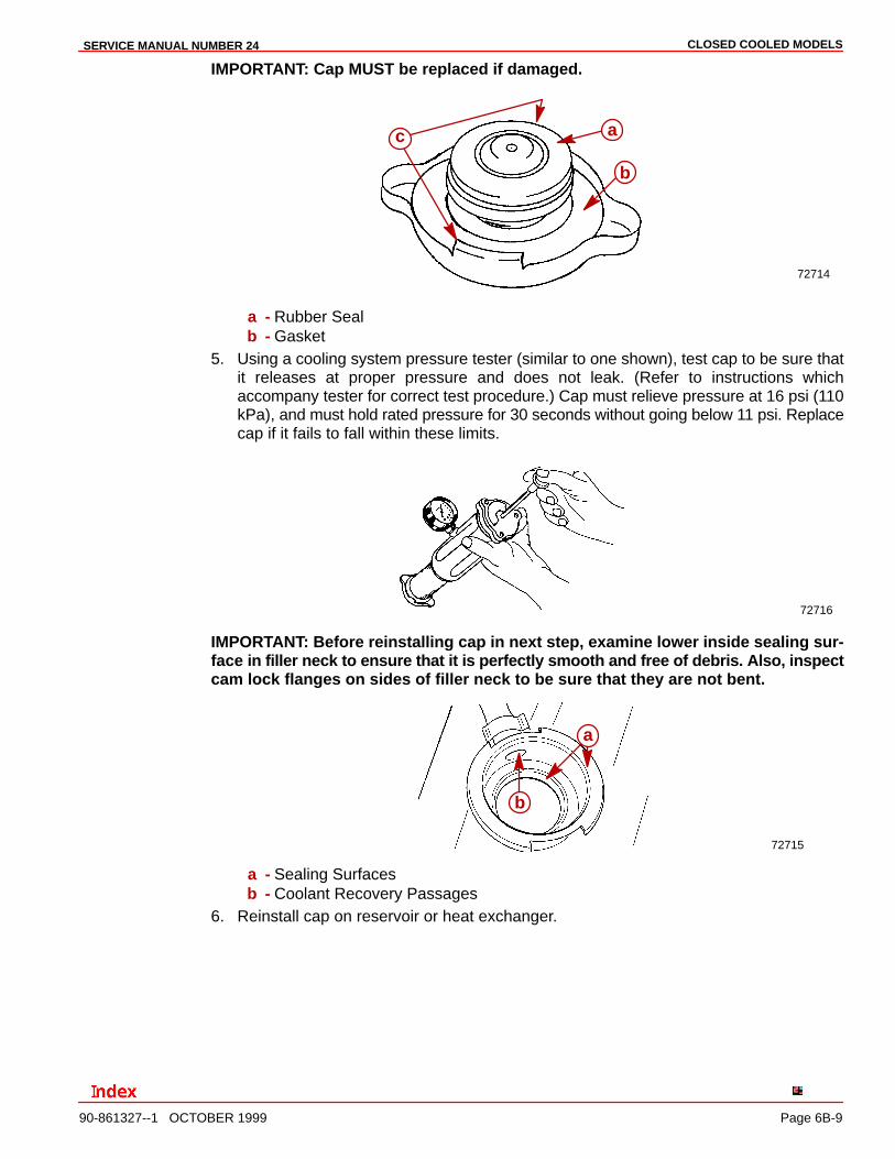
IMPORTANT: Cap MUST be replaced if damaged.
72714
a
b
c
a - Rubber Sealb - Gasket
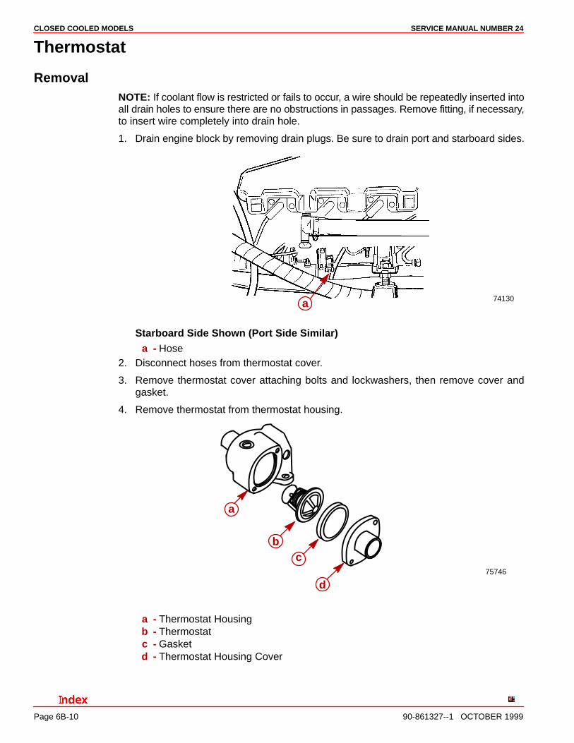
5. Using a cooling system pressure tester (similar to one shown), test cap to be sure thatit releases at proper pressure and does not leak. (Refer to instructions whichaccompany tester for correct test procedure.) Cap must relieve pressure at 16 psi (110kPa), and must hold rated pressure for 30 seconds without going below 11 psi. Replacecap if it fails to fall within these limits.
72716
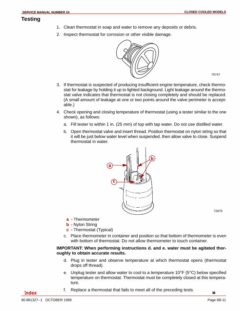
IMPORTANT: Before reinstalling cap in next step, examine lower inside sealing sur-face in filler neck to ensure that it is perfectly smooth and free of debris. Also, inspectcam lock flanges on sides of filler neck to be sure that they are not bent.
72715
a
b
a - Sealing Surfacesb - Coolant Recovery Passages
6. Reinstall cap on reservoir or heat exchanger.
CLOSED COOLED MODELS SERVICE MANUAL NUMBER 24
Page 6B-10 90-861327--1 OCTOBER 1999
Thermostat
RemovalNOTE: If coolant flow is restricted or fails to occur, a wire should be repeatedly inserted intoall drain holes to ensure there are no obstructions in passages. Remove fitting, if necessary,to insert wire completely into drain hole.
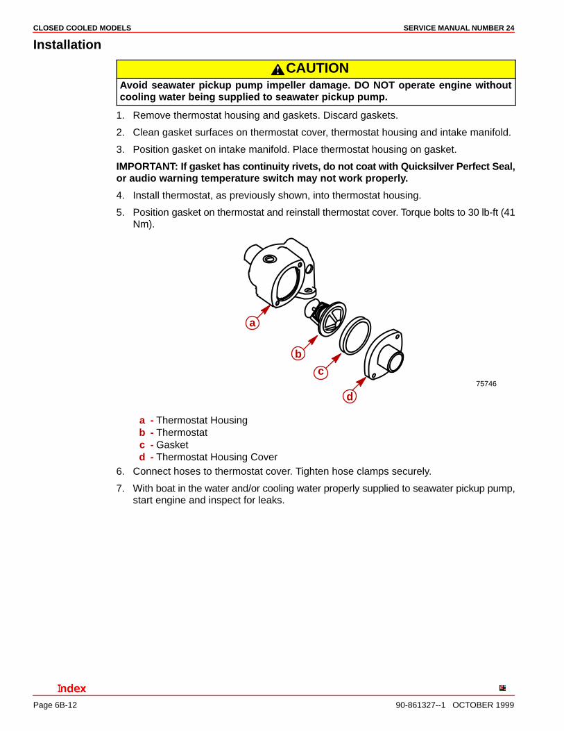
1. Drain engine block by removing drain plugs. Be sure to drain port and starboard sides.
74130a
Starboard Side Shown (Port Side Similar)a - Hose
2. Disconnect hoses from thermostat cover.
3. Remove thermostat cover attaching bolts and lockwashers, then remove cover andgasket.
4. Remove thermostat from thermostat housing.
75746
a
bc
d
a - Thermostat Housingb - Thermostatc - Gasketd - Thermostat Housing Cover
CLOSED COOLED MODELSSERVICE MANUAL NUMBER 24
90-861327--1 OCTOBER 1999 Page 6B-11
Testing1. Clean thermostat in soap and water to remove any deposits or debris.
2. Inspect thermostat for corrosion or other visible damage.
75747
3. If thermostat is suspected of producing insufficient engine temperature, check thermo-stat for leakage by holding it up to lighted background. Light leakage around the thermo-stat valve indicates that thermostat is not closing completely and should be replaced.(A small amount of leakage at one or two points around the valve perimeter is accept-able.)
4. Check opening and closing temperature of thermostat (using a tester similar to the oneshown), as follows:
a. Fill tester to within 1 in. (25 mm) of top with tap water. Do not use distilled water.
b. Open thermostat valve and insert thread. Position thermostat on nylon string so thatit will be just below water level when suspended, then allow valve to close. Suspendthermostat in water.
72675
ab
c
a - Thermometerb - Nylon Stringc - Thermostat (Typical)
c. Place thermometer in container and position so that bottom of thermometer is evenwith bottom of thermostat. Do not allow thermometer to touch container.
IMPORTANT: When performing instructions d. and e. water must be agitated thor-oughly to obtain accurate results.
d. Plug in tester and observe temperature at which thermostat opens (thermostatdrops off thread).
e. Unplug tester and allow water to cool to a temperature 10°F (5°C) below specifiedtemperature on thermostat. Thermostat must be completely closed at this tempera-ture.
f. Replace a thermostat that fails to meet all of the preceding tests.
CLOSED COOLED MODELS SERVICE MANUAL NUMBER 24
Page 6B-12 90-861327--1 OCTOBER 1999
Installation
CAUTIONAvoid seawater pickup pump impeller damage. DO NOT operate engine withoutcooling water being supplied to seawater pickup pump.
1. Remove thermostat housing and gaskets. Discard gaskets.
2. Clean gasket surfaces on thermostat cover, thermostat housing and intake manifold.
3. Position gasket on intake manifold. Place thermostat housing on gasket.
IMPORTANT: If gasket has continuity rivets, do not coat with Quicksilver Perfect Seal,or audio warning temperature switch may not work properly.
4. Install thermostat, as previously shown, into thermostat housing.
5. Position gasket on thermostat and reinstall thermostat cover. Torque bolts to 30 lb-ft (41Nm).
75746
a
b
c
d
a - Thermostat Housingb - Thermostatc - Gasketd - Thermostat Housing Cover
6. Connect hoses to thermostat cover. Tighten hose clamps securely.
7. With boat in the water and/or cooling water properly supplied to seawater pickup pump,start engine and inspect for leaks.

CLOSED COOLED MODELSSERVICE MANUAL NUMBER 24
90-861327--1 OCTOBER 1999 Page 6B-13
Changing Coolant
NOTICE
For information and procedures on draining the seawater cooling system ofSeawater Cooled (Raw–water) Models, refer to SECTION 6A. For information andprocedures on draining the Seawater Section of Closed Cooling (Coolant) Modelsrefer to SECTION 1B. For cold weather or extended storage, refer to SECTION 1B.
Closed Cooling SectionClosed cooling section of closed cooling system should be kept filled year-round withrecommended coolant solution. Do not drain closed cooling section for storage, as this willpromote rusting of internal surfaces. If engine will be exposed to freezing temperatures,make sure that closed cooling section is filled with Extended Life Coolant or an ethyleneglycol antifreeze and water solution, mixed to manufacturer’s recommended proportions,to protect engine to lowest temperature to which it will be exposed. If necessary, changecoolant using coolant specified in “Coolant Recommendations.”
Change IntervalsIf the closed cooling system is factory installed, drain and flush coolant from the closed cool-ing system at least every five years or 1000 hours of operation, whichever comes first. Itshould also be changed whenever exhaust gases have entered the system.
If the system is not factory installed or has had anti-freeze other than Extended Life Coolantadded, it must be changed every two years or 400 hours of operation, whichever comes first.
Draining Instructions
WARNINGAllow engine to cool before removing pressure cap. Sudden loss of pressure couldcause hot coolant to boil and discharge violently. After engine has cooled, turn cap1/4 turn to allow any pressure to escape slowly, then push down and turn cap all theway off.
IMPORTANT: A wire should be inserted into drain holes to ensure that foreignmaterial is not obstructing the drain holes. On some models with two piece petcock,removal of petcock may be required so that wire can be inserted completely into drainhole.
IMPORTANT: Engine must be as level as possible to ensure complete draining ofcooling system.
IMPORTANT: Closed cooling section must be kept filled year round with recom-mended coolant. If engine will be exposed to freezing temperatures, make sureclosed cooling section is filled with Extended Life Coolant or an ethylene glycol anti-freeze and water solution properly mixed to protect engine to lowest temperature towhich it will be exposed.
The following draining instructions apply to all engines equipped with closed cooling. Thelocation of petcocks that require opening and hoses that require removal are representedon the following pages for the individual engines.
IMPORTANT: Observe precautions previously outlined before proceeding.
1. Remove pressure cap from coolant tank.
2. Drain coolant from locations as shown in the “Draining Diagram.”
CLOSED COOLED MODELS SERVICE MANUAL NUMBER 24
Page 6B-14 90-861327--1 OCTOBER 1999
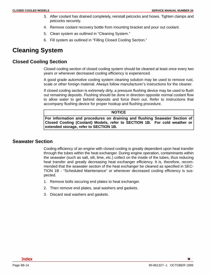
3. After coolant has drained completely, reinstall petcocks and hoses. Tighten clamps andpetcocks securely.
4. Remove coolant recovery bottle from mounting bracket and pour out coolant.
5. Clean system as outlined in “Cleaning System.”
6. Fill system as outlined in “Filling Closed Cooling Section.”
Cleaning System
Closed Cooling SectionClosed cooling section of closed cooling system should be cleaned at least once every twoyears or whenever decreased cooling efficiency is experienced.
A good grade automotive cooling system cleaning solution may be used to remove rust,scale or other foreign material. Always follow manufacturer’s instructions for the cleaner.
If closed cooling section is extremely dirty, a pressure flushing device may be used to flushout remaining deposits. Flushing should be done in direction opposite normal coolant flowto allow water to get behind deposits and force them out. Refer to instructions thataccompany flushing device for proper hookup and flushing procedure.
NOTICE
For information and procedures on draining and flushing Seawater Section ofClosed Cooling (Coolant) Models, refer to SECTION 1B. For cold weather orextended storage, refer to SECTION 1B.
Seawater SectionCooling efficiency of an engine with closed cooling is greatly dependent upon heat transferthrough the tubes within the heat exchanger. During engine operation, contaminants withinthe seawater (such as salt, silt, lime, etc.) collect on the inside of the tubes, thus reducingheat transfer and greatly decreasing heat exchanger efficiency. It is, therefore, recom-mended that the seawater section of the heat exchanger be cleaned as specified in SEC-TION 1B - “Scheduled Maintenance” or whenever decreased cooling efficiency is sus-pected.
1. Remove bolts securing end plates to heat exchanger.
2. Then remove end plates, seal washers and gaskets.
3. Discard seal washers and gaskets.
CLOSED COOLED MODELSSERVICE MANUAL NUMBER 24
90-861327--1 OCTOBER 1999 Page 6B-15
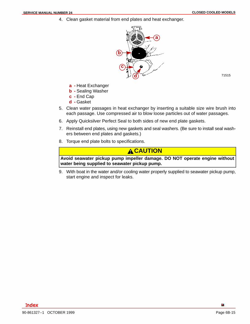
4. Clean gasket material from end plates and heat exchanger.
71515
a
b
c
d
a - Heat Exchangerb - Sealing Washerc - End Capd - Gasket
5. Clean water passages in heat exchanger by inserting a suitable size wire brush intoeach passage. Use compressed air to blow loose particles out of water passages.
6. Apply Quicksilver Perfect Seal to both sides of new end plate gaskets.
7. Reinstall end plates, using new gaskets and seal washers. (Be sure to install seal wash-ers between end plates and gaskets.)
8. Torque end plate bolts to specifications.
CAUTIONAvoid seawater pickup pump impeller damage. DO NOT operate engine withoutwater being supplied to seawater pickup pump.
9. With boat in the water and/or cooling water properly supplied to seawater pickup pump,start engine and inspect for leaks.
CLOSED COOLED MODELS SERVICE MANUAL NUMBER 24
Page 6B-16 90-861327--1 OCTOBER 1999
Filling Closed Cooling Section
CAUTIONAlcohol or Methanol base antifreeze or plain water are not recommended for use incoolant section of Closed Cooling System at any time.
It is recommended that coolant section of Closed Cooling System be filled with a 50/50 mix-ture of Extended Life Coolant and pure, soft water. This coolant MUST BE used regardlessof whether freezing temperatures are expected to provide adequate corrosion protection.In areas where Extended Life Coolant is not available and the possibility of freezing DOESNOT exist, it is permissible to use a solution of rust inhibitor and pure, soft water (mixed tomanufacturer’s recommendations).
NOTE: Coolant section capacity is approximately 18 U.S. Quarts (17 L).
1. Fill coolant section of Closed Cooling System with coolant mixture as follows:
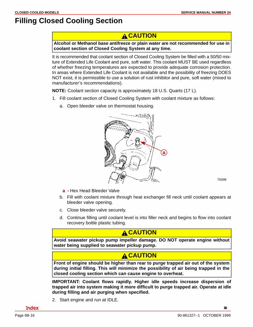
a. Open bleeder valve on thermostat housing.
75598
a
a - Hex Head Bleeder Valveb. Fill with coolant mixture through heat exchanger fill neck until coolant appears at
bleeder valve opening.
c. Close bleeder valve securely.
d. Continue filling until coolant level is into filler neck and begins to flow into coolantrecovery bottle plastic tubing.
CAUTIONAvoid seawater pickup pump impeller damage. DO NOT operate engine withoutwater being supplied to seawater pickup pump.
CAUTIONFront of engine should be higher than rear to purge trapped air out of the systemduring initial filling. This will minimize the possibility of air being trapped in theclosed cooling section which can cause engine to overheat.
IMPORTANT: Coolant flows rapidly. Higher idle speeds increase dispersion oftrapped air into system making it more difficult to purge trapped air. Operate at idleduring filling and air purging when specified.
2. Start engine and run at IDLE.
CLOSED COOLED MODELSSERVICE MANUAL NUMBER 24
90-861327--1 OCTOBER 1999 Page 6B-17
3. Add coolant solution to heat exchanger, as required, to maintain coolant level at fillerneck.
4. After engine has reached normal operating temperature thermostat is fully open andcoolant level remains constant, fill heat exchanger until coolant level is into filler neckand begins to flow into coolant recovery bottle plastic tubing.
5. Remove cap from coolant recovery reservoir and fill to “FULL” mark with coolant solu-tion.
6. Reinstall cap.
7. Lift recovery bottle and plastic tubing above heat exchanger filler neck. Allow coolantto flow down through tubing to purge air through filler neck fitting.
8. Install pressure cap on heat exchanger.
9. With engine still running, check hose connections, fittings and gaskets for leaks. Alsoobserve engine temperature gauge to make sure that engine operating temperature isnormal. If gauge indicates excessive temperature, stop engine immediately andexamine for cause.
WARNINGAllow engine to cool down before removing pressure cap. Sudden loss of pressurecould cause hot coolant to boil and discharge violently. After engine has cooled,turn cap 1/4-turn to allow any pressure to escape slowly, then push down and re-move cap.
10. Recheck coolant level after first boat test and add coolant, if necessary.
11. Maintain coolant level in coolant recovery reservoir between “Add” and “Full” marks withengine at normal operating temperature.
Coolant section of Closed Cooling System should be kept filled year around with recom-mended coolant solution. DO NOT drain coolant from fresh water section for storage, as thiswill promote rusting of internal surfaces. If engine will be exposed to freezing temperatures,make sure that coolant section is filled with Extended Life Coolant and water solution, mixedto manufacturer’s recommended proportion, to protect engine to lowest temperature towhich it will be exposed.
Auxiliary Hot Water Heater Installation
IMPORTANT: When connecting a cabin heater or hot water heater, certain require-ments must be met:
• Supply hose (from engine to heater) and return hose (from heater to engine)MUST NOT EXCEED 5/8 in. (16 mm) I.D. (inside diameter).
• Make heater connections ONLY at locations described in the following instruc-tions.
• Check complete system for leaks after heater is connected into cooling sys-tem.
• Check for overheating condition (of engine) after heater is connected.
CLOSED COOLED MODELS SERVICE MANUAL NUMBER 24
Page 6B-18 90-861327--1 OCTOBER 1999
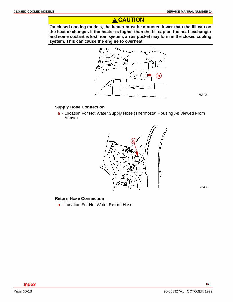
CAUTIONOn closed cooling models, the heater must be mounted lower than the fill cap onthe heat exchanger. If the heater is higher than the fill cap on the heat exchangerand some coolant is lost from system, an air pocket may form in the closed coolingsystem. This can cause the engine to overheat.
75503
a
Supply Hose Connectiona - Location For Hot Water Supply Hose (Thermostat Housing As Viewed From
Above)
75480
a
Return Hose Connectiona - Location For Hot Water Return Hose

CLOSED COOLED MODELSSERVICE MANUAL NUMBER 24
90-861327--1 OCTOBER 1999 Page 6B-19
Heat Exchanger Bracket Hardware
74988
74745
75213
75598
a
a
bc
de f
f
g
g
i
ih
l
k
Typical Engine Showna - Gasketb - Heat Exchanger Bracket and Padsc - Thermostat Housingd - Screws, Stainless Steele - Bleeder Valvef - Thermostatg - Quad-Ring Sealh - Outer Diameter of Thermostati - Thermostat Coverj - Screws with Lockwashersk - Engine Temperature Gauge Senderl - ECT Sender
CLOSED COOLED MODELS SERVICE MANUAL NUMBER 24
Page 6B-20 90-861327--1 OCTOBER 1999
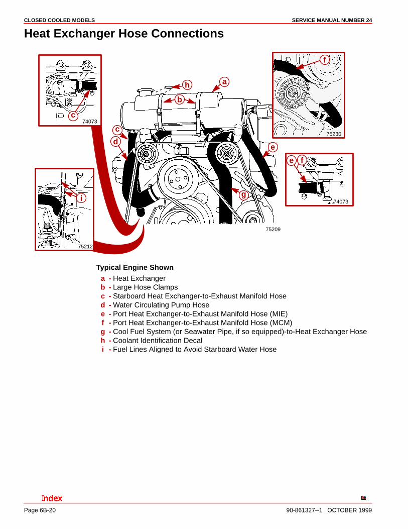
Heat Exchanger Hose Connections
75209
74073
74073
b
75212
75230
c
c
b
h a
f
fe
e
g
d
i
Typical Engine Showna - Heat Exchangerb - Large Hose Clampsc - Starboard Heat Exchanger-to-Exhaust Manifold Hosed - Water Circulating Pump Hosee - Port Heat Exchanger-to-Exhaust Manifold Hose (MIE)f - Port Heat Exchanger-to-Exhaust Manifold Hose (MCM)g - Cool Fuel System (or Seawater Pipe, if so equipped)-to-Heat Exchanger Hoseh - Coolant Identification Decali - Fuel Lines Aligned to Avoid Starboard Water Hose
CLOSED COOLED MODELSSERVICE MANUAL NUMBER 24
90-861327--1 OCTOBER 1999 Page 6B-21
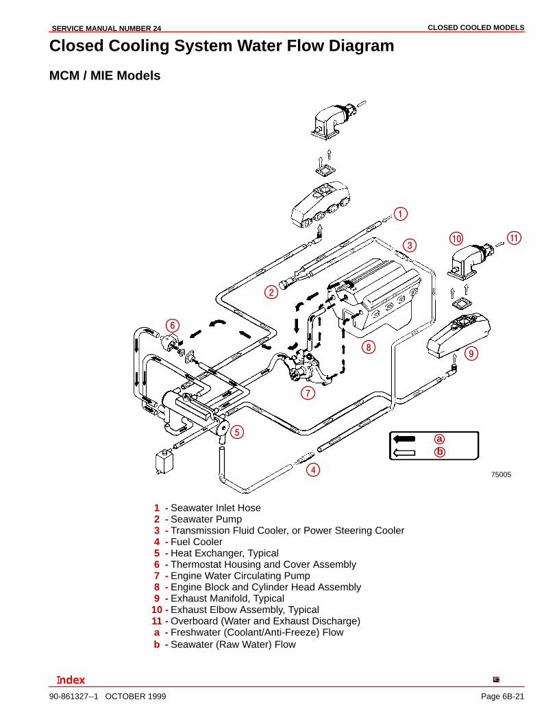
Closed Cooling System Water Flow Diagram
MCM / MIE Models
75005
�
�
�
�
�
�
�
�
�
ab
��
1 - Seawater Inlet Hose2 - Seawater Pump3 - Transmission Fluid Cooler, or Power Steering Cooler4 - Fuel Cooler5 - Heat Exchanger, Typical6 - Thermostat Housing and Cover Assembly7 - Engine Water Circulating Pump8 - Engine Block and Cylinder Head Assembly9 - Exhaust Manifold, Typical
10 - Exhaust Elbow Assembly, Typical11 - Overboard (Water and Exhaust Discharge)a - Freshwater (Coolant/Anti-Freeze) Flowb - Seawater (Raw Water) Flow
CLOSED COOLED MODELS SERVICE MANUAL NUMBER 24
Page 6B-22 90-861327--1 OCTOBER 1999
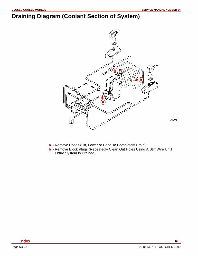
Draining Diagram (Coolant Section of System)
75005
a
b
b
a - Remove Hoses (Lift, Lower or Bend To Completely Drain).b - Remove Block Plugs (Repeatedly Clean Out Holes Using A Stiff Wire Until
Entire System Is Drained).
CLOSED COOLED MODELSSERVICE MANUAL NUMBER 24
90-861327--1 OCTOBER 1999 Page 6B-23
THIS PAGE IS INTENTIONALLY BLANK
CLOSED COOLED MODELS SERVICE MANUAL NUMBER 24
Page 6B-24 90-861327--1 OCTOBER 1999
THIS PAGE IS INTENTIONALLY BLANK