Embed Size (px)
Citation preview

X13A MODEL SHOWN
X13 SLICERX13X13AX13EX13AE
- NOTICE -This Manual is prepared for the use of trained Berkel ServiceTechnicians and should not be used by those not properlyqualified.
This manual is not intended to be all encompassing. If you havenot attended a Berkel Service School for this product, you shouldread, in its entirety, the repair procedure you wish to perform todetermine if you have the necessary tools, instruments and skillsrequired to perform the procedure. Procedures for which you donot have the necessary tools, instruments and skills should beperformed by a trained Berkel Service Technician.
The reproduction, transfer, sale or other use of this Manual,without the express written consent of Berkel, is prohibited.
This manual has been provided to you by ITW Food EquipmentGroup LLC ("ITW FEG") without charge and remains the propertyof ITW FEG, and by accepting this manual you agree that you willreturn it to ITW FEG promptly upon its request for such return atany time in the future.
SERVICE MANUAL
A product of BerkelF25332 Rev. A (0718)

TABLE OF CONTENTSSERVICE UPDATES . . . . . . . . . . . . . . . . . . . . . . . . . . . . . . . . . . . . . . . . . . . . . . . . . . . . . . . . . . . . . . . . . . . . . . . . . . . . . . . . . . . . . . . 4
UPDATES . . . . . . . . . . . . . . . . . . . . . . . . . . . . . . . . . . . . . . . . . . . . . . . . . . . . . . . . . . . . . . . . . . . . . . . . . . . . . . . . . . . . . . . . . . . . . . 4
GENERAL . . . . . . . . . . . . . . . . . . . . . . . . . . . . . . . . . . . . . . . . . . . . . . . . . . . . . . . . . . . . . . . . . . . . . . . . . . . . . . . . . . . . . . . . . . . . . . . . . . 5INTRODUCTION . . . . . . . . . . . . . . . . . . . . . . . . . . . . . . . . . . . . . . . . . . . . . . . . . . . . . . . . . . . . . . . . . . . . . . . . . . . . . . . . . . . . . . . 5OPERATION . . . . . . . . . . . . . . . . . . . . . . . . . . . . . . . . . . . . . . . . . . . . . . . . . . . . . . . . . . . . . . . . . . . . . . . . . . . . . . . . . . . . . . . . . . . 5CLEANING . . . . . . . . . . . . . . . . . . . . . . . . . . . . . . . . . . . . . . . . . . . . . . . . . . . . . . . . . . . . . . . . . . . . . . . . . . . . . . . . . . . . . . . . . . . . . 5SPECIFICATIONS . . . . . . . . . . . . . . . . . . . . . . . . . . . . . . . . . . . . . . . . . . . . . . . . . . . . . . . . . . . . . . . . . . . . . . . . . . . . . . . . . . . . . . 5LUBRICATION . . . . . . . . . . . . . . . . . . . . . . . . . . . . . . . . . . . . . . . . . . . . . . . . . . . . . . . . . . . . . . . . . . . . . . . . . . . . . . . . . . . . . . . . . 5TOOLS . . . . . . . . . . . . . . . . . . . . . . . . . . . . . . . . . . . . . . . . . . . . . . . . . . . . . . . . . . . . . . . . . . . . . . . . . . . . . . . . . . . . . . . . . . . . . . . . . 5
REMOVAL AND REPLACEMENT OF PARTS . . . . . . . . . . . . . . . . . . . . . . . . . . . . . . . . . . . . . . . . . . . . . . . . . . . . . . . . . . . . . . . 7SHARPENER . . . . . . . . . . . . . . . . . . . . . . . . . . . . . . . . . . . . . . . . . . . . . . . . . . . . . . . . . . . . . . . . . . . . . . . . . . . . . . . . . . . . . . . . . . 7
SHARPENER REMOVAL . . . . . . . . . . . . . . . . . . . . . . . . . . . . . . . . . . . . . . . . . . . . . . . . . . . . . . . . . . . . . . . . . . . . . . . . . . . 7SHARPENER DISASSEMBLY . . . . . . . . . . . . . . . . . . . . . . . . . . . . . . . . . . . . . . . . . . . . . . . . . . . . . . . . . . . . . . . . . . . . . . 7
PRODUCT TABLE . . . . . . . . . . . . . . . . . . . . . . . . . . . . . . . . . . . . . . . . . . . . . . . . . . . . . . . . . . . . . . . . . . . . . . . . . . . . . . . . . . . . . . 8PRODUCT TABLE REMOVAL . . . . . . . . . . . . . . . . . . . . . . . . . . . . . . . . . . . . . . . . . . . . . . . . . . . . . . . . . . . . . . . . . . . . . . 8
PRODUCT TABLE HANDLE . . . . . . . . . . . . . . . . . . . . . . . . . . . . . . . . . . . . . . . . . . . . . . . . . . . . . . . . . . . . . . . . . . . . . . . . . . . . 8PRODUCT TABLE HANDLE REMOVAL . . . . . . . . . . . . . . . . . . . . . . . . . . . . . . . . . . . . . . . . . . . . . . . . . . . . . . . . . . . . 8
PUSHER ARM ASSEMBLY . . . . . . . . . . . . . . . . . . . . . . . . . . . . . . . . . . . . . . . . . . . . . . . . . . . . . . . . . . . . . . . . . . . . . . . . . . . . . 9PUSHER ARM REMOVAL . . . . . . . . . . . . . . . . . . . . . . . . . . . . . . . . . . . . . . . . . . . . . . . . . . . . . . . . . . . . . . . . . . . . . . . . . . 9
ARM ASSEMBLY . . . . . . . . . . . . . . . . . . . . . . . . . . . . . . . . . . . . . . . . . . . . . . . . . . . . . . . . . . . . . . . . . . . . . . . . . . . . . . . . . . . . . . . 9ARM ASSEMBLY REMOVAL . . . . . . . . . . . . . . . . . . . . . . . . . . . . . . . . . . . . . . . . . . . . . . . . . . . . . . . . . . . . . . . . . . . . . . . 9ARM DISASSEMBLY . . . . . . . . . . . . . . . . . . . . . . . . . . . . . . . . . . . . . . . . . . . . . . . . . . . . . . . . . . . . . . . . . . . . . . . . . . . . . . 11
CENTER PLATE . . . . . . . . . . . . . . . . . . . . . . . . . . . . . . . . . . . . . . . . . . . . . . . . . . . . . . . . . . . . . . . . . . . . . . . . . . . . . . . . . . . . . . 12CENTER PLATE REMOVAL . . . . . . . . . . . . . . . . . . . . . . . . . . . . . . . . . . . . . . . . . . . . . . . . . . . . . . . . . . . . . . . . . . . . . . . 12CENTER PLATE INSTALLATION . . . . . . . . . . . . . . . . . . . . . . . . . . . . . . . . . . . . . . . . . . . . . . . . . . . . . . . . . . . . . . . . . . 12CENTER PLATE KNOB REMOVAL . . . . . . . . . . . . . . . . . . . . . . . . . . . . . . . . . . . . . . . . . . . . . . . . . . . . . . . . . . . . . . . . 13
KNIFE . . . . . . . . . . . . . . . . . . . . . . . . . . . . . . . . . . . . . . . . . . . . . . . . . . . . . . . . . . . . . . . . . . . . . . . . . . . . . . . . . . . . . . . . . . . . . . . . 13KNIFE REMOVAL . . . . . . . . . . . . . . . . . . . . . . . . . . . . . . . . . . . . . . . . . . . . . . . . . . . . . . . . . . . . . . . . . . . . . . . . . . . . . . . . . 13
RING GUARD . . . . . . . . . . . . . . . . . . . . . . . . . . . . . . . . . . . . . . . . . . . . . . . . . . . . . . . . . . . . . . . . . . . . . . . . . . . . . . . . . . . . . . . . . 14RING GUARD REMOVAL . . . . . . . . . . . . . . . . . . . . . . . . . . . . . . . . . . . . . . . . . . . . . . . . . . . . . . . . . . . . . . . . . . . . . . . . . 14
INDEX KNOB . . . . . . . . . . . . . . . . . . . . . . . . . . . . . . . . . . . . . . . . . . . . . . . . . . . . . . . . . . . . . . . . . . . . . . . . . . . . . . . . . . . . . . . . . 14BOTTOM COVER (X13A, X13AE) . . . . . . . . . . . . . . . . . . . . . . . . . . . . . . . . . . . . . . . . . . . . . . . . . . . . . . . . . . . . . . . . . . . . . 15
. . . . . . . . . . . . . . . . . . . . . . . . . . . . . . . . . . . . . . . . . . . . . . . . . . . . . . . . . . . . . . . . . . . . . . . . . . . . . . . . . . . . . . . . . . . . . . . . . . . . 15AUTODRIVE MECHANISM (X13A, X13AE) . . . . . . . . . . . . . . . . . . . . . . . . . . . . . . . . . . . . . . . . . . . . . . . . . . . . . . . . . . . . 15
AUTODRIVE MECHANISM REMOVAL . . . . . . . . . . . . . . . . . . . . . . . . . . . . . . . . . . . . . . . . . . . . . . . . . . . . . . . . . . . . 15AUTODRIVE MECHANISM DISASSEMBLY . . . . . . . . . . . . . . . . . . . . . . . . . . . . . . . . . . . . . . . . . . . . . . . . . . . . . . . 16AUTODRIVE MECHANISM INSTALLATION . . . . . . . . . . . . . . . . . . . . . . . . . . . . . . . . . . . . . . . . . . . . . . . . . . . . . . . 17
KNIFE MOTOR AND MOUNT ASSEMBLY . . . . . . . . . . . . . . . . . . . . . . . . . . . . . . . . . . . . . . . . . . . . . . . . . . . . . . . . . . . . . 17MOTOR AND MOUNT ASSEMBLY REMOVAL . . . . . . . . . . . . . . . . . . . . . . . . . . . . . . . . . . . . . . . . . . . . . . . . . . . . . 17MOTOR AND MOUNT ASSEMBLY INSTALLATION . . . . . . . . . . . . . . . . . . . . . . . . . . . . . . . . . . . . . . . . . . . . . . . . 18
DRIVE BELT . . . . . . . . . . . . . . . . . . . . . . . . . . . . . . . . . . . . . . . . . . . . . . . . . . . . . . . . . . . . . . . . . . . . . . . . . . . . . . . . . . . . . . . . . . 18DRIVE BELT REMOVAL . . . . . . . . . . . . . . . . . . . . . . . . . . . . . . . . . . . . . . . . . . . . . . . . . . . . . . . . . . . . . . . . . . . . . . . . . . 18DRIVE BELT INSTALLATION . . . . . . . . . . . . . . . . . . . . . . . . . . . . . . . . . . . . . . . . . . . . . . . . . . . . . . . . . . . . . . . . . . . . . . 18
KNIFE HUB ASSEMBLY . . . . . . . . . . . . . . . . . . . . . . . . . . . . . . . . . . . . . . . . . . . . . . . . . . . . . . . . . . . . . . . . . . . . . . . . . . . . . . 19KNIFE HUB ASSEMBLY REMOVAL . . . . . . . . . . . . . . . . . . . . . . . . . . . . . . . . . . . . . . . . . . . . . . . . . . . . . . . . . . . . . . . 19
CONTROL BOARD . . . . . . . . . . . . . . . . . . . . . . . . . . . . . . . . . . . . . . . . . . . . . . . . . . . . . . . . . . . . . . . . . . . . . . . . . . . . . . . . . . . . 19CONTROL BOARD REMOVAL . . . . . . . . . . . . . . . . . . . . . . . . . . . . . . . . . . . . . . . . . . . . . . . . . . . . . . . . . . . . . . . . . . . . 19
KICK STAND . . . . . . . . . . . . . . . . . . . . . . . . . . . . . . . . . . . . . . . . . . . . . . . . . . . . . . . . . . . . . . . . . . . . . . . . . . . . . . . . . . . . . . . . . . 20KICK STAND REMOVAL . . . . . . . . . . . . . . . . . . . . . . . . . . . . . . . . . . . . . . . . . . . . . . . . . . . . . . . . . . . . . . . . . . . . . . . . . . 20
GAUGE PLATE ASSEMBLY . . . . . . . . . . . . . . . . . . . . . . . . . . . . . . . . . . . . . . . . . . . . . . . . . . . . . . . . . . . . . . . . . . . . . . . . . . . 20GAUGE PLATE ASSEMBLY REMOVAL . . . . . . . . . . . . . . . . . . . . . . . . . . . . . . . . . . . . . . . . . . . . . . . . . . . . . . . . . . . 20
INDEX MECHANISM . . . . . . . . . . . . . . . . . . . . . . . . . . . . . . . . . . . . . . . . . . . . . . . . . . . . . . . . . . . . . . . . . . . . . . . . . . . . . . . . . . 20INDEX MECHANISM REMOVAL . . . . . . . . . . . . . . . . . . . . . . . . . . . . . . . . . . . . . . . . . . . . . . . . . . . . . . . . . . . . . . . . . . 20INDEX MECHANISM INSTALLATION . . . . . . . . . . . . . . . . . . . . . . . . . . . . . . . . . . . . . . . . . . . . . . . . . . . . . . . . . . . . . . 22
X13 SLICER
F25332 Rev. A (0718) Page 2 of 36

SERVICE PROCEDURES AND ADJUSTMENTS . . . . . . . . . . . . . . . . . . . . . . . . . . . . . . . . . . . . . . . . . . . . . . . . . . . . . . . . . . . 23PRODUCT TABLE ADJUSTMENTS . . . . . . . . . . . . . . . . . . . . . . . . . . . . . . . . . . . . . . . . . . . . . . . . . . . . . . . . . . . . . . . . . . . 23INTERLOCK CABLES / SUPPORT ARM ADJUSTMENT . . . . . . . . . . . . . . . . . . . . . . . . . . . . . . . . . . . . . . . . . . . . . . . 24INTERLOCK CABLES / INDEX KNOB ADJUSTMENTS . . . . . . . . . . . . . . . . . . . . . . . . . . . . . . . . . . . . . . . . . . . . . . . . 25GAUGE PLATE ADJUSTMENT . . . . . . . . . . . . . . . . . . . . . . . . . . . . . . . . . . . . . . . . . . . . . . . . . . . . . . . . . . . . . . . . . . . . . . . . 25SHARPENING . . . . . . . . . . . . . . . . . . . . . . . . . . . . . . . . . . . . . . . . . . . . . . . . . . . . . . . . . . . . . . . . . . . . . . . . . . . . . . . . . . . . . . . . 27CENTER PLATE CHECK . . . . . . . . . . . . . . . . . . . . . . . . . . . . . . . . . . . . . . . . . . . . . . . . . . . . . . . . . . . . . . . . . . . . . . . . . . . . . . 27AUTODRIVE ASSEMBLY ADJUSTMENTS (X13A, X13AE) . . . . . . . . . . . . . . . . . . . . . . . . . . . . . . . . . . . . . . . . . . . . . 28
ECCENTRIC PIN ADJUSTMENT . . . . . . . . . . . . . . . . . . . . . . . . . . . . . . . . . . . . . . . . . . . . . . . . . . . . . . . . . . . . . . . . . . 28WICK REPLACEMENT . . . . . . . . . . . . . . . . . . . . . . . . . . . . . . . . . . . . . . . . . . . . . . . . . . . . . . . . . . . . . . . . . . . . . . . . . . . . . . . . 28SLIDE BAR SWITCH TEST (X13, X13A) . . . . . . . . . . . . . . . . . . . . . . . . . . . . . . . . . . . . . . . . . . . . . . . . . . . . . . . . . . . . . . . 29CARRIAGE SENSOR TEST (X13, X13A) . . . . . . . . . . . . . . . . . . . . . . . . . . . . . . . . . . . . . . . . . . . . . . . . . . . . . . . . . . . . . . 30KNIFE MOTOR OHM TEST . . . . . . . . . . . . . . . . . . . . . . . . . . . . . . . . . . . . . . . . . . . . . . . . . . . . . . . . . . . . . . . . . . . . . . . . . . . 30CIRCUIT BREAKER TEST . . . . . . . . . . . . . . . . . . . . . . . . . . . . . . . . . . . . . . . . . . . . . . . . . . . . . . . . . . . . . . . . . . . . . . . . . . . . 31
ELECTRICAL OPERATION . . . . . . . . . . . . . . . . . . . . . . . . . . . . . . . . . . . . . . . . . . . . . . . . . . . . . . . . . . . . . . . . . . . . . . . . . . . . . . . . 32COMPONENT FUNCTION . . . . . . . . . . . . . . . . . . . . . . . . . . . . . . . . . . . . . . . . . . . . . . . . . . . . . . . . . . . . . . . . . . . . . . . . . . . . 32ERROR CODE TEST . . . . . . . . . . . . . . . . . . . . . . . . . . . . . . . . . . . . . . . . . . . . . . . . . . . . . . . . . . . . . . . . . . . . . . . . . . . . . . . . . . 32WIRING DIAGRAMS WITH SEQUENCE OF OPERATIONS . . . . . . . . . . . . . . . . . . . . . . . . . . . . . . . . . . . . . . . . . . . . 32
X13 & X13E SEQUENCE OF OPERATION . . . . . . . . . . . . . . . . . . . . . . . . . . . . . . . . . . . . . . . . . . . . . . . . . . . . . . . . 32X13A & X13AE SEQUENCE OF OPERATION . . . . . . . . . . . . . . . . . . . . . . . . . . . . . . . . . . . . . . . . . . . . . . . . . . . . . 33
TROUBLESHOOTING . . . . . . . . . . . . . . . . . . . . . . . . . . . . . . . . . . . . . . . . . . . . . . . . . . . . . . . . . . . . . . . . . . . . . . . . . . . . . . . . . . . . . 36TROUBLESHOOTING TABLE . . . . . . . . . . . . . . . . . . . . . . . . . . . . . . . . . . . . . . . . . . . . . . . . . . . . . . . . . . . . . . . . . . . . . . . . . 36
X13 SLICER
© BERKEL 2018Page 3 of 36 F25332 Rev. A (0718)

SERVICE UPDATES
UPDATES
July, 2018• Added INDEX KNOB.
X13 SLICER - SERVICE UPDATES
F25332 Rev. A (0718) Page 4 of 36
GENERAL
INTRODUCTION
This manual is for the Berkel X13 Slicer. Proceduresin this manual will apply to all models unless specified.Pictures and illustrations will be of model X13A unlessotherwise noted.
All of the information, illustrations and specificationscontained in this manual are based on the latestproduct information available at the time of printing.
Models
X13 Manual slicer withinterlocks
X13A Automatic slicer withinterlocks
X13E Manual slicer withoutinterlocks
X13AE Automatic slicer withoutinterlocks
OPERATION
Refer to the Instruction Manual for specific operatinginstructions.
CLEANING
Refer to the Instruction Manual for specific cleaninginstructions.
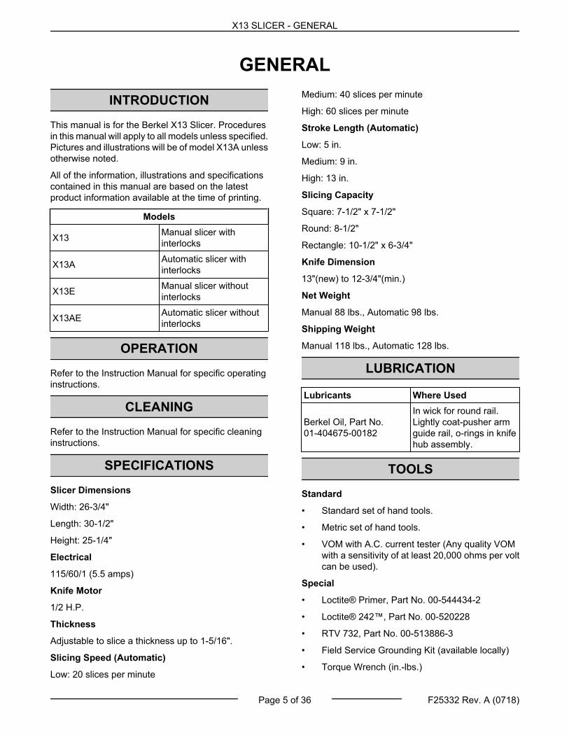
SPECIFICATIONS
Slicer Dimensions
Width: 26-3/4"
Length: 30-1/2"
Height: 25-1/4"
Electrical
115/60/1 (5.5 amps)
Knife Motor
1/2 H.P.
Thickness
Adjustable to slice a thickness up to 1-5/16".
Slicing Speed (Automatic)
Low: 20 slices per minute
Medium: 40 slices per minute
High: 60 slices per minute
Stroke Length (Automatic)
Low: 5 in.
Medium: 9 in.
High: 13 in.
Slicing Capacity
Square: 7-1/2" x 7-1/2"
Round: 8-1/2"
Rectangle: 10-1/2" x 6-3/4"
Knife Dimension
13"(new) to 12-3/4"(min.)
Net Weight
Manual 88 lbs., Automatic 98 lbs.
Shipping Weight
Manual 118 lbs., Automatic 128 lbs.
LUBRICATION
Lubricants Where Used
Berkel Oil, Part No.01-404675-00182
In wick for round rail.Lightly coat-pusher armguide rail, o-rings in knifehub assembly.
TOOLS
Standard
• Standard set of hand tools.
• Metric set of hand tools.
• VOM with A.C. current tester (Any quality VOMwith a sensitivity of at least 20,000 ohms per voltcan be used).
Special
• Loctite® Primer, Part No. 00-544434-2
• Loctite® 242™, Part No. 00-520228
• RTV 732, Part No. 00-513886-3
• Field Service Grounding Kit (available locally)
• Torque Wrench (in.-lbs.)
X13 SLICER - GENERAL
Page 5 of 36 F25332 Rev. A (0718)

Magnet PolarityHome Position (+) North out
Auto Clip Assembly (-) South out
Timer Assembly (+) North out
Sharpener (+) North out
Index Mechanism (-) South out
Use another magnet on the slicer to verify polarity ofa replacement magnet. (Opposites attract)
X13 SLICER - GENERAL
F25332 Rev. A (0718) Page 6 of 36

REMOVAL AND REPLACEMENT OF PARTS
SHARPENER
Sharpener Removal
Disconnect the electrical power tothe machine and follow lockout /tagout procedures.
1. Press down on lower tab.
Fig. 1
2. Remove sharpener.
3. Reverse procedure to install.
4. Check slicer for proper operation.
Sharpener DisassemblyNOTE: Remove only those parts required to accesspart(s) being replaced.
Fig. 2
1. Remove deburring assembly.
A. Remove nut (15) and washer (14).
NOTE: Parts (15), (17), (11), and (21) are left handthreaded on some older sharpeners.
B. Remove deburring stone (13) and skirt (12).
C. Remove e-clip (10), slide out shaft (5) whileholding spring (16).
D. Remove spring (16) and deburring frame (9)assembly.
1) Remove e-clip (6).
2) Remove bushing (7).
3) Remove spring (8, in compression).
2. Remove sharpening assembly.
A. Remove nut (17) and washer (18).
B. Remove sharpening stone (19) and skirt(20).
C. Remove e-clip (1).
D. Remove washer (2), fiber washer (24),bushing (23), spring (22, in compression),and shaft (21).
3. Reassemble sharpener in reverse order.
X13 SLICER - REMOVAL AND REPLACEMENT OF PARTS
Page 7 of 36 F25332 Rev. A (0718)

NOTE: Make sure tab on top of deburring frame (9)goes under lip (4) on sharpener frame uponreinstallation.
4. Reinstall sharpener on slicer.
5. Check for proper knife sharpener operation.
PRODUCT TABLE
Product Table Removal
Disconnect the electrical power tothe machine and follow lockout /tagout procedures.
1. Place product table in home position and turnindex knob to "0".
2. Loosen product table knob.
Fig. 3
3. Slide product table off arm.
4. Reverse procedure to install.
NOTE: Make sure that dowel pin enters and rotatesactuator arm interlock ("pacman").
Fig. 4
5. Check slicer for proper operation.
PRODUCT TABLE HANDLE
Product Table Handle Removal
Disconnect the electrical power tothe machine and follow lockout /tagout procedures.
1. Remove product table as outlined underPRODUCT TABLE.
2. Remove three screws.
Fig. 5
3. Remove handle.
4. Reverse procedure to install.
NOTE: Seal handle ends with RTV.
5. Check slicer for proper operation.
X13 SLICER - REMOVAL AND REPLACEMENT OF PARTS
F25332 Rev. A (0718) Page 8 of 36

PUSHER ARM ASSEMBLY
Pusher Arm Removal
Disconnect the electrical power tothe machine and follow lockout /tagout procedures.
1. Remove product table as outlined underPRODUCT TABLE.
2. Remove two guide rail screws.
NOTE: Do not allow guide rail to rotate while removingthe screws.
Fig. 6
3. Remove pusher arm assembly from guide rail.
4. Turn pusher handle CCW while preventingpusher from rotating.
Fig. 7
5. Remove pusher from pusher handle and shaft.
6. Reverse procedure to install.
NOTE: Apply Loctite® primer and Loctite® 242™ tothreads of guide rail screws. Screws will backout ifLoctite® and primer is not used.
7. Check slicer for proper operation.
ARM ASSEMBLY
Arm Assembly Removal
Disconnect the electrical power tothe machine and follow lockout /tagout procedures.
NOTE: X13E and X13AE models are not equippedwith interlocks. When working on an E series model,proceed past any step that refers to interlocks.
1. Remove product table as outlined underPRODUCT TABLE.
2. Slide arm assembly all the way to end of stroke(X13E, X13AE).
3. Place slicer on its side, so it is resting on motorhousing.
4. Supporting the arm assembly, squeeze the slidebar to the unlocked position and lower assembly.
Fig. 8
5. Remove screws and clevis pin, move slide barguide out of way.
X13 SLICER - REMOVAL AND REPLACEMENT OF PARTS
Page 9 of 36 F25332 Rev. A (0718)

Fig. 9
NOTE: Push interlock cable to the left. DO NOT pullcable out (to the right).
6. Remove screw and washer securing other end ofslide bar.
7. Remove slide bar (noting orientation forreinstallation).
8. Push in tab and lift flex cable to disconnect(X13A, X13AE).
Fig. 10
9. Remove screws and square rail.
NOTE: Reposition arm assembly and remove bottomscrew first.
Fig. 11
10. Remove 2 screws securing round rail.
Fig. 12
11. Remove round rail and arm assembly.
12. Reverse procedure to install.
NOTE: Screws go in countersunk side of round rail.
A. Place primary autodrive belt in clipassembly. (X13A, X13AE)
Fig. 13
X13 SLICER - REMOVAL AND REPLACEMENT OF PARTS
F25332 Rev. A (0718) Page 10 of 36

B. Reconnect flex cable last, and make surecable is in front of guide assembly. (X13A,X13AE)
Fig. 14
13. Check slicer for proper operation.
Arm DisassemblyNOTE: Remove only those parts required to accesspart(s) being replaced.
1. Remove screws and arm sensor.
Fig. 15
2. Remove autodrive clutch plate screws.
Fig. 16
3. Remove autodrive clutch plate and clipassembly.
4. Remove screw, autodrive clutch crank, andclutch engage rod.
Fig. 17
5. Remove autodrive clutch cam, clutch pivot shaft,and spring disc.
X13 SLICER - REMOVAL AND REPLACEMENT OF PARTS
Page 11 of 36 F25332 Rev. A (0718)

Fig. 18
6. Remove screws, clamp, and clevis pin.
Fig. 19
7. Remove plugs and screws beneath plugs.
Fig. 20
8. Remove top plate assembly.
NOTE: Top plate assembly edge is sealed with RTV.
9. Reverse procedure to assemble.
10. Check slicer for proper operation.
CENTER PLATE
Center Plate Removal
Disconnect the electrical power tothe machine and follow lockout /tagout procedures.
1. Close gauge plate.
2. Move product table to home position.
3. Turn center plate knob CCW until it lines up withpost stud.
Fig. 21
4. Lift cover out and up.
Center Plate Installation
1. Place center plate on shoulder studs with knoblined up to fit over post stud.
X13 SLICER - REMOVAL AND REPLACEMENT OF PARTS
F25332 Rev. A (0718) Page 12 of 36

Fig. 22
2. Turn center plate knob CW until resistance stop.
3. Check slicer for proper operation.
Center Plate Knob Removal
1. Remove center plate as outlined above.
2. Remove retaining ring from back side of knob.
Fig. 23
3. Remove knob.
4. Reverse procedure to install.
5. Check slicer for proper operation.
KNIFE
Knife Removal
Disconnect the electrical power tothe machine and follow lockout /tagout procedures.
Electrical and grounding connections mustcomply with the applicable portions of theNational Electrical Code and / or other localelectrical codes.
NOTE: Replace knife if it is less than 12-3/4"diameter.
1. Remove product table as outlined underPRODUCT TABLE.
2. Reach under slicer and pull slide bar toward armassembly.
Fig. 24
3. Open gauge plate and tape knife edge.
Fig. 25
4. Remove bolt and washer.
NOTE: Place #2 phillips driver in knife hole againstlower ring guard mount. Use a rag to protect the ringguard mount and slicer body.
X13 SLICER - REMOVAL AND REPLACEMENT OF PARTS
Page 13 of 36 F25332 Rev. A (0718)
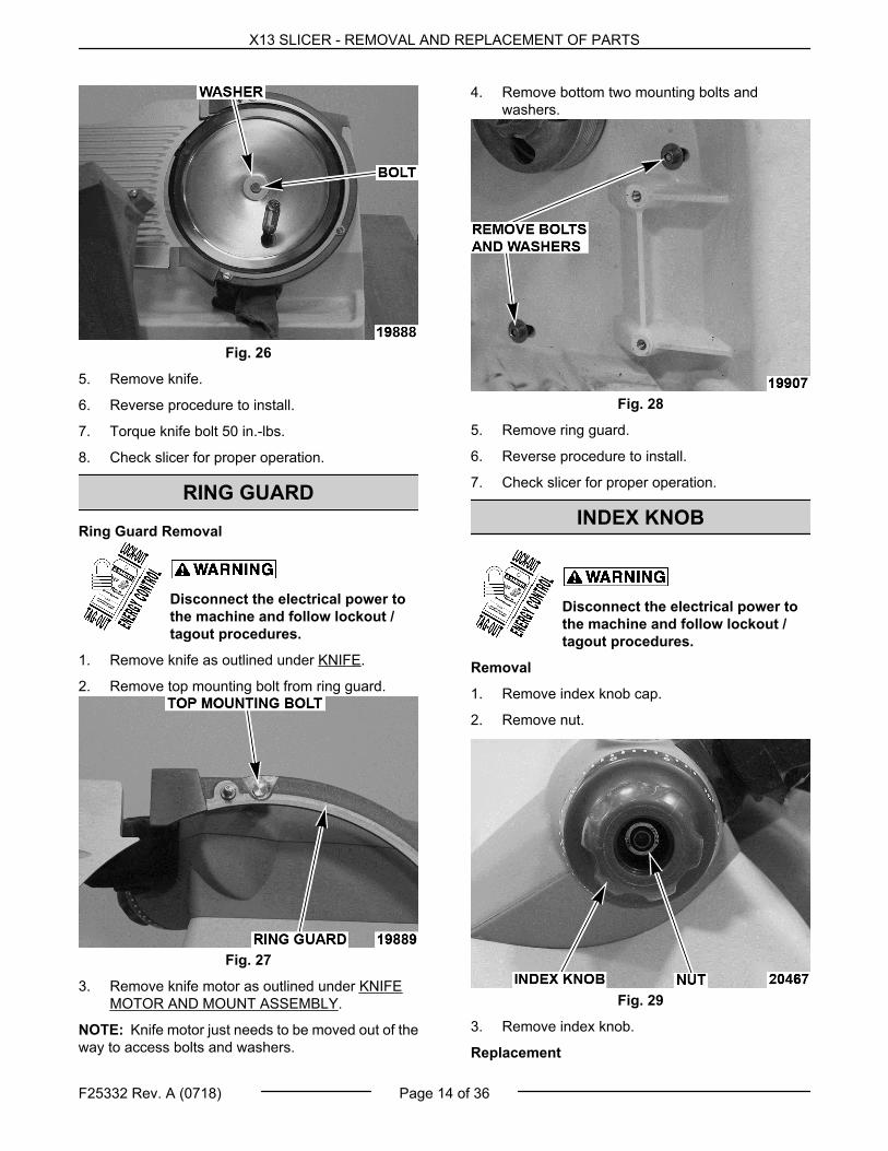
Fig. 26
5. Remove knife.
6. Reverse procedure to install.
7. Torque knife bolt 50 in.-lbs.
8. Check slicer for proper operation.
RING GUARD
Ring Guard Removal
Disconnect the electrical power tothe machine and follow lockout /tagout procedures.
1. Remove knife as outlined under KNIFE.
2. Remove top mounting bolt from ring guard.
Fig. 27
3. Remove knife motor as outlined under KNIFEMOTOR AND MOUNT ASSEMBLY.
NOTE: Knife motor just needs to be moved out of theway to access bolts and washers.
4. Remove bottom two mounting bolts andwashers.
Fig. 28
5. Remove ring guard.
6. Reverse procedure to install.
7. Check slicer for proper operation.
INDEX KNOB
Disconnect the electrical power tothe machine and follow lockout /tagout procedures.
Removal
1. Remove index knob cap.
2. Remove nut.
Fig. 29
3. Remove index knob.
Replacement
X13 SLICER - REMOVAL AND REPLACEMENT OF PARTS
F25332 Rev. A (0718) Page 14 of 36

1. Perform zero adjustment prior to replacing indexknob.
2. Replace index knob.
NOTE: Ensure end of cable goes into index knob holewithin spiral groove.
Fig. 30
3. Hold index knob at "0", and adjust index cam upor down to achieve proper height as outlined inGAUGE PLATE ADJUSTMENT.
Fig. 31
4. Hold index knob in place and tighten nut to 140in.-lbs.
5. Perform INTERLOCK CABLES / INDEX KNOBADJUSTMENTS.
6. Replace cap.
7. Check slicer for proper operation.
BOTTOM COVER (X13A, X13AE)
Disconnect the electrical power tothe machine and follow lockout /tagout procedures.
Electrical and grounding connections mustcomply with the applicable portions of theNational Electrical Code and / or other localelectrical codes.
1. Place slicer on its side, so it is resting on motorhousing.
2. Remove screws and unscrew foot.
Fig. 32
3. Remove bottom cover.
4. Reverse procedure to install.
A. Apply Loctite® primer and Loctite® 2440™to threads of foot.
5. Check slicer for proper operation.
AUTODRIVE MECHANISM (X13A,X13AE)
Autodrive Mechanism Removal
Disconnect the electrical power tothe machine and follow lockout /tagout procedures.
1. Remove bottom cover as outlined underBOTTOM COVER (X13A, X13AE).
X13 SLICER - REMOVAL AND REPLACEMENT OF PARTS
Page 15 of 36 F25332 Rev. A (0718)

2. Push in tab and lift flex cable to disconnect.
Fig. 33
3. Remove screws mounting J4 cable.
Fig. 34
4. Remove screws securing autodrive assembly.
A. Kickstand assembly is free to remove.
Fig. 35
5. Remove autodrive assembly.
Autodrive Mechanism DisassemblyNOTE: Remove only those parts required to accesspart(s) being replaced.
1. Remove screws securing autodrive motor.
Fig. 36
2. Remove autodrive motor and secondary belt.
3. Remove screws and washers securing autodrivetransmission housing.
NOTE: Transmission housing on opposite side.
X13 SLICER - REMOVAL AND REPLACEMENT OF PARTS
F25332 Rev. A (0718) Page 16 of 36

Fig. 37
4. Remove autodrive transmission housing,primary belt, and transmission.
5. Remove screws and washers securing tensionerassembly.
Fig. 38
6. Remove tensioner assembly.
7. Reverse procedure to assemble.
A. Set primary belt tension by applying handpressure to tensioner assembly.
NOTE: If the primary belt was replaced, you will needto adjust the eccentric pin as outlined under EccentricPin Adjustment .
8. Check slicer for proper operation.
Autodrive Mechanism Installation
1. Reverse removal procedure to install.
2. Place primary autodrive belt in clip assembly.
Fig. 39
A. Reconnect flex cable last, and make surecable is in front of guide assembly.
Fig. 40
3. Check slicer for proper operation.
KNIFE MOTOR AND MOUNTASSEMBLY
Motor and Mount Assembly Removal
Disconnect the electrical power tothe machine and follow lockout /tagout procedures.
1. Remove bottom cover as outlined underBOTTOM COVER (X13A, X13AE).
2. Remove autodrive assembly as outlined underAUTODRIVE MECHANISM (X13A, X13AE).
3. Access control board as outlined underCONTROL BOARD.
A. Remove motor wires from control board.
X13 SLICER - REMOVAL AND REPLACEMENT OF PARTS
Page 17 of 36 F25332 Rev. A (0718)
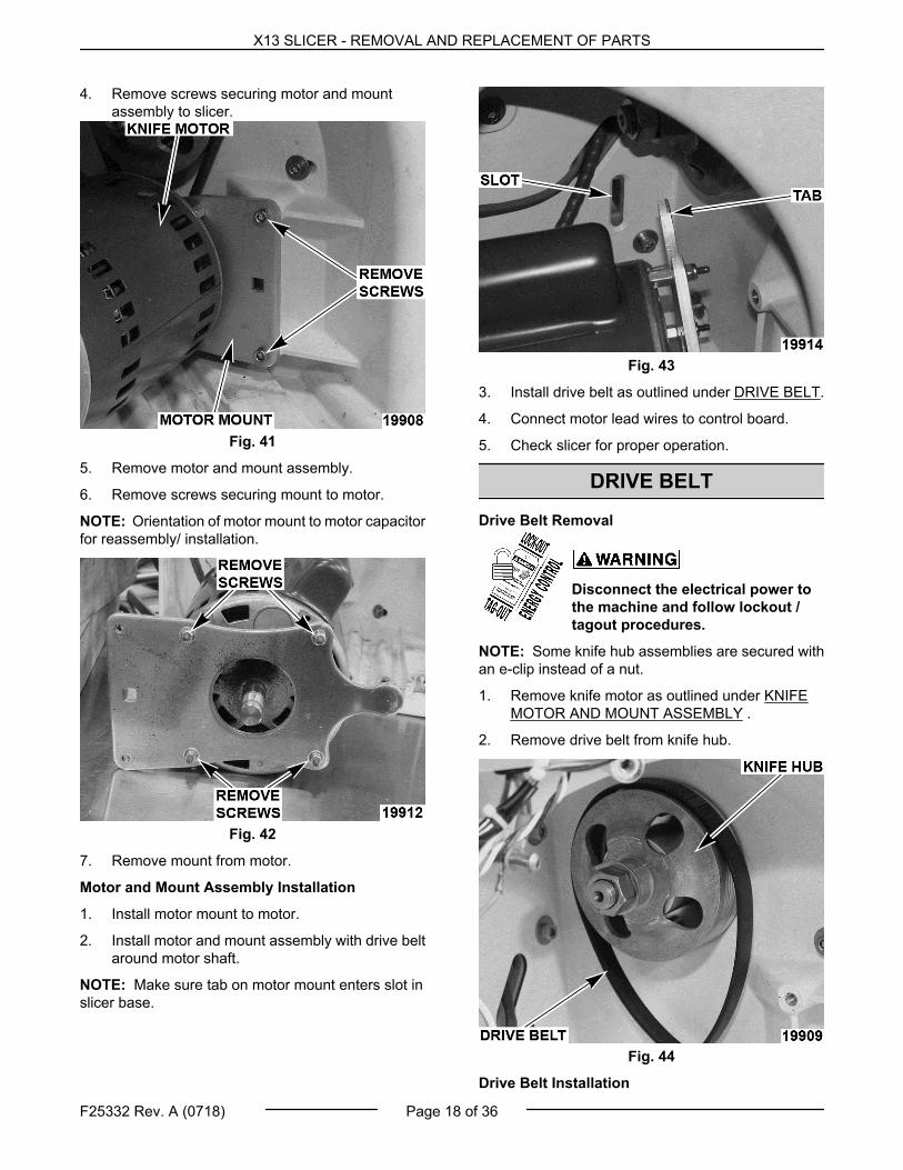
4. Remove screws securing motor and mountassembly to slicer.
Fig. 41
5. Remove motor and mount assembly.
6. Remove screws securing mount to motor.
NOTE: Orientation of motor mount to motor capacitorfor reassembly/ installation.
Fig. 42
7. Remove mount from motor.
Motor and Mount Assembly Installation
1. Install motor mount to motor.
2. Install motor and mount assembly with drive beltaround motor shaft.
NOTE: Make sure tab on motor mount enters slot inslicer base.
Fig. 43
3. Install drive belt as outlined under DRIVE BELT.
4. Connect motor lead wires to control board.
5. Check slicer for proper operation.
DRIVE BELT
Drive Belt Removal
Disconnect the electrical power tothe machine and follow lockout /tagout procedures.
NOTE: Some knife hub assemblies are secured withan e-clip instead of a nut.
1. Remove knife motor as outlined under KNIFEMOTOR AND MOUNT ASSEMBLY .
2. Remove drive belt from knife hub.
Fig. 44
Drive Belt Installation
X13 SLICER - REMOVAL AND REPLACEMENT OF PARTS
F25332 Rev. A (0718) Page 18 of 36

1. Install knife motor as outlined under KNIFEMOTOR AND MOUNT ASSEMBLY .
2. Pull belt tight and walk onto knife hub.
NOTE: Make sure belt is seated properly on motorshaft grooves and knife hub. Knife belt should becentered on knife hub and completely on motor shaft.
3. Check slicer for proper operation.
KNIFE HUB ASSEMBLY
Knife Hub Assembly Removal
Disconnect the electrical power tothe machine and follow lockout /tagout procedures.
NOTE: Some knife hub assemblies are secured withan e-clip instead of a nut.
1. Remove knife as outlined under KNIFE.
2. Remove autodrive assembly as outlined underAUTODRIVE MECHANISM (X13A, X13AE).
3. Remove knife motor as outlined under KNIFEMOTOR AND MOUNT ASSEMBLY.
4. Remove screws securing knife hub assembly toslicer wall.
Fig. 45
5. Supporting hub, tap knife end of assembly with arubber mallet.
A. Remove hub assembly and spindle mount.
Fig. 46
6. Reverse procedure to install.
A. Lightly coat o-rings with Berkel.
NOTE: Line up screw holes when pressing spindlemount onto hub assembly.
B. Torque bolts 50 in.-lbs.
7. Check slicer for proper operation.
CONTROL BOARD
Control Board Removal
Disconnect the electrical power tothe machine and follow lockout /tagout procedures.
1. Remove bottom cover as outlined underBOTTOM COVER (X13A, X13AE).
2. Remove screws.
Fig. 47
X13 SLICER - REMOVAL AND REPLACEMENT OF PARTS
Page 19 of 36 F25332 Rev. A (0718)

3. Disconnect all lead wires to the board, notingtheir color and location.
4. Remove control board.
5. Reverse procedure to install.
6. Check slicer for proper operation.
KICK STAND
Kick Stand Removal
Disconnect the electrical power tothe machine and follow lockout /tagout procedures.
1. Place slicer on its side, so it is resting on motorhousing.
2. Remove spring and bolt securing kick stand toslicer.
Fig. 48
3. Remove kick stand.
4. Reverse procedure to install.
5. Check slicer for proper operation.
GAUGE PLATE ASSEMBLY
Gauge Plate Assembly Removal
Disconnect the electrical power tothe machine and follow lockout /tagout procedures.
1. Open gauge plate and tape knife.
Fig. 49
2. Remove gauge plate bolts.
Fig. 50
3. Remove gauge plate.
4. Reverse procedure to install.
5. Check that gauge plate is in adjustment asoutlined under GAUGE PLATE ADJUSTMENT .
6. Check slicer for proper operation.
INDEX MECHANISM
Index Mechanism Removal
Disconnect the electrical power tothe machine and follow lockout /tagout procedures.
NOTE: Index mechanism can be ordered andreplaced as a whole assembly.
1. Remove knife as outlined under KNIFE.
X13 SLICER - REMOVAL AND REPLACEMENT OF PARTS
F25332 Rev. A (0718) Page 20 of 36

2. Open gauge plate.
3. Tape knife.
Fig. 51
4. Remove gauge plate bolts.
Fig. 52
5. Remove gauge plate.
6. Place slicer on its side, so it is resting on motorhousing.
7. Remove pin to disconnect clevis from slide bar.
Fig. 53
8. Remove screws and clamp.
Fig. 54
A. Remove cable from zipties.
9. Unplug wire harness from control board.
10. Remove knife motor as outlined under KNIFEMOTOR AND MOUNT ASSEMBLY.
11. Remove mounting screws and washers holdingupper housing to slicer base.
X13 SLICER - REMOVAL AND REPLACEMENT OF PARTS
Page 21 of 36 F25332 Rev. A (0718)
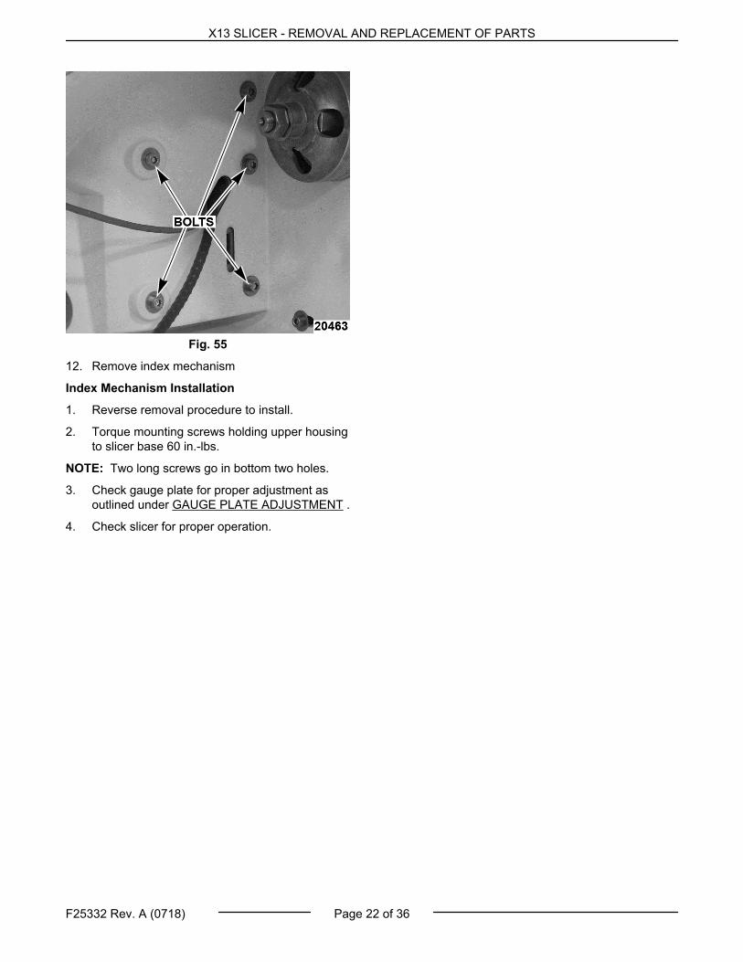
Fig. 55
12. Remove index mechanism
Index Mechanism Installation
1. Reverse removal procedure to install.
2. Torque mounting screws holding upper housingto slicer base 60 in.-lbs.
NOTE: Two long screws go in bottom two holes.
3. Check gauge plate for proper adjustment asoutlined under GAUGE PLATE ADJUSTMENT .
4. Check slicer for proper operation.
X13 SLICER - REMOVAL AND REPLACEMENT OF PARTS
F25332 Rev. A (0718) Page 22 of 36

SERVICE PROCEDURES AND ADJUSTMENTS
Certain procedures in this section require electrical test or measurements while power is applied to themachine. Exercise extreme caution at all times. If test points are not easily accessible, disconnect powerand follow lockout / tagout procedures, attach test equipment and reapply power to the test.
PRODUCT TABLE ADJUSTMENTS
Disconnect the electrical power tothe machine and follow lockout /tagout procedures.
1. Place slicer on its side, so it is resting on motorhousing.
2. Angle to knife.
A. Loosen mounting screw.
Fig. 56
B. Turn adjustment screw until product table isat a right angle with gauge plate.
NOTE: Adjustment screw raises/ lowers roller bearingabove square rail and nylon screw takes slack outbelow square rail.
Fig. 57
1) Tighten mounting screw.
3. Clearance with gauge plate.
A. Close gauge plate.
B. Check for 1/8" gap between guage plate andproduct table at "V" and leading edge.
Fig. 58
1) If out of adjustment, remove producttable and tighten or loosen tableadjusting screws accordingly.
X13 SLICER - SERVICE PROCEDURES AND ADJUSTMENTS
Page 23 of 36 F25332 Rev. A (0718)
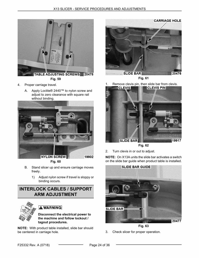
Fig. 59
4. Proper carriage travel.
A. Apply Loctite® 2440™ to nylon screw andadjust to zero clearance with square railwithout binding.
Fig. 60
B. Stand slicer up and ensure carriage movesfreely.
1) Adjust nylon screw if travel is sloppy orbinding occurs.
INTERLOCK CABLES / SUPPORTARM ADJUSTMENT
Disconnect the electrical power tothe machine and follow lockout /tagout procedures.
NOTE: With product table installed, slide bar shouldbe centered in carriage hole.
Fig. 61
1. Remove clevis pin, then slide bar from clevis.
Fig. 62
2. Turn clevis in or out to adjust.
NOTE: On X13A units the slide bar activates a switchon the slide bar guide when product table is installed.
Fig. 63
3. Check slicer for proper operation.
X13 SLICER - SERVICE PROCEDURES AND ADJUSTMENTS
F25332 Rev. A (0718) Page 24 of 36

INTERLOCK CABLES / INDEXKNOB ADJUSTMENTS
Disconnect the electrical power tothe machine and follow lockout /tagout procedures.
1. Insert cable into index knob.
A. Disconnect clevis pin and remove clevisfrom interlock slide bar.
Fig. 64
B. Remove INDEX KNOB.
C. Push cable until it stops.
D. Adjust gauge plate to knife height asoutlined under GAUGE PLATEADJUSTMENT.
E. Replace INDEX KNOB.
NOTE: Make sure end of cable goes into index knobhole within spiral groove.
Fig. 65
F. Torque nut to 140 in.-lbs.
2. Attach cable to slide rod.
A. Install product table as outlined underPRODUCT TABLE.
B. Pull clevis to retract cable from index knobuntil index knob turns freely.
C. Open index knob 1/4 turn and push cable inas far as it will go.
D. Turn clevis until hole aligns with hole ininterlock slide rod.
E. Turn clevis CW one full revolution.
F. Attach clevis to interlock slide rod with clevispin.
GAUGE PLATE ADJUSTMENT
Disconnect the electrical power tothe machine and follow lockout /tagout procedures.
The slicer knife is very sharp. Exercise extremecaution when working near the knife.
1. Gauge plate to knife gap.
A. Pull rubber boot away from adjustmentblock.
B. Loosen bolts and slide gauge plate intoposition.
Fig. 66
NOTE: Gauge plate to knife gap should be 1/8" atcenter of gauge plate. As knife wears, gap at top and
X13 SLICER - SERVICE PROCEDURES AND ADJUSTMENTS
Page 25 of 36 F25332 Rev. A (0718)

bottom of gauge plate will increase. Maintain 1/8" gapat center and an even gap top to bottom.
Fig. 67
C. Tighten bolts.
D. Place boot back into place and seal withRTV.
2. Gauge plate to knife angle.
A. Remove center plate and pull slide bartowards arm assembly to unlock index knob.
Fig. 68
B. Turn index knob until 3 contact points aremet at top of gauge plate.
Fig. 69
C. Pull rubber boot away from adjustmentblock.
D. Loosen top and bottom set screws.
NOTE: Bottom set screw is underneath adjustmentblock. (opposite top set screw)
Fig. 70
E. Loosen center bolt and adjust gauge plateso that bottom is 0.015" above top of gaugeplate.
F. Tighten bolt and set screws.
G. Recheck that gauge plate is still in properadjustment.
H. Place boot back into place and seal withRTV.
3. Gauge plate to knife height.
NOTE: Top of gauge plate should be 0.030" aboveknife when fully closed.
X13 SLICER - SERVICE PROCEDURES AND ADJUSTMENTS
F25332 Rev. A (0718) Page 26 of 36

Fig. 71
A. Fully close index knob.
B. Remove index knob cap and loosen nut oneand a half turns.
Fig. 72
C. Hold index knob at "0", and adjust index camup or down to achieve proper height.
Fig. 73
D. Hold index knob in place and tighten nut to140 in.-lbs.
E. Replace cap.
SHARPENING
Disconnect the electrical power tothe machine and follow lockout /tagout procedures.
1. Install sharpener as outlined underSHARPENER.
2. Open gauge plate all the way.
3. Push product tray toward knife until built-in stopin sharpener is actuated and hold for 5 seconds.
4. Bring product tray back to home position.
5. Check slicer for proper operation.
6. Repeat procedure if knife is not sharpened tosatisfaction.
CENTER PLATE CHECK
Disconnect the electrical power tothe machine and follow lockout /tagout procedures.
1. Check for even mark with straight edge as knifeis spinning at top, middle, and bottom of centerplate.
Fig. 74
2. If center plate needs adjustment, shim post studand shoulder studs.
X13 SLICER - SERVICE PROCEDURES AND ADJUSTMENTS
Page 27 of 36 F25332 Rev. A (0718)

Fig. 75
3. Apply Loctite® 2440™ to post stud after set.
AUTODRIVE ASSEMBLYADJUSTMENTS (X13A, X13AE)
Disconnect the electrical power tothe machine and follow lockout /tagout procedures.
Eccentric Pin AdjustmentNOTE: Eccentric pin is in adjustment when pullingclutch engage rod there is resistance during last 1/4to 1/8 of stroke. The resistance is the clip assemblygripping the primary belt.
1. Place primary belt in auto clip assembly.
Fig. 76
2. Remove screws and square rail.
Fig. 77
3. Loosen nut and adjust eccentric pin accordingly1/4 turn at a time.
Fig. 78
4. Tighten nut.
5. Recheck proper operation of clutch engage rod.
6. Install square rail.
7. Check slicer for proper operation.
WICK REPLACEMENT
Disconnect the electrical power tothe machine and follow lockout /tagout procedures.
1. Remove arm assembly as outlined under ARMASSEMBLY.
2. Remove round rail from transport arm.
3. Remove old wick from inside transport arm.
X13 SLICER - SERVICE PROCEDURES AND ADJUSTMENTS
F25332 Rev. A (0718) Page 28 of 36

Fig. 79
4. Coat new wick with Berkel oil and install intransport arm.
5. Reverse procedure to install.
6. Check slicer for proper operation.
SLIDE BAR SWITCH TEST (X13,X13A)
Certain procedures in this section requireelectrical test or measurements while power isapplied to the machine. Exercise extreme cautionat all times. If test points are not easily accessible,disconnect power and follow lockout / tagoutprocedures, attach test equipment and reapplypower to the test.
Certain components in this system are subject todamage by electrostatic discharge (ESD) during fieldrepairs. An ESD kit is required to prevent damage. TheESD kit must be used anytime the circuit board ishandled.
1. Remove product table as outlined underPRODUCT TABLE.
2. Place slicer on its side, so it is resting on motorhousing.
3. Remove screws to access control board.
Fig. 80
4. Plug slicer in.
5. Verify 5VDC between J4-1 and J4-5.
A. If voltage is not present, check allconnections.
B. If connections are good, replace controlboard.
6. Verify 5VDC between J4-4 and J4-5.
7. Supporting the arm assembly, squeeze the slidebar to the unlocked position and lower assembly.
Fig. 81
A. Verify 0VDC between J4-4 and J4-5anytime slide bar is squeezed into theunlocked position.
B. Verify 5VDC when slide bar is releasedagain.
8. If voltage is not present, replace slide bar switch.
X13 SLICER - SERVICE PROCEDURES AND ADJUSTMENTS
Page 29 of 36 F25332 Rev. A (0718)
CARRIAGE SENSOR TEST (X13,X13A)
Certain procedures in this section requireelectrical test or measurements while power isapplied to the machine. Exercise extreme cautionat all times. If test points are not easily accessible,disconnect power and follow lockout / tagoutprocedures, attach test equipment and reapplypower to the test.
1. Place slicer on its side, so it is resting on motorhousing.
2. Remove screws to access control board.
Fig. 82
3. Plug slicer in.
4. Verify 5VDC supply voltage between J4-1 andJ4-5.
A. If voltage is not present, check allconnections.
B. If connections are good, replace controlboard.
5. Verify 0VDC between J4-2 and J4-5 in manualmode (clutch engage rod in).
6. Verify 5VDC between J4-2 and J4-5 in auto mode(clutch engage rod out).
7. Verify 5VDC between J4-3 and J4-5 when armassembly is in home position.
A. 0VDC should be present anytime armassembly is away from home position.
8. If voltages are not all present, replace carriagesensor.
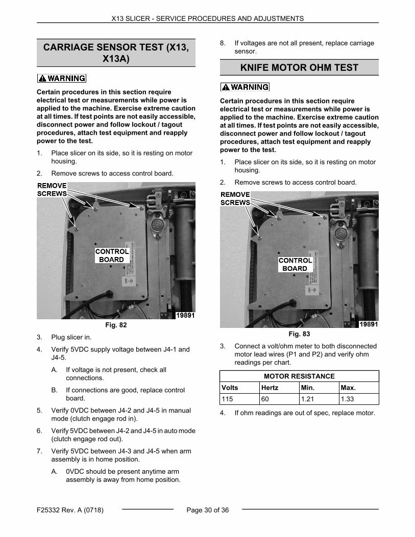
KNIFE MOTOR OHM TEST
Certain procedures in this section requireelectrical test or measurements while power isapplied to the machine. Exercise extreme cautionat all times. If test points are not easily accessible,disconnect power and follow lockout / tagoutprocedures, attach test equipment and reapplypower to the test.
1. Place slicer on its side, so it is resting on motorhousing.
2. Remove screws to access control board.
Fig. 83
3. Connect a volt/ohm meter to both disconnectedmotor lead wires (P1 and P2) and verify ohmreadings per chart.
MOTOR RESISTANCEVolts Hertz Min. Max.115 60 1.21 1.33
4. If ohm readings are out of spec, replace motor.
X13 SLICER - SERVICE PROCEDURES AND ADJUSTMENTS
F25332 Rev. A (0718) Page 30 of 36

CIRCUIT BREAKER TEST
Certain procedures in this section requireelectrical test or measurements while power isapplied to the machine. Exercise extreme cautionat all times. If test points are not easily accessible,disconnect power and follow lockout / tagoutprocedures, attach test equipment and reapplypower to the test.
1. Place slicer on its side, so it is resting on motorhousing.
2. Remove screws to access control board.
Fig. 84
3. Plug slicer in.
4. Verify 120VAC between J1-1(power cordneutral) and circuit breaker voltage in, circuitbreaker voltage out.
5. If voltage is not present at circuit breaker voltagein, replace the power cord.
6. If voltage is present at circuit breaker in but notout, replace circuit breaker.
X13 SLICER - SERVICE PROCEDURES AND ADJUSTMENTS
Page 31 of 36 F25332 Rev. A (0718)

ELECTRICAL OPERATION
COMPONENT FUNCTION
Keypad Assembly . . . . Controls electrical power to knife motor on all models and auto motor on automaticmodels.
Thermal Switch . . . . . . . Shuts down slicer if knife motor overheats.
Carriage Sensor(X13AE, X13A) . . . . . . . .
Detects when carriage is in home position and detects when auto mode has beenengaged.
Slide Bar Switch . . . . . . Detects when product table is installed/ removed.
Control Board . . . . . . . . Controls operation of all electrical components.
Circuit Board . . . . . . . . . Provides circuit protection for power supply.
Automatic Motor(X13A, X13AE) . . . . . . . .
Drives automatic slicing mechanism.
Timer Assemblyoptional) . . . . . . . . . . . . . .
Provides auto shutoff feature if no slicing for 15 seconds.
ERROR CODE TEST
1. Error codes are designated by the number of times the red pilot light on the keypad flashes. To reset, push
the STOP button.
No. of
Flashes Problem Probable Cause
1 High temperature detected on control board. Replace control board.
2 Over current detected in control board. DC motor shorted or control board malfunction: Replaceboth control board and DC motor.
3 Knife motor over temperature. Check for malfunctioning knife motor.
4 Auto motor internal hall effect malfunction. Replace DC motor.
5 Auto motor internal hall effect transitionmalfunction. Replace DC motor.
6 Encoder input not active. Replace DC motor.
7 Unable to find home. Malfunctioning carriage switch, or malfunctioning plate flexcable, or no magnet in base.
8 Carriage moving too fast or slow. Check J9 cable, or check flex cable, or clean round rail.
9 Clutch disengaged while running. Re-engage auto or adjust eccentric pin.
10 Slide bar guide switch not engaged. Check or adjust slide bar guide switch.
WIRING DIAGRAMS WITHSEQUENCE OF OPERATIONS
X13 & X13E Sequence of Operation
X13 SLICER - ELECTRICAL OPERATION
F25332 Rev. A (0718) Page 32 of 36

X13 & X13E Wiring DiagramNOTE: Knife can be started with carriage in anyposition.
Start Conditions:
1. Correct voltage supplied to slicer.
2. Red power LED lit.
3. Carriage tray secured.
Manual Sequence:
1. Press start button - start switch closed.
2. 15VDC is applied to control board.
3. Knife motor energized.
4. Knife motor continues to run until stop button ispressed.
NOTE: Slicers equipped with timer assembly will shutoff after 15 seconds of no slicing.
5. Press stop button - stop switch opens.
6. 15VDC is removed from control board.
7. Knife motor de-energized.
X13A & X13AE Sequence of Operation
X13 SLICER - ELECTRICAL OPERATION
Page 33 of 36 F25332 Rev. A (0718)

X13A & X13AE Wiring DiagramNotes:
1. Knife can be started with carriage in any position.
2. Slicer cannot be switched from manual operationto automatic with knife motor energized.
A. When auto engage lever is engaged withknife motor running, hall effect switch willsignal control board to de-energize knifemotor.
Start Conditions:
1. Correct voltage supplied to slicer.
2. Red power LED lit.
3. Carriage tray secured.
A. (X13A only) Slide bar switch closed; controlboard signaled that carriage is in place.
Manual Sequence:
1. Press start button - start switch closed.
2. 15VDC is applied to control board.
3. Knife motor energized.
4. Knife motor continues to run until stop button ispressed.
NOTE: Slicers equipped with timer assembly will shutoff after 15 seconds of no slicing.
5. Press stop button - stop switch opens.
6. 15VDC is removed from control board.
7. Knife motor de-energized.
Automatic Sequence:
1. Conditions:
X13 SLICER - ELECTRICAL OPERATION
F25332 Rev. A (0718) Page 34 of 36

A. Correct voltage supplied to slicer.
B. Red power LED lit.
C. Carriage tray secured.
1) (X13A only) Slide bar switch closed;control board signaled that carriage isin place.
D. Auto engage lever pulled out into engagedposition.
1) Hall effect switch signals board thatauto mode has been selected.
NOTE: Default settings are slow speed and fullstroke. However slicer will remember last settingsunless power has been removed from the slicer.
2. Select speed - LED will indicate selection.
3. Select stroke length - LED will indicate selection.
4. Press start button - start switch closed.
5. 15VDC is applied to control board.
6. Knife motor energized.
A. Knife motor continues to run until stopbutton is pressed.
NOTE: Slicers equipped with timer assembly will shutoff after 15 seconds of no slicing.
7. Auto motor energized.
A. Motor finds home position.
1) Hall effect switch is positioned undermagnet and control board is signaled.
B. Carriage begins to move at selected speedand stroke.
8. Press stop button - stop switch opens.
9. 15VDC is removed from control board.
10. Knife motor de-energized.
11. Auto motor de-energized after returning to home.
X13 SLICER - ELECTRICAL OPERATION
Page 35 of 36 F25332 Rev. A (0718)

TROUBLESHOOTING
TROUBLESHOOTING TABLE
SYMPTOM POSSIBLE CAUSE
Knife motor will not start.
1. No power to slicer.
2. Keypad malfunction.
3. Thermal switch open.
4. Motor malfunction.
Slicer will not shut off.1. Keypad malfunction.
2. Control board malfunction.
Hard to slice.
1. Dull knife.
2. Adjustment screw binding on square rail.
3. Oil wick not properly lubricated.
Wedged shaped slices.1. Gauge plate not properly adjusted.
2. Product not stable in product table.
Noisy.
1. Bearing malfunction.
2. Oil wick not properly lubricated.
3. Motor malfunction.
4. Belt mis-aligned.
Noisy in automatic mode.
1. Belts not properly tensioned.
2. Belts worn.
3. Auto motor malfunction.
Knife motor running, knife not turning.1. Knife belt malfunction.
2. Knife hub assembly malfunction.
Knife running or starting at less thanrated RPM (slow).
1. Motor malfunction.
2. Drive belt malfunction.
3. Bearing malfunction.
Automatic slicing not engaging.
1. Product table not properly seated.
2. Flex cable damaged/ disconnected.
3. Slide bar switch out of adjustment/ malfunction.
4. Carriage sensor malfunction.
5. Magnet on auto clip arm misaligned.
6. Auto belt malfunction.
7. Keypad malfunction.
8. Control board malfunction.
9. Auto motor malfunction.
X13 SLICER - TROUBLESHOOTING
F25332 Rev. A (0718) Page 36 of 36