Embed Size (px)
Citation preview

SERVICE MANUAL T3.2
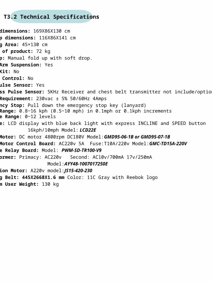
Setup dimensions: 169X86X130 cm
Fold Up dimensions: 116X86X141 cm
Running Area: 45×130 cm
Weight of product: 72 kg
Fold Up: Manual fold up with soft drop.
Swing Arm Suspension: Yes
Music Kit: No
Motion Control: No
Hand Pulse Sensor: Yes
Wireless Pulse Sensor: 5KHz Receiver and chest belt transmitter not include/optional
Power Requirement: 230vac ± 5% 50/60Hz 4Amps
Emergency Stop: Pull down the emergency stop key (lanyard)Speed Range: 0.8~16 kph (0.5~10 mph) in 0.1mph or 0.1kph increments Incline Range: 0~12 levels
Console: LCD display with blue back light with express INCLINE and SPEED button
16kph/10mph Model: LCD22E
Drive Motor: DC motor 4800rpm DC180V Model:GMD95-06-1B or GMD95-07-1B
Drive Motor Control Board: AC220v 5A Fuse:T10A/220v Model:GMC-TD15A-220V
Incline Relay Board: Model: PWM-SD-TR100-V9
Transformer: Primacy: AC220v Second: AC10v/700mA 17v/250mA
Model:AYY48-1007017250E
Elevation Motor: A220v model:JS15-420-230
Running Belt: 445X2668X1.6 mm Color: 11C Gray with Reebok logo
Maximum User Weight: 130 kg
T3.2 Technical Specifications
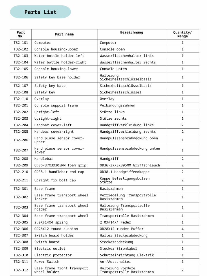
Parts List
Part No. Part name Bezeichnung Quantity/Menge
T32-101 Computer Computer 1
T32-102 Console housing-upper Console oben 1
T32-103 Water bottle holder-left Wasserflaschenhalter links 1
T32-104 Water bottle holder-right Wasserflaschenhalter rechts 1
T32-105 Console housing-lower Console unten 1
T32-106 Safety key base holder Halterung Sicherheitsschlüsselbasis 1
T32-107 Safety key base Sicherheitsschlüsselbasis 1
T32-108 Safety key Sicherheitsschlüssel 1
T32-110 Overlay Overlay 1
T32-201 Console support frame Verbindungsrahmen 1
T32-202 Upright-left Stütze links 1
T32-203 Upright-right Stütze rechts 1
T32-204 Handbar cover-left Handgriffverkleidung links 2
T32-205 Handbar cover-right Handgriffverkleidung rechts 2
T32-206 Hand pluse sensor cover-upper Handpulssensorabdeckung oben 1
T32-207 Hand pluse sensor cover-lower Handpulssensorabdeckung unten 1
T32-208 Handlebar Handgriff 2
T32-209 OD36-37X3X305MM foam grip OD36-37X3X305MM Griffschlauch 2
T32-210 OD38.1 handlebar end cap OD38.1 Handgriffendkappe 2
T32-211 Upright fix bolt cap Kappe Befestigungsbolzen Stütze 2
T32-301 Base frame Basisrahmen 1
T32-302 Base frame transport wheel locker Verriegelung Transportrolle Basisrahmen 1
T32-303 Base frame transport wheel holder Halterung Transportrolle Basisrahmen 1
T32-304 Base frame transport wheel Transportrolle Basisrahmen 1
T32-305 2.0X∮14X4 spring 2.0X∮14X4 Feder 1
T32-306 OD28X12 round cushion OD28X12 runder Puffer 4
T32-307 Switch board holder Halter Steckerabdeckung 1
T32-308 Switch board Steckerabdeckung 1
T32-309 Electric outlet Stecker Stromkabel 1
T32-310 Electric protector Schutzeinrichtung Elektrik 1
T32-311 Power Switch An-/Ausschalter 1
T32-312 Base frame front transport wheel holder
Halterung vordere Transportrolle Basisrahmen 2
T32-313 ID19XOD66X24 transport wheel ID19XOD66X24 Transportrolle 2
T32-314 25X28X30 elliptical tube cushion 25X28X30 runder Rohrpuffer 2
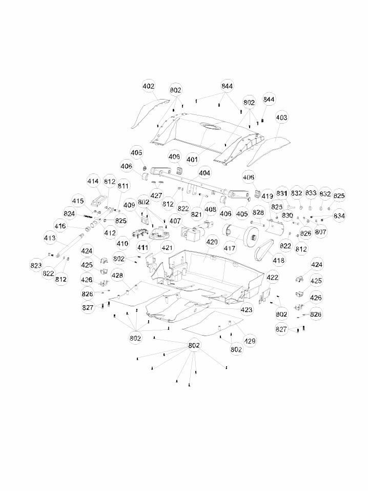
T32-401 Motor hood Motorabdeckung 1
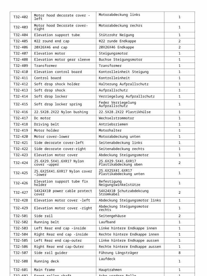
T32-402 Motor hood decorate cover -leftMotorabdeckung links
1
T32-403 Motor hood Decorate cover-right Motorabdeckung rechrs 1
T32-404 Elevation support tube Stützrohr Neigung 1
T32-405 Φ22 round end cap Φ22 runde Endkappe 2
T32-406 20X26X46 end cap 20X26X46 Endkappe 2
T32-407 Elevation motor Steigungsmotor 1
T32-408 Elevation motor gear sleeve Buchse Steigungsmotor 1
T32-409 Transformer Transformer 1
T32-410 Elevation control board Kontrolleinheit Steigung 1
T32-411 Control board Kontrolleinheit 1
T32-412 Soft drop shock holder Halterung Aufprallschutz 1
T32-413 Soft drop shock Aufprallschutz 1
T32-414 Soft drop locker Verriegelung Aufprallschutz 1
T32-415 Soft drop locker spring Feder Verriegelung Aufprallschutz 1
T32-416 22.5X28.2X22 Nylon bushing 22.5X28.2X22 Plastikhülse 1
T32-417 Dc motor Wechselstrommotor 1
T32-418 Driving belt Antriebsriemen 1
T32-419 Motor holder Motorhalter 1
T32-420 Motor cover-lower Motorabdeckung unten 1
T32-421 Side decorate cover-left Seitenabdeckung links 1
T32-422 Side decorate cover-right Seitenabdeckung rechts 1
T32-423 Elevation motor cover Abdeckung Steigungsmotor 1
T32-424 25.6X29.5X41.6XR17 Nylon cover -upper
25.6X29.5X41.6XR17 Plastikabdeckung oben 2
T32-425 25.6X25X41.6XR17 Nylon cover –lower
25.6X25X41.6XR17 Plastikabdeckung unten 1
T32-426 Elevation support tube fix holder Befestigung Neigungswinkelstütze 1
T32-427 54X24X10 power cable protect cover54X24X10 Schutzabdekcung Stromkabel 2
T32-428 Elevation motor cover -left Abdeckung Steigungsmotor links 1
T32-429 Elevation motor cover -right Abdeckung Steigungsmotor rechts 1
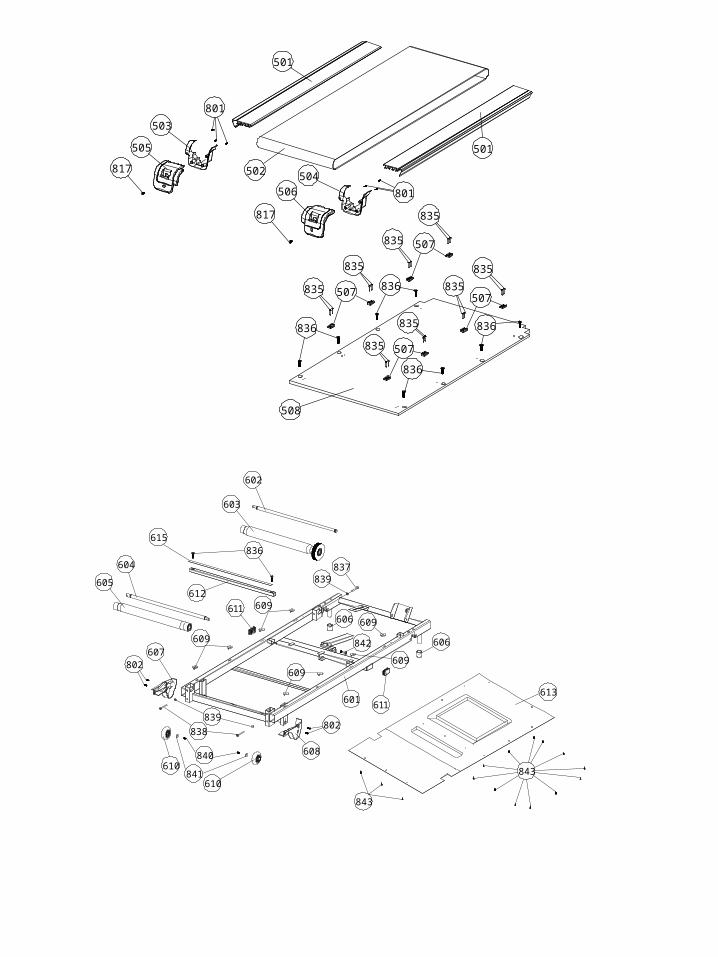
T32-501 Side rail Seitengehäuse 2
T32-502 Running belt Laufband 1
T32-503 Left Rear end cap –inside Linke hintere Endkappe innen 1
T32-504 Right Rear end cap -inside Rechte hintere Endkappe innen 1
T32-505 Left Rear end cap-outer Linke hintere Endkappe aussen 1
T32-506 Right Rear end cap-Outer Rechte hintere Endkappe aussen 1
T32-507 Side rail guider Führung Längsträger 8
T32-508 Running deckLaufdeck
1
T32-601 Main frame Hauptrahmen 1
T32-602 Front roller shaft Ache vordere Rolle 1
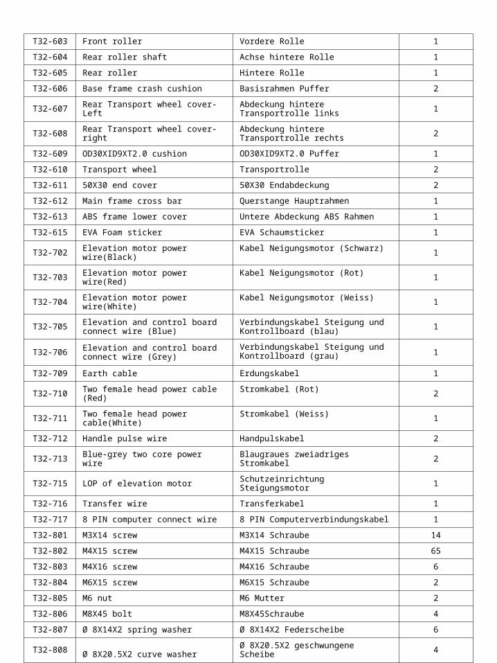
T32-603 Front roller Vordere Rolle 1
T32-604 Rear roller shaft Achse hintere Rolle 1
T32-605 Rear roller Hintere Rolle 1
T32-606 Base frame crash cushion Basisrahmen Puffer 2
T32-607 Rear Transport wheel cover-Left Abdeckung hintere Transportrolle links 1
T32-608 Rear Transport wheel cover-right Abdeckung hintere Transportrolle rechts 2
T32-609 OD30XID9XT2.0 cushion OD30XID9XT2.0 Puffer 1
T32-610 Transport wheel Transportrolle 2
T32-611 50X30 end cover 50X30 Endabdeckung 2
T32-612 Main frame cross bar Querstange Hauptrahmen 1
T32-613 ABS frame lower cover Untere Abdeckung ABS Rahmen 1
T32-615 EVA Foam sticker EVA Schaumsticker 1
T32-702 Elevation motor power wire(Black) Kabel Neigungsmotor (Schwarz) 1
T32-703 Elevation motor power wire(Red) Kabel Neigungsmotor (Rot) 1
T32-704 Elevation motor power wire(White) Kabel Neigungsmotor (Weiss) 1
T32-705 Elevation and control board connect wire (Blue)
Verbindungskabel Steigung und Kontrollboard (blau) 1
T32-706 Elevation and control board connect wire (Grey)
Verbindungskabel Steigung und Kontrollboard (grau) 1
T32-709 Earth cable Erdungskabel 1
T32-710 Two female head power cable (Red) Stromkabel (Rot) 2
T32-711 Two female head power cable(White) Stromkabel (Weiss) 1
T32-712 Handle pulse wire Handpulskabel 2
T32-713 Blue-grey two core power wire Blaugraues zweiadriges Stromkabel 2
T32-715 LOP of elevation motor Schutzeinrichtung Steigungsmotor 1
T32-716 Transfer wire Transferkabel 1
T32-717 8 PIN computer connect wire 8 PIN Computerverbindungskabel 1
T32-801 M3X14 screw M3X14 Schraube 14
T32-802 M4X15 screw M4X15 Schraube 65
T32-803 M4X16 screw M4X16 Schraube 6
T32-804 M6X15 screw M6X15 Schraube 2
T32-805 M6 nut M6 Mutter 2
T32-806 M8X45 bolt M8X45Schraube 4
T32-807 Ø 8X14X2 spring washer Ø 8X14X2 Federscheibe 6
T32-808 Ø 8X20.5X2 curve washer Ø 8X20.5X2 geschwungene Scheibe 4
T32-809 M8X30 Allen bolt M8X30 Sechskantschraube 2
T32-810 M8X18 allen Bolt M8X18 Sechskantschraube 2
T32-811 M10X40 allen bolt M10X40 Sechskantschraube 3
T32-812 M10 Nylon nut M10 Plastikmutter 7

T32-813 ∮8X36 transport axle ∮8X36 Transportachse 1
T32-814 M8-C cliper M8-C Clipper 1
T32-815 ∮6X11.5 fixed bolt ∮6X11.5 Befestigungsbolzen 2
T32-816 M6-C cliper M6-C Clipper 2
T32-817 M5X14 screw M5X14 Schraube 6
T32-818 M10X53 allen bolt M10X53 Sechskantschraube 1
T32-819 M3X8 screw M3X8 Schraube 2
T32-820 M4.2X14 screw M4.2X14 Schraube 4
T32-821 M10X67 allen bolt M10X67 Sechskantschraube 1
T32-822 10.5X20X2 washer 10.5X20X2 Scheibe 3
T32-823 M10X33 allen bolt M10X33 Sechskantschraube 1
T32-824 M8X65 allen bolt M8X65 Sechskantschraube 1
T32-825 M8 Nylon nut M8 Plastikmutter 3
T32-826 Ø 8.5X16.5X1.5 washer Ø 8.5X16.5X1.5 Scheibe 6
T32-827 M8X20 allen screw M8X20 Sechskantschraube 4
T32-828 M10X115 Bolt M10X115 Schraube 1
T32-829 M16X80 Bolt M16X80 Schraube 2
T32-830 M8X48 Bolt M8X48 Schraube 1
T32-831 M8X85X20 motor holder fix BoltM8X85X20 Befestigungsschraube Motorhalterung
1
T32-832 Ø 9X35X8 curve washer Ø 9X35X8 geschwungene Scheibe 2
T32-833 8X26X11 PU CUSHION 8X26X11 Plastikpuffer 1
T32-834 M8X14-Screw M8X14-Schraube 2
T32-835 M4X19 Screw M4X19 Schraube 16
T32-836 M8X30 Screw M8X30 Schraube 10
T32-837 M6X65 allen screw M6X65 Sechskantschraube 1
T32-838 M6X55 allen screw M6X55 Sechskantschraube 2
T32-839 M6.5X12.6X1.25 screw M6.5X12.6X1.25 Schraube 3
T32-840 M6X10 screw M6X10 Schraube 2
T32-841 Ø 6.4X18X1.5 washer Ø 6.4X18X1.5 Scheibe 2
T32-842 M10X32 cap head bolt M10X32 Kopfschraube 1
T32-843 M4X12 Screw M4X12 Schraube 15
T32-844 Plastic insert Plastikdübel 4
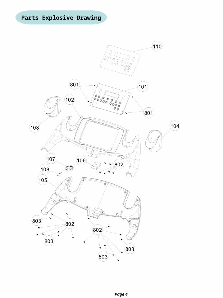
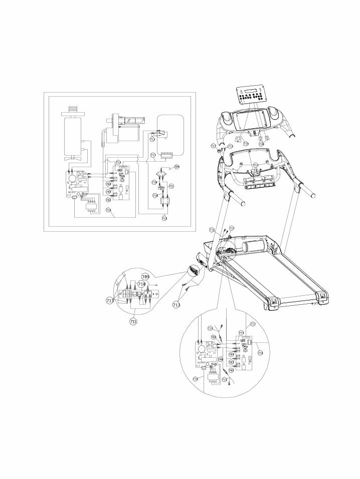
Parts Explosive Drawing
Page 4
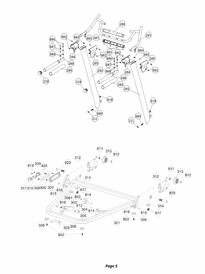
Page 5
806
807
808
808
807
806
802 804 805
801 802802
804805
205
802202
201
206
207
204
205
204
208
209210
208
209
210
810
809809
211211
810
203
835
835
835
835
507
507
835
835
835
835
507
507
817
505
503
817
506
504502
501
501
836
836
836
836
801
801
508
836
602
603
604
605
837839
606
606
601
802
608840
841
839
838
610
610
802607
842
611
611
612
609
609
609
609
609
613
843
843
615
711
710
709
713713
713
717
718
713
716
715
711
710
710
709
703
702
704
COM
+
717
716
716
713
706
713
705
ELE VR
704
702
703
715
110V
717
713717
712
720719
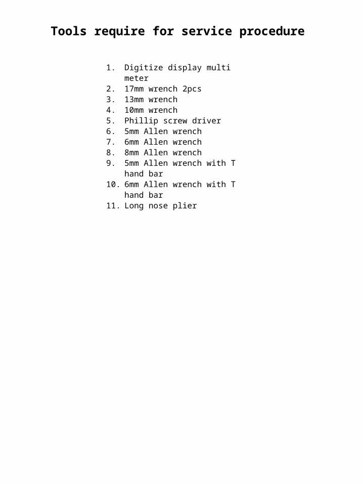
Tools require for service procedure
1. Digitize display multi meter2. 17mm wrench 2pcs3. 13mm wrench4. 10mm wrench5. Phillip screw driver6. 5mm Allen wrench7. 6mm Allen wrench8. 8mm Allen wrench9. 5mm Allen wrench with T
hand bar10. 6mm Allen wrench with T hand
bar11. Long nose plier
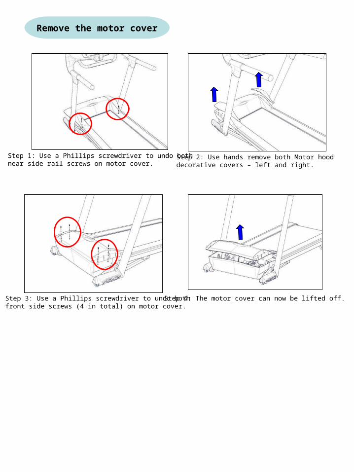
Remove the motor cover
Step 1: Use a Phillips screwdriver to undo bothnear side rail screws on motor cover.
Step 2: Use hands remove both Motor hood decorative covers – left and right.
Step 3: Use a Phillips screwdriver to undo bothfront side screws (4 in total) on motor cover.
Step 4: The motor cover can now be lifted off.
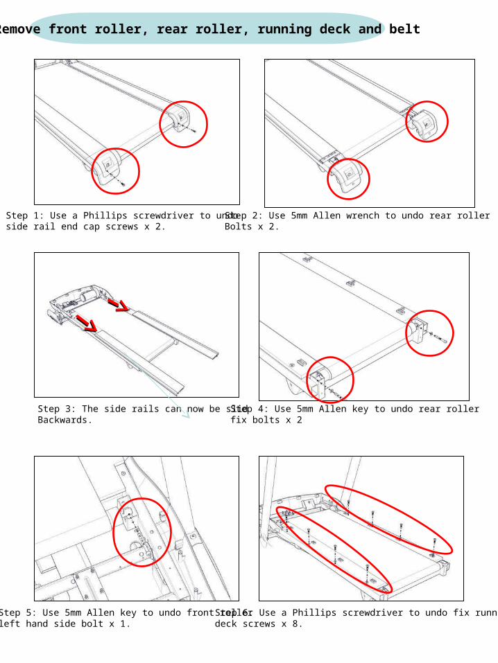
Step 1: Use a Phillips screwdriver to undoside rail end cap screws x 2.
Step 2: Use 5mm Allen wrench to undo rear rollerBolts x 2.
Step 3: The side rails can now be slid Backwards.
Step 4: Use 5mm Allen key to undo rear rollerfix bolts x 2
Step 5: Use 5mm Allen key to undo front rollerleft hand side bolt x 1.
Step 6: Use a Phillips screwdriver to undo fix runningdeck screws x 8.
Remove front roller, rear roller, running deck and belt
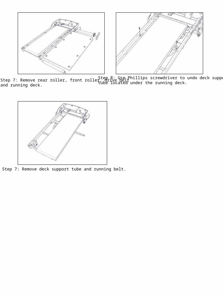
Step 7: Remove rear roller, front roller, drive beltand running deck.
Step 8: Use Phillips screwdriver to undo deck supporttube located under the running deck.
Step 7: Remove deck support tube and running belt.
Page 10
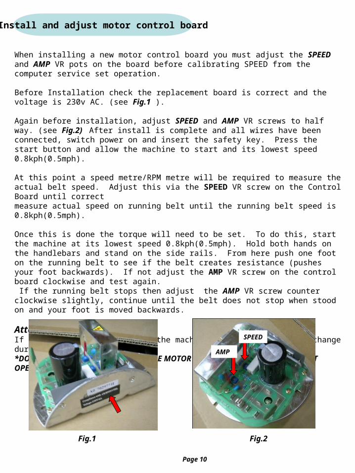
Install and adjust motor control board
When installing a new motor control board you must adjust the SPEED and AMP VR pots on the board before calibrating SPEED from the computer service set operation.
Before Installation check the replacement board is correct and the voltage is 230v AC. (see Fig.1 ).
Again before installation, adjust SPEED and AMP VR screws to half way. (see Fig.2) After install is complete and all wires have been connected, switch power on and insert the safety key. Press the start button and allow the machine to start and its lowest speed 0.8kph(0.5mph).
At this point a speed metre/RPM metre will be required to measure the actual belt speed. Adjust this via the SPEED VR screw on the Control Board until correctmeasure actual speed on running belt until the running belt speed is 0.8kph(0.5mph).
Once this is done the torque will need to be set. To do this, start the machine at its lowest speed 0.8kph(0.5mph). Hold both hands on the handlebars and stand on the side rails. From here push one foot on the running belt to see if the belt creates resistance (pushes your foot backwards). If not adjust the AMP VR screw on the control board clockwise and test again. If the running belt stops then adjust the AMP VR screw counter clockwise slightly, continue until the belt does not stop when stood on and your foot is moved backwards.
Attention:If the AMP VR is set too high the machines speed will suddenly change during use,*DO NOT ADJUST THIS TOO HIGH AS THE MOTOR WILL BE AFFECTED AND WILL NOT OPERATE CORRECTLY*
SPEED
AMP
Fig.1 Fig.2

Install and adjust elevation motor
Before installing a new elevation motor first confirm voltage and model are correct from theelevation motor lable.(see Fig.1).
When installing a new elevation motor, firstly only fix the new elevation motor rear body onto theMain frame and connect all wires onto the incline relay board. (see Fig.2). Next switchtreadmill power on, insert safety key then press START button, elevation motor will automaticallyturn to level “0” position.
Follow service set calibration incline instruction, while calibration incline level “0” then directpress INCLINE DOWN button continuous still elevation motor turning stop. Next switch treadmill power off.
Take elevation nut tube to turn in elevation spiral bar, (see Fig.3) still nut tube end frame bolthole to aim at elevation swing arm frame hole. Then insert the long bolt and use 17mm wrenchTo fix nut. (see Fig.4).
After complete elevation motor install follow service set instructions to calibrate incline.When calibrating incline level “0”, the distance must be 10~15mm from the circular rubber bufferto running deck main frame, and when calibration level “15” just pull up elevation nut tube to edge,(see Fig.5). Do not let elevation nut tube raech the elevation motor body end position. (see Fig.6).
Fig.1 Fig.2 Fig.3
Fig.4 Fig.5 Fig.6Page 11
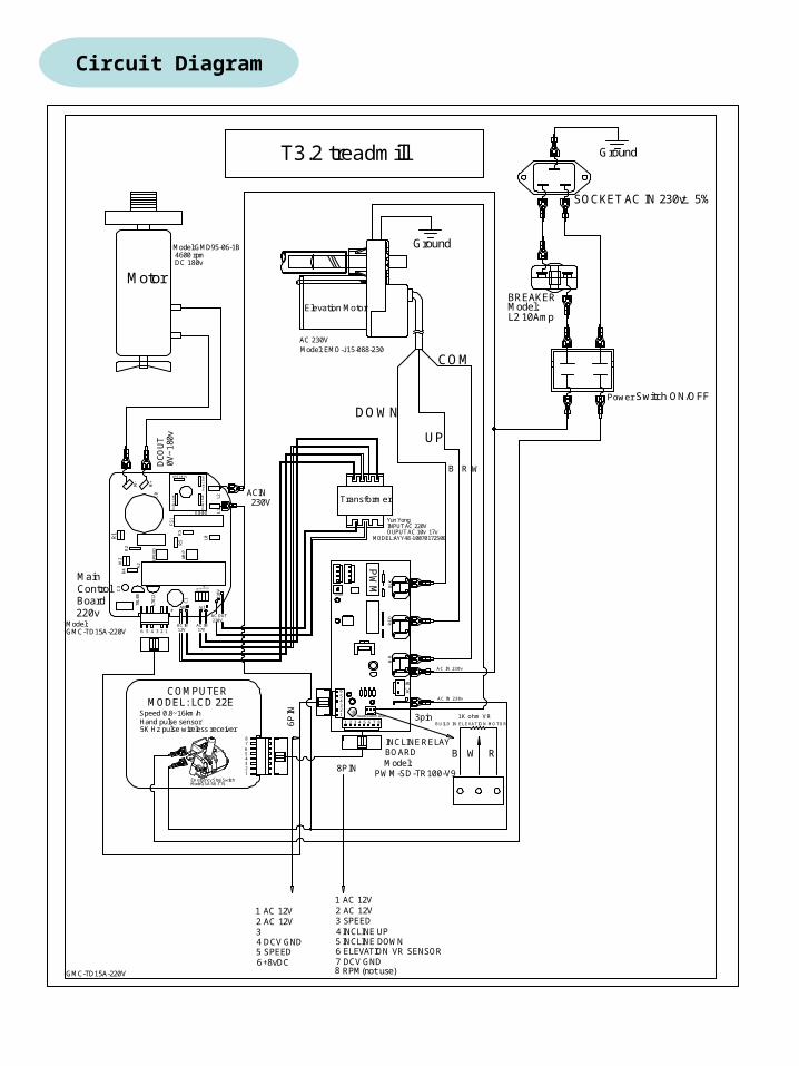
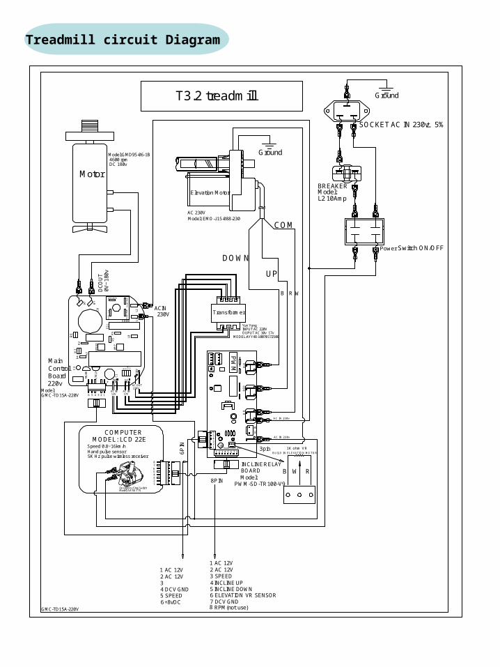
Circuit Diagram
RE
D
6P
IN
WH
AC
IN
8PIN
M-
ho
le1
.6x
8
M+
C1
L781
2
17V10V
+
SP
EE
D
AM
P
C0
ho
le1
.6x8
D0-D3
R5
R5
FS
1h
ole
1.6
x8
D1
0
D8
D9
L1
L211
0VD
11L0
W2
R1
R2
C3
R4
78L
08A
2
hole1.6x8
Elevationmotor VR sensor 3pin
B R W
Motor
Board220v
ControlMain
COMPUTERMODEL: LCD 22E
SOCKET AC IN 230v 5%
Power Switch ON/OFF
BREAKERModel:Elevation Motor
3 SPEED
INCLINERELAYBOARD
DC
OU
T0V
~18
0v
5 4 3 2 1
8
654321
1 AC 12V2 AC 12V
5 INCLINE DOWN4 INCLINE UP
1 2 3 4 5 6 7
54321
AC OUT220V
AC IN12V
AC IN17V
ACIN230V
VR10K
BL
K
Transformer
B W R
1K ohm VRB UILD IN ELEVATIO N MO TOR
UP
Ground
DCV GND4SPEED5
AC 12V2AC 12V1
3
ELEVATION VR SENSOR6DCV GND7
7
6
8
6
8 RPM(not use)
AC IN 230v
6+8vDC
T3.2 treadmill
Model: EMO-J15-088-230
Yun YongINPUT AC 220V
+ ~~ GW
W06M
PW
M
AC IN 230v
Model:GMD95-06-1B4600 rpmDC 180v
+_
DOWN
COM
OUPUT AC 10v 17v
Ground
L2 10Amp
5K Hz pulse wireless receiver
Speed 0.8~16km/hHand pulse sensor
GMC-TD15A-220V
GMC-TD15A-220V
Model:
MODEL:AYY48-1007017250E
Model:PWM-SD-TR100-V9
AC 230V
Emergency Stop SwitchModel: SA-SK-T75
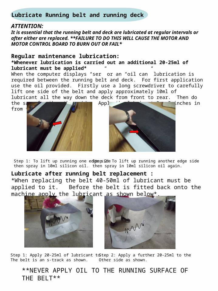
Lubricate Running belt and running deck
ATTENTION:It is essential that the running belt and deck are lubricated at regular intervals or after either are replaced. **FAILURE TO DO THIS WILL CAUSE THE MOTOR AND MOTOR CONTROL BOARD TO BURN OUT OR FAIL*
Regular maintenance lubrication:*Whenever lubrication is carried out an additional 20-25ml of lubricant must be applied*When the computer displays “ser” or an “oil can” lubrication is required between the running belt and deck. For first application use the oil provided. Firstly use a long screwdriver to carefully lift one side of the belt and apply approximately 10ml of lubricant all the way down the deck from front to rear. Then do the same for the other side. Apply the lubricant 2 – 3 inches in from the side of the belt.
Step 1: To lift up running one edge sidethen spray in 10ml silicon oil.
Step 2: To lift up running another edge sidethen spray in 10ml silicon oil again.
Lubricate after running belt replacement :*When replacing the belt 40-50ml of lubricant must be applied to it. Before the belt is fitted back onto the machine apply the lubricant as shown below*.
Step 1: Apply 20-25ml of lubricant toThe belt is an s-track as shown.
Step 2: Apply a further 20-25ml to the Other side as shown.
**NEVER APPLY OIL TO THE RUNNING SURFACE OF THE BELT**
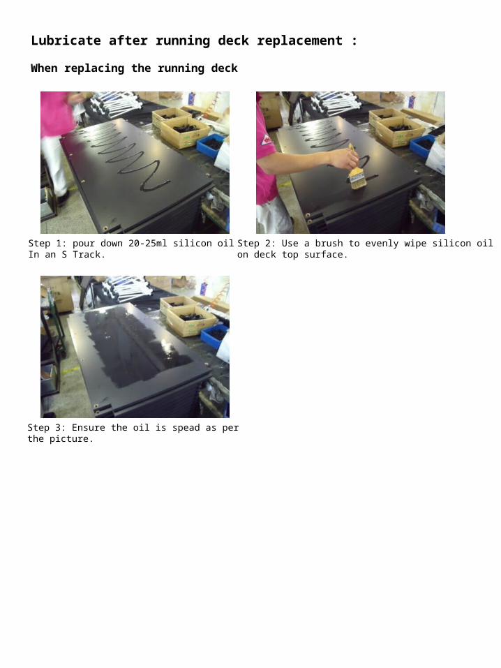
Lubricate after running deck replacement :
When replacing the running deck
Step 1: pour down 20-25ml silicon oil In an S Track.
Step 2: Use a brush to evenly wipe silicon oilon deck top surface.
Step 3: Ensure the oil is spead as per the picture.
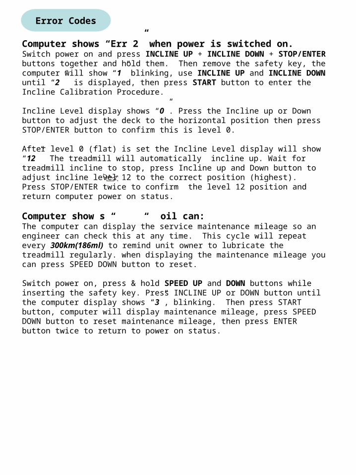
Error Codes
Computer shows “Err 2” when power is switched on.Switch power on and press INCLINE UP + INCLINE DOWN + STOP/ENTER buttons together and hold them. Then remove the safety key, the computer will show “1” blinking, use INCLINE UP and INCLINE DOWN until “2” is displayed, then press START button to enter the Incline Calibration Procedure.
Incline Level display shows “0”. Press the Incline up or Down button to adjust the deck to the horizontal position then press STOP/ENTER button to confirm this is level 0.
After level 0 (flat) is set the Incline Level display will show “12” The treadmill will automatically incline up. Wait for treadmill incline to stop, press Incline up and Down button to adjust incline level 12 to the correct position (highest). Press STOP/ENTER twice to confirm the level 12 position and return computer power on status.
Computer show s “ “ oil can: The computer can display the service maintenance mileage so an engineer can check this at any time. This cycle will repeat every 300km(186ml) to remind unit owner to lubricate the treadmill regularly. when displaying the maintenance mileage you can press SPEED DOWN button to reset.
Switch power on, press & hold SPEED UP and DOWN buttons while inserting the safety key. Press INCLINE UP or DOWN button until the computer display shows “3”, blinking. Then press START button, computer will display maintenance mileage, press SPEED DOWN button to reset maintenance mileage, then press ENTER button twice to return to power on status.

Enter the service Engineer ModeSwitch the power on, press and hold INCLINE UP, DOWN and STOP/ENTER buttons together and hold them, then insert the safety key to enter the ENGINEER MODE. The Time/Distance display shows “1” blinking.
Set and display, manufacture date and software versionPress START button, Time/Distance display shows the manufacture YEAR, Heart Rate display shows manufacture MONTH, Calories display shows manufacture DATE. Speed display shows software version. The service engineer can adjust the manufacture date by pressing Incline Up or Down buttons, follow the blinking display then press STOP/ENTER button after each adjustment to record the service date if necessary. After all the adjustment is done, press STOP/ENTER button again to exit the Engineer Mode.
Incline CalibrationEnter Engineer mode (as above)Press INCLINE UP or DOWN button until the computer display shows “2” then press START button to enter the Incline Calibration Procedure.
Incline Level display shows “0”. Press INCLINE UP or DOWN button to bring the deck to horizontal position then press STOP/ENTER button to set the L0 level.
After level 0 is set, Incline Level display shows “12”. The treadmill will automatically incline up. Wait for treadmill incline to stop, press INCLINE UP or DOWN button to adjust incline L12 to the correct position , then press STOP/ENTER twice to set the L12 level and exit the engineer mode.
Speed CalibrationEnter Engineer mode (as above)Press INCLINE UP or DOWN button until the computer display shows “3” then press START button to enter the Speed Calibration Procedure.
Speed display shows “0.5”mph or “0.8”kph. Press SPEED UP or DOWN button to adjust the actual speed and measure the belt speed using a speed meter then press STOP/ENTER button to set the lowest speed.
After setting the lowest speed, the speed display shows “10”mph or “16”kph and the treadmill speed will start increase. Wait until the treadmill stop increasing speed, measure the belt speed using a speed meter and press SPEED UP or DOWN to adjust the actual speed then press STOP/ENTER button twice to exit the Engineer mode and save the settings.
Engineer mode Setting
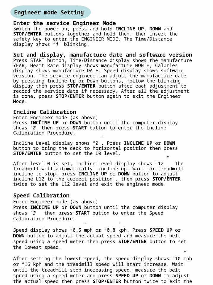
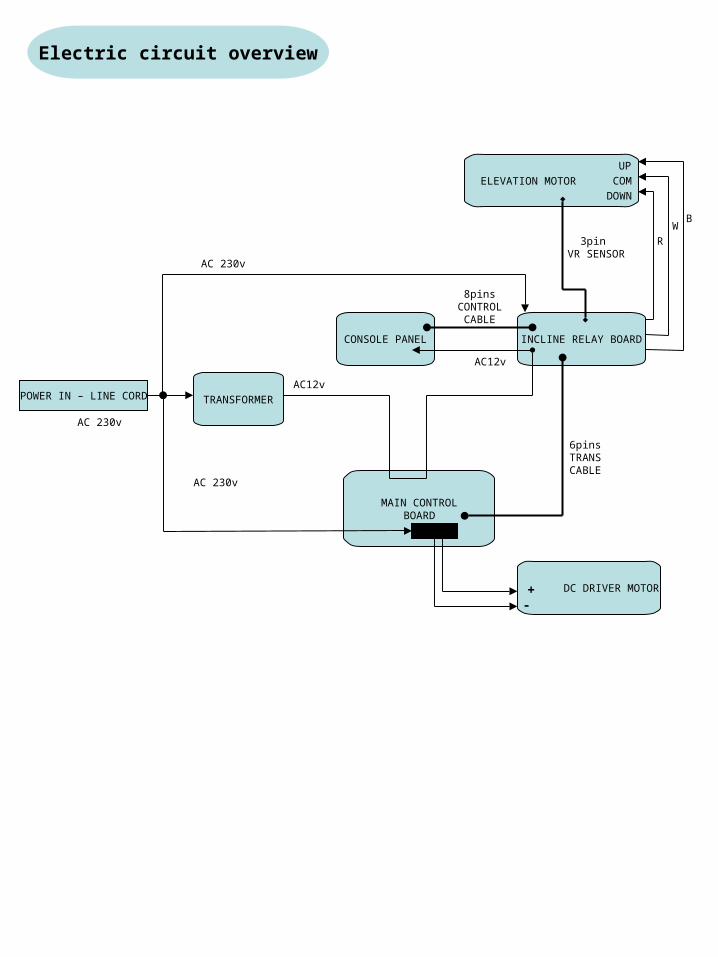
CONSOLE PANEL
POWER IN – LINE CORD
MAIN CONTROLBOARD
DC DRIVER MOTOR
AC 230v
TRANSFORMER
AC12v
8pins CONTROL
CABLE
INCLINE RELAY BOARD
ELEVATION MOTOR
AC 230v
AC 230v
3pin VR SENSOR
WB
R
+-
6pins TRANS CABLE
AC12v
UP
DOWN
COM
Electric circuit overview
Treadmill circuit Diagram
RE
D
6P
IN
WH
AC
IN
8PIN
M-
ho
le1
.6x
8
M+
C1
L781
2
17V10V
+
SP
EE
D
AM
P
C0
ho
le1
.6x8
D0-D3
R5
R5
FS
1h
ole
1.6
x8
D1
0
D8
D9
L1
L211
0VD
11L0
W2
R1
R2
C3
R4
78L
08A
2
hole1.6x8
Elevationmotor VR sensor 3pin
B R W
Motor
Board220v
ControlMain
COMPUTERMODEL: LCD 22E
SOCKET AC IN 230v 5%
Power Switch ON/OFF
BREAKERModel:Elevation Motor
3 SPEED
INCLINERELAYBOARD
DC
OU
T0V
~18
0v
5 4 3 2 1
8
654321
1 AC 12V2 AC 12V
5 INCLINE DOWN4 INCLINE UP
1 2 3 4 5 6 7
54321
AC OUT220V
AC IN12V
AC IN17V
ACIN230V
VR10K
BL
K
Transformer
B W R
1K ohm VRB UILD IN ELEVATIO N MO TOR
UP
Ground
DCV GND4SPEED5
AC 12V2AC 12V1
3
ELEVATION VR SENSOR6DCV GND7
7
6
8
6
8 RPM(not use)
AC IN 230v
6+8vDC
T3.2 treadmill
Model: EMO-J15-088-230
Yun YongINPUT AC 220V
+ ~~ GW
W06M
PW
M
AC IN 230v
Model:GMD95-06-1B4600 rpmDC 180v
+_
DOWN
COM
OUPUT AC 10v 17v
Ground
L2 10Amp
5K Hz pulse wireless receiver
Speed 0.8~16km/hHand pulse sensor
GMC-TD15A-220V
GMC-TD15A-220V
Model:
MODEL:AYY48-1007017250E
Model:PWM-SD-TR100-V9
AC 230V
Emergency Stop SwitchModel: SA-SK-T75
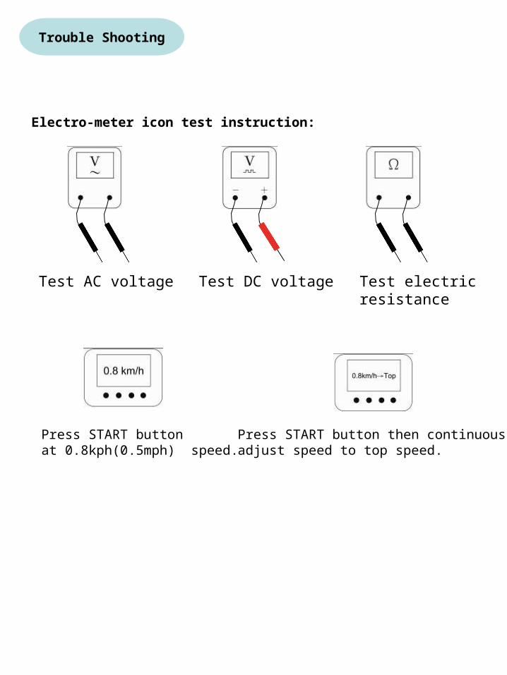
Electro-meter icon test instruction:
Test AC voltage
Press START button at 0.8kph(0.5mph) speed.
Press START button then continuous adjust speed to top speed.
Test DC voltage Test electricresistance
Trouble Shooting

NO DISPLAY REPAIR-1
230 VACAT OUTLET
IS AC LIGHT ON SWITCH ?
CHECK 8PIN CONNECTION ON
RELAY BOARD
CHECK 6PIN CONNECTOR
FROM RELAY BOARD TO CONTROL BOARD
CHECK VOLTAGE L1 L2 ON CONTROL
BOARDFig. 4
CHECK VOLTAGE FROM PIN 17V 10V TEST
PIN 10V ON CONTROLBOARDFig. 5
CHECK 8PIN CONNECTOR AT
COMPUTER
IS POWER SWITCH ON ?
IS THE CIRCUIT BREAKER TRIPPED ?
Fig. 1
CHECK VOLTAGE ACROSS
CIRCUIT BREAKERFig. 2
CHECK VOLTAGE ACROSS SWITCH
CHECK WIRE CONNECTION
SWITCH ON
RESET
REPLACE CIRCUIT BREAKER
REPLACESWITCH
REPLACE COMPUTER
CHECK ASSEMBLE8PIN CABLE
RECONNECT
REPLACE TRANSFORMER
CHECK HOME CIRCUIT BREAKER
REPLACE 8PIN CABLE OR RECONNECT
RECONNECT
IS SAFETY KEY INSERTED?
INSERTSAFETY KEY OR REPLACE
NO
NO
NO
NO
YES
YES
YES
YES NOYES
230 VAC
230 VAC
0 VAC
0 VAC
230 VAC
GOOD
GOOD
GOOD
GOOD
0 VAC
0 VAC
10 TO 12 VAC
BAD
BAD
BAD
BAD
RECONNECT
CHECK VOLTAGE FROM POWER LEAD
REPLACE POWER CORD
0 VAC
230 VAC
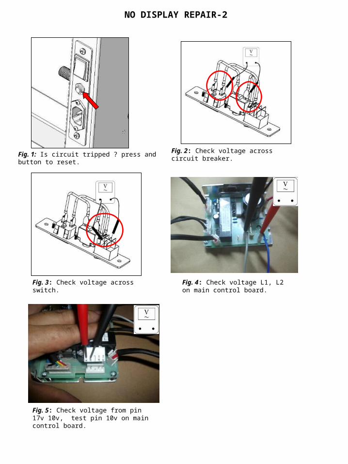
Fig. 1: Is circuit tripped ? press andbutton to reset.
Fig. 2: Check voltage across circuit breaker.
Fig. 3: Check voltage across switch. Fig. 4: Check voltage L1, L2 on main control board.
Fig. 5: Check voltage from pin 17v 10v, test pin 10v on main control board.
NO DISPLAY REPAIR-2
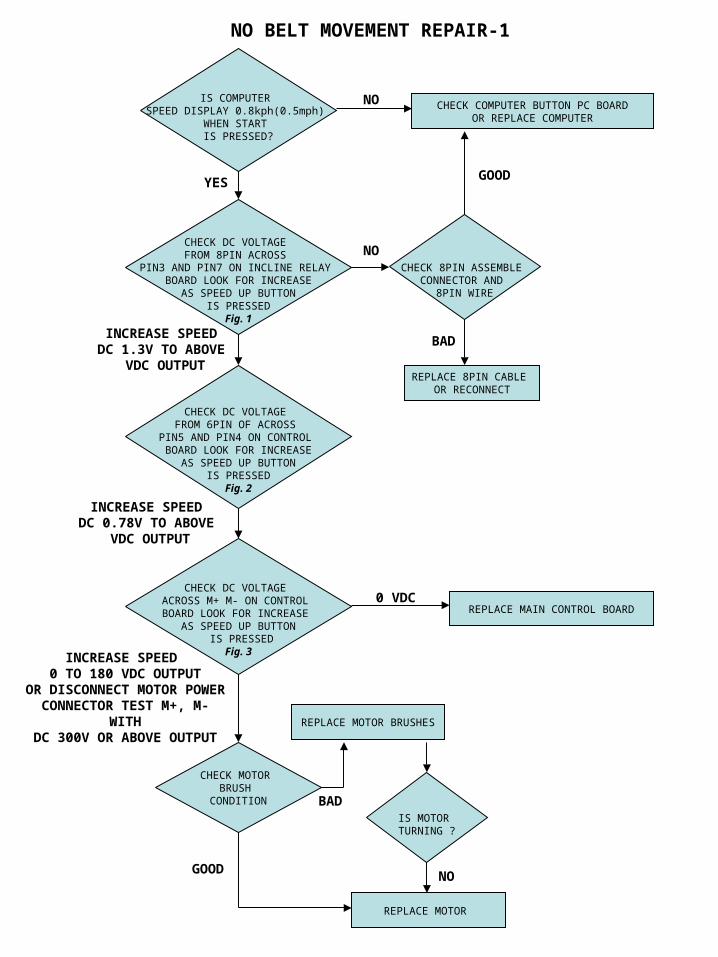
NO BELT MOVEMENT REPAIR-1
IS COMPUTER SPEED DISPLAY 0.8kph(0.5mph)
WHEN START IS PRESSED?
CHECK COMPUTER BUTTON PC BOARDOR REPLACE COMPUTER
NO
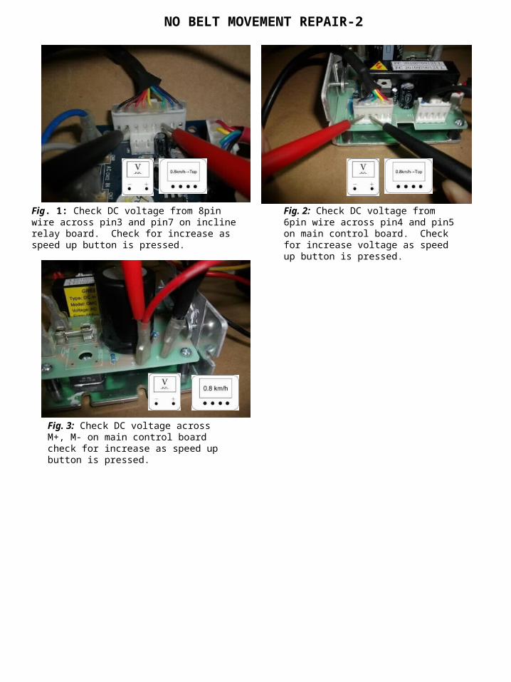
CHECK DC VOLTAGE FROM 8PIN ACROSS
PIN3 AND PIN7 ON INCLINE RELAY BOARD LOOK FOR INCREASE
AS SPEED UP BUTTON IS PRESSED
Fig. 1
YES
CHECK 8PIN ASSEMBLE CONNECTOR AND
8PIN WIRE
INCREASE SPEED DC 1.3V TO ABOVE
VDC OUTPUT
CHECK DC VOLTAGE FROM 6PIN OF ACROSS
PIN5 AND PIN4 ON CONTROL BOARD LOOK FOR INCREASE
AS SPEED UP BUTTON IS PRESSED
Fig. 2
INCREASE SPEED DC 0.78V TO ABOVE
VDC OUTPUT
CHECK DC VOLTAGE ACROSS M+ M- ON CONTROL BOARD LOOK FOR INCREASE
AS SPEED UP BUTTON IS PRESSED
Fig. 3INCREASE SPEED 0 TO 180 VDC OUTPUT
OR DISCONNECT MOTOR POWER
CONNECTOR TEST M+, M- WITHDC 300V OR ABOVE OUTPUT
CHECK MOTOR BRUSH
CONDITION
REPLACE MOTOR BRUSHES
BADIS MOTOR TURNING ?
REPLACE MOTOR
NOGOOD
REPLACE MAIN CONTROL BOARD0 VDC
REPLACE 8PIN CABLE OR RECONNECT
BAD
GOOD
NO
NO BELT MOVEMENT REPAIR-2
Fig. 2: Check DC voltage from 6pin wire across pin4 and pin5 on main control board. Check for increase voltage as speed up button is pressed.
Fig. 1: Check DC voltage from 8pin wire across pin3 and pin7 on incline relay board. Check for increase as speed up button is pressed.
Fig. 3: Check DC voltage across M+, M- on main control board check for increase as speed up button is pressed.
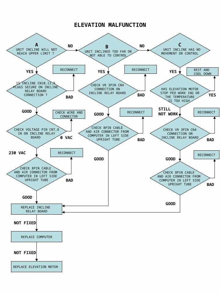
ELEVATION MALFUNCTION
A UNIT INCLINE WILL NOT REACH UPPER LIMIT ?
IS INCLINE CN10,11,9 PLUGS SECURE ON INCLINE
RELAY BOARD CONNECTION ?
CHECK VOLTAGE PIN CN7,8 IN ON INCLINE RELAY
BOARD
B UNIT INCLINED TOO FAR OR
NOT ABLE TO CONTROL
C UNIT INCLINE HAS NO
MOVEMENT OR CONTROL
HAS ELEVATION MOTORSTOP PED WORK ING OR
THE TEMPERATURE IS TOO HIGH
CHECK VR 3PIN CN4 CONNECTION ON
INCLINE RELAY BOARD
CHECK VR 3PIN CN4CONNECTION ON
INCLINE RELAY BOARD
YES RECONNECT
GOODGOOD CHECK WIRE AND
CONNECTOR
0 VAC
REPLACE INCLINE RELAY BOARD
230 VAC
YES RECONNECT
YESBAD
REPLACE COMPUTER
GOOD
REPLACE ELEVATION MOTOR
NOT FIXED
REST AND COOL DOWN
GOOD
YES
BAD
RECONNECT
BAD
STILLNOT WORK
NO NO
CHECK 8PIN CABLE AND AIR CONNECTOR FROM
COMPUTER IN LEFT SIDEUPRIGHT TUBE
RECONNECT
BAD
CHECK 8PIN CABLE AND AIR CONNECTOR FROM
COMPUTER IN LEFT SIDEUPRIGHT TUBE
CHECK 8PIN CABLE AND AIR CONNECTOR FROM
COMPUTER IN LEFT SIDEUPRIGHT TUBE
RECONNECT
RECONNECT
BAD
BAD
GOOD
GOOD
NOT FIXED
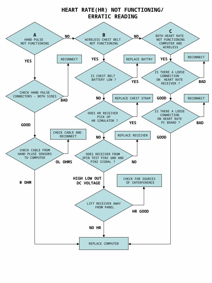
HEART RATE(HR) NOT FUNCTIONING/ERRATIC READING
AHAND PULSE
NOT FUNCTIONING
CBOTH HEART RATE NOT FUNCTIONING
COMPUTER ANDWIRELESS
BWIRELESS CHEST BELT
NOT FUNCTIONING
CHECK HAND PULSECONNECTORS - BOTH SIDES
CHECK CABLE FROM HAND PLUSE SENSORS
TO COMPUTER
IS CHEST BELT BATTERY LOW ?
DOES HR RECEIVER PICK UP
HR SIMULATOR ?
DOES RECEIVER FROM 3PIN TEST PIN1 GND AND
PIN2 SIGNAL ?
IS THERE A LOOSE CONNECTION
ON HEART RATE RECEIVER ?
IS THERE A LOOSE CONNECTION
ON HEART RATE PC BOARD ?
RECONNECT
BAD
GOOD
0 OHM
CHECK CABLE AND RECONNECT
OL OHMS
REPLACE BATTRY
REPLACE CHEST STRAP
YES
YES
NO
HIGH LOW OUT DC VOLTAGE
REPLACE RECEIVER
NO
NO
RECONNECT
RECONNECT
BAD
GOOD
BAD
GOOD
REPLACE COMPUTER
LIFT RECEIVER AWAY FROM PANEL
NO HR
CHECK FOR SOURCES OF INTERFERENCE
HR GOOD
YES YES YES
NO NO