Embed Size (px)
Citation preview

SERVICE MANUAL
EXPLORER® BALANCESEXPLORER® PRO BALANCESVOYAGER® BALANCES
99 Washington Street Melrose, MA 02176 Phone 781-665-1400Toll Free 1-800-517-8431
Visit us at www.TestEquipmentDepot.com


The information contained in this manual is believed to be accurate at the time of publication, but OhausCorporation assumes no liability arising from the use or misuse of this material. Reproduction of this materialis strictly prohibited.
Material in this manual is subject to change.
© Copyright 2003 Ohaus Corporation, all rights reserved.® Registered trademark of Ohaus Corporation.
SERVICE MANUAL
EXPLORER®BALANCESEXPLORER® PRO BALANCESVOYAGER® BALANCES
>O/T<
>O/T<
OHAUS ®
Stable
gPrint
Setup
Units
Mode
Enter
>O/T<
>O/T<
OHAUS ®
Stable
g
Setup
Units
Mode
Enter
*R %DFN+HOS
3ULQW
(QWHU
2Q 2II
0.0
WEIGHT
0%
100%
CONTRAST
GRAMSSTABLE
MOVE HIGHLIGHT
CONTRAST
MAIN MENU
0.00
BASIC WEIGHING
0%
100%GRAMS
STABLEEnter
Go BackHeip
>O/T<
>O/T<
PRESS <ENTER> FOR MENU
>O/T<
>O/T<
Enter
Go BackHelp
OHAUS ®
0.000
BASIC WEIGHING
0%
100%GRAMS
STABLE
PRESS <ENTER> FOR MENU
PRECISION HIGH CAPACITY ANALYTICAL
PRECISION HIGH CAPACITY ANALYTICAL
PRECISION HIGH CAPACITY ANALYTICAL
Explorer®
Explorer Pro®
Voyager®


i
TABLE OF CONTENTS
CHAPTER 1 INTRODUCTION1.1 Introduction .......................................................................................... 1-11.2 Service Facilities .................................................................................... 1-21.3 Tools and Test Equipment Required ...................................................... 1-3
1.3.1 Special Tools .................................................................................. 1-31.3.2 Standard Tools and Test Equipment .............................................. 1-3
1.4 Test Masses Required ............................................................................ 1-31.5 Specifications ......................................................................................... 1-4
CHAPTER 2 DIAGNOSIS2.1 Troubleshooting ...................................................................................... 2-12.2 Diagnostic Guide .................................................................................... 2-1
2.2.1 Diagnosis ........................................................................................ 2-12.3 Explorer / Voyager Error Code Table ...................................................... 2-32.4 Explorer Pro Error Code Table ............................................................... 2-5
CHAPTER 3 REPAIR PROCEDURES3.1 Repair Procedures .................................................................................. 3-1
3.1.1 Analytical Load Cell Removal ........................................................ 3-13.1.2 Analytical Load Cell Replacement.................................................. 3-23.1.3 Analytical Load Cell Position Sensor Adjustment ........................... 3-33.1.4 Analytical Load Cell Position Sensor Adustment Without Test Points 3-43.1.5 Analytical Load Cell Load Flexure (Vertical Link) Removal ............ 3-43.1.6 Analytical Load Cell Load Flexure (Vertical Link) Installation ......... 3-43.1.7 Analytical Load Cell Upper Flexure Arm and Lower Flexure Arm
Removal/ Installation ...................................................................... 3-53.1.8 Removing the Lever and Coil ......................................................... 3-63.1.9 Replacing the Vertical Flexures (Pillow Block Bearings) ................ 3-63.1.10 Replacing the Lever and Coil ......................................................... 3-73.1.11 Monoblock Load Cell Removal Precision Top Loader Balance and
Analytical ........................................................................................ 3-73.1.12 Monoblock Load Cell Replacement for Precision Top Loader
and Analytical Balances ................................................................. 3-83.1.13 Position Sensor Assembly Removal from Monoblock in Precision ......
Top Loader Balance ....................................................................... 3-93.1.14 Installing the Position Sensor Assembly for Monoblock Precision
Top Loader Balance ..................................................................... 3-103.1.15 Changing the Load Cell Board Precision Top Loader Balance .... 3-103.1.16 Removing the Force Coil Lever from Monoblock in Precision Top
Loader Balance ............................................................................ 3-113.1.17 Installing the Force Coil Lever Assembly in Monoblock for Precision ..
Top Loader Balance ..................................................................... 3-123.1.18 Vertical Stop Adjustment for Monoblock in Precision Top Loader
Balance ........................................................................................ 3-13
Page No.
ii
TABLE OF CONTENTS (Cont.)
3.1.19 Monoblock Load Cell Removal from High Capacity Top LoaderBalance ........................................................................................ 3-14
3.1.20 Calibration Motor Removal from High Capacity Top LoaderBalance ........................................................................................ 3-14
3.1.21 Position Sensor Assembly Removal from Monoblock in HighCapacity Top Loader Balance ...................................................... 3-15
3.1.22 Installing the Position Sensor Assembly for Monoblock High CapacityHigh Capacity Top Loader Balance .............................................. 3-15
3.1.23 Removing the Force Coil Lever assembly from Monoblock inHigh Capacity Top Loader Balance .............................................. 3-15
3.1.24 Installing the Force Coil Lever Assembly in Monoblock in HighCapacity Top Loader Balance ...................................................... 3-16
3.1.25 Installing Monoblock and Assembling Position Sensor for HighCapacity Top Loader Balance ...................................................... 3-16
3.1.26 Changing Servomotor on High Capacity Top Loader Balance ..... 3-173.1.27 Vertical Stop Adjustment for Monoblock in High Capacity Top
Loader Balance ............................................................................ 3-183.2 Replacement of Major Components...................................................... 3-19
3.2.1 Analytical Balances Main Printed Circuit Board (PCB) ................. 3-193.2.2 Analytical Balance Position Sensor PC Board ............................. 3-213.2.3 Precision Top Loader Balances Main Printed Circuit board (PCB)3-213.2.4 High Capacity Top Loader Balance Main Printed Circuit Board (PCB)
and Power Supply (PCB) .............................................................. 3-233.2.5 High Capacity Top Loader Balance Connector Printed Circuit
Board (PCB) ................................................................................. 3-243.2.6 Removing the Display Module on Explorer Precision Top Loader
Balances ....................................................................................... 3-243.2.7 Removing the Display Module on Explorer High Capacity Top
Loader Balances ........................................................................... 3-253.2.8 Display Printed Circuit Board ........................................................ 3-263.2.9 Membrane Switch Replacement ................................................... 3-273.2.10 Replacing the Display................................................................... 3-283.2.11 Removing the Display Module Voyager and Explorer Pro Models3-293.2.12 Display PCB/LCD Assembly Replacement .................................. 3-303.2.13 Bulb Replacement ........................................................................ 3-31
CHAPTER 4 TESTING4.1 Testing .......................................................................................... 4-1
4.1.1 Operational Test ............................................................................. 4-14.1.1.1 Segment Display Test ....................................................... 4-1
4.2 Performance Tests All Balances ............................................................. 4-24.2.1 Precision/Repeatability Test ........................................................... 4-24.2.2 Off-Center Load Test ....................................................................... 4-24.2.3 Linearity Test .................................................................................. 4-84.2.4 RS232 Communication Test ........................................................... 4-9

iii
CHAPTER 5 DRAWINGS AND PARTS LISTS5-1 Drawings and Parts Lists ........................................................................ 5-15-2 Parts Lists .... ......................................................................................... 5-3
5.2.1 Precision Top Loader Base Parts List ............................................ 5-35.2.2 Analytical Base Parts List ............................................................... 5-55.2.3 Precision Top Loader Base Parts List ............................................. 5-75.2.4 Analytical Load Cell Parts List ........................................................ 5-95.2.5 Precision Top Loader Monoblock Load Cell Parts List ................. 5-115.2.6 High Capacity Top Loader Balance Parts List .............................. 5-135.2.7 High Capacity Top Loader Balance Parts List .............................. 5-155.2.8 Monoblock High Capacity Top Loader Balance Parts List ............ 5-175.2.9 Explorer Display Parts List ............................................................ 5-195.2.10 Explorer High Capacity Parts list .................................................. 5-215.2.11 Explorer Pro, Voyager Display Parts List ...................................... 5-235.2.12 Voyager, Explorer Pro, High Capacity Parts List .......................... 5-25
APPENDIX A - EXPLORER EP LOADERA.1 Requirements for EP Loader.................................................................. A-1A.2 Limitations ......................................................................................... A-1A.3 Installing EP Loader Software................................................................ A-1A.4 Run EP Loader Software ....................................................................... A-1A.5 Setup the Balance in Manufacturing Mode ............................................ A-2A.6 Connect the Balance to a PC................................................................. A-2A.7 Personality Data Label Entry ................................................................. A-3A.8 Temperature Compensation (TC) Data Entry ........................................ A-5A.9 Downloading Personality Data and/or TC Data into the Balance .......... A-7A.10 Saving Personality Data and TC Data ................................................... A-7A.11 Opening Data Files ................................................................................ A-7A.12 Clear EP Loader .................................................................................... A-7A.13 Confirm TC Download ........................................................................... A-7
APPENDIX B - EXPLORER PRO EP LOADERB.1 Requirements for EP Loader.................................................................. B-1B.2 Installing EP Loader Software................................................................ B-1B.3 Run EP Loader Software ....................................................................... B-1B.4 Setup the Balance in Manufacturing Mode ............................................ B-2B.5 Connect the Balance to a PC................................................................. B-3B.6 Temperature Compensation (TC) Data Entry ........................................ B-3B.7 Personality Data label Entry .................................................................. B-6B.8 Downloading Personality Data and/or TC Data into the Balance .......... B-8B.9 Saving Personality Data and TC Data ................................................... B-8B.10 Opening Data Files ................................................................................ B-8B.11 Clear EP Loader .................................................................................... B-8B.12 Confirm TC Download ........................................................................... B-8
TABLE OF CONTENTS (Cont.)

iv
LIST OF TABLES
TABLE NO. TITLE PAGE NO.
1-1 Calibration Points .............................................................................. 1-31-2 Analytical Specifications ................................................................... 1-41-3 Precision Top Loader Specifications ................................................. 1-41-4 High Capacity Top Loader Specifications ......................................... 1-42-1 Diagnostic Guide ............................................................................... 2-22-2 Explorer Voyager Error Codes .......................................................... 2-32-3 Information Messages ....................................................................... 2-42-4 Explorer Pro Error codes ................................................................... 2-54-1 Types of Performance Tests .............................................................. 4-24-2 Center Load Test Masses .................................................................. 4-85-1 Precision Top Loader Base Parts List ............................................... 5-35-2 Analytical Base Parts List .................................................................. 5-55-3 Precision Top Loader Base Parts List ............................................... 5-75-4 Analytical Load Cell Parts List ........................................................... 5-95-5 Precision Top Loader Monoblock Load Cell Parts List .................... 5-115-6 High Capacity Top Loader Balance Parts List (Sheet 1) ................. 5-135-6 High Capacity Top Loader Balance Parts List (Sheet 2) ................. 5-155-7 Monoblock High Capacity Top Loader Parts List ............................ 5-175-8 Explorer Display Parts List .............................................................. 5-195-9 Explorer High Capacity Parts List .................................................... 5-215-10 Explorer Pro, Voyager Display Parts List ......................................... 5-235-11 Voyager, Explorer Pro, High Capacity Parts List ............................. 5-25
TABLE OF CONTENTS (Cont.)
APPENDIX C - PRODUCTION MODE CALIBRATIONC.1 Preparation ......................................................................................... C-1C.2 Manufacturing Calibration (MFg) Procedure .......................................... C-1C.3 Manufacturing Weight Calibration (MFgWt) Procedure .......................... C-2
APPENDIX D - REPLACING BOTTOM DISPLAY BOARDD.1 Replacing the Bottom Display Board on Voyager, Explorer Pro and Voyager
Pro Balance ......................................................................................... D-1D.2 Explorer Pro, Voyager and Voyager Pro flash Instructions .................... D-1

v
TABLE OF CONTENTS (Cont.)
LIST OF ILLUSTRATIONS
FIGURE NO. TITLE PAGE NO.3-1 Analytical Sensor Board Adjustment Locations and Connections ..... 3-33-2 Analytical Sensor Board Adjustment ................................................. 3-43-3 Removing the Vertical Flexure .......................................................... 3-43-4 Installing Vertical Flexure .................................................................. 3-43-5 Installing the Shims ........................................................................... 3-53-6 Hanger Positioning ............................................................................ 3-53-7 Lever Removal/IInstallation ............................................................... 3-63-8 Vertical Guide (Pillow Block Bearing) Installation ............................. 3-63-9 Installing Lever and Coil .................................................................... 3-73-10 Removing Position Sensor Assembly from Monoblock .................... 3-93-11 Position Sensor Assembly Mounting ............................................... 3-103-12 Changing Load Cell Board .............................................................. 3-103-13 Monoblock Assembly ...................................................................... 3-113-14 Contact Board Removal .................................................................. 3-113-15 Force Coil Removal ......................................................................... 3-113-16 Force Coil Lever Installation ............................................................ 3-123-17 Monoblock Mounting ....................................................................... 3-123-18 Position Sensor Connections .......................................................... 3-133-19 Calibration Motor Removal .............................................................. 3-143-20 Position Sensor Assembly Mounting ............................................... 3-153-21 Force Coil Removal ......................................................................... 3-153-22 Force Coil Lever Installation ............................................................ 3-163-23 Installation Monoblock and Position Sensor .................................... 3-163-24 Servomotor Installation .................................................................... 3-173-25 Position Sensor Connections .......................................................... 3-183-26 Display Removal/Installation for Explorer Precision Top Loader
Balance ........................................................................................ 3-253-27 Display Removal/Installation for Explorer High Capacity Top Loader
Balance ........................................................................................ 3-263-28 Rear View of Display PCB Assembly .............................................. 3-273-29 Membrane Switch Cable Routing .................................................... 3-283-30 Display Removal/Installation ........................................................... 3-293-31 Rear View of Display PCB Assembly .............................................. 3-303-32 LCD Assembly Bulb Replacement .................................................. 3-324-1 Segment Display ............................................................................... 4-14-2 LFT Displays ..................................................................................... 4-14-3 Countdown Display ........................................................................... 4-14-4 Analytical Off-Center Load Adjustments Diagram ............................. 4-34-5 Monoblock Off-Center Load .............................................................. 4-44-6 Monoblock Adjustments .................................................................... 4-6

vi
TABLE OF CONTENTS (Cont.)
LIST OF ILLUSTRATIONS
FIGURE NO. TITLE PAGE NO.
5-1 Overall Exploded View of Precision Top Loader Balance ................. 5-25-2 Overall Exploded View of Analytical Balance ................................... 5-45-3 Exploded View of Precision Top Loader Base Assembly.................. 5-65-4 Exploded View of Analytical Load Cell ............................................. 5-85-5 Exploded View of Monoblock Load Cell for Precision Top Loader ..5-105-6 Overall Exploded of High Capacity Top Loader Balance (Sht 1) ..... 5-125-6 Overall Exploded of High Capacity Top Loader Balance (Sht 2) ..... 5-145-7 Exploded View of Monoblock Load Cell for High Capacity Top
Loader Balance ............................................................................... 5-165-8 Exploded View of Explorer Display ................................................. 5-185-9 Exploded View of Explorer High Capacity Display .......................... 5-205-10 Exploded View of Explorer Pro, Voyager Display ........................... 5-225-11 Exploded View of Voyager, Explorer Pro High Capacity Display .... 5-24A-1 RF Shield ......................................................................................... A-3A-2 Personality Data ............................................................................... A-3A-3 TC Data ......................................................................................... A-5B-1 RF Shield ......................................................................................... B-2B-2 TC Data ......................................................................................... B-3B-3 Personality Data ............................................................................... B-6

1-1
CHAPTER 1 INTRODUCTION
1.1 INTRODUCTIONThis service manual contains the information needed to perform routine maintenance and service on the Ohaus Explorer®,Explorer Pro® and Voyager® balances. There are three basic configurations of balances: Analytical, Precision Top Loaderand High Capacity Top Loader. The High Capacity Top Loader balances are rated from 12,000 grams to 32,000 gramscapacity and contain different components than the lower capacity Precision Top Loader balances. The procedures in thismanual assume the technician performing them has a working knowledge of the use of standard hand tools and the repairand use of precision instruments.
The service strategy for Explorer balances is the replacement of PC boards, membrane switches and most case parts. Thetransducers are to be repaired. Only parts listed in the parts list are replaceable.
To service an Explorer Pro or Voyager balance, the display module must be removed and an Explorer display modulesubstituted. This is required in order to use the service software that is in the processor that is located on the Main PCB.See illustration below.
Explorer
PRECISION
Explorer Pro Voyager
PRECISION
0.00
BASIC WEIGHING
0%
100%GRAMS
STABLEEnter
Go BackHeip
>O/T<
>O/T<
PRESS <ENTER> FOR MENU
PRECISION
>O/T<
>O/T<
Enter
Go BackHelp
OHAUS ®
0.000
BASIC WEIGHING
0%
100%GRAMS
STABLE
PRESS <ENTER> FOR MENU
*R %DFN+HOS
3ULQW
(QWHU
2Q 2II
0.0
WEIGHT
0%
100%
CONTRAST
GRAMS
STABLE
MOVE HIGHLIGHT
CONTRAST
MAIN MENU
ANALYTICAL ANALYTICAL
HIGH CAPACITY HIGH CAPACITY HIGH CAPACITY
Display Module
Display Module
>O/T<
>O/T<
OHAUS ®
Stable
gPrint
Setup
Units
Mode
Enter

1-2
CHAPTER 1 INTRODUCTION
1.1 INTRODUCTION (Cont.)The contents of this manual is contained in five chapters with three appendices.
Chapter 1 Introduction - Contains information regarding service facilities, tools, test equipment, calibration massesand specifications.
Chapter 2 Diagnosis - Contains a diagnostic guide for troubleshooting problems and error code tables.
Chapter 3 Repair Procedures - Contains disassembly/assembly and replacement procedures.
Chapter 4 Testing - Contains an operational test, a segment display test and performance tests.
Chapter 5 Drawings and Parts Lists - Contains exploded view drawings with associated parts lists.
Appendix A Explorer EP Loader-Contains information on loading software to place the Explorer balance in amanufacturing mode to download temperature and personality data.
Appendix B Explorer Pro EP Loader-Contains information on loading software to place the Explorer Pro balancein a manufacturing mode to download temperature and personality data.
Appendix C Production Mode Calibration-Contains calibration information in a production mode.
Before servicing the balance, you should be familiar with the Instruction Manual which is packed with every balance.
1.2 SERVICE FACILITIESDO NOT SERVICE the balance:
• Next to open windows or doors causing drafts or rapid temperature changes.
• Near air conditioning or heat vents.
• Near vibrating, rotating or reciprocating equipment.
• Near magnetic fields or equipment that generates magnetic fields.
• On an unlevel work surface.
• Allow sufficient space around the instrument for ease of operation and keep away fromradiating heat sources.
>O/T<
>O/T< 0.00
WEIGHT
0%
100%
CONTRAST
GRAMS
STABLE
MOVE HIGHLIGHT
CONTRAST
MAIN MENU Enter
Go BackHeip
OHAUS ®
>O/T<
>O/T< 0.00
WEIGHT
0%
100%
CONTRAST
GRAMS
STABLE
MOVE HIGHLIGHT
CONTRAST
MAIN MENU Enter
Go BackHeip
OHAUS ®
>O/T<
>O/T< 0.00
WEIGHT
0%
100%
CONTRAST
GRAMS
STABLE
MOVE HIGHLIGHT
CONTRAST
MAIN MENU Enter
Go BackHeip
OHAUS ®

1-3
CHAPTER 1 INTRODUCTION
1.3 TOOLS AND TEST EQUIPMENT REQUIREDIn order to properly service the Ohaus Explorer balances, certain Ohaus special tools and test items are required in additionto standard electronic tool kits. These items are listed as follows:
1.3.1 Special Tools
1. 476000-03 Monoblock service tool kit2. 476001-02 Analytical service tool kit3. 11108525 Explorer Display Module, Capacities to 8kg4. 450111-010 Explorer Display Module, Capacities over 12kg5. AS017-09 Interface cable 9 Pin or AS017-02 Interface cable 25 Pin.
1.3.2 Standard Tools and Test Equipment
1. Digital Voltmeter (DVM) - Input impedance of at least 10 megohms in the 1 Volt dc position.
2. Torx driver Set
3. Torque wrench (optional) with a Phillips head bit, Tork bits, Allen bits, SAE and Metric
4. Box wrench, 7mm
5. Nutdriver, 3/16"
6. Hex or Allen key wrenches, 7/16", 9/64" or 3/32", M3 SAE and Metric Set
7. Other assorted hand tools, tweezers, adjustable open wrenches, etc.
8. Soldering iron (50 watt) and solder (rosin core solder, not acid core).
9. Solder remover.
10. Computer with at least 1 com port.
11. A communications program similiar to Hyper Terminal (supplied with Windows).
1.4 TEST MASSES REQUIREDThe masses required to test the Ohaus Explorer balances must meet the requirements of ASTM Class 1 Tolerance. Thecalibration points are listed in Table 1-1. Use the least number of masses to reach the total.
TABLE 1-1. CALIBRATION POINTSLINEARITY SPAN
CAPACITY MASSES TOTALING MASSES TOTALING62g 20g/50g 50g
110g 50g/100g 100g210g 100g/200g 200g410g 200g/400g 400g610g 200g/500g 500g
2100g 1000g/2000g 2000g4100g 2000g/4000g 4000g6100g 2000g/5000g 5000g8100g 4000g/8000g 8000g
12000g 5000g/10000g 10000g22000g 10000g/20000g 20000g32000g 15000g/30000g 30000g

1-4
CHAPTER 1 INTRODUCTION
Capacity (g) 210 410 100/410 610 2100 4100 1000/4100 4100 6100 8100
Readability (g) 0.001 0.001/0.01 0.01 0.01/0.1 0.1
Repeatability (Std. dev.) (g) 0.0005 0.0005/0.005 0.005 0.01/0.05 0.05
Linearity (g) (+) 0.002 0.002/0.005 0.02 0.02/0.05 0.1
Tare range Full capacity by subtraction
Stabilization time <3 seconds
Sensitivity drift PPM/°C 4 3 4 3 4 3 4 3(10°C - 30°C)
Operating temperature range: .................. w/internal calibration 10° to 40°C/50° to 104°F .................. w/o internal calibration 10° to 30°C/50° to 86°F ..................
Power requirements External Adapter, 100-120 V ac, 220 V ac, 50/60 HzPlug configuration for US, Euro, UK & Australia
TABLE 1-3. PRECISION TOP LOADER SPECIFICATIONS
Capacity (g) 62 110 210 100/210
Readability (mg) 0.1 0.1/1
Repeatability (Std. dev.) (mg) 0.1 0.1/0.5
Linearity (mg) (+) 0.2 0.2/0.5
Tare range Full capacity by subtraction
Safe overload capacity 150% of capacity
Stabilization time <4 seconds
Sensitivity drift PPM/°C 3 ..................(10°C - 30°C)
Operating temperature range: .................. w/internal calibration 10° to 40°C/ 50° to 104°F .................. w/o internal calibration 10° to 30°C/50° to 86°F
Power requirements External Adapter, 100-120 V ac, 220 V ac, 50/60 HzPlug configuration for US, Euro, UK & Australia
1.5 SPECIFICATIONSComplete specificatons for the Ohaus Explorer balances are listed in Tables 1-2, 1-3 and 1-4. When a balance has beenserviced, it must meet the specifications listed in the table. Before servicing the balance, determine what specificationsare not met.
Capacity (g) 12,000 22,000 32,0000
Readability (g) 0.1
Repeatability (Std. dev.) (g) 0.1
Linearity (g) (+) 0.4
Tare range Full capacity by subtraction
Safe overload capacity 150% of capacity
Stabilization time <4 seconds
Sensitivity drift PPM/°C 3 ..................(10°C - 30°C)
Operating temperature range: .................. w/internal calibration 10° to 40°C/ 50° to 104°F ..................w/o internal calibration 10° to 30°C/50° to 86°F
Power requirements External Adapter, 100-120 V ac, 220 V ac, 50/60 Hz Plug configuration for US, Euro, UK, Japan & Australia
TABLE 1-4. HIGH CAPACITY TOP LOADER SPECIFICATIONS
TABLE 1-2. ANALYTICAL SPECIFICATIONS
2-1
CHAPTER 2 DIAGNOSIS
2.1 TROUBLESHOOTINGThis section of the manual specifies problem areas of the balance which can occur. Information is contained to isolatespecific problems using Table 2-1, Diagnostic Guide, and Error Codes, Tables 2-2 through 2-4. Follow all directions stepby step. Make certain that the work area is clean and use care when handling components of the balance.
2.2 DIAGNOSTIC GUIDETable 2-1 is a diagnostic guide designed to help locate the problem area quickly and easily. To use the table, first locatethe symptom that you are observing. Follow the symptom column and review the probable cause column and remedy column.The probable causes are listed with the most common cause first. If the first remedy does not fix the problem, proceed onto the next remedy. Before attempting to repair the balance, read all chapters of this manual to familiarize yourself with thebalance components and operation. Do not attempt repairs unless you fully understand the operation of the balance.
2.2.1 Diagnosis
1.Isolate and identify the symptom.
2.Refer to Table 2-1 Diagnostic guide and locate the symptom.
3.Follow the suggested remedies in the order that they appear.
4.Perform the indicated checks, or see the appropriate section of the manual.
5.Repair or replace the defective section of the balance.
NOTE:If more than one symptom is observed, it is necessary to approach onearea at a time, and also remember, that the symptoms may be interre-lated.
In the event that erratic or fluctuating weight readings are observed, it is necessary to isolate the problem to either themechanical area or the electronic area of the balance.
If a problem arises that is not covered in this manual, contact:
Ohaus Corporation19A Chapin RoadP.O. Box 2033Pine Brook, NJ 07058-2033 USATel: 973-377-9000Fax: 973-593-0359
In the United States call toll free, 800-526-0659 between 8:00 a.m. and 5:30 p.m. EST.
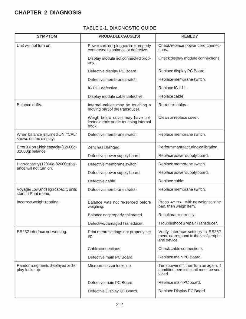
2-2
CHAPTER 2 DIAGNOSIS
PROBABLE CAUSE(S)
Power cord not plugged in or properlyconnected to balance or defective.
Display module not connected prop-erly.
Defective display PC Board.
Defective membrane switch.
IC U11 defective.
Display module cable defective.
Internal cables may be touching amoving part of the transducer.
Weigh below cover may have col-lected debris and is touching internalhook.
Defective membrane switch.
Zero has changed.
Defective power supply board.
Defective membrane switch.
Defective power supply board.
Defective cable.
Defective membrane switch.
Balance was not re-zeroed beforeweighing.
Balance not properly calibrated.
Defective/damaged Transducer.
Print menu settings not properly setup.
Cable connections.
Defective main PC Board.
Microprocessor locks up.
Defective main PC Board.
Defective Display PC Board.
SYMPTOM
Unit will not turn on.
Balance drifts.
When balance is turned ON, "CAL"shows on the display.
Error 3.0 on a high capacity (12000g-32000g) balance.
High capacity (12000g-32000g) bal-ance will not turn on.
Voyager Low and High capacity unitsstart in Print menu.
Incorrect weight reading.
RS232 interface not working.
Random segments displayed or dis-play locks up.
REMEDY
Check/replace power cord connec-tions.
Check display module connections.
Replace display PC Board.
Replace membrane switch.
Replace IC U11.
Replace cable.
Re-route cables.
Clean or replace cover.
Replace membrane switch.
Perform manufacturing calibration.
Replace power supply board.
Replace membrane switch.
Replace power supply board.
Replace cable.
Replace membrane switch.
Press O/T with no weight on thepan, then weigh item.
Recalibrate correctly.
Troubleshoot & repair Transducer.
Verify interface settings in RS232menu correspond to those of periph-eral device.
Check cable connections.
Replace main PC Board.
Turn power off, then turn on again. Ifcondition persists, unit must be ser-viced.
Replace main PC board.
Replace Display PC Board.
TABLE 2-1. DIAGNOSTIC GUIDE

2-3
CHAPTER 2 DIAGNOSIS
TABLE 2-1. DIAGNOSTIC GUIDE (Cont.)
Unstable readings.
Error message display.
Excessive air currents.
Vibration on table surface.
Defective/damaged Transducer.
Defective main PC Board.
Check environmental conditions.
Place balance on a stable surfaceor change averaging level.
Troubleshoot & replace Transducer.
Replace main PC Board.
See Error Codes list.
REMEDYPROBABLE CAUSE(S)SYMPTOM
2.3 EXPLORER / VOYAGER ERROR CODE TABLEThe Explorer and Voyager balances are equipped with software which will display an error condition when it occurs. Table2-2 Explorer/Voyager Error Codes, describes the various error codes which can appear on the display and specifies theprobable reason and remedy. Table 2-3 lists the error messages that can appear on the display. Table 2-4 lists the errorcodes for the Explorer Pro balance.
TABLE 2-2. EXPLORER VOYAGER ERROR CODESDisplays Error 1.0
Usually caused by static discharge. If the error persists replace the PCB.
Displays Error 1.1Temperature channel duty cycle out of range. Failed temperature sensor or broken wire between the temperature sensorand the PCB.
Displays Error 2.0Unable to stabilize within time limit after pressing the tare button. Look for something touching any moving part of thetransducer. Could be a problem with the transducer itself.
Displays Err 3.0The zero has changed enough to make the internal calibration data incorrect - perform MFG and MFGWT if the unit hasinternal calibration (AutoCal).
Displays Error 3.1Unable to get stable data during an internal calibration.1. Was the balance warmed up?2. Does the balance repeat? This would indicate a problem with the transducer.
Place a draft shield over the balance
Displays Err 3.2Incal motor has not stopped in time. Check motor, motor control and weight positioning setup.
Displays Error 8.0 & Error 8.1This is a hardware error. It could be caused by the PCB, Transducer or the inter-connections.
Displays Err 8.3Power on load out of range – Overload, extra weight on pan.
Displays Err 8.4Power on load out of range - Pan missing or wrong pan that is too light.

2-4
CHAPTER 2 DIAGNOSIS
Displays Err 8.5Internal calibration weight sensor indicates the weight is on the pan, Check the connection between the calibrationunit and the main PCB. Could be a problem with the calibration mechanism or the main PCB.
Displays Err 9.1Personality data corrupt. Reload using EP Loader.
Displays Err 9.2Serial number does not match. The serial number chip U10 was not transferred to a new PCB. If the correct U10can not be found the main PCB must be replaced with a configured PCB.
Displays Err 9.3Serial number does not match. Unplug and try again. If that fails reload personality data using EP Loader.
Displays Err 9.4Factory internal calibration data failed checksum. Perform MFG and MFGWT. If the problem persists reload theTC data. If the problem still persists the main PCB must be reconfigured at Ohaus.
Displays Err 9.5Factory calibration data failed checksum. Perform MFG and MFGWT. If the problem persists reload the TC data.If the problem still persists the main PCB must be reconfigured at Ohaus.
Displays Err 9.8User calibration data failed checksum. Perform MFG Calibration. For units with internal calibration also performMFGWT.
Displays Err 9.9Can not be fixed in the field, the unit has to be temperature compensated.
TABLE 2-2. EXPLORER VOYAGER ERROR CODES (Cont.)
TABLE 2-3. INFORMATION MESSAGES
CAL NOW If InCALTM (internal calibration) is installed. Message to recalibrate the balance. The message will remainuntil calibrated.
WARM UP The user tried to perform an internal calibration and this message will be flashed in the 14 segment field.The balance requires a 7 minute warm-up period. During warm-up, the user cannot select InCALTMfromthe menu.
SAVED This message is flashed when an item is changed in the menu and the new value is written to theEEPROM.
LOCKED This message is flashed when an item cannot be changed in the menu, because the menu is locked andthe Lock Switch is set locked.
LOW REF The message is flashed in parts counting or percent when the calculated reference weight is very low.
2.3 EXPLORER / VOYAGER ERROR CODE TABLE (Cont.)

2-5
CHAPTER 2 DIAGNOSIS
Displays Error 1.0Usually caused by static discharge. If the error persists replace the PCB
Displays Error 1.1Temperature channel duty cycle out of range. Failed temperature sensor or broken wire between the temperaturesensor and the PCB
Displays Error 2.0Unable to stabilize within time limit after pressing the tare button. Look for something touching any moving partof the transducer. Could be a problem with the transducer itself.
Displays Err 3.0The zero has changed enough to make the internal calibration data incorrect - perform MFG and MFGWT if theunit has internal calibration (AutoCal).
Displays Error 3.1Unable to get stable data during an internal calibration.
1. Was the balance warmed up?2. Does the balance repeat? This would indicate a problem with the transducer.Place a draft shield over the balance
Displays Err 3.2Incal motor has not stopped in time. Check motor, motor control and weight positioning setup.
Displays Error 8.0 & Error 8.1This is a hardware error. It could be caused by the PCB, Transducer or the inter-connections.
Displays Err 8.3Power on load out of range – Overload, extra weight on pan.
Displays Err 8.4Power on load out of range - Pan missing or wrong pan that is too light.
Displays Err 8.5Internal calibration weight sensor indicates the weight is on the pan, Check the connection between the calibrationunit and the main PCB. Could be a problem with the calibration mechanism or the main PCB.
Displays Err 9.1Personality data corrupt. Reload using EP Loader.
Displays Err 9.2Serial number does not match. The serial number chip U10 was not transferred to a new PCB. If the correct U10can not be found the main PCB must be replaced with a configured PCB.
Displays Err 9.3Serial number does not match. Unplug and try again. If that fails reload personality data using EP Loader.
2.4 EXPLORER PRO ERROR CODE TABLE
TABLE 2-4. EXPLORER PRO ERROR CODES

2-6
CHAPTER 2 DIAGNOSIS
TABLE 2-4. EXPLORER PRO ERROR CODES (Cont.)Displays Err 9.4
Factory internal calibration data failed checksum. Perform MFG and MFGWT. If the problem persists reload the TC data.If the problem still persists the main PCB must be reconfigured at Ohaus.
Displays Err 9.5Factory calibration data failed checksum. Perform MFG and MFGWT. If the problem persists reload the TC data. If theproblem still persists the main PCB must be reconfigured at Ohaus.
Displays Err 9.8User calibration data failed checksum. Perform MFG Calibration. For units with internal calibration also perform MFGWT.
Displays Err 9.9Can not be fixed in the field the unit has to be temperature compensated.
2.4 EXPLORER PRO ERROR CODE TABLE (Cont.)

3-1
CHAPTER 3 REPAIR PROCEDURES
3.1 REPAIR PROCEDURESDepending upon the capacity of the balance, one of three different types of load cells are used. The analytical balancescontain an analytical load cell or a Monoblock load cell and the top loader balances contain one of two styles of Monoblockload cells. This section of the manual contains detailed disassembly and assembly procedures on each of three types ofload cells. The removal of the load cell should only be attempted when it is determined that it requires parts replacement
3.1.1 Analytical Load Cell (9) RemovalRefer to Figures 5-2 and 5-3 in Chapter 5 for location of components called out in this procedure. To remove the AnalyticalLoad Cell, proceed as follows:
See Figure 5-2 for steps 1 through 4.
1.With the balance turned OFF and unplugged, open the Draft Shield door and remove the Pan (5).
2.Remove Cover Plate (6).
3.Inside of the Draft shield, remove two Screws (2) and Lockswitch Cover Seal (1).
4.Carefully lift the Draft Shield from the balance Base and set aside.
See Figure 5-3 for remaining steps.
5.Remove two Screws (3) which secure Shield (4) in place.
6.Remove Shield (4) from the balance.
7.Remove the two Screws (3) on top of the PC Board (11).
8.Remove the Hex Screws (14) and Washers (25) at the rear of the balance which secure the connectors onthe PC Board (11).
9.Disconnect the two cable connectors from the Load Cell going to J3 and J6 on the PC board as shown onFigure 5-3.The Load Cell (9). If internal calibration option is installed, disconnect cable to J4.
10. Carefully lift the PC Board (11) from the Base (18) there is a small cable from the Sensor Board which shouldalso be disconnected from the PC Board (not shown on Figure 5-3).
11. Remove the four screws (8) holding the Internal Calibration Mechanism (10) and lift out the Internal CalibrationMechanism. Avoid touching the internal calibration mass.
12. Turn the balance over on its side and while holding the Analytical Load Cell with one hand, remove the threeScrews (24) and Washers (23) from the bottom of the balance. The Load Cell can now be removed.
CAUTION
EXTREME CARE MUST BE EXERCISED SO AS NOT TO DAMAGETHE FLEXURE ARMS FLEXURES, THE RATIO BEAM FLEXURES,THE LOAD FLEXURE, OR ANY OTHER SUPPORT MEMBER. DAM-AGE TO ANY ONE OR MORE OF THESE COMPONENTS WILLDESTROY THE ACCURACY OF THE BALANCE.
NOTE:Visually inspect the Load Cell Assembly for bent, cracked, or distortedFlexures. Each Flexure should be perfectly straight. If it is determinedthat a Flexure requires replacement, refer to paragraph 4.3.6 for theUpper Flexure Arm and Lower Flexure Arm removal procedure.
3-2
CHAPTER 3 REPAIR PROCEDURES
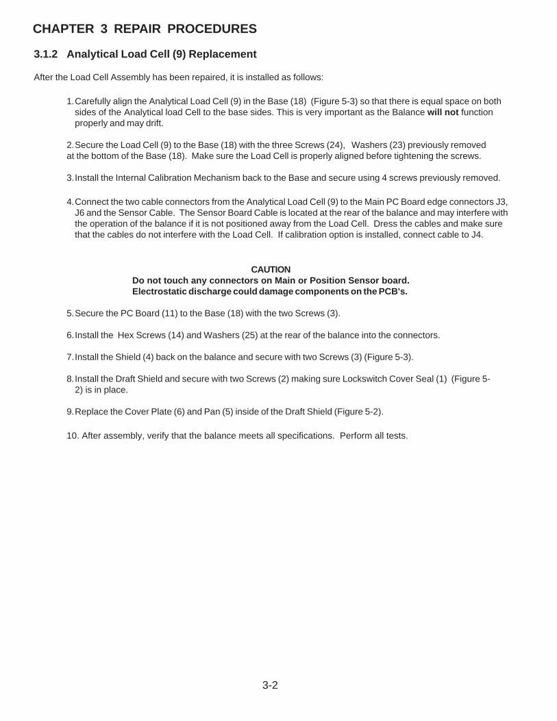
3.1.2 Analytical Load Cell (9) Replacement
After the Load Cell Assembly has been repaired, it is installed as follows:
1.Carefully align the Analytical Load Cell (9) in the Base (18) (Figure 5-3) so that there is equal space on bothsides of the Analytical load Cell to the base sides. This is very important as the Balance will not functionproperly and may drift.
2.Secure the Load Cell (9) to the Base (18) with the three Screws (24), Washers (23) previously removedat the bottom of the Base (18). Make sure the Load Cell is properly aligned before tightening the screws.
3.Install the Internal Calibration Mechanism back to the Base and secure using 4 screws previously removed.
4.Connect the two cable connectors from the Analytical Load Cell (9) to the Main PC Board edge connectors J3,J6 and the Sensor Cable. The Sensor Board Cable is located at the rear of the balance and may interfere withthe operation of the balance if it is not positioned away from the Load Cell. Dress the cables and make surethat the cables do not interfere with the Load Cell. If calibration option is installed, connect cable to J4.
CAUTIONDo not touch any connectors on Main or Position Sensor board.Electrostatic discharge could damage components on the PCB's.
5.Secure the PC Board (11) to the Base (18) with the two Screws (3).
6.Install the Hex Screws (14) and Washers (25) at the rear of the balance into the connectors.
7.Install the Shield (4) back on the balance and secure with two Screws (3) (Figure 5-3).
8.Install the Draft Shield and secure with two Screws (2) making sure Lockswitch Cover Seal (1) (Figure 5-2) is in place.
9.Replace the Cover Plate (6) and Pan (5) inside of the Draft Shield (Figure 5-2).
10. After assembly, verify that the balance meets all specifications. Perform all tests.

3-3
CHAPTER 3 REPAIR PROCEDURES
3.1.3 Analytical Load Cell Position Sensor Adjustment With Test PointsWhen the Analytical Load Cell Assembly (9) has been repaired either an Upper or lower Flexure Arm Assembly or VerticalFlexure has been replaced, it may be necessary to adjust the Position Sensor. Refer to Figures 3-1, 5-3 and 5-4.
1.Remove the Analytical Load Cell from the balance, see paragraph 3.1.1.
2.Plug the Position Sensor PCB Assembly Cable into the Main PC Board (11). DO NOT CONNECT THELOAD CELL CABLE.
3.Apply power to the balance.
4.Refer to Figure 3-1 and using a Digital Voltmeter set to measure dc voltage, connect the (DVM) to the twoterminal contacts located on the right hand side of the Sensor Board (51C) (See Figure 5-4) as follows:
Black or ground test lead to the negative terminal on the Sensor PC Board.Red or positive test lead to the positive terminal on the Sensor PC Board.
+ -ADJUSTMENT SCREWS
SENSOR PC BOARDPRECISION RESISTOR
CONNECTIONS
SENSOR CABLECONNECTIONS
Figure 3-1. Analytical Sensor Board Adjustment Locations and Connections.
5.Push down on the Pan Support which is located on top of the Transducer (brass fitting), the reading onthe DVM will be approximately +2.xxx volts dc.
6.Pull up on the Pan Support, the reading on the DVM will be approximately 2.xxx volts dc.
7.Adjust up stop for equal swing between readings in steps 5 and 6. See Figure 5-4 for location of stop screw.
8.Reassemble the balance, follow the procedure in paragraph 3.1.2.

3-4
CHAPTER 3 REPAIR PROCEDURES
When the Analytical Load Cell Assembly (9) has beenrepaired either an Upper or lower Flexure Arm Assembly orVertical Flexure has been replaced, it may be necessary toadjust the Position Sensor. Refer to Figures 3-2, 5-3 and 5-4.
1.Remove the Analytical Load Cell from the bal-ance, see paragraph 3.1.1.
2.Plug the Position Sensor PCB Assembly Cableinto the Main PC Board (11). Connect all cablesand ensure the Pan is in place.
3.Apply power to the balance.
4.Observe the weight display. Move the PositionSensor PCB until the display shows numbers.Carefully tighten the adjustment screws.
5.Reassemble the balance, follow the procedure inparagraph 3.1.2.
Figure 3-2. Analytical Sensor Board Adjustment Locations and Connections.
ADJUSTMENT SCREWS
SENSOR PC BOARDPRECISION RESISTOR
CONNECTIONS
SENSOR CABLECONNECTIONS
3.1.5 Analytical Load Cell Load Flexure(Vertical Link) Removal
1.To protect the Flexure at the Hanger, loosely inserttwo mounting screws (a). Do not tighten.
2.Loosen the lower flexure screw while holding theTorsion Protector (b).
3.Unscrew the upper screw (c).
4.Unscrew the lower screw and remove the flexureand spacers. Figure 3-3. Removing the Vertical Flexure.
3.1.4 Analytical Load Cell Position Sensor Adjustment Without Test Points
3.1.6 Analytical Load Cell Load Flexure(Vertical Link) Installation
1.Set the Load Cell on the sensor board.
2.Place the large Spacer (l) on the lever
3.Place the small Spacer (m) on the Hanger.
4.Lay the Flexure on the Spacers with the round holeat the top. The flexure should be aligned vertically
5.Tighten the upper screw.
6.Insert the lower flexure screw but do not tighten.Make sure the Torsion Protector is installed.
7.Loosen screws (a) Fig 3-3 and remove the shims.
8.Adjust the height of the hanger to 8 mm / 0.315 in.
9.Tighten the lower flexure screw insuring that thetorsion protector in touching the side of the hanger.
Refer to Figure 3-3.
Figure 3-4. Installing Vertical Flexure.
Refer to Figure 3-4.

3-5
CHAPTER 3 REPAIR PROCEDURES
1.At the top of the Load Cell Assembly (51), removethe two Screws and Washers which secure thePan Support to the Hanger.
2.Remove the three screws which secure BottomMounting Plate to Load Cell Base.
3.Remove Vertical Flexure per paragraph 3.1.5.
4.Carefully loosen the two Screws located at therear of the Upper Flexure Arm and the rear of theLower Flexure Arm (d). These are the screwswhich hold the Flexures in place. Do not touchthe two rear most screws with the nuts on top asthese are the adjustment screws.
5.At the front of the Load Cell Assembly (51), insertthe two Shims included in kit 476001-02 be-tween the Hanger and the Load Cell Base withthe open slotted end in first, see Figure 3-5.The slots should be aligned so that the screwholes in the Center post to the Load Cell Base arevisible.
3.1.7 Analytical Load Cell Upper Flexure Arm and Lower Flexure Arm Removal/InstallationRefer to Figures 3-5, 3-6 and 5-4 for the following procedure.
CAUTIONBefore the Upper or Lower Flexure Arms canbe removed, the the Load Flexure must beremoved and the Hanger secured to thebase of the Transducer with two screwsremoved from the Bottom Mounting Plate(a). This is necessary to prevent furtherdamage from occuring when trying to re-move and replace individual Flexures.
6.Take the two Screws removed from the PlatformMounting Assembly and install them in the Cen-ter Post through the slots in the Shims. Fingertighten the screws.
7.Fully tighten the two screws which hold the Shimsin place.
NOTE:Do not remove the Upper or Lower Flexure Armsunless there is evidence of damage to one or moreof the Flexure Links.
8.To remove the Upper Flexure Arm from the LoadCell Assembly (51), remove the four Screws andWashers, one at each Flexure point.
9.To remove the Lower Flexure Arm from the LoadCell Assembly (51), remove the four Screws andWashers, one at each Flexure point.
Figure 3-5. Installing the Shims.
Figure 3-6. Hanger Positioning.
10. Examine each Flexure. Each one must beperfectly straight. Replace any Flexure whichis bent, twisted, cracked or deformed in anymanner.
11. To replace a defective Flexure, remove theScrew and Washer which secures the Flexureto the Upper or Lower Flexure Arm. Replace asrequired.
12. To install Upper and or Lower Flexure Arms,perform steps 8 and 9 in reverse order.
13. Install Vertical Flexure per Paragraph 3.1.4.
14. Remove screws holding Shims and removeShims.
15. Secure Pan Support to Center Post with twoscrews
16. Install Bottom Mouting Plate with three screws.

3-6
CHAPTER 3 REPAIR PROCEDURES
3.1.8 Removing the Lever and Coil.
1.Remove the Hanger and shims.
2.Remove the Vane (e) from the Lever.
3.Remove the 4 screws (f) holding the magnetholder.
4.Remove the magnet holder.
CAUTION:The magnet is made of brittle material, careshould be taken not to break off pieces.
5.Note the original position of the vertical stop andturn it so that the ear on the Lever aligns with theslot.
6.Remove the Lateral Stop (g).
7.Unsolder the contact strips at the Lever board.
8.Remove the screws from the vertical guides (pillow block bearings) from the chassis. And lift theLever out.
Figure 3-7. Lever Removal/Installation.
3.1.9 Replacing the Vertical Flexures (PillowBlock Bearings)
1.Place the Lever on a flat surface and remove thebad Flexures.
2.The round hole of the Flexure goes to the Leverside.
3.Make sure the tops of the Flexures are flush withthe top of the Lever.
4.The distance from Flexure to Flexure is 46mm(1.81in)
Figure 3-8. Vertical Guide (Pillow Block Bearing)Installation.

3-7
CHAPTER 3 REPAIR PROCEDURES
3.1.10 Replacing the Lever and Coil.
1.Before replacing the Lever make sure the guideshave been checked or replaced in necessary, andthe magnet system is cleaned.
2.Place the lever in the chassis and lock by turningthe up/down stop to the original position.
3.Install the Ohaus fixture included in part number476001-020. This will give all the proper distances.
4.Install the lateral stop. Make sure the post iscentered in the hole.
5.Solder the contact strips. Make sure the strips areparallel.
6.Install the magnet holder.
7.Install the Vane and center it in the detector hous-ing.
8.Remove the fixture.
Figure 3-9. Installing Lever and Coil.
3.1.11 Monoblock Load Cell Removal Precision Top Loader Balance and AnalyticalRefer to Figures 5-1 and 5-3 in Chapter 5 for location of components called out in this procedure. To remove the MonoblockLoad Cell, proceed as follows:
See Figure 5-1 for steps 1 through 5.
1.With the balance turned OFF and unplugged, remove the Pan (1).
2.Remove Wind Shield (2) if applicable or Draft Shield.
3.Remove the four Corner Spacers (5) if required.
4.Remove two Screws (2) and Lockswitch Cover Seal (4).
5.Remove the Cover (6) from the Base.
See Figure 5-3 for remaining steps.
6.Remove the two Hex Screws (1) from the Subplatform (2) if required.
7.Remove the Subplatform (2) if required.
8.Remove two Screws (3) which secure Shield (4) in place.
9.Remove Shield (4) from the balance.

3-8
CHAPTER 3 REPAIR PROCEDURES
3.1.11 Monoblock Load Cell Removal Precision Top Loader Balance and Analytical (Cont.)
10. Remove the two Screws (3) on top of the PC Board (11).
11. Remove the Hex Screws (14) and Washers (25) at the rear of the balance which secure the connectors onthe PC Board (11).
12. Disconnect the two cable connectors from the Load Cell going to J2 and J6 on the PC board as shown onFigure 5-3.The Load Cell (9). If internal calibration option is installed, disconnect cable to J4.
13. Carefully lift the PC Board (11) from the Base (18) there is a small cable from the Sensor Board which shouldalso be disconnected from the PC Board (not shown on Figure 5-3).
14. Remove four screws holding Internal Calibration Mechanism and lift out the Internal Calibration Mechanism.Avoid touching the internal calibration mass.
15. Turn the balance over on its side and while holding the Monoblock Load Cell with one hand, remove the threeScrews (24) and Washers (23) from the bottom of the balance. The Load Cell (9) can now be removed.
3.1.12 Monoblock Load Cell Replacement for Precision Top Loader and Analytical BalancesAfter the Monoblock Load Cell Assembly has been repaired, it is installed as follows:
1.Carefully align the Monoblock Load Cell (9) in the Base (18) (Figure 5-3) so that there is equal space on bothsides of the Monoblock load Cell to the base sides. This is very important as the Balance will not functionproperly and may drift.
2.Secure the Monoblock Load Cell to the Base (9) with the three Screws (24), Washers (23) previously removedat the bottom of the Base (18). Make sure the Monoblock Load Cell is properly aligned before tightening thescrews.
3.Install the Internal Calibration Machanism to the Base and secure using 4 screws previously removed if required.
4.Connect the two cable connectors from the Monoblock Load Cell (9) to the Main PC Board edge connectors J2,and J6. Dress the cables and make sure that the cables do not interfere with the Load Cell operation. If internalcalibration option is installed, connect cable to J4.
5.Secure the PC Board (11) to the Base (18) with the two Screws (3).
6.Install the Hex Screws (14) and Washers (25) at the rear of the balance into the connectors.
7.Install the Shield (4) back on the balance and secure with two Screws (3) (Figure 5-3).
8.Install the Subplatform (2) and secure with two Screws (1) (Figure 5-3) if required.
9.Replace the Cover (6) and and secure with two Screws (3) making sure that the LockswitchCover Seal (4) is in place (Figure 5-1).
10. Replace the four Corner Spacers (5) with the open ends facing out (Figure 5-1) if required.
11. Replace the Pan (1) and Windshield (2) (Figure 5-1) or Draft Shield.
12. After assembly, verify that the balance meets all specifications. Perform all tests.

3-9
CHAPTER 3 REPAIR PROCEDURES
3.1.13 Position Sensor Assembly Removal from Monoblock in Precision Top LoaderBalance1.Remove four screws which secure the overload protection to the Monoblock and remove the overload protection.
2.Unscrew the three fastener screws of the Position Sensor Assembly.
3.Raise the Position Sensor Assembly, which is held by the magnetic field.
4.If the Position Sensor Assembly has to be changed: unsolder Flexible Board (1), see Figure 3-10.
1
102
POSITION SENSOR ASSEMBLY
Figure 3-10. Removing Position Sensor Assembly from Monoblock.
3-10
CHAPTER 3 REPAIR PROCEDURES
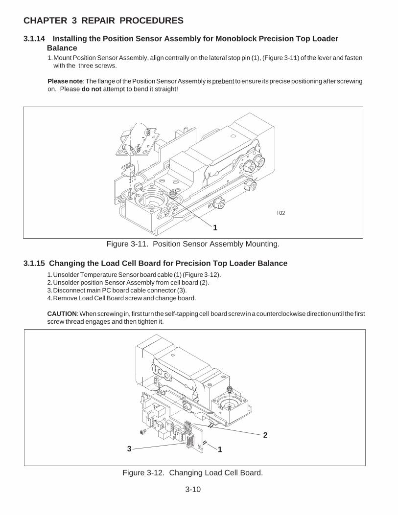
3.1.14 Installing the Position Sensor Assembly for Monoblock Precision Top LoaderBalance
3.1.15 Changing the Load Cell Board for Precision Top Loader Balance1.Unsolder Temperature Sensor board cable (1) (Figure 3-12).2.Unsolder position Sensor Assembly from cell board (2).3.Disconnect main PC board cable connector (3).4.Remove Load Cell Board screw and change board.
CAUTION: When screwing in, first turn the self-tapping cell board screw in a counterclockwise direction until the firstscrew thread engages and then tighten it.
210
1
2
3
Figure 3-12. Changing Load Cell Board.
102
1
Figure 3-11. Position Sensor Assembly Mounting.
1.Mount Position Sensor Assembly, align centrally on the lateral stop pin (1), (Figure 3-11) of the lever and fastenwith the three screws.
Please note: The flange of the Position Sensor Assembly is prebent to ensure its precise positioning after screwingon. Please do not attempt to bend it straight!

3-11
CHAPTER 3 REPAIR PROCEDURES
108
106
1.Remove four screws which secure the overloadprotection to the Monoblock. See Figure 5-5.
2.Unscrew fastener screws at formed chassis andremove Monoblock with lever from formed chas-sis. Some Monoblocks have 4 screws.
Note:Hold Monoblock only at the front next to formedchassis or at the rear.
3.Unscrew and remove three fastener screws (4) ofthe Position Sensor assembly. (See Figure 3-15).
4.Hold Contact Board (1) to ensure the fine coilwires cannot tear off, then remove Screw (2),Figure 3-14.
5.Remove Contact Board from holder and screwonto Lever (3), Figure 3-14.
6.Remove one screw (T8) attaching TemperatureBoard to underside of Monoblock magnet as-sembly and remove Temperature Board from themagnet assembly.
7.Insert the centering pins (1Aand 1B) from theservice tool set in the holes provided. See Figure3-15.
NOTE: A screw may be installed in the hole (1A), thisis additional overload protection. Turn it 1/4 turn andremove it.
8.Remove screw (4) from Load Cell Board andremove Load Cell Board Temperature BoardAssembly and Position Sensor Assembly.
9.Carefully undo Nuts (2) in the direction shown bythe arrow while holding the SCREW HEADS toprevent movement.
CAUTION:Load Force Coil Lever only in the direction shown bythe arrow to ensure the Flexible Bearings are notcompressed.
10. Note the position of the Vertical AdjustmentScrew (3). Turn Vertical Adjustment Screw sothat the Lever can be withdrawn.
11. Take out Centering Pin (1A) and (1B).
12. Carefully withdraw Force Coil Lever.
1B
3.1.16 Removing the Force Coil Lever Assembly from Monoblock in Precision Top Loader
Figure 3-13. Monoblock Assembly.
110
FORMED CHASSIS
Figure 3-14. Contact Board Removal.
41
3
2
1A
2
3
Figure 3-15. Force Coil Lever Removal.
4

3-12
CHAPTER 3 REPAIR PROCEDURES
1.Place Force Coil Lever assembly in the des-ignated position; check whether the alumi-num sleeves are correctly positioned. SeeFigure 3-16.
2.Turn back vertical adjustment screw (3) tothe original position. (See Figure 3-16).
3.Insert centring pins in the holes provided.
4.Insert the Force Coil Lever assembly fas-tener screws and carefully tighten in the direction shown by the arrow (2.5 Nm) secur-ing the NUTS to prevent movement. Ensurethat the Force Coil Lever remains in themiddle at the front.
CAUTION:Load lever only in the direction shown by thearrow to ensure the flexible bearings are notcompressed!
5.Attach Load Cell Board TemperatureSensor Board and Position Sensor Assem-bly and tighten screws.
6.Hold contact board to ensure the fine coilwires can not tear off. Then, as described inparagraph 3.1.16, remove the screw (2) fromthe lever and screw to holder. (See Figure 3-14).
7.Take out centering pins.
8.Screw Monoblock to formed chassis. Ensuretop edge of formed chassis is flush with thetop of the Monovblock. See Figure 3-17.
9.Mount overload protection on the Monoblock.
1072
1
3.1.17 Installing the Force Coil Lever Assembly in Monoblock for Precision Top LoaderBalance
109
Figure 3-16. Force Coil Lever Installation.
Figure 3-17. Monoblock Mounting.
3

3-13
CHAPTER 3 REPAIR PROCEDURES
3.1.18 Vertical Stop Adjustment for Monoblock in Precision Top Loader Balance
NoteNoteNoteNoteNote:If the Position Sensor Assembly is changed, it may benecessary to readjust the vertical stop.
Adjusting Vertical Stop
1.Attach voltmeter to 2 pin connector located atthe top left corner of the Load Cell Board.Apply power and turn on. Note voltage value.
2.Push down on overload protection until Leveris at the top of the vertical stop and thenrelease overload protection. Voltage valueshould be equal and opposite.
3.If the two voltage values either side of zeroare not of the same magnitude but, e.g. +2Volts and -1.6 Volts, the vertical stop must beadjusted until the values are symmetrical.Voltage range: ±1.8 ... 2.5 Volts.Asymmetry: max. 0.2 Volts.
4.To adjust vertical stop, turn vertical adjust-ment screw ( Figure 3-15, item 3) and repeatstep 2 until readings are symetrical.
101
Figure 3-18. Position Sensor Connections.

3-14
CHAPTER 3 REPAIR PROCEDURES
3.1.19 Monoblock Load Cell Removal from High Capacity Top Loader BalanceRefer to Figure 5-6 in Chapter 5 for location of components called out in this procedure and Figure 3-19. To remove theMonoblock Load Cell, proceed as follows:
1.With the balance turned OFF and unplugged, remove the Pan (1).
2.Remove four Pan Mounts (2).
3.Remove four Cover Housing Screws (3) which secures the Housing Cover (4) to Base (19).
4.Loosen the four Screws (17) which secures the Overload Protection (18) from Base (19).
5.Carefully lift the Overload Protection up from the Weigh Assembly (20) and out of the Base (19).
6.Disconnect the Coil Cable Connector (8) and the Cell Cable Connector (9) from the Main PCB (6).
7.Remove the two Protective Plate Screws (5) holding the Main PCB (6) and Power Supply PCB (7).
8.Carefully lift both PC boards upwards and disconnect Connector PCB Cable (10) from the Power Supply PCB(7).
9.Remove the Cable Guide (26) from inside of the Base (19).
10.Turn the Balance on it's side exposing the bottom and while holding the Weigh Assembly (20) inside of the Base (19), then, remove the three Base Screws (12) from the Base (19).
11. Remove the Weigh Assembly (20) from the Base (19).
To remove the Monoblock (23) from the Weigh Assembly (20), continue as follows:
12. Loosen the four Hex Head Screws (22) (7.5 mm) on the Weigh Assembly (20). These screws secure theWeigh Assembly to the Monoblock (23).
13. Loosen the four Screws (24) which secures the U-Block (25) to the Monoblock (23).
14. Remove the Monoblock (23).
Figure 3-19. Calibration Motor Removal.
3.1.20 Calibration Motor Removal from High Capacity Top Loader BalanceRefer to Figure 5-6 in Chapter 5 for location of components called out in this procedure and Figure 3-19. To remove thecalibration motor, proceed as follows:
1.Perform procedure as described in paragraph3.1.19 and remove the Monoblock (23) and PCboards. CAUTION
Remove Monoblock carefully so that the two calibra-tion weight spindles are not subject to stress and nevertouch anything during removal. Careless removalcould damage the calibration mechanism. Hold theMonoblock only right at the front or the back by thesection fastening.
2.Remove two screws (6) which secure theCalibration Weight Holders (1) both sides.and remove Calibration Weights Holders
3.Remove two Calibration weights (2).
4 Remove the Motor Cable (38) (See Figure 5-6) from Internal Calibration Motor Board (5).Cable may have to be redressed behind PCboard when reassembling.
1
2
3
4
5
6
3-15
CHAPTER 3 REPAIR PROCEDURES
3.1.20 Calibration Motor Removal from High Capacity Top Loader Balance (Cont.)
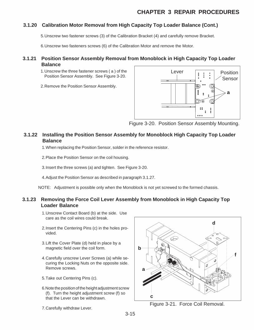
Figure 3-20. Position Sensor Assembly Mounting.
Figure 3-21. Force Coil Removal.
3.1.22 Installing the Position Sensor Assembly for Monoblock High Capacity Top LoaderBalance1.When replacing the Position Sensor, solder in the reference resistor.
2.Place the Position Sensor on the coil housing.
3.Insert the three screws (a) and tighten. See Figure 3-20.
4.Adjust the Position Sensor as described in paragraph 3.1.27.
NOTE: Adjustment is possible only when the Monoblock is not yet screwed to the formed chassis.
3.1.23 Removing the Force Coil Lever Assembly from Monoblock in High Capacity TopLoader Balance1.Unscrew Contact Board (b) at the side. Use
care as the coil wires could break.
2.Insert the Centering Pins (c) in the holes pro-vided.
3.Lift the Cover Plate (d) held in place by amagnetic field over the coil form.
4.Carefully unscrew Lever Screws (a) while se-curing the Locking Nuts on the opposite side.Remove screws.
5.Take out Centering Pins (c).
6.Note the position of the height adjustment screw(f). Turn the height adjustment screw (f) sothat the Lever can be withdrawn.
7.Carefully withdraw Lever.
a
Lever
b
a
c
d
f
Position Sensor
5.Unscrew two fastener screws (3) of the Calibration Bracket (4) and carefully remove Bracket.
6.Unscrew two fasteners screws (6) of the Calibration Motor and remove the Motor.
3.1.21 Position Sensor Assembly Removal from Monoblock in High Capacity Top LoaderBalance1.Unscrew the three fastener screws ( a ) of the
Position Sensor Assembly. See Figure 3-20.
2.Remove the Position Sensor Assembly.

3-16
CHAPTER 3 REPAIR PROCEDURES
3.1.24 Installing the Force Coil Lever Assembly in Monoblock for High Capacity TopLoader Balance
Figure 3-22. Force Coil Lever Installation.
1.Place Lever in designated position: check thatthe aluminum sleeves are properly positioned.
2.Turn back height adjustment screw to originalposition.
3.Insert Centering Pins in holes provided.
4.Insert Lever fastener screws and tighten care-fully. Ensure that the Lever remains in themiddle at the front.
5.Mount Cover Plate (align at centering pin (g)).
6. Place Position Sensor on the Coil housing.
7.Insert the three screws and tighten with thenuts.
8.Adjust Position Sensor as described in 3.1.27.
3.1.25 Installing Monoblock and Assembling Position Sensor for High Capacity TopLoader Balance1.Place Monoblock and formed chassis turned
by 180 degrees on a flat and clean benchsurface.
2.Screw Monoblock to formed chassis. Ensuretop edge of formed chassis is flush with the topof the Monoblock. See Figure 3-23.
NOTE:Tightening torque: 4.0 Nm.
3.Install Calibration Motor (eccentric in top posi-tion) and Calibration Bracket. During installa-tion, ensure that there is sufficient play be-tween the eccentric of the Motor and the Cali-bration Bracket.
4.Ensure that the Calibration Motor is in the topposition, then insert Calibration weights. AlignCalibration Weight Holders parallel with theedge of the frame profile and screw firmly sothat a slight pressure causes the Holders to reston the Weights.
Figure 3-23. Installation Monoblock andPosition Sensor.
g
� �0.
5 m
m

3-17
CHAPTER 3 REPAIR PROCEDURES
3.1.26 Changing Servomotor on High Capacity Top Loader Balance
Figure 3-24. Servomotor Installation.
�
NOTE:The replacement motor is supplied without eccen-tric and without motor holder, the correspondingparts of the old motor should be used.
1.Refer to paragraph 3.1.20 and remove Servomo-tor.
2.Detach eccentric and motor holder from the mo-tor (needed for the new motor).
3.Unscrew fastener screw of the eccentric from thenew motor.
4.Attach eccentric to new motor loosely.
5.Carefully by hand, turn motor shaft to top posi-tion.
6.Position eccentric on the motor spindle so that itis shifted one lock-in position counterclockwise(a). Screw eccentric firmly in place and thenfasten motor holder. See Figure 3-24.
7.Install motor and calibration bracket. Duringinstallation, ensure there is sufficient play be-tween the eccentric of the motor and the calibra-tion bracket.
8.Insert calibration weights. Align calibrationweight holder parallel with the edge of theframe profile and screw firmly so that a slightpressure causes the holders to rest on theweights.
TOP POSITION

3-18
CHAPTER 3 REPAIR PROCEDURES
3.1.27 Vertical Stop Adjustment for Monoblock in High Capacity Top Loader Balance
NoteNoteNoteNoteNote:The Position Sensor can be aligned by eye with themounting holes.- If the Sensor Board has been replaced, it may be necessary to adjust the vertical stop.- The vertical stop setting is the reference for the lever height (horizontal position).
Preparation1.The measuring cell remains in the balance
housing.
2. The ribbon cable from the Position Sensorassembly is plugged into the Main PC board,the coil cable remains disconnected.
3. Attach voltmeter (DC range) to pin 2 connectorlocated at the top left corner of the PositionSensor assembly.
4.Turn on the balance.
Setting vertical stop
1.Note down 1st voltage as soon as the balancehas been switched on, here the lever is at thebottom of the vertical stop.
2.Determine 2nd voltage value by carefully rais-ing lever with thumb and forefinger until it is atthe top of the vertical stop. Note down thevalue.
3.If the two voltage values and are not the same,(+ or - 1.5 ...2V, difference max. 0.1V), thevoltage must be set by adjusting the verticalstop.
4.To adjust the vertical stop, turn the verticaladjustment screw and repeat steps 1 and 2until the readings are within specifications(step 3).
Figure 3-25. Position Sensor Connections.

3-19
CHAPTER 3 REPAIR PROCEDURES
3.2 REPLACEMENT OF MAJOR COMPONENTSWhen using this section of the Service Manual, you will find it necessary to refer to other sections. References are madeto the Exploded Views which are located and identified in Chapter 5, Drawings and Parts Lists.
The decision to replace any component should only be made after thoroughly diagnosing the problem.
If, after the replacement of any component, the balance is still nonfunctional and no other information on the subject isavailable in the manual, contact:
Ohaus Corporation19A Chapin RoadP.O. Box 2033Pine Brook, NJ 07058-2033 USATel: 973-377-9000Fax: 973-593-0359
In the United States call toll free, 800-526-0659 between 8:00 a.m. and 5:30 p.m. EST.
3.2.1 Analytical Balances Main Printed Circuit Board (PCB)See Figure 5-2 for steps 1 through 4.
1.With the balance turned OFF and unplugged, open the Draft Shield door and remove the Pan (5).
2.Remove Cover Plate (6).
3.Inside of the Draft shield, remove two Screws (2) and Lockswitch Cover Seal (1).
4.Carefully lift the Draft Shield from the balance Base and set aside.
See Figure 5-3 for remaining steps.
5.Remove two Screws (3) which secure Shield (4) in place.
6.Remove Shield (4) from the balance.
7.Remove the two Screws (3) on top of the PC Board (11).
8.Remove the Hex Screws (14) and Washers (25) at the rear of the balance which secure the connectors onthe PC Board (11).
9.Disconnect the two cable connectors from the Load Cell going to J3 and J6 on the PC board as shown onFigure 5-3.The Load Cell (9). If internal calibration option is installed, disconnect cable to J4.
10. Carefully lift the PC Board (11) from the Base (18) there is a small cable from the Sensor Board which shouldalso be disconnected from the PC Board (not shown on Figure 5-3).

3-20
CHAPTER 3 REPAIR PROCEDURES
3.2.1 Analytical Balances Main Printed Circuit Board (PCB) (Cont.)
CAUTION
WHEN HANDLING THE P.C. BOARD, HANDLE BY EDGES ONLY!DO NOT TOUCH FOIL SIDE OF BOARD. STATIC DISCHARGE MAYDAMAGE SOME COMPONENTS.
11. Switch the following components from the defective Main PC Board to the replacement:
U5 EEPROMU10 - ICU11 - PSD
12. Install the replacement PC Board.
13. Connect the two cable connectors from the Analytical Load Cell (9) to the Main PC Board edge connectorsJ3, J6 and the Sensor Cable. The Sensor Board Cable is located at the rear of the balance and may interferewith the operation of the balance if it is not positioned away from the Load Cell. Dress the cables and makesure that the cables do not interfere with the Load Cell. If internal calibration option is installed, connectcable to J4.
14. Reinstall the PC Board and secure with two screws (3).
15. Install the Hex Screws (14) and Washers (25) at the rear of the balance which secure the connectors onthe PC Board (11).
16. Install the Shield (4) back on the balance and secure with two Screws (3) (Figure 5-3).
17. Install the Draft Shield and secure with two Screws (2) making sure Lockswitch Cover Seal (1) (Figure 5-2) is in place.
18. Replace the Cover Plate (6) and Pan (5) inside of the Draft Shield (Figure 5-2).
19. Connect the AC Adapter to an outlet and the Balance. Turn the balance ON.
20. Allow the balance to warm up for at least one hour.
21. If the balance appears to be functional, refer to paragraph 4.1 and retest the balance.
22. If the balance does not appear to function properly and the Main PC Board is being replaced in an effort toisolate the problem, the problem may still be in the Load Cell.

3-21
CHAPTER 3 REPAIR PROCEDURES
3.2.2 Analytical Balance - Position Sensor PC BoardWhen the Position Sensor PC Board (51C) (See Figure 5-4) has been determined that it is defective and requires replacement,proceed as follows:
1.Remove power from the balance.
2.Proceed to paragraph 3.1.1 Load Cell Removal and remove the Load Cell (51)from the balance.
3.With the Load Cell (51) out of the Base (18), position the Load Cell with the Sensor board facing towards you.
4.Mark the position of Sensor Bracket on Transducer Base. Unsolder precision resistor and cable assembly (SeeFigure 3-1). Remove the 2 Hex head screws which secure Sensor PC board Bracket to Load Cell Base andremove Sensor PCB assembly.
5.Install the new Sensor PC Board in the reverse manner from which it was removed. Ensure assemblyis mounted in marked position (step 4) and Ratio Beam does not touch the Sensor PC Board AssemblyBracket.
6.Proceed to paragraph 3.1.2 Load Cell Replacement and install the Load Cell back in to the balance.Perform the Up/Down Adjustment, paragraph 3.1.3 or 3.1.4.
3.2.3 Precision Top Loader Balances Main Printed Circuit Board (PCB)The circuitry used on the Main PCB is very complex. Troubleshooting the Main PCB requires an Oscilloscope, DVM, handtools, and the services of a trained electronics technician. In an effort to keep service costs down, it is suggested that ifthe Main PCB is suspected of being faulty, it should be replaced to verify the defect. In the case of common power supplyproblems, conventional troubleshooting techniques should be employed.
Refer to Figures 5-1 and 5-3 in Chapter 5 for location of components called out in this procedure.
See Figure 5-1 for steps 1 through 5.
1.With the balance turned OFF and unplugged, remove the Pan (1).
2.Remove Wind Shield (2).
3.Remove the four Corner Spacers (5).
4.Remove two Screws (3) and Lockswitch Cover Seal (4).
5.Remove the Cover (6) from the Base.

3-22
CHAPTER 3 REPAIR PROCEDURES
3.2.3 Precision Top Loader Balances Main Printed Circuit Board (PCB) (Cont.)See Figure 5-3 for remaining steps.
6.Remove the two Hex Screws (1) from the Subplatform (2).
7.Remove the Subplatform (2).
8.Remove two Screws (3) which secure Shield (4) in place.
9.Remove Shield (4) from the balance.
10. Remove the Hex Screws (14) and Washers (25) at the rear of the balance which secure the connectors onthe PC Board (11).
11. Disconnect the two cable connectors from the Load Cell going to J2 and J6 on the PC board as shown onFigure 5-3.The Load Cell (9). Use cable extenders. If internal calibration option is installed, disconnect cableto J4.
12. Carefully lift the PC Board (11) from the Base (18) there is a small cable from the Sensor Board which shouldalso be disconnected from the PC Board (not shown on Figure 5-3).
13. Switch the following components from the defective Main PC Board to the replacement:
U5 EEPROMU10 - ICU11 - PSD
14. Install a replacement PC Board.
15. Secure the PC Board (11) to the Base (18) with the two Screws (3).
16. Connect the two cable connectors from the Load Cell (9) to the Main PC Board edge connectorsJ2, J6 and the Sensor Cable. The Sensor Board Cable is located at the rear of the balance and may interferewith the operation of the balance if it is not positioned away from the Load Cell. Dress the cables and makesure that the cables do not interfere with the Load Cell. If internal calibration option is installed, connectcable to J4.
17. Install the Hex Screws (14) and Washers (25) at the rear of the balance into the connectors.
18. Install the Shield (4) back on the balance and secure with two Screws (3) (Figure 5-3).
19. Install the Subplatform (2) and secure with two Screws (1).
20. Replace the Cover (14) and and secure with two Screws (2) making sure that the LockswitchCover Seal is in place (Figure 5-1).
21. Replace the four Corner Spacers (13) with the open ends facing out.
22.Replace the Pan (5) and Windshield (12).
3-23
CHAPTER 3 REPAIR PROCEDURES
3.2.4 High Capacity Top Loader Balances Main Printed Circuit Board (PCB) and PowerSupply ( PCB)
Refer to Figure 5-6 in Chapter 5 for location of components called out in this procedure. There are two printed circuit boards;one is the Main PCB and the other is a Power Supply PCB. To remove the boards, proceed as follows:
1.With the balance turned OFF and unplugged, remove the Pan (1).
2.Remove four Pan Mounts (2).
3.Remove three Cover Housing Screws (3) and one screw (37) which secures the Housing Cover (4) to Base(19).
4.Disconnect the Coil Cable Connector (8), the Internal Calibration Cable (38) (if supplied) and the Cell CableConnector (9) from the Main PCB (6).
5.Remove the two Protective Plate Screws (5) holding the Main PCB (6) and Power Supply PCB (7).
6.Carefully lift both PC boards upwards and disconnect Connector PCB Cable (10) from the Power Supply PCB(7).
7.To separate the PC boards, diconnect the short Main PCB Cable (11) from the Main PCB (6).
8.If the Main PCB is being replaced, the following components must be removed from the defective PCB andinstalled on the replacement PCB.
IC1 EPROMIC16 EPROM
If the Power Supply PCB is being replaced, replace the following components:IC8 EPROMIC3 EEPROMIC12 IC
NOTE: When replacing the PC boards, you will notice two grooves in the Base (19). The PC boards must beproperly seated in these grooves when being replaced.
9.Connect Connector PCB Cable (10) located in the Base (19) to the Power Supply PCB (7).
10. Facing the front of the balance, insert the Power Supply PCB (7) into the slot closest to the left side of thebalance. The holes on the metal shield on the Power Supply PCB (7) should line up with the mounting holeson the Base (19).
11. Still facing the front of the balance, insert the replacement Main PCB in the remaining groove in the Base (19).Make sure the short Main PCB Cable (11) from the Power Supply PCB (7) passes through the access holeon the Main PCB. The holes on the shield on the Main PCB should line up over the holes on the Power SupplyPCB.
12. Install the two Protective Plate Screws (5) holding the Main PCB (6) and Power Supply PCB (7).
13. Connect the Coil Cable Connector (8), Internal Calibration Assembly Cable (38) (if supplied) and the CellCable Connector (9) to the Main PCB (6).
14. Replace three Cover Housing Screws (3) and one screw (37) which secures the Housing Cover (4) to Base(19).
15. Install four Pan Mounts (2).
16. Install the Pan (1) and apply power to the balance.

3-24
CHAPTER 3 REPAIR PROCEDURES
3.2.5 High Capacity Top Loader Balances Connector Printed Circuit Board (PCB)Refer to Figure 5-6 in Chapter 5 for location of components called out in this procedure. The Connector PCB is locatedon the left side of the balance. To remove the board, proceed as follows:
1.Unplug the balance.
2.Remove Platform(1). and turn the balance so it stands on the rear portion.
3.Remove the two screws (12) holding the Connector Plate (13) and Connector PCB (14).
4.Remove the four Hex Nut screws (15) which secures the Connector Plate (13) to the Connector PCB (14).
5.Disconnect Connector Board Cable (10) from Connector PCB (14).
6.Disconnect Display Module Cable (16) from the Connector PCB.
7.Replace Connector PCB and connect Display Module cable (16).
8.Connect Connector Board Cable (10) to the Connector PCB.
9.Install the four Hex Nut screws (15) which secures the Connector Plate (13) to the Connector PCB (14).
10. Position the Connector Plate (13) over the holes on the side of the balance and install the two screws (12).
11. Turn the balance in it's proper operating position and install the pan (1).
12. Apply power to the balance.
3.2.6 Removing the Display Module on Explorer Precision Top Loader Balances(See Figure 3-26)
1.Remove power from the balance.
2.Underneath the front of the balance, press the two tabs (1) towards the rear of the balance, this will releasethe display.
3.Carefully lift the display (2) up from the balance and swing towards the rear. You will notice a grounding strapwhich is screwed into the base of the balance.
4.Remove screw (3) and flat washer (4) from the grounding strap.
5.Carefully unplug the Main PCB Assembly Ribbon Cable (5) from the connector on the Display PCB Assemblyof the display module. Refer to paragraph 3.2.8 for Display PCB replacement.
CAUTION:BE CAREFUL NOT TO PULL THE RIBBON CABLE OUT OF THE CONNECTOR ON THE MAIN PCB ASSEMBLY INSIDE THE BALANCE.

3-25
CHAPTER 3 REPAIR PROCEDURES
3.2.6 Removing the Display Module on Explorer Precision Top Loader Balances (Cont.)
Figure 3-26. Display Removal/Installation for Explorer Precision Top Loader Balance.
3.2.7 Removing the Display Module on Explorer High Capacity Top Loader Balances(See Figure 3-20)
1.Remove power from the balance.
2.Remove Pan (1) and place balance with bottom facing you.
3.Remove two screws from underneath the display.
4.Underneath the front of the balance, press the two tabs (1) towards the rear of the balance, this will releasethe display.
5.Carefully lift the display (2) up from the balance and swing towards the rear. You will notice a grounding strapwhich is screwed into the base of the balance.
6.Remove screw (3) and flat washer (4) from the grounding strap.
7.Carefully unplug the Main PCB Assembly Ribbon Cable (5) from the connector on the Display PCB Assemblyof the display module.
>O/T<
>O/T<3
2
1
4
5
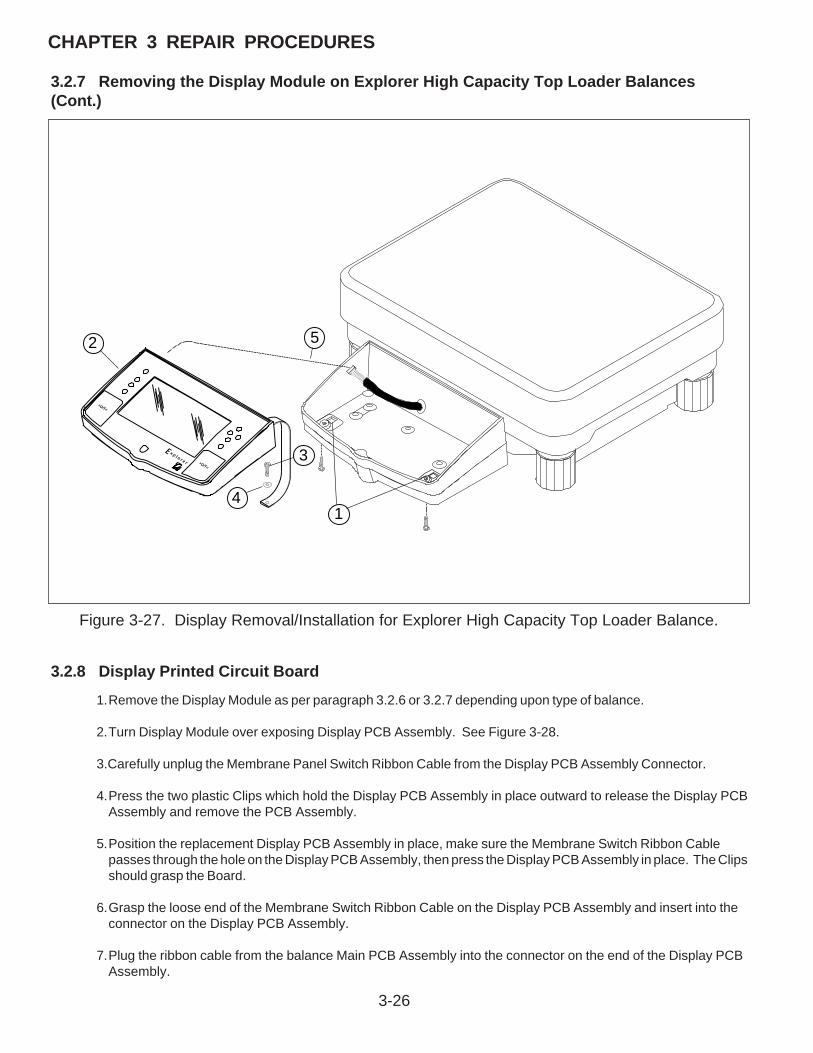
3-26
CHAPTER 3 REPAIR PROCEDURES
3.2.7 Removing the Display Module on Explorer High Capacity Top Loader Balances(Cont.)
Figure 3-27. Display Removal/Installation for Explorer High Capacity Top Loader Balance.
3.2.8 Display Printed Circuit Board
>O/T<
>O/T<
1
2
3
4
5
1.Remove the Display Module as per paragraph 3.2.6 or 3.2.7 depending upon type of balance.
2.Turn Display Module over exposing Display PCB Assembly. See Figure 3-28.
3.Carefully unplug the Membrane Panel Switch Ribbon Cable from the Display PCB Assembly Connector.
4.Press the two plastic Clips which hold the Display PCB Assembly in place outward to release the Display PCBAssembly and remove the PCB Assembly.
5.Position the replacement Display PCB Assembly in place, make sure the Membrane Switch Ribbon Cablepasses through the hole on the Display PCB Assembly, then press the Display PCB Assembly in place. The Clipsshould grasp the Board.
6.Grasp the loose end of the Membrane Switch Ribbon Cable on the Display PCB Assembly and insert into theconnector on the Display PCB Assembly.
7.Plug the ribbon cable from the balance Main PCB Assembly into the connector on the end of the Display PCBAssembly.

3-27
CHAPTER 3 REPAIR PROCEDURES
3.2.8 Display Printed Circuit Board (Cont.)
8.Secure the grounding strap using the hardware previously removed.
9.Carefully position the display flush with the top of the balance and press into position. The tabs underneaththe balance should lock into place.
10. Reconnect power to the balance.
GROUNDING STRAP
MOUNTING CLIP MOUNTING CLIPBOTTOM OF DISPLAY PCB ASSEMBLY
COVER
RIBBON CABLE CONNECTOR END
COVER CLIP COVER CLIP
LOCATING PIN
INSERT RIBBON CABLE FROM MAIN PCB ASSEMBLY
MEMBRANE SWITCH RIBBON CABLE
Figure 3-28. Rear View of the Display PCB Assembly.
3.2.9 Membrane Switch Replacement
1.Follow the procedure in paragraph 3.2.6 or 3.2.7 and remove the display module from the balance.
2.Remove the membrane switch ribbon cable from the PC Board, see Figure 3-28.
3.On the front of the display, carefully remove the existing membrane switch from the display panel. Lift themembrane switch off starting at one corner.
4.Remove all adhesive residue from the display panel.
5.At the back of the new membrane switch, remove the protective covering from the window area first.
6.Remove the adhesive backing from the membrane switch. Be very careful at this point. You want to make surethe membrane switch is properly placed as you cannot remove it to reposition it on the display panel.
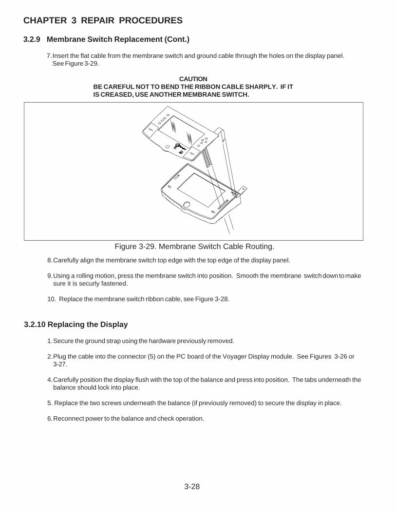
3-28
CHAPTER 3 REPAIR PROCEDURES
3.2.9 Membrane Switch Replacement (Cont.)
7.Insert the flat cable from the membrane switch and ground cable through the holes on the display panel.See Figure 3-29.
CAUTIONBE CAREFUL NOT TO BEND THE RIBBON CABLE SHARPLY. IF ITIS CREASED, USE ANOTHER MEMBRANE SWITCH.
8.Carefully align the membrane switch top edge with the top edge of the display panel.
9.Using a rolling motion, press the membrane switch into position. Smooth the membrane switch down to makesure it is securly fastened.
10. Replace the membrane switch ribbon cable, see Figure 3-28.
3.2.10 Replacing the Display
1.Secure the ground strap using the hardware previously removed.
2.Plug the cable into the connector (5) on the PC board of the Voyager Display module. See Figures 3-26 or3-27.
4.Carefully position the display flush with the top of the balance and press into position. The tabs underneath thebalance should lock into place.
5. Replace the two screws underneath the balance (if previously removed) to secure the display in place.
6.Reconnect power to the balance and check operation.
>O/T<
>O/T<
Figure 3-29. Membrane Switch Cable Routing.

3-29
CHAPTER 3 REPAIR PROCEDURES
3.2.11 Removing the Display Module Voyager and Explorer Pro Models
(See Figure 3-23)1.Remove power from the balance.
2.Underneath the front of the balance, press the two tabs (1) towards the rear of the balance, this will releasethe display.
3.Carefully lift the display (2) up from the balance and swing towards the rear. You will notice a grounding strapwhich is screwed into the base of the balance.
4.Remove screw (3) and flat washer (4) from the grounding strap.
5.Carefully unplug the Main PCB Assembly Ribbon Cable (5) from the connector on the Display PCB Assemblyof the display module.
CAUTION:Be careful not to pull the RIBBON cable out of the connector on themain PCb assembly inside the balance.
Figure 3-30. Display Removal/Installation.
>O/T<
>O/T<3
2
1
4
5

3-30
CHAPTER 3 REPAIR PROCEDURES
3.2.12 Display PCB/LCD Assembly ReplacementThis procedure describes the replacement of either the PCB Assembly or LCD Assembly.
1.Remove the Display module as per paragraph 3.2.11.
2.Turn Display Module over exposing Display PCB Assembly. See Figures 3-31 and 5-9.
3.Carefully unplug the Membrane Panel Switch Ribbon Cable from the Display PCB Assembly Connector.
4.Remove the four, 4 Mounting Screws from Display PCB Assembly and remove the Display PCB Assembly. TheLCD Assembly Board is attached to the Display PCB Assembly with four screws. See Figure 5-9.
5.Turn the Display PCB Assembly over and remove the four screws which mount the LCD Assembly Board to theDisplay PCB. Both boards should now be separated. Disconnect the Bulb Connector cable from the DisplayPCB Assembly. Either board can now be replaced.
See Appendix D for Bottom Board replacement.
6.See paragraph 3.2.13 for Bulb replacement. If the Bulb is not going to be replaced, continue with this procedure.
7.Assembly both boards together using the four Screws previously removed and reconnect the Bulb Connector.
8.Place the PC boards into position over the four plastic guide posts which are slotted.
9.Screw the four 4 - 40 x 3/16" Mounting Screws into the raised guides and secure both boards.
10. Grasp the loose end of the Membrane Switch Ribbon Cable and insert into the connector on the Display PCBAssembly.
11. Secure the grounding strap using the hardware previously removed.
12. Plug the ribbon cable from the balance Main PCB Assembly into the connector on the end of the Display PCBAssembly.
13. Carefully position the display flush with the top of the balance and press into position. The tabs underneaththe balance should lock into place.
14. Reconnect power to the balance.
Figure 3-31. Rear View of Display PCB Assembly.
GROUNDING STRAP
BOTTOM OF DISPLAY PCB ASSEMBLY
COVER
RIBBON CABLE CONNECTOR END
COVER CLIP COVER CLIP
MOUNTING SCREWS
INSERT RIBBON CABLE FROM MAIN PCB ASSEMBLY
MEMBRANE SWITCH RIBBON CABLE
WIRES TO BULB ON LCD ASSEMBLYBULB CONNECTOR

3-31
CHAPTER 3 REPAIR PROCEDURES
3.2.13 Bulb Replacement
This procedure describes the replacement of the Bulb on the LCD Display Assembly. See Figure 3-32.
NOTE: This procedure requires that all hardware items that are removed be saved as they are not available as spareparts.
1.Remove the Display module as per paragraph 3.2.11.
2. Proceed with paragraph 3.2.12 and perform steps 1 through 6.
3.Remove the two Plastic Push-In Fasteners from the Bracket on the LCD Assembly. These can be removedeasily by turning the LCD Assembly over and pushing the on center portion of the Fasteners. Turn the LCDAssembly back over and remove both pieces of the Fastener.
4.Remove the Bracket from the LCD Assembly.
5.Slide the Diffusion Panel out from the LCD Assembly.
6.The Bulb has two End Caps, slide both End Caps off of the Bulb. See Figure 3-32.
7.Using a low wattage soldering iron, unsolder wire at each end of the Bulb.
8.Slide the Bulb out from the Diffusion Panel.
9.Insert the replacement Bulb in the Diffusion Panel.
10. Solder the wires back to the Bulb, and replace the End caps.
11. Reassemble the Diffusion Panel back into the LCD Display Assembly.
12. Continue with step 7 of paragraph 3.2.12 and reassemble the LCD Assembly and PCB Assembly.

3-32
CHAPTER 3 REPAIR PROCEDURES
Figure 3-32. LCD Assembly Bulb Replacement.
BULB
END CAP
DIFFUSER PANEL
BRACKET
LCD ASSEMBLY
PLASTIC PUSH IN FASTENER
BULB WIRE
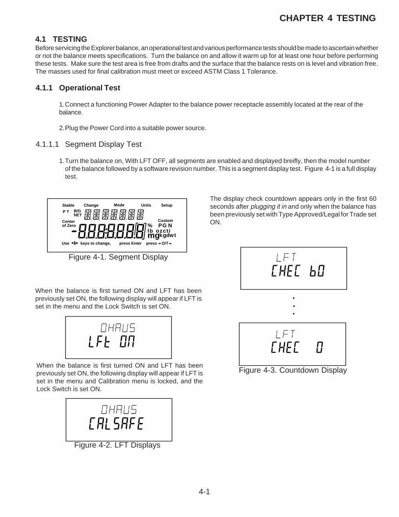
4-1
CHAPTER 4 TESTING
4.1 TESTINGBefore servicing the Explorer balance, an operational test and various performance tests should be made to ascertain whetheror not the balance meets specifications. Turn the balance on and allow it warm up for at least one hour before performingthese tests. Make sure the test area is free from drafts and the surface that the balance rests on is level and vibration free.The masses used for final calibration must meet or exceed ASTM Class 1 Tolerance.
4.1.1 Operational Test
1.Connect a functioning Power Adapter to the balance power receptacle assembly located at the rear of thebalance.
2.Plug the Power Cord into a suitable power source.
4.1.1.1 Segment Display Test
1.Turn the balance on, With LFT OFF, all segments are enabled and displayed breifly, then the model numberof the balance followed by a software revision number. This is a segment display test. Figure 4-1 is a full displaytest.
Stable Mode Units Setup
Custom
Use keys to change,
B/GNET
P T
Centerof Zero
press - O/T -
% PG Nlb ozctimg
press Enter
kgdwt
Change
Figure 4-1. Segment Display
When the balance is first turned ON and LFT has beenpreviously set ON, the following display will appear if LFT isset in the menu and the Lock Switch is set ON.
When the balance is first turned ON and LFT has beenpreviously set ON, the following display will appear if LFT isset in the menu and Calibration menu is locked, and theLock Switch is set ON.
Figure 4-2. LFT Displays
Figure 4-3. Countdown Display
The display check countdown appears only in the first 60seconds after plugging it in and only when the balance hasbeen previously set with Type Approved/Legal for Trade setON.
•
••

4-2
CHAPTER 4 TESTING
4.2 PERFORMANCE TESTS ALL BALANCESAccurate performance of the Explorer balance is determined by a series of four performance tests. The displayed readingsare compared with the tolerances listed in Table 4-1. Tolerance values are expressed in counts. A one count change isequal to the last digit shown on the balance display.
TABLE 4-1. TYPES OF PERFORMANCE TESTS
PERFORMANCE TEST ANALYTICAL TOP LOADER TOLERANCE TOLERANCE 210, 410/100, 610, 4100, 6100, 8100 12000, 22000, 32000
2100, 4100/1000Repeatability + 1 Count + 1 Count + 1 Count + 1 Count
Off Center Load + 3 Counts + 2 Counts + 1 Count + 2 Counts
Linearity + 2 Counts + 2 Counts + 1 Count + 4 Counts
The following performance tests are used to evaluate the balance operation before and after repairs. Each balance testedmust meet the requirements specified in each test as well as the specifications listed in Table 1-2 depending upon the model.Before proceeding with the following tests, all the procedures starting with paragraph 4.1 must have been accomplished onthe Balance first.
4.2.1Precision/Repeatability TestPrecision is a term used in balance specifications which means the standard deviation of a set of similar weight readings.
To conduct a Repeatability Test, proceed as follows:
1.With the balance calibrated, place a mass on the Pan equal to the capacity of the balance. Record the reading.
2.Remove the mass from the Pan, the balance should return to 0g. Record the reading.
3.Repeat steps 1 and 2 ten more times. Subtract the lowest from the highest reading to determine the differ-ence. Maximum allowable difference is as listed in Table 4-1.
4.If the balance does not meet specifications, refer to Table 2-1 to determine the problem.
4.2.2 Off-Center Load TestThe Off-Center Load Test is used to determine whether displayed weight values will be affected by moving the sample todifferent areas of the Pan.
Test for Analytical BalancesPlace 1/2 of the balance capacity in the center of the Pan (1). Press the >O/T< button to return the reading to zero. Movethe mass halfway (between the center and the edge) to the front of the Pan. Note any differences in the displayed weightreading. Repeat this test for the back, left, and right positions. Maximum allowable change is per Table 4-3 for each of thelisted balances four positions. To correct an off-center load error, proceed as follows:
Adjustment for Analytical BalancesThis adjustment requires that the balance be partially disassembled to gain access to the Load Cell for adjustments. Referto Figures 5-2 and 5-3 in Chapter 5 for location of components called out in this procedure. Cable extenders are requiredfor the Main PC Board which must be operational for Load Cell adjustments.
See Figure 5-2 for steps 1 through 4.
1.With the balance turned OFF and unplugged, open the Draft Shield door and remove the Pan (5).
2.Remove Cover Plate (6).
3.Inside of the Draft shield, remove two Screws (2) and Lockswitch Cover Seal (1).
4.Carefully lift the Draft Shield from the balance Base and set aside.
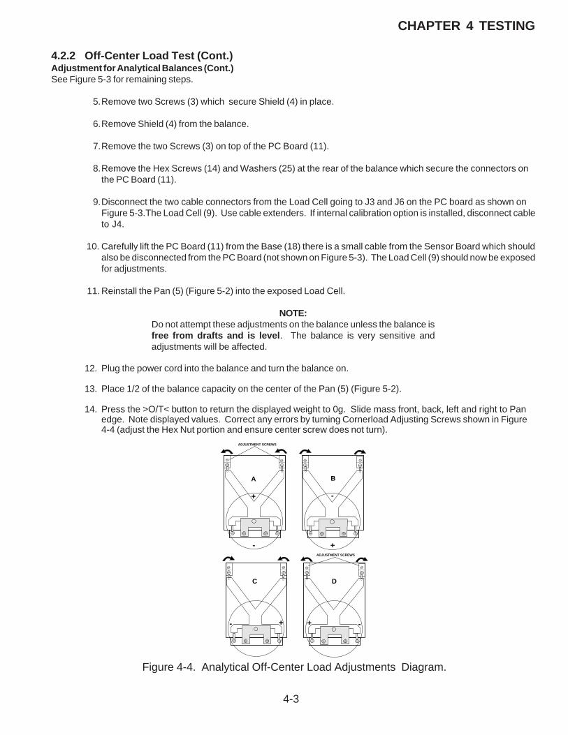
4-3
CHAPTER 4 TESTING
4.2.2 Off-Center Load Test (Cont.)Adjustment for Analytical Balances (Cont.)See Figure 5-3 for remaining steps.
5.Remove two Screws (3) which secure Shield (4) in place.
6.Remove Shield (4) from the balance.
7.Remove the two Screws (3) on top of the PC Board (11).
8.Remove the Hex Screws (14) and Washers (25) at the rear of the balance which secure the connectors onthe PC Board (11).
9.Disconnect the two cable connectors from the Load Cell going to J3 and J6 on the PC board as shown onFigure 5-3.The Load Cell (9). Use cable extenders. If internal calibration option is installed, disconnect cableto J4.
10. Carefully lift the PC Board (11) from the Base (18) there is a small cable from the Sensor Board which shouldalso be disconnected from the PC Board (not shown on Figure 5-3). The Load Cell (9) should now be exposedfor adjustments.
11. Reinstall the Pan (5) (Figure 5-2) into the exposed Load Cell.
NOTE:Do not attempt these adjustments on the balance unless the balance isfree from drafts and is level. The balance is very sensitive andadjustments will be affected.
12. Plug the power cord into the balance and turn the balance on.
13. Place 1/2 of the balance capacity on the center of the Pan (5) (Figure 5-2).
14. Press the >O/T< button to return the displayed weight to 0g. Slide mass front, back, left and right to Panedge. Note displayed values. Correct any errors by turning Cornerload Adjusting Screws shown in Figure4-4 (adjust the Hex Nut portion and ensure center screw does not turn).
C D
A B
ADJUSTMENT SCREWS
+
- +
-
- + -+
ADJUSTMENT SCREWS
Figure 4-4. Analytical Off-Center Load Adjustments Diagram.

4-4
CHAPTER 4 TESTING
15. Repeat the Off-Center Load Test.
16. Turn the balance OFF and unplug power cord.
17. Remove the Pan (5).
18. Remove cable extenders, connect the two cable connectors from the Analytical Load Cell (9) to the Main PCBoard edge connectors J3, J6 and the Sensor Cable. The Sensor Board Cable is located at the rear of thebalance and may interferewith the operation of the balance if it is not positioned away from the Load Cell.Dress the cables and make sure that the cables do not interfere with the Load Cell. If calibration option isinstalled, connect cable to J4.
19. Reinstall the PC Board and secure with two screws (3).
20. Install the Hex Screws (14) and Washers (25) at the rear of the balance which secure the connectors onthe PC Board (11).
21. Install the Shield (4) back on the balance and secure with two Screws (3) (Figure 5-3).
22. Install the Draft Shield and secure with two Screws (2) making sure Lockswitch Cover Seal (3) (Figure 5-2)is in place.
23. Replace the Cover Plate (6) and Pan (5) inside of the Draft Shield (Figure 5-2).
NOTE:If the Off-Center Load Adjustment cannot be completed, refer to thePrecision Test/Adjustment.
4.2.2 Off-Center Load Test (Cont.)Adjustment for Analytical Balances (Cont.)
Checking the Off-Center Load1.Level the balance.
2.Place test weight in the middle of the weighingpan and tare.
3.Move test weight half way to the weighing panedge and note down the print out display valueswhich differ from zero with sign (see examples).
4.Compare display values with off center loadtolerance as listed in Table 4-1.
Test for Monoblock Balances
201
-10
-2+3
+7
0
Figure 4-5. Monoblock Off-Center Load.
4-5
CHAPTER 4 TESTING
Adjustment for Monoblock used in Precision Top Loader Balances (210g to 8100g)This adjustment requires that the balance be partially disassembled to gain access to the Load Cell for adjustments. Referto Figures 5-1 and 5-3 in Chapter 5 for location of components called out in this procedure.
See Figure 5-1 for steps 1 through 5.
1.With the balance turned OFF and unplugged, remove the Pan (1).
2.If applicable, remove Wind Shield (2).
3.Remove the four Corner Spacers (5).
4. Remove two Screws (3) and Lockswitch Cover Seal (4).
5.Remove the Cover (6) from the Base.
See Figure 5-3 for remaining steps.
6.Remove the two Hex Screws (1) from the Subplatform (2).
7.Remove the Subplatform (2).
8.Remove two Screws (3) which secure Shield (4) in place.
9.Remove Shield (4) from the balance.
10.Remove two Screws (3) from the PC Board (11).
11.Remove the Hex Screws (14) and Washers (25) at the rear of the balance which secure the connectors onthe PC Board (11).
12. Disconnect the two cable connectors from the Load Cell going to J2 and J6 on the PC board as shown on Figure 5-3.The Load Cell (9). Use cable extenders for all connectors. If internal calibration option is installed, disconnect cable to J4.
1 3. Carefully lift the PC Board (11) from the Base (18) there is a small cable from the Sensor Board which should also be disconnected from the PC Board (not shown on Figure 5-3). The Load Cell (9) should now be exposed for adjustments.
4.2.2 Off-Center Load Test (Cont.)

4-6
CHAPTER 4 TESTING
Eckenlast abgleichen
��
��
��
��
���
���
Position of the test weight Filling positionwith + display
400
Viewed From Front of Balance
Adjusting the Cornerload on Precision TopLoader BalancesThe Monobloc measuring cell is not adjusted by means ofthe cornerload screws, but by removing material from its top.
This is achieved by a few strokes with a nibler file exertingslight pressure as you pull the file towards you.
CAUTION CAUTION CAUTION CAUTION CAUTION: • Do not attempt to adjust if more than 5 counts out.
• File only in positions shown in Figure 4-6.
• On completion of the adjustments, clean filing sites by removing residue with adhesive tape. See Figure 5-3 for following steps.
1.With power removed, install Pan Support (2), andweighing Pan then apply power.
2.Perform off center load test and determine error.
3.Remove Pan and Pan Support.
4.Determine associated filing position per Figure 4-10. Perform adjustment as required.
5.Repeat above steps until balance is withintolerance as per table 4-1.
6.Turn the balance OFF and remove power
7.Remove the Pan and Pan Support (2).
8.Remove cable extenders, connect the twocable connectors from the Load Cell (9) to theMain PC Board edge connectors J2, J6 and theSensor Cable. The Sensor Board Cable is lo-cated at the rear of the balance and mayinterfere with the operation of the balance if it is
not positioned away from the Load Cell. Dressthe cables and make sure that the cables donot interfere with the Load Cell. If calibrationoption is installed, connect cable to J4.
9.Reinstall the PC Board and secure with two screws (3).
10.Install the Hex Screws (14) and Washers (25) at the rear of the balance which secure the connectors on the PC Board (11).
11.Install the Shield (4) back on the balance and secure with two Screws (3) (Figure 5-3).
12.Install the Pan Support (2) and secure with two Screws (1).
13.Replace the Cover (6) and and secure with two Screws (3) making sure that the Lockswitch Cover Seal (4) is in place (Figure 5-1).
14.Replace the four corner pan Spacers (5).
15.Replace the Pan (1) and Windshield (2) if applicable.
Figure 4-6. Monoblock Adjustments.
4.2.2 Off-Center Load Test (Cont.)

4-7
CHAPTER 4 TESTING
Adjustment for Monoblock used in High Capacity Top Loader Balances (12000g to 32000g)This adjustment requires that the balance be partially disassembled to gain access to the Load Cell for adjustments. Referto Figure 5-6 in Chapter 5 for location of components called out in this procedure.
1.With the balance turned OFF and unplugged, remove the Pan (1).
2.Remove the four Pan Mounts (2).
3.Remove the three Cover Housing Screws (3) and one Flat Head Screw (37) which secure Housing Cover(4) to Base (19).
4.Remove the Housing Cover (4). The large monoblock is now visable.
Adjusting the Cornerload on High Capacity Top Loader BalancesThe Monobloc measuring cell is not adjusted by means of the cornerload screws, but by removing material from its top.
This is achieved by a few strokes with a nibler file exerting slight pressure as you pull the file towards you.
CAUTION CAUTION CAUTION CAUTION CAUTION: • Do not attempt to adjust if more than 5 counts out. If more than 5 counts, return to factory for repair.
• File only in positions shown in Figure 4-6.
• On completion of the adjustments, clean filing sites by removing residue with adhesive tape. See Figure 5-6 for following steps.
1.With power removed, temporarily install the four Pan Mounts (2), and weighing Pan (1), level the balance, thenapply power.
2.Perform off center load test and determine error.
3.Remove Pan (1).
4.Determine associated filing position per Figure 4-8. Perform adjustment as required.
5.Repeat above steps until balance is within tolerance as per table 4-1.
6.Turn the balance OFF and remove power.
7.Remove the Pan (1) and Pan Mounts (2).
8.Install the Housing Cover (4) into place on the Base (19) and secure with the three Cover Housing Screws (3)and one Flat head Screw (37).
9.Install the four Pan Mounts (2) onto the posts of the Overload Protection (18).
10.Replace the Pan (1).
4.2.2 Off-Center Load Test (Cont.)
•

4-8
CHAPTER 4 TESTING
4.2.3 Linearity TestThe Linearity test is used to determine the span and linearity of the balance throughout its operating range and is in accordancewith the specifications listed in Tables 1-2, 1-3 and 1-4. The masses used to perform this test must meet or exceed ASTMClass 1 Tolerance.
NOTE:The balance must pass the Off-Center Load test before the Linearity Testis performed.
This test is used to determine the linearity of the balance throughout its operating range.Table 4-2 lists the suggested masses to be used for checking linearity on each balance model.
TABLE 4-2. CENTER LOAD TEST MASSESANALYTICAL PRECISION TOP LOADER
CAPACITY 62g 110g 210g 210/100g 210g 410g 410/100g 610g 2100g 4100g 4100/1000g 4100g 6100g 8100g Ref. Mass 1g 1g 1g 1g/1g 1g 1g 1g 1g 1g 1g 1g 1g 1g 1g
Load 1 10g 10g 10g 10g/10g 10g 10g 10g/10g 10g 100g 1000g 1000g/10g 1000g 500g 1000g
Load 2 20g 25g 100g 20g/20g 50g 100g 50g/50g 200g 500g 1000g 1000g/100g 1000g 2000g 4000g
Load 3 40g 50g 150g 30g/30g 100g 200g 200g/75g 400g 1000g 2000g 2000g/200g 2000g 4000g 6000g
Load 4 50g 100g 200g 40g/40g 150g 400g 400g/100g 600g 2000g 4000g 4000g/500g 4000g 6000g 8000g
A 1g calibration mass is recommended for the reference mass. All masses are nominal values. HOWEVER, BE CERTAINTO USE THE SAME REFERENCE MASS THROUGHOUT THE PROCEDURE.
1. Perform a linearity calibration, see the calibration section of the instruction manual. ASTM Class 1 Masses must be used for the calibration only. The test can be performed using utility masses.
2. Place the test mass on the pan and record the weight.
3. Remove the test mass and place Load 1 on the pan.
4. Zero the balance.
5. Place the test mass on the pan and record the weight.
6. Remove the test mass and place Load 2 on the pan.
7. Zero the balance.
8. Place the test mass on the pan and record the weight.
9. Remove the test mass and place Load 3 on the pan.
10.Zero the balance.
11.Place the test mass on the pan and record the weight.
12.Remove the test mass and place Load 4 on the pan
13. Zero the balance.
14. Place the test mass on the pan and record the weight.
15. All of the recorded weights must be within the tolerance of Table 4-1.
CAPACITY 12000g 22000g 32000g
Ref. Mass 1g 1g 1g
Load 1 2000g 4000g 6000g
Load 2 4000g 8000g 12000g
Load 3 8000g 16000g 22000g
Load 4 12000g 22000g 32000g
HIGH CAPACITY TOP LOADER

4-9
CHAPTER 4 TESTING
4.2.4 RS232 Communication TestThe RS232 Interface in the Explorer balance can have its performance monitored using an external printer or computerconnected to the balance.
The RS232 Interface is a bi-directional interface which enables the balance to communicate with a printer or computerequipped with an RS232 serial port. An RS232 menu is in the balance. This menu enables various parameters such as Baudrate, Data bits, Stop Bits and Parity to be set in the balance.
1.Connect the balance to a computer that can run Hyperterminal or a similiar terminal program. Using either theAS017-09 or AS017-02 cable. Make sure the end of the cable marked balance is connected to the balance.
2.Make sure the communication parameters (Baud, Data Bits, parity, stop bits) are matched. refer to the instructionmanual.
3.Press the PRINT button on the balance.
4.The terminal program should display whatever was on the display of the balance.
5.Send an Upper case V from the terminal program to the balance.
6.The balance should respond with the software version it has installed.
7.If both tests were sucessful, the balance will communicate.

4-10
CHAPTER 4 TESTING

5-1
CHAPTER 5 DRAWINGS AND PARTS LISTS
5.1 DRAWINGS AND PARTS LISTSThis section of the manual contains exploded views for the Explorer Balances with associated parts lists.. The explodedview drawings are designed to identify the parts which can be serviced on the balance in the field. To facilitate this, thefollowing coding system is used:
When a key number is enclosed by an circle, it indicates that this part is stocked by Ohaus andcan be ordered.
When a key number is enclosed by a four sided box, it indicates that this part is NOT stocked byOhaus and cannot be ordered. The parts are shown for clarity only.
NOTE:In all cases where a part is replaced, the balance must be thoroughly checked after the replacement is made.The balance MUST meet the parameters of all applicable specifications in this manual.
If further technical information is needed, please contact:
Ohaus Corporation19A Chapin RoadP.O. Box 2033,Pine Brook, NJ 07058-2033 USATel: 973-377-9000Fax: 973-593-0359
In the United States call toll free, 800-526-0659 between 8:00 a.m. and 5:30 p.m. EST.

5-2
CHAPTER 5 DRAWINGS AND PARTS LISTS
Figure 5-1. Overall Exploded View of Precision Top Loader Balance.
>O/T<
>O/T<
3
8
7 6
1
5
1
2
10
9
11
See Figure 5-2
NOTE: Boxed items are not available for sale.

5-3
CHAPTER 5 DRAWINGS AND PARTS LISTS
5.2 PARTS LISTSThis section of the manual contains the replaceable parts for all models of the the Explorer / Voyager / Explorer Pro balances.
5.2.1 Precision Top Loader Base Parts List
TABLE 5-1. PRECISION TOP LOADER BASE PARTS LIST (See Figure 5-1)
KEY NO. PART NO. DESCRIPTION
1 11108206 Pan, 6.8" x 6.8", Explorer, Voyager, Explorer Pro
1 11108200 Pan Assy, 8" x 8", Explorer, Voyager, Explorer Pro
2 11136325 Wind Shield, Explorer, Voyager, Explorer Pro
5 11108115 Spacer, Explorer, Voyager, Explorer Pro
6 11136113 Cover, Top Loader, Explorer, Voyager, Explorer Pro
9 490202-010 Power Adapter, 100V - 120V, Explorer, Voyager, Explorer Pro
10 490203-010 Power Adapter, 220V - 240V, Explorer, Voyager, ExplorerPro Note: (Requires Line Cord)
11 76448-00 Line Cord, UK Style Plug, Explorer, Voyager, Explorer Pro
11 76199-01 Line Cord, Australian Style Plug, Explorer, Voyager, Explorer Pro
11 76198-00 Power Cord, 220V, E. European
NOTES: 1. In all cases where a part is replaced, the balance shall be thoroughlychecked after the replacement is made. The balance must meet theparameters of all applicable specifications in this manual.
2. Ohaus replacement parts warranty only applies to parts purchasedfrom Ohaus Corporation.

5-4
CHAPTER 5 DRAWINGS AND PARTS LISTS
Figure 5-2. Overall Exploded View of Analytical Balance.
1
5
6
8
>O/T<
>O/T<
9
3
4
10
13
11
18
14
16
12
17
15
7
2
NOTE: Boxed items are not available for sale.
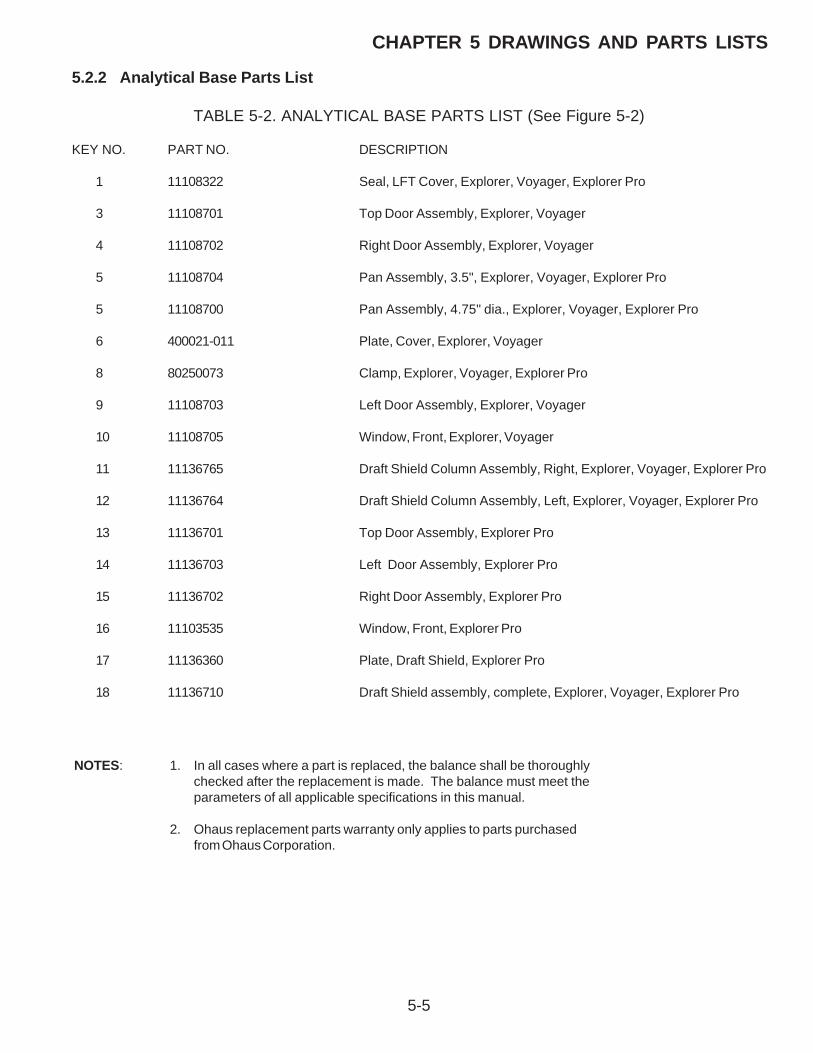
5-5
CHAPTER 5 DRAWINGS AND PARTS LISTS
5.2.2 Analytical Base Parts List
TABLE 5-2. ANALYTICAL BASE PARTS LIST (See Figure 5-2)
KEY NO. PART NO. DESCRIPTION
1 11108322 Seal, LFT Cover, Explorer, Voyager, Explorer Pro
3 11108701 Top Door Assembly, Explorer, Voyager
4 11108702 Right Door Assembly, Explorer, Voyager
5 11108704 Pan Assembly, 3.5", Explorer, Voyager, Explorer Pro
5 11108700 Pan Assembly, 4.75" dia., Explorer, Voyager, Explorer Pro
6 400021-011 Plate, Cover, Explorer, Voyager
8 80250073 Clamp, Explorer, Voyager, Explorer Pro
9 11108703 Left Door Assembly, Explorer, Voyager
10 11108705 Window, Front, Explorer, Voyager
11 11136765 Draft Shield Column Assembly, Right, Explorer, Voyager, Explorer Pro
12 11136764 Draft Shield Column Assembly, Left, Explorer, Voyager, Explorer Pro
13 11136701 Top Door Assembly, Explorer Pro
14 11136703 Left Door Assembly, Explorer Pro
15 11136702 Right Door Assembly, Explorer Pro
16 11103535 Window, Front, Explorer Pro
17 11136360 Plate, Draft Shield, Explorer Pro
18 11136710 Draft Shield assembly, complete, Explorer, Voyager, Explorer Pro
NOTES: 1. In all cases where a part is replaced, the balance shall be thoroughlychecked after the replacement is made. The balance must meet theparameters of all applicable specifications in this manual.
2. Ohaus replacement parts warranty only applies to parts purchasedfrom Ohaus Corporation.

5-6
CHAPTER 5 DRAWINGS AND PARTS LISTS
Figure 5-3. Exploded View of Precision Top Loader Base Assembly.
1
23
3
2
4
26
524
23
TO J2
TO J63
9
11
J7
J5
J6
J3
J4J8
J2J1
SWITCHPOSITION
TO J6
TO J2
CABLE TO DISPLAY MODULE
TO J6
TO J4
TO J3
7
10
8
13
9
1716
20
21
2224
23
19
18
15
25
14
12
NOTE: Boxed items are not available for sale.

5-7
CHAPTER 5 DRAWINGS AND PARTS LISTS
5.2.3 Precision Top Loader Base Parts List
TABLE 5-3. PRECISION TOP LOADER BASE PARTS LIST (See Figure 5-3)
KEY NO. PART NO. DESCRIPTION
2 11108720 Pan Support, 6.8" x 6.8" & 8" x 8", Explorer, Voyager, Explorer Pro
7 11108412 Cable, Display, Explorer, Voyager, Explorer Pro
10 11108708 Calibration Mechanism, Explorer, Voyager, Explorer Pro
11 11108712 Main PCB Assembly, Explorer, Voyager, Explorer Pro
12 498000-014 IC, PSD, U11, Explorer, Voyager, Explorer Pro
13 400103-030 Calibration Weight, 610g, 800g, 2100g, 4100g, 4100g/1000g, 6100g,8100g, Explorer, Voyager, Explorer Pro
13 400103-020 Calibration Weight, 210g, 410g, 500g, 410g/100g, Explorer, Voyager,Explorer Pro
13 400103-010 Calibration Weight, 62g, 110g, 200g, 210g, 210g/100g, Explorer, Voyager,Explorer Pro
14 76580-21 Standoff, Explorer, Voyager, Explorer Pro
16 400102-010 Weight Arm, Explorer, Voyager
18 11108101 Base, Machined, Explorer, Voyager, Explorer Pro
18 11136101 Base, Machined (Analytical) Explorer, Voyager
19 11108104 Foot, Explorer, Voyager, Explorer Pro
20 00215053 Level, Explorer, Voyager, Explorer Pro
21 00380035 Label, FCC, Explorer, Voyager, Explorer Pro
22 3263-00 Knob Plate, Explorer, Voyager, Explorer Pro
NOTES: 1. In all cases where a part is replaced, the balance shall be thoroughlychecked after the replacement is made. The balance must meet theparameters of all applicable specifications in this manual.
2. Ohaus replacement parts warranty only applies to parts purchasedfrom Ohaus Corporation.

5-8
CHAPTER 5 DRAWINGS AND PARTS LISTS
Figure 5-4. Exploded View of Analytical Load Cell.
51D
51C
51E
Lever (Ratio Beam)
51F
Gold Wires
NOTE: Boxed items are not available for sale.

5-9
CHAPTER 5 DRAWINGS AND PARTS LISTS
5.2.4 Analytical Load Cell Parts List
TABLE 5-4. ANALYTICAL LOAD CELL PARTS LIST (See Figure 5-4)
KEY NO. PART NO. DESCRIPTION
51A 12106751 Flexure, Load, Kit of 3, Explorer, Voyager
51B 12106732 Guide Assembly, Top, Explorer, Voyager Analytical
51C 00228006 Position Sensor Assembly, Explorer, Voyager
51D 12106733 Guide Assembly, Bottom, Explorer, Voyager
51E 12106731 Lever, (Ratio Beam with coil). Older Explorer,Voyager Analytical
51F 12106749 Contact Strips, Kit of 10, Explorer, VoyagerAnalytical
55 12106750 Ratio Beam Flexure, Explorer, Voyager Kit of 6
NOTES: 1. In all cases where a part is replaced, the balance shall be thoroughlychecked after the replacement is made. The balance must meet theparameters of all applicable specifications in this manual.
2. Ohaus replacement parts warranty only applies to parts purchasedfrom Ohaus Corporation.

5-10
CHAPTER 5 DRAWINGS AND PARTS LISTS
PR-Z
elle
Exp
lo
Figure 5-5. Exploded View of Monoblock Load Cell for Precision Top Loader.
4
1
500
3
2

5-11
CHAPTER 5 DRAWINGS AND PARTS LISTS
5.2.5 Precision Top Loader Monoblock Load Cell Parts List
TABLE 5-5. PRECISION TOP LOADER MONOBLOCK LOAD CELL PARTS LIST (See figure 5-5)
KEY NO. PART NO. DESCRIPTION
1 00217401 Position Sensor Assembly Monoblock, Explorer, Voyager, Explorer Pro,Hi Capacity
2 00217400 Force Coil Lever Assembly Monoblock, Explorer, Voyager, Explorer Pro,Hi Capacity
3 00225615 Board, Load Cell, Monoblock, Explorer, Voyager, Explorer Pro,Hi Capacity
4 81951 Reference Resistor, 1.5k, Explorer, Voyager, Explorer Pro
4 81881 Reference Resistor, 760 ohms, Explorer, Voyager, Explorer Pro,
NOTES: 1. In all cases where a part is replaced, the balance shall be thoroughlychecked after the replacement is made. The balance must meet theparameters of all applicable specifications in this manual.
2. Ohaus replacement parts warranty only applies to parts purchasedfrom Ohaus Corporation.

5-12
CHAPTER 5 DRAWINGS AND PARTS LISTS
Figure 5-6. Exploded View of High Capacity Top Loader Balance (Sheet 1 of 2).
28
30
13
1
19
27
10
12
15 31
3612
1639
14
29
12
3
NOTE: Boxed items are not available for sale.

5-13
CHAPTER 5 DRAWINGS AND PARTS LISTS
5.2.6 High Capacity Top Loader Balance Parts List
TABLE 5-6. HIGH CAPACITY TOP LOADER BALANCE PARTS LIST (See Figure 5-6, Sheet 1)
KEY NO. PART NO. DESCRIPTION
1 21201901 Platform, High Capacity
3 12301097 Weigh Below Hook, Voyager, Explorer High Capacity
13 21202303 Cover, Connector Board, (High Capacity)
14 21202411 Connector PCB, (High Capacity)
16 21202415 Display Cable, Explorer / Voyager High Capacity
19 00239026 Base, Approved, (High Capacity)
27 00239041 Level Support, (High Capacity)
28 00215053 Level, (High Capacity)
29 00230163 Security Screw, (High Capacity)
30 11107002 Foot, Set of 4 (High Capacity)
39 21202463 Display Lower Housing, Explorer / Voyager High Capacity
NOTES: 1. In all cases where a part is replaced, the balance shall be thoroughlychecked after the replacement is made. The balance must meet theparameters of all applicable specifications in this manual.
2. Ohaus replacement parts warranty only applies to parts purchasedfrom Ohaus Corporation.
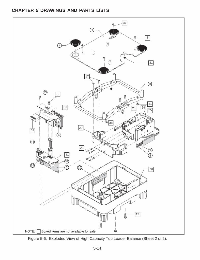
5-14
CHAPTER 5 DRAWINGS AND PARTS LISTS
Figure 5-6. Exploded View of High Capacity Top Loader Balance (Sheet 2 of 2).
3
31
18
312423
25
9
8
31
12
267
34
31
35
11
326
20
22
33 5
31
17
2
4
37
38
NOTE: Boxed items are not available for sale.

5-15
CHAPTER 5 DRAWINGS AND PARTS LISTS
5.2.7 High Capacity Top Loader Balance Parts List
TABLE 5-6. HIGH CAPACITY TOP LOADER BALANCE PARTS LIST (See Figure 5-6, Sheet 2)
KEY NO. PART NO. DESCRIPTION
2 11107001 Pan Mount, (High Capacity)
4 00239040 Cover, Housing, (High Capacity)
6 21201770 Main PCB, (High Capacity)
7 11107022 Power Supply PCB, (High Capacity)
8 21100246 Cable, Coil, 4 Position, (High Capacity)
9 21100248 Cable Cell, 8 Position, (High Capacity)
11 21202417 Cable, Main PCB to Power Supply PCB, (High Capacity)
18 00239108 Overload Protection, (High Capacity)
26 00239039 Cable Guide, (High Capacity)
33 00239035 Plate, Protective, (High Capacity)
34 00239038 Plate, Insulating, (High Capacity)
35 00239034 Plate Shielding, (High Capacity)
NOTES: 1. In all cases where a part is replaced, the balance shall be thoroughlychecked after the replacement is made. The balance must meet theparameters of all applicable specifications in this manual.
2. Ohaus replacement parts warranty only applies to parts purchasedfrom Ohaus Corporation.

5-16
CHAPTER 5 DRAWINGS AND PARTS LISTS
Figure 5-7. Exploded View of Monoblock Load Cell for High Capacity Top Loader Balance
3
25
4
NOTE: Boxed items are not available for sale.

5-17
CHAPTER 5 DRAWINGS AND PARTS LISTS
5.2.8 Monoblock High Capacity Top Loader Balance Parts List
TABLE 5-7. MONOBLOCK HIGH CAPACITY TOP LOADER PARTS LIST (See Figure 5-7)
KEY NO. PART NO. DESCRIPTION
2 21100003 Position Sensor PCB, (High Capacity)
4 00217400 Force Coil Lever Assembly Monoblock, Explorer, Voyager
5 21100229 Servomotor, (High Capacity)
NOTES: 1. In all cases where a part is replaced, the balance shall be thoroughlychecked after the replacement is made. The balance must meet theparameters of all applicable specifications in this manual.
2. Ohaus replacement parts warranty only applies to parts purchasedfrom Ohaus Corporation.

5-18
CHAPTER 5 DRAWINGS AND PARTS LISTS
Figure 5-8. Exploded View of Explorer Display.
1
2
3
>O/T<
>O/T<
4

5-19
CHAPTER 5 DRAWINGS AND PARTS LISTS
5.2.9 Explorer Display Parts List
TABLE 5-8. EXPLORER DISPLAY PARTS LIST (See Figure 5-8)
KEY NO. PART NO. DESCRIPTION
1 11108414 Switch, Membrane, Explorer
2 11136112 Cover, Display, Coated, Explorer, Voyager, Explorer Pro, High Capacity
3 11108413 Display PCB Assembly, Explorer
4 11108525 Display Module complete, Explorer
NOTES: 1. In all cases where a part is replaced, the balance shall be thoroughlychecked after the replacement is made. The balance must meet theparameters of all applicable specifications in this manual.
2. Ohaus replacement parts warranty only applies to parts purchasedfrom Ohaus Corporation.

5-20
CHAPTER 5 DRAWINGS AND PARTS LISTS
1
2
3
>O/T<
>O/T<
Figure 5-9. Exploded View of Explorer High Capacity Display.

5-21
CHAPTER 5 DRAWINGS AND PARTS LISTS
5.2.10 Explorer High Capacity Display Parts List
TABLE 5-9. EXPLORER HIGH CAPACITY DISPLAY PARTS LIST (See Figure 5-9)
KEY NO. PART NO. DESCRIPTION
1 11108481 Membrane Switch, Explorer, High Capacity
2 11136112 Cover, Display, Coated, Explorer, Voyager, High Capacity
3 450111-010 Display Assembly Complete, Explorer, High Capacity
NOTES: 1. In all cases where a part is replaced, the balance shall be thoroughlychecked after the replacement is made. The balance must meet theparameters of all applicable specifications in this manual.
2. Ohaus replacement parts warranty only applies to parts purchasedfrom Ohaus Corporation.

5-22
CHAPTER 5 DRAWINGS AND PARTS LISTS
Figure 5-10. Exploded View of Explorer Pro, Voyager Display.
>O/T<
>O/T<
3
10
1
11

5-23
CHAPTER 5 DRAWINGS AND PARTS LISTS
5.2.11 Explorer Pro, Voyager Display Parts List
TABLE 5-10. EXPLORER PRO, VOYAGER DISPLAY PARTS LIST (See Figure 5-10)
KEY NO. PART NO. DESCRIPTION
1 11136410 Switch, Membrane, Voyager
1 11136409 Switch, Membrane, Explorer Pro,
3 11136406 LCD Display PCB (Top), Explorer Pro, Voyager
10 11108417 Bulb, Replacement, Explorer Pro, Voyager
--- 80850042 In use cover, Explorer, Explorer Pro, Voyager (Not shown)
11 11108407 LCD Display PCB (Bottom), Explorer pro, Voyager, Voyager Pro, no PSD orsoftware
11 11136713 LCD Display PCB (Bottom), Explorer Pro w/PSD
11 11136714 LCD Display PCB (Bottom), Voyager Pro w/PSD
NOTES: 1. In all cases where a part is replaced, the balance shall be thoroughlychecked after the replacement is made. The balance must meet theparameters of all applicable specifications in this manual.
2. Ohaus replacement parts warranty only applies to parts purchasedfrom Ohaus Corporation.

5-24
CHAPTER 5 DRAWINGS AND PARTS LISTS
Figure 5-11. Exploded View of Voyager, Explorer Pro High Capacity Display.
>O/T<
>O/T<
3
10
1
11

5-25
CHAPTER 5 DRAWINGS AND PARTS LISTS
5.2.12 Voyager, Explorer Pro, High Capacity, Display Parts List
TABLE 5-11. VOYAGER, EXPLORER PRO, HIGH CAPACITY DISPLAY PARTS LIST (See Figure 5-11)
KEY NO. PART NO. DESCRIPTION
1 11136480 Membrane Switch, Explorer Pro, High Capacity
1 11108480 Membrane Switch, Voyager, High Capacity
3 11136406 LCD Display PCB (Top), Explorer Pro, Voyager, High Capacity
10 11108417 Bulb, Replacement, Explorer Pro, Voyager and High capacity
11 11108483 LCD Display PCB (Bottom), Voyager, High Capacity, no PSD orsoftware
11 11136716 LCD Display PCB (Bottom), Explorer Pro, High Capacity w/PSD
NOTES: 1. In all cases where a part is replaced, the balance shall be thoroughlychecked after the replacement is made. The balance must meet theparameters of all applicable specifications in this manual.
2. Ohaus replacement parts warranty only applies to parts purchasedfrom Ohaus Corporation.

5-26
CHAPTER 5 DRAWINGS AND PARTS LISTS

APPENDIX A - EXPLORER EP LOADER
A-1
A.1 Requirements for EP Loader• Pentium 90MHz or higher microprocessor
• VGA 640x480 or higher resolution screen
• Microsoft Windows NT 4.0 or later, or Microsoft Windows 95 or later
• Minimum 24 MB RAM for Windows 95/98, 32 MB for Windows NT
• Minimum 10 MB free space
• CD-ROM
• RS232 cable, Ohaus part number AS017-09 (9 pin) or AS017-02 (25 pin)
• HyperTerminal or another communications program to verify the data.
• If the balance is a Voyager an Explorer display module will be needed.
A.2 Limitations• The EP Loader software can not be used to restore the personality data in an Explorer
that has the internal calibration option.
A.3 Installing EP Loader Software1. Insert the EP Loader CD into the CD-ROM.
2. Run the setup executable found on the EP Loader CD to start the installation wizard.
3. Follow the instructions in the installation wizard.
4. If the CD is not available the software can be downloaded at the followingURL. HTTP:// fileshare.ohaus.com/docushare/.
a. Click on Login.
b. Login = ServiceAPassword = aserviceBoth are case sensitive
c. Click on the Xerox logo at the upper left.
d. Click on Technical Support.
e. Click on Service Notes.
f. Click on Authorized Service Centers.
g. Click on Explorer Pro Tools.
h. Download all 5 files.

APPENDIX A - EXPLORER EP LOADER
A-2
A.4 Run EP Loader Software1. Click on EP Loader icon located in Start>Programs>EP Loader
2. The following screen will be displayed:

APPENDIX A - EXPLORER EP LOADER
A-3
A.5 Setup the Balance in Manufacturing Mode1. Remove power from the balance
2. Remove the pan.a. It may be necessary to remove two screws holding the display assembly in place
under the balance.
3. Unclip the display module and ease it forward until the module is clear of the edge of thedraft shield or the edge of the top balance cover on 0.01g and 0.1g resolution balances.a. If the balance is a Voyager install an Explorer display module.b. Ensure that the display PCB cannot short to the balance casing.
4. Remove the 2 screws securing the draft shield or top balance cover in place.
5. Remove the plastic pan support clips, if fitted.
6. Remove the draft shield or top balance cover.
7. Install the manufacturing link in the position shown in Figure A-1.a. Install the link by pushing down on the top and then rotating it 90° to lock it in
position.b. If a manufacturing link is not available remove the RF shield and locate the hole
through the printed circuit board that was under the manufacturing link access hole.Short the two pads just to the front of this hole.
8. Apply power to the balance
9. The balance will come on by itself and display MFG before the normal turn on cycle.
A.6 Connect the Balance to a PC1. Connect the RS232 interface cable between the balance and the PC.
a. Note that for a 9-pin to 9-pin cable; ensure the connector marked BAL is connectedto the balance.
2. Check communication between the balance and the PC.a. In the EP Loader, single-click on the Comm Setup button. The following pop-up
screen will be displayed:
b. Modify the communication parameters of the EP Loader to match the balance, thensingle click the Comm Test button. A pop-up screen will be displayed to indicate thatthe communication has failed or passed.

APPENDIX A - EXPLORER EP LOADER
A-4
A.7 Personality Data Label Entry1. Locate the Personality Data Label on the balance. Refer to Figure A-1.
a. The data will be located on the RF shield.
CAUTION
This software cannot be used to download personality data for models having
internal calibration (AutoCal). Only the TC data can be downloaded.
2. In the same order as listed on the label, input the Personality Data Label information intothe Personality Data grid of the EP Loader. After entering the data in Figure A-2 the loaderwilllook like the picture below. See next page for display.
610 x 1 mg 00000768C1A2 04.08.200383C1 03E4 F92F 1C52 2990 070C 42CF 17E7 CF8F 8E5F AB2FE3AD B70F 0F3B 74D3 4FB4 01B0 9A06 B92F 1C46 6957 0F38475A 4C5F CB83 8C1A F8DB 1DA6 2957 1F50 408A 486D B1E7DD32 F92F 1C52 2957 0F38 408A 4EB6 81E1
Figure A-1. RF Shield
Figure A-2. Personality Data

APPENDIX A - EXPLORER EP LOADER
A-5
A.7 Personality Data Label Entry (Cont.)
3. Confirm that the Balance Personality Data from the label matches the data that wasinputted into the Personality Data section of the EP Loader. If not edit the data. If onlythe personality data is to be loaded uncheck the TC Data box in the Data Type box seebelow.

APPENDIX A - EXPLORER EP LOADER
A-6
A.8 Temperature Compensation (TC) Data Entry1. Locate the TC Data Label on the balance. For the location see Figure A-1.
a. There are 2 major styles of label currently in use, please refer to Figure A-3.
2. Identify the values labeled in the diagram as “A” to “J”, If the balance does not haveinternal calibration there will only be values “A” to :G”. Then input into the TC Datalocation of the EP Loader accordingly. The Loader will look like the picture below.
Figure A-3. TC Data

APPENDIX A - EXPLORER EP LOADER
A-7
A.8 Temperature Compensation (TC) Data Entry (Cont.)
2.(Cont.)a. When the first entry of the AutoCal TC data “H” is entered the main screen will
change. See below. The added grid is for loading the AutoCal Data in Explorer Probalances. It is not used for Explorer balances.
3. Confirm that the TC Data from the label was correctly inputted into the TC Data of the EPLoader
m/

APPENDIX A - EXPLORER EP LOADER
A-8
A.9 Downloading Personality Data and/or TC Data into the Balance1. In the Data Type box of the EP Loader , there are two check fields to allow selections of
Personality Data and/or TC Data to be downloaded into the balance. If both types of dataneed to be downloaded it can be done at one time.
2. To initiate download process, single-click the Download button on the EP Loader.
3. In the lower right-hand corner of the EP Loader, a status bar will appear to display theprogress of the download.
4. After the data is downloaded an error message may be displayed. Turn the balance off,unplug it, plug it back in and perform the MFG and if necessary the MFG WT calibrations.
5. If the error persists, recheck the personality data and edit it as necessary.
A.10 Saving Personality Data and TC Data1. The Personality Data and TC Data should be saved at this time as a complete file, press
Ctrl+S on the keyboard or select File>Save in the menu of the EP Loader.
2. For a new Data file created, a ‘Save As’ pop-up screen will appear to allow the Data fileto be saved under the desired filename.
3. To save an existing Data file under a different filename, press Ctrl+A on the keyboard orselect File>’Save As’ in the menu of the EP Loader.
A.11 Opening Data Files1. To open an existing Data file, press Ctrl+O on the keyboard or select File>Open in the
menu of the EP Loader.
2. To open a recently used Data file, select the desired file under the File menu of the EPLoader.
A.12 Clear EP Loader1. To clear data displayed in the EP Loader, single–click the Clear button.
A.13 Confirm TC Data Download1. Open and configure HyperTerminal to match the balance communication parameters.
2. With the balance still in manufacturing mode send the command XDTC to the balance.
3. The balance will respond with the TC data, this response should agree with the TC dataloaded.

APPENDIX B - EXPLORER PRO EP LOADER
B-1
B.1 Requirements for EP Loader• Pentium 90MHz or higher microprocessor
• VGA 640x480 or higher resolution screen
• Microsoft Windows NT 4.0 or later, or Microsoft Windows 95 or later
• Minimum 24 MB RAM for Windows 95/98, 32 MB for Windows NT
• Minimum 10 MB free space
• CD-ROM
• RS232 cable, Ohaus part number AS017-09 (9 pin) or AS017-02 (25 pin)
• HyperTerminal or another communications program to verify the data.
• Explorer display
B.2 Installing EP Loader Software1. Insert the EP Loader CD into the CD-ROM.
2. Run the setup executable found on the EP Loader CD to start the installation wizard.
3. Follow the instructions in the installation wizard.
4. If the CD is not available the software can be downloaded at the followingURL. HTTP://fileshare.ohaus.com/docushare/.
a. Click on Login.
b. Login = ServiceAPassword = aserviceBoth are case sensitive
c. Click on the Xerox logo at the upper left.
d. Click on Technical Support.
e. Click on Service Notes.
f. Click on Authorized Service Centers.
g. Click on Explorer Pro Tools.
h. Download all 5 files.

APPENDIX B - EXPLORER PRO EP LOADER
B-2
B.3 Run EP Loader Software1. Click on EP Loader icon located in Start>Programs>EP Loader
2. The following screen will be displayed:

APPENDIX B - EXPLORER PRO EP LOADER
B-3
B.4 Setup the Balance in Manufacturing Mode1. Remove power from the balance.
2. Remove the pan.a. It may be necessary to remove two screws holding the display assembly in place
under the balance.
3. Unclip the display module and ease it forward until the module is clear of the edge of thedraft shield or the edge of the top balance cover on 0.01g and 0.1g resolution balances.a. Remove the Explorer Pro display module and install an Explorer display.
b. Ensure that the display PCB cannot short to the balance casing.
4. Remove the 2 screws securing the draft shield or top balance cover in place.
5. Remove the plastic pan support clips, if fitted.
6. Remove the draft shield or top balance cover.
7. Install the manufacturing link in the position shown in Figure B-1.
a. Install the link by pushing down on the top and then rotating it 90° to lock it inposition.
b. If a manufacturing link is not available remove the RF shield and locate the holethrough the printed circuit board that was under the manufacturing link access hole.Short the two pads just to the front of this hole.
8. Apply power to the balance.
9. The balance will come on by itself and display MFG before the normal turn on cycle.
Figure B-1. RF Shield.

APPENDIX B - EXPLORER PRO EP LOADER
B-4
B.5 Connect the Balance to a PC1. Connect the RS232 interface cable between the balance and the PC.
a. Note that for a 9-pin to 9-pin cable; ensure the connector marked BAL is connectedto the balance.
2. Check communication between the balance and the PC.a. In the EP Loader, single-click on the Comm Setup button. The following pop-up
screen will be displayed:
b. Modify the communication parameters of the EP Loader to match the balance, thensingle click the Comm Test button. A pop-up screen will be displayed to indicate thatthe communication has failed or passed.
B.6 Temperature Compensation (TC) Data Entry1. Locate the TC Data Label on the balance. It will be under the display module. Refer to
Figure B-2.
Figure B-2. TC Data.
2. Identify the values labeled in the diagram as “A” to “J”, if the balance does not haveinternal calibration only “A” to “G” will be on the label. Then input into the TC Datalocation of the EP Loader accordingly. The Loader will look like the picture on the nextpage.

APPENDIX B - EXPLORER PRO EP LOADER
B-5
B.6 Temperature Compensation (TC) Data Entry (Cont.)
a. When the first entry of the AutoCal TC data “H” is entered the main screen willchange. See next page. The added grid is for loading the AutoCal data.
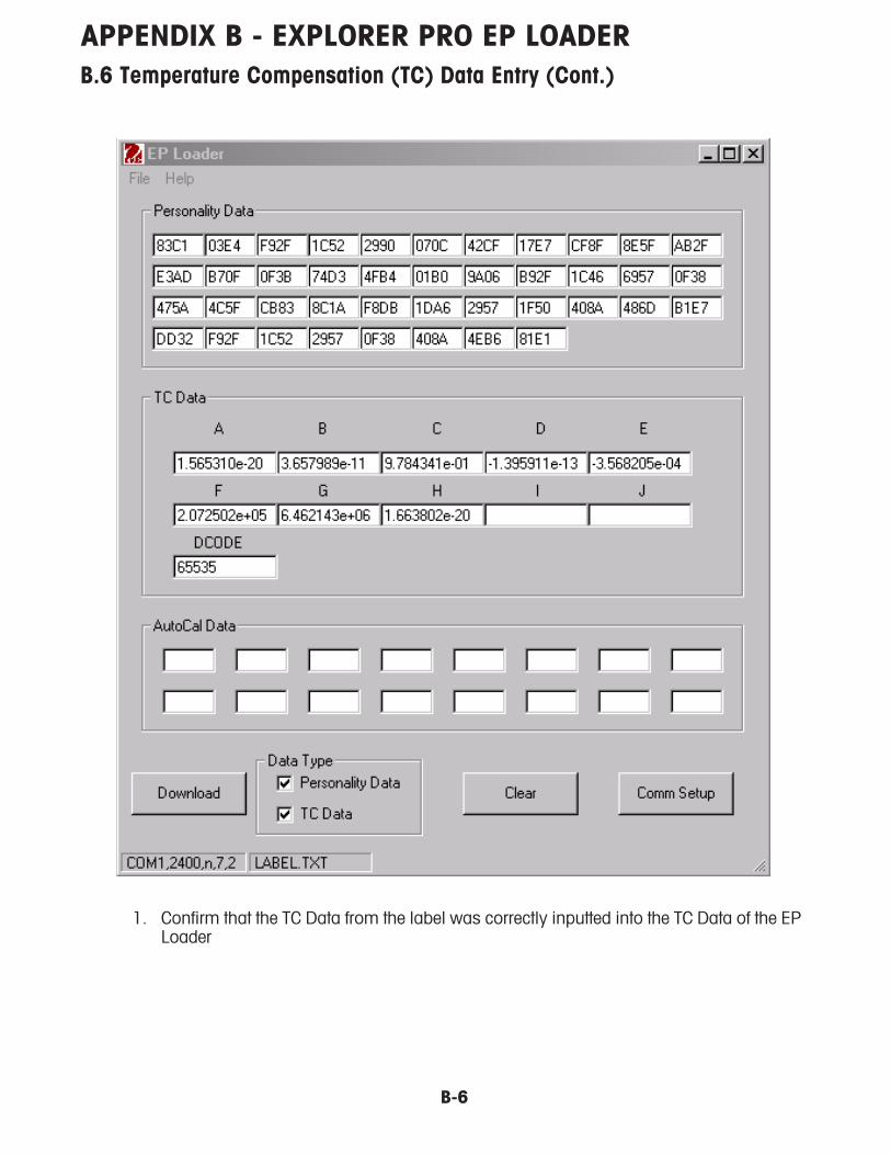
APPENDIX B - EXPLORER PRO EP LOADER
B-6
B.6 Temperature Compensation (TC) Data Entry (Cont.)
1. Confirm that the TC Data from the label was correctly inputted into the TC Data of the EPLoader
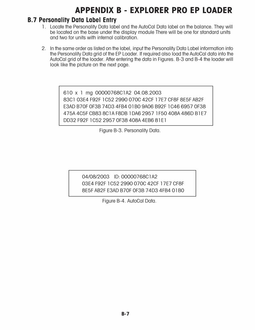
APPENDIX B - EXPLORER PRO EP LOADER
B-7
B.7 Personality Data Label Entry1. Locate the Personality Data label and the AutoCal Data label on the balance. They will
be located on the base under the display module There will be one for standard unitsand two for units with internal calibration.
2. In the same order as listed on the label, input the Personality Data Label information intothe Personality Data grid of the EP Loader. If required also load the AutoCal data into theAutoCal grid of the loader. After entering the data in Figures. B-3 and B-4 the loader willlook like the picture on the next page.
Figure B-3. Personality Data.
610 x 1 mg 00000768C1A2 04.08.2003
83C1 03E4 F92F 1C52 2990 070C 42CF 17E7 CF8F 8E5F AB2F
E3AD B70F 0F3B 74D3 4FB4 01B0 9A06 B92F 1C46 6957 0F38
475A 4C5F CB83 8C1A F8DB 1DA6 2957 1F50 408A 486D B1E7
DD32 F92F 1C52 2957 0F38 408A 4EB6 81E1
04/08/2003 ID: 00000768C1A2
03E4 F92F 1C52 2990 070C 42CF 17E7 CF8F
8E5F AB2F E3AD B70F 0F3B 74D3 4FB4 01B0
Figure B-4. AutoCal Data.
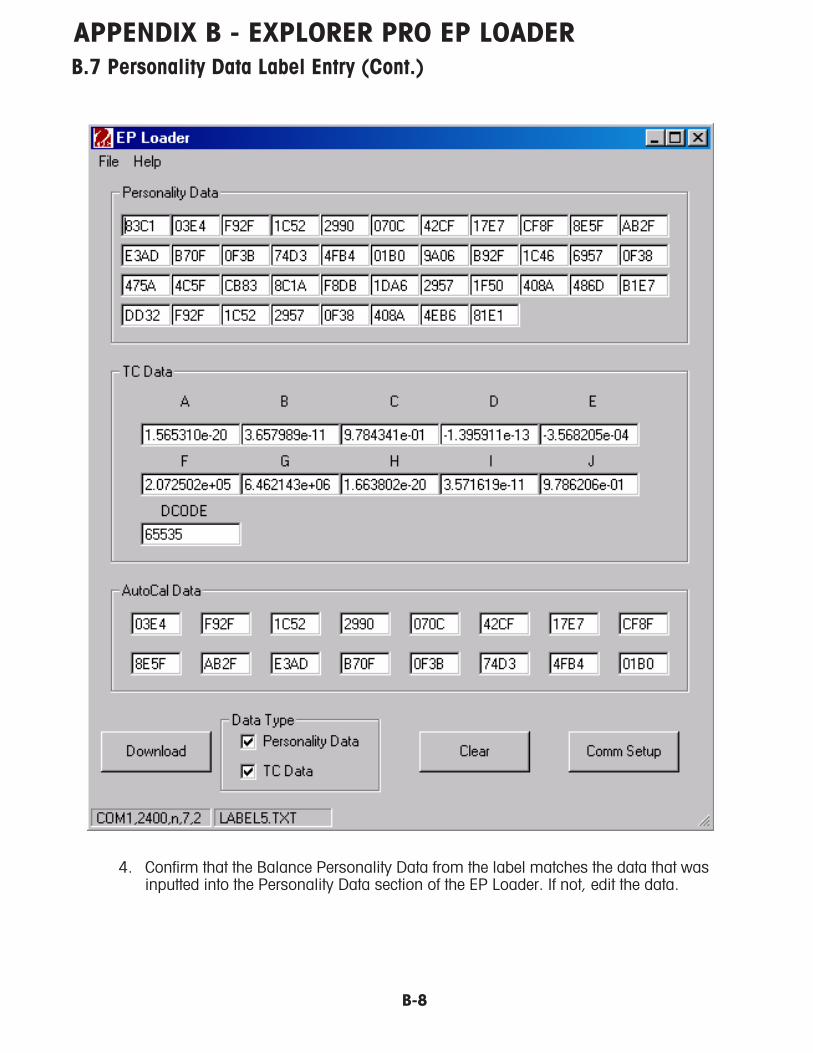
APPENDIX B - EXPLORER PRO EP LOADER
B-8
B.7 Personality Data Label Entry (Cont.)
4. Confirm that the Balance Personality Data from the label matches the data that wasinputted into the Personality Data section of the EP Loader. If not, edit the data.

APPENDIX B - EXPLORER PRO EP LOADER
B-9
B.8 Downloading Personality Data and/or TC Data Into the Balance1. In the Data Type box of the EP Loader , there are two check fields to allow selections of
Personality Data and/or TC Data to be downloaded into the balance. If both types of dataneed to be downloaded it can be done at one time.
2. To initiate download process, single-click the Download button on the EP Loader.
3.1 In the lower right-hand corner of the EP Loader, a status bar will appear to display theprogress of the download.
4. After the data is downloaded an error message may be displayed. Turn the balance off,unplug it, plug it back in and perform the MFG and if necessary the MFG WT calibrations.
5. If the error persists, recheck the personality data and edit it as necessary.
B.9 Saving Personality Data and TC Data1. The Personality Data and TC Data should be saved at this time as a complete file, press
Ctrl+S on the keyboard or select File>Save in the menu of the EP Loader.
2. For a new Data file created, a ‘Save As’ pop-up screen will appear to allow the Data fileto be saved under the desired filename.
3. To save an existing Data file under a different filename, press Ctrl+A on the keyboard orselect File>’Save As’ in the menu of the EP Loader.
B.10 Opening Data files1. To open an existing Data file, press Ctrl+O on the keyboard or select File>Open in the
menu of the EP Loader.
2. To open a recently used Data file, select the desired file under the File menu of the EPLoader.
B.11 Clear EP Loader1. To clear data displayed in the EP Loader, single–click the Clear button.
B.12 Confirm TC Data Download1. Open and conFig. HyperTerminal
2. With the balance still in manufacturing mode send the command XDTCXDTCXDTCXDTCXDTC to the balance.
3. The balance will respond with the TC data, this response should agree with the TC dataloaded.

APPENDIX B - EXPLORER PRO EP LOADER
B-10
APPENDIX C - PRODUCTION MODE CALIBRATION
C-1
C.1 Preparation1. Remove power from the balance.
2. Remove the pan. It may be necessary to remove two screws holding the display assemblyin place under the balance.
3. Unclip the display module and ease it forward until the module is clear of the edge of thedraft shield or the edge of the top balance cover on 0.01g and 0.1g resolution balances.If the balance is a Voyager or Explorer Pro install an Explorer display module.Ensure that the display PCB cannot short to the balance casing.
4. Remove the 2 screws securing the draft shield or top balance cover in place.
5. Remove the plastic pan support clips, if required.
6. Remove the draft shield or top balance cover.
7. Install the manufacturing link in the position shown in (refer to fig in eploader Instructions).Install the link by pushing down on the top and then rotating it 90° to lock it in position.If a manufacturing link is not available remove the RF shield and locate the hole throughthe printed circuit board that was under the manufacturing link access hole. Short thetwo pads just to the front of this hole.
8. Insure that the pan, pan support and any hardware that makes up the dead load is onthe balance. The turn on zero will be written to memory during the calibration.
9. Apply power to the balance. The balance will come on by itself and display MFG beforethe normal turn on cycle. This indicates the balance is in manufacturing mode.
C.2 Manufacturing Calibration (MFg) Procedure1. Press and release Setup. The balance will display MFGTEST.
2. Press and release the right arrow once. The balance will display CAL.
3. Press and release Enter/Print. The balance will display CAL TYPE.
4. Press and release Enter/Print. The balance will display MFg.
5. Press and release Enter/Print. The balance will display WORKING and a changing number.
6. The balance will then display PUT WT and a mass value. Place masses totaling thatvalue on the pan.
7. Press and release the Enter/Print. The balance will display WORKING and a changingnumber.
8. The balance will then display PUT WT and another mass value. Place masses totalingthat value on the pan.
9. Press and release the Enter/Print. The balance will display WORKING and a changingnumber.
10. The balance will display CAL SET and return to the Weigh mode.

APPENDIX C - PRODUCTION MODE CALIBRATION
C-2
C.3 Manufacturing Weight Calibration (MFgWt) ProcedureThis calibration is required if the balance has internal calibration. This procedure restores the
internal weight calibration factor that is erased by the MFg calibration.
1. Press and release Setup. The balance will display MFGTEST.
2. Press and release the right arrow once. The balance will display CAL.
3. Press and release Enter/Print. The balance will display CAL TYPE.
4. Press and release Enter/Print. The balance will display MFg.
5. Press and release the up arrow. The balance will display MFgWt.
6. Press and release Enter/Print. The balance will display INCAL. The balance may alsodisplay Clr Pan briefly. If this happens clear the pan or just press and release Enter/Printif the pan is clear.
7. You will hear the calibration drive motor turning. The balance may go through a fewrepeat cycles. This is normal if the environment is unstable. You may see UNSTBLE.,this is also an indication that the environment is unstable. Under these conditions thebalance may not calibrate.
8. The balance will then display PUT WT and a mass value. Place masses totaling therequested value on the pan.
9. Press and release Enter/Print. The balance will display WORKING and a changing number.
10. The balance will then return to the weigh mode.

APPENDIX D - REPLACING BOTTOM DISPLAY BOARD
D-1
This procedure is used when replacing the bottom display board on the Voager, explorer Pro and Voyager
pro balances.
D.1 Replacing the Bottom Display Board on Voyager, Explorer Pro andVoyager Pro Balances
The bottom board of the display can be replaced using the following steps.1. Unplug the Balance
2. Remove the complete display from the balance.
3. Disconnect the membrane switch ribbon cable from the bottom board.
4. Remove the 4 screws that hold the circuit board assembly into the housing and lift the assemblyfrom the housing.
5. Disconnect the wire connector for the display back lighting from the bottom board
6. Remove the 4 screws that hold the two circuit boards together.
7. Gently separate the two boards.
8. Remove the microprocessor chip from the old board using a PLCC extractor. Note the softwareversion on the chip.
9. Install the chip into the new bottom board.
10. If necessary gently break away the excess pieces of the circuit board so that the board is thesame shape and size as the old board and looks like the photo below.
11. Short the two pins shown below.
12. Remove the paper tab from between the battery and the positive terminal.
13. Reassemble the complete display assembly.
14. Reinstall the display assembly on the balance.
15. Reconnect the power to the balance.
16. Follow the Flash instructions below.
D.2 Explorer Pro, Voyager and Voyager Pro Display Flash InstructionsThis software tool is used to load the flash bank files into the bottom board of the display afterreplacement of the bottom board. After reassembling the balance follow these steps to load the flashbank files.
1. Using an internet browser access the Docushare website at www.fileshare.ohaus.com/docushare/
2. Download the following files from the Explorer & Voyager Display Flash folder, Setup.exe andthe bank files matching the version of software marked on the microprocessor noted above.

APPENDIX D - REPLACING BOTTOM DISPLAY BOARD
D-2
D.2 Explorer Pro, Voyager and Voyager Pro Display Flash Instructions(Cont.)
3. Install the flash loader program by running the Setup.exe file and following the prompts of theinstall shield wizard.
4. Unzip the required bank files into their own individual folder. This folder will contain bank fileswith the extension .H00, .H01 … H0X . There will also be at least 1 text file named nlogo.txt.Additional files may be present but are not essential
5. Connect your computer to the balance
6. Turn the balance on. The display will read Verify flash bank checksum followed by individuallines for each bank and the status failed.
7. Use a program such as Hyper Terminal to test the communications from your computer to thebalance. The settings while the service pins are shorted are 9600 baud, Parity None, Data Bits8, Stop Bits 1, Handshake None. Send the balance a V command to test communications. Thebalance will respond with the software version.
8. Start the Flash Programmer from your programs menu. Note the communication settings and ifnecessary change to match the communications port you are using. You should not haveYou should not haveYou should not haveYou should not haveYou should not haveto change the other parameters.to change the other parameters.to change the other parameters.to change the other parameters.to change the other parameters.
9. The communications port settings are displayed at the top of the screen and can be changed byclicking the “comm. setup” button and selecting the appropriate settings from the pick list.PLEASE NOTE: THE “TEST COMM! “ Button does not function in this software. If you need to testthe communications use Hyper terminal or another program.

APPENDIX D - REPLACING BOTTOM DISPLAY BOARD
D-3
D.2 Explorer Pro, Voyager and Voyager Pro Display Flash Instructions(Cont.)
10. Select the balance you are downloading to then click on browse and select the location of thebank files to be installed.
11. Click on the download button to start the download process. A progress bar will be shown onyour computer and a message on the balance display showing the progress of the download.
12. When complete. Remove and reapply power to the balance. The balance will then display VerifyFlash Bank Checksum… across the top of the display. The following lines will show each bankfollowed by –OK! . At the bottom of the display it will show KEY= This allows you to test thekeys individually. The display will be as shown in the table below.
Explorer Models On/Off Menu Print Mode O/T Up ArrowDown Arrow Right Arrow Left Arrow Enter
Voyager Models On/Off Go back Help Print O/T Up ArrowDown Arrow Right Arrow Left Arrow Enter
Display Key = ON/OFF GO BACK HELP PRINT TARE UP DOWN RIGHT LEFT ENTER
13. The procedure is complete. Remove power from the balance and remove the short across the twopins.
SHORTTHESE PINS

APPENDIX D - REPLACING BOTTOM DISPLAY BOARD
D-4


PN 80250985 SERVICE MANUAL - EXPLORER, EXPLORER PRO AND VOYAGER BALANCES
*80250985*
Test Equipment Depot - 800.517.8431 - 99 Washington Street Melrose, MA 02176 - TestEquipmentDepot.com