Embed Size (px)
Citation preview
Fuller® Heavy Duty Transmissions
Service ManualsFuller Heavy Duty Transmissions
TRSM0415
October 2007
More time on the road ®
Before starting a vehicle always beseated in the drivers seat, place thetransmission in neutral, set the park-ing brakes and disengage the clutch.
Before working on a vehicle place thetransmission in neutral, set the park-ing brakes and block the wheels.
Before towing the vehicle place thetransmission in neutral, and lift therear wheels off the ground or discon-nect the driveline to avoid damage tothe transmission during towing.
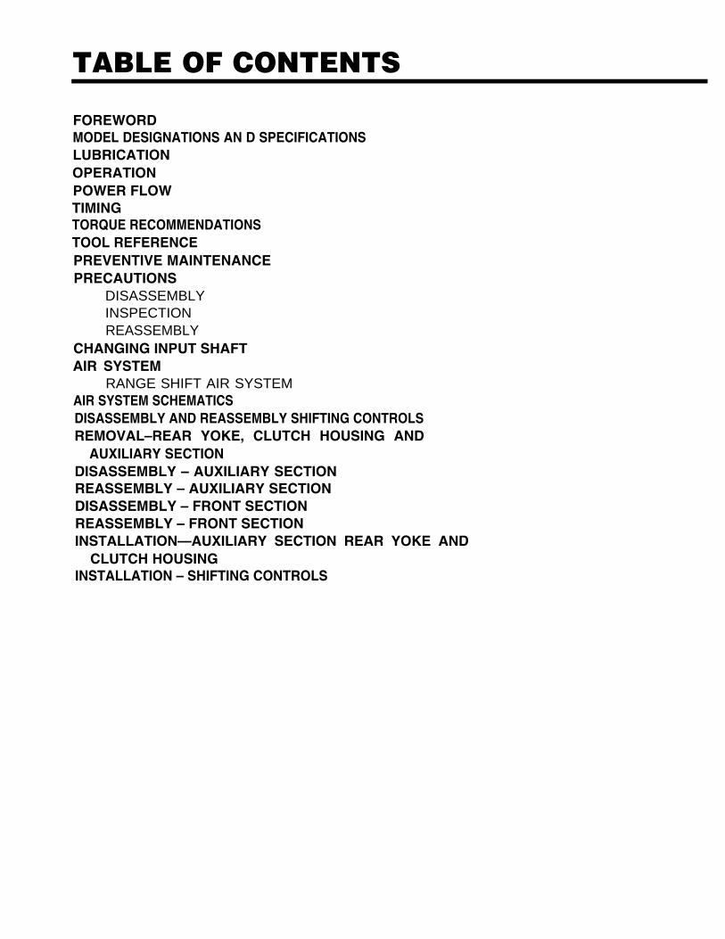
TABLE OF CONTENTS
FOREWORDMODEL DESIGNATIONS AN D SPECIFICATIONS LUBRICATIONOPERATIONPOWER FLOW TIMINGTORQUE RECOMMENDATIONS TOOL REFERENCEPREVENTIVE MAINTENANCEPRECAUTIONS
DISASSEMBLYINSPECTIONREASSEMBLY
CHANGING INPUT SHAFTAIR SYSTEM
RANGE SHIFT AIR SYSTEMAIR SYSTEM SCHEMATICS DISASSEMBLY AND REASSEMBLY SHIFTING CONTROLSREMOVAL–REAR YOKE, CLUTCH HOUSING AND
AUXILIARY SECTION DISASSEMBLY – AUXILIARY SECTIONREASSEMBLY – AUXILIARY SECTIONDISASSEMBLY – FRONT SECTIONREASSEMBLY – FRONT SECTIONINSTALLATION—AUXILIARY SECTION REAR YOKE AND
CLUTCH HOUSING INSTALLATION – SHIFTING CONTROLS
FOREWORDThis manual is designed to provide detailed infor-mation necessary to service and repair the Fuller®
Transmission listed on the cover.As outlined in the Table of Contents, the manual
is divided into 3 main sections:a. Technical information and referenceb. Removal, disassembly, reassembly and
installationc. Options
The format of the manual is designed to be fol-lowed in its entirety if complete disassembly andreassembly of the transmission is necessary. But ifonly one component of the transmission needs tobe repaired, refer to the Table of Contents for thepage numbers showing that component. For exam-ple, if you need to work on the Shifting Controls,you will find instructions for removal, disassemblyand reassembly on page 26. Instructions for instal-lation are on page 88. Service Manuals, IllustratedParts Lists, Drivers Instructions, and other forms of
product service information for these and otherFuller Transmissions are available upon request. ATechnical Literature Order Form may be found in theback of this manual*. You may also obtain ServiceBulletins, detailing information on product improve-ments, repair procedures and other service-relatedsubjects by writing to the following address:
EATON CORPORATIONTRANSMISSION DIVISIONTechnical Service DepartmentP.O. Box 4013Kalamazoo, Michigan 49003(61 6) 342-3344
Every effort has been made to ensure the accuracy of all information in this brochure. However, Eaton Transmission Division makes noexpressed or implied warranty or representation based on the enclosed information. Any errors or omissions may be reported to Train-ing and Publications, Eaton Transmission Division, P.O. Box 4013, Kalamazoo, Ml 49003.
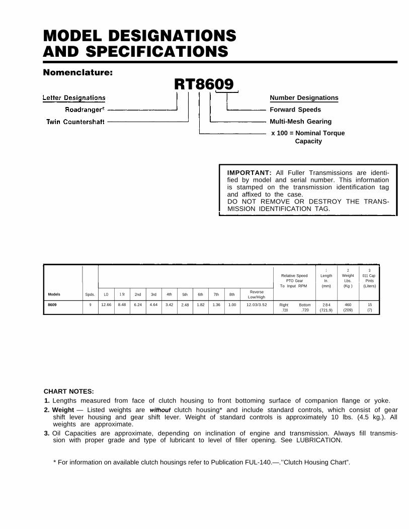
MODEL DESIGNATIONSAND SPECIFICATIONSNomenclature:
RT8609Number Designations
Forward Speeds
Multi-Mesh Gearing
x 100 = Nominal TorqueCapacity
IMPORTANT: All Fuller Transmissions are identi-fied by model and serial number. This informationis stamped on the transmission identification tagand affixed to the case.DO NOT REMOVE OR DESTROY THE TRANS-MISSION IDENTIFICATION TAG.
1 2 3Relative Speed Length Weight 011 Cap
PTO Gear In. Lbs. PintsTo Input RPM (mm) (Kg ) (Liters)
Models Spds. LO 1 St 2nd 3rd 4th 5th 6th 7th 8thReverse
Low/High
8609 9 12.66 8.48 6.24 4.64 3.42 2.48 1.82 1.36 1.00 12.03/3.52 Right Bottom 2 8 4 460 15.720 .720 (721.9) (209) (7)
CHART NOTES:1. Lengths measured from face of clutch housing to front bottoming surface of companion flange or yoke.2. Weight — Listed weights are without clutch housing* and include standard controls, which consist of gear
shift lever housing and gear shift Iever. Weight of standard controls is approximately 10 lbs. (4.5 kg.). Allweights are approximate.
3. Oil Capacities are approximate, depending on inclination of engine and transmission. Always fill transmis-sion with proper grade and type of lubricant to level of filler opening. See LUBRICATION.
* For information on available clutch housings refer to Publication FUL-140.—.’’Clutch Housing Chart”.
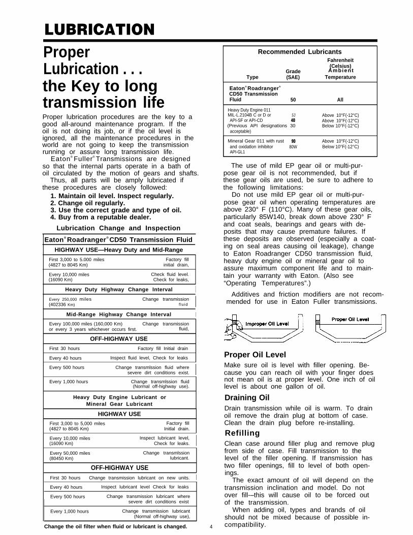
LUBRICATIONProperLubrication . . . Ambient
the Key to longtransmission lifeProper lubrication procedures are the key to agood all-around maintenance program. If theoil is not doing its job, or if the oil level isignored, all the maintenance procedures in theworld are not going to keep the transmissionrunning or assure long transmission life.
Eaton® Fuller® Transmissions are designedso that the internal parts operate in a bath ofoil circulated by the motion of gears and shafts.
Thus, all parts will be amply lubricated ifthese procedures are closely followed:
1. Maintain oil level. Inspect regularly.2. Change oil regularly.3. Use the correct grade and type of oil.4. Buy from a reputable dealer.
Lubrication Change and Inspection
Eaton® Roadranger® CD50 Transmission FluidHIGHWAY USE—Heavy Duty and Mid-Range
First 3,000 to 5.000 miles Factory fill(4827 to 8045 Km) initial drain,
Every 10,000 miles Check fluid level.(16090 Km) Check for leaks,
Heavy Duty Highway Change Interval IEvery 250,000 miles Change transmission(402336 Km) f lu id I
Mid-Range Highway Change Interval IEvery 100,000 miles (160,000 Km) Change transmissionor every 3 years whichever occurs first. fluid,
OFF-HIGHWAY USE
First 30 hours Factory fill Initial drain
Every 40 hours Inspect fluid level, Check for leaks
Every 500 hours Change transmlssion fluid wheresevere dirt conditions exist. I
Every 1,000 hours Change transmlssion fluid(Normal off-highway use).
Heavy Duty Engine Lubricant orMineral Gear Lubricant
HIGHWAY USE
First 3,000 to 5,000 miles Factory fill(4827 to 8045 Km) Initlal drain.
Every 10,000 miles Inspect lubricant level,(16090 Km) Check for leaks. IEvery 50,000 miles Change transmlssion(80450 Km) Iubricant.
OFF-HIGHWAY USEFirst 30 hours Change transmission lubricant on new units. IEvery 40 hours Inspect lubricant level Check for leaks
Every 500 hours Change transmission lubricant wheresevere dirt conditions exist
Every 1,000 hours Change transmission Iubricant(Normal off-highway use),
Change the oil filter when fluid or lubricant is changed.
Recommended LubricantsFahrenheit(Celsius)
GradeType (SAE) Temperature
Eaton® Roadranger®
CD50 TransmissionFluid 50 All
Heavy Duty Engine 011MIL-L.2104B C or D or 50 Above 10°F(-12°C)API-SF or API-CD 40 Above 10°F(-12°C)
(Previous API designations 30 Below 10°F(-12°C)acceptable)
Mineral Gear 011 with rust 90 Above 10°F(-12°C)and oxidatlon inhibitor 80W Below 10°F(-12°C)API-GL1
The use of mild EP gear oil or multi-pur-pose gear oil is not recommended, but ifthese gear oils are used, be sure to adhere tothe following limitations:
Do not use mild EP gear oil or multi-pur-pose gear oil when operating temperatures areabove 230° F (110°C). Many of these gear oils,particularly 85W140, break down above 230° Fand coat seals, bearings and gears with de-posits that may cause premature failures. Ifthese deposits are observed (especially a coat-ing on seal areas causing oil leakage), changeto Eaton Roadranger CD50 transmission fluid,heavy duty engine oil or mineral gear oil toassure maximum component life and to main-tain your warranty with Eaton. (Also see“Operating Temperatures”.)
Additives and friction modifiers are not recom-mended for use in Eaton Fuller transmissions.
Proper Oil LevelMake sure oil is level with filler opening. Be-cause you can reach oil with your finger doesnot mean oil is at proper level. One inch of oillevel is about one gallon of oil.
Draining OilDrain transmission while oil is warm. To drainoil remove the drain plug at bottom of case.Clean the drain plug before re-installing.
RefillingClean case around filler plug and remove plugfrom side of case. Fill transmission to thelevel of the filler opening. If transmission hastwo filler openings, fill to level of both open-ings.
The exact amount of oil will depend on thetransmission inclination and model. Do notover fill-–this will cause oil to be forced outof the transmission.
When adding oil, types and brands of oilshould not be mixed because of possible in-
4 compatibility.
LUBRICATIONOperating Temperatures—With Eaton® Roadranger ®
CD50 Transmission FluidHeavy Duty Engine Oiland Mineral Oil
The transmission should not be operated con-sistently at temperatures above 250°F (120°C).However, intermittent operating temperaturesto 300°F (149°C) will not harm the transmis-sion. Operating temperatures above 250°Fincrease the lubricant’s rate of oxidation andshorten its effective life. When the averageoperating temperature is above 250” F, thetransmission may require more frequent oilchanges or external cooling.
The following conditions in any combina-tion can cause operating temperatures of over250°F: (1) operating consistently at slowspeeds, (2) high ambient temperatures, (3) re-stricted air flow around transmission, (4) ex-haust system too close to transmission, (5)high horsepower, overdrive operation.
External oil coolers are available to reduceoperating temperatures when the above condi-tions are encountered.
Transmission Oil Coolers are:
Recommended— With engines of 350 H.P. and above
with overdrive transmissions
Required
— With engines 399 H.P. and above withoverdrive transmissions and GCW’Sover 90,000 lbs.
— With engines 399 H.P. and above and1400 Lbs.-Ft. or greater torque
— With engines 450 H.P. and above
— With EP or Multipurpose Gear OilMild EP gear oil and multipurpose gear oil arenot recommended when lubricant operatingtemperatures are above 230°F (110°). In addi-tion, transmission oil coolers are not recom-mended with these gear oils since the oilcooler materials may be attacked by thesegear oils. The lower temperature limit and oilcooler restriction with these gear oils gener-ally limit their success to milder applications.
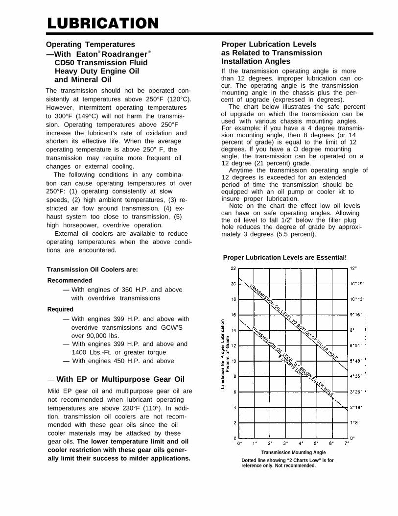
Proper Lubrication Levelsas Related to TransmissionInstallation AnglesIf the transmission operating angle is morethan 12 degrees, improper lubrication can oc-cur. The operating angle is the transmissionmounting angle in the chassis plus the per-cent of upgrade (expressed in degrees).
The chart below illustrates the safe percentof upgrade on which the transmission can beused with various chassis mounting angles.For example: if you have a 4 degree transmis-sion mounting angle, then 8 degrees (or 14percent of grade) is equal to the limit of 12degrees. If you have a O degree mountingangle, the transmission can be operated on a12 degree (21 percent) grade.
Anytime the transmission operating angle of12 degrees is exceeded for an extendedperiod of time the transmission should beequipped with an oil pump or cooler kit toinsure proper lubrication.
Note on the chart the effect low oil levelscan have on safe operating angles. Allowingthe oil level to fall 1/2” below the filler plughole reduces the degree of grade by approxi-mately 3 degrees (5.5 percent).
Proper Lubrication Levels are Essential!
Transmission Mounting Angle
Dotted line showing “2 Charts Low” is forreference only. Not recommended.
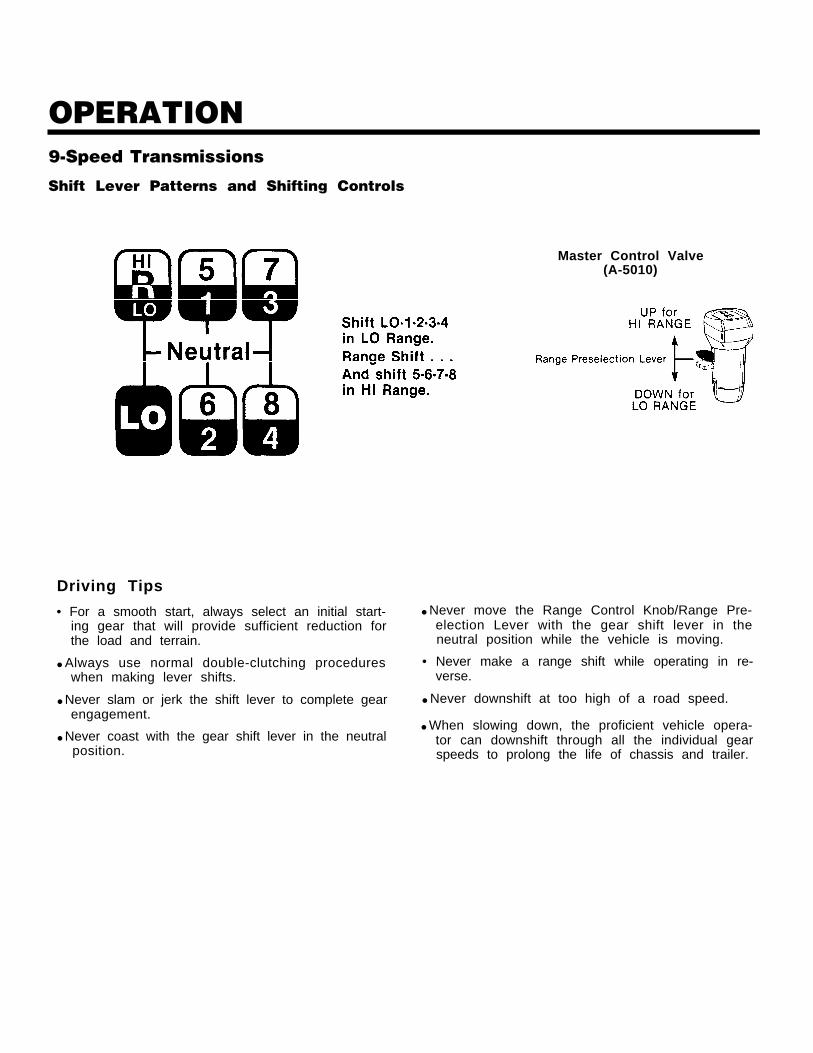
OPERATION9-Speed Transmissions
Shift Lever Patterns and Shifting Controls
Driving Tips
• For a smooth start, always select an initial start-ing gear that will provide sufficient reduction forthe load and terrain.
● Always use normal double-clutching procedureswhen making lever shifts.
● Never slam or jerk the shift lever to complete gearengagement.
● Never coast with the gear shift lever in the neutralposition.
Master Control Valve(A-5010)
● Never move the Range Control Knob/Range Pre-election Lever with the gear shift lever in theneutral position while the vehicle is moving.
• Never make a range shift while operating in re-verse.
● Never downshift at too high of a road speed.
● When slowing down, the proficient vehicle opera-tor can downshift through all the individual gearspeeds to prolong the life of chassis and trailer.

POWER FLOWThe transmission must efficiently transfer the engine’s power, in terms of torque, to the vehicle’s rear wheels.Knowledge of what takes place in the transmission during torque transfer is essential when trouble-shootingand making repairs.
Front Section Power Flow(All Models)
1.
2.
3.
4.
5.
6.
Power (torque) from the vehicle’s engine is trans- 7.ferred to the transmission’s input shaft.Splines of input shaft engage internal splines in 8.hub of main drive gear.Torque is split between the two countershaftdrive gears. 9.Torque is delivered along both countershaft tomating countershaft gears of “engaged” main- 1 0 .shaft gear. The following cross section views(Figures 1-3) illustrate a 1st/5th speed gear en-gagement.Internal clutching teeth in hub of engaged main-shaft gear transfers torque to mainshaft throughsliding clutch.Mainshaft transfers torque directly to auxiliarydrive gear.
The auxiliary drive gear splits torque between thetwo auxiliary countershaft drive gears.Torque is delivered along both auxiliary counter-shaft to the mating “engaged” gear on outputshaft.Torque is transferred to output shaft through slid-ing clutch.Output shaft delivers torque to driveline.
Cut 8006 B-6/87
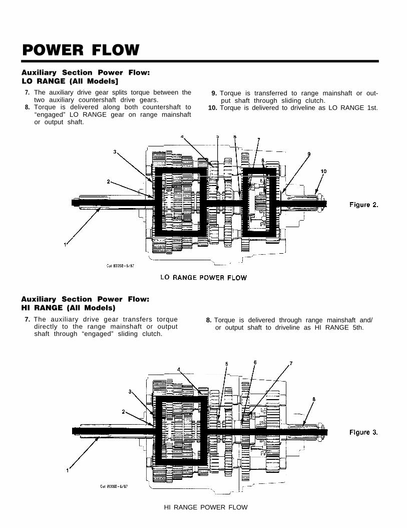
POWER FLOWAuxiliary Section Power Flow:LO RANGE (All Models]
7.
8.
The auxiliary drive gear splits torque between the 9. Torque is transferred to range mainshaft or out-two auxiliary countershaft drive gears. put shaft through sliding clutch.Torque is delivered along both countershaft to 10. Torque is delivered to driveline as LO RANGE 1st.“engaged” LO RANGE gear on range mainshaftor output shaft.
Auxiliary Section Power Flow:HI RANGE (All Models)7. The auxiliary drive gear transfers torque 8. Torque is delivered through range mainshaft and/
directly to the range mainshaft or output or output shaft to driveline as HI RANGE 5th.shaft through “engaged” sliding clutch.
HI RANGE POWER FLOW
TIMINGTiming Procedures: All ModelsIt is essential that both countershaft assemblies ofthe front and auxiliary sections are “timed. ” This as-sures proper tooth contact is made between main-shaft gears seeking to center on the mainshaftduring torque transfer and mating countershaft gearsthat distribute the load evenly. If not properly timed,serious damage to the transmission is likely to resultfrom unequal tooth contact causing the mainshaftgears to climb out of equilibrium.
Timing is a simple procedure of marking the appro-priate teeth of a gear set prior to installation andplacing them in proper mesh while in the transmis-sion. In the front section, it is necessary to time onlythe drive gear set. And depending on the model, onlythe LO range, deep reduction, or splitter gear set istimed in the auxiliary section.
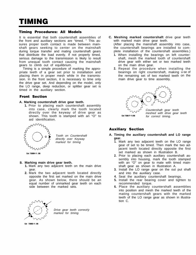
Front SectionA. Marking countershaft drive gear teeth.
1. Prior to placing each countershaft assemblyinto case, clearly mark the tooth locateddirectly over the keyway of drive gear asshown. This tooth is stamped with an “O” toaid identification.
B.
Tooth on Countershaftdirectly over Keywaymarked for timing
Cut 7300H-11 /86
Marking main drive gear teeth.1. Mark any two adjacent teeth on the main drive
gear.2. Mark the two adjacent teeth located directly
opposite the first set marked on the main drivegear. As shown below, there should be anequal number of unmarked gear teeth on eachside between the marked sets.
Drive gear teeth correct/ymarked for timing.
C. Meshing marked countershaft drive gear teethwith marked main drive gear teeth.(After placing the mainshaft assembly into case,the countershaft bearings are installed to com-plete installation of the countershaft assemblies.)1.
2.
When installing the bearings on left counter:shaft, mesh the marked tooth of countershaftdrive gear with either set or two marked teethon the main drive gear.Repeat the procedure when installing thebearings on right countershaft, makingthe remaining set of two marked teethmain drive gear to time assembly.
u-se ofon the
Cut 7300 F-11/86
Auxiliary Section
_ _
Countershaft gear teethmeshed with drive gear teethfor correct timing.
A. Timing the auxiliary countershaft and LO rangegear.1.
2.
3.
4.5.
6.
Mark any two adjacent teeth on the LO rangegear of set to be timed. Then mark the two ad-jacent teeth located directly opposite the firstset marked as shown in Illustration B.Prior to placing each auxiliary countershaft as-sembly into housing, mark the tooth stampedwith an “O” on gear to mate with timed main-shaft gear as shown in Illustration A.Install the LO range gear on the out put shaftand into the auxiliary case.Seat the auxiliary countershaft bearings.Install the rear bearing cover and tighten torecommended torque.Place the auxiliary countershaft assembliesinto position and mesh the marked teeth of themating countershaft gears with the markedteeth of the LO range gear as shown in illustra-tion C.
Cut 7300G-11 /86
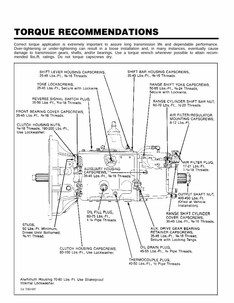
TORQUE RECOMMENDATIONSCorrect torque application is extremely important to assure long transmission life and dependable performance.Over-tightening or under-tightening can result in a loose installation and, in many instances, eventually causedamage to transmission gears, shafts, and/or bearings. Use a torque wrench whenever possible to attain recom-mended lbs./ft. ratings. Do not torque capscrews dry.
Cut 7190J-5/87
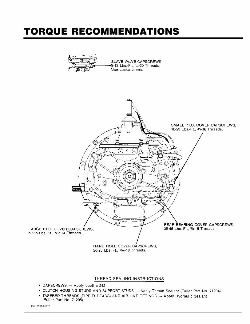
TORQUE RECOMMENDATIONS
Cut 7191J-5/87
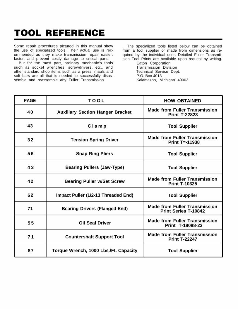
TOOL REFERENCESome repair procedures pictured in this manual showthe use of specialized tools. Their actual use is rec-ommended as they make transmission repair easier,faster, and prevent costly damage to critical parts.
But for the most part, ordinary mechanic’s toolssuch as socket wrenches, screwdrivers, etc., andother standard shop items such as a press, mauls andsoft bars are all that is needed to successfully disas-semble and reassemble any Fuller Transmission.
The specialized tools listed below can be obtainedfrom a tool supplier or made from dimensions as re-quired by the individual user. Detailed Fuller Transmit-sion Tool Prints are available upon request by writing.
Eaton CorporationTransmission DivisionTechnical Service Dept.P.O. Box 4013Kalamazoo, Michigan 49003
PAGE T O O L HOW OBTAINED
40 Auxiliary Section Hanger Bracket Made from Fuller TransmissionPrint T-22823
43 C l a m p Tool Supplier
3 2 Tension Spring Driver Made from Fuller TransmissionPrint T=-11938
5 6 Snap Ring Pliers Tool Supplier
4 3 Bearing Pullers (Jaw-Type) Tool Supplier
42 Bearing Puller w/Set Screw Made from Fuller TransmissionPrint T-10325
62 Impact Puller (1/2-13 Threaded End) Tool Supplier
71 Bearing Drivers (Flanged-End) Made from Fuller TransmissionPrint Series T-10842
5 5 Oil Seal Driver Made from Fuller TransmissionPrint T-18088-23
7 1 Countershaft Support Tool Made from Fuller TransmissionPrint T-22247
87 Torque Wrench, 1000 Lbs./Ft. Capacity Tool Supplier
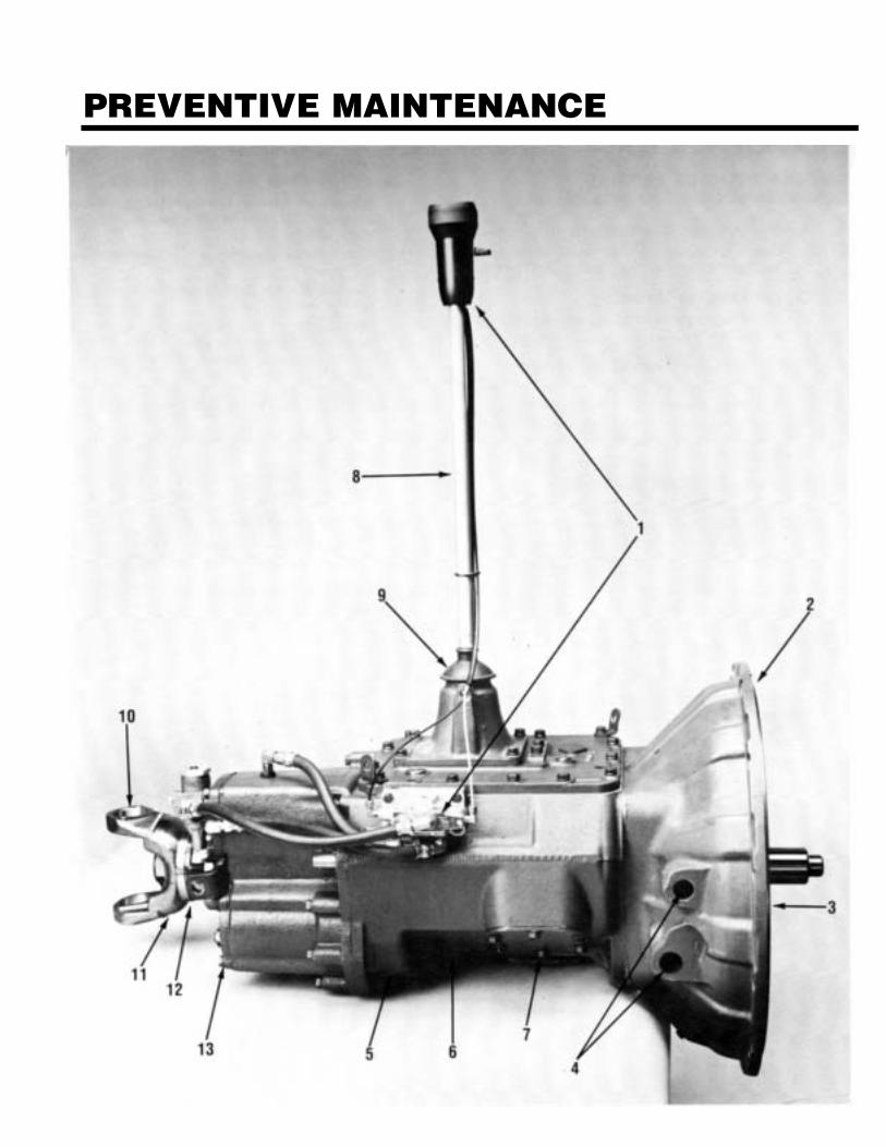
PREVENTIVE MAINTENANCE
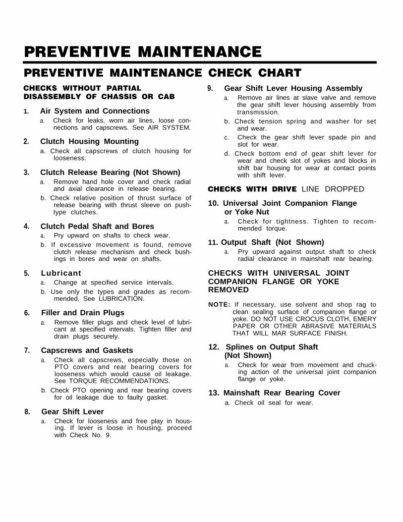
PREVENTIVE MAINTENANCEPREVENTIVE MAINTENANCE CHECK CHARTCHECKS WITHOUT PARTIALDISASSEMBLY OF CHASSIS OR CAB
1.
2.
3.
4.
5.
6.
7.
8.
Air System and Connectionsa. Check for leaks, worn air lines, loose con-
nections and capscrews. See AIR SYSTEM.
Clutch Housing Mountinga. Check all capscrews of clutch housing for
looseness.
Clutch Release Bearing (Not Shown)a. Remove hand hole cover and check radial
and axial clearance in release bearing.b. Check relative position of thrust surface of
release bearing with thrust sleeve on push-type clutches.
Clutch Pedal Shaft and Boresa. Pry upward on shafts to check wear.b. If excessive movement is found, remove
clutch release mechanism and check bush-ings in bores and wear on shafts.
Lubricanta. Change at specified service intervals.b. Use only the types and grades as recom-
mended. See LUBRICATION.
Filler and Drain Plugsa. Remove filler plugs and check level of lubri-
cant at specified intervals. Tighten filler anddrain plugs securely.
Capscrews and Gasketsa. Check all capscrews, especially those on
PTO covers and rear bearing covers forlooseness which would cause oil leakage.See TORQUE RECOMMENDATIONS.
b. Check PTO opening and rear bearing coversfor oil leakage due to faulty gasket.
Gear Shift Levera. Check for looseness and free play in hous-
ing. If lever is loose in housing, proceedwith Check No. 9.
9. Gear Shift Lever Housing Assemblya. Remove air lines at slave valve and remove
the gear shift lever housing assembly fromtransmission.
b. Check tension spring and washer for setand wear.
c. Check the gear shift lever spade pin andslot for wear.
d. Check bottom end of gear shift lever forwear and check slot of yokes and blocks inshift bar housing for wear at contact pointswith shift lever.
CHECKS WITH DRIVE LINE DROPPED
10. Universal Joint Companion Flangeor Yoke Nuta. Check for tightness. Tighten to recom-
mended torque.
11. Output Shaft (Not Shown)a. Pry upward against output shaft to check
radial clearance in mainshaft rear bearing.
CHECKS WITH UNIVERSAL JOINTCOMPANION FLANGE OR YOKEREMOVED
NOTE: If necessary, use solvent and shop rag toclean sealing surface of companion flange oryoke. DO NOT USE CROCUS CLOTH, EMERYPAPER OR OTHER ABRASIVE MATERIALSTHAT WILL MAR SURFACE FINISH.
12. Splines on Output Shaft(Not Shown)a. Check for wear from movement and chuck-
ing action of the universal joint companionflange or yoke.
13. Mainshaft Rear Bearing Covera. Check oil seal for wear.
14
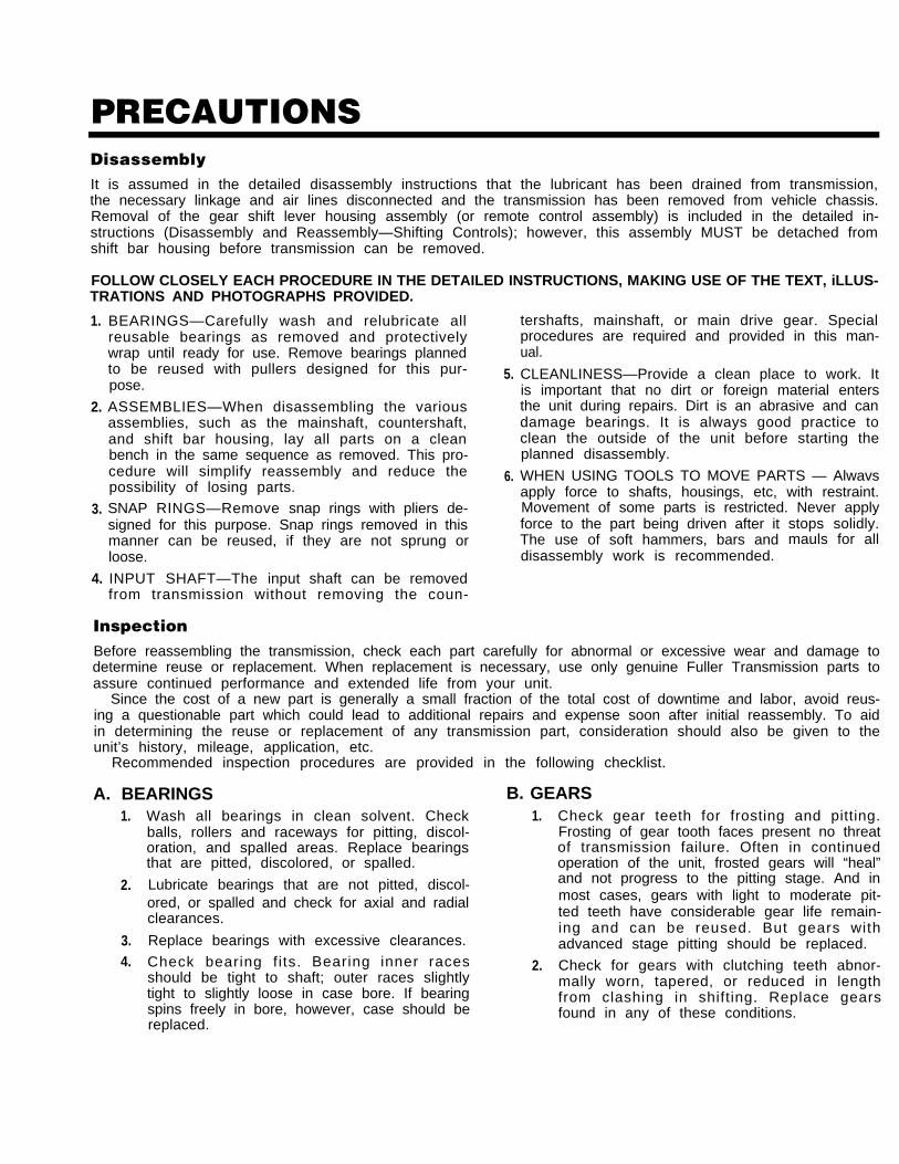
PRECAUTIONSDisassemblyIt is assumed in the detailed disassembly instructions that the lubricant has been drained from transmission,the necessary linkage and air lines disconnected and the transmission has been removed from vehicle chassis.Removal of the gear shift lever housing assembly (or remote control assembly) is included in the detailed in-structions (Disassembly and Reassembly—Shifting Controls); however, this assembly MUST be detached fromshift bar housing before transmission can be removed.
FOLLOW CLOSELY EACH PROCEDURE IN THE DETAILED INSTRUCTIONS, MAKING USE OF THE TEXT, iLLUS-TRATIONS AND PHOTOGRAPHS PROVIDED.
1.
2.
3.
4.
BEARINGS—Carefully wash and relubricate allreusable bearings as removed and protectivelywrap until ready for use. Remove bearings plannedto be reused with pullers designed for this pur-pose.
ASSEMBLIES—When disassembling the variousassemblies, such as the mainshaft, countershaft,and shift bar housing, lay all parts on a cleanbench in the same sequence as removed. This pro-cedure will simplify reassembly and reduce thepossibility of losing parts.
SNAP RINGS—Remove snap rings with pliers de-signed for this purpose. Snap rings removed in thismanner can be reused, if they are not sprung orloose.
INPUT SHAFT—The input shaft can be removed
5.
6.
tershafts, mainshaft, or main drive gear. Specialprocedures are required and provided in this man-ual.
CLEANLINESS—Provide a clean place to work. Itis important that no dirt or foreign material entersthe unit during repairs. Dirt is an abrasive and candamage bearings. It is always good practice toclean the outside of the unit before starting theplanned disassembly.
WHEN USING TOOLS TO MOVE PARTS — Alwavsapply force to shafts, housings, etc, with restraint.Movement of some parts is restricted. Never applyforce to the part being driven after itThe use of soft hammers, bars anddisassembly work is recommended.
stops solidly.mauls for all
from transmission without removing the coun-
InspectionBefore reassembling the transmission, check each part carefully for abnormal or excessive wear and damage todetermine reuse or replacement. When replacement is necessary, use only genuine Fuller Transmission parts toassure continued performance and extended life from your unit.
Since the cost of a new part is generally a small fraction of the total cost of downtime and labor, avoid reus-ing a questionable part which could lead to additional repairs and expense soon after initial reassembly. To aidin determining the reuse or replacement of any transmission part, consideration should also be given to theunit’s history, mileage, application, etc.
Recommended inspection procedures are provided in the following checklist.
A. BEARINGS B. GEARS1.
2.
3.4.
Wash all bearings in clean solvent. Check 1.balls, rollers and raceways for pitting, discol-oration, and spalled areas. Replace bearingsthat are pitted, discolored, or spalled.
Lubricate bearings that are not pitted, discol-ored, or spalled and check for axial and radialclearances.
Replace bearings with excessive clearances.
Check bearing f i ts. Bearing inner races 2.should be tight to shaft; outer races slightlytight to slightly loose in case bore. If bearingspins freely in bore, however, case should bereplaced.
Check gear teeth for frosting and pitting.Frosting of gear tooth faces present no threatof transmission failure. Often in continuedoperation of the unit, frosted gears will “heal”and not progress to the pitting stage. And inmost cases, gears with light to moderate pit-ted teeth have considerable gear life remain-ing and can be reused. But gears withadvanced stage pitting should be replaced.
Check for gears with clutching teeth abnor-mally worn, tapered, or reduced in lengthfrom clashing in shifting. Replace gearsfound in any of these conditions.
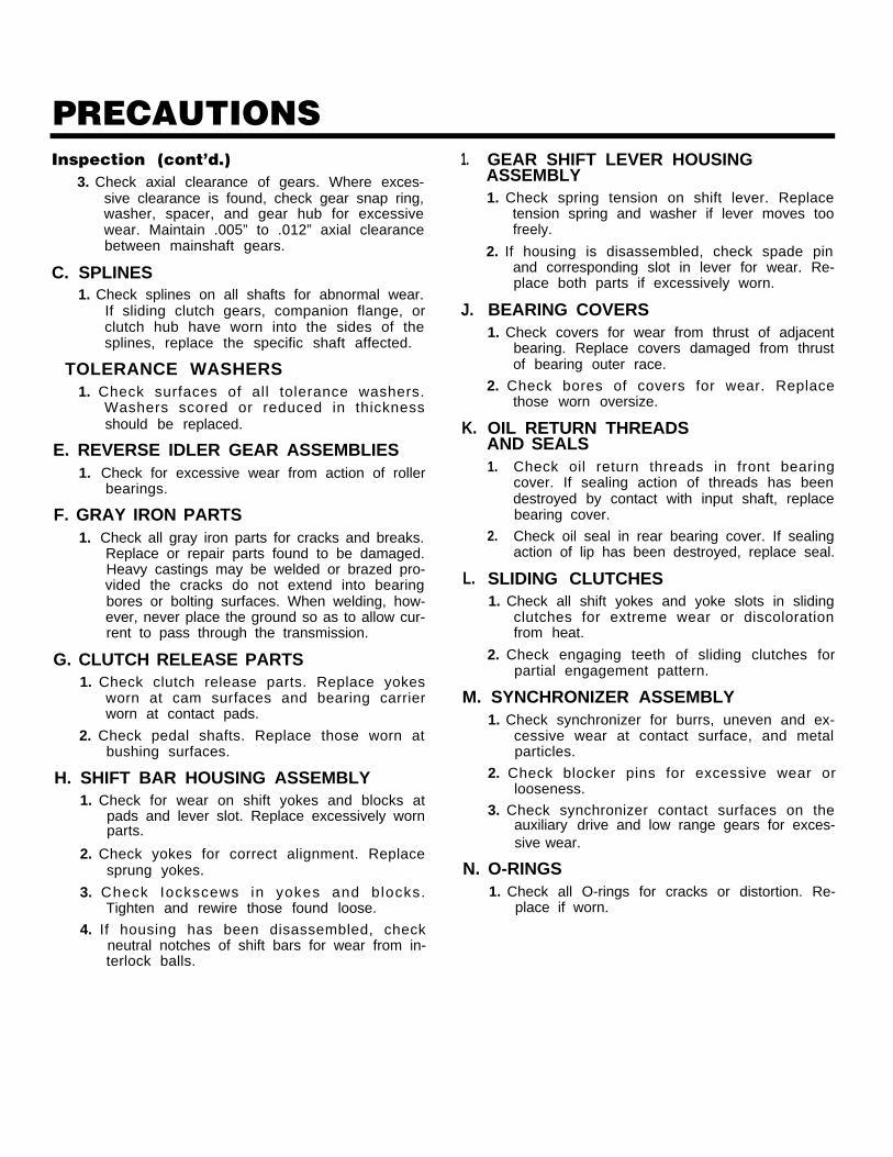
PRECAUTIONSInspection (cont’d.)
3. Check axial clearance of gears. Where exces-sive clearance is found, check gear snap ring,washer, spacer, and gear hub for excessivewear. Maintain .005” to .012” axial clearancebetween mainshaft gears.
C. SPLINES1. Check splines on all shafts for abnormal wear.
If sliding clutch gears, companion flange, orclutch hub have worn into the sides of thesplines, replace the specific shaft affected.
TOLERANCE WASHERS1. Check surfaces of all tolerance washers.
Washers scored or reduced in thicknessshould be replaced.
E. REVERSE IDLER GEAR ASSEMBLIES1. Check for excessive wear from action of roller
bearings.
F. GRAY IRON PARTS1. Check all gray iron parts for cracks and breaks.
Replace or repair parts found to be damaged.Heavy castings may be welded or brazed pro-vided the cracks do not extend into bearingbores or bolting surfaces. When welding, how-ever, never place the ground so as to allow cur-rent to pass through the transmission.
G. CLUTCH RELEASE PARTS1. Check clutch release parts. Replace yokes
worn at cam surfaces and bearing carrierworn at contact pads.
2. Check pedal shafts. Replace those worn atbushing surfaces.
H. SHIFT BAR HOUSING ASSEMBLY1. Check for wear on shift yokes and blocks at
pads and lever slot. Replace excessively wornparts.
2. Check yokes for correct alignment. Replacesprung yokes.
3. Check Iockscews in yokes and blocks.Tighten and rewire those found loose.
4. If housing has been disassembled, checkneutral notches of shift bars for wear from in-terlock balls.
1.
J.
K.
L.
GEAR SHIFT LEVER HOUSINGASSEMBLY1. Check spring tension on shift lever. Replace
tension spring and washer if lever moves toofreely.
2. If housing is disassembled, check spade pinand corresponding slot in lever for wear. Re-place both parts if excessively worn.
BEARING COVERS1. Check covers for wear from thrust of adjacent
bearing. Replace covers damaged from thrustof bearing outer race.
2. Check bores of covers for wear. Replacethose worn oversize.
OIL RETURN THREADSAND SEALS1.
2.
Check oil return threads in front bearingcover. If sealing action of threads has beendestroyed by contact with input shaft, replacebearing cover.
Check oil seal in rear bearing cover. If sealingaction of lip has been destroyed, replace seal.
SLIDING CLUTCHES1. Check all shift yokes and yoke slots in sliding
clutches for extreme wear or discolorationfrom heat.
2. Check engaging teeth of sliding clutches forpartial engagement pattern.
M. SYNCHRONIZER ASSEMBLY1. Check synchronizer for burrs, uneven and ex-
cessive wear at contact surface, and metalparticles.
2. Check blocker pins for excessive wear orlooseness.
3. Check synchronizer contact surfaces on theauxiliary drive and low range gears for exces-sive wear.
N. O-RINGS1. Check all O-rings for cracks or distortion. Re-
place if worn.
PRECAUTIONSReassemblyMake sure that interiors of case and housings are clean. It is important that dirt and other foreign materials bekept out of the transmission during reassembly. Dirt is an abrasive and can damage polished surfaces of‘bearings and washers. Use certain precautions, as listed below, during reassembly.
1.
2.
3.
4.
5.
GASKETS — Use new gaskets throughout thetransmission as it is being rebuilt. Make sure allgaskets are installed. An omission of any gasketcan result in oil leakage or misalignment ofbearing covers.
CAPSCREWS — TO prevent oil leakage, use Loctite242 thread sealant on all capscrews. For torqueratings, see TORQUE RECOMMENDATIONS.
O-RINGS — Lubricate all O-rings with silicone lu-bricant.
ASSEMBLY — Refer to the illustrations provided inthe detailed disassembly instructions as a guideto reassembly.
INITIAL LUBRICATION — Coat all limit washersand splines of shafts with Lubriplate during reas-sembly to prevent scoring and galling of suchparts.
6.
7.
8.
AXIAL CLEARANCES — Maintain original axialclearances of .005” to .012” for mainshaft gears.
BEARINGS — Use of flanged-end bearing drivers isrecommended for the installation of bearings.These special drivers apply equal force to bothbearing races, preventing damage to balls/rollersand races while maintaining correct bearing align-ment with bore and shaft. Avoid using a tubular orsleeve-type driver, whenever possible, as force isapplied to only one of the bearing races. SeeTOOL REFERENCE.
UNIVERSAL JOINT COMPANION FLANGE ORYOKE — Pull the companion flange or yoke tightlyinto place with the output shaft nut, using 450-500foot-pounds of torque. Make sure the speedome-ter drive gear or a replacement spacer of the samewidth has been installed. Failure to pull the com-panion flange or yoke tightly into place will permitthe output shaft to move axially with resultantdamage to the rear bearing.
IMPORTANT: REFER TO THE APPROPRIATE ILLUSTRATED PARTS LIST (SPECI-FIED BY MODEL SERIES) TO ENSURE THAT PROPER PARTS AREUSED DURING REASSEMBLY OF THE TRANSMISSION.
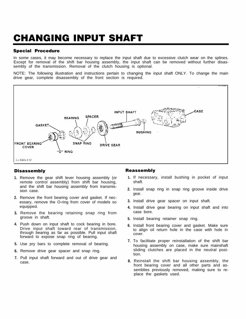
CHANGING INPUT SHAFTSpecial ProcedureIn some cases, it may become necessary to replace the input shaft due to excessive clutch wear on the splines.Except for removal of the shift bar housing assembly, the input shaft can be removed without further disas-sembly of the transmission. Removal of the clutch housing is optional.
NOTE: The following illustration and instructions pertain to changing the input shaft ONLY. To change the maindrive gear, complete disassembly of the front section is required.
Disassembly1.
2.
3.
4.
5.
6.
7.
Remove the gear shift lever housing assembly (orremote control assembly) from shift bar housing,and the shift bar housing assembly from transmis-sion case.
Remove the front bearing cover and gasket. If nec-essary, remove the O-ring from cover of models soequipped.
Remove the bearing retaining snap ring fromgroove in shaft.
Push down on input shaft to cock bearing in bore.Drive input shaft toward rear of transmission,through bearing as far as possible. Pull input shaftforward to expose snap ring of bearing.
Use pry bars to complete removal of bearing.
Remove drive gear spacer and snap ring.
Pull input shaft forward and out of drive gear andcase.
Reassembly1.
2.
3.
4.
5.
6.
7.
8.
If necessary, install bushing in pocket of inputshaft.
Install snap ring in snap ring groove inside drivegear.
Install drive gear spacer on input shaft.
Install drive gear bearing on input shaft and intocase bore.
Install bearing retainer snap ring.
Install front bearing cover and gasket. Make sureto align oil return hole in the case with hole incover.
To facilitate proper reinstallation of the shift barhousing assembly on case, make sure mainshaftsliding clutches are placed in the neutral posi-tion.
Reinstall the shift bar housing assembly, thefront bearing cover and all other parts and as-semblies previously removed, making sure to re-place the gaskets used.
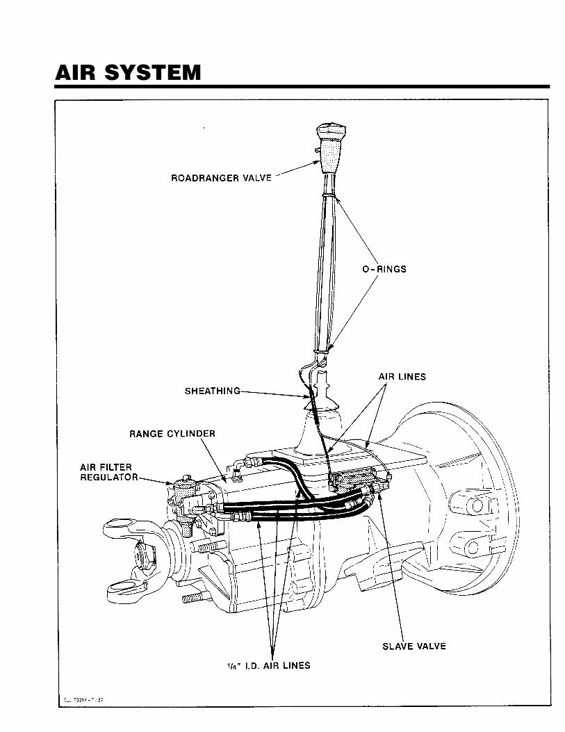
AIR SYSTEM
AIR SYSTEMRANGE SHIFT AIR SYSTEM—ALL MODELSOperationThe Range Shift Air System consists of the air filter/regulator, slave valve, a Range Control Valve or Mas-ter Control Valve, range cylinder, f i t t ings andconnecting air lines. See Air System Schematics.
CONSTANT AIR from the air filter/regulator is sup-plied to the “S” or Supply Port of slave valve andpassed through to the INLET or “S” Port of controlvalve.
WHILE IN LO RANGE, the control valve is OPENand AIR is returned to slave valve at the “P” or EndPort. This signals the valve to supply AIR in line be-tween the Lo Range or “L” Port of slave valve and theLo Range Port of range cylinder housing. AIR re-ceived at this port moves the range piston to the rearand causes the auxiliary LO RANGE gear to becomeengaged.
WHILE IN HI RANGE, the control valve is CLOSEDand NO AIR is returned to the slave valve. Thissignals the slave valve to supply AIR in line betweenthe HI Range or “H” Port of valve and the HI RangePort of range cylinder cover. AIR received at this portmoves the range piston forward to engage the aux-iliary drive gear with sliding clutch and bypass theLO RANGE gear set.
Range shifts can be made ONLY when the gearshift lever is in, or passing through, neutral. Thus, therange desired can be PRESELECTED while the shiftlever is in a gear position. As the lever is movedthrough neutral, the actuating plunger in the shift barhousing releases the slave valve, allowing it to moveto the selected range position.
Trouble ShootingIf the transmission fails to make a range shift orshifts too slowly, the fault may be in the Range ShiftAir System or actuating components of the shift barhousing assembly.
To locate the trouble, the following checks shouldbe made with normal vehicle air pressure applied tothe system, but with the engine off.
CAUTION: NEVER WORK UNDERA VEHICLE WHILE ENGINE IS
RUNNING as personal injury may result from thesudden and unintended movement of vehicle underpower. Always place transmission in the neutral posi-tion.
1. INCORRECT AIR LINE HOOK-UPS(See Air System Schematics)With the gear shift lever in neutral, move the con-trol that provides range selection UP and DOWN.A. If the air lines are crossed between control
valve and slave valve, there will be CON-STANT AIR flowing from the exhaust port ofcontrol valve WHILE IN HI RANGE.
2.
3.
4.
B. If the air lines are crossed between the slavevalve and range cylinder, the transmissiongearing will not correspond with the range se-lection. A LO RANGE selection will result in aHI RANGE engagement and vice versa.
AIR LEAKSWith the gear shift lever in neutral, coat all airlines and fittings with soapy water and check forleaks, moving the control that provides range se-lection UP and DOWN.
A.
B.
C.
D.
If there is a steady leak from the exhaust portof control valve, O-rings and/or related partsof the control valve are defective.
If there is a steady leak from breather of slavevalve: an O-ring in valve is defective, or thereis a leak past O-rings of range cylinder piston.
If transmission fails to shift into LO RANGEor is slow to make the range shift and thecase is pressurized, see Check No. 7 of thissection.
Tighten all loose connections and replace de-fective O-rings and parts.
AIR FILTER/REGULATOR(See illustration, Page 22.)With the gear shift Iever in neutral, check thebreather of air filter/regulator assembly. Thereshould be NO AIR leaking from this port. Thecomplete assembly should be replaced if asteady leak is found.
Cut off the vehicle air supply to the air filter/regulator assembly, disconnect the air line at fit-ting in Supply OUTLET and install an air gage inopened port. Bring the vehicle air pressure to nor-mal. Regulated air pressure should be 57.5 to 62.5Psi.
DO NOT ADJUST SCREW AT BOTTOM OF REGU-LATOR TO OBTAIN CORRECT READINGS. Theair regulator has been PREADJUSTED within thecorrect operating limits. Any deviation from theselimits, especially with regulators that have beenin operation for some time, is likely to be causedby dirt or worn parts. If replacement or cleaningof the filter element does nothing to correct theair pressure readings, replace the complete as-sembly, as the air regulator is nonserviceable.
RANGE VALVE (See Page 23.)With the gear shift lever in neutral, select HIRANGE and disconnect the air line at the OUT-LET or “P” Port of control valve.
AIR SYSTEMA. When LO RANGE is selected, a steady blast
of air will flow from opened port. Select HIRANGE to shut off air flow. This indicates thecontrol valve is operating properly. Reconnectair line.
B. If control valve does not operate properly,check for restrictions and air leaks. Leaks in-dicate defective or worn O-rings.
5. HI RANGE OPERATIONWith the gear shift lever in neutral, select LORANGE and disconnect the 1/4” I.D. air line at theport of range cylinder cover. Make sure this lineleads from the HI Range or “H” Port of slavevalve.
A. When HI RANGE is selected, a steady blast ofair should flow from disconnected line. SelectLO RANGE to shut off air flow.
B. Move the shift lever to a gear position and se-lect HI RANGE. There should be NO AIR flow-ing from disconnected line. Return the gearshift lever to the neutral position. Thereshould now be a steady flow of air from dis-connected line. Select LO RANGE to shut offair flow and reconnect air line.
C. If the air system does not operate accord-ingly, the slave valve or actuating componentsof the shift bar housing assembly are defec-tive.
IMPORTANT: RANGE PRESELECTIONThe plunger pin, located in case bore betweenthe slave valve and actuating plunger of shift barhousing, prevents the slave valve from operatingwhile the shift lever is in a gear position. Whenthe lever is moved to or through the neutral po-sition, the pin is released and the slave valve be-comes operational.
6. LO RANGE OPERATIONWith the gear shift lever in neutral, select HIRANGE and disconnect the 1/4” I.D. air line at thefitting on range cylinder housing. Make sure thisline leads from the Lo Range or “L” Port of slavevalve.
A. When LO RANGE is selected, a steady blastof air should flow from disconnected line. Se-lect HI RANGE to shut off air flow.
B. Move the shift lever to a gear position and se-lect LO RANGE. There should be NO AIR flo-wing from disconnected line. Return the gearshift lever to the neutral position. Thereshould now be a steady flow of air from dis-connected line. Select HI RANGE to shut offair flow and reconnect air line.
C. If the air system does not operate accord-ingly, the slave valve or actuating componentsof the shift bar housing assembly are defec-tive.
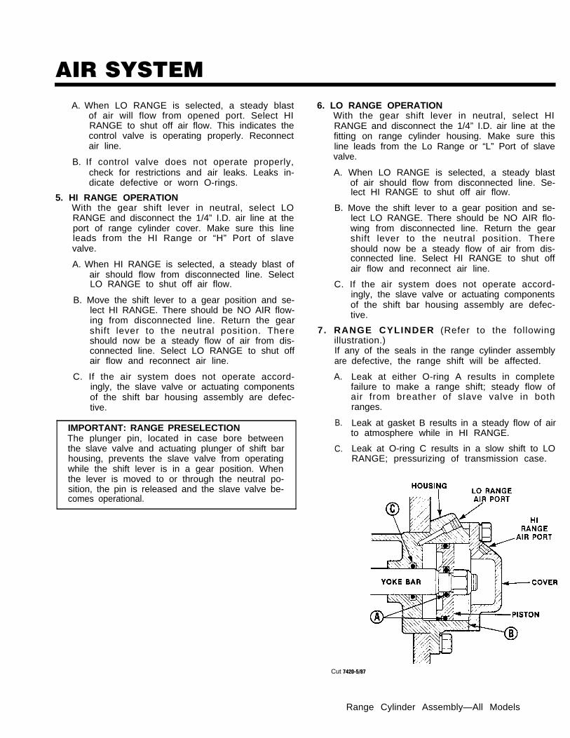
7. RANGE CYLINDER (Refer to the followingillustration.)If any of the seals in the range cylinder assemblyare
A.
B.
C.
defective, the range shift will be affected.
Leak at either O-ring A results in completefailure to make a range shift; steady flow ofair from breather of slave valve in bothranges.
Leak at gasket B results in a steady flow of airto atmosphere while in HI RANGE.
Leak at O-ring C results in a slow shift to LORANGE; pressurizing of transmission case.
Cut 7420-5/87
Range Cylinder Assembly—All Models
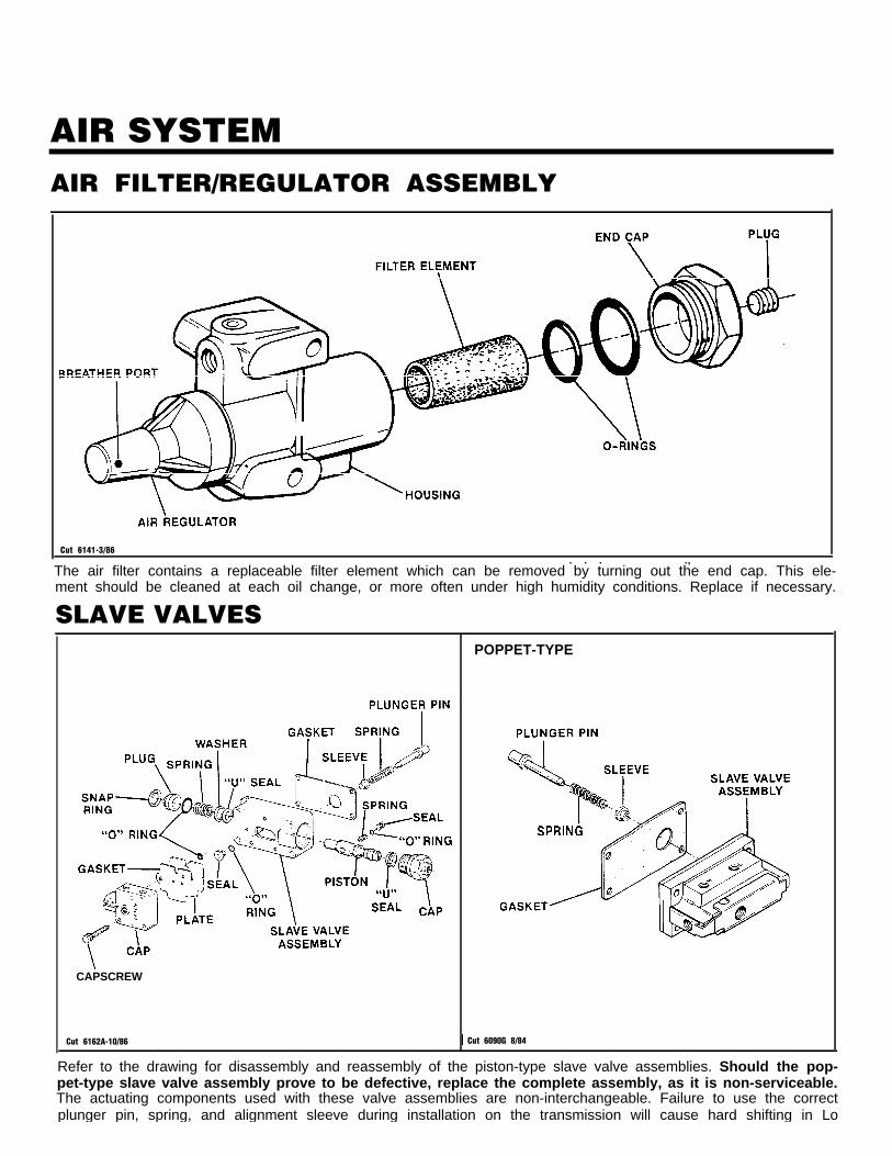
AIR SYSTEMAIR FILTER/REGULATOR ASSEMBLY
Cut 6141-3/86. . . .,
The air filter contains a replaceable filter element which can be removed by turning out the end cap. This ele-ment should be cleaned at each oil change, or more often under high humidity conditions. Replace if necessary.
SLAVE VALVES
CAPSCREW
POPPET-TYPE
Cut 6162A-10/86 Cut 6090G 8/84
Refer to the drawing for disassembly and reassembly of the piston-type slave valve assemblies. Should the pop-pet-type slave valve assembly prove to be defective, replace the complete assembly, as it is non-serviceable.The actuating components used with these valve assemblies are non-interchangeable. Failure to use the correctplunger pin, spring, and alignment sleeve during installation on the transmission will cause hard shifting in Lo
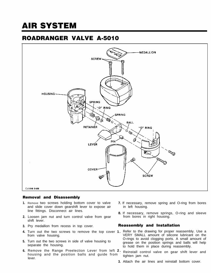
AIR SYSTEMROADRANGER VALVE A-5010
Cut 6146 G-4/86
Removal and Disassembly1.
2.
3.
4.
5.
6.
Remove two screws holding bottom cover to valve 7. If necessary, remove spring and O-ring from boresand slide cover down gearshift lever to expose air in left housing.line fittings. Disconnect air lines.
8. If necessary, remove springs, O-ring and sleeveLoosen jam nut and turn control valve from gear from bores in right housing.shift lever.
Pry medallion from recess in top cover. Reassembly and Installation
Turn out the two screws to remove the top cover 1 .from valve housing.
Turn out the two screws in side of valve housing toseparate the housing.
Remove the Range Preelection Lever from left 2 .housing and the posit ion balls and guide from -
lever.3.
Refer to the drawing for proper reassembly. Use aVERY SMALL amount of silicone lubricant on theO-rings to avoid clogging ports. A small amount ofgrease on the position springs and balls will helpto hold them in place during reassembly.
Reinstall control valve on gear shift lever andtighten jam nut.
Attach the air lines and reinstall bottom cover.
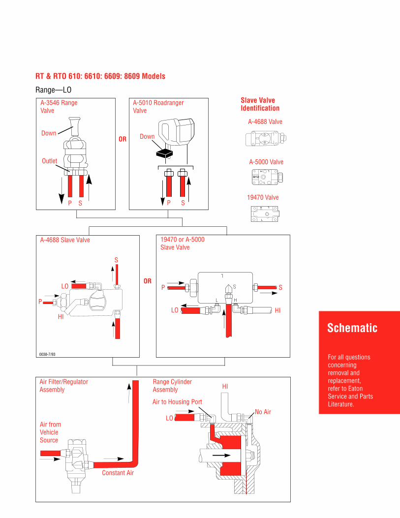
Schematic
For all questionsconcerningremoval andreplacement,refer to EatonService and PartsLiterature.
Air Filter/RegulatorAssembly
Range CylinderAssembly
Air fromVehicleSource
Constant Air
HI
No AirLO
Air to Housing Port
RT & RTO 610: 6610: 6609: 8609 Models
Range—LO
Down
A-3546 RangeValve
Outlet
P S
A-5010 RoadrangerValve
DownOR
SP
Slave ValveIdentification
A-4688 Valve
A-5000 Valve
19470 Valve
OR
0038-7/93
A-4688 Slave Valve 19470 or A-5000Slave Valve
P
S
SLO
HIHI
P
LO
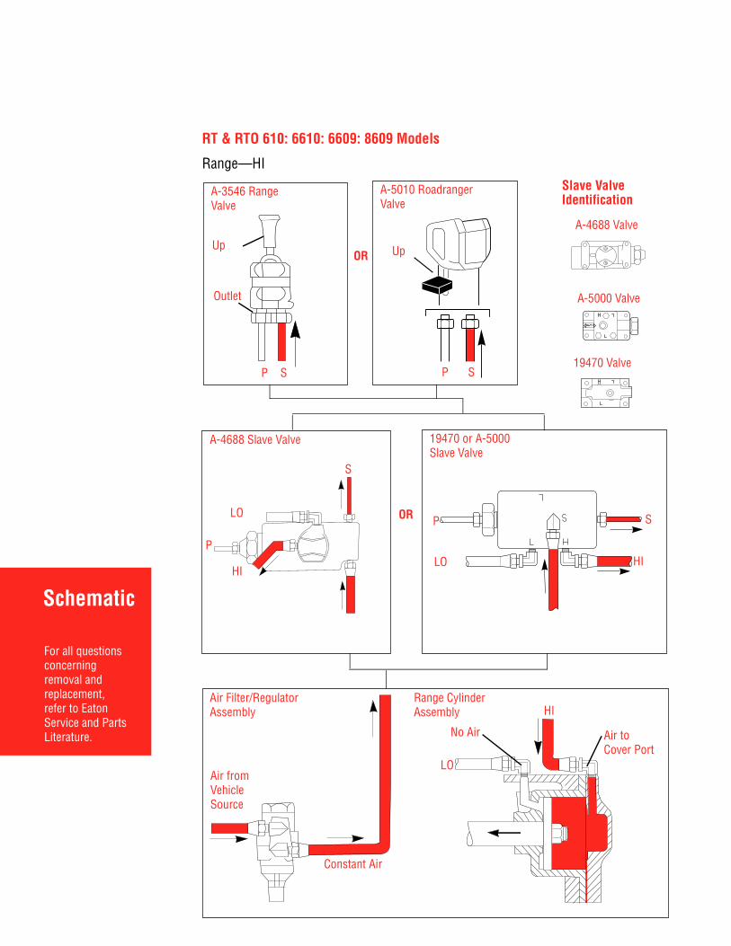
Schematic
For all questionsconcerningremoval andreplacement,refer to EatonService and PartsLiterature.
Air Filter/RegulatorAssembly
Air fromVehicleSource
Constant Air
Range CylinderAssembly
Up
Outlet
P S
UpOR
SP
A-3546 RangeValve
A-5010 RoadrangerValve
Slave ValveIdentification
A-4688 Valve
A-5000 Valve
19470 Valve
OR
A-4688 Slave Valve 19470 or A-5000Slave Valve
RT & RTO 610: 6610: 6609: 8609 Models
Range—HI
LO
No Air
HI
Air toCover Port
P
S
LO
HI
P
LO
S
HI
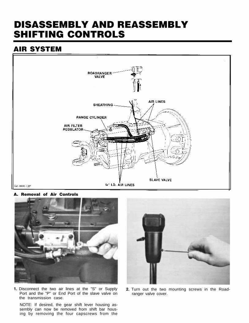
DISASSEMBLY AND REASSEMBLYSHIFTING CONTROLSAIR SYSTEM
A. Removal of Air Controls
1. Disconnect the two air lines at the "S" or Supply 2. Turn out the two mounting screws in the Road-Port and the "P" or End Port of the slave valve on ranger valve cover.the transmission case.
NOTE: If desired, the gear shift lever housing as-sembly can now be removed from shift bar hous-ing by removing the four capscrews from thet
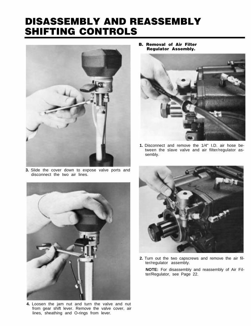
DISASSEMBLY AND REASSEMBLYSHIFTING CONTROLS
3. Slide the cover down to expose valve ports anddisconnect the two air lines.
B. Removal of Air FilterRegulator Assembly.
1. Disconnect and remove the 1/4" I.D. air hose be-tween the slave valve and air filter/regulator as-sembly.
2. Turn out the two capscrews and remove the air fil-ter/regulator assembly.
NOTE: For disassembly and reassembly of Air Fil-ter/Regulator, see Page 22.
4. Loosen the jam nut and turn the valve and nutfrom gear shift lever. Remove the valve cover, airlines, sheathing and O-rings from lever.
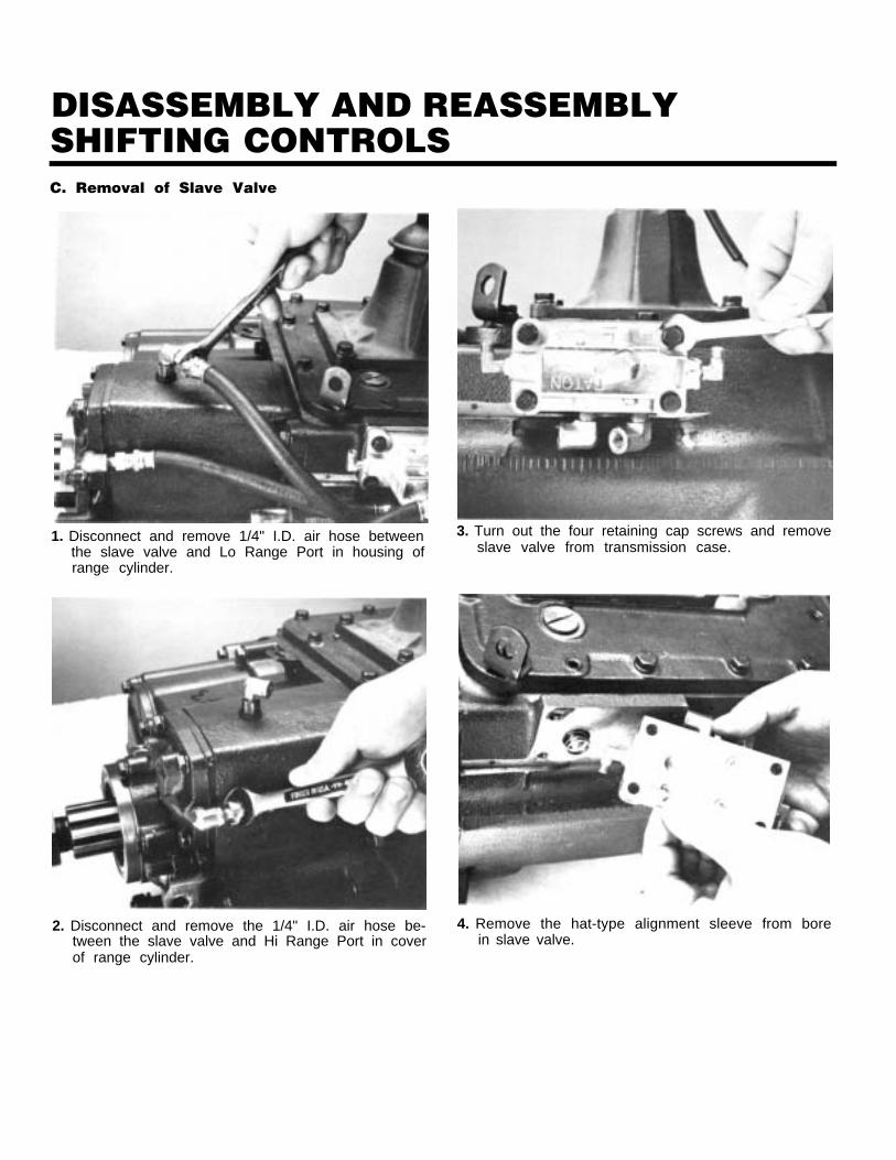
DISASSEMBLY AND REASSEMBLYSHIFTING CONTROLSC. Removal of Slave Valve
. .
1. Disconnect and remove 1/4" I.D. air hose betweenthe slave valve and Lo Range Port in housing ofrange cylinder.
2. Disconnect and remove the 1/4" I.D. air hose be-tween the slave valve and Hi Range Port in coverof range cylinder.
3. Turn out the four retaining cap screws and removeslave valve from transmission case.
4. Remove the hat-type alignment sleeve from borein slave valve.
DISASSEMBLY AND REASSEMBLYSHIFTING CONTROLS
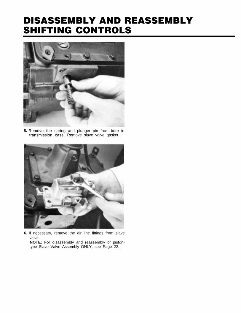
5. Remove the springtransmission case.
and plunger pin from bore inRemove slave valve gasket.
6. If necessary, remove the air line fittings from slavevalve.NOTE: For disassembly and reassembly of piston-type Slave Valve Assembly ONLY, see Page 22.
DISASSEMBLY AND REASSEMBLYSHIFTING CONTROLSGEAR SHIFT LEVER HOUSING ASSEMBLY
Cut 7288 D-2186
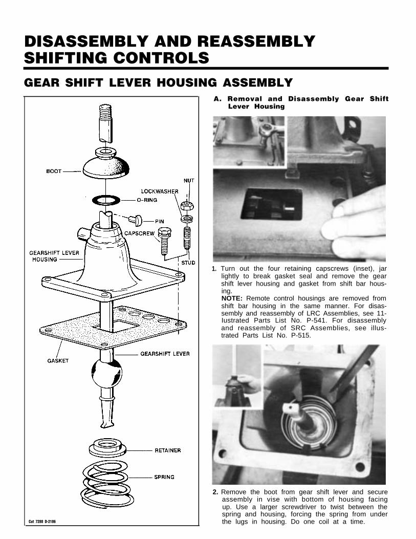
A. Removal and Disassembly Gear ShiftLever Housing
1. Turn out the four retaining capscrews (inset), jarlightly to break gasket seal and remove the gearshift lever housing and gasket from shift bar hous-ing.NOTE: Remote control housings are removed fromshift bar housing in the same manner. For disas-sembly and reassembly of LRC Assemblies, see 11-Iustrated Parts List No. P-541. For disassemblyand reassembly of SRC Assemblies, see illus-trated Parts List No. P-515.
2. Remove the boot from gear shift lever and secureassembly in vise with bottom of housing facingup. Use a larger screwdriver to twist between thespring and housing, forcing the spring from underthe lugs in housing. Do one coil at a time.
DISASSEMBLY AND REASSEMBLYSHIFTING CONTROLS
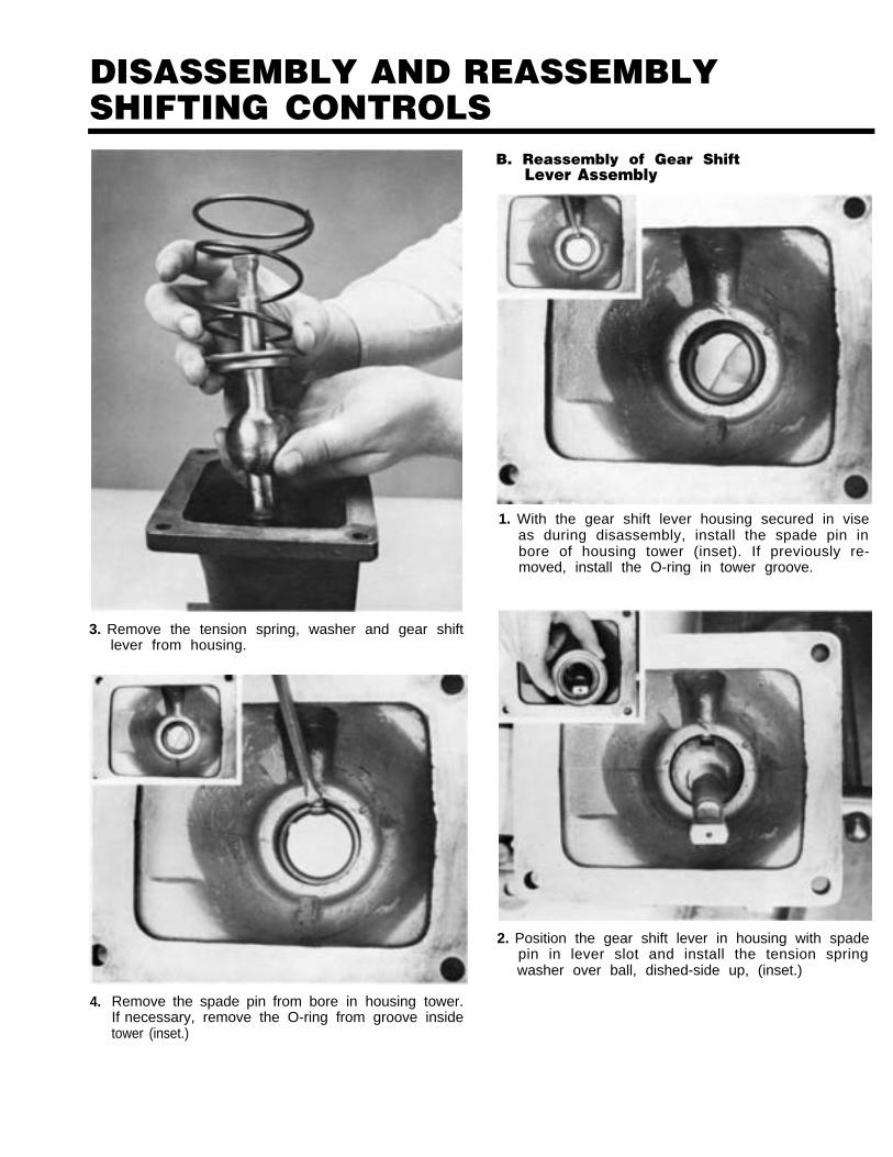
3. Remove the tension spring, washer and gear shiftlever from housing.
4. Remove the spade pin from bore in housing tower.
B. Reassembly of Gear ShiftLever Assembly
1. With the gear shift lever housing secured in viseas during disassembly, install the spade pin inbore of housing tower (inset). If previously re-moved, install the O-ring in tower groove.
2. Position the gear shift lever in housing with spadepin in lever slot and install the tension springwasher over ball, dished-side up, (inset.)
If necessary, remove the O-ring from groove insidetower (inset.)
DISASSEMBLY AND REASSEMBLYSHIFTING CONTROLS
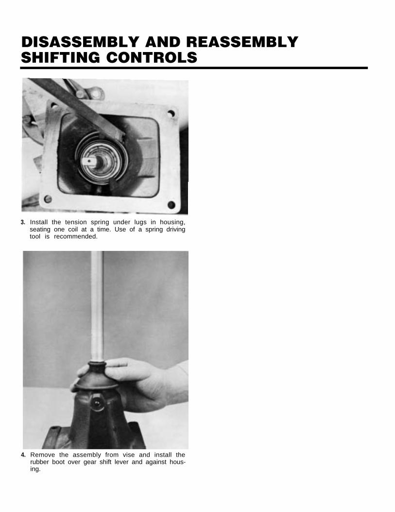
3.
4.
Install the tension spring under lugs in housing,seating one coil at a time. Use of a spring drivingtool is recommended.
Remove the assembly from vise and install therubber boot over gear shift lever and against hous-ing.
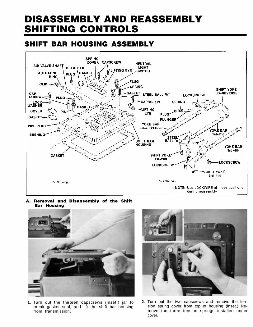
DISASSEMBLY AND REASSEMBLYSHIFTING CONTROLSSHIFT BAR HOUSING ASSEMBLY
A. Removal and Disassembly of the ShiftBar Housing
1. Turn out the thirteen capscrews (inset,) jar tobreak gasket seal, and lift the shift bar housingfrom transmission.
2. Turn out the two capscrews and remove the ten-sion spring cover from top of housing (inset.) Re-move the three tension springs installed undercover.
DISASSEMBLY AND REASSEMBLYSHIFTING CONTROLS
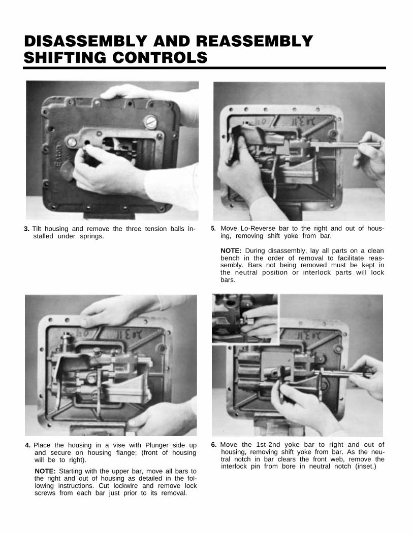
3. Tilt housing and remove the three tension balls in-stalled under springs.
4. Place the housing in a vise with Plunger side upand secure on housing flange; (front of housingwill be to right).
NOTE: Starting with the upper bar, move all bars tothe right and out of housing as detailed in the fol-lowing instructions. Cut lockwire and remove lockscrews from each bar just prior to its removal.
5. Move Lo-Reverse bar to the right and out of hous-ing, removing shift yoke from bar.
NOTE: During disassembly, lay all parts on a cleanbench in the order of removal to facilitate reas-sembly. Bars not being removed must be kept inthe neutral position or interlock parts will lockbars.
6. Move the 1st-2nd yoke bar to right and out ofhousing, removing shift yoke from bar. As the neu-tral notch in bar clears the front web, remove theinterlock pin from bore in neutral notch (inset.)
DISASSEMBLY AND REASSEMBLYSHIFTING CONTROLS
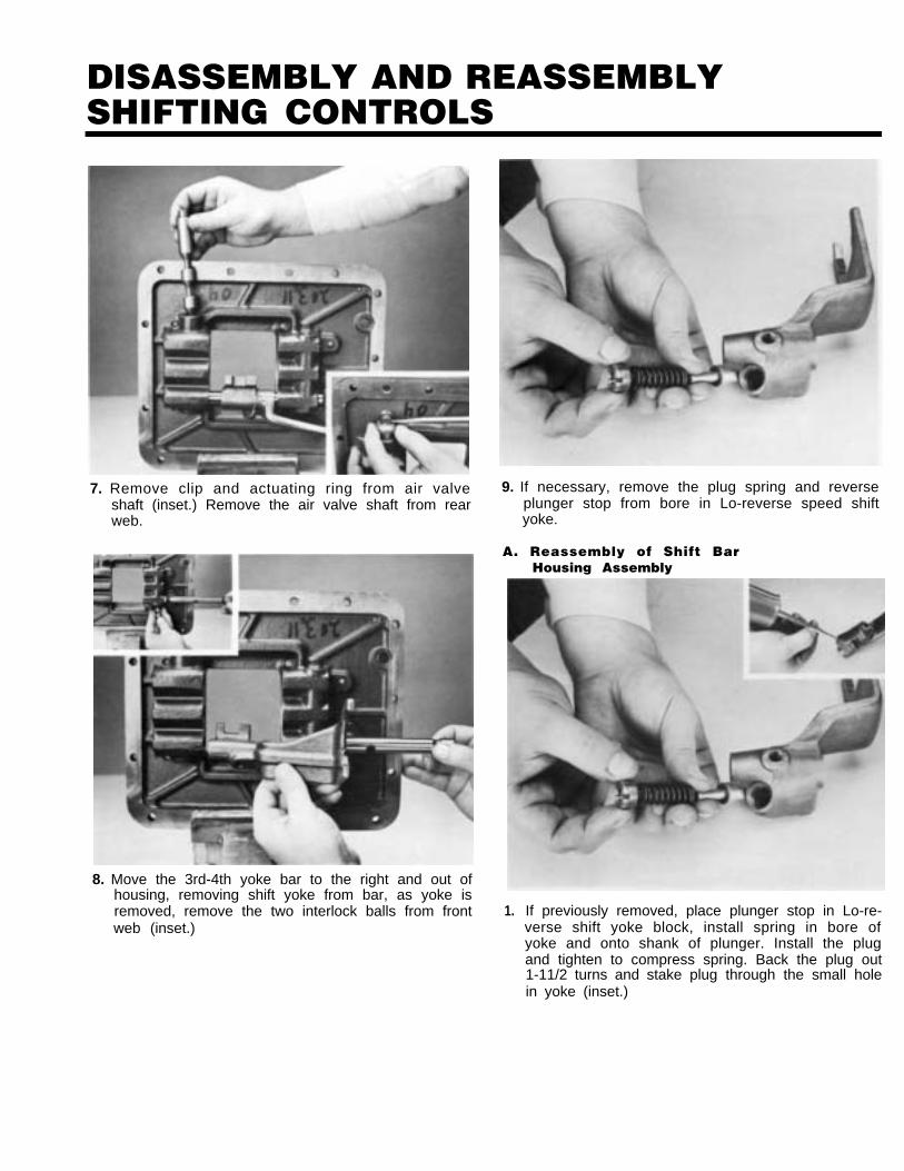
7. Remove clip and actuating ring from air valveshaft (inset.) Remove the air valve shaft from rearweb.
8. Move the 3rd-4th yoke bar to the right and out ofhousing, removing shift yoke from bar, as yoke isremoved, remove the two interlock balls from frontweb (inset.)
9. If necessary, remove the plug spring and reverseplunger stop from bore in Lo-reverse speed shiftyoke.
A. Reassembly of Shift BarHousing Assembly
1. If previously removed, place plunger stop in Lo-re-verse shift yoke block, install spring in bore ofyoke and onto shank of plunger. Install the plugand tighten to compress spring. Back the plug out1-11/2 turns and stake plug through the small holein yoke (inset.)
DISASSEMBLY AND REASSEMBLYSHIFTING CONTROLS
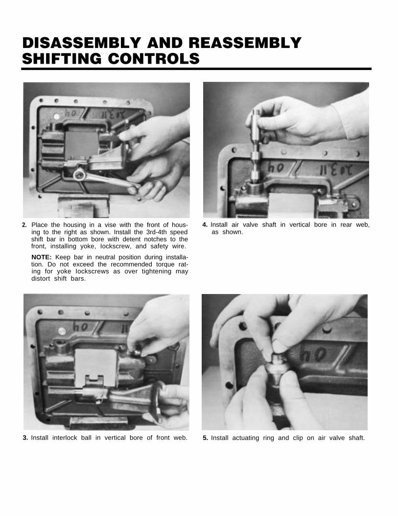
2. Place the housing in a vise with the front of hous-ing to the right as shown. Install the 3rd-4th speedshift bar in bottom bore with detent notches to thefront, installing yoke, Iockscrew, and safety wire.
NOTE: Keep bar in neutral position during installa-tion. Do not exceed the recommended torque rat-ing for yoke Iockscrews as over tightening maydistort shift bars.
4. Install air valve shaft in vertical bore in rear web,as shown.
3. Install interlock ball in vertical bore of front web. 5. Install actuating ring and clip on air valve shaft.
DISASSEMBLY AND REASSEMBLYSHIFTING CONTROLS
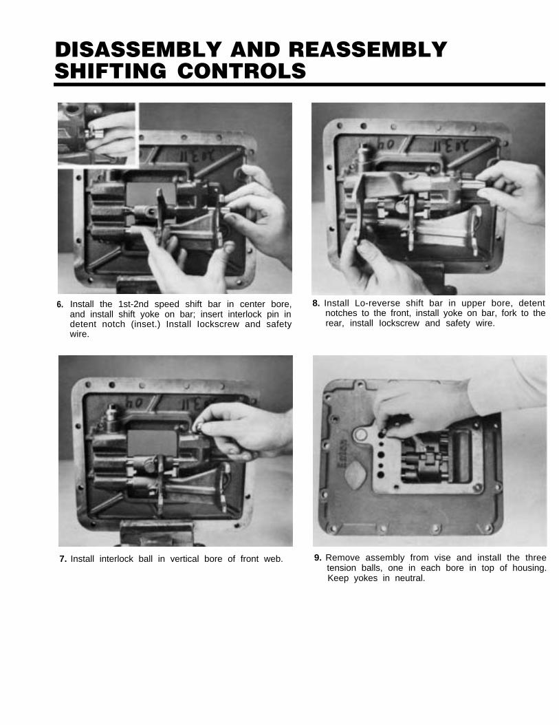
6. Install the 1st-2nd speed shift bar in center bore,and install shift yoke on bar; insert interlock pin indetent notch (inset.) Install Iockscrew and safetywire.
7. Install interlock ball in vertical bore of front web.
8. Install Lo-reverse shift bar in upper bore, detentnotches to the front, install yoke on bar, fork to therear, install Iockscrew and safety wire.
9. Remove assembly from vise and install the threetension balls, one in each bore in top of housing.Keep yokes in neutral.
DISASSEMBLY AND REASSEMBLYSHIFTING CONTROLS
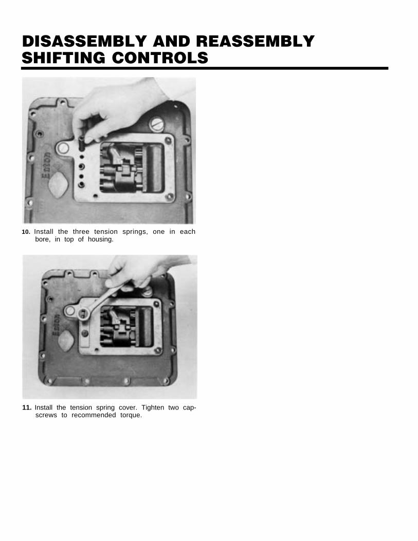
10. Install the three tension springs, one in eachbore, in top of housing.
11. Install the tension spring cover. Tighten two cap-screws to recommended torque.
REMOVAL-REAR YOKE, CLUTCH HOUSINGAND AUXILIARY SECTION
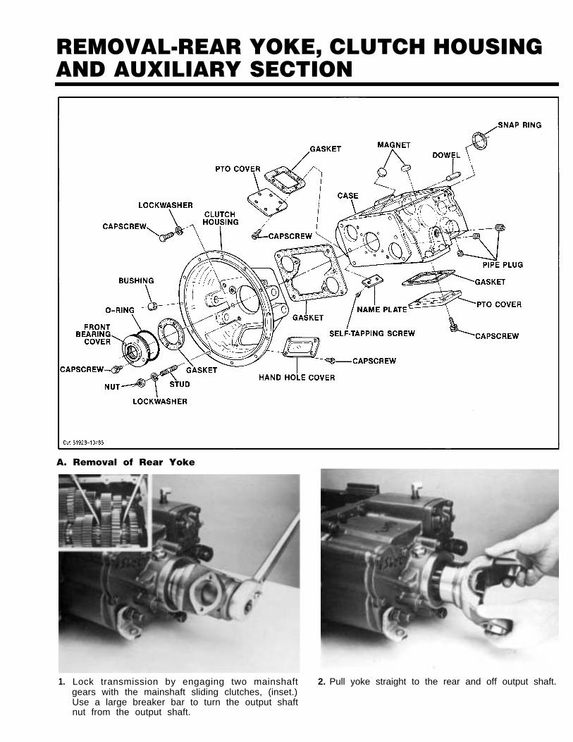
A. Removal of Rear Yoke
1. Lock transmission by engaging two mainshaft 2. Pull yoke straight to the rear and off output shaft.gears with the mainshaft sliding clutches, (inset.)Use a large breaker bar to turn the output shaftnut from the output shaft.
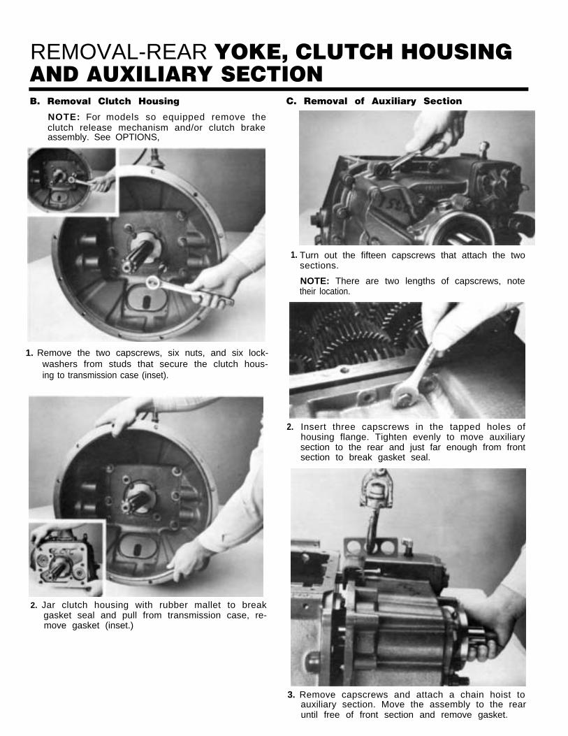
REMOVAL-REAR YOKE, CLUTCH HOUSINGAND AUXILIARY SECTIONB. Removal Clutch Housing
NOTE: For models so equipped remove theclutch release mechanism and/or clutch brakeassembly. See OPTIONS,
1. Remove the two capscrews, six nuts, and six lock-washers from studs that secure the clutch hous-ing to transmission case (inset).
2. Jar clutch housing with rubber mallet to breakgasket seal and pull from transmission case, re-move gasket (inset.)
C. Removal of Auxiliary Section
Turn out the fifteen capscrews that attach the twosections.
NOTE: There are two lengths of capscrews, notetheir location.
2. Insert three capscrews in the tapped holes ofhousing flange. Tighten evenly to move auxiliarysection to the rear and just far enough from frontsection to break gasket seal.
3. Remove capscrews and attach a chain hoist toauxiliary section. Move the assembly to the rearuntil free of front section and remove gasket.
1.
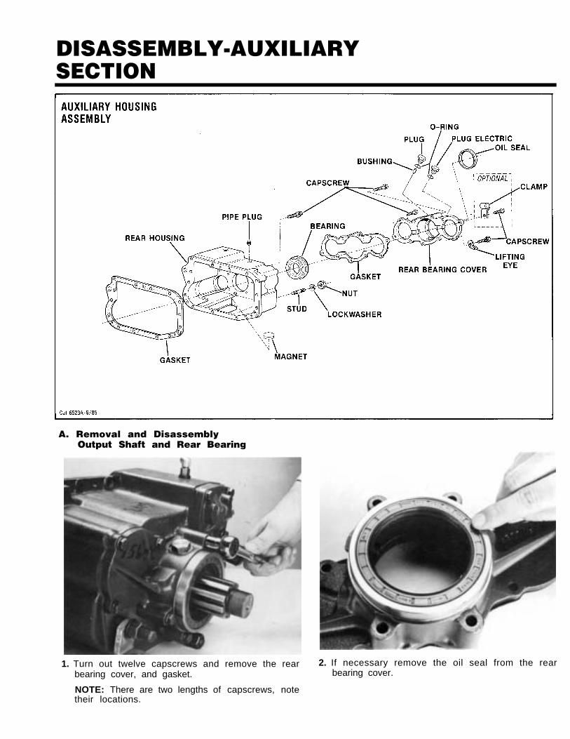
DISASSEMBLY-AUXILIARYSECTION
A. Removal and DisassemblyOutput Shaft and Rear Bearing
1. Turn out twelve capscrews and remove the rearbearing cover, and gasket.
2. If necessary remove the oil seal from the rearbearing cover.
NOTE: There are two lengths of capscrews, notetheir locations.
DISASSEMBLY-AUXILIARYSECTION
Cut 6549-9/85
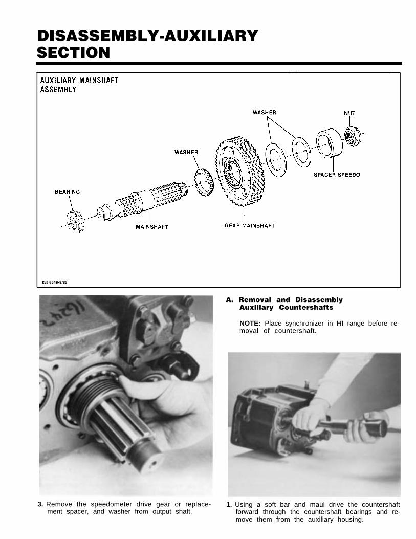
A. Removal and DisassemblyAuxiliary Countershafts
NOTE: Place synchronizer in HI range before re-moval of countershaft.
3. Remove the speedometer drive gear or replace- 1. Using a soft bar and maul drive the countershaftment spacer, and washer from output shaft. forward through the countershaft bearings and re-
move them from the auxiliary housing.
DISASSEMBLY-AUXILIARYSECTION
Cut 6482 A-1 2/83
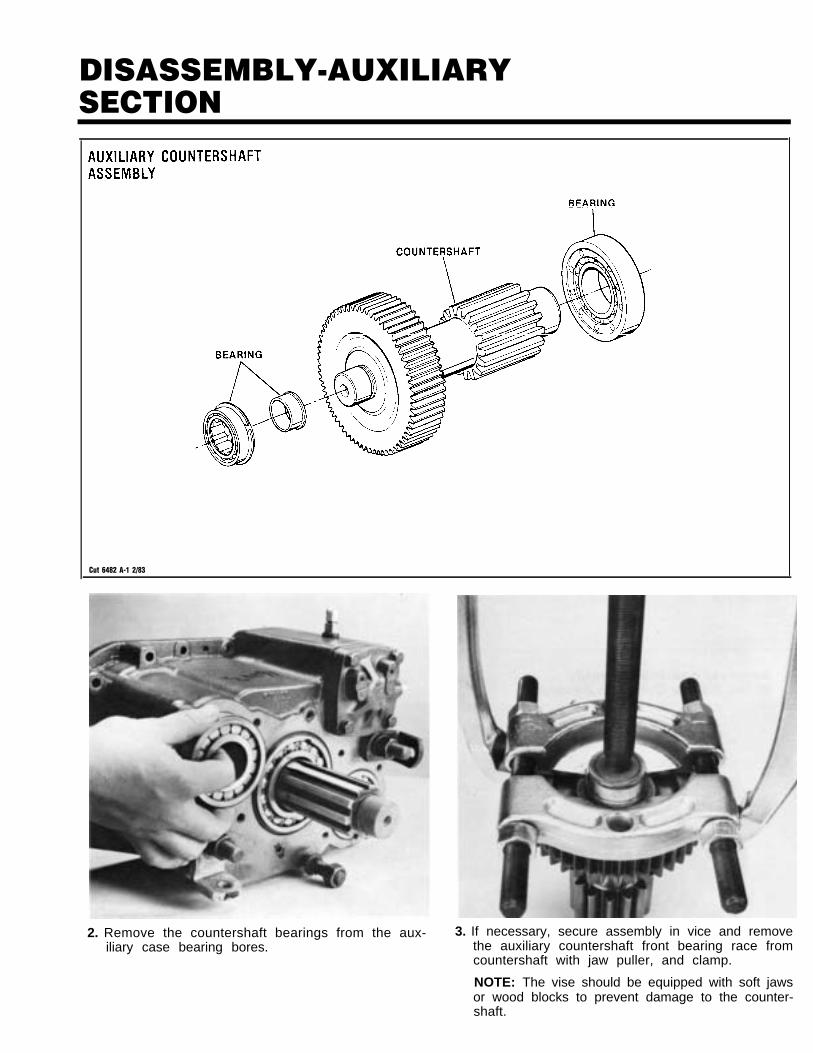
2. Remove the countershaft bearings from the aux- 3. If necessary, secure assembly in vice and removeiliary case bearing bores. the auxiliary countershaft front bearing race from
countershaft with jaw puller, and clamp.
NOTE: The vise should be equipped with soft jawsor wood blocks to prevent damage to the counter-shaft.
DISASSEMBLY-AUXILIARYSECTION
*NOTE: Use Lockwire
Cut 6422-2184at this position.
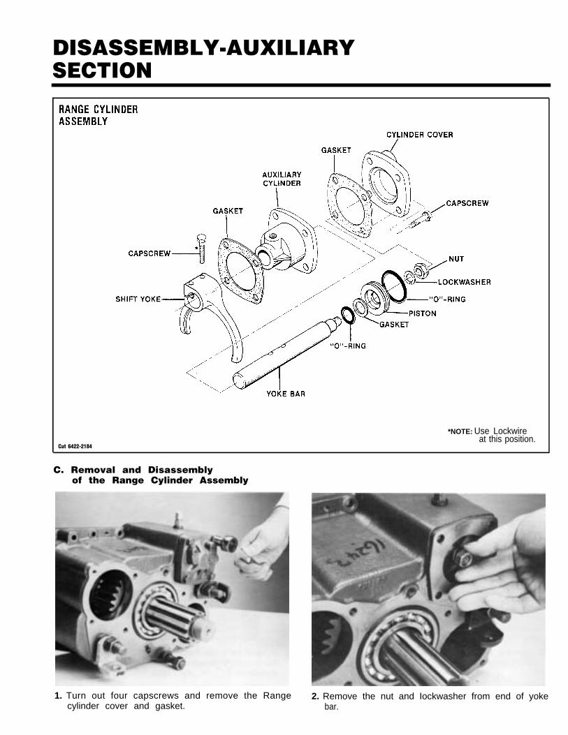
C. Removal and Disassemblyof the Range Cylinder Assembly
1. Turn out four capscrews and remove the Range 2. Remove the nut and Iockwasher from end of yokecylinder cover and gasket. bar.
DISASSEMBLY-AUXILIARYSECTION
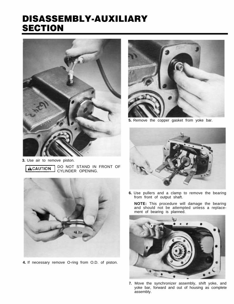
3. Use air to remove piston.
DO NOT STAND IN FRONT OFCYLINDER OPENING.
4. If necessary remove O-ring from O.D. of piston.
7.
5. Remove the copper gasket from yoke bar.
6. Use pullers and a clamp to remove the bearingfrom front of output shaft.
NOTE: This procedure will damage the bearingand should not be attempted unless a replace-ment of bearing is planned.
Move the synchronizer assembly, shift yoke, andyoke bar, forward and out of housing as completeassembly.
DISASSEMBLY-AUXILIARYSECTION
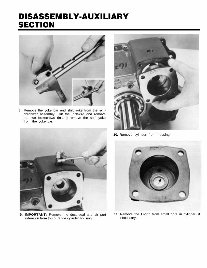
8. Remove the yoke bar and shift yoke from the syn-chronizer assembly. Cut the lockwire and removethe two Iockscrews (inset,) remove the shift yokefrom the yoke bar.
9. IMPORTANT: Remove the dust seal and air portextension from top of range cylinder housing.
10. Remove cylinder from housing.
11. Remove the O-ring from small bore in cylinder, ifnecessary.
DISASSEMBLY-AUXILIARYSECTION
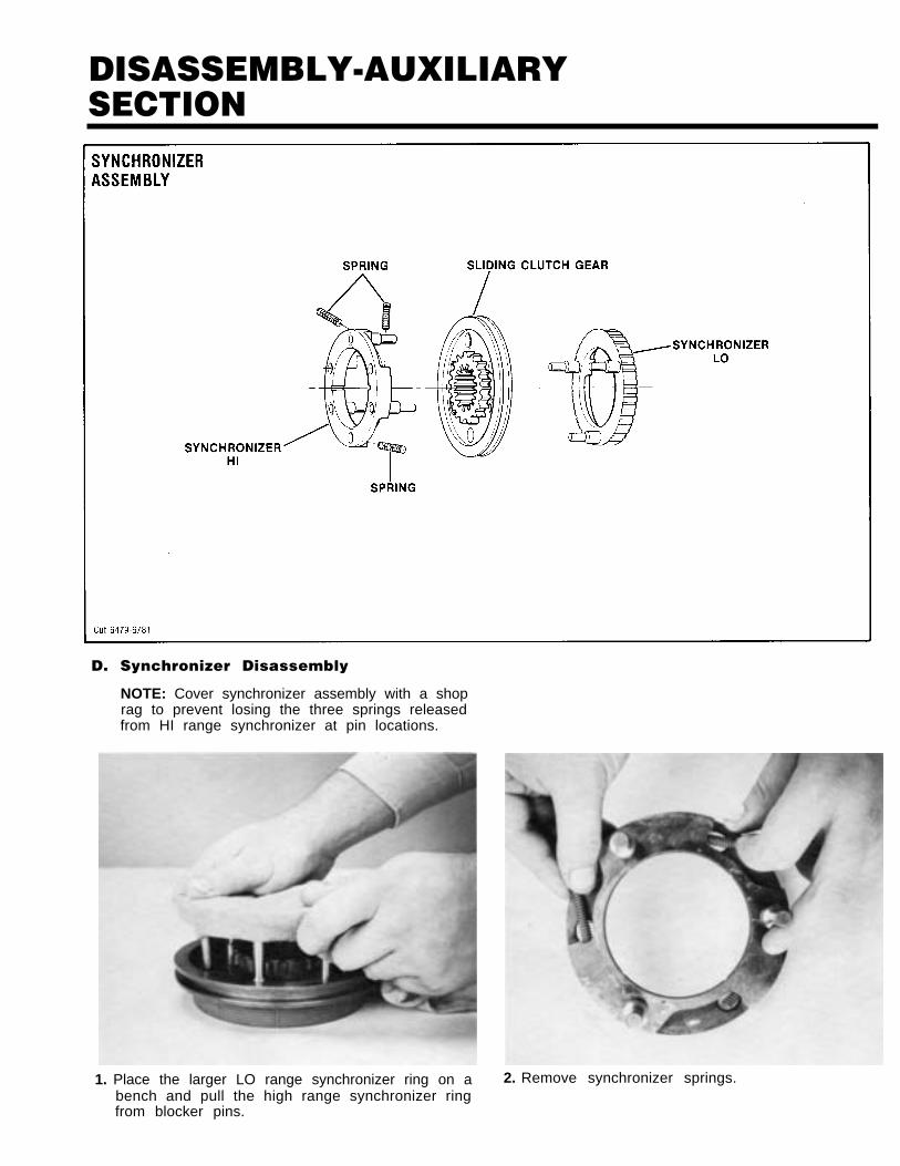
D. Synchronizer Disassembly
NOTE: Cover synchronizer assembly with a shoprag to prevent losing the three springs releasedfrom HI range synchronizer at pin locations.
1. Place the larger LO range synchronizer ring on a 2. Remove synchronizer springs.bench and pull the high range synchronizer ringfrom blocker pins.
47
DISASSEMBLY-AUXILIARYSECTION
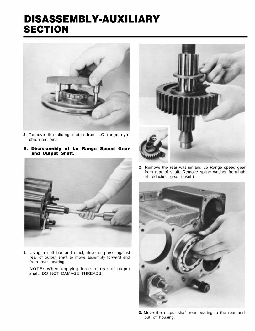
3. Remove the sliding clutch from LO range syn-chronizer pins.
E. Disassembly of Lo Range Speed Gearand Output Shaft.
1. Using a soft bar and maul, drive or press againstrear of output shaft to move assembly forward andfrom rear bearing.
NOTE: When applying force to rear of outputshaft, DO NOT DAMAGE THREADS.
2. Remove the rear washer and Lo Range speed gearfrom rear of shaft. Remove spline washer from-hubof reduction gear (inset.)
3. Move the output shaft rear bearing to the rear andout of housing.
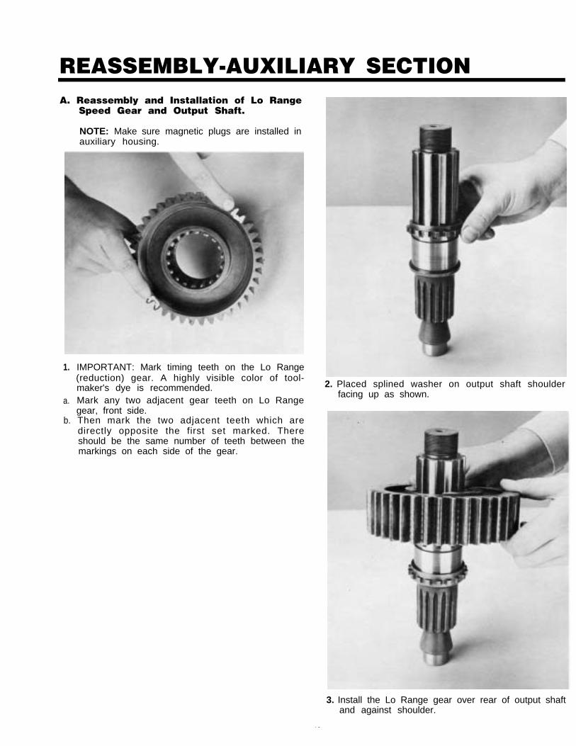
REASSEMBLY-AUXILIARY SECTIONA. Reassembly and Installation of Lo Range
Speed Gear and Output Shaft.
NOTE: Make sure magnetic plugs are installed inauxiliary housing.
1.
a.
b.
IMPORTANT: Mark timing teeth on the Lo Range(reduction) gear. A highly visible color of tool-maker's dye is recommended.Mark any two adjacent gear teeth on Lo Rangegear, front side.Then mark the two adjacent teeth which aredirectly opposite the first set marked. Thereshould be the same number of teeth between themarkings on each side of the gear.
2. Placed splined washer on output shaft shoulderfacing up as shown.
3. Install the Lo Range gear over rear of output shaftand against shoulder.
49
REASSEMBLY-AUXILIARY SECTION
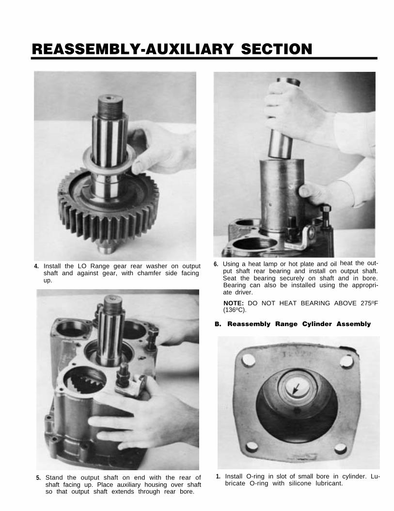
4.
5.
Install the LO Range gear rear washer on outputshaft and against gear, with chamfer side facingup.
Stand the output shaft on end with the rear ofshaft facing up. Place auxiliary housing over shaftso that output shaft extends through rear bore.
6.
B.
1.
Using a heat lamp or hot plate and oil heat the out-put shaft rear bearing and install on output shaft.Seat the bearing securely on shaft and in bore.Bearing can also be installed using the appropri-ate driver.
NOTE: DO NOT HEAT BEARING ABOVE 275oF(136oC).
Reassembly Range Cylinder Assembly
Install O-ring in slot of small bore in cylinder. Lu-bricate O-ring with silicone lubricant.
REASSEMBLY-AUXILIARY SECTION
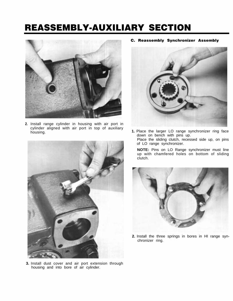
2. Install range cylinder in housing with air port incylinder aligned with air port in top of auxiliaryhousing.
.
C. Reassembly Synchronizer Assembly
1. Place the larger LO range synchronizer ring facedown on bench with pins up.Place the sliding clutch, recessed side up, on pinsof LO range synchronizer.
NOTE: Pins on LO Range synchronizer must lineup with chamfered holes on bottom of slidingclutch.
2. Install the three springs in bores in HI range syn-chronizer ring.
3. Install dust cover and air port extension throughhousing and into bore of air cylinder.
REASSEMBLY-AUXILIARY SECTION
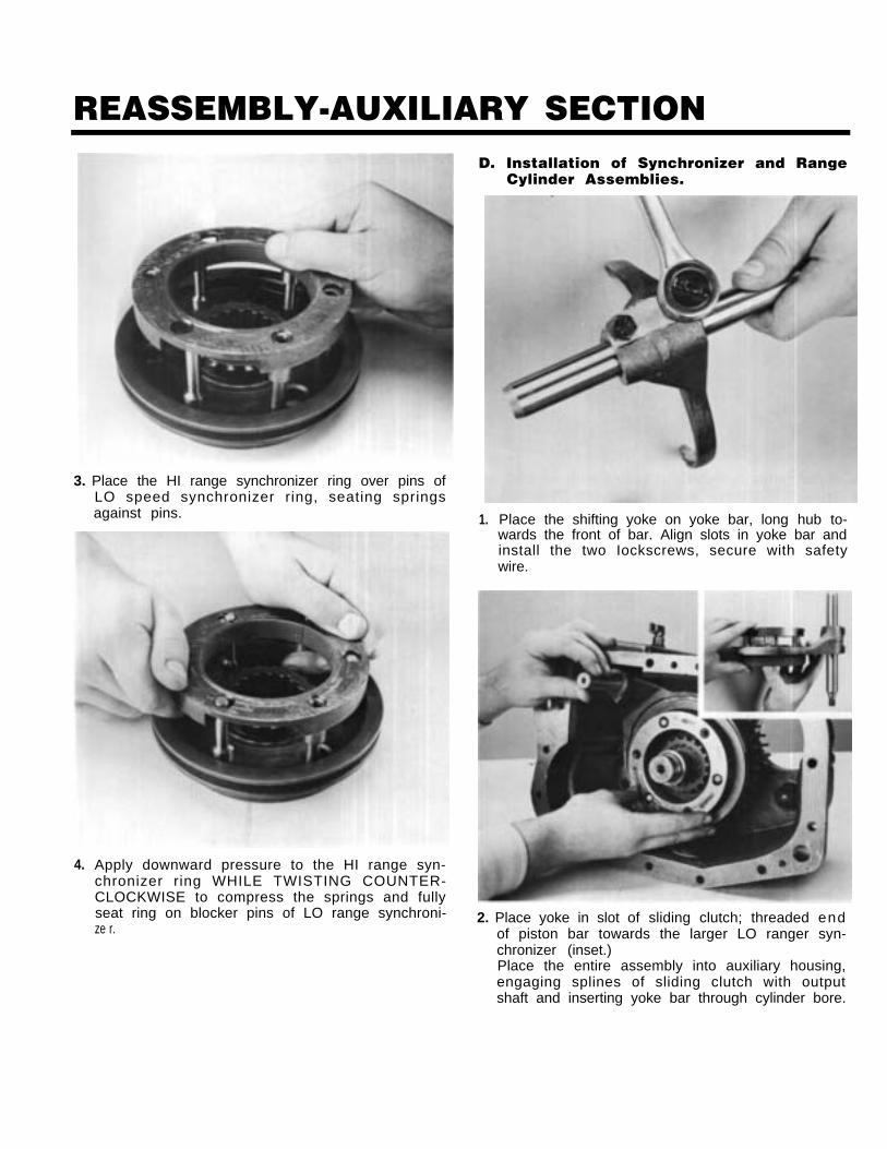
3. Place the HI range synchronizer ring over pins ofLO speed synchronizer ring, seating springsagainst pins.
4. Apply downward pressure to the HI range syn-chronizer ring WHILE TWISTING COUNTER-CLOCKWISE to compress the springs and fullyseat ring on blocker pins of LO range synchroni-ze r.
D. Installation of Synchronizer and Range
1. Place the shifting yoke on yoke bar, long hub to-wards the front of bar. Align slots in yoke bar andinstall the two Iockscrews, secure with safetywire.
Cylinder Assemblies.
2. Place yoke in slot of sliding clutch; threaded endof piston bar towards the larger LO ranger syn-chronizer (inset.)Place the entire assembly into auxiliary housing,engaging splines of sliding clutch with outputshaft and inserting yoke bar through cylinder bore.
REASSEMBLY-AUXILIARY SECTION
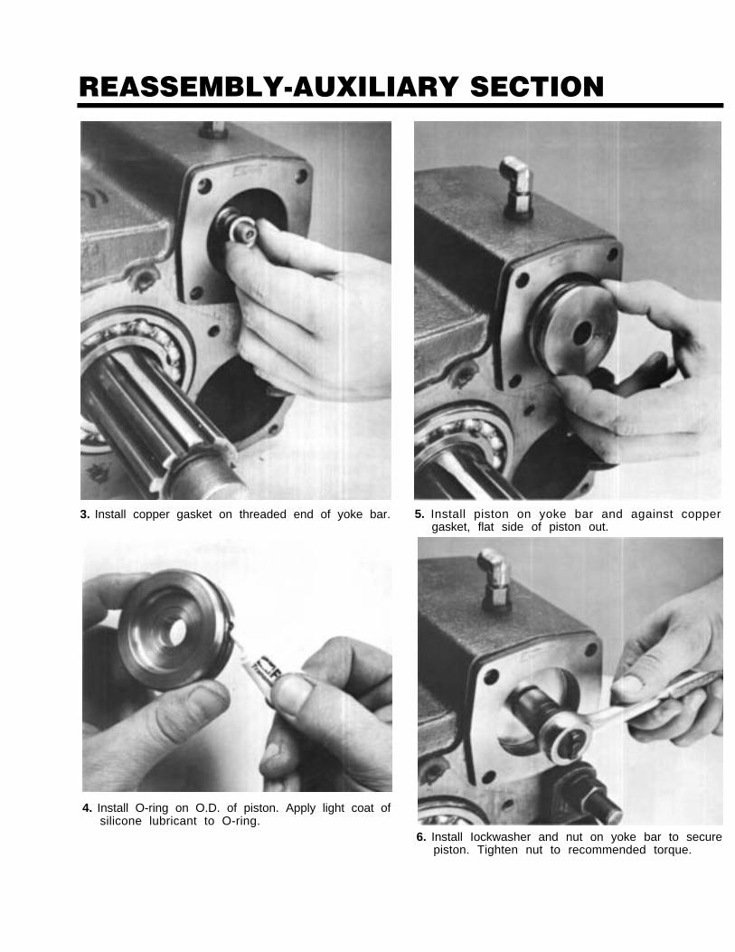
3. Install copper gasket on threaded end of yoke bar.
4. Install O-ring on O.D. of piston. Apply light coat ofsilicone lubricant to O-ring.
5. Install piston on yoke bar and against coppergasket, flat side of piston out.
6. Install Iockwasher and nut on yoke bar to securepiston. Tighten nut to recommended torque.
REASSEMBLY-AUXILIARY SECTION
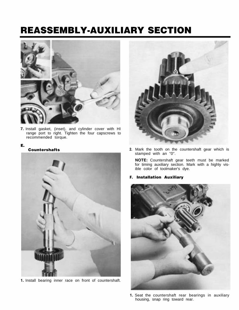
7. Install gasket, (inset), and cylinder cover with HIrange port to right. Tighten the four capscrews torecommended torque.
E.Countershafts
1. Install bearing inner race on front of countershaft.
2.
F.
Mark the tooth on the countershaft gear which isstamped with an "0".
NOTE: Countershaft gear teeth must be markedfor timing auxiliary section. Mark with a highly vis-ible color of toolmaker's dye.
Installation Auxiliary
1. Seat the countershaft rear bearings in auxiliaryhousing, snap ring toward rear.
REASSEMBLY-AUXILIARY SECTION
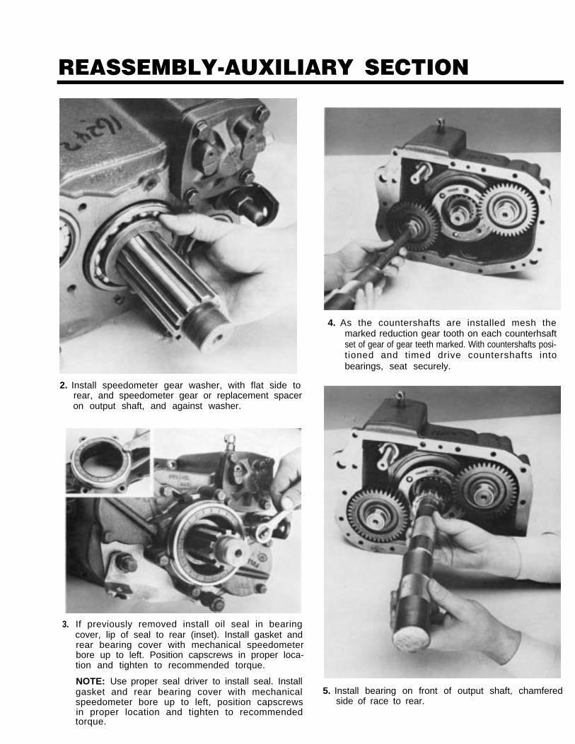
4. As the countershafts are installed mesh themarked reduction gear tooth on each counterhsaftset of gear of gear teeth marked. With countershafts posi-tioned and timed drive countershafts intobearings, seat securely.
2. Install speedometer gear washer, with flat side torear, and speedometer gear or replacement spaceron output shaft, and against washer.
3. If previously removed install oil seal in bearingcover, lip of seal to rear (inset). Install gasket andrear bearing cover with mechanical speedometerbore up to left. Position capscrews in proper loca-tion and tighten to recommended torque.
NOTE: Use proper seal driver to install seal. Installgasket and rear bearing cover with mechanicalspeedometer bore up to left, position capscrewsin proper location and tighten to recommendedtorque.
5. Install bearing on front of output shaft, chamferedside of race to rear.
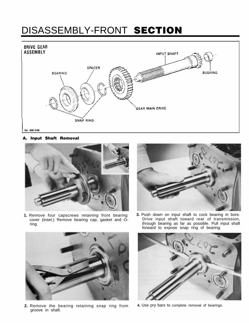
DISASSEMBLY-FRONT SECTION
Cut 6387-2180
A. Input Shaft Removal
1. Remove four capscrews retaining front bearingcover (inset.) Remove bearing cap, gasket and O-ring.
2. Remove the bearing retaining snap ring fromgroove in shaft.
3. Push down on input shaft to cock bearing in bore.Drive input shaft toward rear of transmission,through bearing as far as possible. Pull input shaftforward to expose snap ring of bearing.
4. Use pry bars to complete removal of bearings.
DISASSEMBLY-FRONT SECTION
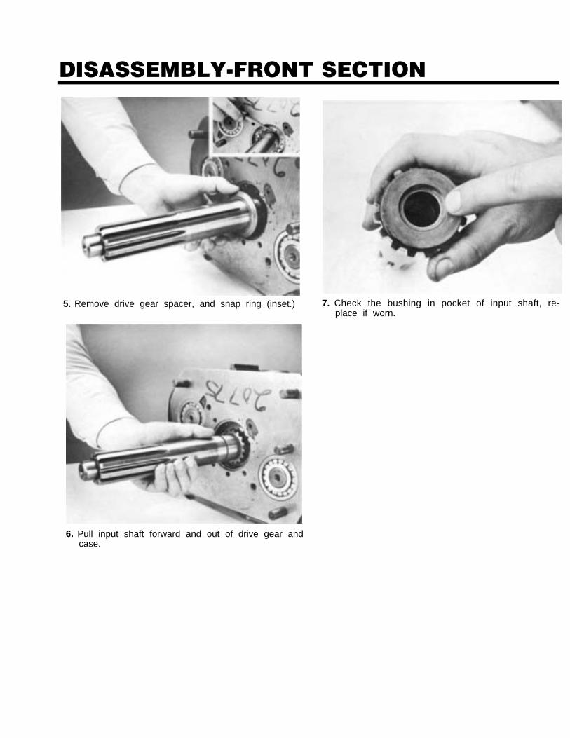
5. Remove drive gear spacer, and snap ring (inset.) 7. Check the bushing in pocket of input shaft, re-place if worn.
6. Pull input shaft forward and out of drive gear andcase.
DISASSEMBLY-FRONT SECTION
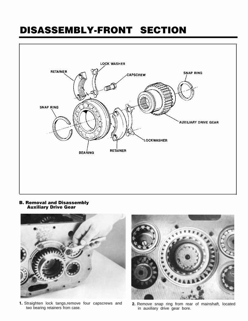
B. Removal and DisassemblyAuxiliary Drive Gear
1. Straighten lock tangs,remove four capscrews andtwo bearing retainers from case.
2. Remove snap ring from rear of mainshaft, locatedin auxiliary drive gear bore.
DISASSEMBLY-FRONT SECTION
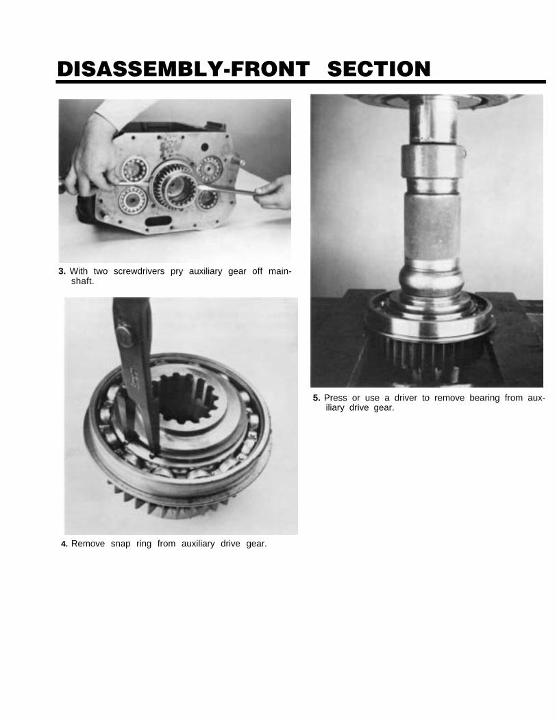
3. With two screwdrivers pry auxiliary gear off main-shaft.
5. Press or use a driver to remove bearing from aux-iliary drive gear.
4. Remove snap ring from auxiliary drive gear.
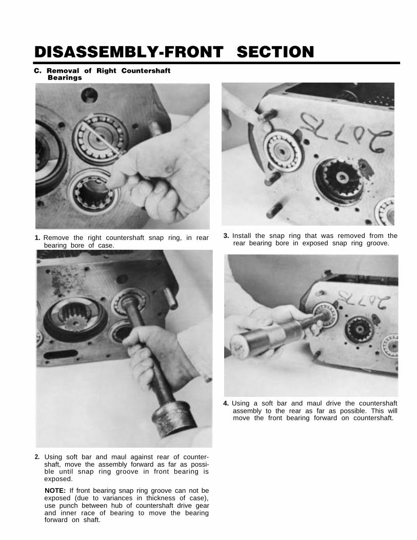
DISASSEMBLY-FRONT SECTIONC. Removal of Right Countershaft
Bearings
1. Remove the right countershaft snap ring, in rearbearing bore of case.
2. Using soft bar and maul against rear of counter-shaft, move the assembly forward as far as possi-ble until snap ring groove in front bearing isexposed.
NOTE: If front bearing snap ring groove can not beexposed (due to variances in thickness of case),use punch between hub of countershaft drive gearand inner race of bearing to move the bearingforward on shaft.
3. Install the snap ring that was removed from therear bearing bore in exposed snap ring groove.
4. Using a soft bar and maul drive the countershaftassembly to the rear as far as possible. This willmove the front bearing forward on countershaft.
DISASSEMBLY-FRONT SECTION
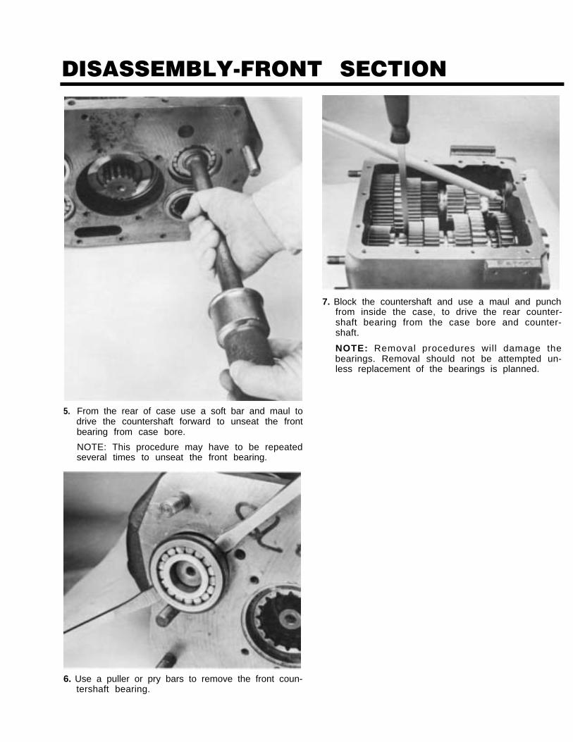
5. From the rear of case use a soft bar and maul todrive the countershaft forward to unseat the frontbearing from case bore.
NOTE: This procedure may have to be repeatedseveral times to unseat the front bearing.
7. Block the countershaft and use a maul and punchfrom inside the case, to drive the rear counter-shaft bearing from the case bore and counter-shaft.
NOTE: Removal procedures will damage thebearings. Removal should not be attempted un-less replacement of the bearings is planned.
6. Use a puller or pry bars to remove the front coun-tershaft bearing.
DISASSEMBLY-FRONT SECTION
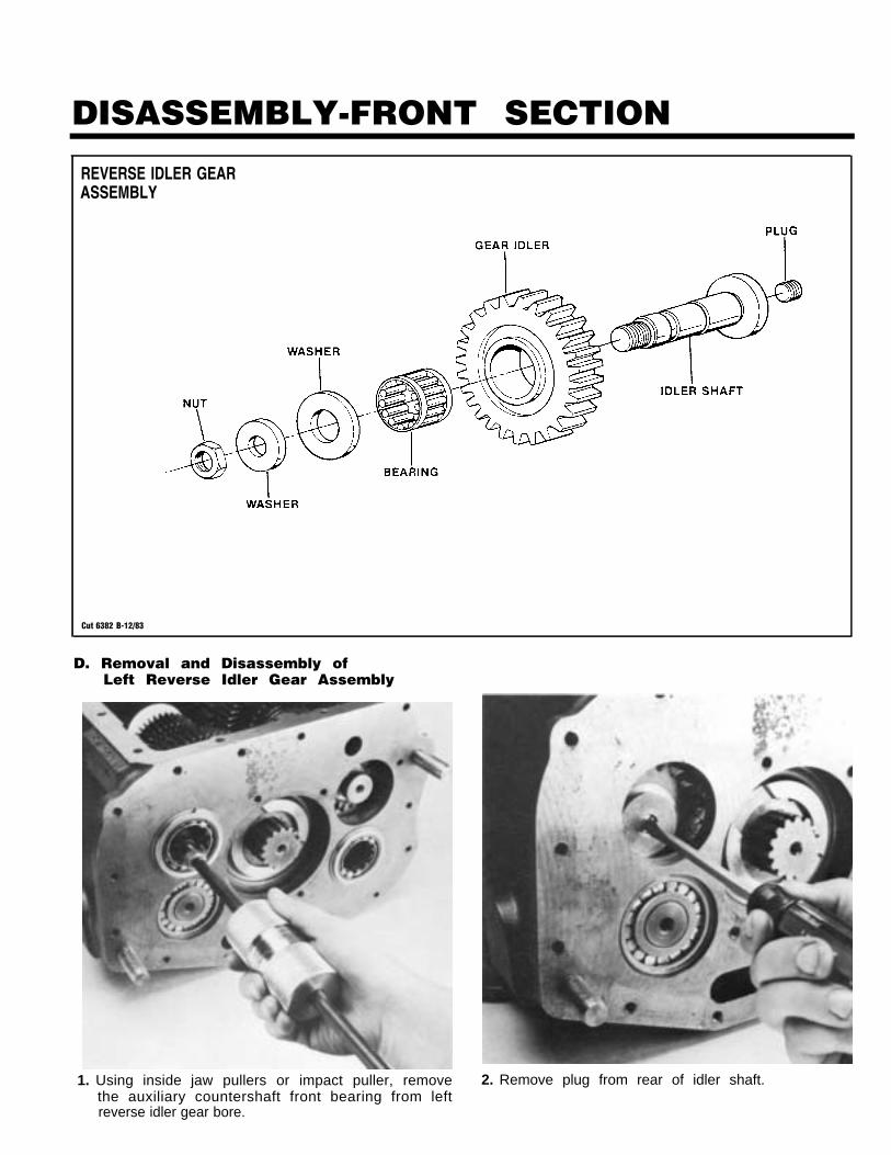
REVERSE IDLER GEARASSEMBLY
Cut 6382 B-12/83
D. Removal and Disassembly ofLeft Reverse Idler Gear Assembly
1. Using inside jaw pullers or impact puller, removethe auxiliary countershaft front bearing from leftreverse idler gear bore.
2. Remove plug from rear of idler shaft.
DISASSEMBLY-FRONT SECTION
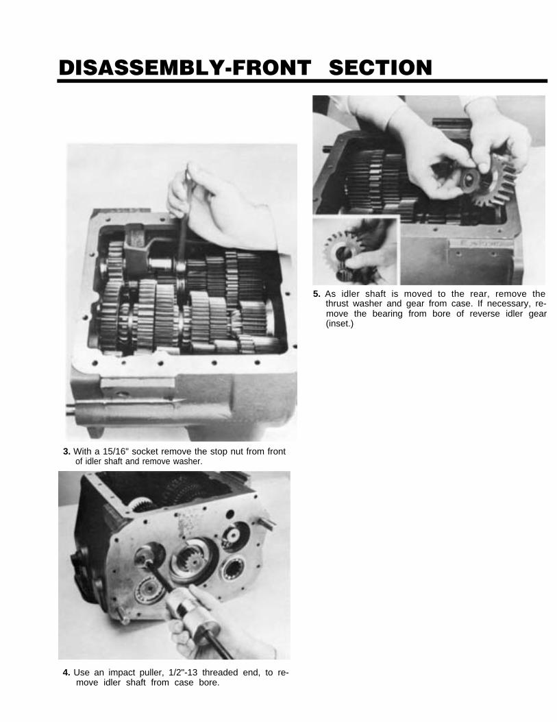
3. With a 15/16" socket remove the stop nut from frontof idler shaft and remove washer.
4. Use an impact puller, 1/2"-13 threaded end, to re-move idler shaft from case bore.
5. As idler shaft is moved to the rear, remove thethrust washer and gear from case. If necessary, re-move the bearing from bore of reverse idler gear(inset.)
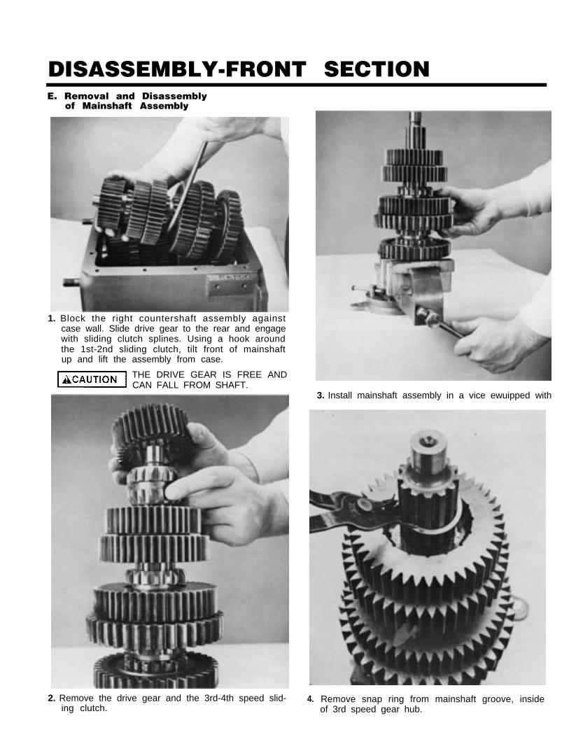
DISASSEMBLY-FRONT SECTIONE. Removal and Disassembly
of Mainshaft Assembly
1. Block the right countershaft assembly againstcase wall. Slide drive gear to the rear and engagewith sliding clutch splines. Using a hook aroundthe 1st-2nd sliding clutch, tilt front of mainshaftup and lift the assembly from case.
THE DRIVE GEAR IS FREE ANDCAN FALL FROM SHAFT.
3. Install mainshaft assembly in a vice ewuipped with
2. Remove the drive gear and the 3rd-4th speed slid-ing clutch.
4. Remove snap ring from mainshaft groove, insideof 3rd speed gear hub.
DISASSEMBLY-FRONT SECTION
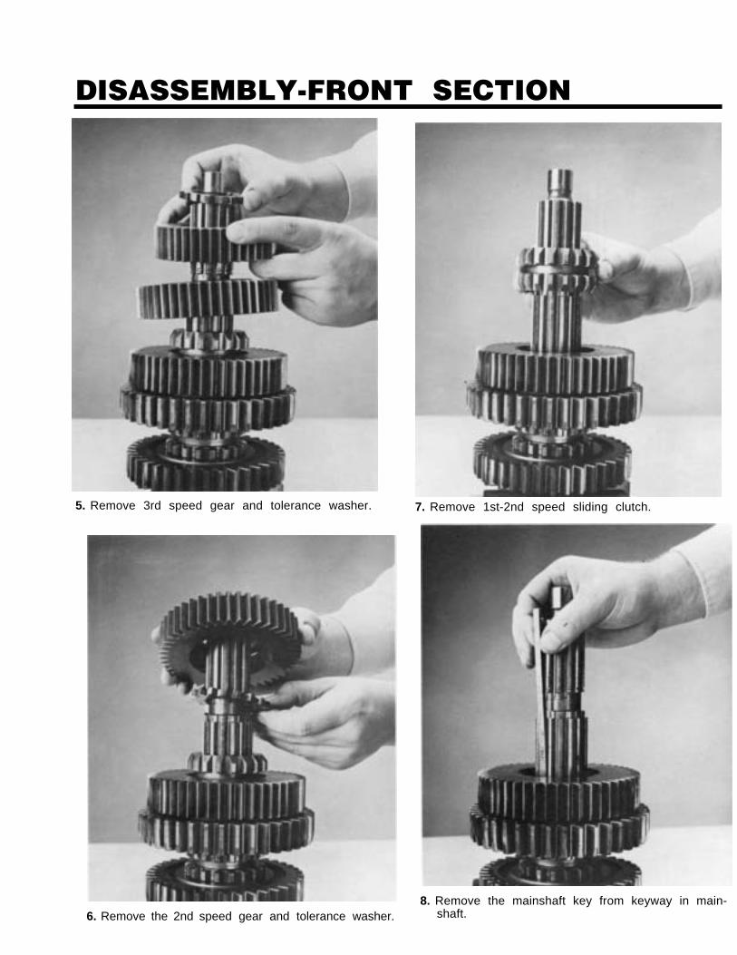
6. Remove the 2nd speed gear and tolerance washer.
7. Remove 1st-2nd speed sliding clutch.
8. Remove the mainshaft key from keyway in main-shaft.
5. Remove 3rd speed gear and tolerance washer.

DISASSEMBLY-FRONT SECTION
9. Remove 1st speed gear and tolerance washer.
10. Remove Lo speed gear and tolerance washer.
11. Remove Lo and reverse speed sliding clutch.
12. Remove the reverse gear and tolerance washer.
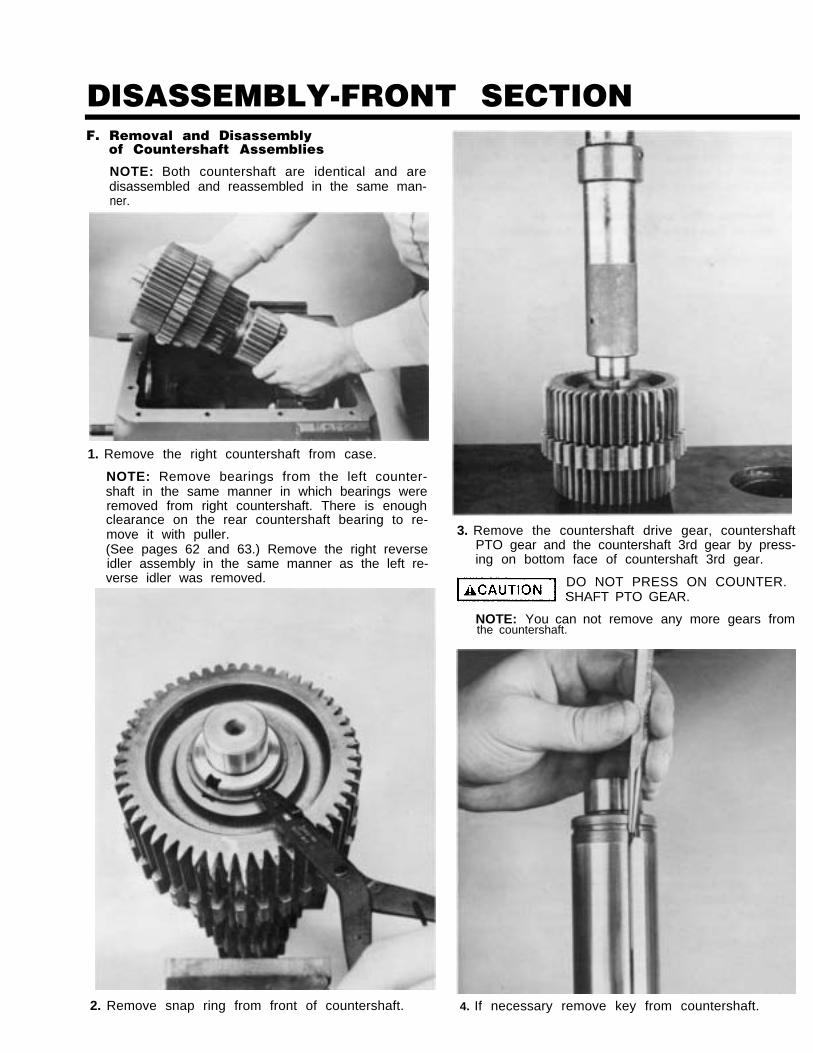
DISASSEMBLY-FRONT SECTIONF. Removal and Disassembly
of Countershaft Assemblies
NOTE: Both countershaft are identical and aredisassembled and reassembled in the same man-ner.
1. Remove the right countershaft from case.
NOTE: Remove bearings from the left counter-shaft in the same manner in which bearings wereremoved from right countershaft. There is enoughclearance on the rear countershaft bearing to re-move it with puller.(See pages 62 and 63.) Remove the right reverseidler assembly in the same manner as the left re-verse idler was removed.
the countershaft.
2. Remove snap ring from front of countershaft.
3. Remove the countershaft drive gear, countershaftPTO gear and the countershaft 3rd gear by press-ing on bottom face of countershaft 3rd gear.
DO NOT PRESS ON COUNTER.SHAFT PTO GEAR.
NOTE: You can not remove any more gears from
4. If necessary remove key from countershaft.
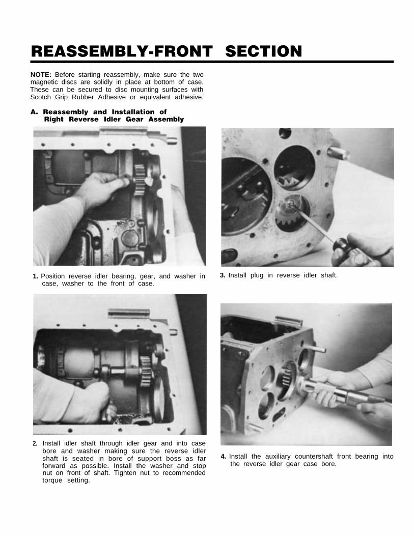
REASSEMBLY-FRONT SECTIONNOTE: Before starting reassembly, make sure the twomagnetic discs are solidly in place at bottom of case.These can be secured to disc mounting surfaces withScotch Grip Rubber Adhesive or equivalent adhesive.
A. Reassembly and Installation ofRight Reverse Idler Gear Assembly
2. Install idler shaft through idler gear and into casebore and washer making sure the reverse idlershaft is seated in bore of support boss as farforward as possible. Install the washer and stopnut on front of shaft. Tighten nut to recommendedtorque setting.
1. Position reverse idler bearing, gear, and washer incase, washer to the front of case.
3. Install plug in reverse idler shaft.
4. Install the auxiliary countershaft front bearing intothe reverse idler gear case bore.
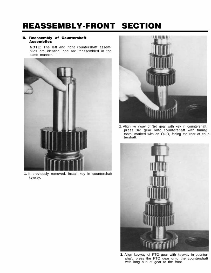
REASSEMBLY-FRONT SECTIONB. Reassembly of Countershaft
Assemblies
NOTE: The left and right countershaft assem-blies are identical and are reassembled in thesame manner.
1. If previously removed, install key in countershaftkeyway.
2. Align ke yway of 3rd gear with key in countershaft,press 3rd gear onto countershaft with timingtooth, marked with an ÒOÓ, facing the rear of coun-tershaft.
3. Align keyway of PTO gear with keyway in counter-shaft, press the PTO gear onto the countershaftwith long hub of gear to the front.
REASSEMBLY-FRONT SECTION
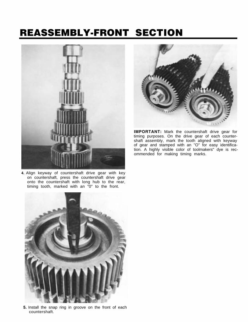
4. Align keyway of countershaft drive gear with keyon countershaft, press the countershaft drive gearonto the countershaft with long hub to the rear,timing tooth, marked with an "0" to the front.
IMPORTANT: Mark the countershaft drive gear fortiming purposes. On the drive gear of each counter-shaft assembly, mark the tooth aligned with keywayof gear and stamped with an "O" for easy identifica-tion. A highly visible color of toolmakers" dye is rec-ommended for making timing marks.
5. Install the snap ring in groove on the front of eachcountershaft.
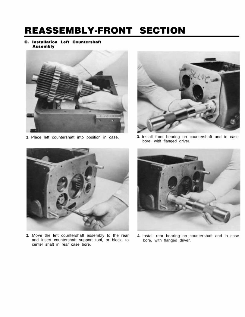
REASSEMBLY-FRONT SECTIONC. Installation Left Countershaft
Assembly
1. Place left countershaft into position in case.
2. Move the left countershaft assembly to the rearand insert countershaft support tool, or block, tocenter shaft in rear case bore.
3. Install front bearing on countershaft and in casebore, with flanged driver.
4. Install rear bearing on countershaft and in casebore, with flanged driver.
REASSEMBLY-FRONT SECTION
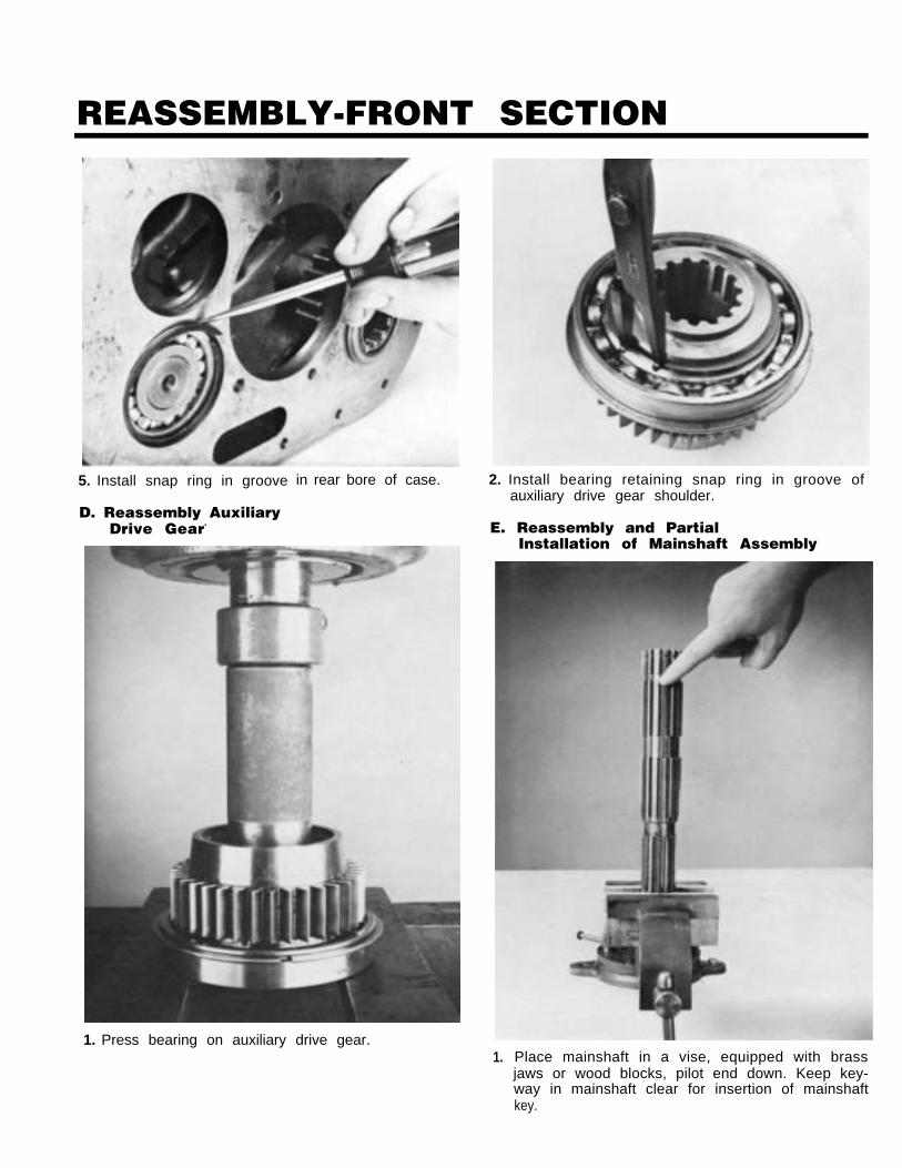
5. Install snap ring in groove in rear bore of case.
D. Reassembly AuxiliaryDrive Gear-
1. Press bearing on auxiliary drive gear.
2. Install bearing retaining snap ring in groove ofauxiliary drive gear shoulder.
E. Reassembly and PartialInstallation of Mainshaft Assembly
1. Place mainshaft in a vise, equipped with brassjaws or wood blocks, pilot end down. Keep key-way in mainshaft clear for insertion of mainshaftkey.
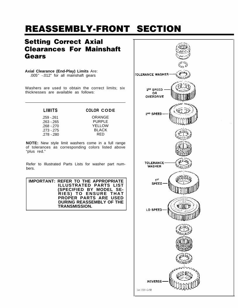
REASSEMBLY-FRONT SECTIONSetting Correct AxialClearances For MainshaftGears
Axial Clearance (End-Play) Limits Are:.005’’ -.012” for all mainshaft gears
Washers are used to obtain the correct limits; sixthicknesses are available as follows:
LIMITS COLOR CODE
.259 -.261 ORANGE
.263 -.265 PURPLE
.268 -.270 YELLOW
.273 -.275 BLACK
.278 -.280 RED
NOTE: New style limit washers come in a full rangeof tolerances as corresponding colors listed above“plus red.”
Refer to Illustrated Parts Lists for washer part num-bers.
IMPORTANT: REFER TO THE APPROPRIATEILLUSTRATED PARTS LIST(SPECIFIED BY MODEL SE-R I E S ) T O E N S U R E T H A TPROPER PARTS ARE USEDDURING REASSEMBLY OF THETRANSMISSION.
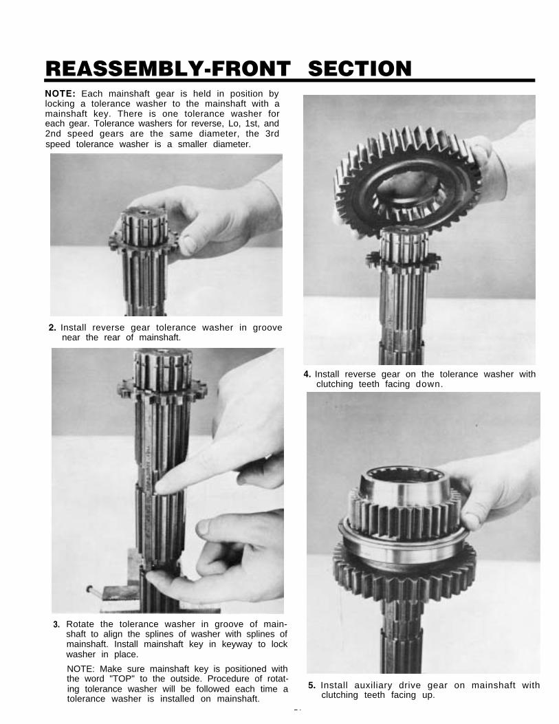
REASSEMBLY-FRONT SECTIONNOTE: Each mainshaft gear is held in position bylocking a tolerance washer to the mainshaft with amainshaft key. There is one tolerance washer foreach gear. Tolerance washers for reverse, Lo, 1st, and2nd speed gears are the same diameter, the 3rdspeed tolerance washer is a smaller diameter.
2. Install reverse gear tolerance washer in groovenear the rear of mainshaft.
4. Install reverse gear on the tolerance washer withclutching teeth facing down.
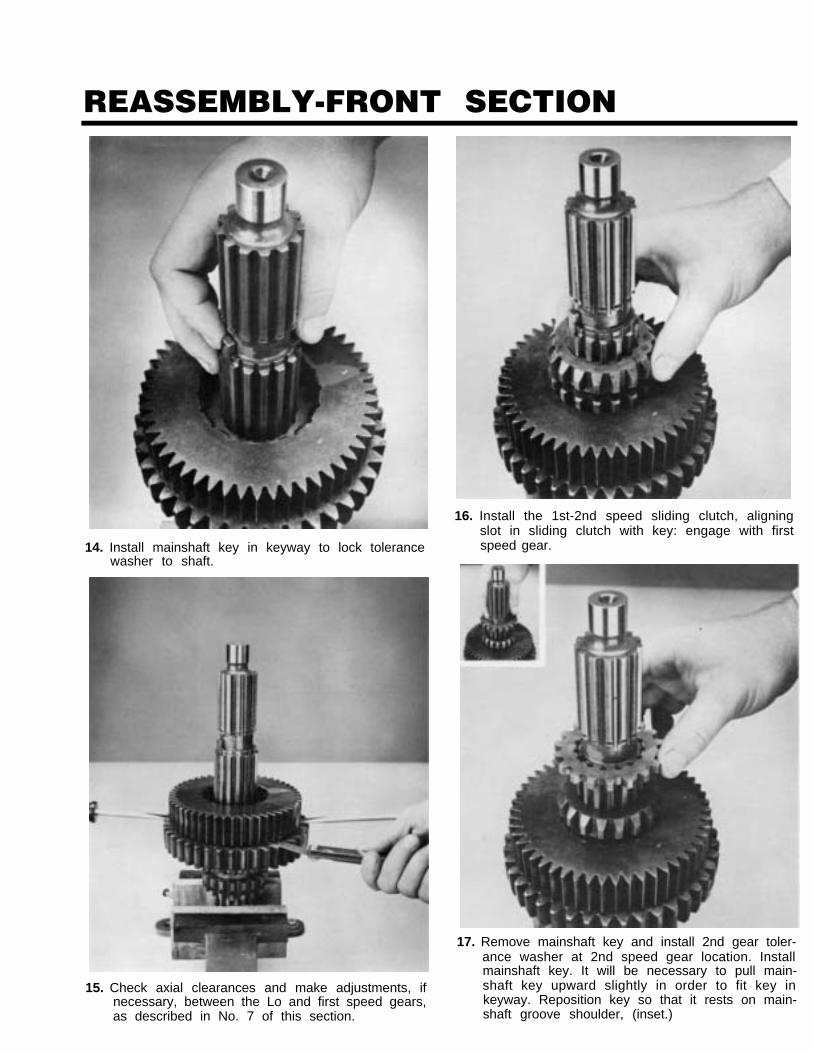
3. Rotate the tolerance washer in groove of main-shaft to align the splines of washer with splines ofmainshaft. Install mainshaft key in keyway to lockwasher in place.
NOTE: Make sure mainshaft key is positioned withthe word "TOP" to the outside. Procedure of rotat-ing tolerance washer will be followed each time atolerance washer is installed on mainshaft.
5. Install auxiliary drive gear on mainshaft withclutching teeth facing up.
74
REASSEMBLY-FRONT SECTION
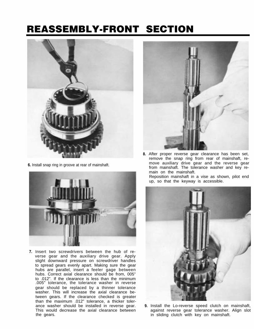
6. Install snap ring in groove at rear of mainshaft.
7. Insert two screwdrivers between the hub of re-verse gear and the auxiliary drive gear. Applyslight downward pressure on screwdriver handlesto spread gears evenly apart. Making sure the gearhubs are parallel, insert a feeler gage betweenhubs. Correct axial clearance should be from, 005"to .012". If the clearance is less than the minimum.005" tolerance, the tolerance washer in reversegear should be replaced by a thinner tolerancewasher. This will increase the axial clearance be-tween gears. If the clearance checked is greaterthan the maximum .012" tolerance, a thicker toler-ance washer should be installed in reverse gear.This would decrease the axial clearance betweenthe gears.
8.
9.
After proper reverse gear clearance has been set,remove the snap ring from rear of mainshaft, re-move auxiliary drive gear and the reverse gearfrom mainshaft. The tolerance washer and key re-main on the mainshaft.Reposition mainshaft in a vise as shown, pilot endup, so that the keyway is accessible.
Install the Lo-reverse speed clutch on mainshaft,against reverse gear tolerance washer. Align slotin sliding clutch with key on mainshaft.
REASSEMBLY-FRONT SECTION
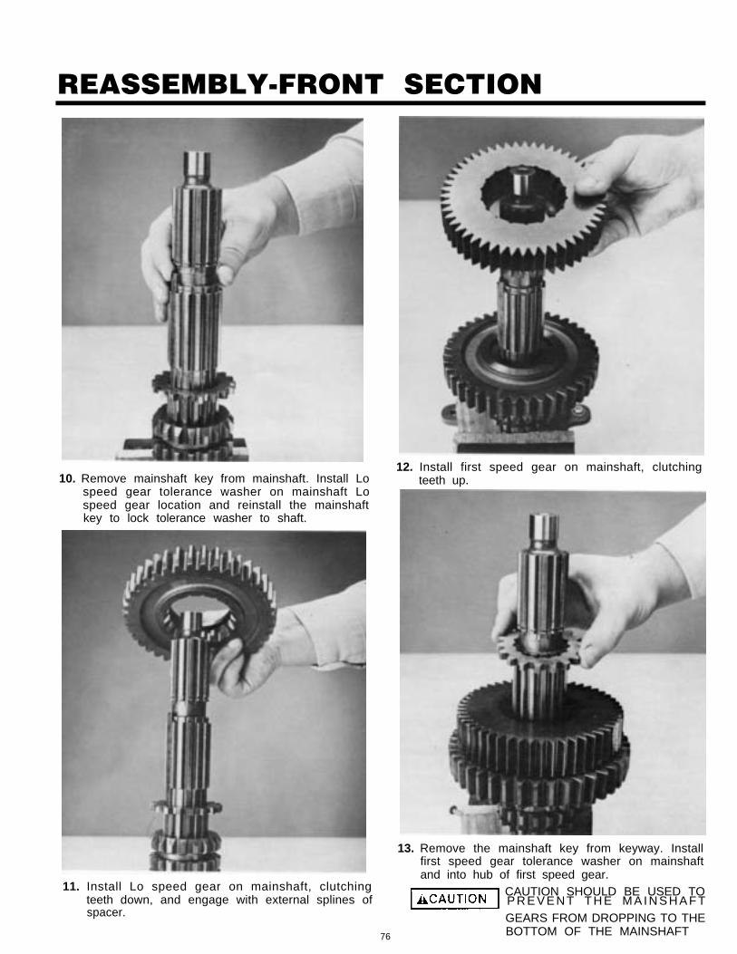
10. Remove mainshaft key from mainshaft. Install Lospeed gear tolerance washer on mainshaft Lospeed gear location and reinstall the mainshaftkey to lock tolerance washer to shaft.
11. Install Lo speed gear on mainshaft, clutchingteeth down, and engage with external splines ofspacer.
12. Install first speed gear on mainshaft, clutchingteeth up.
13. Remove the mainshaft key from keyway. Installfirst speed gear tolerance washer on mainshaftand into hub of first speed gear.
CAUTION SHOULD BE USED TOP R E V E N T T H E M A I N S H A F TGEARS FROM DROPPING TO THE
76 BOTTOM OF THE MAINSHAFT
REASSEMBLY-FRONT SECTION
14. Install mainshaft key in keyway to lock tolerancewasher to shaft.
15. Check axial clearances and make adjustments, ifnecessary, between the Lo and first speed gears,as described in No. 7 of this section.
16. Install the 1st-2nd speed sliding clutch, aligningslot in sliding clutch with key: engage with firstspeed gear.
17. Remove mainshaft key and install 2nd gear toler-ance washer at 2nd speed gear location. Installmainshaft key. It will be necessary to pull main-shaft key upward slightly in order to fit key inkeyway. Reposition key so that it rests on main-shaft groove shoulder, (inset.)
REASSEMBLY-FRONT SECTION
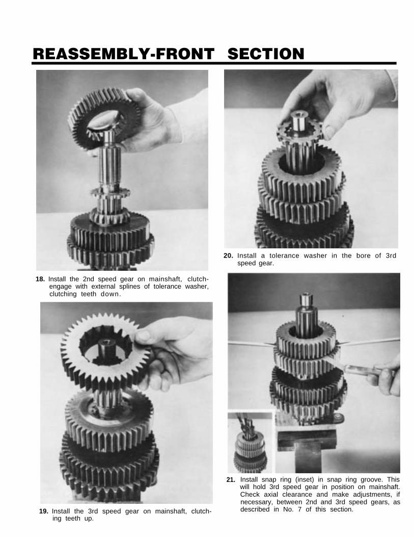
18. Install the 2nd speed gear on mainshaft, clutch-engage with external splines of tolerance washer,clutching teeth down.
19. Install the 3rd speed gear on mainshaft, clutch-ing teeth up.
20. Install a tolerance washer in the bore of 3rdspeed gear.
21. Install snap ring (inset) in snap ring groove. Thiswill hold 3rd speed gear in position on mainshaft.Check axial clearance and make adjustments, ifnecessary, between 2nd and 3rd speed gears, asdescribed in No. 7 of this section.
REASSEMBLY-FRONT SECTION
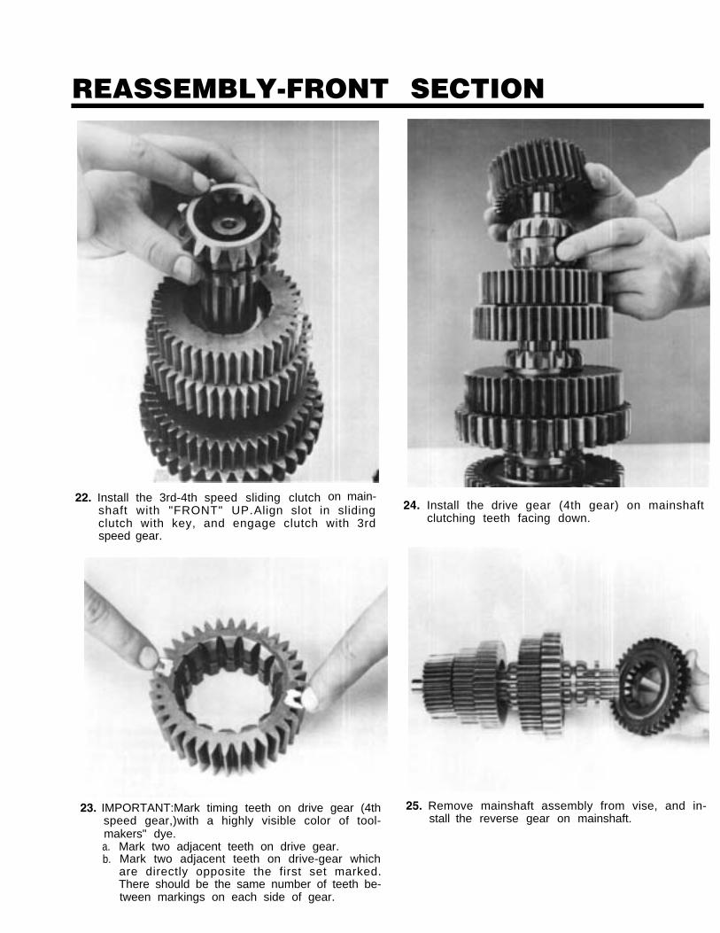
22. Install the 3rd-4th speed sliding clutch on main-shaft with "FRONT" UP. Align slot in slidingclutch with key, and engage clutch with 3rdspeed gear.
23. IMPORTANT:Mark timing teeth on drive gear (4thspeed gear,)with a highly visible color of tool-makers" dye.a.b.
Mark two adjacent teeth on drive gear.Mark two adjacent teeth on drive-gear whichare directly opposite the first set marked.There should be the same number of teeth be-tween markings on each side of gear.
24. Install the drive gear (4th gear) on mainshaftclutching teeth facing down.
25. Remove mainshaft assembly from vise, and in-stall the reverse gear on mainshaft.
REASSEMBLY-FRONT SECTIONF. Partial Installation of
Right Countershaft Assembly
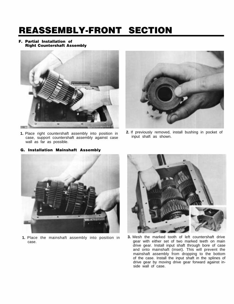
1. Place right countershaft assembly into position incase, support countershaft assembly against casewall as far as possible.
G. Installation Mainshaft Assembly
1. Place the mainshaft assembly into position incase.
2. If previously removed, install bushing in pocket ofinput shaft as shown.
3. Mesh the marked tooth of left countershaft drivegear with either set of two marked teeth on maindrive gear. Install input shaft through bore of caseand onto mainshaft (inset). This will prevent themainshaft assembly from dropping to the bottomof the case. Install the input shaft in the splines ofdrive gear by moving drive gear forward against in-side wall of case.
REASSEMBLY-FRONT SECTION
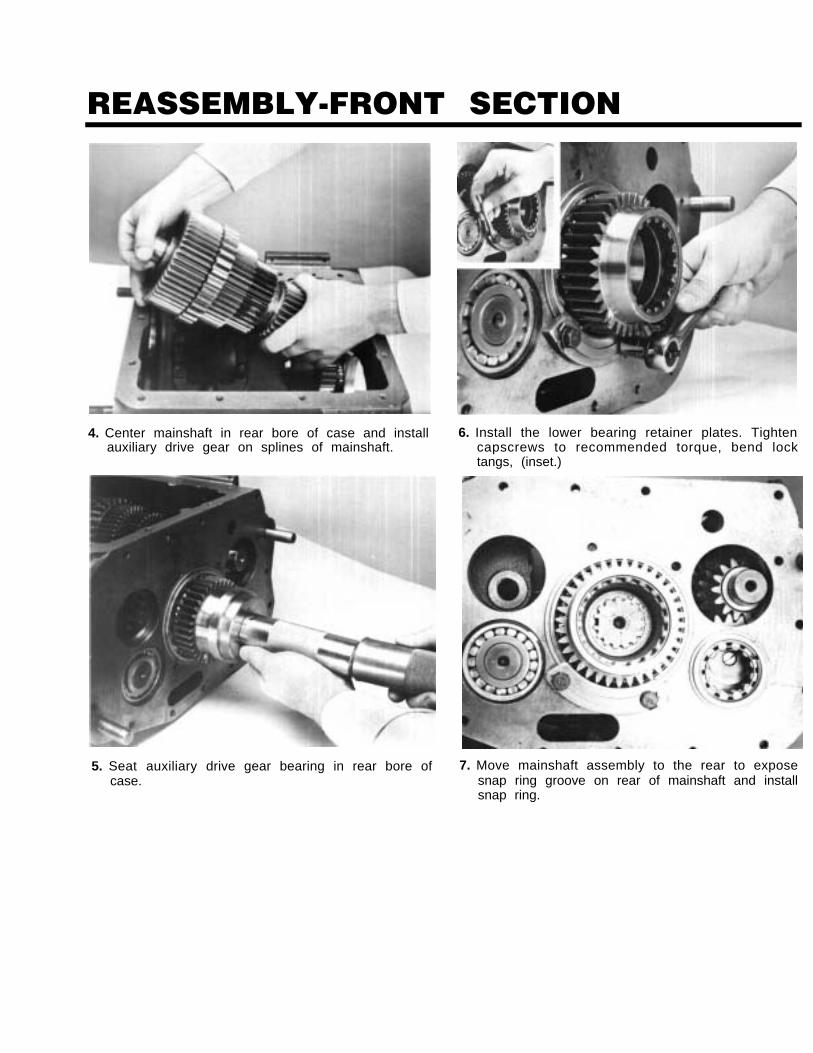
4. Center mainshaft in rear bore of case and installauxiliary drive gear on splines of mainshaft.
5. Seat auxiliary drive gear bearing in rear bore ofcase.
6. Install the lower bearing retainer plates. Tightencapscrews to recommended torque, bend locktangs, (inset.)
7. Move mainshaft assembly to the rear to exposesnap ring groove on rear of mainshaft and installsnap ring.
REASSEMBLY-FRONT SECTION
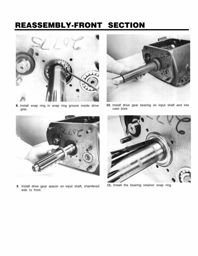
8. Install snap ring in snap ring groove inside drivegear.
9. Install drive gear spacer on input shaft, chamfered
10. Install drive gear bearing on input shaft and intocase bore.
11. Install the bearing retainer snap ring.
side to front.
REASSEMBLY-FRONT SECTION
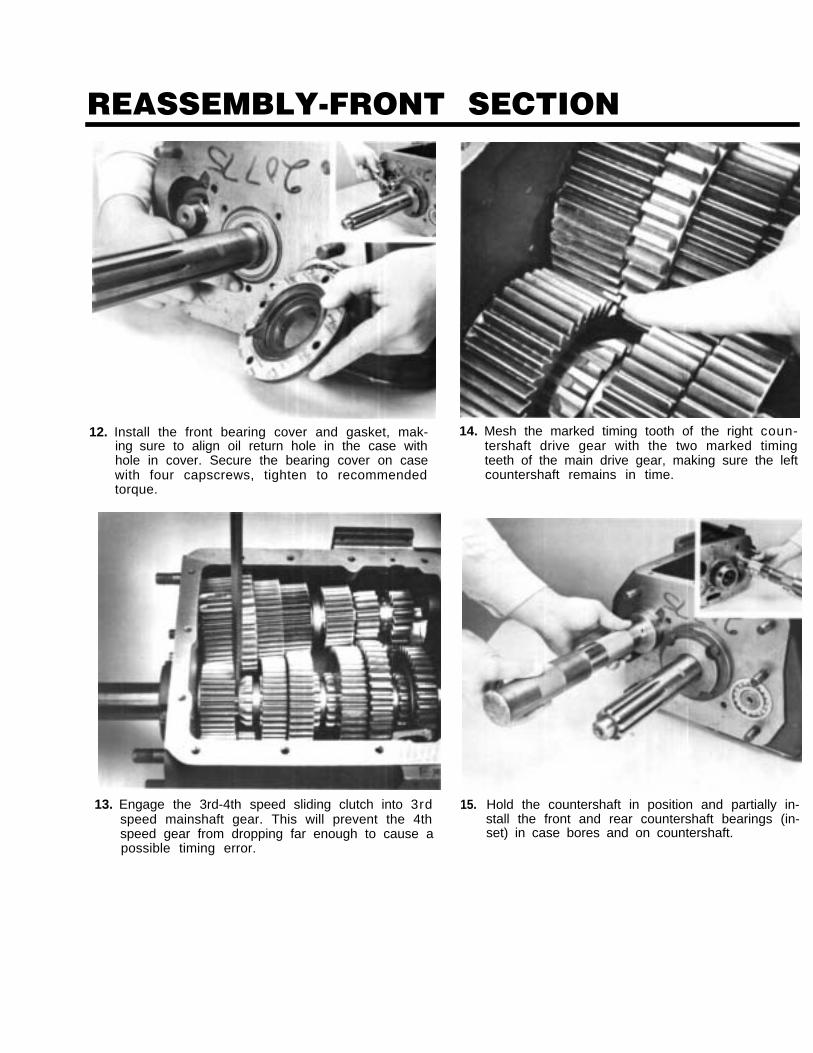
12. Install the front bearing cover and gasket, mak-ing sure to align oil return hole in the case withhole in cover. Secure the bearing cover on casewith four capscrews, tighten to recommendedtorque.
14. Mesh the marked timing tooth of the right coun-tershaft drive gear with the two marked timingteeth of the main drive gear, making sure the leftcountershaft remains in time.
13. Engage the 3rd-4th speed sliding clutch into 3rdspeed mainshaft gear. This will prevent the 4thspeed gear from dropping far enough to cause apossible timing error.
15. Hold the countershaft in position and partially in-stall the front and rear countershaft bearings (in-set) in case bores and on countershaft.
REASSEMBLY-FRONT SECTION
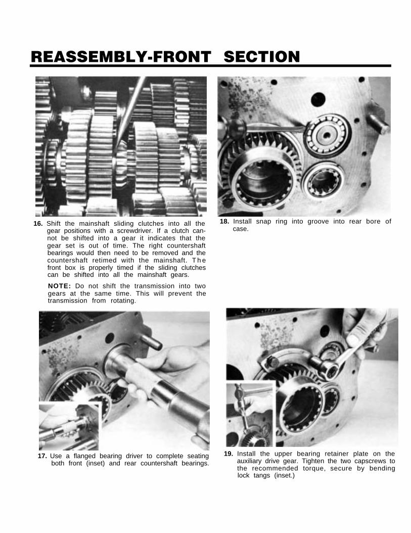
16. Shift the mainshaft sliding clutches into all thegear positions with a screwdriver. If a clutch can-not be shifted into a gear it indicates that thegear set is out of time. The right countershaftbearings would then need to be removed and thecountershaft retimed with the mainshaft. T h efront box is properly timed if the sliding clutchescan be shifted into all the mainshaft gears.
NOTE: Do not shift the transmission into twogears at the same time. This will prevent thetransmission from rotating.
17. Use a flanged bearing driver to complete seatingboth front (inset) and rear countershaft bearings.
18. Install snap ring into groove into rear bore ofcase.
19. Install the upper bearing retainer plate on theauxiliary drive gear. Tighten the two capscrews tothe recommended torque, secure by bendinglock tangs (inset.)
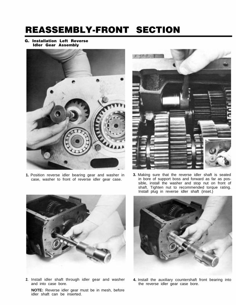
REASSEMBLY-FRONT SECTIONG. Installation Left Reverse
Idler Gear Assembly
1. Position reverse idler bearing gear and washer incase, washer to front of reverse idler gear case.
2. Install idler shaft through idler gear and washerand into case bore.
NOTE: Reverse idler gear must be in mesh, beforeidler shaft can be inserted.
3. Making sure that the reverse idler shaft is seatedin bore of support boss and forward as far as pos-sible, install the washer and stop nut on front ofshaft. Tighten nut to recommended torque rating.Install plug in reverse idler shaft (inset.)
4. Install the auxiliary countershaft front bearing intothe reverse idler gear case bore.
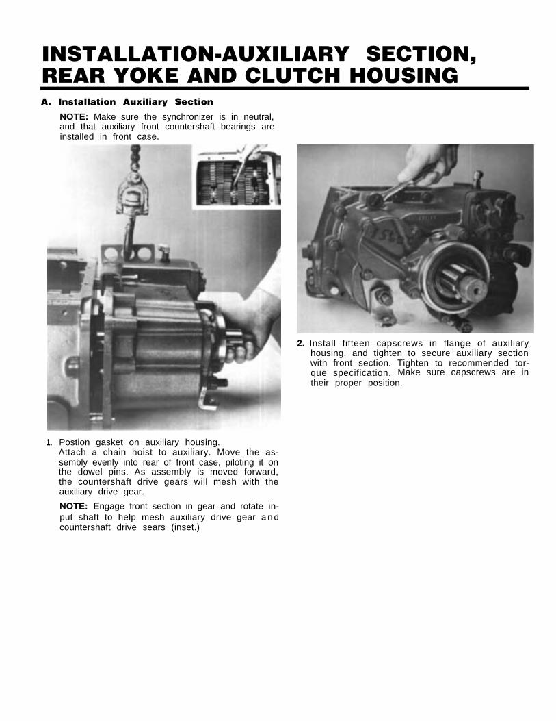
INSTALLATION-AUXILIARY SECTION,REAR YOKE AND CLUTCH HOUSINGA. Installation Auxiliary Section
NOTE: Make sure the synchronizer is in neutral,and that auxiliary front countershaft bearings areinstalled in front case.
1. Postion gasket on auxiliary housing.Attach a chain hoist to auxiliary. Move the as-sembly evenly into rear of front case, piloting it onthe dowel pins. As assembly is moved forward,the countershaft drive gears will mesh with theauxiliary drive gear.
2. Install fifteen capscrews in flange of auxiliaryhousing, and tighten to secure auxiliary sectionwith front section. Tighten to recommended tor-que specification. Make sure capscrews are intheir proper position.
NOTE: Engage front section in gear and rotate in-put shaft to help mesh auxiliary drive gear a n dcountershaft drive sears (inset.)
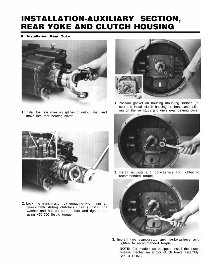
INSTALLATION-AUXILIARY SECTION,REAR YOKE AND CLUTCH HOUSINGB. Installation Rear Yoke
1. Install the rear yoke on splines of output shaft andmove into rear bearing cover.
2. Lock the transmission by engaging two mainshaftgears with sliding clutches (inset.) Install thewasher and nut on output shaft and tighten nutusing 450-500 lbs./ft. torque.
1. Position gasket on housing mounting surface (in-set) and install clutch housing on front case, pilot-ing on the six studs and drive gear bearing cover.
2. Install six nuts and lockwashers and tighten torecommended torque.
3. Instal l two capscrews and lockwashers andtighten to recommended torque.
NOTE: For models so equipped install the clutchrelease mechanism and/or clutch brake assembly.See OPTIONS.
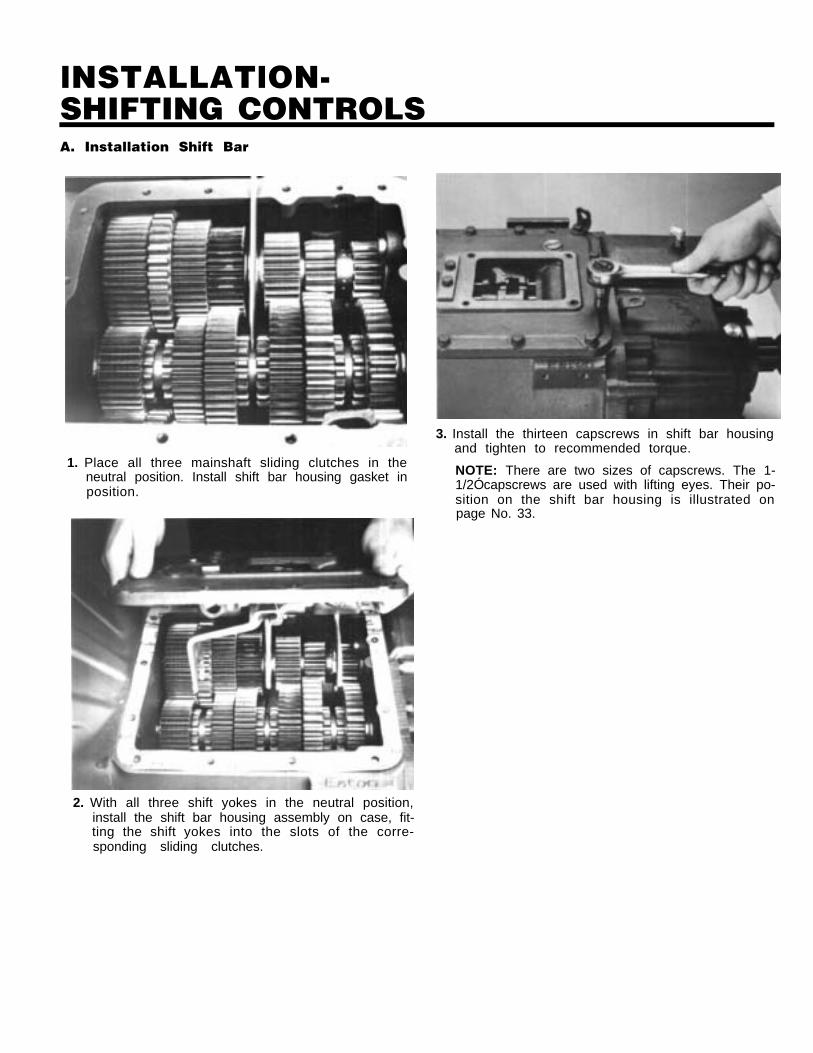
lNSTALLATlON-SHIFTING CONTROLSA. Installation Shift Bar
1. Place all three mainshaft sliding clutches in theneutral position. Install shift bar housing gasket inposition.
3. Install the thirteen capscrews in shift bar housingand tighten to recommended torque.
NOTE: There are two sizes of capscrews. The 1-1/2Ócapscrews are used with lifting eyes. Their po-sition on the shift bar housing is illustrated onpage No. 33.
2. With all three shift yokes in the neutral position,install the shift bar housing assembly on case, fit-ting the shift yokes into the slots of the corre-sponding sliding clutches.
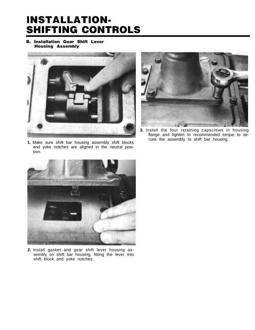
lNSTALLATlON-SHIFTING CONTROLSB. Installation Gear Shift Lever
Housing Assembly
3. Install the four retaining capscrews in housingflange and tighten to recommended torque to se-cure the assembly to shift bar housing.
1. Make sure shift bar housing assembly shift blocksand yoke notches are aligned in the neutral posi-tion.
2. Install gasket and gear shift lever housing as-sembly on shift bar housing, fitting the lever intoshift block and yoke notches.
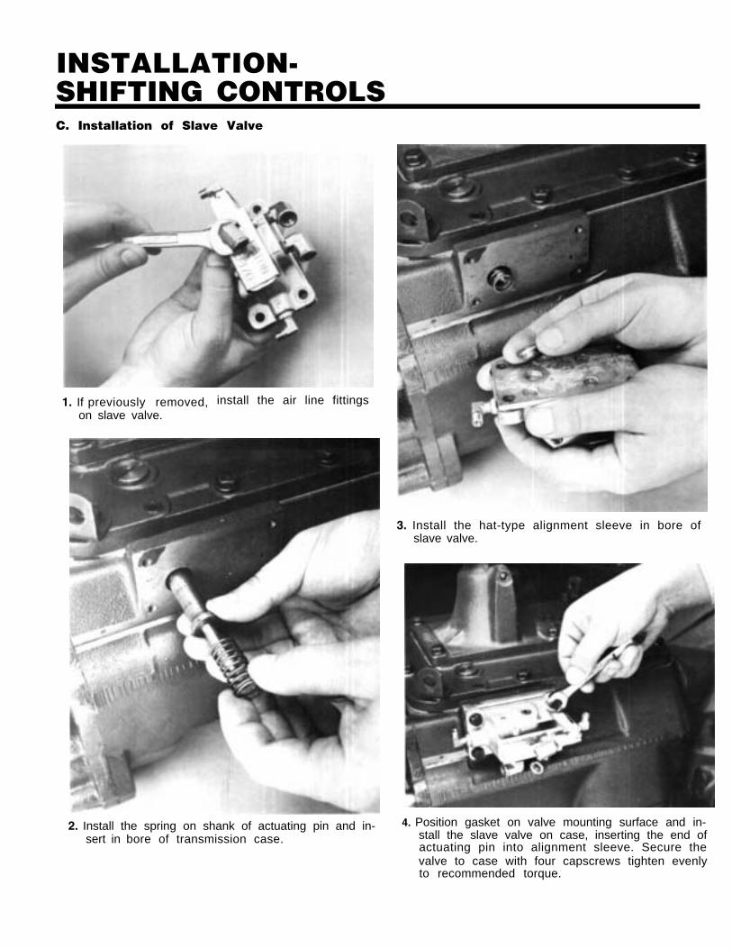
INSTALLATION-SHIFTING CONTROLSC. Installation of Slave Valve
1. If previously removed, install the air line fittingson slave valve.
2. Install the spring on shank of actuating pin and in-sert in bore of transmission case.
3. Install the hat-type alignment sleeve in bore ofslave valve.
4. Position gasket on valve mounting surface and in-stall the slave valve on case, inserting the end ofactuating pin into alignment sleeve. Secure thevalve to case with four capscrews tighten evenlyto recommended torque.
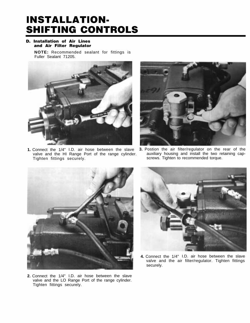
lNSTALLATlON-SHIFTING CONTROLSD. Installation of Air Lines
and Air Filter Regulator
NOTE: Recommended sealant for fittings isFuller Sealant 71205.
1. Connect the 1/4" I.D. air hose between the slavevalve and the HI Range Port of the range cylinder.Tighten fittings securely.
3. Postion the air filter/regulator on the rear of theauxiliary housing and install the two retaining cap-screws. Tighten to recommended torque.
4. Connect the 1/4" I.D. air hose between the slavevalve and the air filter/regulator. Tighten fittingssecurely.
2. Connect the 1/4" I.D. air hose between the slavevalve and the LO Range Port of the range cylinder.Tighten fittings securely.
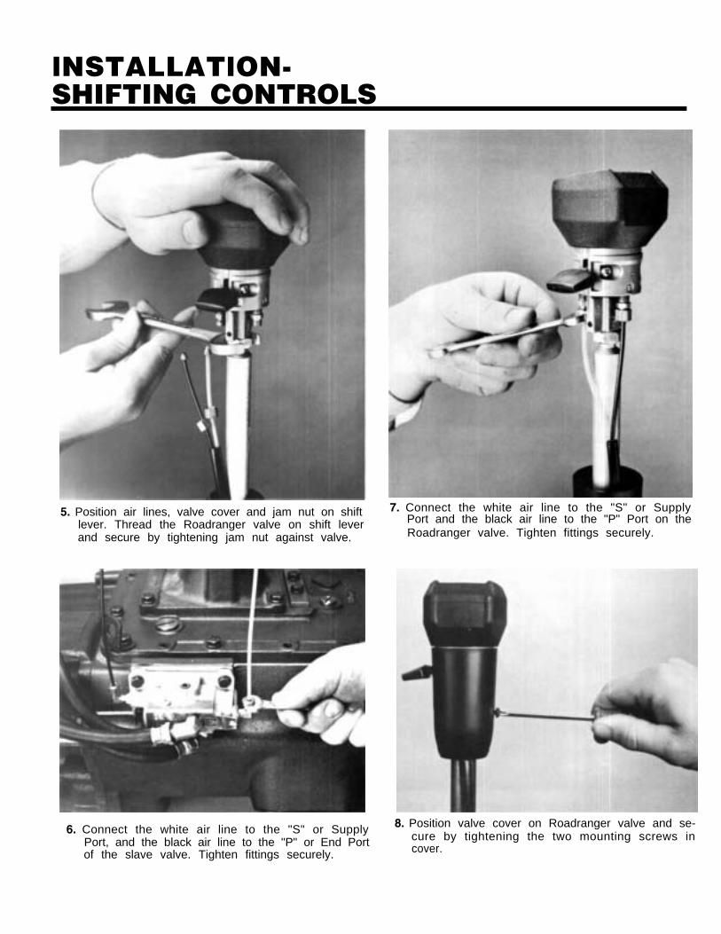
lNSTALLATlON-SHIFTING CONTROLS
5. Position air lines, valve cover and jam nut on shiftlever. Thread the Roadranger valve on shift leverand secure by tightening jam nut against valve.
6. Connect the white air line to the "S" or SupplyPort, and the black air line to the "P" or End Portof the slave valve. Tighten fittings securely.
7. Connect the white air line to the "S" or SupplyPort and the black air line to the "P" Port on theRoadranger valve. Tighten fittings securely.
8. Position valve cover on Roadranger valve and se-cure by tightening the two mounting screws incover.

Fo r spec’ing or service assistance, call 1-80 0-826-HELP (4357) 24 hours a day, 7 days a w eek (Mexico:
001-80 0-826-4357), for mo re time on the road. O r visit our w eb sit e at www .roadr ang er.com .
Eaton Corporation • Truc k Components Operations • P. O. Bo x 4013 • Kalamaz oo, MI 490 03 • U.S.A. • www .roadranger .com
Roadranger: Eaton, Dana and other trusted partner s providing the best products and services in the industry , ensuring more time on the road.
©20 07 Eaton Corporation · All rights reserved.Pr inted in US A
Copyright Eaton and Dana Corporation,2007. EATON AND DANA CORPORA TIONhereby grants its customer s, vendor s, ordistributor s permission to freely copy,reproduce and/or distribute this documentin printed format. It may be copied only in itsentirety without any changes or modifications.THIS INFORMATION IS NOT INTENDEDFOR SALE OR RESALE, AND THIS NOTICEMUST REMAIN ON ALL COPIES.