Embed Size (px)
Citation preview
sandpiperpump.com
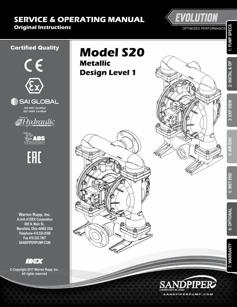
Model S20 Metallic Design Level 1
Warren Rupp, Inc.A Unit of IDEX Corporation
800 N. Main St., Mansfield, Ohio 44902 USA
Telephone 419.524.8388Fax 419.522.7867
SANDPIPERPUMP.COM
© Copyright 2017 Warren Rupp, Inc.All rights reserved
OPTIMIZED PERFORMANCE
Certified Quality
ISO 9001 Certified ISO 14001 Certified
SERVICE & OPERATING MANUALOriginal Instructions
1: P
UMP
SPEC
S2:
INST
AL &
OP
3: E
XP V
IEW
4: A
IR E
ND5:
WET
END
6: O
PTIO
NAL
7: W
ARRA
NTY
s20mdl1sm-rev0217
sandpiperpump.com
IMPORTANT
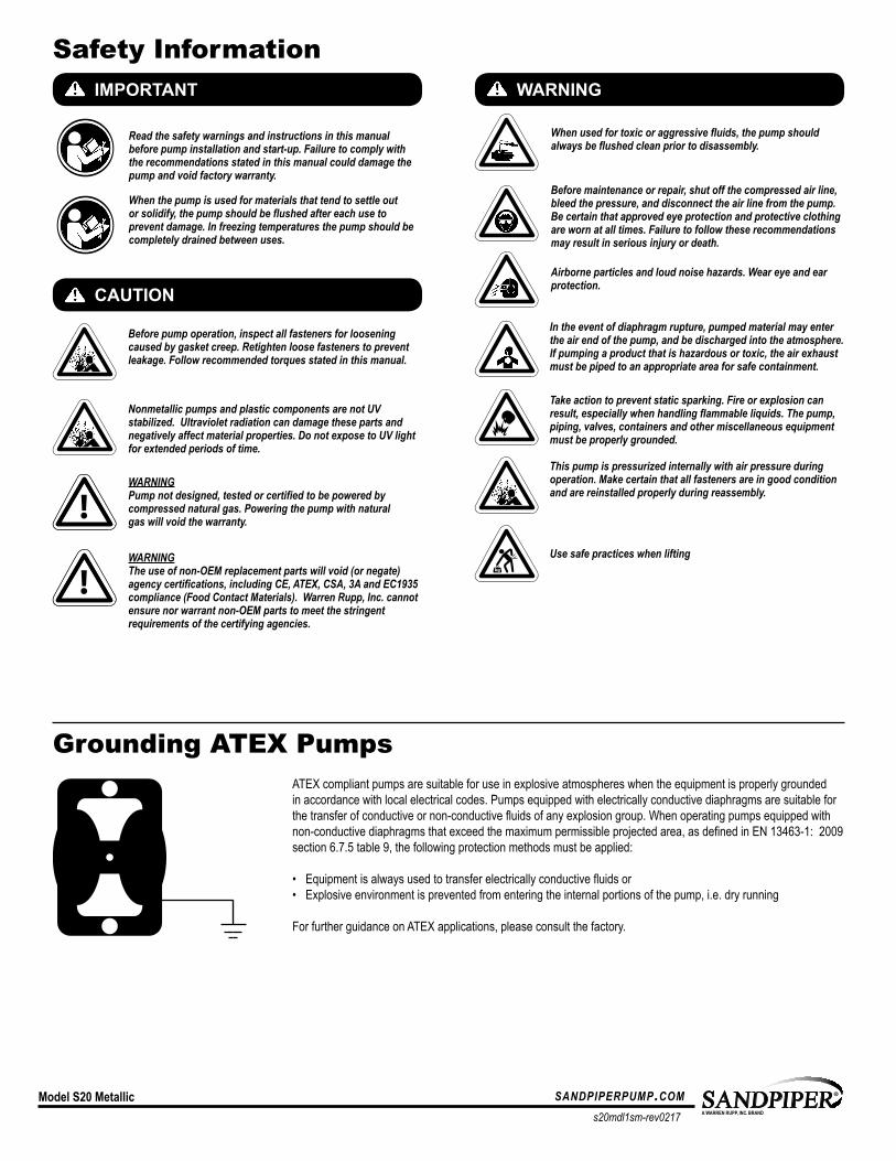
Read the safety warnings and instructions in this manual before pump installation and start-up. Failure to comply with the recommendations stated in this manual could damage the pump and void factory warranty.
When used for toxic or aggressive fluids, the pump should always be flushed clean prior to disassembly.
Airborne particles and loud noise hazards. Wear eye and ear protection.
Before maintenance or repair, shut off the compressed air line, bleed the pressure, and disconnect the air line from the pump. Be certain that approved eye protection and protective clothing are worn at all times. Failure to follow these recommendations may result in serious injury or death.
ATEX compliant pumps are suitable for use in explosive atmospheres when the equipment is properly grounded in accordance with local electrical codes. Pumps equipped with electrically conductive diaphragms are suitable for the transfer of conductive or non-conductive fluids of any explosion group. When operating pumps equipped with non-conductive diaphragms that exceed the maximum permissible projected area, as defined in EN 13463-1: 2009 section 6.7.5 table 9, the following protection methods must be applied:
• Equipment is always used to transfer electrically conductive fluids or• Explosive environment is prevented from entering the internal portions of the pump, i.e. dry running
For further guidance on ATEX applications, please consult the factory.
When the pump is used for materials that tend to settle out or solidify, the pump should be flushed after each use to prevent damage. In freezing temperatures the pump should be completely drained between uses.
Before pump operation, inspect all fasteners for loosening caused by gasket creep. Retighten loose fasteners to prevent leakage. Follow recommended torques stated in this manual.
CAUTION
WARNING
Nonmetallic pumps and plastic components are not UV stabilized. Ultraviolet radiation can damage these parts and negatively affect material properties. Do not expose to UV light for extended periods of time.
Model S20 Metallic
In the event of diaphragm rupture, pumped material may enter the air end of the pump, and be discharged into the atmosphere. If pumping a product that is hazardous or toxic, the air exhaust must be piped to an appropriate area for safe containment.
This pump is pressurized internally with air pressure during operation. Make certain that all fasteners are in good condition and are reinstalled properly during reassembly.
Take action to prevent static sparking. Fire or explosion can result, especially when handling flammable liquids. The pump, piping, valves, containers and other miscellaneous equipment must be properly grounded.
Safety Information
Grounding ATEX Pumps
WARNINGPump not designed, tested or certified to be powered by compressed natural gas. Powering the pump with natural gas will void the warranty.
Use safe practices when liftingkg
WARNINGThe use of non-OEM replacement parts will void (or negate) agency certifications, including CE, ATEX, CSA, 3A and EC1935 compliance (Food Contact Materials). Warren Rupp, Inc. cannot ensure nor warrant non-OEM parts to meet the stringent requirements of the certifying agencies.
UNIVERSAL ALL AODD
s20mdl1sm-rev0217
sandpiperpump.com Model S20 Metallic
Table of Contents
SECTION 1: PUMP SPECIFICATIONS ................1 • Explanation of Nomenclature • Performance • Materials • Dimensional Drawings
SECTION 2: INSTALLATION & OPERATION ......5 • Principle of Pump Operation • Recommended Installation Guide • Troubleshooting Guide
SECTION 3: EXPLODED VIEW ...........................8 • Composite Repair Parts Drawing • Composite Repair Parts List • Material Codes
SECTION 4: AIR END .......................................11 • Air Distribution Valve Assembly • Air Valve with Stroke Indicator Assembly • Pilot Valve Assembly • Intermediate Assembly
SECTION 5: WET END .....................................17 • Diaphragm Drawings • Diaphragm Servicing
SECTION 6: OPTIONAL CONFIGURATIONS ....19 • Solenoid Shifted Air Valve
SECTION 7: WARRANTY & CERTIFICATES ....20 • Warranty • CE Declaration of Conformity - Machinery • ATEX Declaration of Conformity
MODEL SPECIFIC
1: P
UMP
SPEC
S2:
INST
AL &
OP
3: E
XP V
IEW
4: A
IR E
ND5:
WET
END
6: O
PTIO
NAL
7: W
ARRA
NTY
s20mdl1sm-rev0217
sandpiperpump.com1 • Model S20 Metallic
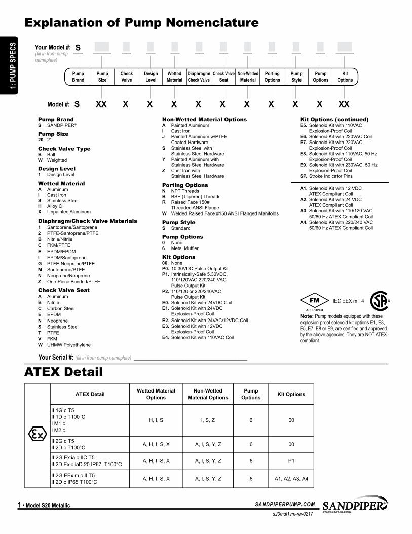
Explanation of Pump Nomenclature
ATEX Detail
Non-Wetted Material Options A Painted Aluminum I Cast Iron J Painted Aluminum w/PTFE Coated Hardware S Stainless Steel with Stainless Steel Hardware Y Painted Aluminum with Stainless Steel Hardware Z Cast Iron with Stainless Steel Hardware
Porting Options N NPT Threads B BSP (Tapered) Threads R Raised Face 150# Threaded ANSI Flange W Welded Raised Face #150 ANSI Flanged Manifolds
Pump Style S Standard
Pump Options 0 None 6 MetalMuffler
Kit Options 00. None P0. 10.30VDC Pulse Output Kit P1. Intrinsically-Safe 5.30VDC, 110/120VAC 220/240 VAC Pulse Output Kit P2. 110/120 or 220/240VAC Pulse Output Kit E0. Solenoid Kit with 24VDC Coil E1. Solenoid Kit with 24VDC Explosion-Proof Coil E2. Solenoid Kit with 24VAC/12VDC Coil E3. Solenoid Kit with 12VDC Explosion-Proof Coil E4. Solenoid Kit with 110VAC Coil
Pump Brand S SANDPIPER®
Pump Size 20 2"
Check Valve Type B Ball W Weighted
Design Level 1 Design Level
Wetted Material A Aluminum I Cast Iron S Stainless Steel H Alloy C X Unpainted Aluminum
Diaphragm/Check Valve Materials 1 Santoprene/Santoprene 2 PTFE-Santoprene/PTFE B Nitrile/Nitrile C FKM/PTFE E EPDM/EPDM I EPDM/Santoprene G PTFE-Neoprene/PTFE M Santoprene/PTFE N Neoprene/Neoprene Z One-Piece Bonded/PTFE
Check Valve Seat A Aluminum B Nitrile C Carbon Steel E EPDM N Neoprene S Stainless Steel T PTFE V FKM W UHMW Polyethylene
Your Serial #: (fill in from pump nameplate) _____________________________________
Pump Pump Check Design Wetted Diaphragm/ Check Valve Non-Wetted Porting Pump Pump Kit Brand Size Valve Level Material Check Valve Seat Material Options Style Options Options
S XX X X X X X X X X X XXModel #:
S __ ____ __ __ __ __ __ __ __ __ __ ____(fill in from pump nameplate)
Your Model #:
Kit Options (continued) E5. Solenoid Kit with 110VAC Explosion-Proof Coil E6. Solenoid Kit with 220VAC Coil E7. Solenoid Kit with 220VAC Explosion-Proof Coil E8. Solenoid Kit with 110VAC, 50 Hz Explosion-Proof Coil E9. Solenoid Kit with 230VAC, 50 Hz Explosion-Proof Coil SP. Stroke Indicator Pins
A1. Solenoid Kit with 12 VDC ATEX Compliant Coil A2. Solenoid Kit with 24 VDC ATEX Compliant Coil A3. Solenoid Kit with 110/120 VAC 50/60 Hz ATEX Compliant Coil A4. Solenoid Kit with 220/240 VAC 50/60 Hz ATEX Compliant Coil
IEC EEX m T4
Note: Pump models equipped with these explosion-proof solenoid kit options E1, E3, E5, E7, E8 or E9, are certified and approved by the above agencies. They are NOT ATEX compliant.
S05 S05, S1FATEX Detail Wetted Material
OptionsNon-Wetted
Material OptionsPump
Options Kit Options ATEX Detail Wetted Material Options
Non-Wetted Material Options
Pump Options Kit Options
S1F, M1F remove wetted material option X S15, S20
ATEX Detail Wetted Material Options
Non-Wetted Material Options
Pump Options Kit Options ATEX Detail Wetted Material
OptionsNon-Wetted
Material OptionsPump
Options Kit Options
S15, S20, S30
ATEX Detail Wetted Material Options
Non-Wetted Material Options
Pump Options Kit Options
PB 1/4ATEX Detail Construction Muffler Options Options
II 1G c T5II 1D c T100°CI M1 cI M2 c
CA 00
II 2G c T5II 2D c T100°C CA 00
II 2G Ex ia c IIC T5II 2D Ex c iaD 20 IP67 T100°C CA P1
Metal
Integral
Integral
II 1G c T5II 1D c T100°CI M1 cI M2 c
II 2G c T5II 2D c T100°CII 2G Ex ia c IIC T5II 2D Ex c iaD 20 IP67 T100°C
II 2G EEx m c II T5 II 2D c IP65 T100°C
A, H, S A, C, Y **0, 6 P1
00
A, H, S A, C, Y **0, 6 A1, A2, A3, A4
H, S C 6 00
A, H, S A, C, Y **0, 6
A1, A2, A3, A4
**Pump option 0 is only ATEX compliant with non-wetted material option C
00
II 2G Ex ia c IIC T5II 2D Ex c iaD 20 IP67 T100°C A, H, I, S, X A, I, Y, Z 6 P1
II 1G c T5II 1D c T100°CI M1 cI M2 c
H, I, S I, Z 6 00
II 2G c T5II 2D c T100°C A, H, I, S, X A, I, Y, Z 6
II 1G c T5II 1D c T100°CI M1 cI M2 c
H, I, S I, S, Z 6 00
II 2G c T5II 2D c T100°C A, H, I, S, X A, I, S, Y, Z 6
C 0, 6 A1, A2, A3, A4
II 1G c T5II 1D c T100°CI M1 cI M2 c
C, V C 6 00
II 2G EEx m c II T5 II 2D c IP65 T100°C A, H, I, S, X A, I, S, Y, Z 6 A1, A2, A3, A4
00
II 2G Ex ia c IIC T5II 2D Ex c iaD 20 IP67 T100°C A, H, I, S, X A, I, S, Y, Z 6 P1
II 2G EEx m c II T5 II 2D c IP65 T100°C A, H, I, S, X A, I, Y, Z 6
0, 6 P1
II 1G c T5II 1D c T100°CI M1 cI M2 c
C C 6 00
II 2G c T5II 2D c T100°C C C 0, 6
METALLIC
000, 6 CC, VII 2G c T5II 2D c T100°C
II 2G EEx m c II T5 II 2D c IP65 T100°C C C 0, 6
II 2G Ex ia c IIC T5II 2D Ex c iaD 20 IP67 T100°C C, V C 0, 6 P1
II 2G EEx m c II T5 II 2D c IP65 T100°C C, V
A1, A2, A3, A4
NON-METALLIC
00
II 2G Ex ia c IIC T5II 2D Ex c iaD 20 IP67 T100°C C C
MODEL SPECIFIC
1: P
UMP
SPEC
S
s20mdl1sm-rev0217
sandpiperpump.com Model S20 Metallic • 2
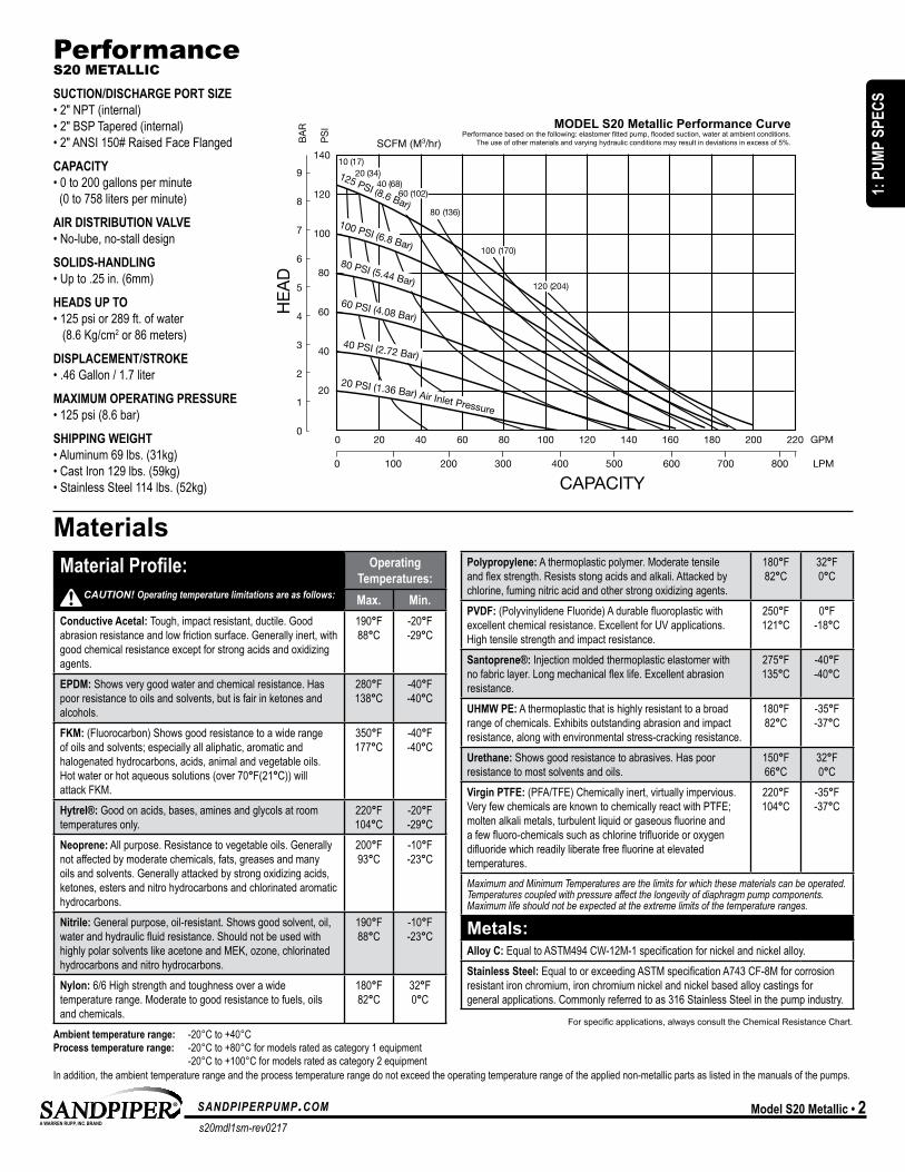
PerformanceS20 METALLIC
SUCTION/DISCHARGE PORT SIZE• 2" NPT (internal)• 2" BSP Tapered (internal)• 2" ANSI 150# Raised Face Flanged
CAPACITY• 0 to 200 gallons per minute (0 to 758 liters per minute)
AIR DISTRIBUTION VALVE• No-lube, no-stall design
SOLIDS-HANDLING• Up to .25 in. (6mm)
HEADS UP TO• 125 psi or 289 ft. of water (8.6 Kg/cm2 or 86 meters)
DISPLACEMENT/STROKE• .46 Gallon / 1.7 liter
MAXIMUM OPERATING PRESSURE• 125 psi (8.6 bar)
SHIPPING WEIGHT• Aluminum 69 lbs. (31kg)• Cast Iron 129 lbs. (59kg)• Stainless Steel 114 lbs. (52kg)
MaterialsMaterial Profile: Operating
Temperatures:Max. Min.
Conductive Acetal: Tough, impact resistant, ductile. Good abrasion resistance and low friction surface. Generally inert, with good chemical resistance except for strong acids and oxidizing agents.
190°F88°C
-20°F-29°C
EPDM: Shows very good water and chemical resistance. Has poor resistance to oils and solvents, but is fair in ketones and alcohols.
280°F138°C
-40°F-40°C
FKM: (Fluorocarbon) Shows good resistance to a wide range of oils and solvents; especially all aliphatic, aromatic and halogenated hydrocarbons, acids, animal and vegetable oils. Hot water or hot aqueous solutions (over 70°F(21°C)) will attack FKM.
350°F177°C
-40°F-40°C
Hytrel®: Good on acids, bases, amines and glycols at room temperatures only.
220°F104°C
-20°F-29°C
Neoprene: All purpose. Resistance to vegetable oils. Generally not affected by moderate chemicals, fats, greases and many oils and solvents. Generally attacked by strong oxidizing acids, ketones, esters and nitro hydrocarbons and chlorinated aromatic hydrocarbons.
200°F93°C
-10°F-23°C
Nitrile: General purpose, oil-resistant. Shows good solvent, oil, water and hydraulic fluid resistance. Should not be used with highly polar solvents like acetone and MEK, ozone, chlorinated hydrocarbons and nitro hydrocarbons.
190°F88°C
-10°F-23°C
Nylon: 6/6 High strength and toughness over a wide temperature range. Moderate to good resistance to fuels, oils and chemicals.
180°F82°C
32°F0°C
Polypropylene: A thermoplastic polymer. Moderate tensile and flex strength. Resists stong acids and alkali. Attacked by chlorine, fuming nitric acid and other strong oxidizing agents.
180°F82°C
32°F0°C
PVDF: (Polyvinylidene Fluoride) A durable fluoroplastic with excellent chemical resistance. Excellent for UV applications. High tensile strength and impact resistance.
250°F121°C
0°F-18°C
Santoprene®: Injection molded thermoplastic elastomer with no fabric layer. Long mechanical flex life. Excellent abrasion resistance.
275°F135°C
-40°F-40°C
UHMW PE: A thermoplastic that is highly resistant to a broad range of chemicals. Exhibits outstanding abrasion and impact resistance, along with environmental stress-cracking resistance.
180°F82°C
-35°F-37°C
Urethane: Shows good resistance to abrasives. Has poor resistance to most solvents and oils.
150°F66°C
32°F0°C
Virgin PTFE: (PFA/TFE) Chemically inert, virtually impervious. Very few chemicals are known to chemically react with PTFE; molten alkali metals, turbulent liquid or gaseous fluorine and a few fluoro-chemicals such as chlorine trifluoride or oxygen difluoride which readily liberate free fluorine at elevated temperatures.
220°F104°C
-35°F-37°C
Maximum and Minimum Temperatures are the limits for which these materials can be operated. Temperatures coupled with pressure affect the longevity of diaphragm pump components. Maximum life should not be expected at the extreme limits of the temperature ranges.
Metals:Alloy C: Equal to ASTM494 CW-12M-1 specification for nickel and nickel alloy.Stainless Steel: Equal to or exceeding ASTM specification A743 CF-8M for corrosion resistant iron chromium, iron chromium nickel and nickel based alloy castings for general applications. Commonly referred to as 316 Stainless Steel in the pump industry.
Forspecificapplications,alwaysconsulttheChemicalResistanceChart.
CAUTION! Operating temperature limitations are as follows:
Ambient temperature range: -20°C to +40°C Process temperature range: -20°C to +80°C for models rated as category 1 equipment -20°C to +100°C for models rated as category 2 equipmentIn addition, the ambient temperature range and the process temperature range do not exceed the operating temperature range of the applied non-metallic parts as listed in the manuals of the pumps.
CAPACITY
GPM
LPM1000
PS
I
HE
AD
BA
R
1
2
3
4
5
6
7
8
9
0
20
40
60
80
100
120
140
0 20 40 60 80 100 120 140 160 180 200 220
200 300 400 500 600 700 800
MODEL S20 Metallic Performance CurvePerformance based on the following: elastomer fitted pump, flooded suction, water at ambient conditions.
The use of other materials and varying hydraulic conditions may result in deviations in excess of 5%.
120 PSI (8 Bar)
80 PSI (5.44 Bar)
60 PSI (4.08 Bar)
40 PSI (2.72 Bar)
20 PSI (1.36 Bar) Air Inlet Pressure
100 PSI (6.8 Bar)
125 PSI (8.6 Bar)
80 PSI (5.44 Bar)
60 PSI (4.08 Bar)
40 PSI (2.72 Bar)
20 PSI (1.36 Bar) Air Inlet Pressure
100 PSI (6.8 Bar)
20 (34)10 (17)
40 (68)
80 (136)
100 (170)
120 (204)
60 (102)
MODEL SPECIFIC UNIVERSAL ALL AODD
1: P
UMP
SPEC
S
s20mdl1sm-rev0217
sandpiperpump.com3 • Model S20 Metallic
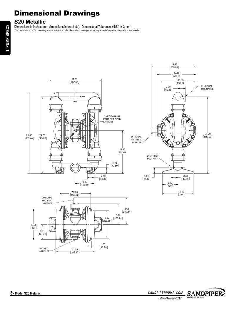
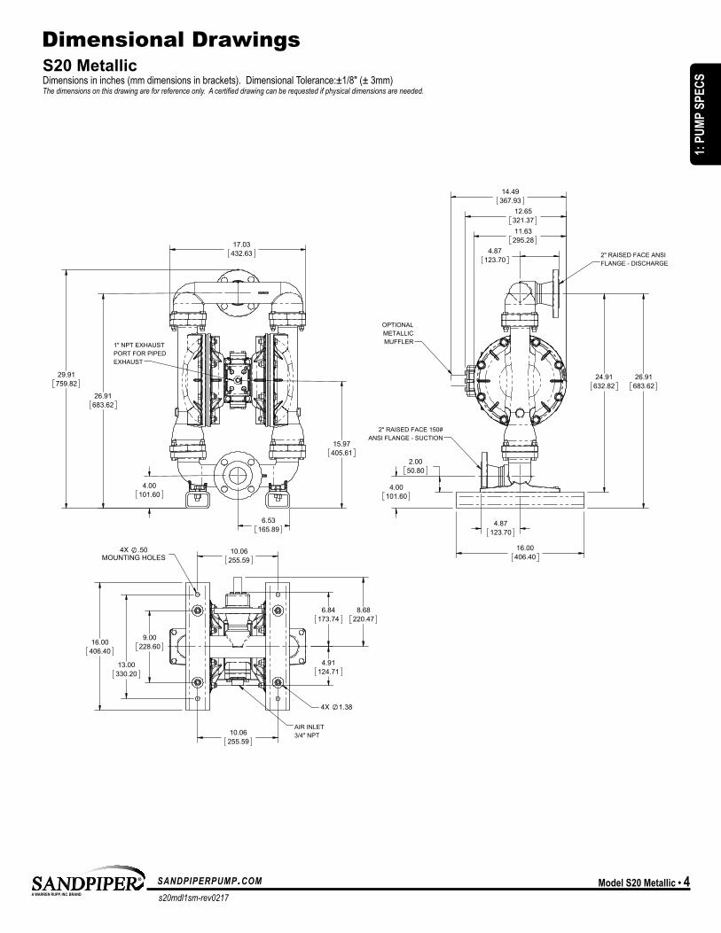
S20 Metallic Dimensions in inches (mm dimensions in brackets). Dimensional Tolerance:±1/8" (± 3mm) The dimensions on this drawing are for reference only. A certified drawing can be requested if physical dimensions are needed.
Dimensional Drawings
17.03432.63
24.79629.69
13.85351.69
2.1855.47
6.12155.50
1.8847.69
26.36669.44
1" NPT EXHAUSTPORT FOR PIPEDEXHAUST
10.00254
5.00127
24.79629.69
2.3860.45
2.2557.15
1.8847.69
11.63295.34
12.66321.44
14.49368.05
2" NPT/BSPSUCTION
2" NPT/BSPDISCHARGE
OPTIONALMETALLICMUFFLER
9.00228.60
10.06255.52
12.59319.77
10.00254
.5012.70
6.84173.74
4.91124.71
8.68220.41
3/4" NPT AIR INLET
OPTIONALMETALLICMUFFLER
MODEL SPECIFIC
1: P
UMP
SPEC
S
s20mdl1sm-rev0217
sandpiperpump.com Model S20 Metallic • 4
S20 Metallic Dimensions in inches (mm dimensions in brackets). Dimensional Tolerance:±1/8" (± 3mm) The dimensions on this drawing are for reference only. A certified drawing can be requested if physical dimensions are needed.
Dimensional Drawings
26.91683.62
4.00101.60
17.03432.63
6.53165.89
15.97405.61
29.91759.82
1" NPT EXHAUSTPORT FOR PIPEDEXHAUST
4.87123.70
26.91683.62
24.91632.82
4.00101.60
2.0050.80
16.00406.40
4.87123.70
14.49367.93
11.63295.28
12.65321.37
2" RAISED FACE ANSIFLANGE - DISCHARGE
2" RAISED FACE 150#ANSI FLANGE - SUCTION
6.84173.74
13.00330.20
16.00406.40
4X .50MOUNTING HOLES
10.06255.59
9.00228.60
4X 1.38
10.06255.59
4.91124.71
8.68220.47
AIR INLET3/4" NPT
OPTIONALMETALLICMUFFLER
1: P
UMP
SPEC
S
s20mdl1sm-rev0217
sandpiperpump.com5 • Model S20 Metallic
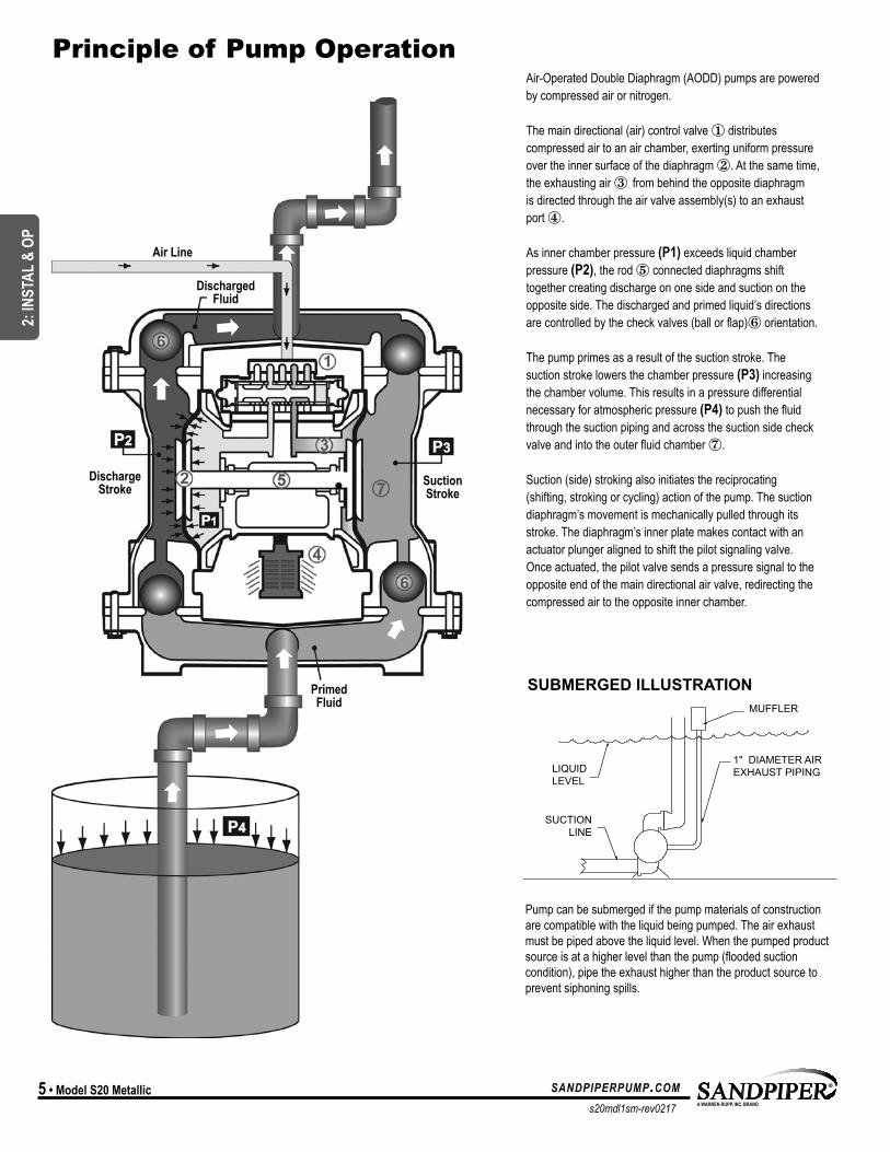
Air-Operated Double Diaphragm (AODD) pumps are powered by compressed air or nitrogen.
The main directional (air) control valve ① distributes compressed air to an air chamber, exerting uniform pressure over the inner surface of the diaphragm ②. At the same time, the exhausting air ③ from behind the opposite diaphragm is directed through the air valve assembly(s) to an exhaust port ④.
As inner chamber pressure (P1) exceeds liquid chamber pressure (P2), the rod ⑤ connected diaphragms shift together creating discharge on one side and suction on the opposite side. The discharged and primed liquid’s directions are controlled by the check valves (ball or flap)⑥ orientation.
The pump primes as a result of the suction stroke. The suction stroke lowers the chamber pressure (P3) increasing the chamber volume. This results in a pressure differential necessary for atmospheric pressure (P4) to push the fluid through the suction piping and across the suction side check valve and into the outer fluid chamber ⑦.
Suction (side) stroking also initiates the reciprocating (shifting, stroking or cycling) action of the pump. The suction diaphragm’s movement is mechanically pulled through its stroke. The diaphragm’s inner plate makes contact with an actuator plunger aligned to shift the pilot signaling valve. Once actuated, the pilot valve sends a pressure signal to the opposite end of the main directional air valve, redirecting the compressed air to the opposite inner chamber.
Principle of Pump Operation
Air Line
Discharged Fluid
DischargeStroke Suction
Stroke
PrimedFluid
SAFE AIREXHAUSTDISPOSALAREA
PUMP INSTALLATION AREA
1" DIAMETER AIREXHAUST PIPING
1" DIAMETER AIREXHAUST PIPING
1" DIAMETER AIREXHAUST PIPING
MUFFLER
LIQUIDLEVEL
SUCTIONLINE
LIQUIDLEVEL
SUCTIONLINE
MUFFLER
MUFFLER
SUBMERGED ILLUSTRATION
Pump can be submerged if the pump materials of construction are compatible with the liquid being pumped. The air exhaust must be piped above the liquid level. When the pumped product source is at a higher level than the pump (flooded suction condition), pipe the exhaust higher than the product source to prevent siphoning spills.
UNIVERSAL ALL AODD
2: IN
STAL
& O
P
s20mdl1sm-rev0217
sandpiperpump.com Model S20 Metallic • 6
Principle of Pump Operation
SUBMERGED ILLUSTRATION
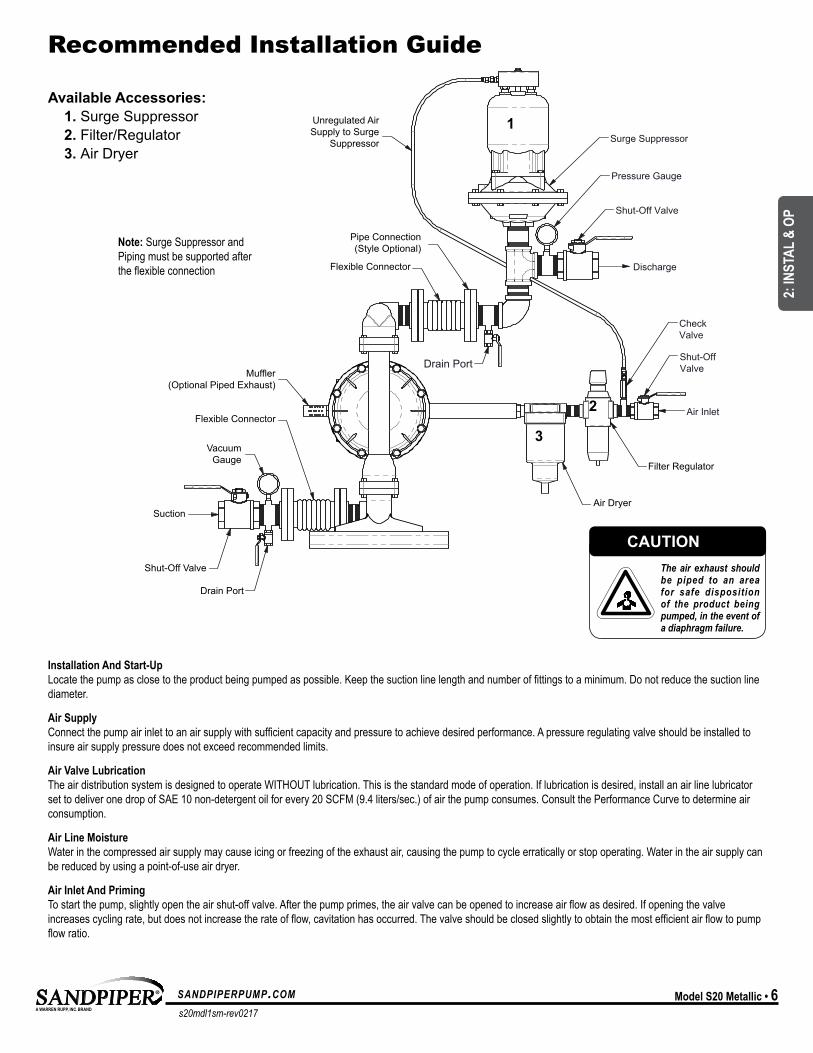
Installation And Start-Up Locate the pump as close to the product being pumped as possible. Keep the suction line length and number of fittings to a minimum. Do not reduce the suction line diameter.
Air Supply Connect the pump air inlet to an air supply with sufficient capacity and pressure to achieve desired performance. A pressure regulating valve should be installed to insure air supply pressure does not exceed recommended limits.
Air Valve Lubrication The air distribution system is designed to operate WITHOUT lubrication. This is the standard mode of operation. If lubrication is desired, install an air line lubricator set to deliver one drop of SAE 10 non-detergent oil for every 20 SCFM (9.4 liters/sec.) of air the pump consumes. Consult the Performance Curve to determine air consumption.
Air Line Moisture Water in the compressed air supply may cause icing or freezing of the exhaust air, causing the pump to cycle erratically or stop operating. Water in the air supply can be reduced by using a point-of-use air dryer.
Air Inlet And Priming To start the pump, slightly open the air shut-off valve. After the pump primes, the air valve can be opened to increase air flow as desired. If opening the valve increases cycling rate, but does not increase the rate of flow, cavitation has occurred. The valve should be closed slightly to obtain the most efficient air flow to pump flow ratio.
Surge Suppressor
Shut-Off Valve
Pressure Gauge
Drain PortShut-OffValve
CheckValve
Air Inlet
Discharge
Unregulated AirSupply to Surge
Suppressor
Pipe Connection(Style Optional)
Flexible Connector
Flexible Connector
VacuumGauge
Suction
Shut-Off Valve
Drain Port
Air Dryer
Filter Regulator
Muffler(Optional Piped Exhaust)
Recommended Installation Guide
Available Accessories: 1. Surge Suppressor 2. Filter/Regulator 3. Air Dryer
1
2
3
Note: Surge Suppressor and Piping must be supported after the flexible connection
CAUTIONThe air exhaust should be piped to an area for safe disposition of the product being pumped, in the event of a diaphragm failure.
UNIVERSAL ALL AODD, EXCEPT FLAP
2: IN
STAL
& O
P
s20mdl1sm-rev0217
sandpiperpump.com7 • Model S20 Metallic
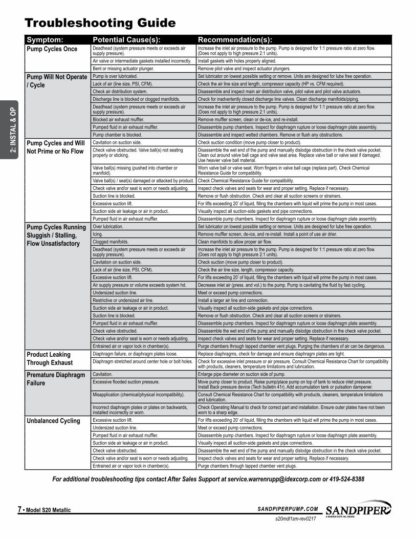
Troubleshooting Guide
For additional troubleshooting tips contact After Sales Support at [email protected] or 419-524-8388
Symptom: Potential Cause(s): Recommendation(s):Pump Cycles Once Deadhead (system pressure meets or exceeds air
supply pressure).Increase the inlet air pressure to the pump. Pump is designed for 1:1 pressure ratio at zero flow. (Does not apply to high pressure 2:1 units).
Air valve or intermediate gaskets installed incorrectly. Install gaskets with holes properly aligned.Bent or missing actuator plunger. Remove pilot valve and inspect actuator plungers.
Pump Will Not Operate / Cycle
Pump is over lubricated. Set lubricator on lowest possible setting or remove. Units are designed for lube free operation.Lack of air (line size, PSI, CFM). Check the air line size and length, compressor capacity (HP vs. CFM required).Check air distribution system. Disassemble and inspect main air distribution valve, pilot valve and pilot valve actuators. Discharge line is blocked or clogged manifolds. Check for inadvertently closed discharge line valves. Clean discharge manifolds/piping.Deadhead (system pressure meets or exceeds air supply pressure).
Increase the inlet air pressure to the pump. Pump is designed for 1:1 pressure ratio at zero flow. (Does not apply to high pressure 2:1 units).
Blocked air exhaust muffler. Remove muffler screen, clean or de-ice, and re-install. Pumped fluid in air exhaust muffler. Disassemble pump chambers. Inspect for diaphragm rupture or loose diaphragm plate assembly. Pump chamber is blocked. Disassemble and inspect wetted chambers. Remove or flush any obstructions.
Pump Cycles and Will Not Prime or No Flow
Cavitation on suction side. Check suction condition (move pump closer to product).Check valve obstructed. Valve ball(s) not seating properly or sticking.
Disassemble the wet end of the pump and manually dislodge obstruction in the check valve pocket. Clean out around valve ball cage and valve seat area. Replace valve ball or valve seat if damaged. Use heavier valve ball material.
Valve ball(s) missing (pushed into chamber or manifold).
Worn valve ball or valve seat. Worn fingers in valve ball cage (replace part). Check Chemical Resistance Guide for compatibility.
Valve ball(s) / seat(s) damaged or attacked by product. Check Chemical Resistance Guide for compatibility.Check valve and/or seat is worn or needs adjusting. Inspect check valves and seats for wear and proper setting. Replace if necessary. Suction line is blocked. Remove or flush obstruction. Check and clear all suction screens or strainers.Excessive suction lift. For lifts exceeding 20’ of liquid, filling the chambers with liquid will prime the pump in most cases.Suction side air leakage or air in product. Visually inspect all suction-side gaskets and pipe connections.Pumped fluid in air exhaust muffler. Disassemble pump chambers. Inspect for diaphragm rupture or loose diaphragm plate assembly.
Pump Cycles Running Sluggish / Stalling, Flow Unsatisfactory
Over lubrication. Set lubricator on lowest possible setting or remove. Units are designed for lube free operation.Icing. Remove muffler screen, de-ice, and re-install. Install a point of use air drier. Clogged manifolds. Clean manifolds to allow proper air flow.Deadhead (system pressure meets or exceeds air supply pressure).
Increase the inlet air pressure to the pump. Pump is designed for 1:1 pressure ratio at zero flow. (Does not apply to high pressure 2:1 units).
Cavitation on suction side. Check suction (move pump closer to product).Lack of air (line size, PSI, CFM). Check the air line size, length, compressor capacity.Excessive suction lift. For lifts exceeding 20’ of liquid, filling the chambers with liquid will prime the pump in most cases.Air supply pressure or volume exceeds system hd. Decrease inlet air (press. and vol.) to the pump. Pump is cavitating the fluid by fast cycling. Undersized suction line. Meet or exceed pump connections. Restrictive or undersized air line. Install a larger air line and connection. Suction side air leakage or air in product. Visually inspect all suction-side gaskets and pipe connections.Suction line is blocked. Remove or flush obstruction. Check and clear all suction screens or strainers.Pumped fluid in air exhaust muffler. Disassemble pump chambers. Inspect for diaphragm rupture or loose diaphragm plate assembly. Check valve obstructed. Disassemble the wet end of the pump and manually dislodge obstruction in the check valve pocket. Check valve and/or seat is worn or needs adjusting. Inspect check valves and seats for wear and proper setting. Replace if necessary.Entrained air or vapor lock in chamber(s). Purge chambers through tapped chamber vent plugs. Purging the chambers of air can be dangerous.
Product Leaking Through Exhaust
Diaphragm failure, or diaphragm plates loose. Replace diaphragms, check for damage and ensure diaphragm plates are tight.Diaphragm stretched around center hole or bolt holes. Check for excessive inlet pressure or air pressure. Consult Chemical Resistance Chart for compatibility
with products, cleaners, temperature limitations and lubrication.Premature Diaphragm Failure
Cavitation. Enlarge pipe diameter on suction side of pump.Excessive flooded suction pressure. Move pump closer to product. Raise pump/place pump on top of tank to reduce inlet pressure.
Install Back pressure device (Tech bulletin 41r). Add accumulation tank or pulsation dampener.Misapplication (chemical/physical incompatibility). Consult Chemical Resistance Chart for compatibility with products, cleaners, temperature limitations
and lubrication.Incorrect diaphragm plates or plates on backwards, installed incorrectly or worn.
Check Operating Manual to check for correct part and installation. Ensure outer plates have not been worn to a sharp edge.
Unbalanced Cycling Excessive suction lift. For lifts exceeding 20’ of liquid, filling the chambers with liquid will prime the pump in most cases.Undersized suction line. Meet or exceed pump connections.Pumped fluid in air exhaust muffler. Disassemble pump chambers. Inspect for diaphragm rupture or loose diaphragm plate assembly.Suction side air leakage or air in product. Visually inspect all suction-side gaskets and pipe connections.Check valve obstructed. Disassemble the wet end of the pump and manually dislodge obstruction in the check valve pocket. Check valve and/or seat is worn or needs adjusting. Inspect check valves and seats for wear and proper setting. Replace if necessary. Entrained air or vapor lock in chamber(s). Purge chambers through tapped chamber vent plugs.
UNIVERSAL ALL SANDPIPER, EXCEPT FLAP
2: IN
STAL
& O
P
s20mdl1sm-rev0217
sandpiperpump.com Model S20 Metallic • 8
Troubleshooting GuideSymptom: Potential Cause(s): Recommendation(s):Pump Cycles Once Deadhead (system pressure meets or exceeds air
supply pressure).Increase the inlet air pressure to the pump. Pump is designed for 1:1 pressure ratio at zero flow. (Does not apply to high pressure 2:1 units).
Air valve or intermediate gaskets installed incorrectly. Install gaskets with holes properly aligned.Bent or missing actuator plunger. Remove pilot valve and inspect actuator plungers.
Pump Will Not Operate / Cycle
Pump is over lubricated. Set lubricator on lowest possible setting or remove. Units are designed for lube free operation.Lack of air (line size, PSI, CFM). Check the air line size and length, compressor capacity (HP vs. CFM required).Check air distribution system. Disassemble and inspect main air distribution valve, pilot valve and pilot valve actuators. Discharge line is blocked or clogged manifolds. Check for inadvertently closed discharge line valves. Clean discharge manifolds/piping.Deadhead (system pressure meets or exceeds air supply pressure).
Increase the inlet air pressure to the pump. Pump is designed for 1:1 pressure ratio at zero flow. (Does not apply to high pressure 2:1 units).
Blocked air exhaust muffler. Remove muffler screen, clean or de-ice, and re-install. Pumped fluid in air exhaust muffler. Disassemble pump chambers. Inspect for diaphragm rupture or loose diaphragm plate assembly. Pump chamber is blocked. Disassemble and inspect wetted chambers. Remove or flush any obstructions.
Pump Cycles and Will Not Prime or No Flow
Cavitation on suction side. Check suction condition (move pump closer to product).Check valve obstructed. Valve ball(s) not seating properly or sticking.
Disassemble the wet end of the pump and manually dislodge obstruction in the check valve pocket. Clean out around valve ball cage and valve seat area. Replace valve ball or valve seat if damaged. Use heavier valve ball material.
Valve ball(s) missing (pushed into chamber or manifold).
Worn valve ball or valve seat. Worn fingers in valve ball cage (replace part). Check Chemical Resistance Guide for compatibility.
Valve ball(s) / seat(s) damaged or attacked by product. Check Chemical Resistance Guide for compatibility.Check valve and/or seat is worn or needs adjusting. Inspect check valves and seats for wear and proper setting. Replace if necessary. Suction line is blocked. Remove or flush obstruction. Check and clear all suction screens or strainers.Excessive suction lift. For lifts exceeding 20’ of liquid, filling the chambers with liquid will prime the pump in most cases.Suction side air leakage or air in product. Visually inspect all suction-side gaskets and pipe connections.Pumped fluid in air exhaust muffler. Disassemble pump chambers. Inspect for diaphragm rupture or loose diaphragm plate assembly.
Pump Cycles Running Sluggish / Stalling, Flow Unsatisfactory
Over lubrication. Set lubricator on lowest possible setting or remove. Units are designed for lube free operation.Icing. Remove muffler screen, de-ice, and re-install. Install a point of use air drier. Clogged manifolds. Clean manifolds to allow proper air flow.Deadhead (system pressure meets or exceeds air supply pressure).
Increase the inlet air pressure to the pump. Pump is designed for 1:1 pressure ratio at zero flow. (Does not apply to high pressure 2:1 units).
Cavitation on suction side. Check suction (move pump closer to product).Lack of air (line size, PSI, CFM). Check the air line size, length, compressor capacity.Excessive suction lift. For lifts exceeding 20’ of liquid, filling the chambers with liquid will prime the pump in most cases.Air supply pressure or volume exceeds system hd. Decrease inlet air (press. and vol.) to the pump. Pump is cavitating the fluid by fast cycling. Undersized suction line. Meet or exceed pump connections. Restrictive or undersized air line. Install a larger air line and connection. Suction side air leakage or air in product. Visually inspect all suction-side gaskets and pipe connections.Suction line is blocked. Remove or flush obstruction. Check and clear all suction screens or strainers.Pumped fluid in air exhaust muffler. Disassemble pump chambers. Inspect for diaphragm rupture or loose diaphragm plate assembly. Check valve obstructed. Disassemble the wet end of the pump and manually dislodge obstruction in the check valve pocket. Check valve and/or seat is worn or needs adjusting. Inspect check valves and seats for wear and proper setting. Replace if necessary.Entrained air or vapor lock in chamber(s). Purge chambers through tapped chamber vent plugs. Purging the chambers of air can be dangerous.
Product Leaking Through Exhaust
Diaphragm failure, or diaphragm plates loose. Replace diaphragms, check for damage and ensure diaphragm plates are tight.Diaphragm stretched around center hole or bolt holes. Check for excessive inlet pressure or air pressure. Consult Chemical Resistance Chart for compatibility
with products, cleaners, temperature limitations and lubrication.Premature Diaphragm Failure
Cavitation. Enlarge pipe diameter on suction side of pump.Excessive flooded suction pressure. Move pump closer to product. Raise pump/place pump on top of tank to reduce inlet pressure.
Install Back pressure device (Tech bulletin 41r). Add accumulation tank or pulsation dampener.Misapplication (chemical/physical incompatibility). Consult Chemical Resistance Chart for compatibility with products, cleaners, temperature limitations
and lubrication.Incorrect diaphragm plates or plates on backwards, installed incorrectly or worn.
Check Operating Manual to check for correct part and installation. Ensure outer plates have not been worn to a sharp edge.
Unbalanced Cycling Excessive suction lift. For lifts exceeding 20’ of liquid, filling the chambers with liquid will prime the pump in most cases.Undersized suction line. Meet or exceed pump connections.Pumped fluid in air exhaust muffler. Disassemble pump chambers. Inspect for diaphragm rupture or loose diaphragm plate assembly.Suction side air leakage or air in product. Visually inspect all suction-side gaskets and pipe connections.Check valve obstructed. Disassemble the wet end of the pump and manually dislodge obstruction in the check valve pocket. Check valve and/or seat is worn or needs adjusting. Inspect check valves and seats for wear and proper setting. Replace if necessary. Entrained air or vapor lock in chamber(s). Purge chambers through tapped chamber vent plugs.
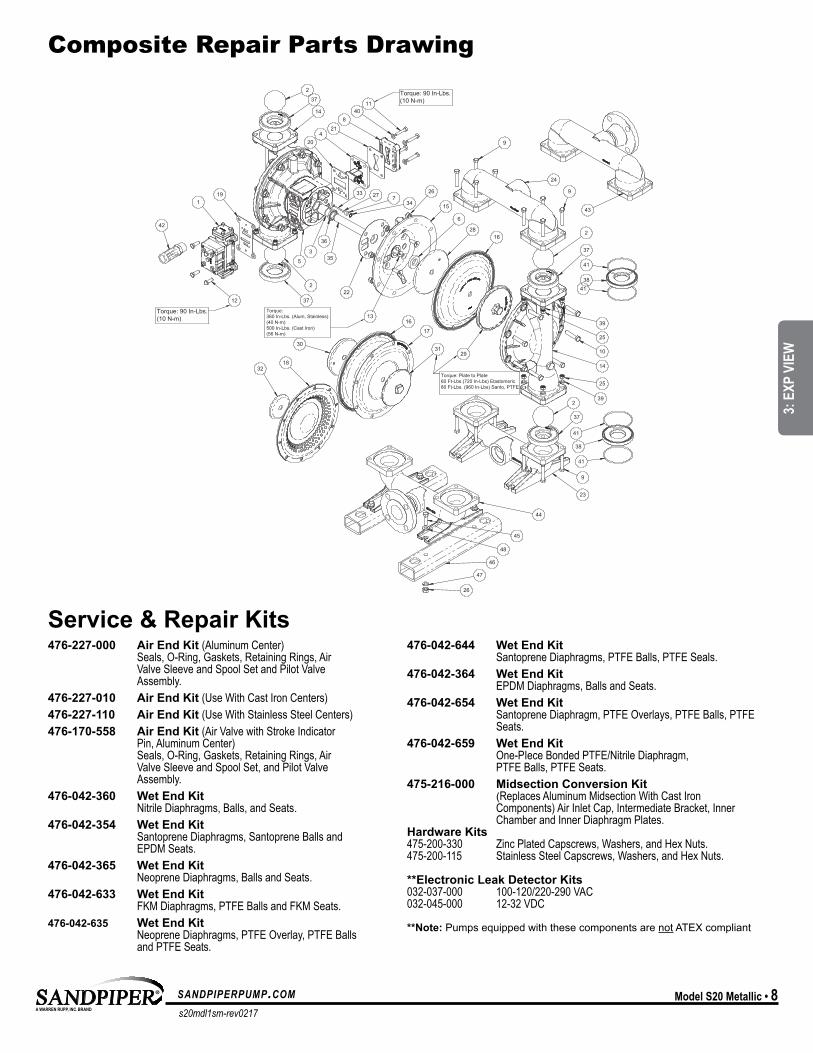
476-227-000 Air End Kit (Aluminum Center) Seals, O-Ring, Gaskets, Retaining Rings, Air Valve Sleeve and Spool Set and Pilot Valve Assembly.476-227-010 Air End Kit (Use With Cast Iron Centers)476-227-110 Air End Kit (Use With Stainless Steel Centers)476-170-558 Air End Kit (Air Valve with Stroke Indicator Pin, Aluminum Center) Seals, O-Ring, Gaskets, Retaining Rings, Air Valve Sleeve and Spool Set, and Pilot Valve Assembly.476-042-360 Wet End Kit Nitrile Diaphragms, Balls, and Seats.476-042-354 Wet End Kit Santoprene Diaphragms, Santoprene Balls and EPDM Seats.476-042-365 Wet End Kit Neoprene Diaphragms, Balls and Seats.476-042-633 Wet End Kit FKM Diaphragms, PTFE Balls and FKM Seats.476-042-635 Wet End Kit Neoprene Diaphragms, PTFE Overlay, PTFE Balls and PTFE Seats.
**Note: Pumps equipped with these components are not ATEX compliant
2
37
14
204
218
4011
191
42
5
3
36
222
37
337
34
35
26
24
9
2
37
9
41
3841
14
25
392
37
41
38
41
9
23
31
17
16
30
1832
15
6
2816
29
13
27
12
43
10
39
25
45
48
46
47
26
44
Torque: 90 In-Lbs.(10 N-m)
Torque:360 In-Lbs. (Alum, Stainless)(40 N-m)500 In-Lbs. (Cast Iron)(56 N-m)
Torque: Plate to Plate60 Ft-Lbs.(720 In-Lbs) Elastomeric80 Ft-Lbs. (960 In-Lbs) Santo, PTFE
ITEM NO. PART NUMBER DESCRIPTION Defaul
t/QTY.
1 031.XXX.XXX AIR VALVE ASSEMBLY (000 OPTION SHOWN) 12 050.XXX.XXX BALL, CHECK 43 070.006.170 BUSHING 24 095.110.XXX PILOT VALVE ASSEMBLY 15 114.024.XXX INTERMEDIATE 16 132.035.360 BUMPER 27 135.034.506 BUSHING, PLUNGER 28 165.116.XXX CAP, AIR INLET (W/ ORIFICE) 19 170.052.XXX CAPSCREW, HEX HD 3/8-16 X 2.25 16
10 170.060.XXX CAPSCREW, HEX HD 7/16-14 X 2.00 1611 170.069.XXX CAPSCREW, HEX HD 5/16-18 X 1.75 412 170.006.XXX CAPSCREW, HEX HD, 3/8-16 X 1.00 513 171.059.XXX CAPSCREW, SOC FH 7/16-14 X 1.25 814 196.167.XXX CHAMBER, OUTER 215 196.168.XXX CHAMBER, INNER 216 286.007.XXX DIAPHRAGM 217 286.020.604 DIAPHRAGM, OVERLAY 218 286.118.000 DIAPHRAGM, SYNTHESIS 219 360.093.360 GASKET, AIR VALVE 120 360.114.360 GASKET, PILOT VALVE 121 360.104.379 GASKET, AIR INLET 122 360.105.360 GASKET, INNER CHAMBER 223 518.145.XXX MANIFOLD, SUCTION 124 518.146.XXX MANIFOLD, DISCHARGE 125 545.005.XXX NUT, HEX 3/8-16 1626 545.007.XXX NUT, HEX 7/16-14 2027 560.001.360 O-RING 228 612.192.XXX PLATE, INNER DIAPHRAGM 229 612.194.XXX PLATE, OUTER DIAPHRAGM 230 612.195.XXX PLATE, INNER DIAPHRAGM (PTFE) 231 612.XXX.XXX PLATE, OUTER DIAPHRAGM (PTFE) 232 612.214.150 PLATE, INNER DIAPHRAGM (SYNTHESIS) 233 620.020.115 PLUNGER, ACTUATOR 234 675.042.115 RING, RETAINING 235 685.058.120 ROD, DIAPHRAGM 136 720.004.360 SEAL, DIAPHRAGM ROD 237 722.040.XXX SEAT, CHECK BALL (RUBBER) 438 722.040.XXX SEAT, CHECK BALL (METAL) 239 900.005.XXX WASHER, LOCK 3/8" 1640 901.038.XXX WASHER, FLAT 5/16" 441 XXX.XXX.XXX SEAL (METAL SEATS ONLY) 442 530.033.000 MUFFLER (600 OPTION) 143 518.146.XXXW MANIFOLD, DISCHARGE (WELDED FLANGE) 144 518.145.XXXW MANIFOLD, SUCTION (WELDED FLANGE) 145 170.035.330 CAPSCREW, HEX-HD 7/16-14 X 1.50 446 326.052.080 FOOT, MOUNTING 247 900.006.115 WASHER, LOCK, 7/16 448 901.022.330 WASHER, FLAT, 7/16 4
Torque: 90 In-Lbs.(10 N-m)
476-042-644 Wet End Kit Santoprene Diaphragms, PTFE Balls, PTFE Seals. 476-042-364 Wet End Kit EPDM Diaphragms, Balls and Seats.476-042-654 Wet End Kit Santoprene Diaphragm, PTFE Overlays, PTFE Balls, PTFE Seats.476-042-659 Wet End Kit
One-PIece Bonded PTFE/Nitrile Diaphragm, PTFE Balls, PTFE Seats.
475-216-000 Midsection Conversion Kit (Replaces Aluminum Midsection With Cast Iron Components) Air Inlet Cap, Intermediate Bracket, Inner Chamber and Inner Diaphragm Plates.Hardware Kits 475-200-330 Zinc Plated Capscrews, Washers, and Hex Nuts. 475-200-115 Stainless Steel Capscrews, Washers, and Hex Nuts.
**Electronic Leak Detector Kits 032-037-000 100-120/220-290 VAC 032-045-000 12-32 VDC
Composite Repair Parts Drawing
Service & Repair Kits
MODEL SPECIFIC
3: E
XP V
IEW
s20mdl1sm-rev0217
sandpiperpump.com9 • Model S20 Metallic
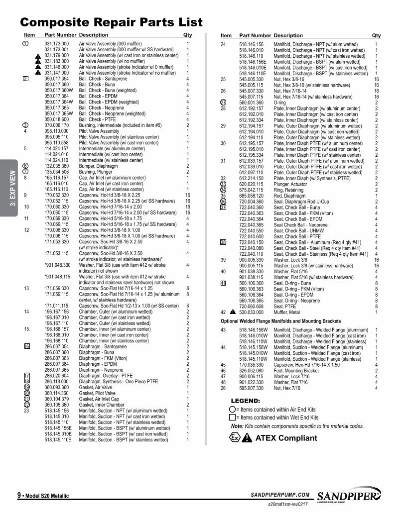
Item Part Number Description Qty24 518.146.156 Manifold, Discharge - NPT (w/ alum wetted) 1 518.146.010 Manifold, Discharge - NPT (w/ cast iron wetted) 1 518.146.110 Manifold, Discharge - NPT (w/ stainless wetted) 1 518.146.156E Manifold, Discharge - BSPT (w/ alum wetted) 1 518.146.010E Manifold, Discharge - BSPT (w/ cast iron wetted) 1 518.146.110E Manifold, Discharge - BSPT (w/ stainless wetted) 125 545.005.330 Nut, Hex 3/8-16 16 545.005.115 Nut, Hex 3/8-16 (w/ stainless hardware) 1626 545.007.330 Nut, Hex 7/16-14 16 545.007.115 Nut, Hex 7/16-14 (w/ stainless hardware) 1627 560.001.360 O-ring 228 612.192.157 Plate, Inner Diaphragm (w/ aluminum center) 2 612.192.010 Plate, Inner Diaphragm (w/ cast iron center) 2 612.192.334 Plate, Inner Diaphragm (w/ stainless center) 229 612.194.157 Plate, Outer Diaphragm (w/ aluminum wetted) 2 612.194.010 Plate, Outer Diaphragm (w/ cast iron wetted) 2 612.194.110 Plate, Outer Diaphragm (w/ stainless wetted) 230 612.195.157 Plate, Inner Diaph PTFE (w/ aluminum center) 2 612.195.010 Plate, Inner Diaph PTFE (w/ cast iron center) 2 612.195.334 Plate, Inner Diaph PTFE (w/ stainless center) 231 612.039.157 Plate, Outer Diaph PTFE (w/ aluminum wetted) 2 612.039.010 Plate, Outer Diaph PTFE (w/ cast iron wetted) 2 612.097.110 Plate, Outer Diaph PTFE (w/ stainless wetted) 232 612.214.150 Plate, Inner Diaph (w/ Synthesis, PTFE) 233 620.020.115 Plunger, Actuator 234 675.042.115 Ring, Retaining 235 685.058.120 Rod, Diaphragm 136 720.004.360 Seal, Diaphragm Rod U-Cup 237 722.040.360 Seat, Check Ball - Buna 4 722.040.363 Seat, Check Ball - FKM (Viton) 4 722.040.364 Seat, Check Ball - EPDM 4 722.040.365 Seat Check Ball - Neoprene 4 722.040.550 Seat, Check Ball - UHMW 4 722.040.600 Seat, Check Ball - PTFE 438 722.040.150 Seat, Check Ball - Aluminum (Req 4 qty #41) 4 722.040.080 Seat, Check Ball - Steel (Req 4 qty Item #41) 4 722.040.110 Seat, Check Ball - Stainless (Req 4 qty Item #41) 439 900.005.330 Washer, Lock 3/8 16 900.005.115 Washer, Lock 3/8 (w/ stainless hardware) 1640 901.038.330 Washer, Flat 5/16 4 901.038.115 Washer, Flat 5/16 (w/ stainless hardware) 441 560.106.360 Seal, O-ring - Buna 8 560.106.363 Seal, O-ring - FKM (Viton) 8 560.106.364 Seal, O-ring - EPDM 8 560.106.365 Seal, O-ring - Neoprene 8 720.060.608 Seal, PTFE 842 530.033.000 Muffler, Metal 1Optional Welded Flange Manifolds and Mounting Brackets43 518.146.156W Manifold, Discharge - Welded Flange (aluminum) 1 518.146.010W Manifold, Discharge - Welded Flange (cast iron) 1 518.146.110W Manifold, Discharge - Welded Flange (stainless) 144 518.145.156W Manifold, Suction - Welded Flange (aluminum) 1 518.145.010W Manifold, Suction - Welded Flange (cast iron) 1 518.145.110W Manifold, Suction - Welded Flange (stainless) 145 170.035.330 Capscrew, Hex-Hd 7/16-14 X 1.50 446 326.052.080 Foot, Mounting Bracket 247 900.006.115 Washer, Lock 7/16 448 901.022.330 Washer, Flat 7/16 426 595.007.330 Nut, Hex 7/16 4
Item Part Number Description Qty1 031.173.000 Air Valve Assembly (000 muffler) 1 031.173.001 Air Valve Assembly (000 muffler w/ SS hardware) 1 031.179.000 Air Valve Assembly (w/ cast iron or stainless center) 1 031.183.000 Air Valve Assembly (w/ no muffler) 1 031.146.000 Air Valve Assembly (stroke Indicator w/ 0 muffler) 1 031.147.000 Air Valve Assembly (stroke Indicator w/ no muffler) 12 050.017.354 Ball, Check - Santoprene 4 050.017.360 Ball, Check - Buna 4 050.017.360W Ball, Check - Buna (weighted) 4 050.017.364 Ball, Check - EPDM 4 050.017.364W Ball, Check - EPDM (weighted) 4 050.017.365 Ball, Check - Neoprene 4 050.017.365W Ball, Check - Neoprene (weighted) 4 050.018.600 Ball, Check - PTFE 43 070.006.170 Bushing, Intermediate (included in item #5) 24 095.110.000 Pilot Valve Assembly 1 095.095.110 Pilot Valve Assembly (w/ stainless center) 1 095.110.558 Pilot Valve Assembly (w/ cast iron center) 15 114.024.157 Intermediate (w/ aluminum center) 1 114.024.010 Intermediate (w/ cast iron center) 1 114.024.110 Intermediate (w/ stainless center) 16 132.035.360 Bumper, Diaphragm 27 135.034.506 Bushing, Plunger 28 165.116.157 Cap, Air Inlet (w/ aluminum center) 1 165.116.010 Cap, Air Inlet (w/ cast iron center) 1 165.116.110 Cap, Air Inlet (w/ stainless center) 19 170.052.330 Capscrew, Hx-Hd 3/8-18 X 2.25 16 170.052.115 Capscrew, Hx-Hd 3/8-18 X 2.25 (w/ SS hardware) 1610 170.060.330 Capscrew, Hx-Hd 7/16-14 x 2.00 16 170.060.115 Capscrew, Hx-Hd 7/16-14 x 2.00 (w/ SS hardware) 1611 170.069.330 Capscrew, Hx-Hd 5/16-18 x 1.75 4 170.069.115 Capscrew, Hx-Hd 5/16-18 x 1.75 (w/ SS hardware) 412 170.006.330 Capscrew, Hx-Hd 3/8-18 X 1.00 4 170.006.115 Capscrew, Hx-Hd 3/8-18 X 1.00 (w/ SS hardware) 4 171.053.330 Capscrew, Soc-Hd 3/8-16 X 2.50 4 (w/ stroke indicator)* 171.053.115 Capscrew, Soc-Hd 3/8-16 X 2.50 4 (w/ stroke indicator, w/ stainless hardware)* *901.048.330 Washer, Flat 3/8 (use with item #12 w/ stroke 4 indicator) not shown *901.048.115 Washer, Flat 3/8 (use with item #12 w/ stroke 4 indicator and stainless steel hardware) not shown 13 171.059.330 Capscrew, Soc-Flat Hd 7/16-14 x 1.25 8 171.059.115 Capscrew, Soc-Flat Hd 7/16-14 x 1.25 (w/ aluminum 8 center, w/ stainless hardware) 171.011.115 Capscrew, Soc-Flat Hd 1/2-13 x 1.00 (w/ SS center) 814 196.167.156 Chamber, Outer (w/ aluminum wetted) 2 196.167.010 Chamber, Outer (w/ cast iron wetted) 2 196.167.110 Chamber, Outer (w/ stainless wetted) 215 196.168.157 Chamber, Inner (w/ aluminum center) 2 196.168.010 Chamber, Inner (w/ cast iron center) 2 196.168.110 Chamber, Inner (w/ stainless center) 216 286.007.354 Diaphragm - Santoprene 2 286.007.360 Diaphragm - Buna 2 286.007.363 Diaphragm - FKM (Viton) 2 286.007.364 Diaphragm - EPDM 2 286.007.365 Diaphragm - Neoprene 217 286.020.604 Diaphragm, Overlay - PTFE 218 286.118.000 Diaphragm, Synthesis - One Piece PTFE 219 360.093.360 Gasket, Air Valve 120 360.114.360 Gasket, Pilot Valve 121 360.104.379 Gasket, Air Inlet Cap 122 360.105.360 Gasket, Inner Chamber 223 518.145.156 Manifold, Suction - NPT (w/ aluminum wetted) 1 518.145.010 Manifold, Suction - NPT (w/ cast iron wetted) 1 518.145.110 Manifold, Suction - NPT (w/ stainless wetted) 1 518.145.156E Manifold, Suction - BSPT (w/ aluminum wetted) 1 518.145.010E Manifold, Suction - BSPT (w/ cast iron wetted) 1 518.145.110E Manifold, Suction - BSPT (w/ stainless wetted) 1
Composite Repair Parts List
ATEX Compliant
LEGEND: = Items contained within Air End Kits = Items contained within Wet End KitsNote: Kits contain components specific to the material codes.
MODEL SPECIFIC
3: E
XP V
IEW
s20mdl1sm-rev0217
sandpiperpump.com Model S20 Metallic • 10
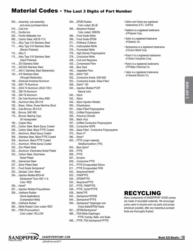
Material Codes - The Last 3 Digits of Part Number
000.....Assembly, sub-assembly; and some purchased items
010.....Cast Iron015.....Ductile Iron020.....Ferritic Malleable Iron080.....Carbon Steel, AISI B-1112110 .....Alloy Type 316 Stainless Steel111 .....Alloy Type 316 Stainless Steel
(Electro Polished)112 .....Alloy C113 .....Alloy Type 316 Stainless Steel
(Hand Polished)114 .....303 Stainless Steel115 .....302/304 Stainless Steel117 .....440-C Stainless Steel (Martensitic)120.....416 Stainless Steel
(Wrought Martensitic)148.....Hardcoat Anodized Aluminum150.....6061-T6 Aluminum152.....2024-T4 Aluminum (2023-T351)155.....356-T6 Aluminum156.....356-T6 Aluminum157.....Die Cast Aluminum Alloy #380158.....Aluminum Alloy SR-319162.....Brass, Yellow, Screw Machine Stock165.....Cast Bronze, 85-5-5-5166.....Bronze, SAE 660170.....Bronze, Bearing Type,
Oil Impregnated180.....Copper Alloy305.....Carbon Steel, Black Epoxy Coated306.....Carbon Steel, Black PTFE Coated307.....Aluminum, Black Epoxy Coated308.....Stainless Steel, Black PTFE Coated309.....Aluminum, Black PTFE Coated313.....Aluminum, White Epoxy Coated330.....Zinc Plated Steel332.....Aluminum, Electroless Nickel Plated333.....Carbon Steel, Electroless
Nickel Plated335.....Galvanized Steel337.....Silver Plated Steel351.....Food Grade Santoprene®
353.....Geolast; Color: Black354.....Injection Molded #203-40
Santoprene® Duro 40D +/-5; Color: RED
356.....Hytrel®357.....Injection Molded Polyurethane358.....Urethane Rubber
(Some Applications) (Compression Mold)
359.....Urethane Rubber360.....Nitrile Rubber Color coded: RED363.....FKM (Fluorocarbon)
Color coded: YELLOW
364.....EPDM Rubber Color coded: BLUE
365.....Neoprene Rubber Color coded: GREEN
366.....Food Grade Nitrile368.....Food Grade EPDM371.....Philthane (Tuftane)374.....Carboxylated Nitrile375.....Fluorinated Nitrile378.....High Density Polypropylene379.....Conductive Nitrile408.....Cork and Neoprene425.....Compressed Fibre426.....Blue Gard440.....Vegetable Fibre500.....Delrin® 500502.....Conductive Acetal, ESD-800503.....Conductive Acetal, Glass-Filled506.....Delrin® 150520.....Injection Molded PVDF
Natural color540.....Nylon542.....Nylon544.....Nylon Injection Molded550.....Polyethylene551.....Glass Filled Polypropylene552.....Unfilled Polypropylene555.....Polyvinyl Chloride556.....Black Vinyl557.....Unfilled Conductive Polypropylene558.....Conductive HDPE559.....Glass Filled - Conductive Polypropylene570.....Rulon II®
580.....Ryton®
600.....PTFE (virgin material) Tetrafluorocarbon (TFE)
603.....Blue Gylon®
604.....PTFE 606.....PTFE 607.....Envelon608.....Conductive PTFE610.....PTFE Encapsulated Silicon611 .....PTFE Encapsulated FKM632.....Neoprene/Hytrel®633.....FKM/PTFE 634.....EPDM/PTFE 635.....Neoprene/PTFE 637.....PTFE, FKM/PTFE 638.....PTFE, Hytrel®/PTFE 639.....Nitrile/TFE643.....Santoprene®/EPDM644.....Santoprene®/PTFE 656 .....Santoprene® Diaphragm and
Check Balls/EPDM Seats661.....EPDM/Santoprene®
666.....FDA Nitrile Diaphragm, PTFE Overlay, Balls, and Seals
668.....PTFE, FDA Santoprene®/PTFE
• Delrin and Hytrel are registered tradenames of E.I. DuPont.
• Nylatron is a registered tradename of Polymer Corp.
• Gylon is a registered tradename of Garlock, Inc.
• Santoprene is a registered tradename of Exxon Mobil Corp.
• Rulon II is a registered tradename of Dixion Industries Corp.
• Ryton is a registered tradename of Phillips Chemical Co.
• Valox is a registered tradename of General Electric Co.
RECYCLING Many components of SANDPIPER® AODD pumps are made of recyclable materials. We encourage pump users to recycle worn out parts and pumps whenever possible, after any hazardous pumped fluids are thoroughly flushed.
UNIVERSAL ALL SP
3: E
XP V
IEW
s20mdl1sm-rev0217
sandpiperpump.com11 • Model S20 Metallic
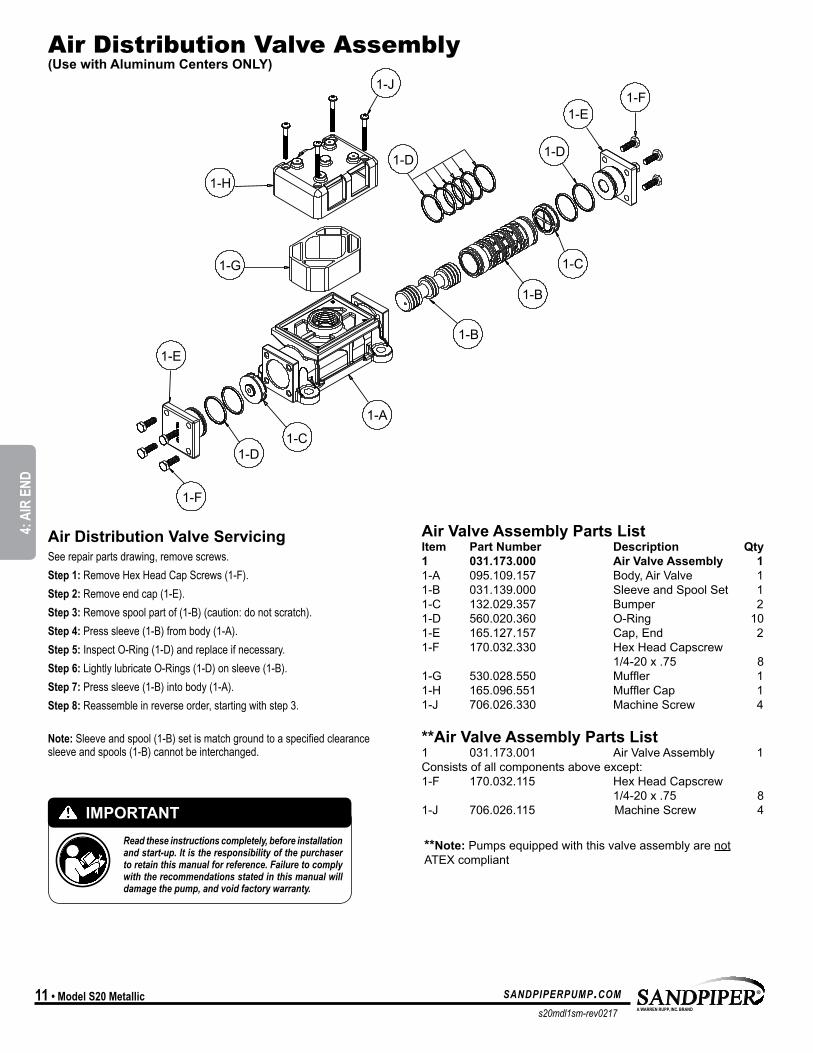
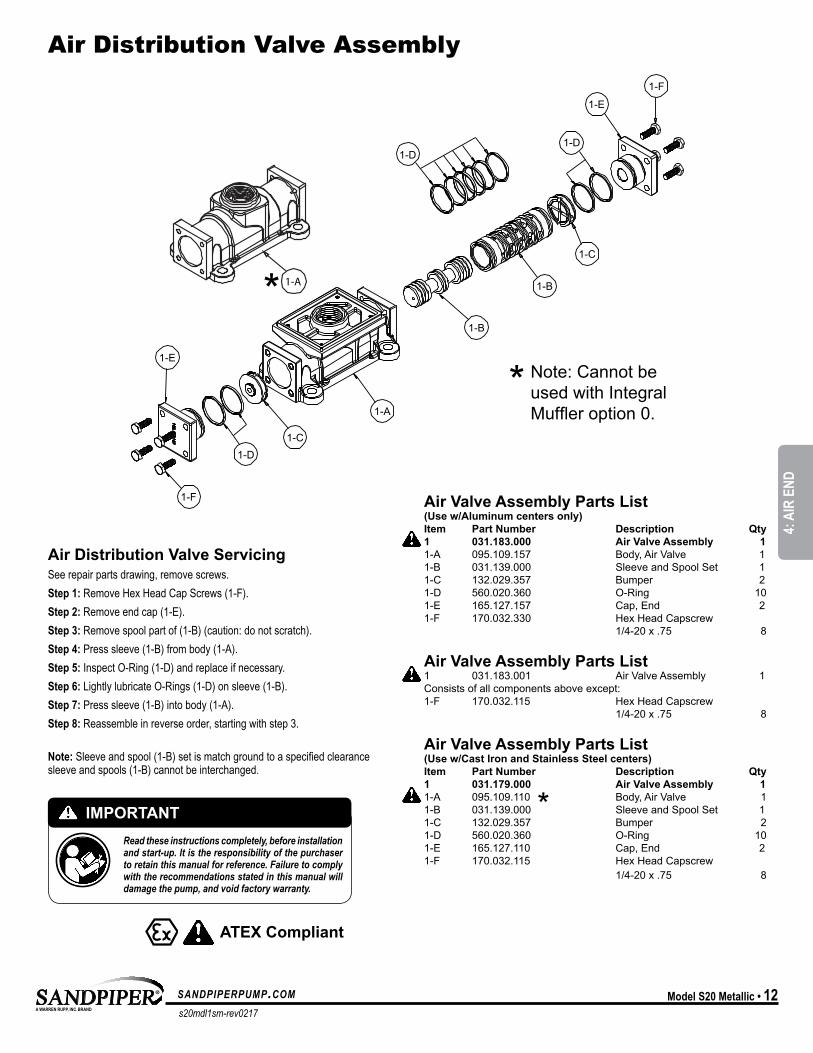
Air Distribution Valve Assembly (Use with Aluminum Centers ONLY)
**Note: Pumps equipped with this valve assembly are not ATEX compliant
Air Valve Assembly Parts List Item Part Number Description Qty1 031.173.000 Air Valve Assembly 11-A 095.109.157 Body, Air Valve 11-B 031.139.000 Sleeve and Spool Set 11-C 132.029.357 Bumper 21-D 560.020.360 O-Ring 101-E 165.127.157 Cap, End 21-F 170.032.330 Hex Head Capscrew 1/4-20 x .75 81-G 530.028.550 Muffler 11-H 165.096.551 MufflerCap 11-J 706.026.330 Machine Screw 4
**Air Valve Assembly Parts List 1 031.173.001 Air Valve Assembly 1Consists of all components above except:1-F 170.032.115 Hex Head Capscrew 1/4-20 x .75 81-J 706.026.115 Machine Screw 4IMPORTANT
Read these instructions completely, before installation and start-up. It is the responsibility of the purchaser to retain this manual for reference. Failure to comply with the recommendations stated in this manual will damage the pump, and void factory warranty.
Air Distribution Valve ServicingSee repair parts drawing, remove screws.Step 1: Remove Hex Head Cap Screws (1-F).Step 2: Remove end cap (1-E).Step 3: Remove spool part of (1-B) (caution: do not scratch).Step 4: Press sleeve (1-B) from body (1-A).Step 5: Inspect O-Ring (1-D) and replace if necessary.Step 6: Lightly lubricate O-Rings (1-D) on sleeve (1-B).Step 7: Press sleeve (1-B) into body (1-A).Step 8: Reassemble in reverse order, starting with step 3.
Note: Sleeve and spool (1-B) set is match ground to a specified clearance sleeve and spools (1-B) cannot be interchanged.
MODEL SPECIFIC
4: A
IR E
ND
s20mdl1sm-rev0217
sandpiperpump.com Model S20 Metallic • 12
Air Distribution Valve Assembly
ATEX Compliant
Air Valve Assembly Parts List (Use w/Aluminum centers only) Item Part Number Description Qty1 031.183.000 Air Valve Assembly 11-A 095.109.157 Body, Air Valve 11-B 031.139.000 Sleeve and Spool Set 11-C 132.029.357 Bumper 21-D 560.020.360 O-Ring 101-E 165.127.157 Cap, End 21-F 170.032.330 Hex Head Capscrew 1/4-20 x .75 8
Air Valve Assembly Parts List 1 031.183.001 Air Valve Assembly 1Consists of all components above except:1-F 170.032.115 Hex Head Capscrew 1/4-20 x .75 8
Air Valve Assembly Parts List (Use w/Cast Iron and Stainless Steel centers) Item Part Number Description Qty1 031.179.000 Air Valve Assembly 11-A 095.109.110 Body, Air Valve 11-B 031.139.000 Sleeve and Spool Set 11-C 132.029.357 Bumper 21-D 560.020.360 O-Ring 101-E 165.127.110 Cap, End 21-F 170.032.115 Hex Head Capscrew 1/4-20 x .75 8
*
*
1-A*Note: Cannot be used with Integral Muffleroption0.
IMPORTANTRead these instructions completely, before installation and start-up. It is the responsibility of the purchaser to retain this manual for reference. Failure to comply with the recommendations stated in this manual will damage the pump, and void factory warranty.
Air Distribution Valve ServicingSee repair parts drawing, remove screws.Step 1: Remove Hex Head Cap Screws (1-F).Step 2: Remove end cap (1-E).Step 3: Remove spool part of (1-B) (caution: do not scratch).Step 4: Press sleeve (1-B) from body (1-A).Step 5: Inspect O-Ring (1-D) and replace if necessary.Step 6: Lightly lubricate O-Rings (1-D) on sleeve (1-B).Step 7: Press sleeve (1-B) into body (1-A).Step 8: Reassemble in reverse order, starting with step 3.
Note: Sleeve and spool (1-B) set is match ground to a specified clearance sleeve and spools (1-B) cannot be interchanged.
4: A
IR E
ND

s20mdl1sm-rev0217
sandpiperpump.com13 • Model S20 Metallic
Air Valve with Stroke Indicator Assembly
1-E
1-A
1-B
1-E
1-J
1-D
1-F
1-G
1-H1-G
1-M
1-C
1-G1-M
1-C
1-K
Note: Stroke Indicator is standard on Spill Containment models
Air Valve Assembly Parts List Item Part Number Description Qty1 031-146-000 Air Valve Assembly 11-A 031-143-000 Sleeve and Spool Set w/Pins 11-B 095-119-559 Body, Air Valve 11-C 132-039-551 Bumper 21-D 165-096-559 Cap, Muffler 11-E 165-156-147 Cap, End 21-F 530-028-550 Muffler 11-G 560-020-360 O-Ring 81-H 675-068-115 Staple 21-J 710-015-115 Screw, Self-Tapping 41-K 210-008-330 Clip, Safety 11-M 560-029-360 O-Ring 2
For Pumps with PTFE Coated Hardware: 1 031-146-002 Air Valve Assembly 1 1-J 710-015-308 Screw, Self Tapping 4 (includes all other items on 031-146-000 above)
For Pumps with Piped Exhaust:1 031-147-000 Air Valve Assembly 1 (includes all items on 031-146-000 minus 1-D, 1-F, & 1-J)
ATEX Compliant
Air Distribution Valve ServicingSee repair parts drawing, remove screws.Step 1: Remove staple retainer (1-H).Step 2: Remove end cap (1-E), bumper (1-C).Step 3: Remove spool part of (1-A) (caution, do not scratch).Step 4: Press sleeve (1-A) from body (1-B).Step 5: Inspect O-Ring (1-G) and replace if necessary.Step 6: Lightly lubricate O-Rings (1-G) on sleeve (1-A).Step 7: Press sleeve (1-A) into body (1-B). Step 8: Reassemble in reverse order.
Note: Sleeve and spool (1-A) set is match ground to a specified clearance sleeve and spools (1-A) cannot be interchanged.
MODEL SPECIFIC
4: A
IR E
ND
s20mdl1sm-rev0217
sandpiperpump.com Model S20 Metallic • 14
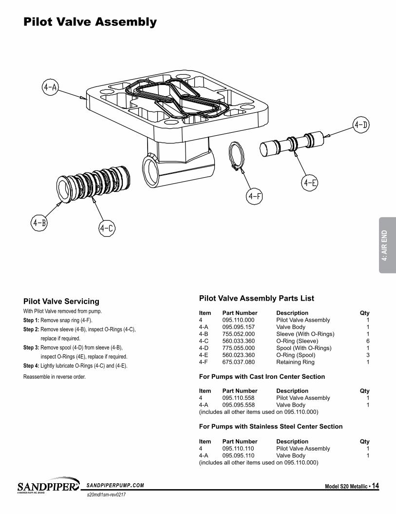
Pilot Valve Assembly
Pilot Valve Assembly Parts List
Item Part Number Description Qty4 095.110.000 Pilot Valve Assembly 14-A 095.095.157 Valve Body 14-B 755.052.000 Sleeve (With O-Rings) 14-C 560.033.360 O-Ring (Sleeve) 64-D 775.055.000 Spool (With O-Rings) 14-E 560.023.360 O-Ring (Spool) 34-F 675.037.080 Retaining Ring 1
For Pumps with Cast Iron Center Section
Item Part Number Description Qty4 095.110.558 Pilot Valve Assembly 14-A 095.095.558 Valve Body 1(includes all other items used on 095.110.000)
For Pumps with Stainless Steel Center Section
Item Part Number Description Qty4 095.110.110 Pilot Valve Assembly 14-A 095.095.110 Valve Body 1(includes all other items used on 095.110.000)
Pilot Valve ServicingWith Pilot Valve removed from pump.Step 1: Remove snap ring (4-F).Step 2: Remove sleeve (4-B), inspect O-Rings (4-C), replace if required.Step 3: Remove spool (4-D) from sleeve (4-B), inspect O-Rings (4E), replace if required.Step 4: Lightly lubricate O-Rings (4-C) and (4-E). Reassemble in reverse order.
MODEL SPECIFIC
4: A
IR E
ND
s20mdl1sm-rev0217
sandpiperpump.com15 • Model S20 Metallic
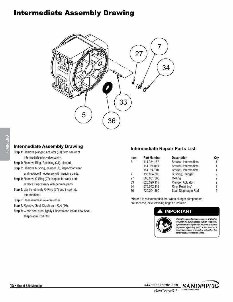
Intermediate Assembly Drawing
Intermediate Repair Parts List
Item Part Number Description Qty5 114.024.157 Bracket, Intermediate 1 114.024.010 Bracket, Intermediate 1 114.024.110 Bracket, Intermediate 17 135.034.506 Bushing, Plunger 227 560.001.360 O-Ring 233 620.020.115 Plunger, Actuator 234 675.042.115 Ring, Retaining* 236 720.004.360 Seal, Diaphragm Rod 2
*Note: It is recommended that when plunger components are serviced, new retaining rings be installed.
Intermediate Assembly DrawingStep 1: Remove plunger, actuator (33) from center of intermediate pilot valve cavity.Step 2: Remove Ring, Retaining (34), discard.Step 3: Remove bushing, plunger (7), inspect for wear and replace if necessary with genuine parts.Step 4: Remove O-Ring (27), inspect for wear and replace if necessary with genuine parts.Step 5: Lightly lubricate O-Ring (27) and insert into intermediate.Step 6: Reassemble in reverse order.Step 7: Remove Seal, Diaphragm Rod (36).Step 8: Clean seal area, lightly lubricate and install new Seal, Diaphragm Rod (36).
IMPORTANTWhen the pumped product source is at a higher level than the pump (flooded suction condition), pipe the exhaust higher than the product source to prevent siphoning spills. In the event of a diaphragm failure a complete rebuild of the center section is recommended.
36
33
5
34
727
37
28
28 14
16
628
17
18
33
15
11 41
27
27
41 11
15
41
27
27
41
31
1428
37
28
16
630
17
Torque: Plate to Plate960 in. lbs.
Torque: Plate to Plate720 in. lbs.960 in. lbs. Santoprene
MODEL SPECIFIC
4: A
IR E
ND
s20mdl1sm-rev0217
sandpiperpump.com Model S20 Metallic • 16
Intermediate Repair Parts List
Item Part Number Description Qty5 114.024.157 Bracket, Intermediate 1 114.024.010 Bracket, Intermediate 1 114.024.110 Bracket, Intermediate 17 135.034.506 Bushing, Plunger 227 560.001.360 O-Ring 233 620.020.115 Plunger, Actuator 234 675.042.115 Ring, Retaining* 236 720.004.360 Seal, Diaphragm Rod 2
*Note: It is recommended that when plunger components are serviced, new retaining rings be installed.
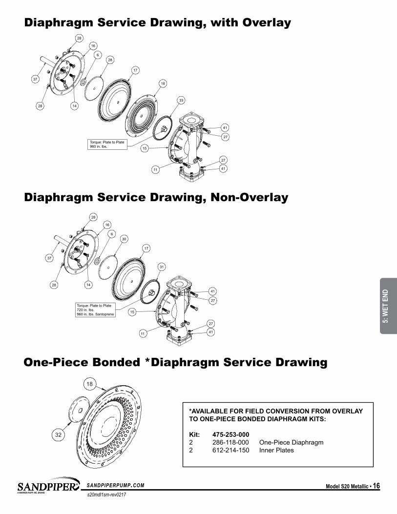
Diaphragm Service Drawing, Non-Overlay
Diaphragm Service Drawing, with Overlay
*AVAILABLE FOR FIELD CONVERSION FROM OVERLAY TO ONE-PIECE BONDED DIAPHRAGM KITS:
Kit: 475-253-0002 286-118-000 One-Piece Diaphragm 2 612-214-150 Inner Plates
One-Piece Bonded *Diaphragm Service Drawing
37
28
28 14
16
628
17
18
33
15
11 41
27
27
41 11
15
41
27
27
41
31
1428
37
28
16
630
17
Torque: Plate to Plate960 in. lbs.
Torque: Plate to Plate720 in. lbs.960 in. lbs. Santoprene
37
28
28 14
16
628
17
18
33
15
11 41
27
27
41 11
15
41
27
27
41
31
1428
37
28
16
630
17
Torque: Plate to Plate960 in. lbs.
Torque: Plate to Plate720 in. lbs.960 in. lbs. Santoprene
18
32
MODEL SPECIFIC
5: W
ET E
ND
s20mdl1sm-rev0217
sandpiperpump.com17 • Model S20 Metallic
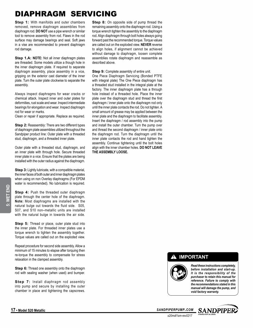
Step 1: With manifolds and outer chambers removed, remove diaphragm assemblies from diaphragm rod. DO NOT use a pipe wrench or similar tool to remove assembly from rod. Flaws in the rod surface may damage bearings and seal. Soft jaws in a vise are recommended to prevent diaphragm rod damage.
Step 1.A: NOTE: Not all inner diaphragm plates are threaded. Some models utilize a though hole in the inner diaphragm plate. If required to separate diaphragm assembly, place assembly in a vice, gripping on the exterior cast diameter of the inner plate. Turn the outer plate clockwise to separate the assembly.
Always inspect diaphragms for wear cracks or chemical attack. Inspect inner and outer plates for deformities, rust scale and wear. Inspect intermediate bearings for elongation and wear. Inspect diaphragm rod for wear or marks. Clean or repair if appropriate. Replace as required.
Step 2: Reassembly: There are two different types of diaphragm plate assemblies utilized throughout the Sandpiper product line: Outer plate with a threaded stud, diaphragm, and a threaded inner plate.
Outer plate with a threaded stud, diaphragm, and an inner plate with through hole. Secure threaded inner plate in a vice. Ensure that the plates are being installed with the outer radius against the diaphragm.
Step 3: Lightly lubricate, with a compatible material, the inner faces of both outer and inner diaphragm plates when using on non Overlay diaphragms (For EPDM water is recommended). No lubrication is required.
Step 4: Push the threaded outer diaphragm plate through the center hole of the diaphragm. Note: Most diaphragms are installed with the natural bulge out towards the fluid side. S05, S07, and S10 non–metallic units are installed with the natural bulge in towards the air side.
Step 5: Thread or place, outer plate stud into the inner plate. For threaded inner plates use a torque wrench to tighten the assembly together. Torque values are called out on the exploded view.
Repeat procedure for second side assembly. Allow a minimum of 15 minutes to elapse after torquing then re-torque the assembly to compensate for stress relaxation in the clamped assembly. Step 6: Thread one assembly onto the diaphragm rod with sealing washer (when used) and bumper.
Step 7: Instal l diaphragm rod assembly into pump and secure by installing the outer chamber in place and tightening the capscrews.
Step 8: On opposite side of pump thread the remaining assembly onto the diaphragm rod. Using a torque wrench tighten the assembly to the diaphragm rod. Align diaphragm through bolt holes always going forward past the recommended torque. Torque values are called out on the exploded view. NEVER reverse to align holes, if alignment cannot be achieved without damage to diaphragm, loosen complete assemblies rotate diaphragm and reassemble as described above.
Step 9: Complete assembly of entire unit.One Piece Diaphragm Servicing (Bonded PTFE with integral plate) The One Piece diaphragm has a threaded stud installed in the integral plate at the factory. The inner diaphragm plate has a through hole instead of a threaded hole. Place the inner plate over the diaphragm stud and thread the first diaphragm / inner plate onto the diaphragm rod only until the inner plate contacts the rod. Do not tighten. A small amount of grease may be applied between the inner plate and the diaphragm to facilitate assembly. Insert the diaphragm / rod assembly into the pump and install the outer chamber. Turn the pump over and thread the second diaphragm / inner plate onto the diaphragm rod. Turn the diaphragm until the inner plate contacts the rod and hand tighten the assembly. Continue tightening until the bolt holes align with the inner chamber holes. DO NOT LEAVE THE ASSEMBLY LOOSE.
DIAPHRAGM SERVICING
IMPORTANTRead these instructions completely, before installation and start-up. It is the responsibility of the purchaser to retain this manual for reference. Failure to comply with the recommendations stated in this manual will damage the pump, and void factory warranty.
UNIVERSAL ALL SP
5: W
ET E
ND
s20mdl1sm-rev0217
sandpiperpump.com Model S20 Metallic • 18
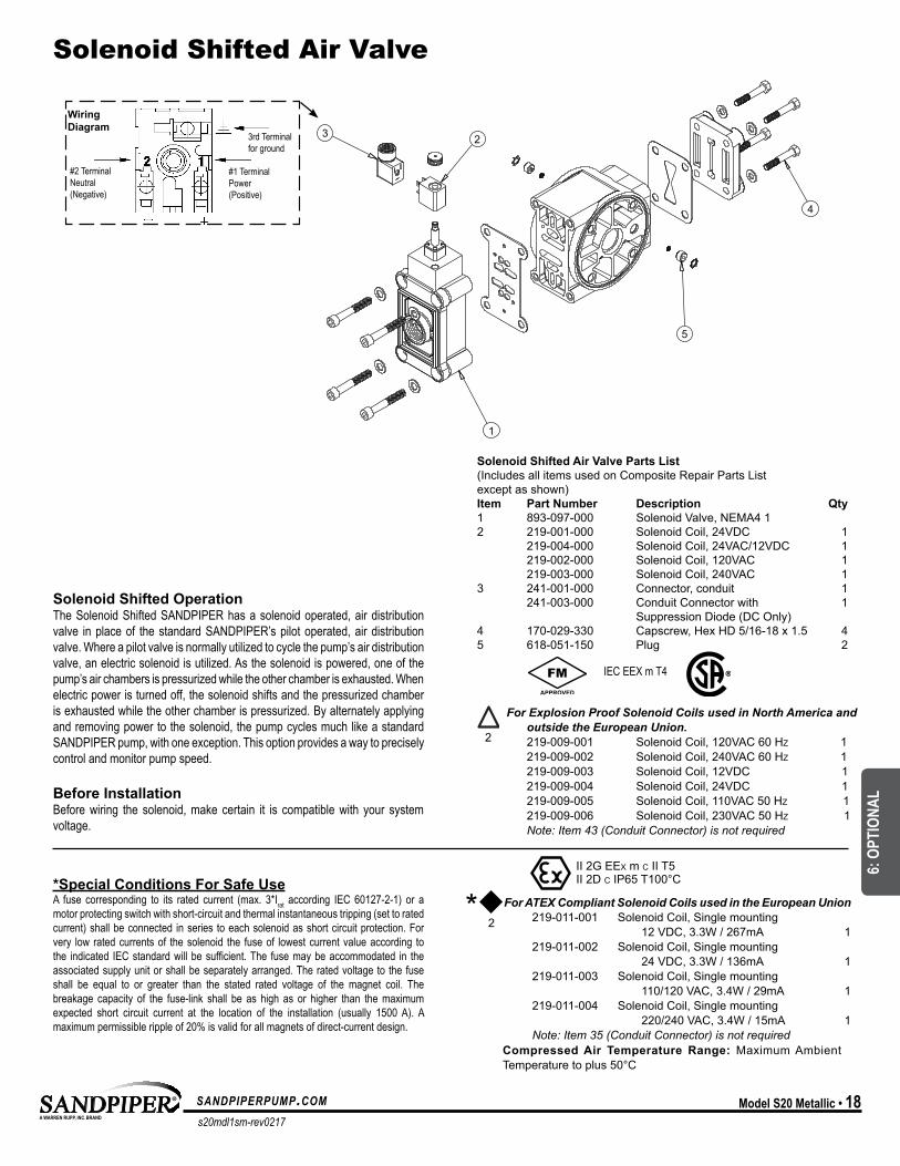
Solenoid Shifted Air Valve
3 2
4
5
1
#2 Terminal Neutral (Negative)
#1 Terminal Power (Positive)
3rd Terminal for ground
Wiring Diagram
Solenoid Shifted Air Valve Parts List(Includes all items used on Composite Repair Parts List except as shown)Item Part Number Description Qty1 893-097-000 Solenoid Valve, NEMA4 1 2 219-001-000 Solenoid Coil, 24VDC 1 219-004-000 Solenoid Coil, 24VAC/12VDC 1 219-002-000 Solenoid Coil, 120VAC 1 219-003-000 Solenoid Coil, 240VAC 13 241-001-000 Connector, conduit 1 241-003-000 Conduit Connector with 1 Suppression Diode (DC Only)4 170-029-330 Capscrew, Hex HD 5/16-18 x 1.5 45 618-051-150 Plug 2
*Special Conditions For Safe UseA fuse corresponding to its rated current (max. 3*Irat according IEC 60127-2-1) or a motor protecting switch with short-circuit and thermal instantaneous tripping (set to rated current) shall be connected in series to each solenoid as short circuit protection. For very low rated currents of the solenoid the fuse of lowest current value according to the indicated IEC standard will be sufficient. The fuse may be accommodated in the associated supply unit or shall be separately arranged. The rated voltage to the fuse shall be equal to or greater than the stated rated voltage of the magnet coil. The breakage capacity of the fuse-link shall be as high as or higher than the maximum expected short circuit current at the location of the installation (usually 1500 A). A maximum permissible ripple of 20% is valid for all magnets of direct-current design.
IEC EEX m T4
For Explosion Proof Solenoid Coils used in North America and outside the European Union. 219-009-001 Solenoid Coil, 120VAC 60 Hz 1 219-009-002 Solenoid Coil, 240VAC 60 Hz 1 219-009-003 Solenoid Coil, 12VDC 1 219-009-004 Solenoid Coil, 24VDC 1 219-009-005 Solenoid Coil, 110VAC 50 Hz 1 219-009-006 Solenoid Coil, 230VAC 50 Hz 1 Note: Item 43 (Conduit Connector) is not required
II 2G EEx m c T5II 2D c IP65 T100°C
For ATEX Compliant Solenoid Coils used in the European Union 219-011-001 Solenoid Coil, Single mounting 12 VDC, 3.3W / 267mA 1 219-011-002 Solenoid Coil, Single mounting 24 VDC, 3.3W / 136mA 1 219-011-003 Solenoid Coil, Single mounting 110/120 VAC, 3.4W / 29mA 1 219-011-004 Solenoid Coil, Single mounting 220/240 VAC, 3.4W / 15mA 1 Note: Item 35 (Conduit Connector) is not required
*II 2G EEx m c II T5II 2D c IP65 T100°c
Compressed Air Temperature Range: Maximum Ambient Temperature to plus 50°C
Solenoid Shifted OperationThe Solenoid Shifted SANDPIPER has a solenoid operated, air distribution valve in place of the standard SANDPIPER’s pilot operated, air distribution valve. Where a pilot valve is normally utilized to cycle the pump’s air distribution valve, an electric solenoid is utilized. As the solenoid is powered, one of the pump’s air chambers is pressurized while the other chamber is exhausted. When electric power is turned off, the solenoid shifts and the pressurized chamber is exhausted while the other chamber is pressurized. By alternately applying and removing power to the solenoid, the pump cycles much like a standard SANDPIPER pump, with one exception. This option provides a way to precisely control and monitor pump speed.
Before InstallationBefore wiring the solenoid, make certain it is compatible with your system voltage.
2
2
MODEL SPECIFIC
6: O
PTIO
NAL
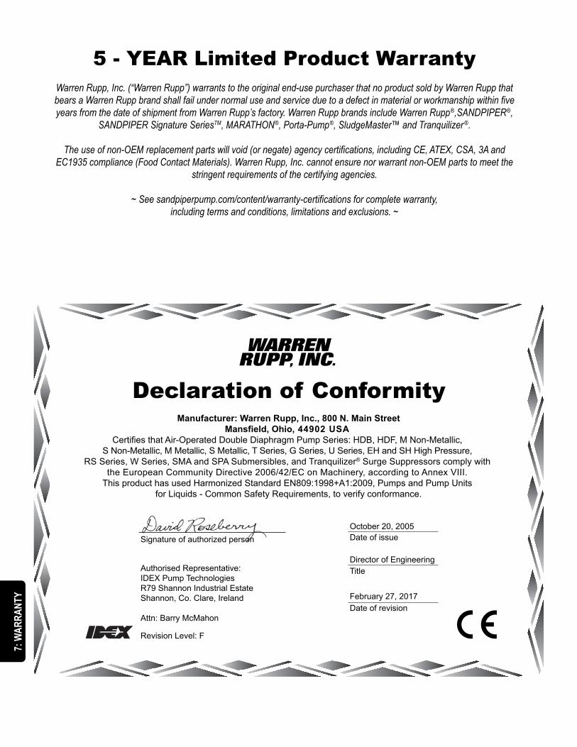
Declaration of Conformity
Signature of authorized person Date of issue
Authorised Representative:IDEX Pump Technologies R79 Shannon Industrial EstateShannon, Co. Clare, Ireland
Attn: Barry McMahon
Revision Level: F
TitleDirector of Engineering
October 20, 2005
Date of revisionFebruary 27, 2017
Manufacturer: Warren Rupp, Inc., 800 N. Main StreetMansfield, Ohio, 44902 USA
Certifies that Air-Operated Double Diaphragm Pump Series: HDB, HDF, M Non-Metallic, S Non-Metallic, M Metallic, S Metallic, T Series, G Series, U Series, EH and SH High Pressure,
RS Series, W Series, SMA and SPA Submersibles, and Tranquilizer® Surge Suppressors comply with the European Community Directive 2006/42/EC on Machinery, according to Annex VIII.
This product has used Harmonized Standard EN809:1998+A1:2009, Pumps and Pump Units for Liquids - Common Safety Requirements, to verify conformance.
5 - YEAR Limited Product WarrantyWarren Rupp, Inc. (“Warren Rupp”) warrants to the original end-use purchaser that no product sold by Warren Rupp that bears a Warren Rupp brand shall fail under normal use and service due to a defect in material or workmanship within five years from the date of shipment from Warren Rupp’s factory. Warren Rupp brands include Warren Rupp®,SANDPIPER®,
SANDPIPER Signature SeriesTM, MARATHON®, Porta-Pump®, SludgeMaster™ and Tranquilizer ®.
The use of non-OEM replacement parts will void (or negate) agency certifications, including CE, ATEX, CSA, 3A and EC1935 compliance (Food Contact Materials). Warren Rupp, Inc. cannot ensure nor warrant non-OEM parts to meet the
stringent requirements of the certifying agencies.
~ See sandpiperpump.com/content/warranty-certifications for complete warranty, including terms and conditions, limitations and exclusions. ~
UNIVERSAL ALL SP
7: W
ARRA
NTY
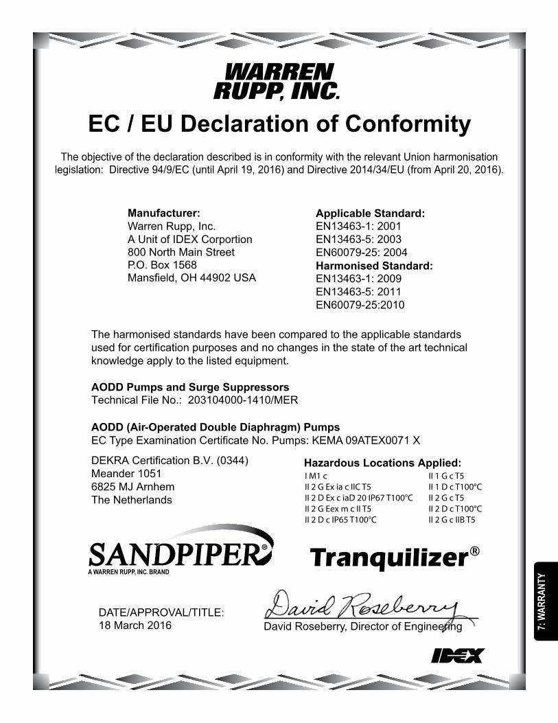
Manufacturer:Warren Rupp, Inc.A Unit of IDEX Corportion800 North Main StreetP.O. Box 1568Mansfield, OH 44902 USA
EC / EU Declaration of ConformityThe objective of the declaration described is in conformity with the relevant Union harmonisation
legislation: Directive 94/9/EC (until April 19, 2016) and Directive 2014/34/EU (from April 20, 2016).
The harmonised standards have been compared to the applicable standards used for certification purposes and no changes in the state of the art technical knowledge apply to the listed equipment.
AODD Pumps and Surge SuppressorsTechnical File No.: 203104000-1410/MER
AODD (Air-Operated Double Diaphragm) PumpsEC Type Examination Certificate No. Pumps: KEMA 09ATEX0071 X
DEKRA Certification B.V. (0344)Meander 10516825 MJ ArnhemThe Netherlands
Applicable Standard:EN13463-1: 2001EN13463-5: 2003EN60079-25: 2004Harmonised Standard:EN13463-1: 2009EN13463-5: 2011EN60079-25:2010
David Roseberry, Director of EngineeringDATE/APPROVAL/TITLE:18 March 2016
Hazardous Locations Applied:I M1 c II 2 G Ex ia c IIC T5II 2 D Ex c iaD 20 IP67 T100°CII 2 G Eex m c II T5II 2 D c IP65 T100°C
II 1 G c T5II 1 D c T100°CII 2 G c T5II 2 D c T100°CII 2 G c IIB T5
7: W
ARRA
NTY