Embed Size (px)
Citation preview
Service, Parts & Maintenance Information Book
NEXT PAGE ENDCONTENTSC
Contents3 Dana Australia Sales & Customer Service Contact List
4 Dana Component Terminology
6 Drive Pinion and Ring Gear Identification
7 Drive Axle Identification Tag Location and Model Identifier Drive
8 Current Dana Axle Models, Drive Axle Nomenclature and Identification
9 Dana Axle Shafts
10 Steer Axle Model Identification and Nomenclature
11 Reading the J300P catalogue (Driveshaft 104)
12 Driveshaft Component Part Number Structure
13 Serrated Bolts 10 Series
14 Measuring UJ & Driveline Angles
16 10 Series Driveshaft Components
17 How To Measure A Yoke
19 Self Aligning Centre Bearing Installation
20 End Fitting Inspection and Universal Joint Inspection
21 Slip Assembly Inspection and Centre Bearing Inspection
22 Causes Of Vibration and Vibration Diagnostics flow chart
23 Spicer Driveshaft Lubrication
24 Failure Analysis Guide
26 SVL Universal Joints for Commercial Applications
27 Available Service Tooling
28 Dana Standard Repair Times
START PREVIOUS PAGE NEXT PAGE END Dana Australia Service, Parts & Maintenance Information Book • 2
START PREVIOUS PAGE NEXT PAGE ENDCONTENTSC Dana Australia Service, Parts & Maintenance Information Book • 3
Brad WolstenholmeHead of Sales & Marketing
+61 418 972 143
Commercial Vehicle
Peter VerdeSales Manager – OE
+61 408 136 824
Jock PickfordFleet Manager
+61 408 571 498
Customer Service & Product Support
Aftermarket
Shane Carey Product Support Manager
+61 438 559 385
Jagath Dharmabandu Program Manager - Aftermarket
+61 419 499 436
John RamseySales Manager – Aftermarket
+61 425 777 915
Michael ParkerBusiness Development Manager
+61 418 962 [email protected]
Warren FarrugiaCustomer Service Manager
+61 408 308 995
Dana Australia Sales & Customer Service Contact List
Paul FrenchBusiness Development Manager
+61 408 136 824
Suzanne WestwellSenior Customer Service Coordinator
Vivian CameronSupport Coordinator
1300 00 DANA [email protected]
+61 3 8779 8504 [email protected]
Technical Support
Nicole NoyProduct Support Officer
+61 3 8779 8504 [email protected]
START PREVIOUS PAGE NEXT PAGE ENDCONTENTSC Dana Australia Service, Parts & Maintenance Information Book • 4
Dana Component TerminologyBalancing – A procedure by which the mass distribution of a rotating body is checked, and corrected to insure smooth operation.
Ball Yoke – See Tube Yoke.
Bearing Cross Hole – See Cross Hole.
Bearing Cup Assembly – Consists of a bearing cup with needle rollers generally held in place by a seal guard and bearing seal. Sometimes the assembly includes a thrust washer.
Bearing Cup – A cup-shaped member used as the bearing bore of a bearing cup assembly and for positioning a thrust end of a cross trunnion.
Bearing Retainer – A heavy, formed metal cap used to retain a bearing cup assembly in Quick Disconnect end yoke or flange yoke designs.
Bearing Seal – A flexible member of a bearing cup assembly which prevents the escape of lubricant from or entry of foreign matter into a bearing.
Bearing Strap – Stamped metal strap used to retain a bearing cup assembly in a half-round end yoke or flange yoke design.
Boot – A flexible member which prevents the escape of lubricant from or entry of foreign matter into the slip spline members.
Boot Clamp – A thin adjustable band used to hold the boot in position on the slip spline members.
Boot Seal – See Boot.
Centre Bearing – Consists of a rolling element bearing isolated in rubber and a bracket configuration for attachment to the vehicle frame.
Companion Flange – A fixed flange member that attaches the driveshaft assembly to another drivetrain component.
Coupling Shaft – The coupling member or members of a multiple-piece driveline which includes a centre bearing.
Cross – See Journal Cross.
Cross Hole – A through hole in each lug ear of a yoke used to locate a bearing cup assembly.
Deflector – See Slinger.
Driveline – An assembly of one or more coupling shafts and a driveshaft with provisions for axial movement, which transmits torque and/or rotary motion at a fixed or varying angular relationship from one drivetrain component to another.
Driveshaft – An assembly of one or two universal joints connected to a tubular shaft member which accomodates axial movement.
Driveshaft Length (Centre Line to Centre Line or CL to CL) – The distance between the outermost universal joint centres on a driveshaft. On driveshafts with variable length centres, it is usually measured in the compressed or installed lengths.
Ear – One of two projecting parts of a yoke symmetrically located with respect to the yoke’s rotational axis.
End Fitting – An end yoke or companion flange (including S.A.E>, DIN and T-Type styles) that attaches a driveshaft to another drivetrain component.
Flange Yoke – A full-round or Quick Disconnect style yoke which attaches a driveshaft to a companion flange.
Glidecote – The blue, nylon, wear-resistant coating on Spicer yoke shafts and tube shafts.
Grease Zerk Fitting – The fitting on the shoulder or centre of a journal cross or on a relubable slip spline that allows for lubrication.
Inboard Yokes – Yokes that make up the ends of a driveshaft or coupling shaft assembly, i.e. tube yokes, slip yokes, yoke shafts, and centre bearing end yokes.
Installation Height Tools – Round, hard plastic disk that are supplied with all Spicer Life Series replacement universal joint kits to ensure proper bearing cup assembly installation specifications.
Journal Cross – The core component of a universal joint which is an intermediate drive member with four equally spaced trunnions in the same plane.
Lug Ear – See Ear.
Midship Shaft – A machined element consisting of spline teeth, a pilot for a centre bearing and a piloting hub that attaches to tube of a coupling shaft assembly.
Needle Rollers – One of the rolling elements of a bearing cup assembly.
Outboard Components – Yokes that are not a part of a driveshaft, i.e. transmission, axle, transfer case end yokes and/or companion flanges.
Phase Angle – The relative rotational position of each yoke on a driveshaft or driveline.
Pressure Relief Hole – A hold in the welch plug of Spicer slip yokes that allows air to escape from the slip member assembly.
Purge – The act of flushing old grease and contaminants from universal joint kits and slip member assemblies with fresh grease.
Quick Disconnect Cross Hole – A semicircular hole located on the end of each lug ear of some end yoke and flange yoke designs used to locate a bearing cup assembly.
START PREVIOUS PAGE NEXT PAGE ENDCONTENTSC Dana Australia Service, Parts & Maintenance Information Book • 5
Retaining Ring – See Snap Ring.
Retaining Ring Groove – See Snap Ring Groove.
Seal Can – A metal ‘can’ that permanently seals the slip member on a driveshaft. Usually found on European-style driveshaft assemblies.
Seal Guard – A covering member used to protect a bearing seal on the bearing cup assembly.
Serrated Flange – See T-Flange.
Shaft Length – Distance between the outermost universal joint centre to joint centre.
Shaft Support Bearing – See Centre Bearing.
Slinger – A stamped metal or non-metal ring which prevents the entry of foreign matter into a centre bearing, transmission, axle or transfer case.
Slip – The total permissible length of axial travel.
Slip Yoke – A yoke which accomodates axial movement.
Slip Yoke Plug – See Welch Plug.
Slip Yoke Seal – Pop-on or threaded ring that contains a seal that protects the slip member assembly from environmental contaminants and retains lubricant.
Snap Ring – A removable member used as a shoulder to retain and position a bearing cup assembly in a yoke cross hole.
Snap Ring Groove – A groove used to locate a snap ring.
Spline – A machined element consisting of integral keys (spline teeth) or keyways (spaces) equally spaced around a circle or portion thereof.
Spline Sleeve – A tubular-type, machined element consisting of internal splines which is attached to a tube or tube yoke in a driveshaft assembly.
Spring Tab – A patented stamped metal plate that takes the place of a bearing plate and acts as a structural member by reducing looseness in a universal joint kit. Found only on Spicer Life Series driveshaft assemblies.
Stub Shaft – See Tube Shaft.
Tang – A nib of metal found on Quick Disconnect end yoke and/or flange yoke style cross holes, used to locate a bearing cup assembly.
T-Flange – A companion flange and flange yoke design which has a serrated flange face. Found most often in European applications.
T-Type Flange – See T-Flange.
Thrust Washer – A washer found in the bottom of a bearing cup assembly that reduces needle roller friction, bearing heat and guards against end galling on the journal cross trunnions.
Tubing – See Tube.
Tube O.D. (outside diameter) – The outside diameter of a tube.
Tube Yoke – An inboard yoke with a piloting hub for attachment to a tube or spline sleeve.
Tube Shaft – A machined element consisting of spline teeth and a poloting hub that attaches to the tube of a driveshaft assembly.
Trunnion(s) – Any of the four projecting journals of a cross.
START PREVIOUS PAGE NEXT PAGE ENDCONTENTSC Dana Australia Service, Parts & Maintenance Information Book • 6
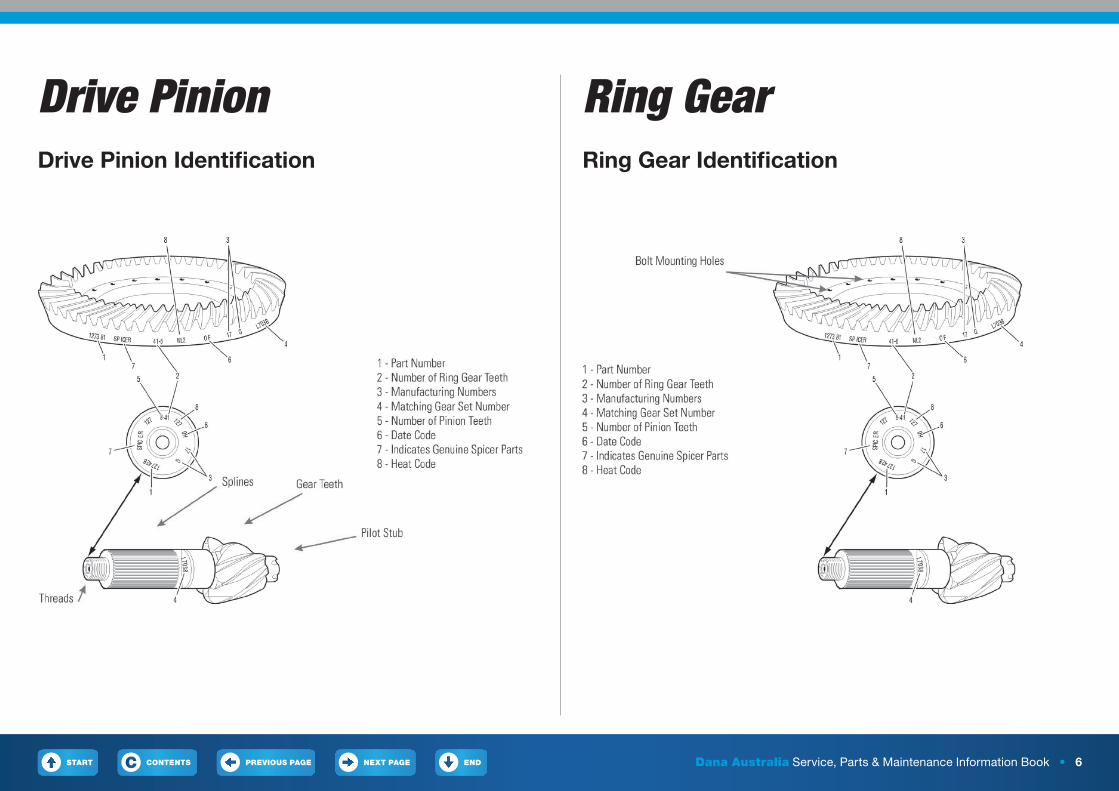
Drive Pinion Ring GearDrive Pinion Identification Ring Gear Identification
START PREVIOUS PAGE NEXT PAGE ENDCONTENTSC Dana Australia Service, Parts & Maintenance Information Book • 7
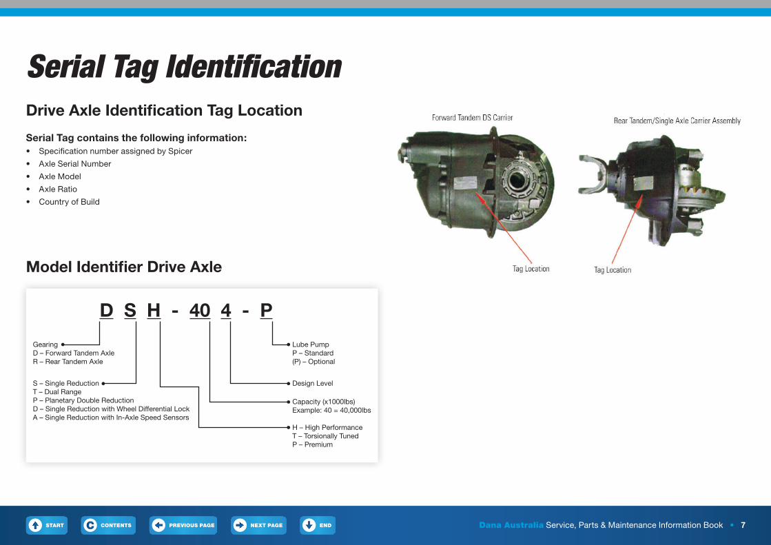
Serial Tag IdentificationDrive Axle Identification Tag Location
Serial Tag contains the following information:• Specification number assigned by Spicer
• Axle Serial Number
• Axle Model
• Axle Ratio
• Country of Build
Model Identifier Drive Axle
GearingD – Forward Tandem AxleR – Rear Tandem Axle
D S H - 40 4 - PLube PumpP – Standard(P) – Optional
S – Single ReductionT – Dual RangeP – Planetary Double ReductionD – Single Reduction with Wheel Differential LockA – Single Reduction with In-Axle Speed Sensors
Design Level
Capacity (x1000lbs)Example: 40 = 40,000lbs
H – High PerformanceT – Torsionally TunedP – Premium
START PREVIOUS PAGE NEXT PAGE ENDCONTENTSC Dana Australia Service, Parts & Maintenance Information Book • 8
Current Dana Axle ModelsTandem Axles• DSH40
• D46-170 & D50-170
• D52-190
• D52-590
Tri Drive Axles• T78-190
• T78-590
Steer Axles• E1322I & E1462I
• D2000F
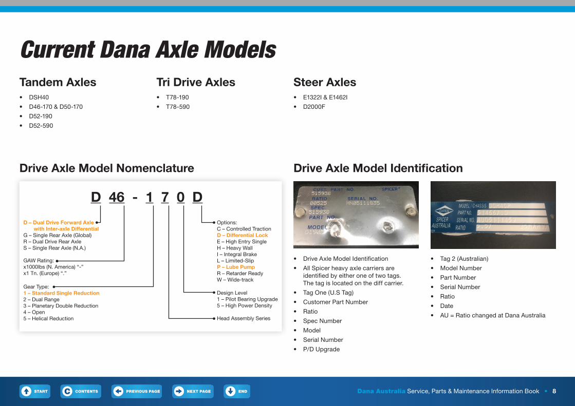
Drive Axle Model Identification
• Tag 2 (Australian)
• Model Number
• Part Number
• Serial Number
• Ratio
• Date
• AU = Ratio changed at Dana Australia
• Drive Axle Model Identification
• All Spicer heavy axle carriers are identified by either one of two tags. The tag is located on the diff carrier.
• Tag One (U.S Tag)
• Customer Part Number
• Ratio
• Spec Number
• Model
• Serial Number
• P/D Upgrade
Drive Axle Model Nomenclature
D – Dual Drive Forward Axle with Inter-axle DifferentialG – Single Rear Axle (Global)R – Dual Drive Rear AxleS – Single Rear Axle (N.A.)
GAW Rating:x1000lbs (N. America) “-”x1 Tn. (Europe) “.”
D 46 - 1 7 D0
Head Assembly Series
Design Level1 – Pilot Bearing Upgrade5 – High Power Density
Options:C – Controlled TractionD – Differential LockE – High Entry SingleH – Heavy WallI – Integral BrakeL – Limited-SlipP – Lube PumpR – Retarder ReadyW – Wide-track
Gear Type:1 – Standard Single Reduction2 – Dual Range3 – Planetary Double Reduction4 – Open5 – Helical Reduction
START PREVIOUS PAGE NEXT PAGE ENDCONTENTSC Dana Australia Service, Parts & Maintenance Information Book • 9
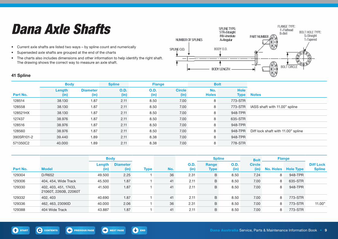
Dana Axle Shafts• Current axle shafts are listed two ways – by spline count and numerically
• Superseded axle shafts are grouped at the end of the charts
• The charts also includes dimensions and other information to help identify the right shaft. The drawing shows the correct way to measure an axle shaft.
41 Spline
Part No.
Body Spline Flange Bolt
NotesLength
(in)Diameter
(in)O.D. (in)
O.D. (in)
Circle (in)
No. Holes
Hole Type
128514 38.130 1.87 2.11 8.50 7.00 8 773-STR
128558 38.130 1.87 2.11 8.50 7.00 8 773-STR IASS shaft with 11.00” spline
128521HX 38.130 1.87 2.11 8.50 7.00 8 948-TPR
127437 38.976 1.87 2.11 8.50 7.00 8 635-STR
128516 38.976 1.87 2.11 8.50 7.00 8 948-TPR
128560 38.976 1.87 2.11 8.50 7.00 8 948-TPR Diff lock shaft with 11.00” spline
390SR101-2 39.440 1.89 2.11 8.38 7.00 8 948-TPR
571350C2 40.000 1.89 2.11 8.38 7.00 8 778-STR
Part No. Model
Body
Type No.O.D. (in)
Spline Bolt Circle
(in)
Flange
Diff Lock Spline
Length (in)
Diameter (in)
Range Type
O.D. (in) No. Holes Hole Type
129304 D/R652 49.500 2.25 1 36 2.31 B 8.50 7.24 8 948-TPR
129306 404, 454, Wide Track 45.500 1.87 1 41 2.11 B 8.50 7.00 8 635-STR
129330 402, 403, 451, 17433, 21060T, 2260B, 22060T
41.500 1.87 1 41 2.11 B 8.50 7.00 8 948-TPR
129332 402, 403 40.690 1.87 1 41 2.11 B 8.50 7.00 8 773-STR
129336 462, 463, 23090D 40.000 2.06 1 36 2.31 B 8.50 7.00 8 773-STR 11.00”
129388 404 Wide Track 43.887 1.87 1 41 2.11 B 8.50 7.00 8 773-STR
START PREVIOUS PAGE NEXT PAGE ENDCONTENTSC Dana Australia Service, Parts & Maintenance Information Book • 10
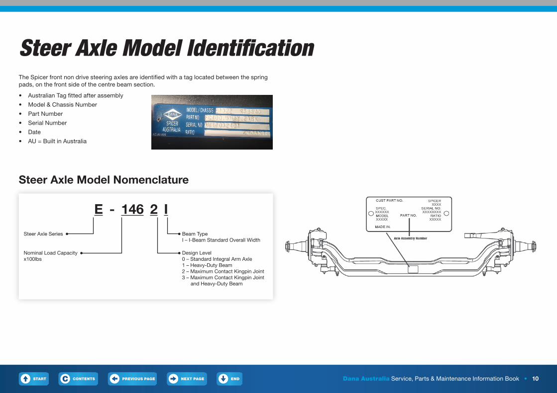
Steer Axle Model IdentificationThe Spicer front non drive steering axles are identified with a tag located between the spring pads, on the front side of the centre beam section.
• Australian Tag fitted after assembly
• Model & Chassis Number
• Part Number
• Serial Number
• Date
• AU = Built in Australia
Steer Axle Model Nomenclature
Steer Axle Series
E - 146 2 IBeam TypeI – I-Beam Standard Overall Width
Nominal Load Capacityx100lbs
Design Level0 – Standard Integral Arm Axle1 – Heavy-Duty Beam2 – Maximum Contact Kingpin Joint3 – Maximum Contact Kingpin Joint and Heavy-Duty Beam
START PREVIOUS PAGE NEXT PAGE ENDCONTENTSC Dana Australia Service, Parts & Maintenance Information Book • 11
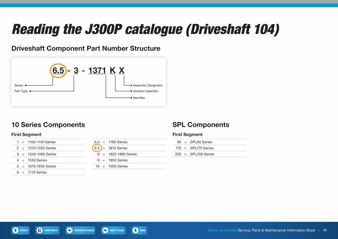
Reading the J300P catalogue (Driveshaft 104)Driveshaft Component Part Number Structure
10 Series ComponentsFirst Segment
1 = 1100-1140 Series
2 = 1210-1330 Series
3 = 1340-1480 Series
4 = 1550 Series
5 = 1610-1650 Series
6 = 1710 Series
6.3 = 1760 Series
6.5 = 1810 Series
8 = 1820-1880 Series
9 = 1950 Series
10 = 1000 Series
SPL ComponentsFirst Segment
90 = SPL90 Series
170 = SPL170 Series
250 = SPL250 Series
Series
6.5 - -3 1371 K XAssembly Designator
Part Type Variation Specifier
Identifier
START PREVIOUS PAGE NEXT PAGE ENDCONTENTSC Dana Australia Service, Parts & Maintenance Information Book • 12
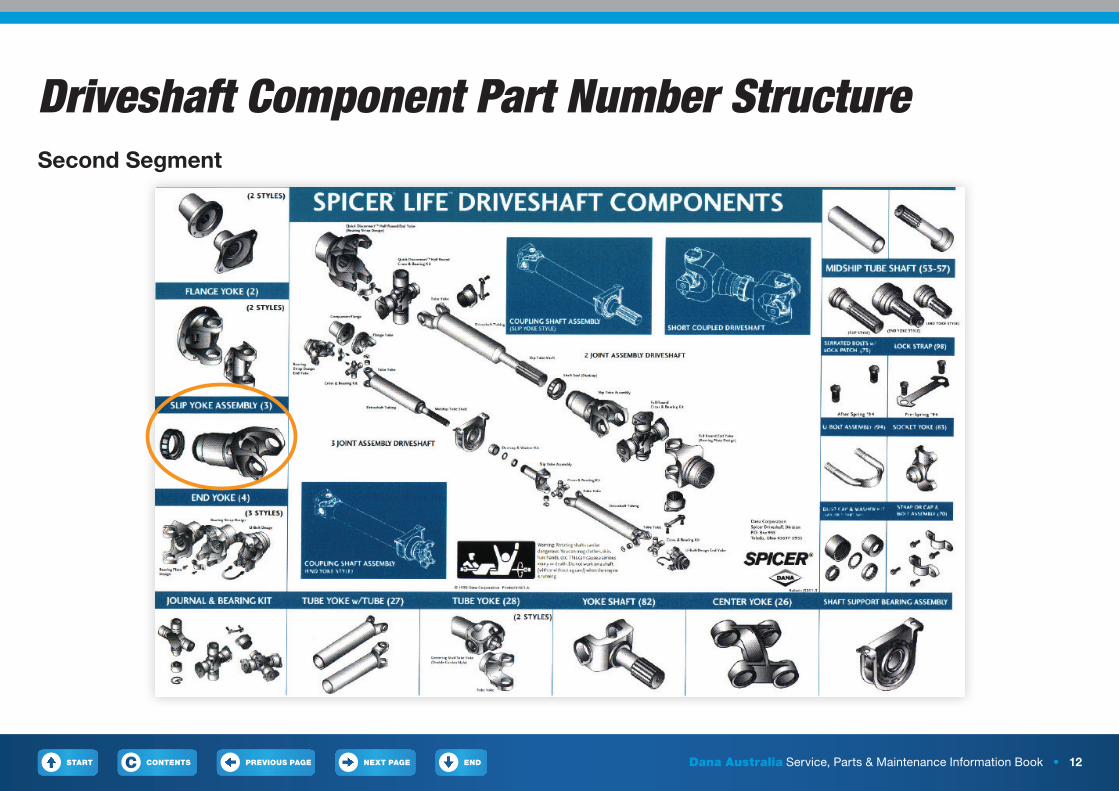
Driveshaft Component Part Number StructureSecond Segment
START PREVIOUS PAGE NEXT PAGE ENDCONTENTSC Dana Australia Service, Parts & Maintenance Information Book • 13
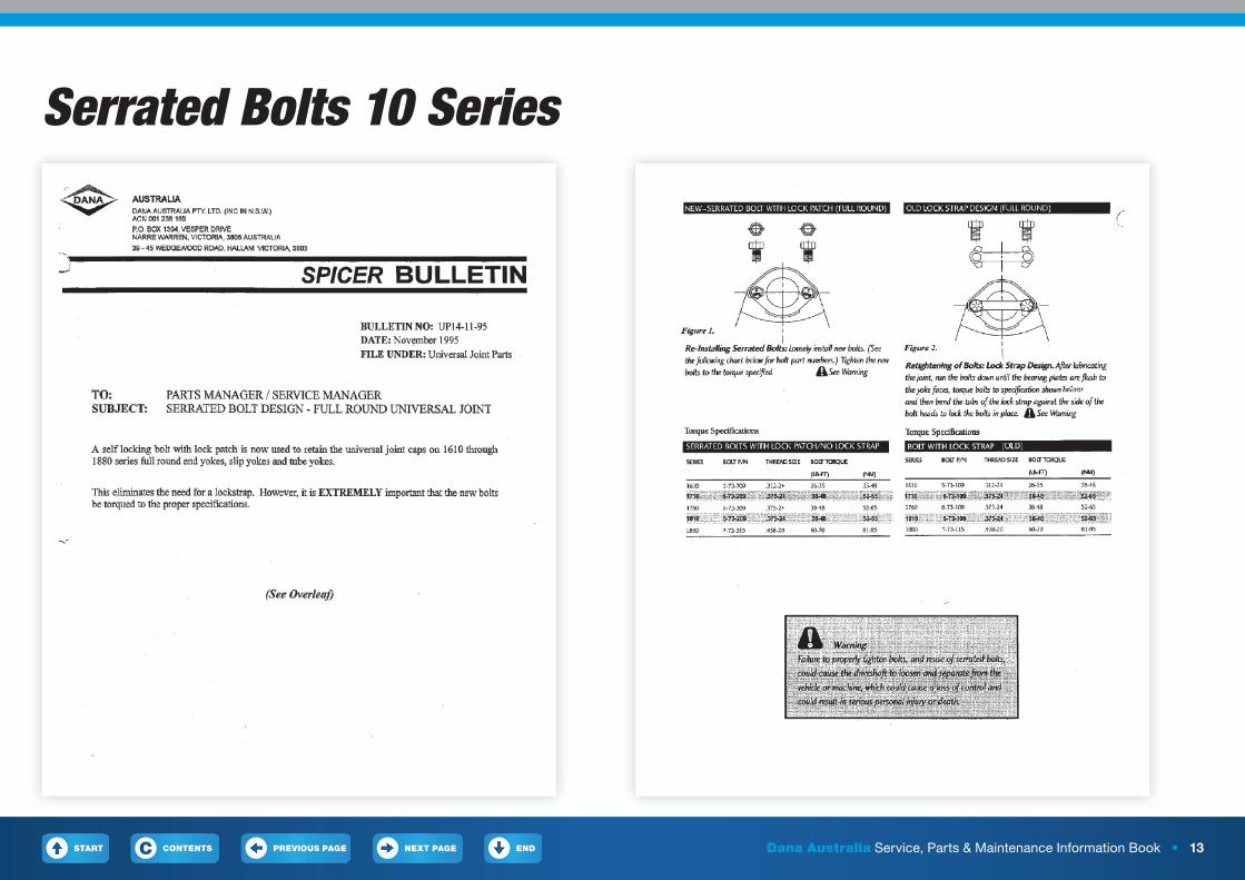
Serrated Bolts 10 Series
START PREVIOUS PAGE NEXT PAGE ENDCONTENTSC Dana Australia Service, Parts & Maintenance Information Book • 14
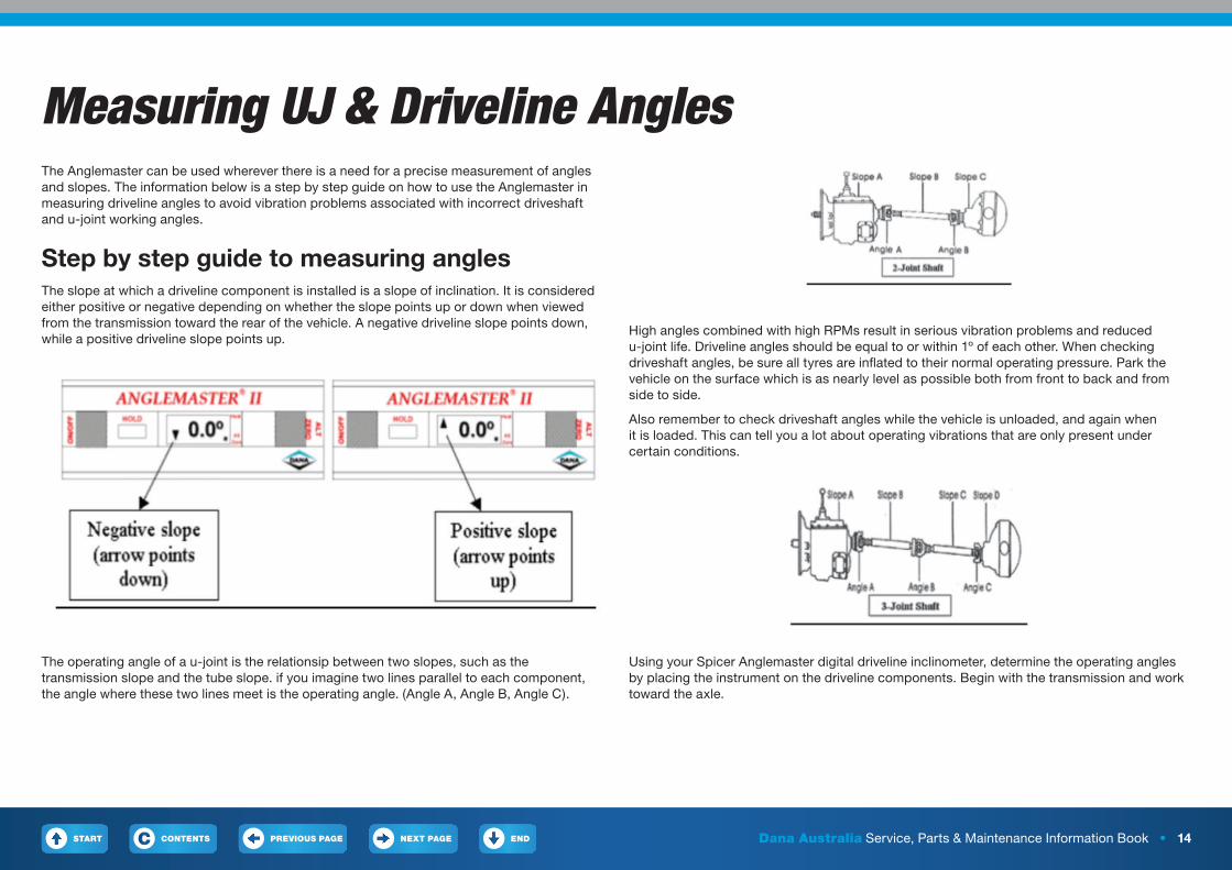
Measuring UJ & Driveline AnglesThe Anglemaster can be used wherever there is a need for a precise measurement of angles and slopes. The information below is a step by step guide on how to use the Anglemaster in measuring driveline angles to avoid vibration problems associated with incorrect driveshaft and u-joint working angles.
Step by step guide to measuring anglesThe slope at which a driveline component is installed is a slope of inclination. It is considered either positive or negative depending on whether the slope points up or down when viewed from the transmission toward the rear of the vehicle. A negative driveline slope points down, while a positive driveline slope points up.
High angles combined with high RPMs result in serious vibration problems and reduced u-joint life. Driveline angles should be equal to or within 1º of each other. When checking driveshaft angles, be sure all tyres are inflated to their normal operating pressure. Park the vehicle on the surface which is as nearly level as possible both from front to back and from side to side.
Also remember to check driveshaft angles while the vehicle is unloaded, and again when it is loaded. This can tell you a lot about operating vibrations that are only present under certain conditions.
Using your Spicer Anglemaster digital driveline inclinometer, determine the operating angles by placing the instrument on the driveline components. Begin with the transmission and work toward the axle.
The operating angle of a u-joint is the relationsip between two slopes, such as the transmission slope and the tube slope. if you imagine two lines parallel to each component, the angle where these two lines meet is the operating angle. (Angle A, Angle B, Angle C).
START PREVIOUS PAGE NEXT PAGE ENDCONTENTSC Dana Australia Service, Parts & Maintenance Information Book • 15
Measuring UJ & Driveline Angles1. Place the unit on the first slope (Slope A) and allow the reading to
stabilise approximately 10 seconds.
2. Push the ‘Alt Zero’ button.
3. The display will read 0.0º and the ‘Alt Zero’ button indicator will flash. The slope you are using will be the new reference.
4. Move the unit to the next adjacent slope (Slope B). The reading obtained is the operating angle of the two slopes (Angle A).
5. To obtain additional operating angles, push the ‘Alt Zero’ button again, and then repeat the above process starting at the second slope (Slope B as the Alternate Zero and measure Slope C to get Angle B).
Note: For maximum universal joint life and to reduce driveline vibration, operating angles should be:
1. Between 1º and 3º; and
2. Equal at either end of a shaft to within 1º
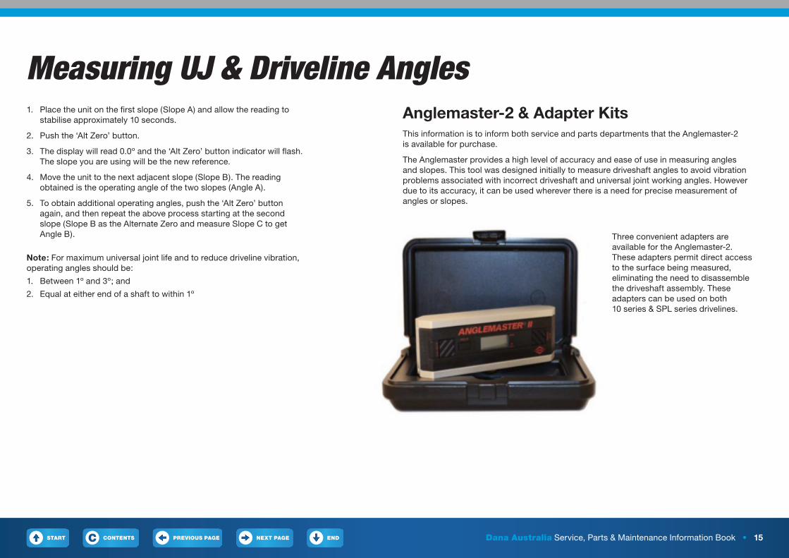
Anglemaster-2 & Adapter KitsThis information is to inform both service and parts departments that the Anglemaster-2 is available for purchase.
The Anglemaster provides a high level of accuracy and ease of use in measuring angles and slopes. This tool was designed initially to measure driveshaft angles to avoid vibration problems associated with incorrect driveshaft and universal joint working angles. However due to its accuracy, it can be used wherever there is a need for precise measurement of angles or slopes.
Three convenient adapters are available for the Anglemaster-2. These adapters permit direct access to the surface being measured, eliminating the need to disassemble the driveshaft assembly. These adapters can be used on both 10 series & SPL series drivelines.
START PREVIOUS PAGE NEXT PAGE ENDCONTENTSC Dana Australia Service, Parts & Maintenance Information Book • 16
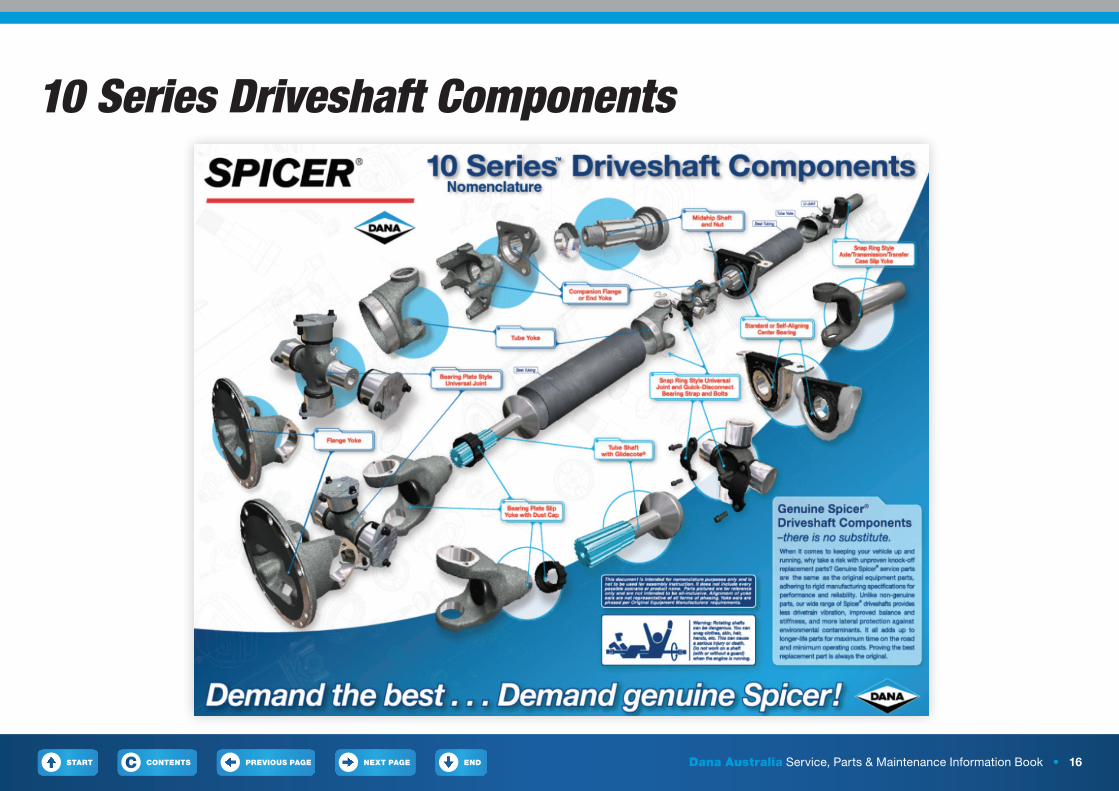
10 Series Driveshaft Components

START PREVIOUS PAGE NEXT PAGE ENDCONTENTSC Dana Australia Service, Parts & Maintenance Information Book • 17
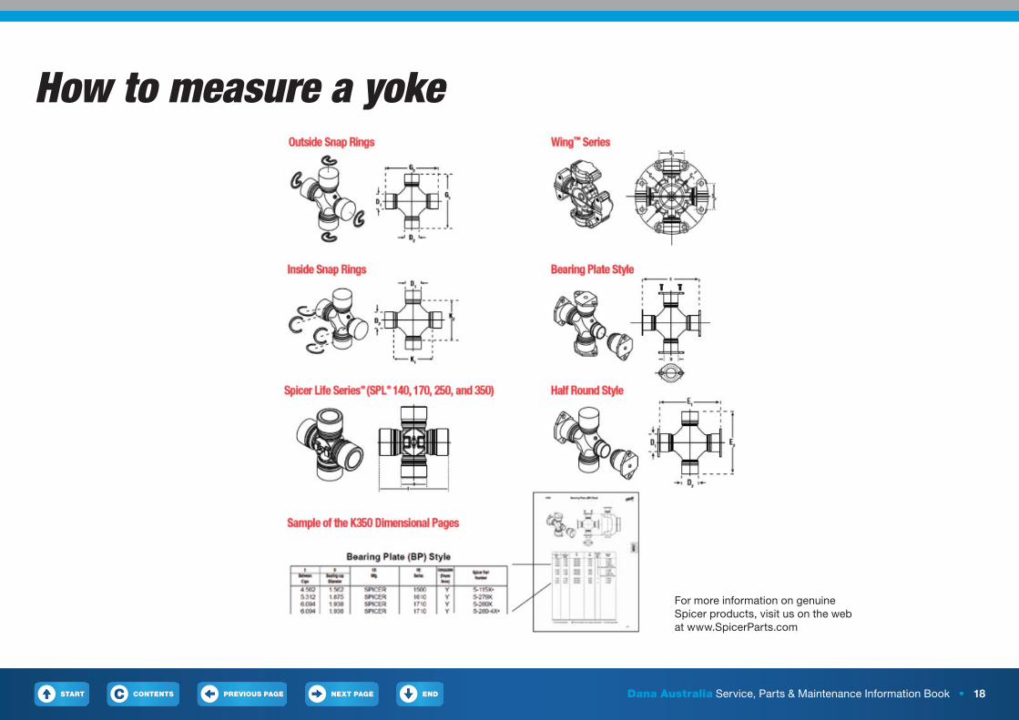
How to measure a yokeThis section will demonstrate how to use the Spicer Yoke Ruler to determine the correct Spicer driveshaft series when all you have is a yoke from a driveshaft.
Note: This ruler will only measure Spicer Series yokes and is not inclusive of all driveshaft series. Refer to chart on the next page for u-joint kit number choices.
• Measure from the outside of the yoke ears
• Read result on opposite ear
• Measure from the inside of the tab
• Read result on opposite tab
• Measure from the inside of the pilot diameter
• Read result on opposite pilot diameter
Full Round Yokes Half Round Yokes Wing Style Yokes
START PREVIOUS PAGE NEXT PAGE ENDCONTENTSC Dana Australia Service, Parts & Maintenance Information Book • 18
How to measure a yoke
For more information on genuine Spicer products, visit us on the web at www.SpicerParts.com
START PREVIOUS PAGE NEXT PAGE ENDCONTENTSC Dana Australia Service, Parts & Maintenance Information Book • 19
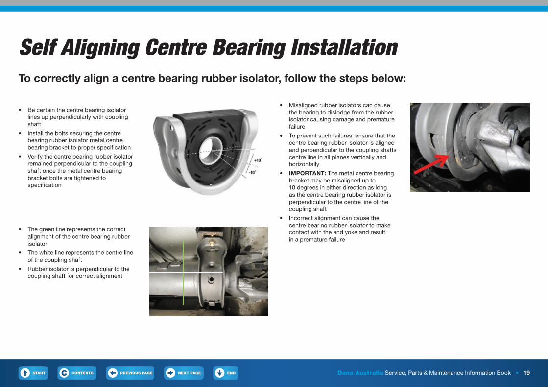
Self Aligning Centre Bearing InstallationTo correctly align a centre bearing rubber isolator, follow the steps below:
• The green line represents the correct alignment of the centre bearing rubber isolator
• The white line represents the centre line of the coupling shaft
• Rubber isolator is perpendicular to the coupling shaft for correct alignment
• Be certain the centre bearing isolator lines up perpendicularly with coupling shaft
• Install the bolts securing the centre bearing rubber isolator metal centre bearing bracket to proper specification
• Verify the centre bearing rubber isolator remained perpendicular to the coupling shaft once the metal centre bearing bracket bolts are tightened to specification
• Misaligned rubber isolators can cause the bearing to dislodge from the rubber isolator causing damage and premature failure
• To prevent such failures, ensure that the centre bearing rubber isolator is aligned and perpendicular to the coupling shafts centre line in all planes vertically and horizontally
• IMPORTANT: The metal centre bearing bracket may be misaligned up to 10 degrees in either direction as long as the centre bearing rubber isolator is perpendicular to the centre line of the coupling shaft
• Incorrect alignment can cause the centre bearing rubber isolator to make contact with the end yoke and result in a premature failure
START PREVIOUS PAGE NEXT PAGE ENDCONTENTSC Dana Australia Service, Parts & Maintenance Information Book • 20
End Fitting InspectionInspect for:• Damaged half round bearing straps
• Loose bearing strap bolts
• Loose companion flange bolts and nuts
• Damaged or worn tangs on end fittings
• Damaged or missing snap rings
• Rotating bearing cups
• If any of these conditions are present component replacement is necessary
• Check end fittings for looseness
• If looseness is evident consult, Transmission, axle or transfer case OEMs service and maintenance manuals
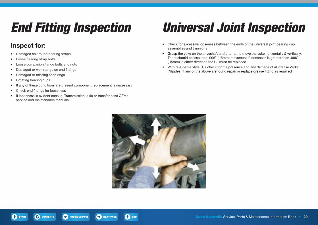
Universal Joint Inspection• Check for excessive looseness between the ends of the universal joint bearing cup
assemblies and trunnions
• Grasp the yoke on the driveshaft and attempt to move the yoke horizontally & vertically. There should be less then .006” (.15mm) movement If looseness is greater than .006” (.15mm) in either direction the UJ must be replaced
• With re-lubable style UJs check for the presence and any damage of all grease Zerks (Nipples) If any of the above are found repair or replace grease fitting as required
START PREVIOUS PAGE NEXT PAGE ENDCONTENTSC Dana Australia Service, Parts & Maintenance Information Book • 21
Slip Assembly Inspection• Check slip yoke to be sure plug is not loose damaged or missing
• Check for the presence of all grease Zerks (Nipples). If applicable. Grease fittings should not be missing loose or fractured
• Check the slip yoke seals & dust caps ensure that they are properly attached and not loose or damaged
• If there is excessive looseness between the mating components, with the presence of vibration, all slip assembly components should be replaced (10 Series only)
• For SPL slip yokes Check the slip member assembly for excessive radial looseness. Using a dial indicator, take hold of the tubing near the slip member with both hands and try to move vertically, up and down relative to the ground
• Apply effort perpendicular to shaft axis making note of total indicator travel.
• Allowable indicator travel is .000-.012 in
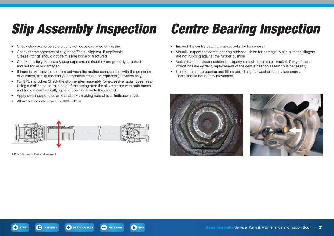
Centre Bearing Inspection• Inspect the centre bearing bracket bolts for looseness
• Visually inspect the centre bearing rubber cushion for damage. Make sure the slingers are not rubbing against the rubber cushion
• Verify that the rubber cushion is properly seated in the metal bracket. If any of these conditions are evident, replacement of the centre bearing assembly is necessary
• Check the centre bearing end fitting and fitting nut washer for any looseness. There should not be any movement
.012 in Maximum Radial Movement
START PREVIOUS PAGE NEXT PAGE ENDCONTENTSC Dana Australia Service, Parts & Maintenance Information Book • 22
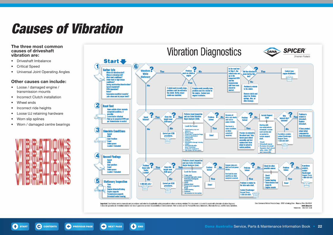
Causes of VibrationThe three most common causes of driveshaft vibration are: • Driveshaft Imbalance
• Critical Speed
• Universal Joint Operating Angles
Other causes can include:• Loose / damaged engine /
transmission mounts
• Incorrect Clutch installation
• Wheel ends
• Incorrect ride heights
• Loose UJ retaining hardware
• Worn slip splines
• Worn / damaged centre bearings
START PREVIOUS PAGE NEXT PAGE ENDCONTENTSC Dana Australia Service, Parts & Maintenance Information Book • 23
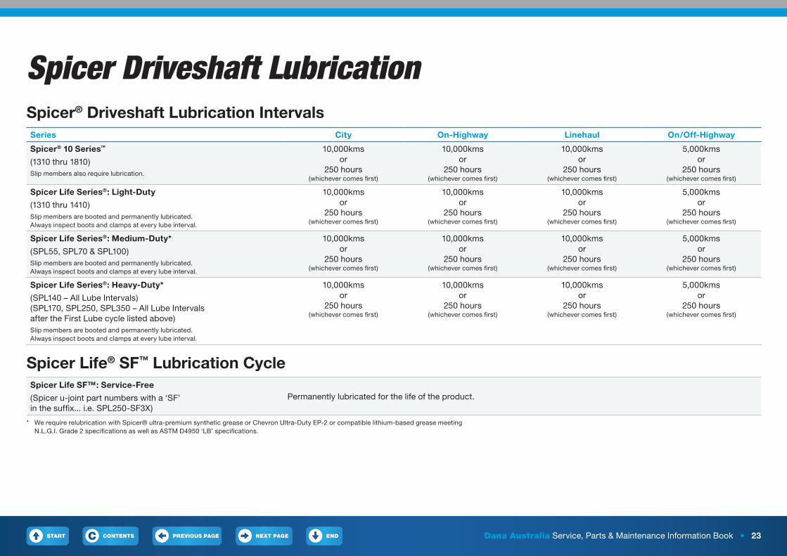
Spicer® Driveshaft Lubrication Intervals Series City On-Highway Linehaul On/Off-Highway
Spicer® 10 Series™
(1310 thru 1810)Slip members also require lubrication.
10,000kms or
250 hours (whichever comes first)
10,000kms or
250 hours (whichever comes first)
10,000kms or
250 hours (whichever comes first)
5,000kms or
250 hours (whichever comes first)
Spicer Life Series®: Light-Duty
(1310 thru 1410)Slip members are booted and permanently lubricated. Always inspect boots and clamps at every lube interval.
10,000kms or
250 hours (whichever comes first)
10,000kms or
250 hours (whichever comes first)
10,000kms or
250 hours (whichever comes first)
5,000kms or
250 hours (whichever comes first)
Spicer Life Series®: Medium-Duty*
(SPL55, SPL70 & SPL100)Slip members are booted and permanently lubricated. Always inspect boots and clamps at every lube interval.
10,000kms or
250 hours (whichever comes first)
10,000kms or
250 hours (whichever comes first)
10,000kms or
250 hours (whichever comes first)
5,000kms or
250 hours (whichever comes first)
Spicer Life Series®: Heavy-Duty*
(SPL140 – All Lube Intervals) (SPL170, SPL250, SPL350 – All Lube Intervals after the First Lube cycle listed above)Slip members are booted and permanently lubricated. Always inspect boots and clamps at every lube interval.
10,000kms or
250 hours (whichever comes first)
10,000kms or
250 hours (whichever comes first)
10,000kms or
250 hours (whichever comes first)
5,000kms or
250 hours (whichever comes first)
Spicer Life® SF™ Lubrication CycleSpicer Life SF™: Service-Free
(Spicer u-joint part numbers with a ‘SF’ in the suffix... i.e. SPL250-SF3X)
Permanently lubricated for the life of the product.
* We require relubrication with Spicer® ultra-premium synthetic grease or Chevron Ultra-Duty EP-2 or compatible lithium-based grease meeting N.L.G.I. Grade 2 specifications as well as ASTM D4950 ‘LB’ specifications.
Spicer Driveshaft Lubrication
START PREVIOUS PAGE NEXT PAGE ENDCONTENTSC Dana Australia Service, Parts & Maintenance Information Book • 24
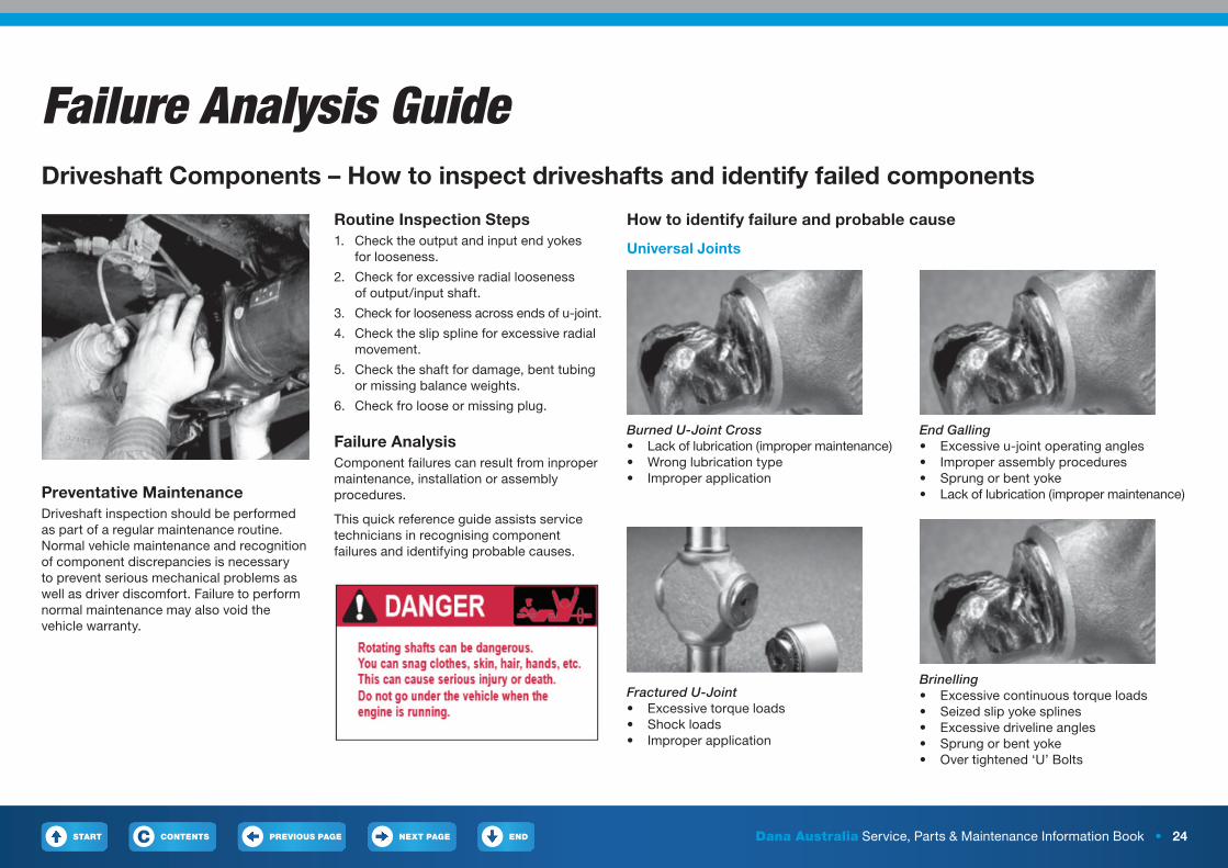
Failure Analysis GuideDriveshaft Components – How to inspect driveshafts and identify failed components
Preventative MaintenanceDriveshaft inspection should be performed as part of a regular maintenance routine. Normal vehicle maintenance and recognition of component discrepancies is necessary to prevent serious mechanical problems as well as driver discomfort. Failure to perform normal maintenance may also void the vehicle warranty.
Routine Inspection Steps1. Check the output and input end yokes
for looseness.
2. Check for excessive radial looseness of output/input shaft.
3. Check for looseness across ends of u-joint.
4. Check the slip spline for excessive radial movement.
5. Check the shaft for damage, bent tubing or missing balance weights.
6. Check fro loose or missing plug.
Failure AnalysisComponent failures can result from inproper maintenance, installation or assembly procedures.
This quick reference guide assists service technicians in recognising component failures and identifying probable causes.
How to identify failure and probable cause
Universal Joints
Burned U-Joint Cross• Lack of lubrication (improper maintenance)• Wrong lubrication type• Improper application
Fractured U-Joint• Excessive torque loads• Shock loads• Improper application
End Galling• Excessive u-joint operating angles• Improper assembly procedures• Sprung or bent yoke• Lack of lubrication (improper maintenance)
Brinelling• Excessive continuous torque loads• Seized slip yoke splines• Excessive driveline angles• Sprung or bent yoke• Over tightened ‘U’ Bolts
START PREVIOUS PAGE NEXT PAGE ENDCONTENTSC Dana Australia Service, Parts & Maintenance Information Book • 25
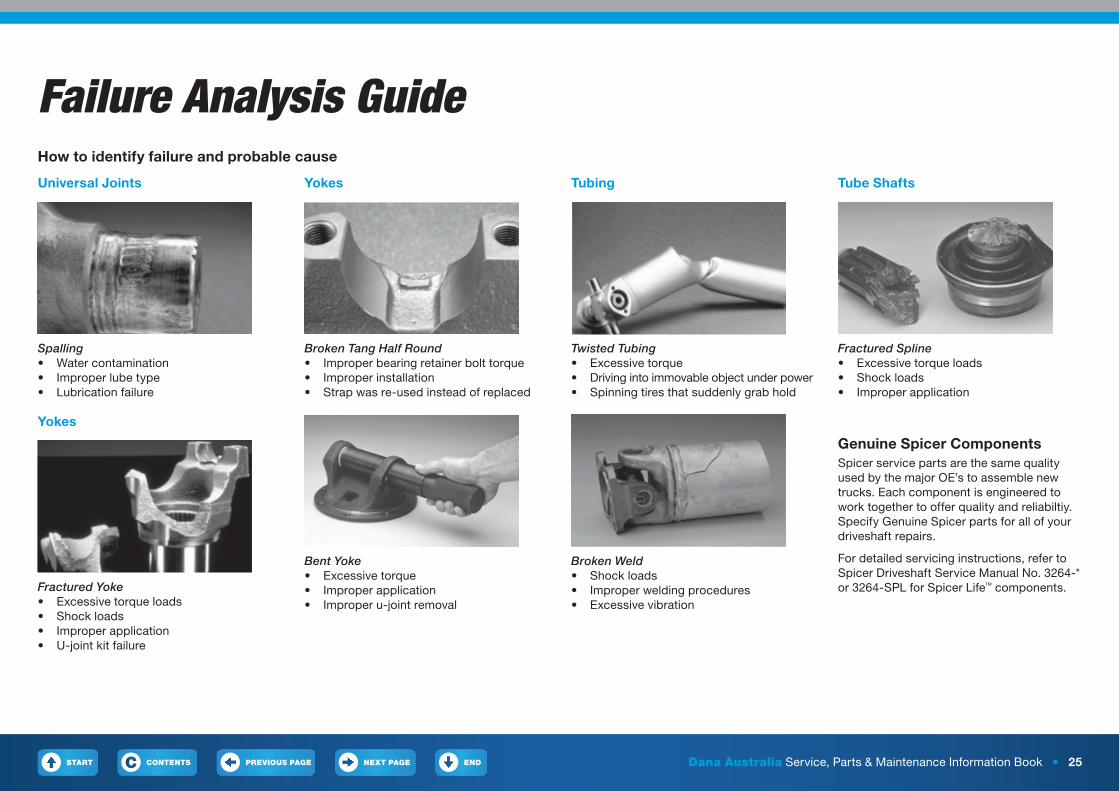
Failure Analysis GuideHow to identify failure and probable cause
Universal Joints
Spalling• Water contamination• Improper lube type• Lubrication failure
Yokes
Fractured Yoke• Excessive torque loads• Shock loads• Improper application• U-joint kit failure
Yokes
Broken Tang Half Round• Improper bearing retainer bolt torque• Improper installation• Strap was re-used instead of replaced
Bent Yoke• Excessive torque• Improper application• Improper u-joint removal
Tubing
Twisted Tubing• Excessive torque• Driving into immovable object under power• Spinning tires that suddenly grab hold
Broken Weld• Shock loads• Improper welding procedures• Excessive vibration
Tube Shafts
Fractured Spline• Excessive torque loads• Shock loads• Improper application
Genuine Spicer ComponentsSpicer service parts are the same quality used by the major OE’s to assemble new trucks. Each component is engineered to work together to offer quality and reliabiltiy. Specify Genuine Spicer parts for all of your driveshaft repairs.
For detailed servicing instructions, refer to Spicer Driveshaft Service Manual No. 3264-* or 3264-SPL for Spicer Life™ components.
START PREVIOUS PAGE NEXT PAGE ENDCONTENTSC Dana Australia Service, Parts & Maintenance Information Book • 26
SVL Universal Joints for Commercial ApplicationsAll-makes coverage for commercial universal jointsSVL u-joints deliver reliable quality across all makes of commercial applications, and they have the backing of Dana, the worldwide leader in driveline products and steering column parts. SVL universal joints are designed and tested to ensure a combined level of performance and value that the competition cannot match.
Six reasons to choose SVL products
1. Maximum ValueWhen genuine original equipment performance specifications are either not required or exceed your budget constraints, SVL products keep your vehicle rolling while protecting your bottom line.
2. Aftermarket EngineeredThe SVL product line fulfills the aftermarket’s need for reliable performance, and is fully validated by Dana’s experienced engineering team.
3. Guaranteed PerformanceSVL brand products have been designed and tested to deliver reliable performance. We have gone the extra mile to conduct quality and durability tests to ensure product performance. In addition, we provide a level of service that is unmatched.
4. Best in CategoryThe SVL brand products are engineering approved, performance tested and backed by Dana. SVL is the best choice in its brand category.
5. AvailabilityWhy expose yourself to increased inventory costs and delivery risks? SVL brand products are stocked in the U.S.A. by Dana and are available for immediate shipment. Delivery lead times for competing imported products in the value brand category can be as much as 120-180 days and could require a large inventory investment.
6. Backed by Dana Holding CorporationSVL brand products are backed by Dana Holding Corporation, the largest independent drivetrain manufacturer in the world. As an extension of Dana’s current product offerings, SVL offers valuable driveline solutions that are affordable and delivered with the service and reliability our customers have come to expect.
Dana is also proud to offer parts bearing the legendary Spicer brand. Spicer parts, including the full line of u-joints, axle shafts, centre bearings, and more, are engineered to the exact specifications of original equipment manufacturers. Visit the Spicer parts website to learn more about the benefits of genuine Spicer quality.
START PREVIOUS PAGE NEXT PAGE ENDCONTENTSC Dana Australia Service, Parts & Maintenance Information Book • 27
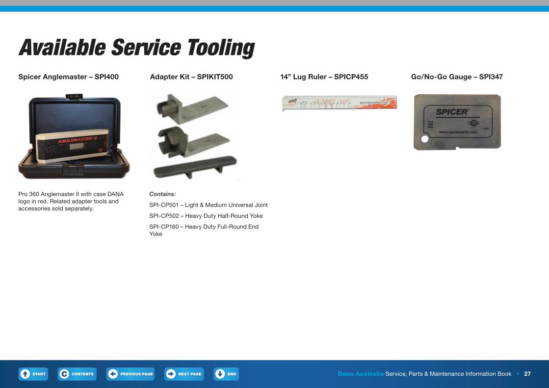
Available Service ToolingSpicer Anglemaster – SPI400 Adapter Kit – SPIKIT500 14” Lug Ruler – SPICP455
Pro 360 Anglemaster II with case DANA logo in red. Related adapter tools and accessories sold separately.
Contains:
SPI-CP501 – Light & Medium Universal Joint
SPI-CP502 – Heavy Duty Half-Round Yoke
SPI-CP160 – Heavy Duty Full-Round End Yoke
Go/No-Go Gauge – SPI347
START PREVIOUS PAGE NEXT PAGE ENDCONTENTSC Dana Australia Service, Parts & Maintenance Information Book • 28
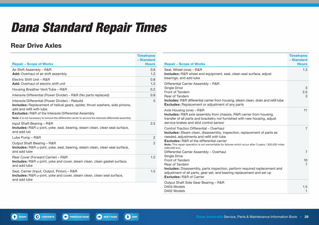
Dana Standard Repair TimesRear Drive Axles
Repair – Scope of Works
Timeframe – Standard
Hours
Air Shift Assembly – R&RAdd: Overhaul of air shift assembly
0.61.2
Electric Shift Unit – R&RAdd: Overhaul of electric shift unit
0.81.2
Housing Breather Vent/Tube – R&R 0.2
Interaxle Differential (Power Divider) – R&R (No parts replaced) 0.8
Interaxle Differential (Power Divider) – Rebuild Includes: Replacement of helical gears, spider, thrust washers, side pinions, add and refill with lube. Excludes: R&R of the Interaxle Differential AssemblyNote: It is not necessary to remove the differential carrier to service the interaxle differential assembly.
5
Input Shaft Bearing – R&R Includes: R&R u-joint, yoke, seal, bearing, steam clean, clean seal surface, and add lub
2.5
Lube Pump – R&R 2
Output Shaft Bearing – R&R Includes: R&R u-joint, yoke, seal, bearing, steam clean, clean seal surface, and add lube
2
Rear Cover (Forward Carrier) – R&R Includes: R&R u-joint, yoke and cover, steam clean, clean gasket surface, and add lube
1.5
Seal, Carrier (Input, Output, Pinion) – R&R Includes: R&R u-joint, yoke and cover, steam clean, clean seal surface, and add lube
1.5
Repair – Scope of Works
Timeframe – Standard
Hours
Seal, Wheel (one) – R&R Includes: R&R wheel end equipment, seal, clean seal surface, adjust bearings, and add lube
1.3
Differential Carrier Assembly – R&R Single DriveFront of TandemRear of Tandem Includes: R&R differential carrier from housing, steam clean, drain and refill lube Excludes: Replacement or adjustment of any parts
3
3.53
Axle Housing (one) – R&R Includes: R&R axle assembly from chassis, R&R carrier from housing, transfer of all parts and bracketry not furnished with new housing, adjust service brakes and skid control sensor
11
Control Traction Differential – Overhaul Includes: Steam clean, disassembly, inspection, replacement of parts as needed, adjustments and refill with lube Excludes: R&R of the differential carrier Note: This repair operation is not warrantable for failures which occur after 3 years / 300,000 miles (480,000 km).
7
Differential Carrier Assembly – Overhaul Single DriveFront of TandemRear of Tandem Includes: Disassembly, parts inspection, perform required replacement and adjustment of all parts, gear set, and bearing replacement and set up Excludes: R&R of Carrier
7
107
Output Shaft Side Gear Bearing – R&R D404 ModelsD402 Models
1.5
1
START PREVIOUS PAGE NEXT PAGE ENDCONTENTSC Dana Australia Service, Parts & Maintenance Information Book • 29
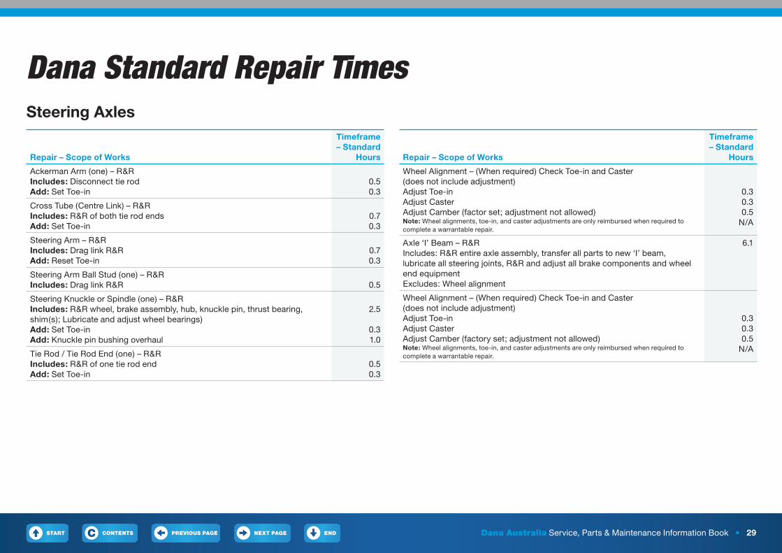
Dana Standard Repair TimesSteering Axles
Repair – Scope of Works
Timeframe – Standard
Hours
Ackerman Arm (one) – R&R Includes: Disconnect tie rod Add: Set Toe-in
0.5 0.3
Cross Tube (Centre Link) – R&R Includes: R&R of both tie rod ends Add: Set Toe-in
0.7 0.3
Steering Arm – R&R Includes: Drag link R&R Add: Reset Toe-in
0.7 0.3
Steering Arm Ball Stud (one) – R&R Includes: Drag link R&R
0.5
Steering Knuckle or Spindle (one) – R&R Includes: R&R wheel, brake assembly, hub, knuckle pin, thrust bearing, shim(s); Lubricate and adjust wheel bearings) Add: Set Toe-in Add: Knuckle pin bushing overhaul
2.5
0.3 1.0
Tie Rod / Tie Rod End (one) – R&R Includes: R&R of one tie rod end Add: Set Toe-in
0.5 0.3
Repair – Scope of Works
Timeframe – Standard
Hours
Wheel Alignment – (When required) Check Toe-in and Caster (does not include adjustment) Adjust Toe-in Adjust Caster Adjust Camber (factor set; adjustment not allowed)Note: Wheel alignments, toe-in, and caster adjustments are only reimbursed when required to complete a warrantable repair.
0.3 0.3 0.5
N/A
Axle ‘I’ Beam – R&R Includes: R&R entire axle assembly, transfer all parts to new ‘I’ beam, lubricate all steering joints, R&R and adjust all brake components and wheel end equipment Excludes: Wheel alignment
6.1
Wheel Alignment – (When required) Check Toe-in and Caster (does not include adjustment) Adjust Toe-in Adjust Caster Adjust Camber (factory set; adjustment not allowed)Note: Wheel alignments, toe-in, and caster adjustments are only reimbursed when required to complete a warrantable repair.
0.3 0.3 0.5
N/A
Dana Australia8 Hudson Court, Keysborough VIC 3173Phone: 1300 00 DANAwww.dana.com.au
Copyright Dana Australia 2017All rights reserved. Dana Australia.Printed in Australia, March 2017
START PREVIOUS PAGECONTENTSC