Embed Size (px)
Citation preview
SERVICE TRAINING CENTER
This document is destined for internal use only.The discribed settings and servicing must be carried outby service technicians qualified by HOBART.Reproduction of this document is prohibited without thewritten consent of Hobart GmbH.
© HOBART GmbH, Service Training Center
Issue: 2004-02-17 Rev. 2004-06-16 / REVISION C (Basic Data 6)
SERVICE MANUALAMX 900 / AMXX 1300 / AUXX 1300
AMXXT / AUXXT
Page 2 – AMX 900 / AMXX/AUXX 1300 / AMXXT/AUXXT © HOBART GmbH, Service Training Center
SERVICE TRAINING CENTER
CONTENTS
MODEL AND EQUIPMENT OVERVIEW – AMX 900............................................................................ 3
ELECTRICAL DATA – AMX 900............................................................................................................ 3
MODEL AND EQUIPMENT OVERVIEW – AMXX / AUXX 1300........................................................... 4
ELECTRICAL DATA – AMXX / AUXX 1300........................................................................................... 4
GENERAL TECHNICAL INFORMATION AMX / AMXX / AUXX ........................................................... 5
MODEL AND EQUIPMENT OVERVIEW – AMXXT / AUXXT ............................................................... 6
ELECTRICAL DATA – AMXXT / AUXXT ............................................................................................... 6
GENERAL TECHNICAL INFORMATION AMXXT / AUXXT .................................................................. 6
WATER CONNECTION AND RETROFITTING OF A DETERGENT DISPENSER .............................. 7
WHAT IS NEW ? ................................................................................................................................... 8
CONTROLS .......................................................................................................................................... 9
FIRST RUN ......................................................................................................................................... 10
DISHWASHER SETTINGS ................................................................................................................. 11
HYDRAULIC SCHEMATIC AND COMPONENTS – AMX / AMXX / AUXX ......................................... 12
HYDRAULIC SCHEMATIC AND COMPONENTS – AMXS / AMXXS / AUXXS.................................. 13
HYDRAULIC SCHEMATIC AND COMPONENTS – AMXXTS............................................................ 14
AIRGAP WITH BUILT-IN IMPELLER SWITCH ................................................................................... 15
SOFTENER......................................................................................................................................... 16
SOFTENER TEST PROGRAM ..................................................................................................... 17, 18
MAIN CONTROL BOARD - TEST PROGRAM ................................................................................... 18
BUTTON FUNCTIONS, SETTINGS AND TEST PROGRAM ....................................................... 19, 20
BASIC DATA SHEET 4 / REVISION N / EPROM 897503-2 ...................................................... 21, 22
CYCLE TIMES, CAPACITY AND PERFORMANCE ........................................................................... 23
NEW PRINTED CIRCUIT BOARD 897502-1EPROM 897503-2 ............................................................................................................................... 24
FILL, DRAIN, BOOSTER AND WASH PUMPAMX 900 WITHOUT SOFTENER ....................................................................................................... 25
FILL, DRAIN, BOOSTER AND WASH PUMPAMXX / AUXX 1300 WITH SOFTENER .............................................................................................. 26
FILL, DRAIN, BOOSTER AND WASH PUMP (R)AMXXT / AUXXT WITH SOFTENER .................................................................................................. 27
REPLACEMENT OF DRAIN BODY .................................................................................................... 28
WASH PUMPS – GENERAL TECHNICAL DATA................................................................................ 28
SERVICE TRAINING CENTER
© HOBART GmbH, Service Training Center AMX 900 / AMXX/AUXX 1300 / AMXXT/AUXXT – Page 3
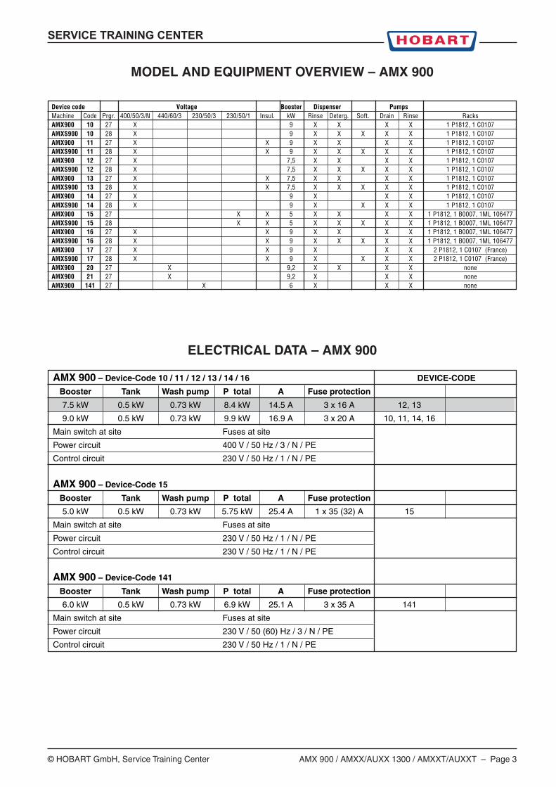
MODEL AND EQUIPMENT OVERVIEW – AMX 900
Device code Voltage Booster Dispenser PumpsMachine Code Prgr. 400/50/3/N 440/60/3 230/50/3 230/50/1 Insul. kW Rinse Deterg. Soft. Drain Rinse RacksAMX900 10 27 X 9 X X X X 1 P1812, 1 C0107AMXS900 10 28 X 9 X X X X X 1 P1812, 1 C0107AMX900 11 27 X X 9 X X X X 1 P1812, 1 C0107AMXS900 11 28 X X 9 X X X X X 1 P1812, 1 C0107AMX900 12 27 X 7,5 X X X X 1 P1812, 1 C0107AMXS900 12 28 X 7,5 X X X X X 1 P1812, 1 C0107AMX900 13 27 X X 7,5 X X X X 1 P1812, 1 C0107AMXS900 13 28 X X 7,5 X X X X X 1 P1812, 1 C0107AMX900 14 27 X 9 X X X 1 P1812, 1 C0107AMXS900 14 28 X 9 X X X X 1 P1812, 1 C0107AMX900 15 27 X X 5 X X X X 1 P1812, 1 B0007, 1ML 106477AMXS900 15 28 X X 5 X X X X X 1 P1812, 1 B0007, 1ML 106477AMX900 16 27 X X 9 X X X X 1 P1812, 1 B0007, 1ML 106477AMXS900 16 28 X X 9 X X X X X 1 P1812, 1 B0007, 1ML 106477AMX900 17 27 X X 9 X X X 2 P1812, 1 C0107 (France)AMXS900 17 28 X X 9 X X X X 2 P1812, 1 C0107 (France)AMX900 20 27 X 9,2 X X X X noneAMX900 21 27 X 9,2 X X X noneAMX900 141 27 X 6 X X X none
ELECTRICAL DATA – AMX 900
AMX 900 – Device-Code 10 / 11 / 12 / 13 / 14 / 16 DEVICE-CODE
Booster Tank Wash pump P total A Fuse protection
7.5 kW 0.5 kW 0.73 kW 8.4 kW 14.5 A 3 x 16 A 12, 13
9.0 kW 0.5 kW 0.73 kW 9.9 kW 16.9 A 3 x 20 A 10, 11, 14, 16
Main switch at site Fuses at site
Power circuit 400 V / 50 Hz / 3 / N / PE
Control circuit 230 V / 50 Hz / 1 / N / PE
AMX 900 – Device-Code 15
Booster Tank Wash pump P total A Fuse protection
5.0 kW 0.5 kW 0.73 kW 5.75 kW 25.4 A 1 x 35 (32) A 15
Main switch at site Fuses at site
Power circuit 230 V / 50 Hz / 1 / N / PE
Control circuit 230 V / 50 Hz / 1 / N / PE
AMX 900 – Device-Code 141
Booster Tank Wash pump P total A Fuse protection
6.0 kW 0.5 kW 0.73 kW 6.9 kW 25.1 A 3 x 35 A 141
Main switch at site Fuses at site
Power circuit 230 V / 50 (60) Hz / 3 / N / PE
Control circuit 230 V / 50 Hz / 1 / N / PE
Page 4 – AMX 900 / AMXX/AUXX 1300 / AMXXT/AUXXT © HOBART GmbH, Service Training Center
SERVICE TRAINING CENTER
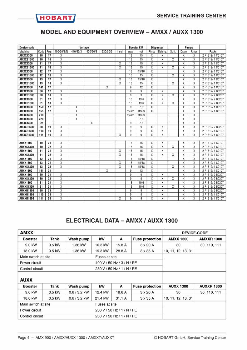
MODEL AND EQUIPMENT OVERVIEW – AMXX / AUXX 1300
Device code Voltage Booster kW Dispenser PumpsMachine Code Prgr. 400/50/3/N 440/60/3 400/60/3 230/50/3 Insul. new yet Rinse Deterg. Soft. Drain Rinse RacksAMXX1300 10 17 X 18 15 X X X X 2 P1812/ 1 C0107AMXXS1300 10 18 X 18 15 X X X X X 2 P1812/ 1 C0107AMXX1300 11 17 X X 18 15 X X X X 2 P1812/ 1 C0107AMXXS1300 11 18 X X 18 15 X X X X X 2 P1812/ 1 C0107AMXX1300 12 17 X 18 15/18 X X X 2 P1812/ 1 C0107AMXXS1300 12 18 X 18 15 X X X X 2 P1812/ 1 C0107AMXX1300 13 17 X X 18 15/18 X X X 2 P1812/ 1 C0107AMXXS1300 13 18 X X 18 15 X X X X 2 P1812/ 1 C0107AMXX1300 141 17 X 9 12 X X X 2 P1812/ 1 C0107AMXX1300 30 17 X 9 9 X X X X 2 P1812/ 2 B0207AMXXS1300 30 18 X 9 9 X X X X X 2 P1812/ 2 B0207AMXX1300 31 17 X 18 19,6 X X X X 2 P1812/ 2 B0207AMXXS1300 31 18 X 18 19,6 X X X X X 2 P1812/ 2 B0207AMXX1300 150 17 X 9 7,3 X X X 2 P1812/ 1 C0107AMXX1300 155 17 X steam steam X X X 2 P1812/ 1 C0107AMXX1300 210 X steam steam X XAMXX1300 220 X 7,3 X XAMXX1300 CV X 9 7,3 X XAMXXR1300 30 19 X 9 9 X X X X 2 P1812/ 2 B0207AMXXR1300 110 19 X 9 9 X X X X 2 P1812/ 1 C0107AMXXR1300 111 19 X X 9 9 X X X X 2 P1812/ 1 C0107
AUXX1300 10 21 X 18 15 X X X X 2 P1812/ 1 C0107AUXXS1300 10 22 X 18 15 X X X X X 2 P1812/ 1 C0107AUXX1300 11 21 X X 18 15 X X X X 2 P1812/ 1 C0107AUXXS1300 11 22 X X 18 15 X X X X X 2 P1812/ 1 C0107AUXX1300 12 21 X 18 15/18 X X X 2 P1812/ 1 C0107AUXX1300 13 21 X X 18 15/18 X X X 2 P1812/ 1 C0107AUXXS1300 13 22 X X 18 15/18 X X X X 2 P1812/ 1 C0107AUXX1300 141 21 X 9 12 X X X 2 P1812/ 1 C0107AUXX1300 30 21 X 9 9 X X X X 2 P1812/ 2 B0207AUXXS1300 30 22 X 9 9 X X X X X 2 P1812/ 2 B0207AUXX1300 31 21 X 18 19,6 X X X X 2 P1812/ 2 B0207AUXXS1300 31 21 X 18 19,6 X X X X X 2 P1812/ 2 B0207AUXXR1300 30 23 X 9 9 X X X X 2 P1812/ 2 B0207AUXXR1300 110 23 X 9 9 X X X X 2 P1812/ 1 C0107AUXXR1300 111 23 X X 9 9 X X X X 2 P1812/ 1 C0107
ELECTRICAL DATA – AMXX / AUXX 1300
AMXX DEVICE-CODE
Booster Tank Wash pump kW A Fuse protection AMXX 1300 AMXXR 1300
9.0 kW 0.5 kW 1.36 kW 10.3 kW 15.8 A 3 x 20 A 30 30, 110, 111
18.0 kW 0.5 kW 1.36 kW 19.3 kW 28.8 A 3 x 35 A 10, 11, 12, 13, 31
Main switch at site Fuses at site
Power circuit 400 V / 50 Hz / 3 / N / PE
Control circuit 230 V / 50 Hz / 1 / N / PE
AUXXBooster Tank Wash pump kW A Fuse protection AUXX 1300 AUXXR 1300
9.0 kW 0.5 kW 0.6 / 3.2 kW 12.4 kW 18.6 A 3 x 20 A 30 30, 110, 111
18.0 kW 0.5 kW 0.6 / 3.2 kW 21.4 kW 31.1 A 3 x 35 A 10, 11, 12, 13, 31
Main switch at site Fuses at site
Power circuit 230 V / 50 Hz / 1 / N / PE
Control circuit 230 V / 50 Hz / 1 / N / PE
SERVICE TRAINING CENTER
© HOBART GmbH, Service Training Center AMX 900 / AMXX/AUXX 1300 / AMXXT/AUXXT – Page 5
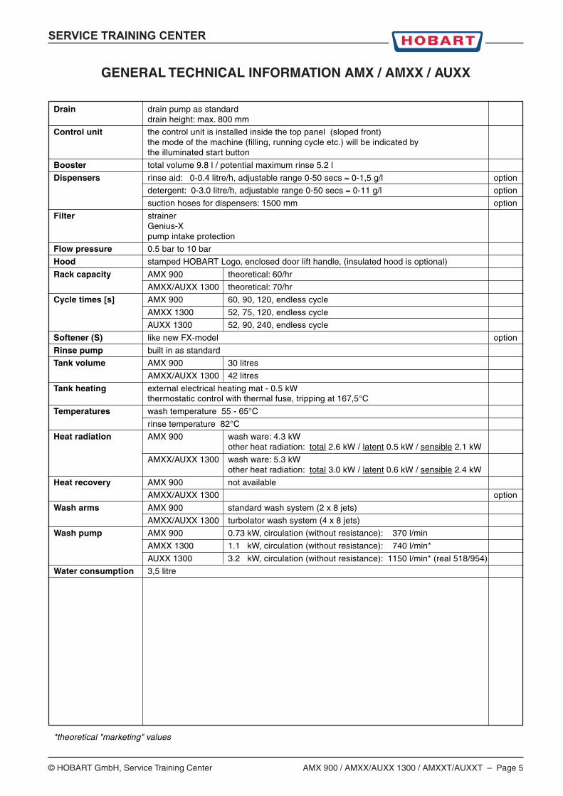
GENERAL TECHNICAL INFORMATION AMX / AMXX / AUXX
Drain drain pump as standarddrain height: max. 800 mm
Control unit the control unit is installed inside the top panel (sloped front)the mode of the machine (filling, running cycle etc.) will be indicated bythe illuminated start button
Booster total volume 9.8 l / potential maximum rinse 5.2 l
Dispensers rinse aid: 0-0.4 litre/h, adjustable range 0-50 secs ≈ 0-1,5 g/l option
detergent: 0-3.0 litre/h, adjustable range 0-50 secs ≈ 0-11 g/l option
suction hoses for dispensers: 1500 mm option
Filter strainerGenius-Xpump intake protection
Flow pressure 0.5 bar to 10 bar
Hood stamped HOBART Logo, enclosed door lift handle, (insulated hood is optional)
Rack capacity AMX 900 theoretical: 60/hr
AMXX/AUXX 1300 theoretical: 70/hr
Cycle times [s] AMX 900 60, 90, 120, endless cycle
AMXX 1300 52, 75, 120, endless cycle
AUXX 1300 52, 90, 240, endless cycle
Softener (S) like new FX-model option
Rinse pump built in as standard
Tank volume AMX 900 30 litres
AMXX/AUXX 1300 42 litres
Tank heating external electrical heating mat - 0.5 kWthermostatic control with thermal fuse, tripping at 167,5°C
Temperatures wash temperature 55 - 65°C
rinse temperature 82°C
Heat radiation AMX 900 wash ware: 4.3 kWother heat radiation: total 2.6 kW / latent 0.5 kW / sensible 2.1 kW
AMXX/AUXX 1300 wash ware: 5.3 kWother heat radiation: total 3.0 kW / latent 0.6 kW / sensible 2.4 kW
Heat recovery AMX 900 not available
AMXX/AUXX 1300 option
Wash arms AMX 900 standard wash system (2 x 8 jets)
AMXX/AUXX 1300 turbolator wash system (4 x 8 jets)
Wash pump AMX 900 0.73 kW, circulation (without resistance): 370 l/min
AMXX 1300 1.1 kW, circulation (without resistance): 740 l/min*
AUXX 1300 3.2 kW, circulation (without resistance): 1150 l/min* (real 518/954)
Water consumption 3,5 litre
*theoretical "marketing" values
Page 6 – AMX 900 / AMXX/AUXX 1300 / AMXXT/AUXXT © HOBART GmbH, Service Training Center
SERVICE TRAINING CENTER
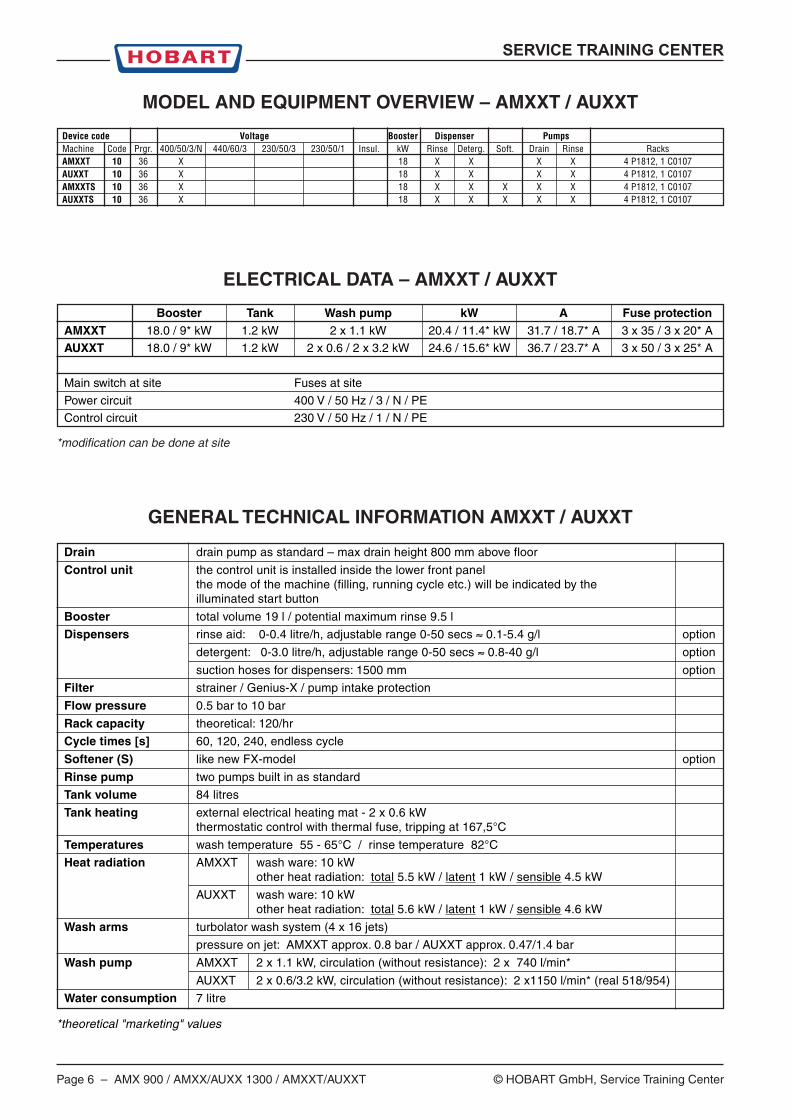
GENERAL TECHNICAL INFORMATION AMXXT / AUXXT
Drain drain pump as standard – max drain height 800 mm above floor
Control unit the control unit is installed inside the lower front panelthe mode of the machine (filling, running cycle etc.) will be indicated by theilluminated start button
Booster total volume 19 l / potential maximum rinse 9.5 l
Dispensers rinse aid: 0-0.4 litre/h, adjustable range 0-50 secs ≈ 0.1-5.4 g/l option
detergent: 0-3.0 litre/h, adjustable range 0-50 secs ≈ 0.8-40 g/l option
suction hoses for dispensers: 1500 mm option
Filter strainer / Genius-X / pump intake protection
Flow pressure 0.5 bar to 10 bar
Rack capacity theoretical: 120/hr
Cycle times [s] 60, 120, 240, endless cycle
Softener (S) like new FX-model option
Rinse pump two pumps built in as standard
Tank volume 84 litres
Tank heating external electrical heating mat - 2 x 0.6 kWthermostatic control with thermal fuse, tripping at 167,5°C
Temperatures wash temperature 55 - 65°C / rinse temperature 82°C
Heat radiation AMXXT wash ware: 10 kWother heat radiation: total 5.5 kW / latent 1 kW / sensible 4.5 kW
AUXXT wash ware: 10 kWother heat radiation: total 5.6 kW / latent 1 kW / sensible 4.6 kW
Wash arms turbolator wash system (4 x 16 jets)
pressure on jet: AMXXT approx. 0.8 bar / AUXXT approx. 0.47/1.4 bar
Wash pump AMXXT 2 x 1.1 kW, circulation (without resistance): 2 x 740 l/min*
AUXXT 2 x 0.6/3.2 kW, circulation (without resistance): 2 x1150 l/min* (real 518/954)
Water consumption 7 litre
*theoretical "marketing" values
MODEL AND EQUIPMENT OVERVIEW – AMXXT / AUXXT
Device code Voltage Booster Dispenser PumpsMachine Code Prgr. 400/50/3/N 440/60/3 230/50/3 230/50/1 Insul. kW Rinse Deterg. Soft. Drain Rinse RacksAMXXT 10 36 X 18 X X X X 4 P1812, 1 C0107AUXXT 10 36 X 18 X X X X 4 P1812, 1 C0107AMXXTS 10 36 X 18 X X X X X 4 P1812, 1 C0107AUXXTS 10 36 X 18 X X X X X 4 P1812, 1 C0107
ELECTRICAL DATA – AMXXT / AUXXT
Booster Tank Wash pump kW A Fuse protectionAMXXT 18.0 / 9* kW 1.2 kW 2 x 1.1 kW 20.4 / 11.4* kW 31.7 / 18.7* A 3 x 35 / 3 x 20* A
AUXXT 18.0 / 9* kW 1.2 kW 2 x 0.6 / 2 x 3.2 kW 24.6 / 15.6* kW 36.7 / 23.7* A 3 x 50 / 3 x 25* A
Main switch at site Fuses at site
Power circuit 400 V / 50 Hz / 3 / N / PE
Control circuit 230 V / 50 Hz / 1 / N / PE
*modification can be done at site
SERVICE TRAINING CENTER
© HOBART GmbH, Service Training Center AMX 900 / AMXX/AUXX 1300 / AMXXT/AUXXT – Page 7
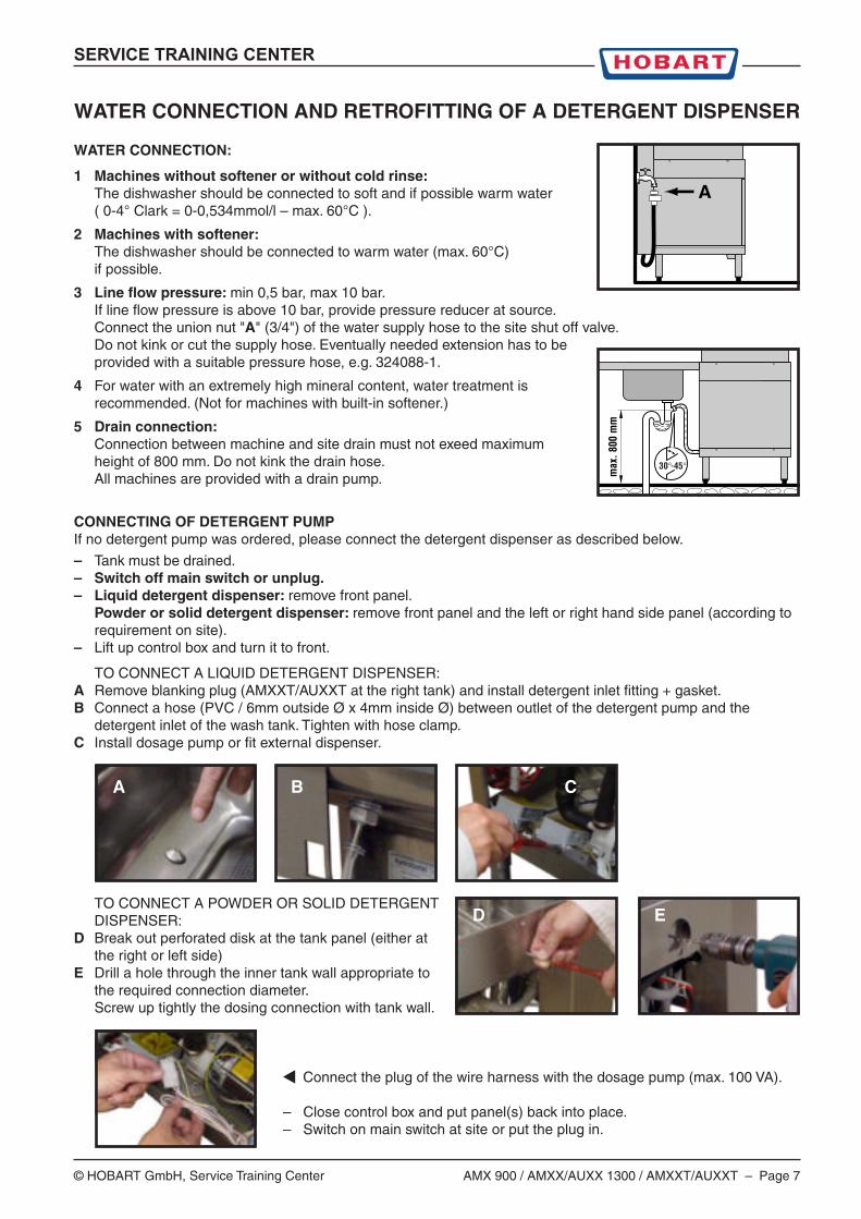
WATER CONNECTION AND RETROFITTING OF A DETERGENT DISPENSER
WATER CONNECTION:
1 Machines without softener or without cold rinse:The dishwasher should be connected to soft and if possible warm water( 0-4° Clark = 0-0,534mmol/l – max. 60°C ).
2 Machines with softener:The dishwasher should be connected to warm water (max. 60°C)if possible.
3 Line flow pressure: min 0,5 bar, max 10 bar.If line flow pressure is above 10 bar, provide pressure reducer at source.Connect the union nut "A" (3/4") of the water supply hose to the site shut off valve.Do not kink or cut the supply hose. Eventually needed extension has to beprovided with a suitable pressure hose, e.g. 324088-1.
4 For water with an extremely high mineral content, water treatment isrecommended. (Not for machines with built-in softener.)
5 Drain connection:Connection between machine and site drain must not exeed maximumheight of 800 mm. Do not kink the drain hose.All machines are provided with a drain pump.
CONNECTING OF DETERGENT PUMPIf no detergent pump was ordered, please connect the detergent dispenser as described below.
– Tank must be drained.– Switch off main switch or unplug.– Liquid detergent dispenser: remove front panel.
Powder or solid detergent dispenser: remove front panel and the left or right hand side panel (according torequirement on site).
– Lift up control box and turn it to front.
TO CONNECT A LIQUID DETERGENT DISPENSER:A Remove blanking plug (AMXXT/AUXXT at the right tank) and install detergent inlet fitting + gasket.B Connect a hose (PVC / 6mm outside Ø x 4mm inside Ø) between outlet of the detergent pump and the
detergent inlet of the wash tank. Tighten with hose clamp.C Install dosage pump or fit external dispenser.
TO CONNECT A POWDER OR SOLID DETERGENTDISPENSER:
D Break out perforated disk at the tank panel (either atthe right or left side)
E Drill a hole through the inner tank wall appropriate tothe required connection diameter.Screw up tightly the dosing connection with tank wall.
Connect the plug of the wire harness with the dosage pump (max. 100 VA).
– Close control box and put panel(s) back into place. – Switch on main switch at site or put the plug in.
A
max
. 800
mm
30°-45°
A B C
D E

Page 8 – AMX 900 / AMXX/AUXX 1300 / AMXXT/AUXXT © HOBART GmbH, Service Training Center
SERVICE TRAINING CENTER
WHAT IS NEW ?
GeneralThere are only four buttons on the keybord: "drain", "ON/OFF", "program"and "start".
AMX/AMXX/AUXX: The control unit is now inside the top panel installed (slopedfront) and via cable (on the back side of the machine) connected to the PCB.
AMXXT/AUXXT: The control unit is installed inside the lower front panel
The reed switch 775491-1 is identical with the FX/GX switch,the magnet is fitted inside the top panel.
Fill valve:The fill valve (5l/min) is part of the supply hose and is connected to the control.Filling is no longer controlled by pressure switch B3, a specific impeller integratedin the air gap is controlling the process (200 impulses mean 1 litre).The fill program is only terminated when the pressure switch B4/II (S4) closes(approx. eight fill cycles).
Control:The control 897502-1 is completely new. There is a separate fuse 775570-1for the control circuit (500V 6,3A T 6,3x32).
All settings can be done now by shortcuts, i.e. no manipulator is needed tochange values.
Location of terminals and the contactor:The terminals and the booster contactor are located inside a hinged control box.
Wash pump and rinse pump:The wash pump has an integrated self resetting thermal cut-out.There is no wash pump contactor anymore at the AMX 900.
Temperature sensors and tank heating:A temperature sensor (NTC - already used with the new FX) is integral part of theupper booster heating element (exchangeable).
The conventional tank heating element is replaced by a heater mat (0,5kW or 0,6kW)which is attached to the exterior wall of the wash tank. The heater mat has an integraltemperature limiter, tripping at 167,5°C (tripping does destroy the element).
The tank heating is now controlled by the second level of the pressure switch.The air chamber is now mounted at the right side of the wash tank.
Detergent and rinse aid dispenser:Now using peristaltic pumps (such as FX/GX).Detergent will be dosed as before into the wash tank.Delivery rate detergent: 3.0 l/hDelivery rate rinse aid: 0.4 l/h
SERVICE TRAINING CENTER
© HOBART GmbH, Service Training Center AMX 900 / AMXX/AUXX 1300 / AMXXT/AUXXT – Page 9
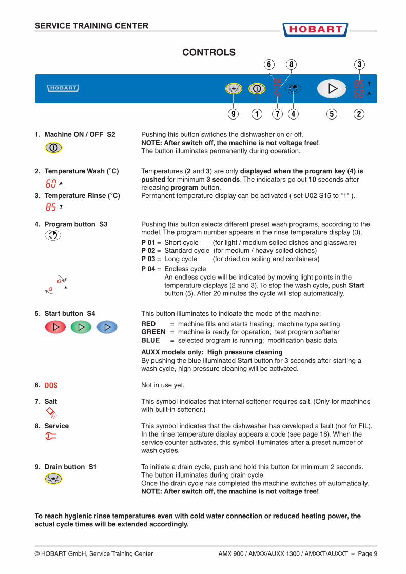
1. Machine ON / OFF S2 Pushing this button switches the dishwasher on or off.NOTE: After switch off, the machine is not voltage free!The button illuminates permanently during operation.
2. Temperature Wash (°C) Temperatures (2 and 3) are only displayed when the program key (4) ispushed for minimum 3 seconds. The indicators go out 10 seconds afterreleasing program button.
3. Temperature Rinse (°C) Permanent temperature display can be activated ( set U02 S15 to "1" ).
4. Program button S3 Pushing this button selects different preset wash programs, according to themodel. The program number appears in the rinse temperature display (3).
P 01 = Short cycle (for light / medium soiled dishes and glassware)P 02 = Standard cycle (for medium / heavy soiled dishes)P 03 = Long cycle (for dried on soiling and containers)
P 04 = Endless cycleAn endless cycle will be indicated by moving light points in thetemperature displays (2 and 3). To stop the wash cycle, push Startbutton (5). After 20 minutes the cycle will stop automatically.
5. Start button S4 This button illuminates to indicate the mode of the machine:
RED = machine fills and starts heating; machine type settingGREEN = machine is ready for operation; test program softenerBLUE = selected program is running; modification basic data
AUXX models only: High pressure cleaningBy pushing the blue illuminated Start button for 3 seconds after starting awash cycle, high pressure cleaning will be activated.
6. Not in use yet.
7. Salt This symbol indicates that internal softener requires salt. (Only for machineswith built-in softener.)
8. Service This symbol indicates that the dishwasher has developed a fault (not for FIL).In the rinse temperature display appears a code (see page 18). When theservice counter activates, this symbol illuminates after a preset number ofwash cycles.
9. Drain button S1 To initiate a drain cycle, push and hold this button for minimum 2 seconds.The button illuminates during drain cycle.Once the drain cycle has completed the machine switches off automatically.NOTE: After switch off, the machine is not voltage free!
To reach hygienic rinse temperatures even with cold water connection or reduced heating power, theactual cycle times will be extended accordingly.
CONTROLS
2547
38
19
6
DOS
DOS
Page 10 – AMX 900 / AMXX/AUXX 1300 / AMXXT/AUXXT © HOBART GmbH, Service Training Center
SERVICE TRAINING CENTER
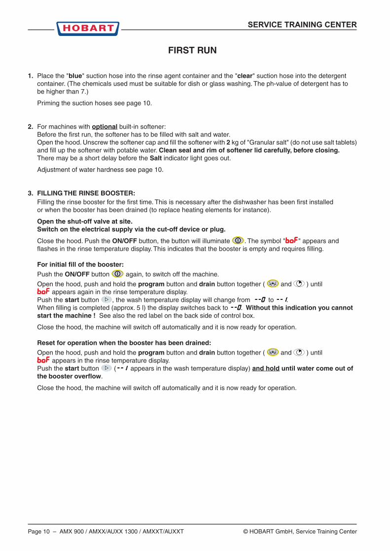
FIRST RUN
1. Place the "blue" suction hose into the rinse agent container and the "clear" suction hose into the detergentcontainer. (The chemicals used must be suitable for dish or glass washing. The ph-value of detergent has tobe higher than 7.)
Priming the suction hoses see page 10.
2. For machines with optional built-in softener:Before the first run, the softener has to be filled with salt and water.Open the hood. Unscrew the softener cap and fill the softener with 2 kg of "Granular salt" (do not use salt tablets)and fill up the softener with potable water. Clean seal and rim of softener lid carefully, before closing.There may be a short delay before the Salt indicator light goes out.
Adjustment of water hardness see page 10.
3. FILLING THE RINSE BOOSTER:Filling the rinse booster for the first time. This is necessary after the dishwasher has been first installedor when the booster has been drained (to replace heating elements for instance).
Open the shut-off valve at site.Switch on the electrical supply via the cut-off device or plug.
Close the hood. Push the ON/OFF button, the button will illuminate . The symbol "BOFBOFBOFBOFBOF" appears andflashes in the rinse temperature display. This indicates that the booster is empty and requires filling.
For initial fill of the booster:
Push the ON/OFF button again, to switch off the machine.
Open the hood, push and hold the program button and drain button together ( and ) untilBOFBOFBOFBOFBOF appears again in the rinse temperature display.Push the start button , the wash temperature display will change from --0--0--0--0--0 to --I--I--I--I--I.When filling is completed (approx. 5 l) the display switches back to --0--0--0--0--0. Without this indication you cannotstart the machine ! See also the red label on the back side of control box.
Close the hood, the machine will switch off automatically and it is now ready for operation.
Reset for operation when the booster has been drained:
Open the hood, push and hold the program button and drain button together ( and ) untilBOFBOFBOFBOFBOF appears in the rinse temperature display.Push the start button (--I --I --I --I --I appears in the wash temperature display) and hold until water come out ofthe booster overflow.
Close the hood, the machine will switch off automatically and it is now ready for operation.
SERVICE TRAINING CENTER
© HOBART GmbH, Service Training Center AMX 900 / AMXX/AUXX 1300 / AMXXT/AUXXT – Page 11
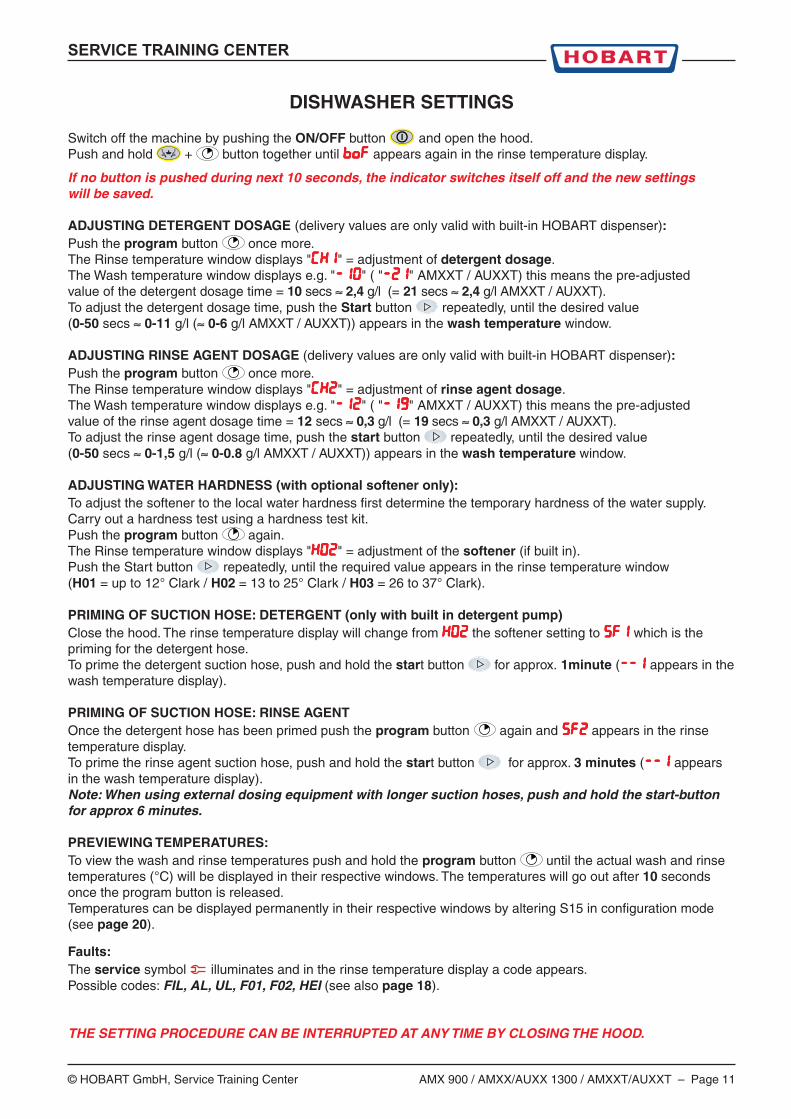
DISHWASHER SETTINGS
Switch off the machine by pushing the ON/OFF button and open the hood.Push and hold + button together until BOFBOFBOFBOFBOF appears again in the rinse temperature display.
If no button is pushed during next 10 seconds, the indicator switches itself off and the new settingswill be saved.
ADJUSTING DETERGENT DOSAGE (delivery values are only valid with built-in HOBART dispenser):Push the program button once more.The Rinse temperature window displays "(KI(KI(KI(KI(KI" = adjustment of detergent dosage.The Wash temperature window displays e.g. "-I0-I0-I0-I0-I0" ( "-21-21-21-21-21" AMXXT / AUXXT) this means the pre-adjustedvalue of the detergent dosage time = 10 secs ≈ 2,4 g/l (= 21 secs ≈ 2,4 g/l AMXXT / AUXXT).To adjust the detergent dosage time, push the Start button repeatedly, until the desired value(0-50 secs ≈ 0-11 g/l (≈ 0-6 g/l AMXXT / AUXXT)) appears in the wash temperature window.
ADJUSTING RINSE AGENT DOSAGE (delivery values are only valid with built-in HOBART dispenser):Push the program button once more.The Rinse temperature window displays "(K2(K2(K2(K2(K2" = adjustment of rinse agent dosage.The Wash temperature window displays e.g. "-I2-I2-I2-I2-I2" ( "-19-19-19-19-19" AMXXT / AUXXT) this means the pre-adjustedvalue of the rinse agent dosage time = 12 secs ≈ 0,3 g/l (= 19 secs ≈ 0,3 g/l AMXXT / AUXXT).To adjust the rinse agent dosage time, push the start button repeatedly, until the desired value(0-50 secs ≈ 0-1,5 g/l (≈ 0-0.8 g/l AMXXT / AUXXT)) appears in the wash temperature window.
ADJUSTING WATER HARDNESS (with optional softener only):To adjust the softener to the local water hardness first determine the temporary hardness of the water supply.Carry out a hardness test using a hardness test kit.Push the program button again.The Rinse temperature window displays "K02K02K02K02K02" = adjustment of the softener (if built in).Push the Start button repeatedly, until the required value appears in the rinse temperature window(H01 = up to 12° Clark / H02 = 13 to 25° Clark / H03 = 26 to 37° Clark).
PRIMING OF SUCTION HOSE: DETERGENT (only with built in detergent pump)Close the hood. The rinse temperature display will change from K02K02K02K02K02 the softener setting to SF1SF1SF1SF1SF1 which is thepriming for the detergent hose.To prime the detergent suction hose, push and hold the start button for approx. 1minute (--I--I--I--I--I appears in thewash temperature display).
PRIMING OF SUCTION HOSE: RINSE AGENTOnce the detergent hose has been primed push the program button again and SF2SF2SF2SF2SF2 appears in the rinsetemperature display.To prime the rinse agent suction hose, push and hold the start button for approx. 3 minutes (--I--I--I--I--I appearsin the wash temperature display).Note: When using external dosing equipment with longer suction hoses, push and hold the start-buttonfor approx 6 minutes.
PREVIEWING TEMPERATURES:To view the wash and rinse temperatures push and hold the program button until the actual wash and rinsetemperatures (°C) will be displayed in their respective windows. The temperatures will go out after 10 secondsonce the program button is released.Temperatures can be displayed permanently in their respective windows by altering S15 in configuration mode(see page 20).
Faults:The service symbol illuminates and in the rinse temperature display a code appears.Possible codes: FIL, AL, UL, F01, F02, HEI (see also page 18).
THE SETTING PROCEDURE CAN BE INTERRUPTED AT ANY TIME BY CLOSING THE HOOD.
Page 12 – AMX 900 / AMXX/AUXX 1300 / AMXXT/AUXXT © HOBART GmbH, Service Training Center
SERVICE TRAINING CENTER
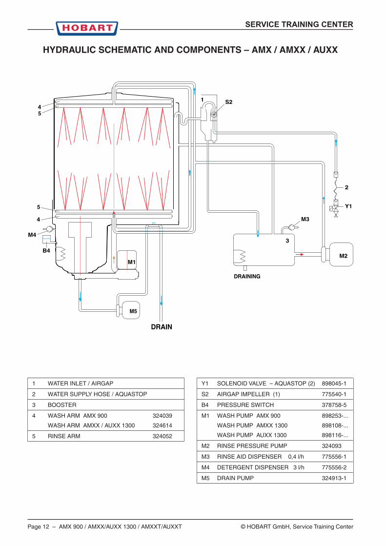
HYDRAULIC SCHEMATIC AND COMPONENTS – AMX / AMXX / AUXX
DRAINING
DRAIN
M1
M4
B4
4
4 M3
M2
3
S2
2
M5
5
5
1
Y1
1 WATER INLET / AIRGAP
2 WATER SUPPLY HOSE / AQUASTOP
3 BOOSTER
4 WASH ARM AMX 900 324039
WASH ARM AMXX / AUXX 1300 324614
5 RINSE ARM 324052
Y1 SOLENOID VALVE – AQUASTOP (2) 898045-1
S2 AIRGAP IMPELLER (1) 775540-1
B4 PRESSURE SWITCH 378758-5
M1 WASH PUMP AMX 900 898253-...
WASH PUMP AMXX 1300 898108-...
WASH PUMP AUXX 1300 898116-...
M2 RINSE PRESSURE PUMP 324093
M3 RINSE AID DISPENSER 0,4 l/h 775556-1
M4 DETERGENT DISPENSER 3 l/h 775556-2
M5 DRAIN PUMP 324913-1

SERVICE TRAINING CENTER
© HOBART GmbH, Service Training Center AMX 900 / AMXX/AUXX 1300 / AMXXT/AUXXT – Page 13
DRAINING
DRAIN
Y4.2
Y4.1 Y3.1
Y3.2
76 M1
M4
B4
4
4
M3
M2
3
S2
2
7 B A
M5
5
5
1
Y1
5 l/min
HYDRAULIC SCHEMATIC AND COMPONENTS – AMXS / AMXXS / AUXXS
1 WATER INLET / AIRGAP
2 WATER SUPPLY HOSE / AQUASTOP
3 BOOSTER
4 WASH ARM AMX 900 324039
WASH ARM AMXX / AUXX 1300 324614
5 RINSE ARM 324052
6 SALT CHAMBER
7 RESIN
Y1 SOLENOID VALVE – AQUASTOP (2) 898045-1
SOFTENER (6 + 7) 775530-2
Y3.1 VALVE RESIN A
Y3.2 VALVE RESIN B
Y4.1 VALVE RESIN B/A
Y4.2 VALVE BOOSTER / DRAIN
S2 AIRGAP IMPELLER (1) 775540-1
B4 PRESSURE SWITCH 378758-5
M1 WASH PUMP AMX 900 898253-...
WASH PUMP AMXX 1300 898108-...
WASH PUMP AUXX 1300 898116-...
M2 RINSE PRESSURE PUMP 324093
M3 RINSE AID DISPENSER 0,4 l/h 775556-1
M4 DETERGENT DISPENSER 3 l/h 775556-2
M5 DRAIN PUMP 324913-1
Page 14 – AMX 900 / AMXX/AUXX 1300 / AMXXT/AUXXT © HOBART GmbH, Service Training Center
SERVICE TRAINING CENTER
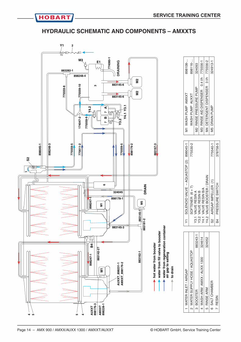
HYDRAULIC SCHEMATIC AND COMPONENTS – AMXXTS
ho
t w
ater
fro
m b
oo
ster
wat
er f
rom
fill
val
ve t
o b
oo
ster
wat
er f
rom
reg
ener
atio
n c
on
tain
er
air
gap
to
sal
tin
gto
dra
in
AU
XX
T_8
9823
1-1
AM
XX
T_8
9817
6-2
5
DR
AIN
4 5 4
1S
2
Y1 2
M3
M2
M2
E1
Y3.
1Y
4.1Y
4.2
3
Y3.
2
77
6
M5
B4
M1
M1
7740
80-1
8980
45-1
7755
59-8
8982
48-3
7755
59-5
7756
11-2
7755
59-5
8831
67-3
8981
79-2
8982
47-1
8831
42-2
?
8831
62-1
8982
47-1
8831
81-288
3145
-1
7755
59-9
1740
47-2
7755
59-1
0
883282-1
898248-4
883145-6
883145-6
883145-3
324045
898178-1
AU
XX
T89
8176
-3
AM
XX
T89
8228
-1A
B
DR
AIN
ING
Y1
SO
LEN
OID
VA
LVE
– A
QU
AS
TOP
(2)
8980
45-1
SO
FT
EN
ER
(6
+ 7
)77
5530
-2Y
3.1
VA
LVE
RE
SIN
AY
3.2
VA
LVE
RE
SIN
BY
4.1
VA
LVE
RE
SIN
B/A
Y4.
2V
ALV
E B
OO
ST
ER
/ D
RA
IN
S2
AIR
GA
P IM
PE
LLE
R (
1)77
5540
-1
B4
PR
ES
SU
RE
SW
ITC
H37
8758
-5
1W
ATE
R IN
LET
/ A
IRG
AP
2W
ATE
R S
UP
PLY
HO
SE
/ A
QU
AS
TOP
3B
OO
ST
ER
8832
43-1
4W
AS
H A
RM
AM
XX
/ A
UX
X 1
300
3246
14
5R
INS
E A
RM
3240
52
6S
ALT
CH
AM
BE
R
7R
ES
IN
M1
WA
SH
PU
MP
AM
XX
T89
8108
-...
WA
SH
PU
MP
AU
XX
T89
8116
-...
M2
RIN
SE
PR
ES
SU
RE
PU
MP
3240
93
M3
RIN
SE
AID
DIS
PE
NS
ER
0
.4 l/
h77
5556
-1
M4
DE
TE
RG
EN
T D
ISP
EN
SE
R
3 l/h
7755
56-2
M5
DR
AIN
PU
MP
3249
13-1

SERVICE TRAINING CENTER
© HOBART GmbH, Service Training Center AMX 900 / AMXX/AUXX 1300 / AMXXT/AUXXT – Page 15
Ball – to avoid blockingof the nozzle
Filling container
Impeller
Airgap
Regeneration container(approx 110 ml)Will be filled upcontinuousely duringfilling.Total contents with waterof fill hose approx 140 ml
container overflow
Connection for filling supply
Connection to regeneration
Machines without softenerthis is blanked off.
Overflowinto wash tank camber
Connectionfor filling the boostereither directly or via softener
The reed-switch on the small PCB S2 775540-11is actuated by the impeller magnet.The impeller monitors the incoming water flowby counting impulses and then relaying thatinformation back to the main PCB.(The count rate is 200 impulses per litre.)
AIRGAP WITH BUILT-IN IMPELLER SWITCH
WATER FLOW
Page 16 – AMX 900 / AMXX/AUXX 1300 / AMXXT/AUXXT © HOBART GmbH, Service Training Center
SERVICE TRAINING CENTER
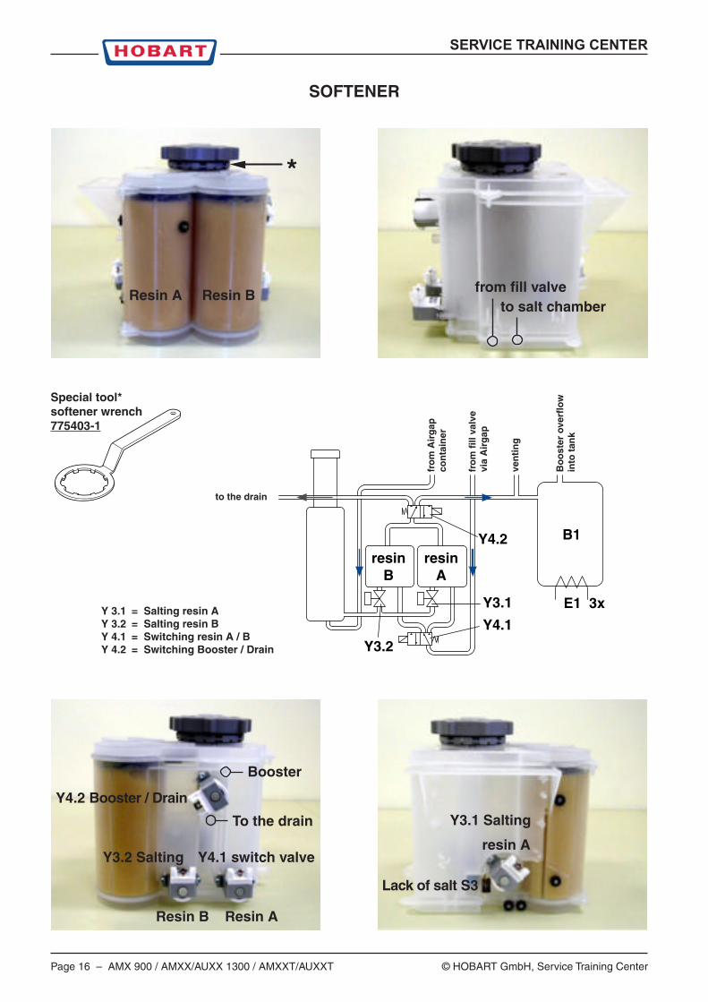
SOFTENER
Y 3.1 = Salting resin AY 3.2 = Salting resin BY 4.1 = Switching resin A / BY 4.2 = Switching Booster / Drain
Resin A Resin B from fill valveto salt chamber
Booster
Y4.2 Booster / Drain
To the drain
Y3.2 Salting Y4.1 switch valve
Resin B Resin A
Lack of salt S3
Y3.1 Salting
resin A
Special tool*softener wrench775403-1
*
fro
m A
irg
apco
nta
iner
to the drain
Y4.2
Y4.1
E1 3x
B1
Y3.1
Y3.2
resinB
resinA
Bo
ost
er o
verf
low
into
tan
k
fro
m f
ill v
alve
via
Air
gap
ven
tin
g
SERVICE TRAINING CENTER
© HOBART GmbH, Service Training Center AMX 900 / AMXX/AUXX 1300 / AMXXT/AUXXT – Page 17
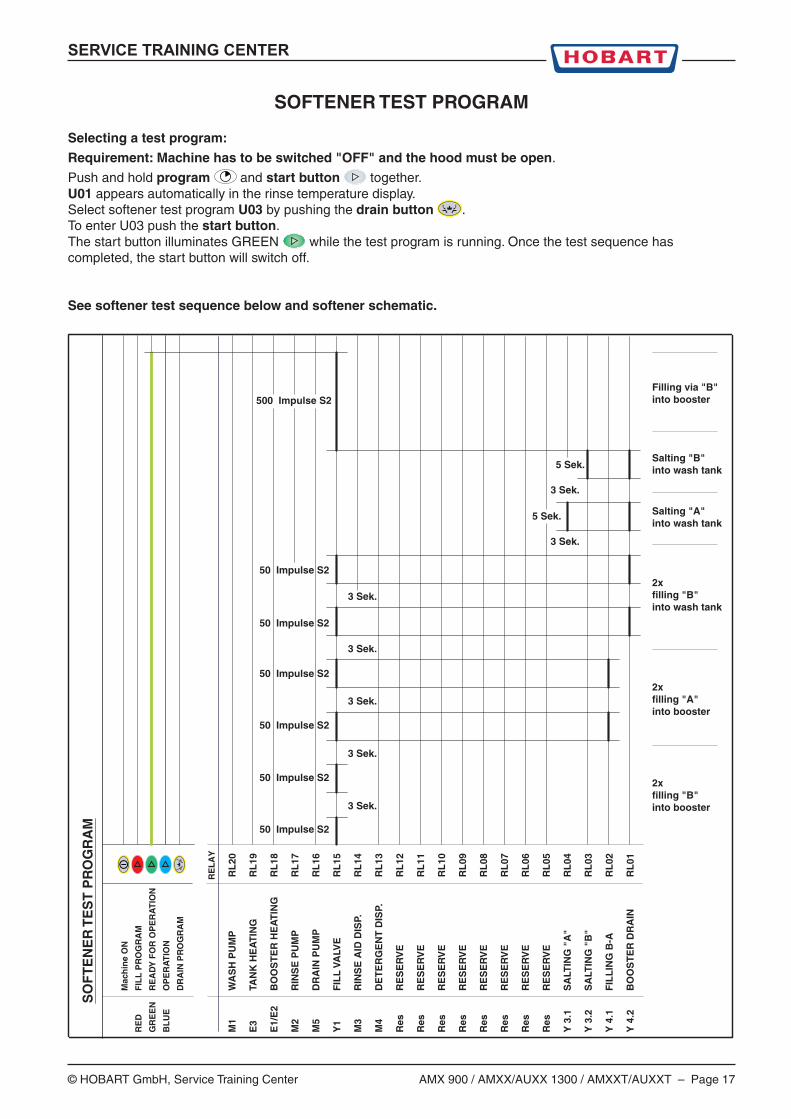
SOFTENER TEST PROGRAM
Selecting a test program:
Requirement: Machine has to be switched "OFF" and the hood must be open.
Push and hold program and start button together.U01 appears automatically in the rinse temperature display.Select softener test program U03 by pushing the drain button .To enter U03 push the start button.The start button illuminates GREEN while the test program is running. Once the test sequence hascompleted, the start button will switch off.
See softener test sequence below and softener schematic.
3 Sek.
3 Sek.
3 Sek.
3 Sek.
3 Sek.
50 Impulse S2
50 Impulse S2
50 Impulse S2
50 Impulse S2
50 Impulse S2
50 Impulse S2
Salting "B"into wash tank
Salting "A"into wash tank
2xfilling "A"into booster
2xfilling "B"into wash tank
2xfilling "B"into booster
SO
FT
EN
ER
TE
ST
PR
OG
RA
M
3 Sek.
3 Sek.
5 Sek.
5 Sek.
500 Impulse S2 Filling via "B"into booster
Mac
hin
e O
N
RE
DF
ILL
PR
OG
RA
M
GR
EE
NR
EA
DY
FO
R O
PE
RA
TIO
N
BL
UE
OP
ER
AT
ION
DR
AIN
PR
OG
RA
M
RE
LA
Y
M1
WA
SH
PU
MP
RL
20
E3
TAN
K H
EA
TIN
GR
L19
E1/
E2
BO
OS
TE
R H
EA
TIN
GR
L18
M2
RIN
SE
PU
MP
RL
17
M5
DR
AIN
PU
MP
RL
16
Y1
FIL
L V
ALV
ER
L15
M3
RIN
SE
AID
DIS
P.R
L14
M4
DE
TE
RG
EN
T D
ISP.
RL
13
Res
RE
SE
RV
ER
L12
Res
RE
SE
RV
ER
L11
Res
RE
SE
RV
ER
L10
Res
RE
SE
RV
ER
L09
Res
RE
SE
RV
ER
L08
Res
RE
SE
RV
ER
L07
Res
RE
SE
RV
ER
L06
Res
RE
SE
RV
ER
L05
Y 3
.1S
ALT
ING
"A
"R
L04
Y 3
.2S
ALT
ING
"B
"R
L03
Y 4
.1F
ILL
ING
B-A
RL
02
Y 4
.2B
OO
ST
ER
DR
AIN
RL
01
Page 18 – AMX 900 / AMXX/AUXX 1300 / AMXXT/AUXXT © HOBART GmbH, Service Training Center
SERVICE TRAINING CENTER
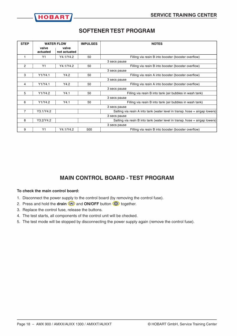
SOFTENER TEST PROGRAM
STEP WATER FLOW IMPULSES NOTESvalve valve
actuated not actuated
1 Y1 Y4.1/Y4.2 50 Filling via resin B into booster (booster overflow)3 secs pause
2 Y1 Y4.1/Y4.2 50 Filling via resin B into booster (booster overflow)3 secs pause
3 Y1/Y4.1 Y4.2 50 Filling via resin A into booster (booster overflow)3 secs pause
4 Y1/Y4.1 Y4.2 50 Filling via resin A into booster (booster overflow)3 secs pause
5 Y1/Y4.2 Y4.1 50 Filling via resin B into tank (air bubbles in wash tank)3 secs pause
6 Y1/Y4.2 Y4.1 50 Filling via resin B into tank (air bubbles in wash tank)3 secs pause
7 Y3.1/Y4.2 Salting via resin A into tank (water level in transp. hose + airgap lowers)3 secs pause
8 Y3.2/Y4.2 Salting via resin B into tank (water level in transp. hose + airgap lowers)3 secs pause
9 Y1 Y4.1/Y4.2 500 Filling via resin B into booster (booster overflow)
MAIN CONTROL BOARD - TEST PROGRAM
To check the main control board:
1. Disconnect the power supply to the control board (by removing the control fuse).
2. Press and hold the drain and ON/OFF button together.
3. Replace the control fuse, release the buttons.
4. The test starts, all components of the control unit will be checked.
5. The test mode will be stopped by disconnecting the power supply again (remove the control fuse).
SERVICE TRAINING CENTER
© HOBART GmbH, Service Training Center AMX 900 / AMXX/AUXX 1300 / AMXXT/AUXXT – Page 19
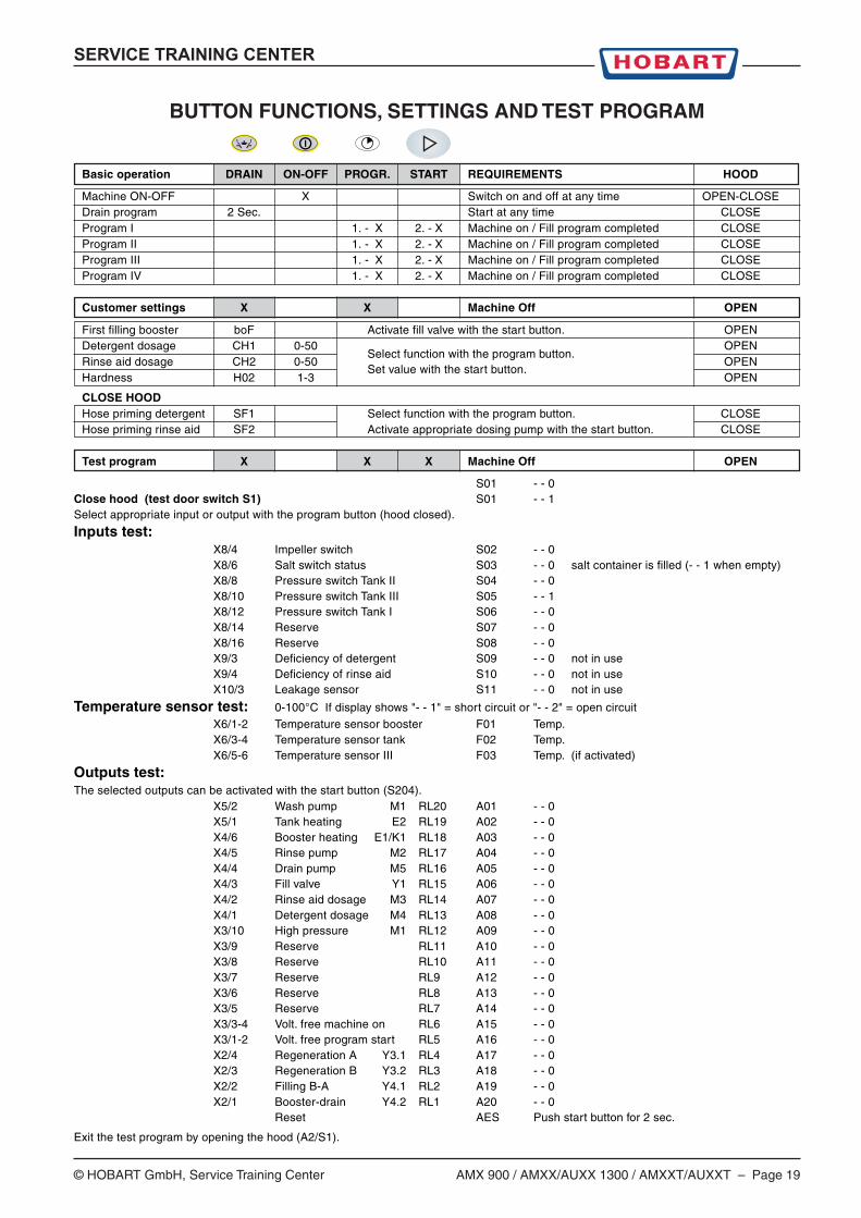
BUTTON FUNCTIONS, SETTINGS AND TEST PROGRAM
Basic operation DRAIN ON-OFF PROGR. START REQUIREMENTS HOOD
Machine ON-OFF X Switch on and off at any time OPEN-CLOSEDrain program 2 Sec. Start at any time CLOSEProgram I 1. - X 2. - X Machine on / Fill program completed CLOSEProgram II 1. - X 2. - X Machine on / Fill program completed CLOSEProgram III 1. - X 2. - X Machine on / Fill program completed CLOSEProgram IV 1. - X 2. - X Machine on / Fill program completed CLOSE
Customer settings X X Machine Off OPEN
First filling booster boF Activate fill valve with the start button. OPENDetergent dosage CH1 0-50
Select function with the program button.OPEN
Rinse aid dosage CH2 0-50 OPENHardness H02 1-3
Set value with the start button.OPEN
CLOSE HOODHose priming detergent SF1 Select function with the program button. CLOSEHose priming rinse aid SF2 Activate appropriate dosing pump with the start button. CLOSE
Test program X X X Machine Off OPEN
S01 - - 0Close hood (test door switch S1) S01 - - 1Select appropriate input or output with the program button (hood closed).
Inputs test:X8/4 Impeller switch S02 - - 0X8/6 Salt switch status S03 - - 0 salt container is filled (- - 1 when empty)X8/8 Pressure switch Tank II S04 - - 0X8/10 Pressure switch Tank III S05 - - 1X8/12 Pressure switch Tank I S06 - - 0X8/14 Reserve S07 - - 0X8/16 Reserve S08 - - 0X9/3 Deficiency of detergent S09 - - 0 not in useX9/4 Deficiency of rinse aid S10 - - 0 not in useX10/3 Leakage sensor S11 - - 0 not in use
Temperature sensor test: 0-100°C If display shows "- - 1" = short circuit or "- - 2" = open circuitX6/1-2 Temperature sensor booster F01 Temp.X6/3-4 Temperature sensor tank F02 Temp.X6/5-6 Temperature sensor III F03 Temp. (if activated)
Outputs test:The selected outputs can be activated with the start button (S204).
X5/2 Wash pump M1 RL20 A01 - - 0X5/1 Tank heating E2 RL19 A02 - - 0X4/6 Booster heating E1/K1 RL18 A03 - - 0X4/5 Rinse pump M2 RL17 A04 - - 0X4/4 Drain pump M5 RL16 A05 - - 0X4/3 Fill valve Y1 RL15 A06 - - 0X4/2 Rinse aid dosage M3 RL14 A07 - - 0X4/1 Detergent dosage M4 RL13 A08 - - 0X3/10 High pressure M1 RL12 A09 - - 0X3/9 Reserve RL11 A10 - - 0X3/8 Reserve RL10 A11 - - 0X3/7 Reserve RL9 A12 - - 0X3/6 Reserve RL8 A13 - - 0X3/5 Reserve RL7 A14 - - 0X3/3-4 Volt. free machine on RL6 A15 - - 0X3/1-2 Volt. free program start RL5 A16 - - 0X2/4 Regeneration A Y3.1 RL4 A17 - - 0X2/3 Regeneration B Y3.2 RL3 A18 - - 0X2/2 Filling B-A Y4.1 RL2 A19 - - 0X2/1 Booster-drain Y4.2 RL1 A20 - - 0
Reset AES Push start button for 2 sec.
Exit the test program by opening the hood (A2/S1).
Page 20 – AMX 900 / AMXX/AUXX 1300 / AMXXT/AUXXT © HOBART GmbH, Service Training Center
SERVICE TRAINING CENTER
BUTTON FUNCTIONS, SETTINGS AND TEST PROGRAM
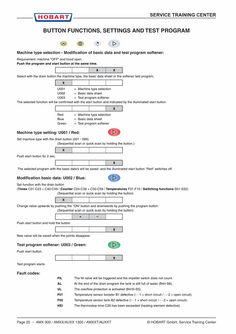
Machine type selection - Modification of basic data and test program softener:
Requirement: machine "OFF" and hood open.Push the program and start button at the same time.
X X
Select with the drain button the machine type, the basic data sheet or the softener test program.
X
U001 = Machine type selectionU002 = Basic data sheetU003 = Test program softener
The selected function will be confirmed with the start button and indicated by the illuminated start button.
X
Red = Machine type selectionBlue = Basic data sheetGreen = Test program softener
Machine type setting: U001 / Red:
Set machine type with the drain button (001 - 099).(Sequential scan or quick scan by holding the button.)
X
Push start button for 2 sec.
X
The selected program with the basic data’s will be saved and the illuminated start button "Red" switches off.
Modification basic data: U002 / Blue:
Set function with the drain button(Times C01-C23 + C40-C49 / Counter C24-C39 + C50-C59 / Temperatures F01-F10 / Switching functions S01-S32)
(Sequential scan or quick scan by holding the button)
X
Change value upwards by pushing the "ON" button and downwards by pushing the program button.(Sequential scan or quick scan by holding the button)
+ –
Push start button and hold the button
X
New value will be saved when the points disappear.
Test program softener: U003 / Green:
Push start button.
X
Test program starts.
Fault codes:FIL The fill valve will be triggered and the impeller switch does not count.
AL At the end of the drain program the tank is still full of water (B4/I-S6).
UL The overflow protection is activated (B4/III-S5).
F01 Temperature sensor booster B1 defective (- - 1 = short circuit / - - 2 = open circuit).
F02 Temperature sensor tank B2 defective (- - 1 = short circuit / - - 2 = open circuit).
HEI The thermostop time C20 has been exceeded (heating element defective).
SERVICE TRAINING CENTER
© HOBART GmbH, Service Training Center AMX 900 / AMXX/AUXX 1300 / AMXXT/AUXXT – Page 21
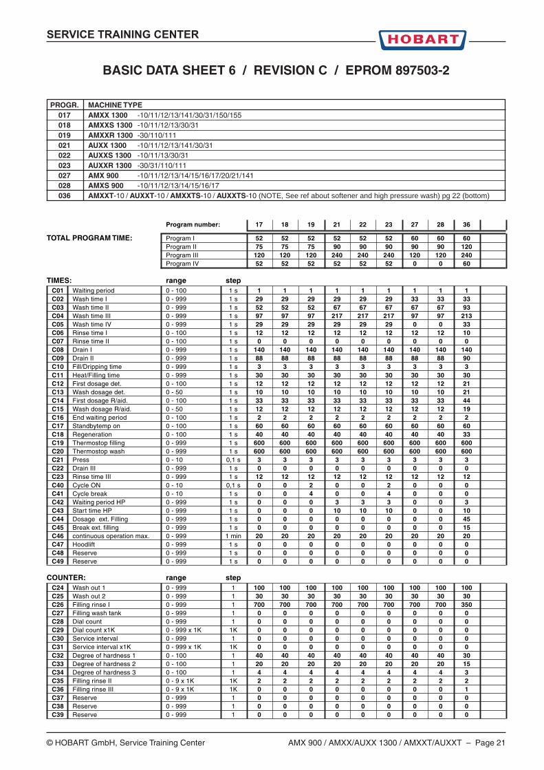
BASIC DATA SHEET 6 / REVISION C / EPROM 897503-2
PROGR. MACHINE TYPE017 AMXX 1300 -10/11/12/13/141/30/31/150/155018 AMXXS 1300 -10/11/12/13/30/31019 AMXXR 1300 -30/110/111021 AUXX 1300 -10/11/12/13/141/30/31022 AUXXS 1300 -10/11/13/30/31023 AUXXR 1300 -30/31/110/111027 AMX 900 -10/11/12/13/14/15/16/17/20/21/141028 AMXS 900 -10/11/12/13/14/15/16/17036 AMXXT-10 / AUXXT-10 / AMXXTS-10 / AUXXTS-10 (NOTE, See ref about softener and high pressure wash) pg 22 (bottom)
Program number: 17 18 19 21 22 23 27 28 36
TOTAL PROGRAM TIME: Program I 52 52 52 52 52 52 60 60 60Program II 75 75 75 90 90 90 90 90 120Program III 120 120 120 240 240 240 120 120 240Program IV 52 52 52 52 52 52 0 0 60
TIMES: range stepC01 Waiting period 0 - 100 1 s 1 1 1 1 1 1 1 1 1C02 Wash time I 0 - 999 1 s 29 29 29 29 29 29 33 33 33C03 Wash time II 0 - 999 1 s 52 52 52 67 67 67 67 67 93C04 Wash time III 0 - 999 1 s 97 97 97 217 217 217 97 97 213C05 Wash time IV 0 - 999 1 s 29 29 29 29 29 29 0 0 33C06 Rinse time I 0 - 100 1 s 12 12 12 12 12 12 12 12 10C07 Rinse time II 0 - 100 1 s 0 0 0 0 0 0 0 0 0C08 Drain I 0 - 999 1 s 140 140 140 140 140 140 140 140 140C09 Drain II 0 - 999 1 s 88 88 88 88 88 88 88 88 90C10 Fill/Dripping time 0 - 999 1 s 3 3 3 3 3 3 3 3 3C11 Heat/Filling time 0 - 999 1 s 30 30 30 30 30 30 30 30 30C12 First dosage det. 0 - 100 1 s 12 12 12 12 12 12 12 12 21C13 Wash dosage det. 0 - 50 1 s 10 10 10 10 10 10 10 10 21C14 First dosage R/aid. 0 - 100 1 s 33 33 33 33 33 33 33 33 44C15 Wash dosage R/aid. 0 - 50 1 s 12 12 12 12 12 12 12 12 19C16 End waiting period 0 - 100 1 s 2 2 2 2 2 2 2 2 2C17 Standbytemp on 0 - 100 1 s 60 60 60 60 60 60 60 60 60C18 Regeneration 0 - 100 1 s 40 40 40 40 40 40 40 40 33C19 Thermostop filling 0 - 999 1 s 600 600 600 600 600 600 600 600 600C20 Thermostop wash 0 - 999 1 s 600 600 600 600 600 600 600 600 600C21 Press 0 - 10 0,1 s 3 3 3 3 3 3 3 3 3C22 Drain III 0 - 999 1 s 0 0 0 0 0 0 0 0 0C23 Rinse time III 0 - 999 1 s 12 12 12 12 12 12 12 12 12C40 Cycle ON 0 - 10 0,1 s 0 0 2 0 0 2 0 0 0C41 Cycle break 0 - 10 1 s 0 0 4 0 0 4 0 0 0C42 Waiting period HP 0 - 999 1 s 0 0 0 3 3 3 0 0 3C43 Start time HP 0 - 999 1 s 0 0 0 10 10 10 0 0 10C44 Dosage ext. Filling 0 - 999 1 s 0 0 0 0 0 0 0 0 45C45 Break ext. filling 0 - 999 1 s 0 0 0 0 0 0 0 0 15C46 continuous operation max. 0 - 999 1 min 20 20 20 20 20 20 20 20 20C47 Hoodlift 0 - 999 1 s 0 0 0 0 0 0 0 0 0C48 Reserve 0 - 999 1 s 0 0 0 0 0 0 0 0 0C49 Reserve 0 - 999 1 s 0 0 0 0 0 0 0 0 0
COUNTER: range stepC24 Wash out 1 0 - 999 1 100 100 100 100 100 100 100 100 100C25 Wash out 2 0 - 999 1 30 30 30 30 30 30 30 30 30C26 Filling rinse I 0 - 999 1 700 700 700 700 700 700 700 700 350C27 Filling wash tank 0 - 999 1 0 0 0 0 0 0 0 0 0C28 Dial count 0 - 999 1 0 0 0 0 0 0 0 0 0C29 Dial count x1K 0 - 999 x 1K 1K 0 0 0 0 0 0 0 0 0C30 Service interval 0 - 999 1 0 0 0 0 0 0 0 0 0C31 Service interval x1K 0 - 999 x 1K 1K 0 0 0 0 0 0 0 0 0C32 Degree of hardness 1 0 - 100 1 40 40 40 40 40 40 40 40 30C33 Degree of hardness 2 0 - 100 1 20 20 20 20 20 20 20 20 15C34 Degree of hardness 3 0 - 100 1 4 4 4 4 4 4 4 4 3C35 Filling rinse II 0 - 9 x 1K 1K 2 2 2 2 2 2 2 2 2C36 Filling rinse III 0 - 9 x 1K 1K 0 0 0 0 0 0 0 0 1C37 Reserve 0 - 999 1 0 0 0 0 0 0 0 0 0C38 Reserve 0 - 999 1 0 0 0 0 0 0 0 0 0C39 Reserve 0 - 999 1 0 0 0 0 0 0 0 0 0
Page 22 – AMX 900 / AMXX/AUXX 1300 / AMXXT/AUXXT © HOBART GmbH, Service Training Center
SERVICE TRAINING CENTER
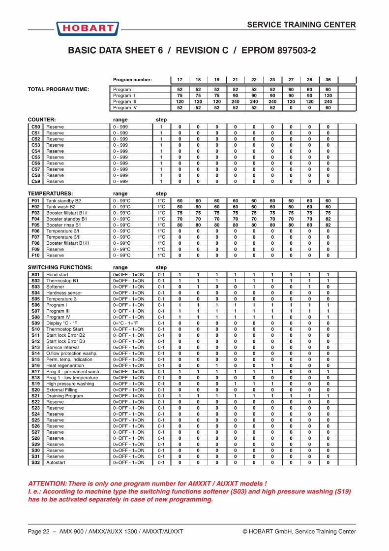
BASIC DATA SHEET 6 / REVISION C / EPROM 897503-2
Program number: 17 18 19 21 22 23 27 28 36
TOTAL PROGRAM TIME: Program I 52 52 52 52 52 52 60 60 60Program II 75 75 75 90 90 90 90 90 120Program III 120 120 120 240 240 240 120 120 240Program IV 52 52 52 52 52 52 0 0 60
COUNTER: range stepC50 Reserve 0 - 999 1 0 0 0 0 0 0 0 0 0C51 Reserve 0 - 999 1 0 0 0 0 0 0 0 0 0C52 Reserve 0 - 999 1 0 0 0 0 0 0 0 0 0C53 Reserve 0 - 999 1 0 0 0 0 0 0 0 0 0C54 Reserve 0 - 999 1 0 0 0 0 0 0 0 0 0C55 Reserve 0 - 999 1 0 0 0 0 0 0 0 0 0C56 Reserve 0 - 999 1 0 0 0 0 0 0 0 0 0C57 Reserve 0 - 999 1 0 0 0 0 0 0 0 0 0C58 Reserve 0 - 999 1 0 0 0 0 0 0 0 0 0C59 Reserve 0 - 999 1 0 0 0 0 0 0 0 0 0
TEMPERATURES: range stepF01 Tank standby B2 0 - 99°C 1°C 60 60 60 60 60 60 60 60 60F02 Tank wash B2 0 - 99°C 1°C 60 60 60 60 60 60 60 60 60F03 Booster fillstart B1/I 0 - 99°C 1°C 75 75 75 75 75 75 75 75 75F04 Booster standby B1 0 - 99°C 1°C 70 70 70 70 70 70 70 70 82F05 Booster rinse B1 0 - 99°C 1°C 80 80 80 80 80 80 80 80 82F06 Temperature 3/I 0 - 99°C 1°C 0 0 0 0 0 0 0 0 0F07 Temperature 3/II 0 - 99°C 1°C 0 0 0 0 0 0 0 0 0F08 Booster fillstart B1/II 0 - 99°C 1°C 0 0 0 0 0 0 0 0 0F09 Reserve 0 - 99°C 1°C 0 0 0 0 0 0 0 0 0F10 Reserve 0 - 99°C 1°C 0 0 0 0 0 0 0 0 0
SWITCHING FUNCTIONS: range stepS01 Hood start 0=OFF - 1=ON 0-1 1 1 1 1 1 1 1 1 1S02 Thermostop B1 0=OFF - 1=ON 0-1 1 1 1 1 1 1 1 1 1S03 Softener 0=OFF - 1=ON 0-1 0 1 0 0 1 0 0 1 0S04 Hardness sensor 0=OFF - 1=ON 0-1 0 0 0 0 0 0 0 0 0S05 Temperature 3 0=OFF - 1=ON 0-1 0 0 0 0 0 0 0 0 0S06 Program I 0=OFF - 1=ON 0-1 1 1 1 1 1 1 1 1 1S07 Program III 0=OFF - 1=ON 0-1 1 1 1 1 1 1 1 1 1S08 Program IV 0=OFF - 1=ON 0-1 1 1 1 1 1 1 0 0 1S09 Display °C - °F 0=°C - 1=°F 0-1 0 0 0 0 0 0 0 0 0S10 Thermostop Start 0=OFF - 1=ON 0-1 0 0 0 0 0 0 0 0 0S11 Start lock Error B2 0=OFF - 1=ON 0-1 0 0 0 0 0 0 0 0 0S12 Start lock Error B3 0=OFF - 1=ON 0-1 0 0 0 0 0 0 0 0 0S13 Service interval 0=OFF - 1=ON 0-1 0 0 0 0 0 0 0 0 0S14 O.flow protection washp. 0=OFF - 1=ON 0-1 0 0 0 0 0 0 0 0 0S15 Perm. temp. indication 0=OFF - 1=ON 0-1 0 0 0 0 0 0 0 0 0S16 Heat regeneration 0=OFF - 1=ON 0-1 0 0 1 0 0 1 0 0 0S17 Prog.4 - permanent wash. 0=OFF - 1=ON 0-1 1 1 1 1 1 1 0 0 1S18 Prog.1 - low temperature 0=OFF - 1=ON 0-1 0 0 0 0 0 0 0 0 0S19 High pressure washing 0=OFF - 1=ON 0-1 0 0 0 1 1 1 0 0 0S20 External Filling 0=OFF - 1=ON 0-1 0 0 0 0 0 0 0 0 0S21 Draining Program 0=OFF - 1=ON 0-1 1 1 1 1 1 1 1 1 1S22 Reserve 0=OFF - 1=ON 0-1 0 0 0 0 0 0 0 0 0S23 Reserve 0=OFF - 1=ON 0-1 0 0 0 0 0 0 0 0 0S24 Reserve 0=OFF - 1=ON 0-1 0 0 0 0 0 0 0 0 0S25 Reserve 0=OFF - 1=ON 0-1 0 0 0 0 0 0 0 0 0S26 Reserve 0=OFF - 1=ON 0-1 0 0 0 0 0 0 0 0 0S27 Reserve 0=OFF - 1=ON 0-1 0 0 0 0 0 0 0 0 0S28 Reserve 0=OFF - 1=ON 0-1 0 0 0 0 0 0 0 0 0S29 Reserve 0=OFF - 1=ON 0-1 0 0 0 0 0 0 0 0 0S30 Reserve 0=OFF - 1=ON 0-1 0 0 0 0 0 0 0 0 0S31 Reserve 0=OFF - 1=ON 0-1 0 0 0 0 0 0 0 0 0S32 Autostart 0=OFF - 1=ON 0-1 0 0 0 0 0 0 0 0 0
ATTENTION: There is only one program number for AMXXT / AUXXT models !I. e.: According to machine type the switching functions softener (S03) and high pressure washing (S19)has to be activated separately in case of new programming.
SERVICE TRAINING CENTER
© HOBART GmbH, Service Training Center AMX 900 / AMXX/AUXX 1300 / AMXXT/AUXXT – Page 23
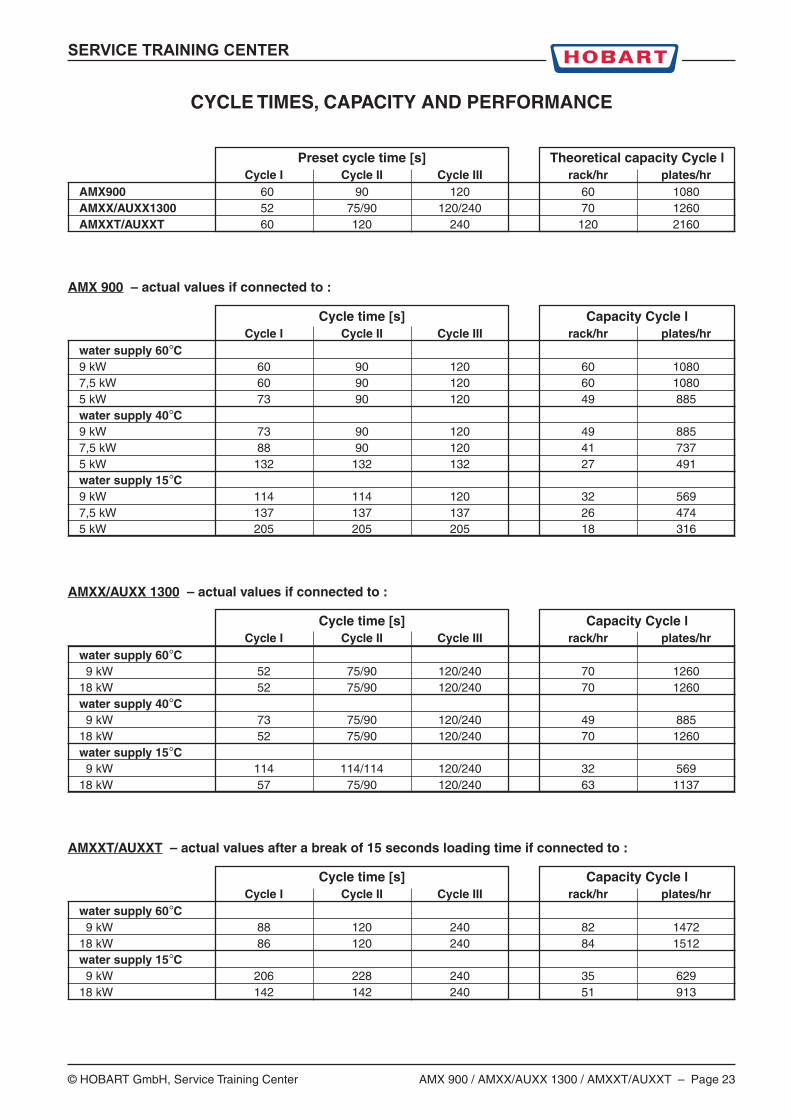
CYCLE TIMES, CAPACITY AND PERFORMANCE
Preset cycle time [s] Theoretical capacity Cycle lCycle I Cycle II Cycle III rack/hr plates/hr
AMX900 60 90 120 60 1080AMXX/AUXX1300 52 75/90 120/240 70 1260AMXXT/AUXXT 60 120 240 120 2160
AMX 900 – actual values if connected to :
Cycle time [s] Capacity Cycle lCycle I Cycle II Cycle III rack/hr plates/hr
water supply 60°C9 kW 60 90 120 60 10807,5 kW 60 90 120 60 10805 kW 73 90 120 49 885water supply 40°C9 kW 73 90 120 49 8857,5 kW 88 90 120 41 7375 kW 132 132 132 27 491water supply 15°C9 kW 114 114 120 32 5697,5 kW 137 137 137 26 4745 kW 205 205 205 18 316
AMXX/AUXX 1300 – actual values if connected to :
Cycle time [s] Capacity Cycle lCycle I Cycle II Cycle III rack/hr plates/hr
water supply 60°C 9 kW 52 75/90 120/240 70 126018 kW 52 75/90 120/240 70 1260water supply 40°C 9 kW 73 75/90 120/240 49 88518 kW 52 75/90 120/240 70 1260water supply 15°C 9 kW 114 114/114 120/240 32 56918 kW 57 75/90 120/240 63 1137
AMXXT/AUXXT – actual values after a break of 15 seconds loading time if connected to :
Cycle time [s] Capacity Cycle lCycle I Cycle II Cycle III rack/hr plates/hr
water supply 60°C 9 kW 88 120 240 82 147218 kW 86 120 240 84 1512water supply 15°C 9 kW 206 228 240 35 62918 kW 142 142 240 51 913
Page 24 – AMX 900 / AMXX/AUXX 1300 / AMXXT/AUXXT © HOBART GmbH, Service Training Center
SERVICE TRAINING CENTER
X9X10
X11X12
X6
X1
X7
X8
X5X4
X3X2
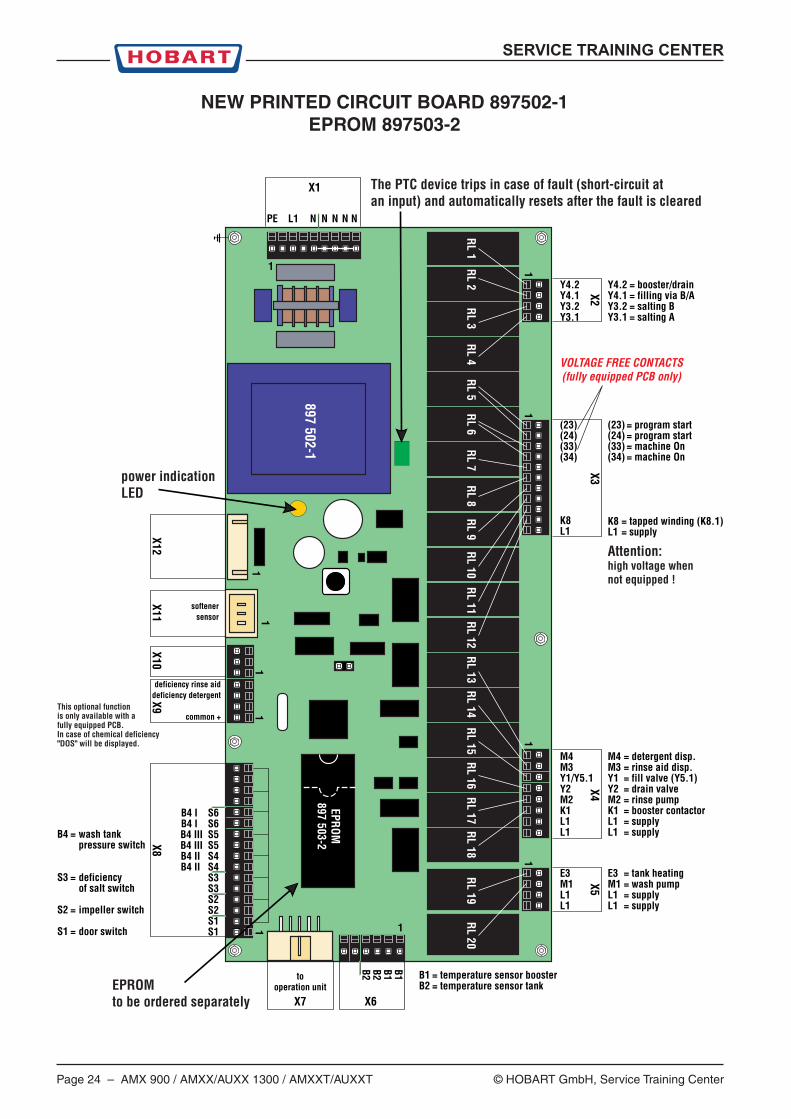
B4 I S6B4 I S6B4 III S5B4 III S5B4 II S4B4 II S4
S3S3S2S2S1S1
B4 = wash tankpressure switch
S3 = deficiency of salt switch
S2 = impeller switch
S1 = door switch
M4M3Y1/Y5.1Y2M2K1L1L1
(23)(24)(33)(34)
K8L1
Y4.2Y4.1Y3.2Y3.1
E3M1L1L1
M4 = detergent disp.M3 = rinse aid disp.Y1 = fill valve (Y5.1)Y2 = drain valveM2 = rinse pumpK1 = booster contactorL1 = supplyL1 = supply
(23) = program start(24) = program start(33) = machine On(34) = machine On
K8 = tapped winding (K8.1)L1 = supply
Y4.2 = booster/drainY4.1 = filling via B/AY3.2 = salting BY3.1 = salting A
E3 = tank heatingM1 = wash pumpL1 = supplyL1 = supply
B1 = temperature sensor boosterB2 = temperature sensor tank
B1B1B2B2
1 1
1
11
11
11
1
1
PE L1 N N N N N
EPROM897 503-2
RL 1RL 2
RL 3RL 4
RL 5RL 6
RL 7RL 8
RL 9RL 10
RL 11RL 12
RL 13RL 14
RL 15RL 16
RL 17RL 18
RL 19RL 20
897 502-1
The PTC device trips in case of fault (short-circuit at an input) and automatically resets after the fault is cleared
power indication LED
EPROM to be ordered separately
deficiency rinse aiddeficiency detergent
common +
softenersensor
tooperation unit
This optional function is only available with a fully equipped PCB.In case of chemical deficiency "DOS" will be displayed.
Attention:high voltage when not equipped !
VOLTAGE FREE CONTACTS(fully equipped PCB only)
NEW PRINTED CIRCUIT BOARD 897502-1EPROM 897503-2
SERVICE TRAINING CENTER
© HOBART GmbH, Service Training Center AMX 900 / AMXX/AUXX 1300 / AMXXT/AUXXT – Page 25
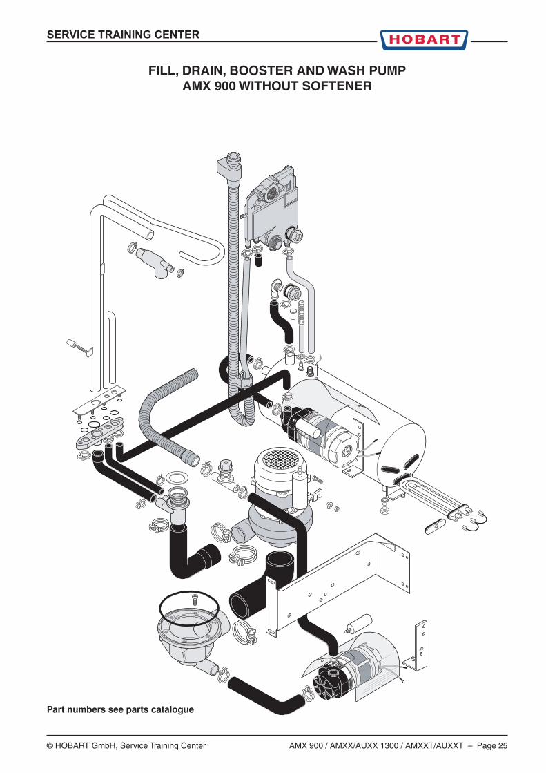
FILL, DRAIN, BOOSTER AND WASH PUMPAMX 900 WITHOUT SOFTENER
Part numbers see parts catalogue
Page 26 – AMX 900 / AMXX/AUXX 1300 / AMXXT/AUXXT © HOBART GmbH, Service Training Center
SERVICE TRAINING CENTER
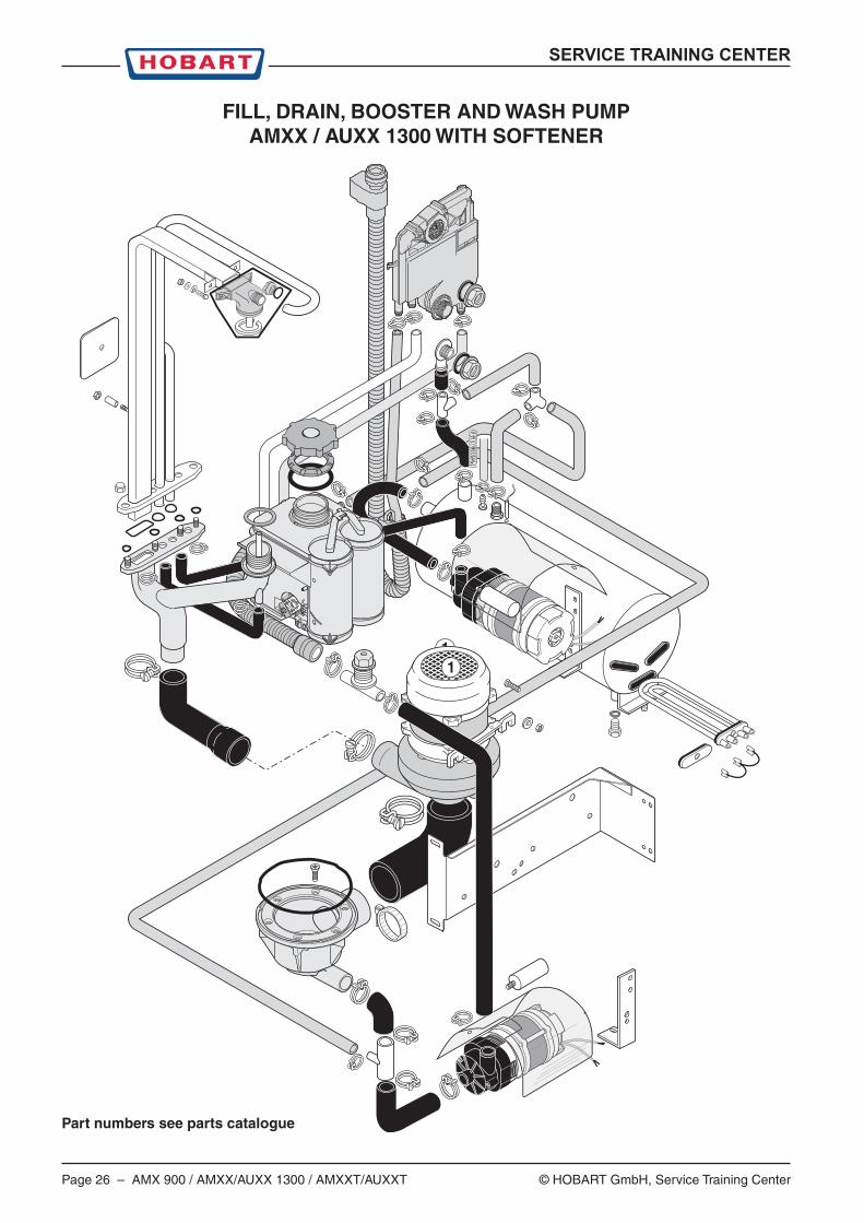
FILL, DRAIN, BOOSTER AND WASH PUMPAMXX / AUXX 1300 WITH SOFTENER
Part numbers see parts catalogue