Embed Size (px)
Citation preview
[email protected]. +34 945290010Fax. +34 945290381
3www.azolgas.esSERVICIO PERSONALIZADO PARA SU MERCADO GLOBALCUSTOMIZED SERVICE FOR YOUR GLOBAL MARKET
INDICE DE LAS SERIES MICROMICRO GAS SPRING INDEX
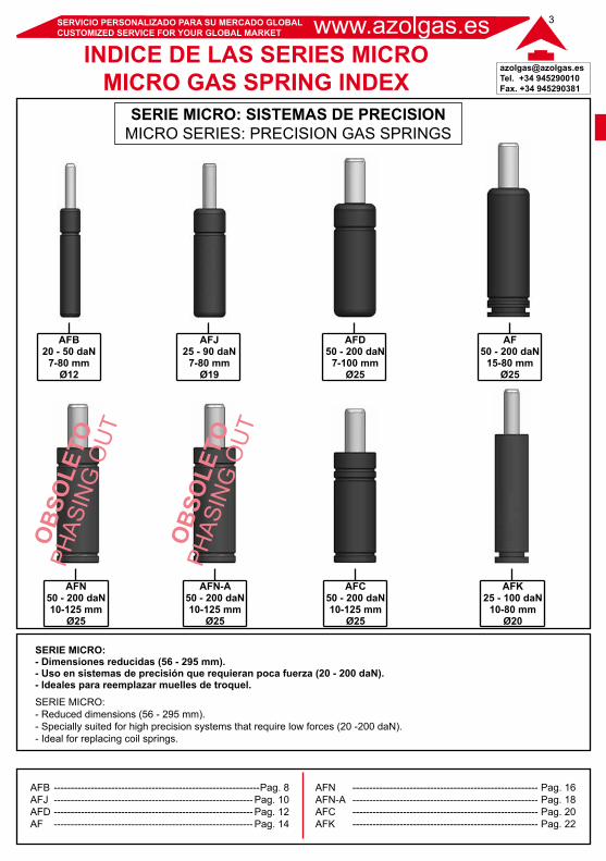
SERIE MICRO: SISTEMAS DE PRECISIONMICRO SERIES: PRECISION GAS SPRINGS
AFB20 - 50 daN
7-80 mmØ12
AFJ25 - 90 daN
7-80 mmØ19
AFD50 - 200 daN
7-100 mmØ25
AF50 - 200 daN
15-80 mmØ25
AFN50 - 200 daN10-125 mm
Ø25
AFN-A50 - 200 daN10-125 mm
Ø25
AFC50 - 200 daN10-125 mm
Ø25
AFK25 - 100 daN
10-80 mmØ20
SERIE MICRO:- Dimensiones reducidas (56 - 295 mm). - Uso en sistemas de precisión que requieran poca fuerza (20 - 200 daN).- Ideales para reemplazar muelles de troquel.SERIE MICRO:- Reduced dimensions (56 - 295 mm).- Specially suited for high precision systems that require low forces (20 -200 daN).- Ideal for replacing coil springs.
AFB -------------------------------------------------------------Pag. 8AFJ ----------------------------------------------------------- Pag. 10AFD ----------------------------------------------------------- Pag. 12AF ----------------------------------------------------------- Pag. 14
AFN ------------------------------------------------------- Pag. 16AFN-A ------------------------------------------------------- Pag. 18AFC ------------------------------------------------------- Pag. 20AFK ------------------------------------------------------- Pag. 22
www.azolgas.es SERVICIO PERSONALIZADO PARA SU MERCADO GLOBALCUSTOMIZED SERVICE FOR YOUR GLOBAL MARKET
[email protected]. +34 945290010Fax. +34 945290381
4
Se recomienda una reserva del 10% de la carreraA 10% stroke length allowance is recomended
Se fabrican cilindros especiales fuera de catalogo, bajo pedidoSpecial gas spring out of catalog are manufactured to specification request
Fluido presurizado / Pressure medium ...........................................................................................................Máx. presión de carga / Max. charging pressure ............................................................................................Mín. presión de carga / Min. charging pressure ..............................................................................................Temperatura de trabajo / Operating temperature ............................................................................................Máx. velocidad del vástago / Max. piston rod speed ......................................................................................Recargable / Refillable .....................................................................................................................................Conexión / Connection .....................................................................................................................................
N2
180 bar20 bar0° - 100° C1.6 m/sSi / YesNo
CARACTERISTICAS DE LA SERIE MICROABOUT MICRO SERIES
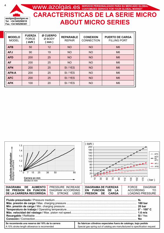
MODELOMODEL
FUERZAFORCE( daN )
Ø CUERPOØ BODY( mm )
REPARABLEREPAIR
CONEXIONCONNECTION
PUERTO DE CARGAFILLING PORT
AFB 50 12 NO NO M6
AFJ 90 19 NO NO M6
AFD 200 25 NO NO M6
AF 200 25 NO NO M6
AFN 200 25 SI / YES NO M6
AFN-A 200 25 SI / YES NO M6
AFC 200 25 SI / YES NO M6
AFK 100 20 SI / YES NO M6
Coe
ficie
nte
mul
tiplic
ador
Mul
tiplie
r coe
ffici
ent
Carrera en mmStroke in mm
01.0
1.1
1.2
1.3
1.4
1.5
80503825157
DIAGRAMA DE AUMENTODE PRESION EN FUNCION DE LA CARRERA RECORRIDA
DIAGRAMA DE FUERZAS EN FUNCION DE LA PRESION DE CARGA
PRESSURE INCREASE DIAGRAM ACCORDINGTO STROKE USED
FORCE DIAGRAMACCORDING TO LOADING PRESSURE
AFK
AFAFD
AFC
AFJAFB
10 30 50 70 90 110
130
150
170
020406080
100120140160180200
( daN )
( bar )
[email protected]. +34 945290010Fax. +34 945290381
5www.azolgas.esSERVICIO PERSONALIZADO PARA SU MERCADO GLOBALCUSTOMIZED SERVICE FOR YOUR GLOBAL MARKET
CARACTERISTICAS TECNICASTECHNICAL FEATURES
REQUISITOS DE SEGURIDAD / SAFETY REQUIREMENTSLos resortes de gas son recipientes con gasnitrógeno a una presión máxima de 180 bar.
No manipule ningún elemento del mismo sinestar seguro de que el resorte de gas estádescargado o que sabe cómo proceder paradescargarlo.
Los resortes de gas cumplen con la Directiva97/23/CE de equipos a presión ( PED ), y llevan el marcaje CE sólo aquellos que así vienen determinados por lamisma.
No se deben manipular los resortes de gas porpersonal sin la preparación adecuada y sin lasinstrucciones de mantenimiento de resortes de gas de Azolgas.
Pequeños resortes de gas para sistemas de precisión y aplicaciones en general que requieran poca fuerza y se disponga de espacios reducidos. Pueden colocarse en taladros practicados en el troquel o sujetos mediante bridas.Small gas springs specially suited for high precision systems and general applications that require little forces and reduced spaces. They can be dropped into a pocket in the die or fastened by flanges.
Gas springs are containers charged with nitrogengas at maximum pressure of 180 bar.
Do not manipulate any part of gas springwithout being sure that it is completely discharged, or you are trained in handling the process of unload.
Azolgas gas springs meet European CommunityDirective 97/23/CE related to Pressure EquipmentDevices ( PED ), and only the CE Mark identification will be laser etched according to the mentioned Directive.
Never handle gas springs by personnel without theappropriate training, and always following the outlinedoperating instructions from Azolgas.
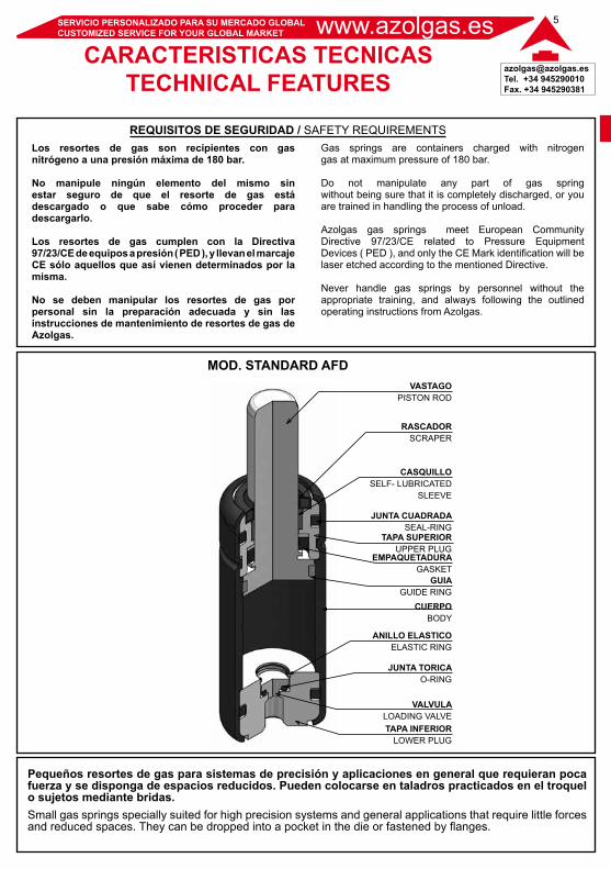
MOD. STANDARD AFDVASTAGO
PISTON ROD
RASCADORSCRAPER
CASQUILLOSELF- LUBRICATED
SLEEVE
JUNTA CUADRADASEAL-RING
TAPA SUPERIORUPPER PLUG
EMPAQUETADURAGASKET
GUIAGUIDE RING
CUERPOBODY
ANILLO ELASTICOELASTIC RING
JUNTA TORICAO-RING
VALVULALOADING VALVETAPA INFERIOR
LOWER PLUG
www.azolgas.es SERVICIO PERSONALIZADO PARA SU MERCADO GLOBALCUSTOMIZED SERVICE FOR YOUR GLOBAL MARKET
[email protected]. +34 945290010Fax. +34 945290381
6
RECOMENDACIONES DE UTILIZACIONOPERATING INSTRUCTIONS
La correcta aplicación de un resorte de gas va a evitarle problemas de fugas o sobrepresión, y va aproporcionarle la vida de uso para la que se diseñó.
INSTRUCCIONES DE INSTALACION:- El resorte de gas debe ir firmemente sujeto altroquel, bien por la rosca de la parte inferior del cuerpo o bien mediante las bridas que AzolGas ofrece en cada modelo.
- En caso de introducir el resorte de gas en una cajera taladrada en el troquel, el cuerpo debe ajustarse al agujero de forma que se impida su cabeceo ( serecomienda que la cajera tenga la profundidad del cuerpo ). Si el agujero fuese mayor, este ajuste puede realizarse mediante un casquillo plástico calado en el cuerpo. En caso de dejar al resorte de gas alojado libre en la cajera, el agujero debe tener como máximo 1mm más en diámetro que el diámetro del cuerpo.
- La rosca de la parte superior del vástago no debe usarse para sujetar el cilindro mediante un tornillo. Los errores de guiado y alineación pueden implicar un deterioro de los elementos de estanqueidad y reducir la vida del resorte. Esta rosca en el extremo superior del vástago debe usarse únicamente en tareas de mantenimiento.
- La colocación del resorte de gas debe hacerse lo más paralelamente posible a la fuerza aplicada, con lasuperficie del vástago perpendicular a dicha fuerza. Las superficies de apoyo de la base del cuerpo o de la brida y el vástago también deben ser perpendiculares a la fuerza aplicada, y deben tener una dureza suficiente.
- No se deben aplicar sobre el resorte de gas esfuerzos laterales. Prestar especial atención sobre vibraciones y movimientos laterales mientras el troquel está bajando, comprimiendo los cilindros.
PRESION MAX:- La presión máxima de carga del gas nitrógeno es de 180 bar a 20°C en estos modelos.
FLUIDOS:- Es importante evitar la presencia de fluidos opartículas sobre el resorte de gas. La mayoría deresortes de gas llevan un rascador que evita quepartículas o fluidos puedan introducirse a suinterior; no obstante la mejor protecciónviene de la ausencia de fluidos sobre susuperficie. Si el resorte de gas va alojado en una cajera que se puede inundar, cubriendo la partesuperior del cuerpo, se pueden hacer unosdrenajes en la cajera, de forma que el fluido no lainunde.
The correct gas spring application is going to avoidproblems related to leaks or overpressure, and it willprovide the life guarantee as it was designed.
MOUNTING INSTRUCTIONS:- Gas springs have to be firmly fastened to the die tool,either by the thread at the bottom of the body, or by the flange mounts offered by Azolgas for each gas springmodel.
- Should you install the gas spring in a bored pocket in the die, the gas spring body must be adjusted to the hole in order to avoid undesired lateral movement ( the boredpocket is recommended to have the same length as the gas spring body). If the bored pocket is larger than the cylinder body by more than 1mm, an adjustment can be made by a plastic sleeve on the body of the gas spring. Should the gas spring be placed into a pocket with no fixing sleeve, the bored pocket diameter should notexceed 1mm larger than the gas spring body diameter.
- The thread on the top of the rod cannot be used to mount the gas sping. This thread on the top of the rod must only be used in repair and maintenance tasks. Defectiveguiding in gas springs damages sealing parts and reduces gas spring life expectancy.
- Installation of gas springs into the tool must be made in parallel to the force used, with the rod surfaceperpendicular to the mentioned force. The surface of the gas spring body base, and the rod surface must be placed perpendicular to the force. The surface bearing areas for both body base and rod must have sufficient hardness.
- Gas springs cannot be exposed to lateral force. Payspecial attention to lateral forces and vibrations on the tool when the gas spring is cycled.
MAX. CHARGING PRESSURE:Maximum charging pressure for nitrogen gas is 180 bar at 20°C for these gas springs.
FLUIDS:It is important to keep gas springs clear of fluids or dirt. Most gas springs have a scraper to assist keeping fluids or dirt from entering the gas spring, nevertheless the best protection is the absence of fluids and dirt. Should the gas spring be installed into a bored pocket, this pocket could be flooded covering the upper part of gas spring body.Holes at the botton of the bored pocket could be made to let fluids go out through these holes and avoid the gas spring being flooded.
APLICACION DE UN RESORTE DE GAS / GAS SPRINGS APPLICATION
[email protected]. +34 945290010Fax. +34 945290381
7www.azolgas.esSERVICIO PERSONALIZADO PARA SU MERCADO GLOBALCUSTOMIZED SERVICE FOR YOUR GLOBAL MARKET
RECOMENDACIONES DE UTILIZACIONOPERATING INSTRUCTIONS
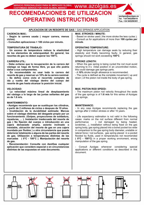
CADENCIA MAX.:- Según la carrera usada ( mayor carrera, menosciclos).- Consulten aplicaciones > 100 ciclos por minuto.
TEMPERATURA DE TRABAJO:- Un exceso de temperatura reduce la elasticidad de los elementos de estanqueidad. En general, losresortes de gas no deben superar los 100°C.
CARRERA UTIL:- Debe evitarse que la recuperación de la carrera del vástago se haga de forma libre, ya que ello podríadañar a sus componentes.- Es recomendable no usar toda la carrera delresorte de gas y reservar un 10% de la carrera nominal.- Se define como ciclo el recorrido completo de ida y vuelta del vástago dentro del cuerpo delresorte de gas hasta alcanzar la posición inicial.
VELOCIDAD:- La velocidad máxima lineal de desplazamientodel vástago a lo largo de las juntas sellantes del gas es de 1.6 m/s.
MANTENIMIENTO:- Azolgas recomienda que se sustituyan los cilindros, a partir de 2 millones de ciclos o despues de 10 años.- Invalidación de la durabilidad estimada: Marcassobre el vástago distintas del desgaste propio por un funcionamiento. (Golpes, proyecciones de soldadura, rayaduras, ... ). Instalación inadecuada del resorte de gas ( No fijación del cuerpo o introducción en unacajera demasiado amplia, asiento inclinado oinestable, ubicación del resorte de gas en una cajera inundada por fluídos ) u otra circunstancia que pueda deteriorar totalmente o alguna de las partes del resorte de gas. Utilización a temperaturas distintas de lasmarcadas ( 0°C - 100°C ). Manipulación del resorte de gas.- Recomendación: Consulte con AzolGas cualquier aplicación que considere especial o en circunstancias distintas de las expuestas en este documento.
MAX. STROKES / MINUTE:- Based on stroke used ( the more stroke the less cycles ).- Consult us for applications of more than 100 cycles per minute.
OPERATING TEMPERATURE:- High temperature can damage seals by reducing their elasticity and finally becoming faulty. In general, gas springs should not work exceeding 100°C.
STROKE LENGTH:- When the gas spring is being cycled the rod must avoid returning to it´s initial position in an uncontrolled motion, this could damage gas springs parts.- A 10% stroke length allowance is recommended.- The cycle is defined as the complete movement ( up and down ) of the piston rod inside the body of gas spring.
MAX. PISTON ROD SPEED:- The maximum piston rod velocity throughout the seals of the gas springs is of 1.6 m/s for this series of Azolgas gas springs.
MAINTENANCE:- In any case Azolgas recommends replacing the gas springs after 2 million strokes or after 10 years.
- Life expectancy estimation is not valid in the following cases: marks on the rod surface different from normalperformance ( rod damaged by being heated,scratches....), installation without being fixed on the gas spring body, gas spring placed into a bored pocket too wide in comparison to the gas spring body diameter, unstable or lateral force / rod surfaces, gas spring placed in a pocket flooded by fluids, used in temperatures not recomended( 0°C - 100°C) in a proper working enviroment, wrongmanipulation of the gas spring.
- Consult Azolgas whenever considering specialapplications or different conditions as described in thisdocument.
APLICACION DE UN RESORTE DE GAS / GAS SPRINGS APPLICATION
www.azolgas.es SERVICIO PERSONALIZADO PARA SU MERCADO GLOBALCUSTOMIZED SERVICE FOR YOUR GLOBAL MARKET
[email protected]. +34 945290010Fax. +34 945290381
8
Se recomienda una reserva del 10% de la carreraA 10% stroke length allowance is recomended
Se fabrican cilindros especiales fuera de catalogo, bajo pedidoSpecial gas spring out of catalog are manufactured to specification request
Fluido presurizado / Pressure medium ...........................................................................................................Máx. presión de carga / Max. charging pressure ............................................................................................Mín. presión de carga / Min. charging pressure ..............................................................................................Temperatura de trabajo / Operating temperature ............................................................................................Máx. velocidad del vástago / Max. piston rod speed ......................................................................................Recargable / Refillable .....................................................................................................................................Conexión / Connection .....................................................................................................................................
CILINDROS MICROMICRO GAS SPRINGS
N2
180 bar20 bar0° - 100° C1.6 m/sSi / YesNo
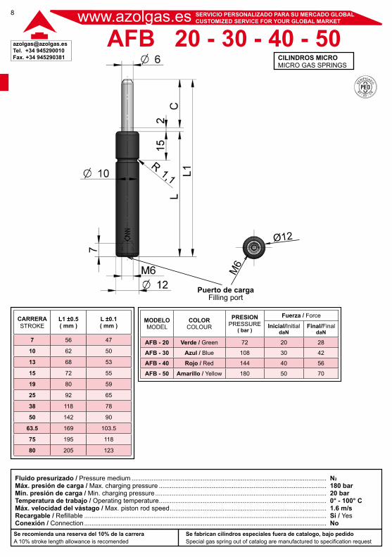
AFB 20 - 30 - 40 - 50
Puerto de cargaFilling port
Ø12M
6
CARRERASTROKE
L1 ±0.5( mm )
L ±0.1( mm )
7 56 47
10 62 50
13 68 53
15 72 55
19 80 59
25 92 65
38 118 78
50 142 90
63.5 169 103.5
75 195 118
80 205 123
MODELOMODEL
COLORCOLOUR
PRESIONPRESSURE
( bar )
Fuerza / Force
Inicial/InitialdaN
Final/FinaldaN
AFB - 20 Verde / Green 72 20 28
AFB - 30 Azul / Blue 108 30 42
AFB - 40 Rojo / Red 144 40 56
AFB - 50 Amarillo / Yellow 180 50 70
[email protected]. +34 945290010Fax. +34 945290381
9
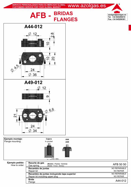
Ejemplo montaje:Flange mounting:
Ejemplo pedido:How to order:
Resorte de gasGas spring
BridaFlange
Recambio de juntasRepair kitRecambio de juntas incluyendo tapa superiorRepair kit including upper plug
CajeraIn pocket
www.azolgas.esSERVICIO PERSONALIZADO PARA SU MERCADO GLOBALCUSTOMIZED SERVICE FOR YOUR GLOBAL MARKET
(Modelo - Fuerza - Carrera)(Model - Force - Stroke)
A44A49
A49-012
A44-012
A44-012
NO REPARABLENO REPAIR
NO REPARABLENO REPAIR
AFB 50 50
BRIDASFLANGESAFB -
www.azolgas.es SERVICIO PERSONALIZADO PARA SU MERCADO GLOBALCUSTOMIZED SERVICE FOR YOUR GLOBAL MARKET
[email protected]. +34 945290010Fax. +34 945290381
10
Se recomienda una reserva del 10% de la carreraA 10% stroke length allowance is recomended
Se fabrican cilindros especiales fuera de catalogo, bajo pedidoSpecial gas spring out of catalog are manufactured to specification request
Fluido presurizado / Pressure medium ...........................................................................................................Máx. presión de carga / Max. charging pressure ............................................................................................Mín. presión de carga / Min. charging pressure ..............................................................................................Temperatura de trabajo / Operating temperature ............................................................................................Máx. velocidad del vástago / Max. piston rod speed ......................................................................................Recargable / Refillable .....................................................................................................................................Conexión / Connection .....................................................................................................................................
CILINDROS MICROMICRO GAS SPRINGS
N2
180 bar20 bar0° - 100° C1.6 m/sSi / YesNo
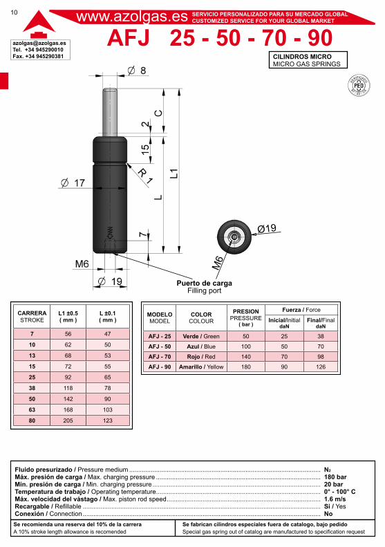
AFJ 25 - 50 - 70 - 90
Puerto de cargaFilling port
Ø19M
6
CARRERASTROKE
L1 ±0.5( mm )
L ±0.1( mm )
7 56 47
10 62 50
13 68 53
15 72 55
25 92 65
38 118 78
50 142 90
63 168 103
80 205 123
MODELOMODEL
COLORCOLOUR
PRESIONPRESSURE
( bar )
Fuerza / Force
Inicial/InitialdaN
Final/FinaldaN
AFJ - 25 Verde / Green 50 25 38
AFJ - 50 Azul / Blue 100 50 70
AFJ - 70 Rojo / Red 140 70 98
AFJ - 90 Amarillo / Yellow 180 90 126
[email protected]. +34 945290010Fax. +34 945290381
11
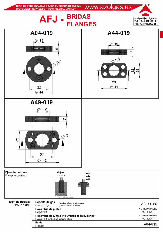
Ejemplo montaje:Flange mounting:
Ejemplo pedido:How to order:
Resorte de gasGas spring
BridaFlange
Recambio de juntasRepair kitRecambio de juntas incluyendo tapa superiorRepair kit including upper plug
CajeraIn pocket
www.azolgas.esSERVICIO PERSONALIZADO PARA SU MERCADO GLOBALCUSTOMIZED SERVICE FOR YOUR GLOBAL MARKET
(Modelo - Fuerza - Carrera)(Model - Force - Stroke)
A49-019
A44-019A04-019
BRIDASFLANGESAFJ -
A04-019
NO REPARABLENO REPAIR
NO REPARABLENO REPAIR
AFJ 90 50
A04A44A49
www.azolgas.es SERVICIO PERSONALIZADO PARA SU MERCADO GLOBALCUSTOMIZED SERVICE FOR YOUR GLOBAL MARKET
[email protected]. +34 945290010Fax. +34 945290381
12
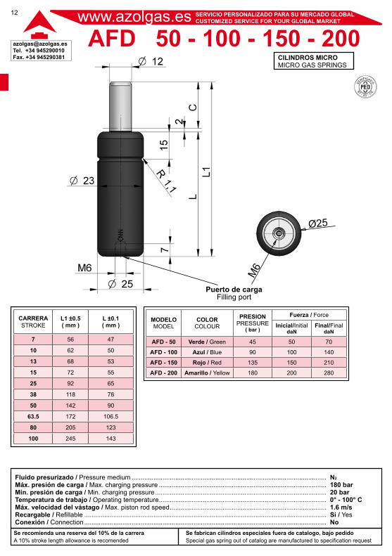
Se recomienda una reserva del 10% de la carreraA 10% stroke length allowance is recomended
Se fabrican cilindros especiales fuera de catalogo, bajo pedidoSpecial gas spring out of catalog are manufactured to specification request
Fluido presurizado / Pressure medium ...........................................................................................................Máx. presión de carga / Max. charging pressure ............................................................................................Mín. presión de carga / Min. charging pressure ..............................................................................................Temperatura de trabajo / Operating temperature ............................................................................................Máx. velocidad del vástago / Max. piston rod speed ......................................................................................Recargable / Refillable .....................................................................................................................................Conexión / Connection .....................................................................................................................................
CILINDROS MICROMICRO GAS SPRINGS
N2
180 bar20 bar0° - 100° C1.6 m/sSi / YesNo
AFD 50 - 100 - 150 - 200
Puerto de cargaFilling port
Ø25
M6
CARRERASTROKE
L1 ±0.5( mm )
L ±0.1( mm )
7 56 47
10 62 50
13 68 53
15 72 55
25 92 65
38 118 78
50 142 90
63.5 172 106.5
80 205 123
100 245 143
MODELOMODEL
COLORCOLOUR
PRESIONPRESSURE
( bar )
Fuerza / Force
Inicial/InitialdaN
Final/FinaldaN
AFD - 50 Verde / Green 45 50 70
AFD - 100 Azul / Blue 90 100 140
AFD - 150 Rojo / Red 135 150 210
AFD - 200 Amarillo / Yellow 180 200 280
[email protected]. +34 945290010Fax. +34 945290381
13
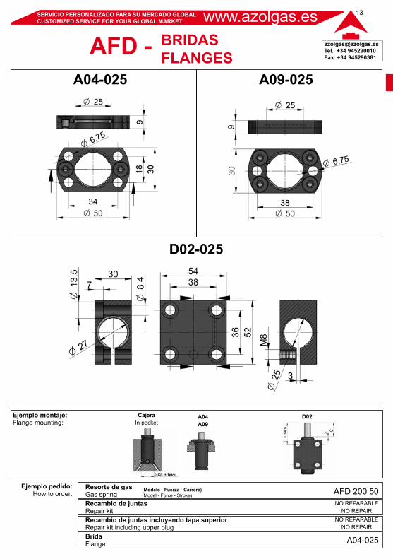
Ejemplo montaje:Flange mounting:
Ejemplo pedido:How to order:
Resorte de gasGas spring
BridaFlange
Recambio de juntasRepair kitRecambio de juntas incluyendo tapa superiorRepair kit including upper plug
D02CajeraIn pocket
www.azolgas.esSERVICIO PERSONALIZADO PARA SU MERCADO GLOBALCUSTOMIZED SERVICE FOR YOUR GLOBAL MARKET
(Modelo - Fuerza - Carrera)(Model - Force - Stroke)
A04A09
A09-025A04-025
D02-025
BRIDASFLANGESAFD -
A04-025
NO REPARABLENO REPAIR
NO REPARABLENO REPAIR
AFD 200 50
www.azolgas.es SERVICIO PERSONALIZADO PARA SU MERCADO GLOBALCUSTOMIZED SERVICE FOR YOUR GLOBAL MARKET
[email protected]. +34 945290010Fax. +34 945290381
14
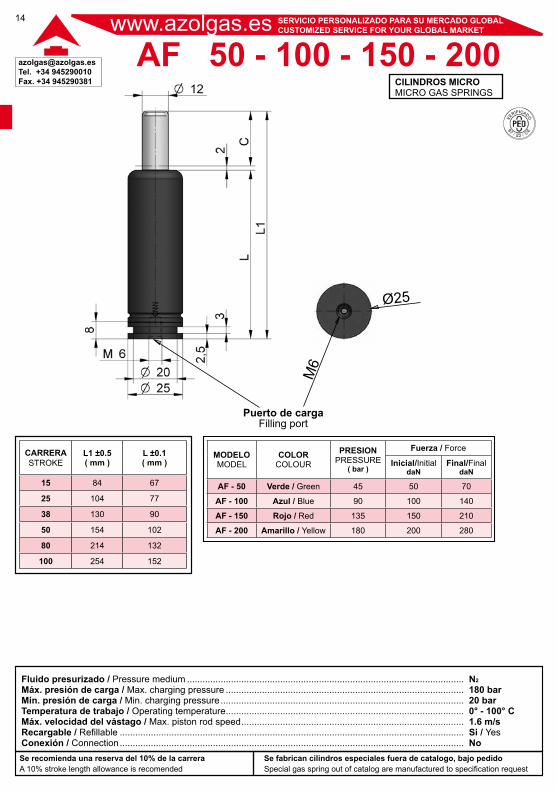
Se recomienda una reserva del 10% de la carreraA 10% stroke length allowance is recomended
Se fabrican cilindros especiales fuera de catalogo, bajo pedidoSpecial gas spring out of catalog are manufactured to specification request
Fluido presurizado / Pressure medium ...........................................................................................................Máx. presión de carga / Max. charging pressure ............................................................................................Mín. presión de carga / Min. charging pressure ..............................................................................................Temperatura de trabajo / Operating temperature ............................................................................................Máx. velocidad del vástago / Max. piston rod speed ......................................................................................Recargable / Refillable .....................................................................................................................................Conexión / Connection .....................................................................................................................................
CILINDROS MICROMICRO GAS SPRINGS
N2
180 bar20 bar0° - 100° C1.6 m/sSi / YesNo
AF 50 - 100 - 150 - 200
Puerto de cargaFilling port
Ø25M
6
CARRERASTROKE
L1 ±0.5( mm )
L ±0.1( mm )
15 84 67
25 104 77
38 130 90
50 154 102
80 214 132
100 254 152
MODELOMODEL
COLORCOLOUR
PRESIONPRESSURE
( bar )
Fuerza / Force
Inicial/InitialdaN
Final/FinaldaN
AF - 50 Verde / Green 45 50 70
AF - 100 Azul / Blue 90 100 140
AF - 150 Rojo / Red 135 150 210
AF - 200 Amarillo / Yellow 180 200 280
[email protected]. +34 945290010Fax. +34 945290381
15
Ejemplo montaje:Flange mounting:
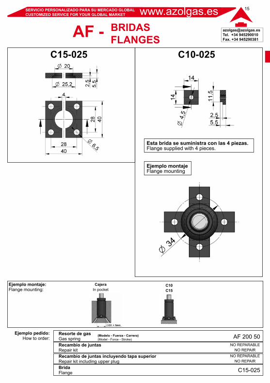
Ejemplo pedido:How to order:
Resorte de gasGas spring
BridaFlange
Recambio de juntasRepair kitRecambio de juntas incluyendo tapa superiorRepair kit including upper plug
CajeraIn pocket
www.azolgas.esSERVICIO PERSONALIZADO PARA SU MERCADO GLOBALCUSTOMIZED SERVICE FOR YOUR GLOBAL MARKET
(Modelo - Fuerza - Carrera)(Model - Force - Stroke)
C10-025C15-025
C10C15
BRIDASFLANGESAF -
C15-025
NO REPARABLENO REPAIR
NO REPARABLENO REPAIR
AF 200 50
Esta brida se suministra con las 4 piezas.Flange supplied with 4 pieces.
Ejemplo montajeFlange mounting
www.azolgas.es SERVICIO PERSONALIZADO PARA SU MERCADO GLOBALCUSTOMIZED SERVICE FOR YOUR GLOBAL MARKET
[email protected]. +34 945290010Fax. +34 945290381
16
Se recomienda una reserva del 10% de la carreraA 10% stroke length allowance is recomended
Se fabrican cilindros especiales fuera de catalogo, bajo pedidoSpecial gas spring out of catalog are manufactured to specification request
Fluido presurizado / Pressure medium ...........................................................................................................Máx. presión de carga / Max. charging pressure ............................................................................................Mín. presión de carga / Min. charging pressure ..............................................................................................Temperatura de trabajo / Operating temperature ............................................................................................Máx. velocidad del vástago / Max. piston rod speed ......................................................................................Recargable / Refillable .....................................................................................................................................Conexión / Connection .....................................................................................................................................
CILINDROS MICROMICRO GAS SPRINGS
N2
180 bar20 bar0° - 100° C1.6 m/sSi / YesNo
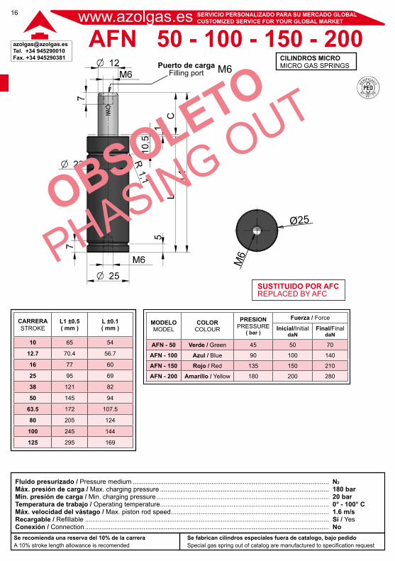
AFN 50 - 100 - 150 - 200Puerto de carga
Filling port
CARRERASTROKE
L1 ±0.5( mm )
L ±0.1( mm )
10 65 54
12.7 70.4 56.7
16 77 60
25 95 69
38 121 82
50 145 94
63.5 172 107.5
80 205 124
100 245 144
125 295 169
MODELOMODEL
COLORCOLOUR
PRESIONPRESSURE
( bar )
Fuerza / Force
Inicial/InitialdaN
Final/FinaldaN
AFN - 50 Verde / Green 45 50 70
AFN - 100 Azul / Blue 90 100 140
AFN - 150 Rojo / Red 135 150 210
AFN - 200 Amarillo / Yellow 180 200 280
M6
M6
Ø25
SUSTITUIDO POR AFCREPLACED BY AFC

[email protected]. +34 945290010Fax. +34 945290381
17
Ejemplo montaje:Flange mounting:
Ejemplo pedido:How to order:
Resorte de gasGas spring
BridaFlange
Recambio de juntasRepair kitRecambio de juntas incluyendo tapa superiorRepair kit including upper plug
D02CajeraIn pocket
www.azolgas.esSERVICIO PERSONALIZADO PARA SU MERCADO GLOBALCUSTOMIZED SERVICE FOR YOUR GLOBAL MARKET
(Modelo - Fuerza - Carrera)(Model - Force - Stroke)
A04A09
KIT+PLUG AFN 200 50(número de serie/serial number)
KIT AFN 200 50(número de serie/serial number)
BRIDASFLANGESAFN -
A04-025
AFN 200 50
D02-025
A09-025A04-025
www.azolgas.es SERVICIO PERSONALIZADO PARA SU MERCADO GLOBALCUSTOMIZED SERVICE FOR YOUR GLOBAL MARKET
[email protected]. +34 945290010Fax. +34 945290381
18
Se recomienda una reserva del 10% de la carreraA 10% stroke length allowance is recomended
Se fabrican cilindros especiales fuera de catalogo, bajo pedidoSpecial gas spring out of catalog are manufactured to specification request
Fluido presurizado / Pressure medium ...........................................................................................................Máx. presión de carga / Max. charging pressure ............................................................................................Mín. presión de carga / Min. charging pressure ..............................................................................................Temperatura de trabajo / Operating temperature ............................................................................................Máx. velocidad del vástago / Max. piston rod speed ......................................................................................Recargable / Refillable .....................................................................................................................................Conexión / Connection .....................................................................................................................................
CILINDROS MICROMICRO GAS SPRINGS
N2
180 bar20 bar0° - 100° C1.6 m/sSi / YesNo
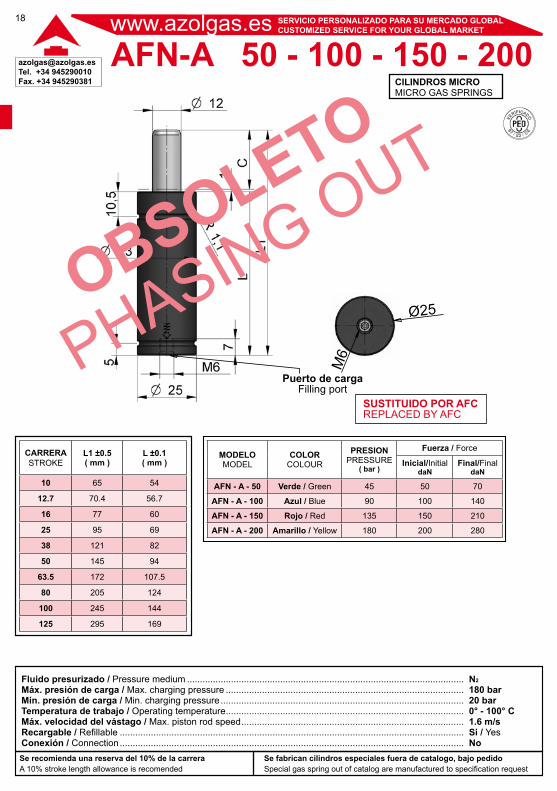
AFN-A 50 - 100 - 150 - 200
Puerto de cargaFilling port
CARRERASTROKE
L1 ±0.5( mm )
L ±0.1( mm )
10 65 54
12.7 70.4 56.7
16 77 60
25 95 69
38 121 82
50 145 94
63.5 172 107.5
80 205 124
100 245 144
125 295 169
MODELOMODEL
COLORCOLOUR
PRESIONPRESSURE
( bar )
Fuerza / Force
Inicial/InitialdaN
Final/FinaldaN
AFN - A - 50 Verde / Green 45 50 70
AFN - A - 100 Azul / Blue 90 100 140
AFN - A - 150 Rojo / Red 135 150 210
AFN - A - 200 Amarillo / Yellow 180 200 280
M6
Ø25
SUSTITUIDO POR AFCREPLACED BY AFC
[email protected]. +34 945290010Fax. +34 945290381
19
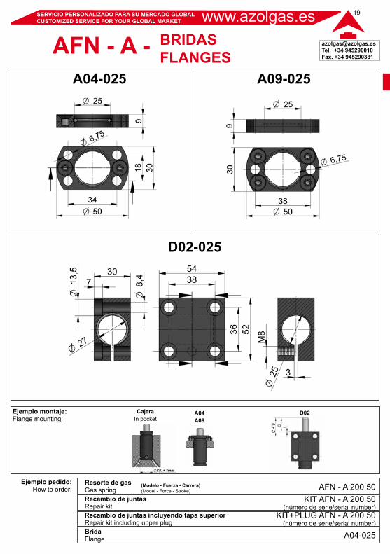
Ejemplo montaje:Flange mounting:
Ejemplo pedido:How to order:
Resorte de gasGas spring
BridaFlange
Recambio de juntasRepair kitRecambio de juntas incluyendo tapa superiorRepair kit including upper plug
D02CajeraIn pocket
www.azolgas.esSERVICIO PERSONALIZADO PARA SU MERCADO GLOBALCUSTOMIZED SERVICE FOR YOUR GLOBAL MARKET
(Modelo - Fuerza - Carrera)(Model - Force - Stroke)
KIT+PLUG AFN - A 200 50(número de serie/serial number)
KIT AFN - A 200 50(número de serie/serial number)
BRIDASFLANGESAFN - A -
A04-025
AFN - A 200 50
D02-025
A09-025A04-025
A04A09
www.azolgas.es SERVICIO PERSONALIZADO PARA SU MERCADO GLOBALCUSTOMIZED SERVICE FOR YOUR GLOBAL MARKET
[email protected]. +34 945290010Fax. +34 945290381
20
Se recomienda una reserva del 10% de la carreraA 10% stroke length allowance is recomended
Se fabrican cilindros especiales fuera de catalogo, bajo pedidoSpecial gas spring out of catalog are manufactured to specification request
Fluido presurizado / Pressure medium ...........................................................................................................Máx. presión de carga / Max. charging pressure ............................................................................................Mín. presión de carga / Min. charging pressure ..............................................................................................Temperatura de trabajo / Operating temperature ............................................................................................Máx. velocidad del vástago / Max. piston rod speed ......................................................................................Recargable / Refillable .....................................................................................................................................Conexión / Connection .....................................................................................................................................
CILINDROS MICROMICRO GAS SPRINGS
N2
180 bar20 bar0° - 100° C1.6 m/sSi / YesNo
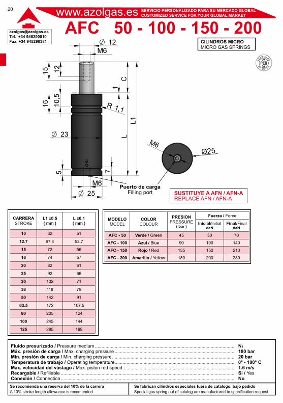
AFC 50 - 100 - 150 - 200
Puerto de cargaFilling port
CARRERASTROKE
L1 ±0.5( mm )
L ±0.1( mm )
10 62 51
12.7 67.4 53.7
15 72 56
16 74 57
20 82 61
25 92 66
30 102 71
38 118 79
50 142 91
63.5 172 107.5
80 205 124
100 245 144
125 295 169
Ø25
SUSTITUYE A AFN / AFN-AREPLACE AFN / AFN-A
MODELOMODEL
COLORCOLOUR
PRESIONPRESSURE
( bar )
Fuerza / Force
Inicial/InitialdaN
Final/FinaldaN
AFC - 50 Verde / Green 45 50 70
AFC - 100 Azul / Blue 90 100 140
AFC - 150 Rojo / Red 135 150 210
AFC - 200 Amarillo / Yellow 180 200 280
[email protected]. +34 945290010Fax. +34 945290381
21
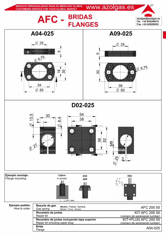
Ejemplo montaje:Flange mounting:
Ejemplo pedido:How to order:
Resorte de gasGas spring
BridaFlange
Recambio de juntasRepair kitRecambio de juntas incluyendo tapa superiorRepair kit including upper plug
D02CajeraIn pocket
www.azolgas.esSERVICIO PERSONALIZADO PARA SU MERCADO GLOBALCUSTOMIZED SERVICE FOR YOUR GLOBAL MARKET
(Modelo - Fuerza - Carrera)(Model - Force - Stroke)
KIT+PLUG AFC 200 50(número de serie/serial number)
KIT AFC 200 50(número de serie/serial number)
BRIDASFLANGESAFC -
A04-025
AFC 200 50
D02-025
A09-025A04-025
A04A09
www.azolgas.es SERVICIO PERSONALIZADO PARA SU MERCADO GLOBALCUSTOMIZED SERVICE FOR YOUR GLOBAL MARKET
[email protected]. +34 945290010Fax. +34 945290381
22
Se recomienda una reserva del 10% de la carreraA 10% stroke length allowance is recomended
Se fabrican cilindros especiales fuera de catalogo, bajo pedidoSpecial gas spring out of catalog are manufactured to specification request
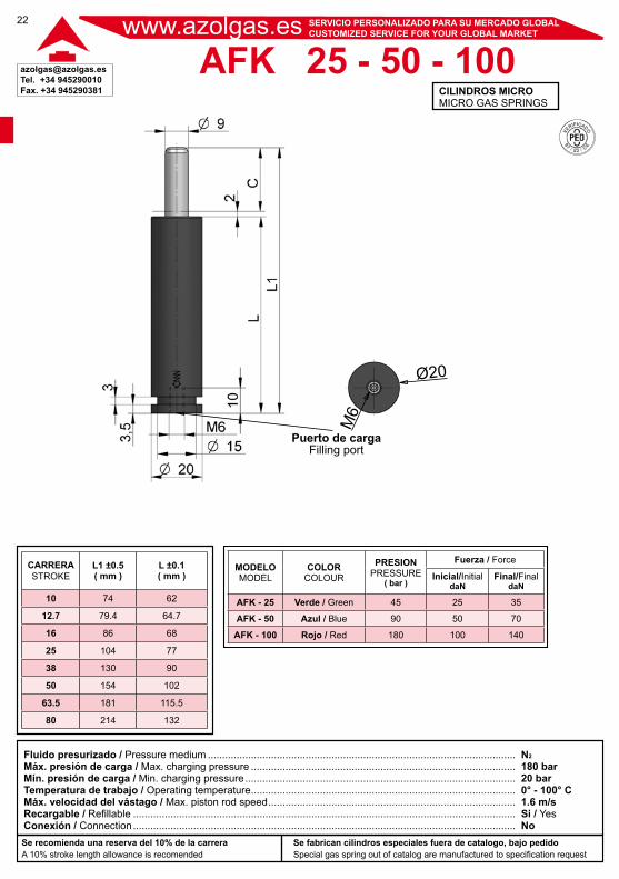
Fluido presurizado / Pressure medium ...........................................................................................................Máx. presión de carga / Max. charging pressure ............................................................................................Mín. presión de carga / Min. charging pressure ..............................................................................................Temperatura de trabajo / Operating temperature ............................................................................................Máx. velocidad del vástago / Max. piston rod speed ......................................................................................Recargable / Refillable .....................................................................................................................................Conexión / Connection .....................................................................................................................................
CILINDROS MICROMICRO GAS SPRINGS
N2
180 bar20 bar0° - 100° C1.6 m/sSi / YesNo
AFK 25 - 50 - 100
Puerto de cargaFilling port
CARRERASTROKE
L1 ±0.5( mm )
L ±0.1( mm )
10 74 62
12.7 79.4 64.7
16 86 68
25 104 77
38 130 90
50 154 102
63.5 181 115.5
80 214 132
Ø20
MODELOMODEL
COLORCOLOUR
PRESIONPRESSURE
( bar )
Fuerza / Force
Inicial/InitialdaN
Final/FinaldaN
AFK - 25 Verde / Green 45 25 35
AFK - 50 Azul / Blue 90 50 70
AFK - 100 Rojo / Red 180 100 140
M6
[email protected]. +34 945290010Fax. +34 945290381
23
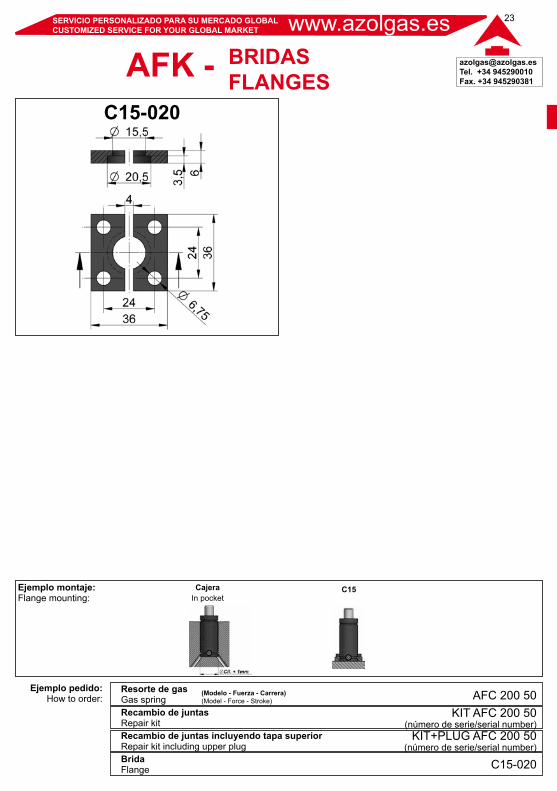
Ejemplo montaje:Flange mounting:
Ejemplo pedido:How to order:
Resorte de gasGas spring
BridaFlange
Recambio de juntasRepair kitRecambio de juntas incluyendo tapa superiorRepair kit including upper plug
CajeraIn pocket
www.azolgas.esSERVICIO PERSONALIZADO PARA SU MERCADO GLOBALCUSTOMIZED SERVICE FOR YOUR GLOBAL MARKET
(Modelo - Fuerza - Carrera)(Model - Force - Stroke)
C15
C15-020
KIT+PLUG AFC 200 50(número de serie/serial number)
KIT AFC 200 50(número de serie/serial number)
BRIDASFLANGESAFK -
C15-020
AFC 200 50

www.azolgas.es SERVICIO PERSONALIZADO PARA SU MERCADO GLOBALCUSTOMIZED SERVICE FOR YOUR GLOBAL MARKET
[email protected]. +34 945290010Fax. +34 945290381
24
NOTAS / NOTES