Embed Size (px)
Citation preview
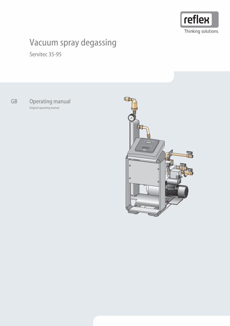
Vacuum spray degassing 01.04.2014
Servitec 35-95
GB
Operating manual Original operating manual

Contents
Vacuum spray degassing — 01.04.2014 English — 3
English
Contents
1 Notes on the operating manual .................................................................................................................................................... 5
2 Liability and guarantee .................................................................................................................................................................. 5
3 Safety ............................................................................................................................................................................................... 6 3.1 Explanation of symbols ........................................................................................................................................................................ 6
3.1.1 Symbols and notes used ................................................................................................................................................... 6
3.1.2 Safety symbols used .......................................................................................................................................................... 6
3.2 Personnel requirements ...................................................................................................................................................................... 7
3.3 Personal protective equipment .......................................................................................................................................................... 7
3.4 Intended use .......................................................................................................................................................................................... 7
3.5 Inadmissible operating conditions..................................................................................................................................................... 7
3.6 Residual risks ......................................................................................................................................................................................... 8
4 Description of the device ............................................................................................................................................................... 9 4.1 Description ............................................................................................................................................................................................. 9
4.2 Overview ................................................................................................................................................................................................ 9
4.3 Identification ....................................................................................................................................................................................... 10
4.4 Function ............................................................................................................................................................................................... 11
4.5 Scope of delivery ................................................................................................................................................................................. 14
4.6 Optional equipment and accessories .............................................................................................................................................. 14
5 Technical data ............................................................................................................................................................................... 15
6 Installation ..................................................................................................................................................................................... 18 6.1 Installation conditions ....................................................................................................................................................................... 19
6.1.1 Incoming inspection ....................................................................................................................................................... 19
6.2 Preparatory work ................................................................................................................................................................................ 19
6.3 Execution .............................................................................................................................................................................................. 20
6.3.1 Fitting the add-on components .................................................................................................................................... 20
6.3.2 Floor/wall installation ..................................................................................................................................................... 21
6.3.3 Hydraulic connection ...................................................................................................................................................... 22
6.4 Switching and make-up variants ...................................................................................................................................................... 25
6.4.1 Pressure-dependent "Magcontrol" make-up mode .................................................................................................. 25
6.4.2 Level dependent "Levelcontrol" make-up mode ....................................................................................................... 26
6.5 Electrical connection .......................................................................................................................................................................... 27
6.5.1 Terminal diagram ............................................................................................................................................................ 28
6.5.2 RS-485 interface .............................................................................................................................................................. 30
6.6 Installation and commissioning certificate ..................................................................................................................................... 31
7 Commissioning ............................................................................................................................................................................. 32 7.1 Checking the requirements for commissioning ............................................................................................................................. 32
7.2 Setting the minimum operating pressure for Magcontrol ........................................................................................................... 32
7.3 Controller ............................................................................................................................................................................................. 33
7.3.1 Operator panel ................................................................................................................................................................. 33
7.4 Modifying the controller's start routine .......................................................................................................................................... 34
7.5 Filling the device with water and venting ...................................................................................................................................... 35
7.6 Vacuum test ......................................................................................................................................................................................... 36
7.7 Filling system with device ................................................................................................................................................................. 37
7.8 Parametrising the controller in the Customer menu .................................................................................................................... 38
7.9 Starting Automatic mode .................................................................................................................................................................. 41
8 Operation ....................................................................................................................................................................................... 42 8.1 Operating modes ................................................................................................................................................................................ 42
8.1.1 Automatic mode .............................................................................................................................................................. 42
Contents
4 — English Vacuum spray degassing — 01.04.2014
8.1.2 Manual mode ................................................................................................................................................................... 43
8.1.3 Stop mode ........................................................................................................................................................................ 43
8.1.4 Summer operation .......................................................................................................................................................... 44
8.1.5 Restarting ......................................................................................................................................................................... 44
8.2 Controller ............................................................................................................................................................................................. 44
8.2.1 Customer menu ............................................................................................................................................................... 44
8.2.2 Service menu .................................................................................................................................................................... 44
8.2.3 Default settings ............................................................................................................................................................... 45
8.2.4 Messages .......................................................................................................................................................................... 46
9 Maintenance ................................................................................................................................................................................. 49 9.1 Cleaning ............................................................................................................................................................................................... 50
9.1.1 Cleaning the dirt trap ...................................................................................................................................................... 50
9.2 Inspecting system degassing and make-up degassing ................................................................................................................ 50
9.3 Maintenance certificate ..................................................................................................................................................................... 51
9.4 Inspection ............................................................................................................................................................................................ 52
9.4.1 Pressure-bearing components ...................................................................................................................................... 52
9.4.2 Inspection prior to commissioning ............................................................................................................................... 52
9.4.3 Inspection intervals ......................................................................................................................................................... 52
10 Disassembly .................................................................................................................................................................................. 53
11 Annex ............................................................................................................................................................................................ 54 11.1 Reflex Customer Service .................................................................................................................................................................... 54
11.2 Conformity and standards ................................................................................................................................................................. 55
11.3 Certificate No. of the design type examination ............................................................................................................................. 56
11.4 Guarantee ............................................................................................................................................................................................ 57
11.5 Glossary ................................................................................................................................................................................................ 57
Vacuum spray degassing
01.04.2014
Notes on the operating manual
Vacuum spray degassing — 01.04.2014 English — 5
1 Notes on the operating manual This operating manual is an important aid for the safe and reliable function of the device.
The operating manual is intended to:
• Avert dangers to personnel.
• Understand the device.
• Obtain optimal functioning.
• Early identify and rectify problems.
• Avoid faults caused by improper use.
• Prevent repair costs and downtimes.
• Increase reliability and service life.
• Prevent damage to the environment.
Reflex Winkelmann GmbH cannot accept any liability for damage caused by ignoring this operating manual. In addition to this operating manual, you must comply with national legislation and regulations in the country of use (accident prevention, environment protection, save and proper work, etc.).
This operating manual describes the device with basic equipment for degassing and interfaces for optional equipment with additional functions. For optional equipment and accessories, see chapter 4.6 "Optional equipment and accessories" on page 14 .
Notice! Every person installing this equipment or performing any other work at the equipment is required to carefully read this operating manual prior to commencing work and to comply with its instructions. The manual is to be provided to the product operator and must be stored near the product for access at any time.
2 Liability and guarantee The product is manufactured to the latest engineering standards and acknowledged safety regulations. Nevertheless, risk of injury and death for the user and other parties and damage to the system and other property can arise from its use.
Modifications of the device such as changes of the hydraulic system or interference with the interconnection are strictly prohibited.
The liability and guarantee of the manufacturer are excluded when the malfunction can be traced back to one or more of the following causes:
• Improper use of the device.
• Improper commissioning, operation, maintenance, servicing, repair, and installation of the device.
• Ignoring the safety notes in this operating manual.
• Device operation with defective or improperly installed safety and/or protective equipment.
• Failure to perform maintenance and inspection work at due times.
• Use of unauthorised replacement parts and accessories.
The precondition for any guarantee claims is the proper installation and commissioning of the device.
Notice! Have the Reflex Customer Service carry out commissioning and the annual maintenance, see chapter 11.1 "Reflex Customer Service" on page 54 .
Safety
6 — English Vacuum spray degassing — 01.04.2014
3 Safety 3.1 Explanation of symbols
3.1.1 Symbols and notes used
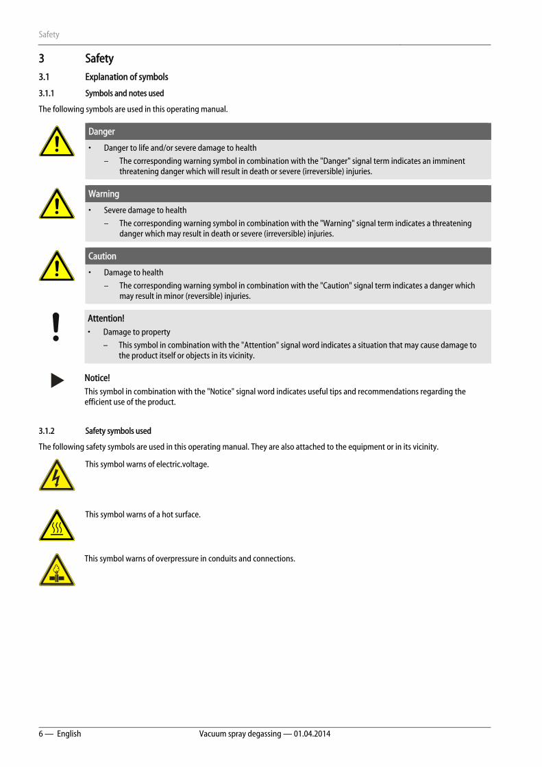
The following symbols are used in this operating manual.
Danger
• Danger to life and/or severe damage to health
– The corresponding warning symbol in combination with the "Danger" signal term indicates an imminent threatening danger which will result in death or severe (irreversible) injuries.
Warning
• Severe damage to health
– The corresponding warning symbol in combination with the "Warning" signal term indicates a threatening danger which may result in death or severe (irreversible) injuries.
Caution
• Damage to health
– The corresponding warning symbol in combination with the "Caution" signal term indicates a danger which may result in minor (reversible) injuries.
Attention! • Damage to property
– This symbol in combination with the "Attention" signal word indicates a situation that may cause damage to the product itself or objects in its vicinity.
Notice! This symbol in combination with the "Notice" signal word indicates useful tips and recommendations regarding the efficient use of the product.
3.1.2 Safety symbols used
The following safety symbols are used in this operating manual. They are also attached to the equipment or in its vicinity.
This symbol warns of electric.voltage.
This symbol warns of a hot surface.
This symbol warns of overpressure in conduits and connections.
Safety
Vacuum spray degassing — 01.04.2014 English — 7
3.2 Personnel requirements
Only specialist personnel or specifically trained personnel may install and operate the equipment.
The electric connections and the wiring of the device must be executed by a specialist in accordance with all applicable national and local regulations.
3.3 Personal protective equipment
When working at the system, wear the stipulated personal equipment such as hearing and eye protection, safety boots, helmet, protective clothing, protective gloves.
See the national regulation of your country for personal protective equipment required.
3.4 Intended use
• The device is used in stationary heating and cooling circuits. The devices may be used only in systems that are sealed against corrosion and with the following water types:
• Non-corrosive
• Chemically non-aggressive
• Non-toxic
• The ingress of atmospheric oxygen by permeation into the entire heating and cooling water system, make-up water and similar must be reliably minimised during operation.
Notice!
The quality of the make-up water must comply with the applicable standards such as VDI 2035.
3.5 Inadmissible operating conditions
The devices are not suited for the following conditions.
• In mobile system operation
• For outdoors operation
• For the use with mineral oils
• For the use with flammable media
• For the use with distilled water
Notice!
Changes to the hydraulic system or interference with the interconnection are strictly prohibited.
Safety
8 — English Vacuum spray degassing — 01.04.2014
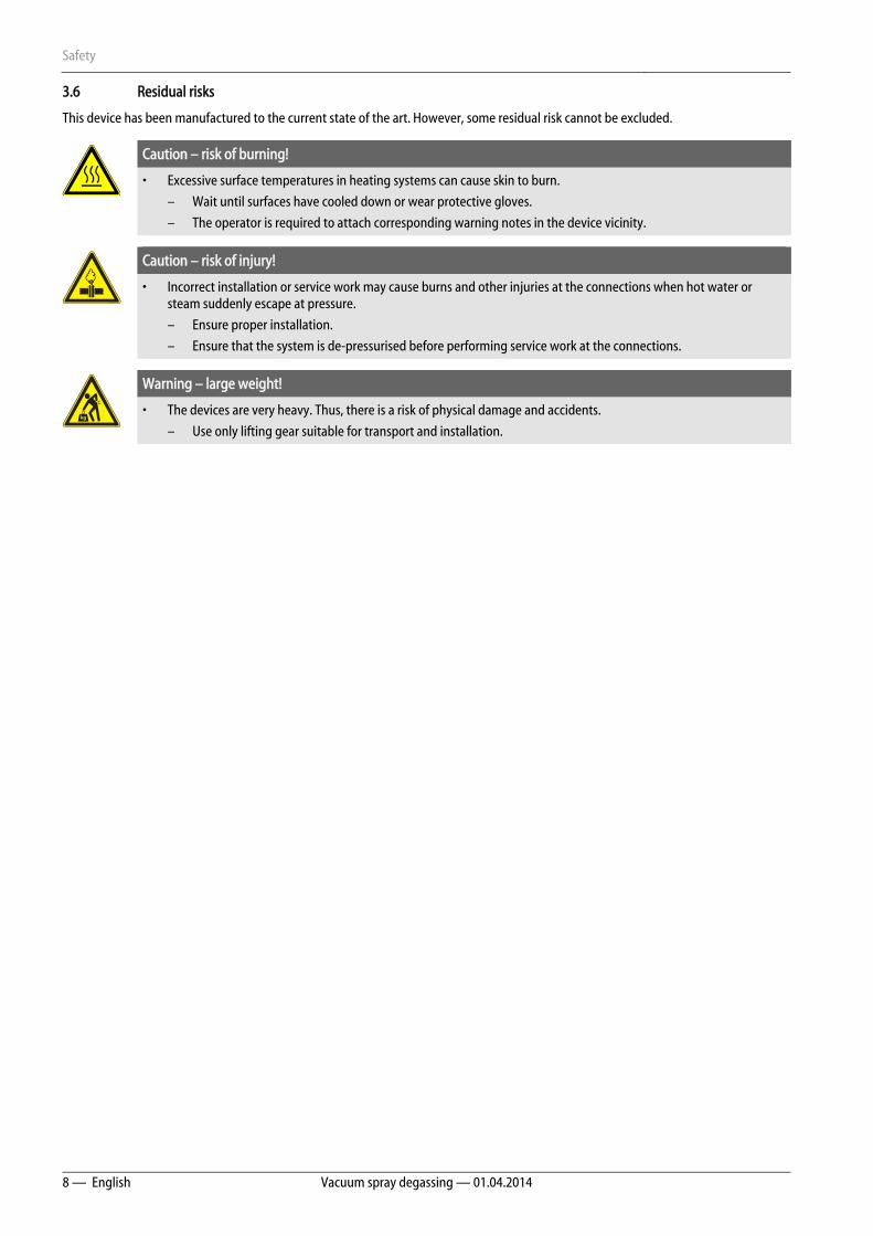
3.6 Residual risks
This device has been manufactured to the current state of the art. However, some residual risk cannot be excluded.
Caution – risk of burning!
• Excessive surface temperatures in heating systems can cause skin to burn.
– Wait until surfaces have cooled down or wear protective gloves.
– The operator is required to attach corresponding warning notes in the device vicinity.
Caution – risk of injury!
• Incorrect installation or service work may cause burns and other injuries at the connections when hot water or steam suddenly escape at pressure.
– Ensure proper installation.
– Ensure that the system is de-pressurised before performing service work at the connections.
Warning – large weight!
• The devices are very heavy. Thus, there is a risk of physical damage and accidents.
– Use only lifting gear suitable for transport and installation.
Description of the device
Vacuum spray degassing — 01.04.2014 English — 9
4 Description of the device 4.1 Description
The device is a degassing and make-up station. Its main areas of application are heating and cooling circuits and systems in which interruptions of operations due to dissolved or free gases. The device provides the following safety features:
• No direct intake of air thanks to a regulation of the pressure maintenance with automatic make-up.
• No circulation issues caused by free bubbles in the circuit water.
• Reduced corrosion damage due to oxygen removal from fill and make-up water.
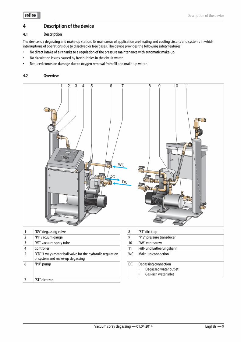
4.2 Overview
1 "DV" degassing valve 8 "ST" dirt trap 2 "PI" vacuum gauge 9 "PIS" pressure transducer 3 "VT" vacuum spray tube 10 "AV" vent screw 4 Controller 11 Füll- und Entleerungshahn 5 "CD" 3-ways motor ball valve for the hydraulic regulation
of system and make-up degassing WC Make-up connection
6 "PU" pump DC Degassing connection • Degassed water outlet • Gas-rich water inlet
7 "ST" dirt trap
WC
DCDC
1 2 43 5 6 7 8 9 10 11
Description of the device
10 — English Vacuum spray degassing — 01.04.2014
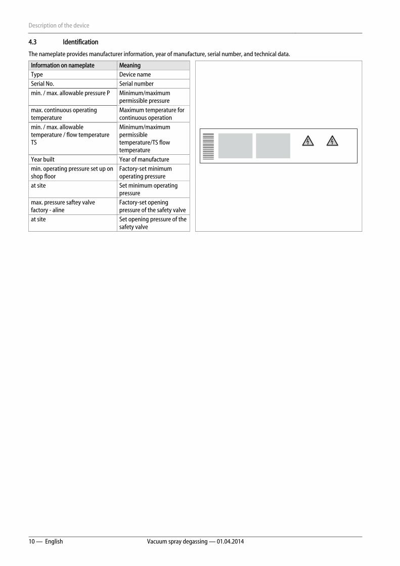
4.3 Identification
The nameplate provides manufacturer information, year of manufacture, serial number, and technical data.
Information on nameplate Meaning Type Device name Serial No. Serial number min. / max. allowable pressure P Minimum/maximum
permissible pressure
max. continuous operating temperature
Maximum temperature for continuous operation
min. / max. allowable temperature / flow temperature TS
Minimum/maximum permissible temperature/TS flow temperature
Year built Year of manufacture min. operating pressure set up on shop floor
Factory-set minimum operating pressure
at site Set minimum operating pressure
max. pressure saftey valve factory - aline
Factory-set opening pressure of the safety valve
at site Set opening pressure of the safety valve

Description of the device
Vacuum spray degassing — 01.04.2014 English — 11
4.4 Function
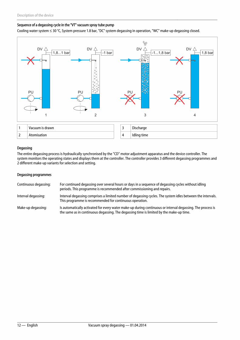
The device is suited only for the system water and the make-up water. It removes up to 90 percent of the dissolved gases from the water. The degassing operation uses timer-controlled cycles. A cycle comprises the following phases:
• Drawing the vacuum
– The "PU“ pump draws a vacuum. The "DC" inlet to the "VT" vacuum spray tube remains closed.
• Atomisation
– The inlet to the "VT" vacuum spray tube is opened. Depending on the actual demand, a partial flow of the gas-rich system water of the "V" main volume flow and the make-up water are introduced through the "DC" or "WC" lines of the device and finely atomised in the "PU" vacuum spray tube. The large surface of the atomised water and the gas saturation headway to the vacuum result in a degassing of the water. Via the "PU" pump, the degassed water is returned from the "VT" vacuum spray tube into the system where it is again ready to dissolve gases.
• Discharge
– The "PU" pump shuts off. The system continues to inject and degas water in the "VT" vacuum spray tube. The water level in the "VT" spray tube rises. The gases separated from the water are discharged via the "DV" degassing valve.
• Idling time
– When the gas has been discharged, the device will remain in idle until the next cycle is started.
Description of the device
12 — English Vacuum spray degassing — 01.04.2014
Sequence of a degassing cycle in the "VT" vacuum spray tube pump
Cooling water system ≤ 30 °C, System pressure 1.8 bar, "DC" system degassing in operation, "WC" make-up degassing closed.
1 Vacuum is drawn 3 Discharge
2 Atomisation 4 Idling time
Degassing
The entire degassing process is hydraulically synchronised by the "CD" motor adjustment apparatus and the device controller. The system monitors the operating states and displays them at the controller. The controller provides 3 different degassing programmes and 2 different make-up variants for selection and setting.
Degassing programmes
Continuous degassing: For continued degassing over several hours or days in a sequence of degassing cycles without idling periods. This programme is recommended after commissioning and repairs.
Interval degassing: Interval degassing comprises a limited number of degassing cycles. The system idles between the intervals. This programme is recommended for continuous operation.
Make-up degassing: Is automatically activated for every water make-up during continuous or interval degassing. The process is the same as in continuous degassing. The degassing time is limited by the make-up time.
DV1,8 bar
PU
DV-1...1,8 bar
PU
DV-1 bar
PU
DV1,8...1 bar
PU
1 2 3 4

Description of the device
Vacuum spray degassing — 01.04.2014 English — 13
Make-up variants
There are two make-up variants. Both are monitored via the make-up time and the make-up cycles.
1 Signal line from the "LIS" level sensor for the "Levelcontrol" make-up variant
5 "WC" make-up line
2 Signal line from the "PIS" pressure transducer for "Magcontrol" make-up variant
6 Device
3 "DC" degassing line (degassed water) 7 For optional equipment and accessories, see chapter 4.6 "Optional equipment and accessories" on page 14
4 "DC" degassing line (gas-rich water)
Magcontrol: For systems with diaphragm-type pressure expansion tank.
– Using the integrated "PIS" pressure transducer, the system registers and monitors the pressure in the heating or cooling system. The make-up degassing process is activated as soon as the pressure drops below the calculated filling pressure.
Levelcontrol: For systems with pressure maintaining stations.
– Depending on the level in the tank for the "LIS" pressure maintenance station, water is added directly into the station. The make-up function can be triggered by an external 230 V ~ signal.
LIS
PIS
WCDC
M
V
CD
CD
PU
M
1 2 3 4 5 6 7
Description of the device
14 — English Vacuum spray degassing — 01.04.2014
4.5 Scope of delivery
The scope of delivery is described in the shipping document and the content is shown on the packaging.
Immediately after receipt of the goods, please check the shipment for completeness and damage. Please notify us immediately of any transport damage.
Basic degassing equipment:
• Device controller
• "DV" degassing valve, box-packaged.
• Plastic sleeve with operating manual and electric wiring diagram (attached to the device).
The device is pre-assembled and shipped on a pallet.
4.6 Optional equipment and accessories
The following optional equipment and accessories are available for this device:
• Fillset for make-up with water.
– Fillset with integrated backflow preventer, water meter, dirt trap, and locking mechanisms for the "WC" make-up line.
• Fillset Impulse with FQIRA+ contact water meter for make-up with water.
– If the Fillset Impulse with FQIRA+ contact water meter is installed in the make-up line, you can regulate the entire make-up quantity and the soft water capacity of Fillsoft softening systems. The operational reliability of the device is assured and prevents the automatic make-up during major water loss or small leaks.
• Fillsoft for softening the make-up water from the public water network.
– Fillsoft is installed between Fillset and the device. The device controller evaluates the make-up quantities and signals a required replacement of the softening cartridges.
• Enhancements for the device controller.
• Use the RS-485 interface to retrieve various data from the controller and to communicate with control centres or other devices.,see chapter 6.5.2.1 "Connecting the RS-485 interface" on page 30 . You need the following items for the communication of the RS-485 interface with control centres or other devices:
– Bus modules for the communication with control centres
– Lonworks Digital
– Lonworks
– Profibus-DP
– Ethernet
– I/O module for standard communication
• Reflexomat for system with pressure-maintaining stations.
– The Reflexomat and device combination is preferred. Despite the degassed network, Reflexomat assured an extremely elastic operation at constant pressure. Make-up is executed depending on the water level measured with the "LIS" level sensor of the Reflexomat in the expansion tank of the pressure maintaining station. For a make-up request, the Reflexomat controller activates a 230 V signal to the device controller.
• Gas discharge measurement for an optimised degassing operation.
Notice! Separate installation, operation, and maintenance instructions are supplied with the accessories and optional equipment.

Technical data
Vacuum spray degassing — 01.04.2014 English — 15
5 Technical data
1 "DV" degassing valve 4 "PU" pump 2 "PI" vacuum gauge WC Make-up line 3 "VT" vacuum spray tube DC Degassing connection
• Degassed water outlet • Gas-rich water inlet
Servitec 35 Servitec 60 Servitec 60 gl Servitec 75 Servitec 95 Part No. 8829000 8829100 8828100 8829200 8829300 Width 620 mm 685 mm 685 mm 600 mm 600 mm Height 1030 mm 1215 mm 1215 mm 1215 mm 1215 mm Depth 440 mm 525 mm 525 mm 525 mm 525 mm Weight 28 kg 34 kg 34 kg 34 kg 40 kg
Permissible gauge working pressure
Depending on the customer-specific system, see nameplate
Depending on the customer-specific system, see nameplate
Depending on the customer-specific system, see nameplate
Depending on the customer-specific system, see nameplate
Depending on the customer-specific system, see nameplate
Minimum flow pressure 1.3 bar 1.3 bar 1.3 bar 1.3 bar 1.3 bar Permissible operating temperature ˃ 0 – 70 °C ˃ 0 – 70 °C ˃ 0 – 70 °C ˃ 0 – 70 °C ˃ 0 – 70 °C
Permissible ambient temperature ˃ 0 - 45 °C ˃ 0 - 45 °C ˃ 0 - 45 °C ˃ 0 - 45 °C ˃ 0 - 45 °C Spray tube nominal volume 5 Litres 5 Litres 5 Litres 5 Litres 5 Litres Degree of discharge, dissolved gases
≤ 90 % ≤ 90 % ≤ 90 % ≤ 90 % ≤ 90 %
Degree of discharge, free gases 100 % 100 % 100 % 100 % 100 % Noise level 55 db 55 db 55 db 55 db 55 db
WC
DCDC
21 3 4

Technical data
16 — English Vacuum spray degassing — 01.04.2014
Electrical power supply Servitec 35 Servitec 60 Servitec 60 gl Servitec 75 Servitec 95 Degree of protection IP 54 54 54 54 54 Output 700 W 1100 W 1100 W 1100 W 1100 W Fusing 10 A 10 A 10 A 10 A 10 A Voltage 230 V 230 V 230 V 230 V 230 V Frequency 50 Hz 50 Hz 50 Hz 50 Hz 50 Hz Electrical power supply, controller Servitec 35 Servitec 60 Servitec 60 gl Servitec 75 Servitec 95 Voltage 230 V 230 V 230 V 230 V 230 V Fusing 4 A 4 A 4 A 4 A 4 A Individual protection 500 mA 500 mA 500 mA 500 mA 500 mA Servitec 35 Servitec 60 Servitec 60 gl Servitec 75 Servitec 95 System volume* Va 100 220 m3 220 m3 - 220 m3 220 m3 System volume* Va 50 - - 50 m3 - - Minimum flow volume V 0.7 m3 / h 1.1 m3 / h 1.1 m3 / h 1.1 m3 / h 1.1 m3 / h Working pressure 0.5 – 2.5 bar 0.5 – 4.5 bar 0.5 – 4.5 bar 0.5 – 5.4 bar 0.5 – 7.2 bar Make-up output 0.55 m3 / h 0.55 m3 / h 0.55 m3 / h 0.55 m3 / h 0.55 m3 / h Connector, "DC" degassing line to device, internal thread (IG)
IG ½ " IG ½ " IG ½ " IG ½ " IG ½ "
Connector, "DC" degassing line to system, internal thread (IG)
IG 1 " IG 1 " IG 1 " IG 1 " IG 1 "
Connector for "WC" make-up line, internal thread (IG)
IG ½ " IG ½ " IG ½ " IG ½ " IG ½ "
* Va 100 = 100 % water
Va 50/50 = water with anti-freeze portion to 50%
Technical data
Vacuum spray degassing — 01.04.2014 English — 17
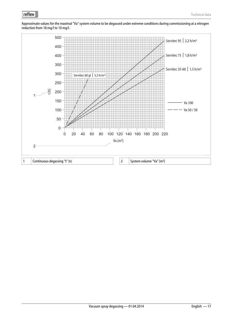
Approximate values for the maximal "Va" system volume to be degassed under extreme conditions during commissioning at a nitrogen reduction from 18 mg/l to 10 mg/l.
1 Continuous degassing "t" [h] 2 System volume "Va" [m3]
0
50
100
150
200
250
300
350
400
450
500
Va 100
Va 50 / 50
0 20 40 60 80 100 120 140 160 180 200 220
Servitec 60 gl 5,3 h/m³│
Servitec 95 2,2 h/m³│
Servitec 75 1,8 h/m³│
Servitec 35-60 1,5 h/m³│
t [h
]
Va [m³]
2
1
Installation
18 — English Vacuum spray degassing — 01.04.2014
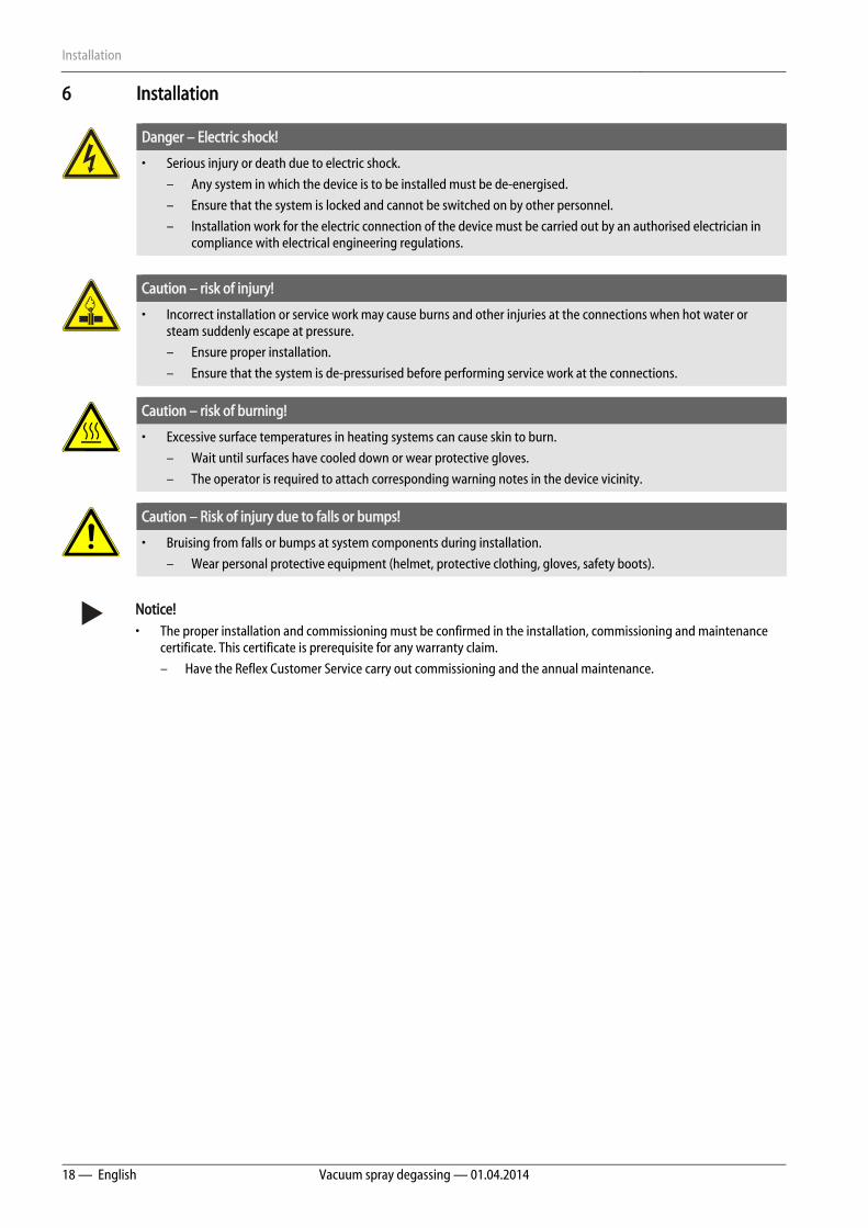
6 Installation
Danger – Electric shock!
• Serious injury or death due to electric shock.
– Any system in which the device is to be installed must be de-energised.
– Ensure that the system is locked and cannot be switched on by other personnel.
– Installation work for the electric connection of the device must be carried out by an authorised electrician in compliance with electrical engineering regulations.
Caution – risk of injury!
• Incorrect installation or service work may cause burns and other injuries at the connections when hot water or steam suddenly escape at pressure.
– Ensure proper installation.
– Ensure that the system is de-pressurised before performing service work at the connections.
Caution – risk of burning!
• Excessive surface temperatures in heating systems can cause skin to burn.
– Wait until surfaces have cooled down or wear protective gloves.
– The operator is required to attach corresponding warning notes in the device vicinity.
Caution – Risk of injury due to falls or bumps!
• Bruising from falls or bumps at system components during installation.
– Wear personal protective equipment (helmet, protective clothing, gloves, safety boots).
Notice! • The proper installation and commissioning must be confirmed in the installation, commissioning and maintenance
certificate. This certificate is prerequisite for any warranty claim.
– Have the Reflex Customer Service carry out commissioning and the annual maintenance.
Installation
Vacuum spray degassing — 01.04.2014 English — 19
6.1 Installation conditions
6.1.1 Incoming inspection
Prior to shipping, this device was carefully inspected and packed. Damages during transport cannot be excluded.
Notice! After receipt of the goods, please check the shipment for completeness and damage. Document any transport damage. Contact the shipper to register a claim for damage.
6.2 Preparatory work
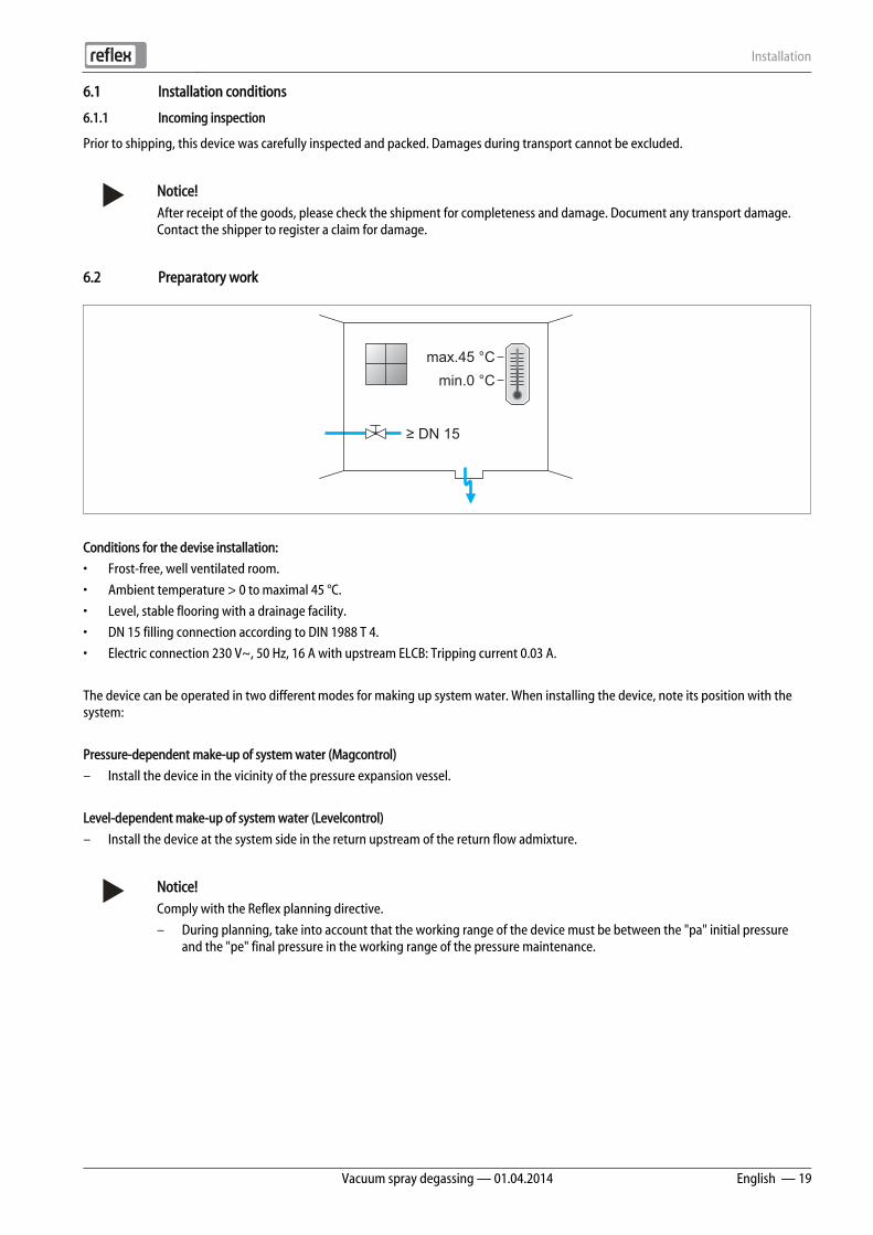
Conditions for the devise installation:
• Frost-free, well ventilated room.
• Ambient temperature > 0 to maximal 45 °C.
• Level, stable flooring with a drainage facility.
• DN 15 filling connection according to DIN 1988 T 4.
• Electric connection 230 V~, 50 Hz, 16 A with upstream ELCB: Tripping current 0.03 A.
The device can be operated in two different modes for making up system water. When installing the device, note its position with the system:
Pressure-dependent make-up of system water (Magcontrol)
– Install the device in the vicinity of the pressure expansion vessel.
Level-dependent make-up of system water (Levelcontrol)
– Install the device at the system side in the return upstream of the return flow admixture.
Notice! Comply with the Reflex planning directive.
– During planning, take into account that the working range of the device must be between the "pa" initial pressure and the "pe" final pressure in the working range of the pressure maintenance.
max.45 °Cmin.0 °C
≥ DN 15
Installation
20 — English Vacuum spray degassing — 01.04.2014
6.3 Execution
Attention! – Damage caused by improper installation • Remember that the connection of pipelines or equipment originating with the system may cause additional stresses
to the device.
– Ensure a stress-free installation of the pipe connections between the device and the overall system.
In heating systems, install the device in the return side.
– In this manner, you ensure that the device is operated within the permissible pressure and temperature ranges.
– In systems with return admixtures or hydraulic switching points, the device must be installed upstream of the admixture point to ensure degassing in the "V" main flow volume at temperatures ≤ 70 °C.
The device is pre-wired and must be adapted for the local system conditions. Complete the water-side connection to the system and the electric connection as shown in the terminal diagram, see chapter 6.5.1 "Terminal diagram" on page 28 .
Notice! For installation, note the operability of the valves and the inlet options of the connecting lines.
6.3.1 Fitting the add-on components
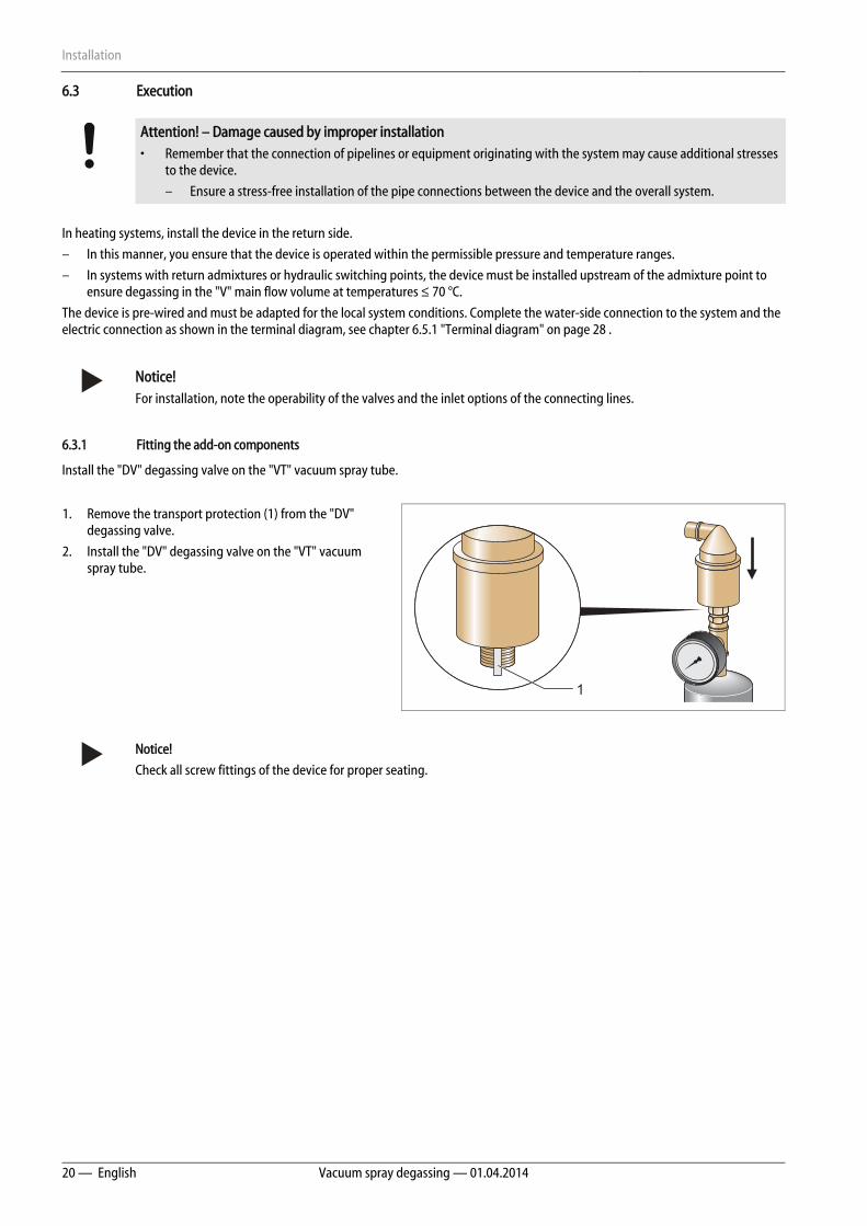
Install the "DV" degassing valve on the "VT" vacuum spray tube.
1. Remove the transport protection (1) from the "DV" degassing valve.
2. Install the "DV" degassing valve on the "VT" vacuum spray tube.
Notice!
Check all screw fittings of the device for proper seating.
1
Installation
Vacuum spray degassing — 01.04.2014 English — 21
6.3.2 Floor/wall installation
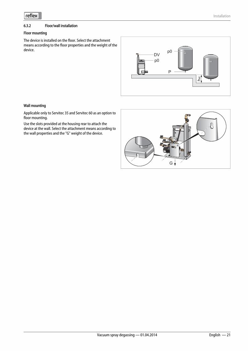
Floor mounting
The device is installed on the floor. Select the attachment means according to the floor properties and the weight of the device.
Wall mounting
Applicable only to Servitec 35 and Servitec 60 as an option to floor mounting.
Use the slots provided at the housing rear to attach the device at the wall. Select the attachment means according to the wall properties and the "G" weight of the device.
hst
p0
p0DV
P
G
Installation
22 — English Vacuum spray degassing — 01.04.2014
6.3.3 Hydraulic connection
6.3.3.1 Degassing line to the system
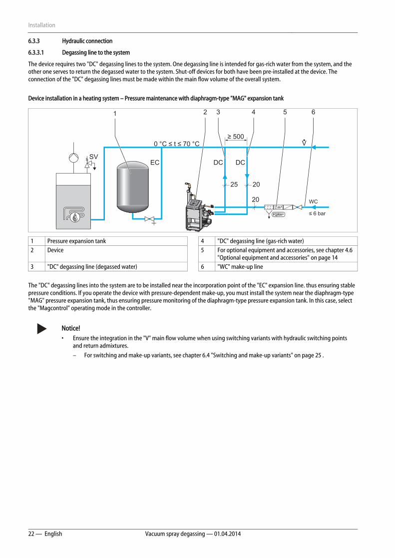
The device requires two "DC" degassing lines to the system. One degassing line is intended for gas-rich water from the system, and the other one serves to return the degassed water to the system. Shut-off devices for both have been pre-installed at the device. The connection of the "DC" degassing lines must be made within the main flow volume of the overall system.
Device installation in a heating system – Pressure maintenance with diaphragm-type "MAG" expansion tank
1 Pressure expansion tank 4 "DC" degassing line (gas-rich water) 2 Device 5 For optional equipment and accessories, see chapter 4.6
"Optional equipment and accessories" on page 14 3 "DC" degassing line (degassed water) 6 "WC" make-up line
The "DC" degassing lines into the system are to be installed near the incorporation point of the "EC" expansion line. thus ensuring stable pressure conditions. If you operate the device with pressure-dependent make-up, you must install the system near the diaphragm-type "MAG" pressure expansion tank, thus ensuring pressure monitoring of the diaphragm-type pressure expansion tank. In this case, select the "Magcontrol" operating mode in the controller.
Notice! • Ensure the integration in the "V" main flow volume when using switching variants with hydraulic switching points
and return admixtures.
– For switching and make-up variants, see chapter 6.4 "Switching and make-up variants" on page 25 .
WC
≤ 6 bar
SV
V
20
DCEC DC
20
25
0 °C ≤ t ≤ 70 °C≥ 500
1 2 3 4 5 6
Installation
Vacuum spray degassing — 01.04.2014 English — 23
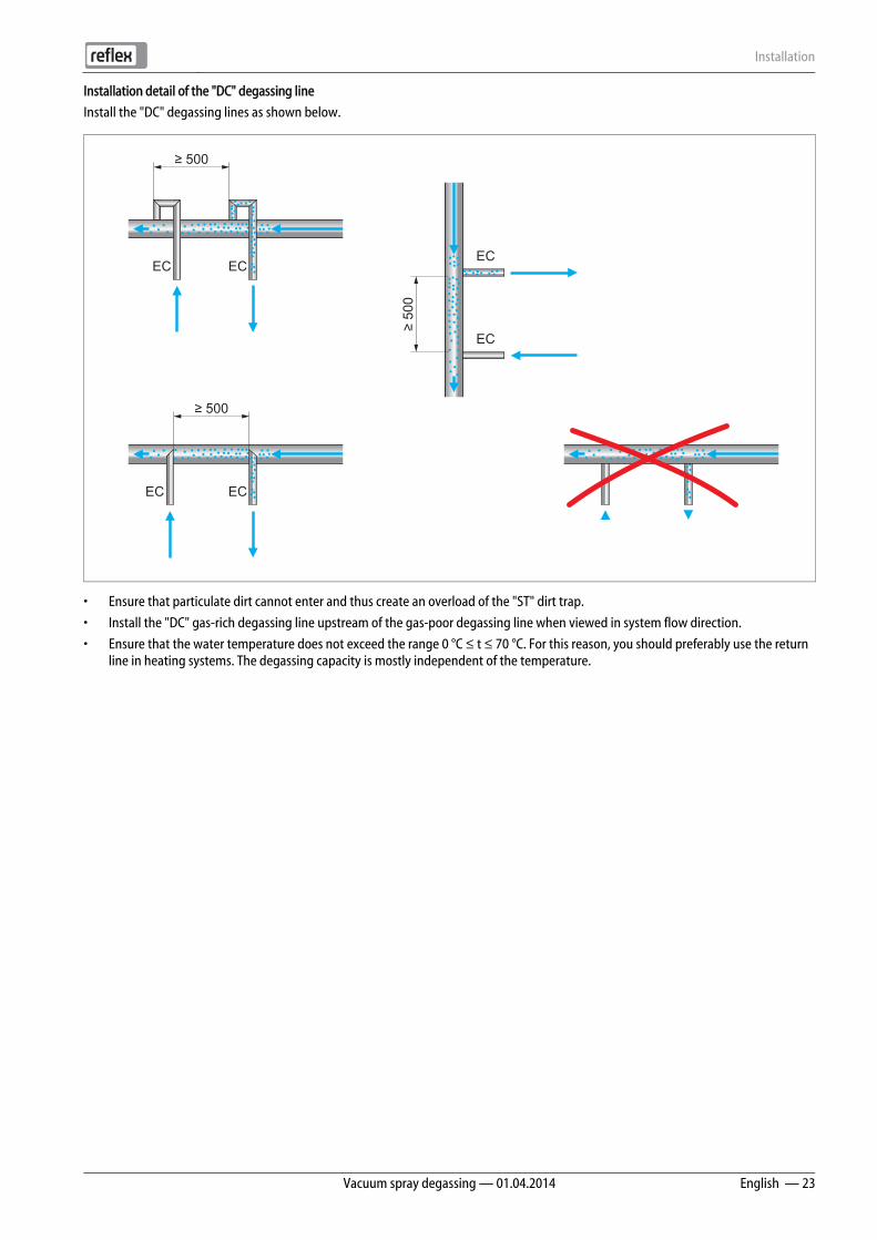
Installation detail of the "DC" degassing line
Install the "DC" degassing lines as shown below.
• Ensure that particulate dirt cannot enter and thus create an overload of the "ST" dirt trap.
• Install the "DC" gas-rich degassing line upstream of the gas-poor degassing line when viewed in system flow direction.
• Ensure that the water temperature does not exceed the range 0 °C ≤ t ≤ 70 °C. For this reason, you should preferably use the return line in heating systems. The degassing capacity is mostly independent of the temperature.
ECEC
≥ 500
ECEC
≥ 500
EC
EC
≥ 50
0
Installation
24 — English Vacuum spray degassing — 01.04.2014
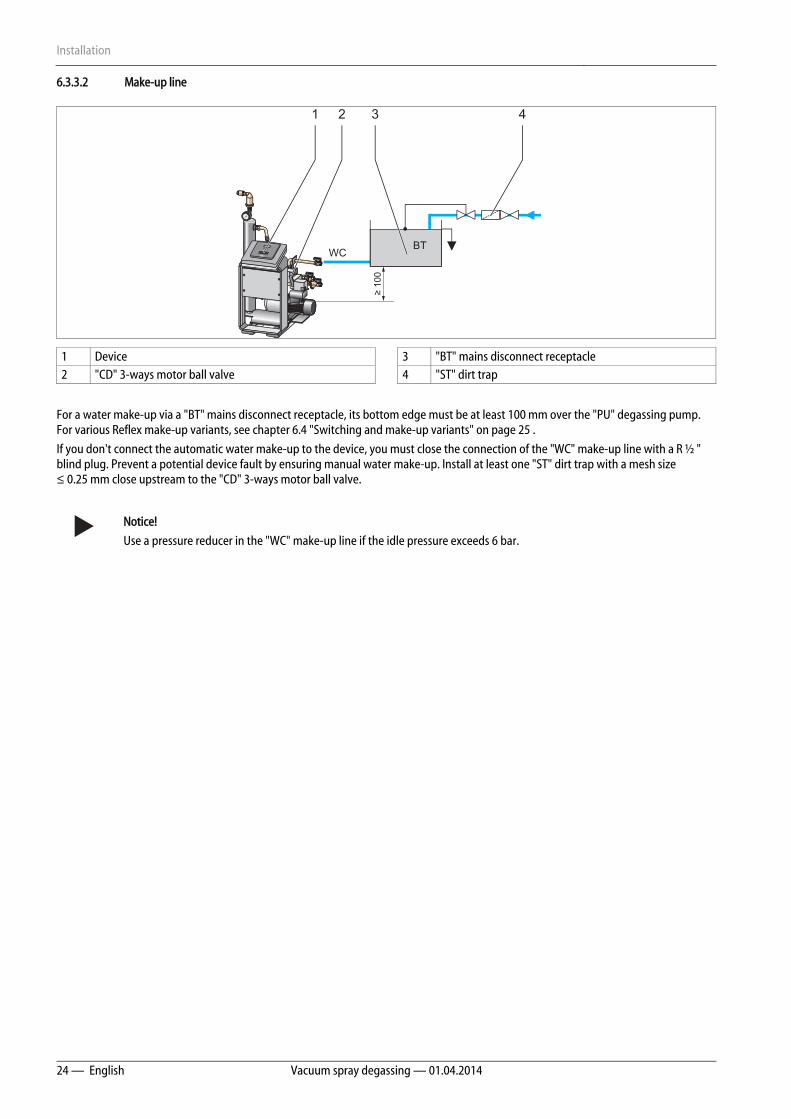
6.3.3.2 Make-up line
1 Device 3 "BT" mains disconnect receptacle 2 "CD" 3-ways motor ball valve 4 "ST" dirt trap
For a water make-up via a "BT" mains disconnect receptacle, its bottom edge must be at least 100 mm over the "PU" degassing pump. For various Reflex make-up variants, see chapter 6.4 "Switching and make-up variants" on page 25 .
If you don't connect the automatic water make-up to the device, you must close the connection of the "WC" make-up line with a R ½ " blind plug. Prevent a potential device fault by ensuring manual water make-up. Install at least one "ST" dirt trap with a mesh size ≤ 0.25 mm close upstream to the "CD" 3-ways motor ball valve.
Notice!
Use a pressure reducer in the "WC" make-up line if the idle pressure exceeds 6 bar.
≥ 10
0
WCBT
1 2 3 4
Installation
Vacuum spray degassing — 01.04.2014 English — 25
6.4 Switching and make-up variants
Use the Customer menu of the device controller to set the make-up mode, see chapter 8.2.1 "Customer menu" on page 44 .
• Pressure-dependent "Magcontrol" make-up mode.
• Level-dependent make-up with "Levelcontrol".
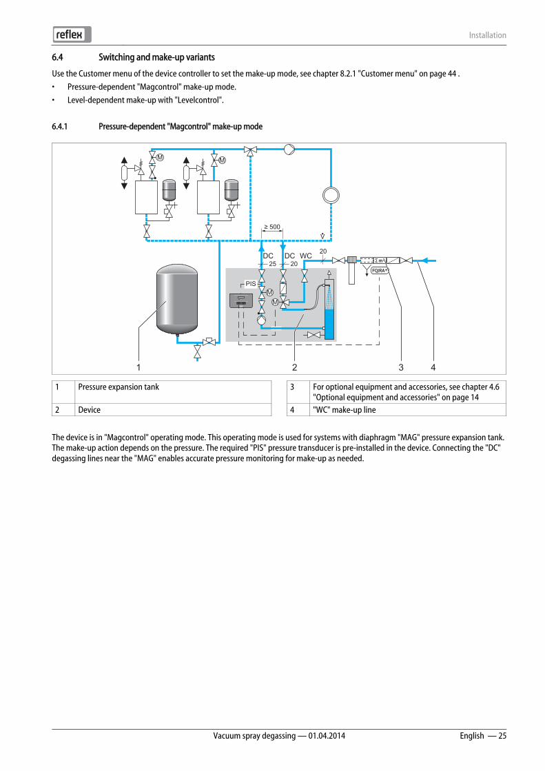
6.4.1 Pressure-dependent "Magcontrol" make-up mode
1 Pressure expansion tank 3 For optional equipment and accessories, see chapter 4.6 "Optional equipment and accessories" on page 14
2 Device 4 "WC" make-up line
The device is in "Magcontrol" operating mode. This operating mode is used for systems with diaphragm "MAG" pressure expansion tank. The make-up action depends on the pressure. The required "PIS" pressure transducer is pre-installed in the device. Connecting the "DC" degassing lines near the "MAG" enables accurate pressure monitoring for make-up as needed.
M
MM
M
V
WCDCDC
PIS
25 20
20
≥ 500
1 2 3 4

Installation
26 — English Vacuum spray degassing — 01.04.2014
6.4.2 Level dependent "Levelcontrol" make-up mode
The device is in "Levelcontrol" operating mode which is used for systems with pressure maintenance stations.
This operating mode enables an elastic operation at constant pressure.
1 Pressure maintaining station 3 For optional equipment and accessories, see chapter 4.6 "Optional equipment and accessories" on page 14
2 Device 4 "WC" make-up line
Make-up is executed depending on the water level measured with the "LIS" level sensor in the expansion tank of the pressure maintaining station. For a make-up request, the controller activates a 230 V signal to the device controller.
PIS
LIS
M
MM
M
V
WCDCDC230VSignal 25 20
20
≥ 500
1 2 3 4
Installation
Vacuum spray degassing — 01.04.2014 English — 27
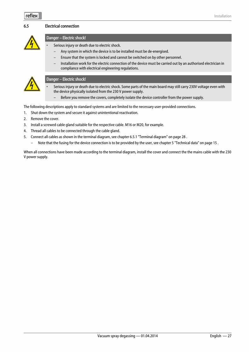
6.5 Electrical connection
Danger – Electric shock!
• Serious injury or death due to electric shock.
– Any system in which the device is to be installed must be de-energised.
– Ensure that the system is locked and cannot be switched on by other personnel.
– Installation work for the electric connection of the device must be carried out by an authorised electrician in compliance with electrical engineering regulations.
Danger – Electric shock!
• Serious injury or death due to electric shock. Some parts of the main board may still carry 230V voltage even with the device physically isolated from the 230 V power supply.
– Before you remove the covers, completely isolate the device controller from the power supply.
The following descriptions apply to standard systems and are limited to the necessary user-provided connections.
1. Shut down the system and secure it against unintentional reactivation.
2. Remove the cover.
3. Install a screwed cable gland suitable for the respective cable. M16 or M20, for example.
4. Thread all cables to be connected through the cable gland.
5. Connect all cables as shown in the terminal diagram, see chapter 6.5.1 "Terminal diagram" on page 28 .
– Note that the fusing for the device connection is to be provided by the user, see chapter 5 "Technical data" on page 15 .
When all connections have been made according to the terminal diagram, install the cover and connect the the mains cable with the 230 V power supply.

Installation
28 — English Vacuum spray degassing — 01.04.2014
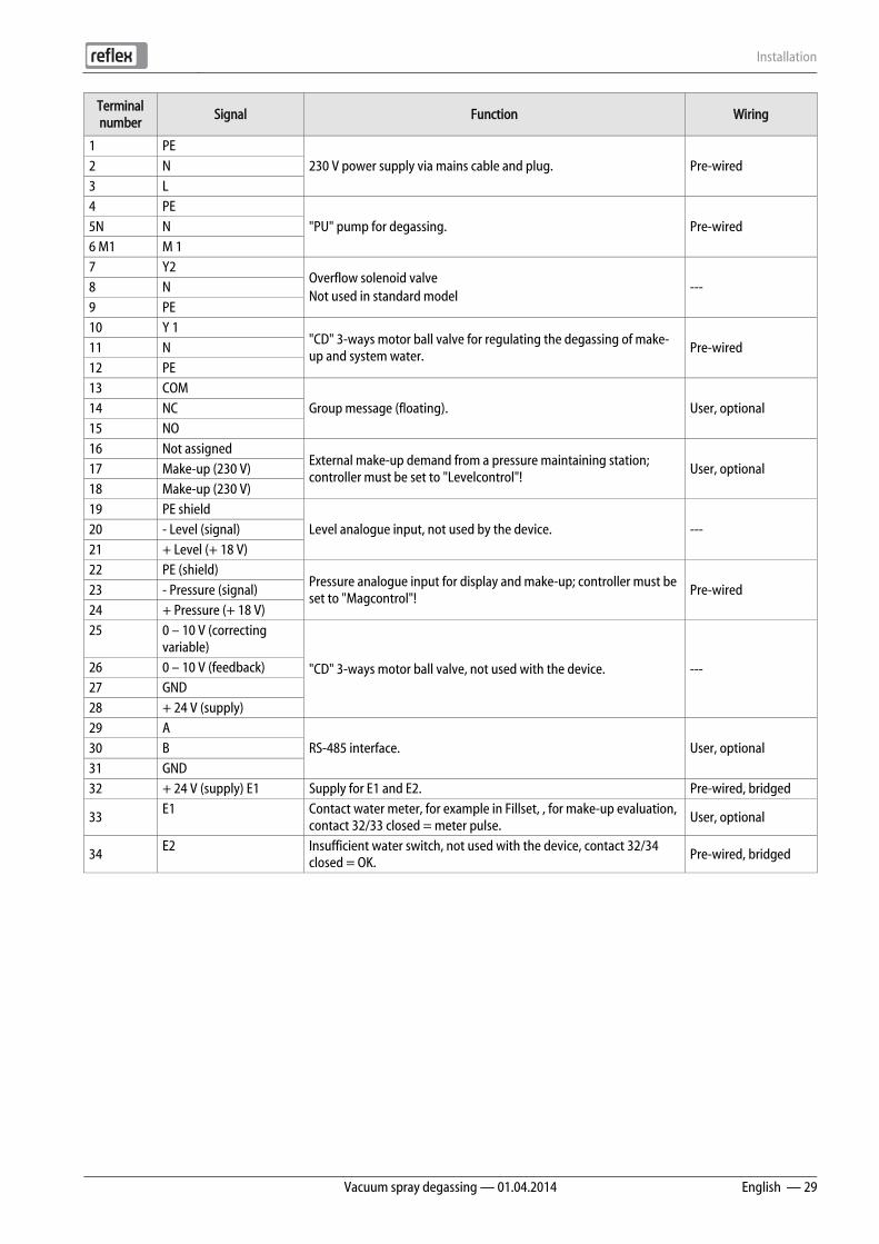
6.5.1 Terminal diagram
1 "L" fuse for electronics and solenoid valves 9 Digital inputs • Water meter • Insufficient water
2 "N" fuse for solenoid valves 10 "CD" 3-ways motor ball valve 3 Overflow valve (not for motor ball valve) 11 Pressure analogue input 4 Group message 12 External make-up demand (Levelcontrol only) 5 Optional for second pressure value 13 Make-up valve 6 "CD" 3-ways motor ball valve 14 Pump 7 RS-485 interface 15 Mains supply 8 Shielding
7 8 9Y2 N PE
13 14 15COM NC NO
19 20 21 25 26 29 30 31A(+) B(+)
GNDRS-485
RS-485
32 33 34+24V WZ WM
22 23 24 27 28+24VGND
16 17 1810 11 12Y1 N PE
T 0,315 A T 0,315 A
1 2 3PE N L
4 5 6PE N M1
Error Auto
Quit
Menu Auto Manual Stop
Ok
1
15
43 5 6 7
14 13 12 11 10 9 8
2
Installation
Vacuum spray degassing — 01.04.2014 English — 29
Terminal number
Signal Function Wiring
1 PE 230 V power supply via mains cable and plug. Pre-wired 2 N
3 L 4 PE
"PU" pump for degassing. Pre-wired 5N N 6 M1 M 1 7 Y2
Overflow solenoid valve Not used in standard model
--- 8 N 9 PE 10 Y 1
"CD" 3-ways motor ball valve for regulating the degassing of make-up and system water.
Pre-wired 11 N 12 PE 13 COM
Group message (floating). User, optional 14 NC 15 NO 16 Not assigned
External make-up demand from a pressure maintaining station; controller must be set to "Levelcontrol"!
User, optional 17 Make-up (230 V) 18 Make-up (230 V) 19 PE shield
Level analogue input, not used by the device. --- 20 - Level (signal) 21 + Level (+ 18 V) 22 PE (shield)
Pressure analogue input for display and make-up; controller must be set to "Magcontrol"!
Pre-wired 23 - Pressure (signal) 24 + Pressure (+ 18 V) 25 0 – 10 V (correcting
variable)
"CD" 3-ways motor ball valve, not used with the device. --- 26 0 – 10 V (feedback) 27 GND 28 + 24 V (supply) 29 A
RS-485 interface. User, optional 30 B 31 GND 32 + 24 V (supply) E1 Supply for E1 and E2. Pre-wired, bridged
33 E1 Contact water meter, for example in Fillset, , for make-up evaluation,
contact 32/33 closed = meter pulse. User, optional
34 E2 Insufficient water switch, not used with the device, contact 32/34
closed = OK. Pre-wired, bridged

Installation
30 — English Vacuum spray degassing — 01.04.2014
6.5.2 RS-485 interface
6.5.2.1 Connecting the RS-485 interface
• Use a shielded cable to connect the interface to terminals 29, 30, 31 of the main board in the control cabinet.
– For connecting the interface, see chapter 6.5 "Electrical connection" on page 27 .
• When using the device with a control centre not supporting an RS-485 interface (RS-232, for example), you must use a corresponding adapter.
Notice! • For connecting the interface use only a cable with these properties.
– LJYCY (TP), 4 × 2 × 0.8, maximum overall bus length 1000 m.
Installation
Vacuum spray degassing — 01.04.2014 English — 31
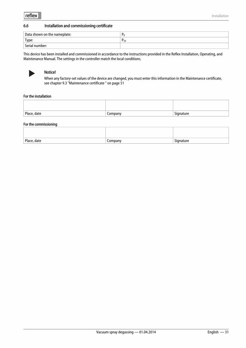
6.6 Installation and commissioning certificate
Data shown on the nameplate: P0
Type: PSV
Serial number:
This device has been installed and commissioned in accordance to the instructions provided in the Reflex Installation, Operating, and Maintenance Manual. The settings in the controller match the local conditions.
Notice! When any factory-set values of the device are changed, you must enter this information in the Maintenance certificate, see chapter 9.3 "Maintenance certificate " on page 51
For the installation
Place, date Company Signature For the commissioning
Place, date Company Signature

Commissioning
32 — English Vacuum spray degassing — 01.04.2014
7 Commissioning
Notice! • The proper installation and commissioning must be confirmed in the installation, commissioning and maintenance
certificate. This certificate is prerequisite for any warranty claim.
– Have the Reflex Customer Service carry out commissioning and the annual maintenance.
7.1 Checking the requirements for commissioning
The device is ready for commissioning when the tasks described in Chapter Installation have been concluded.
• The device has been mounted.
• The water-side connection of the device to the system has been created and the system pressure maintenance is operational.
• The water-side connection of the device to the make-up has been created and is operational, if automatic make-up is required.
• The connection pipes of the device have been purged and cleaned of welding residue and dirt before commissioning.
• The entire system is filled with water and all gases have been vented in order to ensure a circulation through the entire system.
• The electrical connection has been created according to applicable national and local regulations.
7.2 Setting the minimum operating pressure for Magcontrol
The "P0" minimum operating pressure is required only for the make-up with pressure-dependent control in systems with the MAG pressure expansion tank. Activate "Magcontrol" in the controller's Customer menu.
– Determine the "P0" minimum operating pressure of the device relative to the "p0" initial pressure of the MAG pressure expansion tank.
– The device is installed at the same height as the MAG pressure expansion tank, hst = 0, P0 = p0*
– The device is installed at a lower height than the MAG pressure expansion tank, P0 = p0 + hst/10*
– The device is installed at a higher height than the MAG pressure expansion tank, P0 = p0 - hst/10*
* p0 in bar, hst in m
Notice! • Comply with the Reflex planning directive.
– During planning, take into account that the working range of the device in the working range of the pressure maintenance must be between the "pa" initial pressure and the "pe" final pressure.
hst
p0
p0
Commissioning
Vacuum spray degassing — 01.04.2014 English — 33
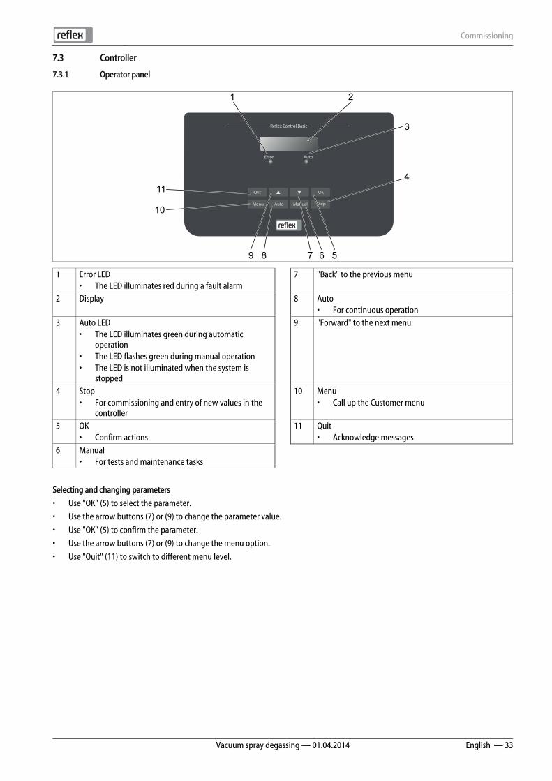
7.3 Controller
7.3.1 Operator panel
1 Error LED • The LED illuminates red during a fault alarm
7 "Back" to the previous menu
2 Display 8 Auto • For continuous operation
3 Auto LED • The LED illuminates green during automatic
operation • The LED flashes green during manual operation • The LED is not illuminated when the system is
stopped
9 "Forward" to the next menu
4 Stop • For commissioning and entry of new values in the
controller
10 Menu • Call up the Customer menu
5 OK • Confirm actions
11 Quit • Acknowledge messages
6 Manual • For tests and maintenance tasks
Selecting and changing parameters
• Use "OK" (5) to select the parameter.
• Use the arrow buttons (7) or (9) to change the parameter value.
• Use "OK" (5) to confirm the parameter.
• Use the arrow buttons (7) or (9) to change the menu option.
• Use "Quit" (11) to switch to different menu level.
Error Auto
Quit
Menu Auto Manual Stop
Ok11
10
9 8 7 6 5
4
1
3
2
Commissioning
34 — English Vacuum spray degassing — 01.04.2014
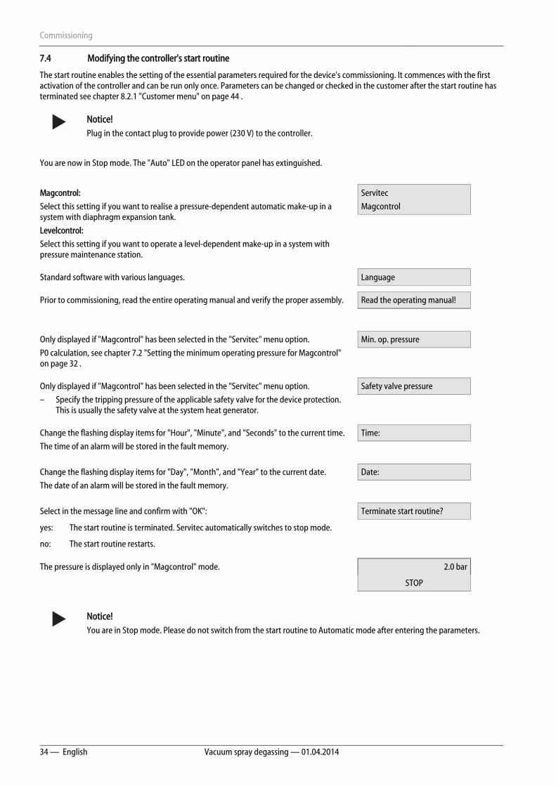
7.4 Modifying the controller's start routine
The start routine enables the setting of the essential parameters required for the device's commissioning. It commences with the first activation of the controller and can be run only once. Parameters can be changed or checked in the customer after the start routine has terminated see chapter 8.2.1 "Customer menu" on page 44 .
Notice! Plug in the contact plug to provide power (230 V) to the controller.
You are now in Stop mode. The "Auto" LED on the operator panel has extinguished.
Magcontrol:
Select this setting if you want to realise a pressure-dependent automatic make-up in a system with diaphragm expansion tank.
Levelcontrol:
Select this setting if you want to operate a level-dependent make-up in a system with pressure maintenance station.
Servitec
Magcontrol
Standard software with various languages. Language
Prior to commissioning, read the entire operating manual and verify the proper assembly. Read the operating manual!
Only displayed if "Magcontrol" has been selected in the "Servitec" menu option.
P0 calculation, see chapter 7.2 "Setting the minimum operating pressure for Magcontrol" on page 32 .
Min. op. pressure
Only displayed if "Magcontrol" has been selected in the "Servitec" menu option.
– Specify the tripping pressure of the applicable safety valve for the device protection. This is usually the safety valve at the system heat generator.
Safety valve pressure
Change the flashing display items for "Hour", "Minute", and "Seconds" to the current time.
The time of an alarm will be stored in the fault memory.
Time:
Change the flashing display items for "Day", "Month", and "Year" to the current date.
The date of an alarm will be stored in the fault memory.
Date:
Select in the message line and confirm with "OK": Terminate start routine?
yes: The start routine is terminated. Servitec automatically switches to stop mode.
no: The start routine restarts.
The pressure is displayed only in "Magcontrol" mode. 2.0 bar
STOP
Notice! You are in Stop mode. Please do not switch from the start routine to Automatic mode after entering the parameters.
Commissioning
Vacuum spray degassing — 01.04.2014 English — 35
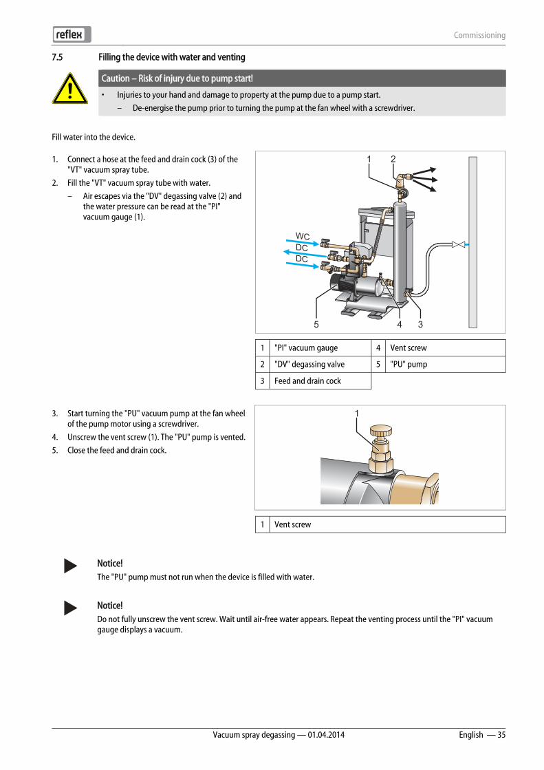
7.5 Filling the device with water and venting
Caution – Risk of injury due to pump start!
• Injuries to your hand and damage to property at the pump due to a pump start.
– De-energise the pump prior to turning the pump at the fan wheel with a screwdriver.
Fill water into the device.
1. Connect a hose at the feed and drain cock (3) of the "VT" vacuum spray tube.
2. Fill the "VT" vacuum spray tube with water.
– Air escapes via the "DV" degassing valve (2) and the water pressure can be read at the "PI" vacuum gauge (1).
1 "PI" vacuum gauge 4 Vent screw
2 "DV" degassing valve 5 "PU" pump
3 Feed and drain cock
3. Start turning the "PU" vacuum pump at the fan wheel of the pump motor using a screwdriver.
4. Unscrew the vent screw (1). The "PU" pump is vented.
5. Close the feed and drain cock.
1 Vent screw
Notice! The "PU" pump must not run when the device is filled with water.
Notice! Do not fully unscrew the vent screw. Wait until air-free water appears. Repeat the venting process until the "PI" vacuum gauge displays a vacuum.
WC
DCDC
1 2
345
1

Commissioning
36 — English Vacuum spray degassing — 01.04.2014
7.6 Vacuum test
Carefully perform the vacuum test to ensure the proper functioning of the device.
1 Close the ball valve (2) with dirt trap (3). The second ball valve (1) remains open.
2 Generate a vacuum with the manual mode of the controller.
• Press "Manual" on the controller's operator panel.
• Use the "Back" toggle button to select "SE" system degassing at the operator panel.
– The pump will start after a time delay of 50 seconds.
3 Use the "Back" toggle button to switch off "SE" system degassing after the pump runs for 10 seconds.
• Record the vacuum value displayed at the vacuum gauge.
4 Observe the "PI" vacuum gauge (1) for approximately 10 minutes. The pressure must not change. If the pressure has increased, check the device for leaks.
• Check all screw fittings at the "VT" vacuum spray tube for leaks.
• Check the vent screw at the "PU" pump for leaks.
• Check the "DV" degassing valve at the "VT" vacuum spray tube for leaks.
5 After the vacuum test has been concluded successfully, open the ball valve with dirt trap.
6 If the controller displays the "Insufficient water" error message, confirm with "Quit".
The vacuum test is completed.
Notice! • The obtainable vacuum corresponds to the saturation pressure at the existing water temperature.
– At 10 °C, a vacuum of approximately. -1 bar can be obtained.
Notice! • Repeat steps 2 to 4 until no further pressure rise is observed.
1
2
3
1
Commissioning
Vacuum spray degassing — 01.04.2014 English — 37
7.7 Filling system with device
In systems with a water volume less than 3000 litres and a pressure maintenance with diaphragm-type pressure expansion tanks, the device may be used to fill with degassed water. Thus, the oxygen content and the content of free gases is reduced for commissioning.
Set the controller to the following operating modes:
• "Magcontrol" automatic make-up, see chapter 8.2.1 "Customer menu" on page 44 .
• Manual operation, see chapter 8.1.2 "Manual mode" on page 43 .
– "NE" make-up degassing mode.
The controller calculates the required filling pressure. As soon as this value has been attained, the controller automatically stops the filling process. If the maximum filling time (10 hours by default) is exceeded, the system aborts the make-up process with an error message. After the cause has been found, acknowledge the error message by pressing "Quit" at the controller's operating panel and continue with the filling process, see chapter 8.2.4 "Messages" on page 46 . After filling is completed, you must vent the system to ensure proper circulation through the entire system.
Notice! • Monitor the system for the entire automatic filling process..
Notice! • Filling the system with water is not part of the deliverables of the Reflex Customer Service.
Commissioning
38 — English Vacuum spray degassing — 01.04.2014
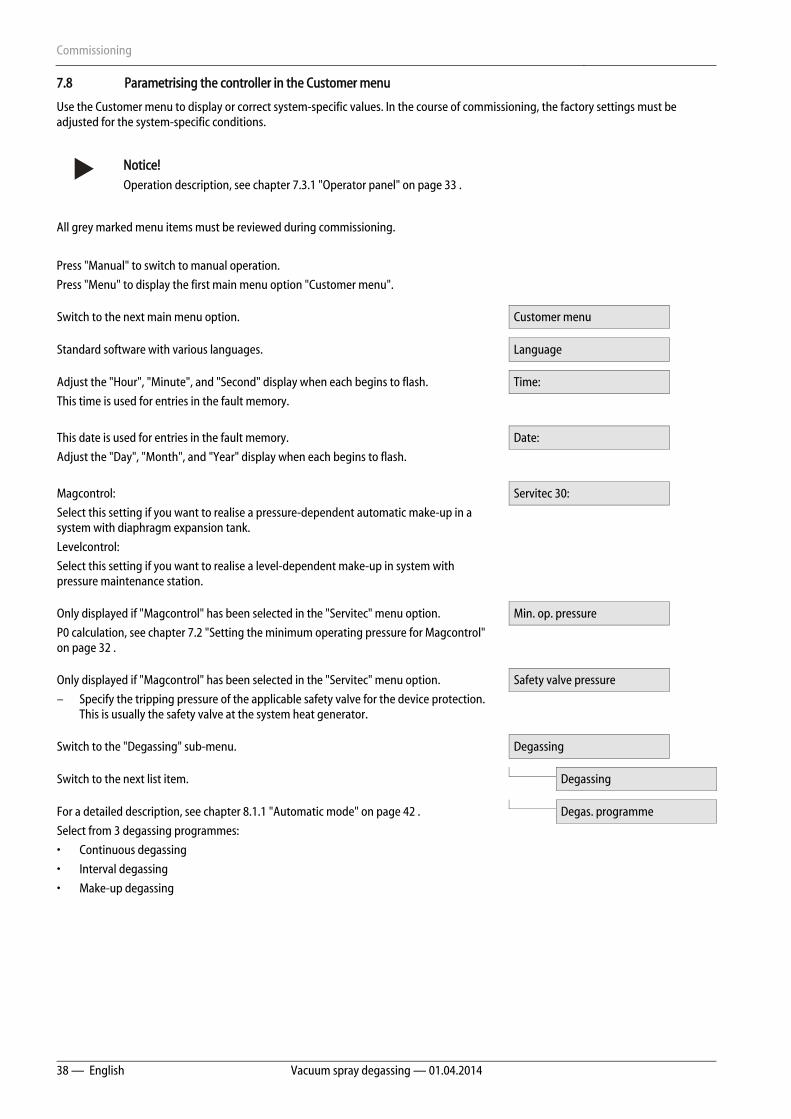
7.8 Parametrising the controller in the Customer menu
Use the Customer menu to display or correct system-specific values. In the course of commissioning, the factory settings must be adjusted for the system-specific conditions.
Notice! Operation description, see chapter 7.3.1 "Operator panel" on page 33 .
All grey marked menu items must be reviewed during commissioning.
Press "Manual" to switch to manual operation.
Press "Menu" to display the first main menu option "Customer menu".
Switch to the next main menu option. Customer menu
Standard software with various languages. Language
Adjust the "Hour", "Minute", and "Second" display when each begins to flash.
This time is used for entries in the fault memory.
Time:
This date is used for entries in the fault memory.
Adjust the "Day", "Month", and "Year" display when each begins to flash.
Date:
Magcontrol:
Select this setting if you want to realise a pressure-dependent automatic make-up in a system with diaphragm expansion tank.
Levelcontrol:
Select this setting if you want to realise a level-dependent make-up in system with pressure maintenance station.
Servitec 30:
Only displayed if "Magcontrol" has been selected in the "Servitec" menu option.
P0 calculation, see chapter 7.2 "Setting the minimum operating pressure for Magcontrol" on page 32 .
Min. op. pressure
Only displayed if "Magcontrol" has been selected in the "Servitec" menu option.
– Specify the tripping pressure of the applicable safety valve for the device protection. This is usually the safety valve at the system heat generator.
Safety valve pressure
Switch to the "Degassing" sub-menu. Degassing
Switch to the next list item.
Degassing
For a detailed description, see chapter 8.1.1 "Automatic mode" on page 42 .
Select from 3 degassing programmes:
• Continuous degassing
• Interval degassing
• Make-up degassing
Degas. programme
Commissioning
Vacuum spray degassing — 01.04.2014 English — 39
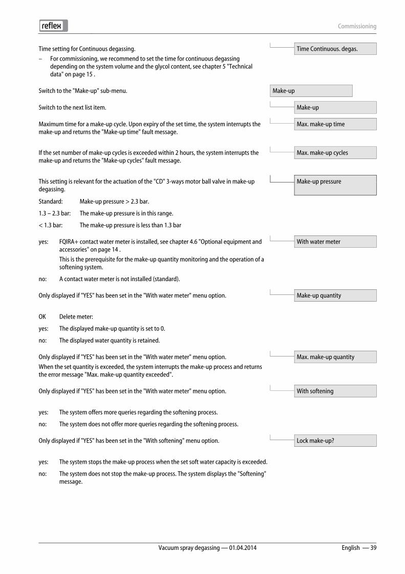
Time setting for Continuous degassing.
– For commissioning, we recommend to set the time for continuous degassing depending on the system volume and the glycol content, see chapter 5 "Technical data" on page 15 .
Time Continuous. degas.
Switch to the "Make-up" sub-menu. Make-up
Switch to the next list item.
Make-up
Maximum time for a make-up cycle. Upon expiry of the set time, the system interrupts the make-up and returns the "Make-up time" fault message.
Max. make-up time
If the set number of make-up cycles is exceeded within 2 hours, the system interrupts the make-up and returns the "Make-up cycles" fault message.
Max. make-up cycles
This setting is relevant for the actuation of the "CD" 3-ways motor ball valve in make-up degassing.
Make-up pressure
Standard: Make-up pressure > 2.3 bar.
1.3 – 2.3 bar: The make-up pressure is in this range.
< 1.3 bar: The make-up pressure is less than 1.3 bar
yes: FQIRA+ contact water meter is installed, see chapter 4.6 "Optional equipment and accessories" on page 14 .
This is the prerequisite for the make-up quantity monitoring and the operation of a softening system.
With water meter
no: A contact water meter is not installed (standard).
Only displayed if "YES" has been set in the "With water meter" menu option.
Make-up quantity
OK Delete meter:
yes: The displayed make-up quantity is set to 0.
no: The displayed water quantity is retained.
Only displayed if "YES" has been set in the "With water meter" menu option.
When the set quantity is exceeded, the system interrupts the make-up process and returns the error message "Max. make-up quantity exceeded".
Max. make-up quantity
Only displayed if "YES" has been set in the "With water meter" menu option.
With softening
yes: The system offers more queries regarding the softening process.
no: The system does not offer more queries regarding the softening process.
Only displayed if "YES" has been set in the "With softening" menu option.
Lock make-up?
yes: The system stops the make-up process when the set soft water capacity is exceeded.
no: The system does not stop the make-up process. The system displays the "Softening" message.

Commissioning
40 — English Vacuum spray degassing — 01.04.2014
Only displayed if "YES" has been set in the "With softening" menu option.
Is calculated from the difference of the overall water hardness GHactual and the target water hardness GHtarget as defined by the manufacturer specification:
Hardness reduction = GHactual-GHtargetl °dH
Enter the value in the controller. Consult the manufacturer information for third-party products.
Hardness reduction
Only displayed if "YES" has been set in the "With softening" menu option.
The attainable soft water capacity is calculated from the type of softening used and the specified hardness reduction.
• Fillsoft I : Soft water capacity ≤ 6000/hardness red. l
• Fillsoft II : Soft water capacity ≤ 12000/hardness red. l
Enter the value in the controller. Consult the manufacturer information for third-party products.
Cap. soft water
Only displayed if "YES" has been set in the "With softening" menu option.
Available soft water capacity.
Remaining cap. soft w.
Only displayed if "YES" has been set in the "With softening" menu option.
Manufacturer specification for the replacement interval of the softening cartridges, regardless of the calculated soft water capacity. The system displays the "Softening" message.
Replacement in
Recommended maintenance message. Next maintenance
Off: Without maintenance recommendation.
001 – 060: Maintenance recommendation in months.
For the output of messages to the floating contact, see chapter 8.2.4 "Messages" on page 46 .
Floating fault contact
yes: Output of all messages.
no: Output of all messages identified with "xxx" ("01", for example).
Switch to the fault memory or into the next main menu option. Fault memory
The last 20 alarms are stored with fault type, date, time, and fault code.
See the chapter "Messages" for more information about the ER... messages.
ER 01…xx
Switch to the parameter memory or into the next main menu option. Parameter memory
The last 10 entries of the minimum working pressure are stored with date and time.
P0 = xx.x bar
Position of the "CD" motor ball valve at the pressure side of the pump to
the controller of the degassing process.
Pos. motor ball valve
Information about the software version. Servitec 35-95

Commissioning
Vacuum spray degassing — 01.04.2014 English — 41
7.9 Starting Automatic mode
The automatic mode can be started as soon as the system is filled with water and the gases contained have been vented.
– At the controller, press "Auto" for automatic operation.
– During commissioning, continuous degassing is automatically activated to remove any residual free or dissolved gases from the system. This time can be set in the Customer menu as required by the system conditions. The default setting is 24 hours. Subsequent to the continuous degassing, the device automatically switches to interval degassing.
Notice! The commissioning process is now concluded.
Notice! The "ST" dirt trap in the "DC" degassing line must be cleaned after the expiry of the continuous degassing time at the latest, see chapter 9.1.1 "Cleaning the dirt trap" on page 50 .

Operation
42 — English Vacuum spray degassing — 01.04.2014
8 Operation 8.1 Operating modes
8.1.1 Automatic mode
Upon successful commissioning, you can activate the automatic mode with the degassing functions and, optionally, the automatic make-up. The device controller monitors the functions. Faults are displayed and evaluated.
For automatic mode, you can set three different degassing programmes in the Customer menu, see chapter 8.2.1 "Customer menu" on page 44 . Relevant information is displayed in the message line of the controller display.
Continuous degassing of the system water
Select this programme after commissioning and repairs of the connected system. The device will continuously degas for a set period of time. Free and dissolved gases are quickly removed. Upon request of make-up, make-up degassing is automatically activated for the set make-up time. In "Magcontrol" mode, the pressure is monitored and displayed.
Start/setting:
– Automatic start after execution of the start routine during commissioning. – Activated from the Customer menu. – Degassing time. Can be set in the Customer menu, dependent on the actual system.
The default setting is 24 hours. After expiry of the set time, the device automatically switches to interval degassing.
Continuous degassing
Interval degassing of the system water
Designed for continuous operation. An interval comprises a number of degassing cycles, with the number to be set in the Service menu. An idling time follows an interval. The daily start of the interval degassing can be set to a specific time. Start/setting: – Automatic activation upon expiry of continuous degassing. – Degassing cycles: 8 cycles per interval, to be set in the Service menu. – Start time interval: To be set in the Service menu. – Idling time between intervals: To be set in the Service menu.
Servitec Interval degassing
Degassing the make-up water
Is automatically activated for every make-up during continuous or interval degassing. The corresponding setting must have been made in the Customer menu.
The 3-ways motor ball valve switches the volume flow from system to make-up water. The process is the same as in continuous degassing. If the system water is not to be degassed or if the system is in Summer operation with circulating pumps shut down, you can activate the make-up degassing in the Customer menu.
Activation/setting:
– Automatic activation for every make-up.
– Activated from the Customer menu.
– Degassing time = Make-up time.
Servitec
Make-up degassing

Operation
Vacuum spray degassing — 01.04.2014 English — 43
8.1.2 Manual mode
The manual mode is intended for test and service tasks.
Press "Manual" at the controller. The Auto LED at the operator panel flashes to visually indicate that manual mode is active. Manually activate or deactivate the "SE" system degassing or the "NE" make-up degassing.
"SE" system degassing of the system water
The system degassing process corresponds to the continuous degassing in Automatic mode. The degassing time, however,
is not automatically limited. This setting is required for the vacuum test during commissioning see chapter 7.6 "Vacuum test" on page 36 and test runs during service calls see chapter 9.2 "Inspecting system degassing and make-up degassing" on page 50 .
"NE" make-up degassing of the fill and make-up water
The make-up degassing is required for test runs during service calls see chapter 9.2 "Inspecting system degassing and make-up degassing" on page 50 and in the "Magcontrol" mode when filling the entire system with water.
• "Next" and "Back" buttons
– Selecting "NE" or "SE".
• "Auto" button
– Return to Automatic mode.
2.5 bar NE▼* SE▲* 010 h
* Flashing mode "NE▼“ or "SE▲“ is activated
8.1.3 Stop mode
The Stop mode is intended for the device commissioning.
Press "Stop" on the controller. The Auto LED at the operator panel extinguishes.
Except for the display of information, the device is non-functional in Stop mode. Function monitoring is stopped.
The "PU" pump is switched off. The system returns an alarm if the Stop mode is activated for more than 4 hours.
If "Floating alarm contact?" in the Customer menu is set to "Yes", the system outputs the alarm to the group alarm contact.
Operation
44 — English Vacuum spray degassing — 01.04.2014
8.1.4 Summer operation
The degassing of the network water is not assured if the circulating pumps of the system are shut down during Summer because gas-rich water cannot reach the device. In order to save energy, use the Customer menu to set the degassing programme to make-up degassing. If the device is operated with make-up degassing during Summer, you must switch to interval or continuous degassing after the circulating pumps have been activated.
Setting in the Customer menu, see chapter 8.2.1 "Customer menu" on page 44 .
Select from 3 degassing programmes.
• Continuous degassing
– For commissioning and repairs.
• Interval degassing
– For continuous operation (time-controlled).
• Make-up degassing
– Only for make-up water. The machine is not degassed.
Degas. programme Make-up degassing
Notice! For a detailed description of the selection of degassing programmes, see chapter 8.1.1 "Automatic mode" on page 42 .
8.1.5 Restarting
Caution – Risk of injury due to pump start!
• Injuries to your hand and damage to property at the pump due to a pump start.
– De-energise the pump prior to turning the pump at the fan wheel with a screwdriver.
After an extended standstill time (the device is de-energised or in Stop mode), the "PU" pump may jam. For this reason, use a screwdriver to rotate the pump at the fan wheel of the pump motor before restarting.
Notice! A jamming of the "PU" pump is prevented during operation thanks to forced starting action (after 24 hours).
8.2 Controller
8.2.1 Customer menu
Use the Customer menu to set the device controller during commissioning. You can then correct or retrieve system-specific values during operation, see chapter 7.8 "Parametrising the controller in the Customer menu" on page 38 .
8.2.2 Service menu
This menu is protected with a password. It can be accessed only by the Reflex Customer Service. A partial summary of the settings stored in the Service menu is proved in the Chapter Default settings.
Operation
Vacuum spray degassing — 01.04.2014 English — 45
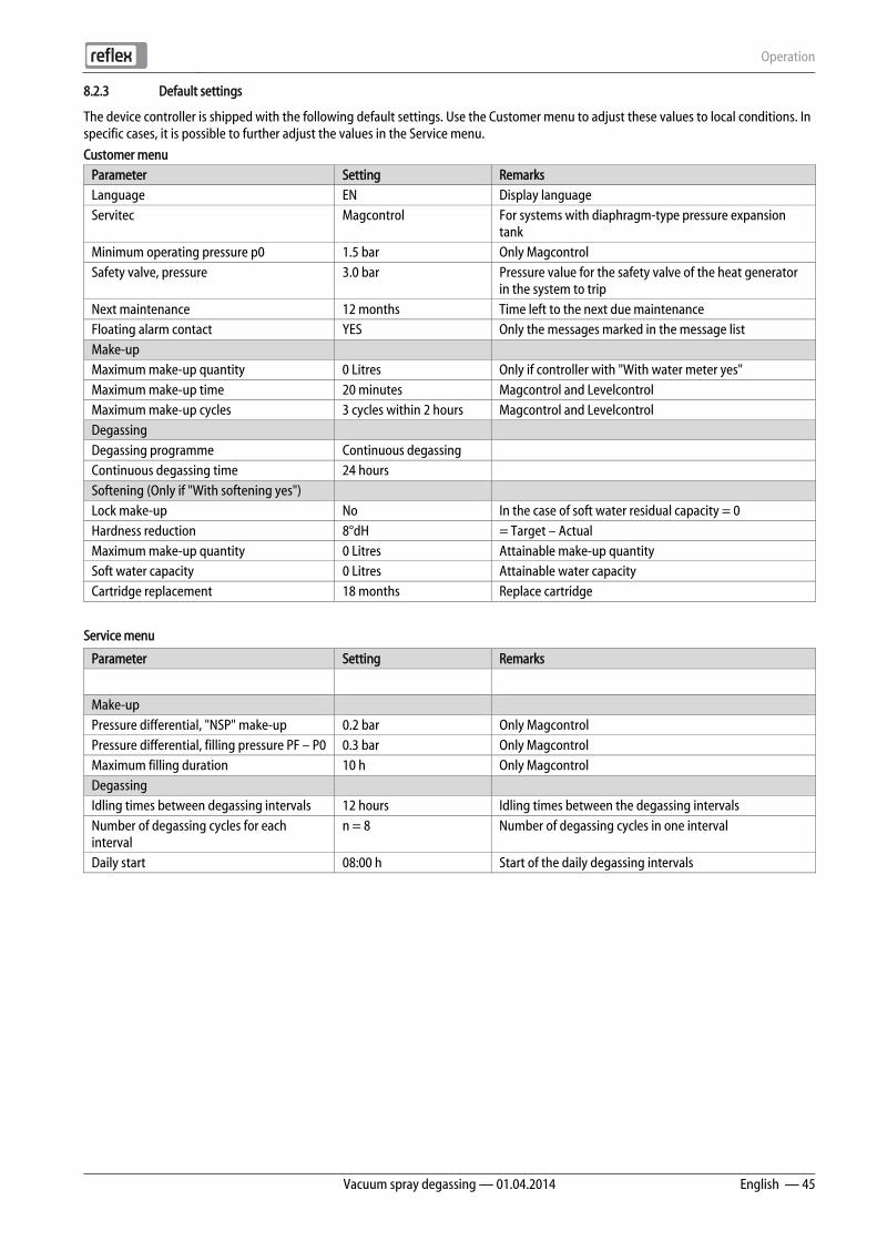
8.2.3 Default settings
The device controller is shipped with the following default settings. Use the Customer menu to adjust these values to local conditions. In specific cases, it is possible to further adjust the values in the Service menu.
Customer menu Parameter Setting Remarks Language EN Display language Servitec Magcontrol For systems with diaphragm-type pressure expansion
tank Minimum operating pressure p0 1.5 bar Only Magcontrol Safety valve, pressure 3.0 bar Pressure value for the safety valve of the heat generator
in the system to trip Next maintenance 12 months Time left to the next due maintenance Floating alarm contact YES Only the messages marked in the message list Make-up Maximum make-up quantity 0 Litres Only if controller with "With water meter yes" Maximum make-up time 20 minutes Magcontrol and Levelcontrol Maximum make-up cycles 3 cycles within 2 hours Magcontrol and Levelcontrol Degassing Degassing programme Continuous degassing Continuous degassing time 24 hours Softening (Only if "With softening yes") Lock make-up No In the case of soft water residual capacity = 0 Hardness reduction 8°dH = Target – Actual Maximum make-up quantity 0 Litres Attainable make-up quantity Soft water capacity 0 Litres Attainable water capacity Cartridge replacement 18 months Replace cartridge
Service menu
Parameter Setting Remarks
Make-up Pressure differential, "NSP" make-up 0.2 bar Only Magcontrol Pressure differential, filling pressure PF – P0 0.3 bar Only Magcontrol Maximum filling duration 10 h Only Magcontrol Degassing Idling times between degassing intervals 12 hours Idling times between the degassing intervals Number of degassing cycles for each interval
n = 8 Number of degassing cycles in one interval
Daily start 08:00 h Start of the daily degassing intervals
Operation
46 — English Vacuum spray degassing — 01.04.2014
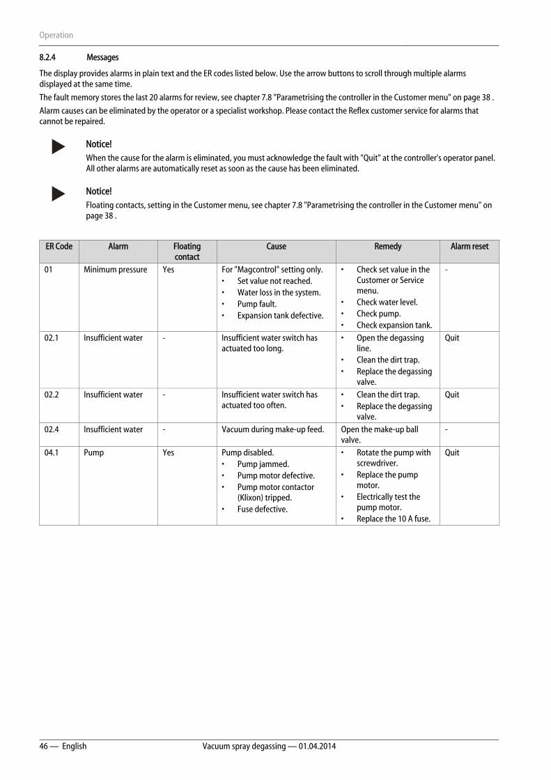
8.2.4 Messages
The display provides alarms in plain text and the ER codes listed below. Use the arrow buttons to scroll through multiple alarms displayed at the same time.
The fault memory stores the last 20 alarms for review, see chapter 7.8 "Parametrising the controller in the Customer menu" on page 38 .
Alarm causes can be eliminated by the operator or a specialist workshop. Please contact the Reflex customer service for alarms that cannot be repaired.
Notice! When the cause for the alarm is eliminated, you must acknowledge the fault with "Quit" at the controller's operator panel. All other alarms are automatically reset as soon as the cause has been eliminated.
Notice! Floating contacts, setting in the Customer menu, see chapter 7.8 "Parametrising the controller in the Customer menu" on page 38 .
ER Code Alarm Floating contact
Cause Remedy Alarm reset
01 Minimum pressure Yes For "Magcontrol" setting only. • Set value not reached. • Water loss in the system. • Pump fault. • Expansion tank defective.
• Check set value in the Customer or Service menu.
• Check water level. • Check pump. • Check expansion tank.
-
02.1 Insufficient water - Insufficient water switch has actuated too long.
• Open the degassing line.
• Clean the dirt trap. • Replace the degassing
valve.
Quit
02.2 Insufficient water - Insufficient water switch has actuated too often.
• Clean the dirt trap. • Replace the degassing
valve.
Quit
02.4 Insufficient water - Vacuum during make-up feed. Open the make-up ball valve.
-
04.1 Pump Yes Pump disabled. • Pump jammed. • Pump motor defective. • Pump motor contactor
(Klixon) tripped. • Fuse defective.
• Rotate the pump with screwdriver.
• Replace the pump motor.
• Electrically test the pump motor.
• Replace the 10 A fuse.
Quit

Operation
Vacuum spray degassing — 01.04.2014 English — 47
ER Code Alarm Floating contact
Cause Remedy Alarm reset
06 Make-up time - • Set value exceeded. • Water loss in the system. • Make-up line not
connected. • Make-up rate insufficient. • Make-up hysteresis too
low.
• Check set value in the Customer or Service menu.
• Check water level. • Connect make-up
line.
Quit
07 Make-up cycles - Set value exceeded. • Check set value in the Customer or Service menu.
• Seal the leak in the system.
Quit
08 Pressure measurement
- For "Magcontrol" setting only. • Controller receives
incorrect signal.
• Connect the plug. • Check the cable for
damage. • Check the pressure
transducer.
Quit
10 Maximum pressure - For "Magcontrol" setting only. • Set value exceeded.
• Check set value in the Customer or Service menu.
• Set the tripping pressure of the safety valve.
-
11 Back-up volume - "With water meter" must be activated in the Customer menu. • Set value exceeded. • Severe water loss in the
system.
• Check set value in the Customer or Service menu.
• Check the water loss and correct, if necessary.
Quit
14 Discharge period - • Set value exceeded. • "DC" degassing line closed. • Dirt trap clogged.
• Check set value in the Customer or Service menu.
• Open the degassing line.
• Clean the dirt trap.
Quit
15 Back-up valve - Contact water meter measures without make-up request.
Check the 3-ways motor ball valve for leaks.
Quit
16 Power failure - No power. Connect to power. -

Operation
48 — English Vacuum spray degassing — 01.04.2014
ER Code Alarm Floating contact Cause Remedy Alarm reset
19 Stop ˃ 4 hours - Device is in stop mode for more than 4 hours.
Set the controller to Automatic mode.
-
20 Maximum make-up quantity
- Set value exceeded. Reset the "Make-up quantity" meter in the Customer menu.
Quit
21 Maintenance recommendation
- Set value exceeded. Carry out maintenance. Quit
24 Softening - • Set value for soft water capacity exceeded.
• Time interval for replacement of the softening cartridge exceeded.
Replace the softening cartridges.
Quit
30 I/O module fault - • I/O module defective. • Connection between
option card and controller faulty.
• Option card defective.
• Replace the I/O module.
• Check the connection between option card and controller.
• Replace the option card.
-
31 EEPROM defective Yes • EEPROM defective. • Internal calculation error.
Contact the Reflex Customer Service.
Quit
32 Undervoltage Yes Supply voltage not achieved. Check power supply. -
33 Adjustment parameter faulty
- EPROM parameter memory defective.
Contact the Reflex Customer Service.
Quit
34 Main board communication faulty
- • Connecting cable defective.
• Main board defective.
Contact the Reflex Customer Service.
Quit
35 Digital input voltage faulty
- Short-circuit of input voltage. Check the wiring at the digital inputs (water meter, for example).
-
36 Analogue input voltage faulty
- Short-circuit of input voltage. Check the wiring at the analogue inputs (pressure/level).
-
37 No input voltage for the 3-ways motor ball valve
- Short-circuit of input voltage. Check the wiring at the 3-ways motor ball valve.
-
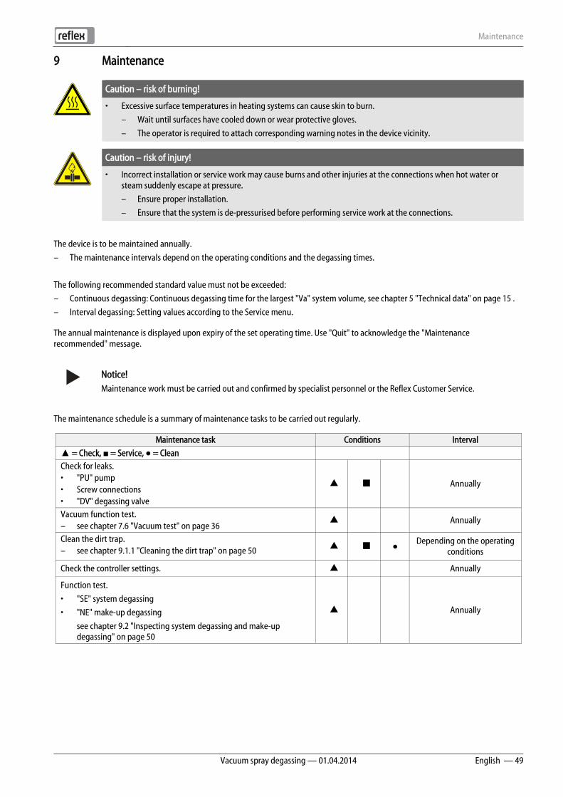
Maintenance
Vacuum spray degassing — 01.04.2014 English — 49
9 Maintenance
Caution – risk of burning!
• Excessive surface temperatures in heating systems can cause skin to burn.
– Wait until surfaces have cooled down or wear protective gloves.
– The operator is required to attach corresponding warning notes in the device vicinity.
Caution – risk of injury!
• Incorrect installation or service work may cause burns and other injuries at the connections when hot water or steam suddenly escape at pressure.
– Ensure proper installation.
– Ensure that the system is de-pressurised before performing service work at the connections.
The device is to be maintained annually.
– The maintenance intervals depend on the operating conditions and the degassing times.
The following recommended standard value must not be exceeded:
– Continuous degassing: Continuous degassing time for the largest "Va" system volume, see chapter 5 "Technical data" on page 15 .
– Interval degassing: Setting values according to the Service menu.
The annual maintenance is displayed upon expiry of the set operating time. Use "Quit" to acknowledge the "Maintenance recommended" message.
Notice! Maintenance work must be carried out and confirmed by specialist personnel or the Reflex Customer Service.
The maintenance schedule is a summary of maintenance tasks to be carried out regularly.
Maintenance task Conditions Interval
▲ = Check, ■ = Service, ● = Clean
Check for leaks. • "PU" pump • Screw connections • "DV" degassing valve
▲ ■ Annually
Vacuum function test. – see chapter 7.6 "Vacuum test" on page 36
▲ Annually
Clean the dirt trap. – see chapter 9.1.1 "Cleaning the dirt trap" on page 50 ▲ ■ ●
Depending on the operating conditions
Check the controller settings. ▲ Annually
Function test.
• "SE" system degassing
• "NE" make-up degassing
see chapter 9.2 "Inspecting system degassing and make-up degassing" on page 50
▲ Annually

Maintenance
50 — English Vacuum spray degassing — 01.04.2014
9.1 Cleaning
9.1.1 Cleaning the dirt trap
The "ST" dirt trap in the "DC" degassing line must be cleaned after the expiry of the continuous degassing time at the latest. Check the dirt traps after every filling action or extended operation.
1. Press "Stop" on the controller's operator panel.
– The device is non-functioning and the "PU" pump is shut down.
2. Close the ball valve upstream of the "ST" (1) dirt trap.
3. Slowly unscrew the cap with the dirt trap insert at the dirt trap to release any residual pressure in the pipeline section.
4. Pull the mesh from the cap and rinse it with clear water. Use a soft brush for cleaning.
5. Re-insert the mesh into the cap, check the gasket for damage, and screw the cap back into the housing of the "ST" (1) dirt trap.
6. Open the ball valve upstream of the "ST" (1) dirt trap.
7. Press "Auto" on the controller's operator panel.
– The device is switched on and the "PU" pump is in operation.
Notice! Clean all other installed dirt traps (in the Fillset, for example).
9.2 Inspecting system degassing and make-up degassing
Inspect the "SE" system degassing followed by the "NE" make-up degassing.
Press "Manual" at the controller to switch to manual mode. The Auto LED at the operator panel flashes to visually indicate that manual mode is active. Manually activate or deactivate the "SE" system degassing and the "NE" make-up degassing.
You should run at least ten cycles each in the "SE" and the "NE" modes. The gas must be eliminated before the next cycle starts. Subsequently, check the following conditions:
• With cold water, the "PI" vacuum gauge must eventually show a value of approx. -1 bar.
• The "Insufficient water" message must not be displayed at the controller.
After the inspection is completed, reset the device to Automatic mode.
• "Next" and "Back" buttons
– Selecting "NE" or "SE".
• "Auto" button
– Return to Automatic mode.
2.5 bar NE▼* SE▲* 010 h
* Flashing mode "NE▼“ or "SE▲“ is activated
1
Maintenance
Vacuum spray degassing — 01.04.2014 English — 51
9.3 Maintenance certificate
All maintenance tasks have been completed according to the Reflex Installation, Operating and Maintenance Manual.
Date Service organisation Signature Remarks

Maintenance
52 — English Vacuum spray degassing — 01.04.2014
9.4 Inspection
9.4.1 Pressure-bearing components
Comply with all applicable national regulations for the operation of pressure equipment. De-pressurise all pressurised components prior to inspection (see disassembly information).
9.4.2 Inspection prior to commissioning
In Germany, follow the Industrial Safety Regulation [Betriebssicherheitsverordnung] Section 14 and Section 14 (3) No. 6 in particular. This regulation demands an inspection prior to commissioning only for PS∙V > 50 bar x litres. This is not the case with this device. Customised systems with special spray tubes may be affected, in which case the shipping documents will contain a corresponding note.
9.4.3 Inspection intervals
Recommended maximum inspection intervals for operation in Germany pursuant to Section 15 of the Industrial Safety Regulation [Betriebssicherheitsverordnung] and the vessel classification of the device in diagram 2 of the EU Directive 97/23/EC, applicable in strict compliance with the Reflex Installation, Operation and Maintenance Manual.
External inspection:
No requirement according to Section 15 (6).
Internal inspection:
Maximum interval according to Section § 15 (5); if necessary, suitable replacement actions are to be taken (such as wall thickness measurement and comparison with the design specification which may be requested from the manufacturer)..
Tightness test:
Maximum interval according to Section 15 (5), possibly in conjunction with Section 15 (10).
Furthermore, compliance with Section 15 of the Industrial Safety Regulation and Section 15 (1) in particular, in conjunction with Section 14 (3) No. 6 and Section 15 (6), must be ensured.
The actual intervals must be determined by the user on the basis of a safety-technical assessment taking into account the real operational conditions, the experience with the operation and the charging material, and the national regulations for the operation of pressure equipment.
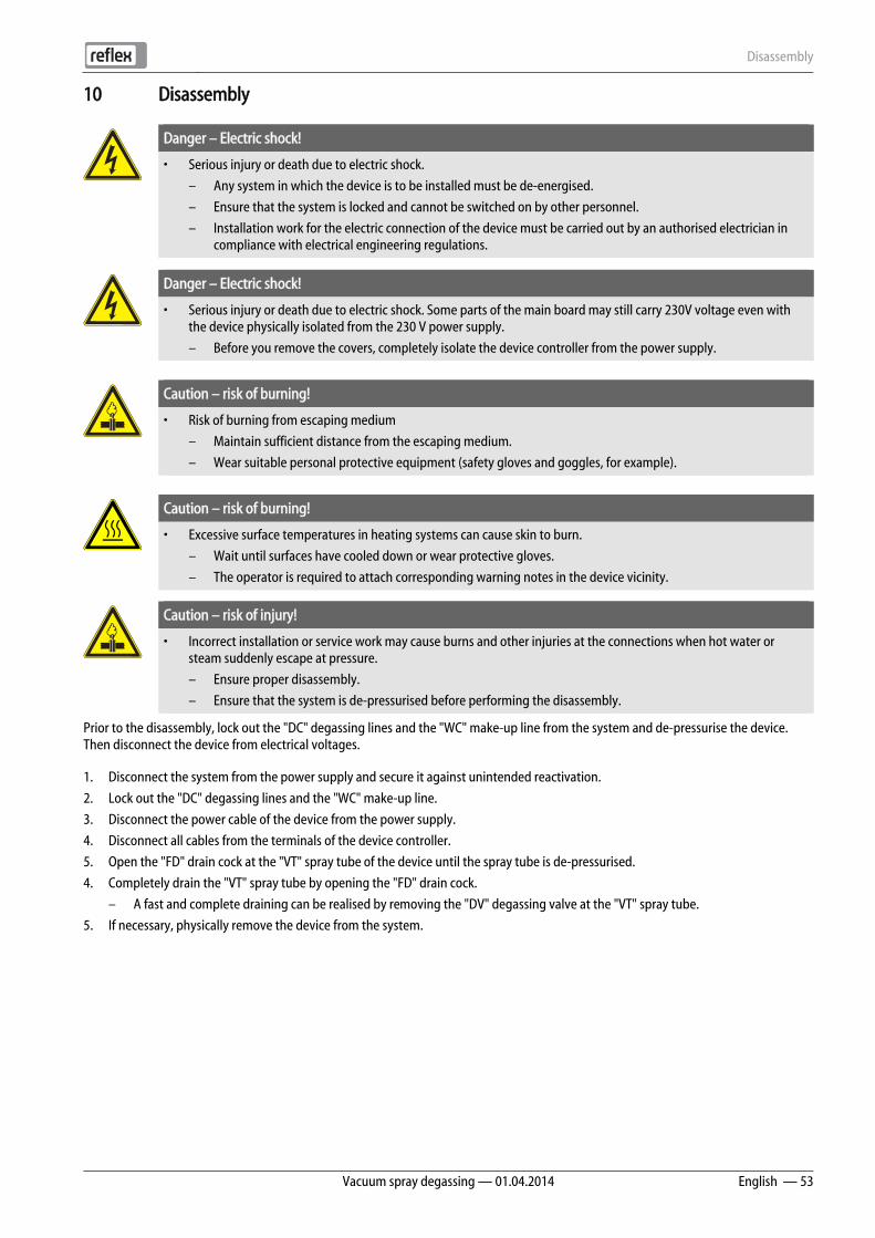
Disassembly
Vacuum spray degassing — 01.04.2014 English — 53
10 Disassembly
Danger – Electric shock!
• Serious injury or death due to electric shock.
– Any system in which the device is to be installed must be de-energised.
– Ensure that the system is locked and cannot be switched on by other personnel.
– Installation work for the electric connection of the device must be carried out by an authorised electrician in compliance with electrical engineering regulations.
Danger – Electric shock!
• Serious injury or death due to electric shock. Some parts of the main board may still carry 230V voltage even with the device physically isolated from the 230 V power supply.
– Before you remove the covers, completely isolate the device controller from the power supply.
Caution – risk of burning!
• Risk of burning from escaping medium
– Maintain sufficient distance from the escaping medium.
– Wear suitable personal protective equipment (safety gloves and goggles, for example).
Caution – risk of burning!
• Excessive surface temperatures in heating systems can cause skin to burn.
– Wait until surfaces have cooled down or wear protective gloves.
– The operator is required to attach corresponding warning notes in the device vicinity.
Caution – risk of injury!
• Incorrect installation or service work may cause burns and other injuries at the connections when hot water or steam suddenly escape at pressure.
– Ensure proper disassembly.
– Ensure that the system is de-pressurised before performing the disassembly.
Prior to the disassembly, lock out the "DC" degassing lines and the "WC" make-up line from the system and de-pressurise the device. Then disconnect the device from electrical voltages.
1. Disconnect the system from the power supply and secure it against unintended reactivation.
2. Lock out the "DC" degassing lines and the "WC" make-up line.
3. Disconnect the power cable of the device from the power supply.
4. Disconnect all cables from the terminals of the device controller.
5. Open the "FD" drain cock at the "VT" spray tube of the device until the spray tube is de-pressurised.
4. Completely drain the "VT" spray tube by opening the "FD" drain cock.
– A fast and complete draining can be realised by removing the "DV" degassing valve at the "VT" spray tube.
5. If necessary, physically remove the device from the system.
Annex
54 — English Vacuum spray degassing — 01.04.2014
11 Annex 11.1 Reflex Customer Service
Central customer service
Switchboard: Telephone number: +49 (0)2382 7069 - 0
Customer Service extension: +49 (0)2382 7069 - 9505
Fax: +49 (0)2382 7069 - 523
E-mail: [email protected]
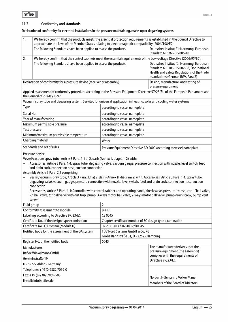
Annex
Vacuum spray degassing — 01.04.2014 English — 55
11.2 Conformity and standards
Declaration of conformity for electrical installations in the pressure maintaining, make-up or degassing systems
1. We hereby confirm that the products meets the essential protection requirements as established in the Council Directive to approximate the laws of the Member States relating to electromagnetic compatibility (2004/108/EC).
The following Standards have been applied to assess the products: Deutsches Institut für Normung, European Standard 61326 – 1:2006-10
2. We hereby confirm that the control cabinets meet the essential requirements of the Low-voltage Directive (2006/95/EC). The following Standards have been applied to assess the products: Deutsches Institut für Normung, European
Standard 61010 – 1:2002-08, Occupational Health and Safety Regulations of the trade associations (German BGV, Para 2)
Declaration of conformity for a pressure device (receiver or assembly) Design, manufacture, and testing of pressure equipment
Applied assessment of conformity procedure according to the Pressure Equipment Directive 97/23/EU of the European Parliament and the Council of 29 May 1997 Vacuum spray tube and degassing system: Servitec for universal application in heating, solar and cooling water systems Type according to vessel nameplate
Serial No. according to vessel nameplate Year of manufacturing according to vessel nameplate Maximum permissible pressure according to vessel nameplate Test pressure according to vessel nameplate Minimum/maximum permissible temperature according to vessel nameplate Charging material Water
Standards and set of rules Pressure Equipment Directive AD 2000 according to vessel nameplate
Pressure device: Vessel/vacuum spray tube, Article 3 Para. 1.1 a) 2. dash (Annex II, diagram 2) with: – Accessories, Article 3 Para. 1.4: Spray tube, degassing valve, vacuum gauge, pressure connection with nozzle, level switch, feed
and drain cock, connection hose, suction connection. Assembly Article 3 Para. 2.2 comprising: – Vessel/vacuum spray tube, Article 3 Para. 1.1 a) 2. dash (Annex II, diagram 2) with: Accessories, Article 3 Para. 1.4: Spray tube,
degassing valve, vacuum gauge, pressure connection with nozzle, level switch, feed and drain cock, connection hose, suction connection.
– Accessories, Article 3 Para. 1.4: Controller with control cabinet and operating panel, check valve, pressure transducer, 1"ball valve, ½“ ball valve, ½“ ball valve with dirt trap, pump, 3-ways motor ball valve, 2-ways motor ball valve, pump drain screw, pump vent screw.
Fluid group 2 Conformity assessment to module B + D Labelling according to Directive 97/23/EC CE 0045 Certificate No. of the design type examination Chapter certificate number of EC design type examination Certificate No., QA system (Module D) 07 202 1403 Z 0250/12/D0045 Notified body for the assessment of the QA system TÜV Nord Systems GmbH & Co. KG
Große Bahnstraße 31, D - 22525 Hamburg Register No. of the notified body 0045
Manufacturer
Reflex Winkelmann GmbH
Gersteinstraße 19
D - 59227 Ahlen - Germany
Telephone: +49 (0)2382 7069-0
Fax: +49 (0)2382 7069-588
E-mail: [email protected]
The manufacturer declares that the pressure equipment (the assembly) complies with the requirements of Directive 97/23/EC.
Norbert Hülsmann / Volker Mauel
Members of the Board of Directors

Annex
56 — English Vacuum spray degassing — 01.04.2014
11.3 Certificate No. of the design type examination
Type Certificate number Reflexomat Compact RC 200 – 500 litres 6 bar – 120 °C 04 202 1 450 04 01952 Reflexomat RS 200 – 800 litres 6 bar – 120 °C 04 202 1 932 01 00077 1000 – 5000 litres 6 bar – 120 °C 04 202 1 450 02 00714 350 – 5000 litres 10 bar – 120 °C 04 202 1 450 02 00039 1000 – 5000 litres 10 bar – 120 °C 04 202 1 450 02 00715 Variomat 200 – 1000 litres 10 bar – 120 °C 04 202 1 932 01 00051 1000 – 5000 litres 10 bar – 120 °C 04 202 1 450 02 00712 Gigamat 1000 – 5000 litres 10 bar – 120 °C 04 202 1 450 02 00713 10000 Litres 10 bar – 120 °C 04 202 1 450 02 00062 Servitec DN 150 - DN 250 10 bar/16 bar – 120 °C 04 202 1 450 03 00210
Annex
Vacuum spray degassing — 01.04.2014 English — 57
11.4 Guarantee
The respective statutory guarantee regulations apply.
11.5 Glossary
Hysteresis Delayed behaviour of an output variable relative to the input variable. (The input signal influences the output signal)
Cavitation Formation and dissolution of vapour-filled cavities (vapour bubbles) in fluids. Cumulated Cumulation of values. Klixon Pressure safety cut-out for the protection of the pump motor. Permeation Process in which a substance (permeate) penetrates or migrates through a solid body.


SI14
14en
/ 91
2500
2 / 0
4-14
Reflex Winkelmann GmbH Gersteinstraße 19 59227 Ahlen, Germany Telefon: +49 (0)2382 7069-0 Telefax: +49 (0)2382 7069-588 www.reflex.de