Embed Size (px)
Citation preview
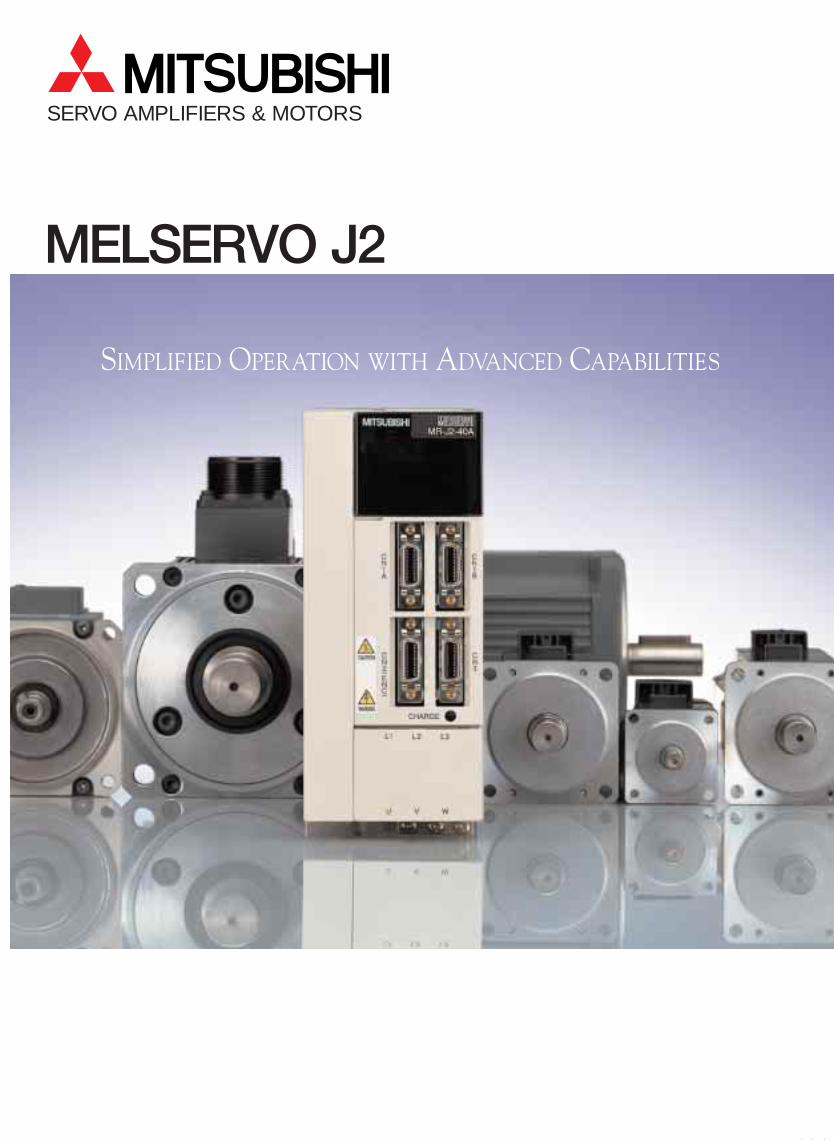
SERVO AMPLIFIERS & MOTORS
MELSERVO J2
SIMPLIFIED OPERATION WITH ADVANCED CAPABILITIES
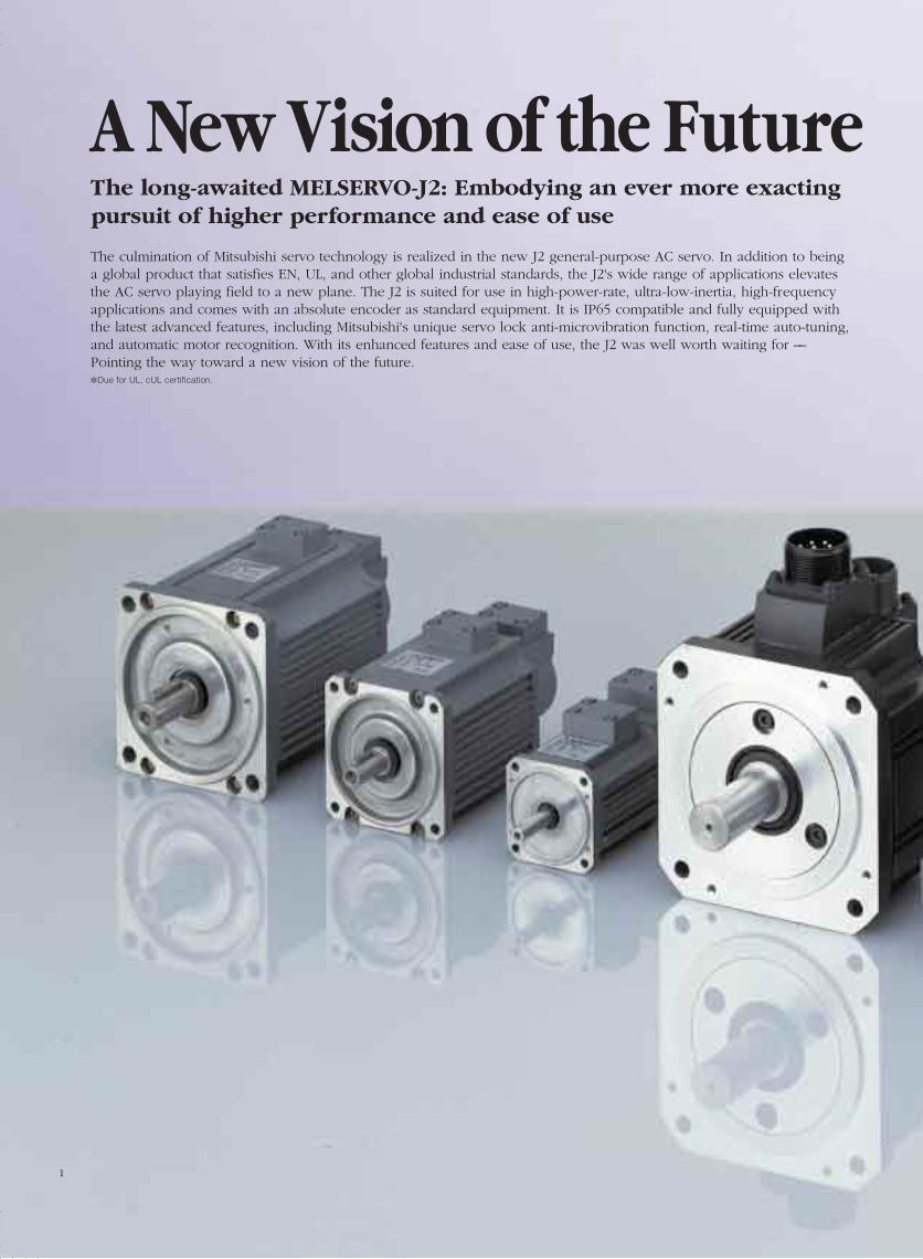
The long-awaited MELSERVO-J2: Embodying an ever more exactingpursuit of higher performance and ease of use
The culmination of Mitsubishi servo technology is realized in the new J2 general-purpose AC servo. In addition to beinga global product that satisfies EN, UL, and other global industrial standards, the J2's wide range of applications elevatesthe AC servo playing field to a new plane. The J2 is suited for use in high-power-rate, ultra-low-inertia, high-frequencyapplications and comes with an absolute encoder as standard equipment. It is IP65 compatible and fully equipped withthe latest advanced features, including Mitsubishi's unique servo lock anti-microvibration function, real-time auto-tuning,and automatic motor recognition. With its enhanced features and ease of use, the J2 was well worth waiting for ––Pointing the way toward a new vision of the future.Due for UL, cUL certification.
A New Vision of the Future
1
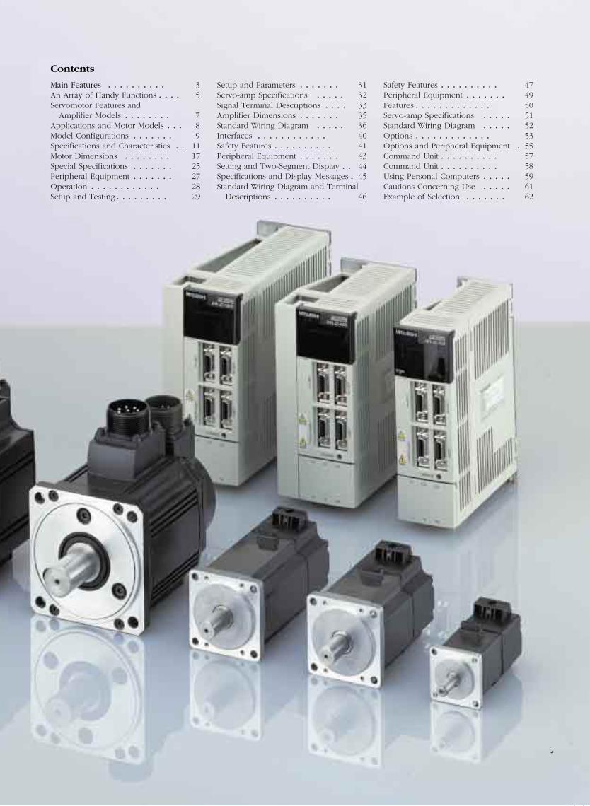
Contents
2
Main Features . . . . . . . . . . 3An Array of Handy Functions . . . . 5Servomotor Features and
Amplifier Models . . . . . . . . 7Applications and Motor Models . . . 8Model Configurations . . . . . . . 9Specifications and Characteristics . . 11Motor Dimensions . . . . . . . . 17Special Specifications . . . . . . . 25Peripheral Equipment . . . . . . . 27Operation . . . . . . . . . . . . 28Setup and Testing. . . . . . . . . 29
Setup and Parameters . . . . . . . 31Servo-amp Specifications . . . . . 32Signal Terminal Descriptions . . . . 33Amplifier Dimensions . . . . . . . 35Standard Wiring Diagram . . . . . 36Interfaces . . . . . . . . . . . . 40Safety Features . . . . . . . . . . 41Peripheral Equipment . . . . . . . 43Setting and Two-Segment Display . . 44Specifications and Display Messages . 45Standard Wiring Diagram and Terminal
Descriptions . . . . . . . . . . 46
Safety Features . . . . . . . . . . 47Peripheral Equipment . . . . . . . 49Features . . . . . . . . . . . . . 50Servo-amp Specifications . . . . . 51Standard Wiring Diagram . . . . . 52Options . . . . . . . . . . . . . 53Options and Peripheral Equipment . 55Command Unit . . . . . . . . . . 57Command Unit . . . . . . . . . . 58Using Personal Computers . . . . . 59Cautions Concerning Use . . . . . 61Example of Selection . . . . . . . 62
Main Features
Enhanced safety and ability to withstand environmental hazards
Loaded with flexible functions
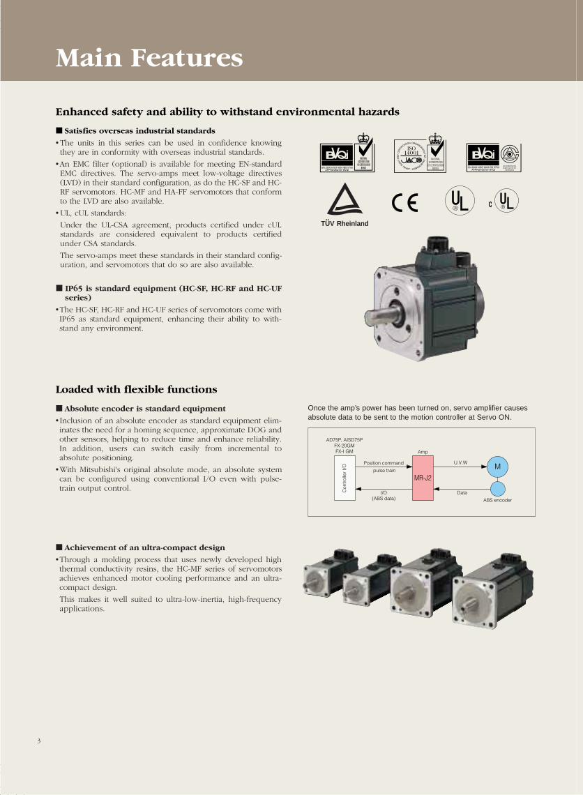
Satisfies overseas industrial standards
• The units in this series can be used in confidence knowingthey are in conformity with overseas industrial standards.
•An EMC filter (optional) is available for meeting EN-standardEMC directives. The servo-amps meet low-voltage directives(LVD) in their standard configuration, as do the HC-SF and HC-RF servomotors. HC-MF and HA-FF servomotors that conformto the LVD are also available.
• UL, cUL standards:
Under the UL-CSA agreement, products certified under cULstandards are considered equivalent to products certifiedunder CSA standards.
The servo-amps meet these standards in their standard config-uration, and servomotors that do so are also available.
IP65 is standard equipment (HC-SF, HC-RF and HC-UFseries)
•The HC-SF, HC-RF and HC-UF series of servomotors come withIP65 as standard equipment, enhancing their ability to with-stand any environment.
Absolute encoder is standard equipment
• Inclusion of an absolute encoder as standard equipment elim-inates the need for a homing sequence, approximate DOG andother sensors, helping to reduce time and enhance reliability.In addition, users can switch easily from incremental toabsolute positioning.
•With Mitsubishi's original absolute mode, an absolute systemcan be configured using conventional I/O even with pulse-train output control.
Achievement of an ultra-compact design
•Through a molding process that uses newly developed highthermal conductivity resins, the HC-MF series of servomotorsachieves enhanced motor cooling performance and an ultra-compact design.
This makes it well suited to ultra-low-inertia, high-frequencyapplications.
MU.V.W
I/O(ABS data)
Data
ABS encoder
Amp
Position command
pulse train
AD75P, AISD75PFX-20GMFX-I GM
Con
trol
ler
I/O
MR-J2
Once the amp’s power has been turned on, servo amplifier causesabsolute data to be sent to the motion controller at Servo ON.
RheinlandTUV
R R
NATIONALACCREDITATION
OF CERTIFICATIONBODIES
ORGANIZATION
FOR
ENVIRONMENT•JAPAN
AUDIT
AN
DC
ERTI
FICATION
3
Main Features
Handy control functions
User-friendly features
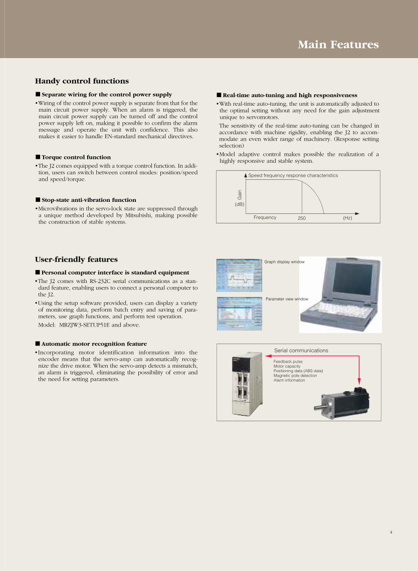
Separate wiring for the control power supply
•Wiring of the control power supply is separate from that for themain circuit power supply. When an alarm is triggered, themain circuit power supply can be turned off and the controlpower supply left on, making it possible to confirm the alarmmessage and operate the unit with confidence. This alsomakes it easier to handle EN-standard mechanical directives.
Torque control function
•The J2 comes equipped with a torque control function. In addi-tion, users can switch between control modes: position/speedand speed/torque.
Stop-state anti-vibration function
•Microvibrations in the servo-lock state are suppressed througha unique method developed by Mitsubishi, making possiblethe construction of stable systems.
Personal computer interface is standard equipment
•The J2 comes with RS-232C serial communications as a stan-dard feature, enabling users to connect a personal computer tothe J2.
•Using the setup software provided, users can display a varietyof monitoring data, perform batch entry and saving of para-meters, use graph functions, and perform test operation.
Model: MRZJW3-SETUP51E and above.
Automatic motor recognition feature
• Incorporating motor identification information into theencoder means that the servo-amp can automatically recog-nize the drive motor. When the servo-amp detects a mismatch,an alarm is triggered, eliminating the possibility of error andthe need for setting parameters.
250 (Hz)
(dB)
Speed frequency response characteristics
Frequency
Gai
n
Serial communications
Feedback pulseMotor capacityPositioning data (ABS data)Magnetic pole detectionAlarm information
Real-time auto-tuning and high responsiveness
•With real-time auto-tuning, the unit is automatically adjusted tothe optimal setting without any need for the gain adjustmentunique to servomotors.
The sensitivity of the real-time auto-tuning can be changed inaccordance with machine rigidity, enabling the J2 to accom-modate an even wider range of machinery. (Response settingselection)
•Model adaptive control makes possible the realization of ahighly responsive and stable system.
Graph display window
Parameter view window
4
An Array of Handy Functions
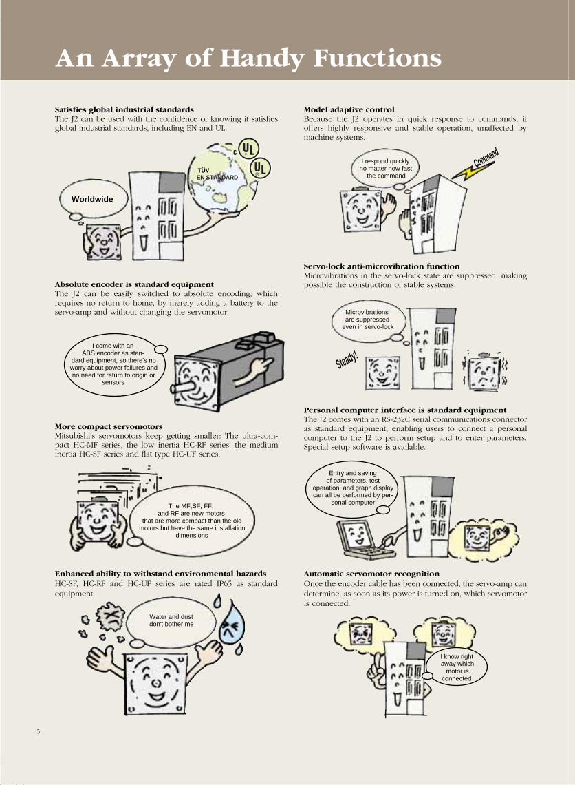
Satisfies global industrial standardsThe J2 can be used with the confidence of knowing it satisfiesglobal industrial standards, including EN and UL.
Model adaptive controlBecause the J2 operates in quick response to commands, itoffers highly responsive and stable operation, unaffected bymachine systems.
Absolute encoder is standard equipmentThe J2 can be easily switched to absolute encoding, whichrequires no return to home, by merely adding a battery to theservo-amp and without changing the servomotor.
Servo-lock anti-microvibration functionMicrovibrations in the servo-lock state are suppressed, makingpossible the construction of stable systems.
More compact servomotorsMitsubishi's servomotors keep getting smaller: The ultra-com-pact HC-MF series, the low inertia HC-RF series, the mediuminertia HC-SF series and flat type HC-UF series.
Personal computer interface is standard equipmentThe J2 comes with an RS-232C serial communications connectoras standard equipment, enabling users to connect a personalcomputer to the J2 to perform setup and to enter parameters.Special setup software is available.
Enhanced ability to withstand environmental hazardsHC-SF, HC-RF and HC-UF series are rated IP65 as standardequipment.
Automatic servomotor recognitionOnce the encoder cable has been connected, the servo-amp candetermine, as soon as its power is turned on, which servomotoris connected.
Worldwide
EN STANDARDTUV
I respond quickly no matter how fast
the command
Command
I come with an ABS encoder as stan-
dard equipment, so there's no worry about power failures and no need for return to origin or
sensors
Microvibrations are suppressed
even in servo-lock
Steady!
The MF,SF, FF, and RF are new motors
that are more compact than the old motors but have the same installation
dimensions
Entry and saving of parameters, test
operation, and graph display can all be performed by per-
sonal computer
Water and dust don't bother me
I know right away which
motor is connected
5
Easy wiring and easy setup with high-speed
SSC-NET
Coming Soon!
On/off switches and signal assignments can be changed inside me
without any wiring switch
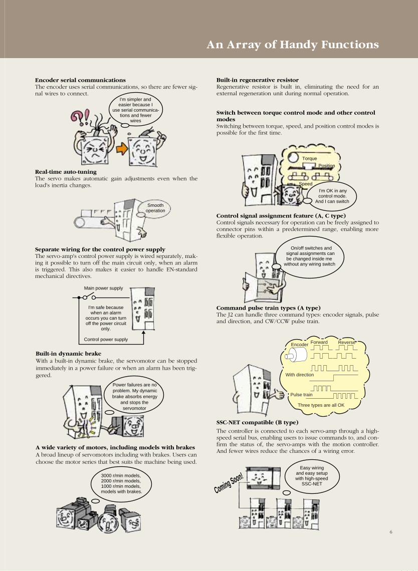
Encoder serial communicationsThe encoder uses serial communications, so there are fewer sig-nal wires to connect.
A wide variety of motors, including models with brakesA broad lineup of servomotors including with brakes. Users canchoose the motor series that best suits the machine being used.
Real-time auto-tuningThe servo makes automatic gain adjustments even when theload's inertia changes.
Built-in regenerative resistorRegenerative resistor is built in, eliminating the need for anexternal regeneration unit during normal operation.
Switch between torque control mode and other controlmodesSwitching between torque, speed, and position control modes ispossible for the first time.
Separate wiring for the control power supplyThe servo-amp's control power supply is wired separately, mak-ing it possible to turn off the main circuit only, when an alarmis triggered. This also makes it easier to handle EN-standardmechanical directives.
Control signal assignment feature (A, C type)Control signals necessary for operation can be freely assigned toconnector pins within a predetermined range, enabling moreflexible operation.
Built-in dynamic brakeWith a built-in dynamic brake, the servomotor can be stoppedimmediately in a power failure or when an alarm has been trig-gered.
Command pulse train types (A type)The J2 can handle three command types: encoder signals, pulseand direction, and CW/CCW pulse train.
SSC-NET compatible (B type)
The controller is connected to each servo-amp through a high-speed serial bus, enabling users to issue commands to, and con-firm the status of, the servo-amps with the motion controller.And fewer wires reduce the chances of a wiring error.
I'm simpler and easier because I
use serial communica-tions and fewer
wires
Smooth operation
I'm safe because when an alarm
occurs you can turn off the power circuit
only.
Control power supply
Main power supply
Power failures are no problem. My dynamic brake absorbs energy
and stops the servomotor
3000 r/min models,2000 r/min models,1000 r/min models,
models with brakes.
I'm OK in any control mode.
And I can switch
Torque
Position
Speed
Encoder Forward Reverse
With direction
Pulse train
Three types are all OK
6
An Array of Handy Functions
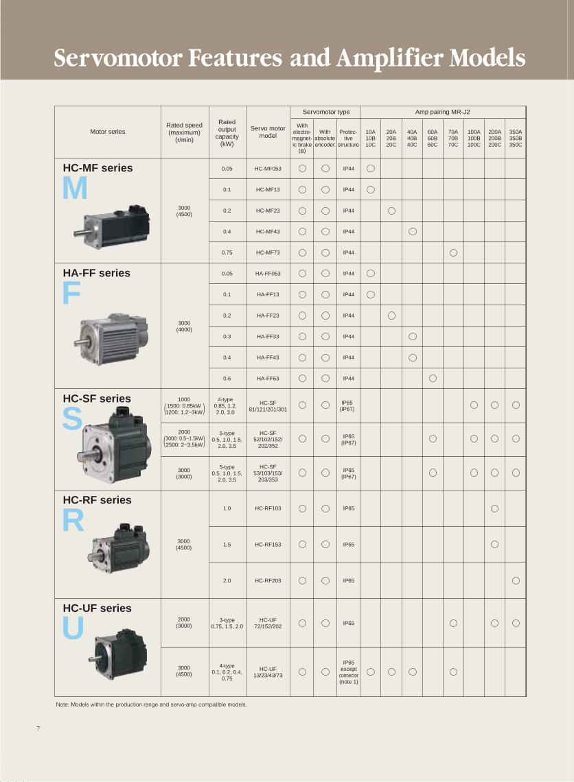
Servomotor Features and Amplifier Models
7
Servomotor type
Withabsoluteencoder
350A350B350C
200A200B200C
100A100B100C
70A70B70C
60A60B60C
40A40B40C
20A20B20C
Protec-tive
structure
10A10B10C
Withelectro-magnet-ic brake
(B)
Rated speed(maximum)
(r/min)
Ratedoutput
capacity(kW)
Servo motormodel
Amp pairing MR-J2
Motor series
HC-MF series
M
HA-FF series
F
HC-SF series
S
HC-RF series
R
HC-UF series
U
0.05 IP44HC-MF053
0.1 IP44HC-MF13
0.23000(4500)
3000(4000)
IP44HC-MF23
0.4 IP44HC-MF43
0.75 IP44HC-MF73
0.05 IP44HA-FF053
0.1 IP44HA-FF13
0.2 IP44HA-FF23
0.3 IP44HA-FF33
0.4 IP44HA-FF43
0.6 IP44HA-FF63
HC-SF81/121/201/301
HC-SF52/102/152/
202/352
HC-SF53/103/153/
203/353
4-type0.85, 1.2,2.0, 3.0
10001500: 0.85kW
1200: 1.2~3kW
IP65(IP67)
5-type0.5, 1.0, 1.5,
2.0, 3.5
IP65(IP67)
5-type0.5, 1.0, 1.5,
2.0, 3.5
3000(3000)
2000(3000)
3000(4500)
IP65(IP67)
1.0 IP65HC-RF103
1.53000
(4500)IP65HC-RF153
2.0 IP65HC-RF203
3-type0.75, 1.5, 2.0
IP65HC-UF
72/152/202
4-type0.1, 0.2, 0.4,
0.75
IP65except
connector(note 1)
HC-UF13/23/43/73
( )
20003000: 0.5~1.5kW2500: 2~3.5kW( )
Note: Models within the production range and servo-amp compatible models.
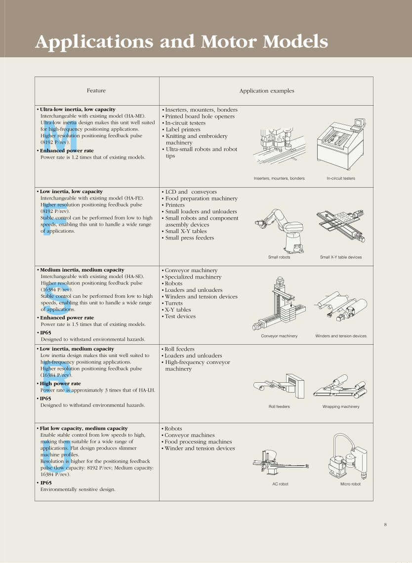
Feature Application examples
• Inserters, mounters, bonders• Printed board hole openers• In-circuit testers• Label printers• Knitting and embroidery machinery
• Ultra-small robots and robottips
• LCD and conveyors• Food preparation machinery• Printers• Small loaders and unloaders• Small robots and componentassembly devices
• Small X-Y tables• Small press feeders
• Conveyor machinery• Specialized machinery• Robots• Loaders and unloaders• Winders and tension devices• Turrets• X-Y tables• Test devices
• Roll feeders• Loaders and unloaders• High-frequency conveyormachinery
Inserters, mounters, bonders
Small robots
Conveyor machinery
Roll feeders
In-circuit testers
Small X-Y table devices
Winders and tension devices
Wrapping machinery
M
F
S
R
Applications and Motor Models
• Ultra-low inertia, low capacityInterchangeable with existing model (HA-ME).Ultra-low inertia design makes this unit well suitedfor high-frequency positioning applications.Higher resolution positioning feedback pulse(8192 P/rev).
• Enhanced power ratePower rate is 1.2 times that of existing models.
• Low inertia, low capacityInterchangeable with existing model (HA-FE).Higher resolution positioning feedback pulse(8192 P/rev).Stable control can be performed from low to highspeeds, enabling this unit to handle a wide range of applications.
• Medium inertia, medium capacityInterchangeable with existing model (HA-SE).Higher resolution positioning feedback pulse(16384 P/rev).Stable control can be performed from low to highspeeds, enabling this unit to handle a wide range of applications.
• Enhanced power ratePower rate is 1.5 times that of existing models.
• IP65Designed to withstand environmental hazards.
• Low inertia, medium capacityLow inertia design makes this unit well suited tohigh-frequency positioning applications.Higher resolution positioning feedback pulse(16384 P/rev).
• High power ratePower rate is approximately 3 times that of HA-LH.
• IP65Designed to withstand environmental hazards.
• Robots• Conveyor machines• Food processing machines• Winder and tension devicesU
• Flat low capacity, medium capacityEnable stable control from low speeds to high,making them suitable for a wide range of applications. Flat design produces slimmermachine profiles.Resolution is higher for the positioning feedbackpulse (low capacity: 8192 P/rev; Medium capacity:16384 P/rev).
• IP65Environmentally sensitive design.
8
AC robot Micro robot
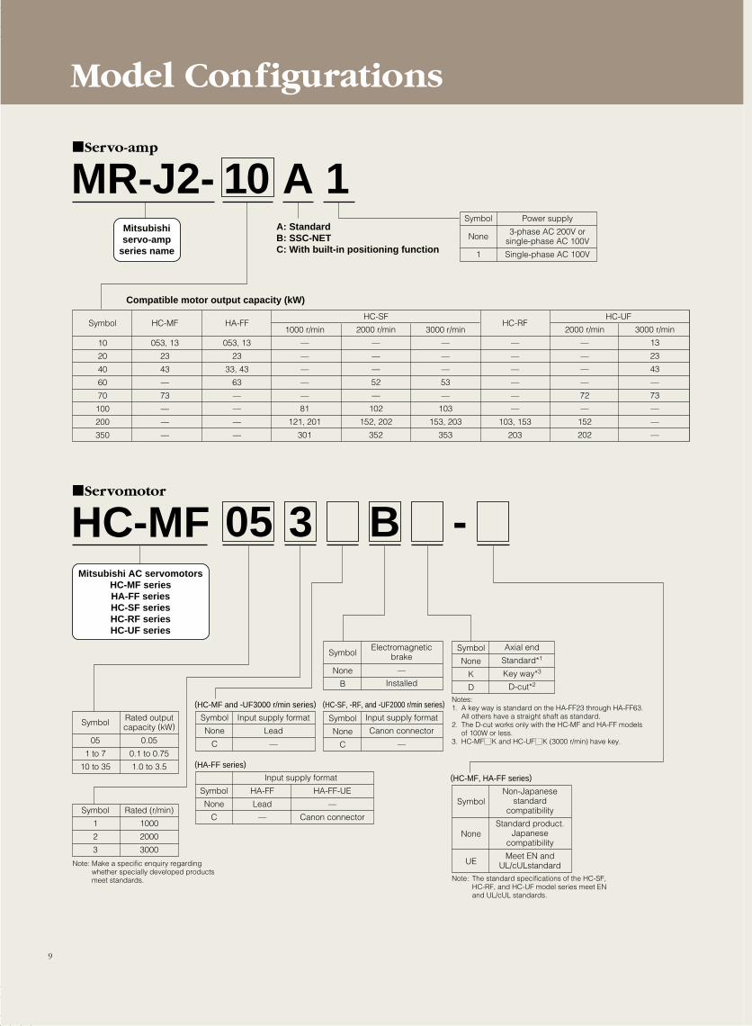
Model Configurations
9
MR-J2- 10 A 1A: StandardB: SSC-NETC: With built-in positioning function
Servo-amp
Mitsubishiservo-amp
series name
Compatible motor output capacity (kW)
HC-MFServomotor
Mitsubishi AC servomotorsHC-MF seriesHA-FF seriesHC-SF seriesHC-RF seriesHC-UF series
Symbol
05
1 to 7
10 to 35
Rated outputcapacity (kW)
0.05
0.1 to 0.75
1.0 to 3.5
05 3 B -
Symbol
1
2
3
Rated (r/min)
1000
2000
3000
Symbol
None
C
Input supply format
Lead
—
(HC-MF and -UF3000 r/min series)
Symbol
None
C
Input supply format
HA-FF
Lead
—
HA-FF-UE
—
Canon connector
(HA-FF series)
(HC-MF, HA-FF series)
Symbol
None
C
Input supply format
Canon connector
—
Symbol
None
B
Electromagneticbrake
—
Installed
(HC-SF, -RF, and -UF2000 r/min series)
Symbol
None
UE
Non-Japanesestandard
compatibility
Standard product.Japanese
compatibility
Meet EN andUL/cULstandard
Note: The standard specifications of the HC-SF, HC-RF, and HC-UF model series meet EN and UL/cUL standards.
Note: Make a specific enquiry regarding whether specially developed products meet standards.
Symbol
None
K
D
Axial end
Standard*1
Key way*3
D-cut*2
Notes:1. A key way is standard on the HA-FF23 through HA-FF63.
All others have a straight shaft as standard.2. The D-cut works only with the HC-MF and HA-FF models
of 100W or less.3. HC-MFMK and HC-UFMK (3000 r/min) have key.
Symbol
None
1
Power supply
3-phase AC 200V orsingle-phase AC 100V
Single-phase AC 100V
Symbol
10
20
40
60
70
100
200
350
HC-MF
053, 13
23
43
—
73
—
—
—
HA-FF
053, 13
23
33, 43
63
—
—
—
—
HC-RF
—
—
—
—
—
—
103, 153
203
1000 r/min
—
—
—
—
—
81
121, 201
301
3000 r/min
—
—
—
53
—
103
153, 203
353
HC-SF
2000 r/min
—
—
—
52
—
102
152, 202
352
2000 r/min
—
—
—
—
72
—
152
202
3000 r/min
13
23
43
—
73
—
—
—
HC-UF
10
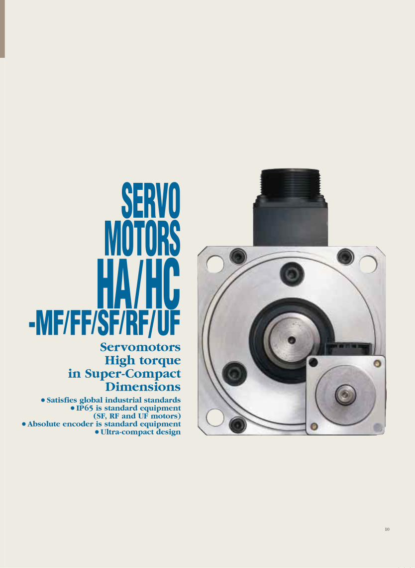
SERVOMOTORSHA/HC
-MF/FF/SF/RF/UFServomotors High torque
in Super-Compact Dimensions
• Satisfies global industrial standards• IP65 is standard equipment
(SF, RF and UF motors)•Absolute encoder is standard equipment
•Ultra-compact design
11
Notes:1. The power facility capacity varies depending on the power supply's impedance.2. The figures for regeneration braking frequency indicate the permissible frequency when the motor alone decelerates to a stop from the rated rotation speed. When load is applied, regenera-
tion braking frequency is 1/(m+1) of the figure in the table (m = load's moment of inertia/motor's moment of inertia). When the rated rotation speed is exceeded, braking frequency is in inverseproportion to the square of operating speed divided by rated speed. When the operating rotation speed is frequently changing, or when a continuous regeneration condition exists, such asduring vertical feed, assess the regeneration heat (W) generated during operation and make sure that it does not exceed the permissible range.
3. There are no limits on regeneration frequency as long as the effective torque is within the rated torque range. However, the load/motor of inertia ratio must be 30 or less.4. Contact Mitsubishi if the load/motor of inertia ratio exceeds the figure in the table.5. The vibration direction is shown in this diagram.6. Excluding the shaft-through section and connectors.
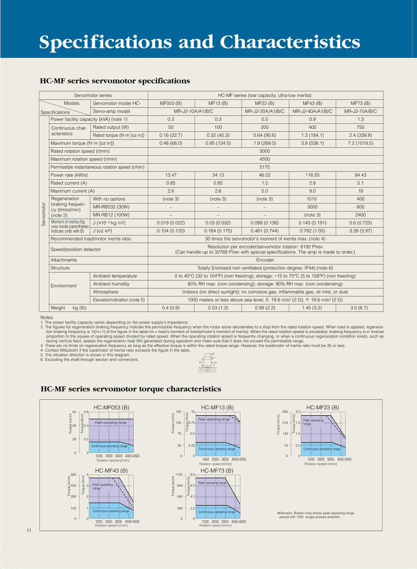
Servomotor series HC-MF series (low capacity, ultra-low inertia)
Servomotor model HC- MF053 (B) MF13 (B) MF23 (B) MF43 (B) MF73 (B)
Servo-amp model MR-J2-10A/A1/B/C MR-J2-20A/A1/B/C MR-J2-40A/A1/B/C MR-J2-70A/B/C
Power facility capacity (kVA) (note 1) 0.3 0.3 0.5 0.9 1.3
Rated output (W) 50 100 200 400 750
Rated torque (N.m [oz.in]) 0.16 (22.7) 0.32 (45.3) 0.64 (90.6) 1.3 (184.1) 2.4 (339.8)
Maximum torque (N.m [oz.in]) 0.48 (68.0) 0.95 (134.5) 1.9 (269.0) 3.8 (538.1) 7.2 (1019.5)
Rated rotation speed (r/min) 3000
Maximum rotation speed (r/min) 4500
Permissible instantaneous rotation speed (r/min) 5175
Power rate (kW/s) 13.47 34.13 46.02 116.55 94.43
Rated current (A) 0.85 0.85 1.5 2.8 5.1
Maximum current (A) 2.6 2.6 5.0 9.0 18
With no options (note 3) (note 3) (note 3) 1010 400
MR-RB032 (30W) – – – 3000 600
MR-RB12 (100W) – – – (note 3) 2400
J (×10-4 kg.m2) 0.019 (0.022) 0.03 (0.032) 0.088 (0.136) 0.143 (0.191) 0.6 (0.725)
J (oz.in2) 0.104 (0.120) 0.164 (0.175) 0.481 (0.744) 0.782 (1.05) 3.28 (3.97)
Recommended load/motor inertia ratio 30 times the servomotor's moment of inertia max. (note 4)
Speed/position detector Resolution per encoder/servomotor rotation: 8192 P/rev(Can handle up to 32768 P/rev with special specifications. The amp is made to order.)
Attachments Encoder
Structure Totally Enclosed non ventilated (protection degree: IP44) (note 6)
Ambient temperature 0 to 40°C (32 to 104°F) (non freezing), storage: −15 to 70°C (5 to 158°F) (non freezing)
Ambient humidity 80% RH max. (non condensing), storage: 90% RH max. (non condensing)
Atmosphere Indoors (no direct sunlight); no corrosive gas, inflammable gas, oil mist, or dust
Elevation/vibration (note 5) 1000 meters or less above sea level; X: 19.6 m/s2 (2 G), Y: 19.6 m/s2 (2 G)
Weight kg (lb) 0.4 (0.9) 0.53 (1.2) 0.99 (2.2) 1.45 (3.2) 3.0 (6.7)
HC-MF series servomotor specifications
Regenerationbraking frequen-cy (times/min)(note 2)Moment of inertia (fig-ures inside parenthesesindicate units with B)
Continuous char-acteristics
Specifications
Models
Ser
vom
otor
HC-MF series servomotor torque characteristics
Specifications and Characteristics
0
28
56
84
0
0.2
0.4
0.6
0
140
280
420
560
0
1
2
3
4
0
280
560
840
1120
0
2.0
4.0
6.0
8.0
HC-MF053 (B)
HC-MF43 (B) HC-MF73 (B)
0
35
70
105
140
0
0.25
0.5
0.75
10HC-MF13 (B)
0
70
140
210
280
0
0.5
1.0
1.5
2.0
1000 2000 3000 4000 4500
HC-MF23 (B)
Torq
ue (
oz• in
)
Rotation speed (r/min)
Torq
ue (
oz• in
)
Rotation speed (r/min)
Torq
ue (
oz• in
)
Rotation speed (r/min)
Torq
ue (
oz• in
)
Rotation speed (r/min)
Torq
ue (
oz• in
)
Rotation speed (r/min)
Continuous operating range
Peak operating range
Continuous operating range
Peak operating range
Continuous operating range
Peak operating range
Continuous operating range
Peak operating range
Continuous operating range
Peak operating range
Torq
ue (
N• m
)To
rque
(N
• m)
Torq
ue (
N• m
)To
rque
(N
• m)
Torq
ue (
N• m
)
1000 2000 3000 4000 45001000 2000 3000 4000 4500
1000 2000 3000 4000 4500 1000 2000 3000 4000 4500
Remarks: Broken lines shows peak operating range paired with 100V, single-phased amplifier.
Environment
XY
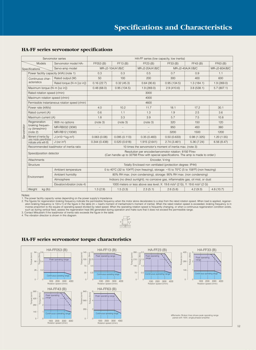
Servomotor series HA-FF series (low capacity, low inertia)
Servomotor model HA- FF053 (B) FF13 (B) FF23 (B) FF33 (B) FF43 (B) FF63 (B)
Servo-amp model MR-J2-10A/A1/B/C MR-J2-20A/A1/B/C MR-J2-40A/A1/B/C MR-J2-60A/B/C
Power facility capacity (kVA) (note 1) 0.3 0.3 0.5 0.7 0.9 1.1
Rated output (W) 50 100 200 300 400 600
Rated torque (N.m [oz.in]) 0.16 (22.7) 0.32 (45.3) 0.64 (90.6) 0.95 (134.5) 1.3 (184.1) 1.9 (269.0)
Maximum torque (N.m [oz.in]) 0.48 (68.0) 0.95 (134.5) 1.9 (269.0) 2.9 (410.6) 3.8 (538.1) 5.7 (807.1)
Rated rotation speed (r/min) 3000
Maximum rotation speed (r/min) 4000
Permissible instantaneous rotation speed (r/min) 4600
Power rate (kW/s) 4.0 10.2 11.7 18.1 17.2 30.1
Rated current (A) 0.6 1.1 1.3 1.9 2.5 3.6
Maximum current (A) 1.8 3.3 3.9 5.7 7.5 10.8
With no options (note 3) (note 3) (note 3) 320 150 120
MR-RB032 (30W) – – – 950 450 360
MR-RB12 (100W) – – – 3200 1500 1200
J (×10-4 kg.m2) 0.063 (0.08) 0.095 (0.113) 0.35 (0.483) 0.50 (0.633) 0.98 (1.325) 1.20 (1.55)
J (oz.in2) 0.344 (0.438) 0.520 (0.618) 1.915 (2.641) 2.74 (3.461) 5.36 (7.24) 6.56 (8.47)
Recommended load/motor of inertia ratio 10 times the servomotor's moment of inertia max. (note 3)
Speed/position detector Resolution per encoder/servomotor rotation: 8192 P/rev(Can handle up to 32768 P/rev with special specifications. The amp is made to order.)
Attachments Encoder, V-ring
Structure Totally Enclosed non ventilated (protection degree: IP44)
Ambient temperature 0 to 40°C (32 to 104°F) (non freezing), storage: −15 to 70°C (5 to 158°F) (non freezing)
Ambient humidity 80% RH max. (non condensing), storage: 90% RH max. (non condensing)
Atmosphere Indoors (no direct sunlight); no corrosive gas, inflammable gas, oil mist, or dust
Elevation/vibration (note 4) 1000 meters or less above sea level; X: 19.6 m/s2 (2 G), Y: 19.6 m/s2 (2 G)
Weight kg (lb) 1.3 (2.9) 1.5 (3.3) 2.3 (5.1) 2.6 (5.8) 4.2 (9.3) 4.8 (10.7)
HA-FF series servomotor specifications
Regenerationbraking frequen-cy (times/min)(note 2)
Moment of inertia (fig-ures inside parenthesesindicate units with B)
Continuous char-acteristics
Specifications
Models
Ser
vom
otor
Notes:1. The power facility capacity varies depending on the power supply's impedance.2. The figures for regeneration braking frequency indicate the permissible frequency when the motor alone decelerates to a stop from the rated rotation speed. When load is applied, regener-
ation braking frequency is 1/(m+1) of the figure in the table (m = load's moment of inertia/motor's moment of inertia). When the rated rotation speed is exceeded, braking frequency is ininverse proportion to the square of operating speed divided by rated speed. When the operating rotation speed is frequently changing, or when a continuous regeneration condition exists,such as during vertical feed, assess the regeneration heat (W) generated during operation and make sure that it does not exceed the permissible range.
3. Contact Mitsubishi if the load/motor of inertia ratio exceeds the figure in the table.4. The vibration direction is shown in this diagram.
HA-FF series servomotor torque characteristics
0 0
0.2
0.4
0.6
28
56
84HA-FF053 (B)
0 0
2
4
6
280
560
840HA-FF63 (B)
0 0
140
105
70
35
1.0
0.75
0.5
0.25
1000 2000 3000 4000
HA-FF13 (B)
0 0
560
420
280
140
4
3
2
1
HA-FF43 (B)
0 0
280
210
140
70
2.0
1.5
1.0
0.5
HA-FF23 (B)
0 0
1
2
3
140
280
420HA-FF33 (B)
Torq
ue (
oz• in
)
Rotation speed (r/min)
Torq
ue (
oz-in
)
Rotation speed (r/min)
Torq
ue (
oz• in
)
Rotation speed (r/min)
Torq
ue (
oz• in
)
Rotation speed (r/min)
Torq
ue (
oz• in
)
Torq
ue (
oz• in
)
Rotation speed (r/min) Rotation speed (r/min)
Continuous operating rangeContinuous operating range Continuous operating range Continuous operating range
Peak operating range
Continuous operating range
Peak operating range
Peak operating range
Continuous operating range
Peak operating range
Peak operating range Peak operating
range
Torq
ue (
N• m
)To
rque
(N
• m)
Torq
ue (
N• m
)To
rque
(N
• m)
Torq
ue (
N• m
)
Torq
ue (
N• m
)
1000 2000 3000 4000 1000 2000 3000 40001000 2000 3000 4000
1000 2000 3000 4000 1000 2000 3000 4000
Remarks: Broken lines shows peak operating range paired with 100V, single-phased amplifier.
XY
Environment
12
Specifications and Characteristics
13
Specifications and Characteristics
HC-SF series servomotor specifications
15 times the servomotor’s moment of inertia max. (note 3)
Encoder, oil seal
Totally Enclosed non ventilated (protection degree: IP65) (note 5)
0 to 40°C (32 to 104°F) (non freezing), storage: -15 to 70°C (5 to 158°F) (non freezing)
80% RH max. (non condensing), storage: 90% RH max. (non condensing)
Indoors (no direct sunlight); no corrosive gas, flammable gas, oil mist, or dust
1000 meters or less above sea level
X: 19.6m/s2 (2G)Y: 49m/s2 (5G)
X: 11.7m/s2 (1.2G)Y: 29.4m/s2 (3G) X: 9.8m/s2 (1G) Y: 24.5m/s2 X: 9.8m/s2 (1G)
Y: 24.5m/s2 (2.5G)
Encoder, Resolution per servomotor revolution: 16384 P/rev
HC-SF1000 r/min series (medium inertia, medium capacity)
1000 2000
3000
3450
HC-SF2000 r/min series
J2-200A/B/C
SF81 (B)
J2-100A/B/C
1.5
0.85
8.12 (1149.8)
24.4 (3455.0)
1500
1725
32.9
5.1
15.3
140
220
740
2220
—
—
20.0 (22.0)
109.0 (120.0)
9 (19.8)
SF121 (B)
2.1
1.2
11.5 (1628.4)
34.4 (4871.0)
30.9
7.1
21.3
240
—
—
—
730
1216
42.5 (52.5)
232 (287)
12 (26.5)
SF201 (B)
3.5
2.0
19.1 (2704.5)
57.3 (8113.5)
1200
1380
44.5
9.6
28.8
100
—
—
—
330
550
82.0 (92)
448 (503)
19 (41.9)
SF301 (B)
J2-350A/B/C
4.8
3.0
28.6 (4049.4)
85.9 (12163.2)
81.3
16.0
48.0
84
—
—
—
250
430
101 (111)
552 (607)
23 (50.7)
SF52 (B)
J2-60A/B/C
1.0
0.5
2.39 (338.4)
7.16 (1013.8)
8.7
3.2
9.6
56
165
560
1680
—
—
6.6 (8.6)
36.1 (47.0)
5 (11.0)
SF102 (B)
J2-100A/B/C
1.7
1.0
4.78 (676.8)
14.4 (2039.0)
16.7
6
18
54
80
270
810
—
—
13.7 (15.7)
74.9 (85.8)
7 (15.4)
Servomotor model HC-
Servo-amp model MR-
Rated output (kW)
Rated torque (N·m [oz·in])
With no options
MR-RB032 (30W)
MR-RB12 (100W)
MR-RB32 (300W)
MR-RB30 (300W)
MR-RB50 (500W)
J (×10-4 kg·m2)
J (oz·in2)
Ambient temperature
Ambient humidity
Atmosphere
Elevation
Vibration (note 4)
Moment of inertia (fig-ures inside parenthesesindicate units with B)
Continuouscharacteristics
Regenerationbrakingfrequency(items/min)(note 2)
Ser
vom
otor
Type
SpecificationsPower facility capacity (kVA) (note 1)
Mximum torque (N·m [oz·in])
Rated rotation speed (r/min)
Maximum rotation speed (r/min)
Permissible instantaneous rotation speed (r/min)
Power rate (kW/s)
Rated current (A)
Maximum current (A)
Recommended load/motor of inertia ratio
Speed/position encoder
Attachments
Structure
Environment
Weight kg (lb)
Servomotor series
Notes:1. The power supply capacity varies with the power supply impedance.2. The regenerative brake frequency shown is the permissible frequency for decelerating a stand-alone motor from rated rpm to a stop. When under load, however, the value becomes the table
value divided by (m+1) where m is the load inertial moment divided by the motor inertial moment. When the rated rpm is exceeded, the regenerative brake frequency is inversely proportional to the square of (Operating speed/rated speed). When the operating rpm varies with the frequency or when regeneration is constant (as with vertical feeds), find the regenera-tion heat generated (W) while operating and do not exceed the permissible value.
HC-SF series servomotor torque characteristics
300
500 1000 1500
200
100
0
30
20
10
0
HC-SF81 (B)
Rotation speed (r/min)
Torq
ue (
oz• in
)
Torq
ue (
N• m
)
Peak operating range
Continuous operating range
400
500 1000 1200
300
100
200
0
40
30
20
10
0
HC-SF121 (B)
Rotation speed (r/min)
Torq
ue (
oz• in
)
Torq
ue (
N• m
)
Peak operating range
Continuous operating range
600
500 1000 1200
400
200
0
60
40
20
0
HC-SF201 (B)
Rotation speed (r/min)
Torq
ue (
oz• in
)
Torq
ue (
N• m
)
Peak operating range
Continuous operating range
1000
500 1000 1200
750
500
250
0
100
75
50
25
0
HC-SF301 (B)
Rotation speed (r/min)
Torq
ue (
oz• in
)
Torq
ue (
N• m
)
Peak operating range
Continuous operating range
90
1000 2000 3000
60
30
0
9
6
3
0
HC-SF52 (B)
Rotation speed (r/min)
Torq
ue (
oz• in
)
Torq
ue (
N• m
)
Continuous operating range
Peak operating range
150
1000 2000 3000
100
50
0
15
10
5
0
HC-SF102 (B)
Rotation speed (r/min)
Torq
ue (
oz• in
)
Torq
ue (
N• m
)
Continuous operating range
Peak operating
240
1000 2000 3000
160
80
0
24
16
8
0
HC-SF152 (B)
Rotation speed (r/min)
Torq
ue (
oz• in
)
Torq
ue (
N• m
)
Continuous operating range
Peak operating range
14
Specifications and Characteristics
15 times the servomotor’s moment of inertia max. (note 3)
Encoder, oil seal
Totally Enclosed non ventilated (protection degree: IP65) (note 5)
0 to 40°C (32 to 104°F) (non freezing), storage: -15 to 70°C (5 to 158°F) (non freezing)
80% RH max. (non condensing), storage: 90% RH max. (non condensing)
Indoors (no direct sunlight); no corrosive gas, flammable gas, oil mist, or dust
1000 meters or less above sea level
X: 19.6m/s2 (2G) Y: 49m/s2 (5G) X: 9.8m/s2 (1G) Y: 24.5m/s2 (2.5G) X: 19.6m/s2 (2G) Y: 49m/s2 (5G)
(Can handle 131072 P/rev with special specifications. The amp is made to order.) (note 6)
3000
3450
2000
2500
2850
(medium inertia, medium capacity) HC-SF3000 r/min series (medium inertia, medium capacity)
J2-200A/B/C J2-200A/B/C
(2.5G)
SF152 (B)
2.5
1.5
7.16 (1013.8)
21.6 (3058.5)
25.6
9
27
185
—
—
—
560
920
20 (22)
109 (120)
9 (19.8)
SF202 (B)
3.5
2.0
9.55 (1352.3)
28.5 (4035.5)
21.5
11
33
53
—
—
—
160
260
42.5 (52.5)
232 (287)
12 (26.5)
SF352 (B)
J2-350A/B/C
5.5
3.5
16.7 (2364.7)
50.1 (7094.0)
34.1
17
51
31
—
—
—
95
150
82 (92)
448 (503)
19 (41.9)
SF53 (B)
J2-60A/B/C
1.0
0.5
1.59 (225.1)
4.77 (675.4)
3.8
3.2
9.6
25
73
250
750
—
—
6.6 (8.6)
36.1 (47.0)
5 (11.0)
SF103 (B)
J2-100A/B/C
1.7
1.0
3.18 (450.3)
9.55 (1352.3)
7.4
5.3
15.9
24
36
120
360
—
—
13.7 (15.7)
74.9 (85.8)
7 (15.4)
SF153 (B)
2.5
1.5
4.78 (676.8)
14.3 (2024.8)
3000
3000
3450
11.4
8.6
25.8
82
—
—
—
250
410
20 (22)
109 (120)
9 (19.8)
SF203 (B)
3.5
2.0
6.37 (901.9)
19.1 (2704.5)
9.5
10.4
31.2
24
—
—
—
70
110
42.5 (52.5)
232 (287)
12 (26.5)
SF353 (B)
J2-350A/B/C
5.5
3.5
11.1 (1571.6)
33.4 (4729.3)
15.1
16.4
49.2
14
—
—
—
42
70
82 (92)
448 (503)
19 (41.9)
3. Contact Mitsubishi if you must exceed the stated load inertial moment ratio.4. The directions of vibration are as follows.
5. Cannot be used with model MR-J2-C. Contact Mitsubishi for details.
XY
300
1000 2000 2500
200
100
0
30
20
10
0
HC-SF202 (B)
Rotation speed (r/min)
Torq
ue (
oz• in
)
Torq
ue (
N• m
)
Peak operating range
Continuous operating range
60
1000 2000 3000
40
20
0
6
4
2
0
HC-SF53 (B)
Rotation speed (r/min)
Torq
ue (
oz• in
)
Torq
ue (
N• m
)
Continuous operating range
Peak operating range
600
1000 2000 2500
400
200
0
60
40
20
0
HC-SF352 (B)
Rotation speed (r/min)
Torq
ue (
oz• in
)
Torq
ue (
N• m
)
Peak operating range
Continuous operating range
120
1000 2000 3000
80
40
0
12
8
4
0
HC-SF103 (B)
Rotation speed (r/min)
Torq
ue (
oz• in
)
Torq
ue (
N• m
)
Continuous operating range
Peak operating range
150
1000 2000 3000
100
50
0
15
10
5
0
HC-SF153 (B)
Rotation speed (r/min)
Torq
ue (
oz• in
)
Torq
ue (
N• m
)
Continuous operating range
Peak operating range
210
1000 2000 3000
140
70
0
21
14
7
0
HC-SF203 (B)
Rotation speed (r/min)
Torq
ue (
oz• in
)
Torq
ue (
N• m
)
Continuous operating range
Peak operating range
390
1000 2000 3000
260
130
0
39
26
13
0
HC-SF353 (B)
Rotation speed (r/min)
Torq
ue (
oz• in
)
Torq
ue (
N• m
)
Continuous operating range
Peak operating range
Servomotor series HC-RF series (low inertia)
Servomotor model HC- RF103 (B) RF153 (B) RF203 (B)
Servo-amp model MR-J2-200A/B/C MR-J2-350A/B
Power facility capacity (kVA) (note 1) 1.7 2.5 3.5
Rated output (kW) 1.0 1.5 2.0
Rated torque (N.m [oz.in]) 3.18 (450.3) 4.78 (676.8) 6.37 (902.0)
Maximum torque (N.m [oz.in]) 7.95 (1125.7) 11.9 (1685.0) 15.9 (2251.4)
Rated rotation speed (r/min) 3000
Maximum rotation speed (r/min) 4500
Permissible instantaneous rotation speed (r/min) 5175
Power rate (kW/s) 67.4 120 176
Rated current (A) 6.1 8.8 14
Maximum current (A) 18.4 23.4 37
With no options 1090 860 710
MR-RB30 (300W) 3270 2580 2130
MR-RB50 (500W) 5450 4300 3550
J (×10-4 kg.m2) 1.5 (1.85) 1.9 (2.25) 2.3 (2.65)
J (oz.in2) 8.20 (10.1) 10.4 (12.3) 12.6 (14.5)
Recommended load/moment of inertia ratio 5 times the servomotor’s moment of inertia max. (note 3)
Speed/position encoder Resolution per encoder/servomotor rotation: 16384 P/rev(Can handle up to 131072 P/rev with special specifications. The amp is made to order.)
Attachments Encoder, oil seal
Structure Totally Enclosed non ventilated (protection degree: IP65)
Ambient temperature 0 to 40°C (32 to 104°F) (non freezing), storage: −15 to 70°C (5 to 158°F) (non freezing)
Ambient humidity 80% RH max. (non condensing), storage: 90% RH max. (non condensing)
Atmosphere Indoors (no direct sunlight); no corrosive gas, inflammable gas, oil mist, or dust
Elevation/vibration (note 4) 1000 meters or less above sea level; X: 9.8 m/s2 (1 G), Y: 24.5 m/s2 (2.5 G)
Weight kg (lb) 3.9 (8.7) 5.0 (11.1) 6.2 (13.8)
HC-RF series servomotor specifications
Regeneration brak-ing frequency(times/min) (note 2)
Moment of inertia (fig-ures inside parenthesesindicate units with B)
Continuous char-acteristics
Specifications
Models
Ser
vom
otor
Notes:1. The power facility capacity varies depending on the power supply's impedance.2. The figures for regeneration braking frequency indicate the permissible frequency when the motor alone decelerates to a stop from the rated rotation speed. Below 200, there are no limits on
regeneration as long as the effective torque is within the rated torque range. When load is applied, regeneration braking frequency is 1/(m+1) of the figure in the table (m = load's momentof inertia/motor's moment of inertia). When the rated rotation speed is exceeded, the permissible number of times is in inverse proportion to the square of operating speed divided by ratedspeed. When the operating rotation speed is frequently changing, or when a continuous regeneration condition exists, such as during up/down feed, the regeneration heat generated duringoperation must be assessed and measures taken to make sure that it does not exceed the permissible range.
3. Contact Mitsubishi if the load/motor of inertia ratio exceeds the figure in the table.4. The vibration direction is shown in this diagram.
Environment
XY
HC-RF series servomotor torque characteristics
0
30
60
90
0
3
6
9HC-RF103 (B)
0
50
100
150
0
15
10
5
HC-RF153 (B)
0
60
120
180
0
18
12
6
HC-RF203 (B)
Torq
ue (
oz• in
)
Rotation speed (r/min)
Torq
ue (
oz• in
)
Rotation speed (r/min)
Torq
ue (
oz• in
)
Rotation speed (r/min)
Torq
ue (
N• m
)
Torq
ue (
N• m
)
Torq
ue (
N• m
)
1000 2000 3000 4000 4500 1000 2000 3000 4000 4500 1000 2000 3000 4000 4500
Peak operating range
Continuous operating rangeContinuous operating range
Peak operating range
Continuous operating range
Peak operating range
15
Specifications and Characteristics
HC-UF series servomotor specifications
HC-UF series servomotor torque characteristics
1000 2000 3000
12
8
4
0
120
80
40
0
Rotation speed (r/min)
Torq
ue (
oz• in
)
Torq
ue (
N• m
)
Continuous operating range
Peak operating range
HC-UF72 (B)
1000 2000 3000
24
16
8
0
240
160
80
0
Rotation speed (r/min)
Torq
ue (
oz• in
)
Torq
ue (
N• m
)
Continuous operating range
Peak operating range
HC-UF152 (B)
1000 2000 3000
24
16
8
0
240
160
80
0
Rotation speed (r/min)
Torq
ue (
oz• in
)
Torq
ue (
N• m
)
Continuous operating range
Peak operating range
HC-UF202 (B)
1000 2000 3000 4000 4500
1.0
0.75
0.5
0.25
0
10
7.5
5
2.5
0
Rotation speed (r/min)
Torq
ue (
oz• in
)
Torq
ue (
N• m
)
HC-UF13 (B)
1000 2000 3000 4000 4500
2.0
1.5
1.0
0.5
0
20
15
10
5
0
Rotation speed (r/min)
Torq
ue (
oz• in
)
Torq
ue (
N• m
)
HC-UF23 (B)
1000 2000 3000 4000 4500
4
3
2
1
0
40
30
20
10
0
Rotation speed (r/min)
Torq
ue (
oz• in
)
Torq
ue (
N• m
)
HC-UF43 (B)
1000 2000 3000 4000 4500
8.0
6.0
4.0
2.0
0
80
60
40
20
0
Rotation speed (r/min)
Torq
ue (
oz• in
)
Torq
ue (
N• m
)
HC-UF73 (B)
Peak operating rangePeak operating rangePeak operating range
Peak operating range
Continuous operating rangeContinuous operating rangeContinuous operating rangeContinuous operating range
16
Specifications and Characteristics
15 times the servomotor’s moment of inertia max. (note 3)
Encoder, oil seal
Totally Enclosed non ventilated (protection degree: IP65) (note 5)
0 to 40°C (32 to 104°F) (non freezing), storage: -15 to 70°C (5 to 158°F) (non freezing)
80% RH max. (non condensing), storage: 90% RH max. (non condensing)
Indoors (no direct sunlight); no corrosive gas, flammable gas, oil mist, or dust
1000 meters or less above sea level
X: 9.8m/s2 (1G)Y: 24.5m/s2 (2.5G)
X: 19.6m/s2 (2G)Y: 49m/s2 (5G) X, Y: 19.6m/s2 (2G)
Encoder, Resolution per servomotor revolution: 16384 P/rev(Can handle 131072 P/rev with special specifications.
The amp is made to order.) (note 7)
Encoder, Resolution per servomotor revolution: 8192 P/rev(Can handle 32768 P/rev with special specifications.
The amp is made to order.) (note 7)
HC-UF2000r/min series (flat model, medium capacity) HC-UF3000r/min series (flat model, low capacity)
UF72 (B)
J2-70A/B/C
1.3
0.75
3.58 (506.9)
10.7 (1515.1)
12.3
5.4
16.2
73
109
365
1090
—
—
10.4 (12.4)
56.8 (67.8)
8.0 (17.6)
UF152 (B)
J2-200A/B/C
2.5
1.5
7.16 (1013.8)
21.6 (3058.5)
2000
3000
3450
23.2
9.7
29.1
130
—
—
—
390
650
22.1 (24.1)
120.8 (131.7)
11.0 (24.3)
UF202 (B)
J2-350A/B/C
3.5
2.0
9.55 (1352.3)
28.5 (4035.5)
23.9
14
42
89
—
—
—
260
440
38.2 (46.8)
209 (255.7)
16.0 (35.3)
UF13 (B)
J2-10A/A1/B/C
0.3
0.1
0.32 (45.3)
0.95 (134.5)
15.5
0.76
2.5(note 6)
—
—
—
—
—
0.066 (0.074)
0.361 (0.404)
0.8 (1.8)
UF23 (B)
J2-20A/A1/B/C
0.5
0.2
0.64 (90.6)
1.9 (269.0)
19.2
1.5
4.95(note 6)
—
—
—
—
—
0.241 (0.323)
1.315 (1.762)
1.5 (3.3)
UF43 (B)
J2-40A/A1/B/C
0.9
0.4
1.3 (184.1)
3.8 (538.1)
47.7
2.8
9.24
410
1230
4100
—
—
—
0.365 (0.447)
1.994 (2.445)
1.7 (3.7)
UF73 (B)
J2-70A/B/C (note 8)
1.3
0.75
2.4 (339.8)
7.2 (1019.5)
9.66
4.3
12.9
41
62
206
—
—
—
5.90 (6.10)
32.2 (33.3)
5.0 (11.0)
3000
4500
5175
Servomotor model HC-
Servo-amp model MR-
Rated output (kW)
Rated torque (N·m [oz·in])
With no options
MR-RB032 (30W)
MR-RB12 (100W)
MR-RB32 (300W)
MR-RB30 (300W)
MR-RB50 (500W)
J (×10-4 kg·m2)
J (oz·in2)
Ambient temperature
Ambient humidity
Atmosphere
Elevation
Vibration (note 4)
Moment of inertia (fig-ures inside parenthesesindicate units with B)
Continuouscharacteristics
Regenerationbrakingfrequency(items/min)(note 2)
Serv
omot
or
Type
SpecificationsPower facility capacity (kVA) (note 1)
Mximum torque (N·m [oz·in])
Rated rotation speed (r/min)
Maximum rotation speed (r/min)
Permissible instantaneous rotation speed (r/min)
Power rate (kW/s)
Rated current (A)
Maximum current (A)
Recommended load/motor of inertia ratio
Speed/position encoder
Attachments
Structure
Environment
Weight kg (lb)
Servomotor series
Notes:1. The power supply capacity varies with the power supply impedance.2. The regenerative brake frequency shown is the permissible frequency for decelerating a stand-alone motor from rated rpm to a stop. When under load, however, the value becomes the table
value divided by (m+1) where m is the load inertial moment divided by the motor inertial moment. When the rated rpm is exceeded, the regenerative brake frequency is inversely proportional to the square of (Operating speed/rated speed). When the operating rpm varies with the frequency or when regeneration is constant (as with vertical feeds), find the regenera-tion heat generated (W) whle operating and do not exceed the permissible value.
3. Contact Mitsubishi if you must exceed the stated load inertial moment ratio.4. The directions of vibration are as follows.
5. Regeneration frequency is not restricted if the effective torque is within the rated torque range.6. Cannot be used with model MR-J2-C. Contact Mitsubishi for details.7. The MR-J2-A series currently covers the HC-UF73 with model MR-J2-70A-A030.
XY
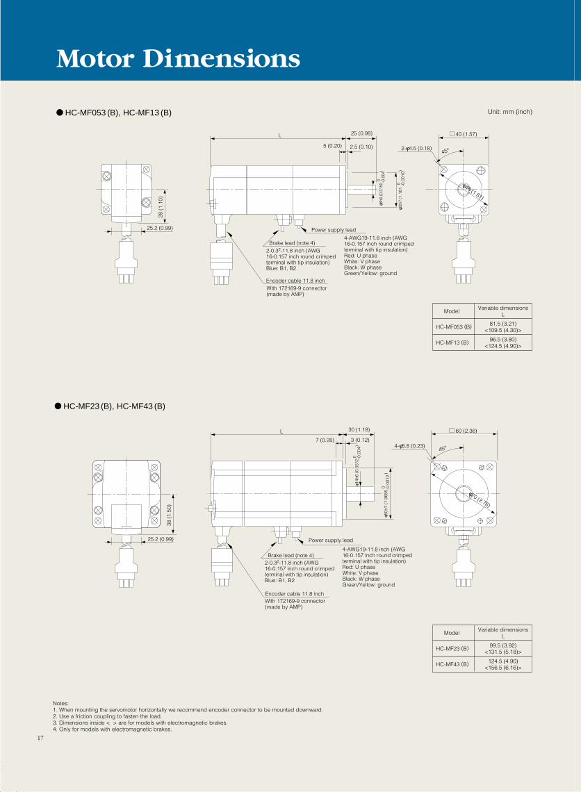
Notes:1. When mounting the servomotor horizontally we recommend encoder connector to be mounted downward.2. Use a friction coupling to fasten the load.3. Dimensions inside < > are for models with electromagnetic brakes.4. Only for models with electromagnetic brakes.
28 (
1.10
)
25.2 (0.99)
25.2 (0.99)
38 (
1.50
)
45°2-φ4.5 (0.18)
φ46 (1.81)
40 (1.57)
Power supply lead
4-AWG19-11.8 inch (AWG16-0.157 inch round crimped terminal with tip insulation)Red: U phaseWhite: V phaseBlack: W phaseGreen/Yellow: ground
Brake lead (note 4)2-0.32-11.8 inch (AWG16-0.157 inch round crimped terminal with tip insulation)Blue: B1, B2
Encoder cable 11.8 inchWith 172169-9 connector (made by AMP)
L 25 (0.98)
5 (0.20) 2.5 (0.10)
φ 30h
7 (1
.181
)
0 -0.0
010
0 -0.0
04φ 8
h6 (0
.315
0
)
Brake lead (note 4)
Power supply lead
4-AWG19-11.8 inch (AWG16-0.157 inch round crimpedterminal with tip insulation)Red: U phaseWhite: V phaseBlack: W phaseGreen/Yellow: ground
2-0.32-11.8 inch (AWG16-0.157 inch round crimped terminal with tip insulation)Blue: B1, B2
Encoder cable 11.8 inchWith 172169-9 connector (made by AMP)
L 30 (1.18)
7 (0.28) 3 (0.12)
0 -0.0
04φ 1
4h6
(0.5
512
)
0 -0.0
012
φ 50h
7 (1
.968
5
)
60 (2.36)
45°4-φ5.8 (0.23)
φ70 (2.76)
Model Variable dimensionsL
HC-MF23 (B) 99.5 (3.92)<131.5 (5.18)>
HC-MF43 (B) 124.5 (4.90)<156.5 (6.16)>
Model Variable dimensionsL
HC-MF053 (B) 81.5 (3.21)<109.5 (4.30)>
HC-MF13 (B) 96.5 (3.80)<124.5 (4.90)>
HC-MF053 (B), HC-MF13 (B)
HC-MF23 (B), HC-MF43 (B)
Motor Dimensions
17
Unit: mm (inch)
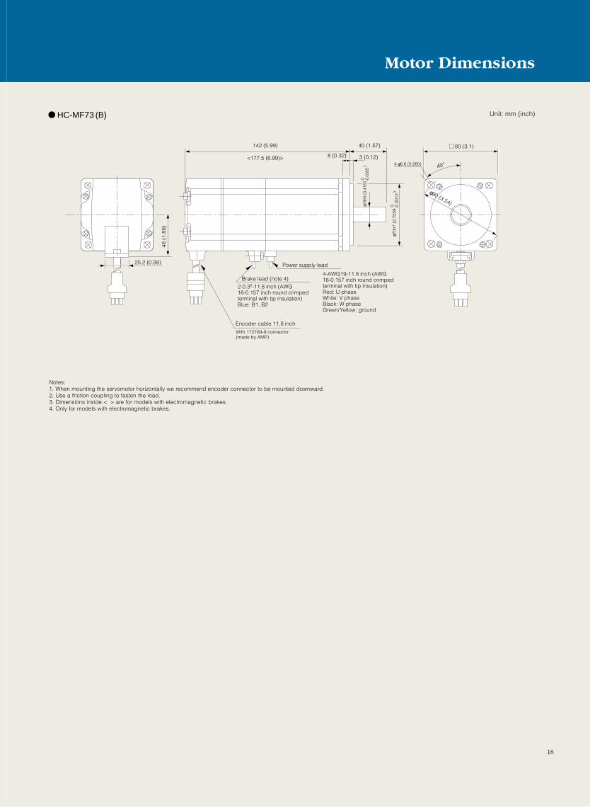
HC-MF73 (B)
48 (
1.89
)
25.2 (0.99)
142 (5.99)
<177.5 (6.99)>
40 (1.57)
8 (0.32) 3 (0.12)
Power supply lead
Brake lead (note 4)4-AWG19-11.8 inch (AWG16-0.157 inch round crimpedterminal with tip insulation)Red: U phaseWhite: V phaseBlack: W phaseGreen/Yellow: ground
2-0.32-11.8 inch (AWG16-0.157 inch round crimped terminal with tip insulation)Blue: B1, B2
Encoder cable 11.8 inchWith 172169-9 connector (made by AMP)
0 -0.0
012
φ 70h
7 (2
.755
9
)
0 -0.0
005
φ 19h
6 (0
.415
0
) 45°
80 (3.1)
4-φ6.6 (0.260)
φ90 (3.54)
Notes:1. When mounting the servomotor horizontally we recommend encoder connector to be mounted downward.2. Use a friction coupling to fasten the load.3. Dimensions inside < > are for models with electromagnetic brakes.4. Only for models with electromagnetic brakes.
18
Motor Dimensions
Unit: mm (inch)
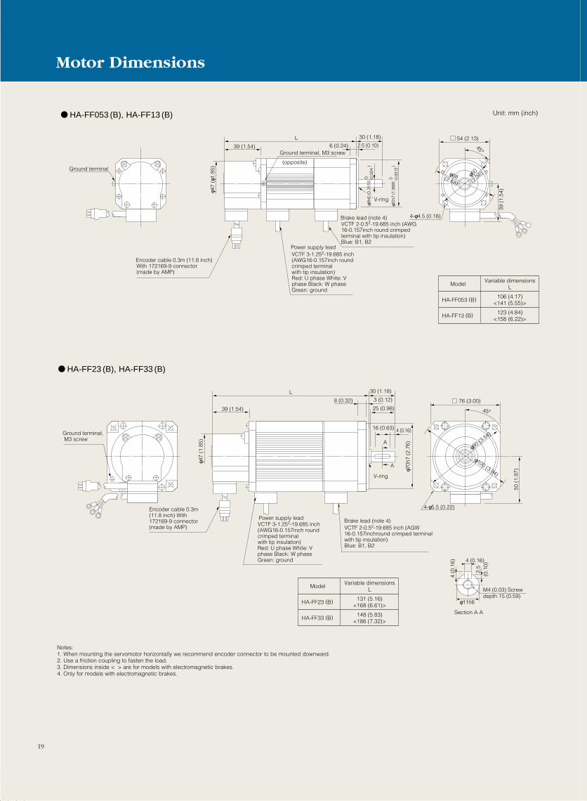
54 (2.13)45°
39 (
1.54
)
φ60
(2.36
)φ68(2.68)
4-φ4.5 (0.18)
L 30 (1.18)
39 (1.54) 2.5 (0.10)6 (0.24)
φ50h
7 (1
.968
5
)
0 -0.0
012
φ8h6
(0.
3150
)
0 -0
.004
V-ring
φ47
(φ1.
85)
L 30 (1.18)
25 (0.98)
16 (0.63) 4 (0.16)
39 (1.54)
3 (0.12)8 (0.32)φ7
0h7
(2.7
6)
φ47
(1.8
5)
A
V-ring
A
76 (3.00)
50
(1.9
7)
45°
φ90 (3
.54)
φ100 (3.94)
Power supply leadVCTF 3-1.252-19.685 inch (AWG16-0.157inch round crimped terminal with tip insulation)Red: U phase White: V phase Black: W phase Green: ground
Power supply leadVCTF 3-1.252-19.685 inch (AWG16-0.157inch round crimped terminal with tip insulation)Red: U phase White: V phase Black: W phase Green: ground
Brake lead (note 4)VCTF 2-0.52-19.685 inch (AWG16-0.157inch round crimped terminal with tip insulation)Blue: B1, B2
Brake lead (note 4)VCTF 2-0.52-19.685 inch (AGW16-0.157inchround crimped terminal with tip insulation)Blue: B1, B2
Ground terminal, M3 screw
Ground terminal
Ground terminal, M3 screw
Encoder cable 0.3m (11.8 inch)With 172169-9 connector (made by AMP)
Encoder cable 0.3m (11.8 inch) With 172169-9 connector (made by AMP)
4-φ5.5 (0.22)
(opposite)
φ11h6
4 (0
.16)
2.5
(0.1
0)
4 (0.16)
M4 (0.03) Screw depth 15 (0.59)
Section A-A
Model Variable dimensionsL
HA-FF053 (B) 106 (4.17)<141 (5.55)>
HA-FF13 (B) 123 (4.84)<158 (6.22)>
Model Variable dimensionsL
HA-FF23 (B) 131 (5.16)<168 (6.61)>
HA-FF33 (B) 148 (5.83)<186 (7.32)>
HA-FF053 (B), HA-FF13 (B)
HA-FF23 (B), HA-FF33 (B)
Notes:1. When mounting the servomotor horizontally we recommend encoder connector to be mounted downward.2. Use a friction coupling to fasten the load.3. Dimensions inside < > are for models with electromagnetic brakes.4. Only for models with electromagnetic brakes.
19
Motor Dimensions
Unit: mm (inch)
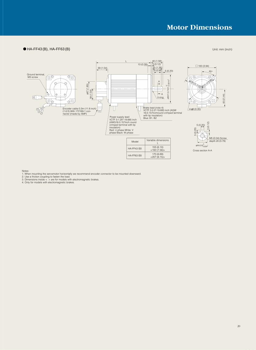
100 (3.94)
62 (
21.4
4)
45°
φ115 (4
.528)φ135 (5.315)
L 40 (1.58)
25 (0.98) 5 (0.20)39 (1.54)
3 (0.12)10 (0.39)
ø95h
7 (3
.740
1
)
0 -0.0
014
ø47
(1.8
5)39
(1.
54)
AV-ring
A
Power supply leadVCTF 3-1.252-19.685 inch (AWG16-0.157inch round crimped terminal with tip insulation)Red: U phase White: V phase Black: W phase
Ground terminal, M3 screw
Encoder cable 0.3m (11.8 inch)(1.6 ft) With 172169-1 con-nector (made by AMP)
4-φ9 (0.35)
5 (0.20)
φ16h6 (0.63 ) 0-0.0004
5 (0
.20) 3
(0.1
2)
M5 (0.04) Screwdepth 20 (0.79)
Cross section A-A
35 (1.38)
Brake lead (note 4)VCTF 2-0.52-19.685 inch (AGW16-0.157inchround crimped terminal with tip insulation)Blue: B1, B2
Model Variable dimensionsL
HA-FF43 (B) 155 (6.10)<192 (7.56)>
HA-FF63 (B) 170 (6.69)<207 (8.15)>
HA-FF43 (B), HA-FF63 (B)
Notes:1. When mounting the servomotor horizontally we recommend encoder connector to be mounted downward.2. Use a friction coupling to fasten the load.3. Dimensions inside < > are for models with electromagnetic brakes.4. Only for models with electromagnetic brakes.
20
Motor Dimensions
Unit: mm (inch)
21
GF
E HD
C
B
A
130 (5.12)
45°
41
111
(4.3
7)
81.5
(3.
21)
S30457B
MS3102A20-29PCE05-2A22-23P
Power supply connector pin assign(CE05-2A22-23P)
19.5
KL
L 55 (2.17)
50 (1.97)
3 (0.12)12 (0.47)
ø110
h7
ø165
ø145
ø24h
6
W
V
U
Encoder connector Power supply
connector
Ground
Brake (note 3)
Motor flangedirection
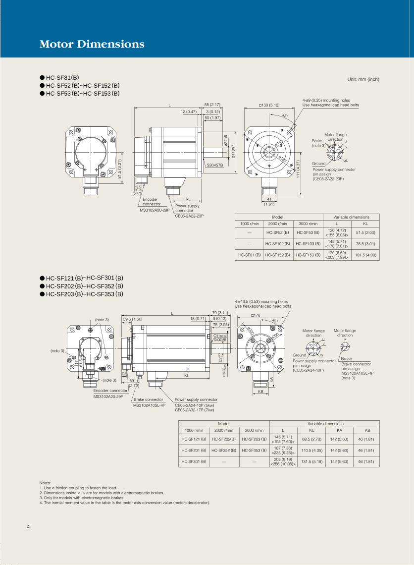
4-ø9 (0.35) mounting holesUse heaxagonal cap head bolts
(0.77)
(1.61)
Model
2000 r/min 3000 r/min L KL1000 r/min
HC-SF52 (B) HC-SF53 (B) 120 (4.72)<153 (6.03)> 51.5 (2.03)—
HC-SF102 (B) HC-SF103 (B) 145 (5.71)<178 (7.01)> 76.5 (3.01)—
HC-SF152 (B) HC-SF153 (B) 170 (6.69)<203 (7.99)> 101.5 (4.00)HC-SF81 (B)
Variable dimensions
GF
ED
C
B
AA B
117
81.5
17645°
ø114
.3 0 -0.02
5
ø35+0
.010
0
19.5
69KL
L 79 (3.11)
75 (2.95)39.5 (1.56) 18 (0.71) 3 (0.12)
S40608B
KB
KA
MS3102A20-29P
MS3102A10SL-4P
Brake connectorpin assignMS3102A10SL-4P (note 3)
CE05-2A24-10P (5kw)CE05-2A32-17P (7kw)
ø200
ø230
Power supply connectorpin assign(CE05-2A24-10P)
W
VU
Encoder connector
Power supply connector
Ground
Brake connector
4-ø13.5 (0.53) mounting holesUse heaxagonal cap head bolts
Motor flangedirection
Motor flangedirection
Brake
(note 3)
(note 3)
(note 3)
Oil seal
(2.72)
Model
2000 r/min 3000 r/min L KL1000 r/min
HC-SF202(B) HC-SF203 (B) 145 (5.71)<193 (7.60)> 68.5 (2.70)HC-SF121 (B)
HC-SF352 (B) HC-SF353 (B) 187 (7.36)<235 (9.25)> 110.5 (4.35)HC-SF201 (B)
—— 208 (8.19)<256 (10.08)>
KA
131.5 (5.18)HC-SF301 (B)
Variable dimensions
KB
142 (5.60)
142 (5.60)
142 (5.60)
46 (1.81)
46 (1.81)
46 (1.81)
HC-SF81(B) HC-SF52 (B)~HC-SF152 (B) HC-SF53 (B)~HC-SF153 (B)
HC-SF121 (B)~HC-SF301 (B) HC-SF202 (B)~HC-SF352 (B) HC-SF203 (B)~HC-SF353 (B)
Unit: mm (inch)
Notes:1. Use a friction coupling to fasten the load.2. Dimensions inside < > are for models with electromagnetic brakes.3. Only for models with electromagnetic brakes.4. The inertial moment value in the table is the motor axis conversion value (motor+decelerator).
Motor Dimensions
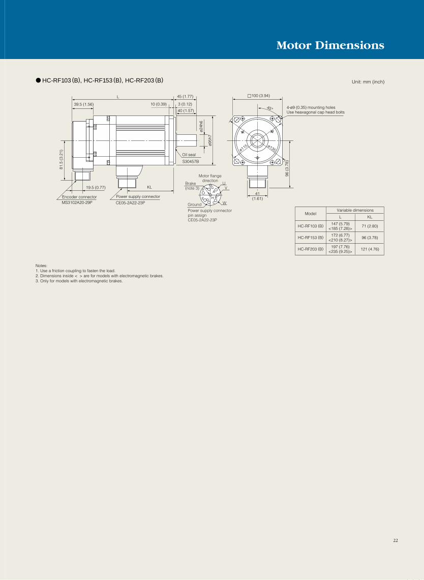
22
GF
E HD
C
B
AKL
45°
41
96 (
3.78
)
100 (3.94)
ø135ø115
CE05-2A22-23PMS3102A20-29P
19.5 (0.77)
81.5
(3.
21)
39.5 (1.56)
L 45 (1.77)
40 (1.57)
10 (0.39) 3 (0.12)
S30457B
ø95h
7
ø24h
6W
VU
Power supply connector pin assignCE05-2A22-23P
Encoder connector Power supply connector
Ground
Brake (note 3)
Motor flangedirection
4-ø9 (0.35) mounting holesUse heaxagonal cap head bolts
Oil seal
(1.61)
ModelL KL
HC-RF103 (B) 147 (5.79)<185 (7.28)> 71 (2.80)
HC-RF153 (B) 172 (6.77)<210 (8.27)> 96 (3.78)
HC-RF203 (B) 197 (7.76)<235 (9.25)> 121 (4.76)
Variable dimensions
HC-RF103 (B), HC-RF153 (B), HC-RF203 (B) Unit: mm (inch)
Notes:1. Use a friction coupling to fasten the load.2. Dimensions inside < > are for models with electromagnetic brakes.3. Only for models with electromagnetic brakes.
Motor Dimensions
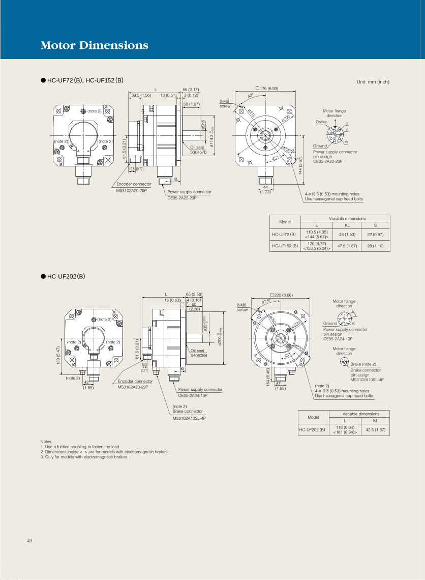
23
A
B
CDE
FG
H
U
V
W
MS3102A20-29P
CE05-2A22-23P
Oil sealS30457B
19.5 (0.77)
81.5
(3.
21)
144
(5.6
7)
L 55 (2.17)
50 (1.97)
KL
39.5 (1.56) 13 (0.51) 3 (0.12)
øSh6
ø114
.3 0 –0
.025
ø215
ø200
ø230
44(1.73)
40°
45°
2-M6screw
176 (6.93)
(note 2)
(note 2)(note 2)
Power supply connector pin assignCE05-2A22-23P
Encoder connector
Power supply connector
Ground
Brake
Motor flangedirection
4-ø13.5 (0.53) mounting holesUse heaxagonal cap head bolts
ModelL KL
HC-UF72 (B) 110.5 (4.35)<144 (5.67)> 38 (1.50)
HC-UF152 (B) 120 (4.72)<153.5 (6.04)> 47.5 (1.87)
S
22 (0.87)
28 (1.10)
Variable dimensions
A
B
C
DE
GF
A B
42
139
(5.4
7)
81.5
(3.
21)
164
(6.4
6)
19.5
L 65 (2.56)
60 (2.36)
16 (0.63) 4 (0.16)
Oil sealS40608B
ø35+
0.01
0 0
ø200
0 –0.0
46
2-M8screw
37.5°
45°
220 (8.66)
47
ø235
ø270
ø250
KL
UV
W
MS3102A20-29P
CE05-2A24-10P
Power supply connector pin assignCE05-2A24-10P
Brake connector pin assignMS3102A10SL-4PEncoder connector
Power supply connector
Ground
Brake (note 2)
Motor flangedirection
Motor flangedirection
4-ø13.5 (0.53) mounting holesUse heaxagonal cap head bolts
(note 2)
(note 2)Brake connector
MS3102A10SL-4P
(0.77)
(note 2)
(note 2)
(note 2)(note 2)
(1.65) (1.85)
ModelL KL
HC-UF202 (B) 118 (0.04)<161 (6.34)> 42.5 (1.67)
Variable dimensions
HC-UF202(B)
HC-UF72 (B), HC-UF152 (B) Unit: mm (inch)
Notes:1. Use a friction coupling to fasten the load.2. Dimensions inside < > are for models with electromagnetic brakes.3. Only for models with electromagnetic brakes.
Motor Dimensions
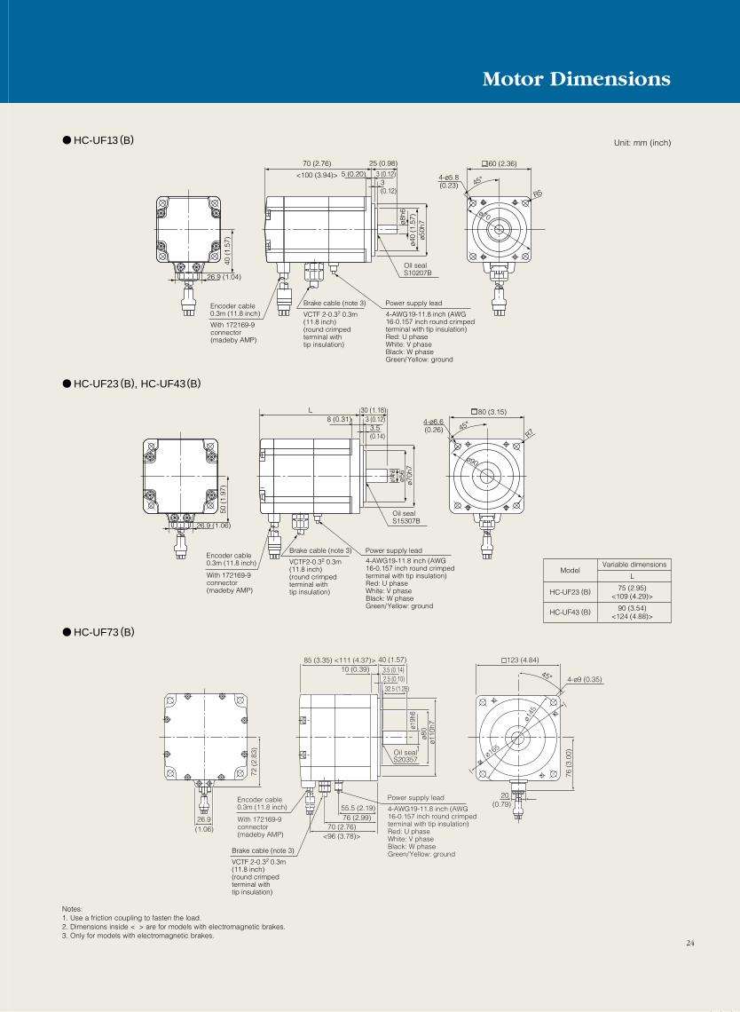
24
26.9 (1.04)
40 (
1.57
)
70 (2.76)
<100 (3.94)>
25 (0.98)
5 (0.20) 3 (0.12)3(0.12)
ø40
(1.5
7)ø5
0h7ø8
h6
4-ø5.845°
R5
ø70
60 (2.36)
Encoder cable0.3m (11.8 inch)
With 172169-9connector (madeby AMP)
Power supply leadBrake cable (note 3)
4-AWG19-11.8 inch (AWG16-0.157 inch round crimped terminal with tip insulation)Red: U phaseWhite: V phaseBlack: W phaseGreen/Yellow: ground
Oil sealS10207B
VCTF 2-0.32 0.3m (11.8 inch) (round crimped terminal with tip insulation)
(0.23)
26.9 (1.06)
50 (
1.97
)
L 30 (1.18)
3.5(0.14)
ø56
ø70h
7
ø14h
6
4-ø6.645°
R7
ø90
80 (3.15)3 (0.12)8 (0.31)
Encoder cable0.3m (11.8 inch)
With 172169-9connector (madeby AMP)
Power supply leadBrake cable (note 3)
4-AWG19-11.8 inch (AWG16-0.157 inch round crimped terminal with tip insulation)Red: U phaseWhite: V phaseBlack: W phaseGreen/Yellow: ground
Oil sealS15307B
VCTF2-0.32 0.3m (11.8 inch) (round crimped terminal with tip insulation)
(0.26)
ModelL
HC-UF23 (B) 75 (2.95)<109 (4.29)>
HC-UF43 (B) 90 (3.54)<124 (4.88)>
Variable dimensions
HC-UF13 (B)
HC-UF23 (B), HC-UF43(B)
Unit: mm (inch)
Notes:1. Use a friction coupling to fasten the load.2. Dimensions inside < > are for models with electromagnetic brakes.3. Only for models with electromagnetic brakes.
Encoder cable0.3m (11.8 inch)
With 172169-9connector (madeby AMP)
Power supply lead
Brake cable (note 3)
4-AWG19-11.8 inch (AWG16-0.157 inch round crimped terminal with tip insulation)Red: U phaseWhite: V phaseBlack: W phaseGreen/Yellow: ground
VCTF 2-0.32 0.3m (11.8 inch) (round crimped terminal with tip insulation)
26.9
72 (
2.83
)
20
ø165
ø145
76 (
3.00
)
123 (4.84)
45° 4-ø9 (0.35)
85 (3.35) <111 (4.37)>10 (0.39)
40 (1.57)3.5 (0.14)2.5 (0.10)32.5 (1.28)
Oil sealS20357
ø19h
6
ø80
ø110
h7
55.5 (2.19)76 (2.99)
70 (2.76)<96 (3.78)>
(1.06)
(0.79)
HC-UF73 (B)
Motor Dimensions
25
Special Specifications
A
A
Q
R
QK QL U
Y
W øS
r
R
Q
A W
T U
A
QK QL
R R
Q
Q
27 (1.06)
YøS
3.5 (0.14)2.5 (0.10)
HC-UF23, 43 HC-UF73
Section A-A
30 (1.18)
25.5 (1.00)
ø8h6
1
R
QK
ø8h6
1
Section A-A
Key way
HC-SF, RF, UF2000r/min series
Variable dimension table
D-cut (50, 100W)
HA-FF series D-cut (50, 100W)
With key (200, 400, 750W)
HC-MF, UF3000r/min series
Variable dimension table
Variable dimension table
Motorseries
Capacity(kW)
Variable dimensions
R
55 (2.17)
79 (3.11)
45 (1.77)
55 (2.17)
55 (2.17)
65 (2.56)
Q
50 (1.97)
75 (2.95)
40 (1.57)
50 (1.97)
50 (1.97)
60 (2.36)
QK
36 (1.42)
55 (2.17)
25 (0.98)
42 (1.65)
45 (1.77)
55 (2.17)
r
4 (0.16)
5 (0.20)
4 (0.16)
3 (0.12)
4 (0.16)
5 (0.20)
YQL
5 (0.20)
5 (0.20)
5 (0.20)
3 (0.12)
5 (0.20)
5 (0.20)
WS
0.5~1.5
2~3.5
1, 1.5, 2
0.75
1.5
2
HC-RF
HC-UF
HC-SF(note 3)
24h6
35
24h6
22h6
28h6
35h6
+0.010
0-0.036 0-0.036 0-0.030 0-0.036 0-0.030
0-0.0368 (0.31)
10 (0.39)
8 (0.31)
6 (0.24)
8 (0.31)
10 (0.39)
U
+0.20
+0.20
+0.20
+0.20
+0.20
+0.204 (0.16)
5 (0.20)
4 (0.16)
3.5 (0.14)
4 (0.16)
5 (0.20)
M8 (0.056) screwsDepth: 20mm
(0.79 inch)
Motorseries
Capacity(kW)
Variable dimensions
S
14h6
19h6
14h6
19h6
T
5(0.20)
6(0.24)
5(0.20)
6(0.24)
R
30(1.18)
40(1.57)
30(1.18)
40(1.57)
W
5(0.20)
6(0.24)
5(0.20)
6(0.24)
Q
27(1.06)
37(1.46)
23.5(0.93)
32.5(1.28)
U
3(0.12)
3.5(0.14)
3(0.12)
3.5(0.14)
QL
3(0.12)
5(0.20)
3(0.12)
5(0.20)
Y
M4 (0.028) screwsDepth: 15mm (0.59 inch)
M5 (0.035) screwsDepth: 20mm (0.79 inch)
M4 (0.028) screwsDepth: 15mm (0.59 inch)
M5 (0.035) screwsDepth: 20mm (0.79 inch)
QK
20(0.79)
25(0.98)
20(0.79)
25(0.98)
200, 400
750
200, 400
750HC-UF
HC-MF
Motorseries
Capacity(kW)
Variable dimensions
R
25 (0.98)
25 (0.98)
Q
20.5 (0.81)
17.5 (0.69)
50, 100
100
HC-MF
HC-UF
(0.31)
(0.31)
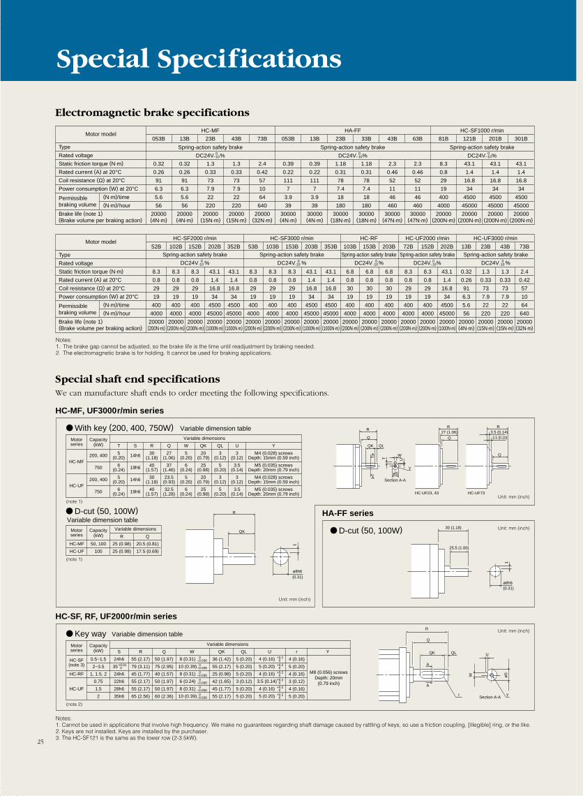
Special shaft end specificationsWe can manufacture shaft ends to order meeting the following specifications.
Electromagnetic brake specifications
Type
Rated voltage
Static friction torque (N·m)
Rated current (A) at 20°CCoil resistance (Ω) at 20°CPower consumption (W) at 20°C
(N·m)/time(N·m)/hour
Brake life (note 1)(Brake volume per braking action)
Permissiblebraking volume
52B
8.3
0.8
29
19
400
4000
20000(200N·m)
102B
8.3
0.8
29
19
400
4000
20000(200N·m)
152B
8.3
0.8
29
19
400
4000
20000(200N·m)
202B
43.1
1.4
16.8
34
4500
45000
20000(1000N·m)
352B
43.1
1.4
16.8
34
4500
45000
20000(1000N·m)
53B
8.3
0.8
29
19
400
4000
20000(200N·m)
103B
8.3
0.8
29
19
400
4000
20000(200N·m)
153B
8.3
0.8
29
19
400
4000
20000(200N·m)
203B
43.1
1.4
16.8
34
4500
45000
20000(1000N·m)
353B
43.1
1.4
16.8
34
4500
45000
20000(1000N·m)
103B
6.8
0.8
30
19
400
4000
20000(200N·m)
153B
6.8
0.8
30
19
400
4000
20000(200N·m)
203B
6.8
0.8
30
19
400
4000
20000(200N·m)
72B
8.3
0.8
29
19
400
4000
20000(200N·m)
152B
8.3
0.8
29
19
400
4000
20000(200N·m)
202B
43.1
1.4
16.8
34
4500
45000
20000(1000N·m)
13B
0.32
0.26
91
6.3
5.6
56
20000(4N·m)
23B
1.3
0.33
73
7.9
22
220
20000(15N·m)
43B
1.3
0.33
73
7.9
22
220
20000(15N·m)
73B
2.4
0.42
57
10
64
640
20000(32N·m)
Spring-action safety brake
DC24V %
Spring-action safety brake
DC24V %
Spring-action safety brake
DC24V %
Spring-action safety brake
DC24V %
Spring-action safety brake
DC24V %
HC-SF2000 r/min HC-SF3000 r/min HC-RF HC-UF2000 r/min HC-UF3000 r/minMotor model
Type
Rated voltage
Static friction torque (N·m)
Rated current (A) at 20°CCoil resistance (Ω) at 20°CPower consumption (W) at 20°C
(N·m)/time(N·m)/hour
Brake life (note 1)(Brake volume per braking action)
Permissiblebraking volume
053B
0.32
0.26
91
6.3
5.6
56
20000(4N·m)
13B
0.32
0.26
91
6.3
5.6
56
20000(4N·m)
23B
1.3
0.33
73
7.9
22
220
20000(15N·m)
43B
1.3
0.33
73
7.9
22
220
20000(15N·m)
73B
2.4
0.42
57
10
64
640
20000(32N·m)
053B
0.39
0.22
111
7
3.9
39
30000(4N·m)
13B
0.39
0.22
111
7
3.9
39
30000(4N·m)
23B
1.18
0.31
78
7.4
18
180
30000(18N·m)
33B
1.18
0.31
78
7.4
18
180
30000(18N·m)
43B
2.3
0.46
52
11
46
460
30000(47N·m)
63B
2.3
0.46
52
11
46
460
30000(47N·m)
81B
8.3
0.8
29
19
400
4000
20000(200N·m)
121B
43.1
1.4
16.8
34
4500
45000
20000(200N·m)
201B
43.1
1.4
16.8
34
4500
45000
20000(200N·m)
301B
43.1
1.4
16.8
34
4500
45000
20000(200N·m)
Motor modelHC-MF
Spring-action safety brake
DC24V %
Spring-action safety brake
DC24V %
HA-FF HC-SF1000 r/min
Spring-action safety brake
DC24V % 0-10
0-10
0-10
Notes:1. Cannot be used in applications that involve high frequency. We make no guarantees regarding shaft damage caused by rattling of keys, so use a friction coupling, [illegible] ring, or the like.2. Keys are not installed. Keys are installed by the purchaser.3. The HC-SF121 is the same as the lower row (2-3.5kW).
Notes:1. The brake gap cannot be adjusted, so the brake life is the time until readjustment by braking needed.2. The electromagnetic brake is for holding. It cannot be used for braking applications.
(note 1)
(note 1)
(note 2)
Unit: mm (inch)
Unit: mm (inch)
Unit: mm (inch)
Unit: mm (inch)
0-10
0-10
0-10
0-10
0-10

SERVOAMPLIFIERS
MELSERVOJ2-A
Global Applications forSuperb Operation
in the Toughest Environments• Satisfies global industrial standards
• Separate wiring of the control power supply•Real-time auto-tuning, and high responsiveness
• Torque control function• Servo lock anti-vibration function
• Personal computer interface as standard •Automatic motor recognition
26
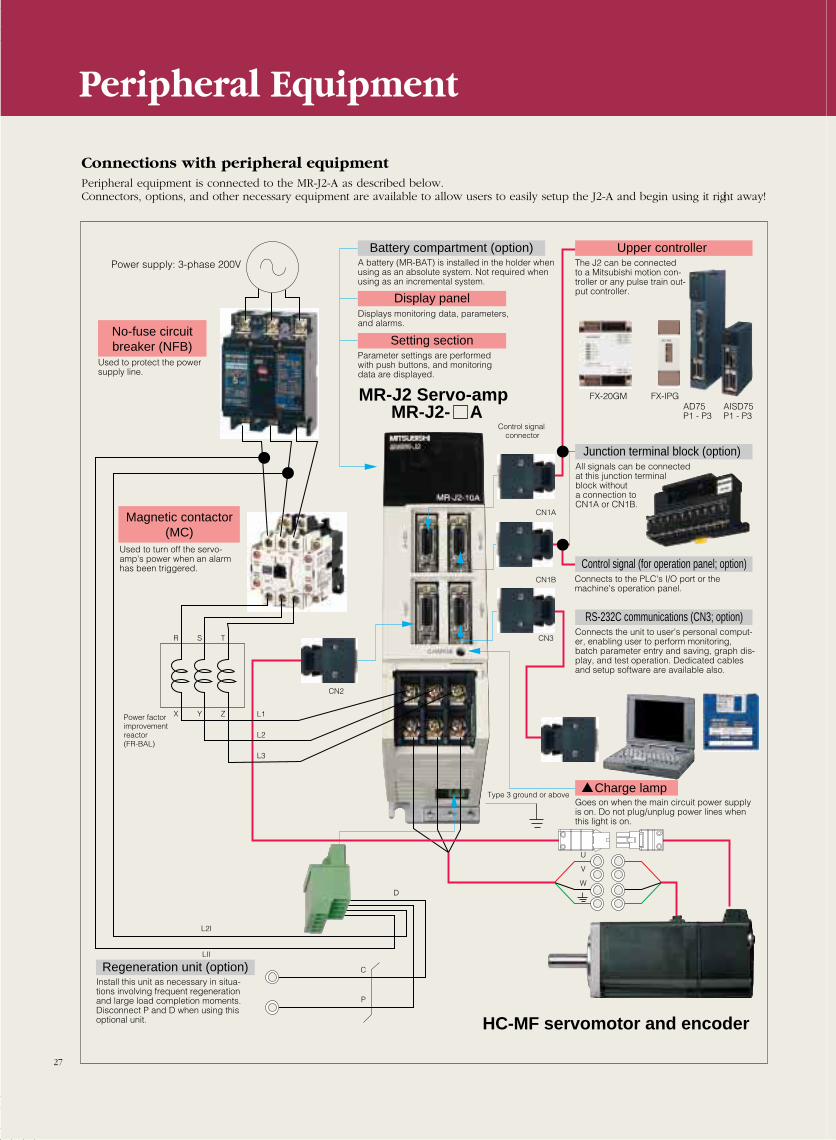
Connections with peripheral equipmentPeripheral equipment is connected to the MR-J2-A as described below.Connectors, options, and other necessary equipment are available to allow users to easily setup the J2-A and begin using it right away!
Peripheral Equipment
Used to protect the power supply line.
No-fuse circuit breaker (NFB)
Used to turn off the servo-amp's power when an alarm has been triggered.
Magnetic contactor (MC)
Power supply: 3-phase 200V
Battery compartment (option) Upper controller
Display panel
Setting section
A battery (MR-BAT) is installed in the holder when using as an absolute system. Not required when using as an incremental system.
The J2 can be connected to a Mitsubishi motion con-troller or any pulse train out-put controller.
Junction terminal block (option)All signals can be connected at this junction terminal block without a connection to CN1A or CN1B.
Regeneration unit (option)Install this unit as necessary in situa-tions involving frequent regeneration and large load completion moments. Disconnect P and D when using thisoptional unit.
Control signal (for operation panel; option)Connects to the PLC's I/O port or the machine's operation panel.
RS-232C communications (CN3; option)Connects the unit to user's personal comput-er, enabling user to perform monitoring, batch parameter entry and saving, graph dis-play, and test operation. Dedicated cables and setup software are available also.
Charge lampGoes on when the main circuit power supply is on. Do not plug/unplug power lines when this light is on.
Displays monitoring data, parameters, and alarms.
Parameter settings are performed with push buttons, and monitoring data are displayed.
Type 3 ground or above
Control signal connector
HC-MF servomotor and encoder
MR-J2 Servo-ampMR-J2- A
CN2
CN1A
CN1B
CN3
C
P
D
L2I
L1
L2
L3
LII
U
V
W
FX-20GM FX-IPGAD75P1 - P3
AISD75P1 - P3
R S T
X Y ZPower factorimprovement reactor(FR-BAL)
27
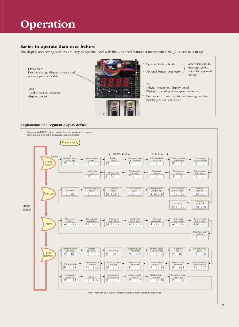
Easier to operate than ever beforeThe display and setting sections are easy to operate. And with the advanced features it incorporates, the J2 is easy to start up.
Explanation of 7-segment display device
C r E P n F U
d C L S C y b J L
r - o F d o o n T S T I T S T 2 T S T 3 - A
H I 0 = 0 0
0
0
A - - A I - - A 2 - - A 3 - - A 4 - - A 5 - - A 6 - -
P 0 0
P
P 0 I P 0 2 P 0 3 P 0 4 P 0 5 P 0 6
I 3 P I 2 P I I P I 0 P 0 9 P 0 8 P 0 7
PP
E - -
DOWN button UP button
I 4 P I 5 P I 6 P I 7 P I 8 P I 9
Pressing the MODE button causes the display mode to change one step at a time in the sequence illustrated below.
Power supply
MODE button
Status display
Diagnostic
Alarm
Basic parameter
Feedback pulse accumulation
Motor rotation speed
Load/inertia ratio
Sequence
Most recent alarm
Control mode/regeneration option selection
Function selection 1 Auto-tuning
Electronic gear : Numerator
Electronic gear : Denominator
In-position range
Position control gain 1
Position acceleration/decel-eration time (smoothing)
Internal speed command 1
Internal speed command 2
Internal speed command 3
Speed accelera-tion time
Speed decelera-tion timeS time constant
Torque com-mand time Spare
Communications baud rate selection/alarm history clear
Analog monitor output
Status display selection
Parameter entry prohibition
Second most recent alarm
Third most recent alarm
Fourth most recent alarm
Fifth most recent alarm
Sixth most recent alarm
Seventh most recent alarm
Parameter error number
External signal display
DO forced output
Test operation (JOG)
Test operation (positioning)
Test operation (without motor)
Software version L
Software version HVC offset
ABS counterPosition within one rotation
Peak load factor
Effective load factor
Regeneration load factor
Standingpulse
Command pulse accumulation
Command pulse frequency
Speed command voltage or speed limit voltage
Torque limit voltage or torque command voltage
Note: Press the SET button to display actual data in status display mode
(note)
Operation
UP/DOWN:Used to change display content andre-enter parameter data
MODE:Used to switch betweendisplay modes
Optional battery holder
Optional battery connector
SET:4-digit, 7-segement display panelDisplays operating status, parameters, etc.
Used to set parameters, for auto-tuning, and forswitching to the test screen
When using in anabsolute system,install the optionalbattery.
28
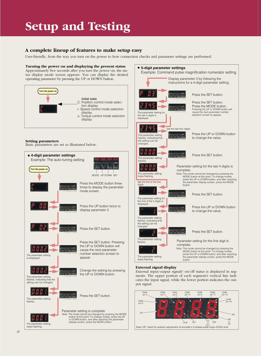
Setting parametersBasic parameters are set as illustrated below.
External signal displayExternal input/output signals' on/off status is displayed in seg-ments. The upper portion of each segment's vertical line indi-cates the input signal, while the lower portion indicates the out-put signal.
Setup and Testing
A complete lineup of features to make setup easyUser-friendly, from the way you turn on the power to how connection checks and parameter settings are performed.
Turning the power on and displaying the present statusApproximately five seconds after you turn the power on, the sta-tus display mode screen appears. You can display the desiredoperating parameter by pressing the UP or DOWN button.
Turn the power on
Turn the power on
Initial stateC: Position control mode selec-
tion displayr: Speed control mode selection
displayu: Torque control mode selection
display
4-digit parameter settingsExample: The auto-tuning setting
5-digit parameter settings Example: Command pulse magnification numerator setting
Press the MODE button three times to display the parameter mode screen.
Display parameter 3 by following the instructions for a 4-digit parameter setting.
Press the UP button twice to display parameter 2.
Press the SET button.
Press the SET button.
The parameter setting for the last 4 digits is displayed.
The parameter setting flashes, indicating that the setting can be changed.
The parameter setting flashes.
Note: The mode cannot be changed by pressing the MODE button at this point. To change modes, press the UP or DOWN button, and after reaching the parameter display screen, press the MODE button.
The parameter setting stops flashing.
Set the first of the five digits.
The parameter setting for the first of the 5 digits is displayed.
The parameter setting flashes, indicating that the setting can be changed.
The parameter setting flashes.
The parameter setting stops flashing.
Press the UP or DOWN button to change the value.
Press the SET button.
Parameter setting for the last 4 digits is complete.
Note: The mode cannot be changed by pressing the MODE button at this point. To change modes, press the UP or DOWN button, and after reaching the parameter display screen, press the MODE button.
Parameter setting for the first digit is complete.
Press the SET button.
Press the UP or DOWN button to change the value.
Press the SET button.
Press the SET button.Press the MODE button. Pressing the UP or DOWN button will cause the next parameter number selection screen to appear.
The parameter settingis displayed.
The parameter settingflashes, indicating that the setting can be changed.
The parameter settingflashes.
The parameter setting stops flashing.
Press the SET button. Pressing the UP or DOWN button will cause the next parameter number selection screen to appear.
Change the setting by pressing the UP or DOWN button.
Press the SET button.
Note: The mode cannot be changed by pressing the MODE button at this point. To change modes, press the UP or DOWN button, and after reaching the parameter display screen, press the MODE button.
Parameter setting is complete.
Set the last four digits.
Note: OP: Used for position adjustment of encoder's Z-phase pulse origin DOGU end
CNIB pin 3
CNIB pin 7
CNIA pin 3
CNIB pin 14
CNIB pin 5
CNIB pin 17
CNIB pin 15
CNIB pin 9
OP
CNIB pin 16
TLC or VLC
INP or SA
RD
ZSPD01ALM
MODE DOWN SETUP
29
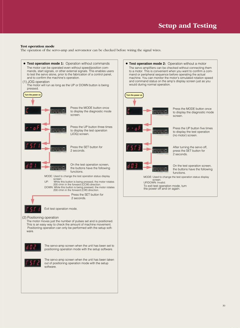
Test operation modeThe operation of the servo-amp and servomotor can be checked before wiring the signal wires.
Test operation mode 1: Operation without commandsThe motor can be operated even without speed/position com-mands, start signals, or other external signals. This enables users to test the servo alone, prior to the fabrication of a control panel, and to confirm the machine's operation.
The motor will run as long as the UP or DOWN button is being pressed.
Test operation mode 2: Operation without a motorThe servo amplifiers can be checked without connecting them to a motor. This is convenient when you want to confirm a com-mand or peripheral sequence before operating the actual machine. You can monitor the motor's simulated rotation speed and command status on the amp's display screen just as you would during normal operation.
The motor moves just the number of pulses set and is positioned. This is an easy way to check the amount of machine movement. Positioning operation can only be performed with the setup soft-ware.
(1) JOG operation
(2) Positioning operation
Press the MODE button once to display the diagnostic mode screen.
Press the UP button three times to display the test operation (JOG) screen.
Press the SET button for 2 seconds.
On the test operation screen, the buttons have the following functions.
Press the MODE button onceto display the diagnostic mode screen.
Press the UP button five times to display the test operation (no motor) screen.
After turning the servo off, press the SET button for 2 seconds.
On the test operation screen, the buttons have the following functions.
Press the SET button for 2 seconds.
MODE: Used to change the test operation status display screen.
UP: While this button is being pressed, the motor rotates 200 r/min in the forward (CCW) direction.
DOWN: While this button is being pressed, the motor rotates 200 r/min in the forward (CW) direction.
MODE: Used to change the test operation status display screen.
UP/DOWN: Invalid.To exit test operation mode, turn the power off and on again.
Exit test operation mode.
The servo-amp screen when the unit has been set to positioning operation mode with the setup software.
The servo-amp screen when the unit has been taken out of positioning operation mode with the setup software.
Turn the power on Turn the power on
30
Setup and Testing
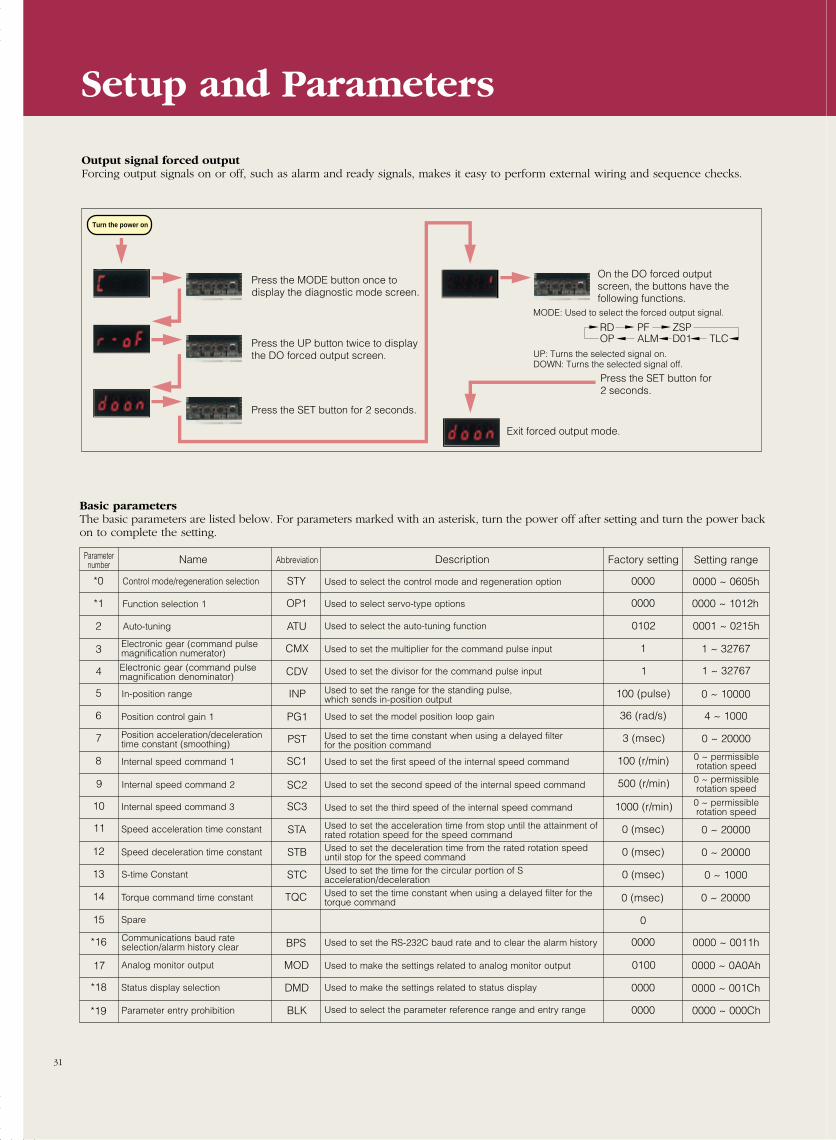
*0
*1
2
3
4
5
6
7
8
9
10
11
12
13
14
15
*16
17
*18
*19
Name Abbreviation Description Factory setting Setting range
Control mode/regeneration selection
Function selection 1
Auto-tuning
Electronic gear (command pulsemagnification numerator)
Electronic gear (command pulsemagnification denominator)
In-position range
Position control gain 1
Position acceleration/decelerationtime constant (smoothing)
Internal speed command 1
Internal speed command 2
Internal speed command 3
Speed acceleration time constant
Speed deceleration time constant
S-time Constant
Torque command time constant
Spare
Communications baud rateselection/alarm history clear
Analog monitor output
Status display selection
Parameter entry prohibition
Used to select the control mode and regeneration option
Used to select servo-type options
Used to select the auto-tuning function
Used to set the multiplier for the command pulse input
Used to set the divisor for the command pulse input
Used to set the range for the standing pulse, which sends in-position output
Used to set the model position loop gain
Used to set the time constant when using a delayed filter for the position command
Used to set the first speed of the internal speed command
Used to set the second speed of the internal speed command
Used to set the third speed of the internal speed command
Used to set the acceleration time from stop until the attainment of rated rotation speed for the speed commandUsed to set the deceleration time from the rated rotation speeduntil stop for the speed commandUsed to set the time for the circular portion of Sacceleration/deceleration Used to set the time constant when using a delayed filter for thetorque command
Used to set the RS-232C baud rate and to clear the alarm history
Used to make the settings related to analog monitor output
Used to make the settings related to status display
Used to select the parameter reference range and entry range
Parameternumber
STY
OP1
ATU
CMX
CDV
INP
PG1
PST
SC1
SC2
SC3
STA
STB
STC
TQC
BPS
MOD
DMD
BLK
0000
0000
0102
1
1
100 (pulse)
36 (rad/s)
3 (msec)
100 (r/min)
500 (r/min)
1000 (r/min)
0 (msec)
0 (msec)
0 (msec)
0 (msec)
0
0000
0100
0000
0000
0000 ~ 0605h
0000 ~ 1012h
0001 ~ 0215h
1 ~ 32767
1 ~ 32767
0 ~ 10000
4 ~ 1000
0 ~ 20000
0 ~ permissible rotation speed
0 ~ permissible rotation speed
0 ~ permissible rotation speed
0 ~ 20000
0 ~ 20000
0 ~ 1000
0 ~ 20000
0000 ~ 0011h
0000 ~ 0A0Ah
0000 ~ 001Ch
0000 ~ 000Ch
Setup and Parameters
Output signal forced outputForcing output signals on or off, such as alarm and ready signals, makes it easy to perform external wiring and sequence checks.
Basic parametersThe basic parameters are listed below. For parameters marked with an asterisk, turn the power off after setting and turn the power backon to complete the setting.
Press the MODE button once to display the diagnostic mode screen.
On the DO forced output screen, the buttons have the following functions.
Press the SET button for 2 seconds.
Exit forced output mode.
Press the UP button twice to display the DO forced output screen.
Press the SET button for 2 seconds.
MODE: Used to select the forced output signal.
UP: Turns the selected signal on.DOWN: Turns the selected signal off.
RD PF ZSPOP ALM D01 TLC
Turn the power on
31
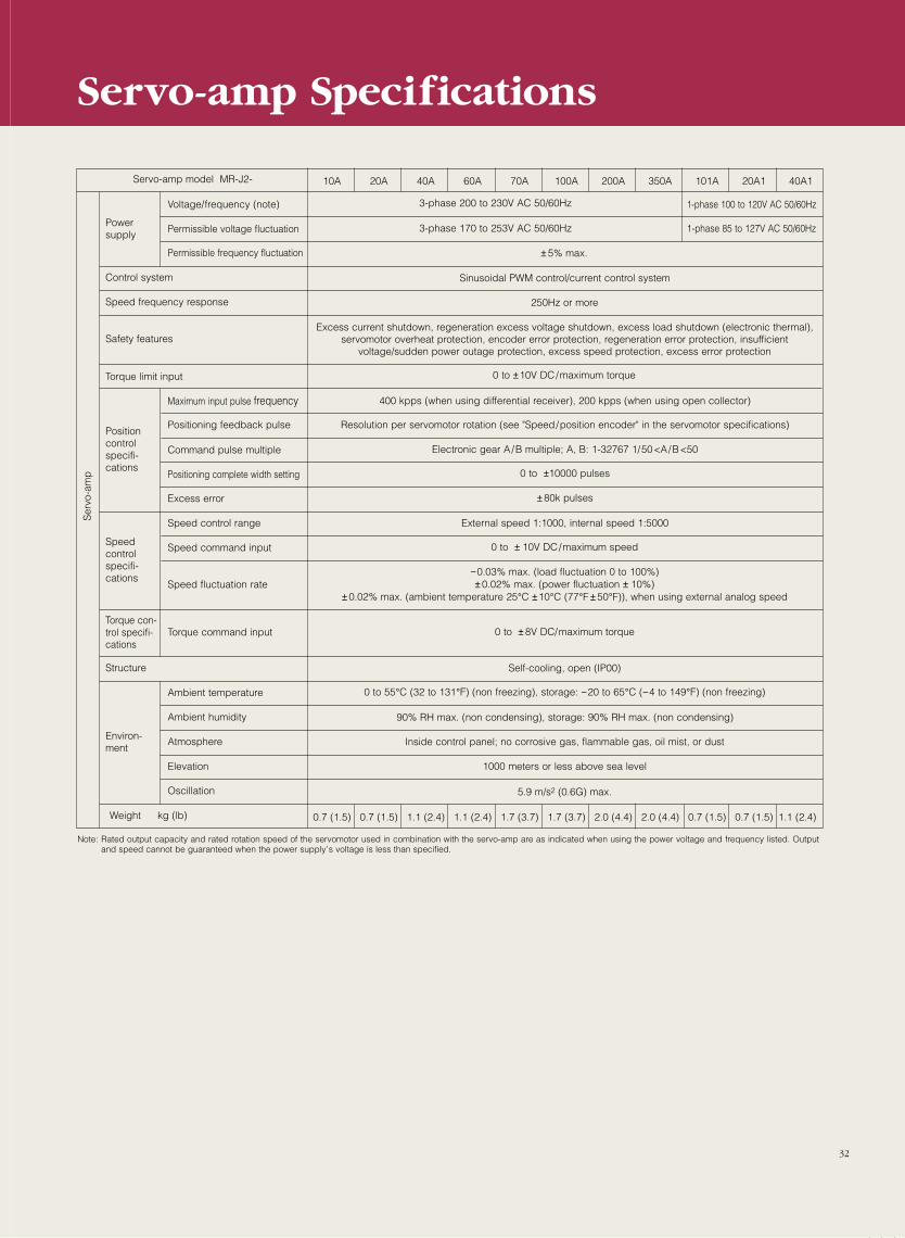
Servo-amp model MR-J2-
Power supply
Voltage/frequency (note)
Permissible voltage fluctuation
Permissible frequency fluctuation
3-phase 200 to 230V AC 50/60Hz
3-phase 170 to 253V AC 50/60Hz
± 5% max.
Control system
Speed frequency response
Safety features
Torque limit input
Sinusoidal PWM control/current control system
250Hz or more
Excess current shutdown, regeneration excess voltage shutdown, excess load shutdown (electronic thermal),servomotor overheat protection, encoder error protection, regeneration error protection, insufficient
voltage/sudden power outage protection, excess speed protection, excess error protection
400 kpps (when using differential receiver), 200 kpps (when using open collector)
Ser
vo-a
mp
Positioncontrolspecifi-cations
Maximum input pulse frequency
Positioning feedback pulse
Command pulse multiple
Positioning complete width setting
Excess error
Resolution per servomotor rotation (see "Speed/position encoder" in the servomotor specifications)
Electronic gear A/B multiple; A, B: 1-32767 1/50<A/B<50
0 to ±10000 pulses
± 80k pulses
External speed 1:1000, internal speed 1:5000
0 to ±10V DC/maximum torque
Speedcontrolspecifi-cations
Speed control range
Speed command input
Speed fluctuation rate
0 to ± 10V DC/maximum speed
−0.03% max. (load fluctuation 0 to 100%)± 0.02% max. (power fluctuation ± 10%)
± 0.02% max. (ambient temperature 25°C ±10°C (77°F ± 50°F)), when using external analog speed
0 to ± 8V DC/maximum torque
Self-cooling, open (IP00)
0 to 55°C (32 to 131°F) (non freezing), storage: −20 to 65°C (−4 to 149°F) (non freezing)
90% RH max. (non condensing), storage: 90% RH max. (non condensing)
Inside control panel; no corrosive gas, flammable gas, oil mist, or dust
1000 meters or less above sea level
5.9 m/s2 (0.6G) max.
Structure
Ambient temperature
Ambient humidity
Atmosphere
Elevation
Oscillation
Weight kg (lb)
Torque con-trol specifi-cations
Torque command input
Environ-ment
Note: Rated output capacity and rated rotation speed of the servomotor used in combination with the servo-amp are as indicated when using the power voltage and frequency listed. Outputand speed cannot be guaranteed when the power supply’s voltage is less than specified.
Servo-amp Specifications
10A 20A 40A 60A 70A 100A 200A 350A 101A 20A1 40A1
0.7 (1.5) 0.7 (1.5) 1.1 (2.4) 1.1 (2.4) 1.7 (3.7) 1.7 (3.7) 2.0 (4.4) 2.0 (4.4) 0.7 (1.5) 0.7 (1.5) 1.1 (2.4)
1-phase 100 to 120V AC 50/60Hz
1-phase 85 to 127V AC 50/60Hz
32
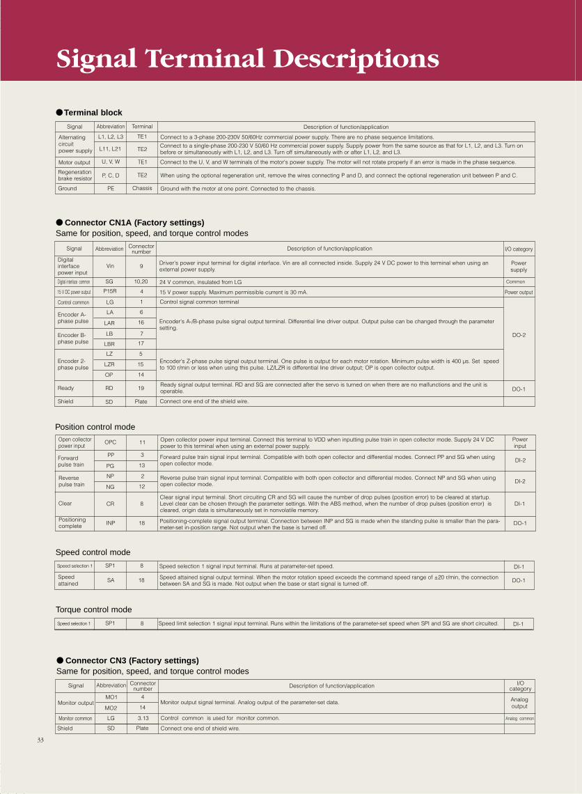
AbbreviationSignal Description of function/application
Digital interfacepower input
Driver's power input terminal for digital interface. Vin are all connected inside. Supply 24 V DC power to this terminal when using anexternal power supply.
Vin 9
Abbreviation Terminal Signal Description of function/application
Alternating circuitpower supply
Connect to a 3-phase 200-230V 50/60Hz commercial power supply. There are no phase sequence limitations.
Connect to a single-phase 200-230 V 50/60 Hz commercial power supply. Supply power from the same source as that for L1, L2, and L3. Turn onbefore or simultaneously with L1, L2, and L3. Turn off simultaneously with or after L1, L2, and L3.
Motor output Connect to the U, V, and W terminals of the motor's power supply. The motor will not rotate properly if an error is made in the phase sequence.
Regenerationbrake resistor When using the optional regeneration unit, remove the wires connecting P and D, and connect the optional regeneration unit between P and C.
Ground with the motor at one point. Connected to the chassis.Ground
L1, L2, L3
L11, L21
U, V, W
P, C, D
PE
TE1
TE2
TE1
TE2
Chassis
Connector number
15 V DC power output 15 V power supply. Maximum permissible current is 30 mA.
Control common Control signal common terminal
Encoder's A-/B-phase pulse signal output terminal. Differential line driver output. Output pulse can be changed through the parametersetting.
Encoder A-phase pulse
P15R
LG
LA
4
1
6
Digital interface common 24 V common, insulated from LG
Encoder B-phase pulse
I/O category
Power supply
Common
Power output
Encoder's Z-phase pulse signal output terminal. One pulse is output for each motor rotation. Minimum pulse width is 400 µs. Set speedto 100 r/min or less when using this pulse. LZ/LZR is differential line driver output; OP is open collector output.
Encoder 2-phase pulse
LAR 16
LB 7
LBR 17
LZ 5
LZR 15
OP 14
Ready 19
SD PlateShield
RDReady signal output terminal. RD and SG are connected after the servo is turned on when there are no malfunctions and the unit isoperable.
Connect one end of the shield wire.
Connector CN1A (Factory settings)Same for position, speed, and torque control modes
SG 10,20
DO-2
DO-1
Open collectorpower input
Open collector power input terminal. Connect this terminal to VDD when inputting pulse train in open collector mode. Supply 24 V DCpower to this terminal when using an external power supply.
Forward pulse train signal input terminal. Compatible with both open collector and differential modes. Connect PP and SG when usingopen collector mode.
Forwardpulse train
OPC
PP
11
3
Reversepulse train
Clear signal input terminal. Short circuiting CR and SG will cause the number of drop pulses (position error) to be cleared at startup.Level clear can be chosen through the parameter settings. With the ABS method, when the number of drop pulses (position error) iscleared, origin data is simultaneously set in nonvolatile memory.
Clear
PG 13
NP 2
NG 12
Positioning complete 18INP Positioning-complete signal output terminal. Connection between INP and SG is made when the standing pulse is smaller than the para-
meter-set in-position range. Not output when the base is turned off.
DI-2
DO-1
Position control mode
Reverse pulse train signal input terminal. Compatible with both open collector and differential modes. Connect NP and SG when usingopen collector mode.
Powerinput
DI-2
CR 8 DI-1
Speed selection 1 Speed selection 1 signal input terminal. Runs at parameter-set speed.SP1 8 DI-1
Speed control mode
Speed attained
Speed attained signal output terminal. When the motor rotation speed exceeds the command speed range of ±20 r/min, the connectionbetween SA and SG is made. Not output when the base or start signal is turned off.
SA 18
Speed selection 1 Speed limit selection 1 signal input terminal. Runs within the limitations of the parameter-set speed when SPI and SG are short circuited.SP1 8 DI-1
Torque control mode
Monitor output signal terminal. Analog output of the parameter-set data.Monitor outputMO1 4
Monitor common
Signal
MO2 14
LG 3.13
SD Plate
I/Ocategory
Connector CN3 (Factory settings)Same for position, speed, and torque control modes
Control common is used for monitor common.
Analog output
Abbreviation Connectornumber Description of function/application
Shield Connect one end of shield wire.
Analog common
Terminal block
Signal Terminal Descriptions
DO-1
33
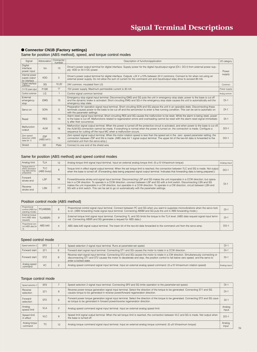
Abbreviation Connectornumber
Signal Description of function/application
Digital interfacepower input
Driver's power output terminal for digital interface. Supply power for the digital input/output signal (DI-I, DO-I) from external power sup-ply: VDD or 24 V DC power.
15 V DC power output
24V common, insulated from LG
Shield
15V power supply. Maximum permissible current is 30 mA.
Emergency stop signal input terminal. Disconnecting EMG and SG puts the unit in emergency stop state; power to the base is cut offand the dynamic brake is activated. Short circuiting EMG and SG in the emergency stop state causes the unit to automatically exit theemergency stop state.
ZSP(ABS bit1)
Vin
SG
Control common
P15R
13
10,20
1
11
Digital interfacecommon
Driver's power output terminal for digital interface. Outputs +24 V ±10% between 24 V commons. Connect to Vin when not using anexternal power supply. Do not allow the sum of current for the command unit and input/output relay drive to exceed 80 mA.
Externalemergencystop
I/O category
Power supply
Analog common
Preparation for operation signal input terminal. Short circuiting SON and SG places the unit in an operable state. Disconnecting theseterminals causes power to the base to be cut off and the servomotor to enter a free running condition. This can be set to automatic onwith the parameter settings.
19
VDD 3
EMG
LG
Malfunctionoutput
15
Servo on SON 5
Connect to one end of the shield wire.PlateSD
Zero speeddetection (ABSdata bit 1)
14
ALM 18
Reset RESAlarm reset signal input terminal. Short circuiting RES and SG causes the malfunction to be reset. While the alarm is being reset, powerto the base is cut off. Malfunctions related to regeneration errors and overloading cannot be reset with the alarm reset signal immediate-ly after their occurrence.
Malfunction signal output terminal. When the power is turned off the protective circuit is activated, and when power to the base is cut off,the ALM-SG connection cannot be made. If everything is normal when the power is turned on, the connection is made. Configure asequence for cutting off the input MC when a malfunction occurs.
Connector CN1B (Factory settings)Same for position (ABS method), speed, and torque control modes
Internal powersupply outputfor interface
DI-1
DI-1
Control signal common terminal
Zero speed signal output terminal. When the motor rotation speed is less than the speed set in the zero speed parameter setting, theconnection between ZSP and SG is made. (ABS data bit 1 signal output terminal. The upper bit of the two-bit data is forwarded to thecommand unit from the servo-amp.)
DI-1
DO-1
DO-1
Power supply
TLA 12Analog limit Analog torque limit signal input terminal. Input an external analog torque limit. (0-±10 V/maximum torque)
Torque limit ineffect (forward-ing data beingprepared)
Torque limit in effect signal output terminal. When the set torque limit is reached, the connection between TLC and SG is made. Not outputwhen the base is turned off. (Forwarding data being prepared signal output terminal. Indicates that forwarding data is being prepared.)
Reverse stroke end
TLC(ABS busy)
LSN
6
17
Forward/reverse stroke end signal input terminal. Disconnecting LSP and SG makes the unit inoperable in a CCW direction, but opera-ble in a CW direction. To operate in a CCW direction, connect between LSP and SG with a limit switch. Disconnecting LSN and SGmakes the unit inoperable in a CW direction, but operable in a CCW direction. To operate in a CW direction, circuit between LSN andSG with a limit switch. This can be set to go on automatically with the parameter settings.
Analog input
DI-1
LSP 16
Same for position (ABS method) and speed control modes
Forwardstroke end
DO-1
Proportionalcontrol (ABS for-warding mode)
8 DI-1
TL(ABSR)
PC(ABSM)
9
4ABS bit0
Position control mode (ABS method)
External torquelimit (ABS datarequest)
Proportional con-trol (ABS data bit0)
DI-1
DO-1
Speed selection 2 7 DI-1
8
SP2
9
Speed control mode
Forward start DI-1
DI-1
ST2
ST1Forward start
2Analog speedcommand VC Analog input
Speed selection 2 7 DI-1
ST1
SP2
8
9ST2
Torque control mode
Reverseselection
Forwardselection
DI-1
Analoginput
Analog speed limit
Speed limit in effect
Analog torquecommand
VLA 2
VLC 6
12TC
DI-1
DO-1
Analoginput
Common
Analog torque command signal input terminal. Input an external analog torque command. (0-±8 V/maximum torque)
Speed limit signal output terminal. When the set torque limit is reached, the connection between VLC and SG is made. Not output whenthe base is turned off.
Analog speed command signal input terminal. Input an external analog speed limit.
Forward power torque generation signal input terminal. Select the direction of the torque to be generated. Connecting ST2 and SG caus-es torque to be generated in forward power/reverse regeneration direction.
Reverse power torque generation signal input terminal. Select the direction of the torque to be generated. Connecting ST1 and SGcauses torque to be generated in reverse power/forward regeneration direction.
Speed selection 2 signal input terminal. Connecting SP2 and SG limits operation to the parameter-set speed.
Analog speed command signal input terminal. Input an external analog speed command. (0-±10 V/maximum rotation speed)
Reverse start signal input terminal. Connecting ST2 and SG causes the motor to rotate in a CW direction. Simultaneously connecting ordisconnecting ST1 and ST2 causes the motor to decelerate and stop, the position control to fall below zero speed, and the servo toenter a locked state.
Forward start signal input terminal. Connecting ST1 and SG causes the motor to rotate in a CCW direction.
Speed selection 2 signal input terminal. Runs at parameter-set speed.
Proportional control signal input terminal. Connect between PC and SG when you want to suppress microvibrations when the servo lockis on. (ABS forwarding mode signal input terminal. Connecting ABSM and SG puts the unit in ABS forwarding mode.)
External torque limit signal input terminal. Connecting TL and SG limits the torque to the TLA level. (ABS data request signal input termi-nal. Connecting ABSR and SG generates a request for ABS data.)
ABS data bit0 signal output terminal. The lower bit of the two-bit data forwarded to the command unit from the servo-amp.
34
Signal Terminal Descriptions
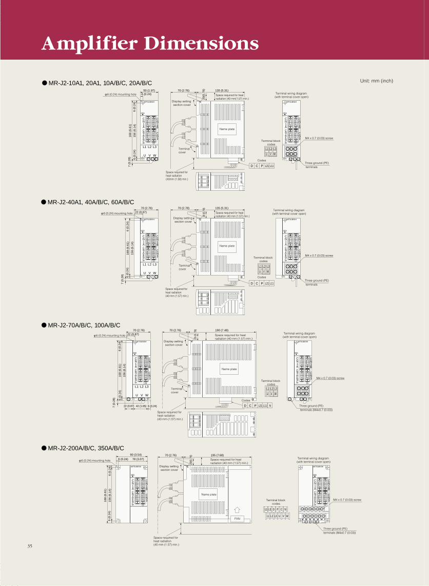
L1 L2 L3
U V W
CN3
CN1B
CN1ACN2ENC
( )
OPEN
MITSUBISHI
50 (1.97) 70 (2.76) 135 (5.31)6 (0.24)
6 (0
.24)
6 (0
.24)
156
(6.1
4)
168
(6.6
1)
20(0
.78)
D C P L21 L11
L1
U
L2
V
L3
W
CN3
CN1B
CN1ACN2ENC
( )
OPEN
MITSUBISHI
L1 L2 L3
U V W
CN3
CN1B
CN1ACN2ENC
( )
OPEN
MITSUBISHI
70 (2.76) 70 (2.78) 135 (5.31)22 (0.87)
6 (0
.24)
6 (0
.24)
156
(6.1
4)
168
(6.6
1)
20 (0
.79)
D C P L21 L11
L1
U
L2
V
L3
W
CN3
CN1B
CN1ACN2ENC
( )
OPEN
MITSUBISHI
70 (2.76) 190 (7.48)
20 (0
.79)
D C P L21 L11 N
L1
U
L2
V
L3
W
CN3
CN1B
CN1ACN2ENC
( )
OPEN
MITSUBISHI
L1 L2 L3
U V W
CN3
CN1B
CN1ACN2ENC
( )
OPEN
MITSUBISHI
70 (2.76)
22 (0.87) 42 (1.65) 6 (0.24)
22 (0.87)
6 (0
.24)
6 (0
.24)
7 (0
.28)
156
(6.1
4)
168
(6.6
1)
φ 6 (0.24) mounting hole
Display setting section cover
Space required for heat radiation (40 mm(1.57) min.)
Name plate
Terminal cover
Space required for heat radiation (40mm (1.58) min.)
Terminal wiring diagram (with terminal cover open)
Terminal block codes
Codes
M4 x 0.7 (0.03) screw
Three ground (PE) terminals
φ 6 (0.24) mounting hole
Display setting section cover
Space required for heat radiation (40 mm (1.57) min.)
Name plate
Terminal cover
Space required for heat radiation (40 mm (1.57) min.)
Terminal wiring diagram (with terminal cover open)
Terminal block codes
Codes
M4 x 0.7 (0.03) screw
Three ground (PE) terminals (M4x0.7 (0.03))
70 (2.76) 195 (7.68)
20(0
.78)
CN3
CN1B
CN1ACN2ENC
( )
OPEN
MITSUBISHI
90 (3.54)
78 (3.07)
6 (0
.24)
6 (0.24)
6 (0
.24)
156
(6.1
4)
168
(6.6
1)
φ 6 (0.24) mounting hole
Display setting section cover
Space required for heat radiation (40 mm (1.57) min.)
Name plate
Space required for heat radiation (40 mm (1.57) min.)
Terminal wiring diagram (with terminal cover open)
Three ground (PE)terminals (M4x0.7 (0.03))
FAN
MITSUBISHI
CN3
CN1B
CN1ACN2ENC
( )
OPEN
M4 x 0.7 (0.03) screw
L1 L2 L3
L21L11 D P C N
U V W
Terminal block codes
7 (0
.28)
7 (0
.28)
Amplifier Dimensions
MR-J2-40A1, 40A/B/C, 60A/B/C
MR-J2-10A1, 20A1, 10A/B/C, 20A/B/C
MR-J2-70A/B/C, 100A/B/C
MR-J2-200A/B/C, 350A/B/C
35
Unit: mm (inch)
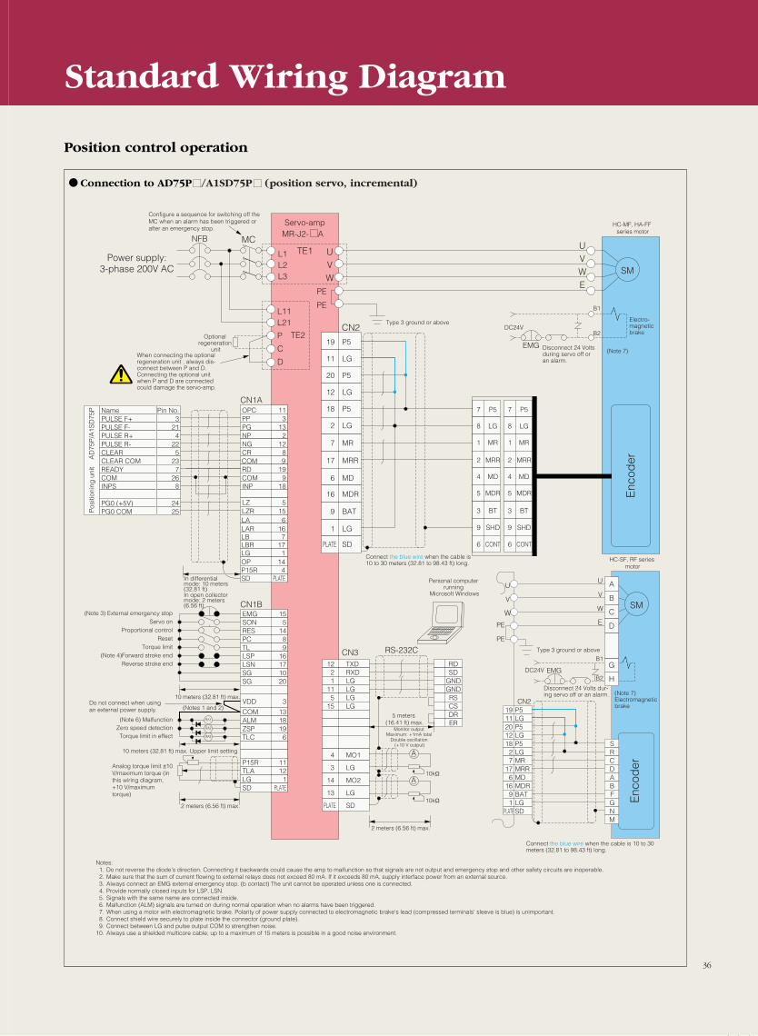
36
A
RA1
RA2
RA3
CN1BEMG 15
12 TXD RD
P519LG11P520LG12P518LG2MR7MRR17MD6MDR16BAT9LG1SDPLATE
2 RXD SD1 LG GND
11 LG GND5 LG RS
15 LG CSDR
4 MO1
3 LG
14 MO2
13 LG
PLATE SD
ER
SON 5RES 14PC 8TL 9LSP 16LSN 17SG 10SG 20
VDD 3
COM 13ALM 18ZSP 19TLC 6
P15R 11TLA 12LG 1SD PLATE
SM
UVW
UVW
E
7 P5 7 P5
8 LG 8 LG
1 MR 1 MR
2 MRR 2 MRR
4 MD 4 MD
5 MDR 5 MDR
3 BT 3 BT
9 SHD 9 SHD
6 CONT 6 CONT
L1L2L3
L11L21
P
C
D
TE1MCNFB
TE2
PE
PE
CN2
CN3
CN2
RS-232C
CN1A
MR-J2- A
19 P5
11 LG
20 P5
12 LG
18 P5
2 LG
7 MR
17 MRR
6 MD
16 MDR
9 BAT
1 LG
PLATE SD
OPC 11Name Pin No.PULSE F+ 3PULSE F- 21PULSE R+ 4PULSE R- 22CLEAR 5CLEAR COM 23READY 7COM 26INPS 8
PG0 (+5V) 24PG0 COM 25
PP 3PG 13NP 2NG 12CR 8
RD 19COM 9INP 18
LZ 5LZR 15LA 6
COM 9
LAR 16LB 7LBR 17LG 1OP 14P15R 4SD PLATE
A
AU
BV
CW
E
U
V
W
PE
PE
SRCDABFGNM
B1
B2
EMG
DC24V
B1
B2EMGDC24V
G
H
Configure a sequence for switching off the MC when an alarm has been triggered or after an emergency stop.
Power supply:3-phase 200V AC
Servo-amp HC-MF, HA-FF series motor
When connecting the optional regeneration unit , always dis-connect between P and D. Connecting the optional unit when P and D are connected could damage the servo-amp.
Optional regeneration
unit
Type 3 ground or above
Disconnect 24 Volts during servo off or an alarm.
Electro-magnetic brake
Pos
ition
ing
uni
t A
D75
P/A
1SD
75P
In differential mode: 10 meters (32.81 ft)In open collector mode: 2 meters (6.56 ft)
Connect the blue wire when the cable is 10 to 30 meters (32.81 to 98.43 ft) long.
(Note 3) External emergency stopServo on
Proportional controlReset
Torque limit(Note 4)Forward stroke end
Reverse stroke end
(Note 6) MalfunctionZero speed detectionTorque limit in effect
Do not connect when using an external power supply.
Analog torque limit ±10 V/maximum torque (in this wiring diagram, +10 V/maximum torque)
10 meters (32.81 ft) max.
(Notes 1 and 2)
10 meters (32.81 ft) max. Upper limit setting
2 meters (6.56 ft) max.
5 meters (16.41 ft) max.
Monitor outputMaximum: +1mA total
Double oscillation (+10 V output)
10kΩ
10kΩ
2 meters (6.56 ft) max.
Personal computer running
Microsoft Windows
Type 3 ground or above
Disconnect 24 Volts dur-ing servo off or an alarm.
Connect the blue wire when the cable is 10 to 30 meters (32.81 to 98.43 ft) long.
Enc
oder
Enc
oder
Notes: 1. Do not reverse the diode's direction. Connecting it backwards could cause the amp to malfunction so that signals are not output and emergency stop and other safety circuits are inoperable.2. Make sure that the sum of current flowing to external relays does not exceed 80 mA. If it exceeds 80 mA, supply interface power from an external source.3. Always connect an EMG external emergency stop. (b contact) The unit cannot be operated unless one is connected.4. Provide normally closed inputs for LSP, LSN.5. Signals with the same name are connected inside.6. Malfunction (ALM) signals are turned on during normal operation when no alarms have been triggered.7. When using a motor with electromagnetic brake. Polarity of power supply connected to electromagnetic brake's lead (compressed terminals' sleeve is blue) is unimportant.8. Connect shield wire securely to plate inside the connector (ground plate).9. Connect between LG and pulse output COM to strengthen noise.
10. Always use a shielded multicore cable; up to a maximum of 15 meters is possible in a good noise environment.
HC-SF, RF series motor
(Note 7)
(Note 7)Electromagnetic brake
SM
D
Connection to AD75PM/A1SD75PM (position servo, incremental)
Position control operation
Standard Wiring Diagram
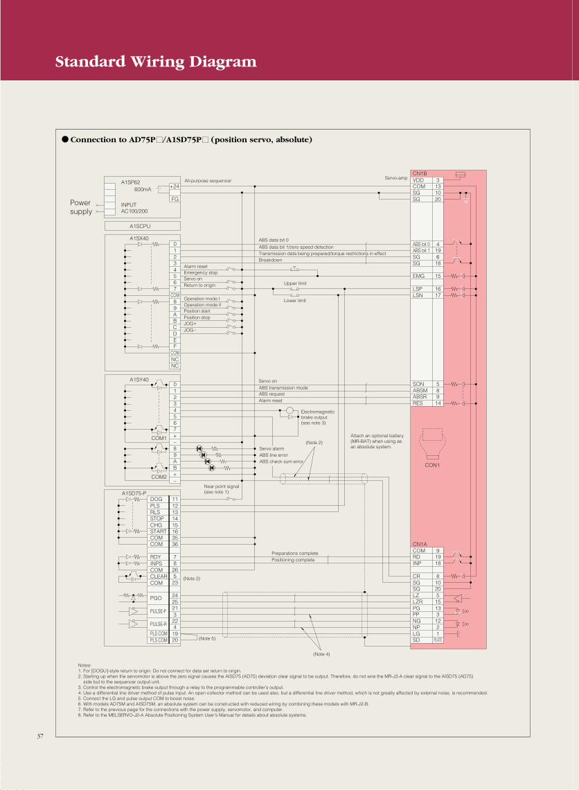
Powersupply
A1SP62
A1SCPU
A1SX40
A1SY40
A1SD75-P
COM1
COM2
INPUTAC100/200
600mA +2424GFG
01234567
COM89ABCDEF
COMNCNC
1112131415163536
DOGPLSRLSSTOPCHG
RDYINPSCOMCLEARCOM
PULSE-F
PGO
PULSE-R
PLS COMPLS COM
STARTCOMCOM
7826523
24252132241920
01234567+-89AB+-
CN1BVDDCOMSGSG
3131020
ABS bit 0ABS bit 1SGSG
419618
LSPLSN
1617
SONABSM
58
ABSRRES
914
CN1ACOM 9RDINP
1918
CRSG
810
SGLZ
205
LZRPG
1513
PPNG
312
NPLG
21
SD PLATE
EMG 15
CON1
Near point signal (see note 1)
(Note 2)
(Note 2)
Electromagnetic brake output (see note 3)
(Note 5)
(Note 4)
Notes: 1. For [DOGU]-style return to origin. Do not connect for data set return to origin. 2. Starting up when the servomotor is above the zero signal causes the AISD75 (AD75) deviation clear signal to be output. Therefore, do not wire the MR-J2-A clear signal to the AISD75 (AD75) side but to the sequencer output unit. 3. Control the electromagnetic brake output through a relay to the programmable controller's output. 4. Use a differential line driver method of pulse input. An open collector method can be used also, but a differential line driver method, which is not greatly affected by external noise, is recommended. 5. Connect the LG and pulse output COM to boost noise. 6. With models AD75M and AISD75M, an absolute system can be constructed with reduced wiring by combining these models with MR-J2-B. 7. Refer to the previous page for the connections with the power supply, servomotor, and computer. 8. Refer to the MELSERVO-J2-A Absolute Positioning System User's Manual for details about absolute systems.
All-purpose sequencerServo-amp
ABS data bit 0
Servo onABS transmission modeABS requestAlarm reset
ABS data bit 1/zero speed detectionTransmission data being prepared/torque restrictions in effectBreakdown
Upper limit
Alarm resetEmergency stopServo onReturn to origin
Operation mode IOperation mode IIPosition startPosition stopJOG+
JOG-
Lower limit
Servo alarmABS line errorABS check sum error
Attach an optional battery (MR-BAT) when using as an absolute system.
Preparations completePositioning complete
37
Connection to AD75PM/A1SD75PM (position servo, absolute)
Standard Wiring Diagram
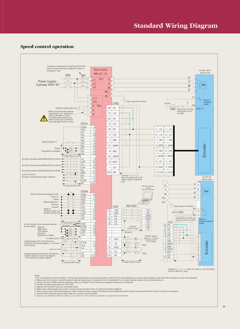
Speed control operation
A
RA1
(Notes 1 and 2)
RA2
RA3
CN1BEMG 15
12 TXD RD
P520LG12P520LG12P518LG2MR7MRR17MD6MDR16BAT9LG1SDPLATE
2 RXD SD1 LG GND
11 LG GND5 LG RS
15 LG CSDR
4 MO1
3 LG
14 MO2
13 LG
PLATE SD
ER
SON 5RES 14SP2 7ST1 8ST2 9LSP 16LSN 17SG 10SG 20
VDD 3COM 13ALM 18ZSP 19TLC 6
P15R 11TLA 12LG 1
VC 2SD PLATE
RA1
RA2
SM
UVW
UVW
E
7 P5 7 P5
8 LG 8 LG
1 MR 1 MR
2 MRR 2 MRR
4 MD 4 MD
5 MDR 5 MDR
3 BT 3 BT
9 SHD 9 SHD
6 CONT 6 CONT
L1L2L3
L11
Optional regeneration unit
L21
P
C
D
TE1MCNFB
TE2
PE
PE
CN2
CN3
CN2
RS-232C
CN1A
MR-J2- A
20 P5
12 LG
20 P5
12 LG
18 P5
2 LG
7 MR
17 MRR
6 MD
16 MDR
9 BAT
1 LG
PLATE SD
COM 9OPC 11PP 3PG 13NP 2NG 12SP1 8SG 10RD 19SA 18SG 20
LZ 5LZR 15LA 6LAR 16LB 7LBR 17LG 1OP 14P15R 4SD PLATE
A
AU
BV
CW
DE
U
V
W
PE
PE
SM
SRCDABFGNM
B1
(Note 7)
B2
EMG
DC24V
B1
B2EMGDC24V
G
H
Configure a sequence for switching off the MC when an alarm has been triggered or after an emergency stop.
When connecting the optional regeneration unit , always dis-connect between P and D. Connecting the optional unit when P and D are connected could damage the servo-amp.
Power supply: 3-phase 200V AC
Encoder Z-phase pulse (differential line driver)
Encoder A-phase pulse (differential line driver)
Encoder B-phase pulse (differential line driver)
Encoder Z-phase pulse (open collector)control common
10 meters (32.81 ft max.)
2 meters (6.56 ft max.)
5 meters (16.41 ft max.)
2 meters (6.56 ft max.)
10kΩ
10kΩ
2 meters (6.56 ft max.)
10 meters (32.81 ft ) max.
10 meters (32.81 ft max.) Upper limit setting
Upper limit setting
Speed selection 1
Ready
Preparations complete
Connect the blue wire when the cable is10 to 30 meters (32.81 to 98.43 ft) long.
Disconnect 24 Volts during servo off or an alarm.
Electro-magnetic brake
(Note 3) External emergency stop Servo on
Reset Speed selection 2
Reverse Forward
Do not connect when using an external power supply.
(Note 4)Forward stroke endReverse stroke end
(Note 6)Malfunction Zero speed detectionSpeed limit in effect
Analog torque limit ±10 V/maximum torque (in this wiring diagram, +10 V/maxi-mum torque)
Analog speed command ±10 V/maximum rotation speed (in this wiring diagram, +10 V/maximum rotation speed)
Monitor output Maximum: +1mA total
Double oscillation (+10 V output)
Personal computer running
Microsoft Windows
Type 3 ground or above
Type 3 ground or above
Disconnect 24 Volts dur-ing servo off or an alarm. (Note 7)
Electromagnetic brake
Connect the blue wire when the cable is 10 to 30 meters (32.81 to 98.43 ft) long.
Enc
oder
Enc
oder
Notes:1. Do not reverse the diode's direction. Connecting it backwards could cause the amp to malfunction so that signals are not output and emergency stop and other protection circuits are inoperable.2. Make sure that the sum of current flowing to external relays does not exceed 80 mA. If it exceeds 80 mA, supply interface power from an external source.3. Always connect an EMG external emergency stop. (b contact) The unit cannot be operated unless one is connected.4. Provide normally closed inputs for LSP, LSN.5. Signals with the same name are connected inside.6. Malfunction (ALM) signals are turned on during normal operation when no alarms have been triggered.7. When using a motor with electromagnetic brake. Polarity of power supply connected to electromagnetic brake's lead (compressed terminals' sleeve is blue) is unimportant.8. Connect shield wire securely to plate inside the connector (ground plate).9. Always use a shielded multicore cable; up to a maximum of 15 meters is possible in a good noise environment.
Servo-amp HC-MF, HA-FF series motor
HC-SF, RF series motor
(Note 8)
38
Standard Wiring Diagram
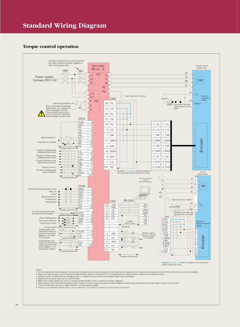
A
RA1
RA2
RA3
CN1BEMG 15
12 TXD RD
P520LG12P520LG12P518LG2MR7MRR17MD6MDR16BAT9LG1SDPLATE
2 RXD SD1 LG GND
11 LG GND5 LG RS
15 LG CSDR
4 MO1
3 LG
14 MO2
13 LG
PLATE SD
ER
SON 5RES 14SP2 7ST1 8ST2 9SG 10SG 20
VDD 3COM 13ALM 18ZSP 19TLC 6
P15R 11TC 12LG 1
VLA 2SD PLATE
RA1
SM
UVW
UVW
E
7 P5 7 P5
8 LG 8 LG
1 MR 1 MR
2 MRR 2 MRR
4 MD 4 MD
5 MDR 5 MDR
3 BT 3 BT
9 SHD 9 SHD
6 CONT 6 CONT
L1L2L3
L11L21
P
C
D
TE1MCNFB
TE2
PE
PE
CN2
CN3
CN2
RS-232C
CN1A
MR-J2- AServo-amp
20 P5
12 LG
20 P5
12 LG
18 P5
2 LG
7 MR
17 MRR
6 MD
16 MDR
9 BAT
1 LG
PLATE SD
COM 9OPC 11PP 3PG 13NP 2NG 12SP1 8SG 10RD 19SG 20
LZ 5LZR 15LA 6LAR 16LB 7LBR 17LG 1OP 14P15R 4SD PLATE
A
AU
BV
CW
DE
U
V
W
PE
PE
SM
SRCDABFGNM
B1
Electro-magneticbrake
HC-MF, HA-FFseries motor
(Note 6)
B2
EMG
DC24V
B1
B2EMGDC24V
G
H
Configure a sequence for switching off the MC when an alarm has been triggered or after an emergency stop.
When connecting the optional regeneration unit , always dis-connect between P and D. Connecting the optional unit when P and D are connected could damage the servo-amp.
Power supply: 3-phase 200 V AC
Type 3 ground or above
Type 3 ground or above
Connect the blue wire when the cable is 10 to 30 meters (32.81 to 98.43 ft) long.
Personal computer running
Microsoft Windows
Disconnect 24 Volts during servo off or an alarm.
Enc
oder
Enc
oder
Disconnect 24 Volts dur-ing servo off or an alarm.
Monitor outputMaximum: +1mA total
Double oscillation(+10 V output)
Speed selection 1
Optional regeneration unit
Preparations complete
Encoder Z-phase pulse(differential line driver)
Encoder A-phase pulse(differential line driver)
Encoder B-phase pulse(differential line driver)
Encoder Z-phase pulse(open collector)
Control common
10 meters (32.81 ft) max.
2 meters (6.56 ft) max.
10 meters (32.81 ft) max.
10 meters (32.81 ft) max.
5 meters (16.41 ft) max.
2 meters (6.56 ft) max.
2 meters (6.56 ft) max.
(Note 3) External emergency stop Servo on
Reset Speed selection 2
Forward start Reverse start
(Note 5) Malfunction Zero speed detection Torque limit in effect
Do not connect when using an external power supply.
Analog torque com-mand ±8 V/maximum torque (in this wiring diagram, +8 V/maxi-mum torque)
Analog speed com-mand ±10 V/maximum rotation speed (in this wiring diagram, +10 V/maximum rotation
(Notes 1 and 2)
Upper limit setting
Upper limit setting10kΩ
10kΩ
Connect the blue wire when the cable is 10 to 30 meters (32.81 to 98.43 ft) long.
Notes: 1. Do not reverse the diode's direction. Connecting it backwards could cause the amp to malfunction so that signals are not output and emergency stop and other protection circuits are inoperable.2. Make sure that the sum of current flowing to external relays does not exceed 80 mA. If it exceeds 80 mA, supply interface power from an external source.3. Always connect an EMG external emergency stop. (b contact) The unit cannot be operated unless one is connected.4. Signals with the same name are connected inside.5. Malfunction (ALM) signals are turned on during normal operation when no alarms have been triggered.6. When using a motor with electromagnetic brake. Polarity of power supply connected to electromagnetic brake's lead (compressed terminals' sleeve is blue) is unimportant.7. Connect shield wire securely to plate inside the connector (ground plate).8. Always use a shielded multicore cable; up to a maximum of 15 meters is possible in a good noise environment.
HC-SFseries motor
(Note 6)Electromagnetic brake
(Note 8)
Torque control operation
39
Standard Wiring Diagram
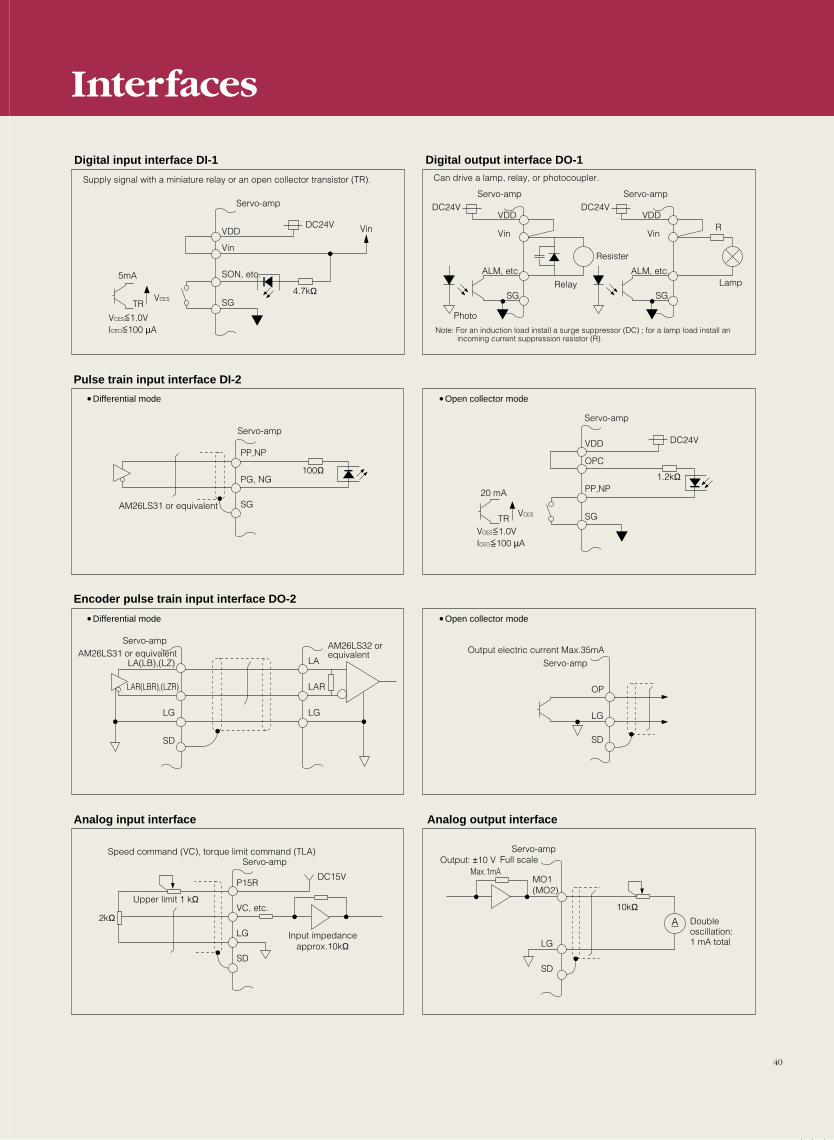
A
VDD
Digital input interface DI-1
VDD
VDD
OPC
PP,NP
SG
OP
LGLG
SD
LG
SD
MO1(MO2)
LG
VC, etc.
P15R
LAR
LA
LG
SD
LAR(LBR),(LZR)
LA(LB),(LZ)
SD
VDD
Vin
Vin Vin Vin
SON, etc.
SG
SG
PG, NG
PP,NP
DC24V
DC24V
DC24V
DC24V
4.7kΩTR
VCES
VCES
VCES=1.0VICEO=100 µA
<<
100Ω
ALM, etc. ALM, etc.
SG SG
R
Resister
1.2kΩ
20 mA
TRVCES=1.0VICEO=100 µA
<<
Output electric current Max.35mAAM26LS31 or equivalentAM26LS32 or equivalent
2kΩ
DC15V
Input impedanceapprox.10kΩ
Upper limit 1 kΩ
Max.1mA
10kΩ
Supply signal with a miniature relay or an open collector transistor (TR).
5mA
Servo-amp
Digital output interface DO-1Can drive a lamp, relay, or photocoupler.
Servo-amp Servo-amp
Note: For an induction load install a surge suppressor (DC) ; for a lamp load install an incoming current suppression resistor (R).
Pulse train input interface DI-2
Encoder pulse train input interface DO-2
Analog input interface Analog output interface
•Differential mode •Open collector mode
•Differential mode •Open collector mode
Servo-ampServo-amp
Servo-amp
Servo-amp
Servo-amp
AM26LS31 or equivalent
Speed command (VC), torque limit command (TLA)Output: ±10 V
Servo-ampFull scale
Double oscillation: 1 mA total
Photo
LampRelay
Interfaces
40
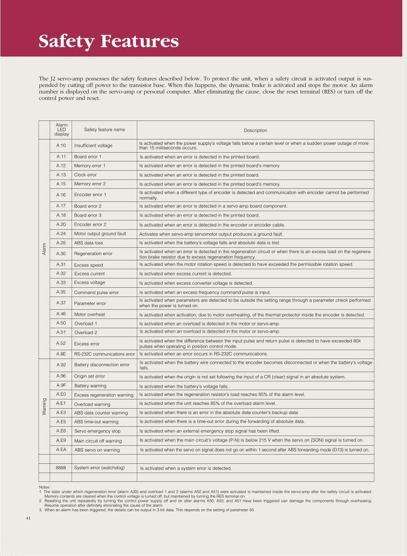
Safety Features
The J2 servo-amp possesses the safety features described below. To protect the unit, when a safety circuit is activated output is sus-pended by cutting off power to the transistor base. When this happens, the dynamic brake is activated and stops the motor. An alarmnumber is displayed on the servo-amp or personal computer. After eliminating the cause, close the reset terminal (RES) or turn off thecontrol power and reset.
Safety feature name DescriptionAlarmLED
display
Is activated when the power supply's voltage falls below a certain level or when a sudden power outage of morethan 15 milliseconds occurs.
Is activated when an error is detected in the printed board.
Is activated when an overload is detected in the motor or servo-amp.
Insufficient voltage
Board error 1
Memory error 1 Is activated when an error is detected in the printed board's memory.
Clock error Is activated when an error is detected in the printed board.
Memory error 2 Is activated when an error is detected in the printed board's memory.
Encoder error 1 Is activated when a different type of encoder is detected and communication with encoder cannot be performednormally.
Board error 2 Is activated when an error is detected in a servo-amp board component.
Board error 3 Is activated when an error is detected in the printed board.
Encoder error 2 Is activated when an error is detected in the encoder or encoder cable.
ABS data loss Is activated when the battery's voltage falls and absolute data is lost.
Regeneration error Is activated when an error is detected in the regeneration circuit or when there is an excess load on the regenera-tion brake resistor due to excess regeneration frequency.
Excess speed Is activated when the motor rotation speed is detected to have exceeded the permissible rotation speed.
Excess current Is activated when excess current is detected.
Excess voltage Is activated when excess converter voltage is detected.
Command pulse error Is activated when an excess frequency command pulse is input.
Parameter errorIs activated when parameters are detected to be outside the setting range through a parameter check performedwhen the power is turned on.
Motor overheat Is activated when activation, due to motor overheating, of the thermal protector inside the encoder is detected.
Overload 1 Is activated when an overload is detected in the motor or servo-amp.
Is activated when an error occurs in RS-232C communications.
Overload 2
Excess errorIs activated when the difference between the input pulse and return pulse is detected to have exceeded 80k pulses when operating in position control mode.
RS-232C communications error
Battery disconnection error Is activated when the battery wire connected to the encoder becomes disconnected or when the battery's voltagefalls.
Origin set error Is activated when the origin is not set following the input of a CR (clear) signal in an absolute system.
Battery warning Is activated when the battery's voltage falls.
Excess regeneration warning Is activated when the regeneration resistor's load reaches 85% of the alarm level.
Is activated when the unit reaches 85% of the overload alarm level.Overload warning
ABS data counter warning Is activated when there is an error in the absolute data counter's backup data.
ABS time-out warning Is activated when there is a time-out error during the forwarding of absolute data.
Servo emergency stop Is activated when an external emergency stop signal has been lifted.
Main circuit off warning Is activated when the main circuit's voltage (P-N) is below 215 V when the servo on (SON) signal is turned on.
ABS servo on warning Is activated when the servo on signal does not go on within 1 second after ABS forwarding mode (D13) is turned on.
System error (watchdog) Is activated when a system error is detected.
Notes:1. The state under which regeneration error (alarm A30) and overload 1 and 2 (alarms A50 and A51) were activated is maintained inside the servo-amp after the safety circuit is activated.
Memory contents are cleared when the control voltage is turned off, but maintained by turning the RES terminal on.2. Resetting the unit repeatedly by turning the control power supply off and on after alarms A30, A50, and A51 have been triggered can damage the components through overheating.
Resume operation after definitely eliminating the cause of the alarm.3. When an alarm has been triggered, the details can be output in 3-bit data. This depends on the setting of parameter 50.
A.10
A.11
A.12
A.13
A.15
A.16
A.17
A.18
A.20
Motor output ground fault Activates when servo-amp servomotor output produces a ground fault.A.24
A.25
A.30
A.31
A.32
A.33
A.35
A.37
A.46
A.50
A.51
A.52
A.8E
A.92
A.96
A.9F
A.E6
A.E0
A.E1
A.E3
A.E5
A.E9
A.EA
8888
Ala
rm
War
ning
41
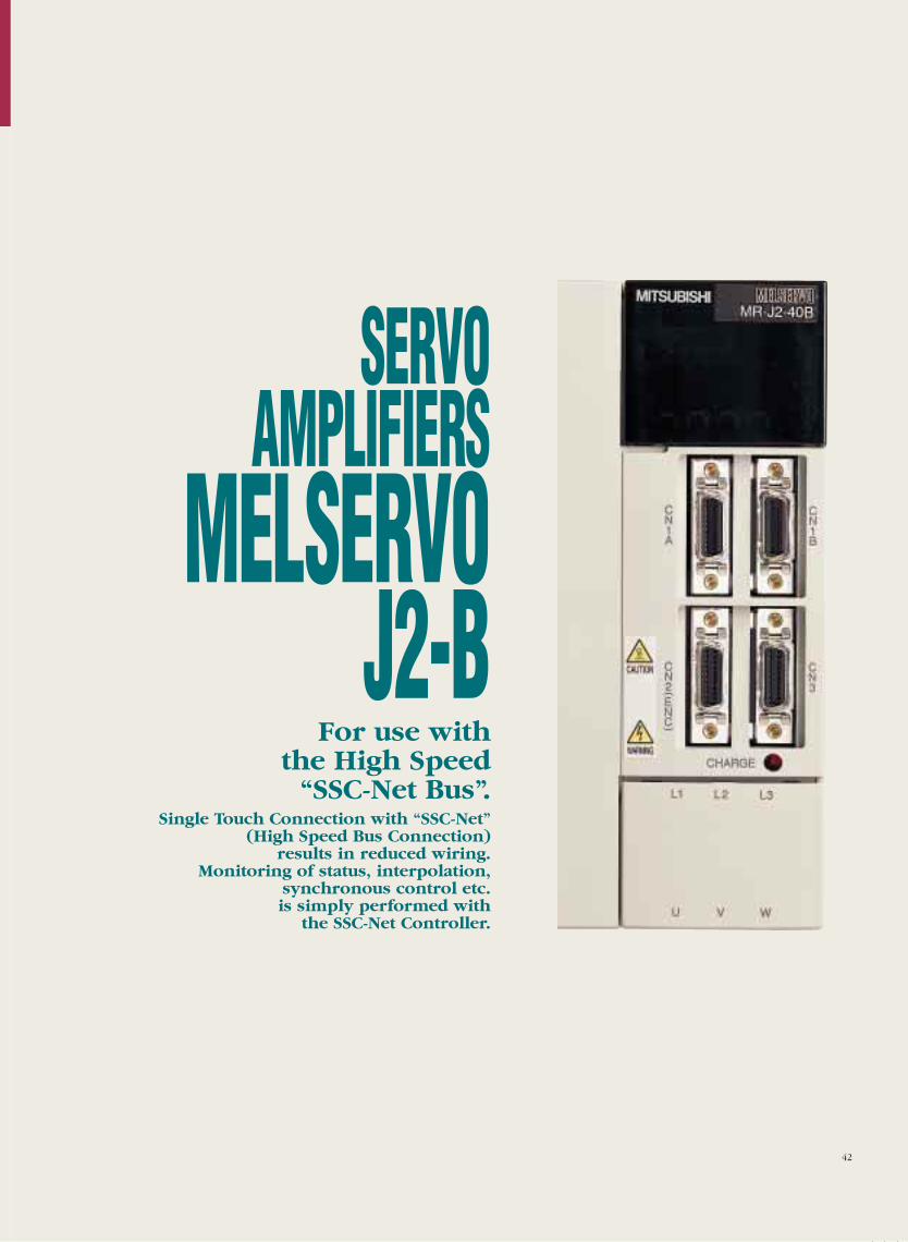
SERVOAMPLIFIERS
MELSERVOJ2-B
42
For use with the High Speed
“SSC-Net Bus”.Single Touch Connection with “SSC-Net”
(High Speed Bus Connection) results in reduced wiring.
Monitoring of status, interpolation, synchronous control etc. is simply performed with
the SSC-Net Controller.
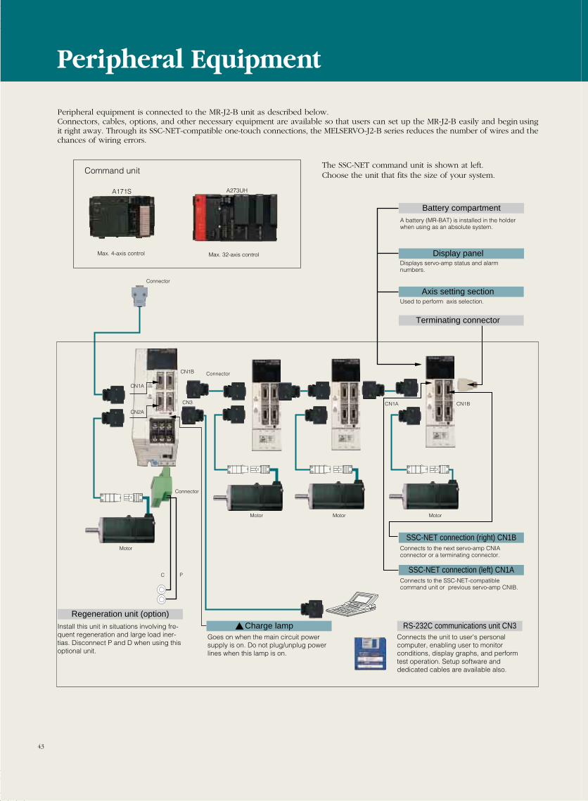
Battery compartment
Display panel
Axis setting section
Terminating connector
SSC-NET connection (right) CN1B
SSC-NET connection (left) CN1A
RS-232C communications unit CN3Charge lamp
A battery (MR-BAT) is installed in the holder when using as an absolute system.
Displays servo-amp status and alarm numbers.
Used to perform axis selection.
Connects to the next servo-amp CNIA connector or a terminating connector.
Connects to the SSC-NET-compatible command unit or previous servo-amp CNIB.
Connector
CN1A
CN1B
CN3
C P
CN2A
Connector
Motor Motor Motor
Motor
Install this unit in situations involving fre-quent regeneration and large load iner-tias. Disconnect P and D when using this optional unit.
Goes on when the main circuit power supply is on. Do not plug/unplug power lines when this lamp is on.
Connects the unit to user's personal computer, enabling user to monitor conditions, display graphs, and perform test operation. Setup software and dedicated cables are available also.
CN1A CN1B
Connector
Command unit
A273UHA171S
Max. 4-axis control Max. 32-axis control
Regeneration unit (option)
Peripheral equipment is connected to the MR-J2-B unit as described below.Connectors, cables, options, and other necessary equipment are available so that users can set up the MR-J2-B easily and begin usingit right away. Through its SSC-NET-compatible one-touch connections, the MELSERVO-J2-B series reduces the number of wires and thechances of wiring errors.
The SSC-NET command unit is shown at left.Choose the unit that fits the size of your system.
Peripheral Equipment
43
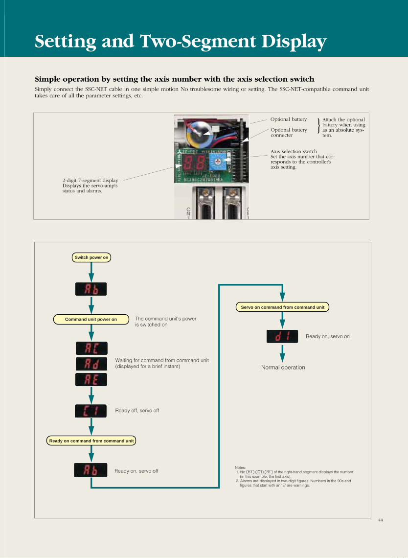
44
Switch power on
Command unit power on
Servo on command from command unit
Ready on command from command unit
Ready on, servo on
Normal operation
The command unit's power is switched on
Waiting for command from command unit (displayed for a brief instant)
Ready off, servo off
Ready on, servo offNotes: 1. No of the right-hand segment displays the number
(in this example, the first axis). 2. Alarms are displayed in two-digit figures. Numbers in the 90s and
figures that start with an "E" are warnings.
b1 C1 d1, ,
Simple operation by setting the axis number with the axis selection switchSimply connect the SSC-NET cable in one simple motion No troublesome wiring or setting. The SSC-NET-compatible command unittakes care of all the parameter settings, etc.
Optional battery Attach the optionalbattery when usingas an absolute sys-tem.
Axis selection switchSet the axis number that cor-responds to the controller'saxis setting.
2-digit 7-segment displayDisplays the servo-amp's status and alarms.
Optional batteryconnecter
Setting and Two-Segment Display
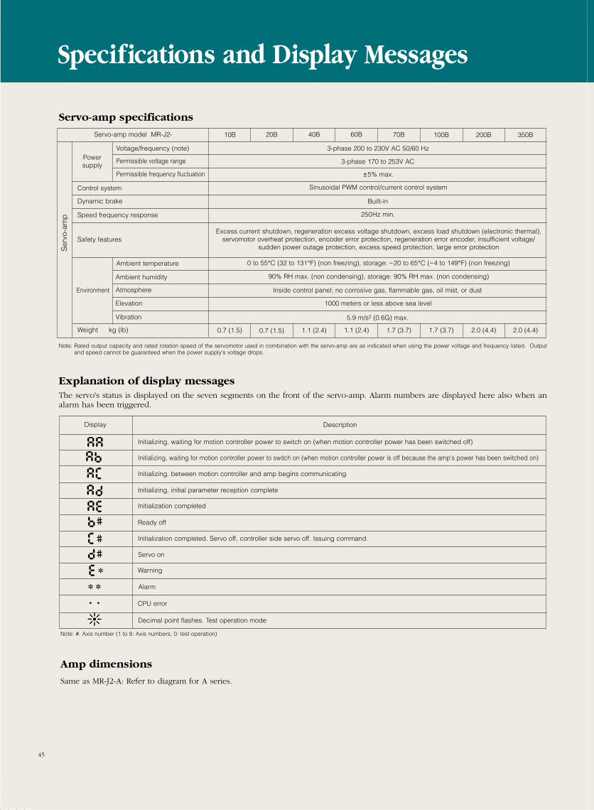
45
Servo-amp model MR-J2-
Power supply
Voltage/frequency (note)
Permissible voltage range
Permissible frequency fluctuation
3-phase 200 to 230V AC 50/60 Hz
3-phase 170 to 253V AC
±5% max.
Control system
Speed frequency response
Safety features
Dynamic brake
Sinusoidal PWM control/current control system
250Hz min.
Excess current shutdown, regeneration excess voltage shutdown, excess load shutdown (electronic thermal),servomotor overheat protection, encoder error protection, regeneration error encoder, insufficient voltage/
sudden power outage protection, excess speed protection, large error protection
0 to 55°C (32 to 131°F) (non freezing), storage: −20 to 65°C (−4 to 149°F) (non freezing)
Ser
vo-a
mp
Environment
Ambient temperature
Ambient humidity
Atmosphere
Elevation
Vibration
90% RH max. (non condensing), storage: 90% RH max. (non condensing)
Inside control panel; no corrosive gas, flammable gas, oil mist, or dust
1000 meters or less above sea level
5.9 m/s2 (0.6G) max.
10B 20B 40B 60B 70B 100B 200B 350B
Built-in
Weight kg (lb)
Note: Rated output capacity and rated rotation speed of the servomotor used in combination with the servo-amp are as indicated when using the power voltage and frequency listed. Outputand speed cannot be guaranteed when the power supply's voltage drops.
Explanation of display messagesThe servo's status is displayed on the seven segments on the front of the servo-amp. Alarm numbers are displayed here also when analarm has been triggered.
Display Description
Initializing, waiting for motion controller power to switch on (when motion controller power has been switched off)
Initializing, waiting for motion controller power to switch on (when motion controller power is off because the amp's power has been switched on)
Initializing, between motion controller and amp begins communicating
Initializing, initial parameter reception complete
Initialization completed
Ready off
Initialization completed, Servo off, controller side servo off. Issuing command.
Servo on
Warning
Alarm
CPU error
Decimal point flashes. Test operation mode
Note: #: Axis number (1 to 8: Axis numbers, 0: test operation)
Amp dimensions
Same as MR-J2-A: Refer to diagram for A series.
Specifications and Display Messages
Servo-amp specifications
0.7 (1.5) 0.7 (1.5) 1.1 (2.4) 1.1 (2.4) 1.7 (3.7) 1.7 (3.7) 2.0 (4.4) 2.0 (4.4)
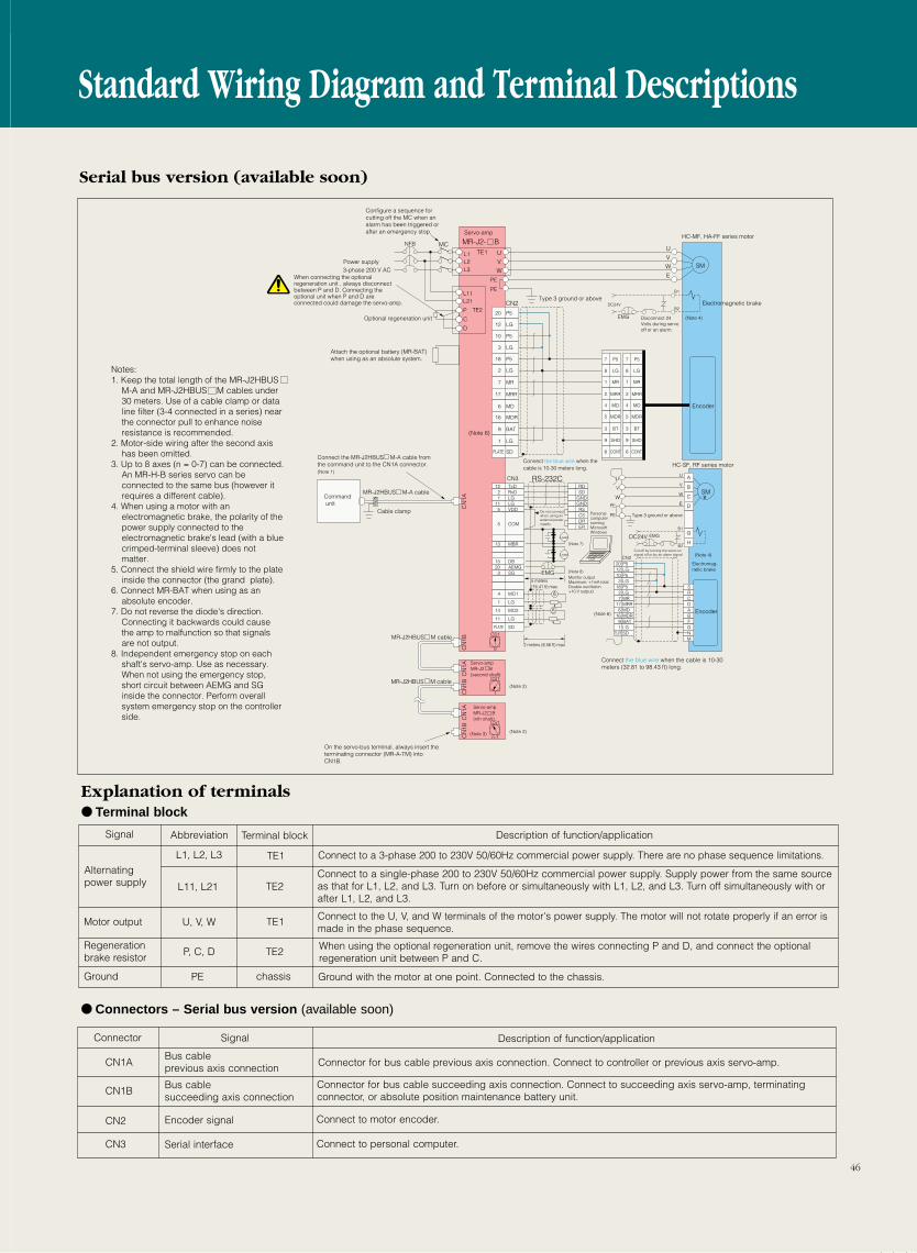
46
Signal Abbreviation Terminal block Description of function/application
Connect to a 3-phase 200 to 230V 50/60Hz commercial power supply. There are no phase sequence limitations.
Explanation of terminals Terminal block
Alternatingpower supply
Connect to a single-phase 200 to 230V 50/60Hz commercial power supply. Supply power from the same sourceas that for L1, L2, and L3. Turn on before or simultaneously with L1, L2, and L3. Turn off simultaneously with orafter L1, L2, and L3.
Motor output
Regenerationbrake resistor
Connect to the U, V, and W terminals of the motor's power supply. The motor will not rotate properly if an error ismade in the phase sequence.
When using the optional regeneration unit, remove the wires connecting P and D, and connect the optionalregeneration unit between P and C.
Ground with the motor at one point. Connected to the chassis.Ground
Connector Signal Description of function/application
CN1A
CN1B
CN2
Bus cable previous axis connection
Bus cable succeeding axis connection
Encoder signal
Serial interfaceCN3
Connector for bus cable previous axis connection. Connect to controller or previous axis servo-amp.
Connector for bus cable succeeding axis connection. Connect to succeeding axis servo-amp, terminating connector, or absolute position maintenance battery unit.
Connect to motor encoder.
Connect to personal computer.
Connectors – Serial bus version (available soon)
L1, L2, L3 TE1
L11, L21
U, V, W
P, C, D
PE
TE2
TE1
TE2
chassis
Standard Wiring Diagram and Terminal Descriptions
A
12 TxD RD
P520LG12P510LG3P518LG2MR7MRR17MD6MDR16BAT9LG1SDPLATE
2 RxD SD1 LG GND
11 LG GND5 VDD
13 MBR
15 DB20 AEMG
3 SG
4 MO1
1 LG
14 MO2
11 LG
PLATE SD
RS
5 COM
CSDRER
SM
UVW
UVW
E
7 P5 7 P5
8 LG 8 LG
1 MR 1 MR
2 MRR 2 MRR
4 MD 4 MD
5 MDR 5 MDR
3 BT 3 BT
9 SHD 9 SHD
6 CONT 6 CONT
L1L2L3
L11L21
P
C
D
TE1MCNFB
TE2
PE
PE
CN2
CN3
CN2
RS-232C
MR-J2- B
20 P5
12 LG
10 P5
3 LG
18 P5
2 LG
7 MR
17 MRR
6 MD
16 MDR
9 BAT
1 LG
PLATE SD
A
AU
BV
CW
DE
U
V
W
PE
PE
SM
SRCDABFGNM
B1
B2
EMG
DC24V
B1
B2
EMGDC24VG
H
1
CS1
CN
1AC
N1A
CN
1BC
N1B
n-1
CS1
CN
1AC
N1B
0
CS1
EMG
Configure a sequence for cutting off the MC when an alarm has been triggered or after an emergency stop. Servo-amp
Power supply3-phase 200 V AC
Optional regeneration unit
Attach the optional battery (MR-BAT) when using as an absolute system.
Connect the MR-J2HBUS M-A cable from the command unit to the CN1A connector.(Note 1)
Command unit
MR-J2HBUS M-A cable
Cable clamp
MR-J2HBUS M cable
MR-J2HBUS M cable
On the servo-bus terminal, always insert the terminating connector (MR-A-TM) into CN1B.
(Note 6)
Servo-amp MR-J2 B (second shaft)
Servo-amp MR-J2 B (nth shaft)
(Note 3)
(Note 2)
(Note 2)
Type 3 ground or above
Connect the blue wire when the cable is 10-30 meters long.
Do not connect when using an external power supply.
(Note 7)
(Note 8)
Load
Load
5 meters (16.41 ft) max.
Monitor outputMaximum: +1mA totalDouble oscillation +10 V output)
2 meters (6.56 ft) max.
Personal computer running Microsoft Windows
HC-MF, HA-FF series motor
Electromagnetic brake
Disconnect 24 Volts during servo off or an alarm.
(Note 4)
Encoder
Encoder
HC-SF, RF series motor
Type 3 ground or above
Cut off by turning the servo-on signal off or by an alarm signal. (Note 4)
Electromag-netic brake
(Note 6)
Connect the blue wire when the cable is 10-30 meters (32.81 to 98.43 ft) long.
When connecting the optional regeneration unit , always disconnect between P and D. Connecting the optional unit when P and D are connected could damage the servo-amp.
VV
Notes:1. Keep the total length of the MR-J2HBUS
M-A and MR-J2HBUS M cables under 30 meters. Use of a cable clamp or data line filter (3-4 connected in a series) near the connector pull to enhance noise resistance is recommended.
2. Motor-side wiring after the second axis has been omitted.
3. Up to 8 axes (n = 0-7) can be connected. An MR-H-B series servo can be connected to the same bus (however it requires a different cable).
4. When using a motor with an electromagnetic brake, the polarity of the power supply connected to the electromagnetic brake's lead (with a blue crimped-terminal sleeve) does not matter.
5. Connect the shield wire firmly to the plate inside the connector (the grand plate).
6. Connect MR-BAT when using as an absolute encoder.
7. Do not reverse the diode's direction. Connecting it backwards could cause the amp to malfunction so that signals are not output.
8. Independent emergency stop on each shaft's servo-amp. Use as necessary. When not using the emergency stop, short circuit between AEMG and SG inside the connector. Perform overall system emergency stop on the controller side.
Serial bus version (available soon)
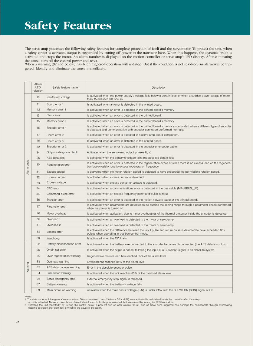
47
Safety feature name DescriptionAlarmLED
display
Is activated when the power supply's voltage falls below a certain level or when a sudden power outage of morethan 15 milliseconds occurs.
Is activated when an error is detected in the printed board's memory.
Insufficient voltage
Memory error 1
Memory error 2 Is activated when an error is detected in the printed board's memory.
Encoder error 1 Is activated when an error is detected in the printed board's memory.Is activated when a different type of encoderis detected and communication with encoder cannot be performed normally.
Board error 2 Is activated when an error is detected in a servo-amp board component.
Encoder error 2 Is activated when an error is detected in the encoder or encoder cable.
ABS data loss Is activated when the battery's voltage falls and absolute data is lost.
Regeneration error Is activated when an error is detected in the regeneration circuit or when there is an excess load on the regenera-tion brake resistor due to excess regeneration frequency.
Excess speed Is activated when the motor rotation speed is detected to have exceeded the permissible rotation speed.
Excess current Is activated when excess current is detected.
Excess voltage Is activated when excess converter voltage is detected.
Command pulse error Is activated when an excess frequency command pulse is input.
Parameter error Is activated when parameters are detected to be outside the setting range through a parameter check performedwhen the power is turned on.
Motor overheat Is activated when activation, due to motor overheating, of the thermal protector inside the encoder is detected.
Overload 1 Is activated when an overload is detected in the motor or servo-amp.
Overload 2 Is activated when an overload is detected in the motor or servo-amp.
Excess error Is activated when the difference between the input pulse and return pulse is detected to have exceeded 80 k pulses when operating in position control mode.
Battery disconnection error Is activated when the battery wire connected to the encoder becomes disconnected (the ABS data is not lost).
Origin set error Is activated when the origin is not set following the input of a CR (clear) signal in an absolute system.
Battery warning Is activated when the battery's voltage falls.
Watchdog Is activated when the CPU fails.
Overload warning Overload has reached 85% of the alarm level.
10
12
15
16
17
20
Output side ground fault Activates when the servo-amp output phases U, V.24
25
30
31
32
33
35
37
46
50
51
52
92
96
E7
Main circuit off warning Activates when the main circuit voltage (P-N) is under 215V with the SERVO ON (SON) signal at ON.E9
88
E1
ABS data counter warning Error in the absolute encoder pulse.E3
Over regeneration warning Regenerative resistor load has reached 85% of the alarm level.E0
Parameter warning Is activated when the unit reaches 85% of the overload alarm level.E4
Servo emergency stop External emergency stop signal is released.E6
Ala
rm c
ode
War
ning
The servo-amp possesses the following safety features for complete protection of itself and the servomotor. To protect the unit, whena safety circuit is activated output is suspended by cutting off power to the transistor base. When this happens, the dynamic brake isactivated and stops the motor. An alarm number is displayed on the motion controller or servo-amp's LED display. After eliminatingthe cause, turn off the control power and reset.When a warning (92 and below) has been triggered operation will not stop. But if the condition is not resolved, an alarm will be trig-gered. Identify and eliminate the cause immediately.
Clock error Is activated when an error is detected in the printed board.
CRC error Is activated when a communications error is detected in the bus cable (MR-J2BUSMM).34
Transfer error Is activated when an error is detected in the motion network cable or the printed board.36
13
Notes:1. The state under which regeneration error (alarm 30) and overload 1 and 2 (alarms 50 and 51) were activated is maintained inside the controller after the safety
circuit is activated. Memory contents are cleared when the control voltage is turned off, but maintained by turning the RES terminal on.2. Resetting the unit repeatedly by turning the control power supply off and on after alarms 30, 50, and 51 have been triggered can damage the components through overheating.
Resume operation after definitely eliminating the cause of the alarm.
Safety Features
18
11 Is activated when an error is detected in the printed board.Board error 1
Board error 3 Is activated when an error is detected in the printed board.
48
SERVOAMPLIFIERS
MELSERVOJ2-C
Built-in Single Axis Amplifier
Positioning and speed data can be easily set by parameters so a
positioning program is not required.Multidrop operation up to 32 axes is
possible with the RS485 (422) interface.
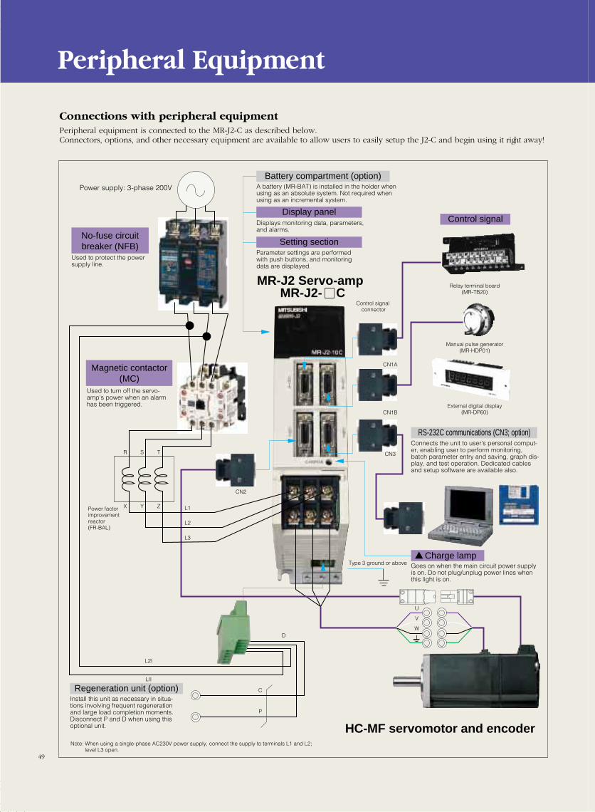
49
Connections with peripheral equipmentPeripheral equipment is connected to the MR-J2-C as described below.Connectors, options, and other necessary equipment are available to allow users to easily setup the J2-C and begin using it right away!
Peripheral Equipment
Used to protect the power supply line.
No-fuse circuit breaker (NFB)
Used to turn off the servo-amp's power when an alarm has been triggered.
Magnetic contactor (MC)
Power supply: 3-phase 200V
Battery compartment (option)
Display panel
Setting section
A battery (MR-BAT) is installed in the holder when using as an absolute system. Not required when using as an incremental system.
Regeneration unit (option)Install this unit as necessary in situa-tions involving frequent regeneration and large load completion moments. Disconnect P and D when using this optional unit.
RS-232C communications (CN3; option)Connects the unit to user's personal comput-er, enabling user to perform monitoring, batch parameter entry and saving, graph dis-play, and test operation. Dedicated cables and setup software are available also.
Charge lampGoes on when the main circuit power supply is on. Do not plug/unplug power lines when this light is on.
Displays monitoring data, parameters, and alarms.
Parameter settings are performed with push buttons, and monitoring data are displayed.
Type 3 ground or above
Control signal connector
HC-MF servomotor and encoder
MR-J2 Servo-ampMR-J2- C
CN2
CN1A
CN1B
CN3
C
P
D
L2I
L1
R S T
X Y Z
L2
L3
LII
U
V
W
Relay terminal board(MR-TB20)
Manual pulse generator(MR-HDP01)
External digital display(MR-DP60)
Power factorimprovement reactor(FR-BAL)
Control signal
Note: When using a single-phase AC230V power supply, connect the supply to terminals L1 and L2; level L3 open.
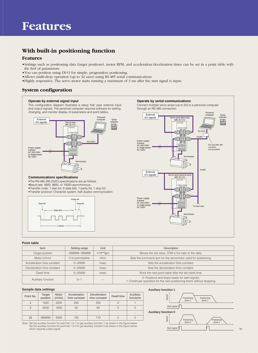
50
With built-in positioning functionFeatures•Settings such as positioning data (target positions), motor RPM, and acceleration/deceleration times can be set in a point table withthe feel of parameters.
•You can position using DI/O for simple, programless positioning.•Allows multi-drop operation (up to 32 axes) using RS-485 serial communications.•Highly responsive. The servo motor starts running a maximum of 3 ms after the start signal is input.
System configuration
Features
CN1A CN1B
CN2 CN3
CN1A CN1B
CN2 CN3
CN1A CN1B
CN2 CN3
Servo-ampMR-J2- C
RS485
RS485
RS-232C/RS-485 converter(not provided)
RS-232C
Operate by external signal inputThis configuration diagram illustrates a setup that uses external input and output signals. The personal computer requires software for setting, changing, and monitor display of parameters and point tables.
Communications specifications•The RS-485 (RS-232C) specifications are as follows.•Baud rate: 4800, 9600, or 19200 asynchronous.•Transfer code: 1 start bit, 8 data bits, 1 parity bit, 1 stop bit.•Transfer protocol: Character system, half-duplex communication.
Operate by serial communicationsConnect multiple servo amps (up to 32) to a personal computer through an RS-485 connection.
ExternalI/O signals
Personalcomputer
Power supply: 3-phase AC 200-230V or single-phase AC 230V
RS-232C
Servomotor
Start bit
Parity bit
Data bits
1 frame
Stop bit
Setupsoftware
ExternalI/O signals
ExternalI/O signals
Personalcomputer Setup
software
Power supply: 3-phase AC 200-230V or single-phase AC 230V
Power supply: 3-phase AC 200-230V or single-phase AC 230V
Servomotor
Servomotor
To next axis
Servo-amp (first axis)MR-J2- C
Servo-amp (second axis)MR-J2- C
Point table
Item
Target position
Motor (r/min)
Acceleration time constant
Deceleration time constant
Dwell time
Auxiliary function
Setting range
-999999~999999
0 to permissible
0~20000
0~20000
0~20000
0~1
Description
Moves the set value. STM is the ratio to the data.
Sets the command rpm for the servomotor used for positioning.
Sets the acceleration time constant.
Sets the deceleration time constant.
Runs the next point table after the set dwell time.
0: Positions and stops (waits for start signal).1: Continues operation for the next positioning block without stopping.
Unit
×10STMµm
r/min
msec
msec
msec
—
Sample data settings Auxiliary function 1
Auxiliary function 0
Point No.
1
2
:
15
Targetposition
1000
2000
:
999999
Accelerationtime constant
200
50
:
100
Motor(r/min)
2000
1600
:
3000
Decelerationtime constant
200
60
:
110
Auxiliaryfunctions
1
0
:
0
Dwell time
0
0
:
0
Note: Set the auxiliary function for point No.1 to 1 to get auxiliary function 1 as shown in the figure below. Set the auxiliary function for point No.1 to 0 to get auxiliary function 0 as shown in the figure below, which requires a start signal.
Spe
edS
peed
Start signal
Positioningblock 1
Positioningblock 1
Positioningblock 2
Positioningblock 2
Start signal
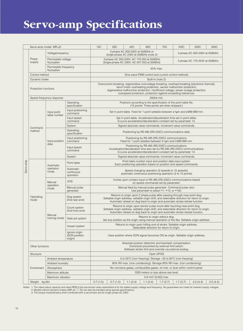
51
Servo-amp Specifications
Servo-amp model MR-J2- 10C 20C 40C 60C 70C 100C 200C 350C
Powersupply
Voltage/requency 3-phase AC 200-230V at 50/60Hz3-phase AC 200-230V at 50/60Hz orsingle-phase AC 230V at 50/60Hz (note 3)
Permissible voltagefluctuation 3-phase AC 170-253V at 50/60Hz3-phase AC 200-230V: AC 170-253 at 50/60Hz
Single-phase AC 230V: AC 207-253 at 50/60Hz
Permissible frequency fluctuation
Control method
Dynamic brake
Protection functions
Speed frequency response
Commandmethod
Operating mode
Other functions
Structure
Weight kg (lb) 0.7 (1.5) 1.1 (2.4) 1.1 (2.4) 1.7 (3.7) 1.7 (3.7) 2.0 (4.4) 2.0 (4.4)0.7 (1.5)
Environment
Ambient temperature
Ambient humidity
Atmosphere
Maximum altitude
Maximum vibration
Automatic operation mode
Manual operation mode
Manual homing mode
Input pointtable number
Input position data
Operatingspecification
Input positioning command
Input speed command
System
Operating specification
Input positioning command
Input speed command
System
Point table
Automatic continuous operation
JOG
Manual pulse generator
Dog system (find rear end)
Count system (find front end)
Data set system
Impact system
Ignore origin (SON position origin)
Sine wave PWM control and current control methods
Built-in (note 2)
Overcurrent breaking, regenerative overvoltage breaking, overload breaking (electronic thermal),servo motor overheating protection, sensor malfunction protection,
regenerative malfunction protection, insufficient voltage, power outage protection,overspeed protection, protection against exceeding tolerances.
250Hz min.
Positions according to the specification of the point table No.(15 points. Three points set when shipped.)
Set in point table. Feed for 1 point settable between ±1µm and ±999.999 mm.
Set in point table. Acceleration/deceleration time set in point table.S-curve acceleration/deceleration constant set by parameter 14.
Signed absolute value commands, increment value commands.
Positioning by RS-485 (RS-232C) communications data.
Positioning by RS-485 (RS-232C) communications.Feed for 1 point settable between ±1µm and ±999.999 mm.
Positioning by RS-485 (RS-232C) communications.Acceleration/deceleration time also set by RS-485 (RS-232C) communications.
S-curve acceleration/deceleration constant set by parameter 14.
Signed absolute value commands, increment value commands.
Point table number input and position data input system.Each positioning operation based on position and speed commands.
Speed changing operation (2 speeds to 15 speeds),automatic continuous positioning operation (2 to 15 points)
Inches upon contact input or RS-485 (RS-232C) communications basedon speed commands set by parameter.
Manual feed by manual pulse generator. Command pulse ratio:Use parameter to select ×1, ×10, or ×100.
Returns to origin upon Z phase pulse after passing through near-point dog.Settable origin address, settable origin shift, and selectable direction for return to origin.
Automatic retreat on dog back to origin and automatic stroke retreat function.
Returns to origin upon sensor pulse count after touching near-point dog.Settable origin address, settable origin shift, and selectable direction for return to origin.
Automatic retreat on dog back to origin and automatic stroke retreat function.
Returns to origin without dog.Set any position as the origin using manual operation or the like. Settable origin address.
Returns to origin upon hitting end of stroke. Settable origin address.Selectable direction for return to origin.
Uses position where SON signal becomes ON as origin. Settable origin address.
Absolute position detection and backlash compensation.Overtravel prevented by external limit switch.
Software stroke limit and override via external analog.
Open (IP00)
0 to 55°C (non freezing). Storage −20 to 65°C (non freezing)
90% RH max. (non condensing). Storage 90% RH max. (non condensing)
No corrosive gases, combustible gases, oil mist, or dust within control panel.
1000 meters or less above sea level.
5.9 m/s2 [0.6G] max.
±5% max.
Ser
vo-a
mp
Notes: 1. The rated output capacity and rated RPM of the servomotor when assembled is for the stated supply voltage and frequency. No guarantees are made for lowered supply voltages.2. Models without dynamic brakes (MR-J2-MMD) can also be handled using special specifications.3. The torque characteristics when combined with a servomotor are for single phase AC 230V.
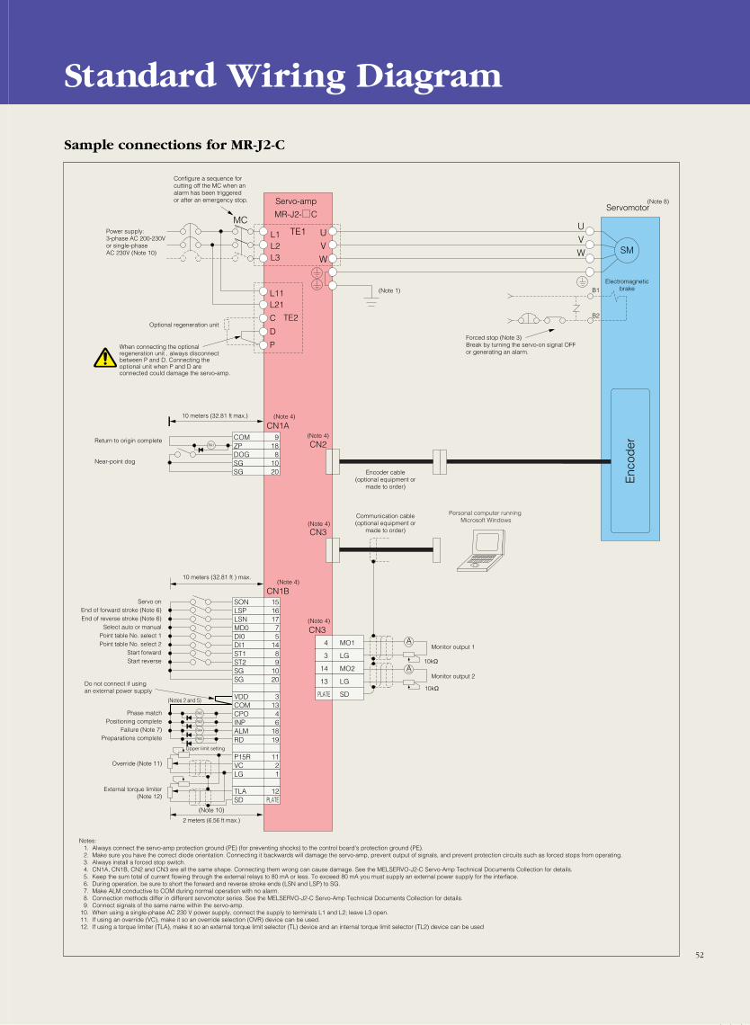
52
Standard Wiring Diagram
A
RA2
(Notes 2 and 5)
(Note 4)
(Note 10)
(Note 4)
(Note 4)
(Note 4)
(Note 4)
(Note 1)
RA3
RA4
CN1B
CN1A
CN3
CN3
CN2
Encoder cable(optional equipment or
made to order)
Forced stop (Note 3)Break by turning the servo-on signal OFFor generating an alarm.
Communication cable(optional equipment or
made to order)
SON 15
4 MO1
3 LG
14 MO2
13 LG
PLATE SD
LSP 16LSN 17MD0 7DI0 5DI1 14ST1 8ST2 9SG 10SG 20
VDD 3COM 13CPO 4INP 6ALM 18
P15R 11VC 2LG 1
TLA 12SD PLATE
RA1
SM
UVW
UVW
L1L2L3
L11L21
C
D
P
TE1MC
TE2
MR-J2- C
COM 9ZP 18DOG 8SG 10SG 20
A
B1
B2
10 meters (32.81 ft max.)
10kΩ
10kΩ
2 meters (6.56 ft max.)
10 meters (32.81 ft ) max.
Upper limit setting
Enc
oder
Servo-amp
RD 19RA5
Power supply: 3-phase AC 200-230V or single-phase AC 230V (Note 10)
When connecting the optional regeneration unit , always disconnect between P and D. Connecting the optional unit when P and D are connected could damage the servo-amp.
Configure a sequence for cutting off the MC when an alarm has been triggered or after an emergency stop.
Optional regeneration unit
Servomotor(Note 8)
Return to origin complete
Near-point dog
Servo onEnd of forward stroke (Note 6)End of reverse stroke (Note 6)
Select auto or manualPoint table No. select 1Point table No. select 2
Start forwardStart reverse
Phase matchPositioning complete
Failure (Note 7)Preparations complete
Override (Note 11)
External torque limiter(Note 12)
Do not connect if using an external power supply
Personal computer running Microsoft Windows
Monitor output 1
Monitor output 2
Notes:1. Always connect the servo-amp protection ground (PE) (for preventing shocks) to the control board's protection ground (PE).2. Make sure you have the correct diode orientation. Connecting it backwards will damage the servo-amp, prevent output of signals, and prevent protection circuits such as forced stops from operating.3. Always install a forced stop switch.4. CN1A, CN1B, CN2 and CN3 are all the same shape. Connecting them wrong can cause damage. See the MELSERVO-J2-C Servo-Amp Technical Documents Collection for details.5. Keep the sum total of current flowing through the external relays to 80 mA or less. To exceed 80 mA you must supply an external power supply for the interface.6. During operation, be sure to short the forward and reverse stroke ends (LSN and LSP) to SG.7. Make ALM conductive to COM during normal operation with no alarm.8. Connection methods differ in different servomotor series. See the MELSERVO-J2-C Servo-Amp Technical Documents Collection for details.9. Connect signals of the same name within the servo-amp.
10. When using a single-phase AC 230 V power supply, connect the supply to terminals L1 and L2; leave L3 open.11. If using an override (VC), make it so an override selection (OVR) device can be used.12. If using a torque limiter (TLA), make it so an external torque limit selector (TL) device and an internal torque limit selector (TL2) device can be used
Electromagneticbrake
Sample connections for MR-J2-C
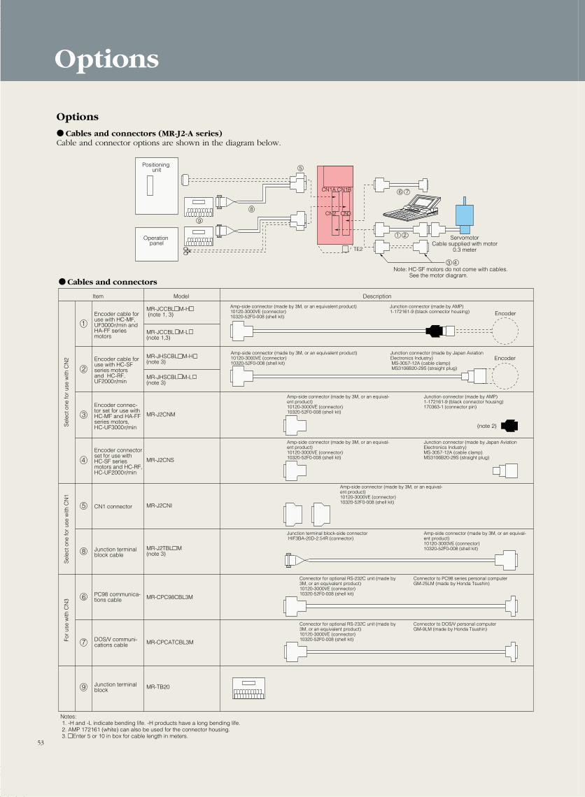
Options
Cables and connectors (MR-J2-A series)Cable and connector options are shown in the diagram below.
Options
1
2
3
4
5
8
6
7
9
CN1A CN1B
CN2 CN3
TE2
1
5
76
8
2
3 4
9
Positioning unit
Operation panel
ServomotorCable supplied with motor
0.3 meter
Note: HC-SF motors do not come with cables. See the motor diagram.
Cables and connectors
Item Model Description
Sel
ect o
ne fo
r us
e w
ith C
N2
Sel
ect o
ne fo
r us
e w
ith C
N1
For
use
with
CN
3
Encoder cable for use with HC-MF,UF3000r/min and HA-FF series motors
Encoder cable for use with HC-SFseries motors and HC-RF, UF2000r/min
Encoder connec-tor set for use with HC-MF and HA-FF series motors,HC-UF3000r/min
Encoder connector set for use with HC-SF series motors and HC-RF, HC-UF2000r/min
CN1 connector
Junction terminal block cable
PC98 communica-tions cable
DOS/V communi-cations cable
Junction terminal block
MR-JCCBL M-H (note 1, 3)
MR-JCCBL M-L (note 1,3)
MR-JHSCBL M-H (note 3)
MR-JHSCBL M-L (note 3)
MR-J2CNM
Amp-side connector (made by 3M, or an equivalent product)10120-3000VE (connector)10320-52F0-008 (shell kit)
Junction connector (made by AMP)1-172161-9 (black connector housing) Encoder
Amp-side connector (made by 3M, or an equivalent product)10120-3000VE (connector)10320-52F0-008 (shell kit)
Junction connector (made by Japan Aviation Electronics Industry) MS-3057-12A (cable clamp) MS3106B20-29S (straight plug)
Encoder
MR-J2CNS
MR-J2CNI
MR-J2TBL M(note 3)
MR-CPC98CBL3M
MR-CPCATCBL3M
MR-TB20
Amp-side connector (made by 3M, or an equival-ent product)10120-3000VE (connector)10320-52F0-008 (shell kit)
Junction connector (made by AMP)1-172161-9 (black connector housing)170363-1 (connector pin)
Amp-side connector (made by 3M, or an equival-ent product)10120-3000VE (connector)10320-52F0-008 (shell kit)
Junction connector (made by Japan Aviation Electronics Industry)MS-3057-12A (cable clamp)MS3106B20-29S (straight plug)
Junction terminal block-side connector HIF3BA-20D-2.54R (connector)
Amp-side connector (made by 3M, or an equival-ent product)10120-3000VE (connector)10320-52F0-008 (shell kit)
(note 2)
Amp-side connector (made by 3M, or an equival-ent product)10120-3000VE (connector)10320-52F0-008 (shell kit)
Connector for optional RS-232C unit (made by 3M, or an equivalent product)10120-3000VE (connector)10320-52F0-008 (shell kit)
Connector to PC98 series personal computerGM-25LM (made by Honda Tsushin)
Connector for optional RS-232C unit (made by 3M, or an equivalent product)10120-3000VE (connector)10320-52F0-008 (shell kit)
Connector to DOS/V personal computerGM-9LM (made by Honda Tsushin)
Notes: 1. -H and -L indicate bending life. -H products have a long bending life. 2. AMP 172161 (white) can also be used for the connector housing. 3. Enter 5 or 10 in box for cable length in meters.
53
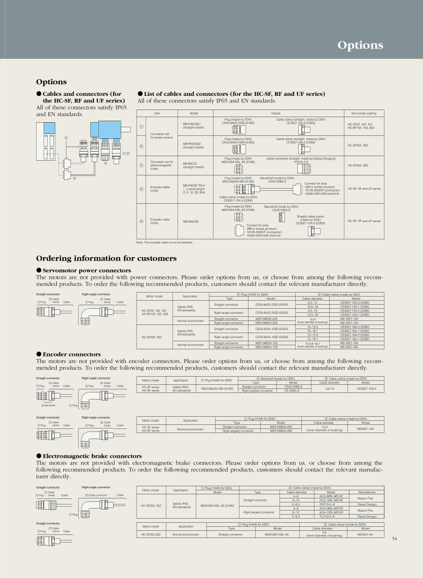
54
1
2
3
1
Item Model Details Servomotor pairing
Connector set for power source
Connector set for electromagnetic brake
MR-PWCNS1 (straight model)
MR-PWCNS2 (straight model)
MR-BKCN (straight model)
MR-ENCNS
Plug (made by DDK)CE05-6A22-23SD-B-BSS
Cable clamp (straight, made by DDK)CE3057-12A-2 (D265)
Plug (made by DDK)CE05-6A22-23SD-B-BSS
Cable clamp (straight, made by DDK)CE3057-12A-2 (D265)
Plug (made by DDK)MS3106A10SL-4S (D190)
Plug (made by DDK)MS3106A10SL-4S (D190)
Cable connector (straight, made by [Daiwa Dengyo])YOS10-5-8
Plug (made by DDK)MS3106A20-29S (D190)
Cable clamp (made by DDK)CE3057-12A-3 (D265)
Backshell (made by DDK)CE02-20BS-S
Backshell (made by DDK)CE02-20BS-S
Straight cable clamp(made by DDK)
CE3057-12A-3 (D265)
HC-SF52, 102, 152HC-RF103, 153, 203
HC-SF202, 352
HC-SF202, 352
4Encoder cable(note)
MR-ENCBMM-HM=cable length:2, 5, 10, 20, 30m
HC-SF, RF and UF series
5Encoder cable(note)
HC-SF, RF and UF series
Connect for amp(3M or similar product)10120-3000VF (connector)10320-52F0-008 (shell kit)
Connect for amp(3M or similar product)10120-3000VF (connector)10320-52F0-008 (shell kit)
Note: The encoder cable is not oil-resistant.
12
Right-angle connectorStraight connector
Plug Cable CableCable clamp
12
Straight connector
Plug CableCable clamp
13
Straight connector
Plug
2 Backshell
CableCable clamp
12
PlugCableclamp
12
Right-angle connectorStraight connector
Plug Cable CableCable clamp 1
2
PlugCableclamp
12
Right-angle connector
Straight connector
Plug Cable
Cable
Cable clamp
23
PlugCableclamp
1 Plug
Right-angle connector
Cable2 Cable connector
1 Plug
Plug (made by DDK) 2 Cable clamp (made by DDK)
HC-SF52, 102, 152HC-RF103, 153, 203
Satisfy IP65,EN standards
Normal environment
Satisfy IP65,EN standards
Normal environment
HC-SF202, 352
Motor model ApplicationType Model Model
CE3057-12A-2 (D265)CE3057-12A-1 (D265)CE3057-12A-2 (D265)CE3057-12A-1 (D265)MS-3057-12AMS-3057-12ACE3057-16A-2 (D265)CE3057-16A-1 (D265)CE3057-16A-2 (D265)CE3057-16A-1 (D265)MS-3057-16AMS-3057-16A
CE05-6A22-23SD-B-BSS
CE05-6A22-23SD-B-BSS
Straight connector
Right-angle connector
CE05-8A24-10SD-B-BAS
CE05-8A24-10SD-B-BAS
Straight connector
Right-angle connector
MS3106B22-23SMS3108B22-23S
Straight connectorRight-angle connector
MS3106B24-10SMS3108B24-10S
Straight connectorRight-angle connector
Cable diameter9.5~1312.5~169.5~1312.5~16
15.9(Inner diameter of bushing)
13~15.515~19.113~15.515~19.1
15.9 & 19.1(Inner diameter of bushing)
1 2
3
4
5CN1A CN1B
CN2 CN3
1 Plug (made by DDK)
1 Plug (made by DDK)
3 Cable clamp (made by DDK)
2 Cable clamp (made by DDK)
2 Backshell (made by DDK)
HC-SF seriesHC-RF series
Satisfy IP65,EN standards
HC-SF202, 352 MS3106A10SL-4S (D190)Satisfy IP65,EN standards
5.6(Inner diameter of bushing)
MS3106A20-29S (D190)
Motor model Application
Motor model Application
Motor model
HC-SF202,352 Normal environment Straight connector MS3106A10SL-4S MS3057-4A
Application
Type Model
Model Type
Model ModelCable diameterType
Cable diameter4~88~125~8.34~88~125~8.3
ACS-08RL-MS10FACS-12RL-MS10FYSO10-5~8ACA-08RL-MS10FACA-12RL-MS10FYLO10-5~8
Nippon Flex
Daiwa Dengyo
Nippon Flex
Daiwa Dengyo
Model Manufacturer
Cable diameter Model
6.8-10 CE3057-12A-3Straight connectorRight-angled connector
Straight connecto
Right-angled connector
CE02-20BS-SCE-20BA-S
2 Cable clamp (made by DDK)1 Plug (made by DDK)
HC-SF seriesHC-RF series Normal environment
Motor model ApplicationType Model Cable diameter Model
15.9(Inner diameter of bushing) MS3057-12A
Straight connectorRight-angled connector
MS3106B20-29SMS3108B20-29S
1 Plug (made by DDK) 2 Cable clamp (made by DDK)
Options
Cables and connectors (forthe HC-SF, RF and UF series)
All of these connectors satisfy IP65and EN standards.
Ordering information for customers
Servomotor power connectorsThe motors are not provided with power connectors. Please order options from us, or choose from among the following recom-mended products. To order the following recommended products, customers should contact the relevant manufacturer directly.
Encoder connectorsThe motors are not provided with encoder connectors. Please order options from us, or choose from among the following recom-mended products. To order the following recommended products, customers should contact the relevant manufacturer directly.
Electromagnetic brake connectorsThe motors are not provided with electromagnetic brake connectors. Please order options from us, or choose from among thefollowing recommended products. To order the following recommended products, customers should contact the relevant manufac-turer directly.
List of cables and connectors (for the HC-SF, RF and UF series)All of these connectors satisfy IP65 and EN standards.
Options
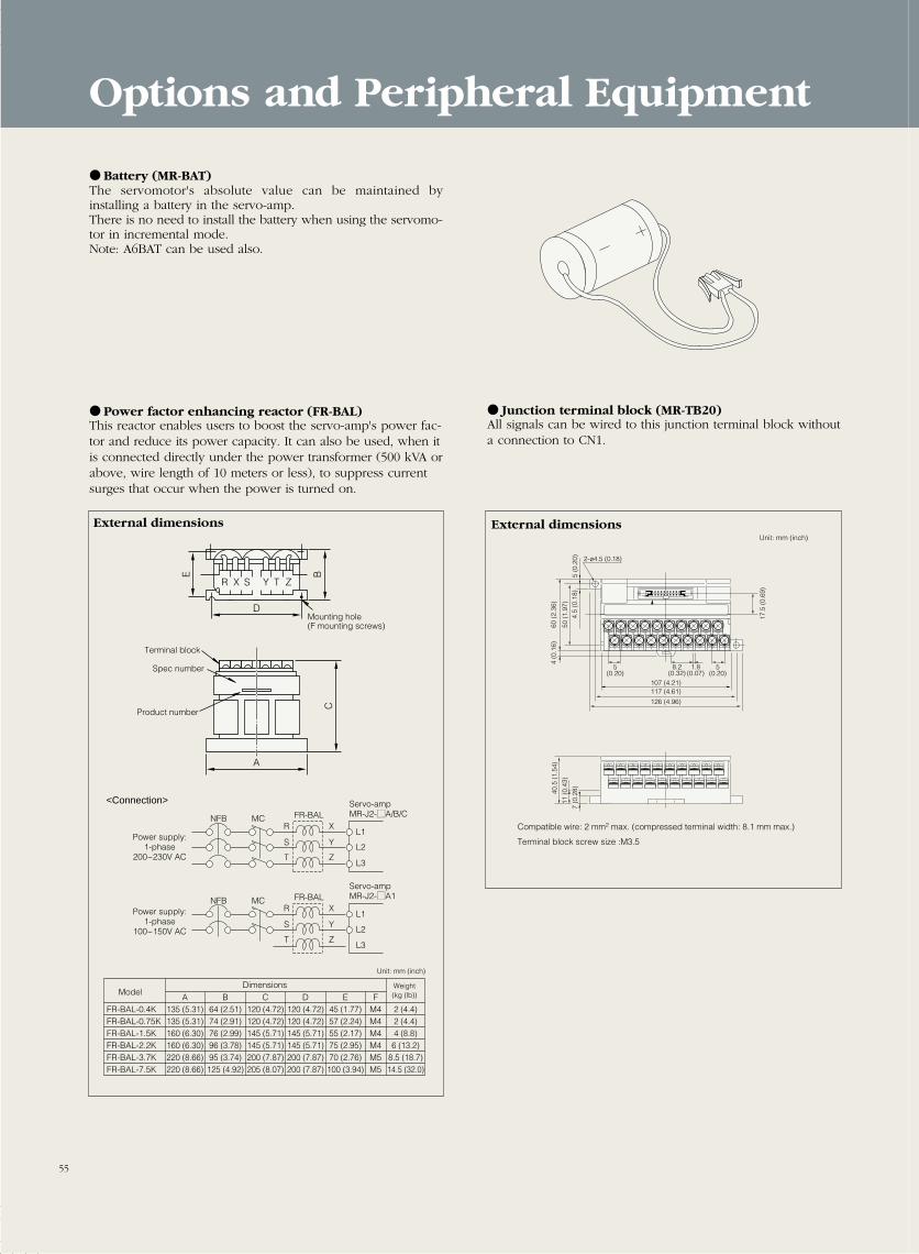
Battery (MR-BAT)The servomotor's absolute value can be maintained byinstalling a battery in the servo-amp.There is no need to install the battery when using the servomo-tor in incremental mode.Note: A6BAT can be used also.
Power factor enhancing reactor (FR-BAL)This reactor enables users to boost the servo-amp's power fac-tor and reduce its power capacity. It can also be used, when itis connected directly under the power transformer (500 kVA orabove, wire length of 10 meters or less), to suppress currentsurges that occur when the power is turned on.
Junction terminal block (MR-TB20)All signals can be wired to this junction terminal block withouta connection to CN1.
R X S ZTY
D
E BC
A
A135 (5.31)135 (5.31)160 (6.30)160 (6.30)220 (8.66)220 (8.66)
FR-BAL-0.4KFR-BAL-0.75KFR-BAL-1.5KFR-BAL-2.2KFR-BAL-3.7KFR-BAL-7.5K
B64 (2.51)74 (2.91)76 (2.99)96 (3.78)95 (3.74)
125 (4.92)
C120 (4.72)120 (4.72)145 (5.71)145 (5.71)200 (7.87)205 (8.07)
D120 (4.72)120 (4.72)145 (5.71)145 (5.71)200 (7.87)200 (7.87)
E45 (1.77)57 (2.24)55 (2.17)75 (2.95)70 (2.76)100 (3.94)
FM4M4M4M4M5M5
2 (4.4)2 (4.4)4 (8.8)6 (13.2)
8.5 (18.7)14.5 (32.0)
Mounting hole (F mounting screws)
Terminal block
Spec number
Product number
ModelDimensions Weight
(kg (lb))
Unit: mm (inch)
<Connection>
Power supply:1-phase
200~230V AC
Power supply:1-phase
100~150V AC
NFB MCR
S
T
X
Y
Z
L1
L2
L3
FR-BALServo-ampMR-J2-MA/B/C
NFB MCR
S
T
X
Y
Z
L1
L2
L3
FR-BALServo-ampMR-J2-MA1
External dimensions
10 11 12 13 14 15 16 17 18 19
0 1 2 3 4 5 6 7 8 9
107 (4.21)
60 (
2.36
)4
(0.1
6)
50 (
1.97
)4.
5 (0
.18)
5 (0
.20)
117 (4.61)
126 (4.96)
17.5
(0.
69)
5(0.20)
5(0.20)
1.8(0.07)
8.2(0.32)
2-ø4.5 (0.18)40
.5 (
1.54
)
11 (
0.43
)
7 (0
.28)
Compatible wire: 2 mm2 max. (compressed terminal width: 8.1 mm max.)
Unit: mm (inch)
Terminal block screw size :M3.5
External dimensions
Options and Peripheral Equipment
55
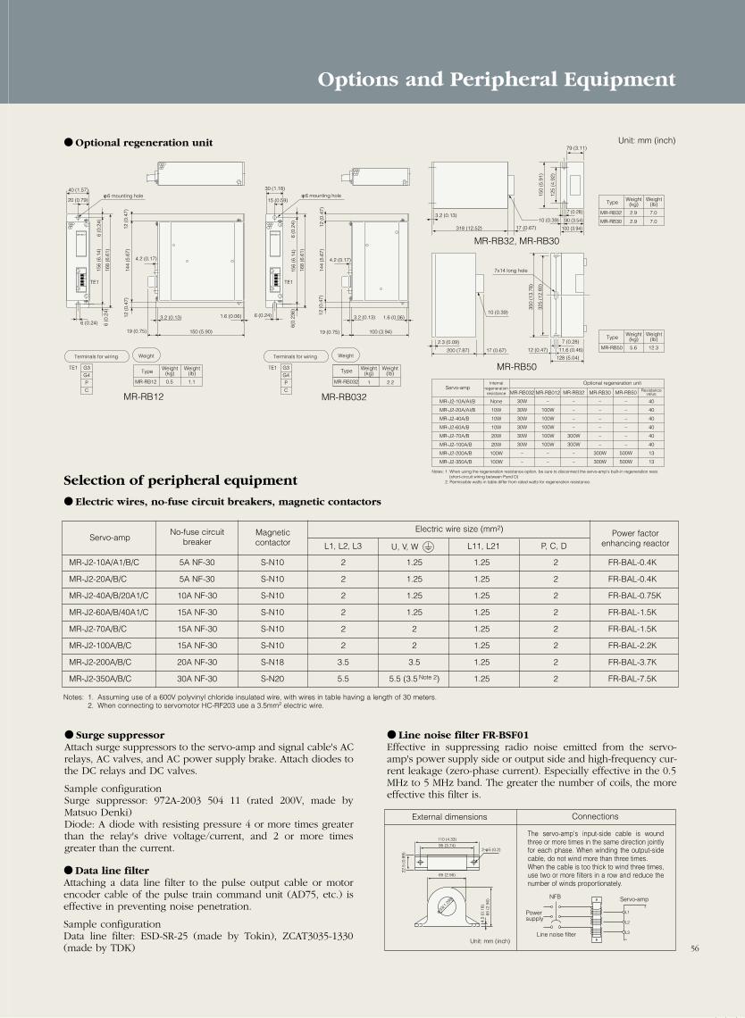
Surge suppressorAttach surge suppressors to the servo-amp and signal cable's ACrelays, AC valves, and AC power supply brake. Attach diodes tothe DC relays and DC valves.
Sample configurationSurge suppressor: 972A-2003 504 11 (rated 200V, made byMatsuo Denki)Diode: A diode with resisting pressure 4 or more times greaterthan the relay's drive voltage/current, and 2 or more timesgreater than the current.
Optional regeneration unit
MR-RB12
6 (0.24) 6 (0
.24)
6 (0
.24)
12 (
0.47
)12
(0.
47)
156
(6.1
4)
168
(6.6
1)
144
(5.6
7)
TE1
4.2 (0.17)
40 (1.57)
150 (5.90)
φ 6 mounting hole φ 6 mounting hole
19 (0.75)
3.2 (0.13) 1.6 (0.06)
20 (0.79)
12 (
0.47
)12
(0.
47)
144
(5.6
7)
4.2 (0.17)
100 (3.94)
2.3 (0.09) 7 (0.28)
11.6 (0.46)12 (0.47)
128 (5.04)
17 (0.67)200 (7.87)
19 (0.75)
3.2 (0.13) 1.6 (0.06)
G3
G4
P
C
MR-RB12
6 (0.24)
6(0.
236)
6 (0
.24)
156
(6.1
4)
168
(6.6
1)
TE1
30 (1.18)
15 (0.59)
G3
G4
P
C
MR-RB32, MR-RB30
MR-RB50
318 (12.52) 17 (0.67)
3.2 (0.13)
100 (3.94)
90 (3.54)
79 (3.11)
10 (0.39)
10 (0.39)
7 (0.28)
150
(5.9
1)
125
(4.9
2)
325
(12.
80)
350
(13.
78)
7x14 long hole
MR-RB032
30W
30W
30W
30W
30W
30W
–
–
None
10W
10W
10W
20W
20W
100W
100W
MR-J2-10A/AI/B
MR-J2-20A/AI/B
MR-J2-40A/B
MR-J2-60A/B
MR-J2-70A/B
MR-J2-100A/B
MR-J2-200A/B
MR-J2-350A/B
MR-RB012
–
100W
100W
100W
100W
100W
–
–
MR-RB30
–
–
–
–
–
–
300W
300W
MR-RB50
–
–
–
–
–
–
500W
500W
MR-RB32
–
–
–
–
300W
300W
–
–
40
40
40
40
40
40
13
13
Servo-ampInternal
regenerationresistance
MR-RB12 1.10.5
G3
G4
P
C
TE1
Terminals for wiring Weight
MR-RB032
G3
G4
P
C
TE1
Terminals for wiring
MR-RB032MR-RB12
Weight
Weight(kg)
Weight(lb)
Weight(kg)
Weight(lb)Type Type
1 2.2 Optional regeneration unitResistance
value
Notes: 1. When using the regeneration resistance option, be sure to disconnect the servo-amp's built-in regeneration resis (short-circuit wiring between Pand D) 2. Permissible watts in table differ from rated watts for regeneration resistance.
MR-RB32 7.02.9
MR-RB30 7.02.9
Weight(kg)
Weight(lb)Type
MR-RB50 12.35.6
Weight(kg)
Weight(lb)Type
Notes: 1. Assuming use of a 600V polyvinyl chloride insulated wire, with wires in table having a length of 30 meters.2. When connecting to servomotor HC-RF203 use a 3.5mm2 electric wire.
No-fuse circuit breaker
Electric wire size (mm2)MagneticcontactorServo-amp Power factor
enhancing reactorL1, L2, L3 U, V, W L11, L21 P, C, D
MR-J2-10A/A1/B/C 5A NF-30 S-N10 2 1.25 1.25 2 FR-BAL-0.4K
MR-J2-20A/B/C 5A NF-30 S-N10 2 1.25 1.25 2 FR-BAL-0.4K
MR-J2-40A/B/20A1/C 10A NF-30 S-N10 2 1.25 1.25 2 FR-BAL-0.75K
MR-J2-60A/B/40A1/C 15A NF-30 S-N10 2 1.25 1.25 2 FR-BAL-1.5K
MR-J2-70A/B/C 15A NF-30 S-N10 2 2 1.25 2 FR-BAL-1.5K
MR-J2-100A/B/C 15A NF-30 S-N10 2 2 1.25 2 FR-BAL-2.2K
MR-J2-200A/B/C 20A NF-30 S-N18 3.5 3.5 1.25 2 FR-BAL-3.7K
MR-J2-350A/B/C 30A NF-30 S-N20 5.5 5.5 (3.5 Note 2) 1.25 2 FR-BAL-7.5K
Selection of peripheral equipment
Electric wires, no-fuse circuit breakers, magnetic contactors
Line noise filter FR-BSF01Effective in suppressing radio noise emitted from the servo-amp's power supply side or output side and high-frequency cur-rent leakage (zero-phase current). Especially effective in the 0.5MHz to 5 MHz band. The greater the number of coils, the moreeffective this filter is.
Data line filterAttaching a data line filter to the pulse output cable or motorencoder cable of the pulse train command unit (AD75, etc.) iseffective in preventing noise penetration.
Sample configurationData line filter: ESD-SR-25 (made by Tokin), ZCAT3035-1330(made by TDK)
φ 33(
1.299
)
65 (2.56)
95 (3.74)110 (4.33)
65 (
2.56
)4.
5 (0
.18)
22.5
(0.
89)
2-φ 5 (0.2)
L1
Servo-amp
Line noise filterUnit: mm (inch)
Powersupply
NFB
L2
L3
External dimensions Connections
The servo-amp's input-side cable is woundthree or more times in the same direction jointlyfor each phase. When winding the output-sidecable, do not wind more than three times.When the cable is too thick to wind three times,use two or more filters in a row and reduce thenumber of winds proportionately.
56
Options and Peripheral Equipment
Unit: mm (inch)

AX1
AX2
AX3
A 1SD75P3
A ISO75P3
RS-422
MODE
AX1
AX2 AX3A1SD75P3
MODE
AX1
AX2 AX3
RS-422
AX1AX2AX3
111 (4.37)
Print board
Print board
4.2 (0.17)
250
(9.8
4)
108 (4.25)4.2 (0.17)
3 (0.12) 37.5 (1.48)
2 (0
.08)
130
(5.1
2)
34.5 (1.36)93.6 (3.67)
2.3 (0.09)6.5 (0.26)
Command Unit
The following positioning controllers are available for the MR-J2-A series servo-amps. Choose the unit that best fits your operatingobjectives and system size.
Name Specification/application overview External dimensions
All of the units have been made more compact: 1 slot for 1 to 3 axes. And theyare compatible with the A and QnA series PLC's.A high-precision, highly functional positioning unit that uses a 32-bit RISCchip.
Model AD75P1 AD75P2 AD75P3Item A1SD75P1 A1SD75P2 A1SD75P3
Number of control axes 12 simultaneous 3 simultaneous2 independent 3 independent
Interpolation functions None2-axes linear interpolation 2-axes linear interpolation
2-axes circular interpolation 2-axes circular interpolation
Control mode PTP control, locus control, speed control, speed position control
Command mode Incremental, absolute
Maximum number of output pulses ±2147483648
Maximum pulse frequency Differential output: 400 kpps, open collector: 200 kpps
Positioning pattern 600 patterns/shaft (100 patterns from ladder)
Input/output duty points 32
Acceleration/deceleration patterns 4, automatic trapezoid, S-acceleration/deceleration
MELSEC-F series-com-patible 2-axis position-ing units
FX-20GME-20GM
Users can choose either the FX-20GM alone or coupled with an FX PLC. Thisunits offer a broad range of uses, from interpolation operation to high-fre-quency feed operation.
FX-20GM/E-20GM 2-axispositioning unit
Model FX-20GM / E-20GMItem (language-equipped model)
Number of control axes 2 simultaneous, 2 independent
Interpolation functions Linear interpolation, circular interpolation
Compatible PLC Stand-alone use
Command mode Incremental, absolute
Absolute position encoder Can be used with MR-H model servo with ABS function
Maximum number of output pulses C ±2,147,483,648
Maximum pulse frequency Open collector: 200 kpps, during interpolation operation: 100 kpps
Program memory Built-in 7.8 k step RAM
ModelFX-1PG / FX-1GM
Item
Number of control axes 1
Compatible sequencer Stand-alone use, FX2/FX2C FX2/FX2C series
Command mode Incremental, absolute
Maximum number of output pulses ±2,147,483,648
Maximum pulse frequency Open collector: 100 kpps
Program memory Communication with PLC
MELSEC-F series-com-patible 1-axis position-ing units
FX-1PGFX-1GM
The FX-1PG can be expanded for up to 8 axis, is available as FX-sequencerspecial-unit blocks. The units can be used for simple positioning applica-tions.
FX-1PG 1-axis pulse output block
FX-20GM
E-20GM
AD75P A1SD75P
MELSEC-A, MELSEC-QnA series compatible
AD75PA1SD75P
POWER
READY-x
READFY-y
ENTER-x
ENTER-y
BATTY-v
CPU-E
A B C D E F G H
A B C D E F G H
V0 V1 V2 V3 V4 V5 V6 V7
X0 X1 X3 X4 X5 X6 X7 X8
x
y
I J K L M N SUB
I J K L M Nx
y
MENUPOWER
MELSERV0 FX-20GM
MITSUBISHI
100 (3.94)110 (4.33)
125
(4.9
2)14
0 (5
.51)
95 (3.74)10 (0.39)M35 Screw
4-φ5.5 (0.22)mountingholes
35mm (1.38) width DIN rail mountinggroove
95(3.74)10 (0.39)
140
(5.5
1)12
5 (4
.92)
45(1.77)
35(1.38)
2-φ5.5
FX-1PG
STOPDOGPRO
FPRPCLRENR
35mm (1.38)width DIN rail mountinggroove
AD75P positioning unit
A1SD75P positioning unit
Unit: mm (inch)
Unit: mm (inch)
FX-1PG1-axis pulse output block
FX-1GMpulse output block unit
FX-1GM 1-axis positionning units
POWER
READY
ENTER-xENTER-x
CPU-E
MELSERV0 FX-1GM
MITSUBISHI
A E I X0
B F J X1
C G K X2
D H L X3
Y1
Y2
Y3
Y4
T4
T5
T6
M
O
P
NL A B C D F H J L X1 X3SG COM1 COM2 COM3 E G I K X0 X2
5V-5V+ 2 MO Y1 Y3 Y5COM5COM5 COM7MO5V-5V+ VC M N O COM6 Y0 Y2 Y4 PO Y
150 (5.90)160 (6.30) 95 (3.74)
10 (0.39)
125
(4.9
2)
140
(5.5
1)
M3.5 terminal Screw 4-φ5.5 (0.22) mounting holes
35mm (1.38)width DIN rail mountinggroove
57
Unit: mm (inch)

58
Name Specification/application overview External dimensions
The following servo-system controllers (SSC) are available for the MR-J2-B series servo-amps. Choose the unit that best fits your oper-ating objectives and system size.
A171SH/A172SHMotion controller
Combination of a servo-controller with the MELSEC-A high-perfor-mance all-purpose PLC allows motion and sequence control with onesingle controller. This previously required two separate controllers.Four software packages are available for different applications.
Conveyor and assembly software (SV13)Automated unit software (SV22, CAMP)Machine tool peripheral software (SV43)Dedicated robot software (SV51)
ModelA171SH A172SH A273UHItem
Number of control axis 4 8 32
Interpolation functions Linear interpolation (max. 4-axes) / Circular interpolation (2-axes)
PTP control, speed control, synchronous control,Control mode fixed distance feed speed & position control,
CP control, speed switch control
Acceleration/deceleration Automatic trapezoid, S-acceleration / decelerationpattern
Maximum inputs & outputs 512 1024 2048
Servo-amp External External (max. 22kW)Internal (max. 600W)
A273UH Motion controller
Command Unit
220 (8.66)
4-mounting screws
Basic base
Basic base
4-φ6 (0.24) mounting holes(M5 mounting screws)
(M5×25)
200 (7.87)
130
(5.1
2)4.
1 (0
.16)
110
(4.3
3)
480 (18.90)460 (18.11)
110 (4.33)93.6 (3.69) 16.4 (0.65)
145 (5.71)106 (4.17) 9
(0.35)30
(1.18)
200
(7.8
7)25
0 (8
.66)
160
(6.3
0)
Unit: mm (inch)
AX1
AX2
AX3
A 1SD75P3
A ISO75P3
RS-422
MODE
AX1
AX2 AX3A1SD75P3
MODE
AX1
AX2 AX3
RS-422
AX1AX2AX3
111 (4.37)
Print board
Print board
4.2 (0.17)
250
(9.8
4)
108 (4.25)4.2 (0.17)
3 (0.12) 37.5 (1.48)
2 (0
.08)
130
(5.1
2)
34.5 (1.36)93.6 (3.67)
2.3 (0.09)6.5 (0.26)
All of the units have been made more compact: 1 slot for 1 to 3 axes. And theyare compatible with the A and QnA series PLC's.A high-precision, highly functional positioning unit that uses a 32-bit RISCchip.
AD75M A1SD75M
AD75MA1SD75M
AD75M positioning unit
A1SD75M positioning unit
Unit: mm (inch)
Model AD75M1 AD75M2 AD75M3Item A1SD75M1 A1SD75M2 A1SD75M3
Number of control axes 12 simultaneous 3 simultaneous2 independent 3 independent
Interpolation functions None2-axes linear interpolation 2-axes linear interpolation
2-axes circular interpolation 2-axes circular interpolation
Control mode PTP control, locus control, speed control, speed position control
Command mode Incremental, absolute
Maximum number of output pulses ±2147483648
Positioning pattern 600 patterns/shaft (100 patterns from ladder)
Input/output duty points 32
Acceleration/deceleration patterns 4, automatic trapezoid, S-acceleration/deceleration

59
Using Personal Computers
Capacity selection softwareMRZJW3-MOTSZMM
A user-friendly design facilitates selection of the optimumservo-amp, servomotor (including brake and decelerator), andoptional regenerative devices when you enter constants intomachine-specific screens.
Features
(1) Windows 3.1 and Windows 95 (note 1) CompatibleWorks on computers running Windows 3.1 or Windows95. Requires at least 4 MB of memory and 1 MB of harddisk space.
(2) Provides numerous structural options. Handles ballscrews, rack and pinions, roll feeds, rotating tables, dol-lies, elevators, conveyors, and other (direct inertial input)devices.
(3) Easy to convert units. It’s easy to calculate and convert inSI, MKS mass, and inch/pound units.
Specifications
Parameter Description
Types of structural machine elements Nine types: Horizontal ball screws, vertical ball screws, rack and pinions, roll feeds, rotating tables, dollies,elevators, conveyors, and other (direct inertial input) devices.
Selected servo-amp name, selected servomotor name, selected regenerative resistor name,Parameters load inertial moment, load inertial moment ratio, peak torque ratio, effective torque, effective torque ratio,
Output of results regenerative power, and regenerative power ratio.
Printing Prints the input parameters, calculation process, and selected results.
Data storage Gives the input parameters a file name and saves them to a floppy.
Inertial moment calculation function Five types: centrifugal cylinder, off-axis square shaft, linear motion, hanging, and decelerator.
Notes:1. Windows is a registered trademark of the Microsoft Corporation.2. This software may not run correctly on all personal computers.3. The MRZJW3-MOTSZ41 capacity selection software does not work for MR-J2-C. It will after the next upgrade. Version 41 will work with HC-MF, HA-FF, HC-SF, UF 2000 r/min,
and HC-RF series motors.
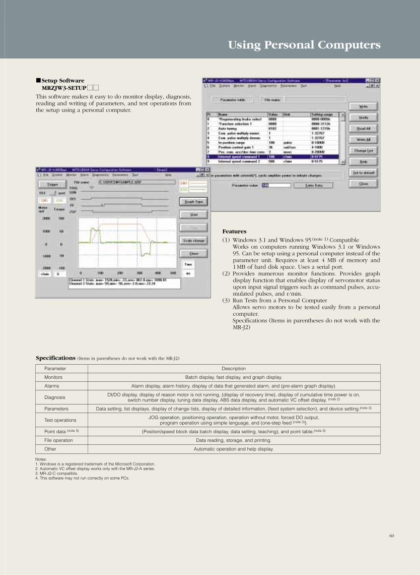
60
Using Personal Computers
Setup SoftwareMRZJW3-SETUPMM
This software makes it easy to do monitor display, diagnosis,reading and writing of parameters, and test operations fromthe setup using a personal computer.
Features
(1) Windows 3.1 and Windows 95 (note 1) CompatibleWorks on computers running Windows 3.1 or Windows95. Can be setup using a personal computer instead of theparameter unit. Requires at least 4 MB of memory and1MB of hard disk space. Uses a serial port.
(2) Provides numerous monitor functions. Provides graphdisplay function that enables display of servomotor statusupon input signal triggers such as command pulses, accu-mulated pulses, and r/min.
(3) Run Tests from a Personal ComputerAllows servo motors to be tested easily from a personalcomputer.Specifications (Items in parentheses do not work with theMR-J2)
Specifications (Items in parentheses do not work with the MR-J2)
Parameter Description
Monitors Batch display, fast display, and graph display.
Alarms Alarm display, alarm history, display of data that generated alarm, and (pre-alarm graph display).
Diagnosis DI/DO display, display of reason motor is not running, (display of recovery time), display of cumulative time power is on,switch number display, tuning data display, ABS data display, and automatic VC offset display. (note 2)
Parameters Data setting, list displays, display of change lists, display of detailed information, (feed system selection), and device setting.(note 3)
Test operations JOG operation, positioning operation, operation without motor, forced DO output,program operation using simple language, and (one-step feed (note 3)).
Point data (note 3) (Position/speed block data batch display, data setting, teaching), and point table.(note 3)
File operation Data reading, storage, and printing.
Other Automatic operation and help display.
Notes:1. Windows is a registered trademark of the Microsoft Corporation.2. Automatic VC offset display works only with the MR-J2-A series.3. MR-J2-C compatible.4. This software may not run correctly on some PCs.
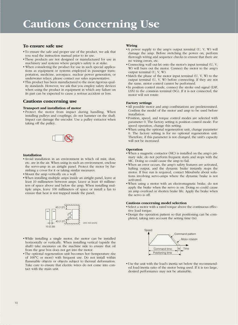
Wiring•A power supply to the amp’s output terminal (U, V, W) willdamage the amp. Before switching the power on, performthorough wiring and sequence checks to ensure that there areno wiring errors, etc.
• Connecting wall out-let onto the motor's input terminal (U, V,W) will burn out the motor. Connect the motor to the amp’soutput terminal (U, V, W).
• Match the phase of the motor input terminal (U, V, W) to theoutput terminal (U, V, W) before connecting. If they are notthe same, motor control cannot be performed.
• In position control mode, connect the stroke end signal (LSP,LSN) to the common terminal (SG). If it is not connected, themotor will not rotate.
Factory settings• All possible motor and amp combinations are predetermined.Confirm the model of the motor and amp to be used beforeinstallation.
• Position, speed, and torque control modes are selected withparameter 0. The factory setting is position control mode. Forspeed operation, change this setting.
• When using the optional regeneration unit, change parameter0. The factory setting is for no optional regeneration unit.Therefore, if this parameter is not changed, the unit's capacitywill not be increased.
Operation• When a magnetic contactor (MC) is installed on the amp’s pri-mary side, do not perform frequent starts and stops with theMC. Doing so could cause the amp to fail.
• When an error occurs, the amp's safety features are activated,halting output, and the dynamic brake instantly stops themotor. If free run is required, contact Mitsubishi about solu-tions involving servo-amps where the dynamic brake is notactivated.
• When using a motor with an electromagnetic brake, do notapply the brake when the servo is on. Doing so could causean amp overload or shorten brake life. Apply the brake whenthe servo is off.
Cautions concerning model selection• Select a motor with a rated torque above the continuous effec-tive load torque.
• Design the operation pattern so that positioning can be com-pleted, taking into account the setting time (ts).
• Use the unit with the load’s inertia set below the recommend-ed load/inertia ratio of the motor being used. If it is too large,desired performance may not be attainable.
To ensure safe use• To ensure the safe and proper use of the product, we ask thatyou read the instruction manual prior to its use.
• These products are not designed or manufactured for use inmachinery and systems where people’s safety is at stake.
• When considering the product for use in such special applica-tions as equipment or systems employed in passenger trans-portation, medicine, aerospace, nuclear power generation, orunderwater relays, please contact our sales representative.
• This product has been manufactured to the most rigorous qual-ity standards. However, we ask that you employ safety deviceswhen using the product in equipment in which any failure onits part can be expected to cause a serious accident or loss.
Cautions concerning use
Transport and installation of motor• Protect the motor from impact during handling. Wheninstalling pulleys and couplings, do not hammer on the shaft.Impact can damage the encoder. Use a pulley extractor whentaking off the pulley.
Installation• Avoid installation in an environment in which oil mist, dust,etc. are in the air. When using in such an environment, enclosethe servo-amp in an airtight panel. Protect the motor by fur-nishing a cover for it or taking similar measures.
• Mount the amp vertically on a wall.• When installing multiple amps inside an airtight panel, leave atleast 10 millimeters between amps. Leave at least 40 millime-ters of space above and below the amp. When installing mul-tiple amps, leave 100 millimeters of space or install a fan toensure that heat is not trapped inside the panel.
• While installing a single motor, the motor can be installed horizontally or vertically. When installing vertical (upside theshaft) take measures on the machine side to ensure that oilfrom the gear box does not get into the motor.
• The optional regeneration unit becomes hot (temperature riseof 100°C or more) with frequent use. Do not install withinflammable objects or objects subject to thermal deformation.Take care to ensure that electric wires do not come into con-tact with the main unit.
Cautions Concerning Use
40 (1.57)
40 (1.57)Unit: mm (inch)
10 (0.39)
61
SpeedCommand pattern
Command timePositioning time
Motor rotation
Timets
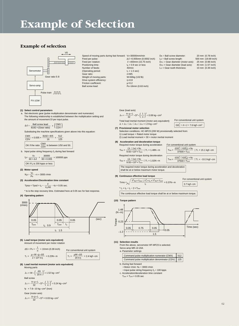
Example of Selection
62
Example of selectionV0
0.05 0.05 0.05
TpsdTpsa tsto 0.9
tf 1.5
3000(r/min)
(sec)
1.48(N • m)
0.23
–1.2
0.05 0.75 0.05
1.5
0.05Time (sec)
Servomotor
Gear ratio 5:8
Speed of moving parts during fast forward: V0=30000mm/min DB = Ball screw diameter: 20 mm (0.78 inch)Feed per pulse: ∆R=0.005mm (0.0002 inch) LB = Ball screw length: 500 mm (19.69 inch)Feed per rotation: R=400mm (15.75 inch) DG1 = Gear diameter (motor axis): 25 mm (0.98 inch)Positioning time: t0 = 0.9 sec or less DG2 = Gear diameter (load axis): 40 mm (1.57 inch)Number of feeds: 40/min LG = Gear tooth thickness: 10 mm (0.39 inch)(Operating period: t1 = 1.5 sec)Gear ratio: n=8/5 Weight of moving parts: W=60kg (132 lb) Drive system efficiency: η=0.8Friction coefficient: µ=0.2Ball screw lead: PB=16mm (0.63 inch)
(1) Select control parametersa. Set electronic gear (pulse multiplication denominator and numerator)
The following relationship is established between the multiplication setting and the amount of movement Dl per input pulse.
Substituting the machine specifications given above into this equation:
OK if the ratio is between 1/50 and 50.
b. Input pulse string frequency f0 during fast forward
OK if f0 is 200 kpps or less
(2) Motor speed
(3) Acceleration/Deceleration time constant
* ts is the stop recovery time. Estimated here at 0.05 sec for fast response.
(4) Operating pattern
Pulse train
Servo-amp
FX-1GM
∆R= CMXBall screw lead8192 × (Gear ratio) CDV
CMXCDV
512125
8192 × 8/516
× ( )
= 0.005 × =
V0
60 × ∆R30000
60 × 0.005=f0=
V0
PB• n = 3000 r/minN0=
= 100000 pps
1n
1n
∆S = PB × = 10mm (0.39 inch)
µ • W • g • ∆S2 × 103 π η
TL = = 0.23N • m
∆S20 π
JL1 = W • = 1.52 kg • cm2
µW • ∆S20 π η
TL = = 2.4 kgf • cm
R
V0/60Tpsa = Tpsd = t0 − − ts = 0.05 sec.
CMXCDV
(5) Load torque (motor axis equivalent)Amount of movement per motor rotation
(6) Load inertial moment (motor axis equivalent)Moving parts
Ball screw
∗ ρ = 7.8 • 10 kg • cm2 (Iron)
Gear (motor axis)
For conventional unit system
( )2
π • ρ • L32
JL2 = • D2 • = 0.24 kg • cm2( )2
π • ρ • L32
JL3 = • D3 = 0.03 kg • cm2
Gear (load axis)
Total load inertial moment (motor axis equivalent)JL = JL1 + JL2 + JL3 + JL4 = 1.9 kg • cm2
1n
π • ρ • L32
JL4 = • D4 • = 0.08 kg • cm2( )2
(JL + JM) × N0
9.55 × 10⁴ × Tpsa TMa = + TL = 1.48N • m
(JL + JM) × N0
9.55 × 10⁴ × Tpsa TMd = + TL = 1.02N • m
T2Ma × Tpsa + TL × tc × T2
Md × Tpsd
tfTrms = = 0.37N • m
(GDL + GDM) × N0
37500 × Tpsa TMa = + TL = 15.1 kgf • cm
GDL = 4 × J = 7.6 kgf • cm2
For conventional unit system
2
3.7 kgf • cm
For conventional unit system
For conventional unit system
(7) Provisional motor selectionSelection conditions. HC-MF23 (200 W) provisionally selected from:1) Load torque < Rated motor torque2) Load inertial moment < 30 × motor inertial moment
(8) Acceleration and deceleration torqueRequired motor torque during acceleration
Required motor torque during deceleration
The required motor torque during acceleration and deceleration shall be at or below maximum motor torque.
(9) Continuous effective load torque
* tc = t0 − ts − 2 × Tpsa
The continuous effective load torque shall be at or below maximum torque.
2 2
(GDL + GDM) × N0
37500 × Tpsd TMd = + TL = −10.3 kgf • cm
2 2
2
(10) Torque pattern
(11) Selection resultsFrom the above, servomotor HF-MF23 is selected.Servo-amp MR-J2-20Aa. Parameter settings
Command pulse multiplication numerator (CMX) 512
Command pulse multiplication denominator (CDV) 125
b. During fast forward• Motor r/min: N0 = 3000 r/min• Input pulse string frequency f0 = 100 kpps
c. Acceleration/deceleration time constant Tpsa = Tpsd = 0.05 sec
Tor
que

L-174-9-C4082-A NA9903 Printed in Japan (ROD)New publication, effective Mar.1999
Specifications subject to change without notice.
Safety WarningTo ensure proper use of the products listed in this catalog,please be sure to read the instruction manual prior to use.