Embed Size (px)
Citation preview

DS3 series servo drive User manual
Xinje Electronic Co., Ltd. Serial No. SC301 20110425 1.0

All copyrights reserved by Xinje Electronic Co., Ltd. Any copying, transferring or any other usage is pro hibited. Otherwise Xinje will have the right to pursue legal responsibilities. All rights including patent and pemission of modules and designs are reserved.
January, 2010

a
The following defines the symbols used in this manual to indicate varying degrees of safety precautions and to identify the corresponding level of hazard inherent to each. Failure to follow precautions provided in this manual can result in serious, possibly even fatal, injury, and/or damage to the persons, products, or related equipment and systems.
CAUTION Indicates a potentially hazardous situation, which, if not heeded, could result in death or serious injury
WARNING Indicates a potentially hazardous situation, which, if not avoided, may result in minor or moderate injury.
Checking Products upon Delivery
CAUTION
1. DO NOT install any driver which is damaged, lack of accessories or not the same with the model ordered.
Doing so may result in electric shock.
Installation
WARNING
1. Cut off external power supply before installation. Not doing so may result in electric shock.
CAUTION
1. Always use the servomotor and servo amplifier in one of the specified combinations. Never use the products in an environment subject to water, corrosive gases, inflammable gases, or combustibles. Doing so may result in electric shock, fire or malfunction.
2. DO NOT touch any metallic part. Doing so may result in malfunction.
Wiring
WARNING
1. Cut off external power supply before wiring. Not doing so may result in electric shock.
2. Connect AC power supply to the corresponding terminals. Faulty wiring may result in fire.
Be sure to review this section carefully before use this product. In precondition of security, wire the product correctly.
Safety Precautions

b
CAUTION
1. Do not connect a three-phase power supply to the U, V, or W output terminals. Doing so may result in injury or fire.
2. Use 2mm2 wire to grounding the groud terminals. Not doing so may result in electric shock.
3. Securely fasten the power supply terminal screws and motor output terminal screws. Not doing so may result in fire.
Operation
WARNING
1. Never touch any rotating motor parts while the motor is running. Doing so may result in injury.
2. DO NOT touch the inside the driver. Doing so may result in electric shock.
3. Do not remove the panel cover while the power is ON. Doing so may result in electric shock.
4. Do not touch terminals for five minutes after the power has been turned OFF. Residual voltage may cause electric shock.
CAUTION
1. Conduct trial operation on the servomotor alone with the motor shaft disconnected from machine to avoid any unexpected accidents.
Not doing so may result in injury. 2. Before starting operation with a machine connected, change the settings to match the parameters of the machine.
Starting operation without matching the proper settings may cause the machine to run out of control or malfunction. 3. Before starting operation with a machine connected, make sure that an emergency stop can be applied at any time.
Not doing so may result in injury. 4. Do not touch the heat sinks during operation. Not doing so may result in burns due to high temperatures. 5. Do not attempt to change wiring while the power is ON. Doing so may result in electric shock or injury

i
Catalog Preface............................................................................................................................. I 1 Check Product and Part Names .....................................................................................2
1-1.Check Products on Delivery ............................................................................2 1-1-1. Servomotors ...........................................................................................2 1-1-2.Servo Driver.........................................................................................3
1-2.Product Part Name ..........................................................................................4 1-2-1.Servo motor .........................................................................................4 1-2-2.Servo Drivers .......................................................................................4
2 Installation ....................................................................................................................5 2-1.Servo motor ....................................................................................................5
2-1-1.Storage Temperature ............................................................................5 2-1-2.Installation Site ....................................................................................5 2-1-3.Concentricity ........................................................................................5 2-1-4.Orientation ...........................................................................................6 2-1-5.Handling Oil and Water .......................................................................6 2-1-6.Cable Stress .........................................................................................6
2-2.Servo Drivers ..................................................................................................6 2-2-1.Storage Conditions ...............................................................................6 2-2-2.Installation Site ....................................................................................6 2-2-3.Orientation ...........................................................................................7 2-2-4.Installation ...........................................................................................7
3 Wiring ..........................................................................................................................9 3-1.Main Circuit Wiring ........................................................................................9
3-1-1.Names and Descriptions of Main Circuit Terminal ...............................9 3-1-2.Typical Wiring Example .................................................................... 10 3-1-3.Winding Terminals on Servo motor .................................................... 10
3-2.I/O Signals .................................................................................................... 10 3-2-1.Layout of CN1 ................................................................................... 10 3-2-2. CN1 terminal ....................................................................................... 11 3-2-3.I/O Signals ......................................................................................... 11 3-2-4.Interface Circuits ................................................................................ 11
3-3.Wiring Encoders ........................................................................................... 14 3-3-1.Encoder Connections.......................................................................... 14 3-3-2.CN2 Encoder Connector Terminal Layout .......................................... 14
3-4.Standard connection examples ...................................................................... 15 3-4-1.Position control wiring ....................................................................... 16 3-4-2.Speed control wiring .......................................................................... 17 3-4-3.Torque control wiring......................................................................... 18
3-5.Communication Port ..................................................................................... 18 3-5-1.Serial Port 1 (COM1) ......................................................................... 18 3-5-2.Serial Port 2(COM2) .......................................................................... 19
3-6.Regenerative Resistor.................................................................................... 20 4 Parameters .................................................................................................................. 21
4-1.Parameters .................................................................................................... 21

ii
4-1-1. Functions select P0............................................................................... 21 4-1-2. Control parameters P1 .......................................................................... 22 4-1-3. Position control P2 ............................................................................... 22 4-1-4. Speed control P3 .................................................................................. 23 4-1-5. Torque control P4 ................................................................................ 23 4-1-6. Signal P5 .............................................................................................. 23
4-2.Mechanical setting ........................................................................................ 25 4-2-1. Switch motor direction ......................................................................... 25 4-2-2. Overrange setting (P-OT, N-OT) .......................................................... 26 4-2-3. Motor stop mode when servo is OFF .................................................... 27 4-2-4. Torque limit ......................................................................................... 28 4-2-5. Speed limit in torque control mode ....................................................... 31 4-2-6. Power-off brake (BK) .......................................................................... 31
4-3.The setting fit for superior device .................................................................. 34 4-3-1. Speed command ................................................................................... 34 4-3-2.Position command .............................................................................. 35 4-3-3.Encoder position output...................................................................... 38 4-3-4.Sequence I/O signal............................................................................ 39 4-3-5.Electronic gear ................................................................................... 40 4-3-6.Internal speed settings ........................................................................ 42 4-3-7. Torque control ..................................................................................... 43
4-4.Servo settings ................................................................................................ 44 4-4-1.Choose the control mode .................................................................... 44 4-4-2.Signal settings of input circuit ............................................................ 45 4-4-3.Signal settings for output circuit ......................................................... 45 4-4-4.JOG speed .......................................................................................... 45
4-5.Stop function ................................................................................................. 46 4-5-1. Dynamic brake (DB) ............................................................................ 46 4-5-2. Zero clamp (ZCLAMP) ........................................................................ 46
4-6.Sequence control ........................................................................................... 47 4-6-1. Alarm output (ALM) ............................................................................ 47 4-6-2.Servo enable(S-ON) ...................................................................... 48 4-6-3.Output after positioning(COIN) .................................................... 49 4-6-4.Same speed output(V-CMP) .......................................................... 50 4-6-5.Rotate checking output(TGON) .................................................... 51 4-6-6.Servo ready(S-RDY) ..................................................................... 52 4-6-7.Near output(NEAR) ...................................................................... 53 4-6-8.WARN output(WARN)................................................................. 54
4-7. Smooth run ..................................................................................................... 55 4-7-1.Smooth............................................................................................... 55 4-7-2.Soft start............................................................................................. 55
4-8. Servo gain adjustment ..................................................................................... 56 4-8-1.Gain setting ........................................................................................ 56 4-8-2.Proportion action(P-CON) ............................................................ 57 4-8-3.Gain switching(G-SEL)................................................................. 58
5 Use the operate panel .................................................................................................. 59 5-1.Basic Operation............................................................................................. 59
5-1-1. Functions of operate panel.................................................................... 59 5-1-2. Basic Mode Switching ......................................................................... 59

iii
5-2.Running status mode ..................................................................................... 60 5-3. Monitoring Mode ............................................................................................ 62 5-4.Auxiliary Function ........................................................................................ 64
5-4-1.Check System Infomation .................................................................. 64 5-4-2. Auxiliary Run Mode ............................................................................ 64 5-4-3.Check Alarm Information ................................................................... 66 5-4-4. Reset Parameters to Default ................................................................. 66 5-4-5. External monitoring ............................................................................. 66
5-5. Parameter Setting ............................................................................................ 66 5-6. Alarm.............................................................................................................. 67
6 Specification and dimension ....................................................................................... 68 6-1. Servo motor .................................................................................................... 68
6-1-1. Servo motor specification ..................................................................... 68 6-1-2. Torque-Speed Feature .......................................................................... 69 6-1-3. Servo motor dimensions ....................................................................... 70
6-2. Servo drivers ................................................................................................... 70 6-2-1. General specification ............................................................................ 70 6-2-2. Performance specification .................................................................... 71 6-2-3. Servo drive dimensions ........................................................................ 72
7 Alarm Information ...................................................................................................... 73

Preface
I
Preface
Constitution of This Manual This manual is divided into 7 chapters.
1. Checking Product and Part Names This chapter describes the procedure for checking products upon delivery as well as names for product parts. 2. Installation
This chapter describes precautions for servomotor and servo driver installation. 3. Wiring
This chapter describes the procedure used to connect DS3 Series products to peripheral devices and gives typical examples of main circuit wiring as well as I/O signal connections. 4. Parameter Settings and Functions
This chapter describes the procedure for setting and applying parameters. 5. Use Digital Panel
This chapter describes the basic operation of the digital panel and the features it offers. 6. Ratings and Characteristics
This chapter provides the ratings, torque-speed characteristics diagrams, and dimensional drawings of the DS3 series servo drives and MS series servomotors.
7. Alarm Information This chapter describes the alarm information of DS3 series servo drivers. Intended User This manual is intended for the following users. Those designing DS3 Series servodrive systems.
Those installing or wiring DS3 Series servodrives. Those performing trial operation or adjustments of DS3 Series servodrives.
Those maintaining or inspecting DS3 Series servodrives. How to AcquireThis Manual
1.Electrical Manual (1) Log on Xinje official website www.xinje.com to download. (2) Acquire this manual on a CD from an authorized distributor.
This chapter describes the constitution of this manual, the intended user, and how to acquire this manual.
Preface
2
1 Check Product and Part Names
This chapter describes the procedure of checking products upon delivery as well as names for product parts.
1-1.Check Products on Delivery Use the following checklist when products are delivered.
Items Comments Are the delivered products the ones that were ordered?
Check the model numbers marked on the nameplates of the servomotor and servo driver.
Does the servomotor shaft rotate smoothly?
The servomotor shaft is normal if it can be turned smoothly by hand. Servomotors with brakes, however, cannot be turned manually.
Is there any damage? Check the overall appearance, and check for damage or scratches that may have occurred during shipping.
Are there any loose screws? Check screws for looseness using a screwdriver. Is the motor code the same with the code in driver?
Check the motor code marked on the nameplates of the servomotor and the parameter F0-00 on the servo driver.
If any of the above is faulty or incorrect, contact Xinje or an authorized distributor.
1-1-1. Servomotors External Appearance
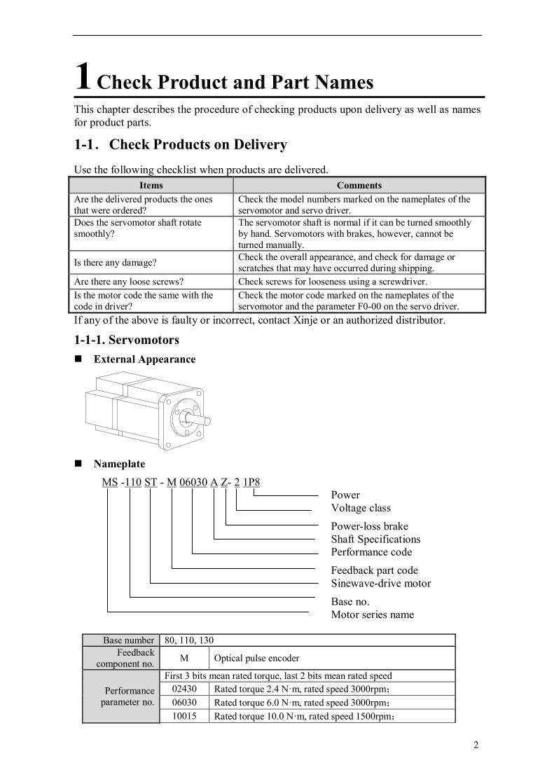
Nameplate
MS -110 ST - M 06030 A Z- 2 1P8 Power Voltage class Power-loss brake Shaft Specifications Performance code Feedback part code Sinewave-drive motor Base no. Motor series name
Base number 80, 110, 130 Feedback
component no. M Optical pulse encoder
Performance parameter no.
First 3 bits mean rated torque, last 2 bits mean rated speed 02430 Rated torque 2.4 N·m, rated speed 3000rpm; 06030 Rated torque 6.0 N·m, rated speed 3000rpm; 10015 Rated torque 10.0 N·m, rated speed 1500rpm;

3
Shaft spec A No bond B With bond
Power-loss brake
Vacant No Z With DC24V power-loss brake
Voltage class 2 220V 4 380V
Power 0P7 0.75kW 1P5 1.5kW 1P8 1.8kW
1-1-2.Servo Driver External Appearance
DS3 series
Nameplate
DS3 – 2 1P8
suitable motor capacity
0P7 0.75kW 1P5 1.5kW 1P8 1.8kW
Voltage level 2 220V 4 380V
Series name
Suitable motor capacity
Voltage class

4
1-2.Product Part Name
1-2-1.Servo motor
1-2-2.Servo Drivers DS3 series
Power and servo motor terminalPower supply input, connect to servo motor power terminal
CHARGE LEDIt lights when the main circuit power on. It lights after power off. and the charge is still in the capacitance, don’t touch the servo at this time.Panel Display the servo state, alarm, parameter inputPanel button Set the parameter
CN2 encoder port Connect to the encoder port on the servo motor.
Command/sequence input, signal output CN1 I/O signal port
POWER LED It lights when power on
COM2 Communicate with HMI, PLC and other devices
COM1 Connect to the PC and debug.
Encoder part Frame Flange
Output (transmission) shaft
5
2 Installation
This chapter describes precautions for servo motor and servo driver installation.
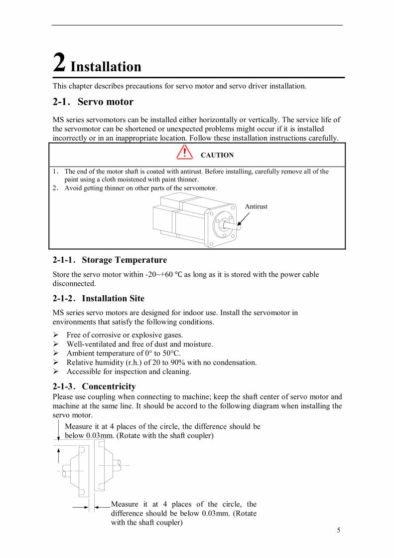
2-1.Servo motor MS series servomotors can be installed either horizontally or vertically. The service life of the servomotor can be shortened or unexpected problems might occur if it is installed incorrectly or in an inappropriate location. Follow these installation instructions carefully.
CAUTION
1. The end of the motor shaft is coated with antirust. Before installing, carefully remove all of the paint using a cloth moistened with paint thinner.
2. Avoid getting thinner on other parts of the servomotor.
2-1-1.Storage Temperature Store the servo motor within -20~+60 as long as it is stored with the power cable disconnected.
2-1-2.Installation Site MS series servo motors are designed for indoor use. Install the servomotor in environments that satisfy the following conditions. Free of corrosive or explosive gases. Well-ventilated and free of dust and moisture. Ambient temperature of 0° to 50°C. Relative humidity (r.h.) of 20 to 90% with no condensation. Accessible for inspection and cleaning.
2-1-3.Concentricity Please use coupling when connecting to machine; keep the shaft center of servo motor and machine at the same line. It should be accord to the following diagram when installing the servo motor.
Antirust
Measure it at 4 places of the circle, the difference should be below 0.03mm. (Rotate with the shaft coupler)
Measure it at 4 places of the circle, the difference should be below 0.03mm. (Rotate with the shaft coupler)

6
Note: (1) If the concentricity is not enough, it will cause the vibration and bearing damage. (2) When installing the coupler, prevent direct impact to the shaft. This can damage the encoder mounted on the shaft end at the opposite side of the load.
2-1-4.Orientation MS series servomotors can be installed either horizontally or vertically.
2-1-5.Handling Oil and Water Install a protective cover over the servomotor if it is used in a location with water or oil mist. Also use a servomotor with an oil seal when needed to seal the through-shaft section. The connector must install downwards.
2-1-6.Cable Stress Make sure that the power lines are free from bends and tension. Be especially careful to wire signal line cables so that they are not subject to stress because the core wires are very thin, measuring only 0.2 to 0.3mm2.
2-2.Servo Drivers The DS3 series servo drivers are base-mounted servo drivers. Incorrect installation will cause problems. Follow the installation instructions below.
2-2-1.Storage Conditions Store the servo driver within -20~+85, as long as it is stored with the power cable disconnected.
2-2-2.Installation Site The following precautions apply to the installation site.
Situation Installation Precaution
Installation in a Control Panel
Design the control panel size, unit layout, and cooling method so the temperature around the servo drivers does not exceed 50°C.
Installation Near a Heating Unit
Minimize heat radiated from the heating unit as well as any temperature rise caused by natural convection so the temperature around the servo drivers does not exceed 50°C.
Installation Near a Source of Vibration
Install a vibration isolator beneath the servo driver to avoid subjecting it to vibration.
Installation at a Site Exposed to Corrosive Gas
Corrosive gas does not have an immediate effect on the servo drivers, but will eventually cause electronic components and terminals to malfunction. Take appropriate action to avoid corrosive gas.
Through part of the shaft

7
Other Situations Do not install the servo driver in hot and humid locations or locations subject to excessive dust or iron powder in the air.
2-2-3.Orientation Install the servo driver perpendicular to the wall as shown in the figure. The servo driver must be oriented this way because it is designed to be cooled by natural convection or by a cooling fan.
2-2-4.Installation Follow the procedure below to install multiple servo drivers side by side in a control panel.
Servo Driver Orientation Install the servo driver perpendicular to the wall and the up side faces operator.
Cooling As shown in the figure above, leave enough space for servo drive to ensure better ventilation.
Side-by-side Installation

8
In the above diagram, leave 10mm at both sides on landscape; leave 50mm at both sides on portrait. Install cooling fan above servo drive. Make the temperature average in the control cabinet, prevent part temperature too high.
Environmental Conditions in the Control cabinet Ambient Temperature: 0~50 Humidity: 90%RH or less Vibration: 4.9m/s2 Condensation and Freezing: None Ambient Temperature for Long-term Reliability: 50°C maximum

9
3 Wiring
This chapter describes the procedure used to connect DS3 Series products to peripheral devices and gives typical examples of main circuit wiring as well as I/O signal connections.
3-1.Main Circuit Wiring This section shows typical examples of main circuit wiring for DS3 Series servo products, functions of main circuit terminals, and the power ON sequence. Observe the following precautions when wiring.
Caution
1. Do not bundle or run power and signal lines together in the same duct. Keep power and signal lines separated by at least 11.81inch(30cm)
2. Use twisted pair wires or multi-core shielded-pair wires for signal and encoder (PG) feedback lines. The maximum length is 118.11inch (3m) for reference input lines and is 787.40inch (20m) for encoder (PG) feedback lines.
3. Do not touch the power terminals for 5 minutes after turning power OFF because high voltage may still remain in the servo amplifier.
Please make sure to check the wiring after the CHARGE light is going off. 4. Avoid frequently turning power ON and OFF. Do not turn power ON or OFF more than once per
minute. Since the servo amplifier has a capacitor in the power supply, a high charging current flows for 0.2s when power is turned ON. Frequently turning power ON and OFF causes main power devices like capacitors and fuses to deteriorate, resulting in unexpected problems.
3-1-1.Names and Descriptions of Main Circuit Terminal DS3 series main circuit terminals: Terminal Function Explanation
1, 2
Current high harmonic suppression, DC reactor connection terminal
1 and 2 are shorted when out of factory. Connect DC reactor between them if needs to suppress the high harmonic.
R, S, T Power input terminal of main circuit
3-phase or single-phase 200~240V, 50/60Hz
Ground terminal Connect with motor ground and power supply ground.
U, V, W Motor terminal Connect with the motor P+, PB Regenerative resistor
terminal Connect regenerative resistor between P+ and PB

10
3-1-2.Typical Wiring Example
Note: For single power supply, connect any 2 terminals among R, S, T.
3-1-3.Winding Terminals on Servo motor Symbol 80 Series 110, 130 Series
PE 4 1 U 1 2 V 3 3 W 2 4
3-2.I/O Signals
This section describes I/O signals for the DS3 series servo driver.
3-2-1.Layout of CN1 The diagram is CN1 terminal layout (look at the solder side):
FIL
S
R
M
PG
UVW
P+
PB
Braking resistor
Servo drive
1MCCB
1MCCB : breaker for inverter
FIL: noise filter
1
2
T
or

11
3-2-2. CN1 terminal No. Terminal Explanation No. Terminal Explanation 1 GND Z-phase
transistor output 19 V-REF Analog setting, speed
2 CZ 20 GND 3 SO3- Output terminal
3 21 T-REF Analog setting, torque
4 SO3+ 22 GND 5 SO2- Output terminal
2 23 PL1 Power supply for open
collector command 6 SO2+ 24 PULS- Input pulse A or input
pulse signal 7 SO1- Output terminal 1
25 PULS+ 8 SO1+ 26 SIGN- Input pulse B or input
direction signal 9 +24V +24V for output terminal
27 SIGN +
10 SI7 Input terminal 7 28 PL2 Power supply for open collector command
11 SI6 Input terminal 6 29 NC Vacant 12 SI5 Input terminal 5 30 ZO+ Z-phase difference output 13 SI4 Input terminal 4 31 ZO- 14 NC Vacant 32 BO+ B-phase difference output 15 SI3 Input terminal 3 33 BO- 16 SI2 Input terminal 2 34 AO+ A-phase difference output 17 SI1 Input terminal 1 35 AO- 18 GND Ground 36 GND Ground
3-2-3.I/O Signals Input Signals
Item Input terminal
Function Reference chapter
Digital input
SI1~SI7 Multi-function input terminal 4-1-6, 4-4-2
Pulse input PULS+ PULS-
P2-00=1: A-phase pulse P2-00=2: pulse
4-3-2
SIGN+ SIGN-
P2-00=1: B-phase pulse P2-00=2: pulse direction (sign)
4-3-2
Analog input
V-REF Set speed or limit speed, analog input 3-2-4, 4-3-1 T-REF Set torque or limit torque, analog input 3-2-4, 4-3-7
Output Signals Item Output terminal Function Reference chapter
optocoupler SO1~SO3 Multi-functional output 3-2-4, 4-1-6, 4-4-3
Transistor output
CZ Z-phase transistor output 3-2-4 GND
Difference output
AO+, AO- A-phase difference output 3-2-4, 4-3-3 BO+, BO- B-phase difference output ZO+, ZO- Z-phase difference output
3-2-4.Interface Circuits This section shows examples of servo driver I/O signal connection to the host controller. The interface with the command input circuit
(1) Analog input circuit

12
Analog signal is speed command or torque command. The input resistance is shown below:
Speed command input: about 13kΩ
Torque command input: about 13kΩ
The max available voltage of input signal is ±10V.
(2) Position command input circuit
Open collector output (power supplied by user)
Please refer to below application and set the resistor R (current I is in the range of 7-15mA).
Application Vcc =24V ± 5% R=2.2kΩ
Vcc =12V ± 5% R=1kΩ
Vcc =5V ± 5% R=0Ω
Open collector output (power supplied by servo +5V)
Bus-driver output
+10V
-10V
CN1-19 /CN1-21 GND
0V
R=13KΩ
2KΩ 1W

13
The interface with the sequence input circuit
Use relay or open collector transistor circuit to connect. Please choose micro-current relay when using relay. Otherwise, the contactor will be not good.
The interface with the output circuit
There are 3 kinds of signal output circuit of servo unit. Connect with bus-driver output circuit Output encoder 2-phse pulse (AO+, AO-, BO+, BO-) and origin pulse (ZO+, ZO-) through bus-driver output circuit. Generally, it is used when the superior device is position control mode. Please use line receiving circuit at superior device side. Connect with open collector output circuit The servo drive support 1 channel origin pulse (Z-phase) transistor output , connect by optocoupler circuit.
Note: the max current and voltage of open collector output circuit: Voltage: DC 30V Current: DC 50mA Connect with optocoupler output circuit Servo alarm, servo ready and other sequence output circuit are made up by optocoupler circuit. Connect by relay, line receiving circuit or optocoupler.

14
Note: the max current and voltage of optocoupler: Voltage: DC 30V Current: DC 50mA
3-3.Wiring Encoders
3-3-1.Encoder Connections
3-3-2.CN2 Encoder Connector Terminal Layout CN2 Connector Terminal Layout The following diagrams are the layout of CN2 connector (face the solder side).
15
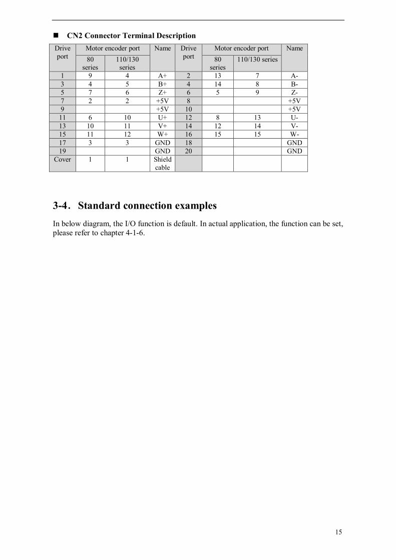
CN2 Connector Terminal Description Drive port
Motor encoder port Name Drive port
Motor encoder port Name 80
series 110/130
series 80
series 110/130 series
1 9 4 A+ 2 13 7 A- 3 4 5 B+ 4 14 8 B- 5 7 6 Z+ 6 5 9 Z- 7 2 2 +5V 8 +5V 9 +5V 10 +5V
11 6 10 U+ 12 8 13 U- 13 10 11 V+ 14 12 14 V- 15 11 12 W+ 16 15 15 W- 17 3 3 GND 18 GND 19 GND 20 GND
Cover 1 1 Shield cable
3-4.Standard connection examples In below diagram, the I/O function is default. In actual application, the function can be set, please refer to chapter 4-1-6.

16
3-4-1.Position control wiring
10 Ω
3.3KΩ
WV
PG
MV
3-phase AC 220V (50/60Hz)
AO+AO-
BO-BO+
ZO-ZO+
GND
Well deal with the shield wire
CN2
1
2
R
S
T
P+ PB
CZ
12
13
10
S-RDY+
S-RDY-
ALM+
ALM-
COIN-
COIN+
FIL
25
24 27 26
150Ω 23 28
+5V
PULS
SIGNPosition command
Self-define the output terminal
Servo enable ON (servo enable when ON) Paction (P action when ON) Ban forward run (ban forward when OFF) Ban reverse run
(ban reverse when OFF) Alarm reset
(clear alarm when ON) External torque limit at forward side (Limit when ON) External torque limit at reverse side (Limit when ON)
PULS-
SIGN-
PL1
PL2
Power for
Open collectorcommand
11
15 16
17
9
/N-CL /P-CL
/ALM-RST
/N-OT
/P-OT
/P-CON /S-ON
+24VIN
3
4
5
6
7
8
1
2
31
30 333235
34
U U
PE W
PULS+
SIGN+
Encoder Signal output

17
3-4-2.Speed control wiring
10 Ω
3.3KΩ
T-REF
V-REF
A/D
WV
PG
M
3-phase AC220V (50/60Hz)
AO+ AO-
BO-BO+
ZO-ZO+
GND
EncoderSignal output
Well deal with the shield cable
CN2
1
2
R
S
T
P+
PB
CZ
20 19
21
22
13
10
S-RDY+
ALM+
ALM-
V-CMP +
Speed command ±10V/rated speed
Torque limit input±10V/rated torque
FIL
Self-define the output terminal /ALM-RST
/N-OT /P-OT /P-CON
/S-ON +24VIN
/P-CL
/N-CL 11
15
16
12
17
9
3
45
6
7
8
1
2
31 30 33 32 3534
U
WPE
VU
GND
GND
S-RDY-
V-CMP -
Servo enable ON (servo enable when ON) Paction (P action when ON) Ban forward run (ban forward when OFF) Ban reverse run
(ban reverse when OFF) Alarm reset
(clear alarm when ON) External torque limit at forward side (Limit when ON) External torque limit at reverse side (Limit when ON)

18
3-4-3.Torque control wiring
3-5.Communication Port
3-5-1.Serial Port 1 (COM1) COM1 supports RS232, and is often used to connect with PC for debugging. Before doing this, “F5-00” on the panel should be set to “C-OUT”, and the panel will be invalidated. On leaving this status, use the panel to exit, and PC disconnect from servo driver. Please refer to chapter 5-4-5. Pin diagram of com1 face to the drive:
123456
78
10 Ω
3.3KΩ
T-REF
V-REF
A/D
WV
PG
M
3-phase AC220V (50/60Hz)
AO+ AO-
BO-BO+
ZO-ZO+
GND
EncoderSignal output
Well deal with the shield cable
CN2
1
2
R
S
T
P+
PB
CZ
20 19
21
22
13
10
S-RDY+
ALM+
ALM-
V-CMP +
Speed limit input ±10V/rated speed
Torque command±10V/rated torque
FIL
Self-define the output terminal /ALM-RST
/N-OT /P-OT /P-CON
/S-ON +24VIN
/P-CL
/N-CL 11
15
16
12
17
9
3
45
6
7
8
1
2
31 30 33 32 3534
U
WPE
VU
GND
GND
S-RDY-
V-CMP -
Servo enable ON (servo enable when ON) Paction (P action when ON) Ban forward run (ban forward when OFF) Ban reverse run
(ban reverse when OFF) Alarm reset
(clear alarm when ON) External torque limit at forward side (Limit when ON) External torque limit at reverse side (Limit when ON)
Pin Name Explanation 4 RXD RS232 receive 5 TXD RS232 send 8 GND RS232 ground

19
Communication parameters of COM1 cannot be changed: Baudrate: 19200bps; Data bits: 8 bits; Stop bits: 1 bit; Parity: even parity; Modbus station number: 1. Note: please use the cable provided by Xinje Company.
3-5-2.Serial Port 2(COM2) Serial port 2 supports RS485 and RS232. It supports Modbus-RTU protocol, can realize 1:N communication. It is used to communicate with PLC, HMI. The communication parameters of com2 can be configured. The pin diagram of com2 faces to drive side:
Set COM2 parameters via P0-04: Code Function Default Setting range
P0-04.0 Baud rate 3 0~9 0:300 1:600
2:1200 3:2400 4:4800 5:9600
6:19200 7:38400 8:57600
9:115200 P0-04.1 Data bit 0 0:8 P0-04.2 Stop bit 0 0:1 P0-04.3 Parity bit 2 0~2
0:no parity 1:odd parity 2:even parity
Modbus station number can be set via P0-03:
Parameter Number Name Unit Default Setting Range
P0-03 Modbus Station Number - 1 1~255
Note: Parameters above will take effect after repower on.
Pin Name Explanation 2 RXD RS232 receive 3 TXD RS232 send 5 GND RS232 ground 7 B RS485- 4 A RS485+
20
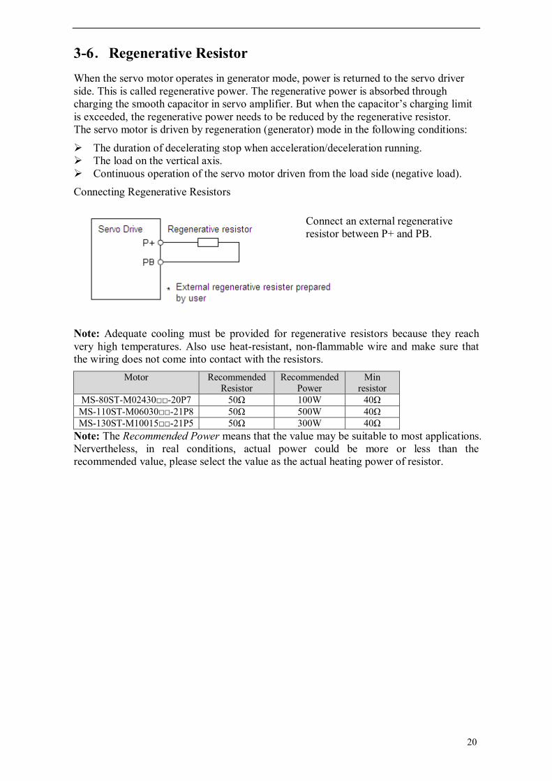
3-6.Regenerative Resistor When the servo motor operates in generator mode, power is returned to the servo driver side. This is called regenerative power. The regenerative power is absorbed through charging the smooth capacitor in servo amplifier. But when the capacitor’s charging limit is exceeded, the regenerative power needs to be reduced by the regenerative resistor. The servo motor is driven by regeneration (generator) mode in the following conditions:
The duration of decelerating stop when acceleration/deceleration running. The load on the vertical axis. Continuous operation of the servo motor driven from the load side (negative load). Connecting Regenerative Resistors
Note: Adequate cooling must be provided for regenerative resistors because they reach very high temperatures. Also use heat-resistant, non-flammable wire and make sure that the wiring does not come into contact with the resistors.
Motor Recommended Resistor
Recommended Power
Min resistor
MS-80ST-M02430-20P7 50Ω 100W 40Ω MS-110ST-M06030-21P8 50Ω 500W 40Ω MS-130ST-M10015-21P5 50Ω 300W 40Ω
Note: The Recommended Power means that the value may be suitable to most applications. Nervertheless, in real conditions, actual power could be more or less than the recommended value, please select the value as the actual heating power of resistor.
Connect an external regenerative resistor between P+ and PB.

21
4 Parameters This chapter introduces the DS3 servo parameters and operation.
4-1.Parameters Onset time: “”servo OFF;
“”power on; “√”can set during running.
Parameter: PX-XX=×× ×× PX-XX. H PX-XX.L
4-1-1. Functions select P0 Modbus address: 0000~00FF P0-
Function Unit Default Range Onset time
Chapter
00 Main mode - 0 0 4-4-1 01 Submode 1 - 0 0~7 4-4-1 02 Submode 2 - 0 0~7 4-4-1 03 Modbus station NO. of COM2 - 1 1~255 3-5-2 04 Parameters of COM2 - 2206 0~2209 3-5-2 05 Select rotate direction - 0 0, 1 4-2-1 06 06.L: stop mode of servo OFF or
alarm 0: stop by dynamic brake (DB). Keep DB after stop. 1: stop by dynamic brake (DB). Switch to inertia motion after stop. 2: stop inertia motion. Motor is not power on. Stop by mechanical friction.
- 2 0~2 4-5-1
06.H: stop mode when over range(OT). 0: stop by dynamic brake (DB). Switch to inertia motion after stop. 1: inertia stop, keep inertia motion after stop. 2: deceleration stop. Switch to zero clamp after stop. Torque: P4-06. 3: deceleration stop. Switch to inertia motion after stop. Torque: P4-06 urgent stop torque.
- 2 0~3 4-2-2
07 T-REF distribution 0: no 1: T-REF is assigned to external torque limit input. 2: undefined. 3: T-REF is assigned to external torque limit input when P-CL, N-CL is ON.
- 0 0~3 4-2-4
08 V-REF distribution 0: no 1: V-REF is assigned to external
- 0 0, 1 4-2-5

22
speed limit input 09 Reserved - 10 Reserved
4-1-2. Control parameters P1 Modbus address: 0100~01FF P1- Name Unit Default Range Effect
time Chapter
00 Speed loop gain 1Hz 100 1~500 √ 4-8-1 01 Speed loop integral time
constant 0.1ms 400 1~5000 √ 4-8-1
02 Position gain 1/s 30 1~200 √ 4-8-1 03 Inertia ratio % 0 0~20000 √ 04 Second speed loop gain 1Hz 150 1~500 √ 4-8-3 05 Second speed loop integral
time 0.1ms 100 1~5000 √ 4-8-3
06 Second position loop gain 1/s 80 1~200 √ 4-8-3 07 Reserved 08 Reserved 09 Position loop feedforward
gain 1% 0 0~100 √ 4-3-2
10 Feedforward filter time 0.01ms 0 0~65535 √
4-1-3. Position control P2 Modbus address: 0200~02FF P2- Function Unit Default Range Effect
time Chapter
00 Command pulse state 1: AB-phase pulse (90 degree phase, 4 times) 2: sign + pulse
- 2 1, 2 4-3-2
01 Position command filter select 0: first-order inertia filter 1: smooth filter
- 0 0, 1 4-7-1
02 Electronic gear ratio (molecular)
- 1 1~65535 4-3-5
03 Electronic gear ratio (denominator)
- 1 1~65535 4-3-5
04 Position command filter time ms 0 0~100 4-7-1 05 Reserved 06 Command pulse frequency at
rated speed 100Hz 5000 1~10000 4-3-1
07 Speed command pulse filter time
0.1ms 20 0~1000 √ 4-3-1

23
4-1-4. Speed control P3 Modbus address: 0300~03FF P3- Name Unit Default Range Effect
time Chapter
00 Analog value of rated speed
0.01V 1000 150~3000 4-3-1
01 Internal set speed 1 rpm 100 -5000~+5000 √ 4-3-6 02 Internal set speed 2 rpm 200 -5000~+5000 √ 4-3-6 03 Internal set speed 3 rpm 300 -5000~+5000 √ 4-3-6 04 JOG speed rpm 100 0~1000 √ 4-4-4 05 Soft-start speed up
time ms 0 0~65535 4-3-6
06 Soft-start speed down time
ms 0 0~65535 4-3-6
07 Speed command filter time
0.01ms 0 0~65535
08 Speed feedback filter time
0.01ms 20 0~65535
09 Max speed limit (max speed)
rpm Rated speed 3000:4000
Rated speed 1500:2000
0~5000
4-1-5. Torque control P4 Modbus address: 0400~04FF P4-
Name Unit Default Range Effect time
Chapter
00 Analog value of rated torque 0.01V 1000 150~3000 4-3-7 01 Torque command filter time 0.01ms 0 0~65535 02 Forward torque limit 1% 300 0~300 √ 4-2-4 03 Reverse torque limit 1% 300 0~300 √ 4-2-4 04 Forward external torque limit 1% 100 0~300 √ 4-2-4 05 Reverse external torque limit 1% 100 0~300 √ 4-2-4 06 Urgent stop torque 1% 300 0~300 4-2-2 07 Internal speed limit when
torque control rpm 2000 1~5000 4-2-5
08 Reserved 09 Internal torque command 1% 0 -300~300 √ 4-3-7
4-1-6. Signal P5 Modbus address: 0500~05FF P5-
Name Unit Default Range Effect time
Chapter
00 Positioning completed width /COIN Command pulse
7 0~250 4-6-3
01 Zero clamp speed /ZCLAMP rpm 10 0~300 4-5-2 02 Rotate check speed /TGON rpm 20 1~1000 4-6-5 03 Same speed signal check width
/V-CMP rpm 10 1~250 4-6-4
04 Near signal width /NEAR Command pulse
50 0~10000 4-6-7
05 Bias pulse limit 256* command
1000 0~65535 4-8-1

24
pulse 06 Servo OFF delay time(Brake
command) 1ms 0 0~500 4-2-6
07 Brake command output speed rpm 100 0~5000 4-2-6 08 Brake command wait time 1ms 500 10~1000 4-2-6 09 Reserved 10 10.L: input signal distribution
0: use default set for external input, P5-10.H~P5-17.H are unchangable 1: set external input, P5-10.H~P5-17.H are changeable.
- 1 0, 1 4-4-2
10.H: /S-ON servo signal 00: set signal to invalid. 01: input positive signal to SI1 02: input positive signal to SI2 03: input positive signal to SI3 04: input positive signal to SI4 05: input positive signal to SI5 06: input positive signal to SI6 07: input positive signal to SI7 80: set signal to valid 81: input negative signal to SI1 82: input negative signal to SI2 83: input negative signal to SI3 84: input negative signal to SI4 85: input negative signal to SI5 86: input negative signal to SI6 87: input negative signal to SI7
- 01 00~C7 4-6-2
11 11.L: /P-CON proportion action command Ibid
- 02 00~C7 4-8-2
11.H: P-OT ban forward drive Ibid
- 83 00~C7 4-2-2
12 12.L: N-OT ban reverse drive Ibid
- 84 00~C7 4-2-2
12.H: /ALM-RST reset alarm Ibid
- 05 00~C7 4-6-1
13 13.L: /P-CL external torque limit at forward side Ibid
- 06 00~C7 4-2-4
13.H: /N-CL external torque limit at reverse side Ibid
- 07 00~C7 4-2-4
14 14.L: /SPD-D internal speed select Ibid
- 00 00~C7 4-3-6
14.H: /SPD-A internal speed select Ibid
- 00 00~C7 4-3-6
15 15.L: /SPD-B internal speed select Ibid
- 00 00~C7 4-3-6
15.H: /C-SEL control mode select Ibid
- 00 00~C7 4-4-1
16 16.L: /ZCLAMP zero clamp Ibid
- 00 00~C7 4-5-2
16.H: reserved 17 17.L: /G-SEL gain switching
Ibid - 00 00~C7 4-8-3
17.H: /CLR clear pulse offset Ibid
- 00 00~C7 4-3-2
18 Reserved 19 Input terminal filter time 5ms 4 0~100

25
20 20.L: /COIN positioning completed 00: not output to terminal 01: output positive signal from SO1 02: output positive signal from SO2 03: output positive signal from SO3 81: output negative signal from SO1 82: output negative signal from SO2 83: output negative signal from SO3
- 01 00~83 4-6-3
20.H: /V-CMP same speed checking Ibid
- 00 00~83 4-6-4
21 21.L: /TGON rotation checking Ibid
- 00 00~83 4-6-5
21.H: /S-RDY ready Ibid
- 03 00~83 4-6-6
22 22.L: /CLT torque limit Ibid
- 00 00~83 4-2-4
22.H: /VLT speed limit checking Ibid
- 00 00~83 4-2-5
23 23.L: /BK brake interlocking Ibid
- 00 00~83 4-2-6
23.H: /WARN warn Ibid
- 00 00~83 4-6-8
24 24.L: /NEAR near Ibid
- 00 00~83 4-6-7
24.H: /ALM alarm Ibid
- 02 00~83 4-6-1
25 Reserved
4-2.Mechanical setting
4-2-1. Switch motor direction The reverse mode can change motor rotation direction without changing the motor wiring. The servo encoder AB-phase output changed at this time. Default setting is forward direction, the motor is rotating counterclockwise. Default setting Reverse mode Forward command
Reverse command
Reverse mode setting Set reverse mode through P0-05.
Parameter Function Unit Range Default P0-05 Select motor rotate direction - 0, 1 0

26
P0-05 Contents 0 CCW is forward direction, look at motor
load side Default value
1 CW is forward direction, look at motor load side
Reverse mode
Note: please repower on the servo to make the setting effective.
4-2-2. Overrange setting (P-OT, N-OT) Overrange function can stop the machine when it exceeds the movable range.
Overrange function Connect P-OT, N-OT (input signal of limit switch) to CN1 of servo. Input signal Function Control mode
P-OT Forward drive limit switch (forward overrange)
Speed control, torque control, position control
N-OT Reverse drive limit switch (reverse overrange)
Speed control, torque control, position control
Please connect limit switch as the following diagram to avoid machine damage when line driving.
Driving state when P-OT, N-OT are ON/OFF.
Input signal Input state Input mode Terminal state Description
/P-OT (P5-11.H)
ON Signal valid
Input positive signal
CN1-9 connect to 24V
SI=0V (optocoupler ON) Ban forward
drive. (reverse is valid) Input negative
signal SI=24V or cut off (optocoupler OFF)
OFF Signal invalid
Input positive signal
SI=24V or cut off (optocoupler OFF) Enable forward
drive. (normal running state) Input negative
signal SI=0V
(optocoupler ON)
/N-OT (P5-12.L)
ON Signal valid
Input positive signal
CN1-9 connect to 24V
SI=0V (optocoupler ON) Ban reverse
drive. (forward is valid) Input negative
signal SI=24V or cut off (optocoupler OFF)
OFF Signal invalid
Input positive signal
SI=24V or cut off (optocoupler OFF) Enable reverse
drive. (normal running state) Input negative
signal SI=0V
(optocoupler ON)
Use/unused overrange signal Set below parameter to select use/unused overrange signal. The default value is to use overrange signal. Parameter Explanation Unit Range Default
P5-11.H
P-OT always protect: set P5-11.H to 80, rarely used. P-OT always not protect: set P5-11.H to 00, used when no limit protection. Terminal protect: assign bit0 of P5-11.H to
- 00~C7 83
Reverse side
limitswitch
limit switch
N-OT
P-OT Servo unit
Servo motor
Forward side

27
SI1~SI7 input terminal; bit8 of P5-11.H select always ON/OFF of limit switch, 8 is always ON, 0 is always OFF.
P5-12.L
N-OT always protect: set P5-12.L to 80, rarely used. N-OT always not protect: set P5-12.L to 00, used when no limit protection. Terminal protect: assign bit0 of P5-12.L to SI1~SI7 input terminal; bit8 of P5-12.L select always ON/OFF of limit switch. 8 is always ON, 0 is always OFF.
- 00~C7 84
Note: stranded pulse will produce after motor stop by overrange function in position control mode. Clear the stranded pulse by clear signal.
Motor stop mode when overrange Motor stop mode when using overrange function. Parameter Function Unit Range Default P0-06.H Motor stop mode when servo is
overrange - 0~3 2
P0-06.H value Contents
0 Stop by dynamic brake (DB). Change to inertia motion after stop. 1 Inertia stops. Keep inertia motion after stop. 2 Deceleration stops. Change to zero clamp after stop.
Torque setting: P4-06 urgent stop torque. 3 Deceleration stops. Change to inertia motion after stop.
Torque setting: P4-06 urgent stop torque. Note: 1. If P0-06.H=0/1, servo enable signal is forced set to 0 when overrange signal arrives; If P0-06.H=3, servo enable signal is forced set to 0 after motor stop when overrange signal arrives; If P0-06.H=2, servo enable signal will not be forced set to 0 as long as it is always effective. 2. Stop judging is based on rotate speed P5-02 (unit: rpm).
4-2-3. Motor stop mode when servo is OFF DS series servo drive will close servo enable in these cases:
Power supply is ON, input signal is OFF (/S-ON) Alarming (/ALM) Power supply is OFF
Parameter Function Unit Range Default P0-06.L Motor stop mode when servo is OFF - 0~2 2
P0-06.L Contents
0 Stop by dynamic brake (DB). Keep DB state after stop. 1 Stop by dynamic brake (DB). Change to inertia motion after stop. 2 Stop inertia motion. Motor is power off. Stop by mechanical friction.
Please refer to chapter 4-5-1 for DB brake.

28
4-2-4. Torque limit Torque control, speed contrl and position control have torque limit function. Torque output exceeds limit value, /CLT signal will be ON. Parameter P5-22.L can assign /CLT to any terminal among SO1~SO3.
Signal name Output state Output mode Terminal state Description
/CLT (P5-22.L)
Output is ON, signal
is valid
Output positive signal DS3
S0+ and S0- pass through Torque is
overrange Output negative signal
S0+ and S0- shut off
Output is OFF, signal
is invalid
Output positive signal
DS3
S0+ and S0- shut off Torque is
normal Output negative signal
S0+ and S0- pass through
DS series servo has 4 kinds of torque limit modes: 1. Internal torque limit 2. External torque limit 3. Torque limit based on analog (T-REF) 4. Torque limit based on external torque limit and analog (T-REF) Internal torque limit (max output torque limit) Internal torque limit is to limit the the max output torque via parameter. Parameter Function Unit Range Default Control mode
P4-02 Forward torque limit
1% 0~300 300 Speed control, position control
P4-03 Reverse torque limit
1% 0~300 300 Speed control, position control
The setting of the parameters is always effective. The setting unit is percentage of motor rated torque. If the setting value exceeds the max motor torque, it will limit the motor as the actual max torque. The default value is 300%. Note: if P4-02 and P4-03 are set too small, the torque will be not enough when motor accelerates or decelerates. External torque limit via input signal External torque limit is used when machine needs torque limit or it needs torque limit at certain moment. For example, the applications of press stop action or robot workpiece holding. The parameters will be effective by the input signal. Parameter Function Unit Range Default Control mode
P4-04 Forward external
torque limit
1% 0~300 100 Speed control, torque control, position control
P4-05 Reverse external
torque limit
1% 0~300 100 Speed control, torque control, position control
Note: the unit is percentage of rated motor torque. The limit of rated torque is 100%. Signal Input state Input mode Terminal state Description
/P-CL (P5-13.L)
ON, signal is valid
Input positive signal CN1-9
connect to 24V
SI=0V (optocoupler ON)
Forward external torque limit, limit value P4-02 or P4-04 (limit the minor one)
Input negative signal
SI=24V or cut off (optocoupler OFF)

29
OFF, signal is invalid
Input positive signal
SI=24V or cut off (optocoupler OFF)
Forward external torque not limit (use internal torque limit P4-02) Input negative
signal
SI=0V (optocoupler ON)
/N-CL (P5-13.H)
ON, signal is valid
Input positive signal
CN1-9 connect to 24V
SI=0V (optocoupler ON)
Reverse external torque limit, limit value P4-03 or P4-05 (limit the minor one)
Input negative signal
SI=24V or cut off (optocoupler OFF)
OFF, signal is invalid
Input positive signal
SI=24V or cut off (optocoupler OFF)
Reverse external torque not limit (use internal torque limit P4-03) Input negative
signal
SI=0V (optocoupler ON)
Torque limit by analog voltage command The function is to limit the torque by analog voltage command. Input the analog voltage command to terminal T-REF. this function only can be used in speed control or position control mode. The diagram of using this function in speed control mode:
Note: the analog voltage for torque limit has no polarity. It is fit for forward and reverse direction.
Parameter Function Unit Range Default P0-07 T-REF distribution - 0~3 0
0: no 1: T-REF is used to external torque limit input. 2: un-defined 3: When P-CL, N-CL are ON, T-REF is used to external torque limit input. Here we set P0-07 to 1. Set rated torque analog value via P4-00
-
+ Analog of rated
speed P3-00 V-REFSpeed
command
Torque
Limit value T-REF Input torque
gain P4-00
Speed feedback
Speed loop
gain P1-00 Integral time
constant of
speed loop P1-01
+
+
P4-02
Forward torque
limit value
P4-03Reverse torque
limit value
torque command
Servo unit
30
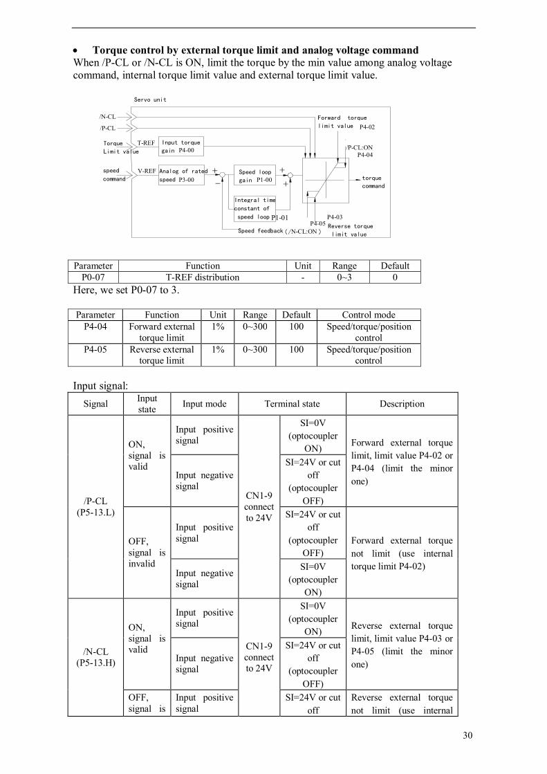
Torque control by external torque limit and analog voltage command When /P-CL or /N-CL is ON, limit the torque by the min value among analog voltage command, internal torque limit value and external torque limit value.
Parameter Function Unit Range Default P0-07 T-REF distribution - 0~3 0
Here, we set P0-07 to 3. Parameter Function Unit Range Default Control mode
P4-04 Forward external torque limit
1% 0~300 100 Speed/torque/position control
P4-05 Reverse external torque limit
1% 0~300 100 Speed/torque/position control
Input signal:
Signal Input state Input mode Terminal state Description
/P-CL (P5-13.L)
ON, signal is valid
Input positive signal
CN1-9 connect to 24V
SI=0V (optocoupler
ON) Forward external torque limit, limit value P4-02 or P4-04 (limit the minor one) Input negative
signal
SI=24V or cut off
(optocoupler OFF)
OFF, signal is invalid
Input positive signal
SI=24V or cut off
(optocoupler OFF)
Forward external torque not limit (use internal torque limit P4-02)
Input negative signal
SI=0V (optocoupler
ON)
/N-CL (P5-13.H)
ON, signal is valid
Input positive signal
CN1-9 connect to 24V
SI=0V (optocoupler
ON) Reverse external torque limit, limit value P4-03 or P4-05 (limit the minor one) Input negative
signal
SI=24V or cut off
(optocoupler OFF)
OFF, signal is
Input positive signal
SI=24V or cut off
Reverse external torque not limit (use internal
Speed feedback
- +Analog of rated
speed P3-00 V-REFspeed
command
Torque
Limit value
T-REF Input torque
gain P4-00
/N-CL
/P-CL
Speed loop
gain P1-00
Integral time
constant of
speed loop
+ +
torque command
P4-03Reverse torque
limit value
P4-02
P4-04
/P-CL:ON
P4-05(/N-CL:ON )
Servo unit
P1-01
Forward torque
limit value

31
invalid (optocoupler OFF)
torque limit P4-03)
Input negative signal
SI=0V (optocoupler
ON)
4-2-5. Speed limit in torque control mode It outputs /VLT signal to limit the speed in torque control mode.
Signal Output state Output mode Terminal state Description
/VLT
Output is ON,signal is
valid
Output positive signal DS3
S0+ and S0- pass through Speed
over-range Output negative signal
S0+ and S0- shut off
Output is OFF, signal
is invalid
Output positive signal DS3
S0+ and S0- shut off Speed normal Output negative
signal S0+ and S0- pass
through Below parameter will assign the /VLT signal to the output terminal:
Parameter Function Unit Range Default P5-22.H Output terminal distribution /VLT - 00~83 00
The default setting is 00, output between SO1+ and SO1-. Please see chapter 4-4-3 for details. Internal speed limit Parameter Function Unit Range Default Control mode
P4-07 Set the limit speed rpm 0~5000 2000 Torque control External speed limit analog value P0-08 is set to 1; V-REF is set to external speed limit input. The final limit value is the smaller one between P4-07 and V-REF.
4-2-6. Power-off brake (BK) BK is used when servo controls the vertical shaft. The purpose to use servo motor with brake: when the power supply is OFF, the movable part will not move by gravity.
Prevent part moving by gravity when power is off
Power-off brake
Servo motor
The power-off brake in MS series servo motor is no excitation model. It cannot be used to brake but only to keep the stop state of motor. The torque of this brake is above 120% of rated torque of servo motor.

32
Wiring example The brake ON/OFF circuit includes /BK output signal and brake power supply. Typical wiring diagram is shown below:
Note: 1. The power supply of BK is DC 24V. 2. SO1+ and SO1- are the terminals of DS3. In above diagram, SO1 terminal outputs BK signal, set P5-23.L to 81. Output signal State Control mode
BK Brake interlocking output
Speed/position/torque mode
Signal name Output state Output mode Terminal state Description
/BK
Output is
ON, signal is valid
Output positive signal DS3
S0+ and S0- pass through Brake close
(brake) Output negative signal
S0+ and S0- shut off
Output is OFF, signal
is invalid
Output positive signal DS3
S0+ and S0- shut off Brake open Output negative
signal S0+ and S0- pass
through
Servo OFF delay time (after servo motor stop) The machine will move with gravity because of servo OFF delay time. Please use below parameter to adjust.
Parameter Function Unit Range Default Control mode
P5-06 Servo OFF delay time
(brake command)
1ms 0~500 0 Speed/torque/position control
R
S
U
V
W
PE
SO1+
SO1-
U
V
W
PE M
PG CN2
BK 1
2
3
Servo drive
+24V
BK-RY
Power
supply
Servo motor with BK
+24V
BK-RY
T

33
The time of servo OFF and /BK output when set servo motor with brake.
The standard setting is that /BK output and servo OFF at the same time. But the machine will move with gravity at this time. Delay the servo OFF by parameter can avoid the movement. The setting is the time when servo motor stop. Brake ON parameter (servo motor is rotating) The brake action is P5-07 and P5-08 when servo motor is rotating. Note: motor will be power off when alarming. The machine will move because of gravity before brake is ON. Use power-off brake when motor stops rotating. Please set below parameters: Parameter Function Unit Range Default Control mdoe
P5-07 Brake command output speed
rpm 0~5000 100 Speed/torque/position control
P5-08 Brake command wait time
1ms 10~1000 500 Speed/torque/position control
Set the brake time of servo OFF when inputing /S-ON or alarming.
The brake is used to keep the position, it must work at the right time when motor stop. Please set the parameter as the machine movement. The condition of /BK change ON to OFF when motor is rotating: 1. Motor speed is lower than P5-07 after servo is OFF 2. the time is larger than P5-08 after servo is OFF If the set speed is larger than max speed in P5-07, the real value is always max speed.
/S-ON input
/BK output
Servo OFF Servo ON
Brake OFF Brake ON
Motor power on
Servo OFF delay time
Motor power on
Motor power off
/S-ON input or alarm Power is off
Motor speed (rpm)
/BK output P5-07
Servo ON Servo OFF
Brake ON Brake OFF
P5-08
DB stop or Free stop

34
4-3.The setting fit for superior device
4-3-1. Speed command Speed command is transferred to speed command input terminal (see below diagram). 1. Analog input
Input signal State Control mode V-REF Speed command input Speed control GND Ground Speed control
It is used to speed control (analog command). Make sure to wiring in normal speed control mode. Control the motor speed as the input voltage between V-REF and GND.
Setting example P3-00 = 600, 6V corresponding speed. Please see below example. Speed command Direction Speed For motor of 3000rpm
+6V Forward Rated speed 3000rpm
+1V Forward 1/6 of rated speed 500rpm
-3V Reverse -(1/2) of rated speed -1500rpm Change the input voltage range via P3-00.
Example of input circuit Make sure to use stranded wire to avoid interference. Please connect to the speed command output terminal of host machine in position control mode.

35
Please adjust the value of P3-00 as the output voltage. Adjust the input gain of speed command via below parameter. Parameter Function Unit Range Default Control mode
P3-00 Analog value of rated speed
0.01V 150~3000 1000 Speed control, torque control
Set the voltage range of speed command V-REF according to the host device and output condition.
The command voltage is set to 10V when out of factory. 2. Input pulse frequency The speed command is decided by external pulse frerquency, but not pulse quantity. The circuit wiring is the same to position command. AB-phase pulse (4-time frequency) and direction plus pulse can be selected. Select pulse mode via below parameter:
Parameter Function Unit Range Default Control mode P2-00 Pulse command
mode - 1, 2 2 Position control,
speed control Please select the pulse command mode as the host device condition: Parameter Set value Pulse mode
P2-00 1 AB-phase pulse (4-time frequency) 2 Pulse plus direction
Adjust the input gain of pulse frequency speed command by below parameter: Parameter Function Unit Range Default Control mode
P2-06 Pulse frequency of rated speed
100Hz 1~10000 5000 Speed control
Adjust the filter time of pulse frequency speed command by below parameter: Parameter Function Unit Range Default Control
mode P2-07 Filter time of speed
command 0.1ms 0~1000 20 Speed
control
4-3-2.Position command The position commands contain pulse input, sign input, clear input. Pulse input command
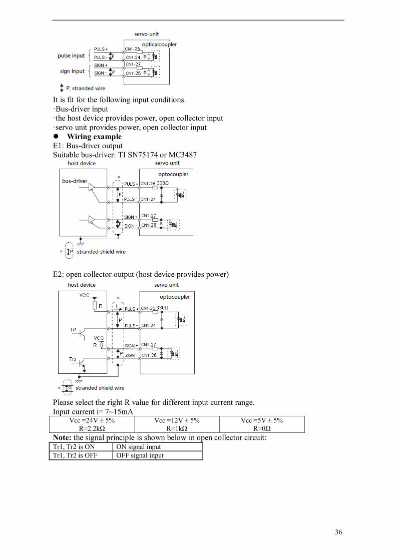
36
It is fit for the following input conditions. ·Bus-driver input ·the host device provides power, open collector input ·servo unit provides power, open collector input Wiring example E1: Bus-driver output Suitable bus-driver: TI SN75174 or MC3487
E2: open collector output (host device provides power)
Please select the right R value for different input current range. Input current i= 7~15mA
Vcc =24V ± 5% R=2.2kΩ
Vcc =12V ± 5% R=1kΩ
Vcc =5V ± 5% R=0Ω
Note: the signal principle is shown below in open collector circuit: Tr1, Tr2 is ON ON signal input Tr1, Tr2 is OFF OFF signal input

37
E3: open collector output (servo provides power)
The state of pulse command Please set the pulse command state via below parameter: Parameter Function Unit Range Default Control mode
P2-00 Pulse command state - 1, 2 2 Position mode, speed mode The state of pulse command: Parameter Settings State
P2-00 1 AB-phase pulse (4-time frequency) 2 Pulse + direction
AB-phase pulse (4-time frequency):
The time of pulse command signal: State of pulse command Electrical specification Mark
Sign + pulse (SIGN+PULS signal) Max frerquency: Bus-driver: 500kbps Open transistor: 200kbps
t1,t2 ≤ 0.1μs t3,t7 ≤ 0.1μs t4,t5,t6 > 3μs τ≥ 2.5μs (τ/T) × 100 = 40%~60%
SIGN 1=forward 0=reverse
90° phase difference 2-phase pulse (A-phase +B-phase) Max frequency: Bus-driver: 500kbps Open transistor: 200kbps

38
t1,t2 ≤ 0.1μs τ≥ 2.5μs (τ/T) × 100 = 40% ~ 60%
Clear pulse input /CLR Signal Input
state Input mode Terminal state Description
/CLR
ON, signal is
valid
Input positive signal
CN1-9 connects to 24V
SI=0V (optocoupler is ON) Clear the shift
counter Input negative signal
SI=24Vor cut off (optocoupler is OFF)
OFF, signal is invalid
Input positive signal
SI=24V or cut off (optocoupler is OFF)
Work normally, not clear shift
counter Input negative signal
SI=0V (optocoupler is ON)
After set ON /CLR signal, shift counter is set to 0, and position loop is set to current position. Control diagram
4-3-3.Encoder position output DS3 series can output encoder position. This function can be used to configure the position loop in the host device.
The output circuit is bus-driver output. Please wiring as the following circuit.
Servo unit (position control mode) Pulse Command + + + - Encoder output
Feedforward gain P1-09
Smooth/first filter (P2-01/P2-04)
Current loop
Kp (P1-02)
Differential
Speed loop
Deviation counter
Filter P1-10
B/A (P2-02/ P2-03)
Servo motor
Encoder

39
Output signal Connect the output signal when the host device needs to configure the position loop and make position controlling.
4-3-4.Sequence I/O signal The sequence I/O signal can control the servo action. Please connect them as your needs.
The wiring of input signal
The wiring of output signal
Suitable line receiver: same product of TI SN7517.5 or MC3486 R (terminal resistor): 220~470Ω C (decoupling capacitor): 0.1µF

40
4-3-5.Electronic gear Electronic gear function can set the motor moving distance to any value. The host device which sends the command don’t need to consider the deceleration ratio and encoder pulse quantity.。
Set the electronic gear Calculate the electronic gear ratio (B/A) using the following procedure, and set the values in parameters P2-02 and P2-03.
1. Check equipment specifications related to the electronic gear:
Deceleration ratio Ball screw pitch Pulley diameter
2. Check the number of encoder pulses for the servo motor.
3. Determine the reference unit. A reference unit is the minimum position unit used to move a load (Minimum unit
of the host device). Reference unit can be 0.1in or 0.01in or 0.01mm or 0.001mm, etc. Input one pulse command, the device moves 1 reference unit distance. When the reference unit is 1µm, input 50000 reference units, the load moves
50000 × 1µm = 50mm. 4. Find the reference unit of load shaft turning 1 circle.
The reference unit of load shaft turning 1 circle is: The moving distance of load shaft turning 1 circle/reference unit For example: ball screw pitch=5mm, reference unit=0.001mm, so 5/0.001=5000.
Ball Screw Disc Table Belt and Pulley

41
5. Find the electronic gear ratio (B/A): The ratio of motor shaft and load shaft is m/n (motor turns m circles, load shaft turns n circles)
Please confirm if the electronic gear meets the below condition:
The servo driver will not work properly if the electronic gear ratio exceeds this range. In that case, modify either the mechanical structure or the reference unit. 6. Set the parameters Reduce the electronic gear ratio to the lower terms, both A and B are integers smaller than 65535, then set A and B as the parameters:
Parameter Name Unit Setting Range Default Setting Control Mode
P2-02 Electronic Gear Ratio (Numerator) - 1~65535 1 Position Control
P2-03 Electronic Gear Ratio (Denominator) - 1~65535 1 Position Control
Example of setting electronic gear The example for different loads: Ball screw
Settings P2-02 10000 P2-03 6000
Circular table
Settings P2-02 30000
P2-03 3600

42
Belts and pulleys
Settings P2-02 20000
P2-03 15700
4-3-6.Internal speed settings Set 3 kinds of speed inside the servo, and select one of them by terminal command.
Use the internal speed settings Please follow the step from 1 to 3. 1. Set below parameter Parameter Function Default Range Settings
P0-00 Main mode 0 0 0 P0-01 Sub mode 1 0 0~7 3: speed (terminal
command) P0-02 Sub mode 2 0 0~7 The following input signals will change in internal speed settings:
Sub mode Contents Input signal
Speed (terminal command)
Use internal speed settings
/SPD-D /SPD-A /SPD-B Speed settings
direction 0: forward 1: reverse
0 0 0 command (run at the speed of 0)
0 1 V-REF1 (P3-01) 1 1 V-REF2 (P3-02) 1 0 V-REF3 (P3-03)
Note: 0: OFF, 1: ON. 2. Set the running speed Parameter Function Unit Default Range Control
mode P3-01 1st speed (V-REF1)
(internal speed settings) rpm 100 -5000 ~ +5000 Speed
control P3-02 2nd speed (V-REF2)
(internal speed settings) rpm 200 -5000 ~ +5000 Speed
control P3-03 3rd speed (V-REF3)
(internal speed settings) rpm 300 -5000 ~ +5000 Speed
control If the speed setting is larger than MAX speed, the motor will run at MAX speed. To run the motor by the speed selection signal /SPD-A, /SPD-B and direction signal

43
SPD-D. 3. Set the soft-start time Parameter Function Unit Default Range Control
mode P3-05 Soft-start accelerate
time ms 0 0~65535 Speed
control P3-06 Soft-start decelerate
time ms 0 0~65535 Speed
control Please control the speed with the accelerate/decelerate time for the speed command. When input step-speed command or select internal speed settings, it can do smooth speed control. Please set P3-05 and P3-06 to 0 for normal position control. ·P3-05: The time from stop to rated speed ·P3-06: The time from rated speed to stop The example of internal speed settings is shown below. If using soft-start, the impact of speed changing will be smaller.
4-3-7. Torque control DS series servo has two kinds of torque control modes: internal command, analog command (only for DS3 series). The parameters for torque control: Parameter Function Unit Range Default Settings
P0-00 Main mode - 0 0 0 P0-01 Submode 1 - 0~7 0 1 (internal command)
or 2 (analog command)
P0-02 Submode 2 - 0~7 0
1. Internal command mode Parameter Function Unit Default Range
P4-09 Internal torque command 1% 0 -300~300 2. External analog command mode (only for DS3 series) 3. Internal speed limit of torque controlling Parameter Function Unit Default Range
P4-07 Speed limits of torque controlling
rpm 2000 0~5000

44
4-4.Servo settings This chapter will introduce the setting method of user parameters for servo normal running.
4-4-1.Choose the control mode User can choose two submodes. Submodes can be switched from each other by input signal /C-SEL. /C-SEL=OFF, submode1 is valid, /C-SEL=ON, submode2 is valid.
Signal Input state Input mode Terminal state Result
/C-SEL
ON Positive signal
CN1-9 connect to 24V
SI=0V (optocoupler is ON) Submode 2 Negative signal SI=24V or cut off
(optocoupler is OFF)
OFF Positive signal SI=24V or cut off (optocoupler is OFF) Submode 1
Negative signal SI=0V (optocoupler is ON) The input terminal of /C-SEL can be set by below parameter: Parameter Function Unit Default Range Control mode P5-15.H Choose
control mode - 00 00~87 Torque, speed, position control
The default value of P5-15.H is 00 which means /C-SEL is invalid. To make this function valid, set P5-10.L to 01; distribute the signal of /C-SEL to the input terminal via parameter P5-15.H. Please refer to chapter 4-4-2 for details. The parameters related to working mode:
Parameter Function Unit Default Range P0-00 Main mode - 0 0 P0-01 Submode 1 - 0 0~7 P0-02 Submode 2 - 0 0~7
Main mode Submode 1 Submode 2
0 normal 0 idle 0 idle 1 torque (command) 1 torque (command) 2 torque (analog) 2 torque (analog) 3 speed (terminal command) 3 speed (terminal command) 4 speed (analog) 4 speed (analog) 5 position (internal) 5 position (internal) 6 position (pulse) 6 position (pulse) 7 speed (pulse) 7 speed (pulse)
The description for the table: 0: idle
Idle mode, motor is power on but doesn’t rotate. 1: torque control (internal command)
The torque command is internal parameters; please refer to chapter 4-3-7. 2: torque control (analog command)
The torque command is external analog value; please refer to chapter 4-3-7. 3: speed control (terminal command)
Use the input signal of /SPD-A and /SPD-B to select 3 kinds of speed stored in the servo. Please refer to chapter 4-3-6.
4: speed control (analog command) The speed control mode of analog voltage input command. Please refer to chapter
4-3-1. 5: position control (internal command)
The position command is internal settings for the position control mode. This function is developing.

45
6: position control (pulse command) The position command is external pulse input for the position control mode. Please
refer to chapter 4-3-2. 7: speed control (pulse frequency command)
The speed command is external pulse input for the speed control mode. Please refer to chapter 4-3-1.
4-4-2.Signal settings of input circuit 8-bits can set one signal: Input terminal (SI1~SI7) Opposition signal: 0 positive signal is valid, 1 negative signal is valid Note: 1. P5-10.L=0, the input signal is configured to default settings, the settings of P5-10.H~P5-17.H are invalid. Filter mode is hardware filter (filter time is 30μs). 2. P5-10.L=1, user can change the input terminal distribution via P5-10.H~P5-17.H: (1) 0x83: input negative signal to SI3, hardware filter mode (filter time is 30μs). (2) 0x46: input positive signal to SI6, software filter mode (filter time can be set via P5-19, the unit is 5ms). (3) 0x00: the signal is always invalid. Filter cannot work. (4) 0x80: the signal is always valid. Filter cannot work. 3. Please don’t distribute more than one function to one terminal. All the functions that distributed to the terminal will be functional. 4-4-3.Signal settings for output circuit 8-bit can set one signal: Output terminal (SO1~SO3) Opposition signal: 0 positive signal is valid; 1 negative signal is valid. Note: if more than one signal is distributed to the same terminal, the signals will take the calculation of OR and output.
4-4-4.JOG speed Please use this parameter when setting the motor speed via operate panel or numeric operator.
Parameter Function Unit Range Default P3-04 JOG speed rpm 0~1000 100
Set the motor speed by operate panel or numeric operator. The motor will run at MAX speed if the setting speed is larger than the MAX value.
7 6 5 4 3 1 2 0
7 6 5 4 3 1 2 0
Filter mode: 0 hardware filter; 1 software filter. Hardware filter is 30 μs; software filter is set via P5-13, the unit is 5ms. Each input terminal can be set to hardware or software filter, but the filter time is the same.

46
4-5.Stop function This chapter will introduce the skills of stop smoothly. 4-5-1. Dynamic brake (DB) Please set P0-06.L when use dynamic brake. The servo will stop through mechanical friction if not use DB. Parameter Function Unit Range Default Control mode P0-06.L Motor stop
mode when servo OFF or alarm occurs
- 0~2 0 Speed control, torque control, position control
Servo will be OFF in the follow situations: ·servo enable signal is OFF(/S-ON) ·servo alarm occurs ·Power OFF
P0-06.L Content 0 Stop through DB. Keep DB status after stop. 1 Stop through DB. Change to inertia status after stop. 2 Stop inertia motion. Motor is not power on. Stop through
mechanical friction. Note: (1)servo enable signal is forced OFF when power is off or alarm occurs. (2)the stop criterion is rotation speed P5-02 (rpm). DB is the way to forced stop the servo. Don’t stop and start the servo frequenctly through power or servo enable signal (/S-ON). Otherwise, the components inside servo will be damaged. DB is the normal way of urgent servo stop. Stop the motor through shorting the electric circuit of motor.
4-5-2. Zero clamp (ZCLAMP)
Zero clamp function This function can be used when host device uses speed command input without position loop function. That is mean the function can be used when V-REF (speed command) input voltage is not 0V but the servo must stop. Servo will configure the temporary position loop when set on the zero clamp function. After setting on zero clamp function, the position loop will be configured inside. The motor will clamp at this place in the range of pulse±1. It will return to zero clamp position even it run under external force.
Set the parameters To set the following parameters to make the input signal“/ZCLAMP”enter zero clamp on/off mode.

47
Zero clamp will act when meet the following conditions: ·speed control (submode = 3 or 4) ·set on“/ZCLAMP” ·speed command is lower than P5-01
Zero clamp signal: Signal Input Input mode Terminal Description
/ZCLAMP
ON, valid
Input positive signal
CN1-9 connect 24V
SI=0V (optocoupler ON) When the speed is
lower than zero clamp speed, zero clamp is effective
Input negative signal
SI=24V or cut off (optocoupler OFF)
OFF, invalid
Input positive signal
SI=24V or cut off (optocoupler OFF) Zero clamp is
ineffective Input negative signal
SI=0V (optocoupler ON)
The input terminal of /ZCLAMP signal can be set through below parameter: parameter Function Unit Default value Range Control mode P5-16.L Zero clamp - 00 00~C7 Speed control The default value is 00, /ZCLAMP is invalid. To make the function valid, set P5-10.L to 01, distribute /ZCLAMP signal to the terminal through parameter P5-16.L. Please refer to chapter 4-4-2 for details.
4-6.Sequence control
4-6-1. Alarm output (ALM) The alarm output signal wiring:
Please prepare external 24V power supply. Output signal Function Control mode ALM Alarm output Speed control, torque control, position
control

48
The signal will output when servo system has error.
Please set OFF the servo enable signal when alarm signal output.
Signal Output state Output mode Terminal state Explanation
/ALM
On is valid Positive signal
DS3 S0+ and S0- is connected Servo alarm
signal Negative signal S0+ and S0- is disconnected
OFF is invalid
Positive signal DS3
S0+ and S0- is disconnected servo run well
Negative signal S0+ and S0- is connected
/ALM can output from the output terminal. Choose the output terminal through the following parameter. Parameter Function Unit Range Default value P5-24.H Choose output terminal
for /ALM - 00~83 02
The default value is 02, the signal will output from terminal SO2+ and SO2-. Please see chapter 4-4-3 for how to set the output signal. When servo alarm signal output, please find out the alarm reason. Then set ON signal ALM-RST to clear the alarm. /ALM-RST can be set through P12.H. Input signal Function Control mode /ALM-RST Clear alarm Speed control, torque control, position control ALM-RST can reset the alarm. The alarm reset also can be done by opertate panel. When servo alarm outputs, the servo enable signal (/S-ON) should be cut off through external circuit.
4-6-2.Servo enable(S-ON)
Servo enable has two modes: 1. Through input terminal 2. Auto-ON when servo power on
Through input terminal Sequence input signal: control the servo enable (motor start/stop) through upper device.

49
Input signal Function Control mode /S-ON Servo enable Speed control, torque control, position control Control the motor ON/OFF state.
Signal Input state Input mode Terminal state Description
/S-ON
ON is effective
Positive signal
CN1-9 connect to
24V
SI=0V (optocoupler is ON) Servo
enable is ON Negative
signal
SI=24V or disconnected (optocoupler is OFF)
OFF is ineffecti
ve
Positive signal
SI=24V or disconnected (optocoupler is OFF)
Servo enable is
OFF Negative signal
SI=0V (optocoupler is ON)
Note: please output /S-ON signal at first, then output the input command to start/stop the motor.
Auto-ON when servo power on (not use /S-ON signal) Servo auto-ON when power on: please refer to chapter 4-1-6 (set P5-10 = 0x8001).
4-6-3.Output after positioning(COIN)
Optocoupler output signal: /COIN signal means the servo motor moving is finished in position control mode.
Output signal Function Control mode /COIN Positioning end Position control This signal can be used to interlock of positioning end in upper device.

50
Signal Output state Output mode Terminal state Description
/COIN
ON is effective
Positive signal DS3
S0+ and S0- connected Positioning
end Negative signal
S0+ and S0- disconnected
OFF is ineffective
Positive signal DS3
S0+ and S0- disconnected In positioning Negative
signal S0+ and S0- disconnected
Set the output terminal of /COIN through below parameter: Parameter Function Unit Default
value Range
P5-20.L Output terminal distribution for /COIN
- 01 00~83
The default setting is 01, output from SO1+ and SO1-. Please see chapter 4-4-3 for details. The signal width of /COIN can be set through below parameter. Parameter Function Unit Default Range Control mode P5-00 The
/COIN signal width
Command pulse
7 0~250 Speed control, torque control, position control
In position control mode, when the differences between setting position command pulse and real position is less than P5-00, set ON /COIN (positioning is finished). The default value is 7 command pulses. /COIN is always OFF in speed control and torque control mode.
4-6-4.Same speed output(V-CMP)
Optocoupler output signal: same speed output (/V-CMP) means servo motor speed is the same to command speed. It is used to interlock of upper device.
Output signal Function Control mode /V-CMP Same speed output Speed control Signal Output
state Output mode Terminal state Description
/V-CMP ON is effective
Positive signal DS3
S0+ and S0- is connected Command
speed=feedback speed Negative signal S0+ and S0- is
disconnected

51
OFF is ineffective
Positive signal DS3
S0+ and S0- is disconnected Command
speed≠feedback speed Negative signal S0+ and S0- is
connected Set the output terminal for /V-CMP through below parameter:
Parameter Function Unit Default value
Range
P5-20.H Output terminal distribution for /V-CMP
- 00 00~83
The default value is 00 (ineffective). Please refer to chapter 4-4-3 for details. Set the checking width of same speed output V-CMP Parameter Function Unit Default
value Range
P5-03 V-CMP signal width rpm 10 1~250 In speed control mode, when the difference between set speed and feedback speed is less than P5-03, /V-CMP is ON (speed reach to max value). The default value is 10rpm.
4-6-5.Rotate checking output(TGON)
Optocoupler output signal: rotate checking output /TGON means the servo motor is rotating.
Output signal Function Control mode /TGON Rotate checking
output Speed control, torque control, position control
Signal Output state Output mdoe Terminal state Description
/TGON
ON is effective
Positive signal DS3
S0+ and S0- is connected Motor is rotating
Negative signal S0+ and S0- is disconnected
OFF is ineffective
Positive signal DS3
S0+ and S0- is disconnected Motor is not
rotating Negative signal S0+ and S0- is connected
Set value: P5-02 rotating check speed

52
Set the output terminal for /TGON through below parameter: Parameter Function Unit Default
value Range
P5-21.L Output terminal distribution for /TGON
- 00 00~83
The default value is 00 (ineffective). Please refer to chapter 4-4-3 for details. Set the rotating check speed through below parameter: Parameter Function Unit Default
value Range
P5-02 Rotating check speed rpm 20 1~1000 When the motor speed is larger than P5-02, /TGON is ON. It means the motor is rotating.
4-6-6.Servo ready(S-RDY)
Optocoupler output signal: servo ready S-RDY means servo power on and no alarm.
Output signal
Function Control mode
/S-RDY Servo ready Speed control, torque control, position control S-RDY means the servo is ready to accept servo enable signal /S-ON.
Signal Output state Output mode Terminal state Description
/S-RDY
ON is effective
Positive signal DS3
S0+ and S0- is connected Servo is ready
Negative signal S0+ and S0- is disconnected
OFF is ineffective
Positive signal DS3
S0+ and S0- is disconnected Servo alarm
Negative signal S0+ and S0- is connected
Set the output terminal for /S-RDY. Parameter Function Unit Range Default value P5-21.H Output terminal
distribution for /S-RDY - 00~83 03
DS3 default value is 03, output from SO3+ and SO3-. Please refer to chapter 4-4-3 for details.

53
4-6-7.Near output(NEAR)
Optocoupler output: /NEAR should be used together with /COIN. It means the servo motor is near positioning end.
Output signal Function Control mode /NEAR Near output Position control In position control mode, upper device accepts /NEAR signal before positioning is finished. It leaves enough time for the system to prepare the next operation.
Signal Output state Output mode Terminal state Description
/NEAR
ON is effective
Positive signal DS3
S0+ and S0- is connected Near the
positioning end location Negative signal S0+ and S0- is
disconnected
OFF is ineffective
Positive signal DS3
S0+ and S0- is disconnected Not near the
positioning end location Negative signal S0+ and S0- is
connected Set the output terminal for /NEAR through below parameter: Parameter Function Unit Range Default value P5-24.L Output terminal
distribution for /NEAR - 00~83 00
The default value is 00 (ineffective). Please refer to chapter 4-4-3 for details. The output time of /NEAR can be set through below parameter: Parameter Function Unit Range Default value P5-04 NEAR signal width Command
pulse 0~10000 50
P5-04 should be larger than the signal width of /COIN. Please refer to chapter 4-6-3 for details.
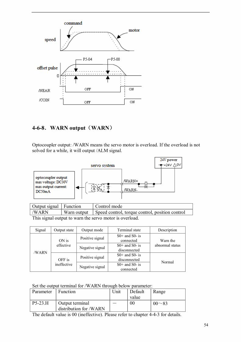
54
4-6-8.WARN output(WARN)
Optocoupler output: /WARN means the servo motor is overload. If the overload is not solved for a while, it will output /ALM signal.
Output signal Function Control mode /WARN Warn output Speed control, torque control, position control This signal output to warn the servo motor is overload.
Signal Output state Output mode Terminal state Description
/WARN
ON is effective
Positive signal S0+ and S0- is connected Warn the
abnormal status Negative signal S0+ and S0- is disconnected
OFF is ineffective
Positive signal S0+ and S0- is disconnected Normal
Negative signal S0+ and S0- is connected
Set the output terminal for /WARN through below parameter: Parameter Function Unit Default
value Range
P5-23.H Output terminal distribution for /WARN
- 00 00~83
The default value is 00 (ineffective). Please refer to chapter 4-4-3 for details.

55
4-7. Smooth run This chapter will introduce the skills of making the motor running smoothly.
4-7-1.Smooth
The command pulse (certain frequency) can be filtered. Choose the filter type through below parameter: Parameter Function Unit Range Default
value Control mode
P2-01 Choose the filter of position command
- 0, 1 0 Position control
P2-01 Choice 0 First-order inertial filter 1 Smooth filter The filter time can be set through below parameter: Parameter Function Unit Range Default
value Control mode
P2-04 Time of position command filter
ms 0~100 0 Position control
P2-04 is valid for external pulse speed control. When the speed is controlled by external pulse, it is limited by P2-04.
4-7-2.Soft start
Soft start means the servo speed changed with acceleration/deceleration, but not suddenly changed. Parameter Function Unit Range Default
value Control mode
P3-05 Soft start time (acceleration time)
ms 0~65535 0 Speed control
P3-06 Soft start time (deceleration time)
ms 0~65535 0 Speed control
Set acceleration and deceleration time for speed command. When the speed command is ladder changed or internal speed is selected, soft start function can be used. (Please set to 0 for normal case) • P3-05∶ the time from stop to rate speed • P3-06∶ the time from rated speed to stop

56
4-8. Servo gain adjustment This chapter will introduce the skills of gain adjustment.
4-8-1.Gain setting
The gain of speed loop Parameter Function Unit Range Default
value Control mode
P1-00 Speed loop gain (Kp)
Hz 1~500 100 Speed, position control
P1-01 Speed loop integral time (Ki)
0.1ms 1~5000 400 Speed, position control
The larger the speed loop gain or the smaller the speed loop integral time; the higher the reponse of speed control. But it is restricted by mechanical features.
The gain of position loop Parameter Function Unit Range Default
value Control mode
P1-02 Position loop gain (Kp)
1/s 1~200 30 Position control
The larger the speed loop gain, the higher the reponse and the less the position offset. But it is restricted by mechanical features.

57
This gain is valid when zero clamp. In position control mode, servo will alarm when offset pulse is over the offset pulse limit. Parameter Function Unit Range Default
value Control mode
P5-05 Offset pulse limit
256 command pulse
0~65535 1000 Speed control
P5-05=0, it will not check the value of offset pulse. Set the offset pulse voltage which can test the position offset pulse overflow alarm (E-10).
Position loop gain (P1-02) can not be set too large. E-10 will appear when the machine is running very fast. If the parameter value is too large, it is difficult to test the alarm.
4-8-2.Proportion action(P-CON)
Input signal /P-CON is the switch for P/PI of speed loop. P: proportion control, this mode is proportion action command. PI: proportion&integral control.
Proportion action command Set the input terminal for /P-CON through below parameter: Parameter Function Unit Range Default
value Control mode
P5-11.L Proportion action command, P/PI switch
- 00~C7
02 Speed, position control
The default value is 02, it means /P-CON will input from terminal SI2. Please refer to chapter 4-4-3 for details. The two cases to use proportion action command:
(1) The speed command is sent from upper device and run at the same time. The upper device will choose to run in P mode in special conditions. This way can delete the over range and shorten the adjustment time.
(2) When there is command offset in speed control, the servo will not stop even getting the zero speed command in PI mode. And the servo will run at low speed. If choose P mode, servo will stop at once.

58
4-8-3.Gain switching(G-SEL)
G-SEL signal can switch the gain when the servo is running. For example, the motor is running or stop, set first gain and second gain, switch to each other through G-SEL signal. Set the input terminal for /G-SEL through below parameter: Parameter Function Unit Range Default
value Control mode
P5-17.L Gain switching
- 00~C7 00 Position, speed control
The default value is 00 which means /G-SEL is invalid. In order to make the signal valid, please set P5-10.L to 01, then set P5-17.L. Please refer to chapter 4-4-2 for details. When the input terminal for /G-SEL is OFF, the first gain will be choosed (P1-00~P1-02), when it is ON, the second gain will be choosed (P1-04~P1-06). /G-SEL input signal Signal invalid Signal valid Speed loop gain P1-00 is valid P1-04 is valid Integral time P1-01 is valid P1-05 is valid Position loop gain P1-02 is valid P1-06 is valid

59
5 Use the operate panel This chapter describes the basic operation of the operate panel and the features it offers. All parameter settings and motor operations can be executed by simple, convenient operations.
5-1.Basic Operation This section provides information on the basic operation of the operate panel for setting operating conditions.
5-1-1. Functions of operate panel
The operate panel can be used for parameter settings, operating references, and status displays. 5-bit LED: Displaying parameter settings, status or alarm. Power LED POWER: The LED is on when the servo driver is powered on. Charge LED CHARGE: The LED is on when the main circiut is powered on. When
the power of main circiut is off, electric charges remain in the capacitors, and at this time DO NOT touch the servo.
This section provides information on the keys and their functions available from the initial displays.
Key Name Function STATUS/ESC Press: Status switch, status return INC Press: Increase the value; Press and hold: Increase the value continuously DEC Press: Decrease the value; Press and hold: Decrease the value continuously ENTER Press: Shift the editing digit; Press and hold: Enter a status, Enter
5-1-2. Basic Mode Switching
The operate panel can display the status, set parameter and run the command by switching the basic mode. The running status, auxiliary function, parameter setting, and monitoring are the basic modes. The modes switch as the below diagram by pressing STATUS/ESC.

60
Display mode: Monitor Function U- XXX: XXX means the number of the monitor function. Auxiliary Function FX-XX: The first X means group No., the last two X means the
member No. in the group. Parameter Setting PX-XX: The first X means group No., the last two X means the
member No. in the group. Alarm E-XXX: XXX means the alarm code.
5-2.Running status mode In running status mode, bit data and codes indicate the status of the servo driver.
Select the running status mode The servo will enter running status when power on. If not, press STATUS/ESC to enter.
The display content of running status mode The display contents are different in speed, torque, position control mode.
Speed and Torque Control Mode
A. Bit contents:
Bit Data Description
Speed Coincidence (/V-CMP)
Light when the motor actual speed and command speed is the same. Speed coincidence signal checking width: P5-03 (unit: rpm)
Torque Limit (/CLT) Light when actual torque exceeds preset value. Forward Torque Limit: P4-02 Reverse Torque Limit: P4-03
Rotation Detection Light when the motor speed exeeds the rotation detection speed.
Auxiliary function
Monitoring
Parameter setting
Running status
Power ON

61
(/TGON) Rotation Detection Speed Level: P5-02(Unit: rpm) Zero Clamp (/ZCLAMP) Light when zero clamp signal is ON.
Speed Limit (/VLT) Light when actual speed exceeds preset value. Speed Limit during Torque Control: P4-07
B. The code contents: Code Descrption
Standby Servo OFF (motor power OFF)
Run Servo ON (motor power ON)
Forward Run Prohibited P-OT is OFF. Please refer to 4-2-2 “Overtravel Limit”
Reverse Run Prohibited N-OT is OFF. Please refer to 4-2-2 “Overtravel Limit”
Position Control Mode
A. The bit contents:
Bit Data Description
Positioning Completed (/COIN)
Light when set position and actual position is the same. Positioning accomplishment width: P5-00 (unit: command pulse)
Near (/NEAR) Light when set position and actual position is the same. Near signal width: P5-04
Rotation Detection (/TGON)
Light when the motor speed exeeds the rotation detection speed. Rotation detection speed: P5-02(unit: rpm)
B. The code contents: Code Descrption
Standby Servo OFF (motor power OFF)
Run Servo ON (motor power ON)
Forward Run Prohibited P-OT is OFF. Please refer to 4-2-2 “Overtravel Limit”
Reverse Run Prohibited N-OT is OFF. Please refer to 4-2-2 “Overtravel Limit”

62
5-3. Monitoring Mode The Monitoring Mode can be used to monitor the reference values, I/O signal status, and servo driver internal status. The monitor mode can be set when the motor is running.
Using the Monitor Mode Now we take the monitor code U-016 as an example. 1. Press the STATUS/ESC key to select the monitoring mode.
2. Press the INC or DEC key to select the monitor number U-016, and then press and hold ENTER to enter the monitor mode.
3. The value 0 is now displayed. It means the driver is normal.
4. Press ENTER, the monitor no. will increase 1. 5. Press STATUS/ESC key to return to the monitoring number switching state.
Display contents of Monitoring Mode Number Monitor Display Unit U-000 Actual speed of motor Rpm U-001 Input speed command Rpm U-002 Internal torque command % U-003 Rotate angle (mechenism angle) 0.1° U-004 Rotate angle (electrical angle) 0.1° U-005 Bus voltage V U-006 Module temperature 0.1 U-007 Input command pulse speed Rpm U-008 Offset command
pulse (0000~FFFF)*1 Command
pulse U-009 (0000~FFFF)*FFFF U-010 Rotate angle (encoder
value) (0000~FFFF)*1 encoder pulse U-011 (0000~FFFF)*FFFF
U-012 Pulse value of input command
(0000~FFFF)*1 Pulse command U-013 (0000~FFFF)*FFFF
U-014 Pulse value of feedback command
(0000~FFFF)*1 Pulse command U-015 (0000~FFFF)*FFFF
U-016 Current position (Accumulated)
(0000~FFFF)*1 encoder pulse U-017 (0000~FFFF)*FFFF U-018 Current, 1-bit decimal 0.1A U-019 Analog input V-REF 0.01V U-020 Analog input T-REF 0.01V U-021 I/O signals status U-022 I/O terminals status
U-021 displays I/O signals status The following diagram describes the input and output signals status displayed in U-021.
Diagram 1 Diagram 2

63
In diagram 1, LED4 and LED5 stand for input signals status, and LED1 and LED2 stand for output signals status. In diagram 2 there shows the segment No. of each LED.
Input signals status
LED segment no.
Description Modbus address
LED segment no.
Description Modbus address
LED4_0 /SPD-A internal set speed selection
Ox0808 LED5_0 /S-ON servo signal 0x0800
LED4_1 /SPD-B internal set speed selection
0x0809 LED5_1 /P-CON proportion action command
0x0801
LED4_2 /C-SEL control mode selection
0x080A LED5_2 /P-OT forward prohibit
0x0802
LED4_3 /ZCLAMP zero clamp
0x080B LED5_3 /N-OT reverse prohibit 0x0803
LED4_4 Undefined 0x080C LED5_4 /ALM-RST clear the alarm
0x0804
LED4_5 /G-SEL switch the gain
0x080D LED5_5 /P-CL external torque limit at forward side
0x0805
LED4_6 /CLR clear the pulse 0x080E LED5_6 /N-CL external torque limit at reverse side
0x0806
LED5_7 /SPD-D internal set speed selection
0x0807
Output signals status
LED segment no.
Description Modbus address
LED segment no.
Description Modbus address
LED1_0 /NEAR near 0x081A LED2_0 /COIN positioning completed
0x0812
LED1_1 /ALM alarm output
0x081B LED2_1 /V-CMP speed synchronization checking
0x0813
LED2_2 /TGON rotate checking 0x0814 LED2_3 /S-RDY ready 0x0815 LED2_4 /CLT torque limit 0x0816 LED2_5 /VLT speed limit checking 0x0817 LED2_6 /BK brake lock 0x0818 LED2_7 /WARN warn 0x0819
Note: the signal state read through Modbus communication: 0 is OFF, 1 is ON.
U-022 displays I/O terminals status The following diagram describes the input and output terminals status:
Diagram 1 Diagram 2 In diagram 1, LED5 stands for input signals status, and LED2 stands for output signals status. In diagram 2 there shows the segment No. of each LED.
Input terminals Output terminals Segment Description Segment Description LED5_0 Input status of SI1 LED2_0 Output status of SO1 LED5_1 Input status of SI2 LED2_1 Output status of SO2

64
LED5_2 Input status of SI3 LED2_2 Output status of SO3 LED5_3 Input status of SI4 LED5_4 Input status of SI5 LED5_5 Input status of SI6 LED5_6 Input status of SI7
5-4.Auxiliary Function Use the operate panel to do application in auxiliary function mode.
Group No. Content F0-** Check system information, display the system code and data F1-** Auxiliary run mode, display the auxiliary run command and result F2-** Set the motor code F3-** Check the alarm information, clear the alarm F4-00 Reset parameters to default F5-00 External communication monitoring
5-4-1.Check System Infomation Press STATUS/ESC to switch to the auxiliary function mode. Set the group No. to 0 to check system information. Press INC or DEC key to select different No., and press and hold ENTER key to check current information. Press STATUS/ESC key to return. The following table describes the meaning of each No. Function No. Description Function No. Description F0-00 Motor Code F0-01 Servo Series F0-02 Servo Model F0-03 Produce Date: Year F0-04 Produce Date: Month day F0-05 Software version 1 F0-06 Software Version 2 F0-07 Hardware Version
5-4-2. Auxiliary Run Mode Press the STATUS/ESC key to select the auxiliary function mode. Set the group No. to 1. Press INC or DEC key to select different No., and press and hold ENTER key to use current function. Press STATUS/ESC key to return.
1. Jog (F1-00)
Make sure that the motor shaft is not connected to the machine before jogging! Press ENTER to power on the motor (servo on). Press INC for forward jogging, press DEC for reverse jogging. Press STATUS/ESC key to power off the motor (servo off), and press STATUS/ESC key again to return.
4 different states of jogging: State Panel Display State Panel Display
Idle
Forward Jogging
Servo ON
Reverse Jogging

65
2. Test run (F1-01)
Make sure that the motor shaft is not connected to the machine before test run! When servo driver is connected with non-original encoder line or power line, enter test run first to ensure that the encoder line or power line is connected correctly. LED will show 0 and shine after entering the test run. User must set the voltage (unit: %). Do not set it too large, recommended value is 20. Press ENTER to start the motor. The servo system will run forward (counterclockwise at shaft side), the shaft is rotate with certain speed, voltage. If the motor doesn’t rotate, please increase the voltage. If the wiring is wrong, the motor will run reverse and lock at certain angle. Please stop the servo system and find the problem. Press STATUS/ESC to exit.
3. Current Offset Auto-Adjustment (F1-02) When the servo driver has finsied the self-update, or the motor does not run smoothly for long time, the current offset auto-adjustment is recommended. Select F1-02 and enter current offset auto-adjustment function, and the panel displays “rEF”. Press ENTER key to start current offset auto-adjustment, and the panel displays blinking “rEF”. About 5 seconds later auto-adjustment is finished, and the panel displays “donE” to inform that the function is already finished. Press STATUS/ESC key to return.
4. Speed command offset auto-adjustment (F1-03) Select F1-03 and enter speed command offset auto-adjustment function, and the panel displays “rEF_o”. Press ENTER key to start speed command offset auto-adjustment, and the panel displays blinking “rEF_o”. About 1 second later, auto-adjustment is finished, and the panel displays “donE” to inform that the function is already finished. Press STATUS/ESC key to return.
5. Torque command offset Auto-Adjustment (F1-04) Select F1-04 and enter torque command offset auto-adjustment function, and the panel displays “rEF_o”. Press ENTER key to start torque command offset auto-adjustment, and the panel displays blinking “rEF_o”. About 1 second later, auto-adjustment is finished, and the panel displays “donE” to inform that the function is already finished. Press STATUS/ESC key to return.
6. Forced Servo enables (F1-05) 0: Cancel forced servo enables 1: Forced servo enables

66
5-4-3.Check Alarm Information The following steps show how to check alarm information. 1. Press STATUS/ESC key to select Auxiliary Function mode. 2. Press INC or DEC key to set group No. to 3, and press ENTER. 3. Press INC, DEC or ENTER key to modify the alarm No. 4. Press ENTER key to display corresponding alarm information. Member No. Description Unit Modbus
address F3-00 Current alarm code ※1 0x0716 F3-01 Current warn code ※2 0x0717 F3-02 Alarm/warn code 1 when alarm 0x0718 F3-03 U phase current when alarm A 0x0719 F3-04 V phase current when alarm A 0x071A F3-05 DC bus-voltage when alarm V 0x071B F3-06 IGBT module temperature when alarm 0x071C F3-07 Speed when alarm rpm 0x071D F3-08 Internal torque command when alarm % 0x071E F3-09 V-REF value when alarm V 0x071F F3-10 T-REF value when alarm V 0x0720 F3-11 Alarm/warn code 2 when alarm 0x0728 F3-12 Alarm/warn code 3 when alarm 0x0729 F3-13 Alarm/warn code 4 when alarm 0x072A F3-14 Alarm/warn code 5 when alarm 0x072B F3-15 Alarm/warn code 6 when alarm 0x072C F3-16 Alarm/warn code 7 when alarm 0x072D ※1: F3-00=0 indicates that there is no alarm. ※2: F3-01=0 indicates that there is no warn.
5-4-4. Reset Parameters to Default The following steps show how to reset parameters to default. 1. Close the servo enable (S-ON is OFF) 2. Press STATUS/ESC key to select Auxiliary Function. 3. Press INC or DEC key to set group No. to 4. 4. Choose F4-00. 5. Set the value to 1, press ENTER to confirm.
5-4-5. External monitoring Select F5-00 in auxiliary function, the panel displays “C-OUT” which means external monitoring mode, COM1 is effective, operate panel is ineffective. At this time user can debug the servo via PC. Press STATUS/ESC to exit.
5-5. Parameter Setting
Select or adjust the functions via parameter setting. Please refer to chapter 4-1 for parameters list.
The following steps show how to change a parameter. Check the permitted range of the parameters in chapter 4. The example below shows how to change parameter P3-09 from 2000 to 3000.

67
1. Press the STATUS/ESC key to select the parameter setting mode.
2. At this time the second LED is blinking, and press INC or DEC key to set the group No. to 3. Press ENTER key to confirm.
3. At this time the last two LED is blinking, and press INC or DEC key to set the member No. to 9. Press and hold ENTER key to confirm.
4. At this time the panel displays the value in P3-09, and numbers are blinking. Press INC to modify the value to 3000, and press ENTER to confirm.
The parameter in P3-09 in changed from 2000 to 3000. Repeat steps 2 to 4 to change the parameter again. 5. Press STATUS/ESC key to return.
5-6. Alarm Alarm code will pop up (E-XXX) if there is error in servo. The alarm state is invisible when there is no error in servo. The alarm code is E-XXX or EEEEE (operate panel communication error). Press ENTER to reset the alarm. If the servo power is OFF caused by alarming, it no needs to reset the alarm. Note: please find out the alarm reason before reset the alarm.

68
6 Specification and dimension
This chapter will introduce the specification and dimension of MS series servo motor and DS3 series servo drive.
6-1. Servo motor
6-1-1. Servo motor specification Please refer to this chapter when selecting the servo drive.
Volge level 220V
Motor MS- 80ST-M02430-20P7 110ST-M06030-21P8 130ST-M10015-21P5 Rated power(KW) 0.75 1.8 1.5 Rated current (A) 3.0 6.0 6.0
Rated speed (rpm) 3000 3000 1500 Rated torque (N·m) 2.39 6 10 Peak torque (N·m) 7.1 18 25 Back EMF constant
(V/krpm) 48 60 103
Torque coefficient(N·m/A) 0.8 1.0 1.67
Rotor inertia (Kg·m2) 0.24×10⁻³ 0.76×10⁻³ 1.94×10⁻³ Winding resistor (Ω) 2.88 0.776 1.34
Winding inductance (mH) 6.4 2.68 5.07
Electrical time constant (ms) 2.22 3.45 3.78
Weight (kg) 2.86 6.7 11.5 Encoder (ppr) 2500
Pole-pairs 4 Motor insulated level Class B (130)
Protection level IP65
Ambient Temperature -20~+50 Humidity Related humidity <90% (no condensation)
80 series motor winding socket
Motor winding socket Winding lead wire U V W PE Socket no. 1 3 2 4
80 series motor encoder socket Signal wire 5V 0V B+ Z- U+ Z+ U- A+ V+ W+ V- A- B- W- PE
Socket no. 2 3 4 5 6 7 8 9 10 11 12 13 14 15 1
110, 130 series motor winding socket
Motor winding socket Winding lead wire U V W PE Socket no. 2 3 4 1

69
110, 130 series motor encoder socket Signal wire 5V 0V A+ B+ Z+ A- B- Z- U+ V+ W+ U- V- W- PE
Socket no. 2 3 4 5 6 7 8 9 10 11 12 13 14 15 1
6-1-2. Torque-Speed Feature A: continuous using area B: repeated using area MS-80ST-M02430-20P7
MS-110ST-M06030-21P8
MS-130ST-M10015-21P5

70
6-1-3. Servo motor dimensions MS-80ST-M02430-20P7 Unit: mm
110, 130 series motor Unit: mm
Type LA LB LC LD LE LF LG LZ S MS-110ST-M0603-21P8
217 55 5 12 95 110 130 9 19
MS-130ST-M1001-21P5
217 57 5 14 110 130 145 9 22
6-2. Servo drivers This section introduces the specification and dimension of servo drive.
6-2-1. General specification Servo drive type DS3-20P7 DS3-21P8 DS3-21P5
Suitable motor 80ST-M02430-20P7 110ST-M06030
-21P8
130ST-M10015
-21P5
Speed (rpm) Rated 3000/max 4000 Rated 1500/max 2000 Suitable encoder Incremental encoder 2500 ppr
Max suitable motor capacity (kW) 1.8
Continuous output current (A rms) 6
Max output current (A rms) 18 Allowable regenerative frequency
(time/minute) 31

71
Input power 3-phase or single phase AC200~240V, 50/60Hz
Control mode 3-phase full-wave rectifier IGBT , PWM control, sine-wave current dirve
Using
Temperature 0 ~ +50 /-20 ~ +85
Humidity Below 90% RH (no condensation) Vibration /impact
resistance 4.9m/s2 / 19.6m/s2
Structure Base installation
6-2-2. Performance specification Servo drive type DS3-21P8, DS3-20P7, DS3-21P5
Speed torque control mode
Performance
Speed control range 1: 4000 (the lower limit of speed control range, not stop at rated load torque)
Speed change
rate
Load change rate 0~100% load: below ±0.01% (rated speed)
Voltage change rate Rated voltage ±10% : 0% (rated speed)
Temperature change rate 20±25: below ±0.1% (rated speed)
Frequency feature 250Hz (JL≤JM) Soft start time 0~65535ms (set acceleration, deceleration individually)
Input signal
Speed command
Command voltage
DC±10V
Input resistor About 13KΩ
Torque command
Command voltage
DC±10V
Input resistor About 13KΩ
Position control mode
Performance
Feedforward compensation 0~100% (resolution is 1%)
Positioning finished width 0~250 command unit (resolution is 1 command unit)
Input signal
Com
mand
pulse Input pulse
type Sign+pulse, A/B orthogonal pulse
Input pulse state Line drive (+5V), collector (+5V, +12V, +24V)
Input pulse frequency Bus drive 500kbps, transistor open circuit 200 kbps
Control signal Clear signal (/CLR) Internal open
collector power supply
+5V (internal 150Ω resistor)
I/O signal
Position output
Output mode Phase A, B, Z: bus differential drive output Z phase transistor OC output
Frequency division ratio 1:1
Input signal
External input 7 Changeable signal
distribution /S-ON, /P-CON, /P-OT, /N-OT, /ALM-RST, /PCL, /NCL, /SPD-D, /SPD-A, /SPD-B, /C-SEL, /ZCLAMP, /CLR, /G-SEL
Output signal
External output 3 Changeable signal
distribution /COIN, /V-CMP, /TGON, /S-RDY, /CLT, /VLT, /BK, /WARN, /NEAR, /ALM
Built-in function
Dynamic brake (DB) Valid when power is OFF/servo alarm/servo OFF/over-range Regeneration External regenerative resistor
Over range(OT)protection P-OT, N-OT action, DB stop, deceleration stop or inertia stop Electronic gear 0.01≤ B/A≤100
Protection
Program error, parameter error, overvoltage, undervoltage, regeneration error, overtemperature, overcurrent, overspeed, analog input error, position offset overflow, output shorting, current error, encoder cut, encoder error, overload, power off when running, write parameter error…
LED display Charge, power supply, 7-segment LED ×5 (built-in digital operate) COM1 Connect device RS232, connect to PC
Serial Baud rate 19200; data bit 8; stop bit 1; communication protocol:

72
communication
parameters ModubsRTU slave; Modbus station No.1 Functions Debug online
COM2
Connect device RS232, RS485, connect to PLC, HMI, PC and other devices Serial
parameters Serial parameter can be set; communication protocol: ModbusRTU slave; Modbus station No. can be set
Functions State display, user constant setting, monitor display, alarm display, alarm display, special control, online debug
6-2-3. Servo drive dimensions Unit: mm
152
1212
186
186
5375
67
67
177.
7
4
R2.5
4.1
4.2

73
7 Alarm Information
This chapter describes the alarm information of DS3 series servo drives.
Alarm Code
Description Reason Solution
E-001 Program damage program self-test failed Re-download the program or contact Xinje or an authorized distributor
E-002 Parameter damage Parameter self-test failed
Restart the drive to reset the parameters. If it occurs for many times please contact Xinje or an authorized distributor
E-003 Bus over-voltage
Power grid is over votage or need a regenerative resistor; the regenerative resistor damage or its value is too large
Check the power grid; connect and check the regenerative resistor
E-004 Bus under voltage
Power grid is under votage Check the power grid
E-005 Regenerative resistor error
Regenerative resistor is ineffective
Check the connection of regenerative resistor
E-006 Module over temperature
Run with large load for long time
Reduce the load, and enhance the cooling system, or check if the fan is revolving when motor is ON; cool down the ambient temperature
E-007 Over current UVW of drive is short circiut or the motor is error
Replace the damaged motor; check the UVW wiring.
E-008 Over speed Motor speed is too fast, motor UVW connection is error
Check if there is other device that make motor revolve too fast; check the UVW wiring.
E-009 Analog input error Input voltage error when 2-channe analog zero calibrating
Input correct voltage when zero calibration for analog
E-010 Position offset too large
The difference between set position and actual position exceeds the limit value
Check if the motor stalled, decrease the set position speed, increase offset pulse limit value P5-05
E-011 Motor UVW is short circiut
External is short circuit when fist self-test
Check the UVW wiring of motor, or replace the damaged motor
E-012 Motor UVW current error
Current collection circuit error
Check the UVW wiring of motor, or replace the damaged drive
E-013 Encoder UVW wire cut off
Encoder wiring error, encoder broken, encoder is not connected
Check the wiring of encoder, and re-connect the encoder after power-off, or replace the damaged encoder

74
E-014 Encoder ABZ wire cut off
Encoder wiring error, encoder broken, encoder is not connected
Check the wiring of encoder, and re-connect the encoder after power-off, or replace the damaged encoder
E-015 Speed changes too fast (encoder feedback error)
The encoder wiring is error, or the encoder has interference
Check the wiring of encoder, or add shield layer for the encoder wire
E-016 Overload Run overload for long time
Reduce the overload running time, change a motor with larger rated power
E-017 Power supply is off when running
The power supply is off when running
Re-power on after the bus voltage is normal

Xinje Electronic Co., Ltd.
4th Floor Building 7,Originality Industry park, Liyuan Development Zone, Wuxi City, Jiangsu Province 214072
Tel: (510) 85166657
Fax: (510) 85111290
www.xinje.com