Embed Size (px)
Citation preview

141Make:
Beef up on robotic musculature.By Tod E. Kurt
You’ve seen them in robots and toys, or at least heard the distinctive zzt-zzt-zzt sound thataccompanies their movement. R/C servomotors,designed for use in radio-controlled hobby cars and planes, are a common tool for robotics, movie effects, and puppeteering. Servos don’t spin like normal motors, butinstead rotate and stop at a commanded posi-tion between 0 and 180 degrees. They’re oneof the easiest ways to add motion to a project, and there are many different kinds of servosto choose from. Servos can also be hacked to create high-quality, digitally controlled, variable-speedgearmotors, with a few simple modifications.In this article I’ll explain the basics of how touse servos, and how to hack them to makecontinuous rotation servos as well.
Ph
otog
rap
hy b
y To
d K
urt
SERVO-MOTORS
»
M_140-147_Prmr_F2.indd 141M_140-147_Prmr_F2.indd 141 7/7/09 11:41:39 AM7/7/09 11:41:39 AM

makezine.com/19/primer
142 Make: Volume 19
SERVOMOTORS
Illu
stra
tion
s by
Dam
ien
Sco
gin
UNDERSTANDING SERVOSR/C servomotors (or just “servos”)are packed with technology, including a DC motor, gear train, sensor, and control electronics. They are a kind of servomechanism. Servomechanisms use a feedback control loop to adjust how a mechanism functions. One example of a servomechanism is a thermostat-controlled heating system. The temperature-sensing thermostatis the feedback-providing sensor, and the heating element is the output. The heater gets turned on and off basedon the temperature sensing. For R/C servos, the sensor input is a potentiometer (or “pot” for short) that’s used to measure the amount of rotation from the output motor. Control electronics read the electrical resis-tance of the pot and adjust the speed and direction of the motor to spin ittoward the commanded position. Figure A shows an exploded view of a standard servo and the workings of the servo’s closed feedback control loop.
SELECTING SERVOSServos come in a variety of shapes and sizes (Figure B). The most common class of servo is the standard servo (1). The smallest servos are the micro class (2, 3), and the largest are the high-torque/winch class (4). All of these have the same 3-wire control, so it’s easy to move to a bigger or smaller servo as your needs change. Besides their dimensions and weight, servos are characterized by two main attributes: torque and speed, deter-mined by the gearing and the motor in the servo. The torque is essentially the strength of the servo. A standard servo torque value is 5.5kg/cm (75oz/in) when
A
B4
3
12
Motor
Control electronics
Control input
Gear train
Pot
Driveshaft
CONTROL SEQUENCE
Read position (pot)
Make motion (motor)
Drive motor(controlelectronics)
Couplerotation(gear train)
M_140-147_Prmr_F2.indd 142M_140-147_Prmr_F2.indd 142 7/7/09 11:43:00 AM7/7/09 11:43:00 AM
143Make:
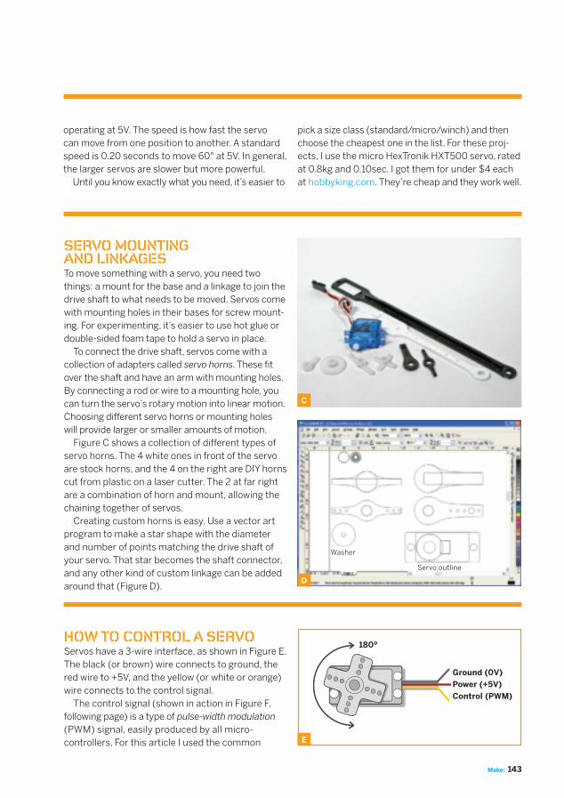
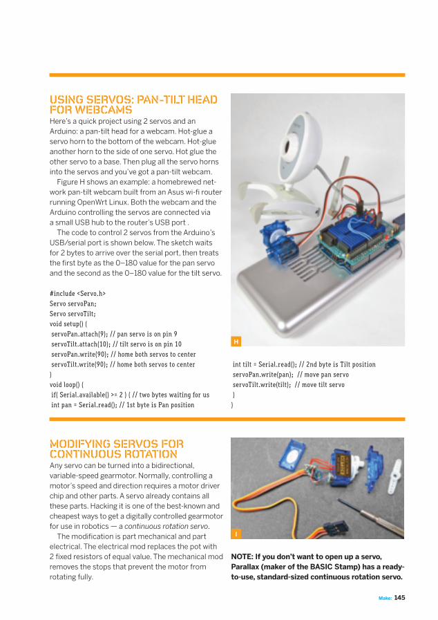
SERVO MOUNTING AND LINKAGESTo move something with a servo, you need two things: a mount for the base and a linkage to join the drive shaft to what needs to be moved. Servos come with mounting holes in their bases for screw mount-ing. For experimenting, it’s easier to use hot glue or double-sided foam tape to hold a servo in place. To connect the drive shaft, servos come with a collection of adapters called servo horns. These fit over the shaft and have an arm with mounting holes. By connecting a rod or wire to a mounting hole, you can turn the servo’s rotary motion into linear motion. Choosing different servo horns or mounting holes will provide larger or smaller amounts of motion. Figure C shows a collection of different types of servo horns. The 4 white ones in front of the servo are stock horns, and the 4 on the right are DIY horns cut from plastic on a laser cutter. The 2 at far right are a combination of horn and mount, allowing the chaining together of servos. Creating custom horns is easy. Use a vector art program to make a star shape with the diameter and number of points matching the drive shaft of your servo. That star becomes the shaft connector, and any other kind of custom linkage can be added around that (Figure D).
C
D
operating at 5V. The speed is how fast the servo can move from one position to another. A standard speed is 0.20 seconds to move 60° at 5V. In general, the larger servos are slower but more powerful. Until you know exactly what you need, it’s easier to
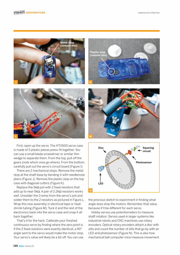
HOW TO CONTROL A SERVOServos have a 3-wire interface, as shown in Figure E. The black (or brown) wire connects to ground, the red wire to +5V, and the yellow (or white or orange) wire connects to the control signal. The control signal (shown in action in Figure F, following page) is a type of pulse-width modulation (PWM) signal, easily produced by all micro-controllers. For this article I used the common E
Ground (0V)
Power (+5V)
Control (PWM)
180º
pick a size class (standard/micro/winch) and then choose the cheapest one in the list. For these proj-ects, I use the micro HexTronik HXT500 servo, rated at 0.8kg and 0.10sec. I got them for under $4 each at hobbyking.com. They’re cheap and they work well.
Washer
Servo outline
M_140-147_Prmr_F2.indd 143M_140-147_Prmr_F2.indd 143 7/7/09 11:43:25 AM7/7/09 11:43:25 AM

makezine.com/19/primer
144 Make: Volume 19
SERVOMOTORS
Arduino microcontroller. The HIGH part of the pulse lasts between 1 and 2 milliseconds (ms), equal to 1,000 to 2,000 micro-seconds (μs). At 1,000μs, the servo will rotate to its full anti-clockwise position. At 2,000μs, it will rotate to its full clockwise position. Some servos accept shorter or longer pulses and have a correspondingly larger rotational range. The LOW part of the control pulse lasts for 20milliseconds. Every 20ms (50 times per second), the HIGH pulse must be received again or the servo will de-energize and not hold its position. This is useful if you want your project to “go limp.” Below is a complete Arduino sketch that willcontinually position the servo at its midpoint.Controlling a servo is pretty easy.
int servoPin = 9;int servoPosition = 1500; // position in microsecondsvoid setup() { pinMode(servoPin, OUTPUT);}void loop() { digitalWrite(servoPin, HIGH); delayMicroseconds(servoPosition); digitalWrite(servoPin, LOW); delay(20); // wait 20 milliseconds}
Wire up the servo as in Figure G. Red and blackwires go to the Arduino’s 5V power and Gnd pins. The control wire goes to digital input/output pin 9.
The problem with this Arduino sketch is that it spends most of its time stuck in the delay com-mands. Fortunately, the Arduino’s built-in Servo library lets you control 2 servos (on pins 9 and 10) using its built-in timers, and frees up your code to do other things. The same sketch using the library would be:
#include <Servo.h>Servo myservo;void setup() { myservo.attach(9); // servo is on pin 9 like before myservo.write(90); // set servo to 90 degree position}void loop() { // free to do anything, our servo is still being driven for us}
G
F
0 degrees
1,000 microseconds 1,250 microseconds 2,000 microseconds
High High High
Low Low Low
45 degrees 180 degrees
M_140-147_Prmr_F2.indd 144M_140-147_Prmr_F2.indd 144 7/7/09 11:44:04 AM7/7/09 11:44:04 AM
145Make:
USING SERVOS: PAN-TILT HEAD FOR WEBCAMSHere’s a quick project using 2 servos and an Arduino: a pan-tilt head for a webcam. Hot-glue a servo horn to the bottom of the webcam. Hot-glue another horn to the side of one servo. Hot glue the other servo to a base. Then plug all the servo horns into the servos and you’ve got a pan-tilt webcam. Figure H shows an example: a homebrewed net-work pan-tilt webcam built from an Asus wi-fi router running OpenWrt Linux. Both the webcam and the Arduino controlling the servos are connected viaa small USB hub to the router’s USB port . The code to control 2 servos from the Arduino’s USB/serial port is shown below. The sketch waits for 2 bytes to arrive over the serial port, then treats the first byte as the 0–180 value for the pan servo and the second as the 0–180 value for the tilt servo.
#include <Servo.h>Servo servoPan;Servo servoTilt;void setup() { servoPan.attach(9); // pan servo is on pin 9 servoTilt.attach(10); // tilt servo is on pin 10 servoPan.write(90); // home both servos to center servoTilt.write(90); // home both servos to center}void loop() { if( Serial.available() >= 2 ) { // two bytes waiting for us int pan = Serial.read(); // 1st byte is Pan position
H
int tilt = Serial.read(); // 2nd byte is Tilt position servoPan.write(pan); // move pan servo servoTilt.write(tilt); // move tilt servo }}
MODIFYING SERVOS FOR CONTINUOUS ROTATIONAny servo can be turned into a bidirectional, variable-speed gearmotor. Normally, controlling a motor’s speed and direction requires a motor driver chip and other parts. A servo already contains all these parts. Hacking it is one of the best-known and cheapest ways to get a digitally controlled gearmotorfor use in robotics — a continuous rotation servo. The modification is part mechanical and part electrical. The electrical mod replaces the pot with2 fixed resistors of equal value. The mechanical mod removes the stops that prevent the motor from rotating fully.
I
NOTE: If you don’t want to open up a servo,Parallax (maker of the BASIC Stamp) has a ready-to-use, standard-sized continuous rotation servo.
M_140-147_Prmr_F2.indd 145M_140-147_Prmr_F2.indd 145 7/7/09 11:44:47 AM7/7/09 11:44:47 AM
makezine.com/19/primer
146 Make: Volume 19
SERVOMOTORS
First, open up the servo. The HTX500 servo case is made of 3 plastic pieces press-fit together. You can use a small blade screwdriver or similar thin wedge to separate them. From the top, pull off the gears (note which ones go where). From the bottom, carefully pull out the servo’s circuit board (Figure I). There are 2 mechanical stops. Remove the metal stop at the shaft base by bending it with needlenose pliers (Figure J). Remove the plastic stop on the top case with diagonal cutters (Figure K). Replace the 5kΩ pot with 2 fixed resistors that add up to near 5kΩ. A pair of 2.2kΩ resistors works well. Unsolder the 3 wires from the servo’s pot and solder them to the 2 resistors as pictured in Figure L.Wrap this new assembly in electrical tape or heat-shrink tubing (Figure M). Tuck it and the rest of the electronics back into the servo case and snap it all back together. That’s it for the hack. Calibrate your finished continuous servo by finding where the zero point is. If the 2 fixed resistors were exactly identical, a 90° angle sent to the servo would make the motor stop. Your servo’s value will likely be a bit off. You can use
J
L
K
M
the previous sketch to experiment in finding what angle does stop the motors. Remember that value, because it’ll be different for each servo. Hobby servos use potentiometers to measure shaft rotation. Servos used in larger systems like industrial robots and CNC machines use rotary encoders. Optical rotary encoders attach a disc with slits and count the number of slits that go by with anLED and photosensor (Figure N). This is also how mechanical ball computer mice measure movement.
Metal stop(remove this)
Plastic stop(remove this)
N
LED
Disc Squaring circuit
Photosensor
M_140-147_Prmr_F2.indd 146M_140-147_Prmr_F2.indd 146 7/7/09 11:45:25 AM7/7/09 11:45:25 AM
147Make:
Tod E. Kurt (todbot.com/blog) is co-founder of ThingM, makers of the BlinkM Smart LED (blinkm.thingm.com), and author of Hacking Roomba (hackingroomba.com), an introductory robotics course disguised as a set of vacuum cleaner hacks.
RESOURCES» Hobby People (hobbypeople.net) is a good
U.S.-based vendor of servos.» HobbyKing (hobbyking.com), formerly HobbyCity,
is a China-based servo vendor with a huge selection.» Adafruit (adafruit.com) carries Arduino and
Boarduino microcontrollers, and Parallaxcontinuous servos.
» Trossen Robotics (trossenrobotics.com) carriesParallax continuous servos and many other neat robot things.
» Oomlout SERB robot (oomlout.com/serb.html)is an open source robot base that uses continuous servos.
» Servo hacks on Instructables (instructables.com): Do a search for “servo” to see many more servo projects.
O
P
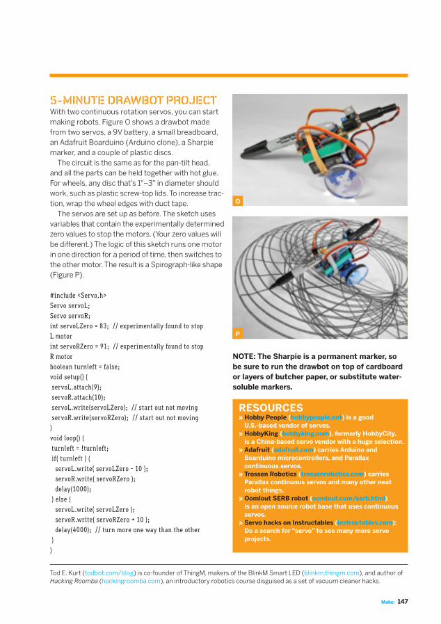
5-MINUTE DRAWBOT PROJECTWith two continuous rotation servos, you can start making robots. Figure O shows a drawbot made from two servos, a 9V battery, a small breadboard, an Adafruit Boarduino (Arduino clone), a Sharpie marker, and a couple of plastic discs. The circuit is the same as for the pan-tilt head, and all the parts can be held together with hot glue. For wheels, any disc that’s 1"–3" in diameter should work, such as plastic screw-top lids. To increase trac-tion, wrap the wheel edges with duct tape. The servos are set up as before. The sketch uses variables that contain the experimentally determined zero values to stop the motors. (Your zero values will be different.) The logic of this sketch runs one motor in one direction for a period of time, then switches to the other motor. The result is a Spirograph-like shape (Figure P).
#include <Servo.h>Servo servoL;Servo servoR;int servoLZero = 83; // experimentally found to stop L motorint servoRZero = 91; // experimentally found to stop R motorboolean turnleft = false;void setup() { servoL.attach(9); servoR.attach(10); servoL.write(servoLZero); // start out not moving servoR.write(servoRZero); // start out not moving}void loop() { turnleft = !turnleft; if( turnleft ) { servoL.write( servoLZero - 10 ); servoR.write( servoRZero ); delay(1000); } else { servoL.write( servoLZero ); servoR.write( servoRZero + 10 ); delay(4000); // turn more one way than the other }}
NOTE: The Sharpie is a permanent marker, so be sure to run the drawbot on top of cardboard or layers of butcher paper, or substitute water-soluble markers.
M_140-147_Prmr_F2.indd 147M_140-147_Prmr_F2.indd 147 7/8/09 12:29:05 PM7/8/09 12:29:05 PM


![New FA Equipment for Beginners(Servos) IND.ppt [互換モード] · 2016. 9. 29. · Motor servo DC memerlukan pemeriksaan dan perawatan sikat penyearah arus. Motor servo DC tidak](https://img.pdfslide.net/doc/110x75/607602337f77c524794d9ff2/new-fa-equipment-for-beginnersservos-indppt-fff-2016-9-29.jpg)


![FA Equipment for Beginners(Servos) ENG.ppt [互換モード] · DC servo motors cannot be used in applications requiring clean environments as they Types of servo motors There are](https://img.pdfslide.net/doc/110x75/5e28aa30f85efc428229dae2/fa-equipment-for-beginnersservos-engppt-fff-dc-servo-motors-cannot.jpg)