Embed Size (px)
Citation preview
MAQUET
SERVO-s Ventilator System
Service Manual
CRITICAL CARE
V
r
0.M
5500
/
f
i

Important SERVO-s Ventilator System
Notes
1 - 2 Service Manual Revision 01
SERVO-s Ventilator System Contents
Contents
1. Important
2. Introduction
3. Description of functions
4. Disassembling and assembling
5. Service procedures
6. Troubleshooting
7. Preventive maintenance
8. Index
9. Diagrams
1
7
Revision 01 Service Manual 1-3
Important SERVO-s Ventilator System
1
ImportantGeneral
. Service documentation for the SERVO-s
Ventilator System consists of:- User's manual. The User's manual is an
indispensable complement to the ServiceManual for proper servicing.
- Service Manual
- Installation Instructions
- Spare Parts information
- Documentation for all optional equipmentincluded in the SERVO-s System is alsoavailable.
. The SERVO-s Ventilator System is referred to asthe SERVO-s throughout this manual.
. There are two serial number labels on the unit:
- One label is attached to the Patient Unit close
to the supply gas inlets. The serial numberstated on this label is the ID number of the
Patient Unit. The serial number is also stored in
the SW memory as the 'System ID'.- One label is attached to the rear side of the
User Interface close to the On/Off switch. The
serial number stated on this label is the ID
number of the User Interface.
. System version number can be found in theStatus window on the User Interface. Make sure
that the version of the User's manual correspondsto the System version.
Text inside a box is used to highlight Importantinformation.
. In addition to the Important information givenhere and in the related documents (e. g. in theUser's manual), always pay attention to applicablelocal and national regulations.
. Responsibility for the safe functioning of theequipment reverts to the owner or user in allcases in which service or repair has been doneby a non-professional or by persons who are notemployed by or authorized by MAQUET, andwhen the equipment is used for other than itsintended purpose.
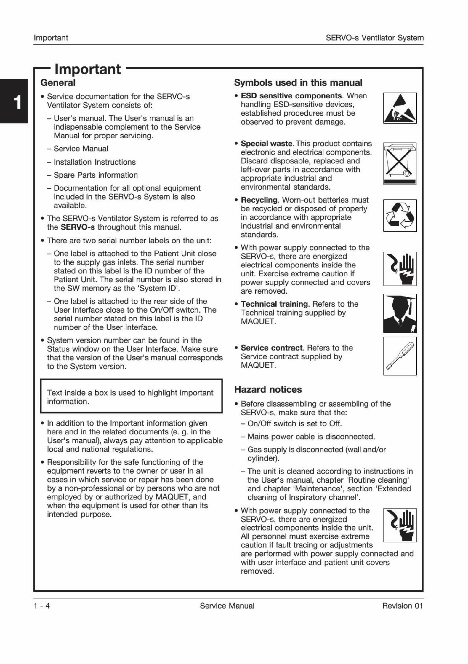
Symbols used in this manual. ESD sensitive components.
When
handling ESD-sensitive devices,established procedures must beobserved to prevent damage.
. Special waste. This product containselectronic and electrical components.Discard disposable, replaced andleft-over parts in accordance withappropriate industrial andenvironmental standards.
. Recycling. Worn-out batteries must
be recycled or disposed of properlyin accordance with appropriateindustrial and environmental
standards.
. With power supply connected to theSERVO-s, there are energizedelectrical components inside theunit. Exercise extreme caution if
power supply connected and coversare removed.
. Technical training. Refers to the
Technical training supplied byMAQUET.
. Service contract. Refers to the
Service contract supplied byMAQUET.
Hazard notices
. Before disassembling or assembling of theSERVO-s, make sure that the:
- On/Off switch is set to Off.
- Mains power cable is disconnected.
- Gas supply is disconnected (wall and/orcylinder).
- The unit is cleaned according to instructions inthe User's manual, chapter 'Routine cleaning'and chapter
'Maintenance', section 'Extended
cleaning of Inspiratory channel'.
. With power supply connected to theSERVO-s, there are energizedelectrical components inside the unit.All personnel must exercise extremecaution if fault tracing or adjustments
"
are performed with power supply connected andwith user interface and patient unit coversremoved.
1 -4 Service Manual Revision 01
SERVO-s Ventilator System Important
ImportantInstallation
. Only personnel trained and authorizedby MAQUET shall be permitted toinstall the SERVO-s. The installation
and handing-over procedures aredescribed in the 'SERVO-s Ventilator
System - Installation Instructions'.
Functional check
. After any installation, maintenance or service
intervention in the SERVO-s, perform a 'Pre-usecheck' according to instructions in the 'SERVO-sVentilator System - User's manual'.
Service
. The SERVO-s must be serviced at
regular intervals by personnel trainedand authorized by MAQUET.Any maintenance or service must benoted in a log book provided.
. It is recommended that maintenance
and service is done as a part of aservice contract with MAQUET.
. Preventive maintenance must be performed atleast once every year as long as the unit is notused more than normal. Normal operation isestimated to correspond to approx. 5.000 hoursof operation. Details are found in this ServiceManual, chapter 'Preventive maintenance'.
. The Battery modules shall be replaced after twoand a half years from their manufacturing date.
. The internal Lithium batteries (on PC 1771 andPC 1772) shall be replaced every five years.
. Worn-out batteries must be recycled ordisposed of properly in accordancewith appropriate industrial andenvironmental standards.
. This product contains electronic andelectrical components. Discarddisposable, replaced and left-overparts in accordance with appropriateindustrial and environmental standards.
. When working with ESD sensitivecomponents, always use a groundedwrist band and a grounded worksurface. Adequate service tools mustalways be used.
A
To the responsible service personnel
. The contents of this document are not binding.
If any significant difference is found between theproduct and this document, please contactMAQUET for further information.
. We reserve the right to modify products withoutamending this document or advising the user.
. Only personnel trained and authorizedby MAQUET shall be permitted toperform installation, service ormaintenance of the SERVO-s. OnlyMAQUET genuine spare parts must beused. PC boards (spare parts) must always bekept in a package for sensitive electronicdevices. MAQUET will not otherwise assume
responsibility for the materials used, the workperformed or any possible consequences ofsame.
. The device complies to standards and require-ments as stated in the 'SERVO-s Ventilator
System - User's manual'.
1
Revision 01 Service Manual 1 -5
Important SERVO-s Ventilator System
1
ImportantEnvironmental declaration
Purpose
This environmental declaration is for a SERVO-s
base unit.
Letters codes within brackets refers to the
Functional Block Diagram in chapter Diagrams.
Components with special environmentalconcern
Components listed below shall be disposed of inaccordance with appropriate industrial andenvironmental standards.
Printed circuit boards
. PC 1771 Control, including a Lithium battery (C)
. PC 1772 Monitoring, including Lithium battery (M)
. PC 1777 Panel (U)
. PC 1781 Pressure transducer, 2 each (T)
. PC 1784 Expiratory channel (F)
. PC 1785 Expiratory channel connector (E)
. PC 1786 Expiratory channel cassette (E)
. PC 1860 Main back-plane
. PC 1861 Pneumatic back-plane (I)
. PC 1862 DC/DC & Standard connectors (P)
. PC 1863 Power control (P)
Other electronics
. TFT assembly including backlight (U)
. Touch screen (U)
. 02 cell, containing Pb (I)
. Gas module Air, containing multiple PC boards (I)
. Gas module 02, containing multiple PC boards (I)
. AC/DC Converter, containing PC boards (P)
. Battery modules, Nickel Metalhydrlde (P)
. Expiratory cassette (E)
. Expiratory valve coil (E)
. Safety vaive pull magnet (I)
Construction materials
The construction materials used in SERVO-s in %
of the total weight.
Metal - total 72.5%
. Aluminium 70%
. Steel, zink, brass 2.5%
Polymeric material - total 8%
. PA (Polyamlde)
. POM (Poiyoxymethylene)
. 81 (Silicone)
. TPE (Thermoplastic elastomer)
. PUR (Polyurethane)
. ABS (Acrylicnltrilebutadienstyrene)
. EPDM (Ethylenepropylenedienemonomer)
. PTFE (Polytetrafluoroethylene)
. FPM (Fluororubber)
. NBR (Nitrilerubber)
. PP (Polypropylene)
. PVC (Polyvinyl chloride)
. PS (Polystyrene)
Electronics - total 19.5%
. Battery modules. Nickel Metalhydrlde
. Printed circuit boards, cables etc.
Others - very small amounts
. Sterile filter paper of glass fibre
1 -6 Service Manual Revision 01
SERVO-s Ventilator System Important
r ImportantArticles of consumption
1. Bacteria filter
2. Filters for the gas modules
3. Filter for the inspiration pressure transducer
4. Filter for the 0
2 cell
5. Nozzle units for the gas modules
6. Battery modules
7. Lithium batteries
8. Expiratory cassette
9. Expiratory cassette membrane
10. 02 cell
11. Backlight lamps.
Item 1: Consumption approximately 250 pcs/year.
Items 2-5: Changed approx. every 5.000 hours.
Items 6: Changed approx. every 12.500 hours.
Items 7: Changed approx. every 25.000 hours.
Items 8-11: Changed when needed.
Power consumption
The power consumption depends on the operatingmode and whether the internal batteries are beingfast or trickle charged.
Mode Fast charging Trickle charging
In operation
Standby
Off
70 W
65 W
35 W
38 W
33 W
6 W
Noise level
Less than 50 dBA.
Packing materials
The amounts of packing materials will varydepending on customer adaptation.
Materials for packing:
. Loading pallet. Fulfils the USA requirements7 CFR 319.40 May 25' 1995.
. Corrugated cardboard
. Shock-absorbing material of expanded poly-ethylene, EPE, or expanded polypropylene, EPP.
1
Revision 01 Service Manual 1 - 7
Important SERVO-s Ventilator System
Notes
1
1 - 8 Service Manual Revision 01
SERVO-s Ventilator System Introduction
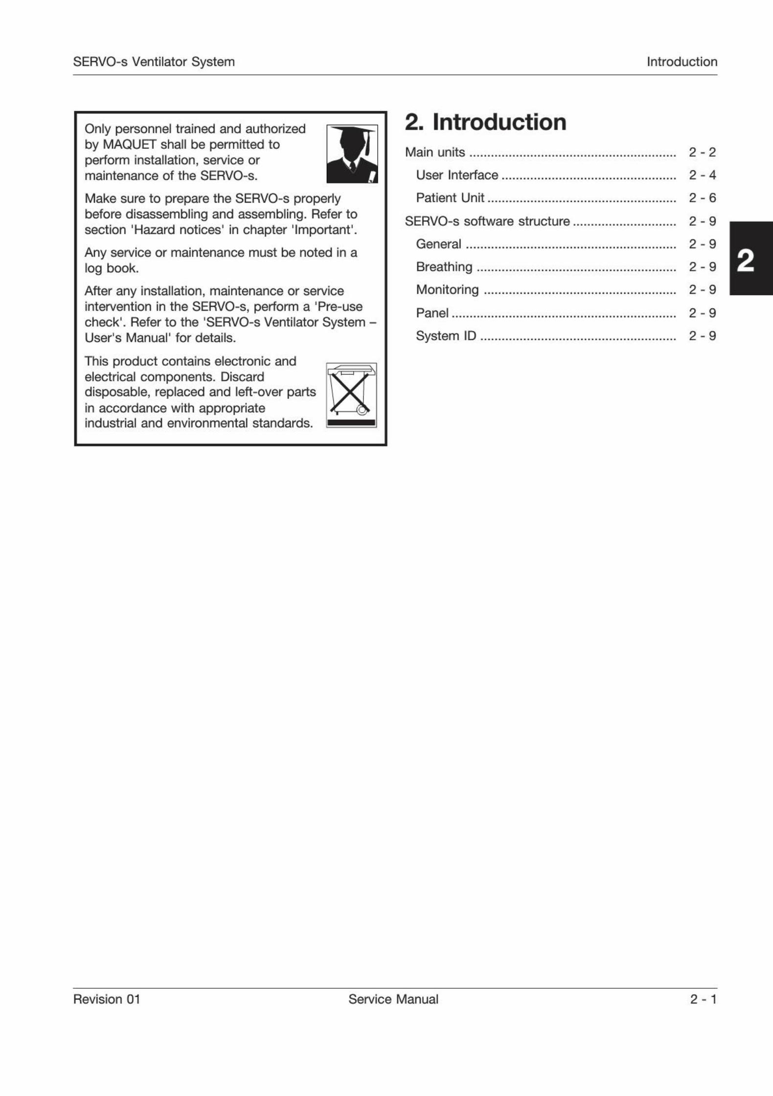
Only personnel trained and authorizedby MAQUET shall be permitted toperform installation, service ormaintenance of the SERVO-s.
Make sure to prepare the SERVO-s properlybefore disassembling and assembling. Refer tosection 'Hazard notices' in chapter 'Important'.
Any service or maintenance must be noted in alog book.
After any installation, maintenance or serviceintervention in the SERVO-s, perform a 'Pre-usecheck'
. Refer to the 'SERVO-s Ventilator System -User's Manual' for details.
This product contains electronic andelectrical components. Discarddisposable, replaced and left-over partsin accordance with appropriateindustrial and environmental standards.
2. Introduction
Main units 2-2
User Interface 2-4
Patient Unit 2 - 6
SERVO-s software structure 2 - 9
General 2 - 9
Breathing ,
Monitoring
Panel ,
2-9
2-9
2-9
System ID 2 - 9
Revision 01 Service Manual 2 - 1
Introduction SERVO-s Ventilator System
Main units
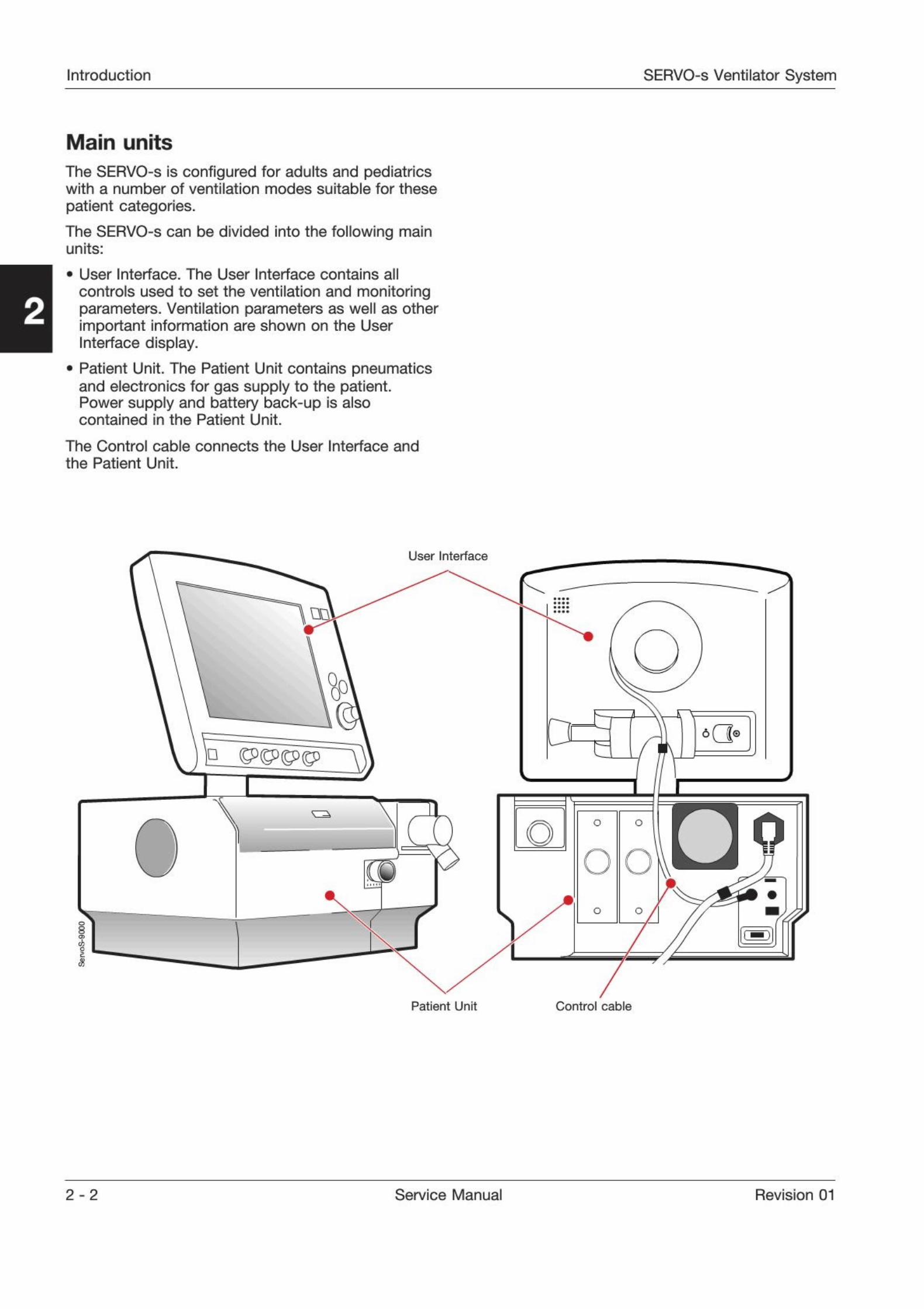
The SERVO-s is configured for adults and pediatricswith a number of ventilation modes suitable for these
patient categories.
The SERVO-s can be divided into the following mainunits:
. User Interface. The User Interface contains all
controls used to set the ventilation and monitoringparameters. Ventilation parameters as well as otherimportant information are shown on the UserInterface display.
. Patient Unit. The Patient Unit contains pneumatics
and electronics for gas supply to the patient.Power supply and battery back-up is alsocontained in the Patient Unit.
The Control cable connects the User Interface and
the Patient Unit.
User Interface
s
m
Patient Unit Control cable
2-2 Service Manual Revision 01
SERVO-s Ventilator System Introduction
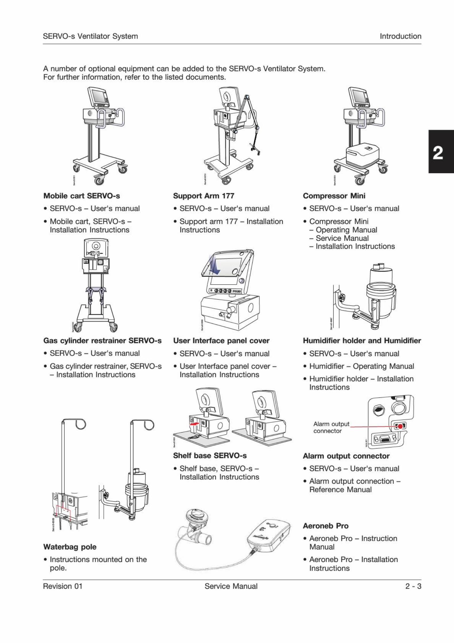
A number of optional equipment can be added to the SERVO-s Ventilator System.For further information, refer to the listed documents.
Mobile cart SERVO-s
. SERVO-s - User's manual
. Mobile cart, SERVO-s -
Installation Instructions
Support Arm 177
. SERVO-s - User's manual
. Support arm 177 - InstallationInstructions
O
3
C3T
0
Gas cylinder restrainer SERVO-s
. SERVO-s - User's manual
. Gas cylinder restrainer, SERVO-s
- Installation Instructions
User Interface panel cover
. SERVO-s - User's manual
. User Interface panel cover -Installation Instructions
ro 0
Shelf base SERVO-s
. Shelf base, SERVO-s -
Installation Instructions
Waterbag pole
. Instructions mounted on the
pole.
C TR
Compressor Mini
. SERVO-s - User's manual
. Compressor Mini- Operating Manual- Service Manual- Installation Instructions
Humidifier holder and Humidifier
. SERVO-s - User's manual
. Humidifier - Operating Manual
. Humidifier holder - Installation
Instructions
Alarm outputconnector
Alarm output connector
. SERVO-s - User's manual
. Alarm output connection -Reference Manual
Aeroneb Pro
. Aeroneb Pro - Instruction
Manual
. Aeroneb Pro - Installation
Instructions
Revision 01 Service Manual 2 - 3
Introduction SERVO-s Ventilator System
o
C
o
-
o
0
oo
o
(3i
o-
II
0II II
©
©
User Interface
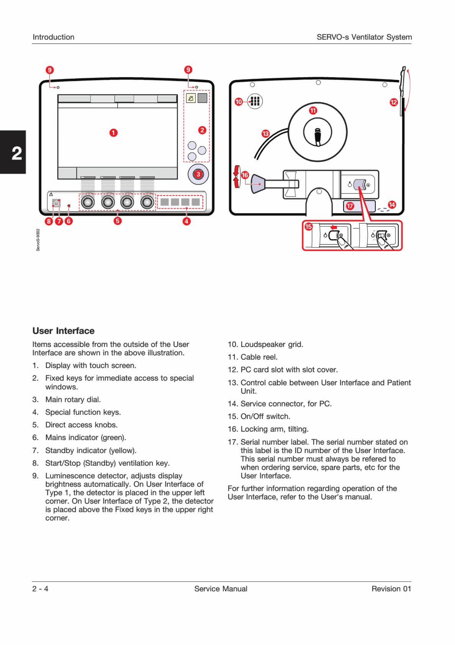
Items accessible from the outside of the User
Interface are shown in the above illustration.
1. Display with touch screen.
2. Fixed keys for immediate access to special
windows.
3. Main rotary dial.
4. Special function keys.
5. Direct access knobs.
6. Mains indicator (green).
7. Standby indicator (yellow).
8. Start/Stop (Standby) ventilation key.
9. Luminescence detector, adjusts display
brightness automatically. On User Interface ofType 1, the detector is placed in the upper leftcorner. On User Interface of Type 2, the detectoris placed above the Fixed keys in the upper rightcomer.
10. Loudspeaker grid.
11. Cable reel.
12. PC card slot with slot cover.
13. Control cable between User Interface and Patient
Unit.
14. Service connector, for PC.
15. On/Off switch.
16. Locking arm, tilting.
17. Serial number label. The serial number stated on
this label is the ID number of the User Interface.
This serial number must always be refered towhen ordering service, spare parts, etc for theUser Interface.
For further information regarding operation of theUser Interface, refer to the User's manual.
2 - 4 Service Manual Revision 01
SERVO-s Ventilator System Introduction
*
'IV
I
.1
i
1V
1
i4
i iI
i
1
t i '
v
>
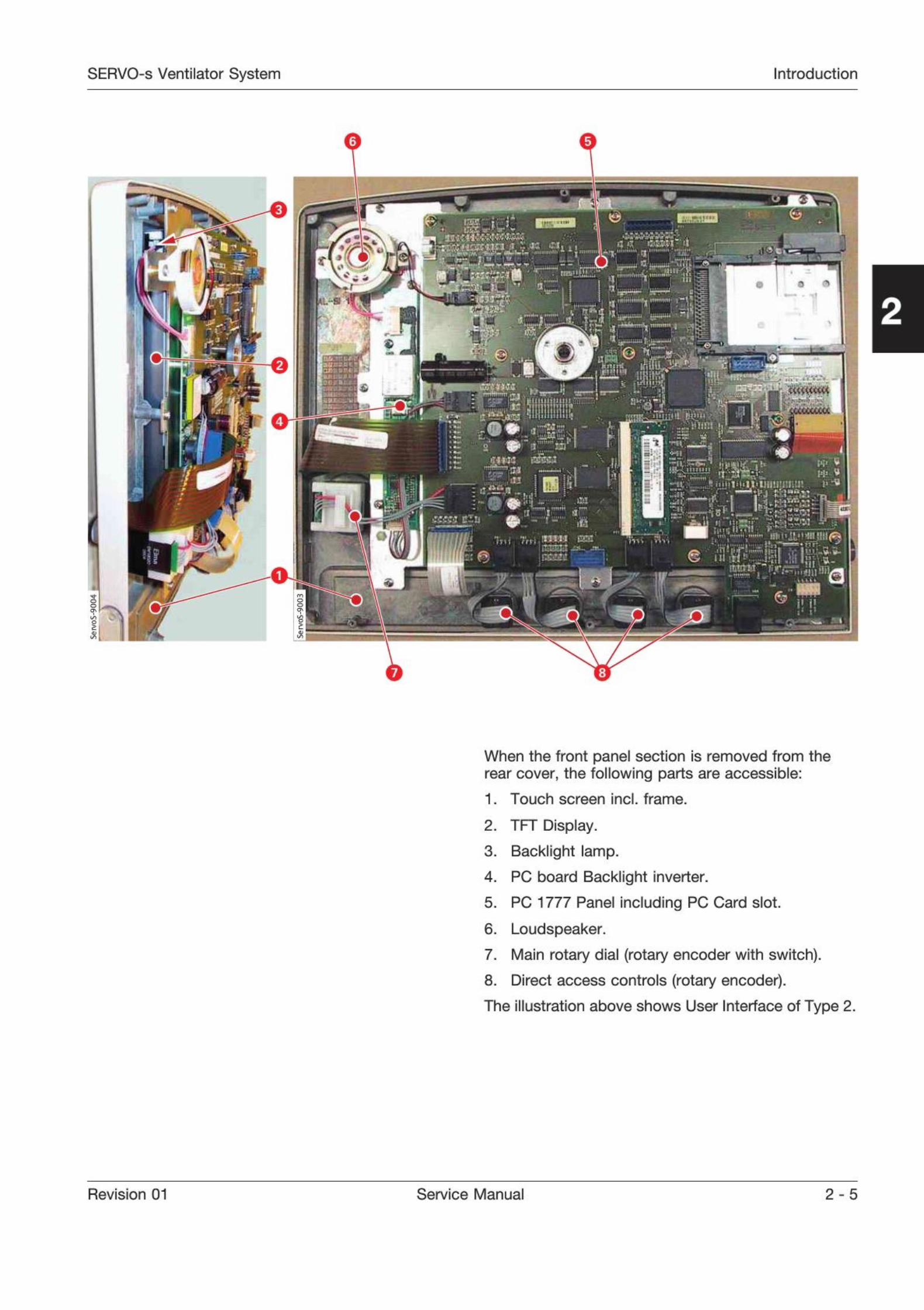
When the front panel section is removed from therear cover, the following parts are accessible:
1. Touch screen incl. frame.
2. TFT Display.
3. Backlight lamp.
4. PC board Backlight inverter.
5. PC 1777 Panel including PC Card slot.
6. Loudspeaker.
7. Main rotary dial (rotary encoder with switch).
8. Direct access controls (rotary encoder).
The illustration above shows User Interface of Type 2.
Revision 01 Service Manual 2 - 5
Introduction SERVO-s Ventilator System
®
111
1101
LD
s
o oO O <D O
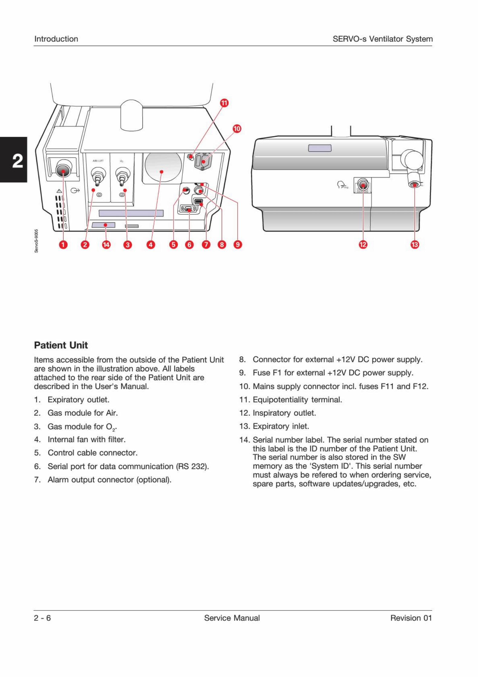
Patient Unit
Items accessible from the outside of the Patient Unit
are shown in the illustration above. All labels
attached to the rear side of the Patient Unit are
described in the User's Manual.
1. Expiratory outlet.
2. Gas module for Air.
3. Gas module for 0
2.
4. Internal fan with filter.
5. Control cable connector.
6. Serial port for data communication (RS 232).
7. Alarm output connector (optional).
8. Connector for external +12V DC power supply.
9. Fuse F1 for external +12V DC power supply.
10. Mains supply connector incl. fuses F11 and F12.
11. Equipotentiality terminal.
12. Inspiratory outlet.
13. Expiratory inlet.
14. Serial number label. The serial number stated on
this label is the ID number of the Patient Unit.The serial number is also stored in the SW
memory as the '
System ID'. This serial numbermust always be refered to when ordering service,spare parts, software updates/upgrades, etc.
2 - 6 Service Manual Revision 01
SERVO-s Ventilator System Introduction
.
P
1
1 9
r
\
nAHU
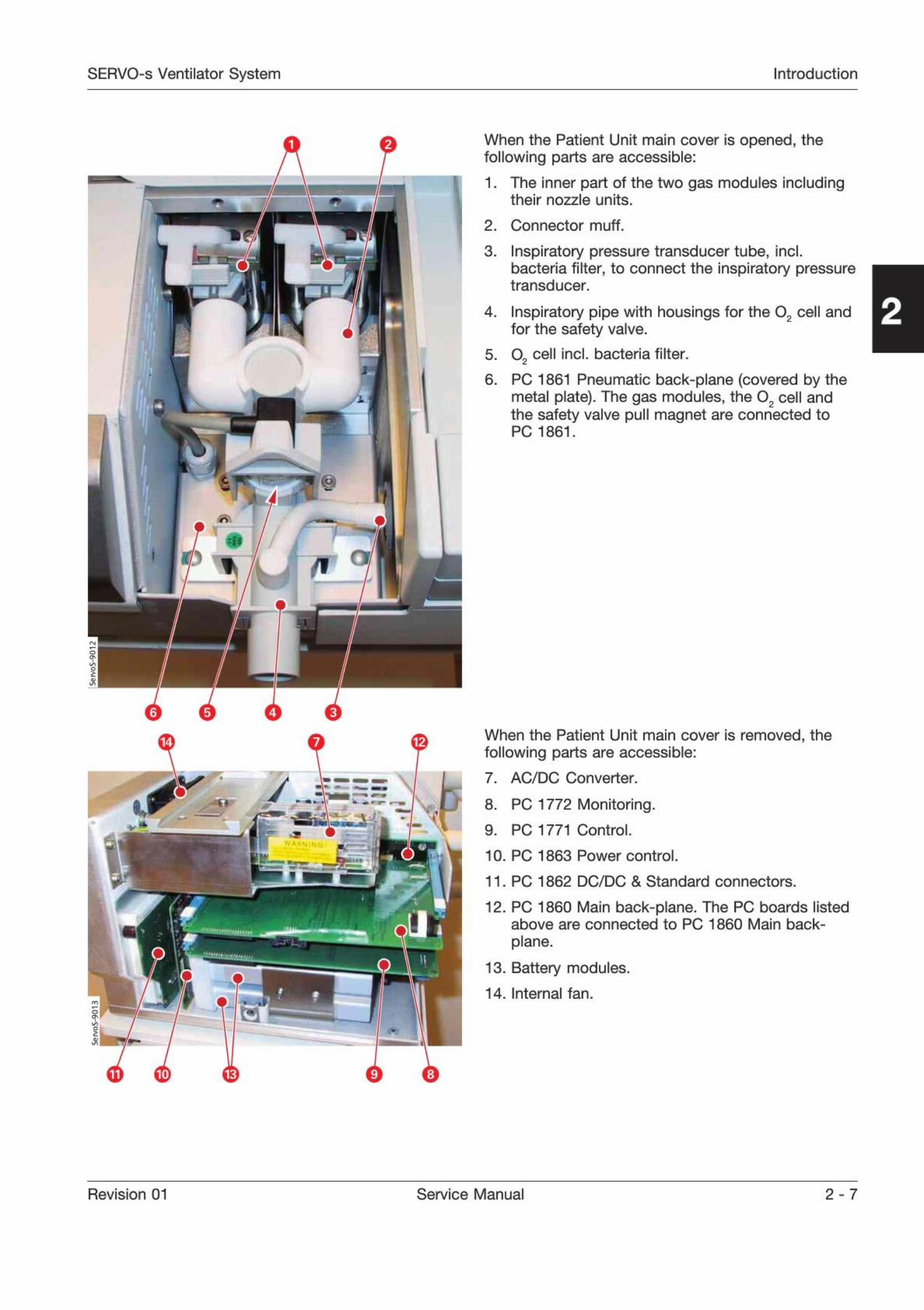
When the Patient Unit main cover is opened, thefollowing parts are accessible:
1. The inner part of the two gas modules including
their nozzle units.
2. Connector muff.
3. Inspiratory pressure transducer tube, incl.
bacteria filter, to connect the inspiratory pressuretransducer.
4. Inspiratory pipe with housings for the 02
cell and
for the safety valve.
5. 0
2 cell Incl. bacteria filter.
6. PC 1861 Pneumatic back-plane (covered by the
metal plate). The gas modules, the 02 cell and
the safety valve pull magnet are connected toPC 1861.
When the Patient Unit mam cover is removed, the
following parts are accessible:
7. AC/DC Converter.
8. PC 1772 Monitoring.
9. PC 1771 Control.
10. PC 1863 Power control.
11. PC 1862 DC/DC & Standard connectors.
12. PC 1860 Main back-plane. The PC boards listedabove are connected to PC 1860 Main back-
plane.
13. Battery modules.
14. Internal fan.
Revision 01 Service Manual 2 - 7

Introduction SERVO-s Ventilator System
I-
-
When the Patient Unit side cover is removed, the
following parts are accessible:
15. PC 1784 Expiratory channel with the twoconnected PC 1781 Inspiratory and ExpiratoryPressure Transducers.
16. PC 1785 Expiratory channel connector.
17. Expiratory valve coil.
>
The expiratory cassette (18) is a complete unit. Itcontains the following parts:
. Expiratory inlet with moisture trap.
. PC 1786 Expiratory channel cassette.
. Ultrasonic flowmeter.
. Heating foil to keep a stable temperature in theexpiratory gas.
. Pressure transducer connection, incl. bacteria
filter, to connect the expiratory pressuretransducer.
. Expiratory valve incl. valve membrane.
. Expiratory one-way valve.
The expiratory valve coil, mounted under theexpiratory cassette compartment, controls the valvemembrane in the cassette.
PC 1786 Expiratory channel cassette inside theexpiratory cassette is electrically connected toPC 1784 Expiratory channel via PC 1785 Expiratorychannel connector (16).
2 - 8 Service Manual Revision 01
SERVO-s Ventilator System Introduction
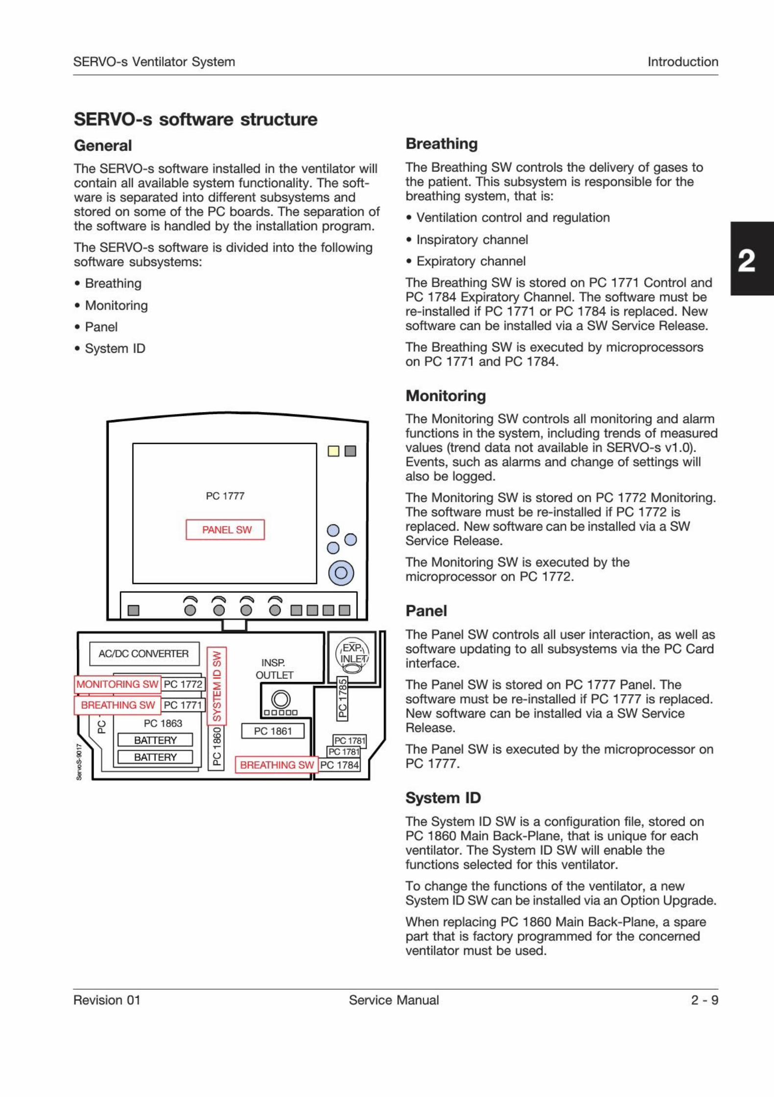
SERVO-s software structure
General
The SERVO-s software installed in the ventilator will
contain all available system functionality. The soft-ware Is separated into different subsystems andstored on some of the PC boards. The separation ofthe software is handled by the installation program.
The SERVO-s software is divided into the followingsoftware subsystems:
. Breathing
. Monitoring
. Panel
System ID
Breathing
The Breathing SW controls the delivery of gases tothe patient. This subsystem is responsible for thebreathing system, that is:
. Ventilation control and regulation
. Inspiratory channel
. Expiratory channel
The Breathing SW is stored on PC 1771 Control andPC 1784 Expiratory Channel. The software must bere-installed if PC 1771 or PC 1784 is replaced. Newsoftware can be installed via a SW Service Release.
The Breathing SW is executed by microprocessorson PC 1771 and PC 1784.
PC 1777
PANEL SW OO
o
@5
O O o o1
AC/DC CONVERTER
MONITORING SW PC 1772
BREATHING SW PC 1771:
PC 1863
BATTERY
BATTERY
CO
oCD
CC
o
INSR
OUTLET
o
PC 1861
EXP
NLET/
SI
Q.
BREATHING SW
PC178ljPC 1781
PC 1784
Monitoring
The Monitoring SW controls all monitoring and alarmfunctions in the system, including trends of measuredvalues (trend data not available in SERVO-s vl.O).Events, such as alarms and change of settings willalso be logged.
The Monitoring SW is stored on PC 1772 Monitoring.The software must be re-Installed if PC 1772 is
replaced. New software can be installed via a SWService Release.
The Monitoring SW is executed by themicroprocessor on PC 1772.
Panel
The Panel SW controls all user interaction, as well as
software updating to all subsystems via the PC Cardinterface.
The Panel SW is stored on PC 1777 Panel. The
software must be re-installed if PC 1777 is replaced.New software can be installed via a SW Service
Release.
The Panel SW is executed by the microprocessor onPC 1777.
System ID
The System ID SW is a configuration file, stored onPC 1860 Main Back-Plane, that is unique for eachventilator. The System ID SW will enable thefunctions selected for this ventilator.
To change the functions of the ventilator, a newSystem ID SW can be installed via an Option Upgrade.
When replacing PC 1860 Main Back-Plane, a sparepart that is factory programmed for the concernedventilator must be used.
Revision 01 Service Manual 2-9
Introduction SERVO-s Ventilator System
Notes
2 - 10 Service Manual Revision 01

SERVO-s Ventilator System Description of functions
Only personnel trained and authorizedby MAQUET shall be permitted toperform installation, service ormaintenance of the SERVO-s.
M.1
Make sure to prepare the SERVO-s properlybefore disassembling and assembling. Refer tosection 'Hazard notices' in chapter 'Important'.
Any service or maintenance must be noted in alog book.
After any installation, maintenance or serviceintervention in the SERVO-s, perform a 'Pre-usecheck'. Refer to the 'SERVO-s Ventilator SystemUser's Manual' for details.
This product contains electronic andelectrical components. Discarddisposable, replaced and left-over partsin accordance with appropriateindustrial and environmental standards.
3. Description of functions
About this chapter 3-2
Memory types used in the SERVO-s 3 - 2
User Interface 3-2
User Interface controls 3-2
PC 1777 Panel 3-2
Loudspeaker 3-2
Backlight Inverter 3 - 2
Touch screen including frame 3-2
TFT Display with Backlight 3 - 2
Patient unit 3-3
Inspiratory section 3-3
Expiratory section 3-6
PC 1860 Main back-plane 3 - 7
Pressure transducers 3-7
PC 1784 Expiratory Channel 3 - 8
PC 1771 Control 3-8
PC 1772 Monitoring 3-8
Power supply 3-9
Internal fan 3-10
Control cable 3-10
Revision 01 Service Manual 3-1
Description of functions SERVO-s Ventilator System
About this chapterThis text refers to the Functional Main Blocks
diagram in chapter 'Diagrams'.
Memory types used in the SERVO-sThere are four different types of memories used inthe SERVO-s:
. Flash memory. For System SW storage. Present onPC 1771. PC 1772, PC 1777 and PC 1784.
The System SW can be re-installed/updated usinga SW Service Release.
. RAM. For temporary storage of software and data.
Present on PC 1771, PC 1772 and PC 1777.
. Non-volatile memory. RAM with battery back-up.For settings, trends and logs. Present on PC 1771and PC 1772.
. EEPROM. For PC board information, configuration,
calibration data, etc. Present on almost all PC
boards and In the 02 cell.
User Interface
Functional Main Blocks diagram marking: 'U'.
There are two different versions of the User Interface.
In this manual, they are described as:
. Type 1 - Up to User Interface S/N 201200(SERVO-s S/N 02000).
. Type 2 - User Interface S/N 201201(SERVO-s S/N 02001) and higher.
There is no difference in the clinical operationbetween the two versions, but the electronics inside
the User Interface differs. As a consequence, someof the spare parts are not compatible between thetwo versions. Further Information can be found
below and also in the SERVO-s Spare Parts List.
User Interface controls
Setting of different parameter input values Is madewith the help of the following different interfacedevices:
. Main Rotary Dial (rotary encoder with switch).
. Direct Access Control, 4 each (rotary encoders).
. Membrane buttons. Integrated parts of the Touch
screen assembly.
. Touch screen.
PC 1777 Panel
Some features included on PC 1777 Panel are:
. SIMM (Single In-line Memory Module) mounted onits connector P77. Memory type: SDRAM
. PC Card Slot intended for connection/insert of a
PC Card. PC Cards are used to:
- Download software into the different flash
memories situated on PC-boards marked pP andinto the EEPROM on PC 1860 Main back-plane.
- Transfer patient and system data for furthertransfer to a computer.
- Service purpose.
. Microprocessor pP on this board includes controlof the functions of the User Interface.
. ID-PROM: The ID information can be read by theSERVO-s.
. On/Off switch: Switch to Power up or Power downthe SERVO-s System. Refer to section 'Powersupply
1
.
. Connection for PC (P86): Ethernet port intended fortest and service purpose. Connected via a servicecable. For future options.
. Microphone used to monitor sounds from theLoudspeaker.
There are two different versions of PC 1777, Type 1and Type 2. The PC 1777 spare parts is notcompatible between the two versions.
For PC 1777 of Type 2, System SW version V2.00.04or higher is required.
Note: The System SW must be re-installed If PC 1777is replaced.
Loudspeaker
For generation of sound, e.g. alarm. Connected toP72 on PC 1777 Panel.
The loudspeaker generates different tones withindividual sound volumes. At start-up and duringPre-use check the function of the loudspeaker ismonitored by the microphone on PC 1777. Duringoperation it is continuously monitored throughcurrent sensing.
By installing the accessory 'Loudspeaker booster kit1,the alarm sound is amplified in a mechanical way.The sound level will be Increased significantly. Thisincreased sound level will raise the complete alarmsound setting range (20%-100%), i.e. also the lowersound level range will be increased.
3-2 Service Manual Revision 01
SERVO-s Ventilator System Description of functions
Backlight Inverter
PC board with driving stage for backlight (lamps)mounted behind the TFT Display. The supply voltagedelivered by the Backlight Inverter is 660 V.
The Backlight Inverter is connected to P73 onPC 1777 Panel.
There are two different versions of the BacklightInverter, Type 1 and Type 2. The Backlight Inverterspare parts is not compatible between the twoversions.
Touch screen including frame
The Touch screen implies the touch function of thefront panel screen and is interactive with informationdisplayed on the Display. The front panel framewith the touch screen, membrane buttons and DIM
sensor forms the assembly Touch screen incl. frameand must be handled as one complete part. The DIMsensor measures the ambient light and the screenbrightness is automatically adjusted.
There are two different versions of the Touch screen
incl. frame. Type 1 and Type 2. The Touch screenincl. frame spare parts is not compatible between thetwo versions.
TFT Display with Backlight
The TFT Display is a Thin Film Transistor Screen forcolor display of picture- and alphanumeric data.
There are two different versions of the TFT Display:
. Type 1 with Backlight consisting of two separatefluorescent lamps mounted behind the TFT Screen.
. Type 2 with Backlight consists of one fluorescentlamp mounted behind the TFT Screen.
The TFT Display spare parts is not compatiblebetween the two versions.
The Backlight lamps are driven from the BacklightInverter. Estimated lifetime (with acceptablebrightness level) for the lamps is 30.000 hours.Using the Field Service System (FSS), a time meterfor the lamps can be shown. The time meter must bereset after replacement of the lamps.
Patient unit
Inspiratory section
Functional Main Blocks diagram marking: T.
The main block Inspiratory Section conveys thebreathing gas from its gas inlets for Air and 02 supplyto the patient breathing system. It comprises thefollowing main functions:
. Gas Modules - Air and 02.
. Connector Muff.
. Inspiratory Pipe.
. 02 Cell.
. Inspiratory Pressure Tube.
. Safety Valve including pull magnet.
. Inspiratory Outlet.
. PC 1861 Pneumatic Back-Plane.
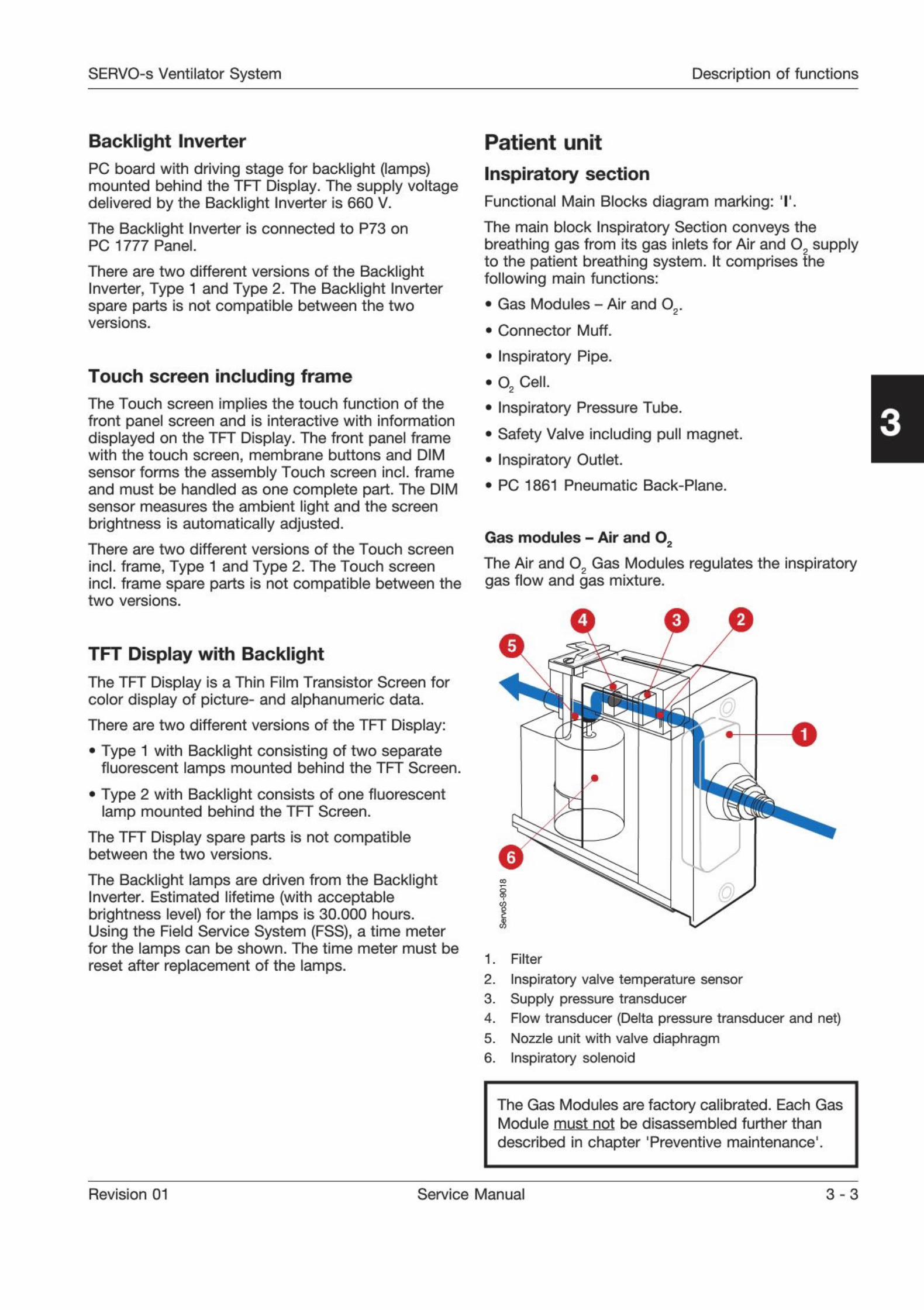
Gas modules - Air and O2
The Air and 02 Gas Modules regulates the inspiratory
gas flow and gas mixture.
4
1
O
1. Filter
2. Inspiratory valve temperature sensor
3. Supply pressure transducer
4. Flow transducer (Delta pressure transducer and net)
5. Nozzle unit with valve diaphragm
6. Inspiratory solenoid
The Gas Modules are factory calibrated. Each GasModule must not be disassembled further than
described in chapter 'Preventive maintenance1.
Revision 01 Service Manual 3-3
Description of functions SERVO-s Ventilator System
Gas inlet
Gas supply is connected to the ventilators gas inletnipples. The design of the gas inlet nipples varyaccording to the standard chosen.
Gas is to be connected from hospital central gassupply or from gas cylinders. The Air supply may beconnected from a compressor for medical air.
Filter
The Filter protects the ventilator from particles in thegas delivered to the Gas Modules. The filter must bereplaced during the
'Preventive maintenance'.
The filter housing and the filter cover are providedwith matching guide pins. These guide pins preventmounting of the filter cover (with gas inlet nipple) onthe wrong module.
A non-return valve for the gas inlet is located in thefilter cover. This valve will suppress short pressuredrops in the gas supply.
The non-return valve is also designed to slowlyevacuate compressed gas from the module, if thegas supply to the module is disconnected.
Inspiratory valve temperature sensor
The temperature of the supplied gas is measured bythe Inspiratory Valve Temperature Sensor. Thissensor is situated in the gas flow.
The output signal from this sensor is used tocompensate for the gas density variations due totemperature.
Nozzle unit
The plastic Nozzle Unit contains a valve diaphragm.The valve diaphragm, controlled by the InspiratorySolenoid, regulates the gas flow through the GasModule.
The complete plastic nozzle unit must be replacedduring the 'Preventive maintenance'.After replacement, allow the diaphragm to settleduring approx. 10 minutes before gas pressure isconnected to the Gas Module.
Inspiratory solenoid
The gas flow through the Gas Module is regulated bythe Inspiratory Solenoid via the Nozzle Unit.
The current supplied to the solenoid is regulated sothat the gas module will deliver a gas flow accordingto the settings on the User Interface.
Gas module key
The Gas Modules are provided with a mechanicalkey to prevent that the module is mounted in thewrong slot.
The key consists of a plastic guide mounted under-neath the module and a corresponding guidemounted in the patient unit.
ID PROM
Each Gas Module is provided with an ID-PROM. TheID information can be read by the SERVO-s.
Supply pressure transducer
The pressure of the supplied gas is measured by theSupply Pressure Transducer.
The output signal from this transducer is amplified. Itis then used to calculate the absolute pressure of thegas to compensate for gas density variations due topressure.
Flow transducer
The gas flows through a net (resistance) whichcauses a pressure drop. The pressure is measuredon both sides of this net and the differential pressurevalue is then amplified.
Connector muff
The Connector Muff connects the Gas Module
outlets to the inspiratory Pipe Inlet.
Inspiratory pipe
The Inspiratory Pipe leads the gas from theConnector Muff to the Inspiratory Outlet.
The Inspiratory Pipe comprises:
. Housing and locking lever for the 02 Cell with its
bacteria filter.
. Housing for the Safety Valve.
. Connection for measurement of inspiratorypressure.
The pipe is provided with internal flanges with thepurpose to improve mixing of 02 and Air.
3-4 Service Manual Revision 01
SERVO-s Ventilator System Description of functions
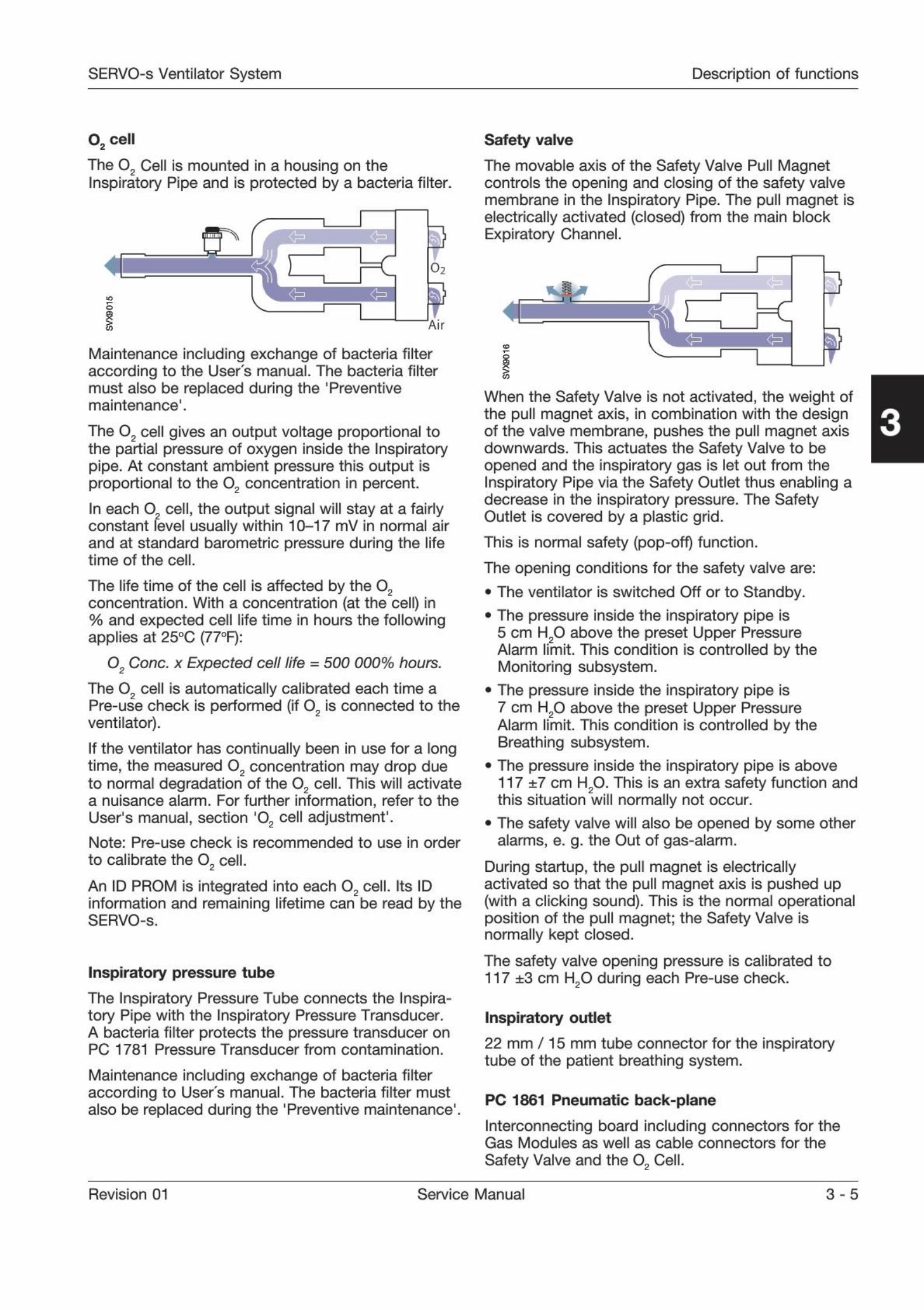
02 cell
The 02 Cell is mounted in a housing on the
Inspiratory Pipe and is protected by a bacteria filter.
i 02
1Air
Maintenance including exchange of bacteria filteraccording to the User
'
s manual. The bacteria filter
must also be replaced during the 'Preventive
maintenance1
.
The 02 cell gives an output voltage proportional to
the partial pressure of oxygen inside the Inspiratorypipe. At constant ambient pressure this output Isproportional to the 02 concentration in percent.In each 0
2 cell, the output signal will stay at a fairlyconstant level usually within 10-17 mV in normal airand at standard barometric pressure during the lifetime of the cell.
The life time of the cell is affected by the 02
concentration. With a concentration (at the cell) in% and expected cell life time in hours the followingapplies at 250C (770F):
02 Cone, x Expected cell life = 500 000% hours.
The 02 cell is automatically calibrated each time a
Pre-use check is performed (if 02 is connected to the
ventilator).
If the ventilator has continually been in use for a longtime, the measured 0
2 concentration may drop dueto normal degradation of the 02
cell. This will activate
a nuisance alarm. For further information, refer to the
User's manual, section ,02 cell adjustment'.
Note: Pre-use check Is recommended to use in order
to calibrate the 02 cell.
An ID PROM is integrated into each 02 cell. Its ID
information and remaining lifetime can be read by theSERVO-s.
Inspiratory pressure tube
The Inspiratory Pressure Tube connects the Inspira-tory Pipe with the Inspiratory Pressure Transducer.A bacteria filter protects the pressure transducer onPC 1781 Pressure Transducer from contamination.
Maintenance including exchange of bacteria filteraccording to User
'
s manual. The bacteria filter must
also be replaced during the 'Preventive maintenance1.
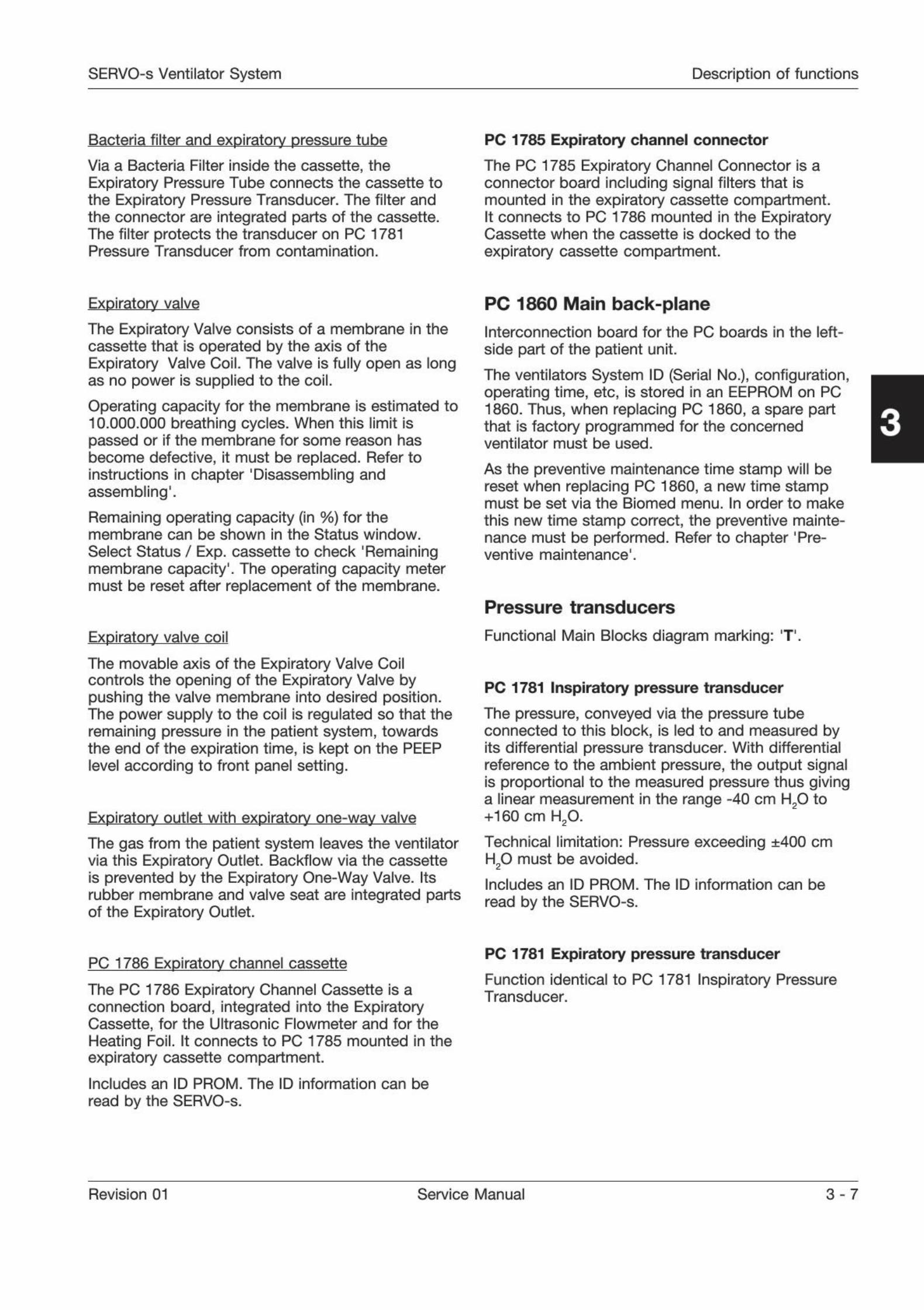
Safety valve
The movable axis of the Safety Valve Pull Magnetcontrols the opening and closing of the safety valvemembrane in the Inspiratory Pipe. The pull magnet iselectrically activated (closed) from the main blockExpiratory Channel.
1
f
When the Safety Valve is not activated, the weight ofthe pull magnet axis, in combination with the designof the valve membrane, pushes the pull magnet axisdownwards. This actuates the Safety Valve to beopened and the inspiratory gas is let out from theInspiratory Pipe via the Safety Outlet thus enabling adecrease in the inspiratory pressure. The SafetyOutlet is covered by a plastic grid.
This is normal safety (pop-off) function.
The opening conditions for the safety valve are:
The ventilator is switched Off or to Standby.
. The pressure inside the inspiratory pipe is5 cm H
20 above the preset Upper PressureAlarm limit. This condition is controlled by theMonitoring subsystem.
. The pressure inside the inspiratory pipe is7 cm H
20 above the preset Upper PressureAlarm limit. This condition is controlled by theBreathing subsystem.
. The pressure inside the inspiratory pipe is above117 ±7 cm H
20
. This is an extra safety function andthis situation will normally not occur.
. The safety valve will also be opened by some otheralarms, e. g. the Out of gas-alarm.
During startup, the pull magnet is electricallyactivated so that the pull magnet axis is pushed up(with a clicking sound). This is the normal operationalposition of the pull magnet; the Safety Valve isnormally kept closed.
The safety valve opening pressure is calibrated to117 ±3 cm H
20 during each Pre-use check.
Inspiratory outlet
22 mm / 15 mm tube connector for the inspiratorytube of the patient breathing system.
PC 1861 Pneumatic back-plane
Interconnecting board including connectors for theGas Modules as well as cable connectors for the
Safety Valve and the 02 Cell.
3
Revision 01 Service Manual 3 - 5

Description of functions SERVO-s Ventilator System
Expiratory section
Functional Main Blocks diagram marking: 'E1.
The main block Expiratory Section conveys thebreathing gas from the patient breathing system tothe Expiratory Outlet. It comprises:
. Measurement of expiratory flow
. Connection for measurement of expiratorypressure.
. Controlling element for the regulation of expiratorypressure.
Expiratory cassette
The expiratory gas conveying parts and PC 1786Expiratory Channel Cassette are integrated into onepart - the Expiratory Cassette - which can be easilyremoved for cleaning or exchange. See SERVO-sVentilator System - User's manual.
The expiratory cassette can be interchangedbetween different SERVO-s systems. A Pre-usecheck is always required after exchanging theexpiratory cassette.
A re-designed version of the Expiratory cassette wasintroduced during 01 2005 starting with cassette S/N35000. The new cassette has a larger pressuretransducer channel and this will significantly reducethe drying time needed before use.
Ultrasonic
transducer
PC 1786
Expiratorychannel cassette
Ultrasonic
transducer
\r 1
7-
Heatingfoil
Bacteria Expiratory pressurefilter tube connector
Expiratory inlet
22 mm / 10 mm tube connector for the expiratorytube of the patient breathing system. The inlet isdesigned to make condensed water drip out andallow use of a water trap for such water to becollected. Expiratory inlet bacteria filter can beconnected to protect the cassette fromcontamination.
Heating foil
An electrical Heating Foil applied on the outside ofthe expiratory pipe where the Ultrasonic Flowmeteris situated. The purpose of the Heating Foil to reducecondensation and maintain a stable temperature inthe expiratory gas.
Ultrasonic flowmeter
The Ultrasonic Flowmeter is a measuring device forthe expiratory gas flow, using ultrasound techniquewith two ultrasonic transducers/receivers.
The measuring process is controlled from the mainblock PC 1784 Expiratory Channel.
Q
The left hand side transducer is sending outultrasonic sound that is reflected against the innerwall of the expiratory channel. The ultrasonic soundis received by the right hand side transducer nowacting as a receiver. The time from sending toreceiving ultrasonic sound in downstream expiratorygas flow Is measured.
Then the right hand side transducer (earlier receiving)is sending out ultrasonic sound upstream theexpiratory gas flow. The ultrasonic sound is receivedby the left hand side transducer now acting as areceiver. The time from sending to receivingultrasonic sound in upstream expiratory gas flow ismeasured.
The time difference between the downstream and
the upstream time measurements provides flowinformation.
A temperature sensor Inside the cassette measuresthe expiratory gas temperature. This temperaturemeasurement Is also used when calculating theexpiratory flow.
3 - 6 Service Manual Revision 01
SERVO-s Ventilator System Description of functions
Bacteria filter and expiratory pressure tube
Via a Bacteria Filter inside the cassette, the
Expiratory Pressure Tube connects the cassette tothe Expiratory Pressure Transducer. The filter andthe connector are integrated parts of the cassette.The filter protects the transducer on PC 1781Pressure Transducer from contamination.
PC 1785 Expiratory channel connector
The PC 1785 Expiratory Channel Connector is aconnector board including signal filters that ismounted in the expiratory cassette compartment.It connects to PC 1786 mounted in the ExpiratoryCassette when the cassette is docked to the
expiratory cassette compartment.
Expiratory valve
The Expiratory Valve consists of a membrane in thecassette that is operated by the axis of theExpiratory Valve Coil. The valve is fully open as longas no power Is supplied to the coil.
Operating capacity for the membrane is estimated to10.000.000 breathing cycles. When this limit ispassed or if the membrane for some reason hasbecome defective, it must be replaced. Refer toinstructions in chapter 'Disassembling andassembling'
.
Remaining operating capacity (in %) for themembrane can be shown in the Status window.
Select Status / Exp. cassette to check 'Remainingmembrane capacity'
. The operating capacity metermust be reset after replacement of the membrane.
Expiratory valve coil
The movable axis of the Expiratory Valve Coilcontrols the opening of the Expiratory Valve bypushing the valve membrane into desired position.The power supply to the coil is regulated so that theremaining pressure in the patient system, towardsthe end of the expiration time, is kept on the PEEPlevel according to front panel setting.
Expiratory outlet with expiratory one-way valve
The gas from the patient system leaves the ventilatorvia this Expiratory Outlet. Backflow via the cassetteis prevented by the Expiratory One-Way Valve. Itsrubber membrane and valve seat are integrated partsof the Expiratory Outlet.
PC 1860 Main back-plane
Interconnection board for the PC boards in the left-
side part of the patient unit.
The ventilators System ID (Serial No.), configuration,operating time, etc, is stored in an EEPROM on PC1860. Thus, when replacing PC 1860, a spare partthat is factory programmed for the concernedventilator must be used.
As the preventive maintenance time stamp will bereset when replacing PC 1860, a new time stampmust be set via the Biomed menu. In order to make
this new time stamp correct, the preventive mainte-nance must be performed. Refer to chapter
'Pre-
ventive maintenance'
.
Pressure transducers
Functional Main Blocks diagram marking: T.
PC 1781 Inspiratory pressure transducer
The pressure, conveyed via the pressure tubeconnected to this block, is led to and measured byits differential pressure transducer. With differentialreference to the ambient pressure, the output signalis proportional to the measured pressure thus givinga linear measurement in the range -40 cm H2
0 to
+160 cm H20
.
Technical limitation: Pressure exceeding ±400 cmH
20 must be avoided.
Includes an ID PROM. The ID information can be
read by the SERVO-s.
PC 1786 Expiratory channel cassette
The PC 1786 Expiratory Channel Cassette is aconnection board, integrated into the ExpiratoryCassette, for the Ultrasonic Flowmeter and for the
Heating Foil. It connects to PC 1785 mounted in theexpiratory cassette compartment.
Includes an ID PROM. The ID information can be
read by the SERVO-s.
PC 1781 Expiratory pressure transducer
Function identical to PC 1781 Inspiratory PressureTransducer.
Revision 01 Service Manual 3 - 7
Description of functions SERVO-s Ventilator System
PC 1784 Expiratory channel
Functional Main Blocks diagram marking: 'F'.
The main block Expiratory channel comprisesmicroprocessor control to achieve measurement ofexpiratory flow. The output signal Exp. Flow is usedin the main block Control.
Electronics including microprocessor (pP) forhandling of:
. All electronic connections to and from the
Expiratory Section functions.
. Measurement of airway pressures in bothInspiratory Section and Expiratory Section.
. Control of the Safety Valve functions in theInspiratory Section.
A thermistor on PC 1784 monitors the temperatureinside the Patient Unit. An alarm Is activated if the
temperature is 77 ±5 0C (170 ±9 0F) or higher.
Includes an ID PROM. The ID information can be
read by the SERVO-s.
Note: The System SW must be re-installed If PC1784 is replaced.
PC 1771 Control
Functional Main Blocks diagram marking: 'C.
The main block Control comprises microprocessorcontrol of Breathing pattern for all differentventilation modes.
Electronics including microprocessor (pP) control toachieve:
1. Regulation of Inspiratory flow which Is used during
inspiration time in Volume Control (VC) mode.
2. Regulation of Inspiratory pressure which can be
used during inspiration time in any mode.
3. Regulation of a constant Inspiratory flow which is
used during expiration time in all modes.
4. Respiratory timing pattern including frequency as
well as distribution of the duration for Inspirationtime, Pause time and Expiration time accordingto front panel settings.
5. Regulation of Inspiratory flow during inspiration
time. The desired total Inspiratory flow valueaccording to front panel settings is used togenerate the flow reference signals Insp Flow Ref1 and Insp Flow Ref 2. The level relation betweenthese two flow reference signals depends on thedesired 0
2 concentration according to front panelsetting. Insp Flow Ref 1 and Insp Flow Ref 2 areused for the control of its respective Gas Module(Air and O ).
Regulation of a constant Inspiratory flow duringexpiration time: The desired constant Inspiratory flowvalue is the default Bias flow value (see User'smanual).
This desired constant Inspiratory flow value is usedto generate the flow reference signals Insp Flow Ref1 and Insp Flow Ref 2 with the same relation andsame handling as described above under 'Regulationof Inspiratory flow
'
except this occurs duringexpiration time.
Includes an ID PROM. The ID Information can be
read by the SERVO-s.
Note: The System SW must be re-installed ifPC 1771 is replaced.
A lithium battery on PC 1771 power supplies theinternal memory on the PC board. If the battery onPC 1771 is disconnected or if the battery voltage Istoo low, user default configurations made via theField Service System (FSS) and Pre-use checkresults including transducer calibrations will beerased. The lithium batteries must be replaced after5 years.
PC 1772 Monitoring
Functional Main Blocks diagram marking: 'M1.
The main block Monitoring comprises microprocessor{[}?) calculation of parameters and monitoring ofalarm limits with control of alarms (as well as back-up alarm). The main block Monitoring co-operateswith the Loudspeaker In the User Interface.
The PC 1772 Monitoring handles all supervision andalarms In the system. It activates pressure reducingmechanisms, including activation of the safety valve,in case of excessive breathing system pressure.
All alarms are conveyed and displayed on the frontpanel and the alarm sound is also generated. In caseof malfunction in the loudspeaker located on PC1777 Panel, a back-up sound generating device(buzzer) on PC 1772 will be activated automatically.This buzzer is monitored by a microphone at startupand during the Pre-use check.
The following voltages are supervised:. +24 V
. +12 V
. -12 V
. +5 V
. +3.3 V.
The buzzer on PC 1772 Monitoring generates thealarm signal In case of +5 V or +3.3 V power failure.The buzzer and +5 V / +3.3 V failure logic is poweredby back-up capacitors in case of power failure.
3 - 8 Service Manual Revision 01
SERVO-s Ventilator System Description of functions
The alarm signal used by the optional 'Alarm outputconnection1
is generated on PC 1772.
PC 1772 also contains a barometric transducer and
the measured barometric pressure is supplied to theother sub-units in the system.
Trending of measured parameters are performed byMonitoring.
A thermistor on PC 1772 monitors the temperatureinside the Patient Unit. An alarm is activated if the
temperature is 77 ±5 0C (170 ±9 0F) or higher.
Includes an ID PROM. The ID information can be
read by the SERVO-s.
Note: The System SW must be re-installed if PC 1772is replaced.
A lithium battery on PC 1772 power supplies theinternal memory on the PC board. If the battery onPC 1772 is disconnected or if the battery voltage istoo low, all logs and Pre-use check results includingtransducer calibrations will be erased. The lithium
batteries must be replaced after 5 years.
Power supply
Functional Main Blocks diagram marking: 'P'.
The main block Power Supply comprises conversionof mains power to internal power supply as well asconnections for the Battery modules.
The power modes in the SERVO-s System are:
. At Power up. i. e. when the On/Off switch is turned
On, all internal voltages will be enabled.
. At Power down, the Power supply system will
deactivate the hardware signal Power_
Good.H,and at the same time keep the internal voltages+5 V and +3.3 V for at least 1 ms, in order to let the
different subsystems save their current settings innon-volatile memory. Power down can be causedby:- Turning the On/Off switch Off.- Mains failure resulting in a switch to battery, but
the back-up battery voltage is too low for properoperation of the system.
- The system is powered from a battery, but thebattery voltage becomes too low for properoperation of the system.
In this Off mode, only charging of Battery modulesis enabled (if the system is connected to mains).All other circuitry is un-powered.
. In Standby all circuitry is powered from the Powersupply, but no breathing will be active. Theoperator can set all parameters, includingbreathing mode, during Standby.
If the internal DC supply voltage +12 V_
Unreg dropsbelow 10 V, due to power supply failure, the powersupply source will automatically switch. Thefollowing power supply source priority is used:
1. Mains power
2. External +12 V DC supply (if connected)
3. Backup Battery modules.
Power supply selection is managed by:
. PC 1862 - Between Mains power and External+12 V DC supply.
. PC 1863 - Between Mains power/External+12 V DC and Battery module power supply.
Mains inlet
Inlet for mains power supply including groundingconnection.
The SERVO-s System will automatically adjust to theconnected mains power if the mains power is withinspecified range. No voltage or frequence setting isrequired.
The mains inlet is equipped with two mains powerfuses, F11 and F12, rated 2.5 A.
AC/DC Converter
Converts the connected AC Power to the internal DC
supply voltage +12 VJJnreg.
PC 1862 DC/DC & Standard connectors
Converts the internal DC supply voltage +12 V_
Unreginto the following internal DC supply voltages:. +24 V
. +12 V
. -12 V
. +5 V
. +3.3 V
All standard connectors are located on this board.
The connectors are the following:
. N26 - External +12 V DC supply input. The
connector is equipped with a fuse F1, rated 10 A.There are no alarms indicating power supply failurerelated to the External +12 V DC supply. Thus,when the External +12 V DC supply is used,backup Battery modules must be installed toensure proper operation.
. N28 - Control cable.
. N29 - RS232.
Revision 01 Service Manual 3-9
Description of functions SERVO-s Ventilator System
. P63 - Alarm output connector. The connector is
mounted on all units but the optional 'Alarm
output'-function must be enabled in the
configuration software. The Alarm outputconnector enables connection of an external alarm
signal system to the SERVO-s. High and mediumpriority alarms are transferred, and the alarmoutput signal is active as long as the audio alarm isactive on the ventilator.
For further information, refer to the 'Alarm outputconnector - Reference Manual'
Pin configuration and signal names can be found inchapter 'Diagrams'.
Includes an ID PROM. The ID Information can be
read by the SERVO-s.
PC 1863 Power control
Connects and controls charging of the Batterymodules.
A Temperature Sensor is integrated on PC 1863. Thissensor measures the temperature inside the PatientUnit. The output signal, corresponding to thetemperature inside the Patient Unit, is used forregulation of the Internal Fan.
Includes an ID PROM. The ID information can be
read by the SERVO-s.
Battery modules
There are two backup Battery modules connected.The Battery module is a 12 V / 3.5 Ah Nickel-MetalHydride rechargeable 'smart battery'.
To calculate Its own status, the battery uses aninternal highly accurate voltmeter, amperemeter andtime clock to measure actual charge in and out of thebattery. In addition, there are algorithms tocompensate for the effects of discharge rate,discharge temperature, self-discharge and chargingefficiency, etc.
Even with this technology, the only time at which thebattery charge status is absolutely reliable is when itis either completely full or completely empty. What'smore, if the battery only sees partial charges anddischarges during its application, then it may not getthe benefit of a 'full' or 'empty' reference point forsome time, and must rely more and more on itscalculated figure.
The life span for the Battery module is calculated totwo and a half year from manufacturing date. Normaltime for logistics and storage are included in thiscalculation. The calculation corresponds thus to anestimated operational time of two years.Manufacturing date (year-week) is printed on thebattery label.
System SW version V2.01.00 (or higher) includes animproved monitoring of the battery status. ThisSystem SW will, among others, monitor:
. Expiry date.
. If the operational capacity is too poor for continuedusage.
In both cases, battery replacement information willbe shown on the User Interface.
Select 'Status / Batteries' on the User Interface to
check battery status. For further information, refer tochapter
'
Service procedures', section 'Batterymodules'
.
With the charge status indicator on the UserInterface, the four green LEDs on the Battery moduleare no longer required and will be removed from theBattery modules.
Recharge time for a discharged battery is approx.3 hours/battery. If a battery is fully discharged, e.g.due to long storage time, it may require up to 12hours charging time.
Each Battery module includes an ID PROM. The IDinformation can be read by the SERVO-s.
Internal fan
The Interna! Fan forces cooling air through thePatient Unit. The cooling air flow inside the PatientUnit is indicated in the 'Functional Main Block
Diagram'.
The Internal Fan is controlled by the TemperatureSensor on PC 1863 Power control. The fan will start
with half effect at approx. 33 0C (91 0F) and with fulleffect at approx. 43 0C (109 0F).
When the
temperature drops below approx. 37 0C (99 0F), thefan turns to half effect and when the temperaturedrops below approx. 27 0C (81 0F), the fan stops.
The air inlet is protected by a filter that must becleaned or replaced during the
'Preventive
maintenance'.
Control cable
This Control cable connects the Patient Unit and the
User Interface. The cable can be partly winded upunder a rubber cover on the rear of the User
Interface.
Note: The Control cable must only be connected ordisconnected when the ventilator is switched Off.
3 - 10 Service Manual Revision 01
SERVO-s Ventilator System Disassembling and assembling
Only personnel trained and authorizedby MAQUET shall be permitted toperform installation, service ormaintenance of the SERVO-s.
Make sure to prepare the SERVO-s properlybefore disassembling and assembling. Refer tosection 'Hazard notices' in chapter 'Important1.
Any service or maintenance must be noted in alog book.
After any installation, maintenance or serviceintervention in the SERVO-s, perform a 'Pre-usecheck'
. Refer to the 'SERVO-s Ventilator System -User's Manual' for details.
This product contains electronic andelectrical components. Discarddisposable, replaced and left-over partsin accordance with appropriateindustrial and environmental standards.
4. Disassembling andassembling
General 4-2
Preparations 4-2
Handling PC boards 4 - 2
Replacing PC boards 4-2
Assembling guidelines 4-2
Tightening torque 4-2
Threadlocking adhesives 4-2
User Interface 4-3
PC 1777 Panel 4 - 4
Backlight inverter 4 - 6
TFT Display 4 - 7
Backlight lamps 4 - 9
Touch screen including frame 4-10
Patient Unit 4-12
Main and side covers 4-12
Remove the User Interface from
the Patient Unit 4 - 13
Gas modules 4-13
Battery modules 4-14
PC 1771 Control and PC 1772 Monitoring.... 4-14
AC/DC Converter 4-14
PC 1863 Power control 4-15
PC 1862 DC/DC & Standard connectors 4-15
PC 1860 Main back-plane
Internal fan
4-15
4-16
Inspiratory channel 4-16
Safety valve membrane 4-16
PC 1861 Pneumatic back-plane 4-17
PC 1784 Expiratory channel 4-17
PC 1785 Expiratory channel connector 4-18
Expiratory valve coil 4-18
Expiratory cassette membrane 4-19
Control cable 4 - 20
4-1Revision 01 Service Manual

Disassembling and assembling SERVO-s Ventilator System
4
General
Disassembling of the SERVO-s is described in thischapter. If not stated otherwise, the assemblingprocedure is the reverse of the describeddisassembling procedure.
The illustrations in the SERVO-s Spare Parts List arevery useful as a guide when disassembling andassembling the SERVO-s.
PreparationsBefore disassembling or assembling the SERVO-s:
. Set the On / Off switch on the User Interface to
Off.
. Disconnect the mains power cable.
. Disconnect the gas supplies (wall and/orcylinder).
. Make sure that all gas conveying parts arecleaned according to instructions in the'
SERVO-s Ventilator System - User's manual'.
After any service intervention in the SERVO-s,perform a
'
Pre-use check' according toinstructions in the 'SERVO-s Ventilator System -User's manual1.
Handling PC boardsThe PC boards contain componentsthat are highly sensitive to staticelectricity.
Those who come into contact with
circuit boards containing sensitivecomponents must take certainprecautions to avoid damaging thecomponents (ESD protection).
When working with ESD sensitive components,always use a grounded wrist band and groundedwork surface. Adequate service tools must also beused.
PC boards (spare parts) must always be kept inprotective packaging for sensitive electronic device.
PC boards must not be inserted or removed while
the mains power or battery power is applied to thePC boards.
Remove and insert the PC boards very carefully toavoid damage to the connectors.
Replacing PC boardsThe SERVO-s System SW is distributed on differentsubsystems, located on the following PC boards:
. PC 1771 Control
. PC 1772 Monitoring
. PC 1784 Expiratory Channel
. PC 1777 Panel.
When delivered as spare parts, these PC boards areequipped with a
'
System SW version1 that may differfrom the version on the unit to be repaired.To keep the 'System SW version' used prior to thePC board replacement, the applicable 'System SWversion' must be available on a PC Card for re-
installation purposes.
For functionality enhancement, the latest released'
System SW version' is always recommended.
Before installing a new 'System SW version' on a unit,ensure that the software is fully compatible with allHW-, SW- and mechanical components in the unit.If any compatibility conflicts are apparent this will benoted on the 'MAQUET Critical Care SW download'web site.
Assembling guidelinesAll parts of the unit assembled with screws and nutsare tightened with a specified torque. In the UserInterface, some of the screws are also secured with
threadlocking adhesives as noticed duringdisassembling.
In order to maintain these specifications over time, itmust be ensured that after any service interventionremoved parts are re-assembled and securedaccording to instructions. Make sure to follow theguidelines stated below.
Tightening torque
. Thread size M3: 0.95 ±0.05 Nm
. Thread size M4-M6: 3.1 ±0.1 Nm.
Threadlocking adhesives. Electrolube Bloc'Lube BLV15ML® on threads in
contact with PC boards.
. Loctite 243® on all other threads.
4-2 Service Manual Revision 01
SERVO-s Ventilator System Disassembling and assembling
11
9
V
500
.c.
o
User Interface
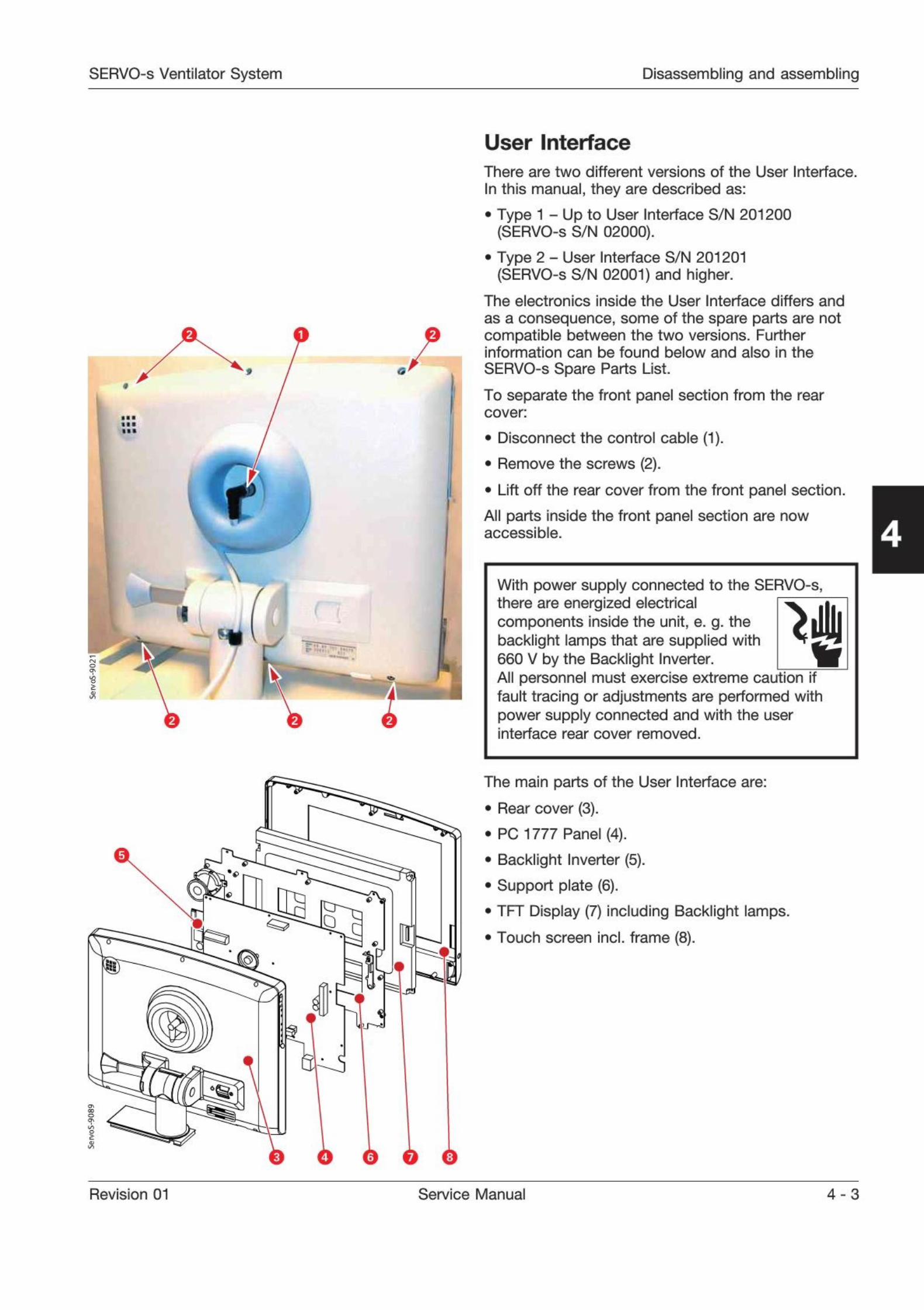
There are two different versions of the User Interface.
In this manual, they are described as:
. Type 1 - Up to User Interface S/N 201200(SERVO-s S/N 02000).
. Type 2 - User Interface S/N 201201(SERVO-s S/N 02001) and higher.
The electronics inside the User Interface differs and
as a consequence, some of the spare parts are notcompatible between the two versions. Furtherinformation can be found below and also in the
SERVO-s Spare Parts List.
To separate the front panel section from the rearcover:
. Disconnect the control cable (1).
. Remove the screws (2).
. Lift off the rear cover from the front panel section.
All parts inside the front panel section are nowaccessible. 4
With power supply connected to the SERVO-s,there are energized electricalcomponents inside the unit, e. g. thebacklight lamps that are supplied with660 V by the Backlight Inverter.All personnel must exercise extreme caution iffault tracing or adjustments are performed withpower supply connected and with the userinterface rear cover removed.
The main parts of the User Interface are:
. Rear cover (3).
. PC 1777 Panel (4).
. Backlight Inverter (5).
. Support plate (6).
. TFT Display (7) including Backlight lamps.
. Touch screen incl. frame (8).
Revision 01 Service Manual 4 - 3
Disassembling and assembling SERVO-s Ventilator System
4
MM*
0 a
r 1
tawu
.8
Typel =PC1777A-D
i
1
1t
P
*
r i
v
i
o
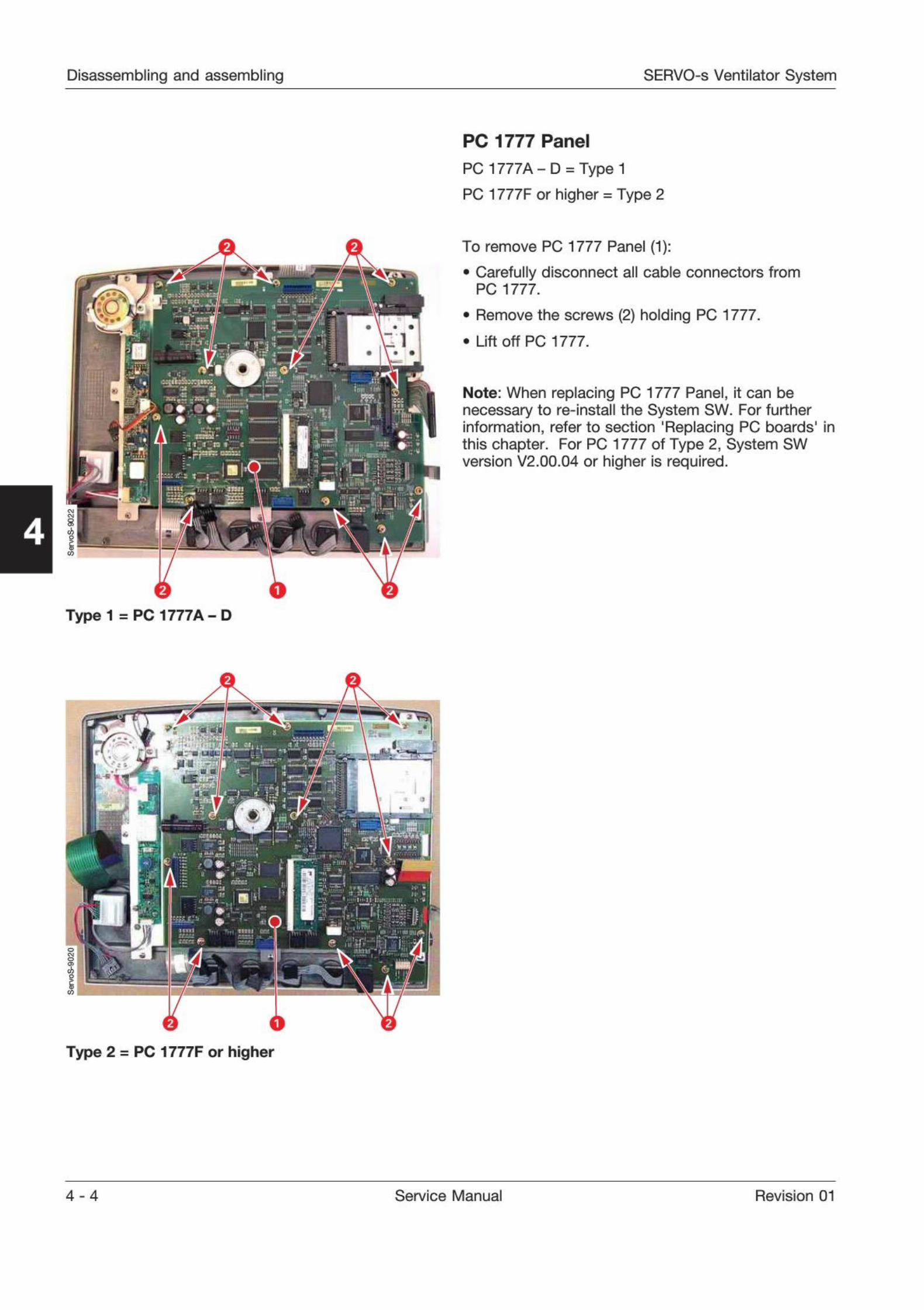
PC 1777 Panel
PC 1777A-D = Typel
PC 1777F or higher = Type 2
To remove PC 1777 Panel (1):
. Carefully disconnect all cable connectors fromPC 1777.
. Remove the screws (2) holding PC 1777.
. Lift off PC 1777.
Note: When replacing PC 1777 Panel, it can benecessary to re-install the System SW. For furtherinformation, refer to section 'Replacing PC boards' inthis chapter. For PC 1777 of Type 2, System SWversion V2.00.04 or higher is required.
Type 2 = PC 1777F or higher
4-4 Service Manual Revision 01
SERVO-s Ventilator System Disassembling and assembling
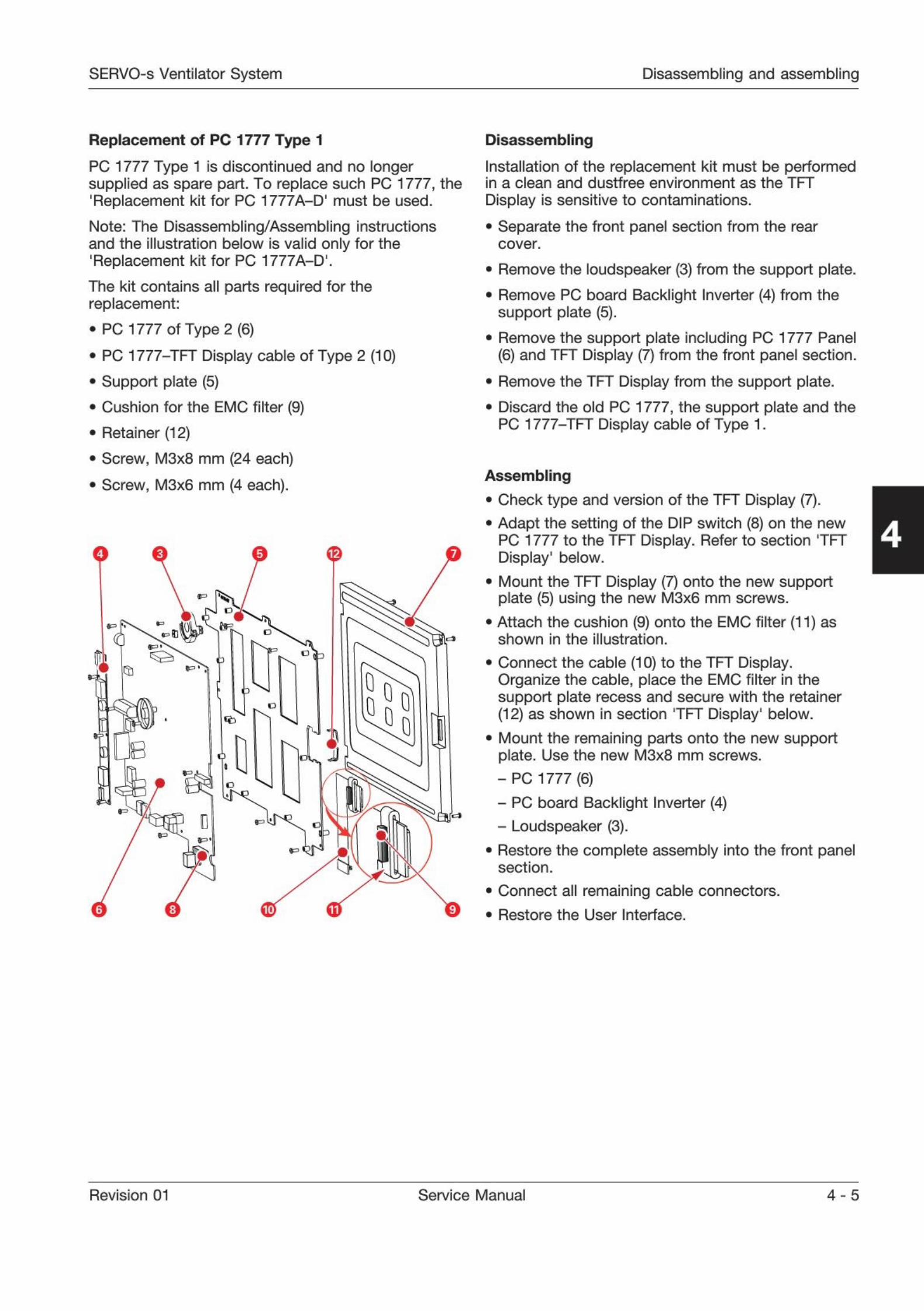
Replacement of PC 1777 Type 1
PC 1777 Type 1 is discontinued and no longersupplied as spare part. To replace such PC 1777, the'
Replacement kit for PC 1777A-D1 must be used.
Note: The Disassembling/Assembling instructionsand the illustration below is valid only for the'Replacement kit for PC 1777A-D,.
The kit contains all parts required for thereplacement:
. PC 1777 of Type 2 (6)
. PC 1777-TFT Display cable of Type 2 (10)
. Support plate (5)
. Cushion for the EMC filter (9)
. Retainer (12)
. Screw, M3x8 mm (24 each)
. Screw, M3x6 mm (4 each).
r 1
Hp: i
,"1
3
1
00
0s
1 J
Lr-
Disassembling
Installation of the replacement kit must be performedin a clean and dustfree environment as the TFT
Display is sensitive to contaminations.
. Separate the front panel section from the rearcover.
. Remove the loudspeaker (3) from the support plate.
. Remove PC board Backlight Inverter (4) from thesupport plate (5).
. Remove the support plate including PC 1777 Panel(6) and TFT Display (7) from the front panel section.
. Remove the TFT Display from the support plate.
. Discard the old PC 1777, the support plate and the
PC 1777-TFT Display cable of Type 1.
Assembling
. Check type and version of the TFT Display (7).
. Adapt the setting of the DIP switch (8) on the newPC 1777 to the TFT Display. Refer to section TFTDisplay' below.
. Mount the TFT Display (7) onto the new supportplate (5) using the new M3x6 mm screws.
. Attach the cushion (9) onto the EMC filter (11) asshown in the illustration.
. Connect the cable (10) to the TFT Display.
Organize the cable, place the EMC filter in thesupport plate recess and secure with the retainer(12) as shown in section TFT Display' below.
. Mount the remaining parts onto the new supportplate. Use the new M3x8 mm screws.- PC 1777 (6)- PC board Backlight Inverter (4)- Loudspeaker (3).
. Restore the complete assembly into the front panelsection.
. Connect all remaining cable connectors.
. Restore the User Interface.
4
Revision 01 Service Manual 4 - 5
Disassembling and assembling SERVO-s Ventilator System
If-.
....
11
HUM
I
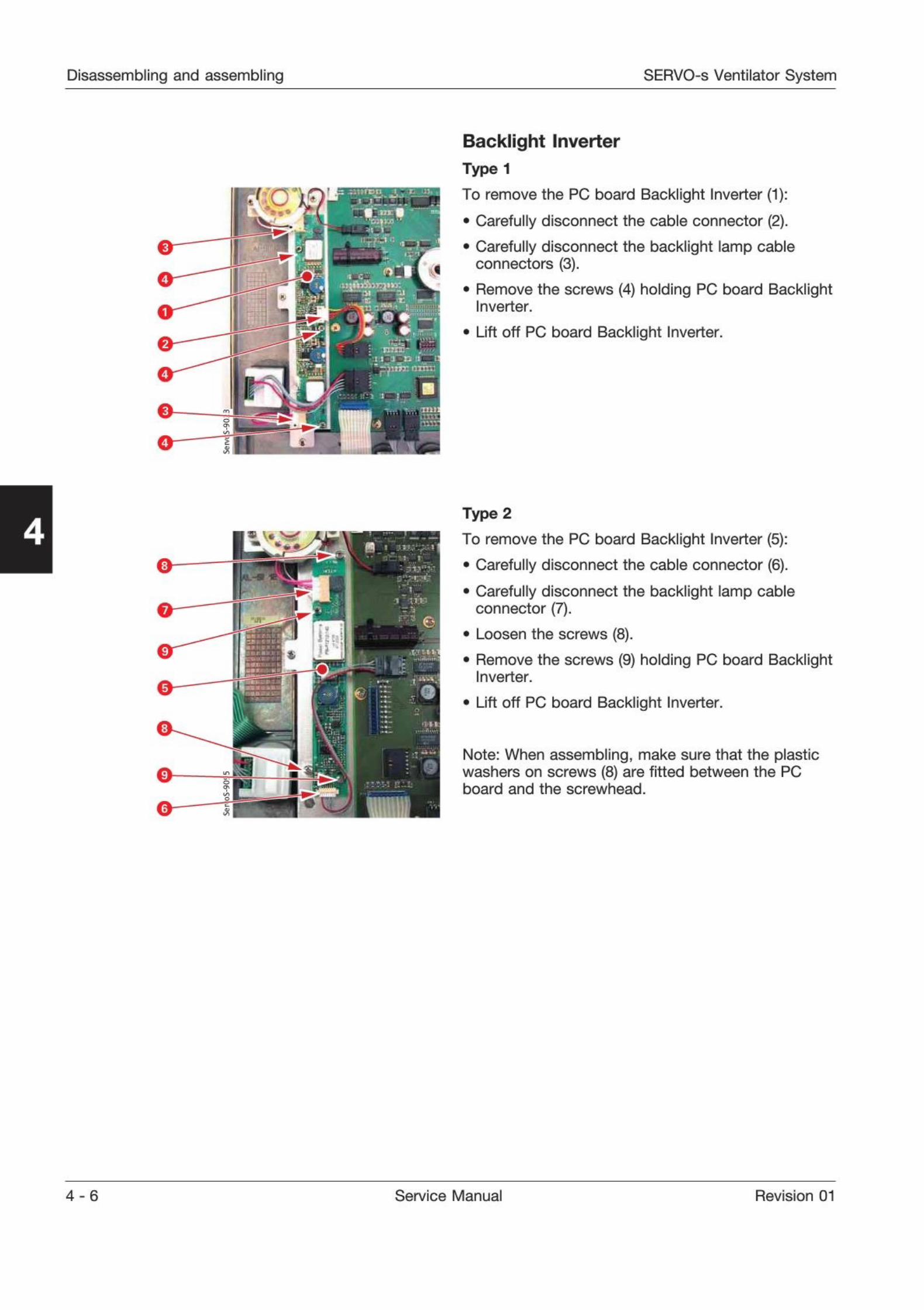
Backlight Inverter
Type 1
To remove the PC board Backlight Inverter (1):
. Carefully disconnect the cable connector (2).
. Carefully disconnect the backlight lamp cableconnectors (3).
. Remove the screws (4) holding PC board BacklightInverter.
Lift off PC board Backlight Inverter.
4
.a
I
ft5
Type 2
To remove the PC board Backlight Inverter (5):
. Carefully disconnect the cable connector (6).
. Carefully disconnect the backlight lamp cableconnector (7).
. Loosen the screws (8).
. Remove the screws (9) holding PC board BacklightInverter.
Lift off PC board Backlight Inverter.
Note: When assembling, make sure that the plasticwashers on screws (8) are fitted between the PCboard and the screwhead.
4 - 6 Service Manual Revision 01
SERVO-s Ventilator System Disassembling and assembling
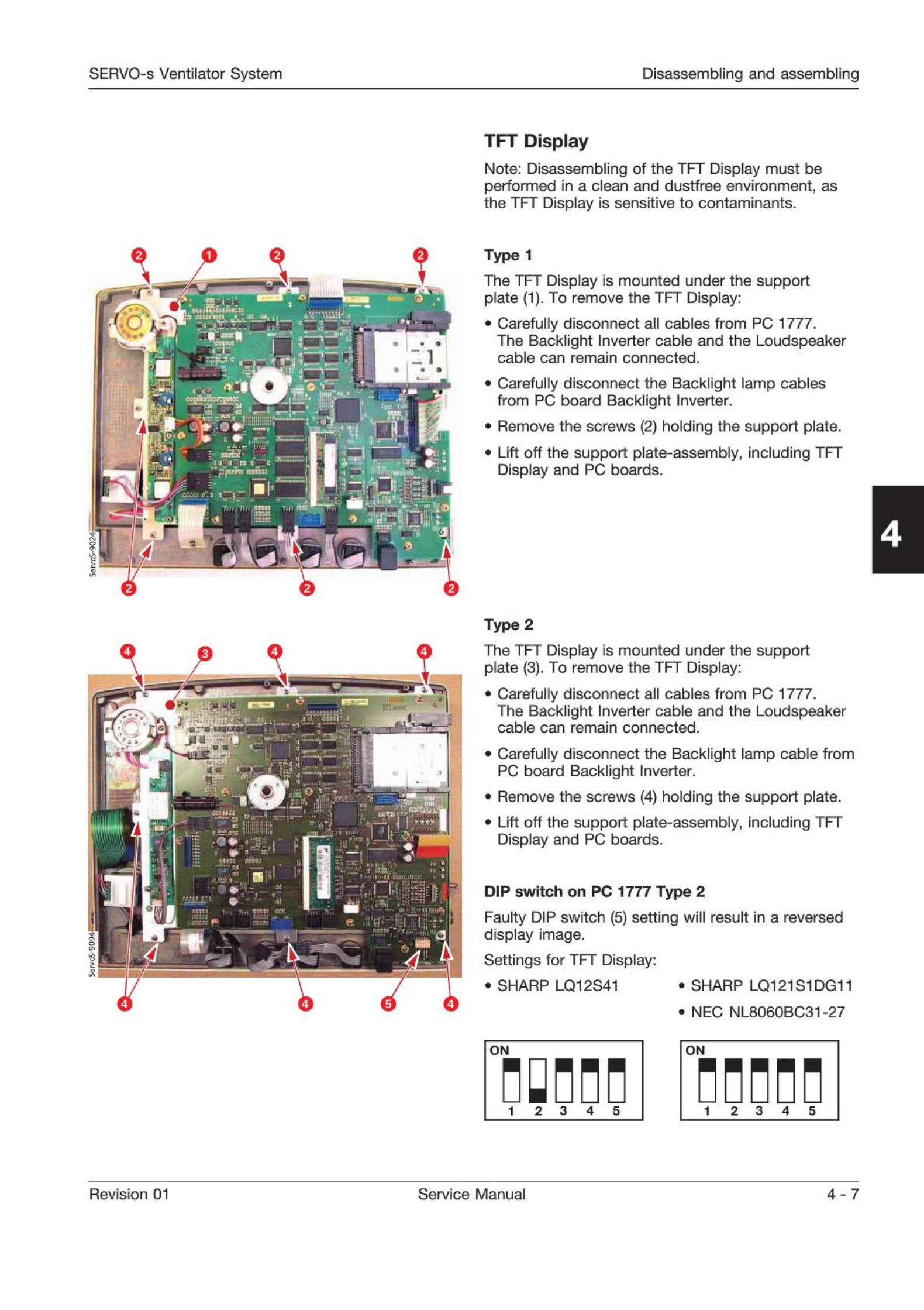
TFT Display
Note: Disassembling of the TFT Display must beperformed in a clean and dustfree environment, asthe TFT Display is sensitive to contaminants.
r
v
r
Type 1
The TFT Display is mounted under the supportplate (1). To remove the TFT Display:
Carefully disconnect all cables from PC 1777.The Backlight Inverter cable and the Loudspeakercable can remain connected.
Carefully disconnect the Backlight lamp cablesfrom PC board Backlight Inverter.
Remove the screws (2) holding the support plate.
Lift off the support plate-assembly, including TFTDisplay and PC boards.
4
Type 2
-
U -
1
A«
1
The TFT Display is mounted under the supportplate (3). To remove the TFT Display:
. Carefully disconnect all cables from PC 1777.
« The Backlight Inverter cable and the Loudspeakercable can remain connected.
. Carefully disconnect the Backlight lamp cable fromPC board Backlight Inverter.
. Remove the screws (4) holding the support plate.
. Lift off the support plate-assembly, including TFTDisplay and PC boards.
DIP switch on PC 1777 Type 2
Faulty DIP switch (5) setting will result in a reverseddisplay image.
Settings for TFT Display:
. SHARP LQ12S41 . SHARP LQ121S1DG11
. NEC NL8060BC31-27
ON
i 2 3 4 5
ON
nnnnn1 2 3 4 5
Revision 01 Service Manual 4 - 7
Disassembling and assembling SERVO-s Ventilator System
!
3
j<
>
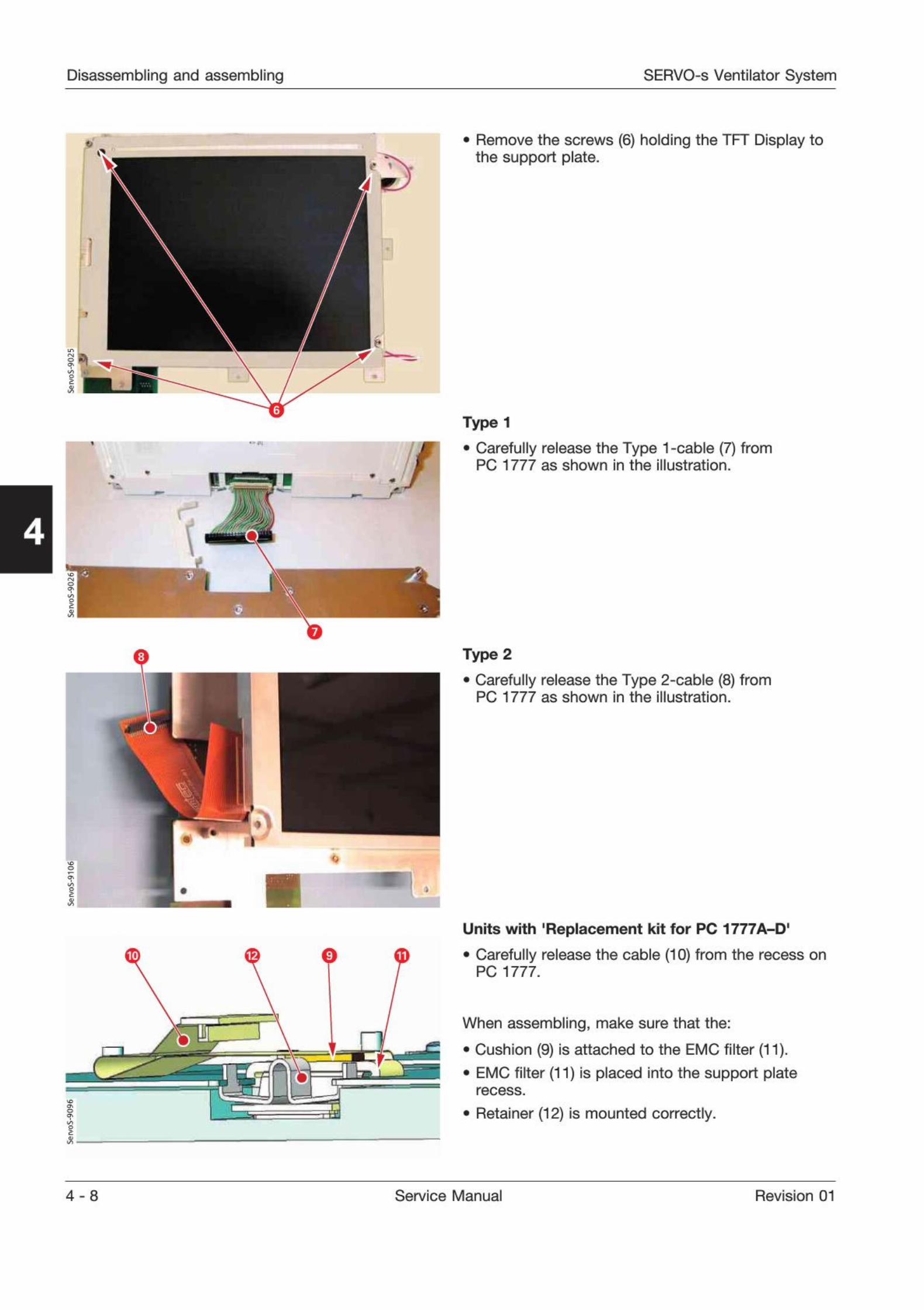
. Remove the screws (6) holding the TFT Display tothe support plate.
4r
1
\
/a
o
1
Type 1
Carefully release the Type 1-cable (7) fromPC 1777 as shown in the illustration.
Type 2
. Carefully release the Type 2-cable (8) fromPC 1777 as shown in the illustration.
Units with 'Replacement kit for PC 1TTTA-D'
. Carefully release the cable (10) from the recess onPC 1777.
When assembling, make sure that the:
. Cushion (9) is attached to the EMC filter (11).
. EMC filter (11) is placed into the support platerecess.
. Retainer (12) is mounted correctly.
4 - 8 Service Manual Revision 01
SERVO-s Ventilator System Disassembling and assembling
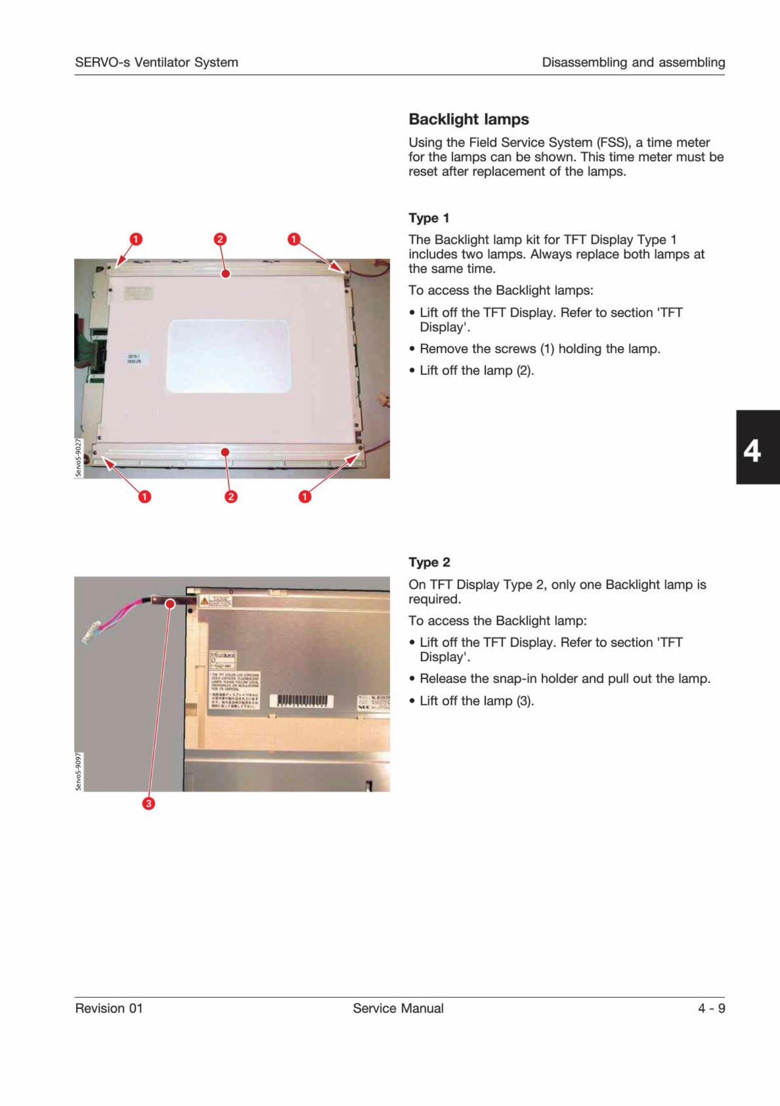
Backlight lamps
Using the Field Service System (FSS), a time meterfor the lamps can be shown. This time meter must bereset after replacement of the lamps.
--
Type 1
The Backlight lamp kit for TFT Display Type 1includes two lamps. Always replace both lamps atthe same time.
To access the Backlight lamps:
. Lift off the TFT Display. Refer to section TFT
Display'.
. Remove the screws (1) holding the lamp.
. Lift off the lamp (2).
4
1
ft
'. > X* J"
HUIMIIIIIII 1. . .l
\* *
1
Type 2
On TFT Display Type 2, only one Backlight lamp isrequired.
To access the Backlight lamp:
. Lift off the TFT Display. Refer to section TFT
Display'.
. Release the snap-in holder and pull out the lamp.
. Lift off the lamp (3).
Revision 01 Service Manual 4 - 9
Disassembling and assembling SERVO-s Ventilator System
4
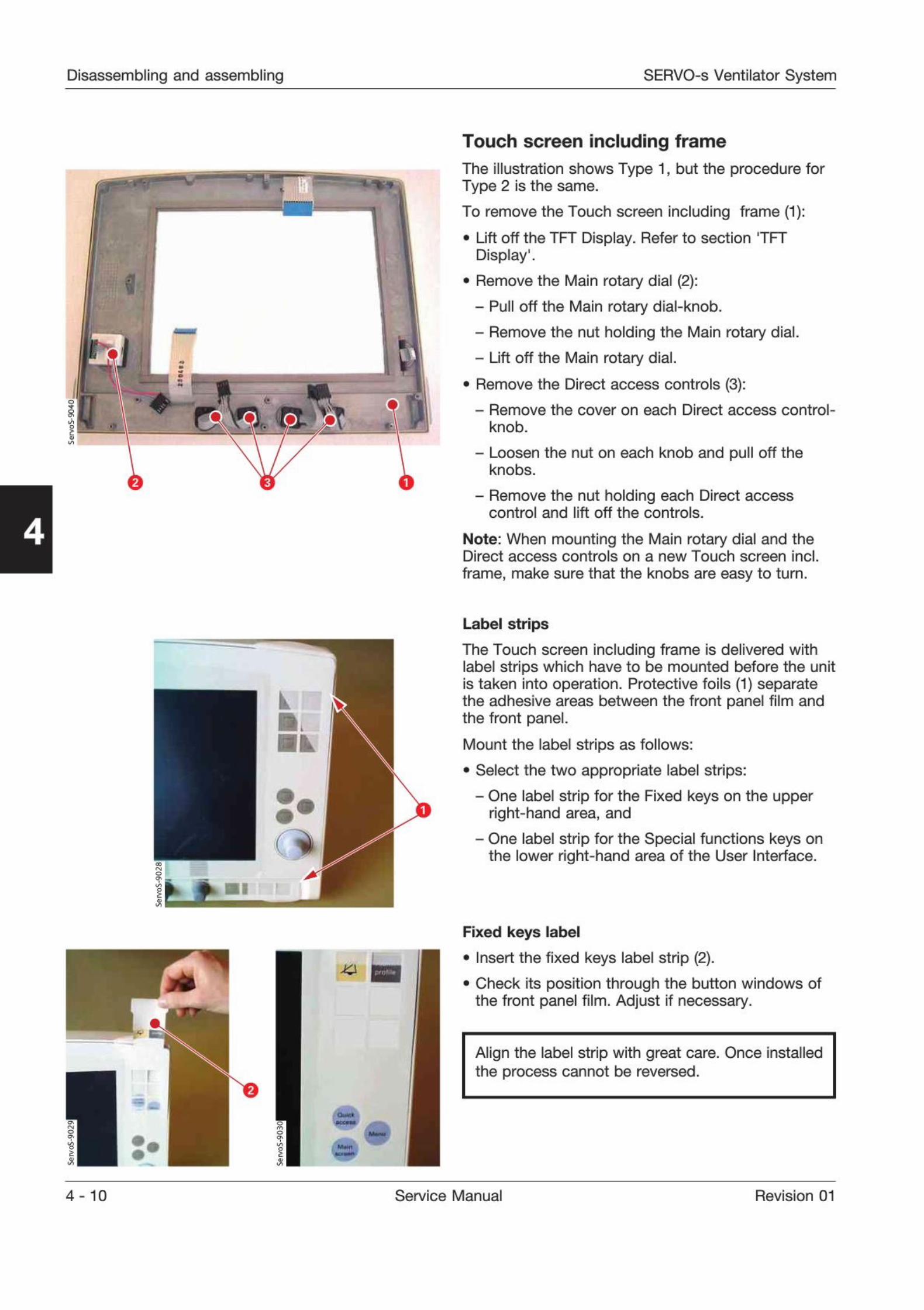
Touch screen including frame
The illustration shows Type 1, but the procedure forType 2 is the same.
To remove the Touch screen including frame (1):
. Lift off the TFT Display. Refer to section TFT
Display1.
. Remove the Main rotary dial (2):- Pull off the Main rotary dial-knob.- Remove the nut holding the Main rotary dial.- Lift off the Main rotary dial.
. Remove the Direct access controls (3):- Remove the cover on each Direct access control-
knob.
- Loosen the nut on each knob and pull off theknobs.
- Remove the nut holding each Direct accesscontrol and lift off the controls.
Note: When mounting the Main rotary dial and theDirect access controls on a new Touch screen incl.
frame, make sure that the knobs are easy to turn.
L
>
Label strips
The Touch screen including frame is delivered withlabel strips which have to be mounted before the unitis taken into operation. Protective foils (1) separatethe adhesive areas between the front panel film andthe front panel.
Mount the label strips as follows:
. Select the two appropriate label strips:- One label strip for the Fixed keys on the upper
right-hand area, and- One label strip for the Special functions keys on
the lower right-hand area of the User Interface.
9
Fixed keys label
. Insert the fixed keys label strip (2).
. Check its position through the button windows ofthe front panel film. Adjust if necessary.
Align the label strip with great care. Once installedthe process cannot be reversed.
4-10 Service Manual Revision 01
SERVO-s Ventilator System Disassembling and assembling
i>:
1
l 3
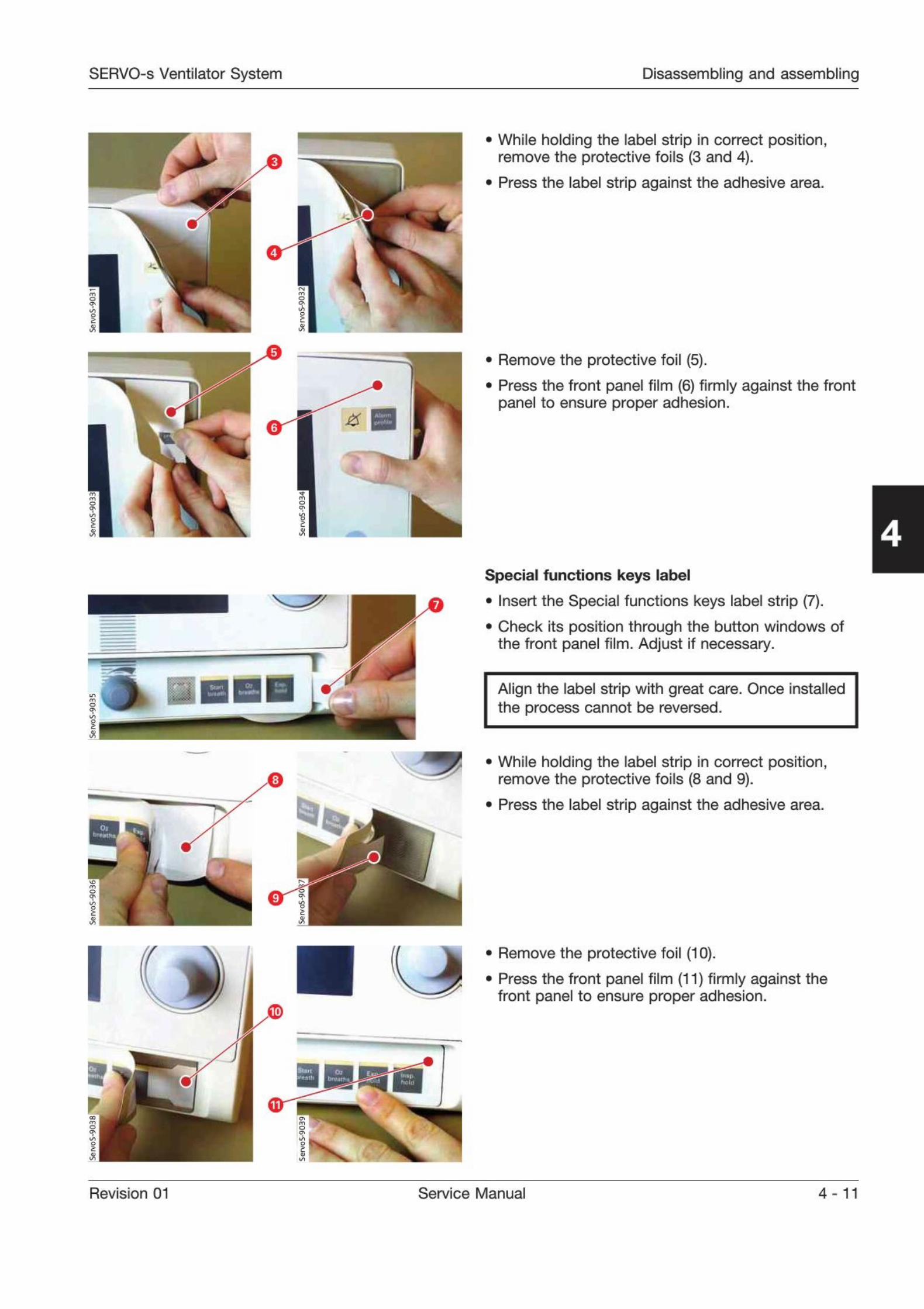
While holding the label strip in correct position,remove the protective foils (3 and 4).
Press the label strip against the adhesive area.
. Remove the protective foil (5).
. Press the front panel film (6) firmly against the frontpanel to ensure proper adhesion.
4
Bj
ft
5
Special functions keys label
. Insert the Special functions keys label strip (7).
. Check its position through the button windows ofthe front panel film. Adjust if necessary.
Align the label strip with great care. Once installedthe process cannot be reversed.
While holding the label strip in correct position,remove the protective foils (8 and 9).
Press the label strip against the adhesive area.
Remove the protective foil (10).
Press the front panel film (11) firmly against thefront panel to ensure proper adhesion.
Revision 01 Service Manual 4 -11
Disassembling and assembling SERVO-s Ventilator System
4
Release
90°
Locko
'1
o
:
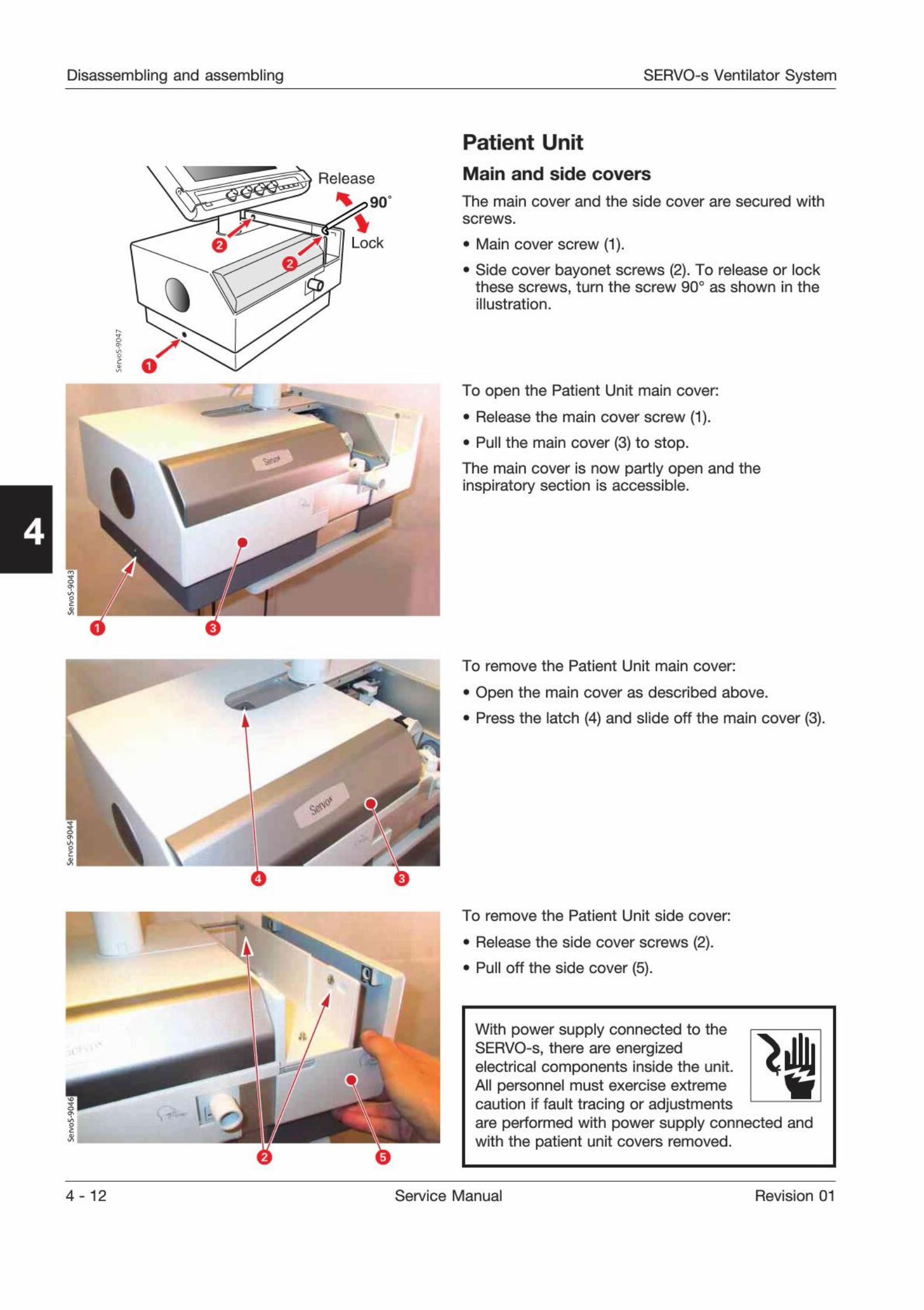
Patient Unit
Main and side covers
The main cover and the side cover are secured with
screws.
Main cover screw (1).
. Side cover bayonet screws (2). To release or lock
these screws, turn the screw 90° as shown in the
illustration.
To open the Patient Unit main cover:
. Release the main cover screw (1).
. Pull the main cover (3) to stop.
The main cover is now partly open and theinspiratory section is accessible.
L
r
To remove the Patient Unit main cover:
. Open the main cover as described above.
. Press the latch (4) and slide off the main cover (3).
To remove the Patient Unit side cover:
. Release the side cover screws (2).
. Pull off the side cover (5).
With power supply connected to theSERVO-s, there are energizedelectrical components inside the unit.All personnel must exercise extremecaution if fault tracing or adjustmentsare performed with power supply connected andwith the patient unit covers removed.
4- 12 Service Manual Revision 01
SERVO-s Ventilator System Disassembling and assembling
9 4
faI
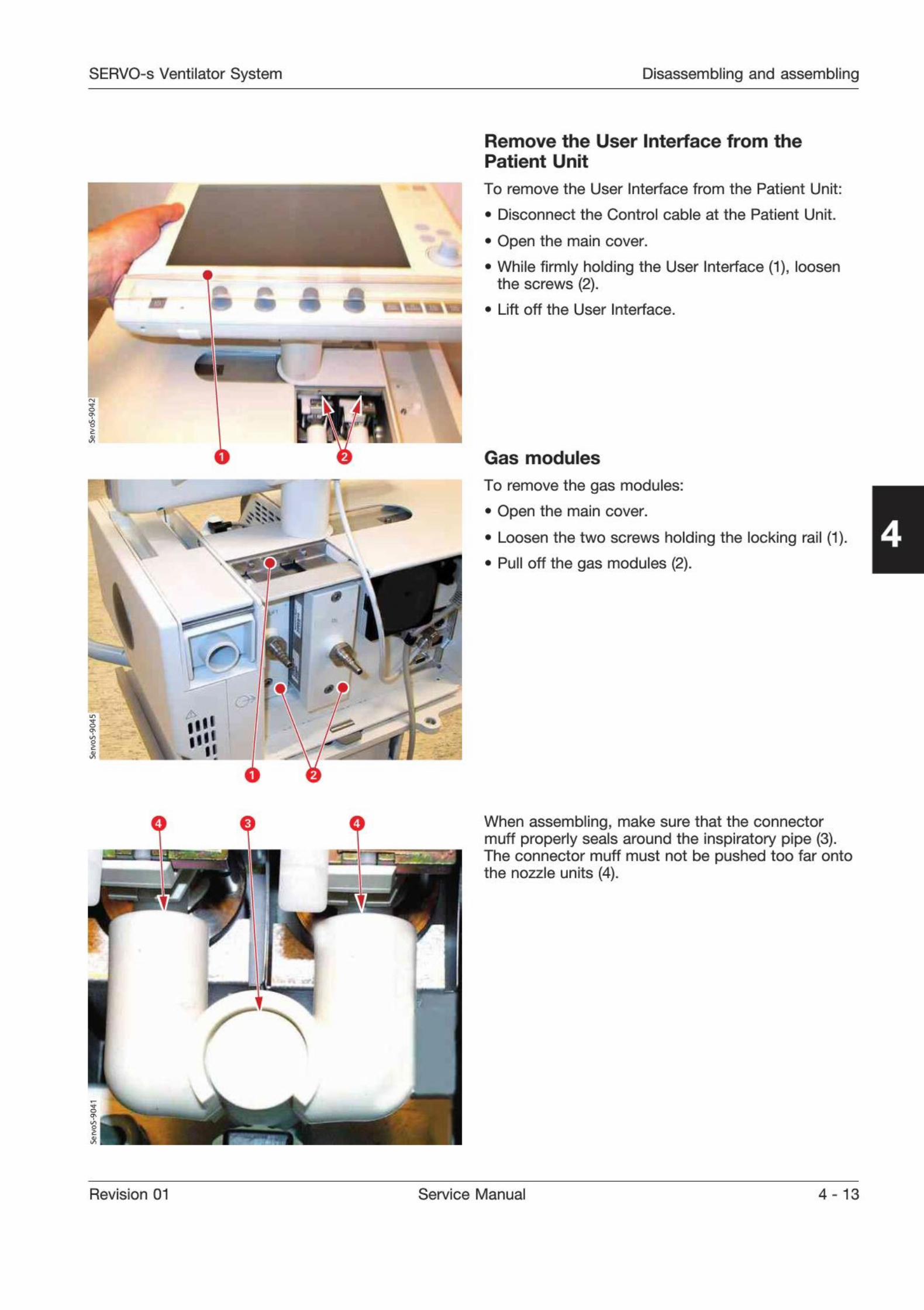
Remove the User Interface from thePatient Unit
To remove the User Interface from the Patient Unit:
. Disconnect the Control cable at the Patient Unit.
. Open the main cover.
While firmly holding the User Interface (1), loosenthe screws (2).
. Lift off the User Interface.
0
t
r
il
Gas modules
To remove the gas modules:
. Open the main cover.
. Loosen the two screws holding the locking rail (1).
. Pull off the gas modules (2).
4
--
When assembling, make sure that the connectormuff properly seals around the inspiratory pipe (3).The connector muff must not be pushed too far ontothe nozzle units (4).
Revision 01 Service Manual 4 - 13
Disassembling and assembling SERVO-s Ventilator System
4
r
1
V
ihi
V
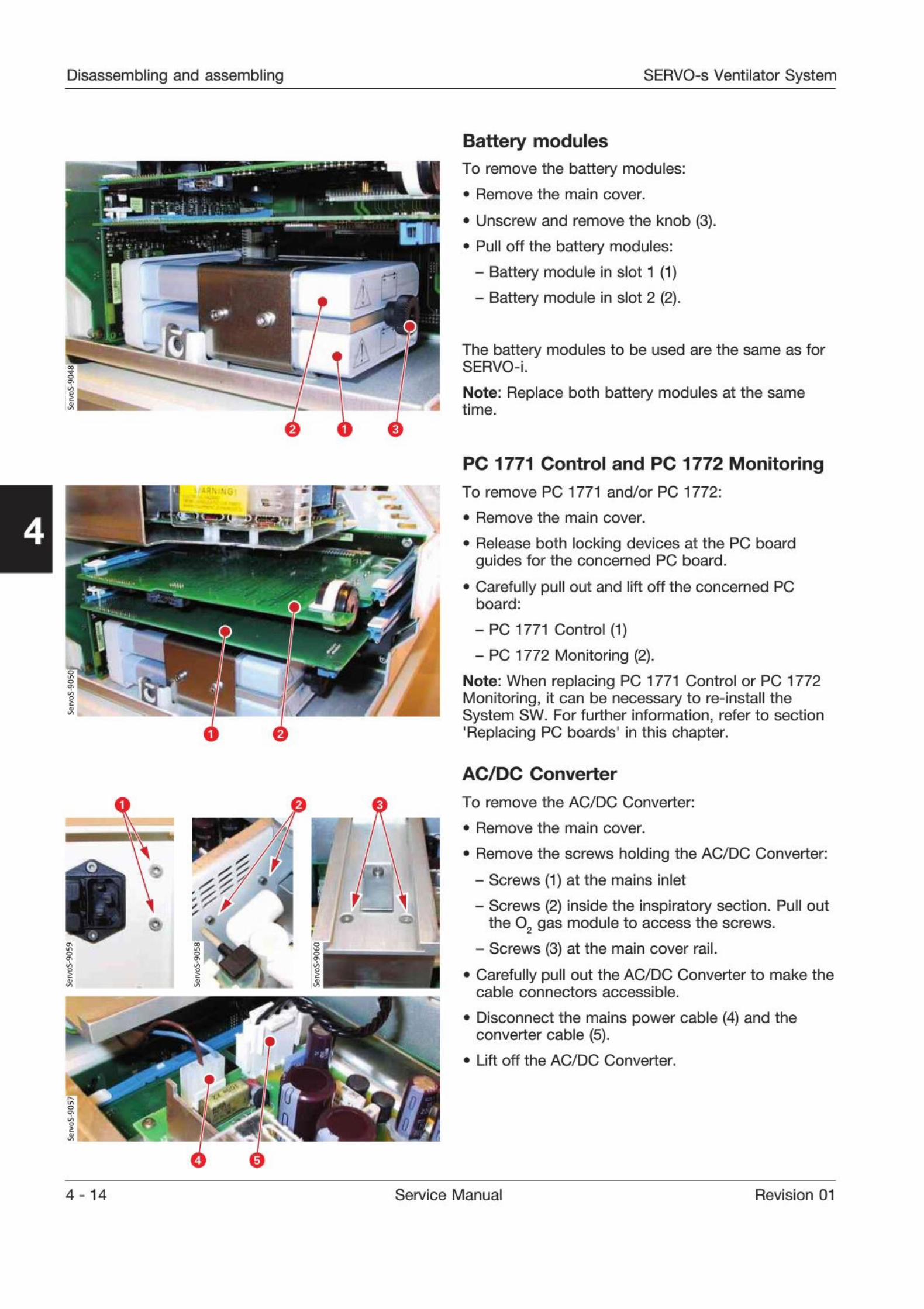
Battery modules
To remove the battery modules:
. Remove the main cover.
. Unscrew and remove the knob (3).
. Pull off the battery modules:- Battery module in slot 1 (1)- Battery module in slot 2 (2).
The battery modules to be used are the same as forSERVO-i.
Note: Replace both battery modules at the sametime.
PC 1771 Control and PC 1772 Monitoring
To remove PC 1771 and/or PC 1772:
. Remove the main cover.
. Release both locking devices at the PC boardguides for the concerned PC board.
. Carefully pull out and lift off the concerned PCboard:
- PC 1771 Control (1)- PC 1772 Monitoring (2).
Note: When replacing PC 1771 Control or PC 1772Monitoring, it can be necessary to re-install theSystem SW. For further information, refer to section'
Replacing PC boards' in this chapter.
AC/DC Converter
To remove the AC/DC Converter:
. Remove the main cover.
. Remove the screws holding the AC/DC Converter:
- Screws (1) at the mains inlet- Screws (2) inside the inspiratory section. Pull out
the 02 gas module to access the screws.
- Screws (3) at the main cover rail.
. Carefully pull out the AC/DC Converter to make thecable connectors accessible.
. Disconnect the mains power cable (4) and theconverter cable (5).
. Lift off the AC/DC Converter.
4-14 Service Manual Revision 01
SERVO-s Ventilator System Disassembling and assembling
_
-
4
ft .-J
-
;
:
ii
i
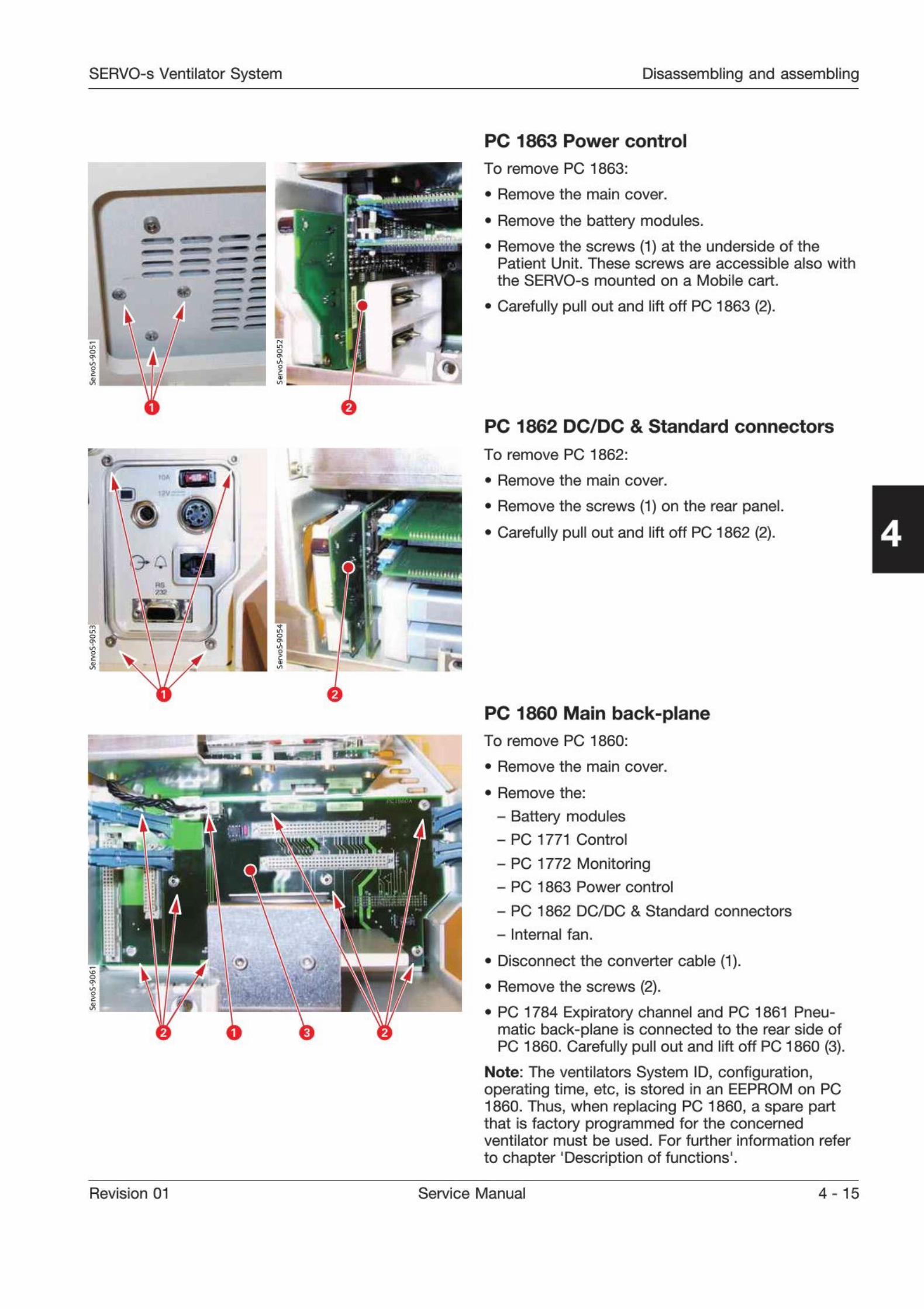
PC 1863 Power control
To remove PC 1863:
. Remove the main cover.
Remove the battery modules.
Remove the screws (1) at the underside of thePatient Unit. These screws are accessible also with
the SERVO-s mounted on a Mobile cart.
Carefully pull out and lift off PC 1863 (2).
PC 1862 DC/DC & Standard connectors
To remove PC 1862:
. Remove the main cover.
. Remove the screws (1) on the rear panel.
. Carefully pull out and lift off PC 1862 (2). 4
PC 1860 Main back-planeTo remove PC 1860:
. Remove the main cover.
. Remove the:
- Battery modules- PC 1771 Control
- PC 1772 Monitoring- PC 1863 Power control
- PC 1862 DC/DC & Standard connectors
- Internal fan.
. Disconnect the converter cable (1).
. Remove the screws (2).
. PC 1784 Expiratory channel and PC 1861 Pneu-matic back-plane is connected to the rear side ofPC 1860. Carefully pull out and lift off PC 1860 (3).
Note: The ventilators System ID, configuration,operating time, etc, is stored in an EEPROM on PC1860. Thus, when replacing PC 1860, a spare partthat is factory programmed for the concernedventilator must be used. For further information refer
to chapter 'Description of functions'.
Revision 01 Service Manual 4 - 15
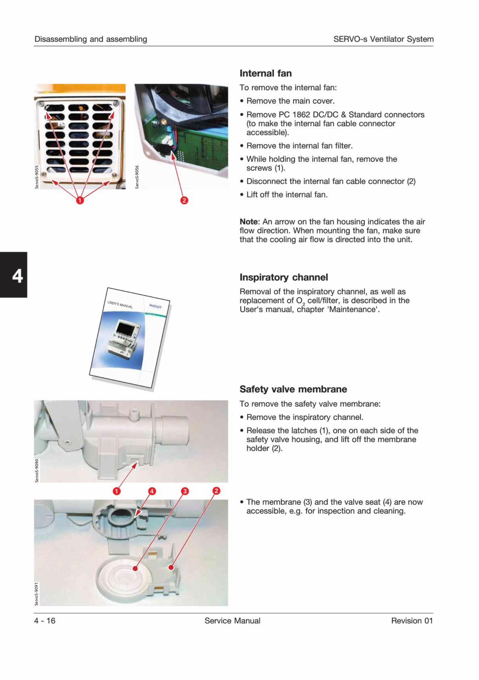
Disassembling and assembling SERVO-s Ventilator System
5
Internal fan
To remove the internal fan:
. Remove the main cover.
. Remove PC 1862 DC/DC & Standard connectors
(to make the internal fan cable connectoraccessible).
. Remove the internal fan filter.
. While holding the internal fan, remove the
screws (1).
. Disconnect the internal fan cable connector (2)
. Lift off the internal fan.
Note: An arrow on the fan housing indicates the airflow direction. When mounting the fan, make surethat the cooling air flow is directed into the unit.
4
noun
7
7
Inspiratory channel
Removal of the inspiratory channel, as well asreplacement of 02
cell/filter, is described in theUser's manual, chapter 'Maintenance1.
i
si
Safety valve membrane
To remove the safety valve membrane:
. Remove the inspiratory channel.
. Release the latches (1), one on each side of the
safety valve housing, and lift off the membraneholder (2).
. The membrane (3) and the valve seat (4) are nowaccessible, e.g. for inspection and cleaning.
4-16 Service Manual Revision 01
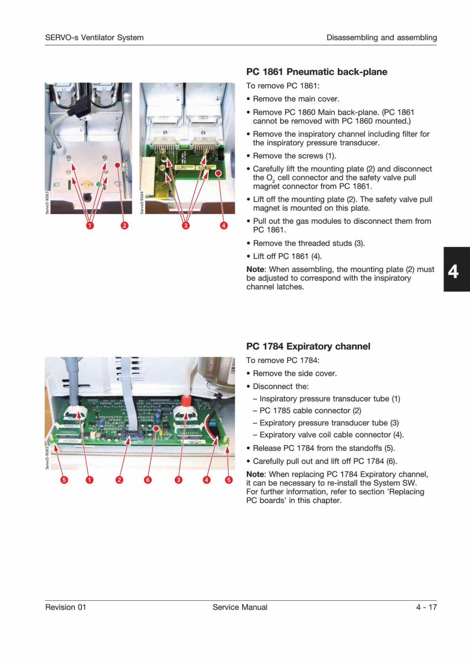
SERVO-s Ventilator System Disassembling and assembling
i
»
m
rTTTTTTTTl
n
11
PC 1861 Pneumatic back-planeTo remove PC 1861:
. Remove the main cover.
. Remove PC 1860 Main back-plane. (PC 1861cannot be removed with PC 1860 mounted.)
. Remove the inspiratory channel including filter forthe inspiratory pressure transducer.
. Remove the screws (1).
Carefully lift the mounting plate (2) and disconnectthe 0
2 cell connector and the safety valve pullmagnet connector from PC 1861.
. Lift off the mounting plate (2). The safety valve pullmagnet is mounted on this plate.
. Pull out the gas modules to disconnect them fromPC 1861.
. Remove the threaded studs (3).
. Liftoff PC 1861 (4).
Note: When assembling, the mounting plate (2) mustbe adjusted to correspond with the inspiratorychannel latches.
4
o
PC 1784 Expiratory channel- To remove PC 1784:
m
a . Remove the side cover.
. Disconnect the:
- Inspiratory pressure transducer tube (1)- PC 1785 cable connector (2)- Expiratory pressure transducer tube (3)- Expiratory valve coil cable connector (4).
. Release PC 1784 from the standoffs (5).
. Carefully pull out and lift off PC 1784 (6).
Note: When replacing PC 1784 Expiratory channel,it can be necessary to re-install the System SW.For further information, refer to section 'ReplacingPC boards' in this chapter.
Revision 01 Service Manual 4 - 17
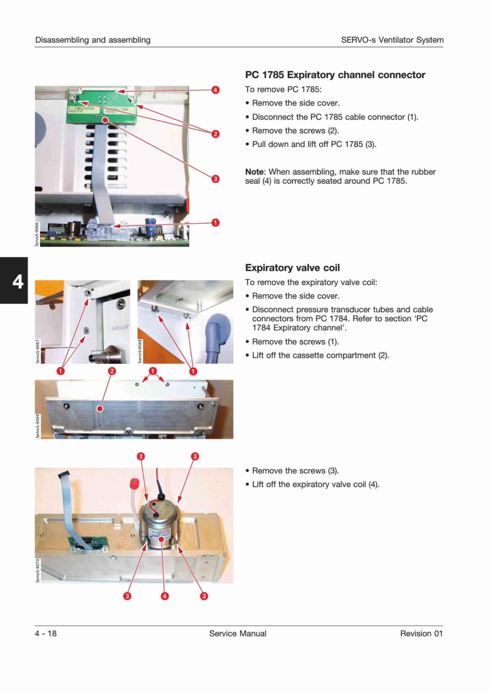
Disassembling and assembling SERVO-s Ventilator System
O
m 1
PC 1785 Expiratory channel connectorTo remove PC 1785:
. Remove the side cover.
. Disconnect the PC 1785 cable connector (1).
. Remove the screws (2).
. Pull down and lift off PC 1785 (3).
Note: When assembling, make sure that the rubberseal (4) Is correctly seated around PC 1785.
4
!-
1- -
2
8
Expiratory valve coil
To remove the expiratory valve coil:
. Remove the side cover.
. Disconnect pressure transducer tubes and cableconnectors from PC 1784. Refer to section 'PC
1784 Expiratory channel1.
. Remove the screws (1).
. Lift off the cassette compartment (2).
.
11
. Remove the screws (3).
. Lift off the expiratory valve coil (4).
4-18 Service Manual Revision 01
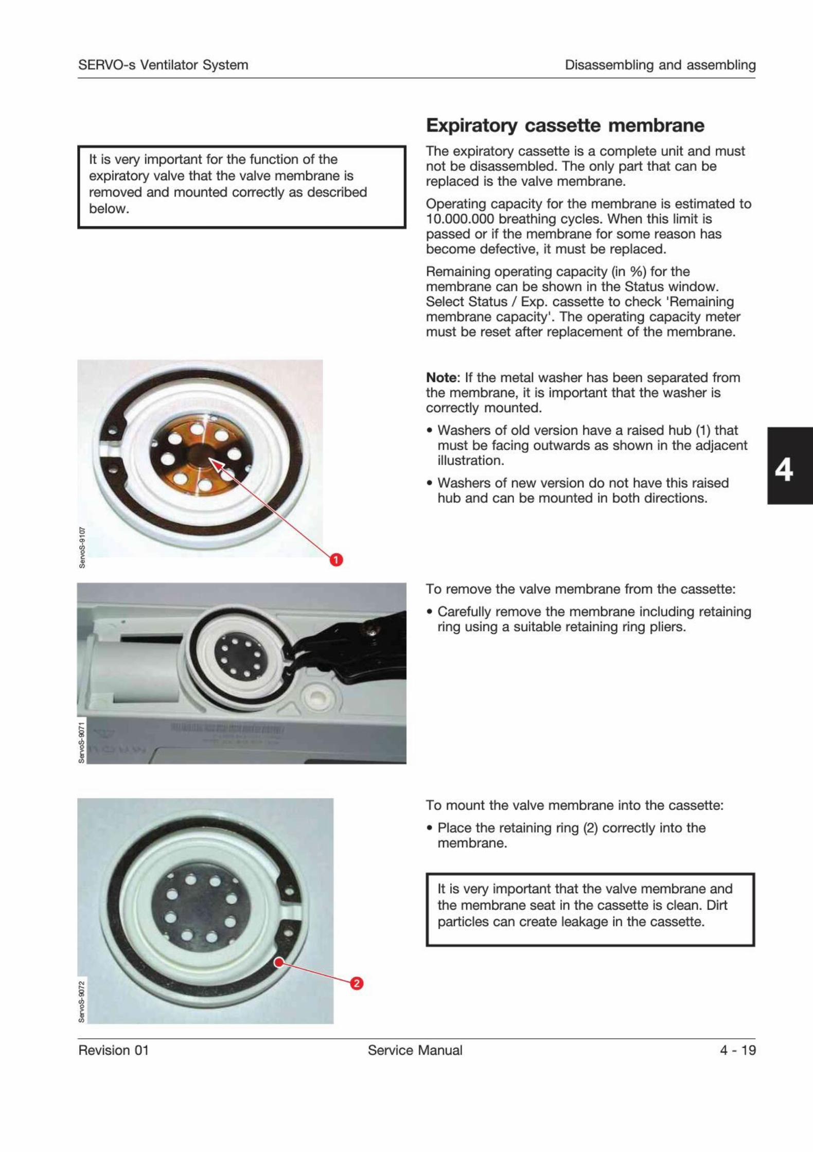
SERVO-s Ventilator System Disassembling and assembling
It is very important for the function of theexpiratory valve that the valve membrane isremoved and mounted correctly as describedbelow.
Expiratory cassette membraneThe expiratory cassette is a complete unit and mustnot be disassembled. The only part that can bereplaced is the valve membrane.
Operating capacity for the membrane is estimated to10.000.000 breathing cycles. When this limit ispassed or if the membrane for some reason hasbecome defective, it must be replaced.
Remaining operating capacity (In %) for themembrane can be shown in the Status window.
Select Status / Exp. cassette to check 'Remainingmembrane capacity
1
. The operating capacity metermust be reset after replacement of the membrane.
5
5
Note: If the metal washer has been separated fromthe membrane, it is important that the washer iscorrectly mounted.
. Washers of old version have a raised hub (1) thatmust be facing outwards as shown in the adjacentillustration.
. Washers of new version do not have this raised
hub and can be mounted in both directions.
4
To remove the valve membrane from the cassette:
. Carefully remove the membrane including retainingring using a suitable retaining ring pliers.
To mount the valve membrane into the cassette:
. Place the retaining ring (2) correctly into themembrane.
It is very important that the valve membrane andthe membrane seat in the cassette is clean. Dirt
particles can create leakage in the cassette.
Revision 01 Service Manual 4 - 19

Disassembling and assembling SERVO-s Ventilator System
. Place the membrane onto the cassette as shown in
the illustration.
4
Squeeze the retaining ring pliers and carefullypress the membrane in place into the cassette asshown in the illustration.
.
5
. Carefully release and remove the pliers.
. Check that the membrane is not deformed by theretaining ring. If necessary, remove the membraneand redo the complete mounting procedure.
. Mount the expiratory cassette onto the PatientUnit.
. Reset the operating capacity meter afterreplacement of the membrane. To access the resetbutton, select Menu / Biomed / Service.
m
Control cable
The control cable connectors must be connected
carefully to avoid damages on the connector pins.
. Carefully find the correct position; the connectorpins and the guides in the connectors mustcorrespond. Do not turn the connector whileinserting!
. When correct position is found, insert the
connector.
Secure the connector with its locking ring.
The illustration shows the Patient Unit connector, but
the procedure for the User Interface connector is thesame.
Note: The Control cable must only be connected ordisconnected when the ventilator is switched Off.
4-20 Service Manual Revision 01
SERVO-s Ventilator System Service procedures
Only personnel trained and authorizedby MAQUET shall be permitted toperform installation, service ormaintenance of the SERVO-s.
Make sure to prepare the SERVO-s properlybefore disassembling and assembling. Refer tosection 'Hazard notices' in chapter 'Important'.
Any service or maintenance must be noted in alog book.
After any installation, maintenance or serviceintervention in the SERVO-s, perform a 'Pre-usecheck'
. Refer to the 'SERVO-s Ventilator System- User's Manual' for details.
This product contains electronic andelectrical components. Discarddisposable, replaced and left-over partsin accordance with appropriateindustrial and environmental standards.
5. Service procedures
Battery modules 5-2
Replacing the lithium batteries onPC 1771 and PC 1772 5-3
Using the Menu and Biomed key 5-4
Menu 5-4
Biomed 5-4
Software installation 5-6
General 5-6
Software information 5-6
Software delivery 5-6
Software installation procedure 5-6
Field Service System 5-6
General 5-6
Field Service System functions 5-6
Revision 01 Service Manual 5-1
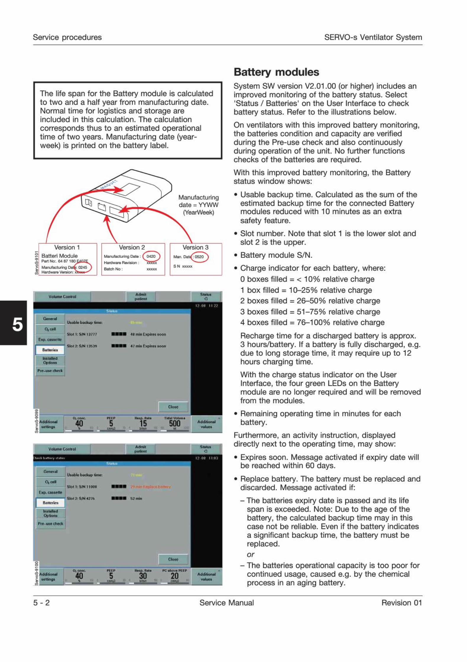
Service procedures SERVO-s Ventilator System
The life span for the Battery module is calculatedto two and a half year from manufacturing date.Normal time for logistics and storage areincluded in this calculation. The calculation
corresponds thus to an estimated operationaltime of two years. Manufacturing date (year-week) is printed on the battery label.
3.
C3Manufacturingdate = YYWW
(YearWeek)
Version 1
Batten ModulePart No:. 64 87 180 EtfOZE
Manufacturing Dafe 0245 JHardware Versmn: xfewt
Version 2
Manufacturing Date ;Hardware Revision;
Batch No:
(0420)XX XXX
Version 3
Man. Dat QS T)S N xxxxx
Sl0II:SWI3777
slnl ' SN i I',
4« miiiloptipc toon
4 / mm ('
.pur i toon
LJlllltllti
kuttiadOption.
ClOM
O. ..0«. I-II p
40 5 500157-
% Addibond
AHrmi
MiliMiVolume Conirol
Undbic backup tma
Slot l:SJN HOOT
K3 m»»
Pie oMch*ek
I i'
40 5 20E
Battery modulesSystem SW version V2.01.00 (or higher) includes animproved monitoring of the battery status. Select'Status / Batteries' on the User Interface to check
battery status. Refer to the illustrations below.
On ventilators with this improved battery monitoring,the batteries condition and capacity are verifiedduring the Pre-use check and also continuouslyduring operation of the unit. No further functionschecks of the batteries are required.
With this improved battery monitoring, the Batterystatus window shows:
. Usable backup time. Calculated as the sum of the
estimated backup time for the connected Batterymodules reduced with 10 minutes as an extra
safety feature.
. Slot number. Note that slot 1 is the lower slot and
slot 2 is the upper.
. Battery module S/N.
. Charge indicator for each battery, where:
0 boxes filled = < 10% relative charge
1 box filled = 10-25% relative charge2 boxes filled = 26-50% relative charge
3 boxes filled = 51-75% relative charge4 boxes filled = 76-100% relative charge
Recharge time for a discharged battery is approx.3 hours/battery. If a battery is fully discharged, e.g.due to long storage time, it may require up to 12hours charging time.
With the charge status indicator on the UserInterface, the four green LEDs on the Batterymodule are no longer required and will be removedfrom the modules.
. Remaining operating time in minutes for eachbattery.
Furthermore, an activity instruction, displayeddirectly next to the operating time, may show:
. Expires soon. Message activated if expiry date willbe reached within 60 days.
. Replace battery. The battery must be replaced anddiscarded. Message activated if:- The batteries expiry date is passed and its life
span is exceeded. Note: Due to the age of thebattery, the calculated backup time may in thiscase not be reliable. Even if the battery indicatesa significant backup time, the battery must bereplaced.or
- The batteries operational capacity is too poor forcontinued usage, caused e.g. by the chemicalprocess in an aging battery.
5 - 2 Service Manual Revision 01

SERVO-s Ventilator System Service procedures
Replacing the lithium batteries onPC 1771 and PC 1772
The lithium batteries must be replaced after 5 years.A Technical error message will appear on the screenif the battery voltage level is too low.
Always replace both batteries at the same time tokeep the same replacement date for both batteries.
Preparations
. Set the On/Off switch on the control unit to Off.
. Disconnect the mains power cable.
. Disconnect the gas supplies (wall and/or cylinder).
. Remove patient tubing.
K3
5
]
Replacing the lithium battery
. The lithium batteries are mounted on ESD sensitive
PC boards. Refer to chapter 'Disassembling andassembling
1
, section 'Handling PC boards' forfurther information regarding ESD sensitivecomponents.
. Remove the Patient Unit main cover. Refer to
chapter '
Disassembling and assembling'.
. Carefully pull out PC 1771 and PC 1772.
Note: Do not remove the cable connector (1).Information stored in the PC board memory will beerased if the connector is removed:
- If the battery on PC 1771 is disconnected;user default configurations made via the FieldService System (FSS) and Pre-use check resultsincluding transducer calibrations will be erased.
- if the battery on PC 1772 is disconnected;all trends, all logs and Pre-use check resultsincluding transducer calibrations will be erased.
. There are two equal battery connectors (2 and 3)on the PC boards. Connect the new battery to theun-used connector. The memory functions are nowsecured by the new battery.
. Cut the cable ties holding the old battery (4) to thePC board.
Disconnect and remove the old battery.
. Mount the new battery onto the PC board usingnew cable ties as shown in the illustration.
. Insert the PC board into the correct PC-board slot
and reassemble the Patient Unit.
After any maintenance or service of the SERVO-s,perform a
'Pre-use check'. Refer to the 'SERVO-s
Ventilator System - User's manual'.
Revision 01 Service Manual 5-3
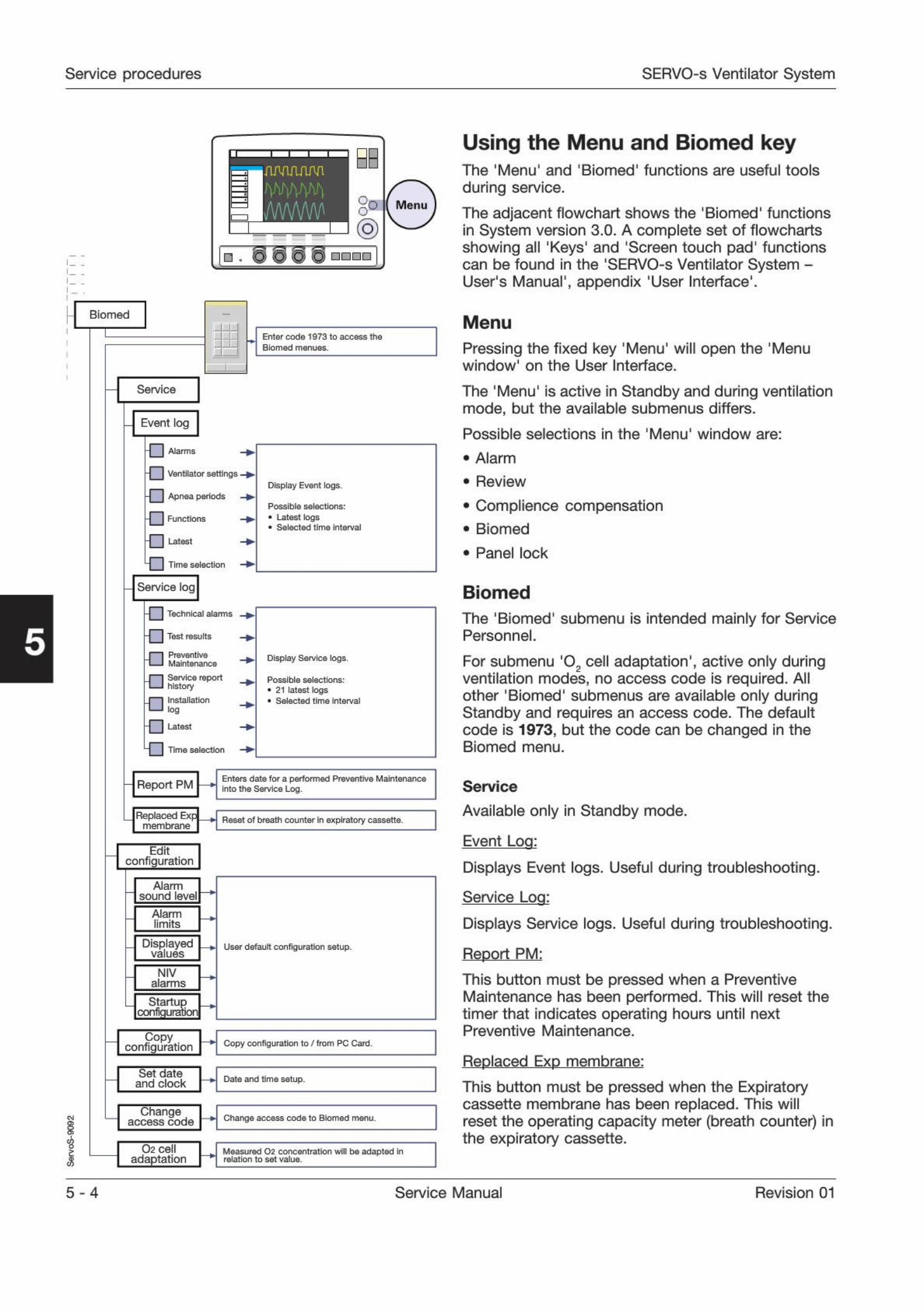
Service procedures SERVO-s Ventilator System
mm/www
c0
0
@ - O © O o
L Biomed
i
I
JJJEnter code 1973 to access the
Biomed menues.
Service
Event log
H | Alarms
-\ | Ventilator settings
-| | Apnea periods~] | Functions
H | Latest
] Time selection
Display Event logs*
Possible selections:
. Latest logs
. SelQCted time intorva!
Service log
4 | Technical alarms
H | Test results
J | Preventive1-1 Maintenance
I | Service reportI-I history
J I Installation1-I log
H | Utest
~| | Time selection
Display Service logs.
Possible selections:
. 21 latest logs SolDctDd time Interval
Report PMEnters date for a performed Preventive Maintenanceinto the Service Log
Replaced Expmembrane
Reset o( breath counter in expiratory cassette.
Editconfiguration
Alarmsound level
Alarmlimits
Displayedvalues
NIValarms
Startupconfiguration
User default configuration setup.
Copyconfiguration Copy configuration to / from PC Card
Set dateand clock Dale and time setup.
Changeaccess code Change access code to Biomed menu.
O2 celladaptation
Measured 02 concentration will be adapted Inrelation to set value.
Using the Menu and Biomed keyThe 'Menu' and 'Biomed' functions are useful tools
during service.
The adjacent flowchart shows the 'Biomed' functionsin System version 3.0. A complete set of flowchartsshowing all
'
Keys' and 'Screen touch pad' functionscan be found in the 'SERVO-s Ventilator System -User's Manual', appendix 'User Interface'.
Menu
Pressing the fixed key 'Menu' will open the 'Menuwindow' on the User Interface.
The 'Menu' is active in Standby and during ventilationmode, but the available submenus differs.
Possible selections In the 'Menu' window are:
. Alarm
. Review
. Complience compensation
. Biomed
. Panel lock
Biomed
The 'Biomed' submenu is intended mainly for ServicePersonnel.
For submenu '02 cell adaptation', active only during
ventilation modes, no access code is required. Allother 'Biomed' submenus are available only duringStandby and requires an access code. The defaultcode is 1973, but the code can be changed in theBiomed menu.
Service
Available only in Standby mode.
Event Log:
Displays Event logs. Useful during troubleshooting.
Service Log:
Displays Service logs. Useful during troubleshooting.
Report PM:
This button must be pressed when a PreventiveMaintenance has been performed. This will reset thetimer that indicates operating hours until nextPreventive Maintenance.
Replaced Exp membrane:
This button must be pressed when the Expiratorycassette membrane has been replaced. This willreset the operating capacity meter (breath counter) Inthe expiratory cassette.
5-4 Service Manual Revision 01
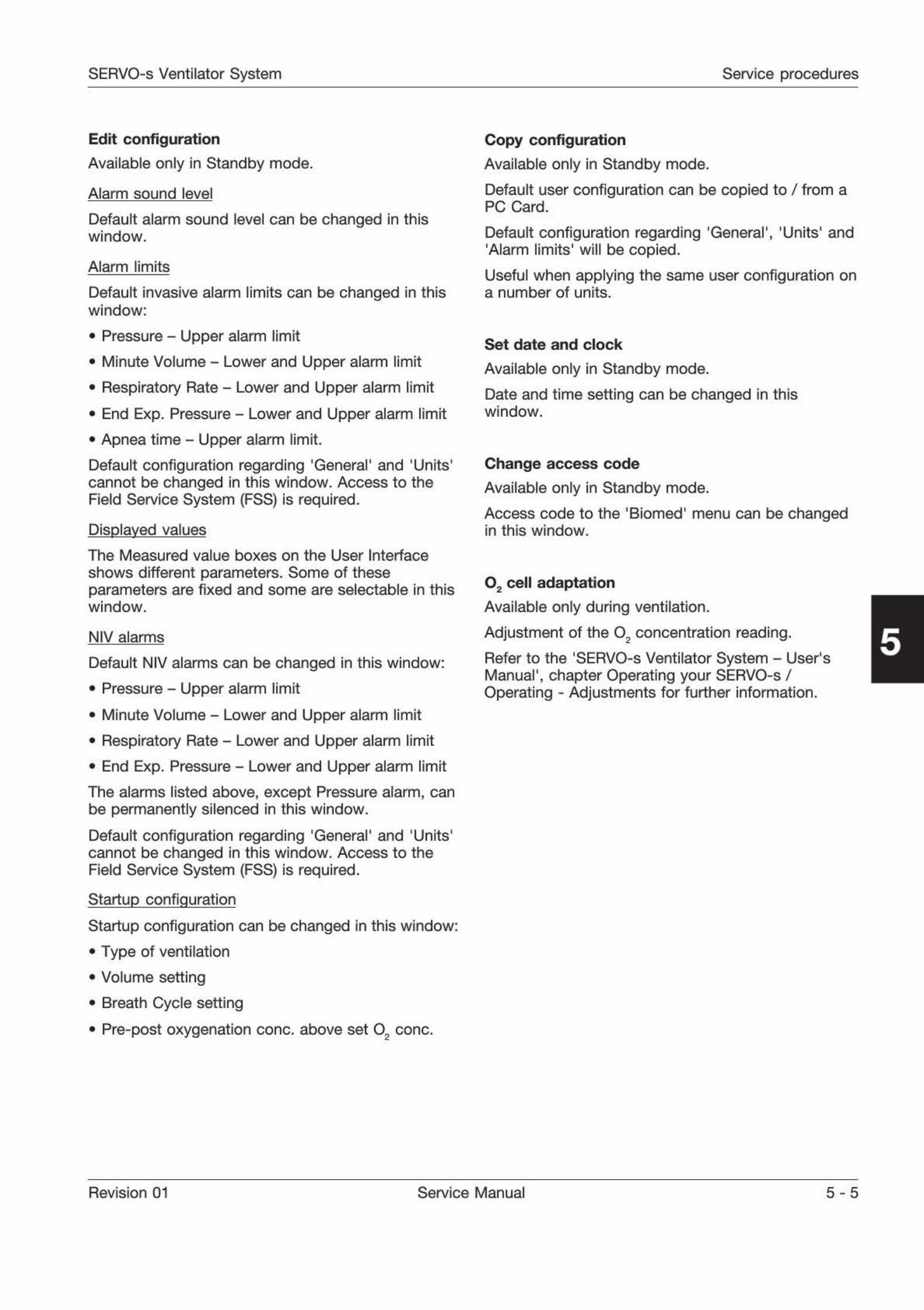
SERVO-s Ventilator System Service procedures
Edit configuration
Available only in Standby mode.
Alarm sound level
Default alarm sound level can be changed in thiswindow.
Alarm limits
Default invasive alarm limits can be changed in thiswindow:
. Pressure - Upper alarm limit
. Minute Volume - Lower and Upper alarm limit
. Respiratory Rate - Lower and Upper alarm limit
. End Exp. Pressure - Lower and Upper alarm limit
. Apnea time - Upper alarm limit.
Default configuration regarding 'General' and 'Units'cannot be changed in this window. Access to theField Service System (FSS) is required.
Displayed values
The Measured value boxes on the User Interface
shows different parameters. Some of theseparameters are fixed and some are selectable in thiswindow.
NIV alarms
Default NIV alarms can be changed in this window:
. Pressure - Upper alarm limit
. Minute Volume - Lower and Upper alarm limit
. Respiratory Rate - Lower and Upper alarm limit
. End Exp. Pressure - Lower and Upper alarm limit
The alarms listed above, except Pressure alarm, canbe permanently silenced in this window.
Default configuration regarding 'General' and 'Units'cannot be changed in this window. Access to theField Service System (FSS) is required.
Startup configuration
Startup configuration can be changed In this window:
. Type of ventilation
. Volume setting
. Breath Cycle setting
. Pre-post oxygenation cone, above set O cone.
Copy configuration
Available only in Standby mode.
Default user configuration can be copied to / from aPC Card.
Default configuration regarding 'General', 'Units' and'
Alarm limits' will be copied.
Useful when applying the same user configuration ona number of units.
Set date and clock
Available only in Standby mode.
Date and time setting can be changed In thiswindow.
Change access code
Available only in Standby mode.
Access code to the 'Biomed' menu can be changedin this window.
02 cell adaptation
Available only during ventilation.
Adjustment of the 02 concentration reading.
Refer to the 'SERVO-s Ventilator System - User'sManual', chapter Operating your SERVO-s /Operating - Adjustments for further information.
Revision 01 Service Manual 5 - 5
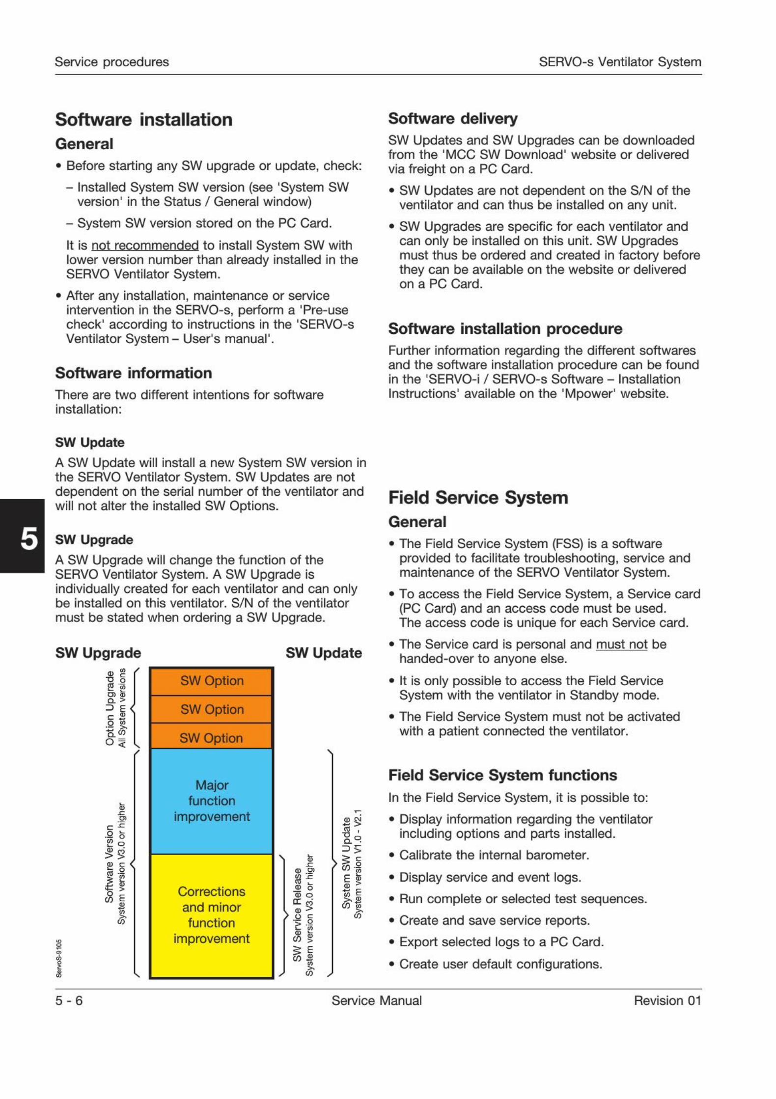
Service procedures SERVO-s Ventilator System
Software installation Software delivery
General
. Before starting any SW upgrade or update, check:
- Installed System SW version (see 'System SWversion' in the Status / General window)
- System SW version stored on the PC Card.
It is not recommended to install System SW withlower version number than already installed in theSERVO Ventilator System.
. After any installation, maintenance or service
intervention in the SERVO-s, perform a 'Pre-usecheck1
according to instructions in the 'SERVO-sVentilator System - User's manual'.
Software information
There are two different intentions for software
installation:
SW Updates and SW Upgrades can be downloadedfrom the 'MCC SW Download' website or delivered
via freight on a PC Card.
. SW Updates are not dependent on the S/N of theventilator and can thus be installed on any unit.
. SW Upgrades are specific for each ventilator andcan only be installed on this unit. SW Upgradesmust thus be ordered and created In factory beforethey can be available on the website or deliveredon a PC Card.
Software installation procedureFurther information regarding the different softwaresand the software installation procedure can be foundIn the 'SERVO-i / SERVO-s Software - Installation
Instructions' available on the 'Mpower' website.
SW Update
A SW Update will install a new System SW version Inthe SERVO Ventilator System. SW Updates are notdependent on the serial number of the ventilator andwill not alter the installed SW Options.
SW Upgrade
A SW Upgrade will change the function of theSERVO Ventilator System. A SW Upgrade isindividually created for each ventilator and can onlybe installed on this ventilator. S/N of the ventilator
must be stated when ordering a SW Upgrade.
Service SystemGeneral
. The Field Service System (FSS) is a softwareprovided to facilitate troubleshooting, service andmaintenance of the SERVO Ventilator System.
. To access the Field Service System, a Service card
(PC Card) and an access code must be used.The access code is unique for each Service card.
SW Upgrade
O) QJCL >
=) £ <c aQ |
/
x:
x:
o
o
<
i E
|ft
n
SW Option
SW Option
SW Option
Majorfunction
improvement
Corrections
and minor
function
improvement
SW Update
\
(D 03
CO0) ca> o
<1> >
s
a;
7)
s
B >%
3
>
g Eft S
%
>
Q-
D
II
. The Service card is personal and must not behanded-over to anyone else.
. It is only possible to access the Field ServiceSystem with the ventilator in Standby mode.
. The Field Service System must not be activatedwith a patient connected the ventilator.
Field Service System functions
In the Field Service System, it is possible to:
. Display information regarding the ventilatorincluding options and parts installed.
. Calibrate the internal barometer.
. Display service and event logs.
. Run complete or selected test sequences.
. Create and save service reports.
. Export selected logs to a PC Card.
. Create user default configurations.
5 - 6 Service Manual Revision 01
SERVO-s Ventilator System Troubleshooting
Only personnel trained and authorizedby MAQUET shall be permitted toperform installation, service ormaintenance of the SERVO-s.
Make sure to prepare the SERVO-s properlybefore disassembling and assembling. Refer tosection 'Hazard notices' in chapter 'Important'.
Any service or maintenance must be noted in alog book.
After any installation, maintenance or serviceintervention in the SERVO-s, perform a 'Pre-usecheck'
. Refer to the 'SERVO-s Ventilator System -User's Manual' for details.
This product contains electronic andelectrical components. Discarddisposable, replaced and left-over partsin accordance with appropriateindustrial and environmental standards.
6. Troubleshooting
General
Pre-use check
Technical error codes
6-2
6-3
6 - 11
Revision 01 Service Manual 6-1

Troubleshooting SERVO-s Ventilator System
Possible causes to malfunction not mentioned in
the following troubleshooting guides are:
. The system has not been correctly assembledafter cleaning, maintenance or service.
. Disconnection or bad connection in cable
connectors, PC board connectors, and inter-
connection boards.
Disconnected or defective gas tubes.
These possible causes to malfunction mustalways be concldered during troubleshooting.
General
Before starting troubleshooting, try to eliminate allpossibilities of operational errors. If the malfunctionremains, use the troubleshooting guides below aswell as the information in chapter
'
Description offunctions' to locate the faulty part. Perform actionsstep by step and check that the malfunction iseliminated.
When the fault is corrected, carry out a complete'Pre-use check' as described in the 'SERVO-s
Ventilator System - User's manual'.
The troubleshooting guides below are focused onlyon technical problems. Information about clinicalrelated problems can be found in the
'SERVO-s
Ventilator System - User's manual'.
For functionality enhancement, the latest releasedSystem SW version is always recommended.
The Information in this chapter applies to Systemversion V3.0 (or higher).
6-2 Service Manual Revision 01
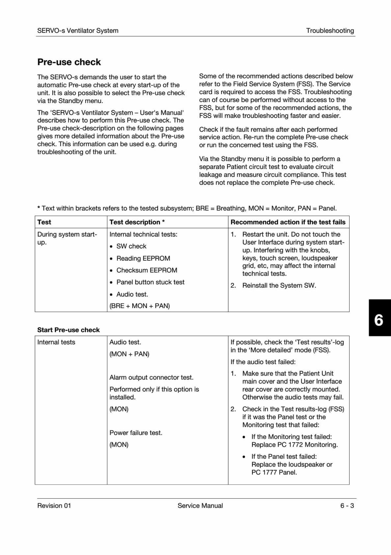
SERVO-s Ventilator System Troubleshooting
Pre-use check
The SERVO-s demands the user to start the
automatic Pre-use check at every start-up of theunit. It is also possible to select the Pre-use checkvia the Standby menu.
The 'SERVO-s Ventilator System - User's Manual'describes how to perform this Pre-use check. ThePre-use check-description on the following pagesgives more detailed information about the Pre-usecheck. This information can be used e.g. duringtroubleshooting of the unit.
Some of the recommended actions described below
refer to the Field Service System (FSS). The Servicecard is required to access the FSS. Troubleshootingcan of course be performed without access to theFSS, but for some of the recommended actions, the
FSS will make troubleshooting faster and easier.
Check if the fault remains after each performedservice action. Re-run the complete Pre-use checkor run the concerned test using the FSS.
Via the Standby menu it is possible to perform aseparate Patient circuit test to evaluate circuitleakage and measure circuit compliance. This testdoes not replace the complete Pre-use check.
* Text within brackets refers to the tested subsystem; BRE = Breathing, MON = Monitor, PAN = Panel.
Test Test description * Recommended action if the test fails
During system start-up.
Internal technical tests:
. SW check
. Reading EEPROM
. Checksum EEPROM
. Panel button stuck test
. Audio test.
(BRE + MON + PAN)
1. Restart the unit. Do not touch the
User Interface during system start-up. Interfering with the knobs,keys, touch screen, loudspeakergrid, etc, may affect the internaltechnical tests.
2. Reinstall the System SW.
Start Pre-use check
Internal tests Audio test.
(MON + PAN)
Alarm output connector test.
Performed only if this option isinstalled.
(MON)
Power failure test.
(MON)
If possible, check the Test results'-login the 'More detailed' mode (FSS).
If the audio test failed:
1. Make sure that the Patient Unit
main cover and the User Interface
rear cover are correctly mounted.Otherwise the audio tests may fail.
2. Check in the Test results-log (FSS)
if it was the Panel test or the
Monitoring test that failed:
. If the Monitoring test failed:Replace PC 1772 Monitoring.
. If the Panel test failed:
Replace the loudspeaker orPC 1777 Panel.
Revision 01 Service Manual 6-3
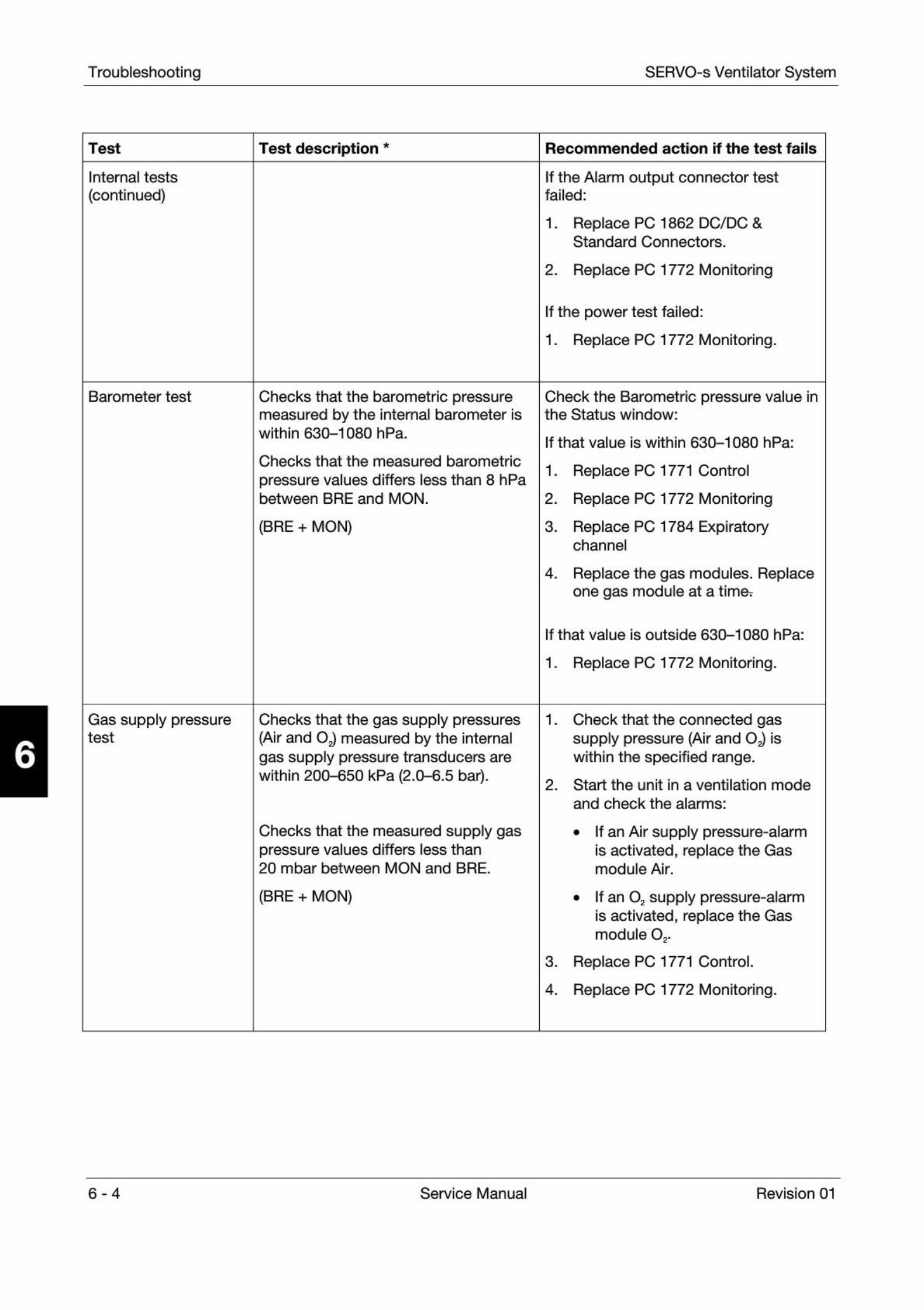
Troubleshooting SERVO-s Ventilator System
Test Test description * Recommended action if the test fails
Internal tests
(continued)If the Alarm output connector testfailed:
1. Replace PC 1862 DC/DC &
Standard Connectors.
2. Replace PC 1772 Monitoring
If the power test failed:
1. Replace PC 1772 Monitoring.
Barometer test Checks that the barometric pressuremeasured by the internal barometer iswithin 630-1080 hPa.
Checks that the measured barometric
pressure values differs less than 8 hPabetween BRE and MON.
(BRE + MON)
Check the Barometric pressure value inthe Status window:
If that value is within 630-1080 hPa:
1. Replace PC 1771 Control
2. Replace PC 1772 Monitoring
3. Replace PC 1784 Expiratory
channel
4. Replace the gas modules. Replace
one gas module at a time:
If that value is outside 630-1080 hPa:
1. Replace PC 1772 Monitoring.
Gas supply pressuretest
Checks that the gas supply pressures(Air and OJ measured by the internalgas supply pressure transducers arewithin 200-650 kPa (2.0-6.5 bar).
Checks that the measured supply gaspressure values differs less than20 mbar between MON and BRE.
(BRE + MON)
1. Check that the connected gas
supply pressure (Air and OJ iswithin the specified range.
2. Start the unit in a ventilation mode
and check the alarms:
. If an Air supply pressure-alarmis activated, replace the Gasmodule Air.
. If an 02 supply pressure-alarmis activated, replace the Gasmodule O..
3.
4.
Replace PC 1771 Control.
Replace PC 1772 Monitoring.
6-4 Service Manual Revision 01
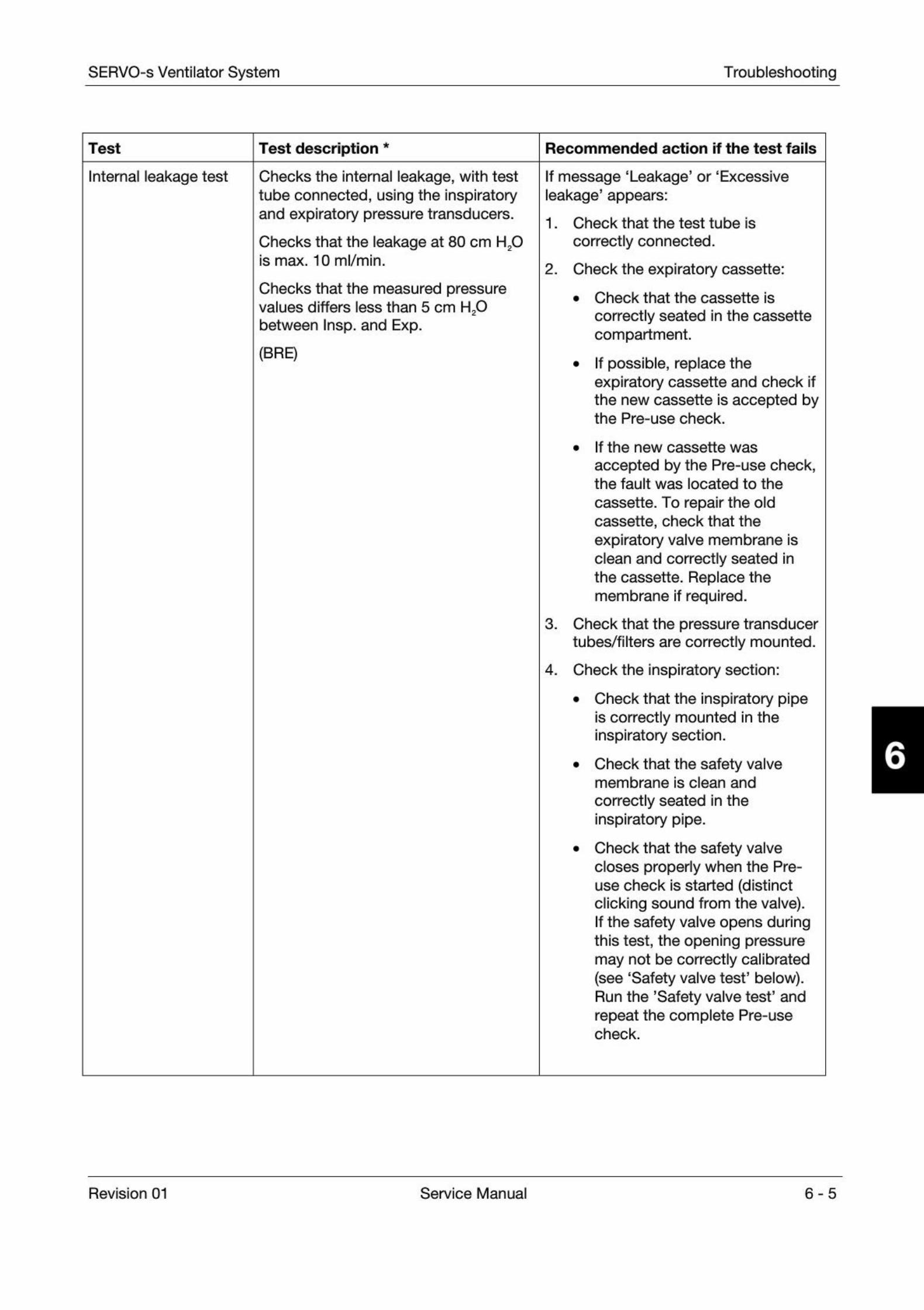
SERVO-s Ventilator System Troubleshooting
Test Test description * Recommended action if the test fails
Internal leakage test Checks the internal leakage, with testtube connected, using the inspiratoryand expiratory pressure transducers.
Checks that the leakage at 80 cm H20is max. 10 ml/min.
Checks that the measured pressurevalues differs less than 5 cm H.O
between Insp. and Exp.
mm
2
If message 'Leakage' or 'Excessiveleakage1 appears:
1. Check that the test tube Is
correctly connected.
2. Check the expiratory cassette:
. Check that the cassette is
correctly seated in the cassettecompartment.
. If possible, replace theexpiratory cassette and check ifthe new cassette is accepted bythe Pre-use check.
. If the new cassette was
accepted by the Pre-use check,the fault was located to the
cassette. To repair the oldcassette, check that the
expiratory valve membrane isclean and correctly seated inthe cassette. Replace themembrane if required.
3. Check that the pressure transducer
tubes/filters are correctly mounted.
4. Check the Inspiratory section:
. Check that the inspiratory pipeis correctly mounted in theinspiratory section.
. Check that the safety valvemembrane is clean and
correctly seated in theinspiratory pipe.
. Check that the safety valvecloses properly when the Pre-use check is started (distinctclicking sound from the valve).If the safety valve opens duringthis test, the opening pressuremay not be correctly calibrated(see 'Safety valve test' below).Run the 'Safety valve test' andrepeat the complete Pre-usecheck.
Revision 01 Service Manual 6-5
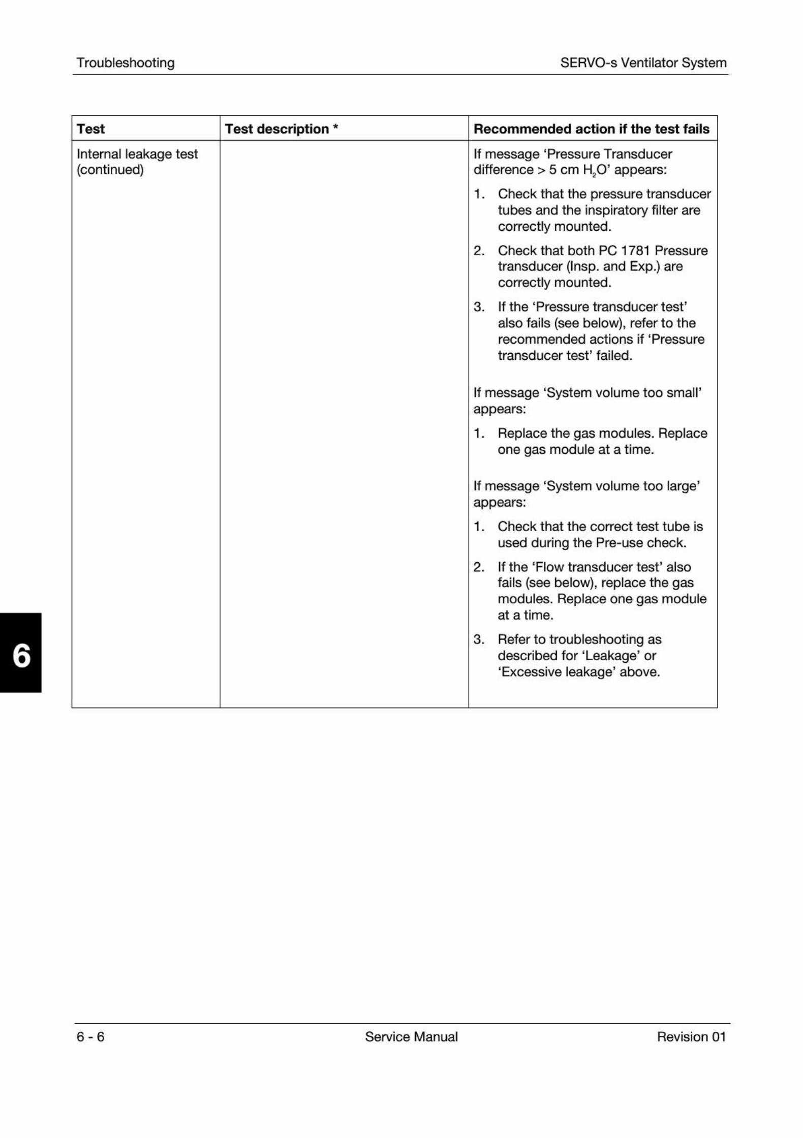
Troubleshooting SERVO-s Ventilator System
Test Test description * Recommended action if the test fails
Internal leakage test(continued)
If message 'Pressure Transducerdifference > 5 cm H20' appears:
1. Check that the pressure transducer
tubes and the inspiratory filter arecorrectly mounted.
2. Check that both PC 1781 Pressure
transducer (Insp. and Exp.) arecorrectly mounted.
3. If the 'Pressure transducer test'
also fails (see below), refer to therecommended actions if 'Pressure
transducer test' failed.
If message 'System volume too small'appears:
1. Replace the gas modules. Replace
one gas module at a time.
If message 'System volume too large'appears:
1. Check that the correct test tube is
used during the Pre-use check.
2. If the 'Flow transducer test' also
fails (see below), replace the gasmodules. Replace one gas moduleat a time.
3. Refer to troubleshooting as
described for 'Leakage' or'Excessive leakage' above.
6-6 Service Manual Revision 01

SERVO-s Ventilator System Troubleshooting
Test Test description * Recommended action if the test fails
Pressure transducer
test
Calibrates and checks the inspiratoryand expiratory pressure transducers.
The new zero value for the pressuretransducers may not differ more than±6 cm H20 from factory calibration.
With the inspiratory pressuretransducers used as a reference, a new
gain factor is set for the expiratorypressure transducer. The new gainfactor may not differ more than ±5%from factory calibration.
During this test, the differentsubsystems concerned are compared.The difference between the
subsystems must not be more than±1 cm H20 at 60 cm H20.
Expiratory valve coil test. Measuresoffset and gain in the valve coil.
(BRE + MON)
Check the Test results'-log in the'More detailed' mode. (FSS)
If 'Pressure transducer test' failed:
1. Check the expiratory cassette:
. If possible, replace theexpiratory cassette and check ifthe new cassette is accepted bythe Pre-use check.
. If the new cassette was
accepted by the Pre-use check,the fault was located to the
cassette.
The fail with the old cassette
may in this case be due to watercollected at the pressuretransducer filter inside the
cassette. Dry the old cassetteproperly.
2. Check/replace PC 1781 Pressure
transducer (Insp. and Exp.).To locate the faulty pressuretransducer, replace one transducerat a time.
3. Replace PC 1771 Control.
4. Replace PC 1772 Monitoring.
If 'Expiration valve test' failed:
1. Check the expiratory cassette:
. If possible, replace theexpiratory cassette and check ifthe new cassette is accepted bythe Pre-use check.
. If the new cassette was
accepted by the Pre-use check,the fault was located to the
cassette. To repair the oldcassette, check that the
expiratory valve membrane isclean and correctly seated inthe cassette. Replace themembrane If required.
2. Replace the Expiratory valve coil.
Revision 01 Service Manual 6-7

Troubleshooting SERVO-s Ventilator System
Test Test description * Recommended action if the test fails
Safety valve test Checks and if necessary adjusts theopening pressure for the safety valve to117 ±3 cm H20.
Checks the hardware signals related tothe safety valve functions.
(BRE + MON)
1. Check the inspiratory section:
. Check that the inspiratory pipeis correctly mounted Ininspiratory section.
. Check that the safety valvemembrane Is clean and
correctly seated in theinspiratory pipe.
2. Replace the safety valve pull
magnet
3. Replace PC 1784 Expiratory
channel.
4. Replace PC 1772 Monitoring.
02 cell/sensor test Calibrates and checks the 02 cell at21% 02 and 100% 02.
Checks if the 02 cell is worn out.
As different gas mixtures are usedduring this test, calibration and checkof 02 cell will not be performed if onegas is missing.
(BRE + MON)
1. Check that the connected gas
supply pressure (Air and iswithin the specified range.
2. Replace the 02 cell.
3. Replace the gas modules. Replace
one gas module at a time.
4. Replace PC 1771 Control.
5. Replace PC 1772 Monitoring.
6-8 Service Manual Revision 01
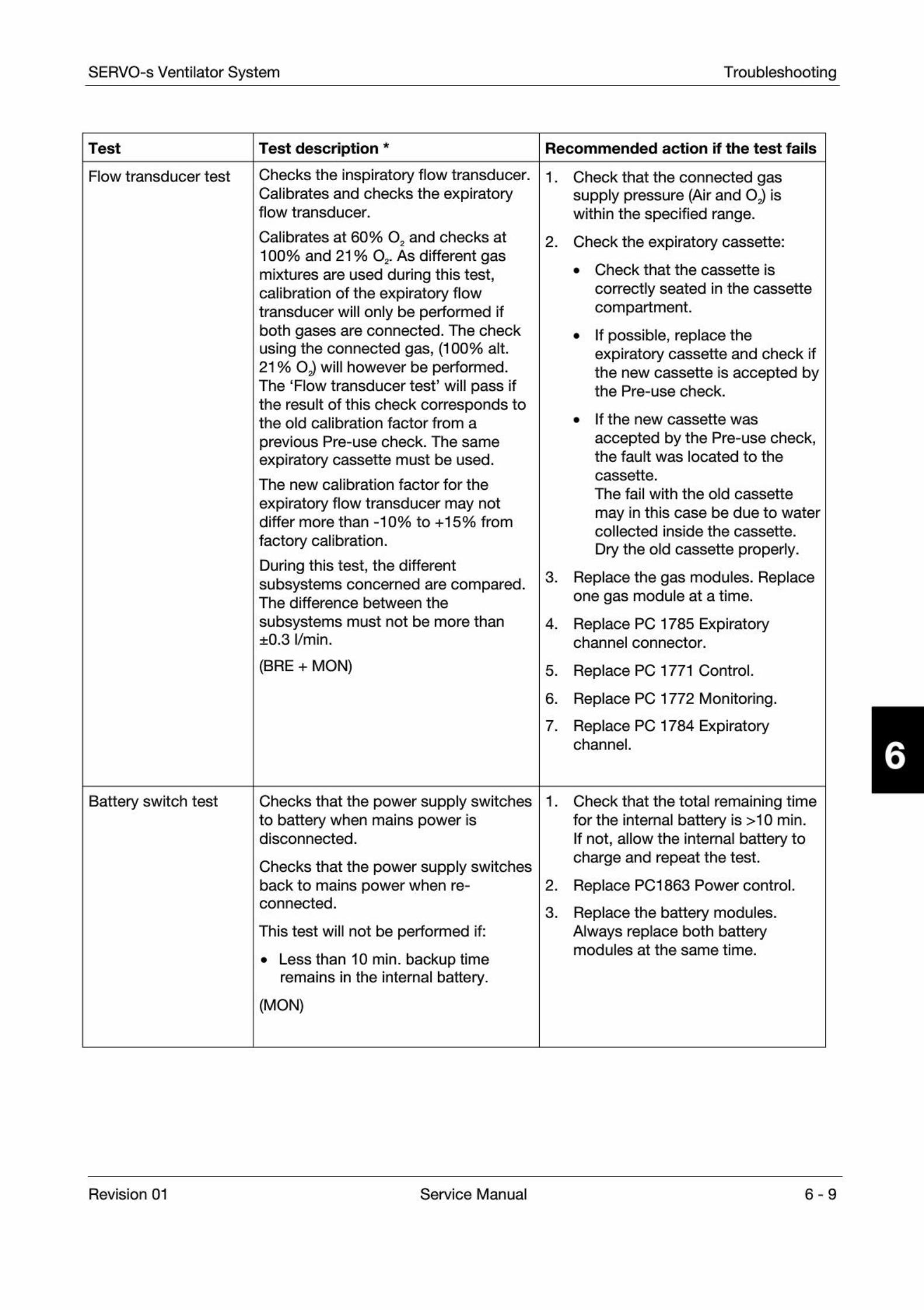
SERVO-s Ventilator System Troubleshooting
Test Test description * Recommended action if the test fails
Flow transducer test Checks the inspiratory flow transducer.Calibrates and checks the expiratoryflow transducer.
Calibrates at 60% 02 and checks at100% and 21 % 02. As different gasmixtures are used during this test,calibration of the expiratory flowtransducer will only be performed ifboth gases are connected. The checkusing the connected gas, (100% alt.21 % Og) will however be performed.The 'Flow transducer test' will pass ifthe result of this check corresponds tothe old calibration factor from a
previous Pre-use check. The sameexpiratory cassette must be used.
The new calibration factor for the
expiratory flow transducer may notdiffer more than -10% to +15% from
factory calibration.
During this test, the differentsubsystems concerned are compared.The difference between the
subsystems must not be more than±0.3 l/min.
(BRE + MON)
1. Check that the connected gas
supply pressure (Air and iswithin the specified range.
2. Check the expiratory cassette:
. Check that the cassette is
correctly seated in the cassettecompartment.
. If possible, replace theexpiratory cassette and check ifthe new cassette is accepted bythe Pre-use check.
. If the new cassette was
accepted by the Pre-use check,the fault was located to the
cassette.
The fail with the old cassette
may in this case be due to watercollected inside the cassette.
Dry the old cassette properly.
3. Replace the gas modules. Replace
one gas module at a time.
4. Replace PC 1785 Expiratory
channel connector.
5. Replace PC 1771 Control.
6. Replace PC 1772 Monitoring.
7. Replace PC 1784 Expiratory
channel.
Battery switch test Checks that the power supply switchesto battery when mains power isdisconnected.
Checks that the power supply switchesback to mains power when re-connected.
This test will not be performed if:
. Less than 10 min. backup time
remains in the internal battery.
(MON)
1. Check that the total remaining time
for the internal battery is >10 min.If not, allow the internal battery tocharge and repeat the test.
2. Replace PCI 863 Power control.
3. Replace the battery modules.
Always replace both batterymodules at the same time.
Revision 01 Service Manual 6-9
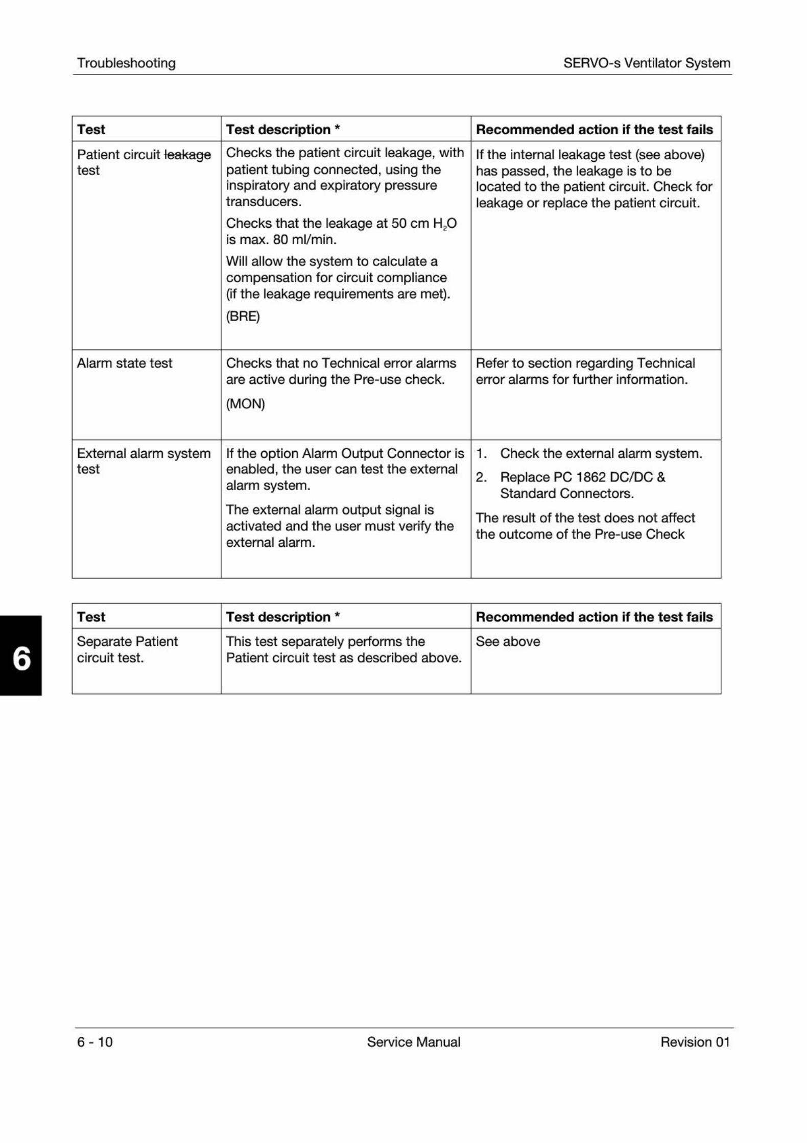
Troubleshooting SERVO-s Ventilator System
Test Test description * Recommended action if the test fails
Patient circuit
test
Checks the patient circuit leakage, withpatient tubing connected, using theinspiratory and expiratory pressuretransducers.
Checks that the leakage at 50 cm H20is max. 80 ml/min.
Will allow the system to calculate acompensation for circuit compliance(if the leakage requirements are met).
(BRE)
If the internal leakage test (see above)has passed, the leakage is to belocated to the patient circuit. Check forleakage or replace the patient circuit.
Alarm state test Checks that no Technical error alarms
are active during the Pre-use check.
(MOM)
Refer to section regarding Technicalerror alarms for further information.
External alarm systemtest
If the option Alarm Output Connector isenabled, the user can test the external
alarm system.
The external alarm output signal isactivated and the user must verify theexternal alarm.
1. Check the external alarm system.
2. Replace PC 1862 DC/DC &
Standard Connectors.
The result of the test does not affect
the outcome of the Pre-use Check
Test Test description * Recommended action if the test fails
Separate Patientcircuit test.
This test separately performs thePatient circuit test as described above.
See above
6-10 Service Manual Revision 01
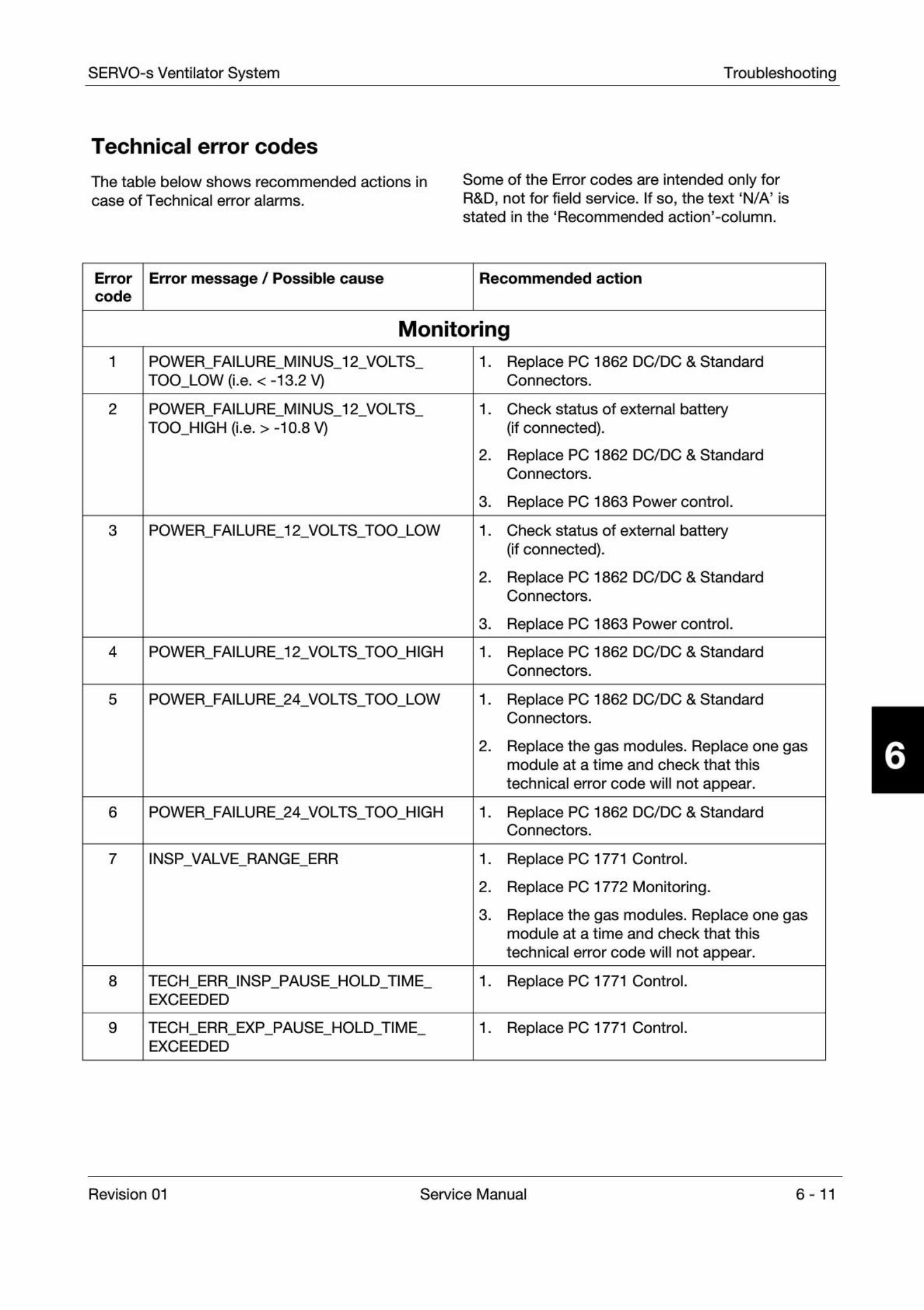
SERVO-s Ventilator System Troubleshooting
Technical error codes
The table below shows recommended actions in Some of the Error codes are intended only forcase of Technical error alarms. R&D, not for field service. If so, the text 'N/A' is
stated in the 'Recommended action'-column.
Error
codeError message / Possible cause Recommended action
Monitoringi POWER
_
FAILURE_
MINUS_
12_
VOLTS
TOO_
LOW (i.e. <-13.2 V)1
. Replace PC 1862 DC/DC & StandardConnectors.
2 POWER_
FAILURE_
MINUS_
12_
VOLTS
TOO_
HIGH (i.e. >-10.8 V)1
. Check status of external battery(if connected).
2. Replace PC 1862 DC/DC & Standard
Connectors.
3. Replace PC 1863 Power control.
3 POWER FAILURE 12 VOLTS TOO LOW 1. Check status of external battery
(if connected).
2. Replace PC 1862 DC/DC & Standard
Connectors.
3. Replace PC 1863 Power control.
4 POWER FAILURE 12 VOLTS TOO HIGH 1. Replace PC 1862 DC/DC & Standard
Connectors.
5 POWER FAILURE 24 VOLTS TOO LOW 1. Replace PC 1862 DC/DC & Standard
Connectors.
2. Replace the gas modules. Replace one gas
module at a time and check that this
technical error code will not appear.
6 POWER FAILURE 24 VOLTS TOO HIGH 1. Replace PC 1862 DC/DC & Standard
Connectors.
7 INSP VALVE RANGE ERR 1. Replace PC 1771 Control.
2. Replace PC 1772 Monitoring.
3. Replace the gas modules. Replace one gas
module at a time and check that this
technical error code will not appear.
8 TECH_
ERRJNSP_
PAUSE_
HOLD_
TIME
EXCEEDED
1. Replace PC 1771 Control.
9 TECH_
ERR_
EXP_
PAUSE_
HOLD_
TIME
EXCEEDED
1. Replace PC 1771 Control.
Revision 01 Service Manual 6 -11
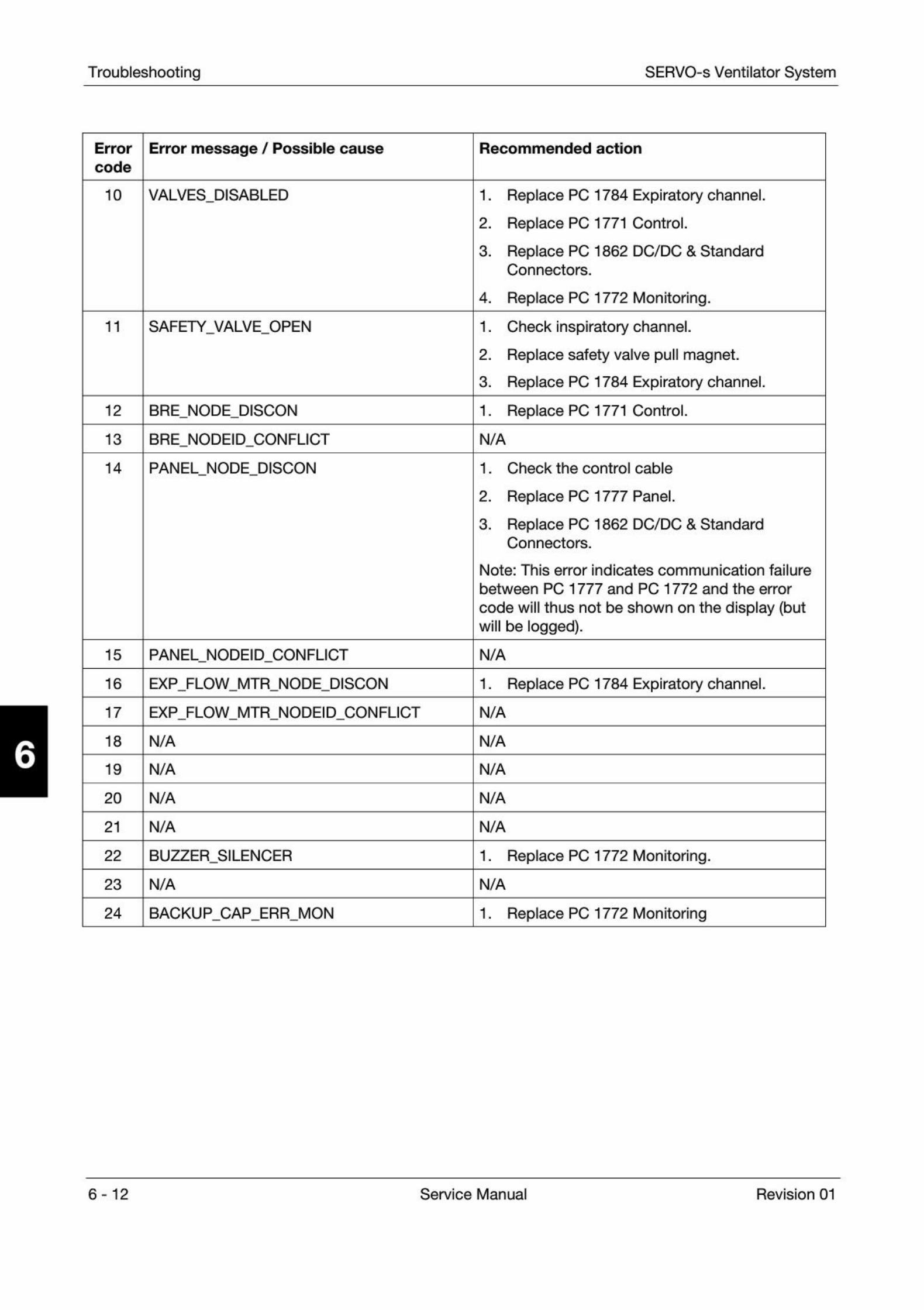
Troubleshooting SERVO-s Ventilator System
Error
codeError message / Possible cause Recommended action
10 VALVES DISABLED 1. Replace PC 1784 Expiratory channel.
2. Replace PC 1771 Control.
3. Replace PC 1862 DC/DC & Standard
Connectors.
4. Replace PC 1772 Monitoring.
11 SAFETY VALVE OPEN 1. Check inspiratory channel.
2. Replace safety valve pull magnet.
3. Replace PC 1784 Expiratory channel.
12 BRE NODE DISCON 1. Replace PC 1771 Control.
13 BRE NODEID CONFLICT N/A
14 PANEL NODE DISCON 1. Check the control cable
2. Replace PC 1777 Panel.
3. Replace PC 1862 DC/DC & Standard
Connectors.
Note: This error indicates communication failure
between PC 1777 and PC 1772 and the error
code will thus not be shown on the display (butwill be logged).
15 PANEL NODEID CONFLICT N/A
16 EXP FLOW MTR NODE DISCON 1. Replace PC 1784 Expiratory channel.
17 EXP FLOW MTR NODEID CONFLICT N/A
18 N/A N/A
19 N/A N/A
20 N/A N/A
21 N/A N/A
22 BUZZER SILENCER 1. Replace PC 1772 Monitoring.
23 N/A N/A
24 BACKUP CAP ERR MON 1. Replace PC 1772 Monitoring
6- 12 Service Manual Revision 01
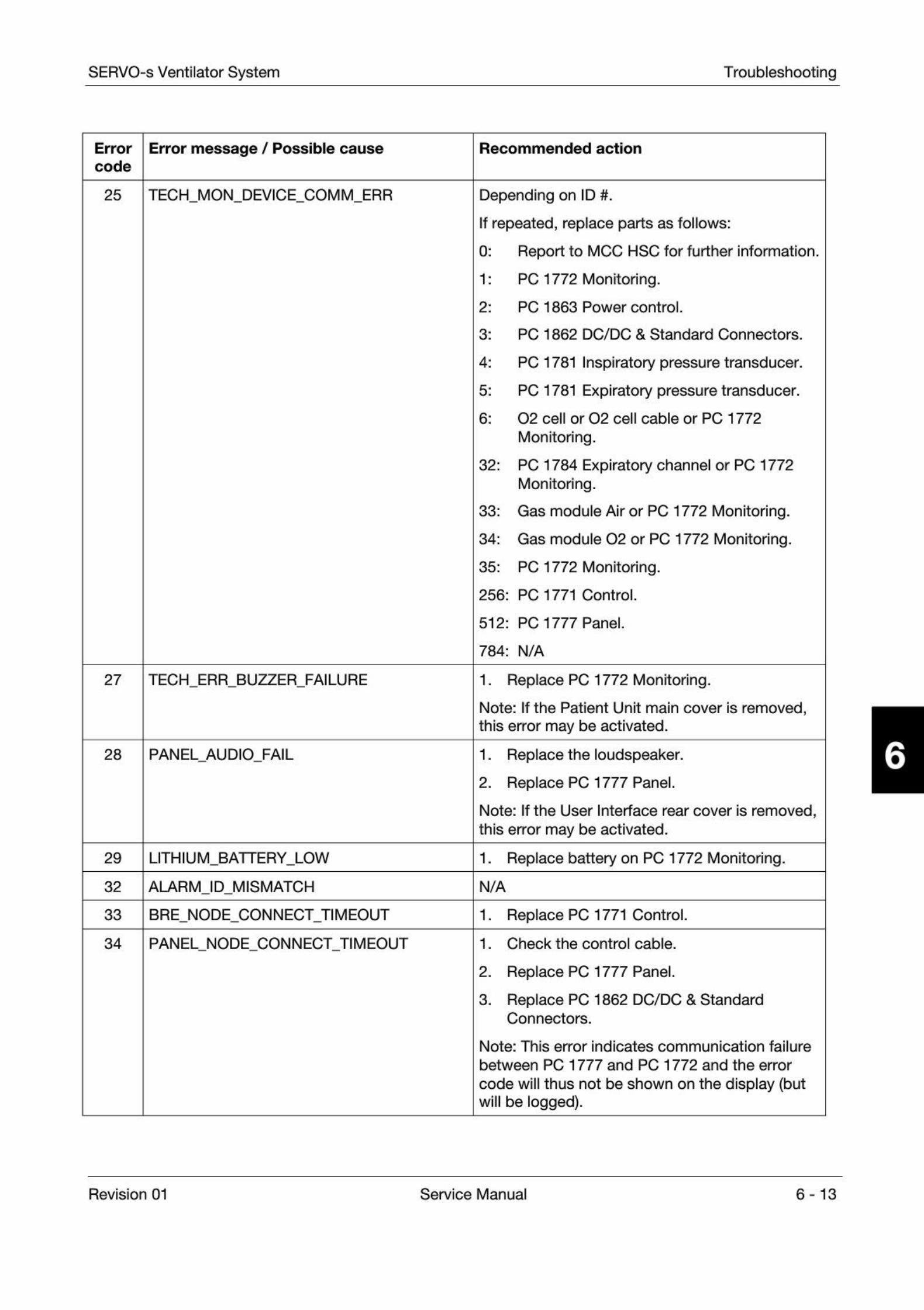
SERVO-s Ventilator System Troubleshooting
Error Error message / Possible causecode
Recommended action
25 TECH MON DEVICE COMM ERR Depending on ID #.
If repeated, replace parts as follows:
0
1
2
3
Report to MCC HSC for further information.
PC 1772 Monitoring.
PC 1863 Power control.
PC 1862 DC/DC & Standard Connectors.
4: PC 1781 Inspiratory pressure transducer.
5: PC 1781 Expiratory pressure transducer.
6: 02 cell or 02 cell cable or PC 1772
Monitoring.
32: PC 1784 Expiratory channel or PC 1772Monitoring.
33: Gas module Air or PC 1772 Monitoring.
34: Gas module 02 or PC 1772 Monitoring.
35: PC 1772 Monitoring.
256: PC 1771 Control.
512
784
PC 1777 Panel.
N/A
27 TECH ERR BUZZER FAILURE 1. Replace PC 1772 Monitoring.
Note: If the Patient Unit main cover is removed,
this error may be activated.
28 PANEL AUDIO FAIL 1. Replace the loudspeaker.
2. Replace PC 1777 Panel.
Note: If the User Interface rear cover is removed,
this error may be activated.
29 LITHIUM BATTERY LOW 1. Replace battery on PC 1772 Monitoring.
32 ALARM ID MISMATCH N/A
33 BRE NODE CONNECT TIMEOUT 1. Replace PC 1771 Control.
34 PANEL NODE CONNECT TIMEOUT 1. Check the control cable.
2. Replace PC 1777 Panel.
3. Replace PC 1862 DC/DC & Standard
Connectors.
Note: This error indicates communication failure
between PC 1777 and PC 1772 and the error
code will thus not be shown on the display (butwill be logged).
Revision 01 Service Manual 6-13
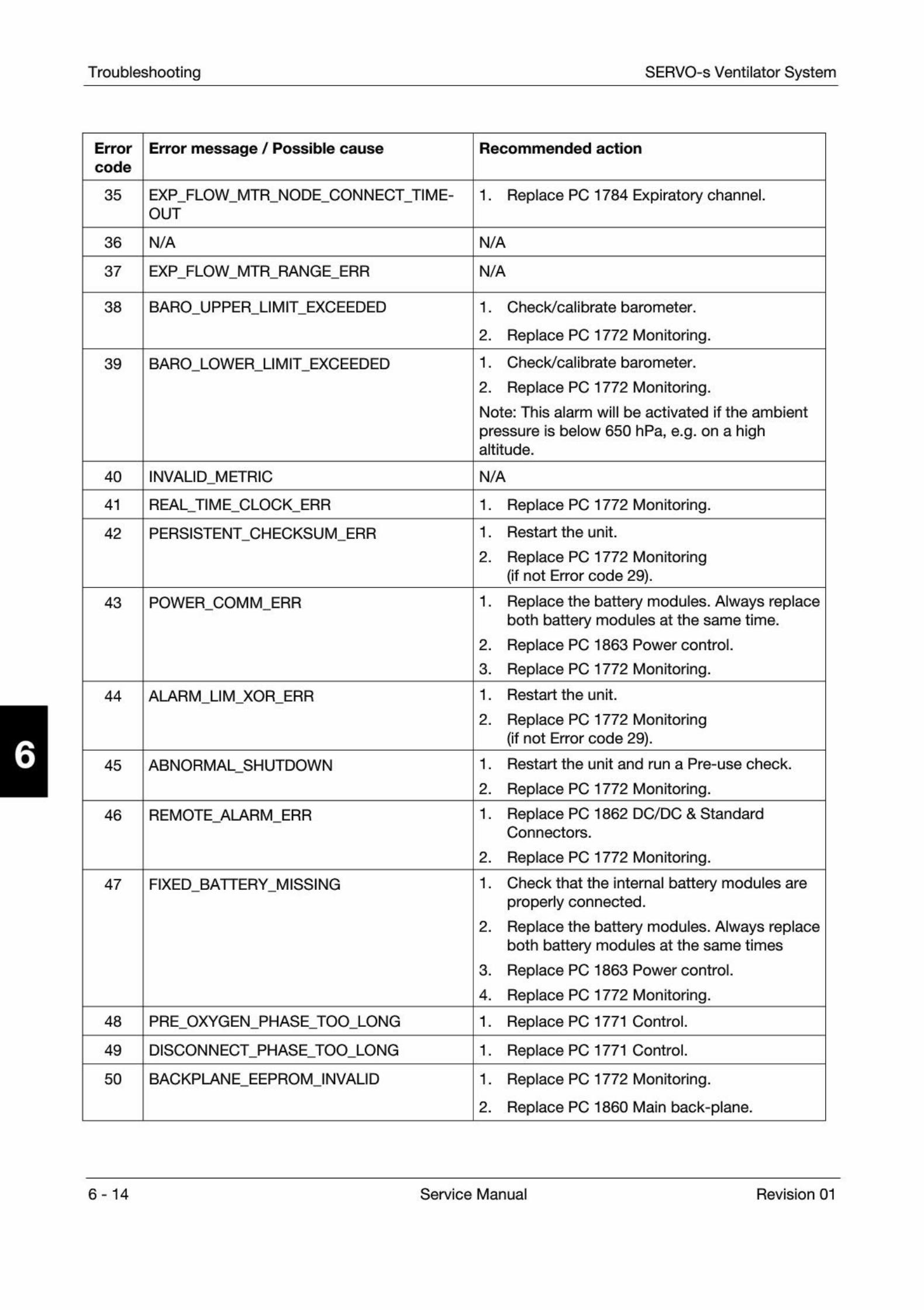
Troubleshooting SERVO-s Ventilator System
Error
codeError message / Possible cause Recommended action
35 EXP_
FLOW_
MTR_
NODE_
CONN ECTTIM E-
OUT
1. Replace PC 1784 Expiratory channel.
36 N/A N/A
37 EXP FLOW MTR RANGE ERR N/A
38 BARO UPPER LIMIT EXCEEDED 1. Check/calibrate barometer.
2. Replace PC 1772 Monitoring.
39 BARO LOWER LIMIT EXCEEDED 1. Check/calibrate barometer.
2. Replace PC 1772 Monitoring.
Note: This alarm will be activated if the ambient
pressure is below 650 hPa, e.g. on a highaltitude.
40 INVALID METRIC N/A
41 REAL TIME CLOCK ERR 1. Replace PC 1772 Monitoring.
42 PERSISTENT CHECKSUM ERR 1. Restart the unit.
2. Replace PC 1772 Monitoring
(If not Error code 29).
43 POWER COMM ERR 1. Replace the battery modules. Always replace
both battery modules at the same time.
2. Replace PC 1863 Power control.
3. Replace PC 1772 Monitoring.
44 ALARM LIM XOR ERR 1. Restart the unit.
2. Replace PC 1772 Monitoring
(if not Error code 29).
45 ABNORMAL SHUTDOWN 1. Restart the unit and run a Pre-use check.
2. Replace PC 1772 Monitoring.
46 REMOTE ALARM ERR 1. Replace PC 1862 DC/DC & Standard
Connectors.
2. Replace PC 1772 Monitoring.
47 FIXED BATTERY MISSING 1. Check that the internal battery modules are
properly connected.
2. Replace the battery modules. Always replace
both battery modules at the same times
3. Replace PC 1863 Power control.
4. Replace PC 1772 Monitoring.
48 PRE OXYGEN PHASE TOO LONG 1. Replace PC 1771 Control.
49 DISCONNECT PHASE TOO LONG 1. Replace PC 1771 Control.
50 BACKPLANE EEPROM INVALID 1. Replace PC 1772 Monitoring.
2. Replace PC 1860 Main back-plane.
6- 14 Service Manual Revision 01
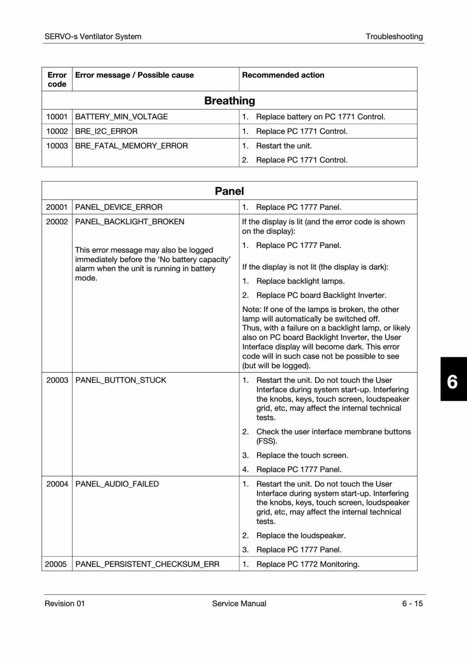
SERVO-s Ventilator System Troubleshooting
Error | Error message / Possible causecode
Recommended action
Breathing10001 BATTERY MIN VOLTAGE 1
. Replace battery on PC 1771 Control.
10002 BRE I2C ERROR 1. Replace PC 1771 Control.
10003 BRE FATAL MEMORY ERROR 1. Restart the unit.
2. Replace PC 1771 Control.
Panel
20001 PANEL DEVICE ERROR 1. Replace PC 1777 Panel.
20002 PANEL BACKLIGHT BROKEN
This error message may also be loggedimmediately before the 'No battery capacity'alarm when the unit is running in batterymode.
If the display is lit (and the error code is shownon the display):
1. Replace PC 1777 Panel.
If the display is not lit (the display is dark):
1. Replace backlight lamps.
2. Replace PC board Backlight Inverter.
Note: If one of the lamps is broken, the otherlamp will automatically be switched off.Thus, with a failure on a backlight lamp, or likelyalso on PC board Backlight Inverter, the UserInterface display will become dark. This errorcode will in such case not be possible to see(but will be logged).
20003 PANEL BUTTON STUCK 1. Restart the unit. Do not touch the User
Interface during system start-up. Interferingthe knobs, keys, touch screen, loudspeakergrid, etc, may affect the internal technicaltests.
2. Check the user interface membrane buttons
(FSS).
3. Replace the touch screen.
4. Replace PC 1777 Panel.
20004 PANEL AUDIO FAILED 1. Restart the unit. Do not touch the User
Interface during system start-up. Interferingthe knobs, keys, touch screen, loudspeakergrid, etc, may affect the internal technicaltests.
2. Replace the loudspeaker.
3. Replace PC 1777 Panel.
20005 I PANEL PERSISTENT CHECKSUM ERR 1. Replace PC 1772 Monitoring.
Revision 01 Service Manual 6-15
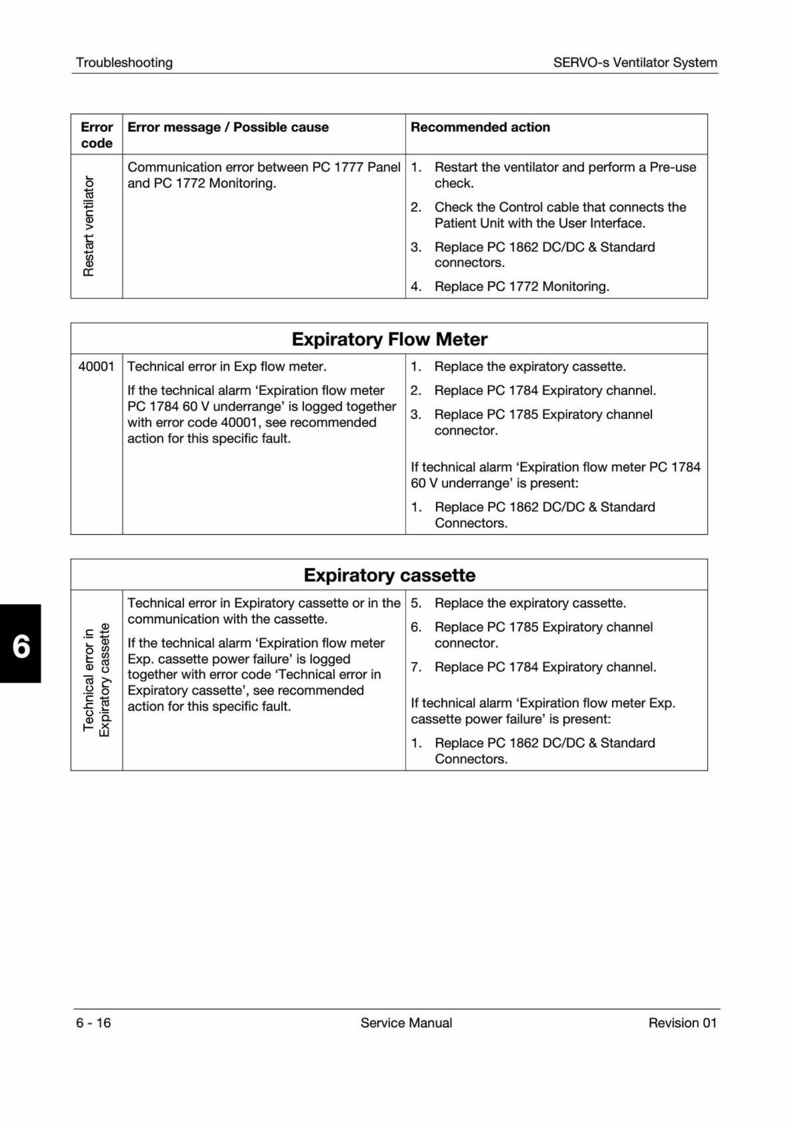
Troubleshooting SERVO-s Ventilator System
Error
codeError message / Possible cause Recommended action
o
>
%
Communication error between PC 1777 Panel
and PC 1772 Monitoring.
1. Restart the ventilator and perform a Pre-use
check.
2. Check the Control cable that connects the
Patient Unit with the User Interface.
3. Replace PC 1862 DC/DC & Standard
connectors.
4. Replace PC 1772 Monitoring.
Expiratory Flow Meter
40001 Technical error in Exp flow meter.
If the technical alarm 'Expiration flow meterPC 1784 60 V underrange' is logged togetherwith error code 40001, see recommended
action for this specific fault.
1. Replace the expiratory cassette.
2. Replace PC 1784 Expiratory channel.
3. Replace PC 1785 Expiratory channel
connector.
If technical alarm 'Expiration flow meter PC 178460 V underrange' is present:
1. Replace PC 1862 DC/DC & Standard
Connectors.
Expiratory cassette
«s
.52 o
8-
a
Technical error in Expiratory cassette or in thecommunication with the cassette.
If the technical alarm 'Expiration flow meterExp. cassette power failure' is loggedtogether with error code Technical error inExpiratory cassette', see recommendedaction for this specific fault.
5. Replace the expiratory cassette.
6. Replace PC 1785 Expiratory channel
connector.
7. Replace PC 1784 Expiratory channel.
If technical alarm 'Expiration flow meter Exp.cassette power failure
'
is present:
1. Replace PC 1862 DC/DC & Standard
Connectors.
6-16 Service Manual Revision 01
SERVO-s Ventilator System Preventive maintenance
Only personnel trained and authorizedby MAQUET shall be permitted toperform installation, service ormaintenance of the SERVO-s.
Make sure to prepare the SERVO-s properlybefore disassembling and assembling. Refer tosection 'Hazard notices' in chapter 'Important'.
Any service or maintenance must be noted in alog book.
After any installation, maintenance or serviceIntervention in the SERVO-s, perform a 'Pre-usecheck'
. Refer to the 'SERVO-s Ventilator System -User's Manual' for details.
This product contains electronic andelectrical components. Discarddisposable, replaced and left-over partsin accordance with appropriateindustrial and environmental standards.
7. Preventive maintenance
General
Preparations
Equipment..
Preventive maintenance
Maintenance kit, 5,000 hours
Performing the Preventive maintenance
7-2
7-2
7-2
7-3
7-3
7-3
7
Revision 01 Service Manual 7 -1
Preventive maintenance SERVO-s Ventilator System
7
General
. A 'Preventive maintenance1 must be performed atleast once every year as long as the unit is not usedmore than normal. Normal operation is estimatedto correspond to approx. 5,000 hours of operation.
. The life span for the Battery module is calculatedto two and a half year from manufacturing date.Normal time for logistics and storage are includedin this calculation. The calculation correspondsthus to an estimated operational time of two years.Manufacturing date (year-week) is printed on thebattery label.
. The internal Lithium batteries on PC 1771 and
PC 1772 shall be replaced every five years.
. After or in combination with performing the'
Preventive maintenance' described in this chapter,a 'Routine cleaning' and an 'Extended cleaning ofInspiratory channel' must be performed.For cleaning procedures, refer to the 'SERVO-sVentilator System - User's manual'.
. In some parts of the Preventive maintenance, as
described in this chapter, access to the FieldService System (FSS) is required.
. Some optional equipment used with the SERVO-s,
but not covered by this Service Manual, may alsodemand maintenance actions. Refer to the optionalequipments documentation. Example on suchoptional equipment are:- Humidifier
- Compressor Mini.
Preparations. Make sure that the SERVO-s works properly before
performing any maintenance.
. Set the On/Off switch on the User Interface to Off.
. Disconnect the mains power cable.
. Disconnect the gas supplies (wall and/or cylinder).
. Remove patient tubing.
. If fitted, remove bacteria filter from the expiratory
inlet.
Equipment. Standard service tools
.
. Barometer (or information about the actualbarometric pressure).
. Access to the Field Service System (FSS).
Recommended but not required.
. Preventive maintenance kit containing all partsneeded during the maintenance.
7-2 Service Manual Revision 01
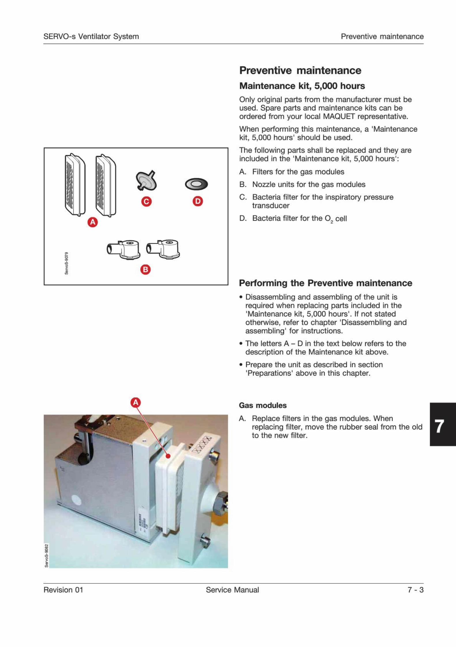
SERVO-s Ventilator System Preventive maintenance
0
5
Preventive maintenance
Maintenance kit, 5,000 hours
Only original parts from the manufacturer must beused. Spare parts and maintenance kits can beordered from your local MAQUET representative.
When performing this maintenance, a 'Maintenancekit, 5,000 hours' should be used.
The following parts shall be replaced and they areincluded in the 'Maintenance kit, 5,000 hours':
A. Filters for the gas modules
B. Nozzle units for the gas modules
C. Bacteria filter for the inspiratory pressure
transducer
D. Bacteria filter for the O cell
Performing the Preventive maintenance
. Disassembling and assembling of the unit isrequired when replacing parts included in the'Maintenance kit, 5,000 hours'. If not statedotherwise, refer to chapter
'
Disassembling andassembling
' for instructions.
. The letters A - D in the text below refers to the
description of the Maintenance kit above.
. Prepare the unit as described in section'Preparations' above in this chapter.
: V
1
-
8
Gas modules
A. Replace filters in the gas modules. When
replacing filter, move the rubber seal from the old
to the new filter.7
Revision 01 Service Manual 7-3
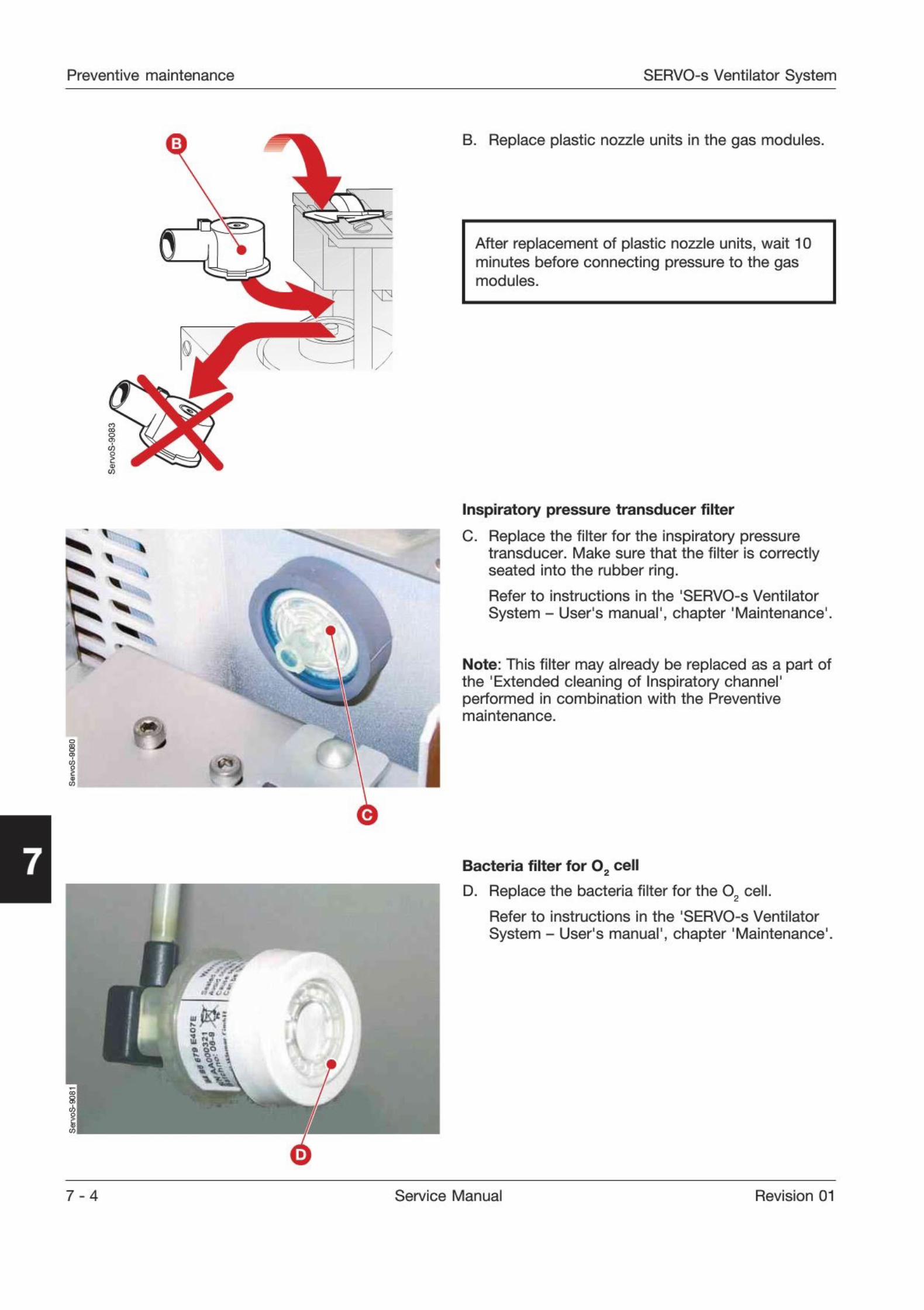
Preventive maintenance SERVO-s Ventilator System
B. Replace plastic nozzle units in the gas modules.
After replacement of plastic nozzle units, wait 10minutes before connecting pressure to the gasmodules.
7
Inspiratory pressure transducer filter
C. Replace the filter for the inspiratory pressure
transducer. Make sure that the filter is correctlyseated into the rubber ring.
Refer to instructions in the 'SERVO-s Ventilator
System - User's manual', chapter 'Maintenance'.
Note: This filter may already be replaced as a part ofthe 'Extended cleaning of Inspiratory channel'performed in combination with the Preventivemaintenance.
i
I r
mE3
Bacteria filter for 02 cell
D. Replace the bacteria filter for the 0
2 cell.
Refer to instructions in the 'SERVO-s Ventilator
System - User's manual', chapter 'Maintenance'.
7 - 4 Service Manual Revision 01
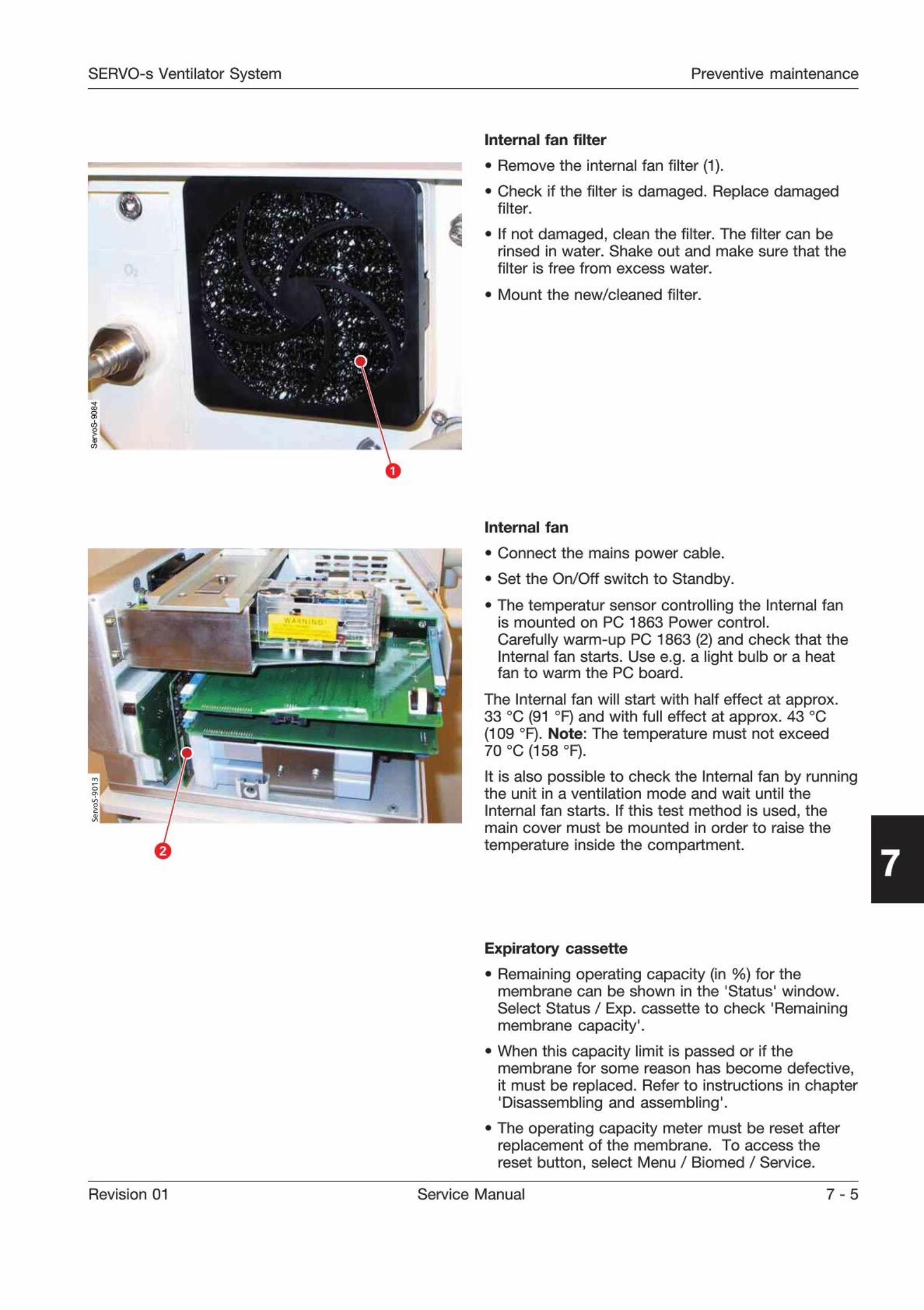
SERVO-s Ventilator System Preventive maintenance
1
Internal fan filter
. Remove the internal fan filter (1).
. Check if the filter is damaged. Replace damagedfilter.
. If not damaged, clean the filter. The filter can be
rinsed in water. Shake out and make sure that the
filter is free from excess water.
. Mount the new/cleaned filter.
' r
I"
-
-
>
Internal fan
. Connect the mains power cable.
. Set the On/Off switch to Standby.
. The temperatur sensor controlling the Internal fanis mounted on PC 1863 Power control.
Carefully warm-up PC 1863 (2) and check that theInternal fan starts. Use e.g. a light bulb or a heatfan to warm the PC board.
The Internal fan will start with half effect at approx.33 0C (91 0F) and with full effect at approx. 43 0C(109 0F). Note: The temperature must not exceed70 0C (158 0F).
It is also possible to check the Internal fan by runningthe unit in a ventilation mode and wait until the
Internal fan starts. If this test method is used, the
main cover must be mounted in order to raise the
temperature inside the compartment.7
Expiratory cassette
. Remaining operating capacity (in %) for themembrane can be shown in the 'Status' window.
Select Status / Exp. cassette to check 'Remainingmembrane capacity
'
.
. When this capacity limit is passed or if themembrane for some reason has become defective,it must be replaced. Refer to instructions in chapter'
Disassembling and assembling'.
. The operating capacity meter must be reset afterreplacement of the membrane. To access thereset button, select Menu / Biomed / Service.
Revision 01 Service Manual 7 - 5
Preventive maintenance SERVO-s Ventilator System
7
User Interface
. Check the touch screen readability:
- Transparency- Surface
- Brightness (backlight). Estimated lifetime (withacceptable brightness level) for the lamps is30,000 hours. Using the Field Service System(FSS), a time meter for the lamps can be shown.The time meter must be reset after replacementof the lamps.
. Check if pixels on the touch screen are defective.
Open the Status window. A few defective pixelscan be accepted. Check that defective pixels arenot concentrated to a small area thus reducing thereadability in this area.FSS is recommended but not required.
. Perform the checks listed below and make sure
that the software responds to these actions. FSS isrecommended but not required.
- Check the touch screen functions. Press buttons
on different parts of the touch screen.
- Check the Main Rotary Dial. Turn and press theMain Rotary Dial.
- Check the Direct Access Knobs. Turn all Direct
Access Knobs.
- Check the membrane buttons. Press all
membrane buttons.
Barometric pressure
. Select Status / General on the User Interface.
Check that the Barometric pressure value shownon the User Interface corresponds to the actualBarometric pressure value at the local site. Thevalue shown on the User Interface may not differmore than ±5% from the actual barometric
pressure.
. If the value shown on the User Interface differs
more than ±5% from the actual barometric
pressure, the barometer in SERVO-s must becalibrated. FSS is required.
Battery modules
System SW version V2.01.00 (or higher) includes anadvanced monitoring of the battery status. TheSystem SW will, among others, monitor:
. Expiry date. The life span for the Battery module iscalculated to two and a half year frommanufacturing date.
. If the operational capacity is too poor for continuedusage.
In both cases, battery replacement information willbe shown on the User Interface.
Select 'Status / Batteries' on the User Interface to
check battery status. For further information, refer tochapter
'
Service procedures', section 'Batterymodules'
.
Note: Replace both batteries at the same time.
Lithium batteries
. Check manufacturing date for the lithium batteriesmounted onto PC 1771 and PC 1772. The batteries
must be replaced after 5 years. Replacement isdescribed in chapter 'Service procedures'.
Safety inspection
. Make a visual inspection of the SERVO-s forexternal defects or damages. Replace defective ordamaged parts.
. Check the mains power cable and control cableand their connections for damage.
. Perform a leakage current test. The leakage currenttest is a standard procedure regulated by IEC 60601-1 or corresponding national standards.Allowable values and test methods are defined in
the standard. The use of a leakage tester, e. g.Bender Safety Tester 601/751 or equivalent isrecommended.
. Check that a 'SERVO-s Ventilator System - User'smanual' corresponding to the installed Systemversion is present. Also check that operatingmanuals for all optional equipment connected tothe Servo-s are present.
Gas supply pressure transducers
. Connect the gas supplies (Air and 02).
. Select Status / General on the User Interface.
. Disconnect the gas supply, one gas at the time.
. Check that the corresponding supply pressurevalue in the 'Status'-window drops.
Completing the Preventive maintenance
. Perform a 'Pre-use check'. Refer to the'
SERVO-s Ventilator System - User's manual'.
. Perform 'Function checks' on the optionalequipments connected to the SERVO-s. Refer tothe operating manuals for these optionalequipments.
. Reset the Preventive maintenance time meter.
Use the reset button (select Menu / Biomed /Service / Report PM) or use the FSS. Also note in aSERVO-s log book that a Preventive maintenancehas been performed.
7 - 6 Service Manual Revision 01
SERVO-s Ventilator System Index
Only personnel trained and authorizedby MAQUET shall be permitted toperform installation, service ormaintenance of the SERVO-s.
Make sure to prepare the SERVO-s properlybefore disassembling and assembling. Refer tosection 'Hazard notices' in chapter 'Important'.
Any service or maintenance must be noted in alog book.
After any installation, maintenance or serviceintervention in the SERVO-s, perform a 'Pre-usecheck'
. Refer to the 'SERVO-s Ventilator System -User's Manual' for details.
This product contains electronic andelectrical components. Discarddisposable, replaced and left-over partsin accordance with appropriateindustrial and environmental standards.
8. Index
Alphabetic index 8-2
Revision 01 Service Manual 8-1
Index SERVO-s Ventilator System
A
AC/DC Converter 2-7. 3-9, 4-14Aeroneb Pro 2-3
Alarm output connector 2-3, 2-6, 9-2Assembling guidelines 4-2
B
Backlight Inverter 3-3, 4-6Backlight lamps 2-5, 4-9Bacteria filter for 02 cell 7-4
Barometric pressure 7-6Battery modules 2-7, 3-10, 4-14, 5-2, 7-6Biomed key 5-4Breathing 2-9
CCable reel 2-4
Change access code 5-5Compressor Mini 2-3Connector muff 2-7, 3-4
Control cable 2-4, 3-10, 4-20Control cable connector 2-6
Copy configuration 5-5
D
Direct access controls 2-4, 2-5
Display with touch screen 2-4Edit configuration 5-5
E
Edit configuration 5-5Environmental declaration 1 -6
Equipotentiality terminal 2-6ESD protection 4-2Expiratory cassette 2-8, 3-6, 6-16, 7-5Expiratory cassette membrane 4-19Expiratory inlet 2-6Expiratory outlet 2-6Expiratory section 3-6Expiratory valve coil 2-8, 4-18External +12 V DC supply 2-6, 9-2
F
Field service system (FSS) 5-6Fixed keys 2-4Functional check 1-5
Functional main blocks diagram 9-3Fuse FI 2-6
, 3-9
Fuse F11 2-6, 3-9
Fuse F12 2-6, 3-9
G
Gas cylinder restrainer 2-3Gas modules 2-6, 3-3, 4-13, 7-3Gas supply pressure transducers 7-6
H
Handling PC boards 4-2Hazard notices 1-4
Humidifier holder 2-3
Inspiratory channel 4-16Inspiratory outlet 2-6, 3-5Inspiratory pipe 2-7, 3-4Inspiratory pressure transducer filter 7-4Inspiratory pressure transducer tube 2-7, 3-5Inspiratory section 3-3Installation 1-5
Internal fan 2-6, 2-7, 3-10, 4-16, 7-5Internal fan filter 7-5
L
Label strips 4-10Lithium batteries 5-3, 7-6
Locking arm 2-4Loudspeaker 2-5, 3-2Loudspeaker grid 2-4Luminescence detector 2-4
M
Main blocks diagram 9-3Main cover 4-12
Main rotary dial 2-4, 2-5Main units 2-2
Mains indicator 2-4
Mains Inlet 3-9
Mains supply connector 2-6Maintenance kit 5,000 hours 7-3
Memory types 3-2Menu key 5-4Mobile cart 2-3
Monitoring 2-9
N
N26 9-2
N28 9-2
N29 9-2
N70 9-2
8-2 Service Manual Revision 01
SERVO-s Ventilator System Index
O
02 cell 2-7, 3-5
02 cell adaption 5-5On/Off switch 2-4
Optional connectors 9-2Optional equipment 2-3
P
P63 9-2
Panel 2-9
Patient Unit 2-2, 2-6, 3-3, 4-12, 4-13PC 1771 Control 2-7, 3-8, 4-2, 4-14, 5-3PC 1772 Monitoring 2-7, 3-8, 4-2, 4-14, 5-3PC 1777 Panel 2-5, 3-2, 4-2, 4-3,
4-4
PC 1781 Expiratory pressure transducer 2-8, 3-7PC 1781 Inspiratory pressure transducer 2-8, 3-7PC 1784 Expiratory channel 2-8, 3-8, 4-2, 4-17PC 1785 Expiratory channel connector 2-8, 3-7,
4-18
PC 1860 Main back-plane 2-7, 3-7, 4-15PC 1861 Pneumatic back-plane 2-7, 3-5. 4-17PC 1862 DC/DC & Standard connectors 2-7
, 3-9, 4-15PC 1863 Power control 2-7
, 3-10, 4-15PC board Backlight inverter 2-5PC card slot 2-4
Power supply 3-9Pressure transducers 3-7
Pre-use check 6-3
Preventive maintenance 7-3
Preventive maintenance kit 7-3
Standard connectors 9-2
Standby indicator 2-4Start/Stop (Standby) ventilation key 2-4Support Arm 177 2-3Support plate 4-3SW Update 5-6SW Upgrade 5-6Symbols used In this manual 1-4System ID 2-9, 4-15System SW 3-2, 4-2, 5-6
T
Technical error codes 6-11
Temperature sensor 3-9, 3-10TFT Display 2-5, 3-3,
4-7
Threadlocking adhesives 4-2Tightening torque 4-2Touch screen incl. frame 2-5
, 3-3, 4-3, 4-10
u
User Interface 2-2, 2-4, 3-2, 4-3, 7-6User Interface controls 3-2
User interface panel cover 2-3
W
Waterbag pole 2-3
R
Rear cover 4-3
Replacing PC boards 4-2RS232 2-6
, 9-2
s
Safety inspection 7-6Safety valve 2-7, 3-5Safety valve membrane 4-16Serial number 1-4
Serial number label 2-4, 2-6
Serial port 2-6Service 1-5, 5-4
Service card 5-6
Service connector 2-4
Set date and clock 5-5
Shelf base 2-3
Side cover 4-12
Software information 5-6
Software installation 5-6
Software installation procedure 5-6Software structure 2-9
Special function keys 2-4
Revision 01 Service Manual 8-3
Index SERVO-s Ventilator System
Notes
8 - 4 Service Manual Revision 01
SERVO-s Ventilator System Diagrams
Only personnel trained and authorizedby MAQUET shall be permitted toperform installation, service ormaintenance of the SERVO-s.
Make sure to prepare the SERVO-s properlybefore disassembling and assembling. Refer tosection 'Hazard notices' in chapter 'Important'.
Any service or maintenance must be noted in alog book.
After any installation, maintenance or serviceintervention in the SERVO-s, perform a 'Pre-usecheck'
. Refer to the 'SERVO-s Ventilator System -User's Manual' for details.
This product contains electronic andelectrical components. Discarddisposable, replaced and left-over partsin accordance with appropriateindustrial and environmental standards.
9. Diagrams
Standard and optional connectors
Functional Main Blocks diagram ..
9-2
9-3
Revision 01 Service Manual 9 -1
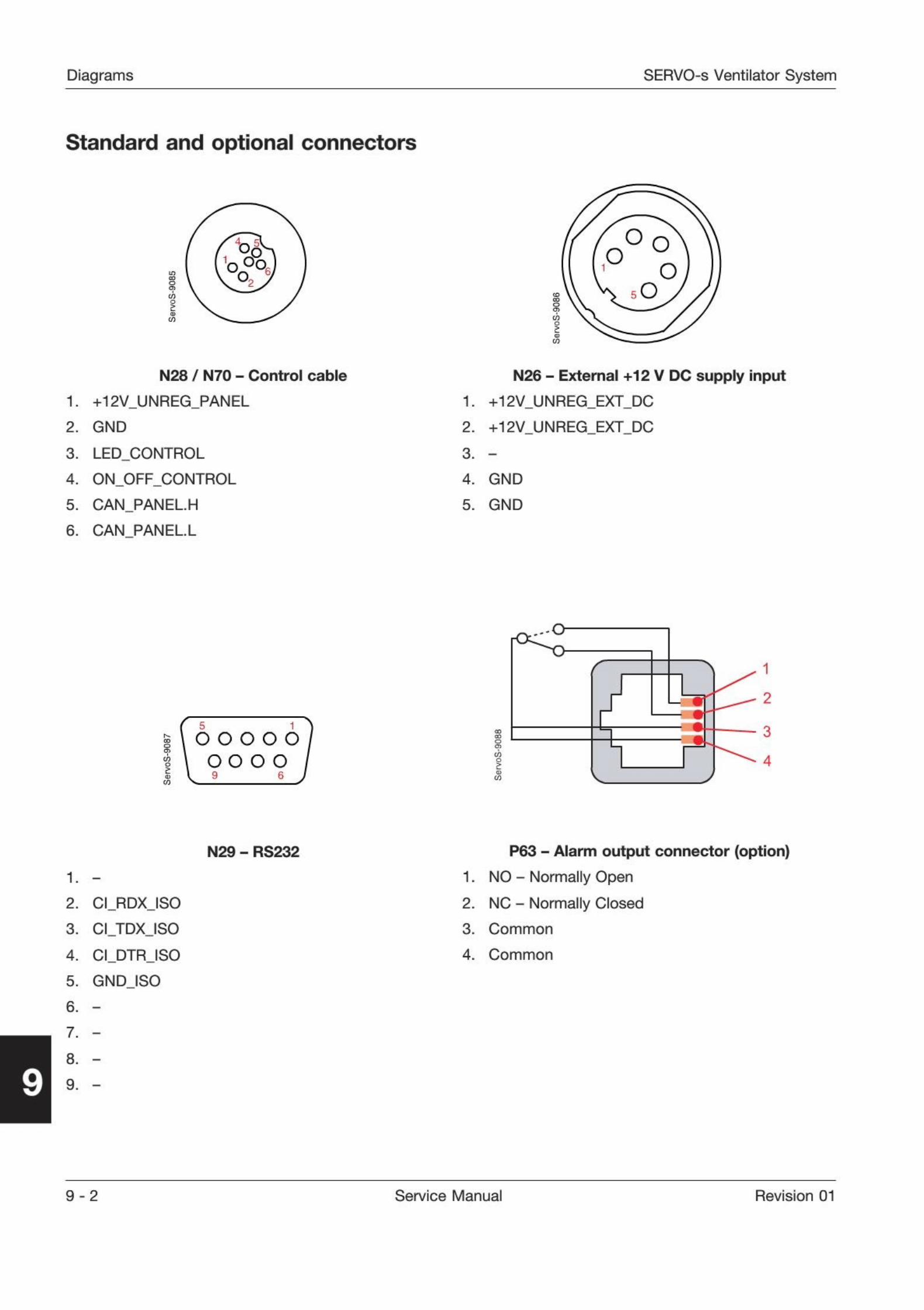
Diagrams SERVO-s Ventilator System
Standard and optional connectors
egi
ooOn
o
O OO
OO
N28 / N70 - Control cable
1. +12V
_
UNREG_
PANEL
2. GND
3. LED
.
CONTROL
4. ON
_
OFF_
CONTROL
5. CAN
_
PANELH
6. CAN PANELL
N26 - External +12 V DC supply input
1. +12V_
UNREG_
EXT_
DC
2. +12V
_
UNREG_
EXT_
DC
3. -
4. GND
5. GND
i \ 6 o o o 6/I \ oo o o /CO
CD
O
iCO
2
3
4
N29 - RS232
1. -
2. GLRDXJSO
3. CLTDXJSO
4. CLDTRJSO
5. GNDJSO
6. -
7. -
8. -
9. -
P63 - Alarm output connector (option)
1. NO - Normally Open
2. NC - Normally Closed
3. Common
4. Common
9-2 Service Manual Revision 01
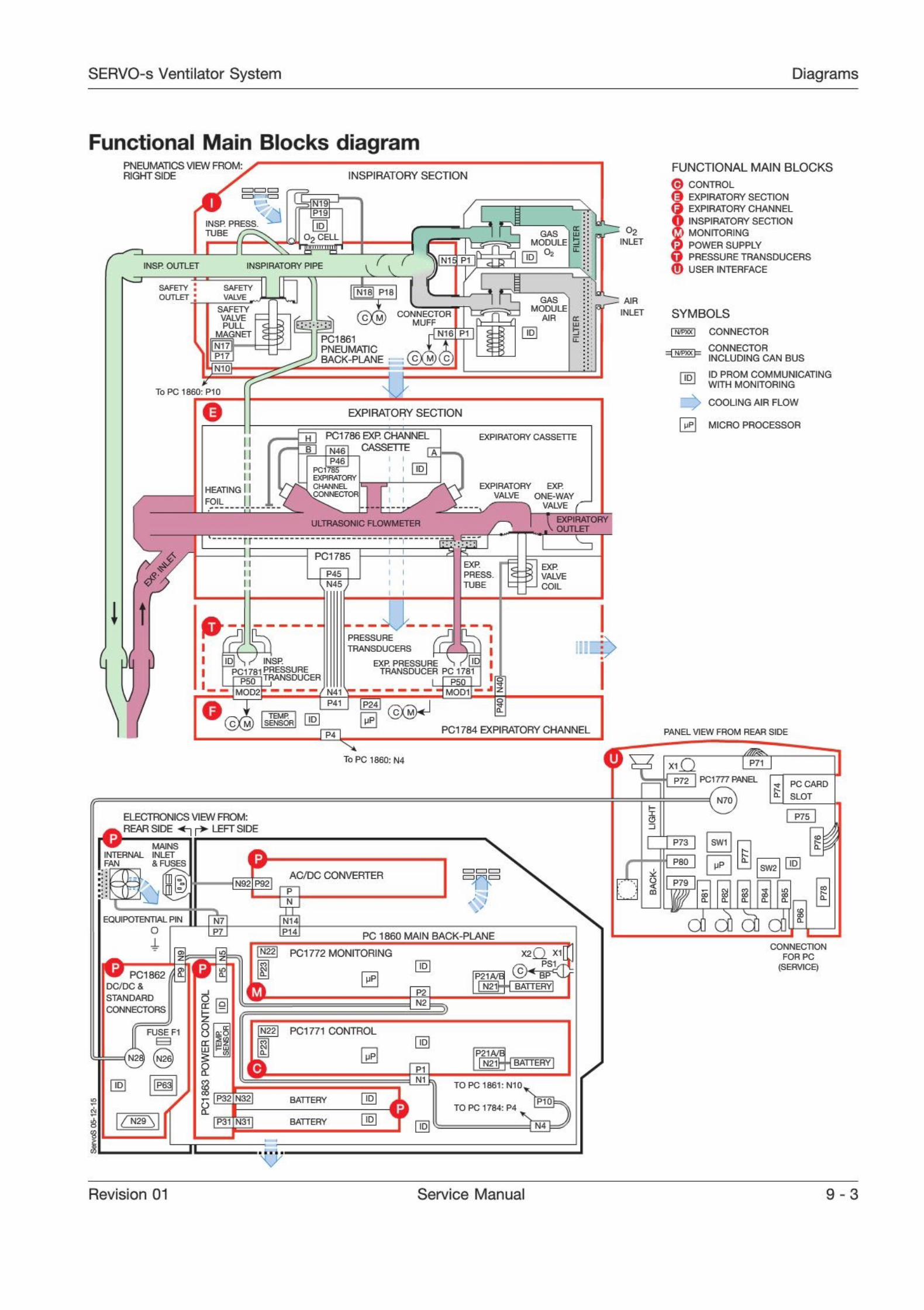
SERVO-s Ventilator System Diagrams
Functional Main Blocks diagramPNEUMATICS VIEW FROM:RIGHT SIDE
FUNCTIONAL MAIN BLOCKS
CONTROL
EXPIRATORY SECTION
EXPIRATORY CHANNEL
INSPIRATORY SECTION
MONITORING
POWER SUPPLY
PRESSURE TRANSDUCERS
0 USER INTERFACE
SYMBOLS
mw\ CONNECTOR
CONNECTORINCLUDING CAN BUS
rini ID PROM COMMUNICATING1-' WITH MONITORING
N COOLING AIR FLOW
[mp] micro processor
NSP RATORY SECT ON
N19
PI 9
INSP PRESS.
TUBE O2NLET
GASMODULE
Oi CELL
m 0NSR OUTLET NSP RATORY P PE
SAFETY .OUTLET
SAFETY
tfALVEP18
GASMODULE
AIR
AIR
INLETSAFETYVALVEPULL
MAGNET
t i a
IDPCI 861PNEUMATICBACK-PLANE
Ml 7=1P 7
EXP RATORY SECT ON
H] PCI786EXR CHANNELr
~I imzi CASSETTE fEXP RATORY CASSETTE
N46
i P46PC 1 5EXPIRATORYCHANNELCONNECTOR
D
/W\ CHAN NIC/ \ ONNE(
EXPIRATORY EXP
VALVE ONE-WAY
VALVE (
HEATING
FO L
EXPIRATORY
OUTLETJLTRASONIC FLOWMETER
'
A PCI 785EXP
PRESS.TUBE
EXP.5 VALVE- COIL
P45
N4.5
i j-
.
PRESSURE
TRANSDUCERS
INSR
PCI 781 PRESSUREEXP. PRESSURE 1 f U
TRANSDUCER PC 1781TRANSDUCER
HP50I
z
nMOD2 ' 1 MOD
0.1 P41 POi
a.
0TEMPSENSOR D
PCI 784 EXPIRATORY CHANNEL PANEL V EW FROM REAR S D£J4
To PC 1860: N4 P7
=72 PCI .77 PANEL
( N7Q)
3C CARD
SLOT
-
ELECTRONICS VIEW FROM:
REAR SIDE - r LEFTSIDEP75C3
| SW11W MAINSINTERNAL INLETFAN & FUSES 9 P80
SW2
Is AC/DC CONVERTERP7992 P92
"
1~
2a.
i d cA,EQUIPOTENTIALPIN | [nTIo I LezI
a.
PC 1860 MAIN BACK-PLANE
IN22] pci772 MONITORING X20 XI3> 43Z Z
cW PCI 862DC/DC &
STANDARD
CONNECTORS
a. BPP21A/HPN21H-I BATTERY|
P2
Ed N2
i3 Nt22J PCI 771 CONTROL
P 0FUSE F1
X
P21A/BN2
BATTERY
pea TO PC 1861: N10
TO PC 1784: P4M32 BATTERY
1
m/ N29\ P3 N3 BATTERY
n
CONNECTION
FOR PC
(SERVICE)
Revision 01 Service Manual 9-3
MAQUETMaquet Critical Care ABSE-171 95 Solna, Sweden
Phone: +46 8 730 73 00
www.maquet.com/criticalcare
For local contact:
Please visit our website
www.maquet.com
I
8
i
ii
iii5
GETINGE
GET1NGE GROUP is a leading global provider of equipment and
systems that contribute to quality enhancement and cost efficiencywithin healthcare and life sciences. Equipment, services and tech-
nologies are supplied under the brands ARJO for patient hygiene,patient handling and wound care. GETINGE for infection controland prevention within healthcare and life science and MAQUET forSurgical Workplaces, Cardiopulmonary and Critical Care.