Embed Size (px)
Citation preview
Session 3: The Systems Engineering “V”
Welcome and Introductions
Process Overview
Systems Engineering “V”
Cross-Cutting Activities
Applying SE to a Project
Establishing SE in your Organization
Process Improvement Discussion
Wrap Up
These materials developed under the RITA National ITS Architecture Program
3-2
Learning Outcome
Explain the Systems Engineering “V” Process
3-3
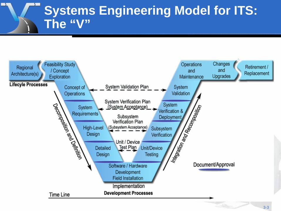
Systems Engineering Model for ITS: The “V”
3-4
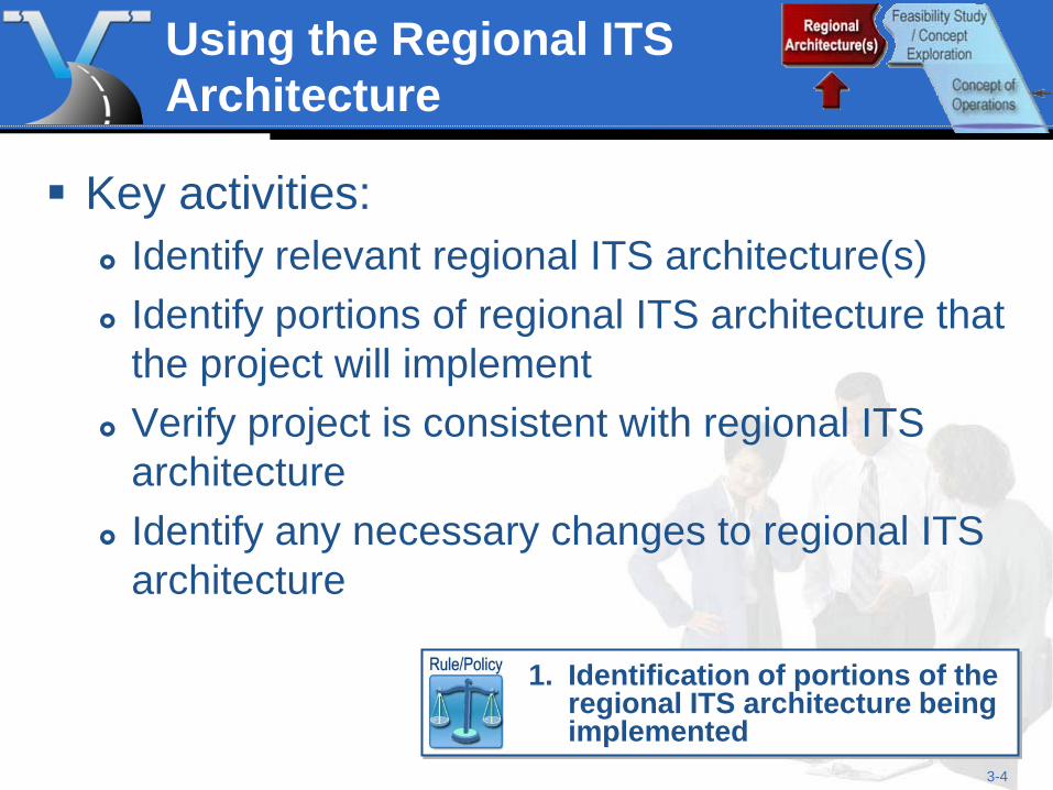
Using the Regional ITS Architecture
Key activities: Identify relevant regional ITS architecture(s) Identify portions of regional ITS architecture that
the project will implement Verify project is consistent with regional ITS
architecture Identify any necessary changes to regional ITS
architecture
1. Identification of portions of the
regional ITS architecture being implemented
3-5
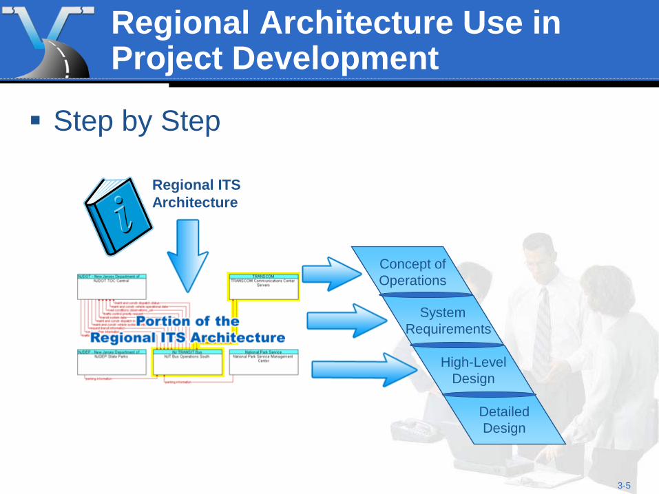
Concept of Operations
System Requirements
High-Level Design
Regional Architecture Use in Project Development
Step by Step
Regional ITS Architecture
Detailed Design
3-6
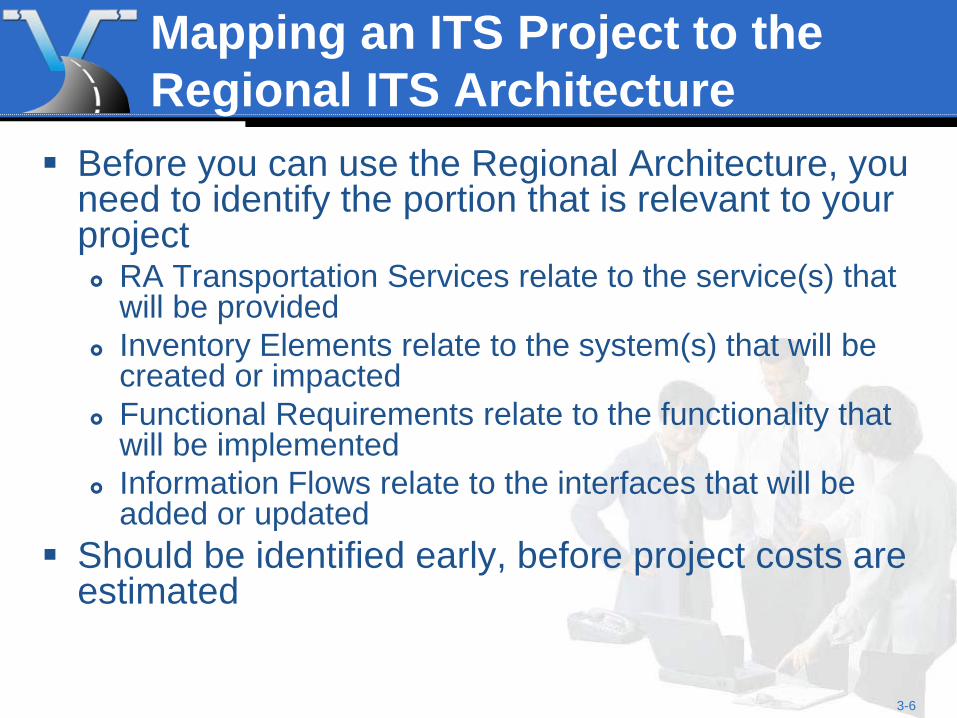
Mapping an ITS Project to the Regional ITS Architecture
Before you can use the Regional Architecture, you need to identify the portion that is relevant to your project RA Transportation Services relate to the service(s) that
will be provided Inventory Elements relate to the system(s) that will be
created or impacted Functional Requirements relate to the functionality that
will be implemented Information Flows relate to the interfaces that will be
added or updated Should be identified early, before project costs are
estimated
3-7
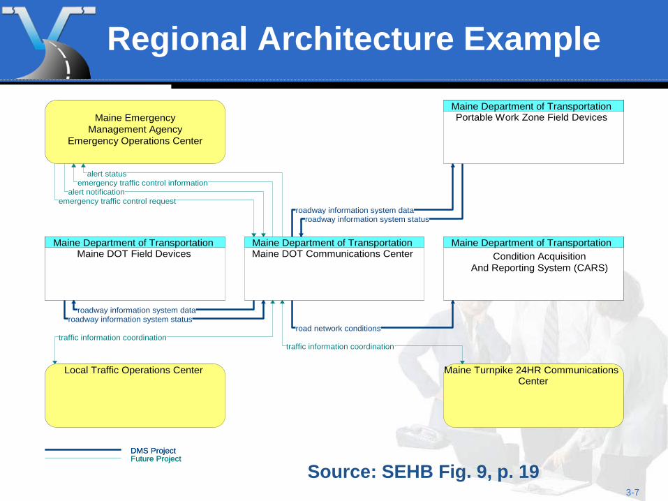
Regional Architecture Example
Maine Department of TransportationMaine DOT Communications Center
Maine EmergencyManagement Agency
Emergency Operations Center
Maine Department of TransportationPortable Work Zone Field Devices
Maine Department of TransportationMaine DOT Field Devices
Maine Department of TransportationCondition Acquisition
And Reporting System (CARS)
Local Traffic Operations Center Maine Turnpike 24HR CommunicationsCenter
alert statusemergency traffic control information
alert notificationemergency traffic control request
roadway information system dataroadway information system status
roadway information system dataroadway information system status
road network conditionstraffic information coordination
traffic information coordination
DMS ProjectFuture Project
Source: SEHB Fig. 9, p. 19
3-8
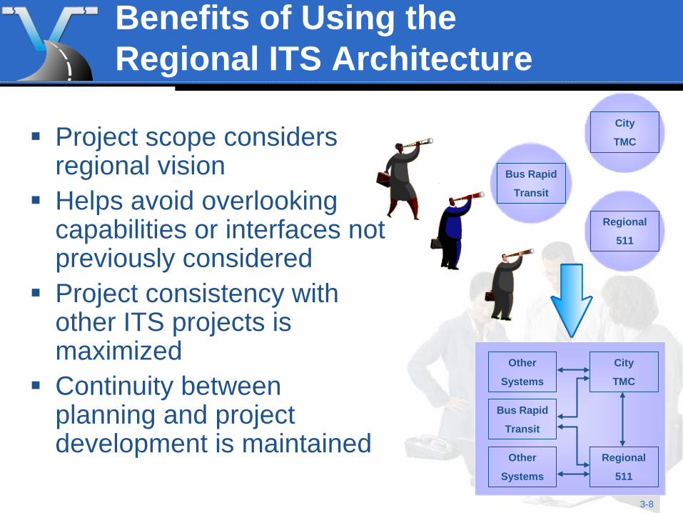
Benefits of Using the Regional ITS Architecture
City
TMC
Regional
511
Bus Rapid
Transit
City
TMC
Regional
511
Bus Rapid
Transit
Other
Systems
Other
Systems
Project scope considers regional vision
Helps avoid overlooking capabilities or interfaces not previously considered
Project consistency with other ITS projects is maximized
Continuity between planning and project development is maintained
3-9
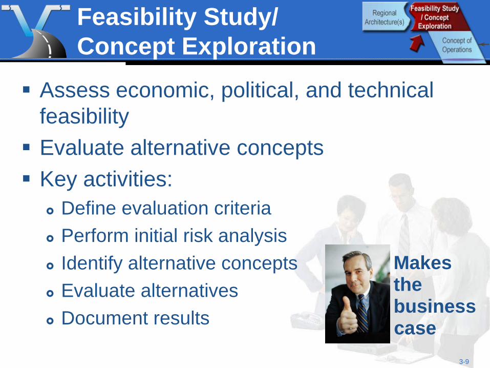
Feasibility Study/ Concept Exploration
Assess economic, political, and technical feasibility Evaluate alternative concepts Key activities:
Define evaluation criteria Perform initial risk analysis Identify alternative concepts Evaluate alternatives Document results
Makes the business case
3-10
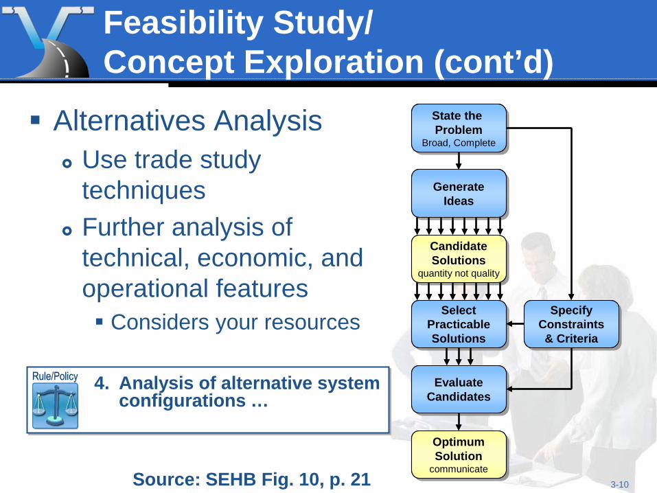
Feasibility Study/ Concept Exploration (cont’d)
Alternatives Analysis Use trade study
techniques Further analysis of
technical, economic, and operational features Considers your resources
State the Problem
Broad, Complete
State the Problem
Broad, Complete
GenerateIdeas
GenerateIdeas
CandidateSolutions
quantity not quality
CandidateSolutions
quantity not quality
SpecifyConstraints& Criteria
SpecifyConstraints& Criteria
SelectPracticableSolutions
SelectPracticableSolutions
EvaluateCandidatesEvaluate
Candidates
OptimumSolution
communicate
OptimumSolution
communicate
State the Problem
Broad, Complete
State the Problem
Broad, Complete
GenerateIdeas
GenerateIdeas
CandidateSolutions
quantity not quality
CandidateSolutions
quantity not quality
SpecifyConstraints& Criteria
SpecifyConstraints& Criteria
SelectPracticableSolutions
SelectPracticableSolutions
EvaluateCandidatesEvaluate
Candidates
OptimumSolution
communicate
OptimumSolution
communicateSource: SEHB Fig. 10, p. 21
4. Analysis of alternative system
configurations …
3-11
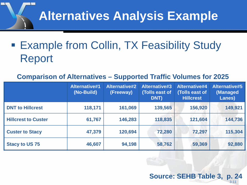
Alternatives Analysis Example
Example from Collin, TX Feasibility Study Report
Source: SEHB Table 3, p. 24
Comparison of Alternatives – Supported Traffic Volumes for 2025 Alternative#1
(No-Build) Alternative#2
(Freeway) Alternative#3 (Tolls east of
DNT)
Alternative#4 (Tolls east of
Hillcrest
Alternative#5 (Managed
Lanes)
DNT to Hillcrest 118,171 161,069 139,565 156,920 149,921
Hillcrest to Custer 61,767 146,283 118,835 121,604 144,736
Custer to Stacy 47,379 120,694 72,280 72,297 115,304
Stacy to US 75 46,607 94,198 58,762 59,369 92,880
3-12
Feasibility Study/ Concept Exploration Benefits
Considers alternatives prior to significant investment Reduces risk of cost and schedule overruns
Project feasibility is verified Project risks are identified
Use where Feasibility is in question Fundamentally different alternatives exist
3-13
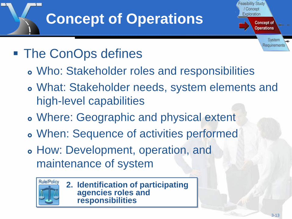
Concept of Operations
The ConOps defines Who: Stakeholder roles and responsibilities What: Stakeholder needs, system elements and
high-level capabilities Where: Geographic and physical extent When: Sequence of activities performed How: Development, operation, and
maintenance of system
2. Identification of participating
agencies roles and responsibilities
3-14
Concept of Operations (cont’d)
Key activities Identify stakeholders Define core group responsible for creating
ConOps Develop initial ConOps, review with broader
stakeholder group and iterate Define stakeholder needs Create a System Validation Plan
3-15
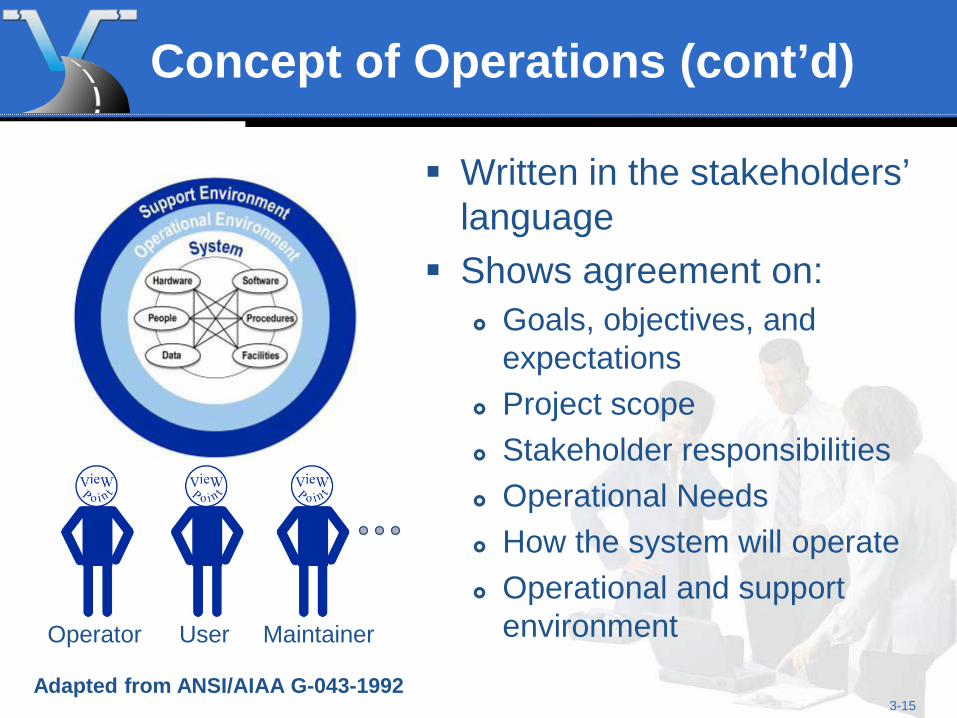
Concept of Operations (cont’d)
Written in the stakeholders’ language
Shows agreement on: Goals, objectives, and
expectations Project scope Stakeholder responsibilities Operational Needs How the system will operate Operational and support
environment Operator Maintainer User
Adapted from ANSI/AIAA G-043-1992
3-16
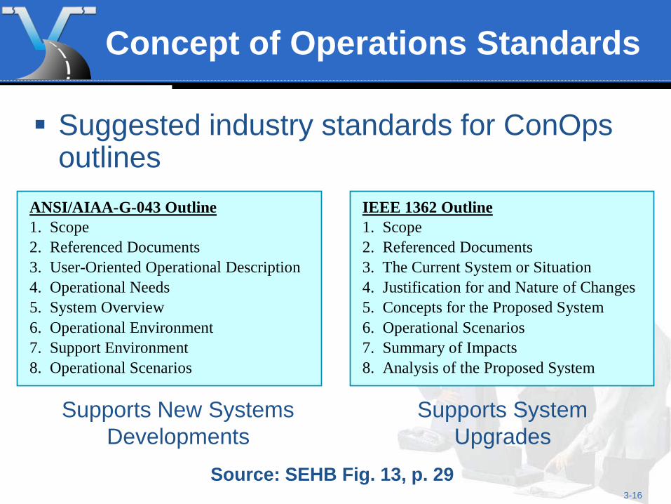
Concept of Operations Standards
Suggested industry standards for ConOps outlines
IEEE 1362 Outline 1. Scope 2. Referenced Documents 3. The Current System or Situation 4. Justification for and Nature of Changes 5. Concepts for the Proposed System 6. Operational Scenarios 7. Summary of Impacts 8. Analysis of the Proposed System
ANSI/AIAA-G-043 Outline 1. Scope 2. Referenced Documents 3. User-Oriented Operational Description 4. Operational Needs 5. System Overview 6. Operational Environment 7. Support Environment 8. Operational Scenarios Supports New Systems
Developments Supports System
Upgrades Source: SEHB Fig. 13, p. 29
3-17
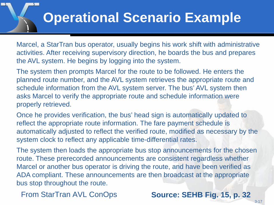
Operational Scenario Example
From StarTran AVL ConOps Source: SEHB Fig. 15, p. 32
Marcel, a StarTran bus operator, usually begins his work shift with administrative activities. After receiving supervisory direction, he boards the bus and prepares the AVL system. He begins by logging into the system. The system then prompts Marcel for the route to be followed. He enters the planned route number, and the AVL system retrieves the appropriate route and schedule information from the AVL system server. The bus’ AVL system then asks Marcel to verify the appropriate route and schedule information were properly retrieved. Once he provides verification, the bus’ head sign is automatically updated to reflect the appropriate route information. The fare payment schedule is automatically adjusted to reflect the verified route, modified as necessary by the system clock to reflect any applicable time-differential rates. The system then loads the appropriate bus stop announcements for the chosen route. These prerecorded announcements are consistent regardless whether Marcel or another bus operator is driving the route, and have been verified as ADA compliant. These announcements are then broadcast at the appropriate bus stop throughout the route.
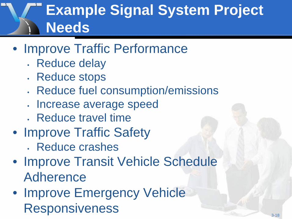
Example Signal System Project Needs
• Improve Traffic Performance • Reduce delay • Reduce stops • Reduce fuel consumption/emissions • Increase average speed • Reduce travel time
• Improve Traffic Safety • Reduce crashes
• Improve Transit Vehicle Schedule Adherence
• Improve Emergency Vehicle Responsiveness
3-18
3-19
Benefits of Developing a Concept of Operations
Early stakeholder agreement on: System capabilities Roles and responsibilities Key performance measures and a basic plan
for system validation Manage stakeholder expectations
Start with Your Eye on the Finish Line A ConOps helps the project team visualize the final system at the beginning of the project.
3-20
System Requirements
“Something that governs what, how well, and under what conditions a product will achieve a given purpose”
-- EIA-632, Electronics Industry Association Standard “Processes for Engineering a System”
3. Requirements definitions
3-21
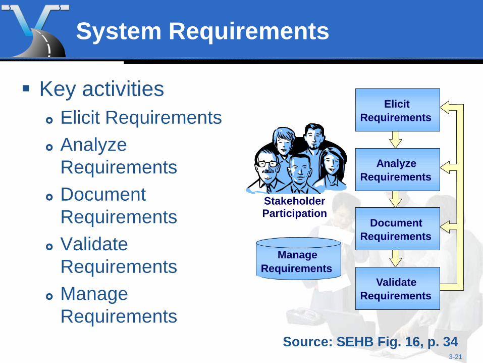
System Requirements
Key activities Elicit Requirements Analyze
Requirements Document
Requirements Validate
Requirements Manage
Requirements Source: SEHB Fig. 16, p. 34
Elicit Requirements
Analyze Requirements
Document Requirements
Validate Requirements
Manage Requirements
Elicit Requirements
Analyze Requirements
Document Requirements
Validate Requirements
Stakeholder
Stakeholder Participation
Manage Requirements
3-22
System Requirements
More key activities Create a System Verification Plan that assures
testing, demonstration, inspection, and analysis in relation to each requirement
Create a System Acceptance Plan that describes the functionality the system must display prior to customer acceptance
3-23
Writing Style for Requirements
Use “shall” rather than “will” or “should” One requirement per sentence Avoid use of pronouns Avoid vague references such as “good
workmanship” and “proven technology”
3-24
Quality Requirements
Quality Requirements Are Necessary Unambiguous Complete Measurable Consistent Achievable Testable Technology-independent
3-25
Examples of Poor Requirements
“The system shall use radar detectors for traffic monitoring.” “State-of-the-art computers shall be used.” “The system shall manage incidents.” “All work shall be performed to the
satisfaction of the Engineer.” “Industry standard designs and components
shall be used.”
3-26
Requirements Examples (good or bad?):
“The retrieval of any single status from any field device shall not exceed 2 seconds from the initiation of the request.” “Congestion shall be reduced.” “The system user shall be able to verify
reversible lane gate status of up, down, locked, and 15º status.” “People shall feel safer about riding the
bus.”
3-27
System Requirements
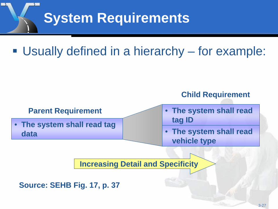
Usually defined in a hierarchy – for example:
• The system shall read tag data
• The system shall read tag ID
• The system shall read vehicle type
Increasing Detail and Specificity
Parent Requirement
Child Requirement
Source: SEHB Fig. 17, p. 37
3-28
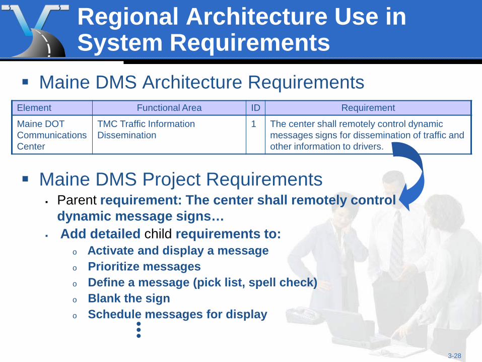
Regional Architecture Use in System Requirements
Maine DMS Architecture Requirements Element Functional Area ID Requirement
Maine DOT Communications Center
TMC Traffic Information Dissemination
1 The center shall remotely control dynamic messages signs for dissemination of traffic and other information to drivers.
Maine DMS Project Requirements Parent requirement: The center shall remotely control
dynamic message signs… Add detailed child requirements to:
o Activate and display a message o Prioritize messages o Define a message (pick list, spell check) o Blank the sign o Schedule messages for display
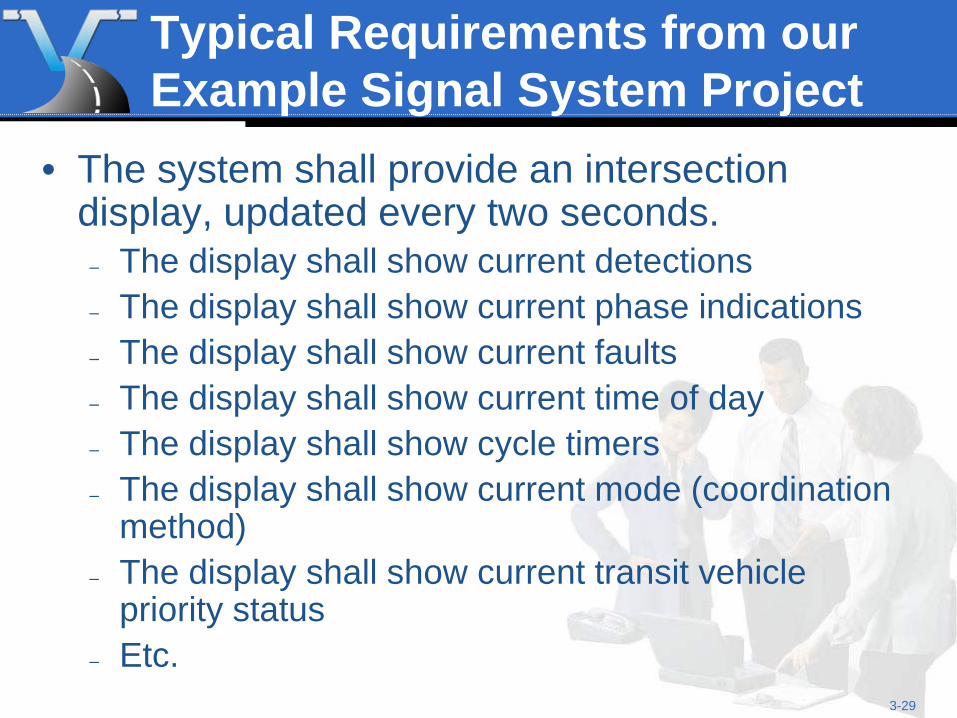
Typical Requirements from our Example Signal System Project
• The system shall provide an intersection display, updated every two seconds.
– The display shall show current detections – The display shall show current phase indications – The display shall show current faults – The display shall show current time of day – The display shall show cycle timers – The display shall show current mode (coordination
method) – The display shall show current transit vehicle
priority status – Etc.
3-29
3-30
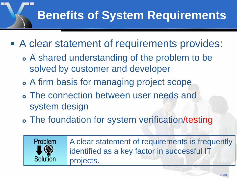
Benefits of System Requirements
A clear statement of requirements provides: A shared understanding of the problem to be
solved by customer and developer A firm basis for managing project scope The connection between user needs and
system design The foundation for system verification/testing
A clear statement of requirements is frequently identified as a key factor in successful IT projects.
3-31
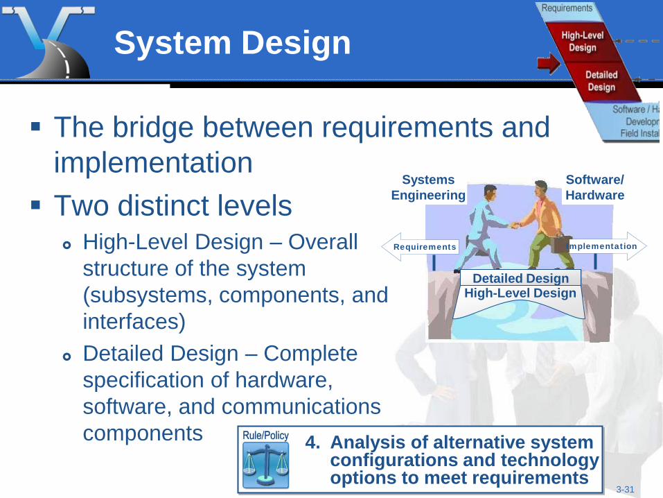
System Design
Two distinct levels
High-Level Design – Overall structure of the system (subsystems, components, and interfaces)
Detailed Design – Complete specification of hardware, software, and communications components
/
Requirements Implementation
Detailed Design
High-Level Design
Systems Engineering
Software/ Hardware
The bridge between requirements and implementation
4. Analysis of alternative system
configurations and technology options to meet requirements
3-32
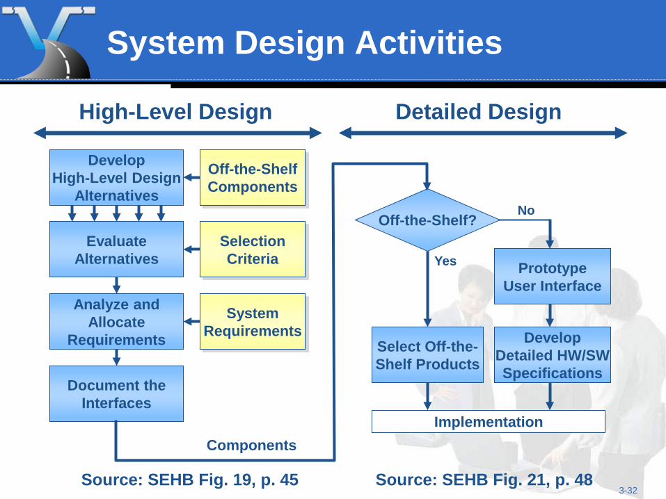
System Design Activities
Develop High-Level Design
Alternatives
Analyze and Allocate
Requirements
Selection Criteria
Evaluate Alternatives
Document the Interfaces
System Requirements
Off-the-Shelf Components
Off-the-Shelf?
Select Off-the- Shelf Products
Yes
Implementation
Develop Detailed HW/SW Specifications
Components
Prototype User Interface
No
High-Level Design Detailed Design
Source: SEHB Fig. 19, p. 45 Source: SEHB Fig. 21, p. 48
3-33
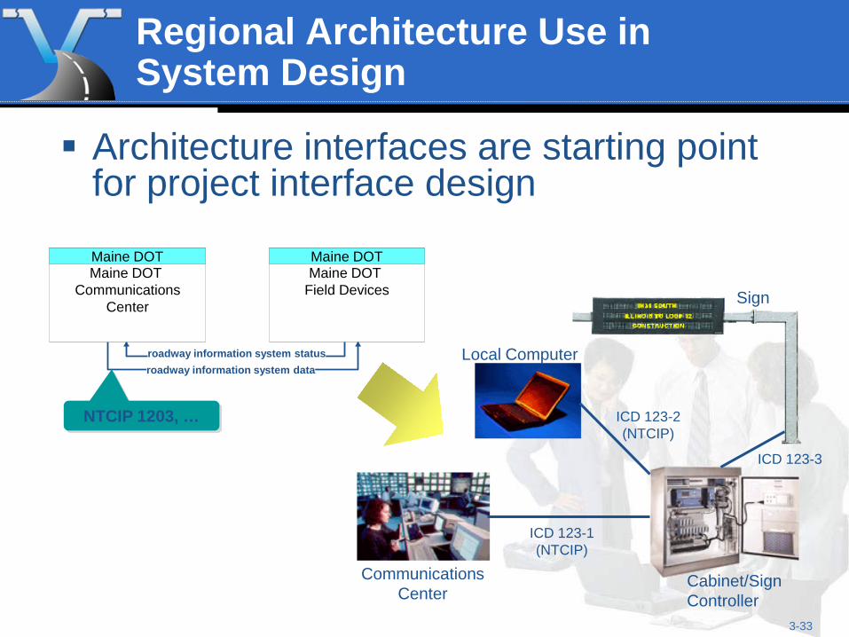
Regional Architecture Use in System Design
Architecture interfaces are starting point for project interface design
Communications Center
Cabinet/Sign Controller
Local Computer
Sign
ICD 123-1 (NTCIP)
ICD 123-2 (NTCIP)
ICD 123-3
Maine DOT Maine DOT
Field Devices
roadway information system status roadway information system data
Maine DOT Maine DOT
Communications Center
NTCIP 1203, …
3-34
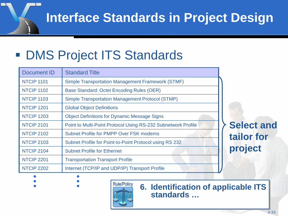
Interface Standards in Project Design
DMS Project ITS Standards Document ID Standard Title NTCIP 1101 Simple Transportation Management Framework (STMF)
NTCIP 1102 Base Standard: Octet Encoding Rules (OER)
NTCIP 1103 Simple Transportation Management Protocol (STMP)
NTCIP 1201 Global Object Definitions
NTCIP 1203 Object Definitions for Dynamic Message Signs
NTCIP 2101 Point to Multi-Point Protocol Using RS-232 Subnetwork Profile
NTCIP 2102 Subnet Profile for PMPP Over FSK modems
NTCIP 2103 Subnet Profile for Point-to-Point Protocol using RS 232
NTCIP 2104 Subnet Profile for Ethernet
NTCIP 2201 Transportation Transport Profile
NTCIP 2202 Internet (TCP/IP and UDP/IP) Transport Profile
Select and tailor for project
6. Identification of applicable ITS
standards …
3-35
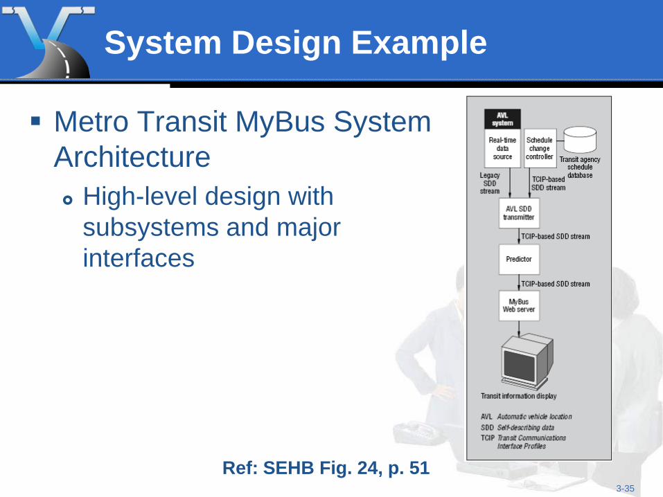
System Design Example
Metro Transit MyBus System Architecture High-level design with
subsystems and major interfaces
Ref: SEHB Fig. 24, p. 51
3-36
Benefits of System Design
A good system design: Relates requirements to the system specifications Defines open interfaces that supports different vendor
solutions and off-the-shelf products Supports efficient hardware and software development Provides a roadmap for system integration and testing Facilitates maintenance and future expansion and
upgrade of the system
A superior system design allows new technologies to be cost-effectively incorporated.
Measures of Success
The right needs and requirements are captured System satisfies all of the needs and
requirements But how do we make sure it does?
3-37
3-38
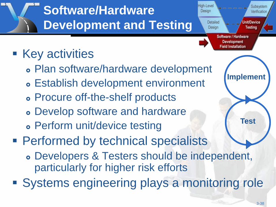
Software/Hardware Development and Testing
Key activities Plan software/hardware development Establish development environment Procure off-the-shelf products Develop software and hardware Perform unit/device testing
Performed by technical specialists Developers & Testers should be independent,
particularly for higher risk efforts Systems engineering plays a monitoring role
Implement
Test
3-39
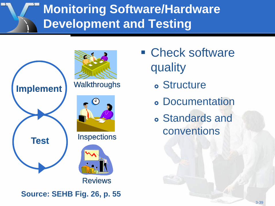
Monitoring Software/Hardware Development and Testing
Check software quality Structure Documentation Standards and
conventions
Implement
Test
Walkthroughs
Inspections
Reviews
Implement
Test
Walkthroughs
Walkthroughs
Inspections
Inspections
Reviews
Reviews
Source: SEHB Fig. 26, p. 55
3-40
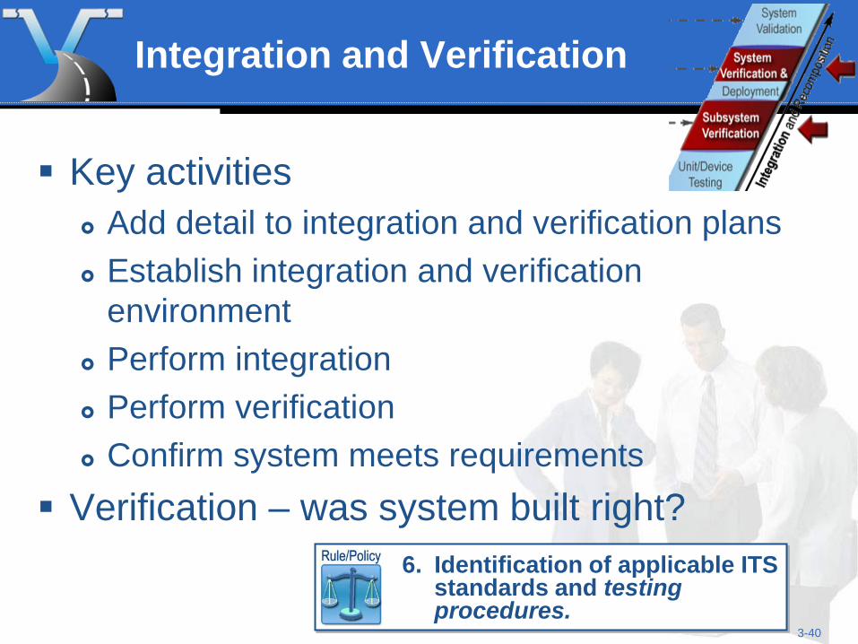
Integration and Verification
Key activities Add detail to integration and verification plans Establish integration and verification
environment Perform integration Perform verification Confirm system meets requirements
Verification – was system built right?
6. Identification of applicable ITS
standards and testing procedures.
3-41
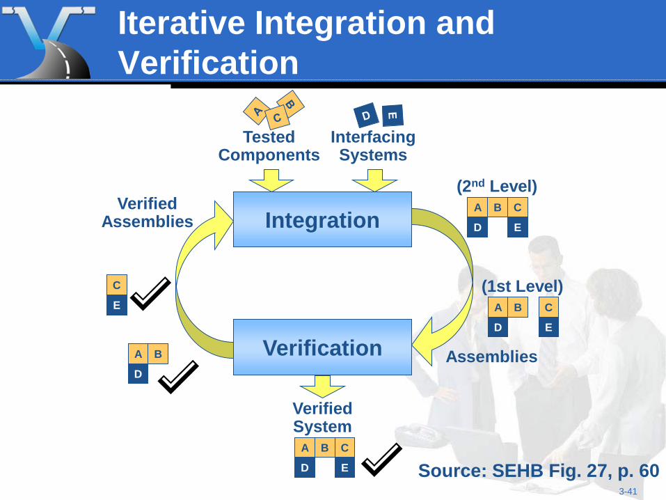
Iterative Integration and Verification
Source: SEHB Fig. 27, p. 60
Integration
Verification
Tested Components
Interfacing Systems
C
E
A B
D
Verified System
Verified Assemblies
Assemblies
C
E
A B
D
(2nd Level)
A B
D
C
E
(1st Level)
A B
D
C
E
3-42
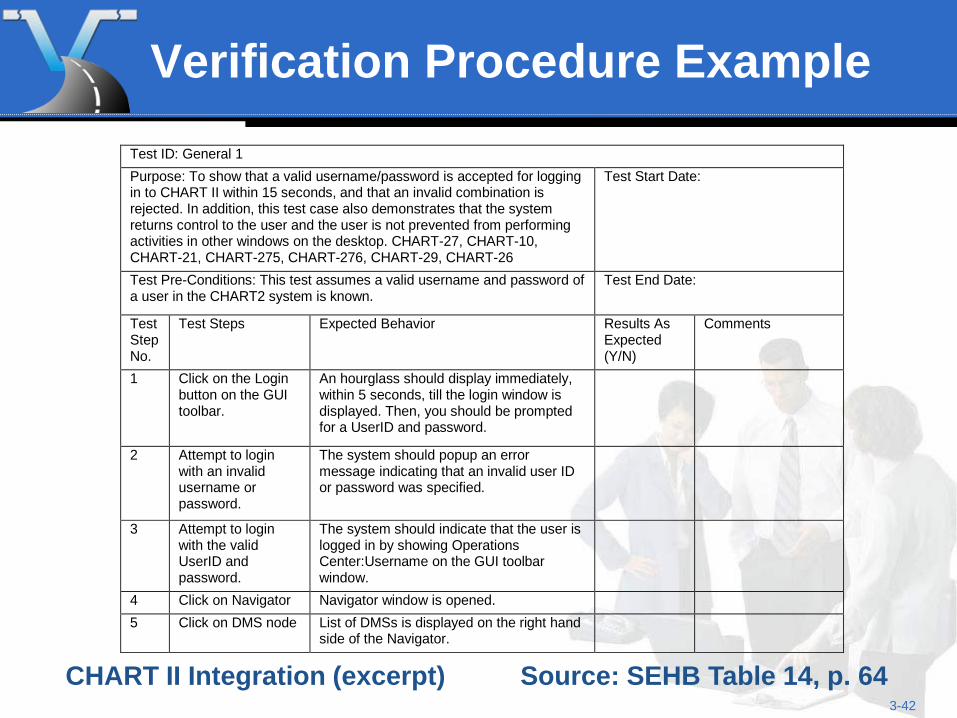
Verification Procedure Example Test ID: General 1 Purpose: To show that a valid username/password is accepted for logging in to CHART II within 15 seconds, and that an invalid combination is rejected. In addition, this test case also demonstrates that the system returns control to the user and the user is not prevented from performing activities in other windows on the desktop. CHART-27, CHART-10, CHART-21, CHART-275, CHART-276, CHART-29, CHART-26
Test Start Date:
Test Pre-Conditions: This test assumes a valid username and password of a user in the CHART2 system is known.
Test End Date:
Test Step No.
Test Steps Expected Behavior Results As Expected (Y/N)
Comments
1 Click on the Login button on the GUI toolbar.
An hourglass should display immediately, within 5 seconds, till the login window is displayed. Then, you should be prompted for a UserID and password.
2 Attempt to login with an invalid username or password.
The system should popup an error message indicating that an invalid user ID or password was specified.
3 Attempt to login with the valid UserID and password.
The system should indicate that the user is logged in by showing Operations Center:Username on the GUI toolbar window.
4 Click on Navigator Navigator window is opened. 5 Click on DMS node List of DMSs is displayed on the right hand
side of the Navigator.
Source: SEHB Table 14, p. 64 CHART II Integration (excerpt)
3-43
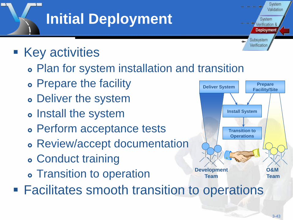
Initial Deployment
Key activities Plan for system installation and transition Prepare the facility Deliver the system Install the system Perform acceptance tests Review/accept documentation Conduct training Transition to operation
Facilitates smooth transition to operations
O&M Team
Development Team
Deliver System Prepare Facility/Site
Install System
Transition to Operations
3-44
System Validation
Validation – was the right system built? Confirm that user needs are met by the
installed system Key activities
Update Validation Plan as necessary and develop procedures
Validate system Document validation results including any
recommendations or corrective actions
3-45
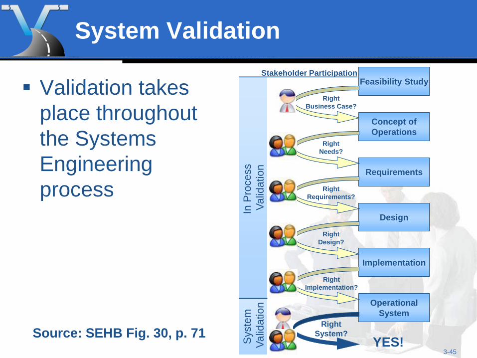
System Validation
Validation takes place throughout the Systems Engineering process
Source: SEHB Fig. 30, p. 71
In P
roce
ss
Valid
atio
n S
yste
m
Val
idat
ion
Requirements
Feasibility Study
Concept of Operations
Design
Implementation
Operational System
Right Business Case?
Right Needs?
Right Requirements?
Right Design?
Right Implementation?
Right System?
YES!
Stakeholder Participation
3-46
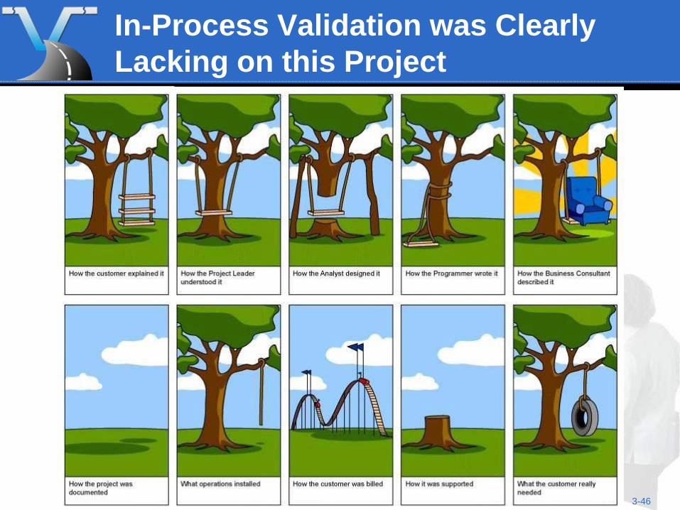
In-Process Validation was Clearly Lacking on this Project
3-47
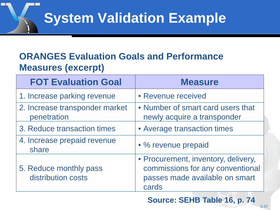
System Validation Example
FOT Evaluation Goal Measure 1. Increase parking revenue • Revenue received 2. Increase transponder market
penetration • Number of smart card users that
newly acquire a transponder 3. Reduce transaction times • Average transaction times 4. Increase prepaid revenue
share • % revenue prepaid
5. Reduce monthly pass distribution costs
• Procurement, inventory, delivery, commissions for any conventional passes made available on smart cards
Source: SEHB Table 16, p. 74
ORANGES Evaluation Goals and Performance Measures (excerpt)
3-48
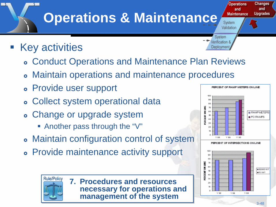
Operations & Maintenance
Key activities Conduct Operations and Maintenance Plan Reviews Maintain operations and maintenance procedures Provide user support Collect system operational data Change or upgrade system
Another pass through the “V”
Maintain configuration control of system Provide maintenance activity support
7. Procedures and resources
necessary for operations and management of the system
3-49
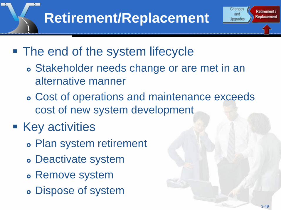
Retirement/Replacement
The end of the system lifecycle Stakeholder needs change or are met in an
alternative manner Cost of operations and maintenance exceeds
cost of new system development Key activities
Plan system retirement Deactivate system Remove system Dispose of system
3-50
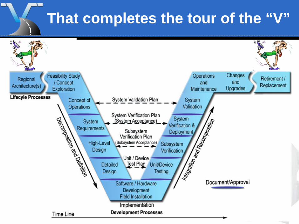
That completes the tour of the “V”
3-51
Learning Outcome
Explain the “V” Process