Embed Size (px)
Citation preview

Text (XXL)
• Design concepts – How does an island offshore look
• Design verification – How do we know the design is robust enough
• Constructability – How can we built an island in the middle of the North Sea
Session 4 part Feasible Design & Construction approach
1
Topics

Text (XXL)
- Protection against severe waves – stability and overtopping
- Extreme events (e.g. 1/100y) and operational conditions (up to yearly maximum)
- Accessibility ships – harbour needed? Quay wall / breakwater then required
- Functional space - small island versus larger island, economy of scale
Design concepts – How does an island offshore look
2
Starting points - main design aspects Jebel Ali (Dubai)
port extension
≈ 200ha
DAS Island
Ext. exisinting isl.
≈ 160ha
Production islands
Abu Dhabi
≈ 30 to 75ha

Text (XXL)
• Sand slopes+ low cost per m3 (but large volume needed)+ sand available in North Sea- maintenance needed and/or large groynes required- long slope – large area needed and large volume
• Concrete caissons+ minimise footprint (on sea floor) + pre-fabrication possible- need deep building dock or deep water for floating dock- placement difficult in waves
• Rock rubble mound revetments- large rock quantities needed+/- phased seasonal construction needed and possible+ experience in offshore and in severe conditions
• Reef / low crested breakwater> combined with cobbles / beach / floating etc. + can be combined with other functionalities or floatingisland parts, - not easily economic for small islands
Design concepts – shore protections
3
Shore protections main options

1. Climate adaptive structureThe amount of sea level rise is uncertain ➔ strategy to develop structures that can be easily adapted by enhancing the
energy dissipation.
2. Ecological enhancing structureRe-introduction of hard substrate to help habitat restoration in the North Sea
Rocks provide irregular cavities between the rocks. Wave reflection is also minimised due to the gentle slope of the energy
dissipation zone, which may benefit the ecological zone.
3. Hydraulic safetySplitting the structure in an energy dissipation zone and a final emerged structure. The emerged structure can also be shifted
backwards/ combining it with the reclaimed island
Typical revetment solution might be initially the most economical solution however with the lagoon
option more future sustainable goals may be accomplished
Design concepts – Living reef breakwater concept
Design based on 3 key objectives:

Text (XXL)
All structures need to absorb wave energy – breaking to reduce damage and wave overtopping
• Single slope revetment
• Waves break directly on main slope
• Large armour units but smaller structure
• Caisson
• Waves break directly on vertical face
• Bermed revetment
• Waves break on submerged berm
• Smaller armour (possibly rock only) but larger cross section
• Reef / lagoon system
• Waves break on (submerged) reef, lower waves in lagoon
• More wave reduction with emerged reef (enable floating)
• Large total area of island
Concept design – Wave breaking and overtopping
5

Text (XXL)
Armour units – breaking the high waves
- Rock – very heavy, berm or re-shaping
- Concrete units
- Xbloc / Accropode / Cube / Cubipod etc.
- Reef / lagoon example
Rock and/or concrete armour
Concept designs – Armour unit options
6
Revetment / reef examples

Text (XXL)
1. Design conditions based on extensive measurements and hindcast databases combined with extreme value analysis
2. Designs prepared based on design formulae (stability / overtopoping) and/or numerical models (e.g. currents and morphological impacts
3. Verification of stability and wave overtopping in physical scale model tests
Design verification – Physical model tests
7
Concepts > Detailed Designs > verification

Text (XXL)
- Manufacturing:
- Onshore factory > launch slide or subm. vessel
- (deep) building dry dock > float out
- Floating dock sliding formwork > float out
- Placement
- Transport to site with tugs or subm. Vessel
- Placement, sink by filling above rock-bed
- Challenges
- Suitable construction location (deep / sheltered)
- Placement in wave conditions
Constructability
8
Caisson manufacture and placement

Text (XXL)
- Manufacturing:
- Rock quarries (e.g. Southern Norway), transport by barge / bulk carrier
- Concrete armour units batching plant, regional port
- Placement
- Subsea rock installation vessels / side stone dumping vessels / split barges
- Once “dry feet”, cranes on land i.c.w. floating cranes
- Challenges
- High production rates needed > stock-piling at quarry or transfer location
- Workability floating equipment > select suitable vessels / stop in winter
- Damage to core / underlayers > heavier core / short work fronts
Constructability
9
Rock rubble mound revetments
Text (XXL)
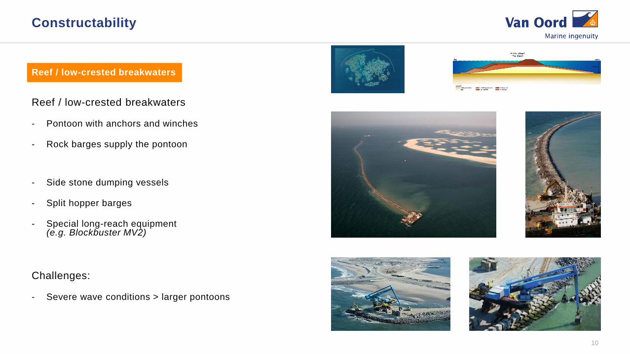
Reef / low-crested breakwaters
- Pontoon with anchors and winches
- Rock barges supply the pontoon
- Side stone dumping vessels
- Split hopper barges
- Special long-reach equipment(e.g. Blockbuster MV2)
Challenges:
- Severe wave conditions > larger pontoons
Constructability
10
Reef / low-crested breakwaters
Text (XXL)
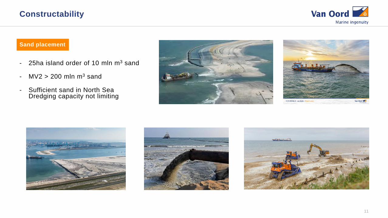
- 25ha island order of 10 mln m3 sand
- MV2 > 200 mln m3 sand
- Sufficient sand in North SeaDredging capacity not limiting
Constructability
11
Sand placement