Embed Size (px)
Citation preview

Session 6
2014 BiTS Workshop ~ March 9 – 12, 2014
Wednesday 3/12/14 8:00am
INTERCONNECTOLOGY: IT’S WHAT WE DO
Last Year's BiTS workshop introduced the benefits from the Interconnectology approach of collaboration across the supply chain from device design to test. This session focuses on interconnect designs and advancements. As contactor design has had to evolve to address shrinking pads and decreasing pitches, there's lower contact force. The first presenter then asks whether contact pressure has become more meaningful than contact force. The second presentation details the development of long-life stamped spring probes in response to challenging technology roadmaps, all at a cost that includes maintenance and replacement costs. Next up is a paper on validations sockets (used for post-silicon validation and are quite different from test sockets). This paper brings awareness to these sockets and their challenges to encourage industry collaboration for solving future post-silicon validation interconnect challenges. The session concludes with an exploration of crosstalk sources and discusses solutions and emerging technologies, including costs, to reduce crosstalk. See? It's all about Interconnectology.
Long Life / Stamped Spring Probe Development Samuel Pak, A.J. Park—IWIN Co. Ltd.
Validation Interconnect Socket — Application and Future Challenges Ashok Kabadi—Intel Corporation
Crosstalk Mitigation in ATE Socket-Device Interface Boards Thomas P. Warwick—R&D Altanova, Inc.
COPYRIGHT NOTICE The paper(s) in this publication comprise the Proceedings of the 2014 BiTS Workshop. The content reflects the opinion of the authors and their respective companies. They are reproduced here as they were presented at the 2014 BiTS Workshop. This version of the papers may differ from the version that was distributed in hardcopy & softcopy form at the 2014 BiTS Workshop. The inclusion of the papers in this publication does not constitute an endorsement by BiTS Workshop, LLC or the workshop’s sponsors.
There is NO copyright protection claimed on the presentation content by BiTS Workshop, LLC. (Occasionally a Tutorial and/or TechTalk may be copyrighted by the author). However, each presentation is the work of the authors and their respective companies: as such, it is strongly encouraged that any use reflect proper acknowledgement to the appropriate source. Any questions regarding the use of any materials presented should be directed to the author(s) or their companies.
The BiTS logo and ‘Burn-in & Test Strategies Workshop’ are trademarks of BiTS Workshop, LLC. All rights reserved.
This Paper

2014 BiTS Workshop ~ March 9 - 12, 2014
Paper #11
Interconnectology: It's What We Do
Session 6
Long Life / Stamped Spring Probe Development
2014 BiTS Workshop
March 9 - 12, 2014
Samuel Pak IWIN Co, Ltd.AJ Park IWIN Co, Ltd
Conference Ready 02/12/2014
Content
• Update Previous presentations
• Design considerations for a long life pin
• Mechanical life vs. Contact resistance
• Destructive tests and lessons learned
• Life test with actual device loading
• RF and Impedance performance
• Summaries and the next step
BiTS 2014 2Long Life / Stamped Spring Probe Development

2014 BiTS Workshop ~ March 9 - 12, 2014
Paper #12
Interconnectology: It's What We Do
Session 6
Previous Presentation Summary
Three Pieces Spring Probes
Note : Refer to BiTS 2013 presentationfor details and how to make
One Piece Spring Probe0.10mm
BiTS 2014 3Long Life / Stamped Spring Probe Development
Previous Presentation UpdateOne piece Spring Probe – Motion picture
Signal Path
Cylindrical Crown
δ
Low Cost Version
1.6 mm
BiTS 2014 4Long Life / Stamped Spring Probe Development

2014 BiTS Workshop ~ March 9 - 12, 2014
Paper #13
Interconnectology: It's What We Do
Session 6
Design Consideration to Increase the Life of Spring Probe
– Special alloy for crown tip and pin body
– High hardness carbon coat on tips
– Tip shape to eliminate contamination
– Pin design to maximize space for spring
– Pin shape enabling bigger spring diameter
BiTS 2014 5Long Life / Stamped Spring Probe Development
Design ConsiderationsSpring Design
Working stroke
δ ∝ D^3 ( spring diameter )
∝ reverse of d^3 (wire diameter)
∝ number of turns
Spring force
F ∝ d^3
∝ reverse of D^3∝ Travelling distance
BiTS 2014 6Long Life / Stamped Spring Probe Development

2014 BiTS Workshop ~ March 9 - 12, 2014
Paper #14
Interconnectology: It's What We Do
Session 6
Design ConsiderationsSpring Design
- Bigger spring diameter enables to increase stress
ratio greatly
- For a longer life design, stress ratio should be lower than 30%
- To improve the stress ratio, number of turns should be increased.
- For high working temperature, above 130 degree C, music wire or Be-Cu shall not be chosen.
BiTS 2014 7Long Life / Stamped Spring Probe Development
Part No of pin to be tested: HPSP33465C4
HPSP platform outlines
1. Stable Signal path by pinched sliding
2. Enabling Short length, 1.2mm, good for high speed application
3. Enabling Small diameter, good for finer pitch, 0.15mm pitch
4. High current carrying, 4.5 Amps in 0.4mm pitch, 3.3mm length pin
5. 0.8mm traveling in 3.3 mm length
6. Progressive stamping enabling low cost
Chosen Pin for the Test
Signal PathSignal Path
X
X2. Shorter
Larger 3. Smaller
Current HPSP
BiTS 2014 8Long Life / Stamped Spring Probe Development

2014 BiTS Workshop ~ March 9 - 12, 2014
Paper #15
Interconnectology: It's What We Do
Session 6
Test Settings and Measurements
Device used for testing: FBGA 216
Pins tried this time: HPSP33465C4
1. Reliability test (Mechanical) 300ku of insertions
2. Life test (Actual device loading) 150ku of insertions
3. Destructive test for 20 pins 2 millions of insertions
4. Current carrying capacity
5. Signal quality data (Impedance, RF performance)
BiTS 2014 9Long Life / Stamped Spring Probe Development
Durability Test – 300k Cycles Gold plating 0.4µ thick
Test condition Cycle number : 300,000 times Contacted electrode: Au plate Stroke: 0.27mm (Preloaded 0.05mm)
Unused
300k
mΩ
10Long Life / Stamped Spring Probe DevelopmentBiTS 2014

2014 BiTS Workshop ~ March 9 - 12, 2014
Paper #16
Interconnectology: It's What We Do
Session 6
Tough Conductive Coating on tipTest condition Cycle number : 300,000 times Contacted electrode: Au plate Stroke: 0.45mm (Preloaded 0.15mm)
Unused
300k
mΩ
Durability Test – 300k Cycles
11Long Life / Stamped Spring Probe DevelopmentBiTS 2014
Durability Test – 300k Cycles Upper plunger by Pd alloy (No gold plating)
Test condition Cycle number : 300,000 times Contacted electrode: Au plate Stroke: 0.40mm (Preloaded 0.15mm)
mΩ Unused
300k
12Long Life / Stamped Spring Probe DevelopmentBiTS 2014

2014 BiTS Workshop ~ March 9 - 12, 2014
Paper #17
Interconnectology: It's What We Do
Session 6
Destructive TestHPSP33465C4
Unused 300K 600K
Sliding surface condition
2M
13Long Life / Stamped Spring Probe DevelopmentBiTS 2014
* Test condition: Ambient temp (25 Degree C)
* Test method: Started from 1Amp and increase
1 Amp by every one minute
* Measure allowable current carrying:
- Any change in mechanical condition, Contact force
- Burn
- Permanent deflection
V
A
Current Carrying Capacity Measuring
Product HPSP33465 HPSP51113
Overall Length 4.65mm 1.13mm
Current CarryingCapacity
4.5A 8.1A
BiTS 2014 14Long Life / Stamped Spring Probe Development

2014 BiTS Workshop ~ March 9 - 12, 2014
Paper #18
Interconnectology: It's What We Do
Session 6
Life Test Report From S Company(Contact Stroke : 0.3mm Device0.15mm PCB)
Contact testInitial 50K 90K 110K 130K 150K
Life timeTest
1 Top Damage
2 Pin Force [g] 21.31 22.07 21.79 21.91 21.95 21.643
Resistance [mΩ] 62.12 80.89 80.13 106.54 104.14 107.43
Ball mark Acceptable
Note: 1. Checked spring force and CRES at every10k insertions2. CRES showed stable thru out the test period3. Stopped test due to open failure at 150ku insertions
BiTS 2014 15Long Life / Stamped Spring Probe Development
RF Performance and Impedance CheckBy S Customer
RF Performance test & Pin Impedance check Test Method
- Same Module Device package use RF Performance test and Impedance Check(RF Test time 1K)- RF Performance test result : Up to 1K RF Performance CPK 133 Secure- Every testing item SPEC Margin secure- After 1K test POGO Pin Impedance check average 0.01Ω
Pin No# 0 time 1K
A1 0.09 0.08A4 0.09 0.07A8 0.13 0.14B2 0.07 0.06F8 0.08 0.11J8 0.15 0.14M1 0.18 0.14M8 0.08 0.07N7 0.08 0.07P1 0.11 0.11P7 0.15 0.14P8 0.11 0.11
Average 0.11 0.10 Min 0.07 0.06 Max 0.18 0.14
Pin Impedance check
BiTS 2014 16Long Life / Stamped Spring Probe Development

2014 BiTS Workshop ~ March 9 - 12, 2014
Paper #19
Interconnectology: It's What We Do
Session 6
Impedance Check According to Durability Test By S Customer
Testing MethodPusher pressure 0.35MPA, pushing time 30sec every 1,000 times, each IWIN Pin Impedance check
IWIN Pin Impedance check Average 0.01ΩPin No# 0 times 1K 2K 3K 4K 5K
A1 0.12 0.11 0.12 0.12 0.12 0.11
A4 0.05 0.08 0.10 0.10 0.10 0.09
A8 0.07 0.06 0.06 0.07 0.11 0.09
B2 0.10 0.09 0.09 0.09 0.09 0.09
F8 0.09 0.07 0.08 0.09 0.09 0.08
J8 0.13 0.11 0.10 0.13 0.12 0.11
M1 0.07 0.05 0.06 0.07 0.07 0.09
M8 0.08 0.07 0.07 0.09 0.10 0.1
N7 0.08 0.08 0.08 0.07 0.09 0.1
P1 0.14 0.13 0.14 0.13 0.13 0.12
P7 0.15 0.12 0.11 0.12 0.10 0.12
P8 0.09 0.09 0.11 0.12 0.13 0.14
Average 0.10 0.09 0.09 0.10 0.10 0.10
Min 0.05 0.05 0.06 0.07 0.07 0.08
Max 0.15 0.13 0.14 0.13 0.13 0.14
IWIN Pin Impedance
IWIN Pin Impedance
BiTS 2014 17Long Life / Stamped Spring Probe Development
Test Item Ch Current Pin IWIN PIN
TX PowerCh 1 1.24 1.35
Ch 7 1.47 1.37
Ch 13 1.43 1.39
EVM
Ch 1 3.39 6.14
Ch 7 3.44 4.90
Ch 13 3.70 4.59
50dBr Mask _L
Ch 1 8.62 6.32
Ch 7 9.04 7.47
Ch 13 7.78 7.93
30dBr Mask _L
Ch 1 3.46 3.23
Ch 7 3.50 3.43
Ch 13 3.50 3.43
30dBr Mask _R
Ch 1 3.77 3.56
Ch 7 3.78 3.68
Ch 13 3.82 3.94
50dBr Mask _R
Ch 1 6.21 6.81
Ch 7 9.24 6.36
Ch 13 6.15 7.45
RF Performance CheckBy S Customer
1) RF Performance Check CPK 1.33 SecureCh Current Pin IWIN PIN
TX PowerCh 1 1.32 1.71Ch 7 1.36 1.75Ch 13 1.37 2.06
EVMCh 1 1.65 1.92Ch 7 1.59 1.86Ch 13 1.36 1.99
40dBr Mask _L Ch 1 5.37 5.06Ch 7 6.02 5.95Ch 13 5.97 5.98
28dBr Mask _L Ch 1 4.09 3.22Ch 7 3.92 3.66Ch 13 3.98 3.68
20dBr Mask _L Ch 1 4.89 3.41Ch 7 5.00 4.72Ch 13 5.34 4.62
20dBr Mask _RCh 1 4.31 4.19Ch 7 5.54 4.45Ch 13 4.37 4.94
28dBr Mask _RCh 1 3.73 3.61Ch 7 6.02 3.10Ch 13 3.70 3.57
40dBr Mask _RCh 1 8.35 7.89Ch 7 5.53 7.44Ch 13 7.70 6.60
Ch Current Pin IWIN PIN
TX PowerCh 36 1.50 1.63Ch 100 1.41 1.54Ch 161 1.35 1.54
EVMCh 36 1.39 1.90Ch 100 1.37 1.97Ch 161 1.34 1.38
40dBr Mask _L Ch 36 4.69 1.91Ch 100 3.37 3.10Ch 161 4.78 4.16
28dBr Mask _L Ch 36 3.28 1.60Ch 100 3.47 2.72Ch 161 2.54 1.72
20dBr Mask _L Ch 36 3.73 1.64Ch 100 4.71 2.64Ch 161 3.23 2.10
20dBr Mask _RCh 36 3.67 1.66Ch 100 3.27 3.41Ch 161 2.09 2.05
28dBr Mask _RCh 36 3.41 1.66Ch 100 3.26 3.19Ch 161 1.96 1.85
40dBr Mask _RCh 36 5.06 1.92Ch 100 4.23 3.91Ch 161 4.75 4.33
2.4 11b 2.4 11g 5 11a
BiTS 2014 18Long Life / Stamped Spring Probe Development
2014 BiTS Workshop ~ March 9 - 12, 2014
Paper #110
Interconnectology: It's What We Do
Session 6
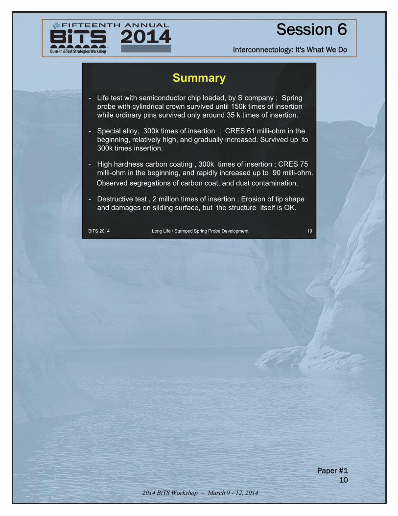
Summary
- Life test with semiconductor chip loaded, by S company ; Spring probe with cylindrical crown survived until 150k times of insertion while ordinary pins survived only around 35 k times of insertion.
- Special alloy, 300k times of insertion ; CRES 61 milli-ohm in the beginning, relatively high, and gradually increased. Survived up to 300k times insertion.
- High hardness carbon coating , 300k times of insertion ; CRES 75 milli-ohm in the beginning, and rapidly increased up to 90 milli-ohm.
Observed segregations of carbon coat, and dust contamination.
- Destructive test , 2 million times of insertion ; Erosion of tip shape and damages on sliding surface, but the structure itself is OK.
BiTS 2014 19Long Life / Stamped Spring Probe Development