Embed Size (px)
Citation preview
International ConferenceNuclear Energy in Central Europe 2001Hoteli Bernardin, Portorož, Slovenia, September 10-13, 2001www: http://www.drustvo-js.si/port2001/ e-mail:[email protected].:+ 386 1 588 5247, + 386 1 588 5311 fax:+ 386 1 561 2335Nuclear Society of Slovenia, PORT2001, Jamova 39, SI-1000 Ljubljana, Slovenia
614.1
SETTING OF THE APPARATUS FOR IRRADIATION OFSAMPLES WITH FAST NEUTRONS IN THE EXPOSUREROOM OF TRIGA MARK II REACTOR IN LJUBLJANA
Edvard S. Krištof“Jožef Stefan” Institute
Reactor Physics DivisionJamova 39, SI-1000 Ljubljana, Slovenia
ABSTRACT
In this paper the arising of a device for irradiation of samples with fission neutrons isdescribed. Also fast neutron spectra in several irradiation positions are given.
1 INTRODUCTION
Apparatus is positioned in the exposure room of the reactor. The essential piece of thedevice is a fission plate with the diameter of 25 cm. It contains 294 grams of the isotope 235U.Construction materials of the exposed parts of the device were chosen so that after 40 years ofoperation it will not be classified as a radioactive matter.
2 IRRADIATION SET-UP
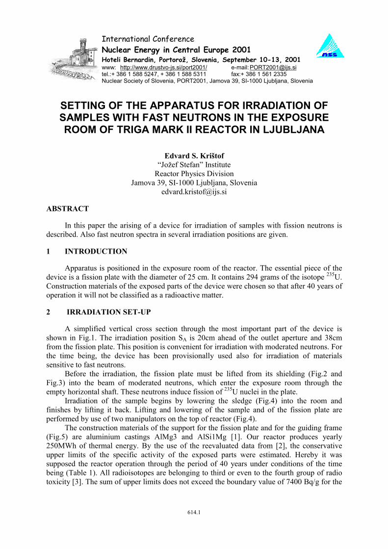
A simplified vertical cross section through the most important part of the device isshown in Fig.1. The irradiation position SA is 20cm ahead of the outlet aperture and 38cmfrom the fission plate. This position is convenient for irradiation with moderated neutrons. Forthe time being, the device has been provisionally used also for irradiation of materialssensitive to fast neutrons.
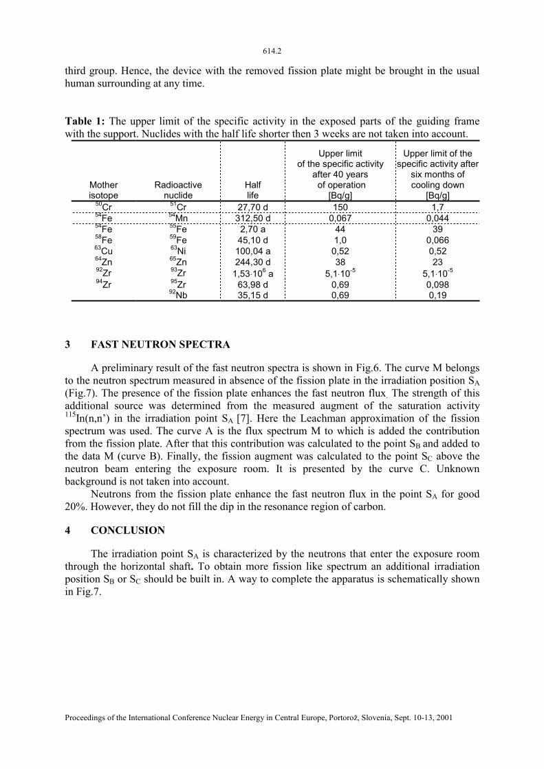
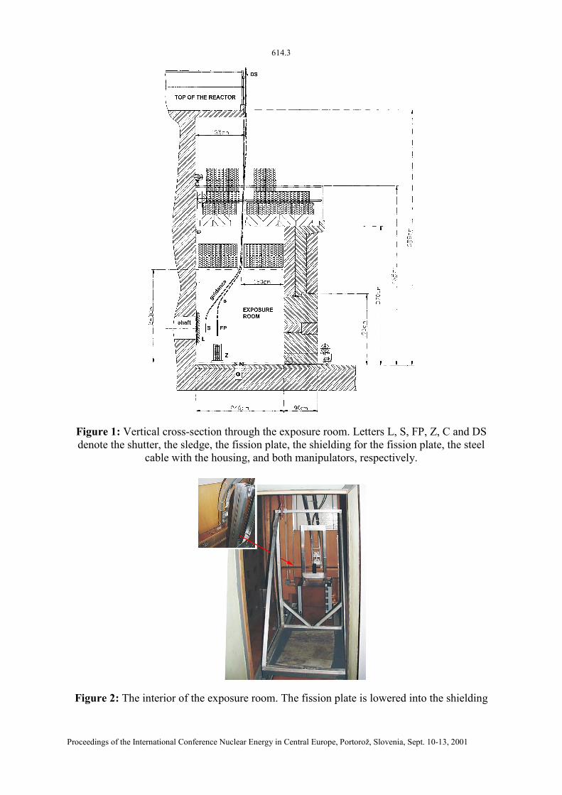
Before the irradiation, the fission plate must be lifted from its shielding (Fig.2 andFig.3) into the beam of moderated neutrons, which enter the exposure room through theempty horizontal shaft. These neutrons induce fission of 235U nuclei in the plate.
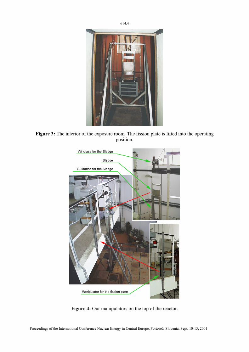
Irradiation of the sample begins by lowering the sledge (Fig.4) into the room andfinishes by lifting it back. Lifting and lowering of the sample and of the fission plate areperformed by use of two manipulators on the top of reactor (Fig.4).
The construction materials of the support for the fission plate and for the guiding frame(Fig.5) are aluminium castings AlMg3 and AlSi1Mg [1]. Our reactor produces yearly250MWh of thermal energy. By the use of the reevaluated data from [2], the conservativeupper limits of the specific activity of the exposed parts were estimated. Hereby it wassupposed the reactor operation through the period of 40 years under conditions of the timebeing (Table 1). All radioisotopes are belonging to third or even to the fourth group of radiotoxicity [3]. The sum of upper limits does not exceed the boundary value of 7400 Bq/g for the
614.2
Proceedings of the International Conference Nuclear Energy in Central Europe, Portorož, Slovenia, Sept. 10-13, 2001
third group. Hence, the device with the removed fission plate might be brought in the usualhuman surrounding at any time.
Table 1: The upper limit of the specific activity in the exposed parts of the guiding framewith the support. Nuclides with the half life shorter then 3 weeks are not taken into account.
Motherisotope
Radioactivenuclide
Halflife
Upper limitof the specific activity
after 40 years of operation
[Bq/g]
Upper limit of thespecific activity after
six months ofcooling down
[Bq/g]50Cr 51Cr 27,70 d 150 1,754Fe 54Mn 312,50 d 0,067 0,04454Fe 55Fe 2,70 a 44 3958Fe 59Fe 45,10 d 1,0 0,06663Cu 63Ni 100,04 a 0,52 0,5264Zn 65Zn 244,30 d 38 2392Zr 93Zr 1,53⋅106 a 5,1⋅10-5 5,1⋅10-5
94Zr 95Zr92Nb
63,98 d35,15 d
0,690,69
0,0980,19
3 FAST NEUTRON SPECTRA
A preliminary result of the fast neutron spectra is shown in Fig.6. The curve M belongsto the neutron spectrum measured in absence of the fission plate in the irradiation position SA(Fig.7). The presence of the fission plate enhances the fast neutron flux. The strength of thisadditional source was determined from the measured augment of the saturation activity115In(n,n’) in the irradiation point SA [7]. Here the Leachman approximation of the fissionspectrum was used. The curve A is the flux spectrum M to which is added the contributionfrom the fission plate. After that this contribution was calculated to the point SB and added tothe data M (curve B). Finally, the fission augment was calculated to the point SC above theneutron beam entering the exposure room. It is presented by the curve C. Unknownbackground is not taken into account.
Neutrons from the fission plate enhance the fast neutron flux in the point SA for good20%. However, they do not fill the dip in the resonance region of carbon.
4 CONCLUSION
The irradiation point SA is characterized by the neutrons that enter the exposure roomthrough the horizontal shaft. To obtain more fission like spectrum an additional irradiationposition SB or SC should be built in. A way to complete the apparatus is schematically shownin Fig.7.
614.3
Proceedings of the International Conference Nuclear Energy in Central Europe, Portorož, Slovenia, Sept. 10-13, 2001
Figure 1: Vertical cross-section through the exposure room. Letters L, S, FP, Z, C and DSdenote the shutter, the sledge, the fission plate, the shielding for the fission plate, the steel
cable with the housing, and both manipulators, respectively.
Figure 2: The interior of the exposure room. The fission plate is lowered into the shielding
614.4
Proceedings of the International Conference Nuclear Energy in Central Europe, Portorož, Slovenia, Sept. 10-13, 2001
Figure 3: The interior of the exposure room. The fission plate is lifted into the operatingposition.
Figure 4: Our manipulators on the top of the reactor.
614.5
Proceedings of the International Conference Nuclear Energy in Central Europe, Portorož, Slovenia, Sept. 10-13, 2001
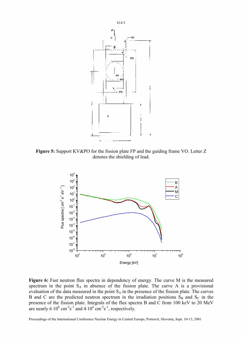
Figure 5: Support KV&PO for the fission plate FP and the guiding frame VO. Letter Zdenotes the shielding of lead.
104 105 106 107 10810-8
10-7
10-6
10-5
10-4
10-3
10-2
10-1
100
101
102
103
104
Flux
spe
ctra
[ cm
-2 s
-1 e
V -1 ]
Energy [eV]
B A M C
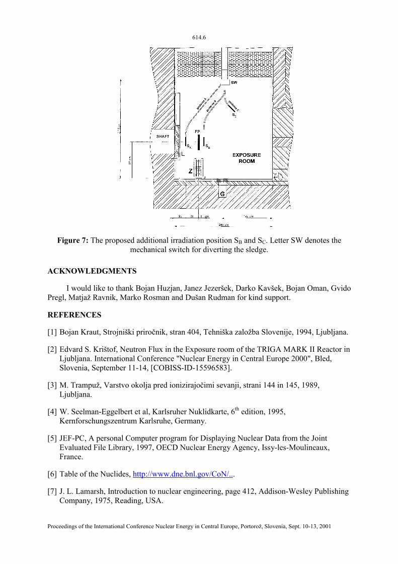
Figure 6: Fast neutron flux spectra in dependency of energy. The curve M is the measuredspectrum in the point SA in absence of the fission plate. The curve A is a provisionalevaluation of the data measured in the point SA in the presence of the fission plate. The curvesB and C are the predicted neutron spectrum in the irradiation positions SB and SC in thepresence of the fission plate. Integrals of the flux spectra B and C from 100 keV to 20 MeVare nearly 6⋅106 cm-2s-1 and 4⋅104 cm-2s-1, respectively.
614.6
Proceedings of the International Conference Nuclear Energy in Central Europe, Portorož, Slovenia, Sept. 10-13, 2001
Figure 7: The proposed additional irradiation position SB and SC. Letter SW denotes themechanical switch for diverting the sledge.
ACKNOWLEDGMENTS
I would like to thank Bojan Huzjan, Janez Jezeršek, Darko Kavšek, Bojan Oman, GvidoPregl, Matjaž Ravnik, Marko Rosman and Dušan Rudman for kind support.
REFERENCES
[1] Bojan Kraut, Strojniški priročnik, stran 404, Tehniška založba Slovenije, 1994, Ljubljana.
[2] Edvard S. Krištof, Neutron Flux in the Exposure room of the TRIGA MARK II Reactor inLjubljana. International Conference "Nuclear Energy in Central Europe 2000", Bled,Slovenia, September 11-14, [COBISS-ID-15596583].
[3] M. Trampuž, Varstvo okolja pred ionizirajočimi sevanji, strani 144 in 145, 1989,Ljubljana.
[4] W. Seelman-Eggelbert et al, Karlsruher Nuklidkarte, 6th edition, 1995,Kernforschungszentrum Karlsruhe, Germany.
[5] JEF-PC, A personal Computer program for Displaying Nuclear Data from the JointEvaluated File Library, 1997, OECD Nuclear Energy Agency, Issy-les-Moulineaux,France.
[6] Table of the Nuclides, http://www.dne.bnl.gov/CoN/...
[7] J. L. Lamarsh, Introduction to nuclear engineering, page 412, Addison-Wesley PublishingCompany, 1975, Reading, USA.