Embed Size (px)
Citation preview
C H A P T E R 5
Setting Up an IPS DeviceYou can configure your device in either a passive or inline IPS deployment. In a passive deployment, you deploy the system out of band from the flow of network traffic. In an inline deployment, you configure the system transparently on a network segment by binding two ports together.
The following sections describe configuring your device for passive and inline deployments of the FireSIGHT System:
• Understanding Passive IPS Deployments, page 5-1
• Configuring Passive Interfaces, page 5-1
• Understanding Inline IPS Deployments, page 5-3
• Configuring Inline Interfaces, page 5-3
• Configuring Inline Sets, page 5-4
• Configuring Cisco NGIPS for Blue Coat X-Series Interfaces, page 5-11
Understanding Passive IPS DeploymentsLicense: Protection
In a passive IPS deployment, the FireSIGHT System monitors traffic flowing across a network using a switch SPAN or mirror port. The SPAN or mirror port allows for traffic to be copied from other ports on the switch. This provides the system visibility within the network without being in the flow of network traffic. When configured in a passive deployment, the system cannot take certain actions such as blocking or shaping traffic. Passive interfaces receive all traffic unconditionally and no traffic received on these interfaces is retransmitted.
Note Outbound traffic includes flow control packets. Because of this, passive interfaces on your appliances may show outbound traffic and, depending on your configuration, generate events; this is expected behavior.
Configuring Passive InterfacesLicense: Protection
You can configure one or more physical ports on a managed device as passive interfaces.
5-1FireSIGHT System User Guide
Chapter 5 Setting Up an IPS Device Configuring Passive Interfaces
You configure Cisco NGIPS for Blue Coat X-Series interfaces as either passive or inline when installing the Cisco package. You cannot use the FireSIGHT System web interface to reconfigure Cisco NGIPS for Blue Coat X-Series interfaces. For more information, see Configuring Cisco NGIPS for Blue Coat X-Series Interfaces, page 5-11.
Caution Changing any (Series 2) or the highest (Series 3) MTU value for a sensing interface or inline set temporarily interrupts traffic inspection on all sensing interfaces on the device, not just the interface you changed, when you apply your changes. Whether traffic drops during this interruption or passes without further inspection depends on the model of the managed device and the interface type. See How Snort Restarts Affect Traffic, page 1-9.
To configure a passive interface:
Access: Admin/Network Admin
Step 1 Select Devices > Device Management.
The Device Management page appears.
Step 2 Next to the device where you want to configure the passive interface, click the edit icon ( ).
The Interfaces tab appears.
Step 3 Next to the interface you want to configure as a passive interface, click the edit icon ( ).
The Edit Interface pop-up window appears.
Step 4 Click Passive to display the passive interface options.
Step 5 Optionally, from the Security Zone drop-down list, select an existing security zone or select New to add a new security zone.
Step 6 Select the Enabled check box to allow the passive interface to monitor traffic.
If you clear the check box, the interface becomes disabled so that users cannot access it for security purposes.
Step 7 From the Mode drop-down list, select an option to designate the link mode or select Autonegotiation to specify that the interface is configured to automatically negotiate speed and duplex settings. Note that mode settings are available only for copper interfaces.
Note Interfaces on 8000 Series appliances do not support half-duplex options.
Step 8 From the MDI/MDIX drop-down list, select an option to designate whether the interface is configured for MDI (medium dependent interface), MDIX (medium dependent interface crossover), or Auto-MDIX. Note that MDI/MDIX settings are available only for copper interfaces.
By default, MDI/MDIX is set to Auto-MDIX, which automatically handles switching between MDI and MDIX to attain link.
Step 9 In the MTU field, type a maximum transmission unit (MTU), which designates the largest size packet allowed.
The range within which you can set the MTU can vary depending on the FireSIGHT System device model and the interface type. See MTU Ranges for Managed Devices, page 4-64 for more information.
Step 10 Click Save.
5-2FireSIGHT System User Guide
Chapter 5 Setting Up an IPS Device Understanding Inline IPS Deployments
The passive interface is configured. Note that your changes do not take effect until you apply the device configuration; see Applying Changes to Devices, page 4-25 for more information.
Understanding Inline IPS DeploymentsLicense: Protection
In an inline IPS deployment, you configure the FireSIGHT System transparently on a network segment by binding two ports together. This allows the system to be installed in any network environment without the configuration of adjacent network devices. Inline interfaces receive all traffic unconditionally, but all traffic received on these interfaces is retransmitted out of an inline set unless explicitly dropped.
Configuring Inline InterfacesLicense: Protection
You can configure one or more physical ports on a managed device as inline interfaces. You must assign a pair of inline interfaces to an inline set before they can handle traffic in an inline deployment.
Note that the system warns you if you set the interfaces in an inline pair to different speeds or if the interfaces negotiate to different speeds.
You configure Cisco NGIPS for Blue Coat X-Series interfaces as either passive or inline when installing the Cisco package. You cannot use the FireSIGHT System web interface to reconfigure Cisco NGIPS for Blue Coat X-Series interfaces. For more information, see Configuring Cisco NGIPS for Blue Coat X-Series Interfaces, page 5-11.
Note If you configure an interface as an inline interface, the adjacent port on its NetMod automatically becomes an inline interface as well to complete the pair.
To configure inline interfaces on a virtual device, you must create the inline pair using adjacent interfaces.
To configure an inline interface:
Access: Admin/Network Admin
Step 1 Select Devices > Device Management.
The Device Management page appears.
Step 2 Next to the device where you want to configure the inline interface, click the edit icon ( ).
The Interfaces tab appears.
Step 3 Next to the interface you want to configure as an inline interface, click the edit icon ( ).
The Edit Interface pop-up window appears.
Step 4 Click Inline to display the inline interface options.
Step 5 Optionally, from the Security Zone drop-down list, select an existing security zone or select New to add a new security zone.
5-3FireSIGHT System User Guide
Chapter 5 Setting Up an IPS Device Configuring Inline Sets
Step 6 From the Inline Set drop-down list, select an existing inline set or select New to add a new inline set.
Note that if you add a new inline set, you must configure it on the Device Management page (Devices > Device Management > Inline Sets) after you set up the inline interface. For more information, see Adding Inline Sets, page 5-6.
Step 7 Select the Enabled check box to allow the inline interface to handle traffic.
If you clear the check box, the interface becomes disabled so that users cannot access it for security purposes.
Step 8 From the Mode drop-down list, select an option to designate the link mode or select Autonegotiation to specify that the interface is configured to automatically negotiate speed and duplex settings. Note that Mode settings are available only for copper interfaces.
Note Interfaces on 8000 Series appliances do not support half-duplex options.
Step 9 From the MDI/MDIX drop-down list, select an option to designate whether the interface is configured for MDI (medium dependent interface), MDIX (medium dependent interface crossover), or Auto-MDIX. Note that MDI/MDIX settings are available only for copper interfaces.
By default, MDI/MDIX is set to Auto-MDIX, which automatically handles switching between MDI and MDIX to attain link.
Step 10 Click Save.
The inline interface is configured. Note that your changes do not take effect until you apply the device configuration; see Applying Changes to Devices, page 4-25 for more information.
Configuring Inline SetsLicense: Protection
Before you can use inline interfaces in an inline deployment, you must configure inline sets and assign inline interface pairs to them. An inline set is a grouping of one or more inline interface pairs on a device; an inline interface pair can belong to only one inline set at a time.
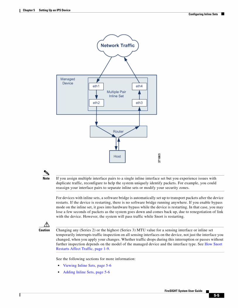
You can configure the interfaces on your managed device to route traffic between a host on your network and external hosts through different inline interface pairs, depending on whether the device traffic is inbound or outbound. This is an asynchronous routing configuration. If you deploy asynchronous routing but you include only one interface pair in an inline set, the device may not correctly analyze your network traffic because it might see only half of the traffic. Adding multiple inline interface pairs to the same inline interface set allows the system to identify the inbound and outbound traffic as part of the same traffic flow. You can also achieve this by including the interface pairs in the same security zone.
When the system generates a connection event from traffic passing through an asynchronous routing configuration, the event may identify an ingress and egress interface from the same inline interface pair. The configuration in the following diagram, for example, would generate a connection event identifying eth3 as the ingress interface and eth2 as the egress interface. This is expected behavior in this configuration.
5-4FireSIGHT System User Guide
Chapter 5 Setting Up an IPS Device Configuring Inline Sets
Note If you assign multiple interface pairs to a single inline interface set but you experience issues with duplicate traffic, reconfigure to help the system uniquely identify packets. For example, you could reassign your interface pairs to separate inline sets or modify your security zones.
For devices with inline sets, a software bridge is automatically set up to transport packets after the device restarts. If the device is restarting, there is no software bridge running anywhere. If you enable bypass mode on the inline set, it goes into hardware bypass while the device is restarting. In that case, you may lose a few seconds of packets as the system goes down and comes back up, due to renegotiation of link with the device. However, the system will pass traffic while Snort is restarting.
Caution Changing any (Series 2) or the highest (Series 3) MTU value for a sensing interface or inline set temporarily interrupts traffic inspection on all sensing interfaces on the device, not just the interface you changed, when you apply your changes. Whether traffic drops during this interruption or passes without further inspection depends on the model of the managed device and the interface type. See How Snort Restarts Affect Traffic, page 1-9.
See the following sections for more information:
• Viewing Inline Sets, page 5-6
• Adding Inline Sets, page 5-6
5-5FireSIGHT System User Guide
Chapter 5 Setting Up an IPS Device Configuring Inline Sets
• Configuring Advanced Inline Set Options, page 5-7
• Deleting Inline Sets, page 5-10
Viewing Inline SetsLicense: Protection
The Inline Sets tab of the Device Management page displays a list of all inline sets you have configured on a device. Note that you cannot configure inline sets to go into bypass mode on a virtual device or Cisco NGIPS for Blue Coat X-Series. The Inline Sets Table View Fields table includes summary information about each set.
Adding Inline SetsLicense: Protection
You can add inline sets from the Inline Sets tab of the Device Management page or you can add inline sets as you configure inline interfaces.
You can assign only inline interface pairs to an inline set. If you want to create an inline set before you configure the inline interfaces on your managed devices, you can create an empty inline set and add interfaces to it later.
To add an inline set:
Access: Admin/Network Admin
Step 1 Select Devices > Device Management.
The Device Management page appears.
Step 2 Next to the device where you want to add the inline set, click the edit icon ( ).
The Interfaces tab appears.
Step 3 Click Inline Sets.
The Inline Sets tab appears.
Step 4 Click Add Inline Set.
The Add Inline Set pop-up window appears.
Step 5 In the Name field, type a name for the inline set. You can use alphanumeric characters and spaces.
Step 6 You have two options for selecting inline interface pairs to add to the inline set:
• Next to Interfaces, select one or more inline interface pairs, then click the add selected icon ( ). Use Ctrl or Shift to select multiple inline interface pairs.
Table 5-1 Inline Sets Table View Fields
Field Description
Name The name of the inline set.
Interface Pairs A list of all pairs of inline interfaces assigned to the inline set. A pair is not available when you disable either interface in the pair from the Interfaces tab.
Bypass The configured bypass mode of the inline set.
5-6FireSIGHT System User Guide
Chapter 5 Setting Up an IPS Device Configuring Inline Sets
• To add all interface pairs to the inline set, click the add all icon ( ).
Tip To remove inline interfaces from the inline set, select one or more inline interface pairs and click the remove selected icon ( ). To remove all interface pairs from the inline set, click the remove all icon ( ). Disabling either interface in a pair from the Interfaces tab also removes the pair.
Step 7 In the MTU field, type a maximum transmission unit (MTU), which designates the largest size packet allowed.
The range within which you can set the MTU can vary depending on the FireSIGHT System device model and the interface type. See MTU Ranges for Managed Devices, page 4-64 for more information.
Step 8 Optionally, select Failsafe to specify that traffic is allowed to bypass detection and continue through the device. Managed devices monitor internal traffic buffers and bypass detection if those buffers are full.
Enabling Failsafe on a device with inline sets greatly decreases the risk of dropped packets if the internal traffic buffers are full, but your device may still drop packets in certain conditions. In the worst case, your device may experience a temporary network outage.
Note that only Series 3 devices support this option.
Step 9 Select the bypass mode to configure how the relays in the inline interfaces respond when an interface fails:
• Select Bypass to allow traffic to continue to pass through the interfaces.
• Select Non-Bypass to block traffic.
Note In bypass mode, you may lose a few packets when you reboot the appliance. Also note that you cannot configure bypass mode for inline sets on clustered devices, inline sets on a virtual device or Cisco NGIPS for Blue Coat X-Series, for non-bypass NetMods on 8000 Series devices, or for SFP modules on 3D7115 or 3D7125 devices.
Step 10 Click OK.
The inline set is added. Note that your changes do not take effect until you apply the device configuration; see Applying Changes to Devices, page 4-25 for more information.
Tip To configure advanced settings for the inline set, such as tap mode, link state propagation, and transparent inline mode, see Configuring Advanced Inline Set Options, page 5-7.
Configuring Advanced Inline Set OptionsLicense: Protection
Supported Devices: feature dependent
There are a number of options you may consider as you configure inline sets. See the sections below for more information about each option.
Tap Mode
Supported Devices: Series 3
5-7FireSIGHT System User Guide
Chapter 5 Setting Up an IPS Device Configuring Inline Sets
Tap mode is available on Series 3 devices when you create an inline or inline with fail-open interface set.
With tap mode, the device is deployed inline, but instead of the packet flow passing through the device, a copy of each packet is sent to the device and the network traffic flow is undisturbed. Because you are working with copies of packets rather than the packets themselves, rules that you set to drop and rules that use the replace keyword do not affect the packet stream. However, rules of these types do generate intrusion events when they are triggered, and the table view of intrusion events indicates that the triggering packets would have dropped in an inline deployment.
There are benefits to using tap mode with devices that are deployed inline. For example, you can set up the cabling between the device and the network as if the device were inline and analyze the kinds of intrusion events the device generates. Based on the results, you can modify your intrusion policy and add the drop rules that best protect your network without impacting its efficiency. When you are ready to deploy the device inline, you can disable tap mode and begin dropping suspicious traffic without having to reconfigure the cabling between the device and the network.
Note that you cannot enable this option and strict TCP enforcement on the same inline set.
Propagate Link State
Supported Devices: Series 2, Series 3
Link state propagation is a feature for inline sets configured in bypass mode so both pairs of an inline set track state. Link state propagation is available for both copper and fiber configurable bypass interfaces.
Link state propagation automatically brings down the second interface in the inline interface pair when one of the interfaces in an inline set goes down. When the downed interface comes back up, the second interface automatically comes back up, also. In other words, if the link state of one interface changes, the appliance senses the change and updates the link state of the other interface to match it. Note that appliances require up to 4 seconds to propagate link state changes.
Note When link state propagation triggers, fiber inline sets configured as fail-open on Series 2 devices activate hardware bypass mode. In this case, the interface cards involved do not come out of bypass automatically; you must bring them out of bypass mode manually. For more information about fiber interfaces in inline sets and hardware bypass, see Removing Bypass Mode on Fiber Inline Sets Configured to Fail Open, page 5-10.
Link state propagation is especially useful in resilient network environments where routers are configured to reroute traffic automatically around network devices that are in a failure state.
You cannot disable link state propagation for inline sets configured on clustered devices.
Note that virtual devices, Cisco NGIPS for Blue Coat X-Series, and Cisco ASA with FirePOWER Services do not support link state propagation.
Transparent Inline Mode
Transparent Inline Mode option allows the device to act as a “bump in the wire” and means that the device forwards all the network traffic it sees, regardless of its source and destination. Note that you cannot disable this option on Series 3 or 3D9900 devices.
Strict TCP Enforcement
Supported Devices: Series 3
To maximize TCP security, you can enable strict enforcement, which blocks connections where the three-way handshake was not completed. Strict enforcement also blocks:
5-8FireSIGHT System User Guide
Chapter 5 Setting Up an IPS Device Configuring Inline Sets
• non-SYN TCP packets for connections where the three-way handshake was not completed
• non-SYN/RST packets from the initiator on a TCP connection before the responder sends the SYN-ACK
• non-SYN-ACK/RST packets from the responder on a TCP connection after the SYN but before the session is established
• SYN packets on an established TCP connection from either the initiator or the responder
Note that Series 2, virtual devices, and Cisco NGIPS for Blue Coat X-Series do not support this option. In addition, you cannot enable this option and tap mode on the same inline set.
To configure advanced inline set options:
Access: Admin/Network Admin
Step 1 Select Devices > Device Management.
The Device Management page appears.
Step 2 Next to the device where you want to edit the inline set, click the edit icon ( ).
The Interfaces tab appears.
Step 3 Click Inline Sets.
The Inline Sets tab appears.
Step 4 Next to the inline set you want to edit, click the edit icon ( ).
The Edit Inline Set pop-up window appears.
Step 5 Click Advanced.
The Advanced tab appears.
Step 6 Optionally, select Tap Mode to enable tap mode on the inline interfaces of Series 3 devices.
Note that virtual devices, Cisco NGIPS for Blue Coat X-Series, and Series 2 devices other than 3D9900 do not support this option. In addition, you cannot enable Tap Mode and Strict TCP Enforcement on the same inline set.
Step 7 Optionally, select Propagate Link State on Series 2 or Series 3 devices. This option is especially useful if the routers on your network are able to reroute traffic around a network device that is down.
You cannot disable link state propagation for inline sets configured on clustered devices.
Note that virtual devices and Cisco NGIPS for Blue Coat X-Series do not support this option.
Step 8 Optionally, select Strict TCP Enforcement to enable strict TCP enforcement on Series 3 devices.
Note that Series 2, virtual devices, and Cisco NGIPS for Blue Coat X-Series do not support this option. In addition, you cannot enable Strict TCP Enforcement and Tap Mode on the same inline set.
Step 9 Optionally, select Transparent Inline Mode.
Note that you cannot disable this option on Series 3 devices.
Step 10 Click OK.
Your changes are saved. Note that your changes do not take effect until you apply the device configuration; see Applying Changes to Devices, page 4-25 for more information.
5-9FireSIGHT System User Guide
Chapter 5 Setting Up an IPS Device Configuring Inline Sets
Removing Bypass Mode on Fiber Inline Sets Configured to Fail Open
License: Protection
Supported Devices: Series 2
When link state propagation is enabled on a Series 2 device with a fiber inline set configured to fail open and the device goes into bypass mode, all network traffic passes through the inline set without being analyzed. When the links restore, most fiber inline sets configured to fail open do not return from bypass automatically. You can use a command line tool to force the inline set out of bypass mode.
This tool works on inline sets with fiber inline interfaces configured to fail open. It is not necessary to use this tool on inline sets with copper inline interfaces set to fail open.
Note Contact Support if you are having issues with inline sets configured to fail open on your device.
To force a fiber inline set configured to fail open out of bypass mode on a device:
Access: Admin/Network Admin
Step 1 Open a terminal window on your device and sign in as the admin user.
Step 2 Enter the following at the command line:
sudo /var/sf/bin/unbypass_cards.sh
You are prompted for your password.
Step 3 When the interfaces switch out of bypass mode, a message in syslog indicates the device is analyzing traffic. For example:
Fiber pair has been reset by un_bypass
Deleting Inline SetsLicense: Protection
When you delete an inline set, any inline interfaces assigned to the set become available for inclusion in another set. The interfaces are not deleted.
To delete an inline set:
Access: Admin/Network Admin
Step 1 Select Devices > Device Management.
The Device Management page appears.
Step 2 Next to the device where you want to delete the inline set, click the edit icon ( ).
The Interfaces tab appears.
Step 3 Click Inline Sets.
The Inline Sets tab appears.
Step 4 Next to the inline set you want to delete, click the delete icon ( ).
Step 5 When prompted, confirm that you want to delete the inline set.
5-10FireSIGHT System User Guide
Chapter 5 Setting Up an IPS Device Configuring Cisco NGIPS for Blue Coat X-Series Interfaces
The inline set is deleted. Note that your changes do not take effect until you apply the device configuration; see Applying Changes to Devices, page 4-25 for more information.
Configuring Cisco NGIPS for Blue Coat X-Series InterfacesLicense: Protection
Supported Devices: X-Series
You create passive or inline interfaces when you deploy Cisco NGIPS for Blue Coat X-Series package, or after the package has been installed. When you add Cisco NGIPS for Blue Coat X-Series to the Defense Center, these interfaces are already configured. Cisco NGIPS for Blue Coat X-Series does not support advanced configuration options.
You cannot reconfigure Cisco NGIPS for Blue Coat X-Series interfaces using the FireSIGHT System web interface. To reconfigure, you must first delete the current interface from the Defense Center, then create a new interface. For more information on creating and deleting interfaces, see the Cisco NGIPS for Blue Coat X-Series Installation Guide.
To configure an interface on Cisco NGIPS for Blue Coat X-Series:
Access: Admin/Network Admin
Step 1 Select Devices > Device Management.
The Device Management page appears.
Step 2 Next to the device you want to configure, click the edit icon ( ).
The Interfaces tab appears. Note that Link is always shown as active ( ) for all Cisco NGIPS for Blue Coat X-Series interfaces.
Step 3 Next to the interface you want to configure, click the edit icon ( ).
Step 4 From the Security Zone drop-down list, select an existing security zone or select New to add a new security zone.
Step 5 Optionally, for an inline interface, from the Inline Set drop-down list, select an existing inline set or select New to add a new inline set.
Note that if you add a new inline set, you must configure it on the Device Management page (Devices > Device Management > Inline Sets) after you set up the inline interface. For more information, see Adding Inline Sets, page 5-6.
Step 6 Click Save.
The interface is configured. Note that your changes do not take effect until you apply the device configurations by clicking Apply Changes at top right of the menu bar.
5-11FireSIGHT System User Guide

Chapter 5 Setting Up an IPS Device Configuring Cisco NGIPS for Blue Coat X-Series Interfaces
5-12FireSIGHT System User Guide