Embed Size (px)
Citation preview
CNT-SVX05B-EN
Setup and Operation
Tracer™ AH540/541 Version 2
Air-Handler Controller

Setup and Operation
Tracer™ AH540/541 Version 2
Air-Handler Controller
CNT-SVX05B-EN
April 2004

CNT-SVX05B-EN
Tracer AH540/541 Version 2 Air-Handler Controller Setup and Operation
This guide and the information in it are the property of American Standard Inc. and may not be used or reproduced in whole or in part, without the written permission of American Standard Inc. Trane, a business of American Standard, Inc., has a policy of continuous product and product data improvement and reserves the right to change design and specification without notice.
Although Trane has tested the hardware and software described in this guide, no guarantee is offered that the hardware and software are error free.
Trane reserves the right to revise this publication at any time and to make changes to its content without obligation to notify any per-son of such revision or change.
Trane may have patents or patent applications covering items in this publication. By providing this document, Trane does not imply giving license to these patents.
The following are trademarks or registered trademarks of American Standard Inc.: Climate Changer, Rover, Tracer, Tracer Summit, Trane.
The following are trademarks or registered trademarks of their respective companies or organizations: LonMark from Echelon Corporation.
Printed in the U.S.A.
© 2004 American Standard Inc. All rights reserved.
™ ®
™ ®
CNT-SVX05B-EN
NOTICE:Warnings and Cautions appear at appropriate sections throughout this manual. Read these carefully:
WARNINGIndicates a potentially hazardous situation, which, if not avoided, could result in death or serious injury.
CAUTIONIndicates a potentially hazardous situation, which, if not avoided, may result in minor or moderate injury.
It may also be used to alert against unsafe practices.
CAUTIONIndicates a situation that may result in equipment damage or property damage.
The following format and symbol conventions appear at appropriate sections throughout this manual:
IMPORTANTAlerts installer, servicer, or operator to potential actions that could cause the product or system to
operate improperly but will not likely result in potential for damage.
This symbol precedes a procedure that consists of only a single step.
Note:
A note may be used to make the reader aware of useful information, to clarify a point, or to describe options or alternatives.
CNT-SVX05B-EN
Contents
Chapter 1 Overview and specifications . . . . . . . . . . . . . . . . . . 1
Configuration options . . . . . . . . . . . . . . . . . . . . . . . . . . . . . . . . . . . . . . . . 1
Communication with other controllers. . . . . . . . . . . . . . . . . . . . . . . . . . . 3
Controller circuit boards . . . . . . . . . . . . . . . . . . . . . . . . . . . . . . . . . . . 4
Specifications . . . . . . . . . . . . . . . . . . . . . . . . . . . . . . . . . . . . . . . . . . . . . . . 7
Chapter 2 Operator display. . . . . . . . . . . . . . . . . . . . . . . . . . . . 9
Installing the stand-alone operator display . . . . . . . . . . . . . . . . . . . . . . . 9
Connecting the portable operator display . . . . . . . . . . . . . . . . . . . . . . . .11
Setting up the operator display . . . . . . . . . . . . . . . . . . . . . . . . . . . . . . . . 12
Setting up time and date . . . . . . . . . . . . . . . . . . . . . . . . . . . . . . . . . . 12
Calibrating the operator display . . . . . . . . . . . . . . . . . . . . . . . . . . . . 13
Adjusting brightness and contrast . . . . . . . . . . . . . . . . . . . . . . . . . . 13
Setting up, changing, or disabling the security password . . . . . . . 14
Chapter 3 Input and Outputs . . . . . . . . . . . . . . . . . . . . . . . . . 15
Binary outputs. . . . . . . . . . . . . . . . . . . . . . . . . . . . . . . . . . . . . . . . . . . . . . 15
Analog outputs . . . . . . . . . . . . . . . . . . . . . . . . . . . . . . . . . . . . . . . . . . . . . 16
Analog inputs . . . . . . . . . . . . . . . . . . . . . . . . . . . . . . . . . . . . . . . . . . . . . . 17
IN1: Space temperature . . . . . . . . . . . . . . . . . . . . . . . . . . . . . . . . . . . 18
IN2: Local setpoint . . . . . . . . . . . . . . . . . . . . . . . . . . . . . . . . . . . . . . . 18
IN3: Fan mode switch. . . . . . . . . . . . . . . . . . . . . . . . . . . . . . . . . . . . . 19
IN4: Discharge air temperature . . . . . . . . . . . . . . . . . . . . . . . . . . . . . 19
IN5: Outdoor air temperature . . . . . . . . . . . . . . . . . . . . . . . . . . . . . . 19
IN6: Mixed-air temperature . . . . . . . . . . . . . . . . . . . . . . . . . . . . . . . . 20
IN13: Universal analog input. . . . . . . . . . . . . . . . . . . . . . . . . . . . . . . 20
J43: Duct static pressure . . . . . . . . . . . . . . . . . . . . . . . . . . . . . . . . . . 22
on/cancel buttons on the zone sensor . . . . . . . . . . . . . . . . . . . . . . . 23
Binary inputs . . . . . . . . . . . . . . . . . . . . . . . . . . . . . . . . . . . . . . . . . . . . . . . 23
IN7: Low-temperature detection or coil defrost . . . . . . . . . . . . . . . 24
IN8: Run/stop . . . . . . . . . . . . . . . . . . . . . . . . . . . . . . . . . . . . . . . . . . . 25
IN9: Occupancy or generic . . . . . . . . . . . . . . . . . . . . . . . . . . . . . . . . 25
IN10: Supply fan status . . . . . . . . . . . . . . . . . . . . . . . . . . . . . . . . . . . 26
IN11: Filter status . . . . . . . . . . . . . . . . . . . . . . . . . . . . . . . . . . . . . . . . 26
IN12: Exhaust fan status or coil defrost . . . . . . . . . . . . . . . . . . . . . . 27
CNT-SVX05B-EN i
Contents
Zone sensors . . . . . . . . . . . . . . . . . . . . . . . . . . . . . . . . . . . . . . . . . . . . . . . 28
Space temperature measurement. . . . . . . . . . . . . . . . . . . . . . . . . . . 28
Zone sensor setpoint thumbwheel . . . . . . . . . . . . . . . . . . . . . . . . . . 28
Fan mode switch . . . . . . . . . . . . . . . . . . . . . . . . . . . . . . . . . . . . . . . . . 28
on/cancel buttons . . . . . . . . . . . . . . . . . . . . . . . . . . . . . . . . . . . . . . . . 29
Zone sensor communication jack . . . . . . . . . . . . . . . . . . . . . . . . . . . 29
Service Pin message request. . . . . . . . . . . . . . . . . . . . . . . . . . . . . . . 29
Zone sensor wiring connections . . . . . . . . . . . . . . . . . . . . . . . . . . . . 29
Chapter 4 Sequence of operation . . . . . . . . . . . . . . . . . . . . . 31
Control modes . . . . . . . . . . . . . . . . . . . . . . . . . . . . . . . . . . . . . . . . . . . . . . 31
Space temperature control . . . . . . . . . . . . . . . . . . . . . . . . . . . . . . . . . . . 31
Control gains . . . . . . . . . . . . . . . . . . . . . . . . . . . . . . . . . . . . . . . . . . . . 32
Heating/cooling mode control . . . . . . . . . . . . . . . . . . . . . . . . . . . . . 32
Cooling operation . . . . . . . . . . . . . . . . . . . . . . . . . . . . . . . . . . . . . . . . 35
Heating operation . . . . . . . . . . . . . . . . . . . . . . . . . . . . . . . . . . . . . . . . 36
Space temperature setpoint arbitration . . . . . . . . . . . . . . . . . . . . . . 36
Discharge air temperature control . . . . . . . . . . . . . . . . . . . . . . . . . . . . . 38
Heating/cooling mode control . . . . . . . . . . . . . . . . . . . . . . . . . . . . . . 39
Power-up sequence . . . . . . . . . . . . . . . . . . . . . . . . . . . . . . . . . . . . . . . . . . 40
Occupancy modes . . . . . . . . . . . . . . . . . . . . . . . . . . . . . . . . . . . . . . . . . . 41
Occupied mode. . . . . . . . . . . . . . . . . . . . . . . . . . . . . . . . . . . . . . . . . . 41
Unoccupied mode. . . . . . . . . . . . . . . . . . . . . . . . . . . . . . . . . . . . . . . . 41
Occupied standby mode . . . . . . . . . . . . . . . . . . . . . . . . . . . . . . . . . . 42
Occupied bypass mode . . . . . . . . . . . . . . . . . . . . . . . . . . . . . . . . . . . 43
Sources of occupancy mode control . . . . . . . . . . . . . . . . . . . . . . . . 43
Determining the occupancy mode . . . . . . . . . . . . . . . . . . . . . . . . . . 44
Timed override control . . . . . . . . . . . . . . . . . . . . . . . . . . . . . . . . . . . . . . 47
Morning warm-up . . . . . . . . . . . . . . . . . . . . . . . . . . . . . . . . . . . . . . . . . . . 47
Space temperature control: Morning warm-up . . . . . . . . . . . . . . . 47
Discharge air temperature control: Morning warm-up . . . . . . . . . . 48
Daytime warm-up . . . . . . . . . . . . . . . . . . . . . . . . . . . . . . . . . . . . . . . . . . . 48
Cool-down . . . . . . . . . . . . . . . . . . . . . . . . . . . . . . . . . . . . . . . . . . . . . . . . . 49
Space temperature control: Cool-down . . . . . . . . . . . . . . . . . . . . . . 49
Discharge air temperature control: Cool-down . . . . . . . . . . . . . . . . 49
Supply fan operation . . . . . . . . . . . . . . . . . . . . . . . . . . . . . . . . . . . . . . . . 50
Constant-volume supply fan operation . . . . . . . . . . . . . . . . . . . . . . 50
Variable-air-volume supply fan operation: Duct static pressure . . . 51
Valve operation . . . . . . . . . . . . . . . . . . . . . . . . . . . . . . . . . . . . . . . . . . . . . 52
Freeze-avoidance valve cycling . . . . . . . . . . . . . . . . . . . . . . . . . . . . 52
ii CNT-SVX05B-EN
Contents
Two-pipe changeover . . . . . . . . . . . . . . . . . . . . . . . . . . . . . . . . . . . . . . . . 53
Entering water temperature sampling . . . . . . . . . . . . . . . . . . . . . . . . . . 53
Three-way valve applications . . . . . . . . . . . . . . . . . . . . . . . . . . . . . . 53
Two-way valve applications . . . . . . . . . . . . . . . . . . . . . . . . . . . . . . . 54
Face-and-bypass damper operation . . . . . . . . . . . . . . . . . . . . . . . . . . . . 55
Outdoor air damper operation . . . . . . . . . . . . . . . . . . . . . . . . . . . . . . . . 56
Mixed-air temperature control . . . . . . . . . . . . . . . . . . . . . . . . . . . . . 57
Economizing . . . . . . . . . . . . . . . . . . . . . . . . . . . . . . . . . . . . . . . . . . . . . . . 58
Low ambient damper lockout . . . . . . . . . . . . . . . . . . . . . . . . . . . . . . 59
Exhaust fan operation . . . . . . . . . . . . . . . . . . . . . . . . . . . . . . . . . . . . . . . 59
Electric heat operation . . . . . . . . . . . . . . . . . . . . . . . . . . . . . . . . . . . . . . . 60
Space temperature control: Electric heat . . . . . . . . . . . . . . . . . . . . . 61
Discharge air temperature control: Electric heat . . . . . . . . . . . . . . . 61
Staged electric heat . . . . . . . . . . . . . . . . . . . . . . . . . . . . . . . . . . . . . . 61
DX cooling operation . . . . . . . . . . . . . . . . . . . . . . . . . . . . . . . . . . . . . . . . 64
Staged DX cooling . . . . . . . . . . . . . . . . . . . . . . . . . . . . . . . . . . . . . . 65
Defrost operation . . . . . . . . . . . . . . . . . . . . . . . . . . . . . . . . . . . . . . . . 65
DX split-system cooling. . . . . . . . . . . . . . . . . . . . . . . . . . . . . . . . . . . 66
Dehumidification . . . . . . . . . . . . . . . . . . . . . . . . . . . . . . . . . . . . . . . . . . . 68
Occupied and unoccupied mode dehumidification . . . . . . . . . . . . 68
Unit protection strategies . . . . . . . . . . . . . . . . . . . . . . . . . . . . . . . . . . . . 70
Filter status . . . . . . . . . . . . . . . . . . . . . . . . . . . . . . . . . . . . . . . . . . . . . 70
Freeze avoidance . . . . . . . . . . . . . . . . . . . . . . . . . . . . . . . . . . . . . . . . 70
Overrides . . . . . . . . . . . . . . . . . . . . . . . . . . . . . . . . . . . . . . . . . . . . . . . . . . 71
Manual output test . . . . . . . . . . . . . . . . . . . . . . . . . . . . . . . . . . . . . . . 71
Emergency override. . . . . . . . . . . . . . . . . . . . . . . . . . . . . . . . . . . . . . 71
Water valve override . . . . . . . . . . . . . . . . . . . . . . . . . . . . . . . . . . . . . 72
Chapter 5 Configuration . . . . . . . . . . . . . . . . . . . . . . . . . . . . . 73
Chapter 6 Verifying operation and communication . . . . . . . 83
Test button. . . . . . . . . . . . . . . . . . . . . . . . . . . . . . . . . . . . . . . . . . . . . . . . . 83
Performing a manual output test . . . . . . . . . . . . . . . . . . . . . . . . . . . . . . 84
Service Pin button. . . . . . . . . . . . . . . . . . . . . . . . . . . . . . . . . . . . . . . . . . . 86
Interpreting LEDs . . . . . . . . . . . . . . . . . . . . . . . . . . . . . . . . . . . . . . . . . . . 86
Binary output LEDs (green) . . . . . . . . . . . . . . . . . . . . . . . . . . . . . . . . 86
Service LED (red) . . . . . . . . . . . . . . . . . . . . . . . . . . . . . . . . . . . . . . . . 87
Status LED (green) . . . . . . . . . . . . . . . . . . . . . . . . . . . . . . . . . . . . . . . 87
Comm LED (yellow) . . . . . . . . . . . . . . . . . . . . . . . . . . . . . . . . . . . . . 88
CNT-SVX05B-EN iii
Contents
Required inputs for unit operation . . . . . . . . . . . . . . . . . . . . . . . . . . . . . 88
Diagnostics . . . . . . . . . . . . . . . . . . . . . . . . . . . . . . . . . . . . . . . . . . . . . . . . 89
Resetting diagnostics . . . . . . . . . . . . . . . . . . . . . . . . . . . . . . . . . . . . . 89
Interpreting multiple diagnostics . . . . . . . . . . . . . . . . . . . . . . . . . . . 90
Chapter 7 Troubleshooting . . . . . . . . . . . . . . . . . . . . . . . . . . . . 9
Appendix . . . . . . . . . . . . . . . . . . . . . . . . . . . . . . . . . . . . . . . . .101
Unit operation based on heat/cool mode . . . . . . . . . . . . . . . . . . . . . . . 101
Entering water temperature sampling. . . . . . . . . . . . . . . . . . . . . . . . . . 105
Input sensor tables . . . . . . . . . . . . . . . . . . . . . . . . . . . . . . . . . . . . . . . 106
AH540/541 network variables. . . . . . . . . . . . . . . . . . . . . . . . . . . . . . . . . 109
Index . . . . . . . . . . . . . . . . . . . . . . . . . . . . . . . . . . . . . . . . 115
Reader Response
Form . . . . . . . . . . . . . . . . . . . . . . . . . . . . . . . . . . . . . . . 121
iv CNT-SVX05B-EN
Chapter 1
Overview and specifications
The Tracer™ AH540 and the Tracer AH541 air-handler controllers pro-vide digital control for a variety of constant-volume and variable-air-vol-ume (VAV) air-handling units that conform to the LonMark® Space Comfort Controller (SCC) profile or the Discharge Air Controller (DAC) profile. The Tracer AH541 is available in several models for field installa-tion (BAS-PRC013-EN describes them). The Tracer AH540 controller is available installed, pre-wired, and tested with the following Trane air-handling units:
• Packaged Climate Changer™ air-handling unit• M-Series Climate Changer air-handling unit• T-Series Climate Changer air-handling unit
The functionality of the factory-installed Tracer AH540 controller is iden-tical to that of the field-installed Tracer AH541 controller. This document refers to both versions of the controller as “the Tracer AH540/541” or “the controller” unless a distinction needs to be made between the two.
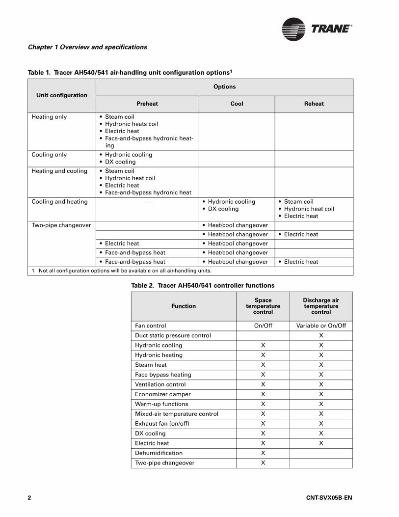
Configuration optionsAir-handling unit configurations supported by the Tracer AH540/541 are shown in Table 1 on page 2. Functionality options are shown in Table 2 on page 2.
Note:
This manual applies to Version 2 of the Tracer AH540/541 con-troller. Both hardware and functional differences exist between Version 1 and Version 2. Version 2 hardware has four additional binary outputs and a universal analog input. These hardware additions support Version 2 functions, which include all of those inVersion 1 plus DX cooling, electric heat, dehumidification, and two-pipe changeover.
CNT-SVX05B-EN 1
Chapter 1 Overview and specifications
Table 1. Tracer AH540/541 air-handling unit configuration options1
Unit configuration
Options
Preheat Cool Reheat
Heating only • Steam coil• Hydronic heats coil• Electric heat• Face-and-bypass hydronic heat-
ing
Cooling only • Hydronic cooling• DX cooling
Heating and cooling • Steam coil• Hydronic heat coil• Electric heat• Face-and-bypass hydronic heat
Cooling and heating — • Hydronic cooling• DX cooling
• Steam coil• Hydronic heat coil• Electric heat
Two-pipe changeover • Heat/cool changeover
• Heat/cool changeover • Electric heat
• Electric heat • Heat/cool changeover
• Face-and-bypass heat • Heat/cool changeover
• Face-and-bypass heat • Heat/cool changeover • Electric heat1 Not all configuration options will be available on all air-handling units.
Table 2. Tracer AH540/541 controller functions
FunctionSpace
temperature control
Discharge air temperature
control
Fan control On/Off Variable or On/Off
Duct static pressure control X
Hydronic cooling X X
Hydronic heating X X
Steam heat X X
Face bypass heating X X
Ventilation control X X
Economizer damper X X
Warm-up functions X X
Mixed-air temperature control X X
Exhaust fan (on/off) X X
DX cooling X X
Electric heat X X
Dehumidification X
Two-pipe changeover X
2 CNT-SVX05B-EN
Communication with other controllers
Communication with other controllersTracer AH540/541 controllers operates either in stand-alone mode or as part of a building automation system. In either mode of operation, multi-ple controllers can be bound (bindings are configured using the Rover ser-vice tool) to other LonTalk®-based controllers so they can communicate data to one another. Controllers that are bound as peers can share the fol-lowing data:
• Setpoint• Zone temperature• Zone relative humidity• Outdoor air temperature• Occupancy mode• Heating/cooling mode• Fan status• Unit capacity control
Applications having more than one unit serving a single space can benefit by using this feature; it allows multiple units to share a single space tem-perature sensor and prevents multiple units from simultaneously heating and cooling. For more information, see “AH540/541 network variables” on page 109.
CNT-SVX05B-EN 3
Chapter 1 Overview and specifications
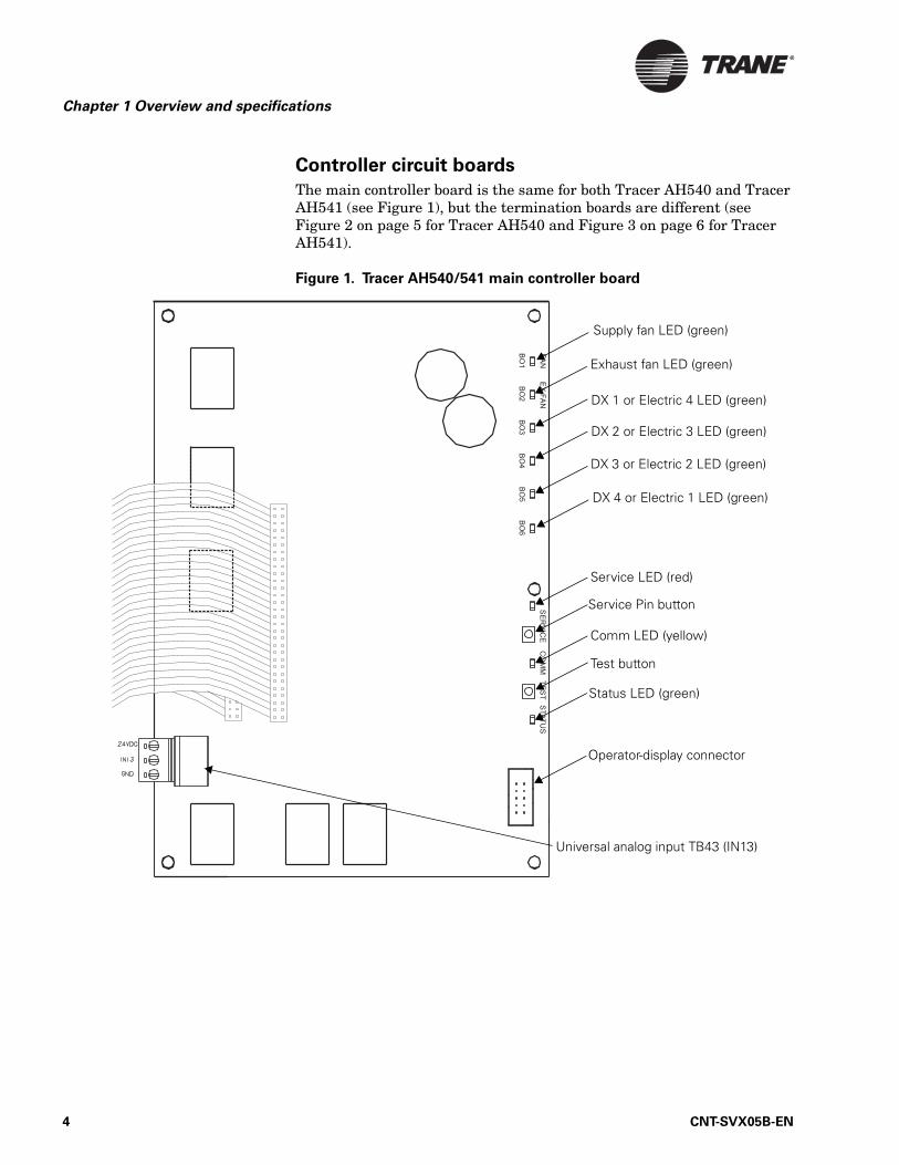
Controller circuit boards
The main controller board is the same for both Tracer AH540 and Tracer AH541 (see Figure 1), but the termination boards are different (see Figure 2 on page 5 for Tracer AH540 and Figure 3 on page 6 for Tracer AH541).
Figure 1. Tracer AH540/541 main controller board
Operator-display connector
Supply fan LED (green)
Exhaust fan LED (green)
Service Pin button
Comm LED (yellow)
Status LED (green)
Test button
DX 1 or Electric 4 LED (green)
DX 2 or Electric 3 LED (green)
DX 4 or Electric 1 LED (green)
Service LED (red)
Universal analog input TB43 (IN13)
DX 3 or Electric 2 LED (green)
4 CNT-SVX05B-EN
Communication with other controllers
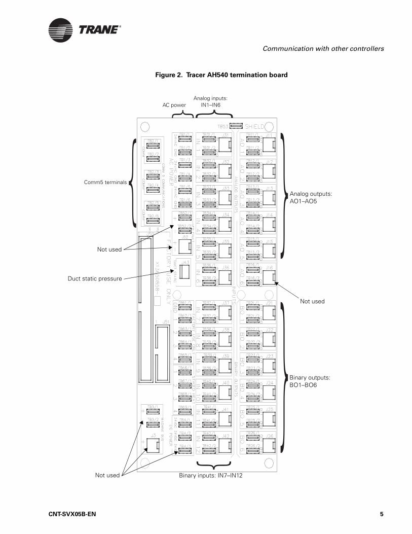
Figure 2. Tracer AH540 termination board
Analog outputs:AO1–AO5
Binary inputs: IN7–IN12
Binary outputs:BO1–BO6
Not used
Not used
Not used
AC powerAnalog inputs:
IN1–IN6
Duct static pressure
Comm5 terminals
CNT-SVX05B-EN 5
Chapter 1 Overview and specifications
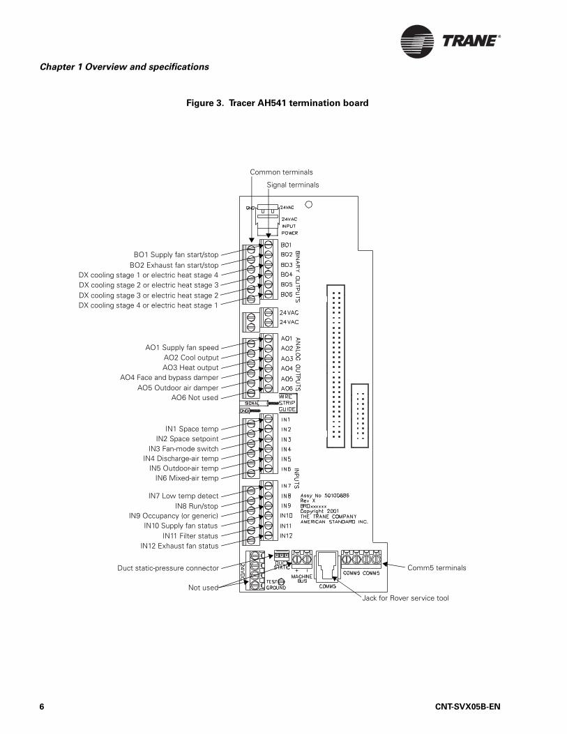
Figure 3. Tracer AH541 termination board
Common terminals
Signal terminals
Comm5 terminals
Jack for Rover service tool
Duct static-pressure connector
BO1 Supply fan start/stopBO2 Exhaust fan start/stop
AO1 Supply fan speedAO2 Cool outputAO3 Heat output
AO4 Face and bypass damperAO5 Outdoor air damper
IN1 Space tempIN2 Space setpoint
IN3 Fan-mode switchIN4 Discharge-air temp
IN5 Outdoor-air temp
IN7 Low temp detect
IN6 Mixed-air temp
IN8 Run/stopIN9 Occupancy (or generic)
IN10 Supply fan statusIN11 Filter status
IN12 Exhaust fan status
DX cooling stage 1 or electric heat stage 4DX cooling stage 2 or electric heat stage 3DX cooling stage 3 or electric heat stage 2DX cooling stage 4 or electric heat stage 1
AO6 Not used
Not used
6 CNT-SVX05B-EN
Specifications
Specifications
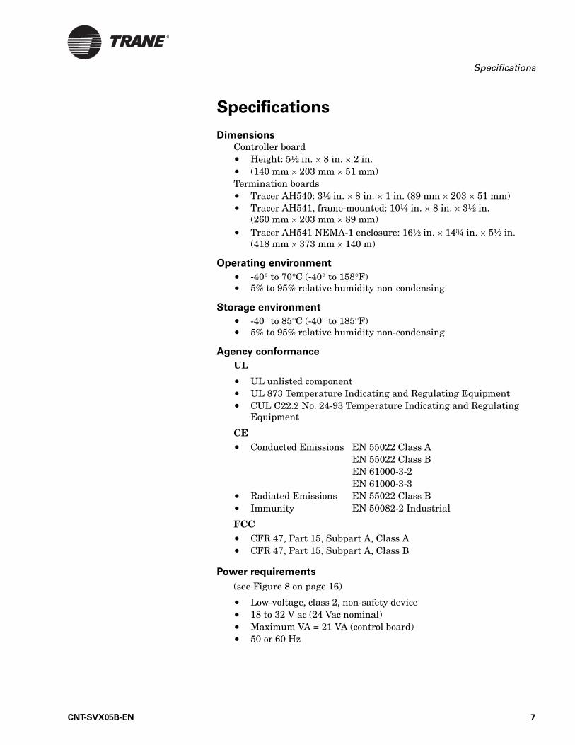
Dimensions Controller board• Height: 5½ in. × 8 in. × 2 in. • (140 mm × 203 mm × 51 mm)Termination boards• Tracer AH540: 3½ in. × 8 in. × 1 in. (89 mm × 203 × 51 mm)• Tracer AH541, frame-mounted: 10¼ in. × 8 in. × 3½ in.
(260 mm × 203 mm × 89 mm)• Tracer AH541 NEMA-1 enclosure: 16½ in. × 14¾ in. × 5½ in.
(418 mm × 373 mm × 140 m)
Operating environment
• -40° to 70°C (-40° to 158°F)• 5% to 95% relative humidity non-condensing
Storage environment
• -40° to 85°C (-40° to 185°F)• 5% to 95% relative humidity non-condensing
Agency conformance
UL
• UL unlisted component• UL 873 Temperature Indicating and Regulating Equipment• CUL C22.2 No. 24-93 Temperature Indicating and Regulating
Equipment
CE • Conducted Emissions EN 55022 Class A
EN 55022 Class BEN 61000-3-2EN 61000-3-3
• Radiated Emissions EN 55022 Class B• Immunity EN 50082-2 Industrial
FCC • CFR 47, Part 15, Subpart A, Class A• CFR 47, Part 15, Subpart A, Class B
Power requirements
(see Figure 8 on page 16)
• Low-voltage, class 2, non-safety device• 18 to 32 V ac (24 Vac nominal)• Maximum VA = 21 VA (control board) • 50 or 60 Hz
CNT-SVX05B-EN 7
Chapter 1 Overview and specifications
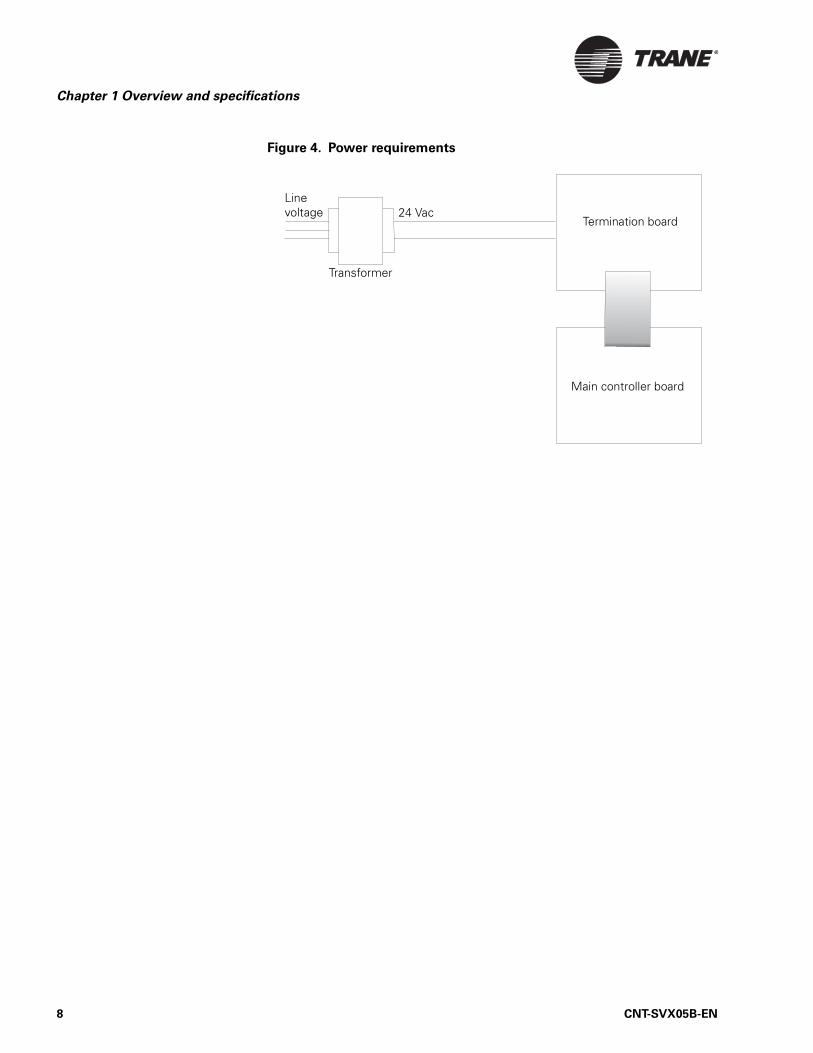
Figure 4. Power requirements
Termination board
Main controller board
Transformer
Line voltage 24 Vac
8 CNT-SVX05B-EN
Chapter 2
Operator display
This chapter shows how to:
• Install a Tracer AH540/541 stand-alone operator display• Connect a portable operator display to a Tracer AH540/541 controller• Set up the operator display
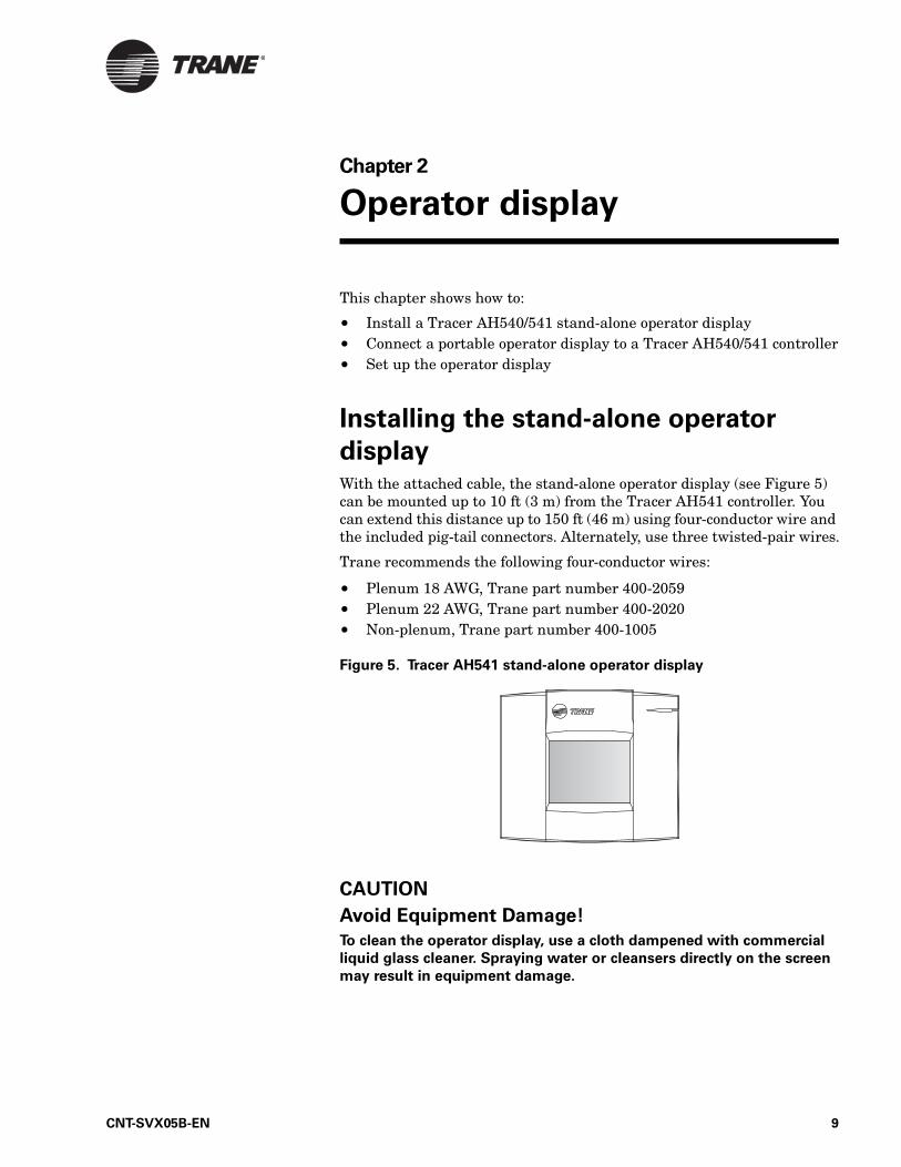
Installing the stand-alone operator
displayWith the attached cable, the stand-alone operator display (see Figure 5) can be mounted up to 10 ft (3 m) from the Tracer AH541 controller. You can extend this distance up to 150 ft (46 m) using four-conductor wire and the included pig-tail connectors. Alternately, use three twisted-pair wires.
Trane recommends the following four-conductor wires:
• Plenum 18 AWG, Trane part number 400-2059• Plenum 22 AWG, Trane part number 400-2020• Non-plenum, Trane part number 400-1005
Figure 5. Tracer AH541 stand-alone operator display
CAUTION
Avoid Equipment Damage!
To clean the operator display, use a cloth dampened with commercial
liquid glass cleaner. Spraying water or cleansers directly on the screen
may result in equipment damage.
CNT-SVX05B-EN 9
Chapter 2 Operator display
To install the stand-alone operator display:
1. Unsnap the gray plastic backing from the operator display.
2. Carefully disconnect the operator-display cable from the connector inside the operator display.
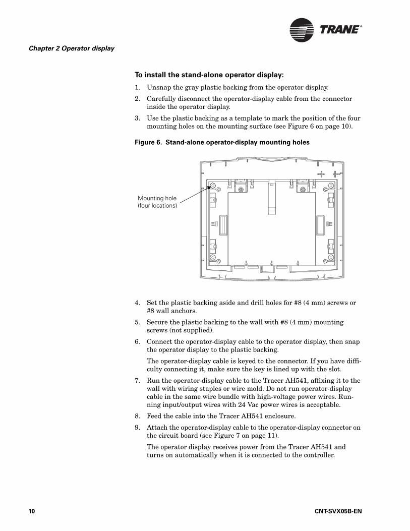
3. Use the plastic backing as a template to mark the position of the four mounting holes on the mounting surface (see Figure 6 on page 10).
Figure 6. Stand-alone operator-display mounting holes
4. Set the plastic backing aside and drill holes for #8 (4 mm) screws or #8 wall anchors.
5. Secure the plastic backing to the wall with #8 (4 mm) mounting screws (not supplied).
6. Connect the operator-display cable to the operator display, then snap the operator display to the plastic backing.
The operator-display cable is keyed to the connector. If you have diffi-culty connecting it, make sure the key is lined up with the slot.
7. Run the operator-display cable to the Tracer AH541, affixing it to the wall with wiring staples or wire mold. Do not run operator-display cable in the same wire bundle with high-voltage power wires. Run-ning input/output wires with 24 Vac power wires is acceptable.
8. Feed the cable into the Tracer AH541 enclosure.
9. Attach the operator-display cable to the operator-display connector on the circuit board (see Figure 7 on page 11).
The operator display receives power from the Tracer AH541 and turns on automatically when it is connected to the controller.
Mounting hole (four locations)
10 CNT-SVX05B-EN
Connecting the portable operator display
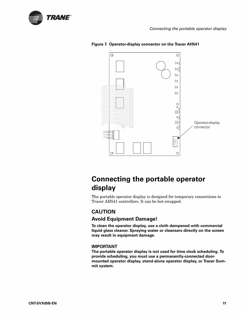
Figure 7. Operator-display connector on the Tracer AH541
Connecting the portable operator
displayThe portable operator display is designed for temporary connections to Tracer AH541 controllers. It can be hot-swapped.
CAUTION
Avoid Equipment Damage!
To clean the operator display, use a cloth dampened with commercial
liquid glass cleaner. Spraying water or cleansers directly on the screen
may result in equipment damage.
IMPORTANTThe portable operator display is not used for time clock scheduling. To
provide scheduling, you must use a permanently-connected door-
mounted operator display, stand-alone operator display, or Tracer Sum-
mit system.
Operator-display connector
CNT-SVX05B-EN 11
Chapter 2 Operator display
To connect the portable operator display:
1. Open the Tracer AH541 enclosure door.
2. Attach the operator-display cable to the operator-display connector on the circuit board (see Figure 7 on page 11).
The operator display receives power from the Tracer AH541 and turns on automatically when it is connected to the controller. The operator display is hot-swappable, so there is no need to power down the controller.
Setting up the operator displayThe home screen is the starting point for navigating through the screens of the operator display. The home screen is displayed when the unit is idle. The screen contains the following information from top to bottom:
• Time and date• The controller location label: When no location is specified and the
controller is a Tracer AH540, “Tracer AH540” is displayed. When no location is specified and the controller is a Tracer AH541, “Warning: Unit Config Required” is displayed.
• Operating parameters of the controller• Push buttons: Touch one of the five buttons—View, Alarm, Schedule,
Override, or Setup—to access the desired set of screens.
Setting up time and date
To change the time for the operator display:
1. On the home screen, press the Setup button. The Setup menu appears.
2. Press the down arrow button to go to Page 2 of 2.
3. Press the Change Time button to view the next screen.
4. Using the buttons, type the time using the format hh:mm, where hh is the hour and mm is the minute. Press either the AM or PM button, as appropriate.
5. To correct an error, press clear and start again. To accept the changes, press the OK button.
To change the date for the operator display:
1. On the home screen, press the Setup button. The Setup menu appears.
Note:
The schedule button does not appear on the Home screen when a portable operator display is connected to the controller because the portable operator display does not have a time clock and therefore cannot be used to set up schedules.
12 CNT-SVX05B-EN
Setting up the operator display
2. Press the down arrow button to go to page 2 of 2.
3. Press the Change Date button to view the next screen.
4. Press the forward and back arrows to move the cursor from day to month to year. Use the buttons to type the appropriate date.
5. To correct an error, press the reset button. To accept the changes, press the OK button.
Calibrating the operator display
To calibrate the operator display:
1. On the home screen, press the Setup button. The Setup menu appears.
2. Press the page down button to go to Page 2 of 2.
3. Press the Display Setup button. The Display Setup menu appears.
4. Press the Calibrate Touch Screen button. A screen with a target appears.
CAUTION
Avoid Equipment Damage!
Do not allow the operator display to come in contact with sharp objects.
5. Touch the target using a small, pliable, blunt object, such as a pencil eraser. Hold until the beeping stops. A second calibration screen appears.
6. Again, touch the target with the object. Hold until the beeping stops. The Setup menu appears.
7. Press the Home button. The home screen appears.
Adjusting brightness and contrast
To adjust the brightness and contrast of the operator display:
1. On the home screen, press the Setup button. The Setup menu appears.
2. Press the page down button to go to Page 2 of 2.
3. Press the Display Setup button. The Display Setup menu appears.
4. Press the Adjust Brightness and Contrast button. The Brightness and Contrast screen appears.
5. To increase the brightness, press the buttons along the top row, in sequence, from left to right. To decrease the brightness, press the buttons from right to left.
CNT-SVX05B-EN 13
Chapter 2 Operator display
6. To increase the contrast, press the buttons along the bottom row, in sequence, from left to right. To decrease the contrast, press the buttons from right to left.
7. Press the Home button. The home screen appears.
Setting up, changing, or disabling the security
password
To set up or change a security password or to disable its use:
1. On the home screen, press the Setup button. The Setup menu appears.
2. Press the page down button to go to page 2 of 2.
3. Press the Display Setup button. The Display Setup menu appears.
4. Press the page down button to go to page 2 of 2.
5. Press the Setup Security Password button. The Setup Security Pass-word screen appears.
6. To set up or change the password, use the number keys to enter 4 to 8 numbers. Press OK. Security is enabled.
Note:
If security is enabled, the logon screen will display whenever you try to change a value that is security protected. To log on, type the password using the numeric type pad. You will remain logged on while you continue to work. After 20 minutes, the sys-tem will log you off.
Note:
If a password was previously set up, a Disable Security button appears on the Setup Security Password screen. Press the Dis-able Security button to disable security.
14 CNT-SVX05B-EN
Chapter 3
Input and Outputs
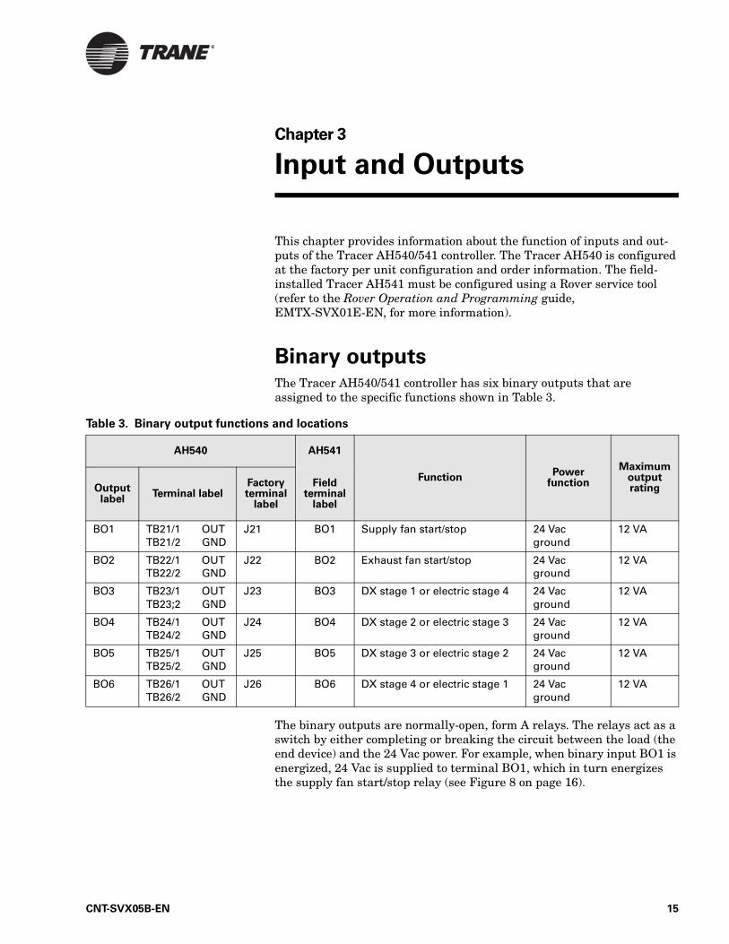
This chapter provides information about the function of inputs and out-puts of the Tracer AH540/541 controller. The Tracer AH540 is configured at the factory per unit configuration and order information. The field-installed Tracer AH541 must be configured using a Rover service tool (refer to the Rover Operation and Programming guide, EMTX-SVX01E-EN, for more information).
Binary outputsThe Tracer AH540/541 controller has six binary outputs that are assigned to the specific functions shown in Table 3.
The binary outputs are normally-open, form A relays. The relays act as a switch by either completing or breaking the circuit between the load (the end device) and the 24 Vac power. For example, when binary input BO1 is energized, 24 Vac is supplied to terminal BO1, which in turn energizes the supply fan start/stop relay (see Figure 8 on page 16).
Table 3. Binary output functions and locations
AH540 AH541
FunctionPower
function
Maximum output ratingOutput
labelTerminal label
Factoryterminal
label
Field terminal
label
BO1 TB21/1 OUTTB21/2 GND
J21 BO1 Supply fan start/stop 24 Vac ground
12 VA
BO2 TB22/1 OUTTB22/2 GND
J22 BO2 Exhaust fan start/stop 24 Vac ground
12 VA
BO3 TB23/1 OUTTB23;2 GND
J23 BO3 DX stage 1 or electric stage 4 24 Vac ground
12 VA
BO4 TB24/1 OUTTB24/2 GND
J24 BO4 DX stage 2 or electric stage 3 24 Vac ground
12 VA
BO5 TB25/1 OUTTB25/2 GND
J25 BO5 DX stage 3 or electric stage 2 24 Vac ground
12 VA
BO6 TB26/1 OUTTB26/2 GND
J26 BO6 DX stage 4 or electric stage 1 24 Vac ground
12 VA
CNT-SVX05B-EN 15
Chapter 3 Input and Outputs
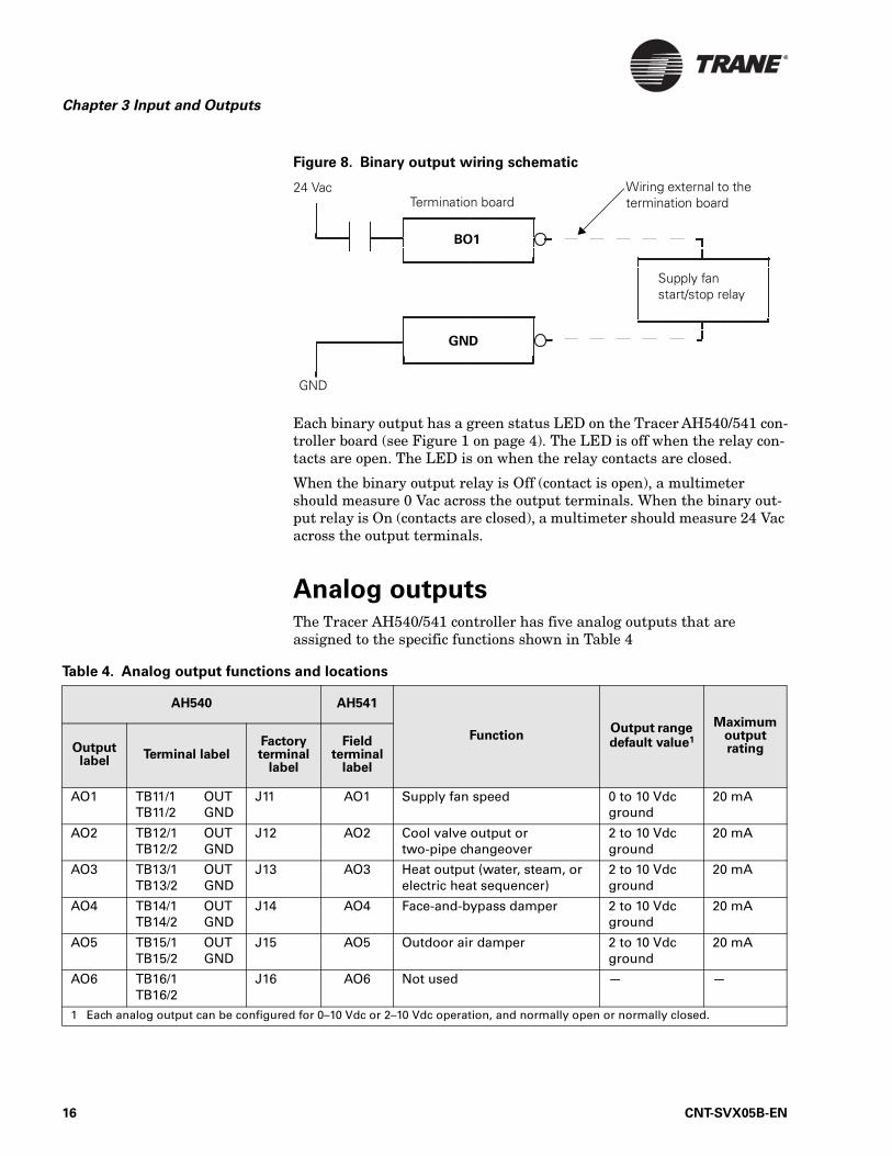
Figure 8. Binary output wiring schematic
Each binary output has a green status LED on the Tracer AH540/541 con-troller board (see Figure 1 on page 4). The LED is off when the relay con-tacts are open. The LED is on when the relay contacts are closed.
When the binary output relay is Off (contact is open), a multimeter should measure 0 Vac across the output terminals. When the binary out-put relay is On (contacts are closed), a multimeter should measure 24 Vac across the output terminals.
Analog outputs The Tracer AH540/541 controller has five analog outputs that are assigned to the specific functions shown in Table 4
Termination board24 Vac
GND
GND
BO1
Supply fan start/stop relay
Wiring external to the termination board
Table 4. Analog output functions and locations
AH540 AH541
FunctionOutput range default value1
Maximum output ratingOutput
labelTerminal label
Factoryterminal
label
Field terminal
label
AO1 TB11/1 OUTTB11/2 GND
J11 AO1 Supply fan speed 0 to 10 Vdcground
20 mA
AO2 TB12/1 OUTTB12/2 GND
J12 AO2 Cool valve output or two-pipe changeover
2 to 10 Vdcground
20 mA
AO3 TB13/1 OUTTB13/2 GND
J13 AO3 Heat output (water, steam, or electric heat sequencer)
2 to 10 Vdcground
20 mA
AO4 TB14/1 OUTTB14/2 GND
J14 AO4 Face-and-bypass damper 2 to 10 Vdcground
20 mA
AO5 TB15/1 OUTTB15/2 GND
J15 AO5 Outdoor air damper 2 to 10 Vdcground
20 mA
AO6 TB16/1TB16/2
J16 AO6 Not used — —
1 Each analog output can be configured for 0–10 Vdc or 2–10 Vdc operation, and normally open or normally closed.
16 CNT-SVX05B-EN
Analog inputs
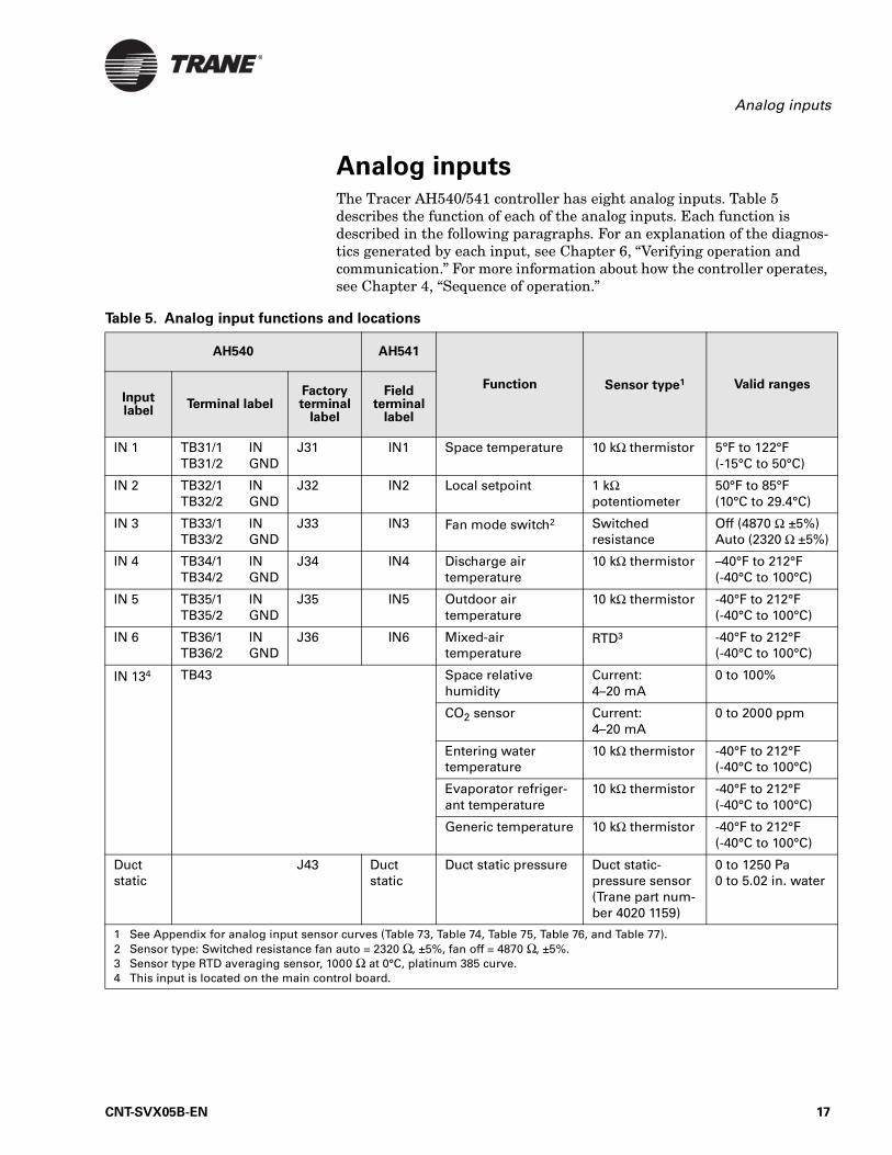
Analog inputsThe Tracer AH540/541 controller has eight analog inputs. Table 5 describes the function of each of the analog inputs. Each function is described in the following paragraphs. For an explanation of the diagnos-tics generated by each input, see Chapter 6, “Verifying operation and communication.” For more information about how the controller operates, see Chapter 4, “Sequence of operation.”
Table 5. Analog input functions and locations
AH540 AH541
Function Sensor type1 Valid rangesInput label
Terminal labelFactoryterminal
label
Field terminal
label
IN 1 TB31/1 INTB31/2 GND
J31 IN1 Space temperature 10 kΩ thermistor 5°F to 122°F(-15°C to 50°C)
IN 2 TB32/1 INTB32/2 GND
J32 IN2 Local setpoint 1 kΩ potentiometer
50°F to 85°F(10°C to 29.4°C)
IN 3 TB33/1 INTB33/2 GND
J33 IN3 Fan mode switch2 Switched resistance
Off (4870 Ω ±5%)Auto (2320 Ω ±5%)
IN 4 TB34/1 INTB34/2 GND
J34 IN4 Discharge air temperature
10 kΩ thermistor –40°F to 212°F(-40°C to 100°C)
IN 5 TB35/1 INTB35/2 GND
J35 IN5 Outdoor air temperature
10 kΩ thermistor -40°F to 212°F(-40°C to 100°C)
IN 6 TB36/1 INTB36/2 GND
J36 IN6 Mixed-air temperature
RTD3 -40°F to 212°F(-40°C to 100°C)
IN 134 TB43 Space relative humidity
Current: 4–20 mA
0 to 100%
CO2 sensor Current:4–20 mA
0 to 2000 ppm
Entering water temperature
10 kΩ thermistor -40°F to 212°F(-40°C to 100°C)
Evaporator refriger-ant temperature
10 kΩ thermistor -40°F to 212°F(-40°C to 100°C)
Generic temperature 10 kΩ thermistor -40°F to 212°F(-40°C to 100°C)
Duct static
J43 Duct static
Duct static pressure Duct static-pressure sensor (Trane part num-ber 4020 1159)
0 to 1250 Pa0 to 5.02 in. water
1 See Appendix for analog input sensor curves (Table 73, Table 74, Table 75, Table 76, and Table 77). 2 Sensor type: Switched resistance fan auto = 2320 Ω, ±5%, fan off = 4870 Ω, ±5%.3 Sensor type RTD averaging sensor, 1000 Ω at 0°C, platinum 385 curve.4 This input is located on the main control board.
CNT-SVX05B-EN 17
Chapter 3 Input and Outputs
IN1: Space temperature
Analog input IN1 measures space temperature only. The space tempera-ture is measured with a 10 kΩ thermistor that is included with Trane zone sensors. The Tracer AH540/541 receives the space temperature from either a wired zone sensor or as a communicated value. A communicated value has precedence over a locally wired sensor input. Therefore, the communicated value, when present, is automatically used by the control-ler.
If a Tracer AH540/541 is operating in constant-volume space temperature control mode and the space temperature fails or does not receive a com-municated value, the controller generates a Space Temperature Failure diagnostic.
The space temperature input may also be used to generate timed override On/Cancel requests to the controller. If a momentary short in the space temperature signal occurs, the Tracer AH540/541 interprets the signal as a timed override On request.
The Tracer AH540/541 uses the timed override On request (while the zone is in unoccupied mode) as a request to go to the occupied bypass mode (occupied bypass). The occupied bypass mode lasts for the duration of the occupied bypass time, typically 120 minutes. The occupied bypass time can be changed using the Rover service tool.
Press the Cancel button on the zone sensor to cancel the override request and return the controller to unoccupied mode. This creates a momentary fixed resistance (1.5 kΩ), which sends a Cancel request to the space tem-perature input.
Calibrating IN1
IN1 can be calibrated with the Rover service tool. Add the calibration value to the measured value to determine the effective value. For more information about calibrating this input, see Table 36 on page 76.
IN2: Local setpoint
Analog input IN2 functions as the local (hard-wired) temperature set-point for applications using a Trane zone sensor with a temperature set-point thumbwheel (see “Zone sensors” on page 28). The local setpoint input is configurable (as enabled or disabled) using the Rover service tool. A setpoint value communicated by means of a Comm5 link can also be used for controllers operating on a building automation system. If both hard-wired and communicated setpoint values are present, the controller uses the communicated value. If neither a hard-wired nor a communi-cated setpoint value is present, the controller uses the stored default set-points (configurable using the Rover service tool). If a valid hard-wired or communicated setpoint value is established and then is no longer present, the controller generates a Setpoint Failure diagnostic.
18 CNT-SVX05B-EN
Analog inputs
Calibrating IN2
IN2 can be calibrated with the Rover service tool. Add the calibration value to the measured value to determine the effective value. For more information about calibrating this input, see Table 36 on page 76.
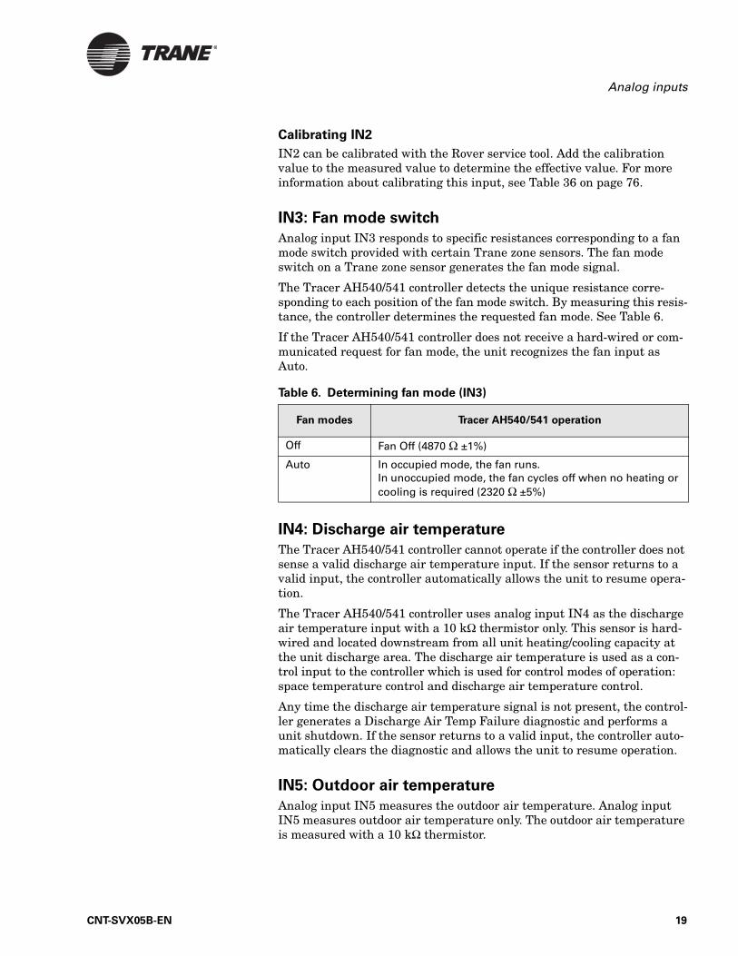
IN3: Fan mode switch
Analog input IN3 responds to specific resistances corresponding to a fan mode switch provided with certain Trane zone sensors. The fan mode switch on a Trane zone sensor generates the fan mode signal.
The Tracer AH540/541 controller detects the unique resistance corre-sponding to each position of the fan mode switch. By measuring this resis-tance, the controller determines the requested fan mode. See Table 6.
If the Tracer AH540/541 controller does not receive a hard-wired or com-municated request for fan mode, the unit recognizes the fan input as Auto.
IN4: Discharge air temperature
The Tracer AH540/541 controller cannot operate if the controller does not sense a valid discharge air temperature input. If the sensor returns to a valid input, the controller automatically allows the unit to resume opera-tion.
The Tracer AH540/541 controller uses analog input IN4 as the discharge air temperature input with a 10 kΩ thermistor only. This sensor is hard-wired and located downstream from all unit heating/cooling capacity at the unit discharge area. The discharge air temperature is used as a con-trol input to the controller which is used for control modes of operation: space temperature control and discharge air temperature control.
Any time the discharge air temperature signal is not present, the control-ler generates a Discharge Air Temp Failure diagnostic and performs a unit shutdown. If the sensor returns to a valid input, the controller auto-matically clears the diagnostic and allows the unit to resume operation.
IN5: Outdoor air temperature
Analog input IN5 measures the outdoor air temperature. Analog input IN5 measures outdoor air temperature only. The outdoor air temperature is measured with a 10 kΩ thermistor.
Table 6. Determining fan mode (IN3)
Fan modes Tracer AH540/541 operation
Off Fan Off (4870 Ω ±1%)
Auto In occupied mode, the fan runs. In unoccupied mode, the fan cycles off when no heating or cooling is required (2320 Ω ±5%)
CNT-SVX05B-EN 19
Chapter 3 Input and Outputs
The controller uses the IN5 value to determine if economizing (free cool-ing) is feasible. For economizing to be allowed, economizing must be enabled and the outdoor air temperature must be below the economizer enable point (default 60°F, configurable). If the outdoor air temperature is equal to or above the economizer enable point, or if there is no value is present, economizing is not allowed. If both hard-wired and communi-cated outdoor air temperature values are present, then the controller uses the communicated value.
If a valid hard-wired or communicated outdoor air temperature value is established and then is no longer present, the controller generates an Outdoor Air Temp Failure diagnostic and economizing is no longer enabled. If the sensor returns to a valid input, the controller automati-cally clears the diagnostic and allows economizer operation.
IN6: Mixed-air temperature
Analog input IN6 is used for mixed-air temperature, with an averaging 1000 Ω (at 32°F [0°C]) RTD sensor only (see Table 75 on page 107). The input is used for mixed-air tempering and outdoor air economizing opera-tions.
The Tracer AH540/541 controller does not allow economizing if the con-troller does not sense a valid mixed-air temperature input. If the sensor returns to a valid input, the controller automatically checks to see if econ-omizer operation is possible.
If a valid mixed-air temperature signal has been established by the RTD sensor, but then the value is no longer present, the controller generates a Mixed Air Temperature Failure diagnostic and disallows economizer operation. When the sensor returns to a valid input, the controller auto-matically clears the diagnostic and checks to see if economizer operation is possible.
IN13: Universal analog input
The universal analog input IN13 (TB43) can be configured for a variety of sensors using the Rover service tool (see “Configuration” on page 73). The input must be configured properly for the sensor wired to the input. The input can be used for only one sensor at a time. The following sensors are supported:
• Space relative humidity (4–20 mA)• CO2 sensor (4–20 mA)• Entering water temperature (10 kΩ thermistor)• Evaporator refrigerant temperature (10 kΩ thermistor)• Generic temperature (10 kΩ thermistor)
Relative humidity
When using the universal analog input with a relative humidity sensor first configure the controller input using the Rover service tool, and then make the wiring connections. The sensor must provide a 4–20 mA signal
20 CNT-SVX05B-EN
Analog inputs
where 20 mA is equal to 100% relative humidity (see Table 76 on page 107).
A space relative humidity input is required for space dehumidification control. If valid space relative humidity input does not exist, space dehu-midification control will be disabled. The controller will accept a valid hard-wired sensor input or a communicated value for space relative humidity. If both a hard-wired and a communicated value exist, the con-troller will use the communicated value for control. The communicated value has priority over the hard-wired input.
When a space relative humidity input is established (either hard-wired or communicated), the controller generates a Humidity Input Failure diag-nostic if the signal is no longer valid, and disables space dehumidifica-tion. If the sensor or communicated value returns to a valid input, the controller automatically clears the diagnostic and allows space dehumidi-fication operation.
CO2 sensor
When using the universal analog input with a CO2 sensor first configure the controller input using the Rover service tool for CO2 and then make the wiring connections. The sensor must provide a 4–20 mA signal, where 20 mA is equal to 2000 ppm (see Table 77 on page 108).
The CO2 input, reported in parts per million, is not used for any AH540/541 control purposes. Instead the input is reported to the building auto-mation system using Comm5 or other devices as a data point. When a CO2 sensor input is established, the controller generates a CO2 Sensor Failure diagnostic if the signal is no longer valid, but the diagnostic has no effect on controller operation. If the sensor returns to a valid input, the controller automatically clears the diagnostic.
Entering water temperature
The universal analog input configured as entering water temperature accepts a 10 kΩ thermistor input (Table 74 on page 106). A valid entering water temperature value (hard-wired or communicated) is required for two-pipe changeover operation for space temperature control air-handling units with one hydronic coil. If both a hard-wired and a communicated value exist, the controller will use the communicated value for two-pipe changeover operation. The communicated value has priority over the hard-wired input.
When valid entering water temperature input is available to the control-ler it is used to determine if hot or cold water capacity is available for space heating and cooling operation. If the entering water temperature input is not valid, the controller assumes hot water exists and disables hydronic cooling operation.
When an entering water temperature input is established (either hard-wired or communicated), the controller generates an Entering Water Temp Failure diagnostic, if the signal is no longer valid, and assumes a cold entering water temperature. If the sensor or communicated value
CNT-SVX05B-EN 21
Chapter 3 Input and Outputs
returns to a valid input, the controller automatically clears the diagnostic and allows two-pipe changeover operation.
Evaporator refrigerant temperature
The universal analog input configured as evaporator refrigerant tempera-ture accepts a 10 kΩ thermistor input (see Table 74 on page 106). A valid evaporator refrigerant temperature is not required for DX cooling opera-tion but does aid in protecting condensing unit compressors.
When a valid evaporator refrigerant temperature input is available to the controller, it is used to determine if the DX cooling capacity should be decreased to prevent low refrigerant temperatures. This function is referred to as defrost operation (see “Defrost operation” on page 65). Low refrigerant temperatures indicate frost conditions on the evaporator and therefore cooling capacity must be reduced to defrost the coil.
When the evaporator refrigerant temperature input is established, the controller generates an Evap Refrigerant Temp Failure diagnostic if the signal is no longer valid, but the diagnostic has no affect on controller operation. If the sensor returns to a valid input, the controller automati-cally clears the diagnostic.
Generic temperature input
The universal analog input configured as generic temperature accepts a 10 kΩ thermistor input. The input can be used in a variety of applications using Tracer Summit. This input has no effect on the controller operation but will report a Generic Temperature Failure diagnostic message if the input becomes invalid or out or range. The diagnostic automatically reset when the input is valid or in range.
J43: Duct static pressure
The duct static pressure input (terminal J43) interfaces with a special-ized pressure transducer only. When a valid duct static pressure value (either hard-wired or communicated) exists and a variable-air-volume supply fan is present, the controller uses this value for duct static pres-sure control.
When a duct static pressure is established, the controller generates a Duct Static Press Failure diagnostic if the signal is no longer valid, and shuts down the unit. When the sensor returns to a valid input, the con-troller automatically clears the diagnostic and allows the unit to resume operation.
The Tracer AH540/541 controller, if configured for variable-air-volume control, cannot operate without a valid duct static pressure input. When the sensor returns to a valid input, the controller resumes unit operation. The controller is not required to have a duct static pressure input for con-stant-volume space temperature or constant-volume discharge air tem-perature control.
22 CNT-SVX05B-EN
Binary inputs
ON/CANCEL buttons on the zone sensor
Momentarily pressing the ON button on the zone sensor during unoccu-pied mode places the controller in occupied bypass mode for 120 minutes. You can adjust the number of minutes the Tracer AH540/541 is placed in the occupied bypass mode by using the Rover service tool. The controller remains in occupied bypass mode until the override time expires or until you press the CANCEL button on the zone sensor.
If the building automation system sends an unoccupied mode command to the controller and ON button on the zone sensor is pressed, the controller goes to occupied bypass and communicates back to the building automa-tion system that its effective occupancy mode is occupied bypass.
If the controller is in the unoccupied mode, regardless of the source (the building automation system or a hard-wired occupancy binary input), pressing the ON button causes the controller to go into the occupied bypass mode for the duration of the configured occupied bypass time.
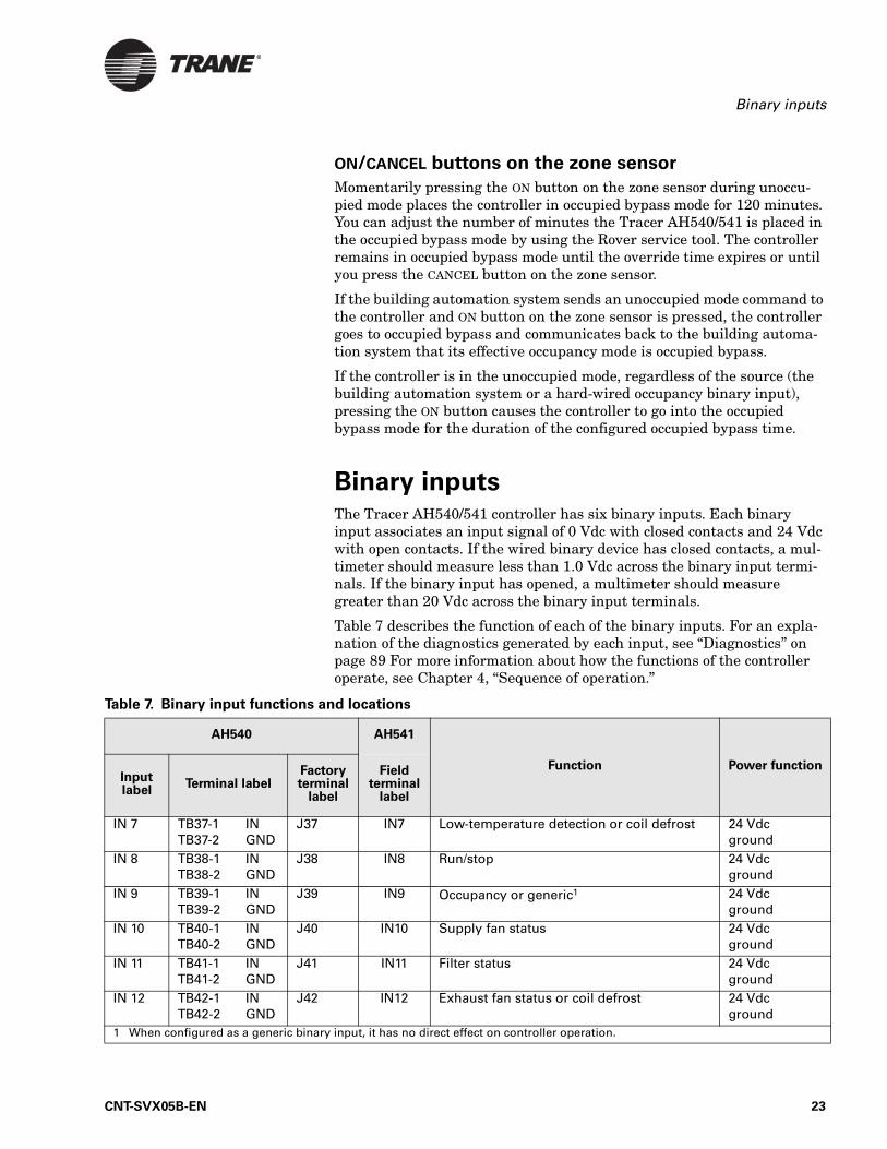
Binary inputsThe Tracer AH540/541 controller has six binary inputs. Each binary input associates an input signal of 0 Vdc with closed contacts and 24 Vdc with open contacts. If the wired binary device has closed contacts, a mul-timeter should measure less than 1.0 Vdc across the binary input termi-nals. If the binary input has opened, a multimeter should measure greater than 20 Vdc across the binary input terminals.
Table 7 describes the function of each of the binary inputs. For an expla-nation of the diagnostics generated by each input, see “Diagnostics” on page 89 For more information about how the functions of the controller operate, see Chapter 4, “Sequence of operation.”
Table 7. Binary input functions and locations
AH540 AH541
Function Power functionInput label
Terminal labelFactoryterminal
label
Field terminal
label
IN 7 TB37-1 INTB37-2 GND
J37 IN7 Low-temperature detection or coil defrost 24 Vdc ground
IN 8 TB38-1 INTB38-2 GND
J38 IN8 Run/stop 24 Vdc ground
IN 9 TB39-1 INTB39-2 GND
J39 IN9 Occupancy or generic1 24 Vdc ground
IN 10 TB40-1 INTB40-2 GND
J40 IN10 Supply fan status 24 Vdc ground
IN 11 TB41-1 INTB41-2 GND
J41 IN11 Filter status 24 Vdc ground
IN 12 TB42-1 INTB42-2 GND
J42 IN12 Exhaust fan status or coil defrost 24 Vdc ground
1 When configured as a generic binary input, it has no direct effect on controller operation.
CNT-SVX05B-EN 23
Chapter 3 Input and Outputs
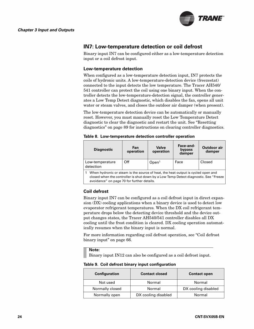
IN7: Low-temperature detection or coil defrost
Binary input IN7 can be configured either as a low-temperature detection input or a coil defrost input.
Low-temperature detection
When configured as a low-temperature detection input, IN7 protects the coils of hydronic units. A low-temperature-detection device (freezestat) connected to the input detects the low temperature. The Tracer AH540/541 controller can protect the coil using one binary input. When the con-troller detects the low-temperature-detection signal, the controller gener-ates a Low Temp Detect diagnostic, which disables the fan, opens all unit water or steam valves, and closes the outdoor air damper (when present).
The low-temperature detection device can be automatically or manually reset. However, you must manually reset the Low Temperature Detect diagnostic to clear the diagnostic and restart the unit. See “Resetting diagnostics” on page 89 for instructions on clearing controller diagnostics.
Coil defrost
Binary input IN7 can be configured as a coil defrost input in direct expan-sion (DX) cooling applications when a binary device is used to detect low evaporator refrigerant temperatures. When the DX coil refrigerant tem-perature drops below the detecting device threshold and the device out-put changes states, the Tracer AH540/541 controller disables all DX cooling until the frost condition is cleared. DX cooling operation automat-ically resumes when the binary input is normal.
For more information regarding coil defrost operation, see “Coil defrost binary input” on page 66.
Table 8. Low-temperature detection controller operation
DiagnosticFan
operationValve
operation
Face-and-bypass damper
Outdoor air damper
Low-temperature detection
Off Open1 Face Closed
1 When hydronic or steam is the source of heat, the heat output is cycled open and closed when the controller is shut down by a Low Temp Detect diagnostic. See “Freeze avoidance” on page 70 for further details.
Note:
Binary input IN12 can also be configured as a coil defrost input.
Table 9. Coil defrost binary input configuration
Configuration Contact closed Contact open
Not used Normal Normal
Normally closed Normal DX cooling disabled
Normally open DX cooling disabled Normal
24 CNT-SVX05B-EN
Binary inputs
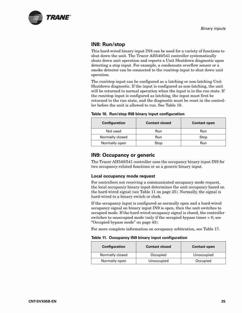
IN8: Run/stop
This hard-wired binary input IN8 can be used for a variety of functions to shut down the unit. The Tracer AH540/541 controller systematically shuts down unit operation and reports a Unit Shutdown diagnostic upon detecting a stop input. For example, a condensate overflow sensor or a smoke detector can be connected to the run/stop input to shut down unit operation.
The run/stop input can be configured as a latching or non-latching Unit Shutdown diagnostic. If the input is configured as non-latching, the unit will be returned to normal operation when the input is in the run state. If the run/stop input is configured as latching, the input must first be returned to the run state, and the diagnostic must be reset in the control-ler before the unit is allowed to run. See Table 10.
IN9: Occupancy or generic
The Tracer AH540/541 controller uses the occupancy binary input IN9 for two occupancy-related functions or as a generic binary input.
Local occupancy mode request
For controllers not receiving a communicated occupancy mode request, the local occupancy binary input determines the unit occupancy based on the hard-wired signal (see Table 11 on page 25). Normally, the signal is hard-wired to a binary switch or clock.
If the occupancy input is configured as normally open and a hard-wired occupancy signal on binary input IN9 is open, then the unit switches to occupied mode. If the hard-wired occupancy signal is closed, the controller switches to unoccupied mode (only if the occupied bypass timer = 0; see “Occupied bypass mode” on page 43).
For more complete information on occupancy arbitration, see Table 17.
Table 10. Run/stop IN8 binary input configuration
Configuration Contact closed Contact open
Not used Run Run
Normally closed Run Stop
Normally open Stop Run
Table 11. Occupancy IN9 binary input configuration
Configuration Contact closed Contact open
Normally closed Occupied Unoccupied
Normally open Unoccupied Occupied
CNT-SVX05B-EN 25
Chapter 3 Input and Outputs
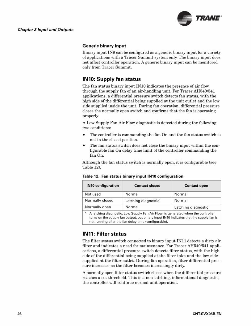
Generic binary input
Binary input IN9 can be configured as a generic binary input for a variety of applications with a Tracer Summit system only. The binary input does not affect controller operation. A generic binary input can be monitored only from Tracer Summit.
IN10: Supply fan status
The fan status binary input IN10 indicates the presence of air flow through the supply fan of an air-handling unit. For Tracer AH540/541 applications, a differential pressure switch detects fan status, with the high side of the differential being supplied at the unit outlet and the low side supplied inside the unit. During fan operation, differential pressure closes the normally open switch and confirms that the fan is operating properly.
A Low Supply Fan Air Flow diagnostic is detected during the following two conditions:
• The controller is commanding the fan On and the fan status switch is not in the closed position.
• The fan status switch does not close the binary input within the con-figurable fan On delay time limit of the controller commanding the fan On.
Although the fan status switch is normally open, it is configurable (see Table 12).
IN11: Filter status
The filter status switch connected to binary input IN11 detects a dirty air filter and indicates a need for maintenance. For Tracer AH540/541 appli-cations, a differential pressure switch detects filter status, with the high side of the differential being supplied at the filter inlet and the low side supplied at the filter outlet. During fan operation, filter differential pres-sure increases as the filter becomes increasingly dirty.
A normally open filter status switch closes when the differential pressure reaches a set threshold. This is a non-latching, informational diagnostic; the controller will continue normal unit operation.
Table 12. Fan status binary input IN10 configuration
IN10 configuration Contact closed Contact open
Not used Normal Normal
Normally closed Latching diagnostic1 Normal
Normally open Normal Latching diagnostic1
1 A latching diagnostic, Low Supply Fan Air Flow, is generated when the controller turns on the supply fan output, but binary input IN10 indicates that the supply fan is not running after the fan delay time (configurable).
26 CNT-SVX05B-EN
Binary inputs
Although the filter status switch is normally open, it is configurable (see Table 13).
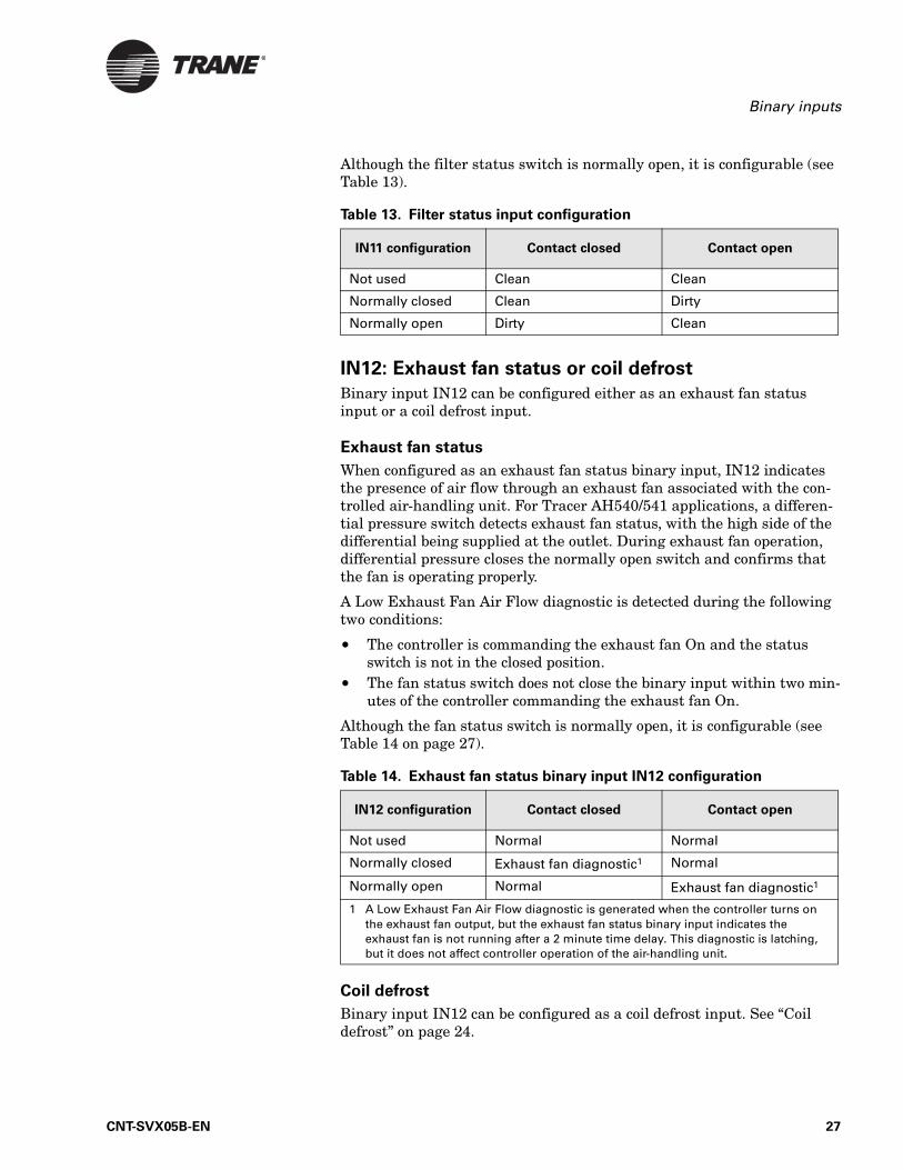
IN12: Exhaust fan status or coil defrost
Binary input IN12 can be configured either as an exhaust fan status input or a coil defrost input.
Exhaust fan status
When configured as an exhaust fan status binary input, IN12 indicates the presence of air flow through an exhaust fan associated with the con-trolled air-handling unit. For Tracer AH540/541 applications, a differen-tial pressure switch detects exhaust fan status, with the high side of the differential being supplied at the outlet. During exhaust fan operation, differential pressure closes the normally open switch and confirms that the fan is operating properly.
A Low Exhaust Fan Air Flow diagnostic is detected during the following two conditions:
• The controller is commanding the exhaust fan On and the status switch is not in the closed position.
• The fan status switch does not close the binary input within two min-utes of the controller commanding the exhaust fan On.
Although the fan status switch is normally open, it is configurable (see Table 14 on page 27).
Coil defrost
Binary input IN12 can be configured as a coil defrost input. See “Coil defrost” on page 24.
Table 13. Filter status input configuration
IN11 configuration Contact closed Contact open
Not used Clean Clean
Normally closed Clean Dirty
Normally open Dirty Clean
Table 14. Exhaust fan status binary input IN12 configuration
IN12 configuration Contact closed Contact open
Not used Normal Normal
Normally closed Exhaust fan diagnostic1 Normal
Normally open Normal Exhaust fan diagnostic1
1 A Low Exhaust Fan Air Flow diagnostic is generated when the controller turns on the exhaust fan output, but the exhaust fan status binary input indicates the exhaust fan is not running after a 2 minute time delay. This diagnostic is latching, but it does not affect controller operation of the air-handling unit.
CNT-SVX05B-EN 27
Chapter 3 Input and Outputs
Zone sensorsThe controller accepts the following zone sensor inputs:
• Space temperature measurement (10 kΩ thermistor)• Zone sensor setpoint thumbwheel (either internal or external on the
zone sensor module) (see Table 73 on page 106)• Fan mode switch• Timed override On request• Timed override Cancel request• Communication jack• Service pin message request
Space temperature measurement
Trane zone sensors use a 10 kΩ thermistor to measure the space temper-ature. Typically, zone sensors are wall-mounted in the room and include a space temperature thermistor. A valid space temperature input is required for the controller to operate in space temperature control.
If both a hard-wired and communicated space temperature value exist, the controller ignores the hard-wired space temperature input and uses the communicated value.
Zone sensor setpoint thumbwheel
Zone sensors with an internal or external setpoint thumbwheel (1 kΩ) provide the Tracer AH540/541 controller with a local setpoint (50ºF to 85ºF [10ºC to 29.4ºC]). An internal setpoint thumbwheel is concealed under the front cover of the zone sensor. To access it, remove the zone sen-sor cover. An external setpoint thumbwheel (when present) is accessible from the front cover of the zone sensor.
See “Zone sensor setpoint thumbwheel” on page 36 for an explanation of how the controller determines the setpoint.
Fan mode switch
The zone sensor fan mode switch provides the controller with a fan request signal (Off, Auto). If the fan control request is communicated to the controller, the controller ignores the hard-wired fan mode switch input and uses the communicated value.
The zone sensor fan mode switch input can be enabled or disabled through configuration using the Rover service tool. If the zone sensor switch is disabled, the controller resorts to the Auto fan mode.
When the fan mode switch is placed in the Off position, the controller does not control any unit capacity. The unit remains powered and all out-puts are driven Closed or Off.
Upon a loss of signal on the fan speed input, the controller reports a diag-nostic and reverts to using the Auto fan mode of operation.
28 CNT-SVX05B-EN
Zone sensors
ON/CANCEL buttons
Some Trane zone sensor modules include timed override ON and CANCEL buttons. Use the timed override ON and CANCEL buttons to place the con-troller in override (occupied bypass mode) and to cancel the override request.
The controller always recognizes the timed override ON button. If some-one presses the zone sensor timed override ON button, the controller ini-tializes the bypass timer to 120 minutes (adjustable).
If the controller is unoccupied when someone presses the ON button for two seconds, the controller immediately changes to occupied bypass mode and remains in the mode until either the timer expires or someone presses the zone sensor’s timed override CANCEL button. If the ON button is pressed during occupied bypass mode before the timer expires, the con-troller re-initializes the bypass timer to 120 minutes.
If the controller is in any mode other than unoccupied when someone presses the ON button, the controller initializes the bypass time to 120 minutes. As time expires, the bypass timer continues to decrement. During this time, if the controller changes from its current mode to unoc-cupied (perhaps due to a change based on the system time-of-day sched-ule), the controller switches to occupied bypass mode for the remainder of the bypass time or until someone presses the zone sensor timed override CANCEL button.
Zone sensor communication jack
Use the RJ-11 communication jack (present on some zone sensor mod-ules) as the connection point from the Rover service tool to the communi-cation link when the communication jack is wired to the communication link at the controller. By accessing the communication jack via Rover, you gain communication access to any controller on the link.
Service Pin message request
Pressing the zone sensor ON button for ten seconds and then releasing it causes the controller to transmit a Service Pin message. The Service Pin message can be useful for installing the controller on a communication network. (See the Rover Operation and Programming guide, EMTX-SVX01E-EN, for more information).
Zone sensor wiring connections
Typical Trane zone sensor wiring connections with a fan mode switch are as follows:
• 1: Space temperature• 2: Common• 3: Setpoint• 4: Fan mode
CNT-SVX05B-EN 29
Chapter 3 Input and Outputs
• 5: Communications• 6: Communications
Typical Trane zone sensor wiring connections without a fan mode switch are as follows:
• 1: Space temperature• 2: Common• 3: Setpoint• 5: Communications• 6: Communications
30 CNT-SVX05B-EN
Chapter 4
Sequence of operation
The Tracer AH540/541 is a configurable controller. All of the controller sequences of operation are predefined with no need for programming the controller. Configurable parameters are provided to allow the user to adjust the controller operation. For example, the minimum occupied out-door air damper position can be changed.
All configuration parameters are set to defaults predetermined through extensive air-handling unit testing in several different operating condi-tions. The factory default settings are also based on the air-handling unit configuration and order information.
Control modesThe Tracer AH540/541 controller is configurable to operate in one of two air-handling temperature control modes:
• Space temperature control• Discharge air temperature control
When the AH540/541 is configured for space temperature control, it con-forms to the LonMark® Space Comfort Controller (SCC) profile. When the AH540/541 is configured for discharge air temperature control, it con-forms to the LonMark® Discharge Air Controller (DAC) profile.
Space temperature control The Tracer AH540/541 controller requires both a space temperature and discharge air temperature sensor to be present for space temperature control operation (also called cascade control). In this control mode, the Tracer AH5405/541 uses the space temperature and the measured dis-charge air temperature to maintain the space temperature at the active space cooling setpoint or the active space heating setpoint. The controller modulates its heating or cooling outputs to control the discharge air tem-perature to the discharge air temperature setpoint. This calculated dis-charge air temperature setpoint is the desired discharge air temperature
Note:
Some sequences in this chapter are specific to the space tem-perature control mode and some are specific to the discharge air temperature control mode. Some sequences are common to both modes, but operate differently. Where mode-dependent differ-ences exist, they are explained in this chapter.
CNT-SVX05B-EN 31
Chapter 4 Sequence of operation
(supply air temperature) that the unit must deliver to maintain space temperature at the space heating or cooling setpoint.
The space temperature can be hard-wired to analog input IN1 on the ter-mination board (10 kΩ thermistor only) or can be communicated to the controller via Comm5. Similarly, a setpoint can be provided with either a hard-wired setpoint thumbwheel to analog input IN2 on the controller, with a communicated value, or by using the stored default setpoints in the controller. The discharge air temperature must be a hard-wired ana-log input IN4 to the termination board (10 kΩ thermistor only).
The controller heat/cool mode is determined by either a communicated request or by the controller itself, when the heat/cool mode is Auto. When the heat/cool mode is Auto, the controller compares the active space set-point and the active space temperature and decides if the space needs heating or cooling.
The Tracer AH540/541 controller must have a valid space temperature and discharge air temperature input to operate space temperature con-trol.
When the controller is configured for a supply fan and space temperature control, the controller will not operate the unit if the space temperature or discharge air temperature sensors are missing or have failed.
The space temperature control algorithm uses two control loops: a space temperature loop and a discharge air temperature loop. The space tem-perature control loop compares the active heat/cool space setpoint and the space temperature and calculates a discharge air temperature setpoint. The calculated discharge air temperature setpoint range is bound by con-figurable heating (maximum) and cooling (minimum) limits.
The discharge air temperature loop compares the discharge air tempera-ture to the calculated discharge air temperature setpoint (calculated by the space temperature loop), and calculates a heat or cool capacity to respond to the discharge air temperature setpoint.
The capacity calculation, as a result of the discharge air temperature con-trol loop, is used to drive the air-handling unit actuators to maintain space temperature at the space temperature setpoint.
Control gains
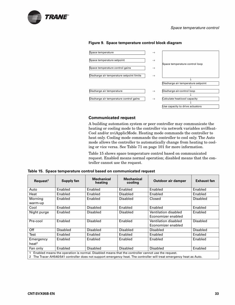
Figure 9 on page 33 illustrates the separate control for the space-temper-ature control loop and discharge air temperature control loop. The gain parameter values that control the different loops have been determined through extensive testing of different types of heating or cooling capaci-ties and at operating conditions of the air-handling unit.
Heating/cooling mode control
The heating or cooling mode of the controller can be determined two ways:
• Communicated request• Automatically by the controller
32 CNT-SVX05B-EN
Space temperature control
Figure 9. Space temperature control block diagram
Communicated request
A building automation system or peer controller may communicate the heating or cooling mode to the controller via network variables nviHeat-Cool and/or nviApplicMode. Heating mode commands the controller to heat only. Cooling mode commands the controller to cool only. The Auto mode allows the controller to automatically change from heating to cool-ing or vice versa. See Table 71 on page 101 for more information.
Table 15 shows space temperature control based on communicated request. Enabled means normal operation; disabled means that the con-troller cannot use the request.
Space temperature →
Space temperature setpoint →Space temperature control loop
Space temperature control gains →
Discharge air temperature setpoint limits →↓
Discharge air temperature setpoint↓
Discharge air temperature → Discharge-air-control loop↓
Discharge air temperature control gains → Calculate heat/cool capacity↓
Use capacity to drive actuators
Table 15. Space temperature control based on communicated request
Request1 Supply fanMechanical
heatingMechanical
coolingOutdoor air damper Exhaust fan
Auto Enabled Enabled Enabled Enabled EnabledHeat Enabled Enabled Disabled Enabled EnabledMorning warm-up
Enabled Enabled Disabled Closed Disabled
Cool Enabled Disabled Enabled Enabled EnabledNight purge Enabled Disabled Disabled Ventilation disabled
Economizer enabledEnabled
Pre-cool Enabled Disabled Enabled Ventilation disabled Economizer enabled
Disabled
Off Disabled Disabled Disabled Disabled DisabledTest Enabled Enabled Enabled Enabled EnabledEmergency heat2
Enabled Enabled Enabled Enabled Enabled
Fan only Enabled Disabled Disabled Disabled Enabled1 Enabled means the operation is normal. Disabled means that the controller cannot use the request.2 The Tracer AH540/541 controller does not support emergency heat. The controller will treat emergency heat as Auto.
CNT-SVX05B-EN 33
Chapter 4 Sequence of operation
Auto mode
A communicated request of Auto or the controller default operation (Auto) can place the unit into heating or cooling mode. When the controller auto-matically determines the heating or cooling mode while in Auto mode, the unit switches to the desired mode based on the control algorithm.
If the Tracer AH540/541 controller is operating space temperature con-trol, it uses the space temperature and space temperature setpoint to automatically determine heat or cool mode of operation. When the con-troller first powers up or after a reset, it makes an initial determination if the heat/cool mode should be heat or cool. If the controller is configured as heating and cooling, the controller determines the appropriate mode.
For example, if the initial space temperature is less than the occupied space heat setpoint then the initial heat/cool mode is heating. The heat/cool mode for a cool-only unit is always cool. The heat/cool mode for a heat-only unit is always heat.
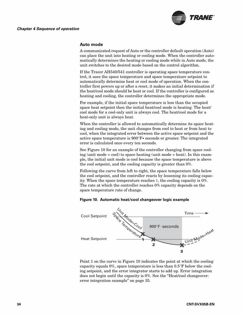
When the controller is allowed to automatically determine its space heat-ing and cooling mode, the unit changes from cool to heat or from heat to cool, when the integrated error between the active space setpoint and the active space temperature is 900°F• seconds or greater. The integrated error is calculated once every ten seconds.
See Figure 10 for an example of the controller changing from space cool-ing (unit mode = cool) to space heating (unit mode = heat). In this exam-ple, the initial unit mode is cool because the space temperature is above the cool setpoint, and the cooling capacity is greater than 0%.
Following the curve from left to right, the space temperature falls below the cool setpoint, and the controller reacts by lessening its cooling capac-ity. When the space temperature reaches 1, the cooling capacity is 0%. The rate at which the controller reaches 0% capacity depends on the space temperature rate of change.
Figure 10. Automatic heat/cool changeover logic example
Point 1 on the curve in Figure 10 indicates the point at which the cooling capacity equals 0%, space temperature is less than 0.5°F below the cool-ing setpoint, and the error integrator starts to add up. Error integration does not begin until the capacity is 0%. See the “Heat/cool changeover: error integration example” on page 35.
34 CNT-SVX05B-EN
Space temperature control
Point 2 on the curve indicates the active heat setpoint. The space temper-ature must fall below the active heat setpoint before the controller can change to heating. Conversely, the space temperature must rise above the active cooling setpoint before the controller can change to cooling.
Point 3 on the curve indicates the point at which the controller switches to heat (from cool) after the error integrator exceeds 900°F • seconds.
The controller must be able to heat before it will switch to heat. A unit that cannot heat will not switch to heat. A unit that cannot cool will not switch to cool.
Heat/cool changeover: error integration example
If the active space temperature is 66.5°F, the current mode is cooling, the cooling capacity is 0°F, and the space cooling setpoint is 70°F. The error calculation is 70 – 0.5 – 66.5 = 3°F. If the same error exists for 60 seconds, the error integration term is (3°F • 60 seconds = 180°F seconds). There-fore, after five minutes (3°F • 300 seconds = 900°F seconds), the controller will switch from cooling to heating mode if the space temperature is below the occupied heating setpoint.
Cooling operation
The heating and cooling space setpoint high and low limits are always applied to the occupied and occupied standby setpoints. During the cool-ing mode, the Tracer AH540/541 controller attempts to maintain the active space temperature at the active space cooling setpoint. Based on the controller occupancy mode, the active space cooling setpoint is one of the following:
• Occupied cooling setpoint• Occupied standby cooling setpoint• Unoccupied cooling setpoint
The cooling outputs are controlled based on the unit configuration and the required machine cooling capacity. At 0% machine cooling capacity, the cooling valve is closed and the outdoor air damper is at its minimum position. As the required machine cooling capacity increases, the cooling valve and/or the outdoor air damper opens above their minimum posi-tions.
The discharge air temperature control algorithm calculates a desired dis-charge air temperature to maintain the space cooling setpoint. Cool capacity is controlled to achieve the desired discharge air setpoint. Heat capacity can also be used to temper cold outdoor air conditions to main-tain ventilation and the discharge air setpoint.
The outdoor air damper is used for cooling whenever economizing is pos-sible and there is a need for cooling. If economizing is not possible, it will not be used in cooling. If economizing is possible, it is always the first stage of cooling. See “Outdoor air damper operation” on page 56 for more information.
CNT-SVX05B-EN 35
Chapter 4 Sequence of operation
Heating operation
In the heating mode, the Tracer AH540/541 controller attempts to main-tain the space temperature at the active heating setpoint. Based on the controller occupancy mode, the active space heating setpoint is one of the following:
• Occupied heating setpoint• Occupied standby heating setpoint• Unoccupied heating setpoint
The outputs are controlled based on the unit configuration and the required machine heating capacity. At 0% machine heating capacity, the heating capacity is at its minimum position. As the required machine heating capacity increases, the heating capacity is opened above its mini-mum position. At 100% machine heating capacity, the heating capacity is open to its maximum position.
The economizer outdoor air damper is never used as a source of heating. The economizer damper is used only for ventilation when the unit is heat-ing. For more information, see “Outdoor air damper operation” on page 56.
Space temperature setpoint arbitration
The space temperature setpoint can be communicated either by a build-ing automation system or peer-to-peer using a binding (see “Communica-tion with other controllers” on page 3). When the Tracer AH540/541 is in occupied mode, occupied standby mode, or occupied bypass mode, a com-municated setpoint takes precedence over a local (hard-wired) setpoint. When neither a communicated nor a local (hard-wired) setpoint is present, the controller uses the locally stored default heating and cooling setpoints.
The exception is when the controller is in unoccupied mode. Then the con-troller always uses locally stored default unoccupied setpoints. These set-points are configured at the factory prior to shipment. Use the Rover service tool to modify these default unoccupied setpoints.
Zone sensor setpoint thumbwheel
Zone sensors with an internal or external setpoint thumbwheel (1 kΩ) provide the Tracer AH540/541 controller with a local setpoint (50ºF to 85ºF [10ºC to 29.4ºC]). An internal setpoint thumbwheel is concealed under the front cover of the zone sensor. To access it, remove the zone sen-sor cover. An external setpoint thumbwheel (when present) is accessible from the front cover of the zone sensor.
When the local (hard-wired) setpoint thumbwheel is used to determine the setpoints, all unit setpoints are calculated based on the local setpoint value, the configured setpoints, and the active mode of the controller.
36 CNT-SVX05B-EN
Space temperature control
For example, assume the controller is configured with the following default setpoints:
• Unoccupied cooling setpoint 85°F (29.4ºC)• Occupied standby cooling setpoint 76°F (24.4ºC)• Occupied cooling setpoint 74°F (23.3ºC)• Occupied heating setpoint 70°F (21.1ºC)• Occupied standby heating setpoint 66°F (18.9ºC)• Unoccupied heating setpoint 60°F (15.6ºC)
Absolute Setpoint Offset = Setpoint Input – Mean Setpoint
From the default setpoints in this example, the mean setpoint is the mean of the occupied cooling and heating setpoints, which is 72°F [(74+70) / 2]. The absolute setpoint offset is the difference between the setpoint input and the mean setpoint.
Assume a thumbwheel setpoint input of 73°F, resulting in an absolute setpoint offset of 1°F (73–72=1). The controller adds the absolute setpoint offset (1°F) to occupied and occupied standby default setpoints to derive the effective setpoints, as follows.
• Unoccupied cooling setpoint 85°F (same as default)• Occupied standby cooling setpoint 77°F (default+1=77)• Occupied cooling setpoint 75°F (default+1=75)• Occupied heating setpoint 71°F (default+1=71)• Occupied standby heating setpoint 67°F (default+1=67)• Unoccupied heating setpoint 60°F (same as default)
When a building automation system or other controller communicates a setpoint to the controller, the controller ignores the hard-wired setpoint input and uses the communicated value. The exception is the unoccupied mode, when the controller always uses the stored default unoccupied set-points.
After the controller completes all setpoint calculations based on the requested setpoint, the occupancy mode, the heating and cooling mode, and other factors, the calculated setpoint is validated against the follow-ing setpoint limits:
• Heating setpoint high limit• Heating setpoint low limit• Cooling setpoint high limit• Cooling setpoint low limit
These setpoint limits only apply to the occupied and occupied standby heating and cooling setpoints. These setpoint limits do not apply to the unoccupied heating and cooling setpoints stored in the controller configu-ration.
Unit configuration also exists to enable or disable the local (hard-wired) setpoint at the zone sensor module. This parameter provides additional flexibility to allow you to apply communicated, hard-wired, or default set-points without having to make physical wiring changes to the controller.
CNT-SVX05B-EN 37

Chapter 4 Sequence of operation
Discharge air temperature control The controller requires a discharge air temperature sensor (10 kΩ ther-mistor only) to operate in the discharge air temperature control mode. Discharge air temperature control modulates the heating or cooling out-puts to maintain discharge air temperature at the discharge air tempera-ture setpoint regardless of the entering air conditions of the air-handling unit.
Figure 11 shows the steps the Tracer AH540/541 controller takes to con-trol discharge air. First the controller determines if a communicated dis-charge-air heating setpoint and discharge-air cooling setpoint are present. The communicated setpoint has precedence over the configured (default) setpoint. If no communicated value is present, the controller uses the configured discharge air temperature setpoint.
Figure 11. Discharge air temperature control flow diagram
Discharge air temperature setpoint minimum and maximum limits are placed on the discharge air setpoint depending on the effective heat or cool mode. If the effective heat/cool mode is cool, the maximum discharge-air cooling setpoint limit and minimum discharge-air cooling setpoint limit the discharge-air cooling setpoint. See Chapter 5, “Configuration” for more information about discharge-air heating and cooling setpoint limits.
The effective discharge air temperature setpoint is determined from:
• Communicated or configured discharge air temperature setpoint value
• Minimum and maximum heat/cool setpoint limits• Effective heat/cool mode
Configured value: discharge-air heating setpointdischarge-air cooling setpoint
→ The communicated heat/cool setpoint value has precedence over the configured discharge air tempera-ture heat/cool setpoint
↓ ↓ ↓
Communicated value:discharge-air heating setpointdischarge-air cooling setpoint
→ Discharge-air heating setpoint
Discharge-air cooling setpoint
↓ ↓Discharge-air heating setpoint limits
Discharge-air cooling setpoint limits
↓ ↓Effective heat/cool mode → Effective discharge air temperature setpoint
↓Discharge air temperature (wired sensor)
→ Discharge air temperature control loop
↓Discharge air temperature control
gains→ Calculate heat/cool capacity
↓Use capacity to drive actuators
38 CNT-SVX05B-EN
Discharge air temperature control
See Table 16 and Table 17 for an example of how the controller deter-mines the effective discharge air temperature setpoint.
Since the effective heat cool mode is cool and the communicated value has precedence over the local configuration value, the discharge-air cooling setpoint is 50°F. The maximum and minimum discharge-air cooling set-point limits are then applied to determine an effective discharge-air tem-perature setpoint of 53 °F, from Table 16.
In this example, if the effective heat cool mode is Heat, the effective dis-charge air temperature setpoint would be 100°F.
The discharge air temperature control loop uses the effective discharge air temperature setpoint, discharge air temperature (from the wired sen-sor), and the configured control gains to calculate an output capacity for the end devices.
Heating/cooling mode control
The heating or cooling control mode of the controller can be determined in two ways:
• Communicated request• Automatically by the controller
Communicated request
A building automation system or peer controller may communicate the heating or cooling mode to the controller using network variable nviAp-plicMode. Heating mode commands the controller to heat only. Cooling mode commands the controller to cool only. The Auto mode allows the con-troller to automatically change from heating to cooling or cooling to heat-ing. See Table 72 on page 103.
Table 16. Example of configuration parameters
Discharge-air cooling setpoint 55ºF (18.2ºC)
Maximum discharge-air cooling setpoint 68ºF (20.0ºC)
Minimum discharge-air cooling setpoint 50ºF (10.0ºC)
Discharge-air heating setpoint 100ºF (37.8ºC)
Maximum discharge-air heating setpoint1 104ºF (40.0ºC)
Minimum discharge-air heating setpoint 86ºF (30.0ºC)
1 When the controller is applied to an air-handling unit with a draw-through supply fan, the maximum discharge-air heating setpoint should be set to 104ºF (default set-point). This prevents the discharge air temperature from exceeding the high temper-ature limit of the supply fan motor. Exceeding the motor temperature limit can cause premature failures.
Table 17. Example of communicated values
Discharge-air cooling setpoint input 50°F (10.0ºC)
Discharge-air heating setpoint input None
Effective heat cool mode Cool
CNT-SVX05B-EN 39
Chapter 4 Sequence of operation
Auto mode
A communicated request of Auto or the controller default operation (Auto) can place the unit into cooling mode. A zone temperature input is required for discharge air temperature control when auto heat/cool changeover is desired. When the controller automatically determines the heating or cooling mode using auto mode, the unit switches to the desired mode based on the control algorithm and the relationship between zone temperature to the configured daytime warm up start and stop setpoints. See daytime warm up in configuration section of this manual.
When the controller first powers up or after a reset, it makes an initial determination if the discharge air temperature control mode should be heating or cooling. The discharge demand for a cooling-only unit is always cooling. The discharge demand for a heating only unit is always heating. A unit that can heat or cool initially starts in cooling mode.
Power-up sequenceThis sequence applies to both space temperature control and discharge air temperature control.
When 24 Vac power is initially applied to the AH540/541 controller, the following sequence occurs:
1. Green Status LED turns On.
2. All binary outputs are controlled to their de-energized state, and ana-log outputs are set to the normally closed output voltage.
3. The controller reads the inputs to determine initial values.
4. Power-up control wait feature is applied. The controller waits 300 seconds to allow ample time for the communicated control data to arrive. If after 300 seconds, the controller has not received any com-municated control data, the unit assumes stand-alone operation.
5. Normal operation begins assuming no diagnostics have been generated.
Manual output test can be initiated at any time in the power-up sequence or during normal operation. Refer to the “Performing a manual output test” on page 84.
40 CNT-SVX05B-EN
Occupancy modes
Occupancy modes The occupancy mode can be either communicated to the controller or hard-wired using the occupancy binary input IN9.
The valid occupancy modes for space temperature control are:
• Occupied• Unoccupied• Occupied standby• Occupied bypass
The valid occupancy modes for discharge air temperature control are:
• Occupied• Unoccupied• Occupied bypass
Occupied mode
The occupied mode is the normal operating mode for occupied spaces or daytime operation. The Tracer AH540/541 controller operates this sequence according to the configured control mode.
Space temperature control: Occupied mode
If configured for space temperature control, the controller attempts to maintain the space temperature at the active occupied heating or cooling space setpoint, based on the measured space temperature, the discharge air temperature, the active setpoint, and the proportional/integral control algorithm. Additional information related to controller setpoints can be found in “Space temperature setpoint arbitration” on page 36.
Discharge air temperature control: Occupied mode
If configured for discharge air temperature control, the controller main-tains the discharge air temperature at the configured discharge air heat-ing or cooling setpoint. The default occupied mode of the controller is cooling. In the occupied mode, the controller communicated application mode input (nviApplicMode) and heat/cool mode input (nviHeatCool) determine the controller heating and cooling setpoint. See Table 72 on page 103 for heating and cooling control modes of operation.
Unoccupied mode
The unoccupied mode is the normal operating mode for unoccupied spaces or nighttime operation. When the controller is in the unoccupied mode, the controller attempts to maintain the space temperature between the configured unoccupied heating and cooling setpoints, based on the mea-sured space temperature. The Tracer AH540/541 controller operates according to the configured control mode.
CNT-SVX05B-EN 41
Chapter 4 Sequence of operation
Space temperature control: Unoccupied mode
In unoccupied mode, if configured for space temperature control, the sup-ply fan is Off whenever the space temperature is between the unoccupied heating and cooling setpoints. If the space temperature rises above the unoccupied cooling setpoint the Tracer AH540/541 turns On the supply fan and provides cooling at the unoccupied cooling setpoint.
If the space temperature drops below the unoccupied heating setpoint the controller turns On the supply fan and provides heating at the unoccu-pied heating setpoint. See Table 43 on page 78.
Discharge air temperature control: Unoccupied mode
In unoccupied mode, if configured for discharge air temperature control, the controller must have either a hard-wired or communicated space tem-perature input from the Tracer Summit building automation system.
In unoccupied mode, the supply fan is Off whenever the space tempera-ture is between the unoccupied heating and cooling setpoints. If the space temperature rises above the unoccupied cooling setpoint the Tracer AH540/541 turns On the supply fan and provides cooling at the discharge air cooling setpoint.
If the space temperature drops below the unoccupied heating setpoint the controller turns On the supply fan and provides heating at the discharge air heating setpoint. See Table 44 on page 79.
Note that primary heating or cooling capacity is defined by unit type and whether heating or cooling is enabled or disabled. For example, if the economizer is enabled and possible, it will be the primary cooling capac-ity. If hydronic heating is possible, it will be the primary heating capacity.
Occupied standby mode
If configured for space temperature control, the controller uses the occu-pied standby mode to reduce heating and cooling demands during occu-pied hours when a space is vacant or unoccupied. For example, the controller may use occupied standby mode for a classroom while the stu-dents are out of the room.In the occupied standby mode, the controller uses the occupied standby cooling and heating setpoints. Because the occupied standby setpoints typically cover a wider range than the occu-pied setpoints, the Tracer AH540/541 controller reduces the demand for heating and cooling the space. Also, the outdoor air economizer damper uses the economizer standby minimum position to reduce the heating and cooling demands.
Occupied standby is a mode in which the controller has received an occu-pied request from Tracer Summit, but has also received a local unoccu-pied binary input IN9 signal. For example, an unoccupied conference room (as sensed by a local occupancy sensor) in an occupied building (as commanded by a Tracer Summit system) is in occupied standby mode. When the conference room becomes occupied with people, the local occu-pancy sensor changes the controller mode to occupied.
42 CNT-SVX05B-EN
Occupancy modes
The controller can be placed into the occupied standby mode when a com-municated occupancy request is combined with the local (hard-wired) occupancy binary input signal. When the communicated occupancy request is unoccupied, the occupancy binary input (if present) does not affect the controller occupancy. When the communicated occupancy request is occupied, the controller uses the local occupancy binary input to switch between the occupied and occupied standby modes.
During occupied standby mode, the controller economizer damper posi-tion goes to the economizer standby minimum position. The economizer standby minimum position can be changed using the Rover service tool.
When no occupancy request is communicated, the occupancy binary input switches the controller operating mode between occupied and unoccupied. When no communicated occupancy request exists, the unit cannot switch to occupied standby mode.
Occupied bypass mode
If configured for either space temperature control or discharge air tem-perature control, the controller uses occupied bypass mode for timed over-ride conditions. For example, if the controller is in unoccupied mode and someone presses the ON button on the zone sensor, the controller is placed in occupied bypass mode for 120 minutes (adjustable) or until someone presses the CANCEL button on the zone sensor. The controller can be placed in occupied bypass mode by either communicating an occupancy request of Bypass to the controller or by using the timed override ON but-ton on the Trane zone sensor.
When the controller is in unoccupied mode, you can press the ON button on the zone sensor to place the controller into occupied bypass mode for the duration of the bypass time (typically 120 minutes).
If the controller is in the occupied standby mode, you can press the ON button on the zone sensor to place the controller into occupied bypass mode for the duration of the configured bypass time. Typically, the con-troller is in occupied standby mode rather than occupied mode because of the local binary occupancy input.
Sources of occupancy mode control
There are four ways to control the occupancy mode (see Table 16 on page 39):
• Communicated request (usually provided by the building automation system or peer device)
• Pressing the zone sensor timed override ON button (or CANCEL button)• Occupancy binary input (see “Occupancy binary input” for more infor-
mation)• Default operation of the controller (occupied mode)
A communicated request from a building automation system or another peer controller can change the controller occupancy. However, if commu-nication is lost, the controller reverts to the default operating mode (occu-
CNT-SVX05B-EN 43
Chapter 4 Sequence of operation
pied) after 15 minutes (configurable, specified by the “receive heartbeat time”), if no local hard-wired occupancy signal exists.
Occupancy binary input
The Tracer AH540/541 controller uses the occupancy binary input IN9 for two occupancy-related functions. For controllers not receiving a communi-cated occupancy request, the occupancy binary input determines the occupancy of the unit based on the hard-wired signal. Normally, the sig-nal is hard-wired to a binary switch or time clock.
When a hard-wired occupancy signal is open, the unit switches to occu-pied mode (if the occupancy input is configured as normally open). When a hard-wired occupancy signal is closed, the controller switches to unoccu-pied mode.
For controllers that receive a communicated occupancy request from a building automation system, the hard-wired occupancy binary input is used with a communicated occupancy request to place the controller in either occupied mode or occupied standby mode.
In occupied mode, the controller operates according to the occupied set-points. In occupied standby mode, the unit controller operates according to the occupied standby setpoints. When the controller receives a commu-nicated unoccupied request, the controller operates according to the unoc-cupied setpoints regardless of the hard-wired occupancy input state.
If neither the hard-wired binary input nor a communicated request is used to select the occupancy mode, the controller defaults to occupied mode because the occupancy binary input (if present) typically is config-ured as normally open and no occupancy device is connected.
Determining the occupancy mode
The occupancy of the controller is determined by evaluating the combina-tion of three potential communicating inputs, as well as the hard-wired occupancy input and the occupied bypass timer (see Table 16 on page 39). Three different communicating inputs affect controller occupancy mode:
• Occupancy—manual command• Occupancy—schedule• Occupancy—sensor
These inputs provide maximum flexibility, but the number of inputs you decide to use varies with the application and the features available in your building automation system.
Occupancy—manual command
Some communicating devices may request occupancy based on the infor-mation communicated in the network variable (nvoOccManCmd). Trane systems and zone sensors do not communicate this information to the controller, but the Tracer AH540/541 controller accepts this network vari-able as communicated input (nviOccManCmd).
44 CNT-SVX05B-EN
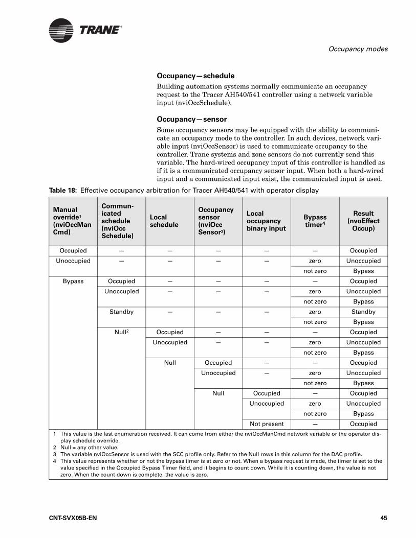
Occupancy modes
Occupancy—schedule
Building automation systems normally communicate an occupancy request to the Tracer AH540/541 controller using a network variable input (nviOccSchedule).
Occupancy—sensor
Some occupancy sensors may be equipped with the ability to communi-cate an occupancy mode to the controller. In such devices, network vari-able input (nviOccSensor) is used to communicate occupancy to the controller. Trane systems and zone sensors do not currently send this variable. The hard-wired occupancy input of this controller is handled as if it is a communicated occupancy sensor input. When both a hard-wired input and a communicated input exist, the communicated input is used.
Table 18: Effective occupancy arbitration for Tracer AH540/541 with operator display
Manual override1 (nviOccManCmd)
Commun-icated schedule (nviOccSchedule)
Local schedule
Occupancy sensor (nviOccSensor3)
Local occupancy binary input
Bypass timer4
Result (nvoEffect
Occup)
Occupied — — — — — Occupied
Unoccupied — — — — zero Unoccupied
not zero Bypass
Bypass Occupied — — — — Occupied
Unoccupied — — — zero Unoccupied
not zero Bypass
Standby — — — zero Standby
not zero Bypass
Null2 Occupied — — — Occupied
Unoccupied — — zero Unoccupied
not zero Bypass
Null Occupied — — Occupied
Unoccupied — zero Unoccupied
not zero Bypass
Null Occupied — Occupied
Unoccupied zero Unoccupied
not zero Bypass
Not present — Occupied
1 This value is the last enumeration received. It can come from either the nviOccManCmd network variable or the operator dis-play schedule override.
2 Null = any other value.3 The variable nviOccSensor is used with the SCC profile only. Refer to the Null rows in this column for the DAC profile.4 This value represents whether or not the bypass timer is at zero or not. When a bypass request is made, the timer is set to the
value specified in the Occupied Bypass Timer field, and it begins to count down. While it is counting down, the value is not zero. When the count down is complete, the value is zero.
CNT-SVX05B-EN 45
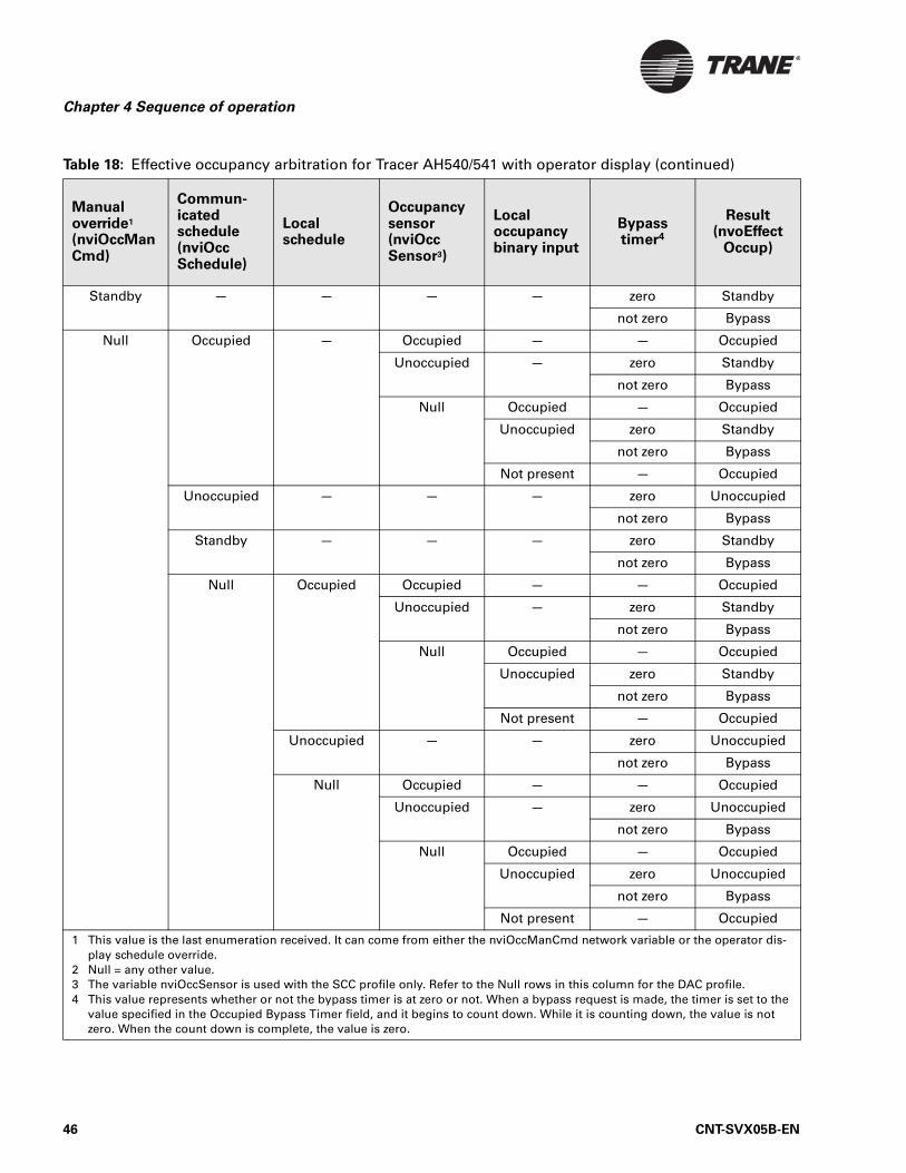
Chapter 4 Sequence of operation
Standby — — — — zero Standby
not zero Bypass
Null Occupied — Occupied — — Occupied
Unoccupied — zero Standby
not zero Bypass
Null Occupied — Occupied
Unoccupied zero Standby
not zero Bypass
Not present — Occupied
Unoccupied — — — zero Unoccupied
not zero Bypass
Standby — — — zero Standby
not zero Bypass
Null Occupied Occupied — — Occupied
Unoccupied — zero Standby
not zero Bypass
Null Occupied — Occupied
Unoccupied zero Standby
not zero Bypass
Not present — Occupied
Unoccupied — — zero Unoccupied
not zero Bypass
Null Occupied — — Occupied
Unoccupied — zero Unoccupied
not zero Bypass
Null Occupied — Occupied
Unoccupied zero Unoccupied
not zero Bypass
Not present — Occupied
Table 18: Effective occupancy arbitration for Tracer AH540/541 with operator display (continued)
Manual override1 (nviOccManCmd)
Commun-icated schedule (nviOccSchedule)
Local schedule
Occupancy sensor (nviOccSensor3)
Local occupancy binary input
Bypass timer4
Result (nvoEffect
Occup)
1 This value is the last enumeration received. It can come from either the nviOccManCmd network variable or the operator dis-play schedule override.
2 Null = any other value.3 The variable nviOccSensor is used with the SCC profile only. Refer to the Null rows in this column for the DAC profile.4 This value represents whether or not the bypass timer is at zero or not. When a bypass request is made, the timer is set to the
value specified in the Occupied Bypass Timer field, and it begins to count down. While it is counting down, the value is not zero. When the count down is complete, the value is zero.
46 CNT-SVX05B-EN
Timed override control
Timed override control This sequence applies to both space temperature control and discharge air temperature control, with differences as noted.
If the zone sensor has a timed override option (ON/CANCEL buttons), push-ing the ON button initiates a timed override request. A timed override request changes the occupancy mode from unoccupied mode to occupied bypass mode. In occupied bypass mode, the controller controls the zone temperature based on the occupied heating or cooling setpoints. The occu-pied bypass time, which resides in the Tracer AH540/541 and defines the duration of the override, is configurable from 0 to 240 minutes. The default value is 120 minutes for space temperature control; the default value is 0 minutes (disabled) for discharge air temperature control. When the occupied bypass time expires, the unit transitions from occupied bypass mode to unoccupied mode. Pushing the CANCEL button cancels the timed override request. A timed override cancel request will end the timed override before the occupied bypass time has expired and will tran-sition the unit from occupied bypass mode to unoccupied mode.
If the controller is in any mode other than unoccupied when the ON but-ton is pressed, the controller still starts the occupied bypass timer with-out changing the mode to occupied bypass. If the controller is placed in unoccupied mode before the occupied bypass timer expires, the controller will be placed in occupied bypass mode and remain in that mode until either the CANCEL button is pressed on the Trane zone sensor or the occu-pied bypass time expires.
Morning warm-upThe morning warm-up function initiates a special heating sequence to raise space temperature to occupied conditions. This sequence is espe-cially useful for a building occupancy transition from unoccupied to occu-pied.
The Tracer AH540/541 controller operates this sequence according to the configured control mode.
Space temperature control: Morning warm-up
The controller keeps the outdoor air damper closed (when a mixing box is present) anytime during a occupied, occupied bypass, or occupied standby mode when the space temperature is 3ºF or more below the heating set-point. The damper remains closed indefinitely (no time limit). As the space temperature increases above this threshold, the outdoor damper progressively opens toward the minimum position setpoint. When the space temperature is within 2ºF of the effective heating setpoint, the out-door air damper will be at the minimum position setpoint.
The outdoor air damper normally is open to a minimum position during the occupied mode when the controller turns On the supply fan. The damper normally is closed during:
CNT-SVX05B-EN 47
Chapter 4 Sequence of operation
• Warm-up/cool-down mode• Unoccupied mode• Certain diagnostic conditions• Low ambient damper lockout• Anytime the supply fan is Off
Morning warm-up can also be a communicated request from a Trane Tracer Summit building automation system. When the Tracer AH540/541 controller receives a communicated morning warm-up request, heating mode is enabled and the outdoor air damper closes. The controller remains in morning warm-up until a different request is communicated.
Discharge air temperature control: Morning warm-up
If the controller is configured for discharge air temperature control, the controller requires a space temperature input (hard-wired or communi-cated) and setpoint input (local, communicated, or default value) to ini-tiate the morning warm-up sequence of operation. The space temperature and setpoint inputs are used by the controller to determine if heating or cooling air should be supplied to the space.
On a transition from unoccupied to occupied, occupied bypass, or occupied standby, the controller compares the space temperature to the heating setpoint. If the space temperature is 1.5°F below the heating setpoint, morning warm-up is initiated. The outdoor air damper closes (or remains closed) and heat/cool mode is heating.
The morning warm-up control sequence has no time limit upon a transi-tion from unoccupied to occupied, when the controller is configured for discharge air temperature control.
Morning warm-up can also be a communicated request from a building automation system. When the Tracer AH540/541 controller receives a communicated morning warm-up request, heating mode is enabled and the outdoor air damper closes. The controller remains in morning warm-up until a different request is communicated.
Daytime warm-up This sequence applies to controllers configured for discharge air tempera-ture control. The air-handling units must have heating capacity (hydronic or steam) and a communicated or wired space temperature must exist.
Daytime warm-up allows the controller to automatically change to heat-ing if the space temperature is below the effective heating setpoint by a temperature that is more than the configured daytime warm-up enable differential. Daytime warm-up coordinates the controller heat/cool to heating, as well as communicates the controller mode of operation to the duct system for changeover.
The daytime warm-up start setpoint is a configurable temperature below the effective space heating setpoint. When the space temperature drops to
48 CNT-SVX05B-EN

Cool-down
below the start setpoint, the daytime warm-up function is initiated by the controller.
The daytime warm-up terminate setpoint is a configurable temperature above the start setpoint. When the space temperature rises above the stop setpoint, the warm-up function is terminated by the controller.
Unlike morning warm-up, the outdoor air damper is at the configured minimum position or at the communicated minimum damper position according to the effective occupancy.
Cool-down In cool-down operation the controller closes the outdoor air damper elimi-nating any additional cooling load due to warm outdoor temperatures. Normally the outdoor air damper is closed in this mode of operation and hydronic or mechanical cooling is provided to cool-down the space. How-ever if the outdoor air temperature is suitable economizer cooling is allowed.
The Tracer AH540/541 controller operates this sequence according to the configured control mode.
Space temperature control: Cool-down
If configured for space temperature control, the controller provides an automatic cool-down function on a transition from unoccupied to occupied or occupied standby mode of operation. Cool-down is initiated and the outdoor air damper remains closed if space temperature is greater than 3ºF above the active cooling setpoint. As the space temperature decreases below this threshold, the outdoor damper progressively opens toward the minimum position setpoint. When the space temperature is within 2ºF of the effective cooling setpoint, the outdoor damper will be at the occupied or occupied-standby minimum position setpoint.
Cool-down can also be initiated by a building automation system with a mode command of pre-cool (optimal-start). The controller will stay in the pre-cool until the mode is removed by the system. For more details, see Table 71 on page 101.
A heating-only air-handling-unit configuration, with no cooling capacity, disables the automatic cool-down function. The outdoor air damper (if present) will open to minimum position and provide economizing, if enabled.
Discharge air temperature control: Cool-down
If configured for discharge air temperature control, the controller enters a cool-down mode only when coordinated by a building automation system (optimal-start). In cool-down, the controller’s heat-cool mode is reported as pre-cool. The controller will stay in the pre-cool until the mode is removed by the automation system. For more details, see Table 72 on page 103.
CNT-SVX05B-EN 49
Chapter 4 Sequence of operation
Supply fan operationThe controller determines fan operation based on the selected control mode. If the controller is configured for space temperature control, the supply fan operates in constant-volume. If configured for discharge air temperature control, the supply fan can be configured to operate either with constant-volume or variable-air-volume.
With both constant-volume and variable-air volume supply fan operation, the controller turns the supply fan binary output (BO1) On continuously during occupied, occupied standby, and occupied bypass modes.
During the unoccupied heating and cooling modes of operation, the sup-ply fan will cycle Off when the space temperature is between the heating and cooling setpoints. If electric heat is energized during unoccupied heating periods of operation, the supply fan will run for an additional 120 seconds after electric heat capacity is de-energized.
The supply fan is normally Off during air-handler operation with the fol-lowing exceptions:
• During unoccupied mode when there is no requirement for heating and cooling
• When entering water temperature sampling is initiated• As a result of certain diagnostic conditions• During manual or system overrides
If a supply fan status binary input sensor is wired to the controller (at IN10) it is used to verify fan operation before heating and cooling start. Upon energizing the supply fan output BO1, the Tracer AH540/541 con-troller waits a configurable time period (fan status delay) to allow the fan time to reach a desired air flow. Then the controller verifies fan operation (fan status).
A Low Supply Fan Air Flow diagnostic is generated if the controller pow-ers the fan On and the fan status switch is not in the fan running posi-tion, or if the fan status switch is not set to make the fan run within the configured time limit after the controller commands the fan On. This latching diagnostic discontinues unit operation until the diagnostic is cleared from the controller. Fan operation can also be affected by other diagnostic conditions that cause the controller to shut down the unit. See Table 63 on page 91 for details.
Constant-volume supply fan operation
For constant-volume supply fan operation, the controller must be config-ured either for space temperature control or for discharge air tempera-ture control with constant-volume.
In constant-volume operation, the fan runs continuously during occupied, occupied standby, and occupied bypass modes of operation, except when the controller is in occupied mode and turns the fan Off during entering water sampling periods. During unoccupied periods, the supply fan binary output BO1 controls the supply fan Off and On depending on heat-
50 CNT-SVX05B-EN
Supply fan operation
ing or cooling requirements. The supply fan is normally Off during unoc-cupied modes of operation when space temperature is between the unoccupied heating and cooling setpoints.
If the controller is wired to a Trane zone sensor, the user can change the supply fan operation through the fan mode switch (when present). When the fan mode switch is in the Off position, the controller shuts down the unit. If the fan mode switch is moved to the Auto position, the controller operates the fan On and Off according to heat and cool demands and the active occupancy mode.
Variable-air-volume supply fan operation: Duct static
pressure
For variable-air-volume supply fan operation, the controller must be con-figured for both discharge air temperature control and for variable-air-volume fan operation.
When configured for variable-air-volume operation, the controller uses a duct static pressure control routine. Variable-air-volume operation always maintains duct static pressure control in all modes of operating with the supply fan On. The air-handling unit duct static pressure is maintained by a duct static pressure control sequence.
The supply fan variable frequency drive in a variable-air-volume system is controlled to maintain the duct static pressure setpoint. When the fan is On, the controller reads and compares the duct static pressure input to the duct static pressure setpoint and adjusts the supply fan speed analog output signal (AO1) to the variable frequency drive.
The duct static pressure signal can be from a wired sensor or communi-cated via a network variable. If the controller does not have a valid duct static pressure from a wired sensor or communicated, the controller gen-erates a Duct Static Press Failure diagnostic and shuts down the unit. The controller does not operate duct static pressure control without a valid duct static pressure input.
If the controller has both a hard-wired and communicated duct static pressure input, the communicated value is used for duct static pressure control. The greater of the two values, local (hard-wired) or communi-cated, is used for duct static pressure high limit shutdown.
The Tracer AH540/541 controller has a configurable duct static pressure high limit setpoint. If the duct static pressure exceeds the duct static pressure high limit setpoint, the controller shuts down the unit and gen-erates a Duct Static Press High Limit diagnostic. This latching diagnostic must be cleared from the controller before the unit is allowed to operate.
CNT-SVX05B-EN 51
Chapter 4 Sequence of operation
Valve operationThis sequence applies to both space temperature control and discharge air temperature control.
The controller uses analog modulating (0–10 Vdc or 2–10 Vdc) valves for heating or cooling operation. The controller supports one or two modulat-ing valves for hydronic heating, steam heat, and hydronic cooling opera-tion. The Tracer AH540/541 controller supports both one- and two-valve unit configurations. See Chapter 5, “Configuration” for more information about heating and cooling configurations.
Heating only, cooling only, and heating and cooling controller configura-tions will always use the heating analog output for valve heating and cooling analog output for valve cooling. For two-pipe changeover configu-rations with only one hydronic coil installed, use the cooling analog out-put for heating/cooling valve operation.
Normally, heating and cooling valves remain closed any time the supply fan is Off. Valves can open when the supply fan is Off during:
• Entering water temperature sampling• Freeze avoidance• Certain diagnostic conditions• Valve override open
The Tracer AH540/541 controller operates with either normally open or normally closed valves. The normal state of the valve is the position of the valve when power is not applied. When power is applied, the controller has full control of the valve. For example, if the fan mode switch on the zone sensor is in the Off position, the controller closes the valve, regard-less if it is configured normally open or normally closed.
Freeze-avoidance valve cycling
During low-temperature detect or freeze-avoidance diagnostic conditions that cause the unit to shutdown, the controller opens all heating and cool-ing valves 100% to prevent the coil from freezing. When hydronic or steam heat is present, the controller cycles the heat valve output On, then Off, over a period of five minutes (configurable) to prevent excessive unit cabinet temperatures. The heat valve output open position is configurable from 0 to 100%.
For example, if valve cycling, duty cycle is configured for 25% (default), the controller opens the valve for 75 seconds (25% of 5 minutes) and closes it for 225 seconds.
52 CNT-SVX05B-EN
Two-pipe changeover
Two-pipe changeoverThis sequence applies only space temperature control.
The controller provides a two-pipe changeover function when an air-han-dling unit has one hydronic coil for heating and cooling operation. Two-pipe changeover allows the controller to provide heating or cooling to the space depending on the entering water temperature.
When a two-pipe changeover unit has secondary electric heat the control-ler uses the electric heat if the entering water temperature is not appro-priate for heating. If entering water temperature is appropriate for heating, the controller uses hydronic heating and disables electric heat operation.
Two-pipe changeover units without an auxiliary source of heat, like elec-tric heat, determine their mode based on the following sequence:
1. If the controlled space requires heating or cooling, the controller changes from heating to cooling and cooling to heating based on the space temperature, active setpoint, and integrated error between the two. Once the controller changes modes, it verifies the entering water temperature.
2. If the controller does not have a valid entering water temperature (hard-wired or communicated), the controller assumes hot water is present.
3. When the entering water temperature is not appropriate for the desired capacity (either heating or cooling), the controller remains at 0% hydronic capacity. Economizer cooling would remain available if needed regardless of the entering water conditions.
4. If the entering water temperature is appropriate for heating or cool-ing, the controller energizes the appropriate output to control the space temperature at the heating setpoint in heating mode or cooling setpoint in cooling mode.
Entering water temperature samplingThis sequence applies to controllers configured for space temperature control.
If configured for space temperature control, the controller can sample the entering water condition for air-handling units with a single hydronic coil. The entering water temperature is important for reliable heating and cooling control. The entering water temperature must be at least 5ºF above the space temperature for hydronic heating and 5ºF below the space temperature for hydronic cooling for satisfactory capacity control.
Three-way valve applications
When using three-way control valves, the central water supply flows con-tinuously to the unit valve and is either directed through the coil or bypassed around the coil. Because the water flow is continuous, the enter-
CNT-SVX05B-EN 53
Chapter 4 Sequence of operation
ing water temperature sensor can be installed on the pipe where the flow rate is constant. For both three-way valves and bleed lines, continuous water flow when combined with proper sensor location gives a continuous and reliable measurement of the entering water temperature.
Two-way valve applications
The AH540/541 controller offers a control solution for two-way valve applications. The entering water temperature sampling function (purge) periodically opens the two-way valve to allow temporary water flow, pro-ducing a reliable entering water temperature measurement.
When water flows normally and frequently through the coil, the control-ler does not initiate the entering water temperature sampling function because the water temperature measurement is valid for determining the entering water condition. During unit startup or changeover, the control-ler determines its ability to deliver heating or cooling. The controller ini-tiates the entering water temperature function to determine if the entering water temperature is adequate for delivering the desired heat-ing or cooling. The measurement must indicate that the water is warm enough to heat the space or cool enough to cool the space.
When the controller initiates the entering water temperature sampling function, the controller turns Off the supply fan and opens the hydronic valve for no more than the maximum sampling time while measuring entering water temperature. An initial stabilization period is allowed to open the valve to a configured position (50% default) and to flush the pip-ing. When this temperature stabilization period has expired, the control-ler compares the entering water temperature to the effective space temperature (either hard-wired or communicated) to determine if it can be used for the desired mode. The controller continues to compare the entering water temperature to the effective space temperature for the maximum sampling time (see Table 52 on page 80).
Whenever the entering water temperature is warmer than 110°F, the con-troller assumes the entering water temperature is hot because it is unlikely the coil would drift to a high temperature unless the actual tem-perature was very high. See Figure 15 on page 105 for a detailed descrip-tion of the entering water sampling process.
If the entering water temperature is not usable for the required space demand, the controller closes the water valve and starts the supply fan until the next sampling period (configurable). If the controller determines the entering water temperature is adequate for heat or cooling, it resumes normal heating/cooling control and effectively disables entering water sampling until it is required.
Note:
Entering water sampling (also referred to as purge) is not required for three-way valve applications.
54 CNT-SVX05B-EN
Face-and-bypass damper operation
Entering water temperature sampling is disabled when:
• Unit configuration is dedicated heating and cooling or two-pipe changeover without purge (three-way valve application).
• Entering water temperature is communicated to the controller.• For cooling, entering water temperature is less than five degrees
colder than the space temperature or greater than 110°F.• For heating, entering water temperature is greater than 5º warmer
than the space temperature.
Face-and-bypass damper operationThis sequence applies to both space temperature control and discharge air temperature control.
The face-and-bypass damper modulates a percentage of air to the face of the heat coil and around the coil (bypass) to maintain the supply air tem-perature setpoint. The air passing through the hot water coil is mixed with the air bypassing the coil to produce a desired discharge air temper-ature.
The Tracer AH540/541 controller supports face-and-bypass operation for low outdoor temperature heating modes of operation only. During low out-door temperatures, when the outdoor air temperature is lower than the face-and-bypass heat modulation setpoint, the heating valve is fully opened and the face-and-bypass damper is used for heating to prevent the coil from freezing. During economizer cooling operation, when outdoor temperature is less than the face and bypass heat modulation setpoint, the face-and-bypass damper is full bypass.
The face-and-bypass heat modulation setpoint is the outdoor air tempera-ture (40°F default, configurable) at which the controller changes over to face and bypass heating operation. The face-and-bypass heat modulation setpoint can be changed using the Rover service tool.
When the outdoor air temperature is greater than 3°F above the face-and-bypass heating modulation setpoint, the hydronic heating valve is modu-lated to maintain discharge air temperature. The face-and-bypass damper is positioned for full face air flow. When the outdoor air tempera-ture is less than the face and bypass heating modulation setpoint, the controller fully opens the heating valve and uses the heat face-and-bypass damper to modulate heating capacity to maintain the desired discharge air temperature.
During diagnostic and fan Off conditions, when the controller shuts down unit operation, the face-and-bypass damper is in the full bypass position. During freeze avoidance operation or a Low Temp Detect diagnostic, the face-and-bypass damper is driven to full face.
CNT-SVX05B-EN 55
Chapter 4 Sequence of operation
Outdoor air damper operationThis sequence applies to both space temperature control and discharge air temperature control.
The controller operates the modulating outdoor air damper according to effective occupancy, outdoor air temperature (communicated or hard-wired sensor), space temperature, effective space temperature setpoint, discharge air temperature, and discharge air temperature setpoint. Default minimum damper positions are provided and can be changed using the Rover service tool for occupied and occupied standby ventila-tion.
The controller can also receive a communicated outdoor air damper mini-mum position setpoint. A communicated minimum position setpoint has priority over all configured minimum position setpoints. When a commu-nicated minimum position setpoint is not present, the controller uses the configured minimum setpoints (see Table 20 on page 56).
Table 19. Face-and-bypass damper operation based upon outdoor air temperature
Outdoor air temperature
Hydronic heating valveFace-and-bypass
damper
Outdoor air tempera-ture is greater than face-and-bypass heat modulation setpoint1
Modulated to maintain desired setpoint
Full coil face (operation disabled)
Outdoor air tempera-ture is less than-face and-bypass heat modu-lation setpoint
100% open Modulated to maintain desired setpoint (operation enabled)
1 The outdoor air temperature must rise 3°F above the face and bypass heating enable point before face-and bypass-heating operation is disabled.
Table 20. Determining the outdoor air damper minimum position setpoint
OccupancynviOAMinPos
communicated valueActive outdoor air damper minimum position setpoint
Unoccupied Present or not present Zero
OccupiedPresent Communicated value
Not present Occupied minimum
Occupied bypassPresent Communicated value
Not present Occupied minimum
Occupied standbyPresent Communicated value
Not present Occupied standby minimum
56 CNT-SVX05B-EN
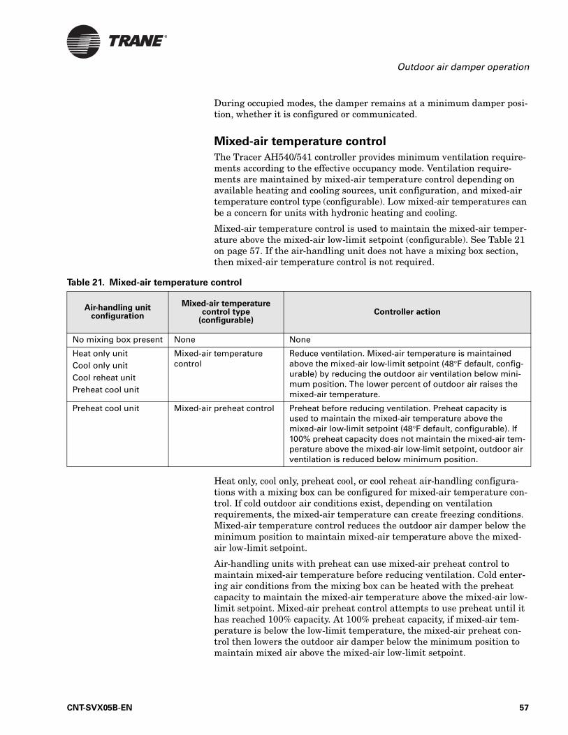
Outdoor air damper operation
During occupied modes, the damper remains at a minimum damper posi-tion, whether it is configured or communicated.
Mixed-air temperature control
The Tracer AH540/541 controller provides minimum ventilation require-ments according to the effective occupancy mode. Ventilation require-ments are maintained by mixed-air temperature control depending on available heating and cooling sources, unit configuration, and mixed-air temperature control type (configurable). Low mixed-air temperatures can be a concern for units with hydronic heating and cooling.
Mixed-air temperature control is used to maintain the mixed-air temper-ature above the mixed-air low-limit setpoint (configurable). See Table 21 on page 57. If the air-handling unit does not have a mixing box section, then mixed-air temperature control is not required.
Heat only, cool only, preheat cool, or cool reheat air-handling configura-tions with a mixing box can be configured for mixed-air temperature con-trol. If cold outdoor air conditions exist, depending on ventilation requirements, the mixed-air temperature can create freezing conditions. Mixed-air temperature control reduces the outdoor air damper below the minimum position to maintain mixed-air temperature above the mixed-air low-limit setpoint.
Air-handling units with preheat can use mixed-air preheat control to maintain mixed-air temperature before reducing ventilation. Cold enter-ing air conditions from the mixing box can be heated with the preheat capacity to maintain the mixed-air temperature above the mixed-air low-limit setpoint. Mixed-air preheat control attempts to use preheat until it has reached 100% capacity. At 100% preheat capacity, if mixed-air tem-perature is below the low-limit temperature, the mixed-air preheat con-trol then lowers the outdoor air damper below the minimum position to maintain mixed air above the mixed-air low-limit setpoint.
Table 21. Mixed-air temperature control
Air-handling unit configuration
Mixed-air temperature control type
(configurable)Controller action
No mixing box present None None
Heat only unitCool only unitCool reheat unitPreheat cool unit
Mixed-air temperature control
Reduce ventilation. Mixed-air temperature is maintained above the mixed-air low-limit setpoint (48°F default, config-urable) by reducing the outdoor air ventilation below mini-mum position. The lower percent of outdoor air raises the mixed-air temperature.
Preheat cool unit Mixed-air preheat control Preheat before reducing ventilation. Preheat capacity is used to maintain the mixed-air temperature above the mixed-air low-limit setpoint (48°F default, configurable). If 100% preheat capacity does not maintain the mixed-air tem-perature above the mixed-air low-limit setpoint, outdoor air ventilation is reduced below minimum position.
CNT-SVX05B-EN 57
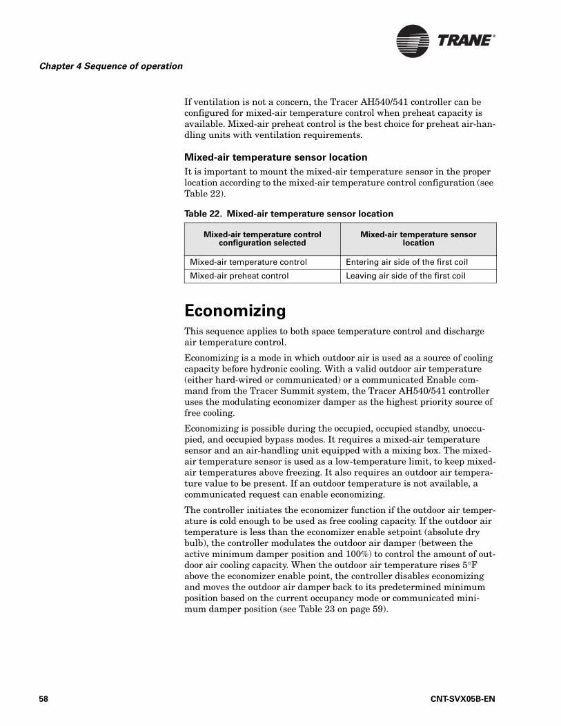
Chapter 4 Sequence of operation
If ventilation is not a concern, the Tracer AH540/541 controller can be configured for mixed-air temperature control when preheat capacity is available. Mixed-air preheat control is the best choice for preheat air-han-dling units with ventilation requirements.
Mixed-air temperature sensor location
It is important to mount the mixed-air temperature sensor in the proper location according to the mixed-air temperature control configuration (see Table 22).
EconomizingThis sequence applies to both space temperature control and discharge air temperature control.
Economizing is a mode in which outdoor air is used as a source of cooling capacity before hydronic cooling. With a valid outdoor air temperature (either hard-wired or communicated) or a communicated Enable com-mand from the Tracer Summit system, the Tracer AH540/541 controller uses the modulating economizer damper as the highest priority source of free cooling.
Economizing is possible during the occupied, occupied standby, unoccu-pied, and occupied bypass modes. It requires a mixed-air temperature sensor and an air-handling unit equipped with a mixing box. The mixed-air temperature sensor is used as a low-temperature limit, to keep mixed-air temperatures above freezing. It also requires an outdoor air tempera-ture value to be present. If an outdoor temperature is not available, a communicated request can enable economizing.
The controller initiates the economizer function if the outdoor air temper-ature is cold enough to be used as free cooling capacity. If the outdoor air temperature is less than the economizer enable setpoint (absolute dry bulb), the controller modulates the outdoor air damper (between the active minimum damper position and 100%) to control the amount of out-door air cooling capacity. When the outdoor air temperature rises 5°F above the economizer enable point, the controller disables economizing and moves the outdoor air damper back to its predetermined minimum position based on the current occupancy mode or communicated mini-mum damper position (see Table 23 on page 59).
Table 22. Mixed-air temperature sensor location
Mixed-air temperature control configuration selected
Mixed-air temperature sensor location
Mixed-air temperature control Entering air side of the first coil
Mixed-air preheat control Leaving air side of the first coil
58 CNT-SVX05B-EN
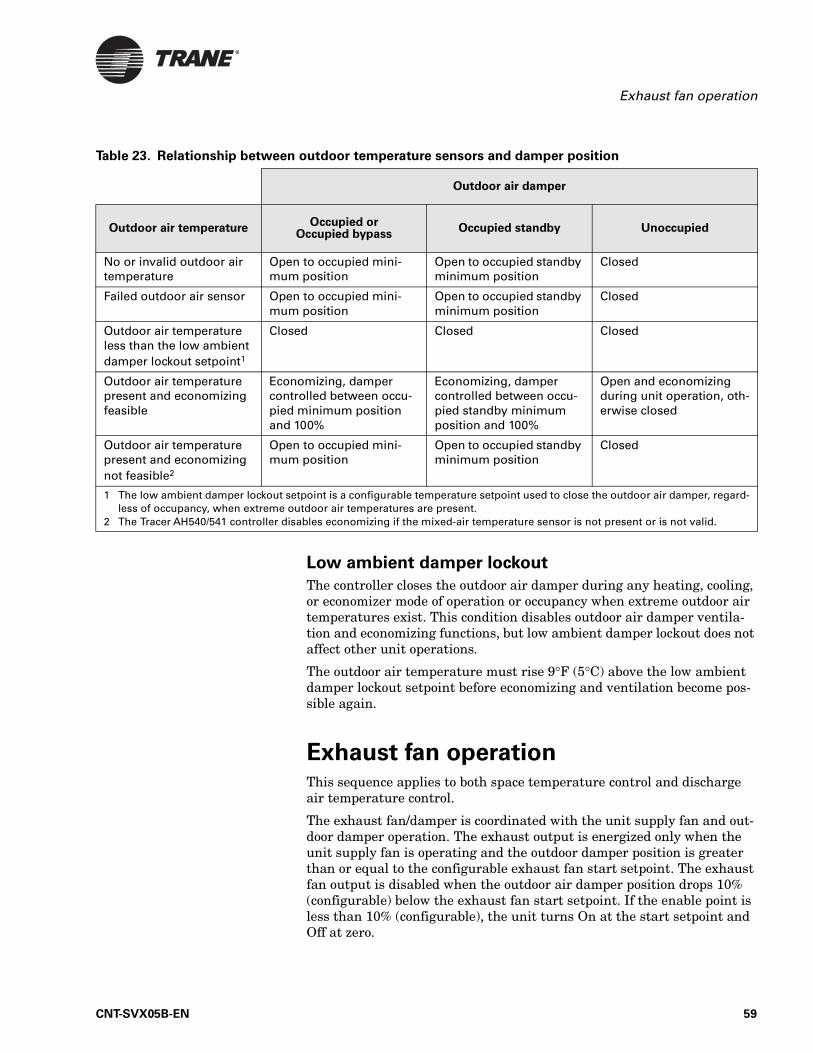
Exhaust fan operation
Low ambient damper lockout
The controller closes the outdoor air damper during any heating, cooling, or economizer mode of operation or occupancy when extreme outdoor air temperatures exist. This condition disables outdoor air damper ventila-tion and economizing functions, but low ambient damper lockout does not affect other unit operations.
The outdoor air temperature must rise 9°F (5°C) above the low ambient damper lockout setpoint before economizing and ventilation become pos-sible again.
Exhaust fan operation This sequence applies to both space temperature control and discharge air temperature control.
The exhaust fan/damper is coordinated with the unit supply fan and out-door damper operation. The exhaust output is energized only when the unit supply fan is operating and the outdoor damper position is greater than or equal to the configurable exhaust fan start setpoint. The exhaust fan output is disabled when the outdoor air damper position drops 10% (configurable) below the exhaust fan start setpoint. If the enable point is less than 10% (configurable), the unit turns On at the start setpoint and Off at zero.
Table 23. Relationship between outdoor temperature sensors and damper position
Outdoor air damper
Outdoor air temperatureOccupied or
Occupied bypassOccupied standby Unoccupied
No or invalid outdoor air temperature
Open to occupied mini-mum position
Open to occupied standby minimum position
Closed
Failed outdoor air sensor Open to occupied mini-mum position
Open to occupied standby minimum position
Closed
Outdoor air temperature less than the low ambient damper lockout setpoint1
Closed Closed Closed
Outdoor air temperature present and economizing feasible
Economizing, damper controlled between occu-pied minimum position and 100%
Economizing, damper controlled between occu-pied standby minimum position and 100%
Open and economizing during unit operation, oth-erwise closed
Outdoor air temperature present and economizing not feasible2
Open to occupied mini-mum position
Open to occupied standby minimum position
Closed
1 The low ambient damper lockout setpoint is a configurable temperature setpoint used to close the outdoor air damper, regard-less of occupancy, when extreme outdoor air temperatures are present.
2 The Tracer AH540/541 controller disables economizing if the mixed-air temperature sensor is not present or is not valid.
CNT-SVX05B-EN 59
Chapter 4 Sequence of operation
The controller logic commands the exhaust fan to be energized/de-ener-gized based on the target position of the economizing damper. Because of device stroke time, the state of the exhaust fan may change before the economizing damper reaches its target position.
If the exhaust fan start setpoint is set at or lower than the outdoor air damper minimum position, the exhaust fan will be On continuously when the outdoor air damper is at minimum position.
If the exhaust fan start setpoint is set higher than the outdoor air damper minimum position (minimum ventilation) the exhaust fan will be Off dur-ing periods of minimum ventilation. During economizer cooling operation the exhaust fan start setpoint can be selected to compensate for the increased outdoor ventilation.
The exhaust fan status binary input is present to detect operation of a belt-driven exhaust fan. An Exhaust Fan Air Flow diagnostic is detected when the control starts the exhaust fan and the exhaust fan status binary input does not indicate operation after two minutes. This is an exhaust fan latching diagnostic and discontinues exhaust operation until the diag-nostic is reset. All other control functions continue to operate normally.
Electric heat operationThis sequence applies to both space temperature control and discharge air temperature control, with differences as noted.
The Tracer AH540/541 supports two methods of controlling staged elec-tric heat:
• Staged electric heat using binary outputs.• Staged electric heat using a sequencer
For details, see “Staged electric heat” on page 61.
Electric heat operation can produce high discharge air temperatures if the unit air flow rate is low or the entering air temperature is high. The controller provides an electric heat discharge high limit control in addi-tion to functional and safety limits of the product. In draw-through unit configurations in which the electric heat source is positioned before the supply fan in the air stream, the discharge air temperature is limited to 115°F (default). Blow-through electric heat unit configurations allow a discharge-air-control high limit of 135°F (see Table 44 on page 79).
The Tracer AH540/541 controller supports only unit configurations with one source of heating capacity, with the exception of a two-pipe changeover unit with electric heat, if the controller is configured for space temperature control (see “Two-pipe changeover” on page 53). When hydronic-heating capacity is available, electric heat operation is disabled. If hydronic-heating capacity is not available, electric heat is enabled.
Electric heat is normally disabled during:
• Hydronic heating (two-pipe changeover unit)• Building automation system mechanical heating lockout is active
60 CNT-SVX05B-EN
Electric heat operation
• Cooling modes of operation (except dehumidification)• Anytime the supply fan is Off
Electric heat operation is restricted to heating modes of operation. When staged electric heat is mounted in preheat position (before cooling capac-ity), the controller will not allow the use of electric heat for mixed-air pre-heat control. If mixed-air temperature control is desired because of installed hydronic capacity, mixed-air temperature control should be used rather than mixed-air preheat control.
Space temperature control: Electric heat
For space temperature control applications, the Tracer AH540/541 per-forms cascade space temperature control and stages electric heat capacity up and down based on the discharge air temperature and discharge air temperature setpoint.
Discharge air temperature control: Electric heat
For discharge air temperature control with variable-air-volume fan opera-tion, the Tracer AH540/541 provides electric heat operation only with the following sequences:
• Morning warm-up• Daytime warm-up• Unoccupied mode
If one of these sequences is initiated, the VAV boxes are controlled to their fully open position or to the maximum air flow setpoint. The controller responds by modulating the supply fan speed to maintain the duct static pressure at the duct static pressure setpoint (see “Variable-air-volume supply fan operation: Duct static pressure” on page 51).
The controller will delay electric heat operation for the maximum heat delay time (4 minutes default, configurable). Because duct static pressure control is always maintained, maximum heat delay allows time for the VAV boxes to fully open and allows the air handler to establish full air-flow before electric heat operation begins.
Staged electric heat
The controller stages the heaters On sequentially, adding 1 stage every 2 minutes. In the unoccupied heating mode, the supply fan will delay turn-ing Off for 120 seconds after electric heat capacity stages Off to remove residual heat.
The controller supports two methods of controlling staged electric heat:
• Staged electric heat using binary outputs• Staged electric heat using a sequencer
Staged electric heat using binary outputs
One to four electric heat stages can be directly controlled from binary out-puts. Since the controller binary outputs can also be configured for stages
CNT-SVX05B-EN 61
Chapter 4 Sequence of operation
of DX cooling the binary outputs are assigned as follows where the num-ber of electric heat stages plus the number of DX cooling stages cannot exceed four outputs.
• BO3: DX cooling stage 1 or Electric heat stage 4• BO4: DX cooling stage 2 or Electric heat stage 3• BO5: DX cooling stage 3 or Electric heat stage 2• BO6: DX cooling stage 4 or Electric heat stage 1
Staged electric heat using a sequencer
Analog output AO3 can be configured to control an electric heat sequencer. This option fixes the AO3 output configuration at 0–10 Vdc, normally closed. The sequencer discrete binary outputs control the elec-tric heat stages. The AO3 signal will step according to the configured sequencer control thresholds, the number of stages installed, and to the number of stages to be energized. See Table 30 on page 74.
For example, if the controller is configured for electric heat sequencer and six heat stages, connect the step controller to analog output AO3 accord-ing to device-specific wiring instructions.
For this example, configure the Tracer AH540/541 controller as follows:
• AO3: Electric Heat (Sequencer)• Number of electric heat stages: 6• Electric heat sequencer control: default values (see Table 30 on
page 74)
Care should be taken to match the sequencer characteristics to the Tracer AH540/541 configuration. The controller will step AO3 according to the defined configuration. Figure 12 illustrates the default operation for a six-stage electric heat sequencer configuration. Table 24 on page 63 shows staging characteristics for a common, off-the-shelf, sequencer with one to six stages. According to the table, the sequencer requires a mini-mum input of 5.21 Vdc to turn On the third stage. Analog output AO3 will output 6 Vdc to energize the third stage of the sequencer, default configu-ration.
62 CNT-SVX05B-EN
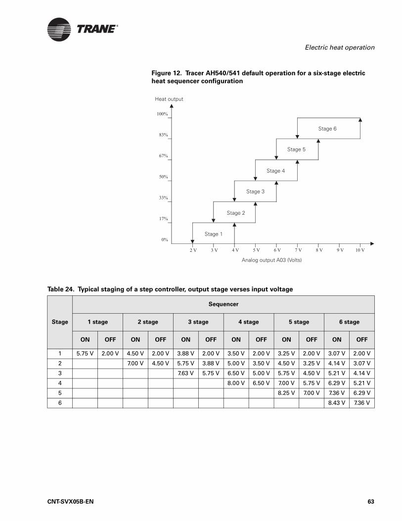
Electric heat operation
Figure 12. Tracer AH540/541 default operation for a six-stage electric
heat sequencer configuration
Table 24. Typical staging of a step controller, output stage verses input voltage
Stage
Sequencer
1 stage 2 stage 3 stage 4 stage 5 stage 6 stage
ON OFF ON OFF ON OFF ON OFF ON OFF ON OFF
1 5.75 V 2.00 V 4.50 V 2.00 V 3.88 V 2.00 V 3.50 V 2.00 V 3.25 V 2.00 V 3.07 V 2.00 V
2 7.00 V 4.50 V 5.75 V 3.88 V 5.00 V 3.50 V 4.50 V 3.25 V 4.14 V 3.07 V
3 7.63 V 5.75 V 6.50 V 5.00 V 5.75 V 4.50 V 5.21 V 4.14 V
4 8.00 V 6.50 V 7.00 V 5.75 V 6.29 V 5.21 V
5 8.25 V 7.00 V 7.36 V 6.29 V
6 8.43 V 7.36 V
CNT-SVX05B-EN 63
Chapter 4 Sequence of operation
DX cooling operationThis sequence applies to both space temperature control and discharge air temperature control.
The Tracer AH540/541 controller provides four DX cooling binary outputs to control up to four stages of cooling. A cascade control algorithm is used for space temperature control. Valid discharge air temperature sensor and space temperature sensor inputs are required for operation. As space temperature rises above the cooling setpoint, it creates a demand for more discharge-air cooling capacity. Discharge air temperature control directly controls DX cooling to provide discharge air temperature at the desired discharge-air cooling setpoint.
Anytime the discharge air temperature drops below the discharge-air low-limit setpoint (45°F, configurable) DX cooling capacity is reduced to prevent low discharge air temperatures.
DX cooling operation will be suspended if the outdoor air temperature falls below the compressor lockout temperature setpoint (50°F default, configurable). DX cooling will automatically resume when the outdoor air temperature is greater than the compressor lockout temperature plus 5°F. DX cooling can also be suspended by communicated mechanical cool-ing lockout command from a building automation system. DX cooling will remain disabled until the mechanical cooling lockout is released.
DX cooling can be coordinated with economizer operation by adjusting the Economizer Enable Temperature (60°F, default). Given the default set-points for DX cooling and economizer operation based on outdoor air tem-perature, DX and economizer operation will be initiated when outdoor air temperature falls below 60°F. DX cooling will be disabled below 50°F out-door air temperature and economizing will be disabled above 65°F out-door air temperature.
When outdoor air temperature is less than 50°F DX cooling operation will be disabled. When outdoor air temperature rises above 65°F, economizer operation is disabled.
DX cooling is normally disabled if:
• System mechanical cooling lockout is active• Outside air temperature is less than compressor cooling lockout set-
point• Defrost condition exists• Supply fan is Off
64 CNT-SVX05B-EN
DX cooling operation
Staged DX cooling
One to four DX cooling stages can be directly controlled from binary out-puts. Since the controller binary outputs can also be configured for stages of electric heat the binary outputs are assigned as follows where the num-ber of DX cooling stages plus the number of electric heat stages cannot exceed four outputs.
• BO3: DX cooling stage 1 or Electric heat stage 4• BO4: DX cooling stage 2 or Electric heat stage 3• BO5: DX cooling stage 3 or Electric heat stage 2• BO6: DX cooling stage 4 or Electric heat stage 1
The controller will enforce a minimum On time and minimum Off time for each compressor stage. A compressor will not be allowed to stage On until the compressor minimum Off time has expired and a compressor will not be allowed to stage Of until the compressor minimum On time has expired. See Table 39 on page 77.
Inter-stage delays are also enforced. A minimum of 3 minutes will be enforced between additional cooling stages. A minimum of 2 minutes will be enforced between subtracting cooling stages.
Defrost operation
Low evaporator refrigerant temperatures can cause the coil to frost. The Tracer AH540/541 controller provides two methods of detecting low evap-orator refrigerant temperatures:
• One uses the evaporator refrigerant temperature (analog input IN13) to measure suction temperature
• The other uses a binary thermostat device (binary input IN7 or IN12) applied to the evaporator suction line
Two-circuit split-system DX cooling applications should provide an evapo-rator refrigerant sensor or binary thermostat device on the first circuit or the circuit with the first cooling stage. As an option, both an evaporator refrigerant sensor and binary thermostat can be used on a unit with one device installed on each circuit. The controller will respond according to either frost input.
Two binary thermostat devices can also be used with one device installed on each circuit. The devices are separately hard-wired to coil defrost inputs IN7 and IN12, or the thermostat devices are wired in series to coil defrost input IN7 or IN12.
Evaporator refrigerant temperature
A 10 kΩ thermistor can be hard-wired to the universal analog input IN13. The controller has the ability to directly measure the evaporator refriger-ant temperature. If evaporator refrigerant temperature drops below the defrost setpoint (30°F, default) the controller will unload one compressor stage every 120 seconds. If the refrigerant temperature rises above the defrost setpoint, DX cooling will stop unloading and each stage that frosted will be enabled after a minimum of 10 minutes. If the refrigerant
CNT-SVX05B-EN 65
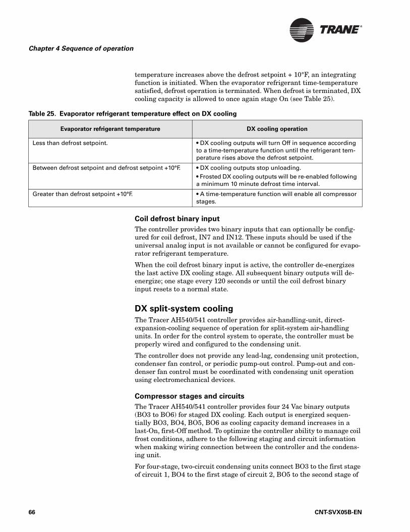
Chapter 4 Sequence of operation
temperature increases above the defrost setpoint + 10°F, an integrating function is initiated. When the evaporator refrigerant time-temperature satisfied, defrost operation is terminated. When defrost is terminated, DX cooling capacity is allowed to once again stage On (see Table 25).
Coil defrost binary input
The controller provides two binary inputs that can optionally be config-ured for coil defrost, IN7 and IN12. These inputs should be used if the universal analog input is not available or cannot be configured for evapo-rator refrigerant temperature.
When the coil defrost binary input is active, the controller de-energizes the last active DX cooling stage. All subsequent binary outputs will de-energize; one stage every 120 seconds or until the coil defrost binary input resets to a normal state.
DX split-system cooling
The Tracer AH540/541 controller provides air-handling-unit, direct-expansion-cooling sequence of operation for split-system air-handling units. In order for the control system to operate, the controller must be properly wired and configured to the condensing unit.
The controller does not provide any lead-lag, condensing unit protection, condenser fan control, or periodic pump-out control. Pump-out and con-denser fan control must be coordinated with condensing unit operation using electromechanical devices.
Compressor stages and circuits
The Tracer AH540/541 controller provides four 24 Vac binary outputs (BO3 to BO6) for staged DX cooling. Each output is energized sequen-tially BO3, BO4, BO5, BO6 as cooling capacity demand increases in a last-On, first-Off method. To optimize the controller ability to manage coil frost conditions, adhere to the following staging and circuit information when making wiring connection between the controller and the condens-ing unit.
For four-stage, two-circuit condensing units connect BO3 to the first stage of circuit 1, BO4 to the first stage of circuit 2, BO5 to the second stage of
Table 25. Evaporator refrigerant temperature effect on DX cooling
Evaporator refrigerant temperature DX cooling operation
Less than defrost setpoint. • DX cooling outputs will turn Off in sequence according to a time-temperature function until the refrigerant tem-perature rises above the defrost setpoint.
Between defrost setpoint and defrost setpoint +10°F. • DX cooling outputs stop unloading.• Frosted DX cooling outputs will be re-enabled following a minimum 10 minute defrost time interval.
Greater than defrost setpoint +10°F. • A time-temperature function will enable all compressor stages.
66 CNT-SVX05B-EN
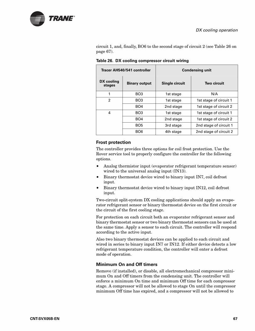
DX cooling operation
circuit 1, and, finally, BO6 to the second stage of circuit 2 (see Table 26 on page 67).
Frost protection
The controller provides three options for coil frost protection. Use the Rover service tool to properly configure the controller for the following options.
• Analog thermistor input (evaporator refrigerant temperature sensor) wired to the universal analog input (IN13).
• Binary thermostat device wired to binary input IN7, coil defrost input.
• Binary thermostat device wired to binary input IN12, coil defrost input.
Two-circuit split-system DX cooling applications should apply an evapo-rator refrigerant sensor or binary thermostat device on the first circuit or the circuit of the first cooling stage.
For protection on each circuit both an evaporator refrigerant sensor and binary thermostat sensor or two binary thermostat sensors can be used at the same time. Apply a sensor to each circuit. The controller will respond according to the active input.
Also two binary thermostat devices can be applied to each circuit and wired in series to binary input IN7 or IN12. If either device detects a low refrigerant temperature condition, the controller will enter a defrost mode of operation.
Minimum On and Off timers
Remove (if installed), or disable, all electromechanical compressor mini-mum On and Off timers from the condensing unit. The controller will enforce a minimum On time and minimum Off time for each compressor stage. A compressor will not be allowed to stage On until the compressor minimum Off time has expired, and a compressor will not be allowed to
Table 26. DX cooling compressor circuit wiring
Tracer AH540/541 controller Condensing unit
DX cooling stages
Binary output Single circuit Two circuit
1 BO3 1st stage N/A
2 BO3 1st stage 1st stage of circuit 1
BO4 2nd stage 1st stage of circuit 2
4 BO3 1st stage 1st stage of circuit 1
BO4 2nd stage 1st stage of circuit 2
BO5 3rd stage 2nd stage of circuit 1
BO6 4th stage 2nd stage of circuit 2
CNT-SVX05B-EN 67
Chapter 4 Sequence of operation
stage Off until the compressor minimum On time has expired (see Table 39 on page 77).
Neglecting to remove or disable the electromechanical timers will cause the compressor operation to lose coordination with the controller com-pressor staging control, and will result in poor control performance.
DehumidificationThis sequence applies only to space temperature control.
The Tracer AH540/541 controller provides both occupied and unoccupied dehumidification control when cooling and reheat capacity is available. The dehumidification control sequence is allowed on unit configurations with hydronic or DX cooling and hydronic or electric reheat.
Both occupied and unoccupied space humidity setpoints are provided as well as setpoint offset values (10% default) to terminate dehumidification mode. To disable occupied space dehumidification, set the Occupied Space RH setpoint to 0%. Likewise, to disable unoccupied space dehumidifica-tion, set the Unoccupied Space RH setpoint to 0%. Use the Rover service tool to edit these setpoints.
Space dehumidification requires a space relative humidity sensor input hard-wired to the universal analog input IN13 or a communicated RH value. If both a hard-wired relative humidity sensor and a communicated RH value is present, the communicated value will be used for dehumidifi-cation control.
Occupied and unoccupied mode dehumidification
When the space relative humidity is greater than the Occupied Space RH Setpoint, dehumidification control is initiated. The dehumidification con-trol mode will remain active until space relative humidity is less than the Occupied Space RH Setpoint minus Occupied Space RH Offset value. The controller will automatically revert back to occupied or occupied standby space temperature control.
When in unoccupied mode and the space relative humidity is greater than the Unoccupied Space RH Setpoint, dehumidification is initiated until space relative humidity is less then the Unoccupied Space RH Setpoint minus Unoccupied Space RH Offset value. The controller will automati-cally revert back to unoccupied space temperature control.
Space temperature and relative humidity are both controlled when dehu-midification is active. Cooling capacity is modulated or staged to reduce space humidity, while heating capacity is modulated or staged to control space temperature. Hydronic cooling capacity is modulated (increased and decreased) to offset the relative humidity load in the space. DX cool-ing capacity operates as a limit control and is only allowed to stage up (increase) to maintain or decrease the relative humidity in the space.
68 CNT-SVX05B-EN
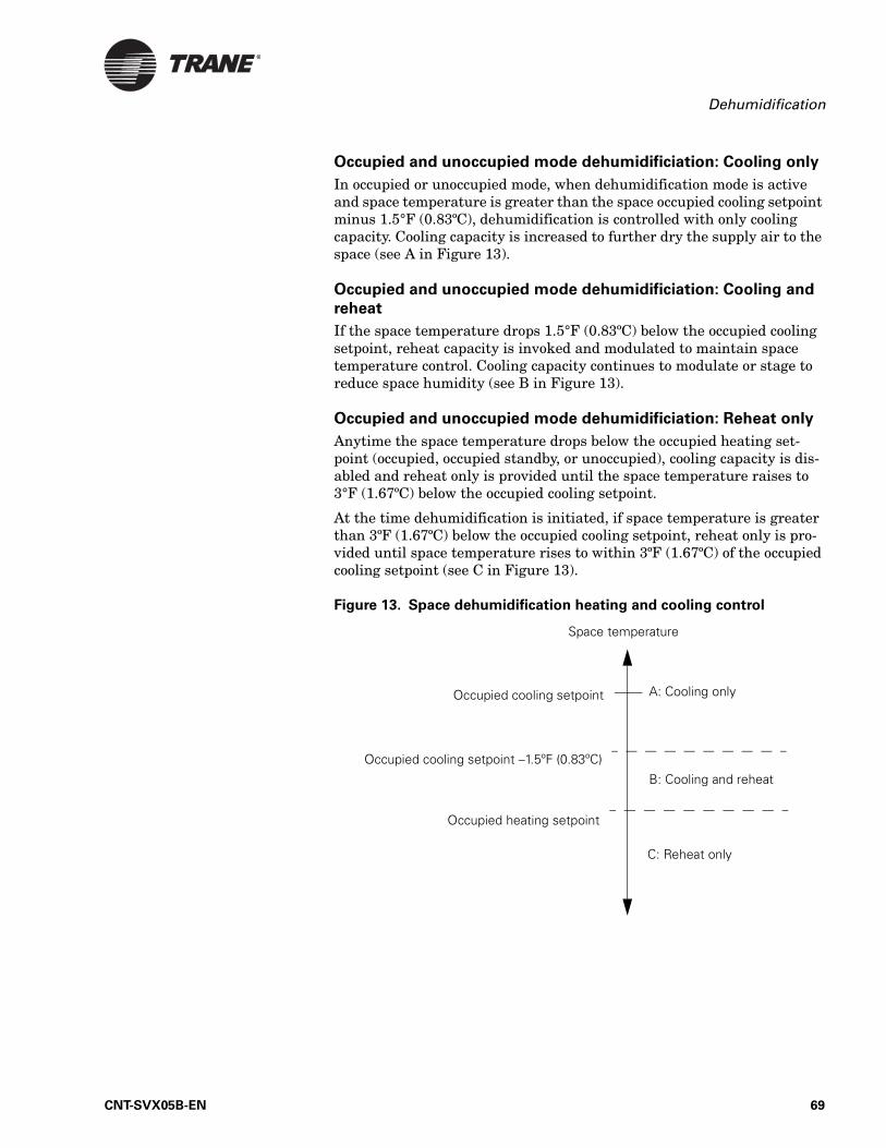
Dehumidification
Occupied and unoccupied mode dehumidificiation: Cooling only
In occupied or unoccupied mode, when dehumidification mode is active and space temperature is greater than the space occupied cooling setpoint minus 1.5°F (0.83ºC), dehumidification is controlled with only cooling capacity. Cooling capacity is increased to further dry the supply air to the space (see A in Figure 13).
Occupied and unoccupied mode dehumidificiation: Cooling and
reheat
If the space temperature drops 1.5°F (0.83ºC) below the occupied cooling setpoint, reheat capacity is invoked and modulated to maintain space temperature control. Cooling capacity continues to modulate or stage to reduce space humidity (see B in Figure 13).
Occupied and unoccupied mode dehumidificiation: Reheat only
Anytime the space temperature drops below the occupied heating set-point (occupied, occupied standby, or unoccupied), cooling capacity is dis-abled and reheat only is provided until the space temperature raises to 3°F (1.67ºC) below the occupied cooling setpoint.
At the time dehumidification is initiated, if space temperature is greater than 3ºF (1.67ºC) below the occupied cooling setpoint, reheat only is pro-vided until space temperature rises to within 3ºF (1.67ºC) of the occupied cooling setpoint (see C in Figure 13).
Figure 13. Space dehumidification heating and cooling control
Space temperature
Occupied cooling setpoint –1.5ºF (0.83ºC)
C: Reheat only
A: Cooling only
B: Cooling and reheat
Occupied heating setpoint
Occupied cooling setpoint
CNT-SVX05B-EN 69
Chapter 4 Sequence of operation
Unit protection strategiesThe following strategies are initiated, for both space temperature control and discharge air temperature control, when specific conditions exists in order to protect the unit or building from damage:
• Run/stop binary input (see “IN8: Run/stop” on page 25)• Supply fan status (“IN10: Supply fan status” on page 26)• Condensing unit protection
— Coil defrost (see “Defrost operation” on page 65)— Compressor minimum On/Off timers (see “DX cooling operation”
on page 64)• Duct static pressure high limit (see “Variable-air-volume supply fan
operation: Duct static pressure” on page 51)• Coil freeze protection
— Face-and-bypass heating (“Face-and-bypass damper operation” on page 55)
— Freeze avoidance (see “Freeze-avoidance valve cycling” on page 52)
— Mixed-air temperature control (see “Mixed-air temperature con-trol” on page 57)
— Low-temperature detection (see “IN7: Low-temperature detection or coil defrost” on page 24)
• Supply fan motor thermal protection (see “Electric heat operation” on page 60)
• Filter status (see “Filter status” on page 70)• Freeze avoidance (see “Freeze avoidance” on page 70)
Filter status
The controller filter status is based on the supply fan cumulative run hours. The controller compares the fan run time against an adjustable fan run hours limit (maintenance required setpoint time, stored in the con-troller) and recommends unit maintenance as required. The Maintenance Required diagnostic is informational only. Its state does not affect unit operation.
Use the Rover service tool to edit the Maintenance Required setpoint time. When the setpoint limit is exceeded, the controller generates a Maintenance Required diagnostic. To disable the diagnostic feature, set the maintenance required setpoint time to zero.
You can use Rover service tool or Tracer Summit to clear the Maintenance Required diagnostic. When the diagnostic is cleared, the controller resets the fan run time to zero and resumes accumulating fan run hours.
Freeze avoidance
Freeze avoidance is used as low ambient temperature protection and is only initiated anytime the supply fan is Off. The controller enters the freeze avoidance mode when the outdoor air temperature is below the
70 CNT-SVX05B-EN
Overrides
freeze avoidance setpoint (configurable). The controller disables freeze avoidance when the outdoor air temperature rises 3°F (1.67ºC) above the freeze avoidance setpoint. When the controller is in freeze avoidance mode:
• All water valves are driven open to allow water to flow through the coil
• Steam and hydronic heat valves are cycled open and closed to prevent excessive cabinet temperatures
• Supply fan is Off• Face-and-bypass damper (when present) is at full bypass
Freeze avoidance protects the air-handling unit hydronic heating and cooling coils from freezing when cold outdoor air temperatures are present and the supply fan is Off. For example, the Tracer AH540/541 is not able to run the air-handling unit because the run/stop input is set to stop (supply fan is Off). If the outdoor air temperature is below the freeze avoidance setpoint, the Tracer AH540/541 opens all water valves.
OverridesThe controller has the capability, whether using space temperature con-trol or discharge air temperature control, to override both analog and binary output (typically for testing and commissioning) through the Tracer Summit building automation system or from the Rover service tool. For more information about the output overrides, refer to literature for those products.
In addition, AH540/541 override capability include:
• Manual output test• Emergency override• Water valve override
Manual output test
The controller includes a manual output test function, which allows the user to manually exercise the outputs in a predefined sequence using the Test push button (see “Performing a manual output test” on page 84). You can also perform the manual output test remotely using the Rover service tool. The Rover service tool communications through the Comm5 link to place the controller in service override mode. From the Rover computer screen you can step the controller through the manual output test.
Emergency override
The Tracer AH540/541 controller can be placed into emergency override by using the communication variable (nviEmergOverride). Emergency override allows a building automation system such as Trane Tracer Sum-mit to pressurize, depressurize, or purge the air from a building space. It can also be used to shut down the controller operation of the unit.
CNT-SVX05B-EN 71
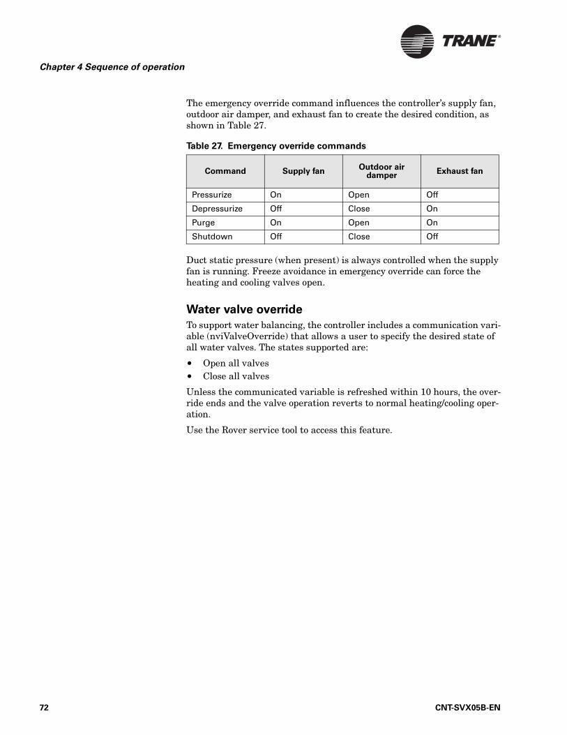
Chapter 4 Sequence of operation
The emergency override command influences the controller’s supply fan, outdoor air damper, and exhaust fan to create the desired condition, as shown in Table 27.
Duct static pressure (when present) is always controlled when the supply fan is running. Freeze avoidance in emergency override can force the heating and cooling valves open.
Water valve override
To support water balancing, the controller includes a communication vari-able (nviValveOverride) that allows a user to specify the desired state of all water valves. The states supported are:
• Open all valves• Close all valves
Unless the communicated variable is refreshed within 10 hours, the over-ride ends and the valve operation reverts to normal heating/cooling oper-ation.
Use the Rover service tool to access this feature.
Table 27. Emergency override commands
Command Supply fanOutdoor air
damperExhaust fan
Pressurize On Open Off
Depressurize Off Close On
Purge On Open On
Shutdown Off Close Off
72 CNT-SVX05B-EN
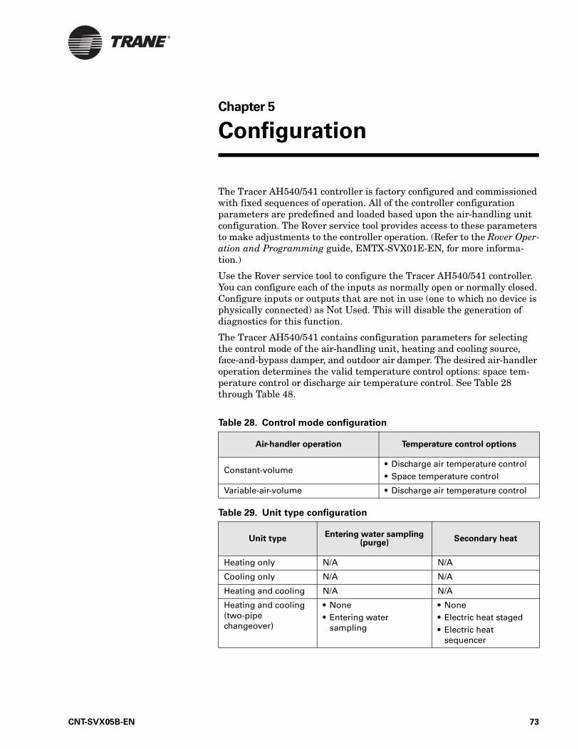
Chapter 5
Configuration
The Tracer AH540/541 controller is factory configured and commissioned with fixed sequences of operation. All of the controller configuration parameters are predefined and loaded based upon the air-handling unit configuration. The Rover service tool provides access to these parameters to make adjustments to the controller operation. (Refer to the Rover Oper-ation and Programming guide, EMTX-SVX01E-EN, for more informa-tion.)
Use the Rover service tool to configure the Tracer AH540/541 controller. You can configure each of the inputs as normally open or normally closed. Configure inputs or outputs that are not in use (one to which no device is physically connected) as Not Used. This will disable the generation of diagnostics for this function.
The Tracer AH540/541 contains configuration parameters for selecting the control mode of the air-handling unit, heating and cooling source, face-and-bypass damper, and outdoor air damper. The desired air-handler operation determines the valid temperature control options: space tem-perature control or discharge air temperature control. See Table 28 through Table 48.
Table 28. Control mode configuration
Air-handler operation Temperature control options
Constant-volume• Discharge air temperature control• Space temperature control
Variable-air-volume • Discharge air temperature control
Table 29. Unit type configuration
Unit typeEntering water sampling
(purge)Secondary heat
Heating only N/A N/A
Cooling only N/A N/A
Heating and cooling N/A N/A
Heating and cooling (two-pipe changeover)
• None• Entering water
sampling
• None• Electric heat staged• Electric heat
sequencer
CNT-SVX05B-EN 73
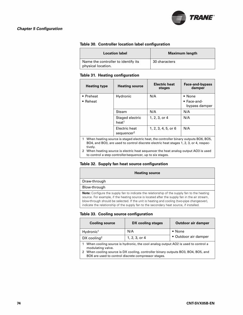
Chapter 5 Configuration
Table 30. Controller location label configuration
Location label Maximum length
Name the controller to identify its physical location.
30 characters
Table 31. Heating configuration
Heating type Heating sourceElectric heat
stagesFace-and-bypass
damper
• Preheat• Reheat
Hydronic N/A • None• Face-and-
bypass damper
Steam N/A N/A
Staged electric heat1
1, 2, 3, or 4 N/A
Electric heat sequencer2
1, 2, 3, 4, 5, or 6 N/A
1 When heating source is staged electric heat, the controller binary outputs BO6, BO5, BO4, and BO3, are used to control discrete electric heat stages 1, 2, 3, or 4, respec-tively.
2 When heating source is electric heat sequencer the heat analog output AO3 is used to control a step controller/sequencer, up to six stages.
Table 32. Supply fan heat source configuration
Heating source
Draw-through
Blow-through
Note: Configure the supply fan to indicate the relationship of the supply fan to the heating source. For example, if the heating source is located after the supply fan in the air stream, blow-through should be selected. If the unit is heating and cooling (two-pipe changeover), indicate the relationship of the supply fan to the secondary heat source, if installed.
Table 33. Cooling source configuration
Cooling source DX cooling stages Outdoor air damper
Hydronic1 N/A • None• Outdoor air damperDX cooling2 1, 2, 3, or 4
1 When cooling source is hydronic, the cool analog output AO2 is used to control a modulating valve.
2 When cooling source is DX cooling, controller binary outputs BO3, BO4, BO5, and BO6 are used to control discrete compressor stages.
74 CNT-SVX05B-EN
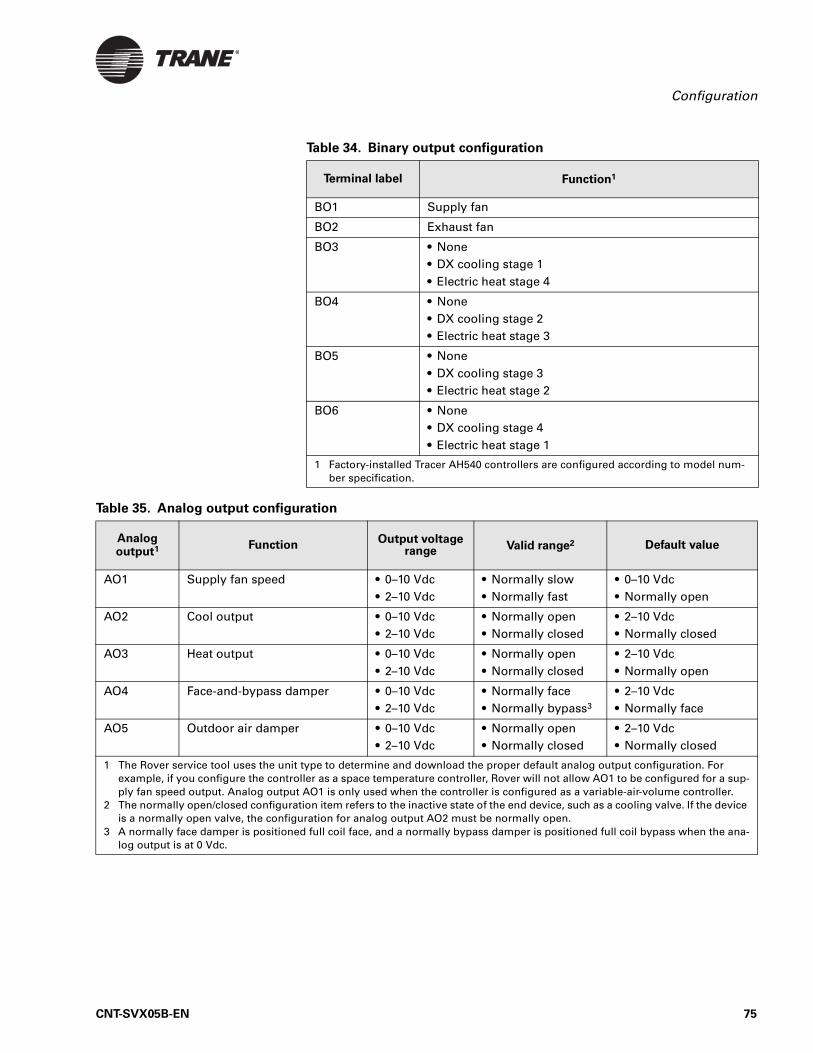
Configuration
Table 34. Binary output configuration
Terminal label Function1
BO1 Supply fan
BO2 Exhaust fan
BO3 • None• DX cooling stage 1• Electric heat stage 4
BO4 • None• DX cooling stage 2• Electric heat stage 3
BO5 • None• DX cooling stage 3• Electric heat stage 2
BO6 • None• DX cooling stage 4• Electric heat stage 1
1 Factory-installed Tracer AH540 controllers are configured according to model num-ber specification.
Table 35. Analog output configuration
Analog output1 Function
Output voltage range Valid range2 Default value
AO1 Supply fan speed • 0–10 Vdc• 2–10 Vdc
• Normally slow• Normally fast
• 0–10 Vdc• Normally open
AO2 Cool output • 0–10 Vdc• 2–10 Vdc
• Normally open• Normally closed
• 2–10 Vdc• Normally closed
AO3 Heat output • 0–10 Vdc• 2–10 Vdc
• Normally open• Normally closed
• 2–10 Vdc• Normally open
AO4 Face-and-bypass damper • 0–10 Vdc• 2–10 Vdc
• Normally face• Normally bypass3
• 2–10 Vdc• Normally face
AO5 Outdoor air damper • 0–10 Vdc• 2–10 Vdc
• Normally open• Normally closed
• 2–10 Vdc• Normally closed
1 The Rover service tool uses the unit type to determine and download the proper default analog output configuration. For example, if you configure the controller as a space temperature controller, Rover will not allow AO1 to be configured for a sup-ply fan speed output. Analog output AO1 is only used when the controller is configured as a variable-air-volume controller.
2 The normally open/closed configuration item refers to the inactive state of the end device, such as a cooling valve. If the device is a normally open valve, the configuration for analog output AO2 must be normally open.
3 A normally face damper is positioned full coil face, and a normally bypass damper is positioned full coil bypass when the ana-log output is at 0 Vdc.
CNT-SVX05B-EN 75
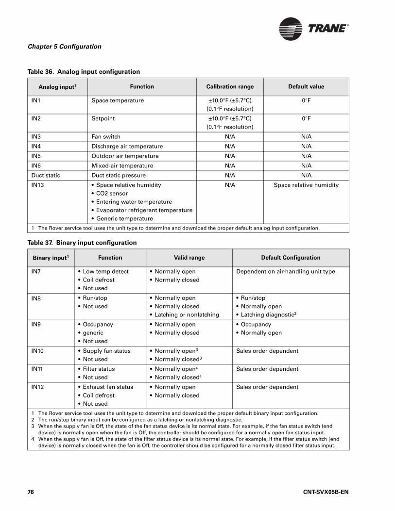
Chapter 5 Configuration
Table 36. Analog input configuration
Analog input1 Function Calibration range Default value
IN1 Space temperature ±10.0°F (±5.7°C)(0.1°F resolution)
0°F
IN2 Setpoint ±10.0°F (±5.7°C)(0.1°F resolution)
0°F
IN3 Fan switch N/A N/A
IN4 Discharge air temperature N/A N/A
IN5 Outdoor air temperature N/A N/A
IN6 Mixed-air temperature N/A N/A
Duct static Duct static pressure N/A N/A
IN13 • Space relative humidity• CO2 sensor• Entering water temperature• Evaporator refrigerant temperature• Generic temperature
N/A Space relative humidity
1 The Rover service tool uses the unit type to determine and download the proper default analog input configuration.
Table 37. Binary input configuration
Binary input1 Function Valid range Default Configuration
IN7 • Low temp detect• Coil defrost• Not used
• Normally open• Normally closed
Dependent on air-handling unit type
IN8 • Run/stop• Not used
• Normally open• Normally closed• Latching or nonlatching
• Run/stop• Normally open• Latching diagnostic2
IN9 • Occupancy• generic• Not used
• Normally open• Normally closed
• Occupancy• Normally open
IN10 • Supply fan status• Not used
• Normally open3
• Normally closed3
Sales order dependent
IN11 • Filter status• Not used
• Normally open4
• Normally closed4
Sales order dependent
IN12 • Exhaust fan status • Coil defrost• Not used
• Normally open• Normally closed
Sales order dependent
1 The Rover service tool uses the unit type to determine and download the proper default binary input configuration.2 The run/stop binary input can be configured as a latching or nonlatching diagnostic.3 When the supply fan is Off, the state of the fan status device is its normal state. For example, if the fan status switch (end
device) is normally open when the fan is Off, the controller should be configured for a normally open fan status input.4 When the supply fan is Off, the state of the filter status device is its normal state. For example, if the filter status switch (end
device) is normally closed when the fan is Off, the controller should be configured for a normally closed filter status input.
76 CNT-SVX05B-EN
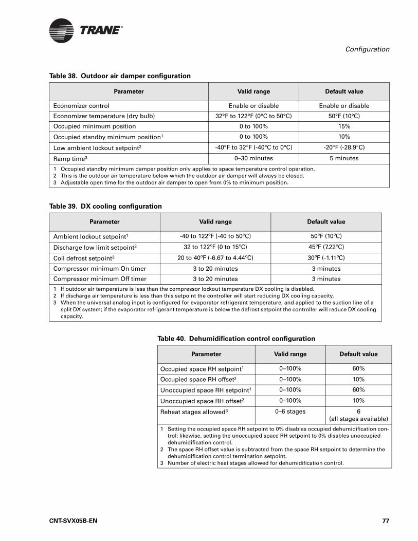
Configuration
Table 38. Outdoor air damper configuration
Parameter Valid range Default value
Economizer control Enable or disable Enable or disable
Economizer temperature (dry bulb) 32°F to 122°F (0°C to 50°C) 50°F (10°C)
Occupied minimum position 0 to 100% 15%
Occupied standby minimum position1 0 to 100% 10%
Low ambient lockout setpoint2 -40°F to 32°F (-40°C to 0°C) -20°F (-28.9°C)
Ramp time3 0–30 minutes 5 minutes
1 Occupied standby minimum damper position only applies to space temperature control operation.2 This is the outdoor air temperature below which the outdoor air damper will always be closed.3 Adjustable open time for the outdoor air damper to open from 0% to minimum position.
Table 39. DX cooling configuration
Parameter Valid range Default value
Ambient lockout setpoint1 -40 to 122ºF (-40 to 50ºC) 50ºF (10ºC)
Discharge low limit setpoint2 32 to 122ºF (0 to 15ºC) 45ºF (7.22ºC)
Coil defrost setpoint3 20 to 40ºF (-6.67 to 4.44ºC) 30ºF (-1.11ºC)
Compressor minimum On timer 3 to 20 minutes 3 minutes
Compressor minimum Off timer 3 to 20 minutes 3 minutes
1 If outdoor air temperature is less than the compressor lockout temperature DX cooling is disabled.2 If discharge air temperature is less than this setpoint the controller will start reducing DX cooling capacity.3 When the universal analog input is configured for evaporator refrigerant temperature, and applied to the suction line of a
split DX system; if the evaporator refrigerant temperature is below the defrost setpoint the controller will reduce DX cooling capacity.
Table 40. Dehumidification control configuration
Parameter Valid range Default value
Occupied space RH setpoint1 0–100% 60%
Occupied space RH offset2 0–100% 10%
Unoccupied space RH setpoint1 0–100% 60%
Unoccupied space RH offset2 0–100% 10%
Reheat stages allowed3 0–6 stages 6(all stages available)
1 Setting the occupied space RH setpoint to 0% disables occupied dehumidification con-trol; likewise, setting the unoccupied space RH setpoint to 0% disables unoccupied dehumidification control.
2 The space RH offset value is subtracted from the space RH setpoint to determine the dehumidification control termination setpoint.
3 Number of electric heat stages allowed for dehumidification control.
CNT-SVX05B-EN 77
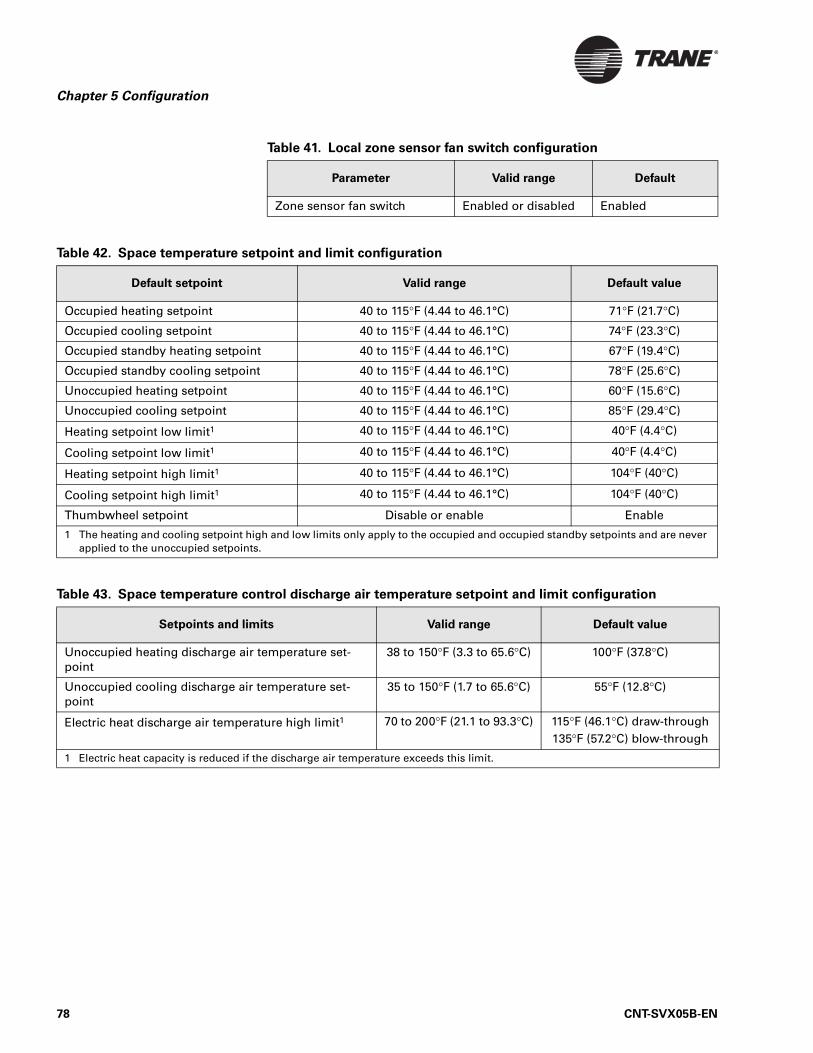
Chapter 5 Configuration
Table 41. Local zone sensor fan switch configuration
Parameter Valid range Default
Zone sensor fan switch Enabled or disabled Enabled
Table 42. Space temperature setpoint and limit configuration
Default setpoint Valid range Default value
Occupied heating setpoint 40 to 115°F (4.44 to 46.1°C) 71°F (21.7°C)
Occupied cooling setpoint 40 to 115°F (4.44 to 46.1°C) 74°F (23.3°C)
Occupied standby heating setpoint 40 to 115°F (4.44 to 46.1°C) 67°F (19.4°C)
Occupied standby cooling setpoint 40 to 115°F (4.44 to 46.1°C) 78°F (25.6°C)
Unoccupied heating setpoint 40 to 115°F (4.44 to 46.1°C) 60°F (15.6°C)
Unoccupied cooling setpoint 40 to 115°F (4.44 to 46.1°C) 85°F (29.4°C)
Heating setpoint low limit1 40 to 115°F (4.44 to 46.1°C) 40°F (4.4°C)
Cooling setpoint low limit1 40 to 115°F (4.44 to 46.1°C) 40°F (4.4°C)
Heating setpoint high limit1 40 to 115°F (4.44 to 46.1°C) 104°F (40°C)
Cooling setpoint high limit1 40 to 115°F (4.44 to 46.1°C) 104°F (40°C)
Thumbwheel setpoint Disable or enable Enable
1 The heating and cooling setpoint high and low limits only apply to the occupied and occupied standby setpoints and are never applied to the unoccupied setpoints.
Table 43. Space temperature control discharge air temperature setpoint and limit configuration
Setpoints and limits Valid range Default value
Unoccupied heating discharge air temperature set-point
38 to 150°F (3.3 to 65.6°C) 100°F (37.8°C)
Unoccupied cooling discharge air temperature set-point
35 to 150°F (1.7 to 65.6°C) 55°F (12.8°C)
Electric heat discharge air temperature high limit1 70 to 200°F (21.1 to 93.3°C) 115°F (46.1°C) draw-through135°F (57.2°C) blow-through
1 Electric heat capacity is reduced if the discharge air temperature exceeds this limit.
78 CNT-SVX05B-EN
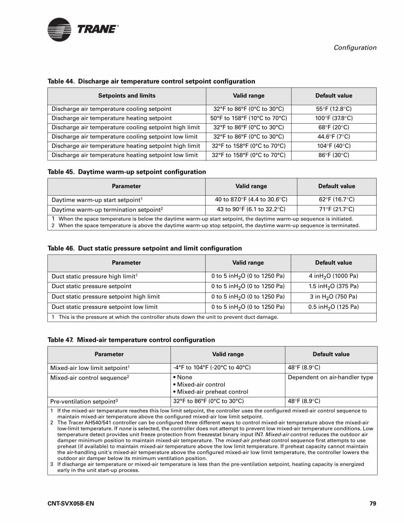
Configuration
Table 44. Discharge air temperature control setpoint configuration
Setpoints and limits Valid range Default value
Discharge air temperature cooling setpoint 32°F to 86°F (0°C to 30°C) 55°F (12.8°C)
Discharge air temperature heating setpoint 50°F to 158°F (10°C to 70°C) 100°F (37.8°C)
Discharge air temperature cooling setpoint high limit 32°F to 86°F (0°C to 30°C) 68°F (20°C)
Discharge air temperature cooling setpoint low limit 32°F to 86°F (0°C to 30°C) 44.6°F (7°C)
Discharge air temperature heating setpoint high limit 32°F to 158°F (0°C to 70°C) 104°F (40°C)
Discharge air temperature heating setpoint low limit 32°F to 158°F (0°C to 70°C) 86°F (30°C)
Table 45. Daytime warm-up setpoint configuration
Parameter Valid range Default value
Daytime warm-up start setpoint1 40 to 87.0°F (4.4 to 30.6°C) 62°F (16.7°C)
Daytime warm-up termination setpoint2 43 to 90°F (6.1 to 32.2°C) 71°F (21.7°C)
1 When the space temperature is below the daytime warm-up start setpoint, the daytime warm-up sequence is initiated.2 When the space temperature is above the daytime warm-up stop setpoint, the daytime warm-up sequence is terminated.
Table 46. Duct static pressure setpoint and limit configuration
Parameter Valid range Default value
Duct static pressure high limit1 0 to 5 inH2O (0 to 1250 Pa) 4 inH2O (1000 Pa)
Duct static pressure setpoint 0 to 5 inH2O (0 to 1250 Pa) 1.5 inH2O (375 Pa)
Duct static pressure setpoint high limit 0 to 5 inH2O (0 to 1250 Pa) 3 in H2O (750 Pa)
Duct static pressure setpoint low limit 0 to 5 inH2O (0 to 1250 Pa) 0.5 inH2O (125 Pa)
1 This is the pressure at which the controller shuts down the unit to prevent duct damage.
Table 47. Mixed-air temperature control configuration
Parameter Valid range Default value
Mixed-air low limit setpoint1 -4°F to 104°F (-20°C to 40°C) 48°F (8.9°C)
Mixed-air control sequence2 • None• Mixed-air control• Mixed-air preheat control
Dependent on air-handler type
Pre-ventilation setpoint3 32°F to 86°F (0°C to 30°C) 48°F (8.9°C)
1 If the mixed-air temperature reaches this low limit setpoint, the controller uses the configured mixed-air control sequence to maintain mixed-air temperature above the configured mixed-air low limit setpoint.
2 The Tracer AH540/541 controller can be configured three different ways to control mixed-air temperature above the mixed-air low-limit temperature. If none is selected, the controller does not attempt to prevent low mixed-air temperature conditions. Low temperature detect provides unit freeze protection from freezestat binary input IN7. Mixed-air control reduces the outdoor air damper minimum position to maintain mixed-air temperature. The mixed-air preheat control sequence first attempts to use preheat (if available) to maintain mixed-air temperature above the low limit temperature. If preheat capacity cannot maintain the air-handling unit's mixed-air temperature above the configured mixed-air low limit temperature, the controller lowers the outdoor air damper below its minimum ventilation position.
3 If discharge air temperature or mixed-air temperature is less than the pre-ventilation setpoint, heating capacity is energized early in the unit start-up process.
CNT-SVX05B-EN 79
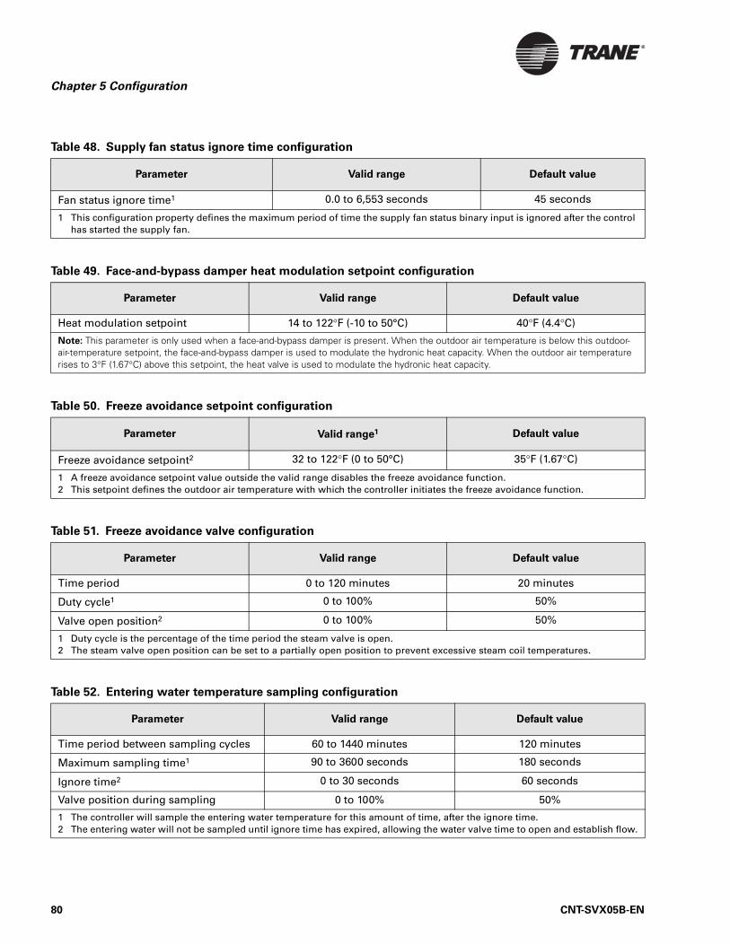
Chapter 5 Configuration
Table 48. Supply fan status ignore time configuration
Parameter Valid range Default value
Fan status ignore time1 0.0 to 6,553 seconds 45 seconds
1 This configuration property defines the maximum period of time the supply fan status binary input is ignored after the control has started the supply fan.
Table 49. Face-and-bypass damper heat modulation setpoint configuration
Parameter Valid range Default value
Heat modulation setpoint 14 to 122°F (-10 to 50°C) 40°F (4.4°C)
Note: This parameter is only used when a face-and-bypass damper is present. When the outdoor air temperature is below this outdoor-air-temperature setpoint, the face-and-bypass damper is used to modulate the hydronic heat capacity. When the outdoor air temperature rises to 3°F (1.67°C) above this setpoint, the heat valve is used to modulate the hydronic heat capacity.
Table 50. Freeze avoidance setpoint configuration
Parameter Valid range1 Default value
Freeze avoidance setpoint2 32 to 122°F (0 to 50°C) 35°F (1.67°C)
1 A freeze avoidance setpoint value outside the valid range disables the freeze avoidance function.2 This setpoint defines the outdoor air temperature with which the controller initiates the freeze avoidance function.
Table 51. Freeze avoidance valve configuration
Parameter Valid range Default value
Time period 0 to 120 minutes 20 minutes
Duty cycle1 0 to 100% 50%
Valve open position2 0 to 100% 50%
1 Duty cycle is the percentage of the time period the steam valve is open.2 The steam valve open position can be set to a partially open position to prevent excessive steam coil temperatures.
Table 52. Entering water temperature sampling configuration
Parameter Valid range Default value
Time period between sampling cycles 60 to 1440 minutes 120 minutes
Maximum sampling time1 90 to 3600 seconds 180 seconds
Ignore time2 0 to 30 seconds 60 seconds
Valve position during sampling 0 to 100% 50%
1 The controller will sample the entering water temperature for this amount of time, after the ignore time.2 The entering water will not be sampled until ignore time has expired, allowing the water valve time to open and establish flow.
80 CNT-SVX05B-EN
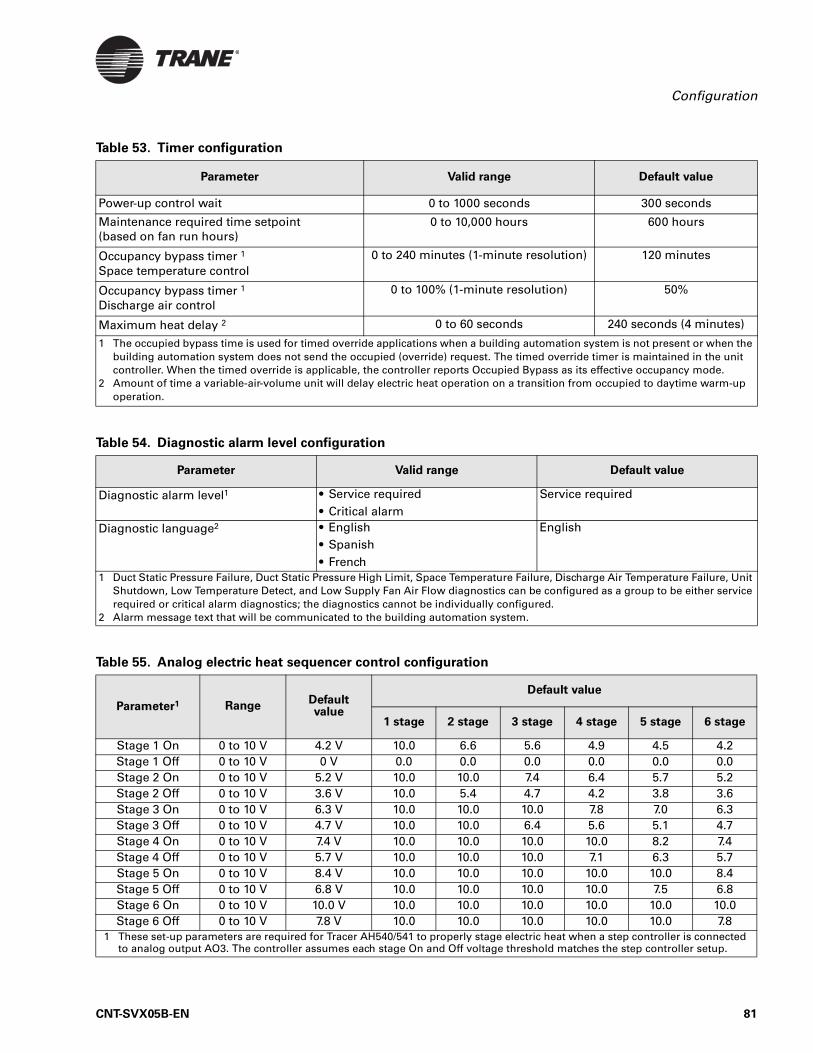
Configuration
Table 53. Timer configuration
Parameter Valid range Default value
Power-up control wait 0 to 1000 seconds 300 seconds
Maintenance required time setpoint (based on fan run hours)
0 to 10,000 hours 600 hours
Occupancy bypass timer 1
Space temperature control0 to 240 minutes (1-minute resolution) 120 minutes
Occupancy bypass timer 1
Discharge air control0 to 100% (1-minute resolution) 50%
Maximum heat delay 2 0 to 60 seconds 240 seconds (4 minutes)
1 The occupied bypass time is used for timed override applications when a building automation system is not present or when the building automation system does not send the occupied (override) request. The timed override timer is maintained in the unit controller. When the timed override is applicable, the controller reports Occupied Bypass as its effective occupancy mode.
2 Amount of time a variable-air-volume unit will delay electric heat operation on a transition from occupied to daytime warm-up operation.
Table 54. Diagnostic alarm level configuration
Parameter Valid range Default value
Diagnostic alarm level1 • Service required• Critical alarm
Service required
Diagnostic language2 • English• Spanish• French
English
1 Duct Static Pressure Failure, Duct Static Pressure High Limit, Space Temperature Failure, Discharge Air Temperature Failure, Unit Shutdown, Low Temperature Detect, and Low Supply Fan Air Flow diagnostics can be configured as a group to be either service required or critical alarm diagnostics; the diagnostics cannot be individually configured.
2 Alarm message text that will be communicated to the building automation system.
Table 55. Analog electric heat sequencer control configuration
Parameter1 Range Default value
Default value
1 stage 2 stage 3 stage 4 stage 5 stage 6 stage
Stage 1 On 0 to 10 V 4.2 V 10.0 6.6 5.6 4.9 4.5 4.2Stage 1 Off 0 to 10 V 0 V 0.0 0.0 0.0 0.0 0.0 0.0Stage 2 On 0 to 10 V 5.2 V 10.0 10.0 7.4 6.4 5.7 5.2Stage 2 Off 0 to 10 V 3.6 V 10.0 5.4 4.7 4.2 3.8 3.6Stage 3 On 0 to 10 V 6.3 V 10.0 10.0 10.0 7.8 7.0 6.3Stage 3 Off 0 to 10 V 4.7 V 10.0 10.0 6.4 5.6 5.1 4.7Stage 4 On 0 to 10 V 7.4 V 10.0 10.0 10.0 10.0 8.2 7.4Stage 4 Off 0 to 10 V 5.7 V 10.0 10.0 10.0 7.1 6.3 5.7Stage 5 On 0 to 10 V 8.4 V 10.0 10.0 10.0 10.0 10.0 8.4Stage 5 Off 0 to 10 V 6.8 V 10.0 10.0 10.0 10.0 7.5 6.8Stage 6 On 0 to 10 V 10.0 V 10.0 10.0 10.0 10.0 10.0 10.0Stage 6 Off 0 to 10 V 7.8 V 10.0 10.0 10.0 10.0 10.0 7.8
1 These set-up parameters are required for Tracer AH540/541 to properly stage electric heat when a step controller is connected to analog output AO3. The controller assumes each stage On and Off voltage threshold matches the step controller setup.
CNT-SVX05B-EN 81
Chapter 5 Configuration
82 CNT-SVX05B-EN
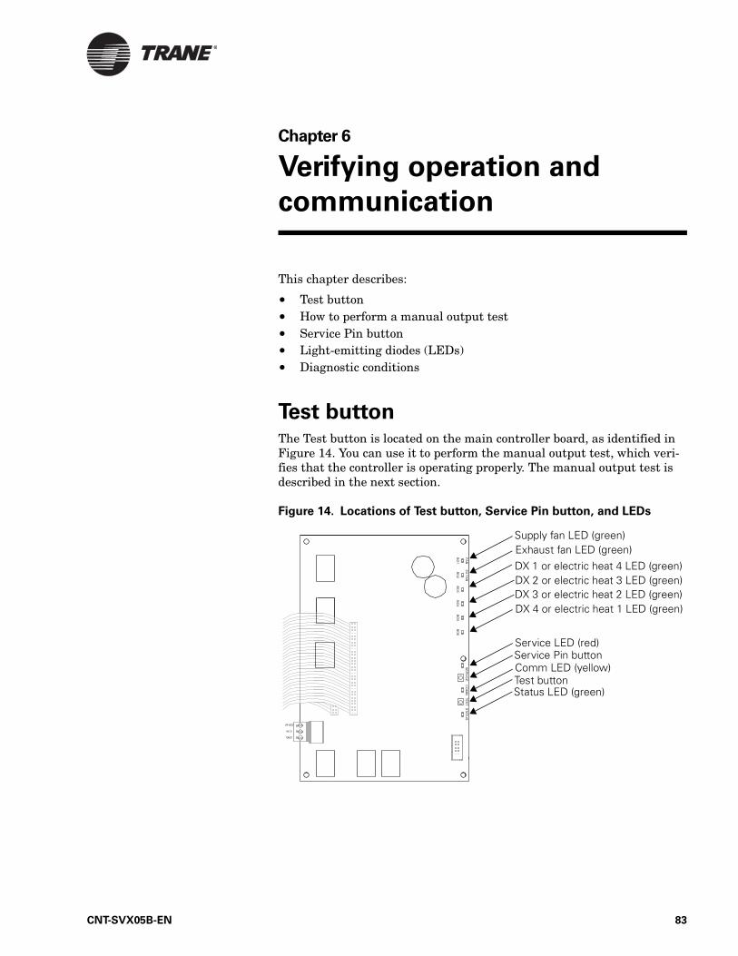
Chapter 6
Verifying operation and
communication
This chapter describes:
• Test button• How to perform a manual output test• Service Pin button• Light-emitting diodes (LEDs)• Diagnostic conditions
Test buttonThe Test button is located on the main controller board, as identified in Figure 14. You can use it to perform the manual output test, which veri-fies that the controller is operating properly. The manual output test is described in the next section.
Figure 14. Locations of Test button, Service Pin button, and LEDs
Supply fan LED (green)Exhaust fan LED (green)
Service Pin buttonComm LED (yellow)
Status LED (green)Test button
DX 1 or electric heat 4 LED (green)DX 2 or electric heat 3 LED (green)
DX 4 or electric heat 1 LED (green)
Service LED (red)
DX 3 or electric heat 2 LED (green)
CNT-SVX05B-EN 83
Chapter 6 Verifying operation and communication
Performing a manual output testThe manual output test sequentially controls all outputs to verify their wiring and operation. Normal operation of the controller is suspended while the manual output test is being performed.
You can use the manual output test to clear the controller of diagnostics. If any diagnostics are present when a manual test is initiated, the Status LED blinks twice. During the second step of the test, the controller attempts to clear the diagnostics. If the controller cannot clear a diagnos-tic, the controller exits the manual output test.
You can also use the manual output test for air and water balancing. Step four of the test provides cooling capacity. Step five provides heating capac-ity. Step four also opens the outdoor air damper to the minimum occupied position and controls the duct static-pressure to the duct static-pressure setpoint.
You can perform the manual output test in three ways:
• Press the Test button to proceed through the test sequence• Use the Rover service tool• Use the operator display
To perform a manual output test using the Test button:
1. Press and hold the Test button for 3 to 4 seconds, then release the button to start the test mode. The green Status LED light turns Off when the Test button is pressed, and then it blinks (as described in Table 59 on page 87) when the button is released to indicate the con-troller is in manual test mode.
2. Press the Test button (no more than once per second) to advance through the test sequence. Table 56 on page 85 shows the resulting activities of the outputs.
3. Finish the test by advancing through the complete test sequence. The test will end automatically if the unit remains in a single step for ten hours.
84 CNT-SVX05B-EN
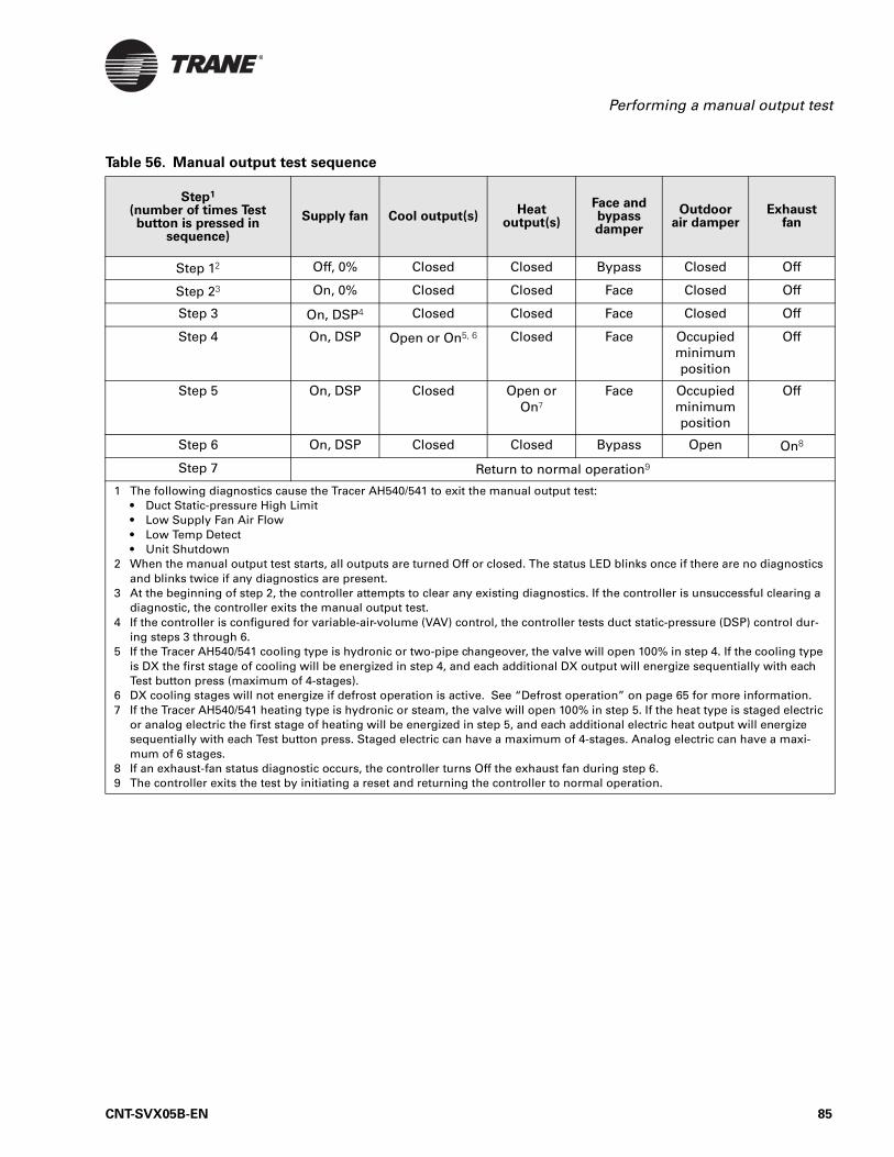
Performing a manual output test
Table 56. Manual output test sequence
Step1
(number of times Test button is pressed in
sequence)
Supply fan Cool output(s)Heat
output(s)
Face and bypass damper
Outdoor air damper
Exhaust fan
Step 12 Off, 0% Closed Closed Bypass Closed Off
Step 23 On, 0% Closed Closed Face Closed Off
Step 3 On, DSP4 Closed Closed Face Closed Off
Step 4 On, DSP Open or On5, 6 Closed Face Occupied minimum position
Off
Step 5 On, DSP Closed Open or On7
Face Occupied minimum position
Off
Step 6 On, DSP Closed Closed Bypass Open On8
Step 7 Return to normal operation9
1 The following diagnostics cause the Tracer AH540/541 to exit the manual output test:• Duct Static-pressure High Limit• Low Supply Fan Air Flow• Low Temp Detect• Unit Shutdown
2 When the manual output test starts, all outputs are turned Off or closed. The status LED blinks once if there are no diagnostics and blinks twice if any diagnostics are present.
3 At the beginning of step 2, the controller attempts to clear any existing diagnostics. If the controller is unsuccessful clearing a diagnostic, the controller exits the manual output test.
4 If the controller is configured for variable-air-volume (VAV) control, the controller tests duct static-pressure (DSP) control dur-ing steps 3 through 6.
5 If the Tracer AH540/541 cooling type is hydronic or two-pipe changeover, the valve will open 100% in step 4. If the cooling type is DX the first stage of cooling will be energized in step 4, and each additional DX output will energize sequentially with each Test button press (maximum of 4-stages).
6 DX cooling stages will not energize if defrost operation is active. See “Defrost operation” on page 65 for more information.7 If the Tracer AH540/541 heating type is hydronic or steam, the valve will open 100% in step 5. If the heat type is staged electric
or analog electric the first stage of heating will be energized in step 5, and each additional electric heat output will energize sequentially with each Test button press. Staged electric can have a maximum of 4-stages. Analog electric can have a maxi-mum of 6 stages.
8 If an exhaust-fan status diagnostic occurs, the controller turns Off the exhaust fan during step 6.9 The controller exits the test by initiating a reset and returning the controller to normal operation.
CNT-SVX05B-EN 85
Chapter 6 Verifying operation and communication
Service Pin buttonThe Service Pin button is located on the main circuit board as shown in Figure 14 on page 83. You can use the Service Pin button to:
• Identify a device• Add a device to the active group in Rover• Verify communication with Rover
• Make the green Status LED “wink” to verify that the controller is communicating on the link
Refer to the Rover Operation and Programming guide, EMTX-SVX01E-EN, for information on how to use the Service Pin button.
Interpreting LEDsThe information in this section will help you interpret LED activity. The location of each LED is shown in Figure 14 on page 83.
Binary output LEDs (green)
The FAN (BO1) LED indicates the status of the first binary output, which controls the supply fan. The EX FAN (BO2) LED indicates the status of the second binary output, which controls the exhaust fan. Binary outputs BO3, BO4, BO5, BO6 indicate the status of stages of DX cooling and elec-tric heat. Table 57 describes the LED activity for these binary outputs.
Note:
As an alternative to pressing the Service Pin button, you can hold down the zone sensor ON button for 10 seconds to verify communication with Rover by sending a Service Pin message request (see “Service Pin message request” on page 29).
Note:
Each binary output LED reflects the status of the output relay on the circuit board. It may or may not reflect the status of the equipment the binary output is controlling. Field wiring determines whether or not the state of the binary output LED also applies to status of the end device. Table 57 describes the LED states.
Table 57. Binary output LEDs (green)
LED activity Explanation
LED is On continuously The relay output is energized.
LED is Off continuously The relay output is de-energized or there is no power to the board.
86 CNT-SVX05B-EN
Interpreting LEDs
Service LED (red)
The Service LED indicates whether the controller is operating normally. Table 58 describes Service LED activity.
Status LED (green)
The green Status LED indicates whether the controller is receiving power and if the controller is in manual test mode. Table 59 describes Status LED activity.
Table 58. Service LED (red)
LED activity Explanation
LED is Off continuously when power is applied to the controller
The controller is operating normally.
LED is On continuously when power is applied to the controller
The controller is not working properly, or someone is pressing the Service Pin button.
LED blinks once every second
The controller is not executing the application software because the network connections and addressing have been removed.1
1 Restore the controller to normal operation using the Rover service tool.
Table 59. Status LED (green)
LED activity Explanation
LED is On continuously Power is on (normal operation).
LED blinks once The controller is in manual output test mode. No diagnostics are present.
LED blinks twice The controller is in manual output test mode. One or more diagnostic is present.
LED blinks (¼ second On, ¼ second Off for 10 seconds)
The auto-wink option is activated, and the controller is communicating.1
LED blinks rapidly Flash download is being received.
LED is Off continuously Either the power is Off or the controller has malfunctioned.
1 By sending a request from the Rover service tool, you can request the controller’s green LED to blink (“wink”), a notification that the controller received the signal and is communicating.
CNT-SVX05B-EN 87
Chapter 6 Verifying operation and communication
Comm LED (yellow)
The yellow Comm LED indicates the communication status of the control-ler. Table 60 describes Comm LED activity.
Required inputs for unit operation The following locally wired sensor or communicated inputs are required for each control function listed in Table 61. If any one of the sensors does not exist, the controller operates the control function.
Table 60. Comm LED (yellow)
LED activity Explanation
LED is Off continuously The controller is not detecting any communica-tion (normal for stand-alone applications).
LED blinks The controller detects communication (normal for communicating applications, including data sharing).
LED is On continuously An abnormal condition that may occur during discovery. The LED may flash fast enough to look as if it is on continuously. If this LED activity occurs at any other time, the site may have excessive radio frequency interference (RFI).
Table 61. Required inputs
Control functionInput required to be present
(locally wired sensor or communicated value)
Controller operation if input is not present
Variable-air-volume control Duct static pressure Diagnostic shutdown
Discharge air temperature control Discharge air temperature Diagnostic shutdown
Space temperature control Space temperatureDischarge air temperature
Diagnostic shutdownDiagnostic shutdown
Economizer operation Outdoor air temperatureMixed-air temperature
Economizer disabled
Space dehumidification Space relative humidity Dehumidification disabled
Two-pipe changeover Entering water temperature Hydronic capacity assumed to be appropriate for cooling
88 CNT-SVX05B-EN
Diagnostics
DiagnosticsTable 63 on page 91 describes the diagnostics that can be generated by the Tracer AH540/541 controller. There are three types of diagnostics:
• Critical—The controller shuts down the unit to prevent possible damage. The controller cannot operate until the diagnostic condition is corrected.
• Service required—The controller disables certain sequences of opera-tion while attempting to maintain unit operation. For example, if the mixed-air temperature sensor fails or is not wired, the controller dis-ables economizer operation.
• Informational—The controller operates normally.
Resetting diagnostics
Diagnostics that cause the unit to shutdown or disable certain operations are either latching or non-latching. Latching diagnostics require manual resetting. Non-latching diagnostics automatically clear when the condi-tion that caused the diagnostic is solved.
Resetting is similar to cycling power to the unit. Resetting clears any latching diagnostics and allows the controller to restart the air-handling unit, if it is running normally. If the condition that caused the latching diagnostic is still present, however, the controller immediately shuts down the unit.
You can reset diagnostics in a variety of ways:
• Manual output test• Cycling power to the controller• Building automation system • Rover service tool• Any communicating device able to access the diagnostic reset input of
the controller• Zone sensor fan mode switch• Operator display
Manual output test
Use the Test button on the controller during installation to verify proper end-device operation or during troubleshooting. When you press the Test button, the controller exercises all outputs in a predefined sequence. The first and last outputs of the sequence reset the controller diagnostics. See “Performing a manual output test” on page 84.
Cycling power
When the 24 Vac power to the controller is turned Off and then On, the unit cycles through a power-up sequence (see “Power-up sequence” on page 40). By default, the controller attempts to reset all diagnostics dur-ing this sequence.
CNT-SVX05B-EN 89
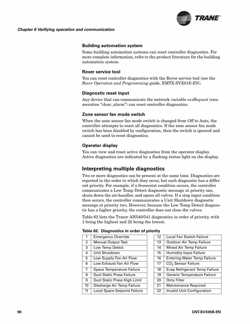
Chapter 6 Verifying operation and communication
Building automation system
Some building automation systems can reset controller diagnostics. For more complete information, refer to the product literature for the building automation system.
Rover service tool
You can reset controller diagnostics with the Rover service tool (see the Rover Operation and Programming guide, EMTX-SVX01E-EN).
Diagnostic reset input
Any device that can communicate the network variable nviRequest (enu-meration “clear_alarm”) can reset controller diagnostics.
Zone sensor fan mode switch
When the zone sensor fan mode switch is changed from Off to Auto, the controller attempts to reset all diagnostics. If the zone sensor fan mode switch has been disabled by configuration, then the switch is ignored and cannot be used to reset diagnostics.
Operator display
You can view and reset active diagnostics from the operator display. Active diagnostics are indicated by a flashing status light on the display.
Interpreting multiple diagnostics
Two or more diagnostics can be present at the same time. Diagnostics are reported in the order in which they occur, but each diagnostic has a differ-ent priority. For example, if a freezestat condition occurs, the controller communicates a Low Temp Detect diagnostic message at priority one, shuts down the air-handler, and opens all valves. If a stop input condition then occurs, the controller communicates a Unit Shutdown diagnostic message at priority two. However, because the Low Temp Detect diagnos-tic has a higher priority, the controller does not close the valves.
Table 62 lists the Tracer AH540/541 diagnostics in order of priority, with 1 being the highest and 22 being the lowest.
Table 62. Diagnostics in order of priority
1 Emergency Override 12 Local Fan Switch Failure2 Manual Output Test 13 Outdoor Air Temp Failure3 Low Temp Detect 14 Mixed Air Temp Failure4 Unit Shutdown 15 Humidity Input Failure5 Low Supply Fan Air Flow 16 Entering Water Temp Failure6 Low Exhaust Fan Air Flow 17 CO2 Sensor Failure
7 Space Temperature Failure 18 Evap Refrigerant Temp Failure8 Duct Static Press Failure 19 Generic Temperature Failure9 Duct Static Press High Limit 20 Dirty Filter10 Discharge Air Temp Failure 21 Maintenance Required11 Local Space Setpoint Failure 22 Invalid Unit Configuration
90 CNT-SVX05B-EN
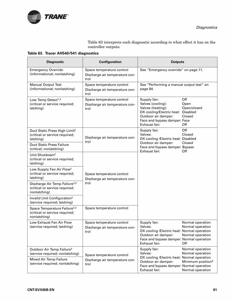
Diagnostics
Table 63 interprets each diagnostic according to what effect it has on the controller outputs.
Table 63. Tracer AH540/541 diagnostics
Diagnostic Configuration Outputs
Emergency Override(informational; nonlatching)
Space temperature controlDischarge air temperature con-trol
See “Emergency override” on page 71.
Manual Output Test(informational; nonlatching)
Space temperature controlDischarge air temperature con-trol
See “Performing a manual output test” on page 84.
Low Temp Detect1,2
(critical or service required; latching)
Space temperature controlDischarge air temperature con-trol
Supply fan: OffValves (cooling): OpenValves (heating): Open/closedDX cooling/Electric heat: DisabledOutdoor air damper: ClosedFace and bypass damper: FaceExhaust fan: Off
Duct Static Press High Limit2
(critical or service required; latching) Discharge air temperature con-
trol
Supply fan: OffValves: ClosedDX cooling /Electric heat: DisabledOutdoor air damper: ClosedFace and bypass damper: BypassExhaust fan: Off
Duct Static Press Failure(critical; nonlatching)
Unit Shutdown2
(critical or service required; latching)
Space temperature controlDischarge air temperature con-trol
Low Supply Fan Air Flow2
(critical or service required; latching)
Discharge Air Temp Failure2,3
(critical or service required; nonlatching)
Invalid Unit Configuration2
(service required; latching)
Space Temperature Failure2,3
(critical or service required; nonlatching)
Space temperature control
Low Exhaust Fan Air Flow(service required; latching)
Space temperature controlDischarge air temperature con-trol
Supply fan: Normal operationValves: Normal operationDX cooling /Electric heat: Normal operationOutdoor air damper: Normal operationFace and bypass damper: Normal operationExhaust fan: Off
Outdoor Air Temp Failure3
(service required; nonlatching) Space temperature controlDischarge air temperature con-trol
Supply fan: Normal operationValves: Normal operationDX cooling /Electric heat: Normal operationOutdoor air damper: Minimum position5 Face and bypass damper: Normal operationExhaust fan: Normal operation
Mixed Air Temp Failure(service required; nonlatching)
CNT-SVX05B-EN 91
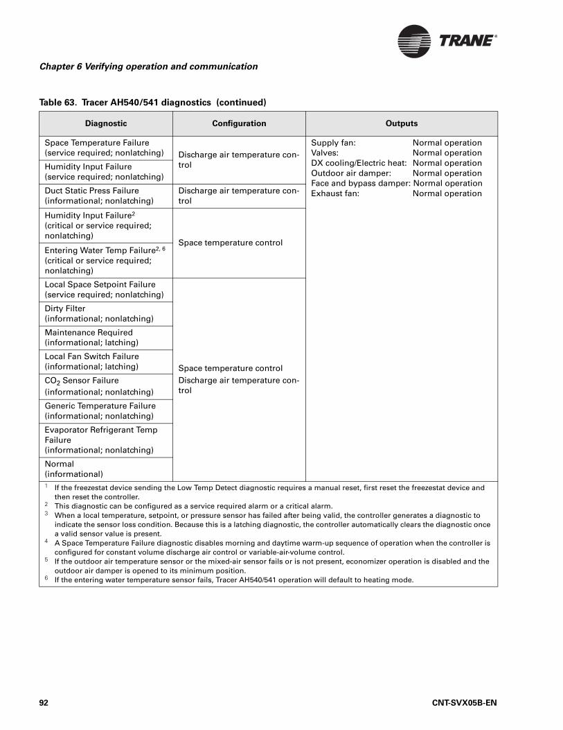
Chapter 6 Verifying operation and communication
Space Temperature Failure(service required; nonlatching) Discharge air temperature con-
trol
Supply fan: Normal operationValves: Normal operationDX cooling/Electric heat: Normal operationOutdoor air damper: Normal operationFace and bypass damper: Normal operationExhaust fan: Normal operation
Humidity Input Failure(service required; nonlatching)
Duct Static Press Failure(informational; nonlatching)
Discharge air temperature con-trol
Humidity Input Failure2
(critical or service required; nonlatching)
Space temperature controlEntering Water Temp Failure2, 6
(critical or service required; nonlatching)
Local Space Setpoint Failure(service required; nonlatching)
Space temperature controlDischarge air temperature con-trol
Dirty Filter(informational; nonlatching)
Maintenance Required(informational; latching)
Local Fan Switch Failure(informational; latching)
CO2 Sensor Failure(informational; nonlatching)
Generic Temperature Failure(informational; nonlatching)
Evaporator Refrigerant Temp Failure(informational; nonlatching)
Normal(informational)1 If the freezestat device sending the Low Temp Detect diagnostic requires a manual reset, first reset the freezestat device and
then reset the controller.2 This diagnostic can be configured as a service required alarm or a critical alarm.3 When a local temperature, setpoint, or pressure sensor has failed after being valid, the controller generates a diagnostic to
indicate the sensor loss condition. Because this is a latching diagnostic, the controller automatically clears the diagnostic once a valid sensor value is present.
4 A Space Temperature Failure diagnostic disables morning and daytime warm-up sequence of operation when the controller is configured for constant volume discharge air control or variable-air-volume control.
5 If the outdoor air temperature sensor or the mixed-air sensor fails or is not present, economizer operation is disabled and the outdoor air damper is opened to its minimum position.
6 If the entering water temperature sensor fails, Tracer AH540/541 operation will default to heating mode.
Table 63. Tracer AH540/541 diagnostics (continued)
Diagnostic Configuration Outputs
92 CNT-SVX05B-EN
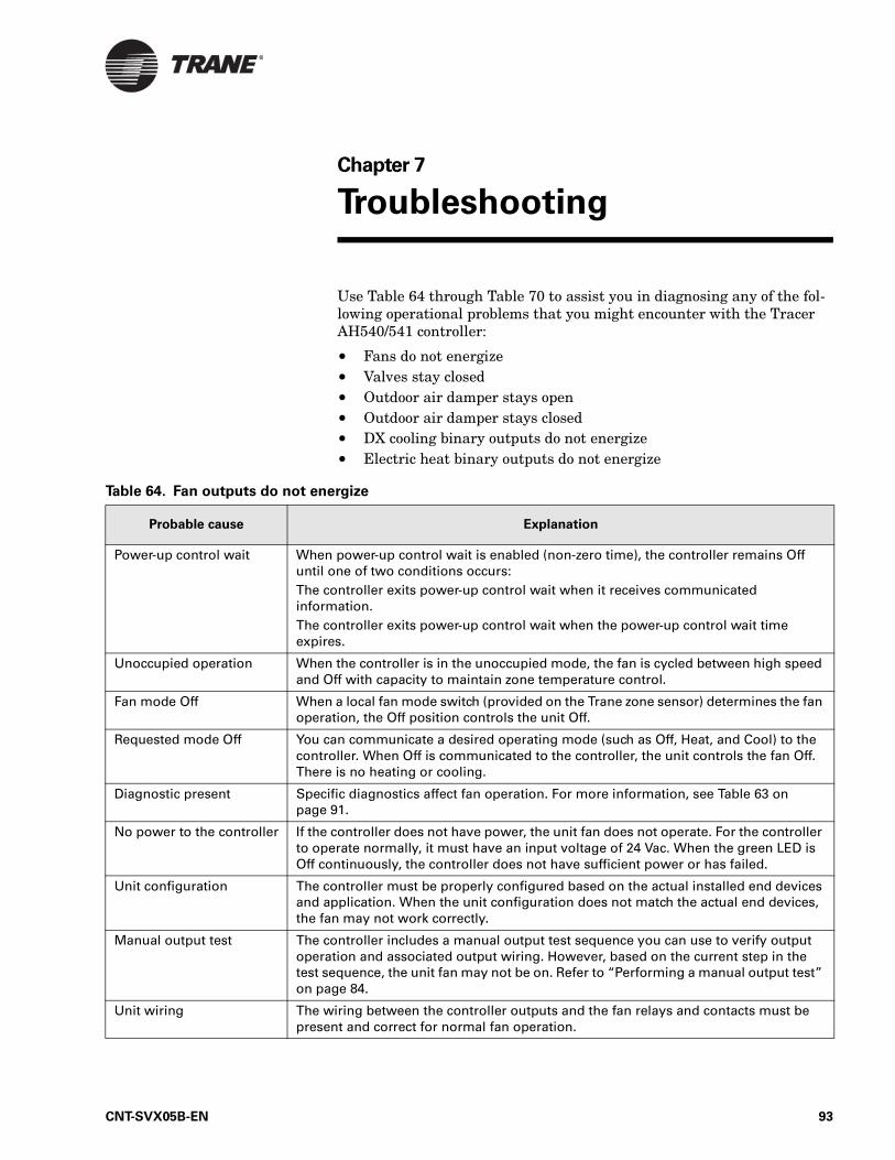
Chapter 7
Troubleshooting
Use Table 64 through Table 70 to assist you in diagnosing any of the fol-lowing operational problems that you might encounter with the Tracer AH540/541 controller:
• Fans do not energize• Valves stay closed• Outdoor air damper stays open• Outdoor air damper stays closed• DX cooling binary outputs do not energize• Electric heat binary outputs do not energize
Table 64. Fan outputs do not energize
Probable cause Explanation
Power-up control wait When power-up control wait is enabled (non-zero time), the controller remains Off until one of two conditions occurs:The controller exits power-up control wait when it receives communicated information.The controller exits power-up control wait when the power-up control wait time expires.
Unoccupied operation When the controller is in the unoccupied mode, the fan is cycled between high speed and Off with capacity to maintain zone temperature control.
Fan mode Off When a local fan mode switch (provided on the Trane zone sensor) determines the fan operation, the Off position controls the unit Off.
Requested mode Off You can communicate a desired operating mode (such as Off, Heat, and Cool) to the controller. When Off is communicated to the controller, the unit controls the fan Off. There is no heating or cooling.
Diagnostic present Specific diagnostics affect fan operation. For more information, see Table 63 on page 91.
No power to the controller If the controller does not have power, the unit fan does not operate. For the controller to operate normally, it must have an input voltage of 24 Vac. When the green LED is Off continuously, the controller does not have sufficient power or has failed.
Unit configuration The controller must be properly configured based on the actual installed end devices and application. When the unit configuration does not match the actual end devices, the fan may not work correctly.
Manual output test The controller includes a manual output test sequence you can use to verify output operation and associated output wiring. However, based on the current step in the test sequence, the unit fan may not be on. Refer to “Performing a manual output test” on page 84.
Unit wiring The wiring between the controller outputs and the fan relays and contacts must be present and correct for normal fan operation.
CNT-SVX05B-EN 93
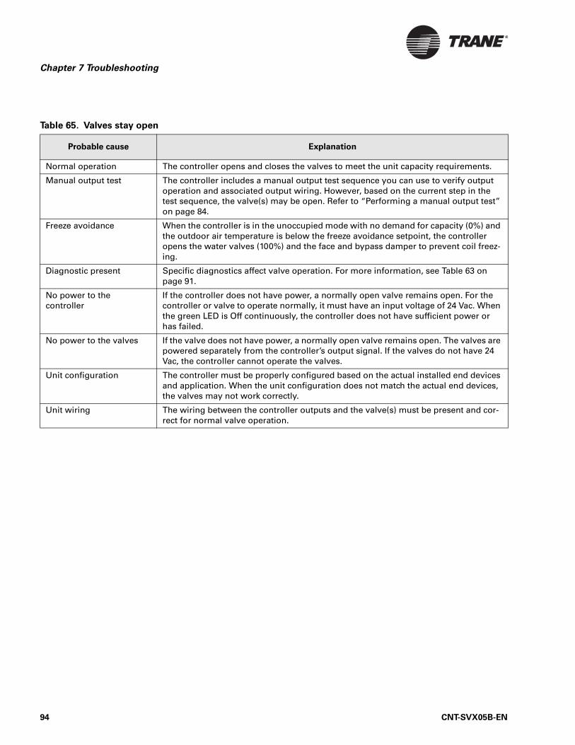
Chapter 7 Troubleshooting
Table 65. Valves stay open
Probable cause Explanation
Normal operation The controller opens and closes the valves to meet the unit capacity requirements.
Manual output test The controller includes a manual output test sequence you can use to verify output operation and associated output wiring. However, based on the current step in the test sequence, the valve(s) may be open. Refer to “Performing a manual output test” on page 84.
Freeze avoidance When the controller is in the unoccupied mode with no demand for capacity (0%) and the outdoor air temperature is below the freeze avoidance setpoint, the controller opens the water valves (100%) and the face and bypass damper to prevent coil freez-ing.
Diagnostic present Specific diagnostics affect valve operation. For more information, see Table 63 on page 91.
No power to the controller
If the controller does not have power, a normally open valve remains open. For the controller or valve to operate normally, it must have an input voltage of 24 Vac. When the green LED is Off continuously, the controller does not have sufficient power or has failed.
No power to the valves If the valve does not have power, a normally open valve remains open. The valves are powered separately from the controller’s output signal. If the valves do not have 24 Vac, the controller cannot operate the valves.
Unit configuration The controller must be properly configured based on the actual installed end devices and application. When the unit configuration does not match the actual end devices, the valves may not work correctly.
Unit wiring The wiring between the controller outputs and the valve(s) must be present and cor-rect for normal valve operation.
94 CNT-SVX05B-EN
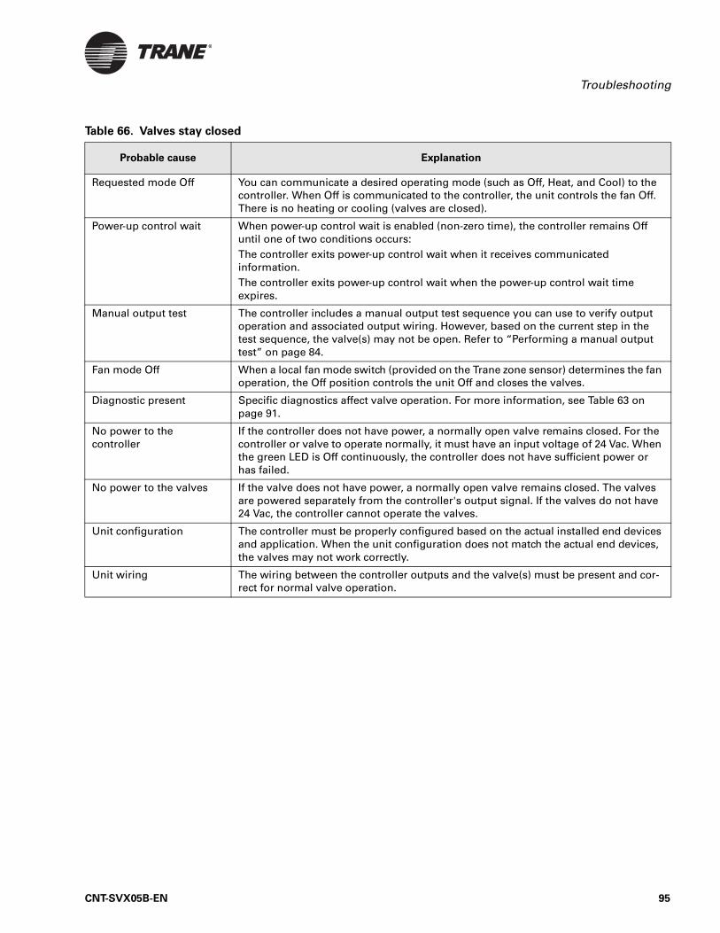
Troubleshooting
Table 66. Valves stay closed
Probable cause Explanation
Requested mode Off You can communicate a desired operating mode (such as Off, Heat, and Cool) to the controller. When Off is communicated to the controller, the unit controls the fan Off. There is no heating or cooling (valves are closed).
Power-up control wait When power-up control wait is enabled (non-zero time), the controller remains Off until one of two conditions occurs:The controller exits power-up control wait when it receives communicated information.The controller exits power-up control wait when the power-up control wait time expires.
Manual output test The controller includes a manual output test sequence you can use to verify output operation and associated output wiring. However, based on the current step in the test sequence, the valve(s) may not be open. Refer to “Performing a manual output test” on page 84.
Fan mode Off When a local fan mode switch (provided on the Trane zone sensor) determines the fan operation, the Off position controls the unit Off and closes the valves.
Diagnostic present Specific diagnostics affect valve operation. For more information, see Table 63 on page 91.
No power to the controller
If the controller does not have power, a normally open valve remains closed. For the controller or valve to operate normally, it must have an input voltage of 24 Vac. When the green LED is Off continuously, the controller does not have sufficient power or has failed.
No power to the valves If the valve does not have power, a normally open valve remains closed. The valves are powered separately from the controller's output signal. If the valves do not have 24 Vac, the controller cannot operate the valves.
Unit configuration The controller must be properly configured based on the actual installed end devices and application. When the unit configuration does not match the actual end devices, the valves may not work correctly.
Unit wiring The wiring between the controller outputs and the valve(s) must be present and cor-rect for normal valve operation.
CNT-SVX05B-EN 95
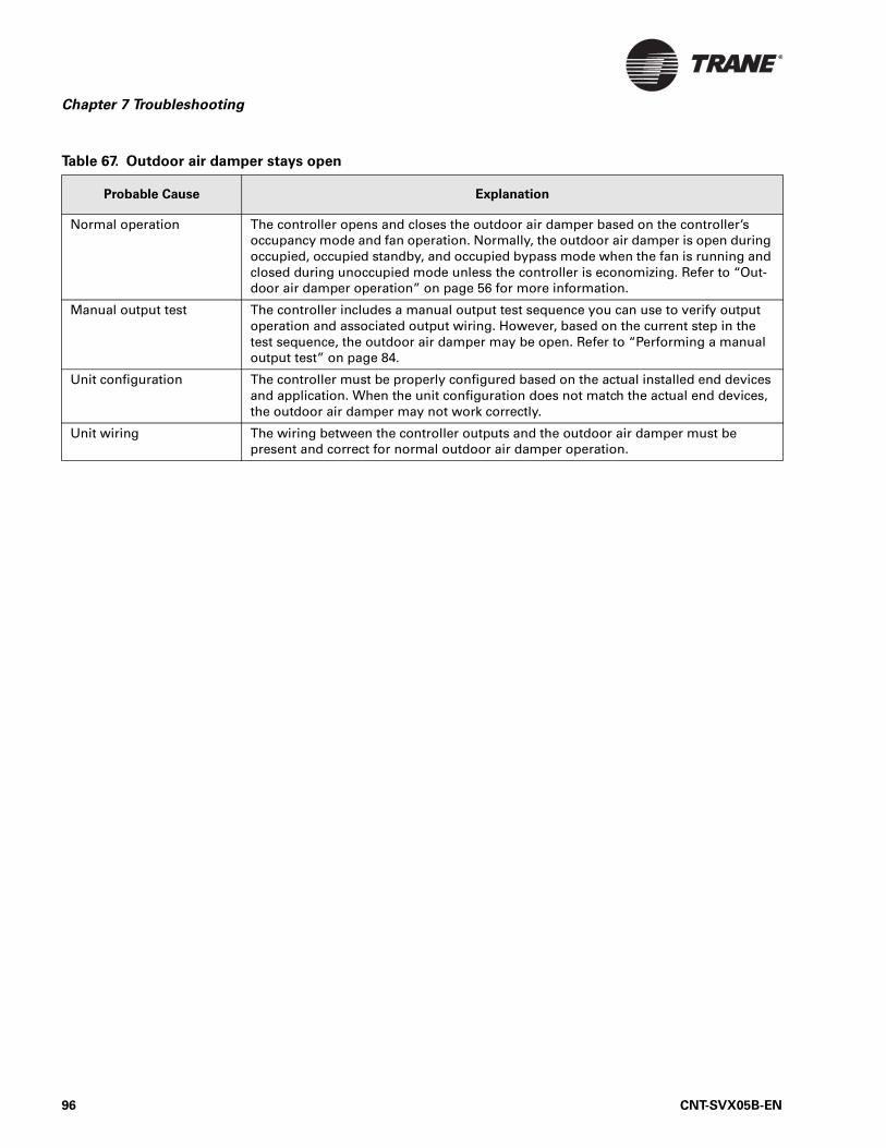
Chapter 7 Troubleshooting
Table 67. Outdoor air damper stays open
Probable Cause Explanation
Normal operation The controller opens and closes the outdoor air damper based on the controller’s occupancy mode and fan operation. Normally, the outdoor air damper is open during occupied, occupied standby, and occupied bypass mode when the fan is running and closed during unoccupied mode unless the controller is economizing. Refer to “Out-door air damper operation” on page 56 for more information.
Manual output test The controller includes a manual output test sequence you can use to verify output operation and associated output wiring. However, based on the current step in the test sequence, the outdoor air damper may be open. Refer to “Performing a manual output test” on page 84.
Unit configuration The controller must be properly configured based on the actual installed end devices and application. When the unit configuration does not match the actual end devices, the outdoor air damper may not work correctly.
Unit wiring The wiring between the controller outputs and the outdoor air damper must be present and correct for normal outdoor air damper operation.
96 CNT-SVX05B-EN
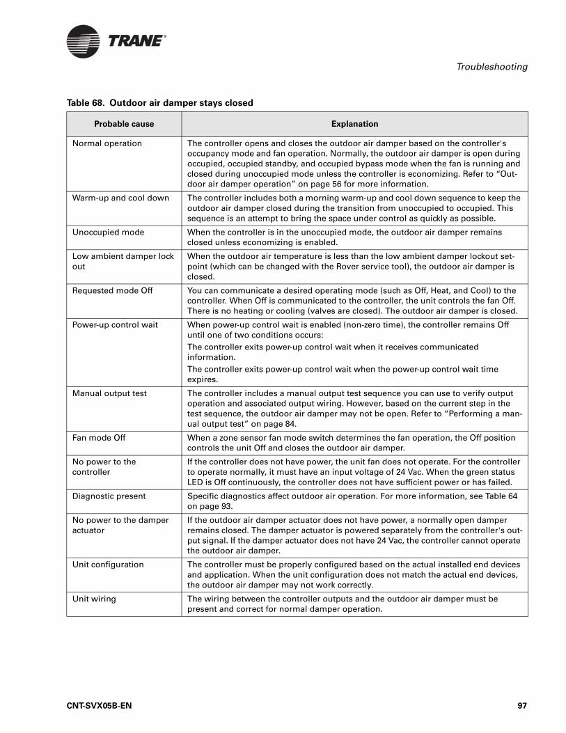
Troubleshooting
Table 68. Outdoor air damper stays closed
Probable cause Explanation
Normal operation The controller opens and closes the outdoor air damper based on the controller's occupancy mode and fan operation. Normally, the outdoor air damper is open during occupied, occupied standby, and occupied bypass mode when the fan is running and closed during unoccupied mode unless the controller is economizing. Refer to “Out-door air damper operation” on page 56 for more information.
Warm-up and cool down The controller includes both a morning warm-up and cool down sequence to keep the outdoor air damper closed during the transition from unoccupied to occupied. This sequence is an attempt to bring the space under control as quickly as possible.
Unoccupied mode When the controller is in the unoccupied mode, the outdoor air damper remains closed unless economizing is enabled.
Low ambient damper lock out
When the outdoor air temperature is less than the low ambient damper lockout set-point (which can be changed with the Rover service tool), the outdoor air damper is closed.
Requested mode Off You can communicate a desired operating mode (such as Off, Heat, and Cool) to the controller. When Off is communicated to the controller, the unit controls the fan Off. There is no heating or cooling (valves are closed). The outdoor air damper is closed.
Power-up control wait When power-up control wait is enabled (non-zero time), the controller remains Off until one of two conditions occurs:The controller exits power-up control wait when it receives communicated information.The controller exits power-up control wait when the power-up control wait time expires.
Manual output test The controller includes a manual output test sequence you can use to verify output operation and associated output wiring. However, based on the current step in the test sequence, the outdoor air damper may not be open. Refer to “Performing a man-ual output test” on page 84.
Fan mode Off When a zone sensor fan mode switch determines the fan operation, the Off position controls the unit Off and closes the outdoor air damper.
No power to thecontroller
If the controller does not have power, the unit fan does not operate. For the controller to operate normally, it must have an input voltage of 24 Vac. When the green status LED is Off continuously, the controller does not have sufficient power or has failed.
Diagnostic present Specific diagnostics affect outdoor air operation. For more information, see Table 64 on page 93.
No power to the damper actuator
If the outdoor air damper actuator does not have power, a normally open damper remains closed. The damper actuator is powered separately from the controller's out-put signal. If the damper actuator does not have 24 Vac, the controller cannot operate the outdoor air damper.
Unit configuration The controller must be properly configured based on the actual installed end devices and application. When the unit configuration does not match the actual end devices, the outdoor air damper may not work correctly.
Unit wiring The wiring between the controller outputs and the outdoor air damper must be present and correct for normal damper operation.
CNT-SVX05B-EN 97
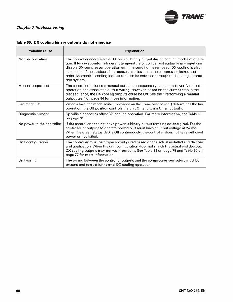
Chapter 7 Troubleshooting
Table 69. DX cooling binary outputs do not energize
Probable cause Explanation
Normal operation The controller energizes the DX cooling binary output during cooling modes of opera-tion. If low evaporator refrigerant temperature or coil defrost status binary input can disable DX compressor operation until the condition is removed. DX cooling is also suspended if the outdoor air temperature is less than the compressor lockout set-point. Mechanical cooling lockout can also be enforced through the building automa-tion system.
Manual output test The controller includes a manual output test sequence you can use to verify output operation and associated output wiring. However, based on the current step in the test sequence, the DX cooling outputs could be Off. See the “Performing a manual output test” on page 84 for more information.
Fan mode Off When a local fan mode switch (provided on the Trane zone sensor) determines the fan operation, the Off position controls the unit Off and turns Off all outputs.
Diagnostic present Specific diagnostics affect DX cooling operation. For more information, see Table 63 on page 91.
No power to the controller If the controller does not have power, a binary output remains de-energized. For the controller or outputs to operate normally, it must have an input voltage of 24 Vac. When the green Status LED is Off continuously, the controller does not have sufficient power or has failed.
Unit configuration The controller must be properly configured based on the actual installed end devices and application. When the unit configuration does not match the actual end devices, DX cooling outputs may not work correctly. See Table 34 on page 75 and Table 39 on page 77 for more information.
Unit wiring The wiring between the controller outputs and the compressor contactors must be present and correct for normal DX cooling operation.
98 CNT-SVX05B-EN
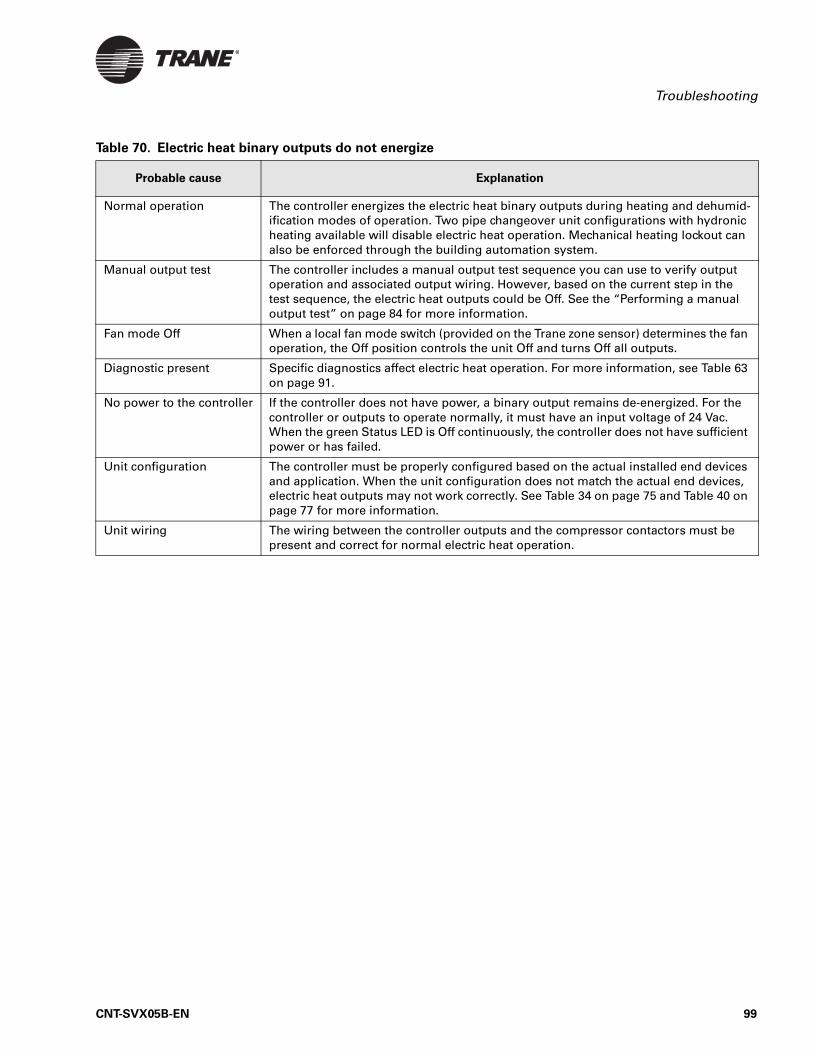
Troubleshooting
Table 70. Electric heat binary outputs do not energize
Probable cause Explanation
Normal operation The controller energizes the electric heat binary outputs during heating and dehumid-ification modes of operation. Two pipe changeover unit configurations with hydronic heating available will disable electric heat operation. Mechanical heating lockout can also be enforced through the building automation system.
Manual output test The controller includes a manual output test sequence you can use to verify output operation and associated output wiring. However, based on the current step in the test sequence, the electric heat outputs could be Off. See the “Performing a manual output test” on page 84 for more information.
Fan mode Off When a local fan mode switch (provided on the Trane zone sensor) determines the fan operation, the Off position controls the unit Off and turns Off all outputs.
Diagnostic present Specific diagnostics affect electric heat operation. For more information, see Table 63 on page 91.
No power to the controller If the controller does not have power, a binary output remains de-energized. For the controller or outputs to operate normally, it must have an input voltage of 24 Vac. When the green Status LED is Off continuously, the controller does not have sufficient power or has failed.
Unit configuration The controller must be properly configured based on the actual installed end devices and application. When the unit configuration does not match the actual end devices, electric heat outputs may not work correctly. See Table 34 on page 75 and Table 40 on page 77 for more information.
Unit wiring The wiring between the controller outputs and the compressor contactors must be present and correct for normal electric heat operation.
CNT-SVX05B-EN 99

Chapter 7 Troubleshooting
100 CNT-SVX05B-EN
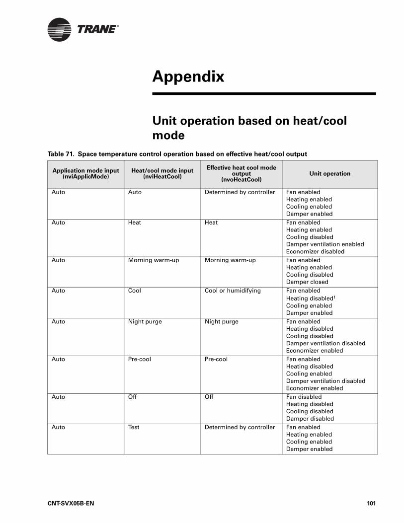
Appendix
Unit operation based on heat/cool
mode
Table 71. Space temperature control operation based on effective heat/cool output
Application mode input(nviApplicMode)
Heat/cool mode input(nviHeatCool)
Effective heat cool mode output
(nvoHeatCool)Unit operation
Auto Auto Determined by controller Fan enabledHeating enabledCooling enabledDamper enabled
Auto Heat Heat Fan enabledHeating enabledCooling disabledDamper ventilation enabledEconomizer disabled
Auto Morning warm-up Morning warm-up Fan enabledHeating enabled Cooling disabledDamper closed
Auto Cool Cool or humidifying Fan enabledHeating disabled1
Cooling enabledDamper enabled
Auto Night purge Night purge Fan enabledHeating disabledCooling disabledDamper ventilation disabledEconomizer enabled
Auto Pre-cool Pre-cool Fan enabledHeating disabledCooling enabledDamper ventilation disabled Economizer enabled
Auto Off Off Fan disabledHeating disabledCooling disabledDamper disabled
Auto Test Determined by controller Fan enabledHeating enabledCooling enabledDamper enabled
CNT-SVX05B-EN 101
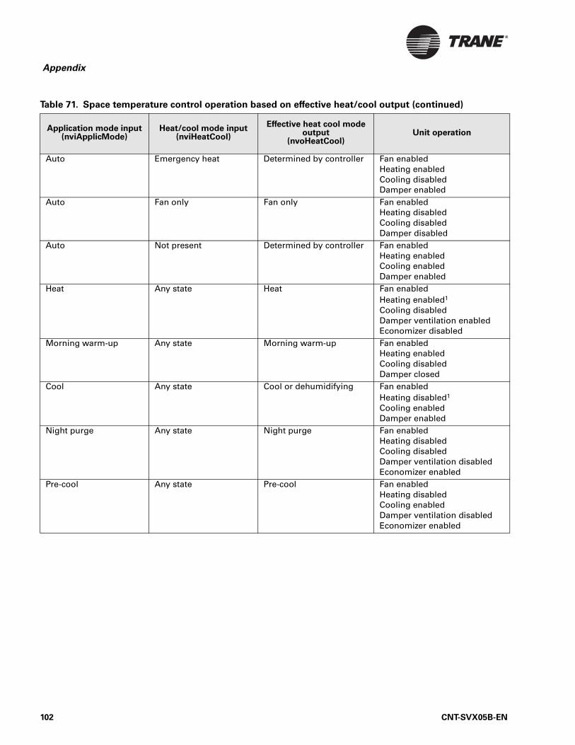
Appendix
Auto Emergency heat Determined by controller Fan enabledHeating enabledCooling disabledDamper enabled
Auto Fan only Fan only Fan enabledHeating disabledCooling disabledDamper disabled
Auto Not present Determined by controller Fan enabledHeating enabledCooling enabledDamper enabled
Heat Any state Heat Fan enabledHeating enabled1
Cooling disabledDamper ventilation enabledEconomizer disabled
Morning warm-up Any state Morning warm-up Fan enabledHeating enabledCooling disabledDamper closed
Cool Any state Cool or dehumidifying Fan enabledHeating disabled1
Cooling enabledDamper enabled
Night purge Any state Night purge Fan enabledHeating disabledCooling disabledDamper ventilation disabledEconomizer enabled
Pre-cool Any state Pre-cool Fan enabledHeating disabledCooling enabledDamper ventilation disabledEconomizer enabled
Table 71. Space temperature control operation based on effective heat/cool output (continued)
Application mode input(nviApplicMode)
Heat/cool mode input(nviHeatCool)
Effective heat cool mode output
(nvoHeatCool)Unit operation
102 CNT-SVX05B-EN
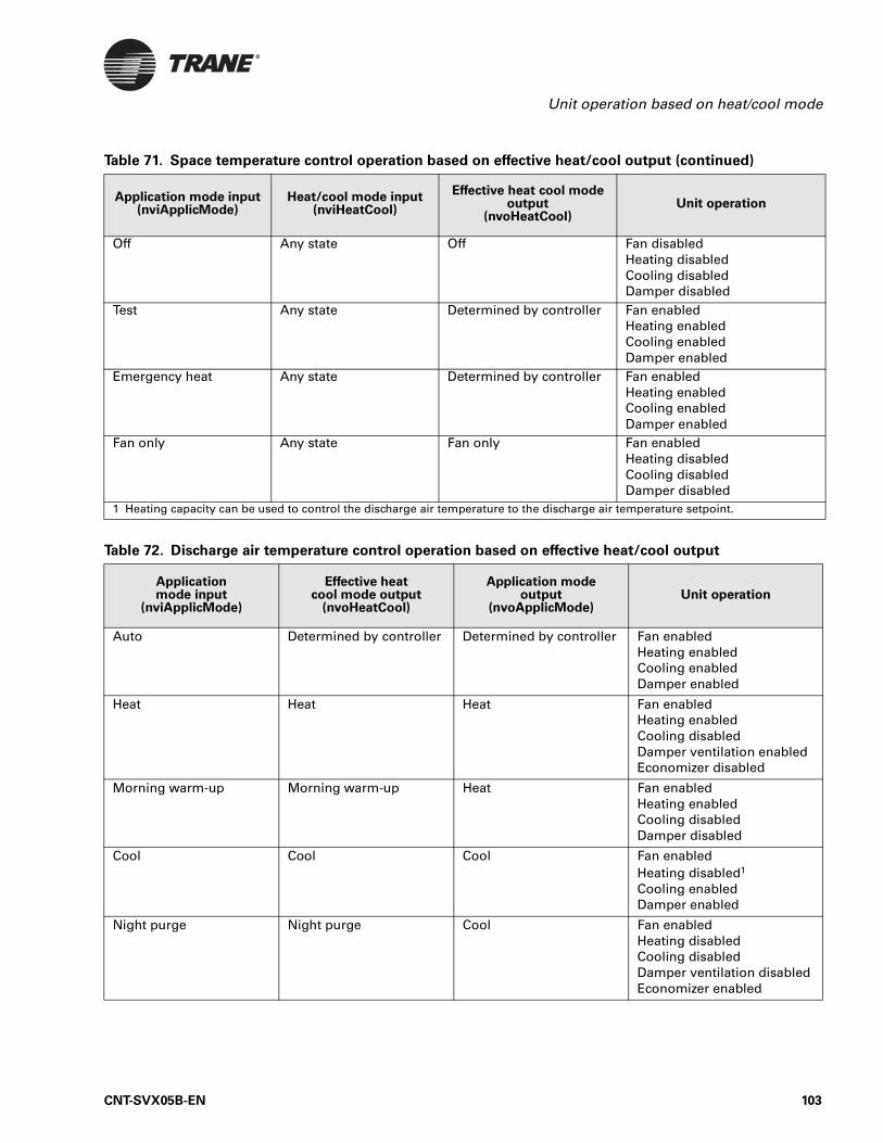
Unit operation based on heat/cool mode
Off Any state Off Fan disabledHeating disabledCooling disabledDamper disabled
Test Any state Determined by controller Fan enabledHeating enabledCooling enabledDamper enabled
Emergency heat Any state Determined by controller Fan enabledHeating enabledCooling enabledDamper enabled
Fan only Any state Fan only Fan enabledHeating disabledCooling disabledDamper disabled
1 Heating capacity can be used to control the discharge air temperature to the discharge air temperature setpoint.
Table 71. Space temperature control operation based on effective heat/cool output (continued)
Application mode input(nviApplicMode)
Heat/cool mode input(nviHeatCool)
Effective heat cool mode output
(nvoHeatCool)Unit operation
Table 72. Discharge air temperature control operation based on effective heat/cool output
Application mode input
(nviApplicMode)
Effective heat cool mode output
(nvoHeatCool)
Application mode output
(nvoApplicMode)Unit operation
Auto Determined by controller Determined by controller Fan enabledHeating enabledCooling enabledDamper enabled
Heat Heat Heat Fan enabledHeating enabledCooling disabledDamper ventilation enabledEconomizer disabled
Morning warm-up Morning warm-up Heat Fan enabledHeating enabledCooling disabledDamper disabled
Cool Cool Cool Fan enabledHeating disabled1
Cooling enabledDamper enabled
Night purge Night purge Cool Fan enabledHeating disabledCooling disabledDamper ventilation disabledEconomizer enabled
CNT-SVX05B-EN 103
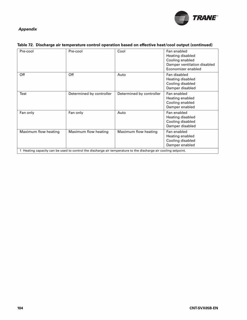
Appendix
Pre-cool Pre-cool Cool Fan enabledHeating disabledCooling enabledDamper ventilation disabledEconomizer enabled
Off Off Auto Fan disabledHeating disabledCooling disabledDamper disabled
Test Determined by controller Determined by controller Fan enabledHeating enabledCooling enabledDamper enabled
Fan only Fan only Auto Fan enabledHeating disabledCooling disabledDamper disabled
Maximum flow heating Maximum flow heating Maximum flow heating Fan enabledHeating enabledCooling disabledDamper enabled
1 Heating capacity can be used to control the discharge air temperature to the discharge air cooling setpoint.
Table 72. Discharge air temperature control operation based on effective heat/cool output (continued)
104 CNT-SVX05B-EN
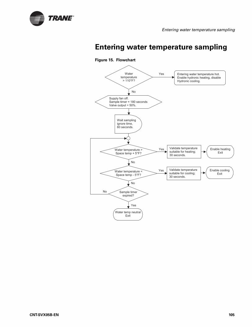
Entering water temperature sampling
Entering water temperature sampling
Figure 15. Flowchart
CNT-SVX05B-EN 105
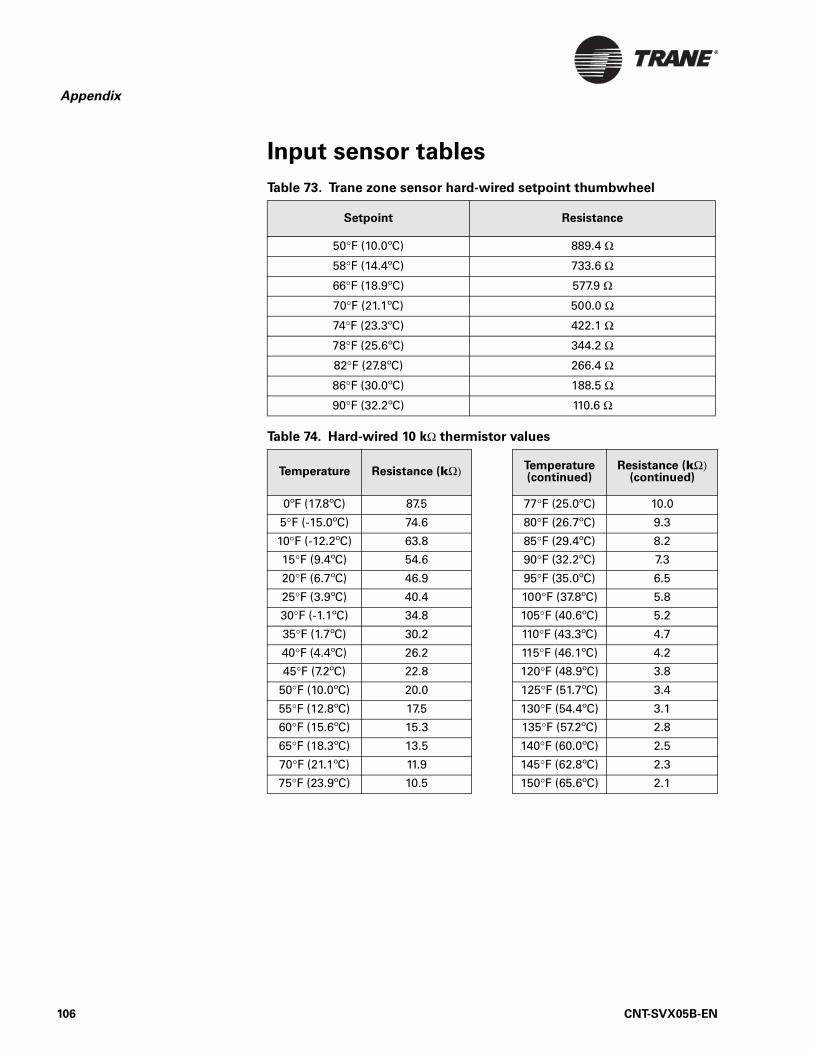
Appendix
Input sensor tables
Table 73. Trane zone sensor hard-wired setpoint thumbwheel
Setpoint Resistance
50°F (10.0ºC) 889.4 Ω
58°F (14.4ºC) 733.6 Ω
66°F (18.9ºC) 577.9 Ω
70°F (21.1ºC) 500.0 Ω
74°F (23.3ºC) 422.1 Ω
78°F (25.6ºC) 344.2 Ω
82°F (27.8ºC) 266.4 Ω
86°F (30.0ºC) 188.5 Ω
90°F (32.2ºC) 110.6 Ω
Table 74. Hard-wired 10 kΩ thermistor values
Temperature Resistance (kΩ) Temperature(continued)
Resistance (kΩ)(continued)
0ºF (17.8ºC) 87.5 77°F (25.0ºC) 10.0
5°F (-15.0ºC) 74.6 80°F (26.7ºC) 9.3
10°F (-12.2ºC) 63.8 85°F (29.4ºC) 8.2
15°F (9.4ºC) 54.6 90°F (32.2ºC) 7.3
20°F (6.7ºC) 46.9 95°F (35.0ºC) 6.5
25°F (3.9ºC) 40.4 100°F (37.8ºC) 5.8
30°F (-1.1ºC) 34.8 105°F (40.6ºC) 5.2
35°F (1.7ºC) 30.2 110°F (43.3ºC) 4.7
40°F (4.4ºC) 26.2 115°F (46.1ºC) 4.2
45°F (7.2ºC) 22.8 120°F (48.9ºC) 3.8
50°F (10.0ºC) 20.0 125°F (51.7ºC) 3.4
55°F (12.8ºC) 17.5 130°F (54.4ºC) 3.1
60°F (15.6ºC) 15.3 135°F (57.2ºC) 2.8
65°F (18.3ºC) 13.5 140°F (60.0ºC) 2.5
70°F (21.1ºC) 11.9 145°F (62.8ºC) 2.3
75°F (23.9ºC) 10.5 150°F (65.6ºC) 2.1
106 CNT-SVX05B-EN
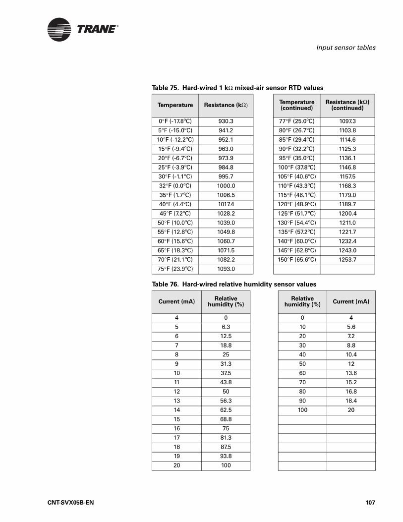
Input sensor tables
Table 75. Hard-wired 1 kΩ mixed-air sensor RTD values
Temperature Resistance (kΩ) Temperature(continued)
Resistance (kΩ)(continued)
0°F (-17.8ºC) 930.3 77°F (25.0ºC) 1097.3
5°F (-15.0ºC) 941.2 80°F (26.7ºC) 1103.8
10°F (-12.2ºC) 952.1 85°F (29.4ºC) 1114.6
15°F (-9.4ºC) 963.0 90°F (32.2ºC) 1125.3
20°F (-6.7ºC) 973.9 95°F (35.0ºC) 1136.1
25°F (-3.9ºC) 984.8 100°F (37.8ºC) 1146.8
30°F (-1.1ºC) 995.7 105°F (40.6ºC) 1157.5
32°F (0.0ºC) 1000.0 110°F (43.3ºC) 1168.3
35°F (1.7ºC) 1006.5 115°F (46.1ºC) 1179.0
40°F (4.4ºC) 1017.4 120°F (48.9ºC) 1189.7
45°F (7.2ºC) 1028.2 125°F (51.7ºC) 1200.4
50°F (10.0ºC) 1039.0 130°F (54.4ºC) 1211.0
55°F (12.8ºC) 1049.8 135°F (57.2ºC) 1221.7
60°F (15.6ºC) 1060.7 140°F (60.0ºC) 1232.4
65°F (18.3ºC) 1071.5 145°F (62.8ºC) 1243.0
70°F (21.1ºC) 1082.2 150°F (65.6ºC) 1253.7
75°F (23.9ºC) 1093.0
Table 76. Hard-wired relative humidity sensor values
Current (mA)Relative
humidity (%)Relative
humidity (%)Current (mA)
4 0 0 4
5 6.3 10 5.6
6 12.5 20 7.2
7 18.8 30 8.8
8 25 40 10.4
9 31.3 50 12
10 37.5 60 13.6
11 43.8 70 15.2
12 50 80 16.8
13 56.3 90 18.4
14 62.5 100 20
15 68.8
16 75
17 81.3
18 87.5
19 93.8
20 100
CNT-SVX05B-EN 107
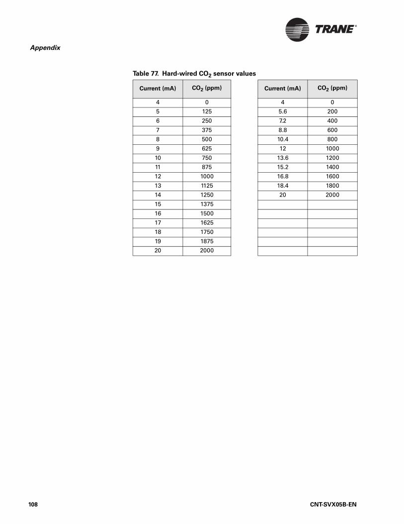
Appendix
Table 77. Hard-wired CO2 sensor values
Current (mA) CO2 (ppm) Current (mA) CO2 (ppm)
4 0 4 0
5 125 5.6 200
6 250 7.2 400
7 375 8.8 600
8 500 10.4 800
9 625 12 1000
10 750 13.6 1200
11 875 15.2 1400
12 1000 16.8 1600
13 1125 18.4 1800
14 1250 20 2000
15 1375
16 1500
17 1625
18 1750
19 1875
20 2000
108 CNT-SVX05B-EN
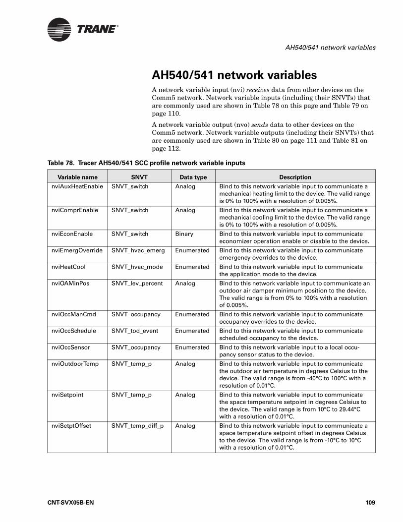
AH540/541 network variables
AH540/541 network variablesA network variable input (nvi) receives data from other devices on the Comm5 network. Network variable inputs (including their SNVTs) that are commonly used are shown in Table 78 on this page and Table 79 on page 110.
A network variable output (nvo) sends data to other devices on the Comm5 network. Network variable outputs (including their SNVTs) that are commonly used are shown in Table 80 on page 111 and Table 81 on page 112.
Table 78. Tracer AH540/541 SCC profile network variable inputs
Variable name SNVT Data type Description
nviAuxHeatEnable SNVT_switch Analog Bind to this network variable input to communicate a mechanical heating limit to the device. The valid range is 0% to 100% with a resolution of 0.005%.
nviComprEnable SNVT_switch Analog Bind to this network variable input to communicate a mechanical cooling limit to the device. The valid range is 0% to 100% with a resolution of 0.005%.
nviEconEnable SNVT_switch Binary Bind to this network variable input to communicate economizer operation enable or disable to the device.
nviEmergOverride SNVT_hvac_emerg Enumerated Bind to this network variable input to communicate emergency overrides to the device.
nviHeatCool SNVT_hvac_mode Enumerated Bind to this network variable input to communicate the application mode to the device.
nviOAMinPos SNVT_lev_percent Analog Bind to this network variable input to communicate an outdoor air damper minimum position to the device. The valid range is from 0% to 100% with a resolution of 0.005%.
nviOccManCmd SNVT_occupancy Enumerated Bind to this network variable input to communicate occupancy overrides to the device.
nviOccSchedule SNVT_tod_event Enumerated Bind to this network variable input to communicate scheduled occupancy to the device.
nviOccSensor SNVT_occupancy Enumerated Bind to this network variable input to a local occu-pancy sensor status to the device.
nviOutdoorTemp SNVT_temp_p Analog Bind to this network variable input to communicate the outdoor air temperature in degrees Celsius to the device. The valid range is from -40°C to 100°C with a resolution of 0.01°C.
nviSetpoint SNVT_temp_p Analog Bind to this network variable input to communicate the space temperature setpoint in degrees Celsius to the device. The valid range is from 10°C to 29.44°C with a resolution of 0.01°C.
nviSetptOffset SNVT_temp_diff_p Analog Bind to this network variable input to communicate a space temperature setpoint offset in degrees Celsius to the device. The valid range is from -10°C to 10°C with a resolution of 0.01°C.
CNT-SVX05B-EN 109
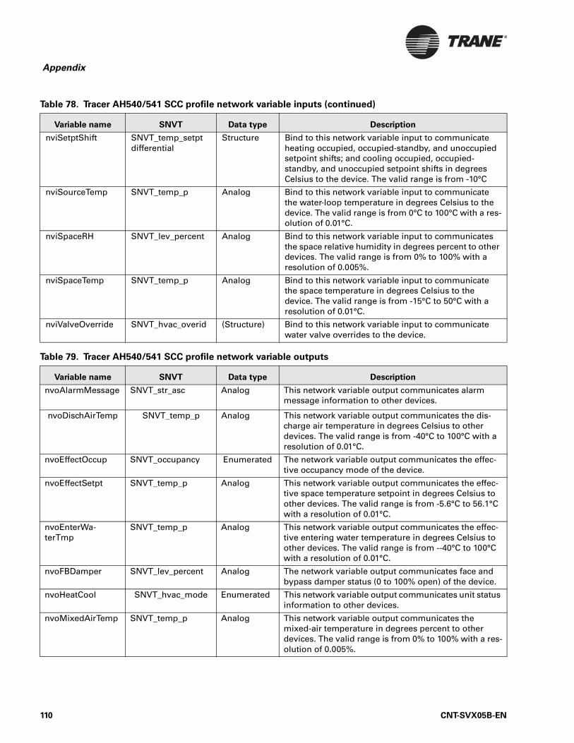
Appendix
nviSetptShift SNVT_temp_setpt differential
Structure Bind to this network variable input to communicate heating occupied, occupied-standby, and unoccupied setpoint shifts; and cooling occupied, occupied-standby, and unoccupied setpoint shifts in degrees Celsius to the device. The valid range is from -10°C
nviSourceTemp SNVT_temp_p Analog Bind to this network variable input to communicate the water-loop temperature in degrees Celsius to the device. The valid range is from 0°C to 100°C with a res-olution of 0.01°C.
nviSpaceRH SNVT_lev_percent Analog Bind to this network variable input to communicates the space relative humidity in degrees percent to other devices. The valid range is from 0% to 100% with a resolution of 0.005%.
nviSpaceTemp SNVT_temp_p Analog Bind to this network variable input to communicate the space temperature in degrees Celsius to the device. The valid range is from -15°C to 50°C with a resolution of 0.01°C.
nviValveOverride SNVT_hvac_overid (Structure) Bind to this network variable input to communicate water valve overrides to the device.
Table 79. Tracer AH540/541 SCC profile network variable outputs
Variable name SNVT Data type Description
nvoAlarmMessage SNVT_str_asc Analog This network variable output communicates alarm message information to other devices.
nvoDischAirTemp SNVT_temp_p Analog This network variable output communicates the dis-charge air temperature in degrees Celsius to other devices. The valid range is from -40°C to 100°C with a resolution of 0.01°C.
nvoEffectOccup SNVT_occupancy Enumerated The network variable output communicates the effec-tive occupancy mode of the device.
nvoEffectSetpt SNVT_temp_p Analog This network variable output communicates the effec-tive space temperature setpoint in degrees Celsius to other devices. The valid range is from -5.6°C to 56.1°C with a resolution of 0.01°C.
nvoEnterWa-terTmp
SNVT_temp_p Analog This network variable output communicates the effec-tive entering water temperature in degrees Celsius to other devices. The valid range is from --40°C to 100°C with a resolution of 0.01°C.
nvoFBDamper SNVT_lev_percent Analog The network variable output communicates face and bypass damper status (0 to 100% open) of the device.
nvoHeatCool SNVT_hvac_mode Enumerated This network variable output communicates unit status information to other devices.
nvoMixedAirTemp SNVT_temp_p Analog This network variable output communicates the mixed-air temperature in degrees percent to other devices. The valid range is from 0% to 100% with a res-olution of 0.005%.
Table 78. Tracer AH540/541 SCC profile network variable inputs (continued)
Variable name SNVT Data type Description
110 CNT-SVX05B-EN
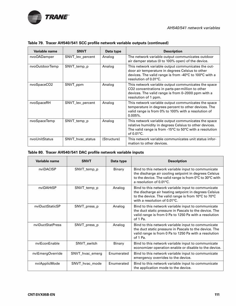
AH540/541 network variables
nvoOADamper SNVT_lev_percent Analog The network variable output communicates outdoor air damper status (0 to 100% open) of the device.
nvoOutdoorTemp SNVT_temp_p Analog This network variable output communicates the out-door air temperature in degrees Celsius to other devices. The valid range is from -40°C to 100°C with a resolution of 0.01°C.
nvoSpaceCO2 SNVT_ppm Analog This network variable output communicates the space CO2 concentrations in parts-per-million to other devices. The valid range is from 0–2000 ppm with a resolution of 1 ppm.
nvoSpaceRH SNVT_lev_percent Analog This network variable output communicates the space temperature in degrees percent to other devices. The valid range is from 0% to 100% with a resolution of 0.005%.
nvoSpaceTemp SNVT_temp_p Analog This network variable output communicates the space relative humidity in degrees Celsius to other devices. The valid range is from -15°C to 50°C with a resolution of 0.01°C.
nvoUnitStatus SNVT_hvac_status (Structure) This network variable communicates unit status infor-mation to other devices.
Table 80. Tracer AH540/541 DAC profile network variable inputs
Variable name SNVT Data type Description
nviDACISP SNVT_temp_p Binary Bind to this network variable input to communicate the discharge air cooling setpoint in degrees Celsius to the device. The valid range is from 0°C to 30°C with a resolution of 0.01°C.
nviDAHtSP SNVT_temp_p Analog Bind to this network variable input to communicate the discharge air heating setpoint in degrees Celsius to the device. The valid range is from 10°C to 70°C with a resolution of 0.01°C.
nviDuctStaticSP SNVT_press_p Analog Bind to this network variable input to communicate the duct static pressure in Pascals to the device. The valid range is from 0 Pa to 1250 Pa with a resolution of 1 Pa.
nviDuctStatPress SNVT_press_p Analog Bind to this network variable input to communicate the duct static pressure in Pascals to the device. The valid range is from 0 Pa to 1250 Pa with a resolution of 1 Pa.
nviEconEnable SNVT_switch Binary Bind to this network variable input to communicate economizer operation enable or disable to the device.
nviEmergOverride SNVT_hvac_emerg Enumerated Bind to this network variable input to communicate emergency overrides to the device.
nviApplicMode SNVT_hvac_mode Enumerated Bind to this network variable input to communicate the application mode to the device.
Table 79. Tracer AH540/541 SCC profile network variable outputs (continued)
Variable name SNVT Data type Description
CNT-SVX05B-EN 111
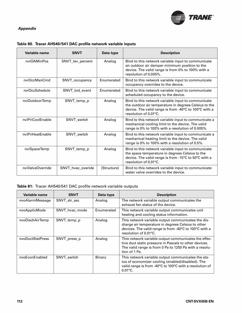
Appendix
nviOAMinPos SNVT_lev_percent Analog Bind to this network variable input to communicate an outdoor air damper minimum position to the device. The valid range is from 0% to 100% with a resolution of 0.005%.
nviOccManCmd SNVT_occupancy Enumerated Bind to this network variable input to communicate occupancy overrides to the device.
nviOccSchedule SNVT_tod_event Enumerated Bind to this network variable input to communicate scheduled occupancy to the device.
nviOutdoorTemp SNVT_temp_p Analog Bind to this network variable input to communicate the outdoor air temperature in degrees Celsius to the device. The valid range is from -40°C to 100°C with a resolution of 0.01°C.
nviPriCoolEnable SNVT_switch Analog Bind to this network variable input to communicate a mechanical cooling limit to the device. The valid range is 0% to 100% with a resolution of 0.005%.
nviPriHeatEnable SNVT_switch Analog Bind to this network variable input to communicate a mechanical heating limit to the device. The valid range is 0% to 100% with a resolution of 0.5%.
nviSpaceTemp SNVT_temp_p Analog Bind to this network variable input to communicate the space temperature in degrees Celsius to the device. The valid range is from -15°C to 50°C with a resolution of 0.01°C.
nviValveOverride SNVT_hvac_overide (Structure) Bind to this network variable input to communicate water valve overrides to the device.
Table 81: Tracer AH540/541 DAC profile network variable outputs
Variable name SNVT Data type Description
nvoAlarmMessage SNVT_str_asc Analog The network variable output communicates the exhaust fan status of the device.
nvoApplicMode SNVT_hvac_mode Enumerated This network variable output communicates unit heating and cooling status information.
nvoDischAirTemp SNVT_temp_p Analog This network variable output communicates the dis-charge air temperature in degrees Celsius to other devices. The valid range is from -40°C to 100°C with a resolution of 0.01°C.
nvoDuctStatPress SNVT_press_p Analog This network variable output communicates the effec-tive duct static pressure in Pascals to other devices. The valid range is from 0 Pa to 1250 Pa with a resolu-tion of 1 Pa.
nvoEconEnabled SNVT_switch Binary This network variable output communicates the sta-tus of economizer cooling (enabled/disabled). The valid range is from -40°C to 100°C with a resolution of 0.01°C.
Table 80. Tracer AH540/541 DAC profile network variable inputs
Variable name SNVT Data type Description
112 CNT-SVX05B-EN
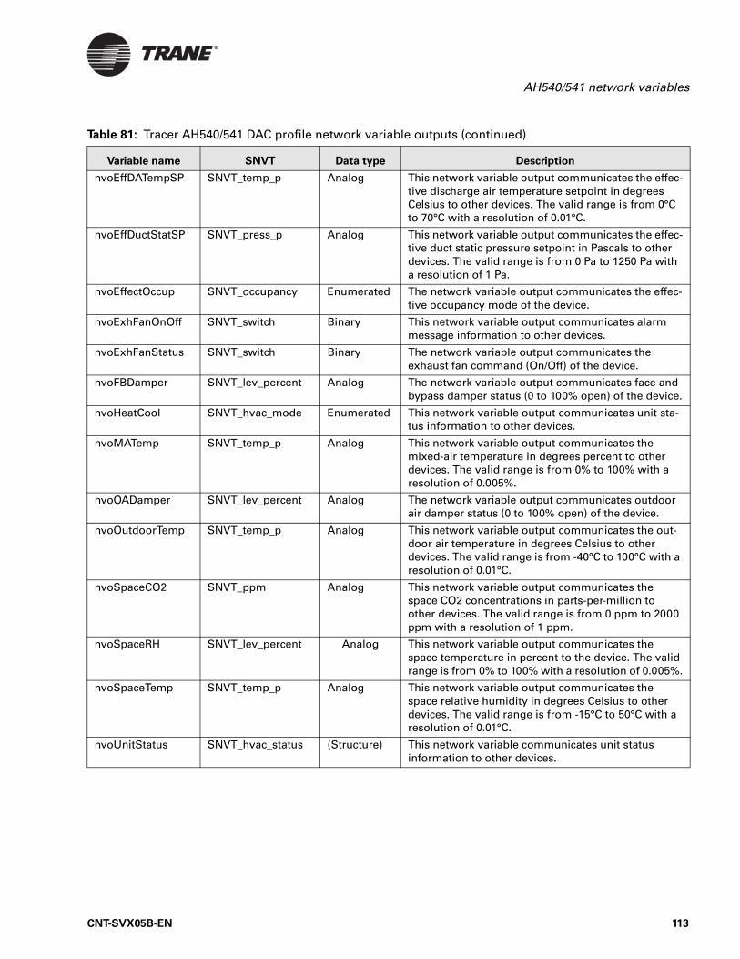
AH540/541 network variables
nvoEffDATempSP SNVT_temp_p Analog This network variable output communicates the effec-tive discharge air temperature setpoint in degrees Celsius to other devices. The valid range is from 0°C to 70°C with a resolution of 0.01°C.
nvoEffDuctStatSP SNVT_press_p Analog This network variable output communicates the effec-tive duct static pressure setpoint in Pascals to other devices. The valid range is from 0 Pa to 1250 Pa with a resolution of 1 Pa.
nvoEffectOccup SNVT_occupancy Enumerated The network variable output communicates the effec-tive occupancy mode of the device.
nvoExhFanOnOff SNVT_switch Binary This network variable output communicates alarm message information to other devices.
nvoExhFanStatus SNVT_switch Binary The network variable output communicates the exhaust fan command (On/Off) of the device.
nvoFBDamper SNVT_lev_percent Analog The network variable output communicates face and bypass damper status (0 to 100% open) of the device.
nvoHeatCool SNVT_hvac_mode Enumerated This network variable output communicates unit sta-tus information to other devices.
nvoMATemp SNVT_temp_p Analog This network variable output communicates the mixed-air temperature in degrees percent to other devices. The valid range is from 0% to 100% with a resolution of 0.005%.
nvoOADamper SNVT_lev_percent Analog The network variable output communicates outdoor air damper status (0 to 100% open) of the device.
nvoOutdoorTemp SNVT_temp_p Analog This network variable output communicates the out-door air temperature in degrees Celsius to other devices. The valid range is from -40°C to 100°C with a resolution of 0.01°C.
nvoSpaceCO2 SNVT_ppm Analog This network variable output communicates the space CO2 concentrations in parts-per-million to other devices. The valid range is from 0 ppm to 2000 ppm with a resolution of 1 ppm.
nvoSpaceRH SNVT_lev_percent Analog This network variable output communicates the space temperature in percent to the device. The valid range is from 0% to 100% with a resolution of 0.005%.
nvoSpaceTemp SNVT_temp_p Analog This network variable output communicates the space relative humidity in degrees Celsius to other devices. The valid range is from -15°C to 50°C with a resolution of 0.01°C.
nvoUnitStatus SNVT_hvac_status (Structure) This network variable communicates unit status information to other devices.
Table 81: Tracer AH540/541 DAC profile network variable outputs (continued)
Variable name SNVT Data type Description
CNT-SVX05B-EN 113

Appendix
114 CNT-SVX05B-EN
CNT-SVX05B-EN
Index
A
AH540overview, 1termination board drawing, 5
AH541overview, 1termination board drawing, 6
air-handling unitssupported configuration options, 1supported function options, 1supported types, 1
analog inputsCO2 sensor (IN13), 21configuration, 76discharge air temperature (IN4), 19duct static pressure (J43), 22entering water temperature (IN13), 21evaporator refrigerant temperature
(IN13), 22fan (supply) mode switch (IN3), 19functions and locations, 17generic temperature (IN13), 22local setpoint (IN2), 18mixed-air temperature (IN6), 20outdoor air temperature (IN5), 19relative humidity (IN13), 20required for unit operation, 88space temperature (IN1), 18universal (IN13), 20
analog outputsconfiguration, 75cool valve output or two-pipe
changeover (AO2), 16face-and-bypass damper (AO4), 16functions and locations, 16heat (water, steam, electric heat
sequencer) (AO3), 16not used (AO6), 16outdoor air damper (AO5), 16ranges, 17supply fan speed (AO1), 16
Auto modedischarge air temperature control, 40space temperature control, 34
B
binary inputscoil defrost (IN12), 27
configuration, 76exhaust fan (IN12), 27filter status (IN11), 26functions and locations, 23generic (IN9), 25occupancy input (IN9), 25run/stop input (IN8), 25supply fan status input (IN10), 26
binary outputsconfiguration, 75DX stage 1/electric stage 4 (BO3), 15DX stage 2/electric stage 3 (BO4), 15DX stage 3/electric stage 2 (BO5), 15DX stage 4/electric stage 1 (BO6), 15exhaust fan start/stop (BO2), 15functions and locations, 15LEDs, 86status LED, 16supply fan start/stop (BO1), 15wiring, 15
binding controllers, 3brightness, adjusting operator display,
13bypass timer, 29
C
calibratinglocal setpoint, 19operator display, 13space temperature input, 18
Cancel button, 18, 23, 29, 47cascade control. See space temperature
control.changeover, 53
space temperature control, 34, 35circuit board drawings, 4, 5, 6CO2 sensor
input (IN13), 21mA values, 108
CO2 Sensor Failure diagnostic, 21, 92coil defrost
as unit protection strategy, 70input (IN7, IN12), 24, 27, 66
coil freeze protectionface-and-bypass heating, 70freeze avoidance, 70low-temperature detection, 70mixed-air temperature control, 70
Comm LED, 88communicated heating/cooling request
115
Index
discharge air temperature control, 39
space temperature control, 33communication
as peer controllers, 3jack on zone sensor, 29status indicators, 83
configurationanalog inputs, 76analog outputs, 75binary inputs, 76binary outputs, 75coil defrost input, 24control mode, 73cooling source, 74daytime warm-up setpoint, 79dehumidification, 77diagnostic alarm level, 81discharge air temperature control
setpoint, 79duct static pressure setpoint and
limit, 79DX cooling, 77entering water temperature
sampling, 80exhaust fan status input, 27face-and-bypass heat modulation,
80fan status input, 26filter status input, 27freeze avoidance setpoint, 80freeze avoidance valve, 80heating, 74local zone sensor fan switch, 78mixed-air temperature control, 79outdoor air damper, 77overview, 73run/stop input, 25sequencer, 81space temperature setpoint and
limit configuration, 78supply fan heating source, 74supply fan status ignore time, 80supported air-handling unit types,
1table of controller function
options, 2table of unit configuration options,
2timer, 81unit operation, 73
conformance, agency, 7connecting portable operator
display, 11connector for stand-alone operator
display, 10constant-volume
air-handler configuration, 73supply fan operation, 50
contrast, adjusting operator display, 13
control loop for space temperature control, 32
control modesconfiguration, 73discharge air temperature, 31, 38space temperature, 31
controller (main) board drawing, 4controller function options, table of,
2cool valve output, 16cool-down, 49cooling operation
space temperature control, 35cooling source configuration, 74
D
DAC. See Discharge Air Controller (DAC) profile.
damper operationface-and-bypass, 55outdoor air, 56
data sharing, 3date and time, set up on operator
display, 12daytime warm-up
operation, 48setpoint configuration, 79
defrost operation, 65coil defrost input, 66evaporator refrigerant
temperature, 65dehumidification
configuration, 77cooling and reheat, 69cooling only, 69occupied and unoccupied mode,
68reheat only, 69
diagnosticsalarm level configuration, 81CO2 Sensor Failure, 21, 92Dirty Filter, 92Discharge Air Temp Failure, 19Duct Static Press Failure, 22, 51, 92Duct Static Press High Limit, 51Entering Water Temp Failure, 21,
92Evap Refrigerant Temp Failure, 22,
92Exhaust Fan Air Flow, 60Generic Temperature Failure, 22,
92Humidity Input Failure, 21, 92interpreting multiple, 90interpretive table, 91Local Fan Switch Failure, 92Local Space Setpoint Failure, 92Low Exhaust Fan Air Flow, 27Low Supply Fan Air Flow, 26, 50
Low Temp Detect, 24, 92Low Temperature Detect, 24Maintenance Required, 70, 92Mixed Air Temperature Failure, 20Outdoor Air Temp Failure, 20resetting, 89Setpoint Failure, 18Space Temperature Failure, 18, 92types, 89Unit Shutdown, 25
differential pressure switchfilter status, 26supply fan status, 26
Dirty Filter diagnostic, 92Discharge Air Controller (DAC)
profileconformance, 1, 31network variable inputs, 111network variable outputs, 112
Discharge Air Temp Failure diagnostic, 19, 91
discharge air temperature controlAuto mode, 40based on effective heat/cool
output, 103communicated heating/cooling
request, 39communicated values, 39configuration, 73configuration parameters, 39cool-down, 49daytime warm-up, 48Discharge Air Controller (DAC)
profile, 31Discharge Air Controller (DAC)
profile network variable inputs, 111
Discharge Air Controller (DAC) profile network variable outputs, 112
flow diagram, 38heating/cooling mode control, 39limits, 38morning warm-up, 48occupied mode, 41operation based on effective
heat/cool output, 103sequence of operations, 38setpoint configuration, 79unoccupied mode, 42variable-air-volume supply fan, 51
discharge air temperature input, 19Duct Static Press Failure diagnostic,
22, 51, 91, 92Duct Static Press High Limit
diagnostic, 51, 91duct static pressure
control sequence, 51high limit, 70input, 22
116 CNT-SVX05B-EN
Index
setpoint and limit configuration, 79
DX cooling, 24coil defrost input, 66compressor circuit wiring, 67configuration, 77defrost operation, 65evaporator refrigerant
temperature, 65evaporator refrigerant
temperature effect, 66overview, 64split-system applications, 66stage output, 15troubleshooting, 98
DX split-system coolingapplications, 66compressor stages and circuits, 66frost protection, 67minimum on/off timers, 67
E
economizing, 20, 59electric heat operation
discharge air temperature control, 61
overview, 60space temperature control, 61troubleshooting, 99
electric heat, stagedbinary output functions and
locations, 15configuration, 74DX cooling, 65overview, 61using binary outputs, 61using sequencer, 62
emergency override, 71Emergency Override diagnostic, 91Entering Water Temp Failure
diagnostic, 21, 92entering water temperature
input, 21two-pipe changeover, 53
entering water temperature sampling
configuration, 80flowchart, 105operation, 53three-way valve applications, 53two-way valve applications, 54
Evap Refrigerant Temp Failure diagnostic, 22, 92
evaporator refrigerant temperatureeffect on DX cooling, 66input (IN13), 22operation, 65
Exhaust Fan Air Flow diagnostic, 60exhaust fan. See fan (exhaust)
F
face-and-bypassanalog output (AO4), 16damper operation, 55heat modulation, 80heating, 70
fan (exhaust)operation, 59start/stop output (BO2), 15status input (IN12), 27
fan (supply)constant-volume operation, 50general operation, 50ignore time configuration of status
input, 80mode switch input, 19mode switch on zone sensor, 28motor thermal protection, 70speed output, 16status, 70status input, 26troubleshooting, 93variable-air-volume operation, 51
fan (supply)/heat sourceblow-through, 74draw-through, 74
filter status, 70input (IN11), 26
free cooling. See economizingfreeze avoidance, 70
setpoint configuration, 80valve configuration, 80valve cycling, 52
freezestat, 24
G
generic binary input (IN9), 25, 26Generic Temperature Failure
diagnostic, 22, 92generic temperature input, 22
H
heat output (water, steam, electric heat sequencer), 16
heat/cool changeover operationspace temperature control, 34, 35
heating operationconfiguration, 74space temperature control, 36
heating/cooling mode controldischarge air temperature, 39space temperature, 32
heating/cooling operation, two-pipe changeover, 53
humidity
input, 20sensor, 20sensor mA values, 107
Humidity Input Failure diagnostic, 21, 92
I
installing stand-alone operator display, 9
Internal setpoint adjustment, 36Invalid Unit Configuration
diagnostic, 91
L
LEDsbinary outputs (green), 86Comm (yellow), 88interpreting, 86Service (red), 87Status (green), 87
Local Fan Switch Failure diagnostic, 92
local occupancy mode request, 25local setpoint input, 18Local Space Setpoint Failure
diagnostic, 92local zone sensor fan switch
configuration, 78location label, 74location of
LEDs, 83Service Pin button, 83Test button, 83
LonMark profileDischarge Air Controller (DAC), 1Space Comfort Controller (SCC), 1
Low Exhaust Fan Air Flow diagnostic, 27, 91
Low Supply Fan Air Flow diagnostic, 26, 50, 91
Low Temp Detect diagnostic, 24, 91, 92
low-temperature detectionas unit protection strategy, 70device (freezestat), 24input, 24
M
Maintenance Required diagnostic, 70, 92
manual output testas protection strategy, 71performing, 84sequence, 85
Manual Output Test diagnostic, 91
CNT-SVX05B-EN 117
Index
minimum On/Off timers, 70Mixed Air Temp Failure diagnostic,
20, 91Mixed Air Temperature Failure
diagnostic, 20mixed-air temperature
hard-wired 1kohm sensor RTD values, 107
input (IN6), 20limits, 79sensor location, 58
mixed-air temperature controlas unit protection strategy, 70configuration, 79operation, 57
modes of operationdischarge air temperature control,
31space temperature control, 31
N
network variablesgeneral, 109inputs defined, 109inputs, DAC profile, 111inputs, SCC profile, 109outputs defined, 109outputs, DAC profile, 112outputs, SCC profile, 110
nvi, 109nviApplicMode, 101, 103nviHeatCool, 101nvo, 109nvoApplicMode, 103nvoEffectOccup, 45nvoHeatCool, 101, 103
O
occupancy inputhow controller uses, 44local occupancy mode request, 25location (IN9), 25
occupancy modescontrolling the mode, 43description of valid, 41determining by manual command,
44determining by network variable
input, 45determining by sensor request, 45local request, 25occupied, 41occupied bypass, 43occupied standby, 42sources of control, 43unoccupied, 41
occupied bypass mode, 18, 29, 43
occupied modedischarge air temperature control,
41space temperature control, 41
occupied standby mode, 42On button, 18, 23, 29, 47operation status indicators, 83operator display
adjusting brightness and contrast, 13
calibrating, 13cleaning, 9connecting portable, 11installing stand-alone, 9security password, setting up,
changing, disabling, 14setting up, 12setting up time and date, 12setting up, overview, 12
outdoor air damperconfiguration, 77lockout, 59minimum position setpoint, 56mixed-air temperature control, 57occupied minimum position, 56operation, 56, 58output (AO5), 16troubleshooting, 96, 97
Outdoor Air Temp Failure diagnostic, 20, 91
outdoor air temperature input, 19override request, 29overrides
emergency, 71manual output test, 71water valve, 72
P
passwordsetting up, changing, disabling, 14
portable operator display, 11power requirements, 7power-up control wait, 40power-up sequence, 40priority control table, 45purge. See entering water
temperature sampling
R
relative humidity. See humidity.resetting diagnostics, 89
building automation system, 90cycling power, 89diagnostic reset input, 90manual output test, 89operator display, 90Rover service tool, 90
zone sensor fan mode switch, 90Rover service tool
for binding controllers, 3for configuring the controller, 15,
73for manual output test, 71for resetting diagnostics, 90
run/stop input, 25, 70
S
SCC. See Space Comfort Controller (SCC) profile.
scheduling, 11security password, 14sequence of operations
discharge air temperature control, 38
occupancy modes, 41power-up, 40space temperature control, 31space temperature setpoint
arbitration, 36sequencer
configuration, 81for staged electric heat, 62
Service LED, 87Service Pin button, 86Service Pin message request, 29, 86setpoint
arbitration, 36limits, 37
Setpoint Failure diagnostic, 18setting up
operator display, 12Space Comfort Controller (SCC)
profileconformance, 1network variable outputs, 110network variables inputs, 109
space temperatureinput (IN1), 18measuring using a zone sensor, 28setpoint and limit configuration,
78space temperature control
Auto mode, 34block diagram, 33communicated heating/cooling
request, 33communicated request, 33configuration, 73constant-volume supply fan, 50control loop, 32cool-down, 49cooling operation, 35heat/cool changeover, 35heating operation, 36heating/cooling mode, 32measuring using a zone sensor, 18
118 CNT-SVX05B-EN
Index
morning warm-up, 47occupied mode, 41operation based on effective
heat/cool output, 101sequence of operations, 31setpoint adjustment, 36setpoint arbitration, 36Space Comfort Controller (SCC)
profile, 31Space Comfort Controller (SCC)
profile network variable inputs, 109
Space Comfort Controller (SCC) profile network variable outputs, 110
unoccupied mode, 42Space Temperature Failure
diagnostic, 18, 91, 92specifications
agency conformance, 7dimensions, 7operating environment, 7power requirements, 7storage environment, 7
staged electric heatconfiguration, 74DX cooling, 65sequencer configuration, 81using binary outputs, 61using sequencer, 62
stand-alone operation, 3stand-alone operator display, 9Status LED, 87supply fan. See fan (supply).
T
termination board drawingAH540, 5AH541, 6
Test button, 83thermistor values, hard-wired 10
kohms, 106thermostat. See zone sensor.time and date, setting up on
operator display, 12time clock, 11timed override, 29, 47
On and Cancel requests, 18timer
configuration, 81minimum On/Off, 70minimum On/Off for DX split-
system cooling, 67troubleshooting
binary output LEDs, 86Comm LED, 88DX cooling binary outputs do not
energize, 98
electric heat binary outputs do not energize, 99
fans do not energize, 93manual output test, 84outdoor air damper stays closed,
97outdoor air damper stays open, 96required inputs for unit operation,
88Service LED, 87Service Pin button, 86Status LED, 87Test button, 83valves stay closed, 95valves stay open, 94
two-pipe changeover, 16, 53, 60
U
unit configuration options, table of, 1, 2
unit protection, strategies for, 70Unit Shutdown diagnostic, 25, 91unit type configuration, 73universal analog input (IN13), 20unoccupied mode
discharge air temperature control, 42
space temperature control, 42
V
valvesfreeze avoidance, 52operation, 52override water, 72troubleshooting, 94, 95
valves, three-wayentering water temperature
sampling, 53valves, two-way
entering water temperature sampling, 54
variable-air-volumeair-handler configuration, 73supply fan operation, 51
Version 1 and 2hardware and firmware
differences, 1
W
warm-updaytime, 48morning, 47
water valve override, 72wiring connections for zone sensor,
29
wiring stand-alone operator display, 9
Z
zone sensorcommunication jack, 29fan (supply) mode switch, 28hard-wired setpoint adjustment,
106inputs, 28On/Cancel buttons, 18, 23, 29, 47Service Pin message, 29setpoint adjustment, 28setpoint thumbwheel, 36space temperature measuring, 28timed override option, 47wiring connections, 29
CNT-SVX05B-EN 119

Index
120 CNT-SVX05B-EN
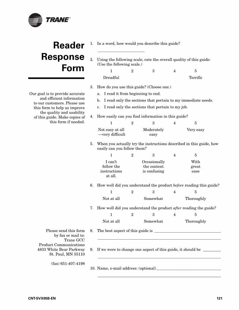
Reader
Response
Form
1. In a word, how would you describe this guide?
________________________
2. Using the following scale, rate the overall quality of this guide: (Use the following scale.)
1 2 3 4 5
Dreadful Terrific
3. How do you use this guide? (Choose one.)
a. I read it from beginning to end.
b. I read only the sections that pertain to my immediate needs.
c. I read only the sections that pertain to my job.
4. How easily can you find information in this guide?
1 2 3 4 5
Not easy at all Moderately Very easy —very difficult easy
5. When you actually try the instructions described in this guide, how easily can you follow them?
1 2 3 4 5
I can’t Occasionally Withfollow the the content great
instructions is confusing easeat all.
6. How well did you understand the product before reading this guide?
1 2 3 4 5
Not at all Somewhat Thoroughly
7. How well did you understand the product after reading the guide?
1 2 3 4 5
Not at all Somewhat Thoroughly
8. The best aspect of this guide is __________________________________
_______________________________________________________________
9. If we were to change one aspect of this guide, it should be _________
_______________________________________________________________
10. Name, e-mail address: (optional)_________________________________
_______________________________________________________________
Our goal is to provide accurateand efficient information
to our customers. Please usethis form to help us improve
the quality and usabilityof this guide. Make copies of
this form if needed.
Please send this formby fax or mail to:
Trane GCCProduct Communications
4833 White Bear ParkwaySt. Paul, MN 55110
(fax) 651-407-4198
CNT-SVX05B-EN 121

Reader Response Form
122 CNT-SVX05B-EN


Trane has a policy of continuous product and product data improvement and reserves the right to change design and specifications without notice. Only qualified technicians should perform the installa-tion and servicing of equipment referred to in this publication.
Literature Order Number CNT-SVX05B-EN
File Number SV-ES-CNT-SVX-05B-EN-0404
Supersedes CNT-SBX05A-EN
Stocking Location InlandTraneA business of American Standard Companieswww.trane.com
For more information, contact your local Trane office or e-mail us at [email protected]


![ModBusTCP Setup&Operation Manual [B-82844EN 01]](https://img.pdfslide.net/doc/110x75/55cf85cb550346484b91639f/modbustcp-setupoperation-manual-b-82844en-01.jpg)