Embed Size (px)
Citation preview
SETUP AND USER GUIDEMediaAccess TC8715


SAFETY INSTRUCTIONSAND REGULATORY NOTICES
Before you start installation or use of this product, carefully read these instructions!
DirectiveUnless express and prior approval by Technicolor in writing, you may not: Disassemble, de-compile, reverse engineer, trace or otherwise analyse the equipment,
its content, operation, or functionality,or otherwise attempt to derive source code (or the underlying ideas, algorithms, structure or organization) from the equipment,or from any other information provided by Technicolor, except to the extent that this restriction is expressly prohibited by local law;
Copy, rent, loan, re-sell, sub-license, or otherwise transfer or distribute the equipment to others;
Modify, adapt or create a derivative work of the equipment; Remove from any copies of the equipment any product identification, copyright or
other notices; Disseminate performance information or analysis (including, without limitation,
benchmarks) from any source relating to the equipment.Such acts not expressly approved by Technicolor will result in the loss of product warranty and may invalidate the user's authority to operate this equipment in accordance with FCC Rules.Technicolor disclaims all responsibility in the event of use that does not comply with the present instructions.
Safety instructionsClimatic conditions
This product: Is intended for in-house stationary desktop use; the maximum ambient temperature
may not exceed 40°C (104°F). Must not be mounted in a location exposed to direct or excessive solar and/or heat
radiation. Must not be exposed to heat trap conditions and must not be subjected to water or
condensation. Batteries (battery pack or batteries installed) shall not be exposed to excessive heat such as sunshine, fire or the like.
Must be installed in a Pollution Degree 2 environment (Environment where there is no pollution or only dry, nonconductive pollution).
Cleaning
Unplug this product from the wall socket and computer before cleaning. Do not use liquid cleaners or aerosol cleaners. Use a damp cloth for cleaning.
Water and moisture
Do not use this product near water, for example near a bathtub, washbowl, kitchen sink, laundry tub, in a wet basement or near a swimming pool. Transition of the product from a cold environment to a hot one may cause condensation on some of its internal parts. Allow it to dry by itself before re-starting the product.
Secure handling and disposal of used batteries
NOTE: Only use the battery qualified for this equipment.Remember to dispose batteries properly according to local regulation, i.e. at a battery collection point. Batteries may not be disposed with domestic waste.
Interface classifications
The external interfaces of the product are classified as follows: Phone: TNV circuit, not subjected to over voltages (TNV-2) Cable, RF: TNV circuit subject to overvoltages (TNV-1) All other interface ports (e.g. Ethernet, USB, etc.), including the low voltage power
input from the AC mains power supply: SELV circuits.
Electrical powering
The powering of the product must adhere to the power specifications indicated on the marking labels.
USB
The device is to be connected to an identified USB port complying with the requirements of a Limited Power Source.
Accessibility
The plug on the power supply cord serves as disconnect device. Be sure that the power socket outlet you plug the power cord into is easily accessible and located as close to the equipment as possible.
Overloading
Do not overload mains supply socket outlets and extension cords as this increases the risk of fire or electric shock.
Servicing
To reduce the risk of electric shock, do not disassemble this product. None of its internal parts are user-replaceable; therefore, there is no reason to access the interior. Opening or removing covers may expose you to dangerous voltages. Incorrect reassembly could cause electric shock if the appliance is subsequently used.
If service or repair work is required, take it to a qualified service dealer.
Damage requiring service
Unplug this product from the wall outlet and refer servicing to qualified service personnel under the following conditions: When the power supply or its plug are damaged. When the attached cords are damaged or frayed. If liquid has been spilled into the product. If the product has been exposed to rain or water. If the product does not operate normally. If the product has been dropped or damaged in any way. There are noticeable signs of overheating. If the product exhibits a distinct change in performance.Immediately disconnect the product if you notice it giving off a smell of burning or smoke. Under no circumstances must you open the equipment yourself; you run the risk of electrocution.
Regulatory informationYou must install and use this device in strict accordance with the manufacturer's instructions as described in the user documentation that is included with your product.Before you start installation or use of this product, carefully read the contents of this document for device specific constraints or rules that may apply in the country where you want to use this product.In some situations or environments, the use of wireless devices may be restricted by the proprietor of the building or responsible representatives of the organization.If you are uncertain of the policy that applies on the use of wireless equipment in a specific organization or environment (e.g. airports), you are encouraged to ask for authorization to use this device prior to turning on the equipment.Technicolor is not responsible for any radio or television interference caused by unauthorized modification of the device, or the substitution or attachment of connecting cables and equipment other than specified by Technicolor. The correction of interference caused by such unauthorized modification, substitution or attachment will be the responsibility of the user.Technicolor and its authorized resellers or distributors are not liable for any damage or violation of government regulations that may arise from failing to comply with these guidelines.
North-America - United States of AmericaImportant safety instructions
The cable distribution system should be grounded (earthed) in accordance with ANSI/NFPA 70, the National Electrical Code (NEC), in particular Section 820,93, Grounding of outer Conductive Shield of a Coaxial Cable.
Leave 5 to 8 cm (2 to 3 inches) around the product to ensure proper ventilation to it. Never push objects through the openings in this product.
Federal Communications Commission (FCC) radio frequency interference statement
This equipment has been tested and found to comply with the limits for a Class B digital device, pursuant to Part 15 of the FCC Rules. These limits are designed to provide reasonable protection against harmful interference in a residential installation. This equipment generates, uses and can radiate radio frequency energy and, if not installed and used in accordance with the instructions, may cause harmful interference to radio communications. However, there is no guarantee that interference will not occur in a particular installation. If this equipment does cause harmful interference to radio or television reception, which can be determined by turning the equipment off and on, the user is encouraged to try to correct the interference by one or more of the following measures: Reorient or relocate the receiving antenna. Increase the separation between the equipment and receiver. Connect the equipment into an outlet on a circuit different from that to which the
receiver is connected. Consult the dealer or an experienced radio/TV technician for help.
RF-exposure statement
When the product is equipped with a wireless interface, then it becomes a mobile or fixed mounted modular transmitter and must have a separation distance of at least 20 cm (8 inches) between the antenna and the body of the user or nearby persons. In practice, this means that the user or nearby persons must have a distance of at least 20 cm (8 inches) from the modem and must not lean on the modem in case it is wall-mounted.With a separation distance of 20 cm (8 inches) or more, the M(aximum) P(ermissible) E(xposure) limits are well above the potential this module is capable to produce.For operation within 5.15 ~ 5.25GHz frequency range, it is restricted to indoor environment. This device meets all the other requirements specified in Part 15E, Section 15.407 of the FCC Rules.This transmitter must not be co-located or operating in conjunction with any other antenna or transmitter.
Restricted frequency band
This product is equipped with an IEEE802.11b/IEEE802.11g/IEEE802.11n wireless transceiver and may only use channels 1 to 11 (2412 to 2462 MHz) on U.S.A. territory.
!When using this product, always follow the basic safety precautions to reduce the risk of fire, electric shock and injury to persons, including the following: Always install the product as described in the documentation that is included
with your product. Avoid using this product during an electrical storm. There may be a remote
risk of electric shock from lightning. Do not use this product to report a gas leak in the vicinity of the leak.
This device complies with Part 15 of the FCC Rules. Operation is subject to the following two conditions:1 This device may not cause harmful interference, and2 This device must accept any interference received, including
interference that may cause undesired operation.
SETUP AND USER GUIDEMediaAccess TC8715
Copyright
Copyright ©1999-2015 Technicolor. All rights reserved.
Distribution and copying of this document, use and communication of its contents is not permitted without written authorization from Techni-color. The content of this document is furnished for informational use only, may be subject to change without notice, and should not be construed as a commitment by Technicolor. Technicolor assumes no responsibility or liability for any errors or inaccuracies that may appear in this document.
TECHNICOLOR WORLDWIDE HEADQUARTERS1-5 rue Jeanne d’Arc92130 Issy les MoulineauxFrance
http://www.technicolor.com
Trademarks
The following trademarks may be used in this document:
AutoWAN sensing™ is a trademark of Technicolor.
Qeo™ is a trademark of Qeo LLC, a subsidiary of Technicolor.
Adobe®, the Adobe logo, Acrobat® and Adobe Reader® are trademarks or registered trademarks of Adobe Systems, Incorporated, regis-tered in the United States and/or other countries.
Apple® and Mac OS® are registered trademarks of Apple Computer, Incorporated, registered in the United States and other countries.
Bluetooth® word mark and logos are owned by the Bluetooth SIG, Inc.
CableLabs® and DOCSIS® are registered trademarks of CableLabs, Inc.
DECT™ is a trademark of ETSI.
DLNA® is a registered trademark, DLNA disc logo is a service mark, and DLNA Certified™ is a trademark of the Digital Living Network Alliance. Digital Living Network Alliance is a service mark of the Digital Living Network Alliance.
Ethernet™ is a trademark of the Xerox Corporation.
EuroDOCSIS™, EuroPacketCable™ and PacketCable™ are trademarks of CableLabs, Inc.
HomePNA™ and HPNA™ are trademarks of HomePNA, Inc.
Linux™ is a trademark of Linus Torvalds.
Microsoft®, MS-DOS®, Windows®, Windows NT® and Windows Vista® are either registered trademarks or trademarks of the Microsoft Corporation in the United States and/or other countries.
MoCA® and the MoCA logo are registered trademarks of the Multimedia over Coax Alliance.
UNIX® is a registered trademark of UNIX System Laboratories, Incorporated.
UPnP™ is a certification mark of the UPnP Implementers Corporation.
Wi-Fi Alliance®, Wi-Fi®, WMM® and the Wi-Fi logo are registered trademarks of the Wi-Fi Alliance. Wi-Fi CERTIFIED™, Wi-Fi ZONE™, Wi-Fi Protected Access™, Wi-Fi Multimedia™, Wi-Fi Protected Setup™, WPA™, WPA2™ and their respective logos are trademarks of the Wi-Fi Alliance.
Other brands and product names may be trademarks or registered trademarks of their respective holders. All other logos, trademarks and service marks are the property of their respective owners, where marked or not.
Document Information
Status: v1.0 (May 2015)Reference: DMS3-CTC-25-114 Short Title: Setup and User Guide MediaAccess TC8715
i
CONTENTS
DMS3-CTC-25-114 v1.0
About this Setup and User Guide ..................................................................................1
1 Getting started.......................................................................................................... 3
1.1 Features at a glance .................................................................................................................................. 4
1.2 Getting to know the MediaAccess Gateway......................................................................................... 51.2.1 Front panel ...................................................................................................................................................................... 61.2.2 Top panel ....................................................................................................................................................................... 81.2.3 Back panel ....................................................................................................................................................................... 91.2.4 Bottom panel ................................................................................................................................................................. 11
1.3 Preparing for the installation................................................................................................................... 12
2 Setup ........................................................................................................................ 13
2.1 Connect the MediaAccess Gateway to your service provider’s network..........................................14
2.2 Power on the MediaAccess Gateway....................................................................................................15
2.3 Connect your wired devices....................................................................................................................16
2.4 Connect your wireless devices................................................................................................................ 172.4.1 How to connect your wireless client via WPS............................................................................................................182.4.2 How to manually connect your wireless client ..........................................................................................................20
3 Admin Tool ............................................................................................................. 25
3.1 Components ............................................................................................................................................ 26
3.2 How to change the default Admin Tool password ............................................................................. 28
3.3 How to backup or restore a configuration ........................................................................................... 29
4 The MediaAccess Gateway wireless access point ...................................................31
4.1 How to configure the wireless settings ..................................................................................................32
4.2 How to start a WPS session via the Admin Tool ................................................................................ 34
4.3 Prevent devices from accessing your wireless network....................................................................... 36
5 Sharing content ........................................................................................................37
5.1 The network file server ........................................................................................................................... 39
5.2 The UPnP AV media server ...................................................................................................................41
6 Internet security ...................................................................................................... 43
6.1 Parental control ....................................................................................................................................... 446.1.1 Manage sites ................................................................................................................................................................. 456.1.2 Manage services ........................................................................................................................................................... 476.1.3 Manage devices............................................................................................................................................................496.1.4 View parental control reports ......................................................................................................................................51
6.2 Firewall...................................................................................................................................................... 52
ii
CONTENTS
DMS3-CTC-25-114 v1.0
7 Advanced configuration.......................................................................................... 53
7.1 Port configuration for applications and services.................................................................................. 547.1.1 UPnP.............................................................................................................................................................................. 567.1.2 Port forwarding............................................................................................................................................................. 587.1.3 Port triggering ..............................................................................................................................................................607.1.4 Configure a DMZ Host............................................................................................................................................... 62
7.2 Assigning a reserved IP to a device ...................................................................................................... 63
8 Support.................................................................................................................... 65
8.1 Wireless connection troubleshooting ................................................................................................... 66
8.2 Network diagnostic tools........................................................................................................................ 69
8.3 MediaAccess Gateway reset and restore options............................................................................... 70
1
ABOUT THIS SETUP AND USER GUIDE
DMS3-CTC-25-114 v1.0
About this Setup and User Guide
In this Setup and User Guide
The goal of this Setup and User Guide is to show you:
Set up your MediaAccess Gateway and local network
Configure and use the main features of your MediaAccess Gateway.
For more advanced scenarios and features visit the documentation pages on www.technicolor.com.
Used symbols
Terminology
Generally, the MediaAccess TC8715 will be referred to as MediaAccess Gateway in this Setup and User Guide.
Typographical conventions
Following typographical convention is used throughout this manual:
This sample text indicates a hyperlink to a Web site.
Example: For more information, visit us at www.technicolor.com.
This sample text indicates an internal link.
Example: If you want to know more about guide, see “About this Setup and User Guide” on page 1.
This sample text indicates an important content-related word.
Example: To enter the network, you must authenticate yourself.
This sample text indicates a GUI element (commands on menus and buttons, dialog box elements, file names, paths and folders).
Example: On the File menu, click Open to open a file.
The danger symbol indicates that there may be a possibility of physical injury.
The warning symbol indicates that there may be a possibility of equipment damage.
The caution symbol indicates that there may be a possibility of service interruption.
The note symbol indicates that the text provides additional information about a topic.

2
ABOUT THIS SETUP AND USER GUIDE
DMS3-CTC-25-114 v1.0
3
1 GETTING STARTED
DMS3-CTC-25-114 v1.0
1 Getting started
Introduction
This chapter gives you a brief overview of the main features and components of the MediaAccess Gateway. After this chapter we will start with the installation.
Do not connect any cables to the MediaAccess Gateway until instructed to do so.
4
1 GETTING STARTED
DMS3-CTC-25-114 v1.0
1.1 Features at a glance
Introduction
This section provides a brief overview of the main features of your MediaAccess Gateway.
Superior wireless performance
The integrated IEEE 802.11n 2.4 GHz 3x3 and IEEE 802.11ac 5 GHz 3x3 wireless access points are optimized for high-speed video and data transfer over wireless.
Each access point has multiple wireless transmitters and receivers. This allows it to handle multiple data streams at the same time and boost the wireless transmission rate and data stream reliability.
IPv6 Ready
Your MediaAccess Gateway is IPv6 ready. Internet Protocol version 6 (IPv6) is the next generation of Internet technologies aiming to effectively support the ever-expanding Internet usage and functionality, and also to address security concerns that exist in an IPv4 environment.
Internet connection features
Broadband access via the integrated DOCSIS 3.0 16x4 Cable Modem
Parental control allows you to restrict access to specific websites, services or your network.For more information, see “6.1 Parental control” on page 44.
The MediaAccess Gateway has an integrated firewall to protect you from malicious attacks.For more information, see “6.2 Firewall” on page 52.
Advanced network tools like port forwarding, port triggering and DMZ.For more information, see “7 Advanced configuration” on page 53.
Local networking features
Wireless access for your local network devices via the integrated IEEE 802.11b/g/n 2.4 GHz and 5 GHz wireless access points.For more information, see “2.4 Connect your wireless devices” on page 17.
Wired access for your local network devices via the Ethernet interface.For more information, see “2.3 Connect your wired devices” on page 16.
An integrated file and media server allowing you to share your media with media players and other network devices. For more information, see “5 Sharing content” on page 37.
Easy configuration
The Admin Tool allows you to configure your MediaAccess Gateway and network via your web browser.For more information, see “3 Admin Tool” on page 25.
5
1 GETTING STARTED
DMS3-CTC-25-114 v1.0
1.2 Getting to know the MediaAccess Gateway
This section introduces you to the different components of the MediaAccess Gateway:
Topic Page
1.2.1 Front panel 6
1.2.2 Top panel 8
1.2.3 Back panel 9
1.2.4 Bottom panel 11
6
1 GETTING STARTED
DMS3-CTC-25-114 v1.0
1.2.1 Front panel
Introduction
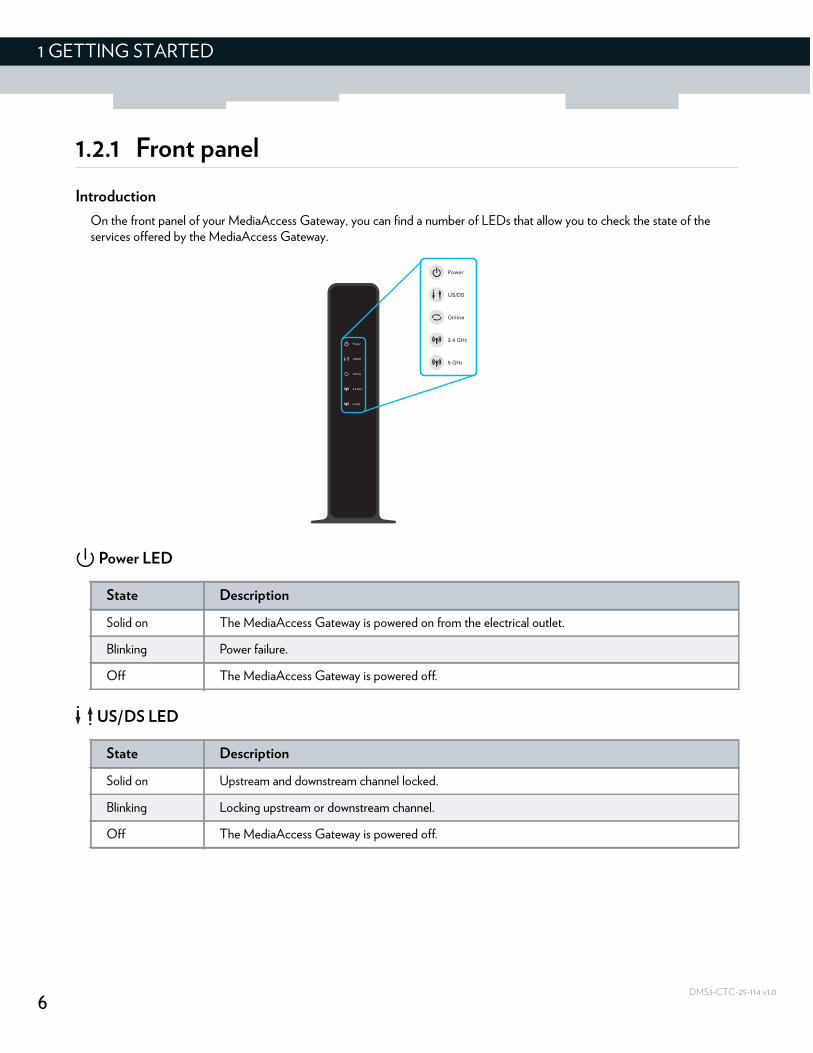
On the front panel of your MediaAccess Gateway, you can find a number of LEDs that allow you to check the state of the services offered by the MediaAccess Gateway.
Power LED
US/DS LED
State Description
Solid on The MediaAccess Gateway is powered on from the electrical outlet.
Blinking Power failure.
Off The MediaAccess Gateway is powered off.
State Description
Solid on Upstream and downstream channel locked.
Blinking Locking upstream or downstream channel.
Off The MediaAccess Gateway is powered off.
7
1 GETTING STARTED
DMS3-CTC-25-114 v1.0
Online LED
2.4 GHz LED
5 GHz LED
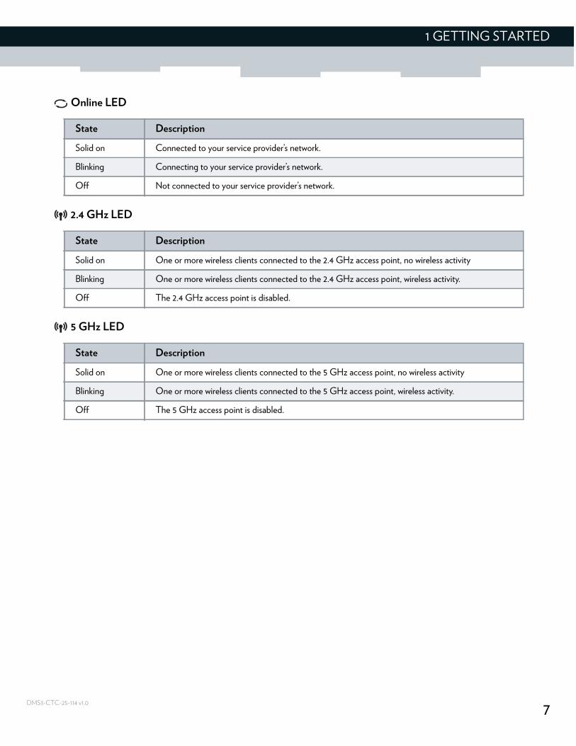
State Description
Solid on Connected to your service provider’s network.
Blinking Connecting to your service provider’s network.
Off Not connected to your service provider’s network.
State Description
Solid on One or more wireless clients connected to the 2.4 GHz access point, no wireless activity
Blinking One or more wireless clients connected to the 2.4 GHz access point, wireless activity.
Off The 2.4 GHz access point is disabled.
State Description
Solid on One or more wireless clients connected to the 5 GHz access point, no wireless activity
Blinking One or more wireless clients connected to the 5 GHz access point, wireless activity.
Off The 5 GHz access point is disabled.
8
1 GETTING STARTED
DMS3-CTC-25-114 v1.0
1.2.2 Top panel
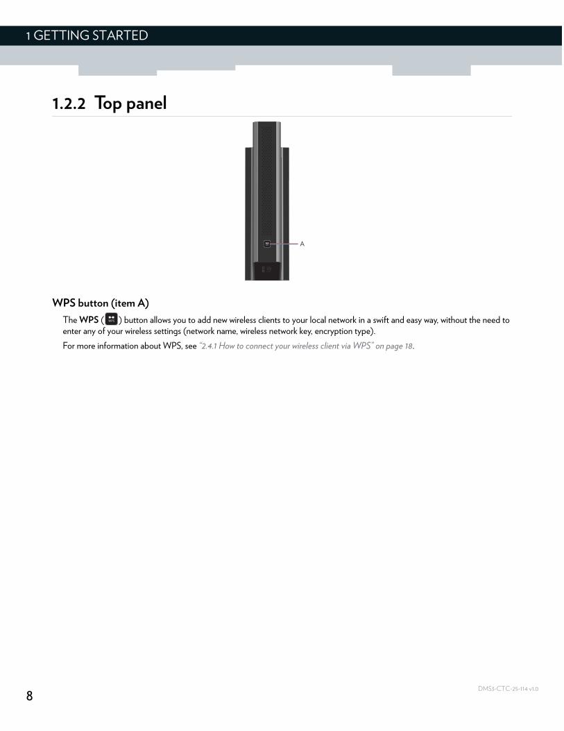
WPS button (item A)
The WPS ( ) button allows you to add new wireless clients to your local network in a swift and easy way, without the need to enter any of your wireless settings (network name, wireless network key, encryption type).
For more information about WPS, see “2.4.1 How to connect your wireless client via WPS” on page 18.
A
9
1 GETTING STARTED
DMS3-CTC-25-114 v1.0
1.2.3 Back panel
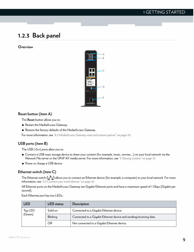
Overview
Reset button (item A)
The Reset button allows you to:
Restart the MediaAccess Gateway.
Restore the factory defaults of the MediaAccess Gateway.
For more information, see “8.3 MediaAccess Gateway reset and restore options” on page 70.
USB ports (item B)
The USB ( ) ports allow you to:
Connect a USB mass storage device to share your content (for example, music, movies,...) on your local network via the Network File server or the UPnP AV media server. For more information, see “5 Sharing content” on page 37.
Power or charge a USB device.
Ethernet switch (item C)
The Ethernet switch ( ) allows you to connect an Ethernet device (for example, a computer) to your local network. For more information, see “2.3 Connect your wired devices” on page 16.
All Ethernet ports on the MediaAccess Gateway are Gigabit Ethernet ports and have a maximum speed of 1 Gbps (Gigabit per second).
Each Ethernet port has two LEDs:.
E
D
C
B
A
LED LED status Description
Top LED(Green)
Solid on Connected to a Gigabit Ethernet device.
Blinking Connected to a Gigabit Ethernet device and sending/receiving data.
Off Not connected to a Gigabit Ethernet device.
10
1 GETTING STARTED
DMS3-CTC-25-114 v1.0
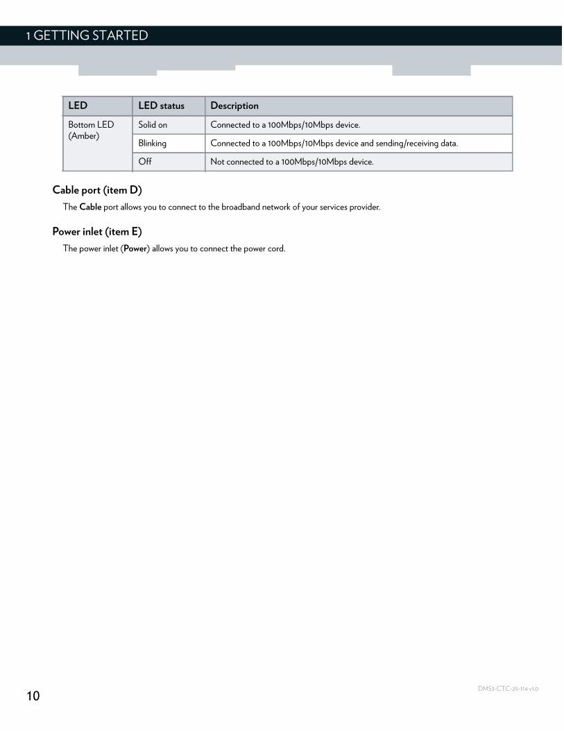
Cable port (item D)
The Cable port allows you to connect to the broadband network of your services provider.
Power inlet (item E)
The power inlet (Power) allows you to connect the power cord.
Bottom LED(Amber)
Solid on Connected to a 100Mbps/10Mbps device.
Blinking Connected to a 100Mbps/10Mbps device and sending/receiving data.
Off Not connected to a 100Mbps/10Mbps device.
LED LED status Description
11
1 GETTING STARTED
DMS3-CTC-25-114 v1.0
1.2.4 Bottom panel
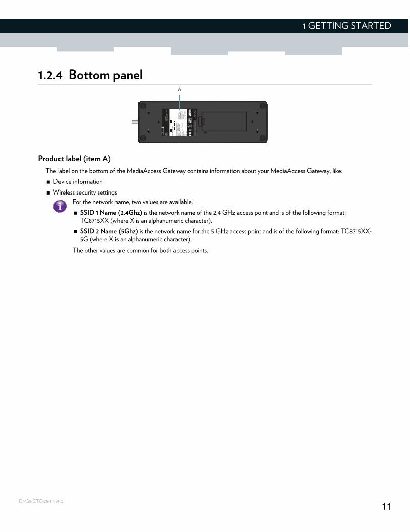
Product label (item A)
The label on the bottom of the MediaAccess Gateway contains information about your MediaAccess Gateway, like:
Device information
Wireless security settings
A
For the network name, two values are available:
SSID 1 Name (2.4Ghz) is the network name of the 2.4 GHz access point and is of the following format: TC8715XX (where X is an alphanumeric character).
SSID 2 Name (5Ghz) is the network name for the 5 GHz access point and is of the following format: TC8715XX-5G (where X is an alphanumeric character).
The other values are common for both access points.
12
1 GETTING STARTED
DMS3-CTC-25-114 v1.0
1.3 Preparing for the installation
Local connection requirements
Wireless connection
If you want to connect your computer using a wireless connection, your computer must be equipped with a Wi-Fi Certified wireless client adapter.
Wired connection
If you want to connect a computer using a wired connection, your computer must be equipped with an Ethernet Network Interface Card (NIC).
Start with the installation
You are now ready to start with the installation of your MediaAccess Gateway, proceed with “2 Setup” on page 13.
13
2 SETUP
DMS3-CTC-25-114 v1.0
2 Setup
Setup procedure
Complete the following steps to setup the MediaAccess Gateway:
1 Connect your MediaAccess Gateway to your service provider’s network.For more information, see “2.1 Connect the MediaAccess Gateway to your service provider’s network” on page 14.
2 Power on the MediaAccess Gateway.For more information, see “2.2 Power on the MediaAccess Gateway” on page 15.
3 Connect your wired devices to the MediaAccess Gateway.For more information, see “2.3 Connect your wired devices” on page 16.
4 Connect your wireless devices to the MediaAccess Gateway.For more information, see “2.4 Connect your wireless devices” on page 17.
Optional configuration
After completing the setup procedure, the MediaAccess Gateway is ready for use. Optionally, you can further configure the MediaAccess Gateway to your needs (for example, change the wireless security) using the MediaAccess Gateway’s Admin Tool.
For more information, see “3 Admin Tool” on page 25.
14
2 SETUP
DMS3-CTC-25-114 v1.0
2.1 Connect the MediaAccess Gateway to your service provider’s network
Introduction
This section helps you to connect the MediaAccess Gateway to your service provider’s network.
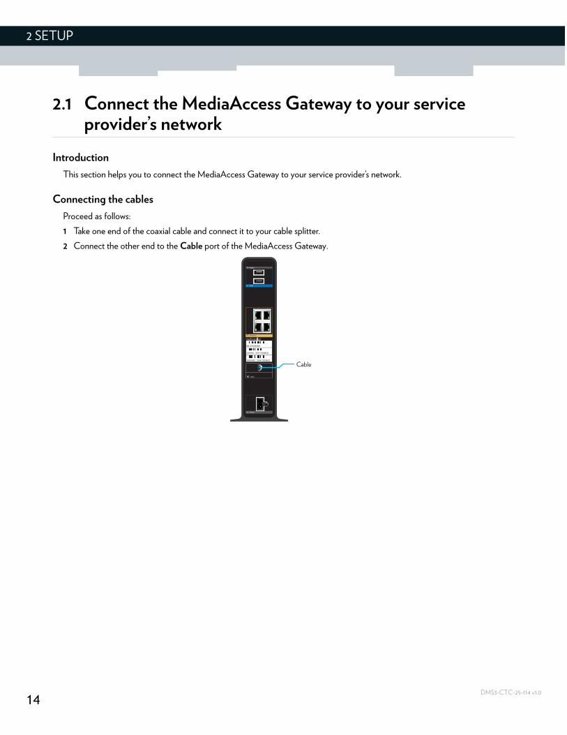
Connecting the cables
Proceed as follows:
1 Take one end of the coaxial cable and connect it to your cable splitter.
2 Connect the other end to the Cable port of the MediaAccess Gateway.
Cable
15
2 SETUP
DMS3-CTC-25-114 v1.0
2.2 Power on the MediaAccess Gateway
Procedure
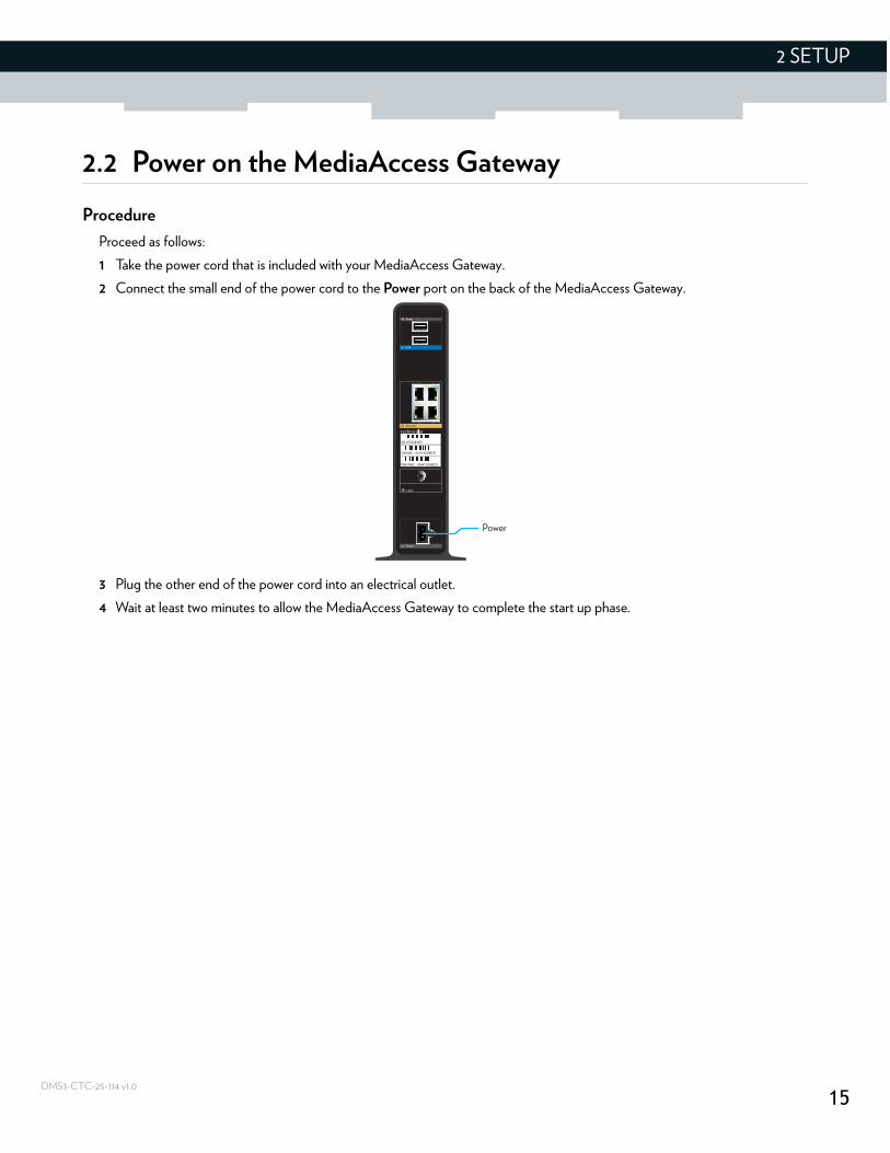
Proceed as follows:
1 Take the power cord that is included with your MediaAccess Gateway.
2 Connect the small end of the power cord to the Power port on the back of the MediaAccess Gateway.
3 Plug the other end of the power cord into an electrical outlet.
4 Wait at least two minutes to allow the MediaAccess Gateway to complete the start up phase.
Power
16
2 SETUP
DMS3-CTC-25-114 v1.0
2.3 Connect your wired devices
Requirements
Both your network device (for example, a computer, a gaming console, etc.) and MediaAccess Gateway must have a free Ethernet port.
Your network device must be configured to obtain an IP address automatically. This is the default setting.
All Ethernet ports on the MediaAccess Gateway are Gigabit Ethernet ports and have a maximum speed of 1 Gbps (Gigabit per second).
Procedure
Proceed as follows:
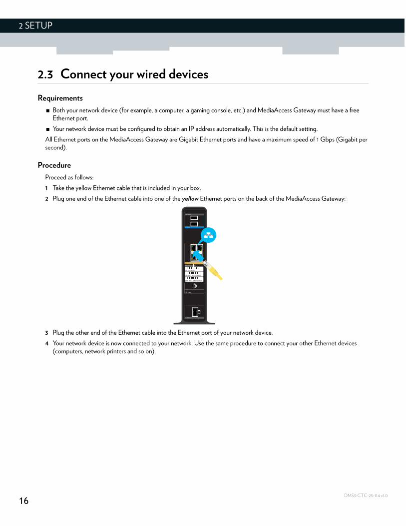
1 Take the yellow Ethernet cable that is included in your box.
2 Plug one end of the Ethernet cable into one of the yellow Ethernet ports on the back of the MediaAccess Gateway:
3 Plug the other end of the Ethernet cable into the Ethernet port of your network device.
4 Your network device is now connected to your network. Use the same procedure to connect your other Ethernet devices (computers, network printers and so on).
17
2 SETUP
DMS3-CTC-25-114 v1.0
2.4 Connect your wireless devices
Introduction
The MediaAccess Gateway has two access points that allows you to connect wireless devices to your home network:
The 5 GHz (3x3) IEEE 802.11ac access point offers superior transfer rates, is less sensitive to interference and allows you to connect IEEE802.11a/n/ac wireless clients.
The 2.4 GHz (3x3) IEEE 802.11n access point allows you to connect IEEE802.11b/g/n wireless clients. Use this access point for wireless clients that don’t support 5 GHz.
Procedure
To connect your device via:
Via WPS, proceed with “2.4.1 How to connect your wireless client via WPS” on page 18.
By manually entering the settings, proceed with “2.4.2 How to manually connect your wireless client” on page 20.
If you want to connect your wireless client to the 5 GHz access point, make sure that your wireless client supports 5 GHz connections.
18
2 SETUP
DMS3-CTC-25-114 v1.0
2.4.1 How to connect your wireless client via WPS
WPS
Wi-Fi Protected Setup (WPS) allows you to add new wireless clients to your local network in a swift and easy way, without the need to enter any of your wireless settings (network name, wireless network key, encryption type).
Both the 2.4 GHz as the 5 GHz access point of your MediaAccess Gateway support WPS.
Requirements
Your wireless client must support WPS. Check the documentation of your wireless client for this.
Your MediaAccess Gateway must use WPA2-PSK (AES) encryption (default encryption) or WPAWPA2-PSK (TKIP/AES) encryption. WPS with WEP encryption is not possible.
WPS methods
The following WPS methods are supported by your MediaAccess Gateway:
Push Button Configuration (PBC):You have to put both the wireless client and the MediaAccess Gateway in registration mode by pushing a hardware or software button.
PIN code entry on the wireless client:You have to enter the MediaAccess Gateway’s WPS PIN code on the wireless client. For more information, see “Adding a wireless client using WPS PIN entry on the wireless client” on page 34.
PIN code entry on the MediaAccess Gateway:You have to enter the wireless client’s WPS PIN code on the Admin Tool. For more information, see “Adding a wireless client using WPS PIN entry on the MediaAccess Gateway” on page 35.
Procedure for PBC
Proceed as follows:
1 Start WPS on your wireless client.
Windows 8, Windows 7 and Windows Vista Service Pack 1 have native WPS support.
19
2 SETUP
DMS3-CTC-25-114 v1.0
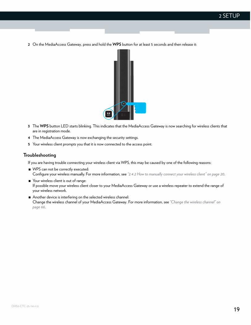
2 On the MediaAccess Gateway, press and hold the WPS button for at least 5 seconds and then release it:
3 The WPS button LED starts blinking. This indicates that the MediaAccess Gateway is now searching for wireless clients that are in registration mode.
4 The MediaAccess Gateway is now exchanging the security settings.
5 Your wireless client prompts you that it is now connected to the access point.
Troubleshooting
If you are having trouble connecting your wireless client via WPS, this may be caused by one of the following reasons:
WPS can not be correctly executed:Configure your wireless manually. For more information, see “2.4.2 How to manually connect your wireless client” on page 20.
Your wireless client is out of range:If possible move your wireless client closer to your MediaAccess Gateway or use a wireless repeater to extend the range of your wireless network.
Another device is interfering on the selected wireless channel:Change the wireless channel of your MediaAccess Gateway. For more information, see “Change the wireless channel” on page 66.
20
2 SETUP
DMS3-CTC-25-114 v1.0
2.4.2 How to manually connect your wireless client
Requirements
Your network device must be equipped with a Wi-Fi Certified wireless client.
Your network device must be configured to obtain an IP address automatically. This is the default setting.
Procedure
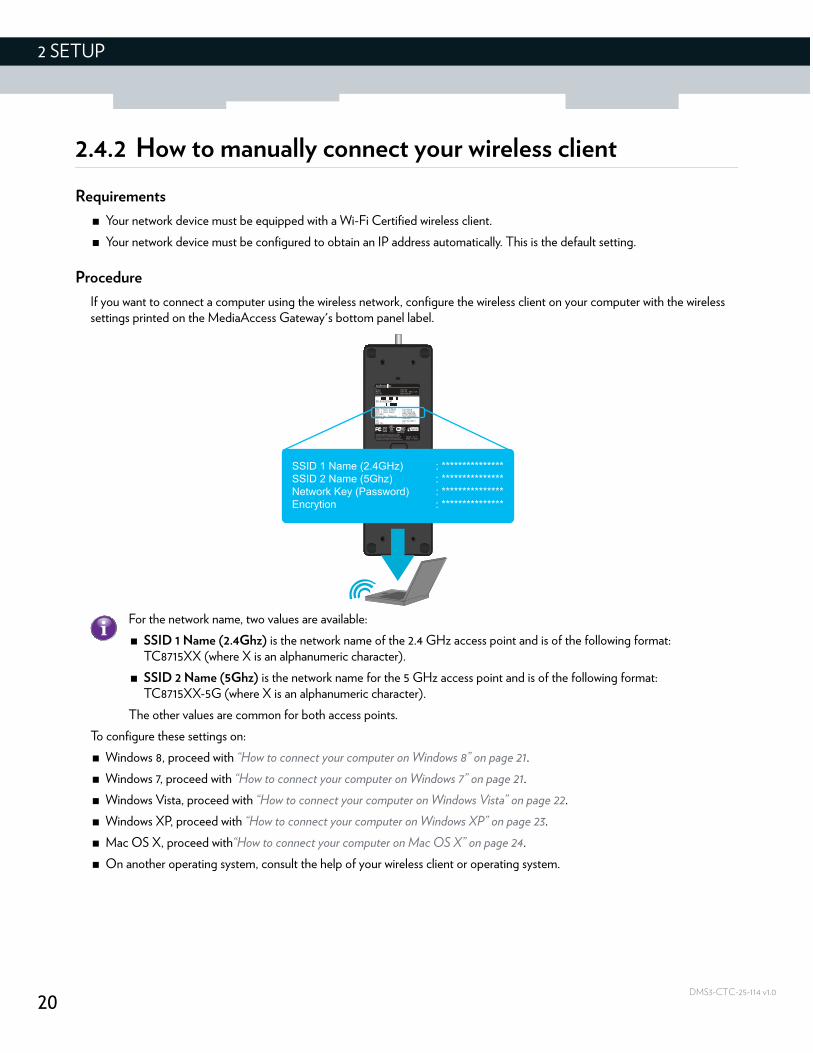
If you want to connect a computer using the wireless network, configure the wireless client on your computer with the wireless settings printed on the MediaAccess Gateway's bottom panel label.
To configure these settings on:
Windows 8, proceed with “How to connect your computer on Windows 8” on page 21.
Windows 7, proceed with “How to connect your computer on Windows 7” on page 21.
Windows Vista, proceed with “How to connect your computer on Windows Vista” on page 22.
Windows XP, proceed with “How to connect your computer on Windows XP” on page 23.
Mac OS X, proceed with“How to connect your computer on Mac OS X” on page 24.
On another operating system, consult the help of your wireless client or operating system.
For the network name, two values are available:
SSID 1 Name (2.4Ghz) is the network name of the 2.4 GHz access point and is of the following format: TC8715XX (where X is an alphanumeric character).
SSID 2 Name (5Ghz) is the network name for the 5 GHz access point and is of the following format: TC8715XX-5G (where X is an alphanumeric character).
The other values are common for both access points.
SSID 1 Name (2.4GHz) : ***************SSID 2 Name (5Ghz) : ***************Network Key (Password) : ***************Encrytion : ***************
21
2 SETUP
DMS3-CTC-25-114 v1.0
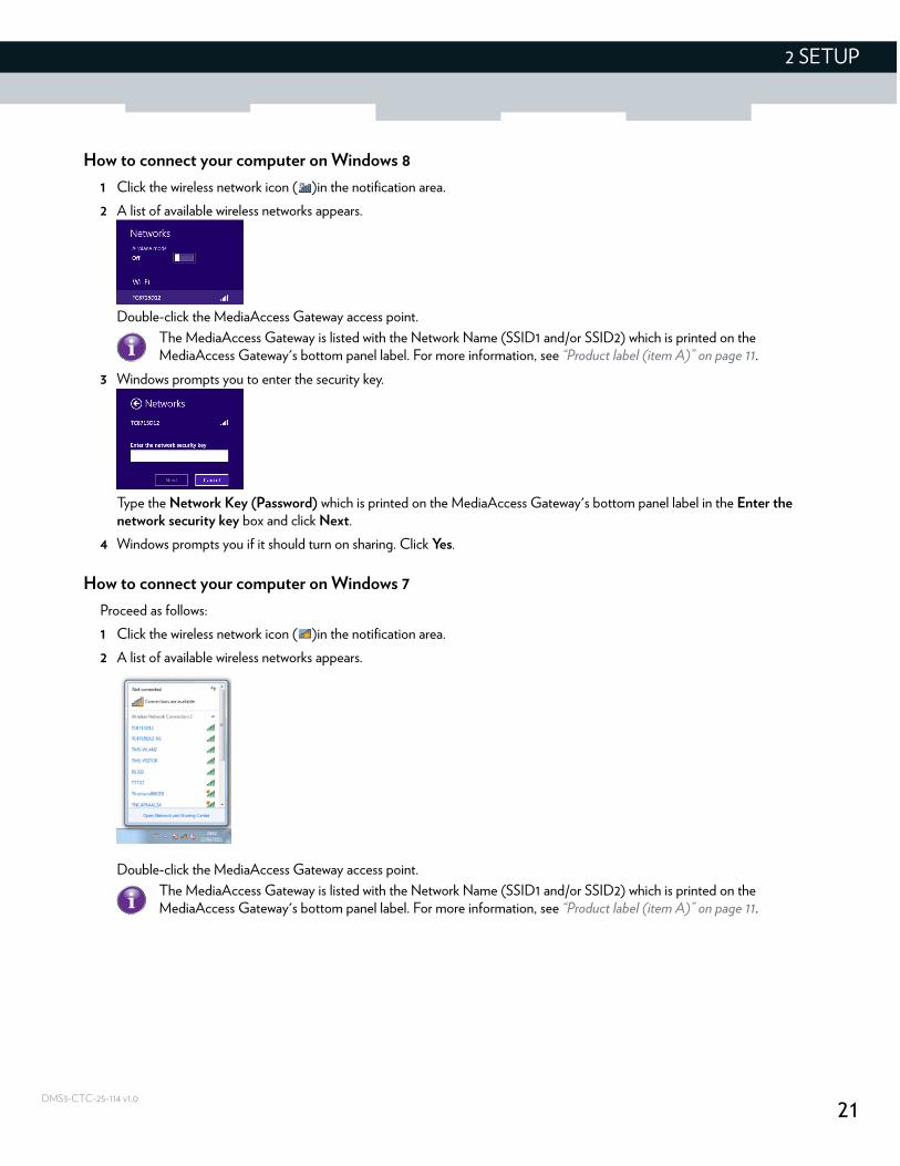
How to connect your computer on Windows 8
1 Click the wireless network icon ( )in the notification area.
2 A list of available wireless networks appears.
Double-click the MediaAccess Gateway access point.
3 Windows prompts you to enter the security key.
Type the Network Key (Password) which is printed on the MediaAccess Gateway's bottom panel label in the Enter the network security key box and click Next.
4 Windows prompts you if it should turn on sharing. Click Yes.
How to connect your computer on Windows 7
Proceed as follows:
1 Click the wireless network icon ( )in the notification area.
2 A list of available wireless networks appears.
Double-click the MediaAccess Gateway access point.
The MediaAccess Gateway is listed with the Network Name (SSID1 and/or SSID2) which is printed on the MediaAccess Gateway's bottom panel label. For more information, see “Product label (item A)” on page 11.
The MediaAccess Gateway is listed with the Network Name (SSID1 and/or SSID2) which is printed on the MediaAccess Gateway's bottom panel label. For more information, see “Product label (item A)” on page 11.
22
2 SETUP
DMS3-CTC-25-114 v1.0
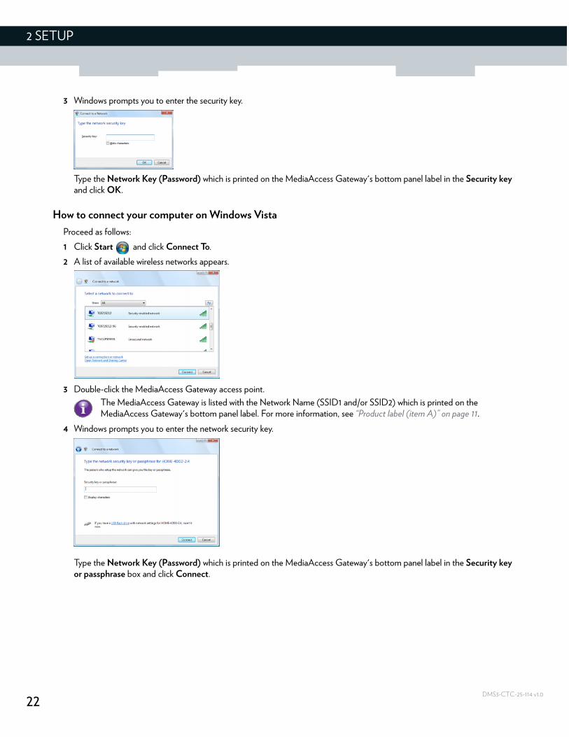
3 Windows prompts you to enter the security key.
Type the Network Key (Password) which is printed on the MediaAccess Gateway's bottom panel label in the Security key and click OK.
How to connect your computer on Windows Vista
Proceed as follows:
1 Click Start and click Connect To.
2 A list of available wireless networks appears.
3 Double-click the MediaAccess Gateway access point.
4 Windows prompts you to enter the network security key.
Type the Network Key (Password) which is printed on the MediaAccess Gateway's bottom panel label in the Security key or passphrase box and click Connect.
The MediaAccess Gateway is listed with the Network Name (SSID1 and/or SSID2) which is printed on the MediaAccess Gateway's bottom panel label. For more information, see “Product label (item A)” on page 11.
23
2 SETUP
DMS3-CTC-25-114 v1.0
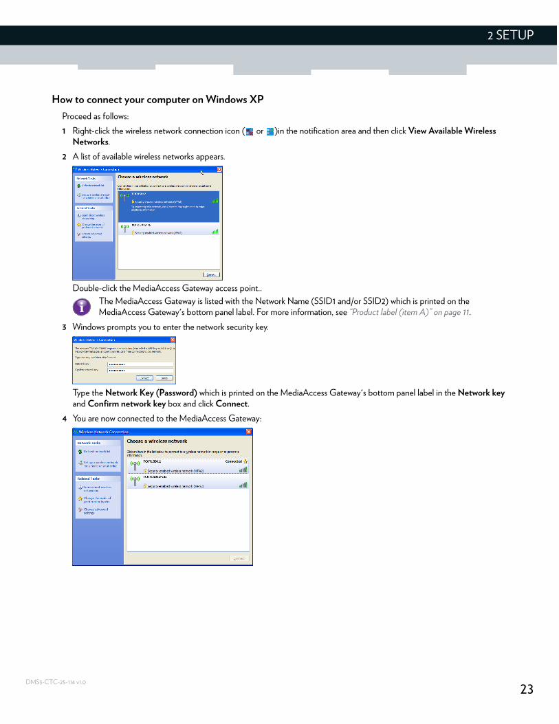
How to connect your computer on Windows XP
Proceed as follows:
1 Right-click the wireless network connection icon ( or )in the notification area and then click View Available Wireless Networks.
2 A list of available wireless networks appears.
Double-click the MediaAccess Gateway access point..
3 Windows prompts you to enter the network security key.
Type the Network Key (Password) which is printed on the MediaAccess Gateway's bottom panel label in the Network key and Confirm network key box and click Connect.
4 You are now connected to the MediaAccess Gateway:
The MediaAccess Gateway is listed with the Network Name (SSID1 and/or SSID2) which is printed on the MediaAccess Gateway's bottom panel label. For more information, see “Product label (item A)” on page 11.
24
2 SETUP
DMS3-CTC-25-114 v1.0
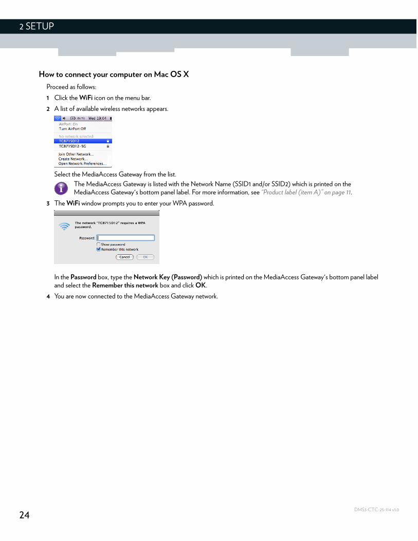
How to connect your computer on Mac OS X
Proceed as follows:
1 Click the WiFi icon on the menu bar.
2 A list of available wireless networks appears.
Select the MediaAccess Gateway from the list.
3 The WiFi window prompts you to enter your WPA password.
In the Password box, type the Network Key (Password) which is printed on the MediaAccess Gateway's bottom panel label and select the Remember this network box and click OK.
4 You are now connected to the MediaAccess Gateway network.
The MediaAccess Gateway is listed with the Network Name (SSID1 and/or SSID2) which is printed on the MediaAccess Gateway's bottom panel label. For more information, see “Product label (item A)” on page 11.
25
3 ADMIN TOOL
DMS3-CTC-25-114 v1.0
3 Admin Tool
Introduction
The Admin Tool allows you to configure the settings of your MediaAccess Gateway via your web browser.
Requirements
JavaScript must be enabled on your browser (this is the default setting). For more information, consult the help of your web browser.
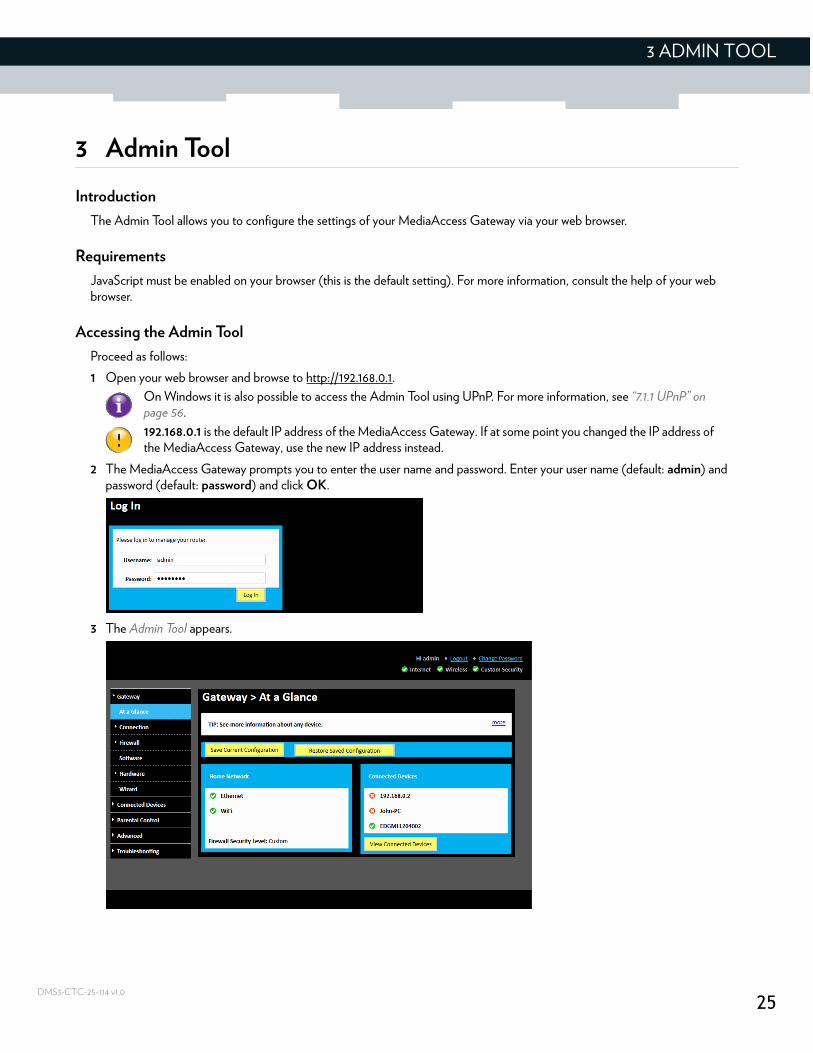
Accessing the Admin Tool
Proceed as follows:
1 Open your web browser and browse to http://192.168.0.1.
2 The MediaAccess Gateway prompts you to enter the user name and password. Enter your user name (default: admin) and password (default: password) and click OK.
3 The Admin Tool appears.
On Windows it is also possible to access the Admin Tool using UPnP. For more information, see “7.1.1 UPnP” on page 56.
192.168.0.1 is the default IP address of the MediaAccess Gateway. If at some point you changed the IP address of the MediaAccess Gateway, use the new IP address instead.
26
3 ADMIN TOOL
DMS3-CTC-25-114 v1.0
3.1 Components
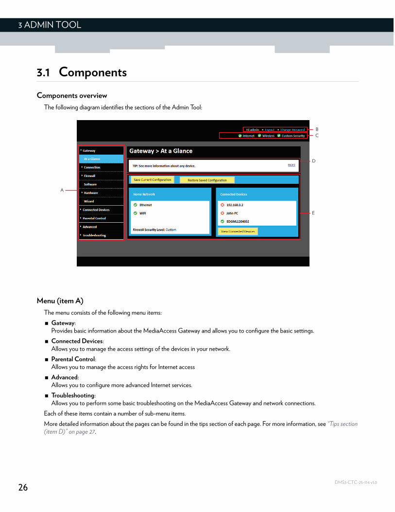
Components overview
The following diagram identifies the sections of the Admin Tool:
Menu (item A)
The menu consists of the following menu items:
Gateway:Provides basic information about the MediaAccess Gateway and allows you to configure the basic settings.
Connected Devices:Allows you to manage the access settings of the devices in your network.
Parental Control:Allows you to manage the access rights for Internet access
Advanced:Allows you to configure more advanced Internet services.
Troubleshooting:Allows you to perform some basic troubleshooting on the MediaAccess Gateway and network connections.
Each of these items contain a number of sub-menu items.
More detailed information about the pages can be found in the tips section of each page. For more information, see “Tips section (item D)” on page 27.
D
A
E
C
B
27
3 ADMIN TOOL
DMS3-CTC-25-114 v1.0
Login section (item B)
In the login section you can see the following details:
User Name
Option to logout
Option to change the Admin Tool password
Status section (item C)
The diagnostics section provides a quick overview of:
The status of the Internet interface
The status of the wireless interface
The selected firewall level
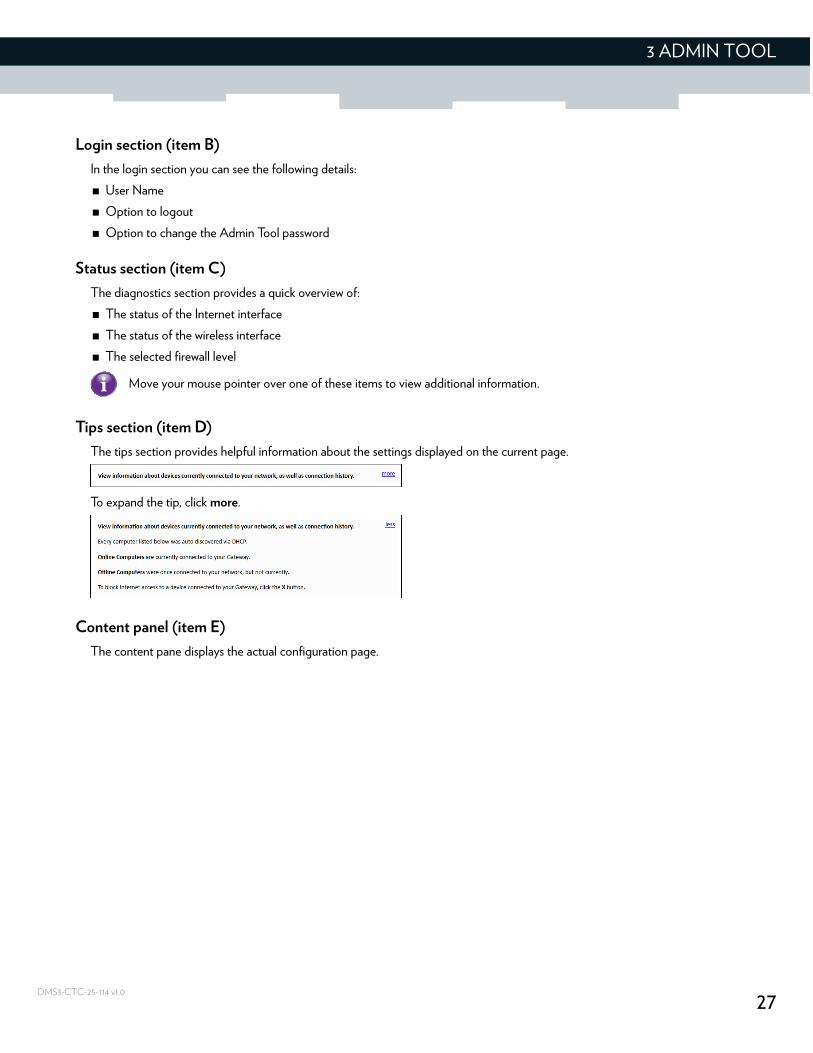
Tips section (item D)
The tips section provides helpful information about the settings displayed on the current page.
To expand the tip, click more.
Content panel (item E)
The content pane displays the actual configuration page.
Move your mouse pointer over one of these items to view additional information.
28
3 ADMIN TOOL
DMS3-CTC-25-114 v1.0
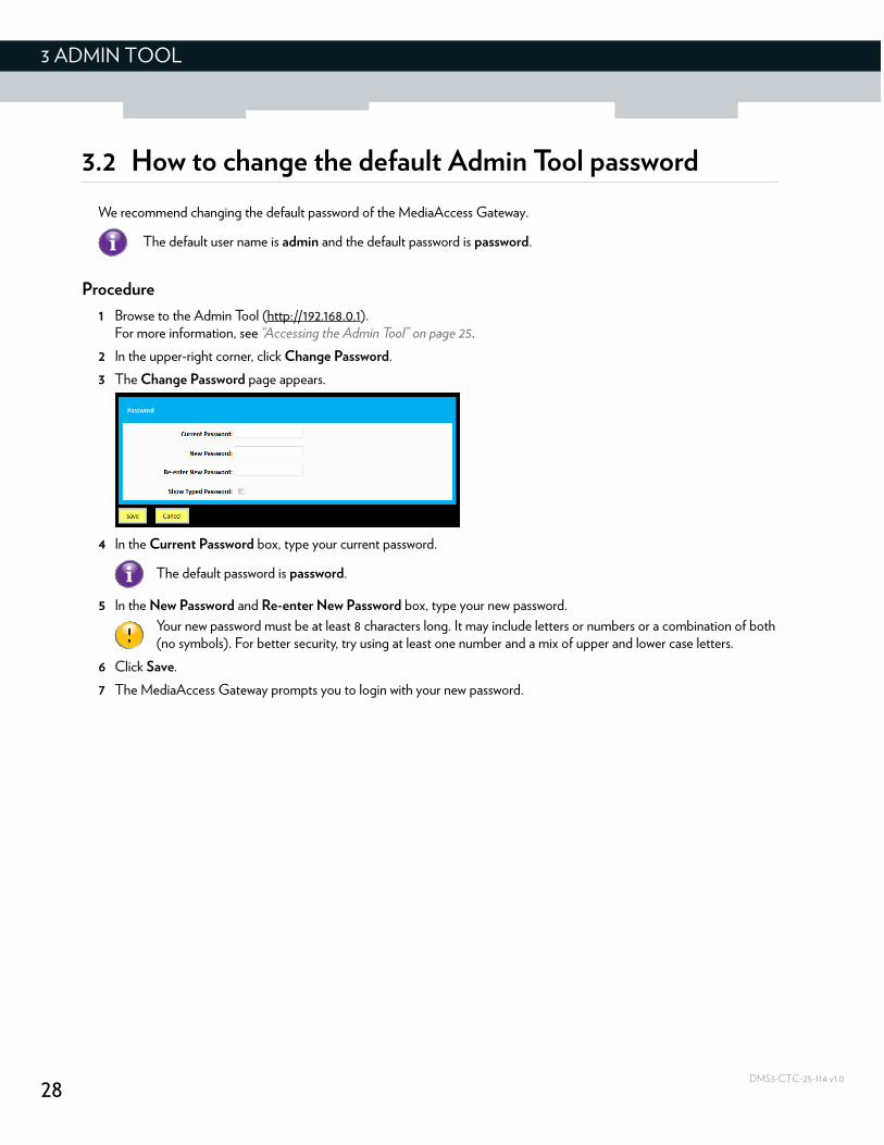
3.2 How to change the default Admin Tool password
We recommend changing the default password of the MediaAccess Gateway.
Procedure
1 Browse to the Admin Tool (http://192.168.0.1).For more information, see “Accessing the Admin Tool” on page 25.
2 In the upper-right corner, click Change Password.
3 The Change Password page appears.
4 In the Current Password box, type your current password.
5 In the New Password and Re-enter New Password box, type your new password.
6 Click Save.
7 The MediaAccess Gateway prompts you to login with your new password.
The default user name is admin and the default password is password.
The default password is password.
Your new password must be at least 8 characters long. It may include letters or numbers or a combination of both (no symbols). For better security, try using at least one number and a mix of upper and lower case letters.
29
3 ADMIN TOOL
DMS3-CTC-25-114 v1.0
3.3 How to backup or restore a configuration
Introduction
Once you have configured your MediaAccess Gateway to your needs, it is recommended to backup your configuration for later use. This way you can always return to your working configuration in case of problems.
Backing up your configuration
Proceed as follows:
1 Browse to the Admin Tool (http://192.168.0.1).For more information, see “Accessing the Admin Tool” on page 25.
2 The At a Glance page appears. Click Save Current Configuration.
3 Your browser prompts you to save or open the backup file. Save your file to a location of your choice.
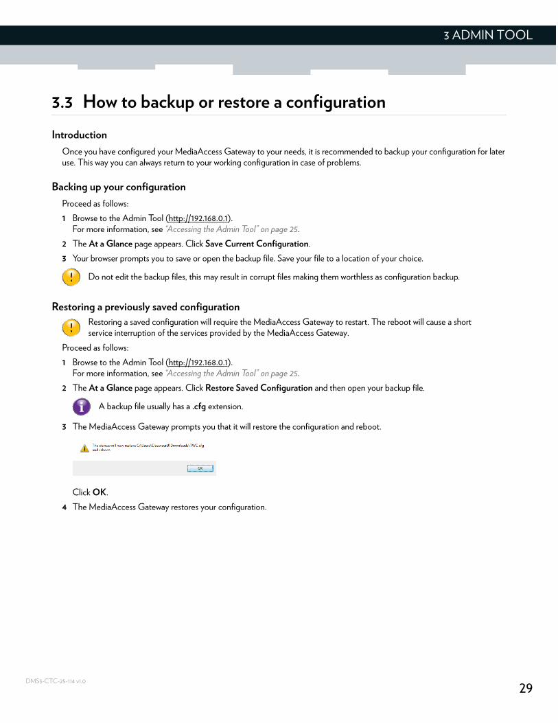
Restoring a previously saved configuration
Proceed as follows:
1 Browse to the Admin Tool (http://192.168.0.1).For more information, see “Accessing the Admin Tool” on page 25.
2 The At a Glance page appears. Click Restore Saved Configuration and then open your backup file.
3 The MediaAccess Gateway prompts you that it will restore the configuration and reboot.
Click OK.
4 The MediaAccess Gateway restores your configuration.
Do not edit the backup files, this may result in corrupt files making them worthless as configuration backup.
Restoring a saved configuration will require the MediaAccess Gateway to restart. The reboot will cause a short service interruption of the services provided by the MediaAccess Gateway.
A backup file usually has a .cfg extension.

30
3 ADMIN TOOL
DMS3-CTC-25-114 v1.0
31
4 THE MEDIAACCESS GATEWAY WIRELESS ACCESS POINT
DMS3-CTC-25-114 v1.0
4 The MediaAccess Gateway wireless access point
Introduction
This section will help you set up your wireless network.
What you need to set up a wireless network
To set up a wireless network, you need the following components:
A Wireless access point (already integrated into your MediaAccess Gateway)
A Wireless client the device that you want to connect (for example, a computer, smartphone, network printer,...)
Wireless access point
The wireless access point is the heart of your wireless network. The wireless access point:
Connects different wireless clients.
Secures the data sent over wireless connection.
The MediaAccess Gateway has two access points:
A 5 GHz (3x3) IEEE 802.11ac access point that offers superior transfer rates, is less sensitive to interference and allows you to connect IEEE802.11a/n/ac wireless clients.
A 2.4 GHz (3x3) IEEE 802.11n access point that allows you to connect IEEE802.11b/g/n wireless clients. Use this access point for wireless clients that don’t support 5 GHz.
Wireless client
The wireless client allows you to connect a wireless client to a wireless access point. Both built-in and external (for example via USB) wireless clients are available.
Check the documentation of your computer if you are not sure if your computer is equipped with a wireless client.
Configuring your wireless clients
For more information on how to establish a wireless connection to the MediaAccess Gateway, see:
“2.4.1 How to connect your wireless client via WPS” on page 18
“2.4.2 How to manually connect your wireless client” on page 20
If you want to connect your wireless client to the 5 GHz access point, make sure that your wireless client supports 5 GHz connections.
Devices like tablets, smart TVs and smartphones usually have a built-in wireless client. Check the documentation of your device for more information.
32
4 THE MEDIAACCESS GATEWAY WIRELESS ACCESS POINT
DMS3-CTC-25-114 v1.0
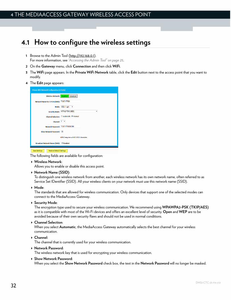
4.1 How to configure the wireless settings
1 Browse to the Admin Tool (http://192.168.0.1).For more information, see “Accessing the Admin Tool” on page 25.
2 On the Gateway menu, click Connection and then click WiFi.
3 The WiFi page appears. In the Private WiFi Network table, click the Edit button next to the access point that you want to modify.
4 The Edit page appears:
The following fields are available for configuration:
Wireless Network:Allows you to enable or disable this access point.
Network Name (SSID):To distinguish one wireless network from another, each wireless network has its own network name, often referred to as Service Set IDentifier (SSID). All your wireless clients on your network must use this network name (SSID).
Mode:The standards that are allowed for wireless communication. Only devices that support one of the selected modes can connect to the MediaAccess Gateway.
Security Mode:The encryption type used to secure your wireless communication. We recommend using WPAWPA2-PSK (TKIP/AES) as it is compatible with most of the Wi-Fi devices and offers an excellent level of security. Open and WEP are to be avoided because of their own security flaws and should not be used in normal conditions.
Channel Selection:When you select Automatic, the MediaAccess Gateway automatically selects the best channel for your wireless communication.
Channel:The channel that is currently used for your wireless communication.
Network Password:The wireless network key that is used for encrypting your wireless communication.
Show Network Password:When you select the Show Network Password check box, the text in the Network Password will no longer be masked.
33
4 THE MEDIAACCESS GATEWAY WIRELESS ACCESS POINT
DMS3-CTC-25-114 v1.0
Broadcast Network Name (SSID):By default, the MediaAccess Gateway broadcasts its network name. Wireless clients can then detect the presence of your network and inform the users that this network is available.
5 Click Save Settings.
Enabling SSID broadcast does not mean that everyone can connect to your network. They still need the correct wireless network key (password) to connect to the MediaAccess Gateway network. It only informs them that your network is present.
SSID broadcasting is required for WPS.
34
4 THE MEDIAACCESS GATEWAY WIRELESS ACCESS POINT
DMS3-CTC-25-114 v1.0
4.2 How to start a WPS session via the Admin Tool
Adding a wireless client using WPS PBC
1 Make sure that the WPS button of your wireless client is accessible. This button can be a hardware button or a software button.
2 Browse to the Admin Tool (http://192.168.0.1).For more information, see “Accessing the Admin Tool” on page 25.
3 On the Gateway menu, click Connection and then click WiFi.
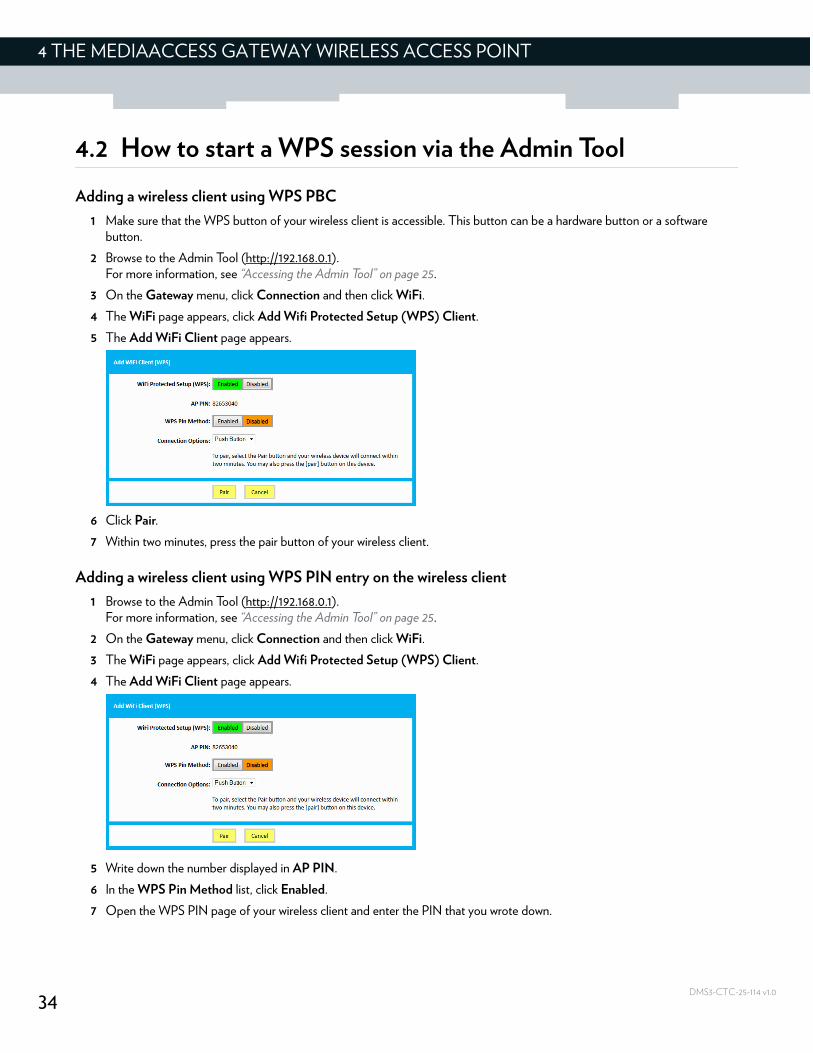
4 The WiFi page appears, click Add Wifi Protected Setup (WPS) Client.
5 The Add WiFi Client page appears.
6 Click Pair.
7 Within two minutes, press the pair button of your wireless client.
Adding a wireless client using WPS PIN entry on the wireless client
1 Browse to the Admin Tool (http://192.168.0.1).For more information, see “Accessing the Admin Tool” on page 25.
2 On the Gateway menu, click Connection and then click WiFi.
3 The WiFi page appears, click Add Wifi Protected Setup (WPS) Client.
4 The Add WiFi Client page appears.
5 Write down the number displayed in AP PIN.
6 In the WPS Pin Method list, click Enabled.
7 Open the WPS PIN page of your wireless client and enter the PIN that you wrote down.
35
4 THE MEDIAACCESS GATEWAY WIRELESS ACCESS POINT
DMS3-CTC-25-114 v1.0
Adding a wireless client using WPS PIN entry on the MediaAccess Gateway
1 Locate and write down the WPS PIN of your wireless client. For more information, consult the documentation of your wireless client.
2 Browse to the Admin Tool (http://192.168.0.1).For more information, see “Accessing the Admin Tool” on page 25.
3 On the Gateway menu, click Connection and then click WiFi.
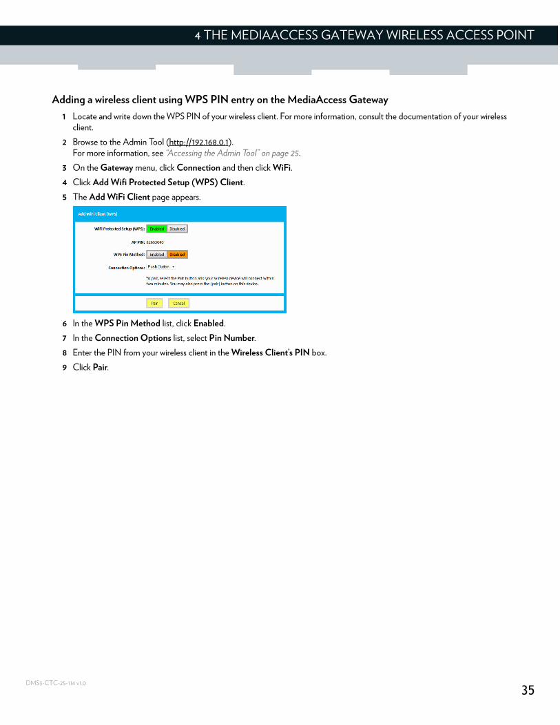
4 Click Add Wifi Protected Setup (WPS) Client.
5 The Add WiFi Client page appears.
6 In the WPS Pin Method list, click Enabled.
7 In the Connection Options list, select Pin Number.
8 Enter the PIN from your wireless client in the Wireless Client’s PIN box.
9 Click Pair.
36
4 THE MEDIAACCESS GATEWAY WIRELESS ACCESS POINT
DMS3-CTC-25-114 v1.0
4.3 Prevent devices from accessing your wireless network
MAC address
A MAC (Media Access Control) address is a unique hexadecimal code that identifies a device on a network. Each network-enabled device has at least one unique MAC address.
For example, if your computer is equipped with an Ethernet and a wireless network adaptor, each of these interfaces will have its own MAC address.
MAC filtering
When using MAC filtering, you allow or deny devices to access your network based on their MAC address.
How to set up MAC filtering
1 Browse to the Admin Tool (http://192.168.0.1).For more information, see “Accessing the Admin Tool” on page 25.
2 On the Gateway menu, click Connection and then click WiFi.
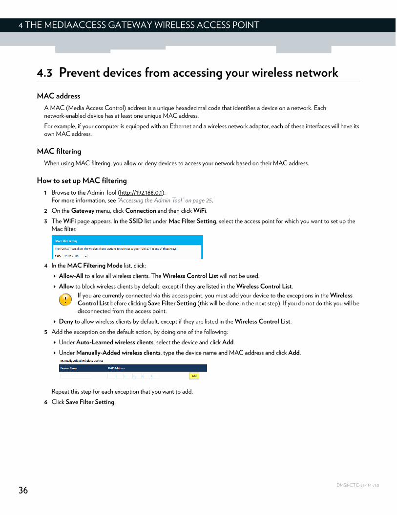
3 The WiFi page appears. In the SSID list under Mac Filter Setting, select the access point for which you want to set up the Mac filter.
4 In the MAC Filtering Mode list, click:
Allow-All to allow all wireless clients. The Wireless Control List will not be used.
Allow to block wireless clients by default, except if they are listed in the Wireless Control List.
Deny to allow wireless clients by default, except if they are listed in the Wireless Control List.
5 Add the exception on the default action, by doing one of the following:
Under Auto-Learned wireless clients, select the device and click Add.
Under Manually-Added wireless clients, type the device name and MAC address and click Add.
Repeat this step for each exception that you want to add.
6 Click Save Filter Setting.
If you are currently connected via this access point, you must add your device to the exceptions in the Wireless Control List before clicking Save Filter Setting (this will be done in the next step). If you do not do this you will be disconnected from the access point.
37
5 SHARING CONTENT
DMS3-CTC-25-114 v1.0
5 Sharing content
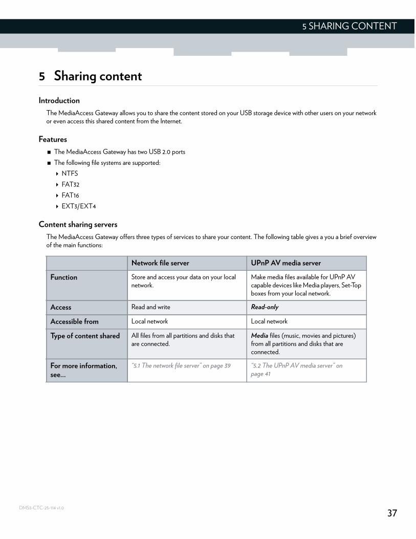
Introduction
The MediaAccess Gateway allows you to share the content stored on your USB storage device with other users on your network or even access this shared content from the Internet.
Features
The MediaAccess Gateway has two USB 2.0 ports
The following file systems are supported:
NTFS
FAT32
FAT16
EXT3/EXT4
Content sharing servers
The MediaAccess Gateway offers three types of services to share your content. The following table gives a you a brief overview of the main functions:
Network file server UPnP AV media server
Function Store and access your data on your local network.
Make media files available for UPnP AV capable devices like Media players, Set-Top boxes from your local network.
Access Read and write Read-only
Accessible from Local network Local network
Type of content shared All files from all partitions and disks that are connected.
Media files (music, movies and pictures) from all partitions and disks that are connected.
For more information, see...
“5.1 The network file server” on page 39 “5.2 The UPnP AV media server” on page 41
38
5 SHARING CONTENT
DMS3-CTC-25-114 v1.0
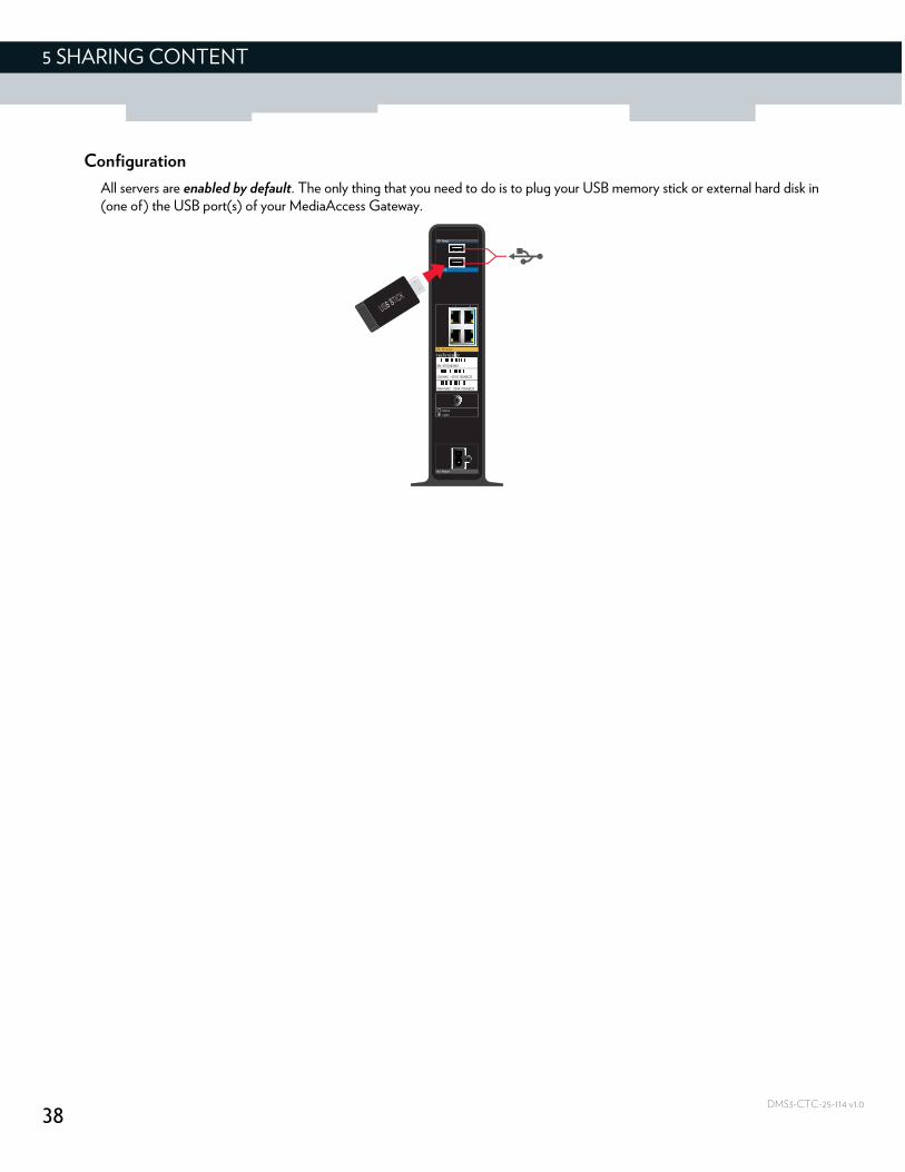
Configuration
All servers are enabled by default. The only thing that you need to do is to plug your USB memory stick or external hard disk in (one of) the USB port(s) of your MediaAccess Gateway.
39
5 SHARING CONTENT
DMS3-CTC-25-114 v1.0
5.1 The network file server
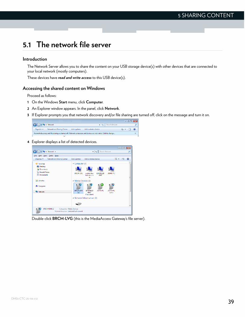
Introduction
The Network Server allows you to share the content on your USB storage device(s) with other devices that are connected to your local network (mostly computers).
These devices have read and write access to this USB device(s).
Accessing the shared content on Windows
Proceed as follows:
1 On the Windows Start menu, click Computer.
2 An Explorer window appears. In the panel, click Network.
3 If Explorer prompts you that network discovery and/or file sharing are turned off, click on the message and turn it on.
4 Explorer displays a list of detected devices.
Double-click BRCM-LVG (this is the MediaAccess Gateway’s file server).
40
5 SHARING CONTENT
DMS3-CTC-25-114 v1.0
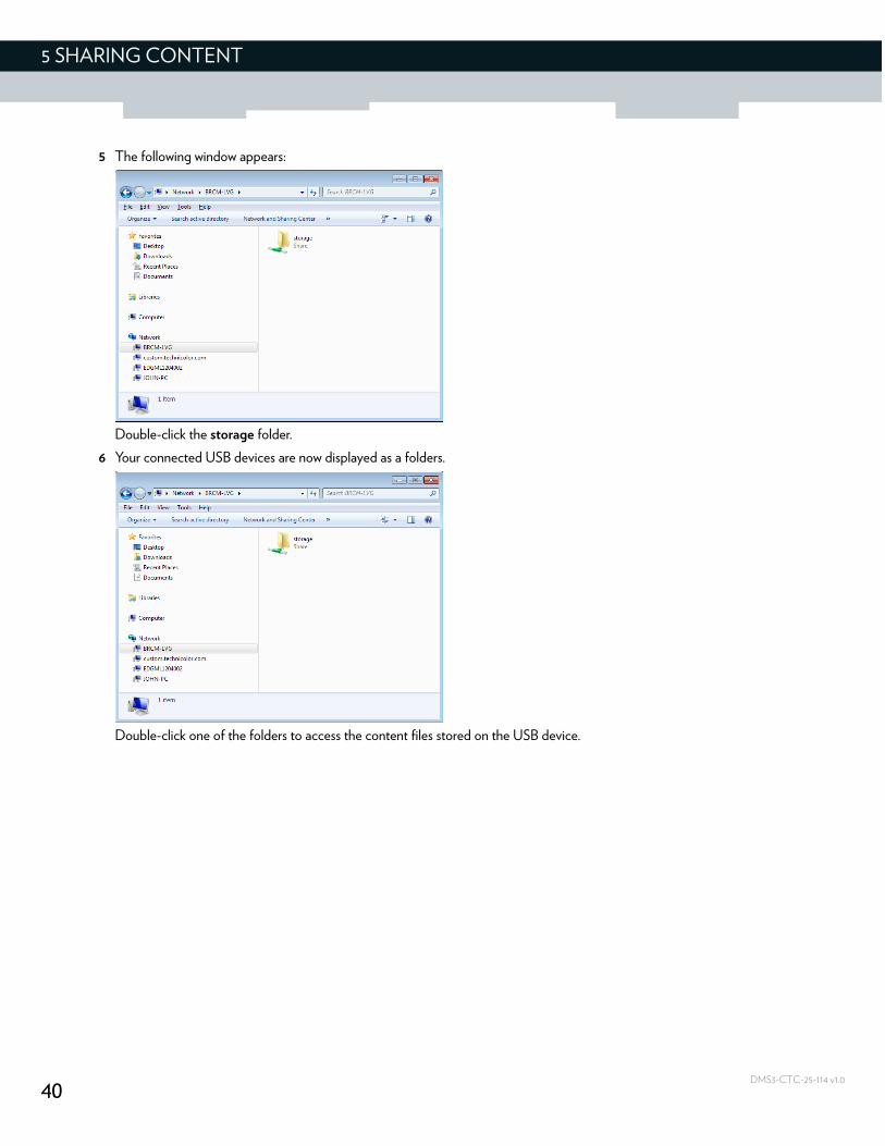
5 The following window appears:
Double-click the storage folder.
6 Your connected USB devices are now displayed as a folders.
Double-click one of the folders to access the content files stored on the USB device.
41
5 SHARING CONTENT
DMS3-CTC-25-114 v1.0
5.2 The UPnP AV media server
Introduction
Your MediaAccess Gateway has a built-in DLNA Certified UPnP AV media server. This section describes how to use and configure this media server.
UPnP AV
UPnP AV (Universal Plug and Play Audio/Video) is a protocol especially designed to share media files on your local network.
DLNA certified
The Digital Living Network Alliance (DLNA) is an organization that imposes requirements to ensure the interoperability of your media devices and standardize the communication between them.
Buying a DLNA certified device like the MediaAccess Gateway guarantees that it will seamlessly integrate with your other DLNA certified devices.
To allow you to access your media in a quick and easy way, the MediaAccess Gateway scans your storage device for meta data information (for example, title, artist, album) and stores it in a database. When you are looking for a file, the MediaAccess Gateway can simply query the database instead of having to go through all the files.
UPnP AV network components
A UPnP AV network consists of the following components:
The UPnP AV server is directly connected to your media files and makes them available on the network. In your network the MediaAccess Gateway will fulfil this role.
The UPnP AV client is a software application or hardware device that allows you to play or view the media files provided by your UPnP AV media server.
Accessing your media files via UPnP AV
The UPnP AV media server lists all audio, video and picture files located on the connected USB storage device. All UPnP AV renderers (for example, a DLNA Certified set-top box) that are connected to your network are able to view this list and play or view items from this list.
On your UPnP AV client, the MediaAccess Gateway’s UPnP AV media server will be listed as BRCM-DMS.
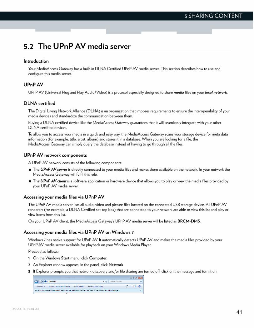
Accessing your media files via UPnP AV on Windows 7
Windows 7 has native support for UPnP AV. It automatically detects UPnP AV and makes the media files provided by your UPnP AV media server available for playback on your Windows Media Player.
Proceed as follows:
1 On the Windows Start menu, click Computer.
2 An Explorer window appears. In the panel, click Network.
3 If Explorer prompts you that network discovery and/or file sharing are turned off, click on the message and turn it on.
42
5 SHARING CONTENT
DMS3-CTC-25-114 v1.0
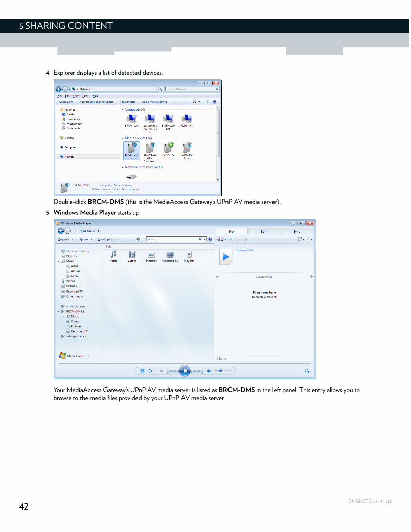
4 Explorer displays a list of detected devices.
Double-click BRCM-DMS (this is the MediaAccess Gateway’s UPnP AV media server).
5 Windows Media Player starts up.
Your MediaAccess Gateway’s UPnP AV media server is listed as BRCM-DMS in the left panel. This entry allows you to browse to the media files provided by your UPnP AV media server.
43
6 INTERNET SECURITY
DMS3-CTC-25-114 v1.0
6 Internet security
Overview
The MediaAccess Gateway offers various options to secure your Internet connection:
Topic Page
6.1 Parental control 44
6.1.1 Manage sites 45
6.1.2 Manage services 47
6.1.3 Manage devices 49
6.1.4 View parental control reports 51
6.2 Firewall 52
44
6 INTERNET SECURITY
DMS3-CTC-25-114 v1.0
6.1 Parental control
Introduction
The parental control function:
Prevents access to specific website based on the URL or keywords.For more information, see “6.1.1 Manage sites” on page 45.
Prevents access to specific application or services (for example, FTP).For more information, see “6.1.2 Manage services” on page 47.
Prevents devices from accessing your network.For more information, see “6.1.3 Manage devices” on page 49.
45
6 INTERNET SECURITY
DMS3-CTC-25-114 v1.0
6.1.1 Manage sites
Introduction
The Managed Sites page allows you to:
Block specific websites (always or for a specific time frame)
Block keywords (always or for a specific time frame)
Mark devices as trustedWhen a device is marked as trusted, all Managed Sites rules will be ignored.
How to access the Managed Sites page
1 Browse to the Admin Tool (http://192.168.0.1).For more information, see “Accessing the Admin Tool” on page 25.
2 On the left menu, click Parental Control.
3 The Managed Sites page appears.
4 In the Enable Managed Sites list, click Enable.
How to block a specific website
Proceed as follows, from the Managed Sites page:
1 Under Blocked Sites, click + Add.
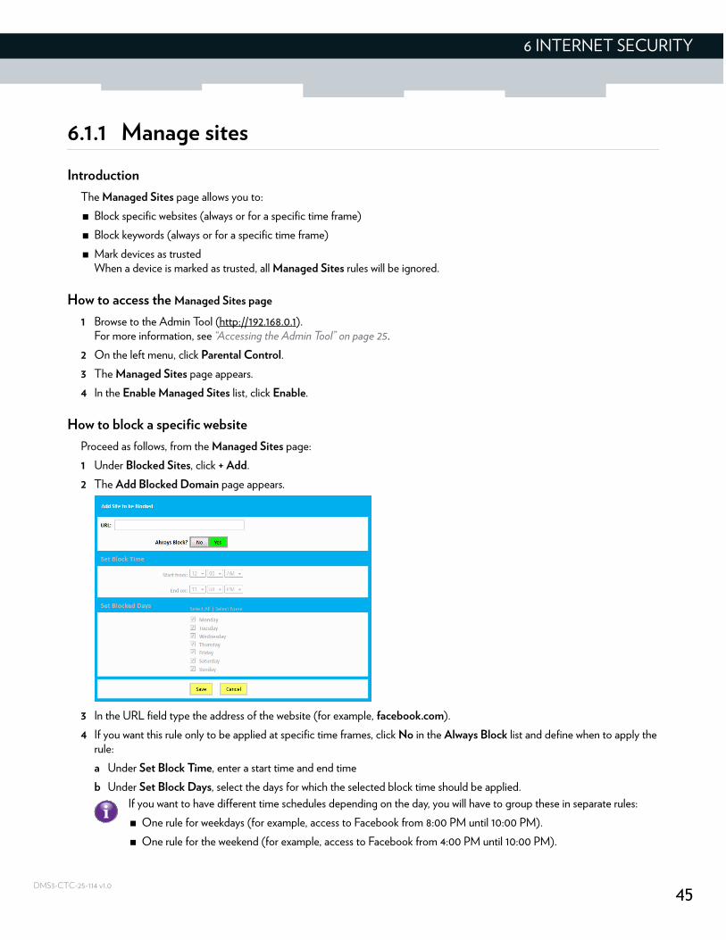
2 The Add Blocked Domain page appears.
3 In the URL field type the address of the website (for example, facebook.com).
4 If you want this rule only to be applied at specific time frames, click No in the Always Block list and define when to apply the rule:
a Under Set Block Time, enter a start time and end time
b Under Set Block Days, select the days for which the selected block time should be applied.
If you want to have different time schedules depending on the day, you will have to group these in separate rules:
One rule for weekdays (for example, access to Facebook from 8:00 PM until 10:00 PM).
One rule for the weekend (for example, access to Facebook from 4:00 PM until 10:00 PM).
46
6 INTERNET SECURITY
DMS3-CTC-25-114 v1.0
5 Click Save.
How to block websites based on keywords
Proceed as follows, from the Managed Sites page:
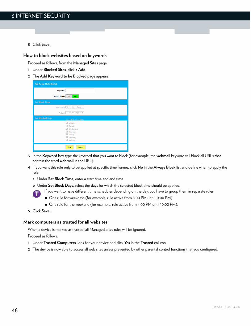
1 Under Blocked Sites, click + Add.
2 The Add Keyword to be Blocked page appears.
3 In the Keyword box type the keyword that you want to block (for example, the webmail keyword will block all URLs that contain the word webmail in the URL).
4 If you want this rule only to be applied at specific time frames, click No in the Always Block list and define when to apply the rule:
a Under Set Block Time, enter a start time and end time
b Under Set Block Days, select the days for which the selected block time should be applied.
5 Click Save.
Mark computers as trusted for all websites
When a device is marked as trusted, all Managed Sites rules will be ignored.
Proceed as follows:
1 Under Trusted Computers, look for your device and click Yes in the Trusted column.
2 The device is now able to access all web sites unless prevented by other parental control functions that you configured.
If you want to have different time schedules depending on the day, you have to group them in separate rules:
One rule for weekdays (for example, rule active from 8:00 PM until 10:00 PM).
One rule for the weekend (for example, rule active from 4:00 PM until 10:00 PM).
47
6 INTERNET SECURITY
DMS3-CTC-25-114 v1.0
6.1.2 Manage services
Introduction
The Managed Services page allows you to:
Create a service-specific rule to block specific Internet services.
Mark computers as trusted. For trusted computer all service rules will be ignored.
How to create a service rule
1 Browse to the Admin Tool (http://192.168.0.1).For more information, see “Accessing the Admin Tool” on page 25.
2 On Parental Control menu, click Managed Services.
3 The Managed Services page appears.
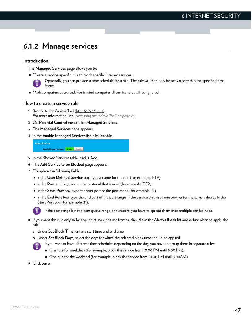
4 In the Enable Managed Services list, click Enable.
5 In the Blocked Services table, click + Add.
6 The Add Service to be Blocked page appears.
7 Complete the following fields:
In the User Defined Service box, type a name for the rule (for example, FTP).
In the Protocol list, click on the protocol that is used (for example, TCP).
In the Start Port box, type the start port of the port range (for example, 21).
In the End Port box, type the end port of the port range. If the service only uses one port, enter the same value as in the Start Port box (for example, 21).
8 If you want this rule only to be applied at specific time frames, click No in the Always Block list and define when to apply the rule:
a Under Set Block Time, enter a start time and end time
b Under Set Block Days, select the days for which the selected block time should be applied.
9 Click Save.
Optionally, you can provide a time schedule for a rule. The rule will then only be activated within the specified time frame.
If the port range is not a contiguous range of numbers, you have to spread them over multiple service rules.
If you want to have different time schedules depending on the day, you have to group them in separate rules:
One rule for weekdays (for example, block the service from 10:00 PM until 8:00 PM).
One rule for the weekend (for example, block the service from 10:00 PM until 8:00AM).

48
6 INTERNET SECURITY
DMS3-CTC-25-114 v1.0
Mark computers as trusted for all services
When a device is marked as trusted, all managed services rules will be ignored.
Proceed as follows:
1 Under Trusted Computers, look for your device and click Yes in the Trusted column.
2 The device is now able to use all web services unless prevented by other parental control functions that you configured.
49
6 INTERNET SECURITY
DMS3-CTC-25-114 v1.0
6.1.3 Manage devices
On the Managed Devices page you can create a device-specific rule to prevent a devices from accessing your network.
Procedure
1 Browse to the Admin Tool (http://192.168.0.1).For more information, see “Accessing the Admin Tool” on page 25.
2 On the Parental Control menu, click Managed Devices.
3 In the Enable Managed Devices list, click Enable.
4 In the Access Type list, click:
Allow All to allow all devices by default. In this case you have to create a rule for each device that you want to block on your network.
Block All to block all devices by default. In this case you have to create a rule for each device that you want to allow on your network.
Adding allowed devices
If you selected Block All in the Access Type list, proceed as follows:
1 In the Allowed Devices table, click +Add Allowed Device.
2 The Add Device to be Allowed page appears.
3 Under Set Allowed Device, select your device from the Learned Device(s) list. If your device is not listed, enter the computer name and MAC address under Custom Device.
4 If you want this rule only to be applied at specific time frames, click No in the Always Allow list and define when to apply the rule:
a Under Set Allow Time, enter a start time and end time
b Under Set Allow Days, select the days for which the selected block time should be applied.
5 Click Save.
Adding blocked devices
If you selected Allow All in the Access Type list, proceed as follows:
1 In the Blocked Devices table, click +Add Blocked Device.
2 The Add Device to be Blocked page appears.
3 Under Set Blocked Device, select your device from the Learned Device(s) list. If your device is not listed, enter the computer name and MAC address under Custom Device.
4 If you want this rule only to be applied at specific time frames, click No in the Always Block list and define when to apply the rule:
a Under Set Block Time, enter a start time and end time.
Optionally, you can provide a time schedule for a rule. The rule will then only be activated within the specified time frame.
If you want to have different time schedules depending on the day, you have to group them in separate rules:
One rule for weekdays (for example, allow the device from 10:00 PM until 8:00 PM).
One rule for the weekend (for example, allow the device from 10:00 PM until 8:00 AM).
50
6 INTERNET SECURITY
DMS3-CTC-25-114 v1.0
b Under Set Block Days, select the days for which the selected block time should be applied.
5 Click Save.
If you want to have different time schedules depending on the day, you have to group them in separate rules:
One rule for weekdays (for example, block the device from 8:00 PM until 10:00 PM).
One rule for the weekend (for example, block the device from 8:00 AM until 10:00 PM).
51
6 INTERNET SECURITY
DMS3-CTC-25-114 v1.0
6.1.4 View parental control reports
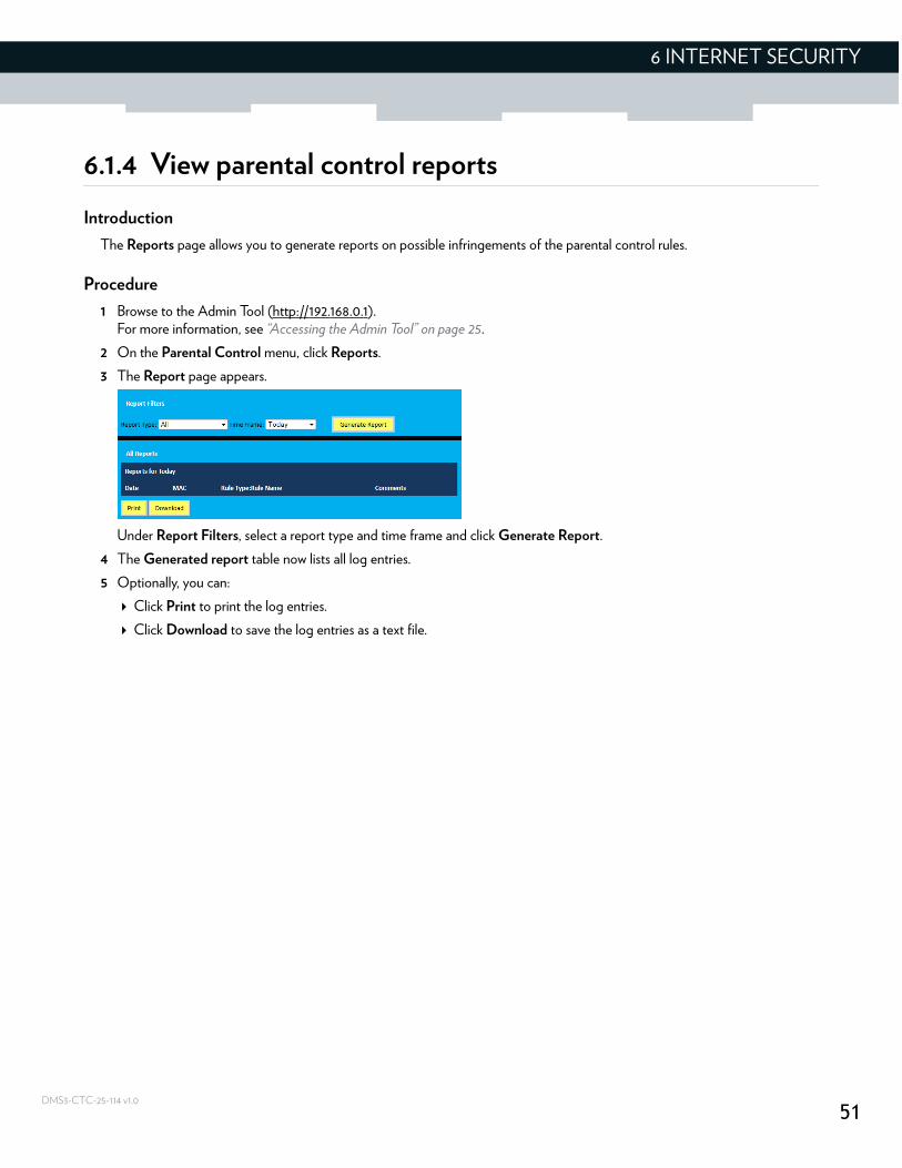
Introduction
The Reports page allows you to generate reports on possible infringements of the parental control rules.
Procedure
1 Browse to the Admin Tool (http://192.168.0.1).For more information, see “Accessing the Admin Tool” on page 25.
2 On the Parental Control menu, click Reports.
3 The Report page appears.
Under Report Filters, select a report type and time frame and click Generate Report.
4 The Generated report table now lists all log entries.
5 Optionally, you can:
Click Print to print the log entries.
Click Download to save the log entries as a text file.
52
6 INTERNET SECURITY
DMS3-CTC-25-114 v1.0
6.2 Firewall
Introduction
The MediaAccess Gateway comes with an integrated firewall that helps you protect your network from attacks from the Internet. This firewall has a number of predefined levels to allow you to adjust the firewall to your needs.
Predefined security levels
The MediaAccess Gateway has a number of predefined security levels. The following levels are available:
For IPv4 traffic:
Maximum Security (High): Blocks all the applications including IP-driven voice applications (such as Gtalk, Skype) and P2P applications. Allows Internet browsing, email, VPN, DNS and iTunes services.
Typical Security (Medium):Blocks P2P applications and Ping to the MediaAccess Gateway, allows all other traffic.
Minimum Security (Low):Allows all secure applications.
Custom Security (this is the default configuration for the IPv4 firewall):Enables the Intrusion Detection System (IDS) and allows all traffic passing through the Gateway (from and to the Internet) is allowed, but you are able to block specific applications.
For IPv6 traffic:
Typical Security (this is the default configuration of the IPv6 firewall):Allows all traffic from home network to internet and blocks all unrelated traffic from internet to home network.
Custom Security:Enables the Intrusion Detection System (IDS) and allows all traffic passing through the Gateway (from and to the Internet) is allowed, but you are able to block specific applications.
Changing the security level
Proceed as follows:
1 Browse to the Admin Tool (http://192.168.0.1).For more information, see “Accessing the Admin Tool” on page 25.
2 On the Gateway menu, click Firewall.
3 The Firewall page appears. Under Firewall Security Level, select one of the predefined levels or select Custom Security to create a custom level.
4 Click Save Settings.
Although BlockAll will block all connections, some mandatory types of traffic such as DNS will still be relayed between LAN and WAN by the MediaAccess Gateway.
The firewall levels only have impact on traffic passing through your MediaAccess Gateway. This means that the handling of traffic directly appointed from and to the MediaAccess Gateway is independent of the selected firewall level.
53
7 ADVANCED CONFIGURATION
DMS3-CTC-25-114 v1.0
7 Advanced configuration
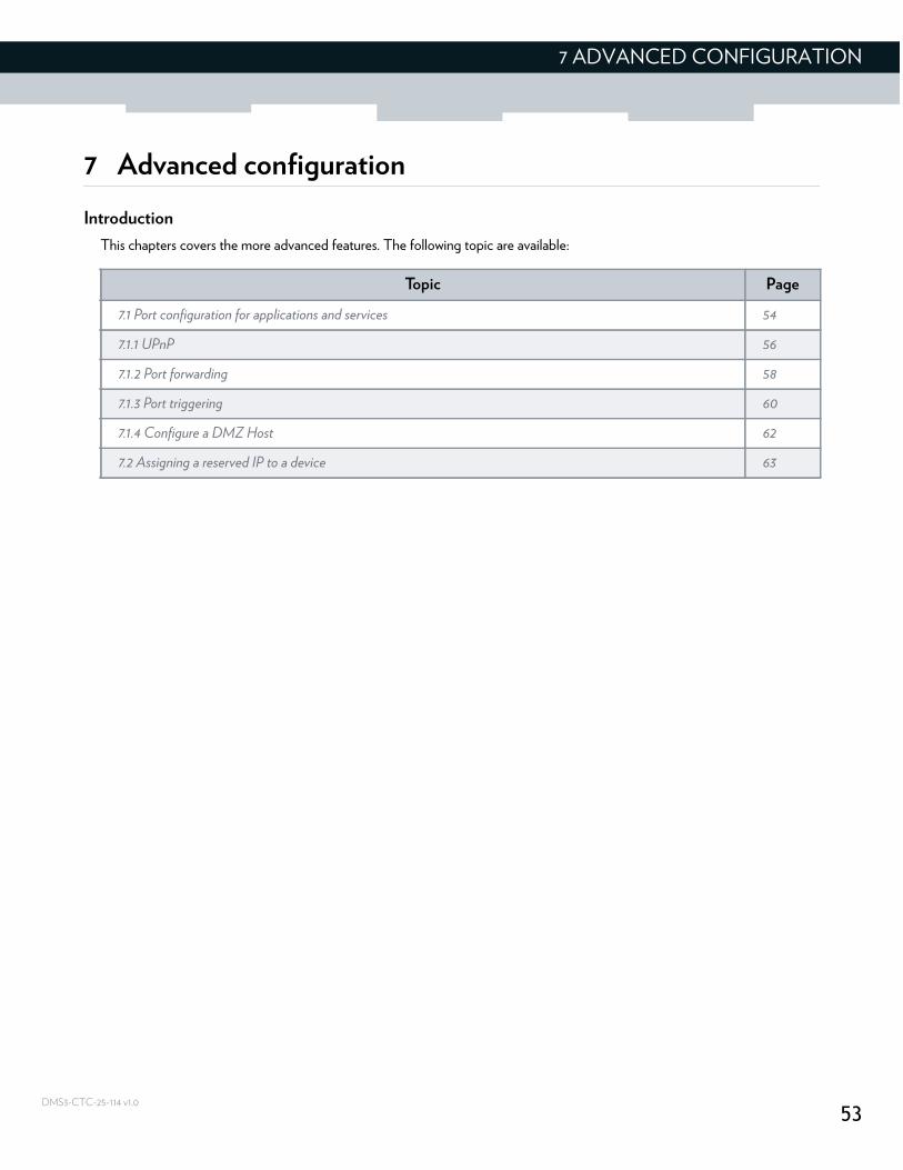
Introduction
This chapters covers the more advanced features. The following topic are available:
Topic Page
7.1 Port configuration for applications and services 54
7.1.1 UPnP 56
7.1.2 Port forwarding 58
7.1.3 Port triggering 60
7.1.4 Configure a DMZ Host 62
7.2 Assigning a reserved IP to a device 63
54
7 ADVANCED CONFIGURATION
DMS3-CTC-25-114 v1.0
7.1 Port configuration for applications and services
Introduction
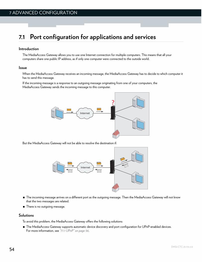
The MediaAccess Gateway allows you to use one Internet connection for multiple computers. This means that all your computers share one public IP address, as if only one computer were connected to the outside world.
Issue
When the MediaAccess Gateway receives an incoming message, the MediaAccess Gateway has to decide to which computer it has to send this message.
If the incoming message is a response to an outgoing message originating from one of your computers, the MediaAccess Gateway sends the incoming message to this computer.
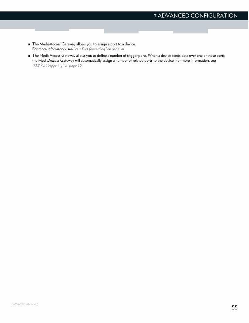
But the MediaAccess Gateway will not be able to resolve the destination if:
The incoming message arrives on a different port as the outgoing message. Then the MediaAccess Gateway will not know that the two messages are related.
There is no outgoing message.
Solutions
To avoid this problem, the MediaAccess Gateway offers the following solutions:
The MediaAccess Gateway supports automatic device discovery and port configuration for UPnP-enabled devices.For more information, see “7.1.1 UPnP” on page 56.
55
7 ADVANCED CONFIGURATION
DMS3-CTC-25-114 v1.0
The MediaAccess Gateway allows you to assign a port to a device.For more information, see “7.1.2 Port forwarding” on page 58.
The MediaAccess Gateway allows you to define a number of trigger ports. When a device sends data over one of these ports, the MediaAccess Gateway will automatically assign a number of related ports to the device. For more information, see “7.1.3 Port triggering” on page 60.
56
7 ADVANCED CONFIGURATION
DMS3-CTC-25-114 v1.0
7.1.1 UPnP
Introduction
UPnP is designed to automate the installation and configuration of a (small) network as much as possible. This means that UPnP-capable devices can join and leave a network without any effort of a network administrator.
Supported operating systems
The following operating systems support UPnP:
Windows 8
Windows 7
Windows Vista
Windows XP
UPnP and the MediaAccess Gateway
UPnP offers you the following functions:
You do not have to manually create port mappings to run services on a computer. The automatic port configuration mechanism for UPnP-enabled games and applications will do this for you. If the application is UPnP-enabled, UPnP will create these entries automatically.
You can access the Admin Tool without having to remember the address of the MediaAccess Gateway.
Enable UPnP on the MediaAccess Gateway
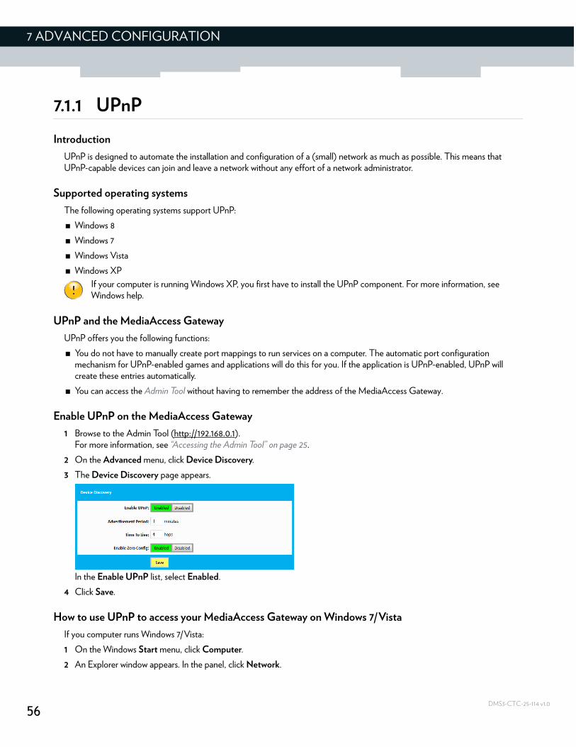
1 Browse to the Admin Tool (http://192.168.0.1).For more information, see “Accessing the Admin Tool” on page 25.
2 On the Advanced menu, click Device Discovery.
3 The Device Discovery page appears.
In the Enable UPnP list, select Enabled.
4 Click Save.
How to use UPnP to access your MediaAccess Gateway on Windows 7/Vista
If you computer runs Windows 7/Vista:
1 On the Windows Start menu, click Computer.
2 An Explorer window appears. In the panel, click Network.
If your computer is running Windows XP, you first have to install the UPnP component. For more information, see Windows help.
57
7 ADVANCED CONFIGURATION
DMS3-CTC-25-114 v1.0
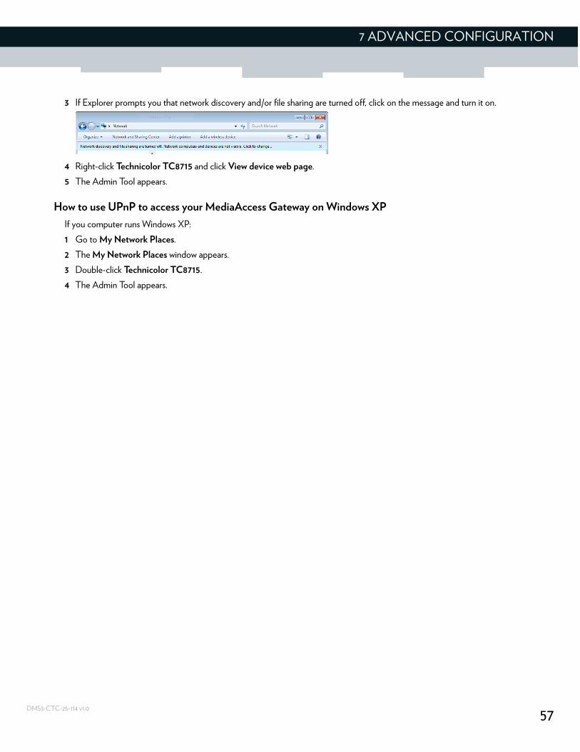
3 If Explorer prompts you that network discovery and/or file sharing are turned off, click on the message and turn it on.
4 Right-click Technicolor TC8715 and click View device web page.
5 The Admin Tool appears.
How to use UPnP to access your MediaAccess Gateway on Windows XP
If you computer runs Windows XP:
1 Go to My Network Places.
2 The My Network Places window appears.
3 Double-click Technicolor TC8715.
4 The Admin Tool appears.
58
7 ADVANCED CONFIGURATION
DMS3-CTC-25-114 v1.0
7.1.2 Port forwarding
Introduction
Port forwarding allows you to forward incoming Internet traffic arriving on a specific port to an internal IP address.
For example: if you are running a web server and the MediaAccess Gateway receives a request on port 80, this request should be forwarded to your web server.
Use a reserved IP address
The target device of the port forwarding rules will be specified by an IP address. Make sure that your device uses a fixed IP address. If you do not do this, the device might get a new IP address after some time and the port forwarding rule will no longer be applied to the device. For more information, see 7.2 Assigning a reserved IP to a device .
Procedure
Proceed as follows to do so:
1 Browse to the Admin Tool (http://192.168.0.1).For more information, see “Accessing the Admin Tool” on page 25.
2 On the left menu, click Advanced.
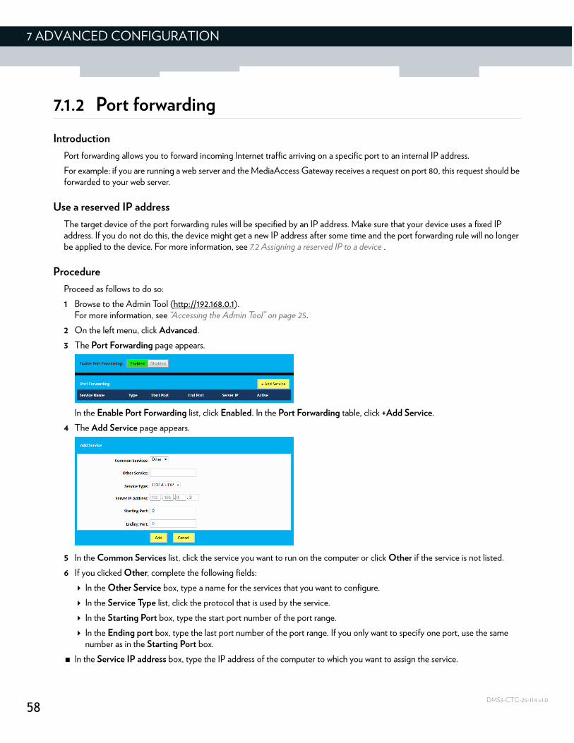
3 The Port Forwarding page appears.
In the Enable Port Forwarding list, click Enabled. In the Port Forwarding table, click +Add Service.
4 The Add Service page appears.
5 In the Common Services list, click the service you want to run on the computer or click Other if the service is not listed.
6 If you clicked Other, complete the following fields:
In the Other Service box, type a name for the services that you want to configure.
In the Service Type list, click the protocol that is used by the service.
In the Starting Port box, type the start port number of the port range.
In the Ending port box, type the last port number of the port range. If you only want to specify one port, use the same number as in the Starting Port box.
In the Service IP address box, type the IP address of the computer to which you want to assign the service.

59
7 ADVANCED CONFIGURATION
DMS3-CTC-25-114 v1.0
7 Click Add.
8 Your service is now listed in the Port Forwarding table. All incoming requests for the selected service will now be directed to the selected device. The MediaAccess Gateway also automatically configures its firewall to allow this service.
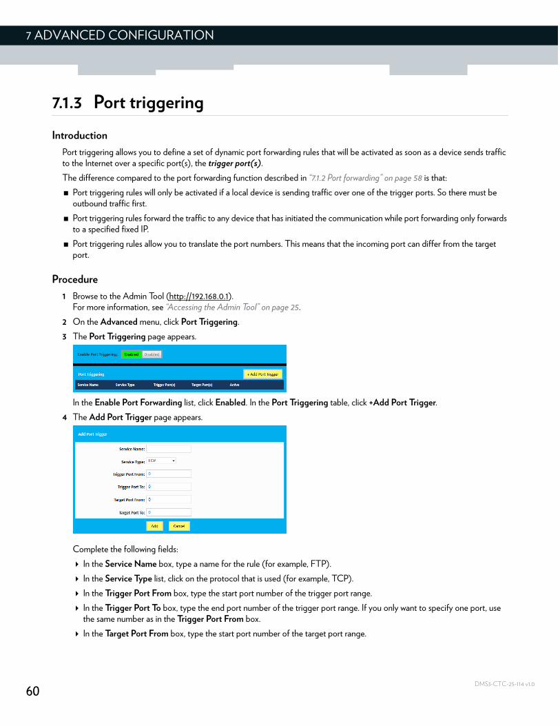
60
7 ADVANCED CONFIGURATION
DMS3-CTC-25-114 v1.0
7.1.3 Port triggering
Introduction
Port triggering allows you to define a set of dynamic port forwarding rules that will be activated as soon as a device sends traffic to the Internet over a specific port(s), the trigger port(s).
The difference compared to the port forwarding function described in “7.1.2 Port forwarding” on page 58 is that:
Port triggering rules will only be activated if a local device is sending traffic over one of the trigger ports. So there must be outbound traffic first.
Port triggering rules forward the traffic to any device that has initiated the communication while port forwarding only forwards to a specified fixed IP.
Port triggering rules allow you to translate the port numbers. This means that the incoming port can differ from the target port.
Procedure
1 Browse to the Admin Tool (http://192.168.0.1).For more information, see “Accessing the Admin Tool” on page 25.
2 On the Advanced menu, click Port Triggering.
3 The Port Triggering page appears.
In the Enable Port Forwarding list, click Enabled. In the Port Triggering table, click +Add Port Trigger.
4 The Add Port Trigger page appears.
Complete the following fields:
In the Service Name box, type a name for the rule (for example, FTP).
In the Service Type list, click on the protocol that is used (for example, TCP).
In the Trigger Port From box, type the start port number of the trigger port range.
In the Trigger Port To box, type the end port number of the trigger port range. If you only want to specify one port, use the same number as in the Trigger Port From box.
In the Target Port From box, type the start port number of the target port range.
61
7 ADVANCED CONFIGURATION
DMS3-CTC-25-114 v1.0
In the Target Port To box, type the end port number of the target port range. If you only want to specify one port, use the same number as in the Target Port From box.
5 Click Add.
6 Your service is now listed in the Port Triggering table. All incoming requests for the selected service will now be directed to the selected device. The MediaAccess Gateway also automatically configures its firewall to allow this service.
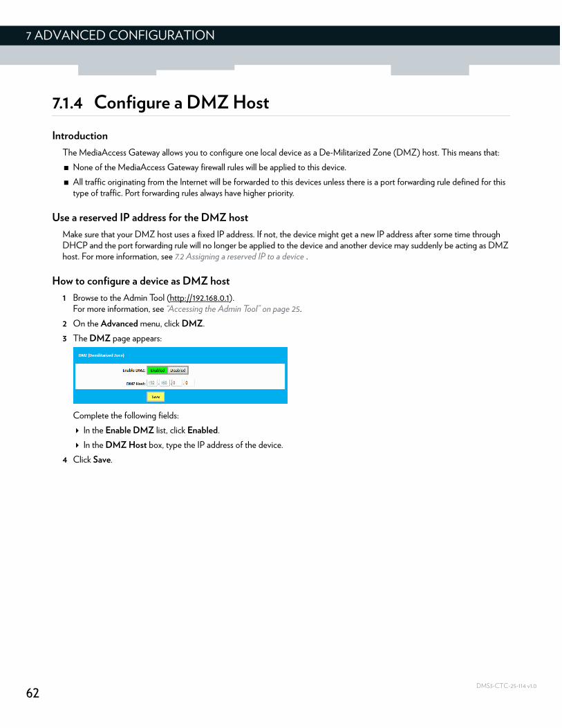
62
7 ADVANCED CONFIGURATION
DMS3-CTC-25-114 v1.0
7.1.4 Configure a DMZ Host
Introduction
The MediaAccess Gateway allows you to configure one local device as a De-Militarized Zone (DMZ) host. This means that:
None of the MediaAccess Gateway firewall rules will be applied to this device.
All traffic originating from the Internet will be forwarded to this devices unless there is a port forwarding rule defined for this type of traffic. Port forwarding rules always have higher priority.
Use a reserved IP address for the DMZ host
Make sure that your DMZ host uses a fixed IP address. If not, the device might get a new IP address after some time through DHCP and the port forwarding rule will no longer be applied to the device and another device may suddenly be acting as DMZ host. For more information, see 7.2 Assigning a reserved IP to a device .
How to configure a device as DMZ host
1 Browse to the Admin Tool (http://192.168.0.1).For more information, see “Accessing the Admin Tool” on page 25.
2 On the Advanced menu, click DMZ.
3 The DMZ page appears:
Complete the following fields:
In the Enable DMZ list, click Enabled.
In the DMZ Host box, type the IP address of the device.
4 Click Save.
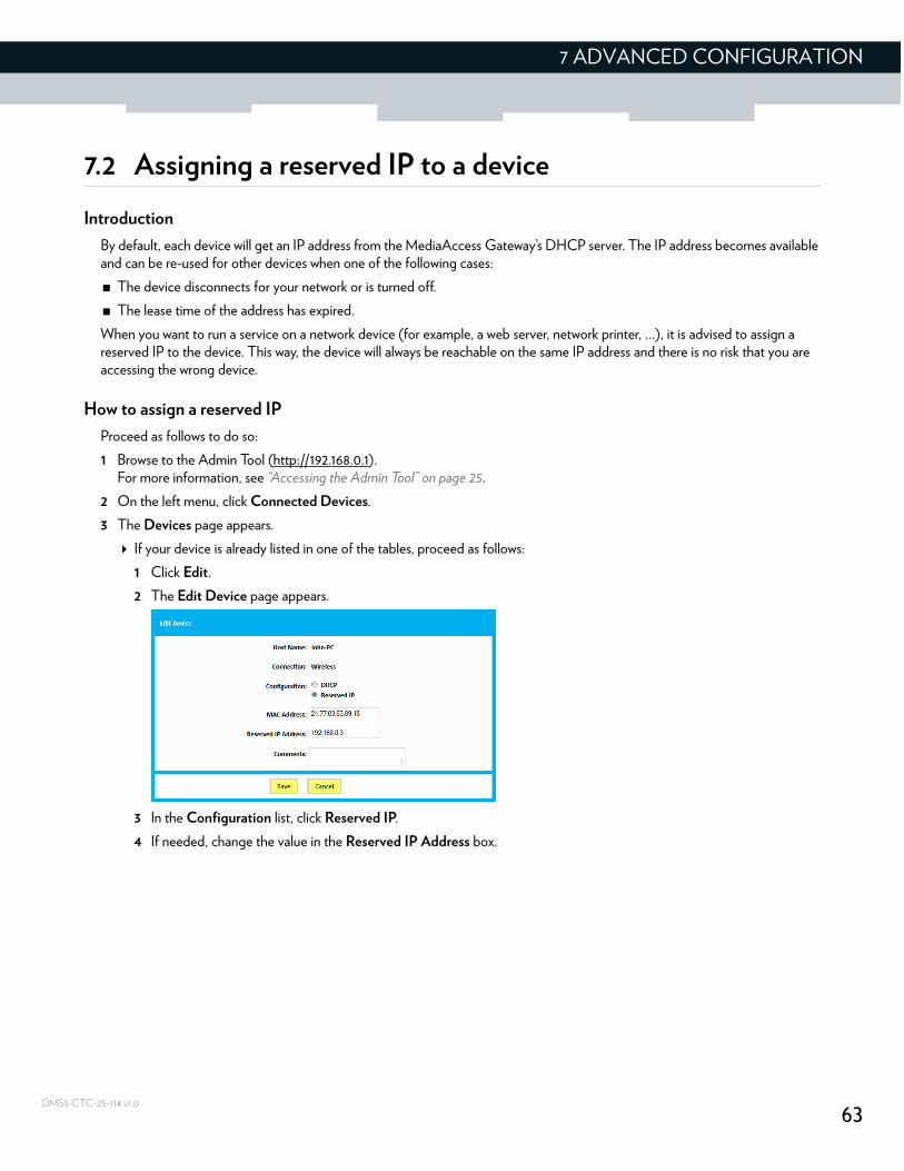
63
7 ADVANCED CONFIGURATION
DMS3-CTC-25-114 v1.0
7.2 Assigning a reserved IP to a device
Introduction
By default, each device will get an IP address from the MediaAccess Gateway’s DHCP server. The IP address becomes available and can be re-used for other devices when one of the following cases:
The device disconnects for your network or is turned off.
The lease time of the address has expired.
When you want to run a service on a network device (for example, a web server, network printer, …), it is advised to assign a reserved IP to the device. This way, the device will always be reachable on the same IP address and there is no risk that you are accessing the wrong device.
How to assign a reserved IP
Proceed as follows to do so:
1 Browse to the Admin Tool (http://192.168.0.1).For more information, see “Accessing the Admin Tool” on page 25.
2 On the left menu, click Connected Devices.
3 The Devices page appears.
If your device is already listed in one of the tables, proceed as follows:
1 Click Edit.
2 The Edit Device page appears.
3 In the Configuration list, click Reserved IP.
4 If needed, change the value in the Reserved IP Address box.
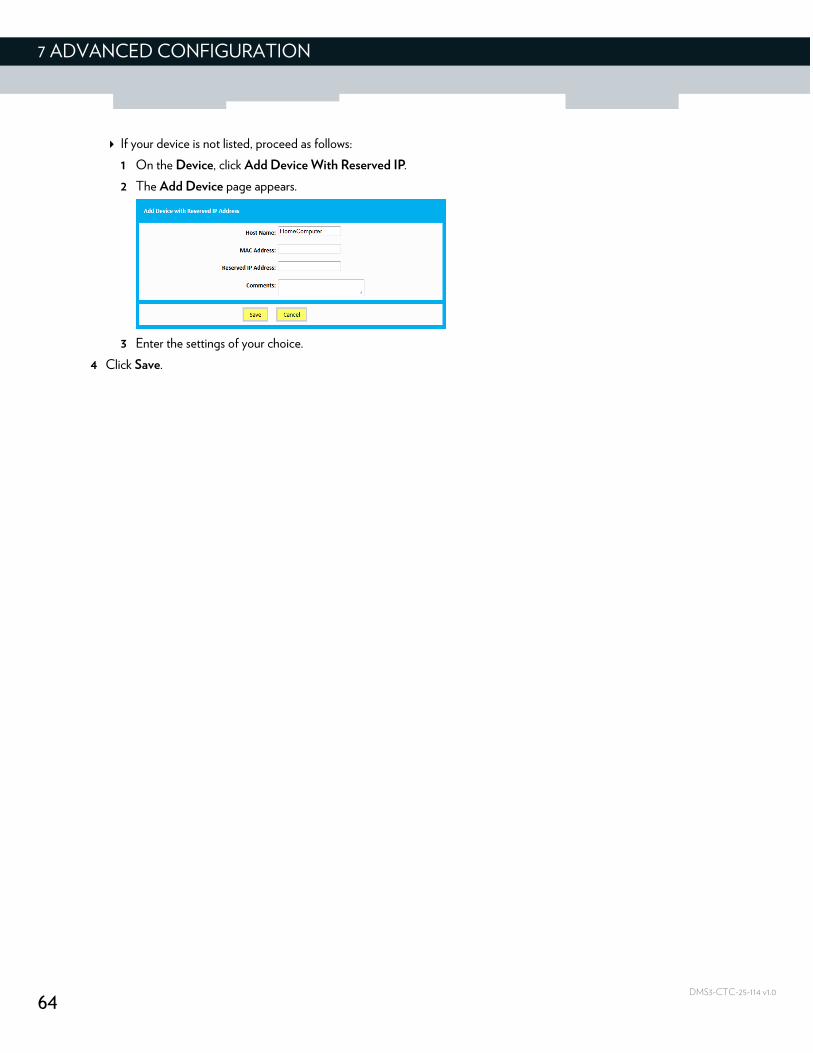
64
7 ADVANCED CONFIGURATION
DMS3-CTC-25-114 v1.0
If your device is not listed, proceed as follows:
1 On the Device, click Add Device With Reserved IP.
2 The Add Device page appears.
3 Enter the settings of your choice.
4 Click Save.
65
8 SUPPORT
DMS3-CTC-25-114 v1.0
8 Support
Introduction
This chapter suggests solutions for issues that you may encounter while installing, configuring or using your MediaAccess Gateway.
If the suggestions do not resolve the problem, look at the support pages on www.technicolor.com or contact your service provider.
Topics
This chapter describes the following topics:
Topic Page
8.1 Wireless connection troubleshooting 66
8.2 Network diagnostic tools 69
8.3 MediaAccess Gateway reset and restore options 70
66
8 SUPPORT
DMS3-CTC-25-114 v1.0
8.1 Wireless connection troubleshooting
No wireless connectivity
Try the following:
Make sure that the wireless client is enabled (message like “radio on”).
Make sure that the wireless client is configured with the correct wireless settings (Network Name, security settings).
If the signal is low or not available, try to reposition the MediaAccess Gateway.
Make sure that the wireless client supports the wireless band, protocol and the selected wireless security that are currently used by the access point.
Change the wireless channel.
Make sure that the access point is enabled.For more information, see “Make sure that the wireless access point is enabled” on page 67.
Poor wireless connectivity or range
Try the following:
Check the signal strength, indicated by the wireless client manager. If the signal is low, try to reposition the MediaAccess Gateway.
If you are connected to the 5 GHz access point, try connecting to the 2.4 GHz access point instead.
Change the wireless channel.
Use WPAWPA2-PSK (TKIP/AES) as encryption.For more information, see “4.1 How to configure the wireless settings” on page 32.
Change the wireless channel
Proceed as follows:
1 Browse to the Admin Tool (http://192.168.0.1).For more information, see “Accessing the Admin Tool” on page 25.
2 Under Gateway, click Connection and then click WiFi.
3 The WiFi page appears. Click the Edit button next to the access point that you want to modify.
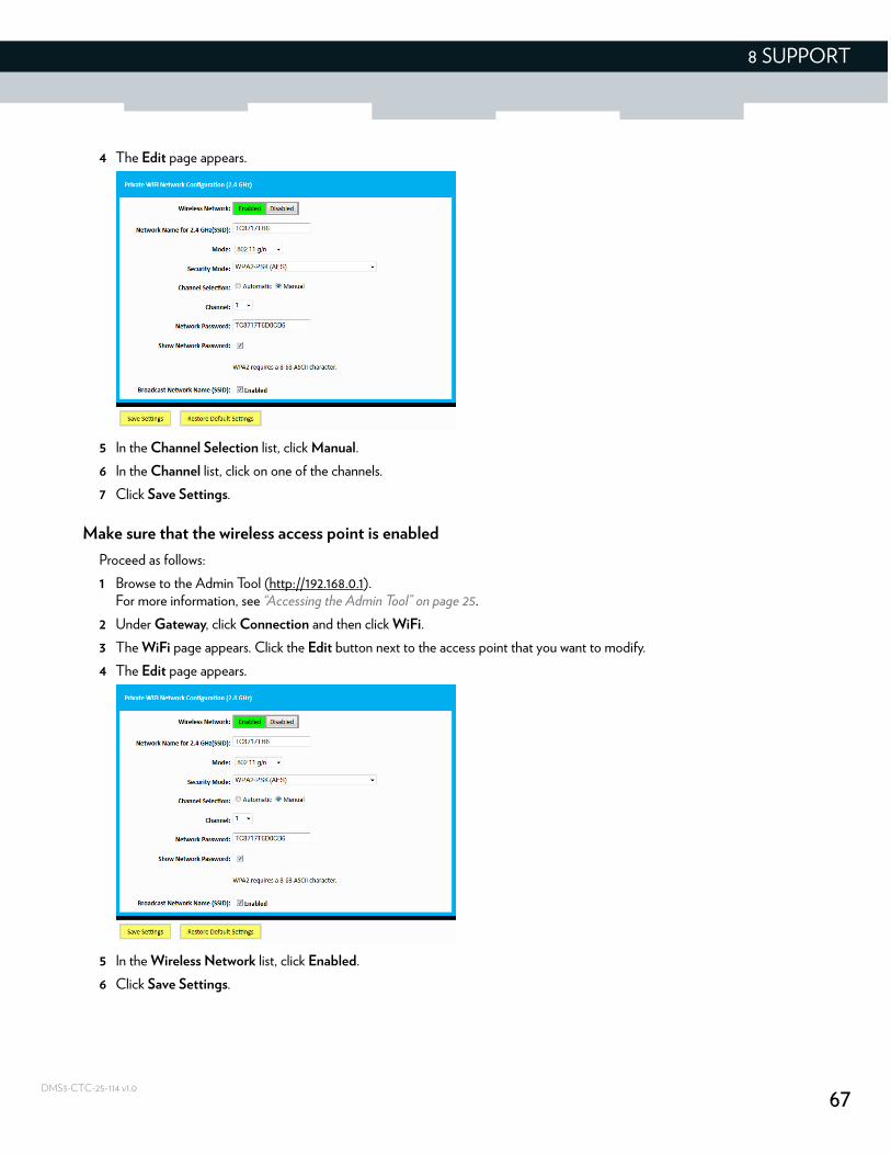
67
8 SUPPORT
DMS3-CTC-25-114 v1.0
4 The Edit page appears.
5 In the Channel Selection list, click Manual.
6 In the Channel list, click on one of the channels.
7 Click Save Settings.
Make sure that the wireless access point is enabled
Proceed as follows:
1 Browse to the Admin Tool (http://192.168.0.1).For more information, see “Accessing the Admin Tool” on page 25.
2 Under Gateway, click Connection and then click WiFi.
3 The WiFi page appears. Click the Edit button next to the access point that you want to modify.
4 The Edit page appears.
5 In the Wireless Network list, click Enabled.
6 Click Save Settings.
68
8 SUPPORT
DMS3-CTC-25-114 v1.0
Cannot connect via WPS
If you are having trouble connecting your wireless client via WPS, try to configure it manually. For more information, see “2.4.2 How to manually connect your wireless client” on page 20.
69
8 SUPPORT
DMS3-CTC-25-114 v1.0
8.2 Network diagnostic tools
Introduction
The Admin Tool offers a number of diagnostics tools to test your network connectivity.
How to access the network diagnostics tools
1 Browse to the Admin Tool (http://192.168.0.1).For more information, see “Accessing the Admin Tool” on page 25.
2 On the Troubleshooting menu, click Diagnostic Tools.
3 The Network Diagnostic Tools page appears. The following tools are available:
Test Connectivity Results
Check for IPv4 Address Results
Check for IPv6 Address Results
70
8 SUPPORT
DMS3-CTC-25-114 v1.0
8.3 MediaAccess Gateway reset and restore options
Reset
By performing a reset you will restart a specific set of services (or the complete MediaAccess Gateway).
Restore
By performing a restore you will reset a specific set of services (or the complete MediaAccess Gateway) and reapply their factory default settings.
Methods
You can choose between:
Performing a reset (restart) or restore via the Admin Tool.With this method you can choose to only reset (restart) or restore a specific module of the MediaAccess Gateway or perform a complete reset/restore of the MediaAccess Gateway.
Reset/restore the MediaAccess Gateway via the Reset buttonWith this method you can only perform a complete reset (restart) or restore of the MediaAccess Gateway
Performing a reset (restart) or restore via the Admin Tool
Proceed as follows:
1 Browse to the Admin Tool (http://192.168.0.1).For more information, see “Accessing the Admin Tool” on page 25.
2 On the Troubleshooting menu, click Reset/Reboot Gateway.
3 The Reset/Reboot Gateway page appears. Click:
Reset to restart the MediaAccess Gateway.
Reset WiFi Module to restart just the wireless module only.
Reset WiFi Router to restart the wireless and router modules.
Restore WiFi Settings to activate the MediaAccess Gateway default settings for wireless only. All changes to the default wireless settings will be undone.
Restore Factory Settings to activate all MediaAccess Gateway default settings. All changes to the default settings will be undone.
4 The MediaAccess Gateway prompts you to confirm your choice. Click OK.
5 If you selected Restore Factory Settings, the MediaAccess Gateway will restart. In all other cases, no restart is needed.
Reset/restore the MediaAccess Gateway via the Reset button
Proceed as follows:
1 Make sure that the MediaAccess Gateway is turned on.
2 If you want to:
A reset to factory default settings deletes all configuration changes you made. Therefore, after the reset a reconfiguration of your MediaAccess Gateway or a restore of a previously saved configuration (see “Restoring a previously saved configuration” on page 29) will be needed.
Also your wireless clients will have to be re-associated, as described in “2.4 Connect your wireless devices” on page 17.
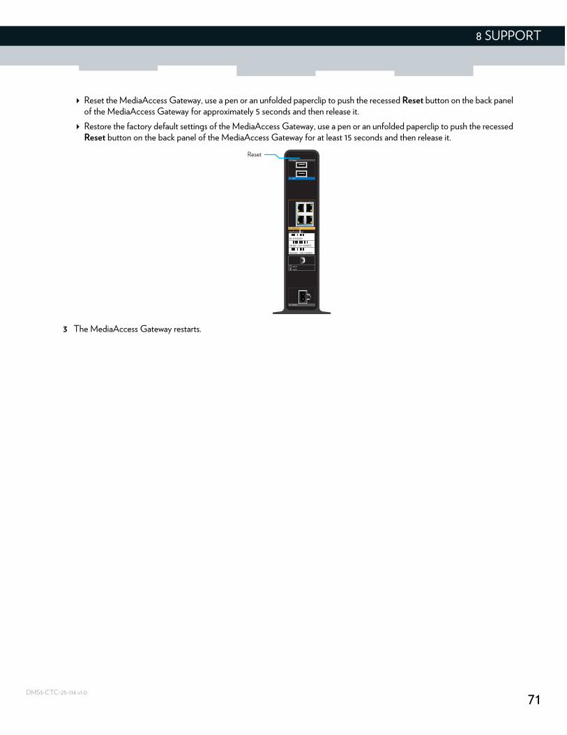
71
8 SUPPORT
DMS3-CTC-25-114 v1.0
Reset the MediaAccess Gateway, use a pen or an unfolded paperclip to push the recessed Reset button on the back panel of the MediaAccess Gateway for approximately 5 seconds and then release it.
Restore the factory default settings of the MediaAccess Gateway, use a pen or an unfolded paperclip to push the recessed Reset button on the back panel of the MediaAccess Gateway for at least 15 seconds and then release it.
3 The MediaAccess Gateway restarts.
Reset

72
8 SUPPORT
DMS3-CTC-25-114 v1.0


Copyright 2015 Technicolor. All rights reserved. All tradenames referenced are service marks, trademarks, or registered trademarks of their respective companies. Specifications subject to change without notice.DMS3-CTC-25-114 v1.0
TECHNICOLOR WORLDWIDE HEADQUARTERS1-5, rue Jeanne d’Arc92130 Issy-les-MoulineauxFrance
www.technicolor.com
![A Smart Kitchen for Ambient Assisted Living€¦ · Ambient Assisted Living Innovation Alliance (The AAliance) proposes three macro scenarios for AAL development [7]: AAL4persons,](https://img.pdfslide.net/doc/110x75/5f20035439304e457957228e/a-smart-kitchen-for-ambient-assisted-living-ambient-assisted-living-innovation-alliance.jpg)
![winprotocoldoc.blob.core.windows.net... · Web view[MS-DLNHND]: Digital Living Network Alliance (DLNA) Networked Device Interoperability Guidelines: Microsoft Extensions. Intellectual](https://img.pdfslide.net/doc/110x75/5abefc257f8b9add5f8d3b07/viewms-dlnhnd-digital-living-network-alliance-dlna-networked-device-interoperability.jpg)


![[MS-DLNHND]: Digital Living Network Alliance (DLNA ... · PDF fileDigital Living Network Alliance (DLNA) Networked Device Interoperability Guidelines: ... Networked Device Interoperability](https://img.pdfslide.net/doc/110x75/5aaaca157f8b9a90188e93d6/ms-dlnhnd-digital-living-network-alliance-dlna-living-network-alliance-dlna.jpg)


![[MS-DLNHND]: Digital Living Network Alliance (DLNA](https://img.pdfslide.net/doc/110x75/61bd26ea61276e740b0fe465/ms-dlnhnd-digital-living-network-alliance-dlna-.jpg)

