Embed Size (px)
Citation preview
Setup Guide
NOS 3.0.312-Jun-2013
Copyright | Setup Guide | NOS 3.0.3 | 2
Notice
Copyright
Copyright 2013 Nutanix, Inc.
Nutanix, Inc.1740 Technology Drive, Suite 400San Jose, CA 95110
All rights reserved. This product is protected by U.S. and international copyright and intellectual propertylaws. Nutanix is a trademark of Nutanix, Inc. in the United States and/or other jurisdictions. All other marksand names mentioned herein may be trademarks of their respective companies.
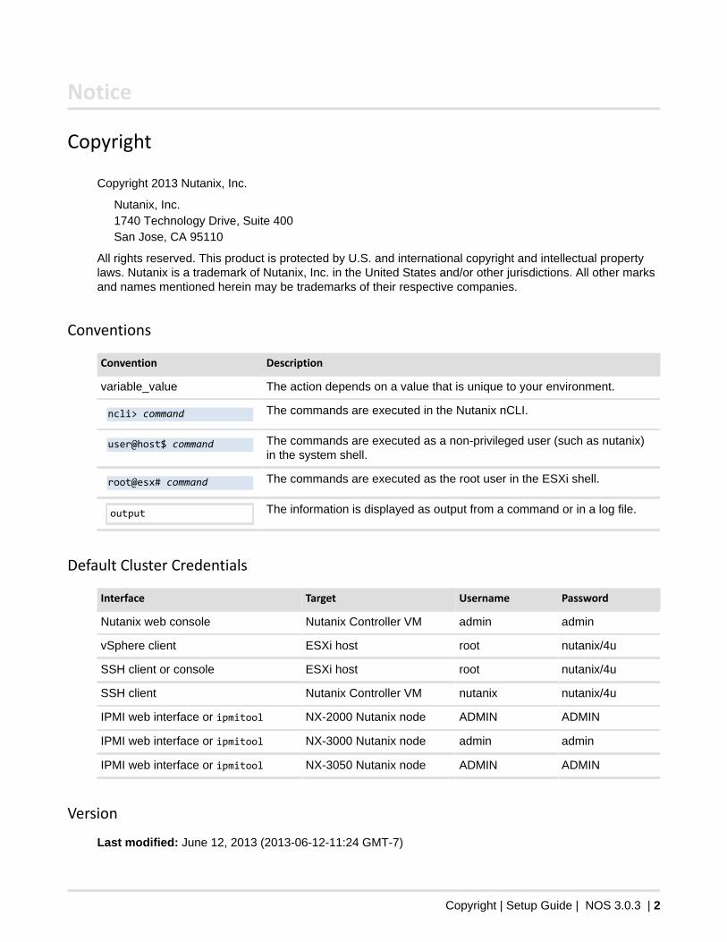
Conventions
Convention Description
variable_value The action depends on a value that is unique to your environment.
ncli> command The commands are executed in the Nutanix nCLI.
user@host$ command The commands are executed as a non-privileged user (such as nutanix)in the system shell.
root@esx# command The commands are executed as the root user in the ESXi shell.
output The information is displayed as output from a command or in a log file.
Default Cluster Credentials
Interface Target Username Password
Nutanix web console Nutanix Controller VM admin admin
vSphere client ESXi host root nutanix/4u
SSH client or console ESXi host root nutanix/4u
SSH client Nutanix Controller VM nutanix nutanix/4u
IPMI web interface or ipmitool NX-2000 Nutanix node ADMIN ADMIN
IPMI web interface or ipmitool NX-3000 Nutanix node admin admin
IPMI web interface or ipmitool NX-3050 Nutanix node ADMIN ADMIN
Version
Last modified: June 12, 2013 (2013-06-12-11:24 GMT-7)
3
Contents
Overview........................................................................................................................... 4Setup Checklist....................................................................................................................................4Factory-Installed Components.............................................................................................................4Reserved IP Addresses...................................................................................................................... 5Network Information............................................................................................................................ 5
1: IP Address Configuration.......................................................................6To Configure the Cluster.....................................................................................................................6To Configure the Cluster in a VLAN-Segmented Network................................................................. 9
To Assign VLAN Tags to Nutanix Nodes.................................................................................9
2: Storage Configuration.......................................................................... 11To Create the Datastore................................................................................................................... 11
3: vCenter Configuration.......................................................................... 13To Create a Nutanix Cluster in vCenter........................................................................................... 13To Add a Nutanix Node to vCenter.................................................................................................. 16vSphere Cluster Settings...................................................................................................................17
4: Final Configuration............................................................................... 19To Set the Timezone of the Cluster................................................................................................. 19To Make Optional Settings................................................................................................................19Diagnostics VMs................................................................................................................................20
To Run a Test Using the Diagnostics VMs............................................................................20Diagnostics Output................................................................................................................. 21
To Test Email Alerts......................................................................................................................... 22To Check the Status of Cluster Services......................................................................................... 22
Appendix A: Manual IP Address Configuration..................................... 23To Verify IPv6 Link-Local Connectivity............................................................................................. 23To Configure the Cluster (Manual)................................................................................................... 24Remote Console IP Address Configuration...................................................................................... 26
To Configure the Remote Console IP Address (NX-3050).................................................... 26To Configure the Remote Console IP Address (NX-3000).................................................... 27To Configure the Remote Console IP Address (NX-2000).................................................... 27To Configure the Remote Console IP Address (command line)............................................ 28
To Configure a Host IP Address.......................................................................................................29To Configure the Controller VM IP Address..................................................................................... 29
Overview | Setup Guide | NOS 3.0.3 | 4
Overview
This guide provides step-by-step instructions on the post-shipment configuration of a Nutanix CompleteCluster.
Nutanix support recommends that you review field advisories on the support portal before installing acluster.
Setup Checklist
Confirm network settings with customer.
Network Information on page 5
Unpack and rack cluster hardware.
Refer to the Physical Installation Guide for your hardware model
Connect network and power cables.
Refer to the Physical Installation Guide for your hardware model
Assign IP addresses to all nodes in the cluster.
IP Address Configuration on page 6
Configure storage for the cluster.
Storage Configuration on page 11
Add the vSphere hosts to the customer vCenter.
vCenter Configuration on page 13
Set the timezone of the cluster.
To Set the Timezone of the Cluster on page 19
Make optional configurations.
To Make Optional Settings on page 19
Run a performance diagnostic.
Diagnostics VMs on page 20
Test email alerts.
To Test Email Alerts on page 22
Confirm that the cluster is running.
To Check the Status of Cluster Services on page 22
Factory-Installed Components
The components listed here are configured by the Nutanix manufacturing process. Do not modify any ofthese components except under the direction of Nutanix support.
Overview | Setup Guide | NOS 3.0.3 | 5
Caution: Modifying any of the settings listed here may render your cluster inoperable.
In particular, do not under any circumstances use the Reset System Configuration option ofESXi or delete the Nutanix Controller VM.
Nutanix Software
• Local datastore name• Settings and contents of any Controller VM, including the name
Important: If you create vSphere resource pools, Nutanix Controller VMs must have the topshare.
ESXi Settings
• NFS settings• VM swapfile location• VM startup/shutdown order• iSCSI software adapter settings• vSwitchNutanix standard virtual switch• vmk0 interface in port group "Management Network"• Firewall disabled
Reserved IP Addresses
The Nutanix cluster uses the following IP addresses for internal communication:
• 192.168.5.1• 192.168.5.2• 192.168.5.254
Important: The ESXi and CVM interfaces on vSwitch0 cannot use IP addresses in any subnetsthat overlap with subnet 192.168.5.0/24.
Network Information
Confirm the following network information with the customer before the new block or blocks are connectedto the customer network.
• 10 Gbps Ethernet ports [NX-3000: 2 per node/8 per block] [NX-2000: 1 per node/4 per block]• (optional) 1 Gbps Ethernet ports [1-2 per node/4-8 per block]• 10/100 Mbps Ethernet ports [1 per node/4 per block]• Default Gateway• Subnet mask• (optional) VLAN ID• NTP servers• DNS domain• DNS servers• Host servers IP Addresses (remote console) [1 per node/4 per block]• Host servers IP Addresses (hypervisor management) [1 per node/4 per block]• Nutanix Controller VMs IP addresses [1 per node/4 per block]• Reverse SSH port (outgoing connection to nsc.nutanix.com) [default 8443]• (optional) HTTP proxy for reverse SSH port
IP Address Configuration | Setup Guide | NOS 3.0.3 | 6
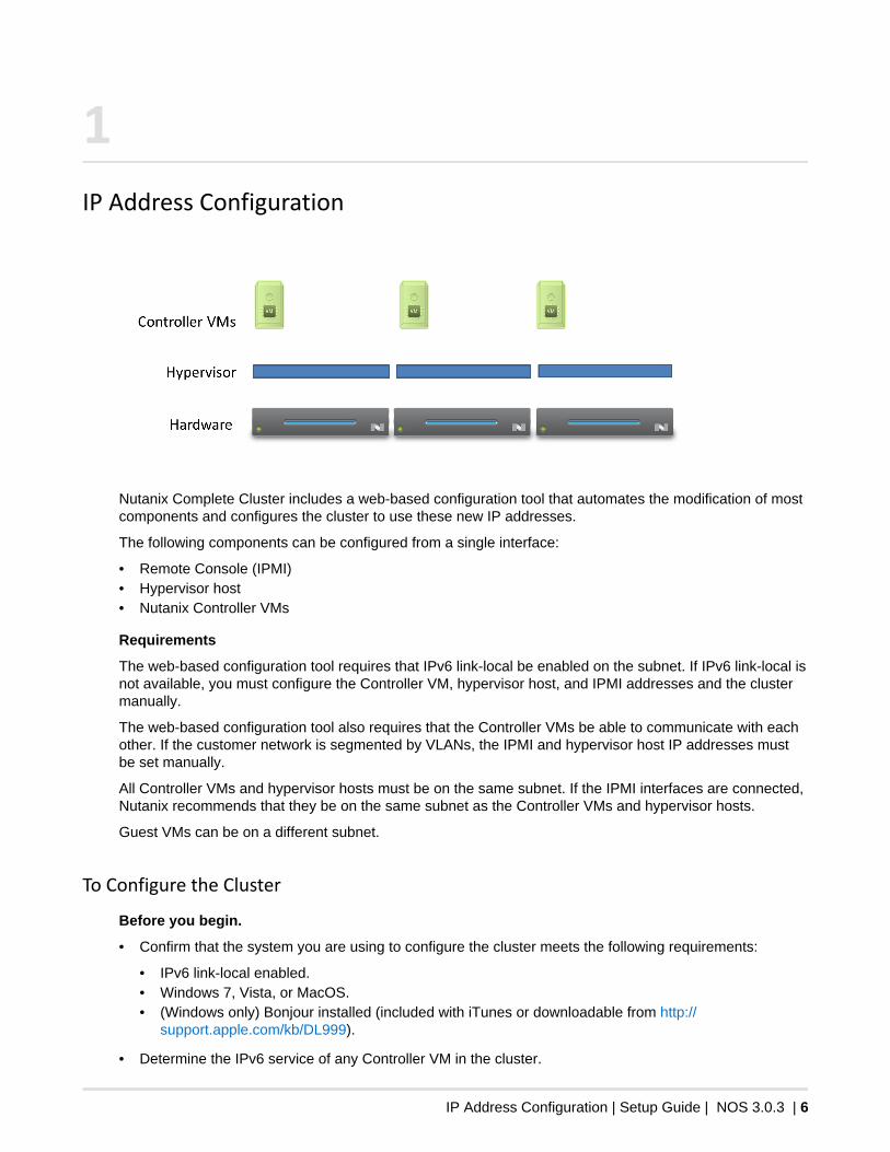
1IP Address Configuration
Nutanix Complete Cluster includes a web-based configuration tool that automates the modification of mostcomponents and configures the cluster to use these new IP addresses.
The following components can be configured from a single interface:
• Remote Console (IPMI)• Hypervisor host• Nutanix Controller VMs
Requirements
The web-based configuration tool requires that IPv6 link-local be enabled on the subnet. If IPv6 link-local isnot available, you must configure the Controller VM, hypervisor host, and IPMI addresses and the clustermanually.
The web-based configuration tool also requires that the Controller VMs be able to communicate with eachother. If the customer network is segmented by VLANs, the IPMI and hypervisor host IP addresses mustbe set manually.
All Controller VMs and hypervisor hosts must be on the same subnet. If the IPMI interfaces are connected,Nutanix recommends that they be on the same subnet as the Controller VMs and hypervisor hosts.
Guest VMs can be on a different subnet.
To Configure the Cluster
Before you begin.
• Confirm that the system you are using to configure the cluster meets the following requirements:
• IPv6 link-local enabled.• Windows 7, Vista, or MacOS.• (Windows only) Bonjour installed (included with iTunes or downloadable from http://
support.apple.com/kb/DL999).
• Determine the IPv6 service of any Controller VM in the cluster.
IP Address Configuration | Setup Guide | NOS 3.0.3 | 7
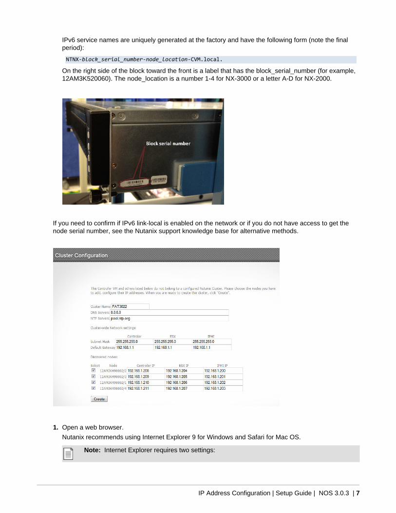
IPv6 service names are uniquely generated at the factory and have the following form (note the finalperiod):
NTNX-block_serial_number-node_location-CVM.local.
On the right side of the block toward the front is a label that has the block_serial_number (for example,12AM3K520060). The node_location is a number 1-4 for NX-3000 or a letter A-D for NX-2000.
If you need to confirm if IPv6 link-local is enabled on the network or if you do not have access to get thenode serial number, see the Nutanix support knowledge base for alternative methods.
1. Open a web browser.
Nutanix recommends using Internet Explorer 9 for Windows and Safari for Mac OS.
Note: Internet Explorer requires two settings:
IP Address Configuration | Setup Guide | NOS 3.0.3 | 8
• Disable protected mode: Go to Tools > Internet Options > Security, clear the EnableProtected Mode check box, and restart the browser.
• Enable developer mode: Press F12.
2. Navigate to http://cvm_host_name:2100/cluster_init.html.
Replace cvm_host_name with the IPv6 service name of any Controller VM that will be added to thecluster.
Following is an example URL to access the cluster creation page on a Controller VM:
http://NTNX-12AM3K520060-1-CVM.local.:2100/
If the cluster_init.html page is blank, then the Controller VM is already part of a cluster. Connect to aController VM that is not part of a cluster.
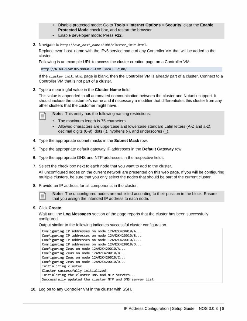
3. Type a meaningful value in the Cluster Name field.
This value is appended to all automated communication between the cluster and Nutanix support. Itshould include the customer's name and if necessary a modifier that differentiates this cluster from anyother clusters that the customer might have.
Note: This entity has the following naming restrictions:
• The maximum length is 75 characters.• Allowed characters are uppercase and lowercase standard Latin letters (A-Z and a-z),
decimal digits (0-9), dots (.), hyphens (-), and underscores (_).
4. Type the appropriate subnet masks in the Subnet Mask row.
5. Type the appropriate default gateway IP addresses in the Default Gateway row.
6. Type the appropriate DNS and NTP addresses in the respective fields.
7. Select the check box next to each node that you want to add to the cluster.
All unconfigured nodes on the current network are presented on this web page. If you will be configuringmultiple clusters, be sure that you only select the nodes that should be part of the current cluster.
8. Provide an IP address for all components in the cluster.
Note: The unconfigured nodes are not listed according to their position in the block. Ensurethat you assign the intended IP address to each node.
9. Click Create.
Wait until the Log Messages section of the page reports that the cluster has been successfullyconfigured.
Output similar to the following indicates successful cluster configuration.
Configuring IP addresses on node 12AM2K420010/A...Configuring IP addresses on node 12AM2K420010/B...Configuring IP addresses on node 12AM2K420010/C...Configuring IP addresses on node 12AM2K420010/D...Configuring Zeus on node 12AM2K420010/A...Configuring Zeus on node 12AM2K420010/B...Configuring Zeus on node 12AM2K420010/C...Configuring Zeus on node 12AM2K420010/D...Initializing cluster...Cluster successfully initialized!Initializing the cluster DNS and NTP servers...Successfully updated the cluster NTP and DNS server list
10. Log on to any Controller VM in the cluster with SSH.
IP Address Configuration | Setup Guide | NOS 3.0.3 | 9
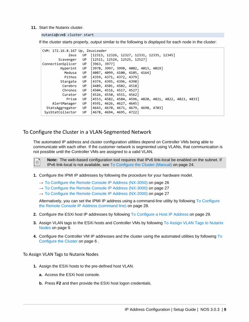
11. Start the Nutanix cluster.
nutanix@cvm$ cluster start
If the cluster starts properly, output similar to the following is displayed for each node in the cluster:
CVM: 172.16.8.167 Up, ZeusLeader Zeus UP [12313, 12326, 12327, 12331, 12335, 12345] Scavenger UP [12511, 12524, 12525, 12527]ConnectionSplicer UP [3963, 3977] Hyperint UP [3978, 3997, 3998, 4002, 4013, 4019] Medusa UP [4087, 4099, 4100, 4105, 4164] Pithos UP [4359, 4371, 4372, 4379] Stargate UP [4374, 4395, 4396, 4398] Cerebro UP [4489, 4501, 4502, 4518] Chronos UP [4504, 4516, 4517, 4527] Curator UP [4526, 4550, 4551, 4562] Prism UP [4553, 4582, 4584, 4596, 4820, 4821, 4822, 4823, 4833] AlertManager UP [4591, 4626, 4627, 4645] StatsAggregator UP [4643, 4670, 4671, 4679, 4698, 4703] SysStatCollector UP [4678, 4694, 4695, 4722]
To Configure the Cluster in a VLAN-Segmented Network
The automated IP address and cluster configuration utilities depend on Controller VMs being able tocommunicate with each other. If the customer network is segmented using VLANs, that communication isnot possible until the Controller VMs are assigned to a valid VLAN.
Note: The web-based configuration tool requires that IPv6 link-local be enabled on the subnet. IfIPv6 link-local is not available, see To Configure the Cluster (Manual) on page 24.
1. Configure the IPMI IP addresses by following the procedure for your hardware model.
→ To Configure the Remote Console IP Address (NX-3050) on page 26→ To Configure the Remote Console IP Address (NX-3000) on page 27→ To Configure the Remote Console IP Address (NX-2000) on page 27
Alternatively, you can set the IPMI IP address using a command-line utility by following To Configurethe Remote Console IP Address (command line) on page 28.
2. Configure the ESXi host IP addresses by following To Configure a Host IP Address on page 29.
3. Assign VLAN tags to the ESXi hosts and Controller VMs by following To Assign VLAN Tags to NutanixNodes on page 9.
4. Configure the Controller VM IP addresses and the cluster using the automated utilities by following ToConfigure the Cluster on page 6 .
To Assign VLAN Tags to Nutanix Nodes
1. Assign the ESXi hosts to the pre-defined host VLAN.
a. Access the ESXi host console.
b. Press F2 and then provide the ESXi host logon credentials.
IP Address Configuration | Setup Guide | NOS 3.0.3 | 10
c. Press the down arrow key until Configure Management Network is highlighted and then pressEnter.
d. Select VLAN (optional) and press Enter.
e. Type the VLAN ID specified by the customer and press Enter.
f. Press Esc and then Y to apply all changes and restart the management network.
g. Repeat this process for all remaining ESXi hosts.
2. Assign the Controller VMs to the pre-defined virtual machine VLAN.
a. Log on to an ESXi host with the vSphere client.
b. Select the host and then click the Configuration tab.
c. Click Networking.
d. Click the Properties link above vSwitch0.
e. Select VM Network and then click Edit.
f. Type the VLAN ID specified by the customer and click OK.
g. Click Close.
h. Repeat this process for all remaining ESXi hosts.
Storage Configuration | Setup Guide | NOS 3.0.3 | 11
2Storage Configuration
At the conclusion of the setup process, you will need to create the following entities:
• 1 storage pool that comprises all physical disks in the cluster.• 1 container that uses all available storage capacity in the pool.• 1 NFS datastore that is mounted from all hosts in the cluster.
A single datastore comprising all available cluster storage will suit the needs of most customers. If thecustomer requests additional NFS datastores during setup, you can create the necessary containers,and then mount them as datastores. For future datastore needs, refer the customer to the NutanixAdministration Guide.
To Create the Datastore
The following procedure is a condensed version of what is presented in the Nutanix Administration Guide.It is assumed that the cluster is in a factory state, with no existing cluster entities.
1. Sign in to the Nutanix web console.
2. Create a storage pool that contains all physical disks in the cluster.
a. Type create in the search field and select create storage pool - Admin action.
b. Type sp1 in the Name field.
c. Expand the DAS-SATA tier. If drives are shown in this tier, click the Select All check box.
d. Expand the SSD-PCIe tier. If drives are shown in this tier, click the Select All check box.
e. Expand the SSD-SATA tier. If drives are shown in this tier, click the Select All check box.
f. Click Create.
3. Create a container that uses all available storage capacity in the storage pool.
a. Right-click the sp1 storage pool and select Create Container.
b. Type nfs-ctr in the Name field.
c. Confirm that sp1 is selected in the Storage Pool list.
d. Click Create.
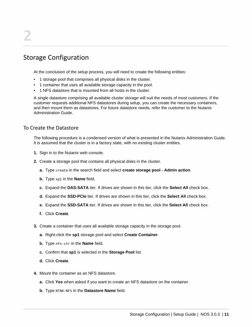
4. Mount the container as an NFS datastore.
a. Click Yes when asked if you want to create an NFS datastore on the container.
b. Type NTNX-NFS in the Datastore Name field.
Storage Configuration | Setup Guide | NOS 3.0.3 | 12
c. Click the Select All check box.
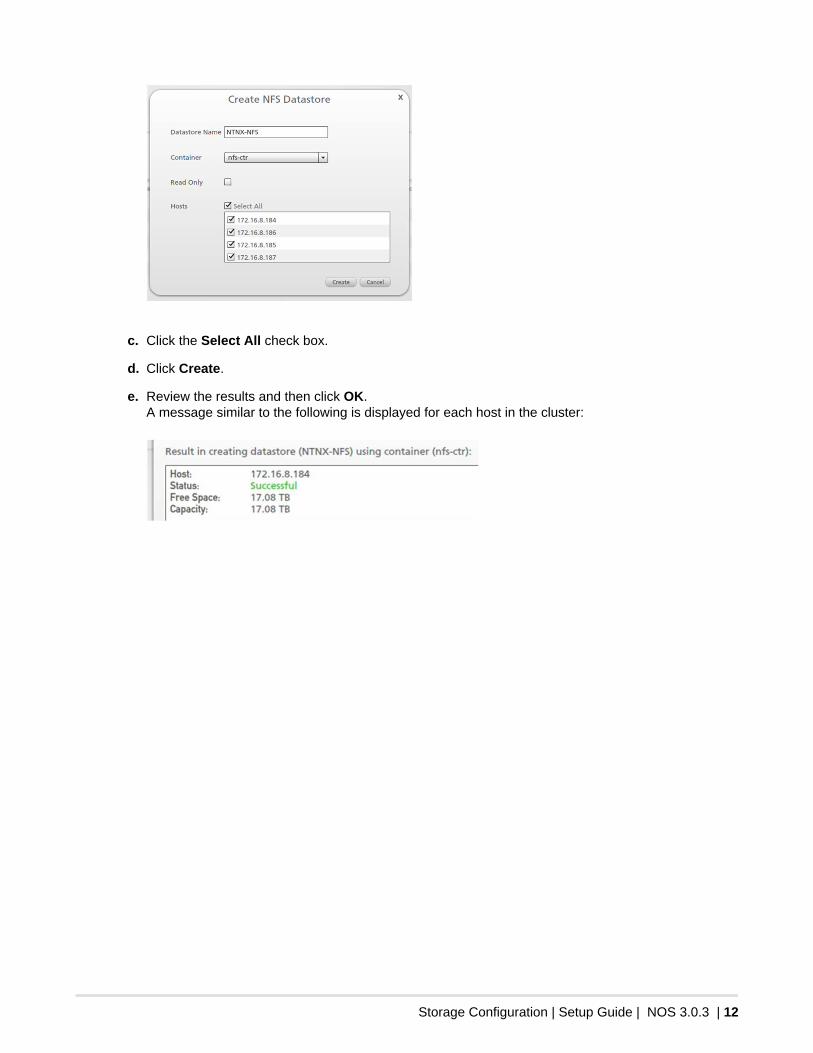
d. Click Create.
e. Review the results and then click OK.A message similar to the following is displayed for each host in the cluster:
vCenter Configuration | Setup Guide | NOS 3.0.3 | 13
3vCenter Configuration
VMware vCenter enables the centralized management of multiple ESXi hosts. The Nutanix cluster invCenter must be configured according to Nutanix best practices.
To Create a Nutanix Cluster in vCenter
1. Log on to vCenter with the vSphere client.
2. If you want the Nutanix cluster to be in its own datacenter or if there is no datacenter, click File > New >Datacenter and type a meaningful name for the datacenter, such as NTNX-DC. Otherwise, proceed to thenext step.
You can also create the Nutanix cluster within an existing datacenter.
3. Right-click the datacenter node and select New Cluster.
4. Type a meaningful name for the cluster in the Name field, such as NTNX-Cluster.
5. Select the Turn on vSphere HA check box and click Next.
6. Disable admission control and click Next.
7. Click Next on the following three pages to accept the default values.
• Virtual Machine Options• VM monitoring• VMware EVC
8. Select Store the swapfile in the same directory as the virtual machine (recommended) and clickNext.
9. Review the settings and then click Finish.
10. Add all Nutanix nodes to the vCenter cluster inventory.
See To Add a Nutanix Node to vCenter on page 16.
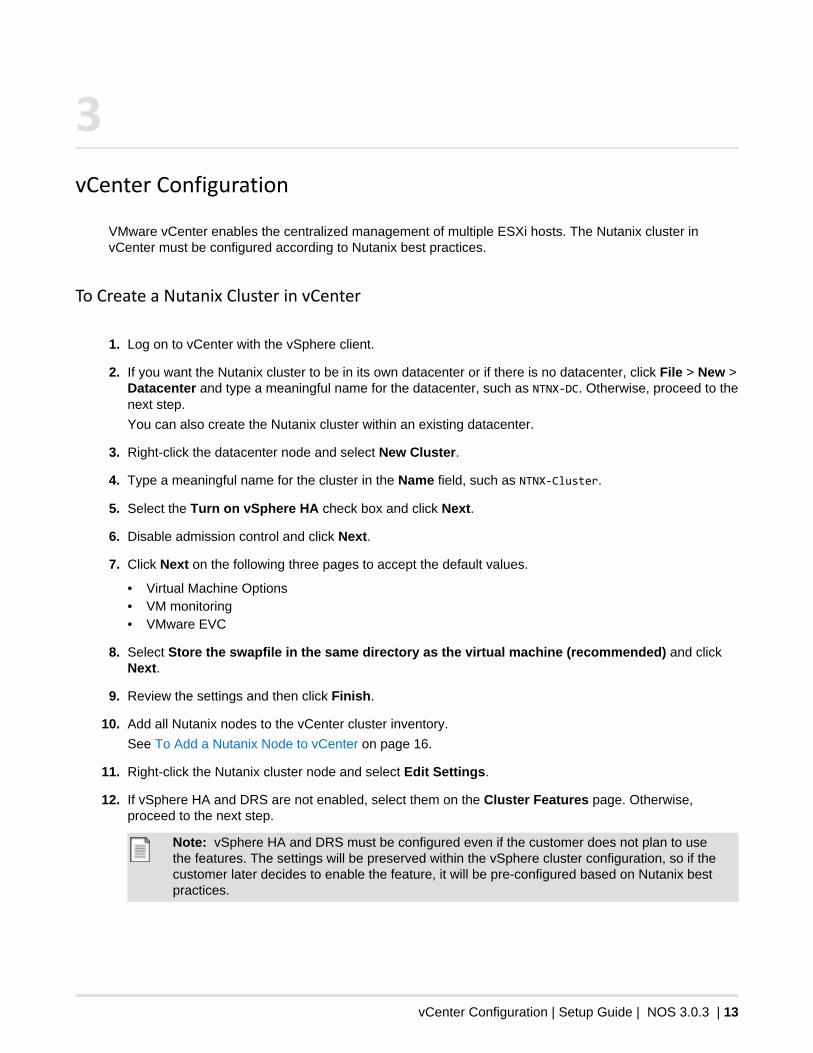
11. Right-click the Nutanix cluster node and select Edit Settings.
12. If vSphere HA and DRS are not enabled, select them on the Cluster Features page. Otherwise,proceed to the next step.
Note: vSphere HA and DRS must be configured even if the customer does not plan to usethe features. The settings will be preserved within the vSphere cluster configuration, so if thecustomer later decides to enable the feature, it will be pre-configured based on Nutanix bestpractices.
vCenter Configuration | Setup Guide | NOS 3.0.3 | 14
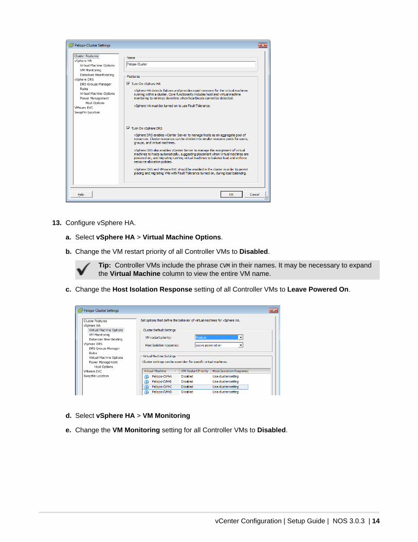
13. Configure vSphere HA.
a. Select vSphere HA > Virtual Machine Options.
b. Change the VM restart priority of all Controller VMs to Disabled.
Tip: Controller VMs include the phrase CVM in their names. It may be necessary to expandthe Virtual Machine column to view the entire VM name.
c. Change the Host Isolation Response setting of all Controller VMs to Leave Powered On.
d. Select vSphere HA > VM Monitoring
e. Change the VM Monitoring setting for all Controller VMs to Disabled.
vCenter Configuration | Setup Guide | NOS 3.0.3 | 15
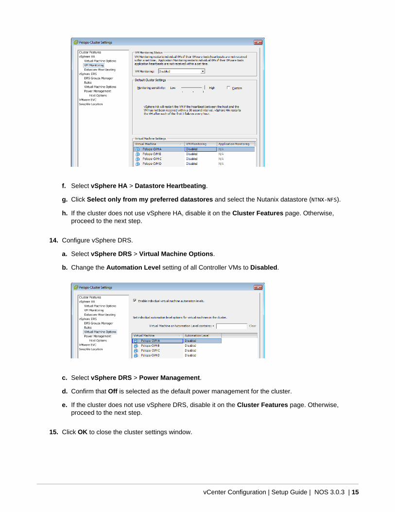
f. Select vSphere HA > Datastore Heartbeating.
g. Click Select only from my preferred datastores and select the Nutanix datastore (NTNX-NFS).
h. If the cluster does not use vSphere HA, disable it on the Cluster Features page. Otherwise,proceed to the next step.
14. Configure vSphere DRS.
a. Select vSphere DRS > Virtual Machine Options.
b. Change the Automation Level setting of all Controller VMs to Disabled.
c. Select vSphere DRS > Power Management.
d. Confirm that Off is selected as the default power management for the cluster.
e. If the cluster does not use vSphere DRS, disable it on the Cluster Features page. Otherwise,proceed to the next step.
15. Click OK to close the cluster settings window.
vCenter Configuration | Setup Guide | NOS 3.0.3 | 16
To Add a Nutanix Node to vCenter
The cluster must be configured according to Nutanix specifications given in vSphere Cluster Settings onpage 17.
Tip: Refer to Default Cluster Credentials on page 2 for the default credentials of all clustercomponents.
1. Log on to vCenter with the vSphere client.
2. Right-click the cluster and select Add Host.
3. Type the IP address of the ESXi host in the Host field.
Note: Providing the IP address of the host eliminates the chance of a FQDN mismatchbetween vCenter and the cluster configuration file.
4. Enter the ESXi host logon credentials in the Username and Password fields.
5. Click Next.
If a security or duplicate management alert appears, click Yes.
6. Review the Host Summary page and click Next.
7. Select a license to assign to the ESXi host and click Next.
8. Ensure that the Enable Lockdown Mode check box is left unselected and click Next.
Lockdown mode is not supported.
9. Click Finish.
10. Select the ESXi host and click the Configuration tab.
11. Click Storage and confirm that NFS datastores are mounted.
12. Set the Controller VM to start automatically when the ESXi host is powered on.
a. Click the Configuration tab.
b. Click Virtual Machine Startup/Shutdown in the Software frame.
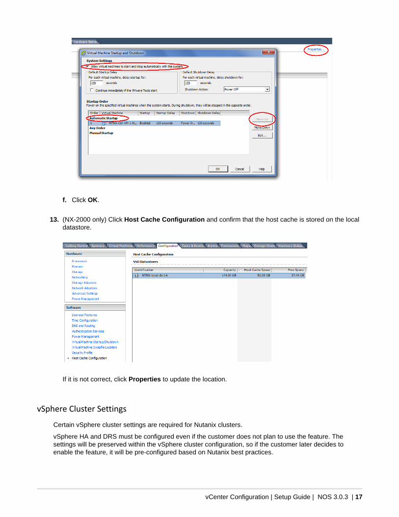
c. Select the Controller VM and click Properties.
d. Ensure that the Allow virtual machines to start and stop automatically with the system checkbox is selected.
e. If the Controller VM is listed in Manual Startup, click Move Up to move the Controller VM into theAutomatic Startup section.
vCenter Configuration | Setup Guide | NOS 3.0.3 | 17
f. Click OK.
13. (NX-2000 only) Click Host Cache Configuration and confirm that the host cache is stored on the localdatastore.
If it is not correct, click Properties to update the location.
vSphere Cluster Settings
Certain vSphere cluster settings are required for Nutanix clusters.
vSphere HA and DRS must be configured even if the customer does not plan to use the feature. Thesettings will be preserved within the vSphere cluster configuration, so if the customer later decides toenable the feature, it will be pre-configured based on Nutanix best practices.
vCenter Configuration | Setup Guide | NOS 3.0.3 | 18
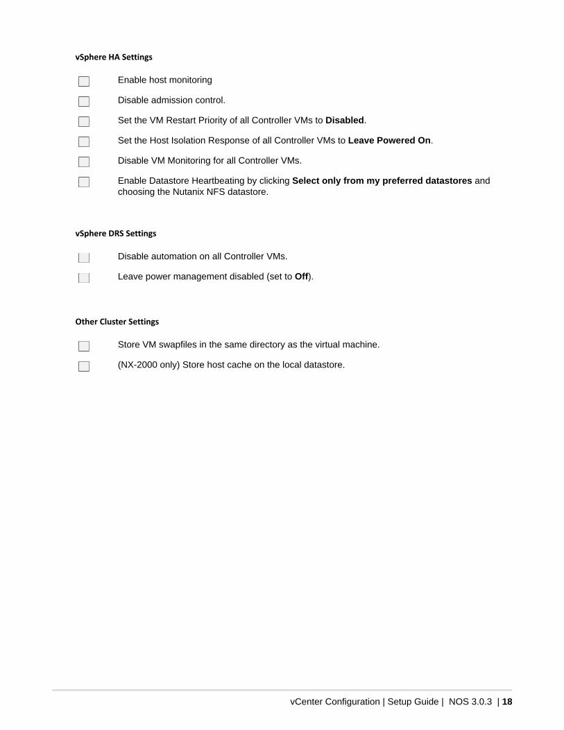
vSphere HA Settings
Enable host monitoring
Disable admission control.
Set the VM Restart Priority of all Controller VMs to Disabled.
Set the Host Isolation Response of all Controller VMs to Leave Powered On.
Disable VM Monitoring for all Controller VMs.
Enable Datastore Heartbeating by clicking Select only from my preferred datastores andchoosing the Nutanix NFS datastore.
vSphere DRS Settings
Disable automation on all Controller VMs.
Leave power management disabled (set to Off).
Other Cluster Settings
Store VM swapfiles in the same directory as the virtual machine.
(NX-2000 only) Store host cache on the local datastore.
Final Configuration | Setup Guide | NOS 3.0.3 | 19
4Final Configuration
The final steps in the Nutanix block setup are to confirm email alerts, set the timezone, and confirm that itis running.
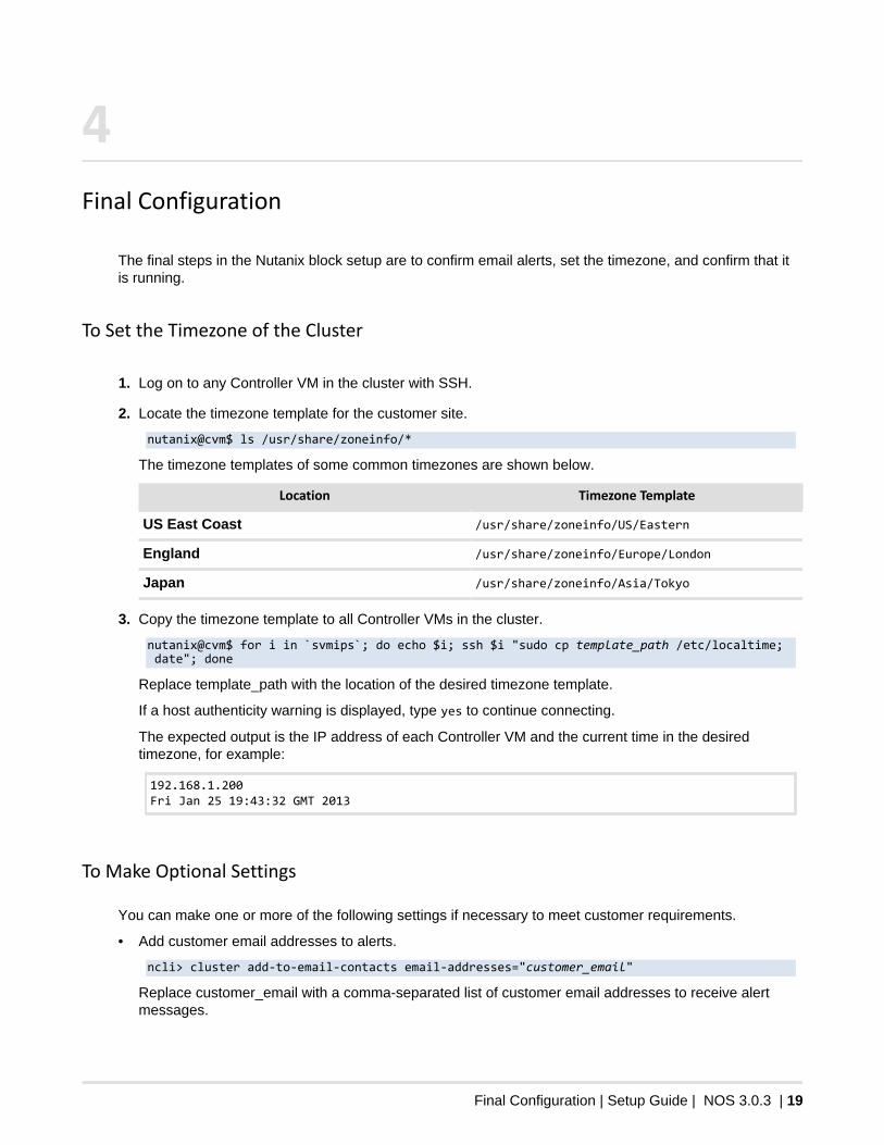
To Set the Timezone of the Cluster
1. Log on to any Controller VM in the cluster with SSH.
2. Locate the timezone template for the customer site.
nutanix@cvm$ ls /usr/share/zoneinfo/*
The timezone templates of some common timezones are shown below.
Location Timezone Template
US East Coast /usr/share/zoneinfo/US/Eastern
England /usr/share/zoneinfo/Europe/London
Japan /usr/share/zoneinfo/Asia/Tokyo
3. Copy the timezone template to all Controller VMs in the cluster.
nutanix@cvm$ for i in `svmips`; do echo $i; ssh $i "sudo cp template_path /etc/localtime; date"; done
Replace template_path with the location of the desired timezone template.
If a host authenticity warning is displayed, type yes to continue connecting.
The expected output is the IP address of each Controller VM and the current time in the desiredtimezone, for example:
192.168.1.200Fri Jan 25 19:43:32 GMT 2013
To Make Optional Settings
You can make one or more of the following settings if necessary to meet customer requirements.
• Add customer email addresses to alerts.
ncli> cluster add-to-email-contacts email-addresses="customer_email"
Replace customer_email with a comma-separated list of customer email addresses to receive alertmessages.

Final Configuration | Setup Guide | NOS 3.0.3 | 20
• Specify an outgoing SMTP server.
ncli> cluster set-smtp-server address="smtp_address"
Replace smtp_address with the IP address or name of the SMTP server to use for alert messages.• Allow access to the Nutanix web console from outside the cluster subnet.
nutanix@cvm$ for i in `svmips`; do ssh $i "sudo iptables -t filter -A WORLDLIST -p tcp -m tcp --dport 9440 -j ACCEPT && sudo iptables-save"; done
• Allow access to the Nutanix storage subsystem from outside the cluster subnet.
nutanix@cvm$ for i in `svmips`; do ssh $i "sudo iptables -t filter -A WORLDLIST -p tcp -m tcp --dport 2009 -j ACCEPT && sudo iptables-save"; done
• If the site security policy does not allow remote support tunnel, disable it.
Warning: Disabling remote support prevents Nutanix support from directly addressingcluster issues. Nutanix recommends that all customers allow email alerts because it allowsproactive support of customer issues. Do not disable remote support or email alerting unlessorganizational security policies prohibit them.
→ Web console
Under System > Remote Support, select Disabled and click OK.
→ nCLI
ncli> cluster stop-remote-support• If the site security policy does not allow email alerting, disable it.
ncli> cluster stop-email-alerts
Diagnostics VMs
Nutanix provides a diagnostics capability to allow partners and customers run performance tests on thecluster. This is a useful tool in pre-sales demonstrations of the cluster and while identifying the source ofperformance issues in a production cluster. Diagnostics should also be run as part of setup to ensure thatthe cluster is running properly before the customer takes ownership of the cluster.
The diagnostic utility deploys a VM on each node in the cluster. The Controller VMs control the diagnosticVM on their hosts and report back the results to a single system.
The diagnostics test provide the following data:
• Sequential write bandwidth• Sequential read bandwidth• Random read IOPS• Random write IOPS
Because the test creates new cluster entities, it is necessary to run a cleanup script when you are finished.
To Run a Test Using the Diagnostics VMs
Before you begin. Ensure that 10 GigE ports are active on the ESXi hosts using esxtop or vCenter. Thetests will run very slow if the nodes are not using the 10 GigE ports. For more information about this knownissue with ESXi 5.0 update 1, see VMware KB article 2030006.
1. Log on to any Controller VM in the cluster with SSH.
2. Remove the entities from any previous diagnostics.
nutanix@cvm$ ~/diagnostics/diagnostics.py cleanup
Final Configuration | Setup Guide | NOS 3.0.3 | 21
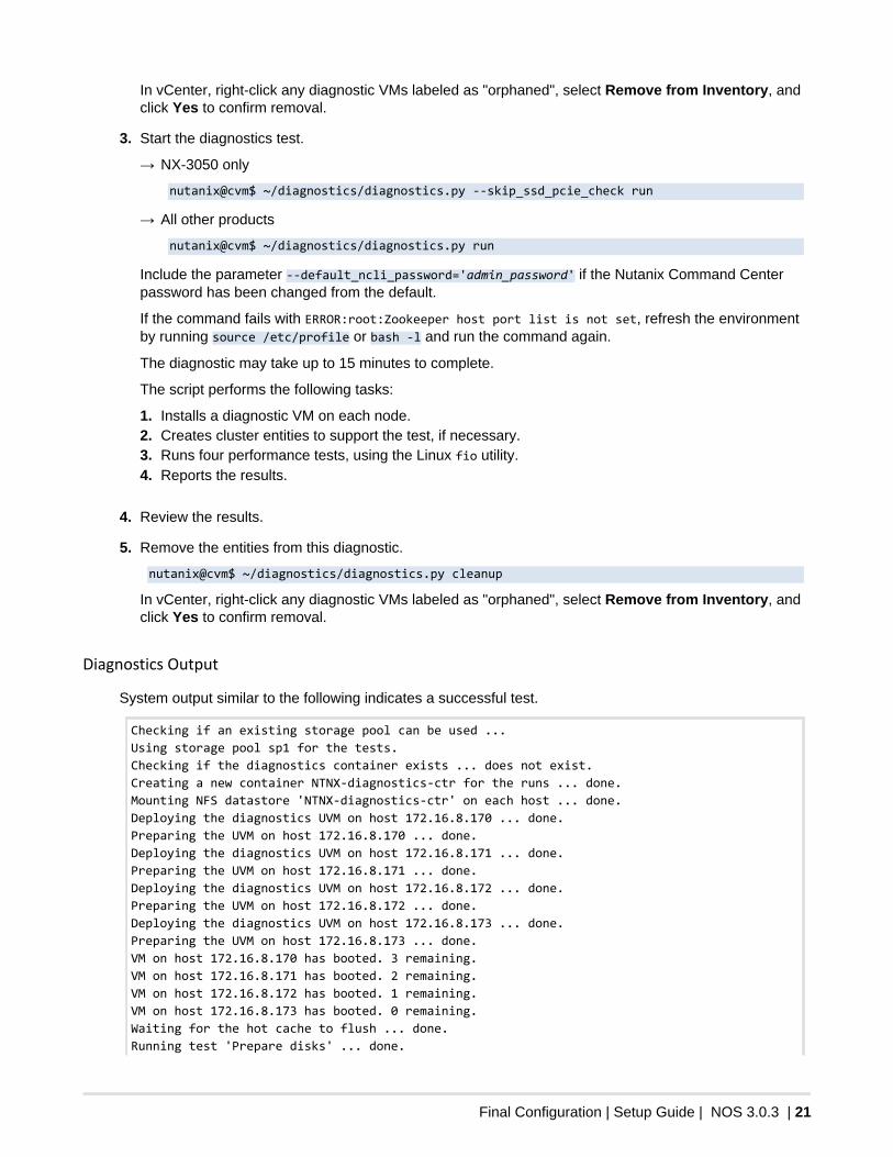
In vCenter, right-click any diagnostic VMs labeled as "orphaned", select Remove from Inventory, andclick Yes to confirm removal.
3. Start the diagnostics test.
→ NX-3050 only
nutanix@cvm$ ~/diagnostics/diagnostics.py --skip_ssd_pcie_check run
→ All other products
nutanix@cvm$ ~/diagnostics/diagnostics.py run
Include the parameter --default_ncli_password='admin_password' if the Nutanix Command Centerpassword has been changed from the default.
If the command fails with ERROR:root:Zookeeper host port list is not set, refresh the environmentby running source /etc/profile or bash -l and run the command again.
The diagnostic may take up to 15 minutes to complete.
The script performs the following tasks:
1. Installs a diagnostic VM on each node.2. Creates cluster entities to support the test, if necessary.3. Runs four performance tests, using the Linux fio utility.4. Reports the results.
4. Review the results.
5. Remove the entities from this diagnostic.
nutanix@cvm$ ~/diagnostics/diagnostics.py cleanup
In vCenter, right-click any diagnostic VMs labeled as "orphaned", select Remove from Inventory, andclick Yes to confirm removal.
Diagnostics Output
System output similar to the following indicates a successful test.
Checking if an existing storage pool can be used ... Using storage pool sp1 for the tests. Checking if the diagnostics container exists ... does not exist.Creating a new container NTNX-diagnostics-ctr for the runs ... done.Mounting NFS datastore 'NTNX-diagnostics-ctr' on each host ... done. Deploying the diagnostics UVM on host 172.16.8.170 ... done. Preparing the UVM on host 172.16.8.170 ... done. Deploying the diagnostics UVM on host 172.16.8.171 ... done. Preparing the UVM on host 172.16.8.171 ... done. Deploying the diagnostics UVM on host 172.16.8.172 ... done. Preparing the UVM on host 172.16.8.172 ... done. Deploying the diagnostics UVM on host 172.16.8.173 ... done. Preparing the UVM on host 172.16.8.173 ... done. VM on host 172.16.8.170 has booted. 3 remaining. VM on host 172.16.8.171 has booted. 2 remaining. VM on host 172.16.8.172 has booted. 1 remaining. VM on host 172.16.8.173 has booted. 0 remaining. Waiting for the hot cache to flush ... done. Running test 'Prepare disks' ... done.
Final Configuration | Setup Guide | NOS 3.0.3 | 22
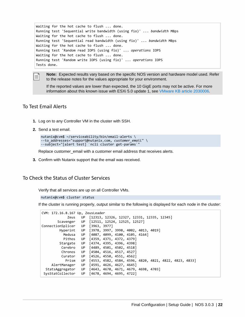
Waiting for the hot cache to flush ... done. Running test 'Sequential write bandwidth (using fio)' ... bandwidth MBps Waiting for the hot cache to flush ... done. Running test 'Sequential read bandwidth (using fio)' ... bandwidth MBps Waiting for the hot cache to flush ... done. Running test 'Random read IOPS (using fio)' ... operations IOPS Waiting for the hot cache to flush ... done. Running test 'Random write IOPS (using fio)' ... operations IOPS Tests done.
Note: Expected results vary based on the specific NOS version and hardware model used. Referto the release notes for the values appropriate for your environment.
If the reported values are lower than expected, the 10 GigE ports may not be active. For moreinformation about this known issue with ESXi 5.0 update 1, see VMware KB article 2030006.
To Test Email Alerts
1. Log on to any Controller VM in the cluster with SSH.
2. Send a test email.
nutanix@cvm$ ~/serviceability/bin/email-alerts \--to_addresses="[email protected], customer_email" \--subject="[alert test] `ncli cluster get-params`"
Replace customer_email with a customer email address that receives alerts.
3. Confirm with Nutanix support that the email was received.
To Check the Status of Cluster Services
Verify that all services are up on all Controller VMs.
nutanix@cvm$ cluster status
If the cluster is running properly, output similar to the following is displayed for each node in the cluster:
CVM: 172.16.8.167 Up, ZeusLeader Zeus UP [12313, 12326, 12327, 12331, 12335, 12345] Scavenger UP [12511, 12524, 12525, 12527]ConnectionSplicer UP [3963, 3977] Hyperint UP [3978, 3997, 3998, 4002, 4013, 4019] Medusa UP [4087, 4099, 4100, 4105, 4164] Pithos UP [4359, 4371, 4372, 4379] Stargate UP [4374, 4395, 4396, 4398] Cerebro UP [4489, 4501, 4502, 4518] Chronos UP [4504, 4516, 4517, 4527] Curator UP [4526, 4550, 4551, 4562] Prism UP [4553, 4582, 4584, 4596, 4820, 4821, 4822, 4823, 4833] AlertManager UP [4591, 4626, 4627, 4645] StatsAggregator UP [4643, 4670, 4671, 4679, 4698, 4703] SysStatCollector UP [4678, 4694, 4695, 4722]
Manual IP Address Configuration | Setup Guide | NOS 3.0.3 | 23
Appendix AManual IP Address Configuration
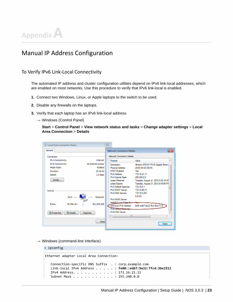
To Verify IPv6 Link-Local Connectivity
The automated IP address and cluster configuration utilities depend on IPv6 link-local addresses, whichare enabled on most networks. Use this procedure to verify that IPv6 link-local is enabled.
1. Connect two Windows, Linux, or Apple laptops to the switch to be used.
2. Disable any firewalls on the laptops.
3. Verify that each laptop has an IPv6 link-local address.
→ Windows (Control Panel)
Start > Control Panel > View network status and tasks > Change adapter settings > LocalArea Connection > Details
→ Windows (command-line interface)
> ipconfig
Ethernet adapter Local Area Connection:
Connection-specific DNS Suffix . : corp.example.com Link-local IPv6 Address . . . . . : fe80::ed67:9a32:7fc4:3be1%12 IPv4 Address. . . . . . . . . . . : 172.16.21.11 Subnet Mask . . . . . . . . . . . : 255.240.0.0
Manual IP Address Configuration | Setup Guide | NOS 3.0.3 | 24
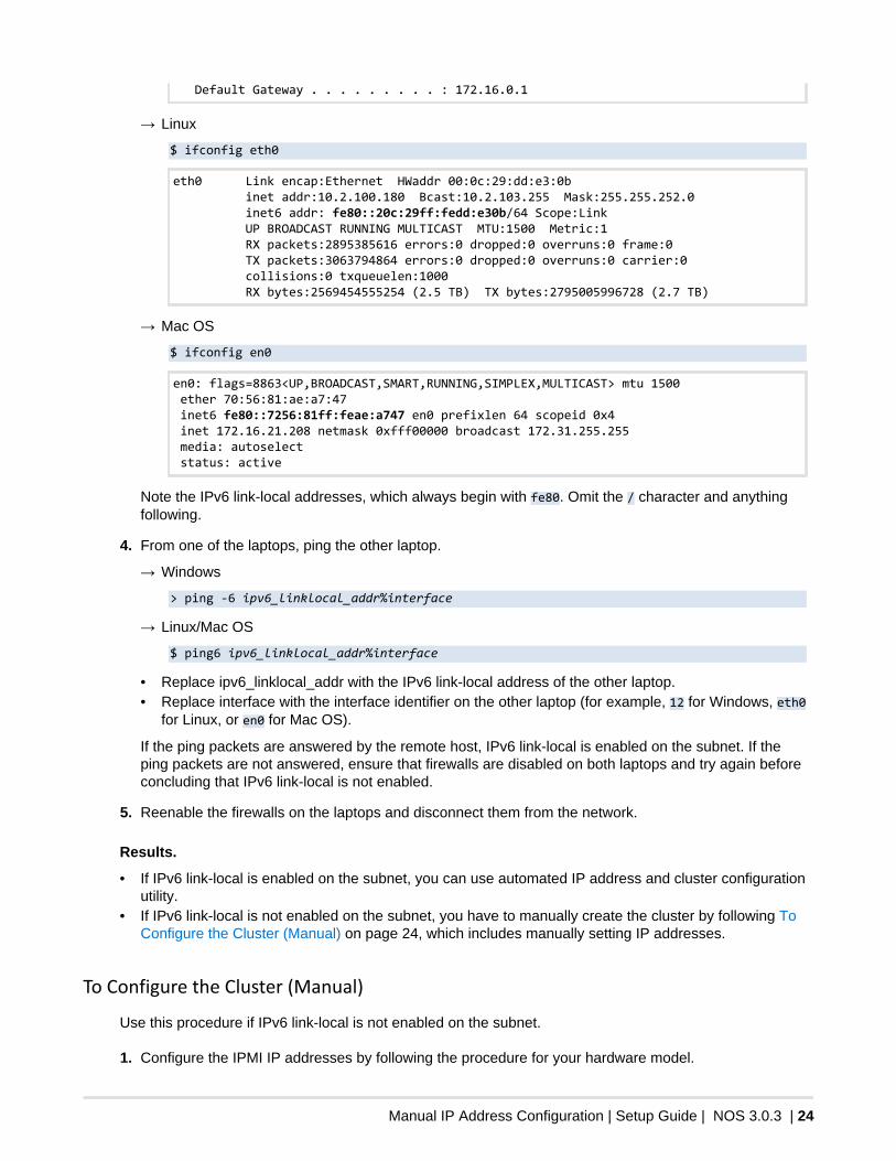
Default Gateway . . . . . . . . . : 172.16.0.1
→ Linux
$ ifconfig eth0
eth0 Link encap:Ethernet HWaddr 00:0c:29:dd:e3:0b inet addr:10.2.100.180 Bcast:10.2.103.255 Mask:255.255.252.0 inet6 addr: fe80::20c:29ff:fedd:e30b/64 Scope:Link UP BROADCAST RUNNING MULTICAST MTU:1500 Metric:1 RX packets:2895385616 errors:0 dropped:0 overruns:0 frame:0 TX packets:3063794864 errors:0 dropped:0 overruns:0 carrier:0 collisions:0 txqueuelen:1000 RX bytes:2569454555254 (2.5 TB) TX bytes:2795005996728 (2.7 TB)
→ Mac OS
$ ifconfig en0
en0: flags=8863<UP,BROADCAST,SMART,RUNNING,SIMPLEX,MULTICAST> mtu 1500 ether 70:56:81:ae:a7:47 inet6 fe80::7256:81ff:feae:a747 en0 prefixlen 64 scopeid 0x4 inet 172.16.21.208 netmask 0xfff00000 broadcast 172.31.255.255 media: autoselect status: active
Note the IPv6 link-local addresses, which always begin with fe80. Omit the / character and anythingfollowing.
4. From one of the laptops, ping the other laptop.
→ Windows
> ping -6 ipv6_linklocal_addr%interface
→ Linux/Mac OS
$ ping6 ipv6_linklocal_addr%interface
• Replace ipv6_linklocal_addr with the IPv6 link-local address of the other laptop.• Replace interface with the interface identifier on the other laptop (for example, 12 for Windows, eth0
for Linux, or en0 for Mac OS).
If the ping packets are answered by the remote host, IPv6 link-local is enabled on the subnet. If theping packets are not answered, ensure that firewalls are disabled on both laptops and try again beforeconcluding that IPv6 link-local is not enabled.
5. Reenable the firewalls on the laptops and disconnect them from the network.
Results.
• If IPv6 link-local is enabled on the subnet, you can use automated IP address and cluster configurationutility.
• If IPv6 link-local is not enabled on the subnet, you have to manually create the cluster by following ToConfigure the Cluster (Manual) on page 24, which includes manually setting IP addresses.
To Configure the Cluster (Manual)
Use this procedure if IPv6 link-local is not enabled on the subnet.
1. Configure the IPMI IP addresses by following the procedure for your hardware model.
Manual IP Address Configuration | Setup Guide | NOS 3.0.3 | 25
→ To Configure the Remote Console IP Address (NX-3050) on page 26→ To Configure the Remote Console IP Address (NX-3000) on page 27→ To Configure the Remote Console IP Address (NX-2000) on page 27
Alternatively, you can set the IPMI IP address using a command-line utility by following To Configurethe Remote Console IP Address (command line) on page 28.
2. Configure the ESXi host IP addresses by following To Configure a Host IP Address on page 29.
3. Configure the Controller VM IP addresses by following To Configure the Controller VM IP Address onpage 29.
4. Log on to any Controller VM in the cluster with SSH.
5. Create the cluster.
nutanix@cvm$ cluster -s cvm_ip_addrs create
Replace cvm_ip_addrs with a comma-separated list of Controller VM IP addresses. Include allController VMs that will be part of the cluster.
For example, if the new cluster should comprise all four nodes in a block, include all the IP addresses ofall four Controller VMs.
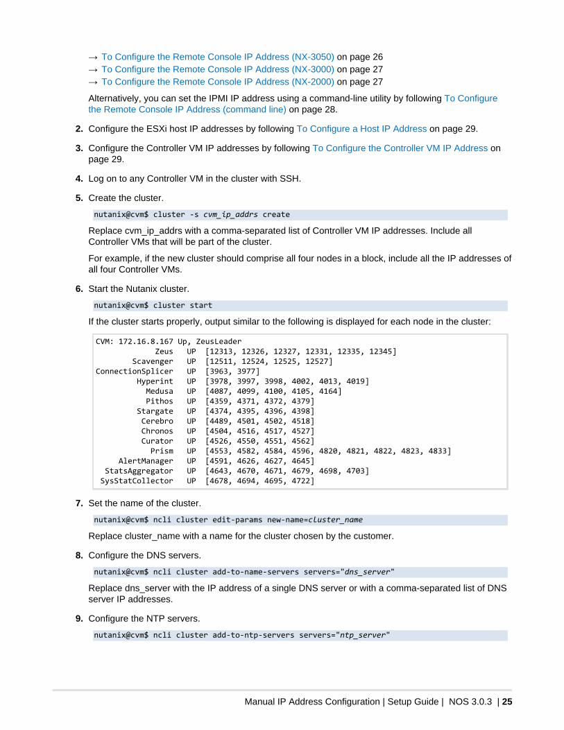
6. Start the Nutanix cluster.
nutanix@cvm$ cluster start
If the cluster starts properly, output similar to the following is displayed for each node in the cluster:
CVM: 172.16.8.167 Up, ZeusLeader Zeus UP [12313, 12326, 12327, 12331, 12335, 12345] Scavenger UP [12511, 12524, 12525, 12527]ConnectionSplicer UP [3963, 3977] Hyperint UP [3978, 3997, 3998, 4002, 4013, 4019] Medusa UP [4087, 4099, 4100, 4105, 4164] Pithos UP [4359, 4371, 4372, 4379] Stargate UP [4374, 4395, 4396, 4398] Cerebro UP [4489, 4501, 4502, 4518] Chronos UP [4504, 4516, 4517, 4527] Curator UP [4526, 4550, 4551, 4562] Prism UP [4553, 4582, 4584, 4596, 4820, 4821, 4822, 4823, 4833] AlertManager UP [4591, 4626, 4627, 4645] StatsAggregator UP [4643, 4670, 4671, 4679, 4698, 4703] SysStatCollector UP [4678, 4694, 4695, 4722]
7. Set the name of the cluster.
nutanix@cvm$ ncli cluster edit-params new-name=cluster_name
Replace cluster_name with a name for the cluster chosen by the customer.
8. Configure the DNS servers.
nutanix@cvm$ ncli cluster add-to-name-servers servers="dns_server"
Replace dns_server with the IP address of a single DNS server or with a comma-separated list of DNSserver IP addresses.
9. Configure the NTP servers.
nutanix@cvm$ ncli cluster add-to-ntp-servers servers="ntp_server"
Manual IP Address Configuration | Setup Guide | NOS 3.0.3 | 26
Replace ntp_server with the IP address or host name of a single NTP server or a with a comma-separated list of NTP server IP addresses or host names.
Remote Console IP Address Configuration
The Intelligent Platform Management Interface (IPMI) is a standardized interface used to manage a hostand monitor its operation. To enable remote access to the console of each host, you must configure theIPMI settings within BIOS.
The Nutanix cluster provides a Java application to remotely view the console of each node, or host server.You can use this console to configure additional IP addresses in the cluster.
The procedure for configuring the remote console IP address is slightly different for each hardwareplatform.
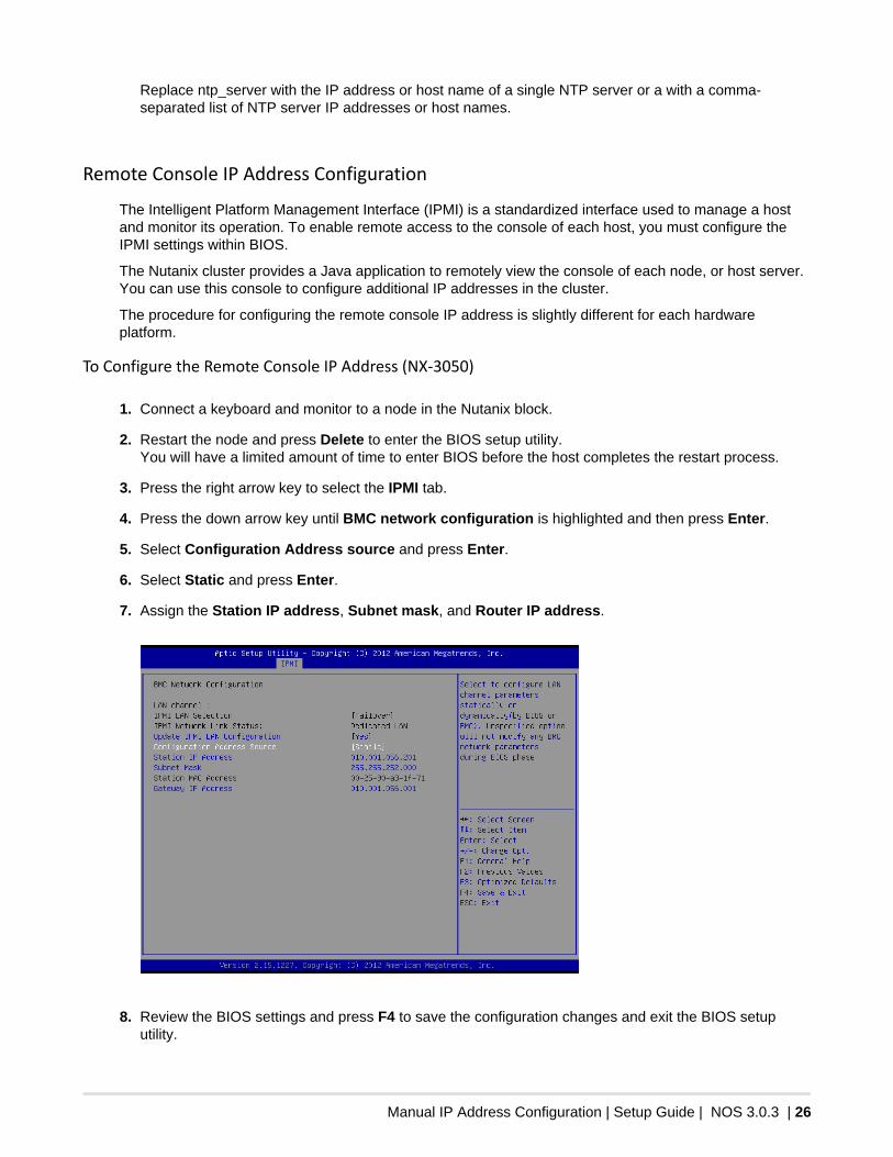
To Configure the Remote Console IP Address (NX-3050)
1. Connect a keyboard and monitor to a node in the Nutanix block.
2. Restart the node and press Delete to enter the BIOS setup utility.You will have a limited amount of time to enter BIOS before the host completes the restart process.
3. Press the right arrow key to select the IPMI tab.
4. Press the down arrow key until BMC network configuration is highlighted and then press Enter.
5. Select Configuration Address source and press Enter.
6. Select Static and press Enter.
7. Assign the Station IP address, Subnet mask, and Router IP address.
8. Review the BIOS settings and press F4 to save the configuration changes and exit the BIOS setuputility.
Manual IP Address Configuration | Setup Guide | NOS 3.0.3 | 27
The node restarts.
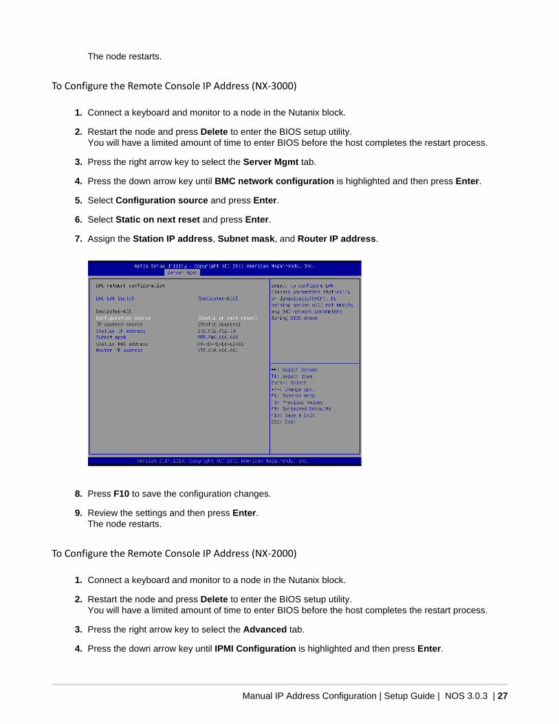
To Configure the Remote Console IP Address (NX-3000)
1. Connect a keyboard and monitor to a node in the Nutanix block.
2. Restart the node and press Delete to enter the BIOS setup utility.You will have a limited amount of time to enter BIOS before the host completes the restart process.
3. Press the right arrow key to select the Server Mgmt tab.
4. Press the down arrow key until BMC network configuration is highlighted and then press Enter.
5. Select Configuration source and press Enter.
6. Select Static on next reset and press Enter.
7. Assign the Station IP address, Subnet mask, and Router IP address.
8. Press F10 to save the configuration changes.
9. Review the settings and then press Enter.The node restarts.
To Configure the Remote Console IP Address (NX-2000)
1. Connect a keyboard and monitor to a node in the Nutanix block.
2. Restart the node and press Delete to enter the BIOS setup utility.You will have a limited amount of time to enter BIOS before the host completes the restart process.
3. Press the right arrow key to select the Advanced tab.
4. Press the down arrow key until IPMI Configuration is highlighted and then press Enter.
Manual IP Address Configuration | Setup Guide | NOS 3.0.3 | 28
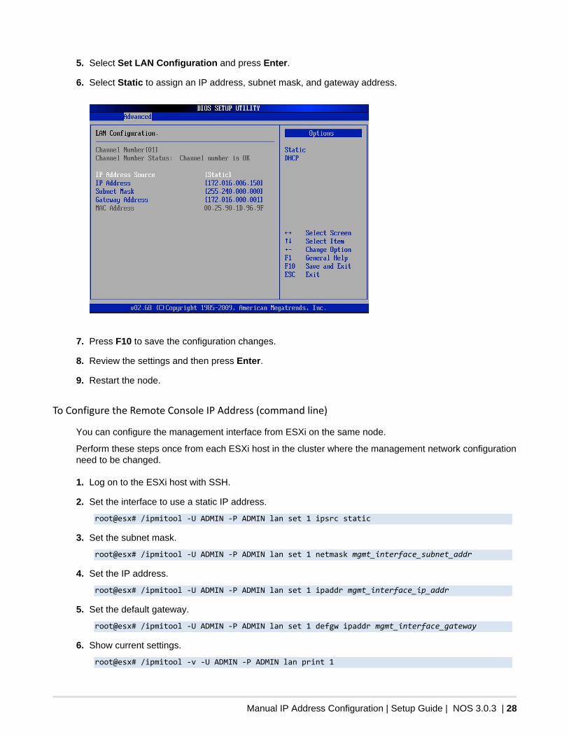
5. Select Set LAN Configuration and press Enter.
6. Select Static to assign an IP address, subnet mask, and gateway address.
7. Press F10 to save the configuration changes.
8. Review the settings and then press Enter.
9. Restart the node.
To Configure the Remote Console IP Address (command line)
You can configure the management interface from ESXi on the same node.
Perform these steps once from each ESXi host in the cluster where the management network configurationneed to be changed.
1. Log on to the ESXi host with SSH.
2. Set the interface to use a static IP address.
root@esx# /ipmitool -U ADMIN -P ADMIN lan set 1 ipsrc static
3. Set the subnet mask.
root@esx# /ipmitool -U ADMIN -P ADMIN lan set 1 netmask mgmt_interface_subnet_addr
4. Set the IP address.
root@esx# /ipmitool -U ADMIN -P ADMIN lan set 1 ipaddr mgmt_interface_ip_addr
5. Set the default gateway.
root@esx# /ipmitool -U ADMIN -P ADMIN lan set 1 defgw ipaddr mgmt_interface_gateway
6. Show current settings.
root@esx# /ipmitool -v -U ADMIN -P ADMIN lan print 1
Manual IP Address Configuration | Setup Guide | NOS 3.0.3 | 29
Confirm that the parameters are set to the correct values.
To Configure a Host IP Address
You can access the ESXi console either through IPMI or by attaching a keyboard and monitor to the node.
1. On the ESXi host console, press F2 and then provide the ESXi host logon credentials.
2. Press the down arrow key until Configure Management Network is highlighted and then press Enter.
3. Select IP Configuration and press Enter.
4. If necessary, highlight the Set static IP address and network configuration option and press Spaceto update the setting.
5. Provide values for the following: IP Address, Subnet Mask, and Default Gateway fields based on yourenvironment and then press Enter .
6. Select DNS Configuration and press Enter.
7. If necessary, highlight the Use the following DNS server addresses and hostname option and pressSpace to update the setting.
8. Provide values for the Primary DNS Server and Alternate DNS Server fields based on yourenvironment and then press Enter.
9. Press Esc and then Y to apply all changes and restart the management network.
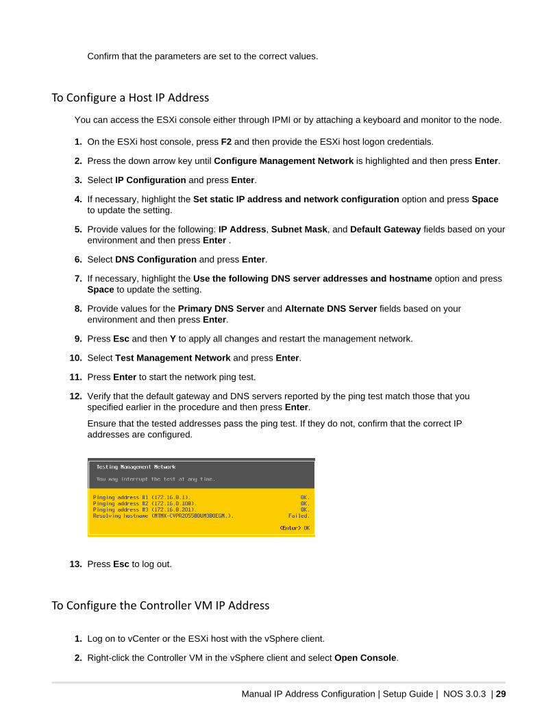
10. Select Test Management Network and press Enter.
11. Press Enter to start the network ping test.
12. Verify that the default gateway and DNS servers reported by the ping test match those that youspecified earlier in the procedure and then press Enter.
Ensure that the tested addresses pass the ping test. If they do not, confirm that the correct IPaddresses are configured.
13. Press Esc to log out.
To Configure the Controller VM IP Address
1. Log on to vCenter or the ESXi host with the vSphere client.
2. Right-click the Controller VM in the vSphere client and select Open Console.
Manual IP Address Configuration | Setup Guide | NOS 3.0.3 | 30
If the logon screen does not appear in the vSphere client Console window, click inside the window andpress Alt+F2.
3. Enter the username and password.
4. Change the network interface configuration.
a. Open the network interface configuration file.
nutanix@cvm$ sudo vi /etc/sysconfig/network-scripts/ifcfg-eth0
Enter the nutanix password.
b. Press A to edit values in the file.
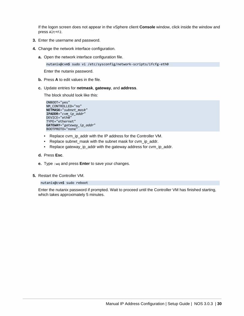
c. Update entries for netmask, gateway, and address.
The block should look like this:
ONBOOT="yes" NM_CONTROLLED="no" NETMASK="subnet_mask" IPADDR="cvm_ip_addr" DEVICE="eth0" TYPE="ethernet" GATEWAY="gateway_ip_addr" BOOTPROTO="none"
• Replace cvm_ip_addr with the IP address for the Controller VM.• Replace subnet_mask with the subnet mask for cvm_ip_addr.• Replace gateway_ip_addr with the gateway address for cvm_ip_addr.
d. Press Esc.
e. Type :wq and press Enter to save your changes.
5. Restart the Controller VM.
nutanix@cvm$ sudo reboot
Enter the nutanix password if prompted. Wait to proceed until the Controller VM has finished starting,which takes approximately 5 minutes.