Embed Size (px)
Citation preview

Master Thesis Erasmus Mundus Master of Mechanical Engineering
Setup of the Manufacturing Process and Economic Study of the Gear Box for Industrial Vehicle
Report
Author: Sarawut WONGTHIANCHAI Adviser: IRENE BUJ CORRAL
Escola Tècnica Superior d’Enginyeria Industrial de Barcelona

Page 1
Acknowledgments No any accomplishment of any significance is achieved solely by the effort of one person and that is certainly true of this project. I am deeply indebted to Prof. Irene Buj Corral, my advisor, who has been a true mentor and guide, and to the member of my project committee, Prof. Joan Vivancos Calvet for the assistance he has provided. I am also indebted to Prof. Ana Barjau Condomines and Prof. Jean- Claude BOYER ( INSA DE LYON ) as well as the European Commission who have provided me the greatest opportunity of my life, the chance to study master degree in INSA DE LYON and ETSEIB, UPC. I would like to thanks every professors in INSA DE LYON and ETSEIB for the everything you gave me during these 2 years. Thank you to my Erasmus Mundus colleague for the friendship and pleasure. Finally, I must acknowledge my fiancée for without her love, patience, encouragement and support, this project would never have been completed. To all, a sincere thank you Sarawut WONGTHIANCHAI

Page 2
Table of Contents Page
Acknowledgments…………………………………………………………... 1
List of Figures………………………………………………………………. 6
List of Tables……………………………………………………………….. 9
Abstract……………………………………………………………………... 12
Introduction of the Project……………………………………………..…... 13
Objectives of the Project ………………………………………………….... 14
Gear Box Overview…...….…………………………………………………. 15
1. Marketing study………………………………………………………….. 16 1.1. Introduction……………………………………………………… 16
1.2. Objective………………………………………………………… 16 1.3. Estimation Method………………………………………………. 16 1.4. Assumptions……………………………………………………... 17 1.5. Estimation For Year 2008, main targets are in Spain……………. 17
1.6. Estimation For Year 2009 - 2012, main targets are expanded to Europe…………………………………………………………. 18 1.7. Conclusion………………………………………………………. 20
2. Manufacturing Process of Shaft 1………………………………………... 21 2.1. The Raw Material……………………………………………….. 21 2.2. The Process and Calculation of Phase10………………………... 21 2.3. The Process and Calculation of Phase20………………………... 21 2.4. The Process and Calculation of Phase30………………………... 25 2.5. The Process and Calculation of Phase40………………………... 26 2.6. The Process and Calculation of Phase50………………………... 30 2.7. The Process and Calculation of Phase60………………………... 33 2.8. The Process and Calculation of Phase70………………………... 35 2.9. The Process and Calculation of Phase80………………………... 36 2.10. The Process and Calculation of Phase90………………………. 36 2.11. The Process and Calculation of Phase100……………………... 36 2.12. Calculation of Cycle Time for Shaft1………………………….. 39
3. Manufacturing Process of Shaft 2………………………………………... 43 3.1. The Raw Material……………………………………………….. 43 3.2. The Process and Calculation of Phase10………………………... 43 3.3. The Process and Calculation of Phase20………………………... 43 3.4. The Process and Calculation of Phase30………………………... 46 3.5. The Process and Calculation of Phase40………………………... 47 3.6. The Process and Calculation of Phase50………………………... 50

Page 3
Page
3.7. The Process and Calculation of Phase60………………………... 51 3.8. The Process and Calculation of Phase70………………………... 53 3.9. The Process and Calculation of Phase80………………………... 54 3.10. The Process and Calculation of Phase90………………………. 54 3.11. The Process and Calculation of Phase100……………………... 54 3.12. Calculation of Cycle Time for Shaft1………………………….. 56
4. Manufacturing Process of Casing………………………………………... 58 4.1. The Raw Material……………………………………………….. 58 4.2. The Process and Calculation of Phase20………………………... 58 4.3. The Process and Calculation of Phase30………………………... 62 4.4. The Process and Calculation of Phase40………………………... 65 4.5. Calculation of Cycle Time for Casing…………………………... 69
5. Manufacturing Process of Sliding part…………………………………… 70 5.1. The Raw Material………………………………………………... 70 5.2. The Process and Calculation of Phase10………………………... 70 5.3. The Process and Calculation of Phase20………………………… 71 5.4. The Process and Calculation of Phase30……………………….... 73 5.5. Calculation of Cycle Time for Sliding part………………………. 74
6. Manufacturing Process of Clutch Fork……………………………………. 75 6.1. The Raw Material………………………………………………... 75 6.2. The Process and Calculation of Phase20………………………… 75 6.3. The Process and Calculation of Phase30………………………… 77 6.4. The Process and Calculation of Phase40………………………… 78 6.5. The Process and Calculation of Phase50………………………… 79 6.6. Calculation of Cycle Time for Clutch Fork……………………… 79
7. Manufacturing Process of Pin……………………………………………... 80 7.1. The Raw Material……………………………………………….... 80 7.2. The Process and Calculation of Phase10…………………………. 80 7.3. The Process and Calculation of Phase20…………………………. 80 7.4. The Process and Calculation of Phase30…………………………. 82 7.5. The Process and Calculation of Phase40…………………………. 83 7.6. The Process and Calculation of Phase50…………………………. 85 7.7. Calculation of Cycle Time for Pin………………………………... 85
8. Manufacturing Process of Sealing plate 1-2.................................................. 86 8.1. The Raw Material…………………………………………………. 86 8.2. The Process and Calculation of Phase10………………………….. 86 8.3. The Process and Calculation of Phase20………………………….. 89 8.4. Calculation of Cycle Time for Sealing plate 1-2………………….. 93
9. Manufacturing Process of Transmission Plate 2……………………………. 94 9.1. The Raw Material………………………………………………….. 94 9.2. The Process and Calculation of Phase20………………………….. 94 9.3. The Process and Calculation of Phase30…………………………... 96

Page 4
Page
9.4. The Process and Calculation of Phase40…………………………... 98 9.5. The Process and Calculation of Phase50…………………………... 99 9.6. The Process and Calculation of Phase60…………………………... 102
9.7. Calculation of Cycle Time for Transmission Plate 2………………. 103
10. Manufacturing Process of Washer 2………………………………………. 104 10.1. The Raw Material………………………………………………... 104 10.2. The Process and Calculation of Phase10………………………… 104 10.3. The Process and Calculation of Phase20………………………… 104 10.4. Calculation of Cycle Time for Washer 2………………………… 108 11. Manufacturing Process of Gear1………………………………………….. 109 11.1. The Raw Material………………………………………………... 109 11.2. The Process and Calculation of Phase20………………………… 109 11.3. The Process and Calculation of Phase30………………………… 111 11.4. The Process and Calculation of Phase40………………………… 113 11.5. The Process and Calculation of Phase50………………………… 113 11.6. The Process and Calculation of Phase60………………………… 115 11.7. Calculation of Cycle Time for Gear1……………………………. 116
12. Manufacturing Process of Gear2………………………………………….. 117 12.1. The Raw Material………………………………………………... 117 12.2. The Process and Calculation of Phase20………………………… 117 12.3. The Process and Calculation of Phase30………………………… 119 12.4. The Process and Calculation of Phase40………………………… 121 12.5. The Process and Calculation of Phase50………………………… 121 12.6. The Process and Calculation of Phase60………………………… 122 12.7. Calculation of Cycle Time for Gear2……………………………. 123
13. Choosing the proper machine....................................................................... 124 13.1. CNC Lathe Machine…………………………………………….. 124 13.2. CNC Milling Machine…………………………………………... 125 13.3. Manual Grinding Machine……………………………………… 128 13.4. Broaching Machine……………………………………………… 129 13.5. Hobbing Machine……………………………………………….. 130 13.6. Manual Disc Saw Machine……………………………………… 132 13.7. Manual Sensitive Press………………………………………….. 133
14. Calculation of the Machines Amount Required…………………………… 134
15. Calculation of the Workers Amount Required……………………………. 135
16. Economic Study…………………………………………………………… 137 16.1. The calculation of Hour Cost……………………………………. 137 16.2. The calculation of The Price of the cost of the Product…………. 140 16.3. The calculation of Inversion Cost……………………………….. 142 16.4. The calculation of the Selling Price of the Product……………… 142 16.5. The Situation of the Company in the Next 5 years……………… 143 16.6. The calculation of Cash Flow…………………………………… 144
Page 5
Page
16.7. The calculation of the Period of Pay Back………………………. 144 16.8. The calculation of “ Net Present Value “ (NPV)………………. 145
16.9. The calculation of “ Internal Rate of Return “ (IRR)…………… 146
17. Production Plant Layout and the Company’s Location…………………… 147 17.1. Production Plant Layout…………………………………………. 147 17.2. The Company’s Location………………………………………... 148
18. Waste Management and Security Policy for Workers………..................... 151 18.1. Waste Management……………………………………………… 151 18.2. The Security Policy for Workers………………………………… 153
19. Conclusions……………………………………………………………….. 154
References……………………………………………………………………... 155
Page 6
List of Figures Figure Page
2.1 Operation of Phase10 of Shaft1……………………………... 21 2.2 Operation of Phase20 Step1 of Shaft1…………………….... 22 2.3 Operation of Phase20 Step2 of Shaft1……………………… 24 2.4 Operation of Phase30 Step1 of Shaft1……………………… 25 2.5 Operation of Phase30 Step2 of Shaft1……………………… 26
2.6 Operation of Phase40 Step1 of Shaft1……………………… 26 2.7 Operation of Phase40 Step2 of Shaft1……………………… 27 2.8 Operation of Phase40 Step3 of Shaft1……………………… 28 2.9 Operation of Phase40 Step4 of Shaft1……………………… 29 2.10 Operation of Phase40 Step5 of Shaft1……………………… 29 2.11 Operation of Phase50 Step1 of Shaft1……………………… 30 2.12 Operation of Phase60 Step1 of Shaft1……………………… 33 2.13 Operation of Phase60 Step2 of Shaft1……………………… 34 2.14 Operation of Phase60 Step3 of Shaft1……………………… 35 2.15 Operation of Phase70 of Shaft1…………………………….. 36 2.16 Operation of Phase90 of Shaft1…………………………….. 36 2.17 Operation of Phase100 Step1 of Shaft1……………………... 37 2.18 Operation of Phase100 Step2 of Shaft1…………………….. 39 3.1 Operation of Phase10 of Shaft2…………………………….. 43 3.2 Operation of Phase20 Step1 of Shaft2……………………… 44 3.3 Operation of Phase20 Step2 of Shaft2……………………… 44 3.4 Operation of Phase20 Step3 of Shaft2……………………… 45 3.5 Operation of Phase20 Step4 of Shaft2……………………… 45 3.6 Operation of Phase30 Step1 of Shaft2……………………… 46 3.7 Operation of Phase30 Step2 of Shaft2……………………… 46 3.8 Operation of Phase40 Step1 of Shaft2……………………… 47 3.9 Operation of Phase40 Step2 of Shaft2……………………… 48 3.10 Operation of Phase40 Step3 of Shaft2……………………… 49 3.11 Operation of Phase40 Step4 of Shaft2……………………… 50 3.12 Operation of Phase50 Step1 of Shaft2……………………… 51 3.13 Operation of Phase60 Step1 of Shaft2………………………. 52 3.14 Operation of Phase60 Step2 of Shaft2……………………… 52 3.15 Operation of Phase70 Step1 of Shaft2………………………. 53 3.16 Operation of Phase70 Step2 of Shaft2……………………… 53 3.17 Operation of Phase90 of Shaft2……………………………... 54 3.18 Operation of Phase100 Step1 of Shaft2…………………….. 55 3.19 Operation of Phase100 Step2 of Shaft2…………………….. 55 4.1 Operation of Phase20 Step1 of Casing……………………… 58 4.2 Operation of Phase20 Step2 of Casing…………………….... 59 4.3 Operation of Phase20 Step3 of Casing……………………… 60 4.4 Operation of Phase20 Step4 of Casing……………………… 60 4.5 Operation of Phase20 Step5 of Casing……………………… 61 4.6 Operation of Phase30 Step1 of Casing……………………… 62
4.7 Drawing for tool’s movement path calculation of Phase30 Step1 of Casing……………………………………. 63 4.8 Operation of Phase30 Step2 of Casing……………………… 63

Page 7
Figure Page
4.9 Operation of Phase30 Step3 of Casing…………………… 64 4.10 Operation of Phase40 Step1 of Casing…………………… 65 4.11 Operation of Phase40 Step2 of Casing…………………… 66 4.12 Operation of Phase40 Step3 of Casing…………………… 66
4.13 Operation of Phase40 Step4 of Casing…………………… 67 4.14 Operation of Phase40 Step5 of Casing…………………… 67 5.1 Operation of Phase10 of Sliding part……………………... 70 5.2 Operation of Phase20 Step1 of Sliding part…..................... 71 5.3 Operation of Phase20 Step2 of Sliding part…..................... 72 5.4 Operation of Phase30 Step1 of Sliding part…..................... 73 6.1 Operation of Phase20 Step1 of Clutch Fork……………..... 75 6.2 Operation of Phase20 Step2 of Clutch Fork………………. 76 6.3 Operation of Phase20 Step3 of Clutch Fork………………. 76 6.4 Operation of Phase30 Step1 of Clutch Fork………………. 77 6.5 Operation of Phase30 Step1 of Clutch Fork………………. 78 7.1 Operation of Phase10 of Pin……………………………….. 80 7.2 Operation of Phase20 Step1 of Pin………………………… 81 7.3 Operation of Phase20 Step2 of Pin………………………… 81 7.4 Operation of Phase30 Step1 of Pin………………………… 82 7.5 Operation of Phase30 Step2 of Pin………………………… 83 7.6 Operation of Phase40 Step1 of Pin………………………… 84 7.7 Operation of Phase40 Step2 of Pin………………………… 84 8.1 Operation of Phase10 Step1 of Sealing plate 1-2………….. 86 8.2 Operation of Phase10 Step2 of Sealing plate 1-2………….. 87 8.3 Operation of Phase10 Step3 of Sealing plate 1-2………….. 87 8.4 Operation of Phase10 Step4 of Sealing plate 1-2………….. 88 8.5 Operation of Phase20 Step1 of Sealing plate 1-2………….. 89 8.6 Operation of Phase20 Step2 of Sealing plate 1-2………….. 90 8.7 Operation of Phase20 Step3 of Sealing plate 1-2………….. 90
8.8 Drawing for cutting volume calculation of Phase20 Step3 of Sealing plate 1-2………………………………………… 91
8.9 Operation of Phase20 Step4 of Sealing plate 1-2………….. 91 9.1 Operation of Phase20 Step1 of Transmission Plate 2……… 94 9.2 Operation of Phase20 Step2 of Transmission Plate 2……… 95 9.3 Operation of Phase20 Step3 of Transmission Plate 2……… 95 9.4 Operation of Phase30 Step1 of Transmission Plate 2……… 96 9.5 Operation of Phase30 Step2 of Transmission Plate 2……… 97 9.6 Operation of Phase30 Step3 of Transmission Plate 2……… 97 9.7 Operation of Phase40 Step1 of Transmission Plate 2……… 98 9.8 Operation of Phase50 Step1 of Transmission Plate 2……… 99 9.9 The cutting surface of part in Broaching Process………….. 101 10.1 Operation of Phase10 of Washer2…………………………. 104 10.2 Operation of Phase20 Step1 of Washer2…………………... 105 10.3 Operation of Phase20 Step2 of Washer2…………………... 105 10.4 Operation of Phase20 Step3 of Washer2…………………... 106 10.5 Operation of Phase20 Step4 of Washer2…………………... 106 10.6 Operation of Phase20 Step5 of Washer2…………………... 107 11.1 Operation of Phase20 Step1 of Gear1……………………... 109

Page 8
Figure Page
11.2 Operation of Phase20 Step2 of Gear1……………………... 110 11.3 Operation of Phase20 Step3 of Gear1……………………... 110 11.4 Operation of Phase30 Step1 of Gear1……………………... 111 11.5 Operation of Phase30 Step2 of Gear1……………………... 112 11.6 Operation of Phase40 Step1 of Gear1……………………... 113 12.1 Operation of Phase20 Step1 of Gear2……………………... 117 12.2 Operation of Phase20 Step2 of Gear2……………………... 118 12.3 Operation of Phase20 Step3 of Gear2……………………... 118 12.4 Operation of Phase30 Step1 of Gear2……………………... 119 12.5 Operation of Phase30 Step2 of Gear2……………………... 120 12.6 Operation of Phase40 Step1 of Gear2……………………... 121 13.1 CNC Lathe Machine Model: SL-10HE……………………. 124
13.2 CNC Milling Machine Model: CNC Supra Vertical Knee-Type…………………………………………………. 126 13.3 8” CNC Rotary Table……………………………………… 127 13.4 Manual Grinding Machine Model: PMT/300/125………… 128 13.5 Broaching Machine Model: Slotting CNC-200S…………. 130 13.6 Hobbing Machine Model: LC-200………………………... 131 13.7 Manual Disc Saw Machine Model: YY-131-004…………. 132
13.8 Manual Sensitive Press Machine Model: 10 T……………. 133 16.1 Diagram of the Period of Pay Back……………………….. 145 17.1 Plant Layout……………………………………………….. 148 17.2 Map of Spain………………………………………………. 149 17.3 Map of Barcelona…………………………………………. 149 17.4 El Prat de Llobregat Industrial Area, Barcelona…………... 150
17.5 Vila de Begur Street in el Prat de Llobregat Area…………. 150
Page 9
List of Tables Table Page 1.1 Number of company in Spain………………………………... 17 1.2 Number of Company in 4 European Country, year 2004……. 19 1.3 Total expected production from year 2008-2012……………. 20 2.1 Calculation data of Phase10 of Shaft1...................................... 21
2.2 Class of surface rugosity……………………………………... 23 2.3 Calculation data of Phase20 of Shaft1……………………….. 25 2.4 Calculation data of Phase30 of Shaft1……………………….. 26 2.5 Calculation data of Phase40 of Shaft1……………………….. 30 2.6 Tool size data for gear shape tool……………………………. 32 2.7 Number of tool data for gear shape tool……………………... 32 2.8 Cutting speed and advance of teeth for different materials….. 33 2.9 Calculation data of Phase50 of Shaft1……………………….. 33 2.10 Data of external groove at section A-A of Shaft1……………. 34 2.11 Calculation data of Phase60 of Shaft1……………………….. 35 2.12 Cutting speed (Vc) for grinding process……………………... 37 2.13 Calculation data of Phase100 of Shaft1……………………… 39 2.14 Cycle Time for Shaft1………………………………………... 41 2.15 Proper Cutting Speed………………………………………… 42 3.1 Calculation data of Phase10 of Shaft2……………………….. 43 3.2 Calculation data of Phase20 of Shaft2……………………….. 46 3.3 Calculation data of Phase30 of Shaft2……………………….. 47 3.4 Calculation data of Phase40 of Shaft2……………………….. 50 3.5 Calculation data of Phase50 of Shaft2……………………….. 51 3.6 Calculation data of Phase60 of Shaft2……………………….. 53 3.7 Calculation data of Phase100 of Shaft2……………………… 56 3.8 Cycle Time for Shaft2……………………………………….. 56 4.1 Calculation data of Phase20 of Casing………………………. 62 4.2 Calculation data of Phase30 of Casing………………………. 64 4.3 Calculation data of Phase40 of Casing………………………. 68 4.4 Cycle Time for Casing……………………………………….. 69 5.1 Calculation Data of Phase10 of Sliding part............................. 70 5.2 Calculation Data of Phase20 of Sliding part............................. 73 5.3 Calculation Data of Phase30 of Sliding part............................. 74 5.4 Cycle Time for Sliding part...................................................... 74 6.1 Calculation data of Phase20 of Clutch Fork…………………. 77 6.2 Calculation data of Phase30 of Clutch Fork…………………. 78 6.3 Calculation data of Phase40 of Clutch Fork…………………. 79 6.4 Cycle Time for Clutch Fork…………………………………. 79 7.1 Calculation data of Phase10 of Pin…………………………... 80 7.2 Calculation data of Phase20 of Pin…………………………... 82 7.3 Calculation data of Phase30 of Pin…………………………... 83 7.4 Calculation data of Phase40 of Pin…………………………... 84 7.5 Cycle Time for Pin…………………………………………… 85
8.1 Calculation data of Phase10 of Sealing plate1-2…………….. 88 8.2 Calculation data of Phase20 of Sealing plate1-2…………….. 92 8.3 Cycle time for Sealing plate1-2……………………………… 93

Page 10
Table Page 9.1 Calculation data of Phase20 of Transmission Plate2………… 96 9.2 Calculation data of Phase30 of Transmission Plate2………… 98 9.3 Calculation data of Phase40 of Transmission Plate2………… 99 9.4 Calculation data of Phase50 of Transmission Plate2………… 102 9.5 Cycle time for Transmission Plate2………………………….. 103 10.1 Calculation data of Phase10 of Washer2…………………….. 104 10.2 Calculation data of Phase20 of Washer2…………………….. 107 10.3 Cycle time for Washer2……………………………………… 108 11.1 Calculation data of Phase20 of Gear1……………………….. 111 11.2 Calculation data of Phase30 of Gear1……………………….. 112 11.3 Calculation data of Phase40 of Gear1……………………….. 113 11.4 Data for external gear of Gear1……………………………… 114 11.5 Calculation data of Phase50 of Gear1……………………….. 115 11.6 Cycle time for Gear1………………………………………… 116 12.1 Calculation data of Phase20…………………………………. 119 12.2 Calculation data of Phase30…………………………………. 120 12.3 Calculation data of Phase40…………………………………. 121 12.4 Data for external gear of Gear1……………………………... 122 12.5 Calculation data of Phase50…………………………………. 122 12.6 Cycle time for Gear2………………………………………... 123 13.1 The Maximum machine power and rotation speed of turning operation…………………………………………….. 124 13.2 The Maximum machine power and rotation speed of milling operation…………………………………………….. 125
13.3 The Maximum machine power and rotation speed of grinding operation…………………………………………… 128 13.4 The Maximum machine power of broaching operation…….. 129 13.5 The Maximum machine power of gear machining operation 130 13.6 The Maximum machine power of saw operation…………... 132 14.1 The amount of Machines……………………………………. 134 15.1 The amount of workers ( Operator of Machine )…………... 136
15.2 The amount of workers and salary rate for all positions……. 136 16.1 The Amortization Cost……………………………………… 137 16.2 Show the details of investment cost of each machines and its amount…………………………………………………… 138 16.3 Total Electric Power Cost per Year………………………… 138 16.4 The Constants to be used in equation54……………………. 139 16.5 Total Salary Cost per year………………………………….. 139 16.6 Total General Cost………………………………………….. 139 16.7 Hour Cost…………………………………………………… 140 16.8 Steel Price…………………………………………………… 141 16.9 Raw Material Cost for each part……………………………. 141 16.10 The Price of the Cost of the Product………………………... 142 16.11 Inversion Cost for the first 3 months……………………….. 142 16.12 The Selling Price of the Product……………………………. 143 16.13 The Situation of the Company in the Next 5 years…………. 143 16.14 Cash Flow…………………………………………………… 144 16.15 The Period of Pay Back…………………………………….. 144

Page 11
Table Page 16.16 The results of the calculation of NPV……………………… 145 16.17 The calculation of IRR……………………………………… 146 17.1 The estimation of the required area for production plant…... 147 18.1 The list of the waste management company in Spain and
Europe………………………………………………………. 151

Page 12
Abstract The concept of the project is to setup the manufacturing process and the economic study as well as the production plant layout and waste management of the gear box for industrial vehicle. The gear box contains 21 main parts and 11 parts will be explained in this project, including: Shaft1, Shaft2, Casing, Sliding part, Clutch fork, Pin, Sealing plate1-2, Transmission Plate2, Washer2, Gear1 and Gear2. Firstly we have to do the marketing study in order to estimate the amount of the production we expect to sell in the first and the following years. The marketing study is done by analyzing the data from Spain and European database in industrial section together with the assumption based on reality. The results from this part are the expected production per year which can let us make the decision for the machine type and it will be used in economic study as well. Then the proper manufacturing process and specific tool’s type for each part will be decided and written on the Phase Document and the Summary of the Operation. These 2 documents are in the form that suitable to be used in reality effectively. Not only the manufacturing procedure, we also indicate the proper cutting condition and the calculations of cycle time, cutting force, machine power and the quality verification for each part. The data obtained by the calculation will be used to choose the specific model of machines, the amounts of machines and workers required to achieve the expected production. After we have the clear image of the production line, we shall advance to the economic study. The economic study is a good and reliable tool to indicate the profitability of the business. Every possible cost of the company will be taken into account and be presented as “ Hour Cost “. As well as the economic indicators such as Cash Flow, Period of Pay back, Net Present Value ( NPV ) and Internal Rate of Return ( IRR ) will be presented to be sure that the investment of this business will be profitable. The final tasks are the production plant layout and the waste management. The production plant layout will be designed sketchily as well as the specific suitable location. The waste management is the explanation the way to deal with the chips and chemical waste to be responsible for the social and environment.
Page 13
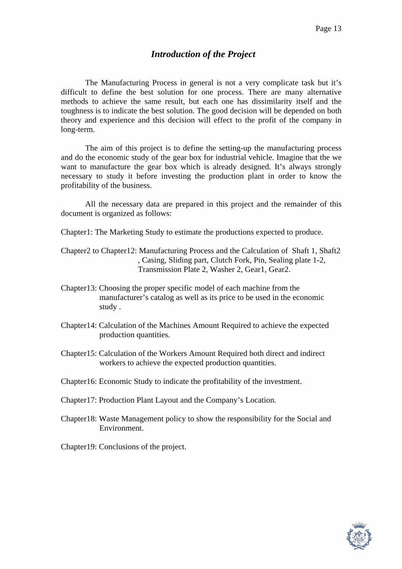
Introduction of the Project The Manufacturing Process in general is not a very complicate task but it’s difficult to define the best solution for one process. There are many alternative methods to achieve the same result, but each one has dissimilarity itself and the toughness is to indicate the best solution. The good decision will be depended on both theory and experience and this decision will effect to the profit of the company in long-term. The aim of this project is to define the setting-up the manufacturing process and do the economic study of the gear box for industrial vehicle. Imagine that the we want to manufacture the gear box which is already designed. It’s always strongly necessary to study it before investing the production plant in order to know the profitability of the business. All the necessary data are prepared in this project and the remainder of this document is organized as follows: Chapter1: The Marketing Study to estimate the productions expected to produce. Chapter2 to Chapter12: Manufacturing Process and the Calculation of Shaft 1, Shaft2 , Casing, Sliding part, Clutch Fork, Pin, Sealing plate 1-2, Transmission Plate 2, Washer 2, Gear1, Gear2. Chapter13: Choosing the proper specific model of each machine from the manufacturer’s catalog as well as its price to be used in the economic study . Chapter14: Calculation of the Machines Amount Required to achieve the expected production quantities. Chapter15: Calculation of the Workers Amount Required both direct and indirect workers to achieve the expected production quantities. Chapter16: Economic Study to indicate the profitability of the investment. Chapter17: Production Plant Layout and the Company’s Location. Chapter18: Waste Management policy to show the responsibility for the Social and Environment. Chapter19: Conclusions of the project.

Page 14
Objectives of the Project The main idea of this project is to be a tool for making the right decision to invest in manufacturing of the gear box for industrial vehicle as well as to prepare the manufacturing process for each part to be able to use in reality. At the end of the project, we expect to have the entire of important task to set-up the manufacturing process and the key point to indicate the profitable of this business. The objectives of the project are defined as follows:
- To define the operations as well as the quality verifications that are necessary to manufacture a number of gear boxes per year according to the marketing study.
- To prepare the Documents: Phase of Manufacturing Cycle which will be composed of the clearly process explanation, drawings for each step with the verification points, raw material details, specific tool’s type and measuring tool.
- To prepare the Documents: Summary of Operations which will be composed of the brief process explanation of every phase for each part.
- To select the specific type of machines according to the data from calculation part.
- To calculate the number of machines and direct workers according to the cycle time obtained in the calculation part.
- To carry out the economic study of the project to indicate the its profitability by obtaining these indicators: Hour Cost, Price of the cost of the product, Inversion Cost, Selling Price of the product, Cash Flow, Period of Payback, NPV and IRR.
- To propose the production plant layout and the location for the company.
- To propose the waste management and the security policy
After getting all the above information, the investor will be confident enough to progress this business effectively as well as the risk of ruin.
Page 15
Gear Box Overview Gear Box is the Transmissions provide a speed-power conversion known as gear reduction (in speed) to a higher torque (rotational force) using gear sets. In motor vehicles, the transmission provides different speed-power ratios known as "gears" or "speeds", some of which may be in the reverse direction. Tractors and large trucks especially may have a dozen or more forward "gears" which vary from a crawling speed at high torque to high speed at low torque where the only torque needed with a load coasting along at a given speed are that small additional energy (force) needed to overcome ongoing friction and other road losses such as climbing a grade. When the torque needed to surmount a grade is insufficient at a higher rotational speed, the gearbox is shifted into a lower gear to provide more power, as was needed when initially accelerating said vehicle to the desired road speed. Gearing has much in common with the mechanic and mechanical factors present in pulley systems. One trades distance (numbers of rotations) for increased force. Early transmissions included the right-angle drives and other gearing in windmills, horse-powered devices, and steam engines, in support of pumping, milling, and hoisting. Most modern gearboxes either reduce an unsuitable high speed and low torque of the prime mover output shaft to a more usable lower speed with higher torque, or do the opposite and provide a mechanical advantage (i.e increase in torque) to allow higher forces to be generated. Some of the simplest gearboxes merely change the physical direction in which power is transmitted. Many typical automobile transmissions include the ability to select one of several different gear ratios. In this case, most of the gear ratios (simply called "gears") are used to slow down the output speed of the engine and increase torque. However, the highest gears may be "overdrive" types that increase the output speed. Gear boxes have found use in a wide variety of different often stationary applications. Transmissions are also used in agricultural, industrial, construction, mining and vehicle equipment. In addition to ordinary transmission equipped with gears, such equipment makes extensive use of the hydrostatic drive and electrical adjustable speed drives. The simplest transmissions, often called gear boxes to reflect their simplicity (although complex systems are also called gear boxes in the vernacular), provide gear reduction (or, more rarely, an increase in speed), sometimes in conjunction with a right-angle change in direction of the shaft (typically in helicopters). These are often used on PTO-powered agricultural equipment, since the axial PTO shaft is at odds with the usual need for the driven shaft, which is either vertical (as with rotary mowers), or horizontally extending from one side of the implement to another (as with manure spreaders, flails mowers, and forage wagons). More complex equipment, such as silage choppers and snow blowers, have drives with outputs in more than one direction. Regardless of where they are used, these simple transmissions all share an important feature: the gear ratio can not be changed during use. It is fixed at the time the transmission is constructed.

Page 16
1. Marketing Study for “ Gear Box of Industrial Vehicle “ in Spain
1.1. Introduction : We are studying to setup the manufacturing process to fabricate the Gear Box for Industrial Vehicle. The Gear Box contains of 21 main mechanical parts which required the different process to fabricate and of course different machines. At the beginning phase of the project, it’s necessary to decide the way of fabrication, in this case means the type of machine we will employ. There are 2 main machine types, CNC and Manual Machine. The CNC type has better capacity and precision but higher investment cost. In the other hand, the Manual type requires lower budget but lower capacity and the precisions are depended on the man skill which can be vary a lot. In order to make a decision for machine type, we will point out to the marketing point of view. We will estimate the selling amount of our company by analyzing the numbers of Industrial Vehicles in the target area. In the first year, our target area is mainly in Spain and for the following 5 years we will expand to Europe. This analysis will be shown in the following part of this study. 1.2. Objective :
To estimate the expected production per year in order to make a decision for the main category before designing the fabrication line and its operation, including : Type and number of machine. 1.3. Estimation Method : Because of our product is Gear Box which mainly use for industrial vehicle. In order to estimate the amount of productions per year, we have to point out to two ways, the quantity of industrial vehicles existed in the industrial company and the total selling amount of new industrial vehicle per year.
In reality, it’s very difficult to know the exact number of existed industrial vehicle in Spain or in Europe. We propose the estimation by knowing the amount of industrial company in Spain and Europe which are the possible data to be obtained. With the number of company, we add the assumptions base on reality and norm of each area to get finally the estimation amounts of industrial vehicles existed in Spain and Europe. We can also estimate the total selling amount of new industrial vehicle per year by utilizing the amounts of industrial vehicles existed. Finally, with these two data, we can proceed this study in the following part

Page 17
1.4. Assumptions : In Spain:
- The company with under 20 employees has 1 Industrial Vehicle. - The company with 20 or more employees has 3 Industrial Vehicles. - The selling amount of New Industrial Vehicle is equal to 30% of the total
amounts of Industrial Vehicle existed in Spain. - 10% of the total amounts of Industrial Vehicle existed in Spain have to change
the new gear box every year. - Market share of our company in Gear Box for Industrial Vehicle in Spain is
10% In France, UK, German and Switzerland:
- Each company in France, UK, German and Switzerland (with 20 or more employees ) has 3 Industrial Vehicle.
- The selling amount of New Industrial Vehicle is equal to 30% of the total amounts of Industrial Vehicle existed in France, UK, German and Switzerland.
- 10% of the total amounts of Industrial Vehicle existed in France, UK, German and Switzerland have to change the new gear box every year.
- Market share of our company in Gear Box for Industrial Vehicle in Spain is 5%
1.5. Estimation For Year 2008, main targets are in Spain Data :
Number of company in Spain
Year with under 20
employees with 20 or more
employees 2001 124047 23076 2002 120104 23424 2003 119728 22941 2004 120806 22375 2005 119218 22869
Table1.1: Number of company in Spain [15]
Variables:
- Ntot = Number of Industrial Vehicles existed in Spain (unit) - Nsell = The selling amount of New Industrial Vehicle in Spain (unit) - Mgear = The amounts of Industrial Gear Box be sold in the Spanish Market
(unit/year) - Pexpect = The expected production (unit/year)

Page 18
Calculation : In this calculation, we use the data in year 2005.
We begin with the calculation of the number of Industrial Vehicles existed in Spain (Ntot). According to table1, the number of company in Spain with under 20 employees are 119218 companies and the number of company in Spain with 20 or more employees are 22869 companies. From the previous assumption, we can calculate The number of Industrial Vehicles existed in Spain (Ntot) by the following equation,
Ntot = (119218 * 1) + (22869 * 3) = 187825 units
With the number of Industrial Vehicles existed in Spain (Ntot), we can calculate the estimation of selling amount of New Industrial Vehicle (Nsell) by the following equation,
Nsell = Ntot * 0.3 = 187825 * 0.3 = 56347.5 units
Now we already got the two important parameters Ntot and Nsell to calculate the amounts of Industrial Gear Box be sold in the Spanish Market per year (Mgear) by the following relation,
Mgear = ( 10% * Ntot ) + ( Nsell ) = ( 0.1 * 187825 ) + ( 56347.5 )
Mgear = 75130 units/year
Finally, we can estimate the expected production of our company for the year 2008 (only in Spain) by considering that our market share is 10%, the calculation is shown below,
Pexpect = 10% * Mgear = 0.1 * 75130 = 7513 units/year 1.6. Estimation For Year 2009 - 2012, main targets are expanded to Europe As we have calculated in the previous part, in the first selling year ( year 2008 ), we only point to the market in Spain. In the following years (year 2009, 2010, 2011, 2012) , we consider to open European market in order to increase the sell volume of our company. At the beginning, we will consider the market in the European country which is big enough to get its market share, including France, United Kingdom, German, Switzerland. Their data are shown in the following table.
Page 19
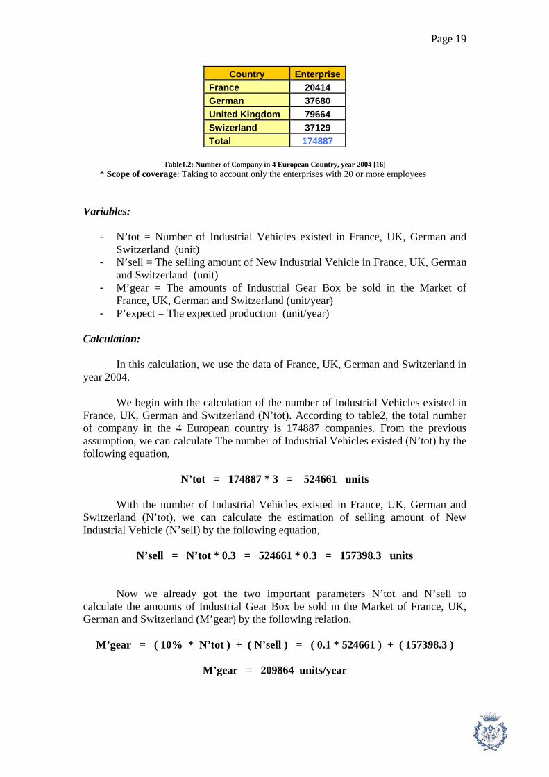
Country Enterprise France 20414 German 37680 United Kingdom 79664 Swizerland 37129 Total 174887
Table1.2: Number of Company in 4 European Country, year 2004 [16]
* Scope of coverage: Taking to account only the enterprises with 20 or more employees Variables:
- N’tot = Number of Industrial Vehicles existed in France, UK, German and Switzerland (unit)
- N’sell = The selling amount of New Industrial Vehicle in France, UK, German and Switzerland (unit)
- M’gear = The amounts of Industrial Gear Box be sold in the Market of France, UK, German and Switzerland (unit/year)
- P’expect = The expected production (unit/year) Calculation:
In this calculation, we use the data of France, UK, German and Switzerland in year 2004.
We begin with the calculation of the number of Industrial Vehicles existed in France, UK, German and Switzerland (N’tot). According to table2, the total number of company in the 4 European country is 174887 companies. From the previous assumption, we can calculate The number of Industrial Vehicles existed (N’tot) by the following equation,
N’tot = 174887 * 3 = 524661 units
With the number of Industrial Vehicles existed in France, UK, German and Switzerland (N’tot), we can calculate the estimation of selling amount of New Industrial Vehicle (N’sell) by the following equation,
N’sell = N’tot * 0.3 = 524661 * 0.3 = 157398.3 units
Now we already got the two important parameters N’tot and N’sell to calculate the amounts of Industrial Gear Box be sold in the Market of France, UK, German and Switzerland (M’gear) by the following relation,
M’gear = ( 10% * N’tot ) + ( N’sell ) = ( 0.1 * 524661 ) + ( 157398.3 )
M’gear = 209864 units/year

Page 20
Finally, we can estimate the expected production of our company for the year 2009 - 2012 ( in France, UK, German and Switzerland ) by considering that our market share is 5%, the calculation is shown below,
P’expect = 5% * M’gear = 0.05 * 209864 = 10493 units/year
We expect that the selling amount for France, UK, German and Switzerland
will increase 25% of P’expect every year continuously. So The selling amount from year 2009 – 2012 are : For year 2009 = 0.25 * P’expect = 0.25 * 10493 = 2623.25 units/year For year 2009 = 0.50 * P’expect = 0.50 * 10493 = 5246.5 units/year For year 2009 = 0.75 * P’expect = 0.75 * 10493 = 7869.75 units/year For year 2009 = 1 * P’expect = 1 * 10493 = 10493 units/year The total expected production are shown in the following table :
Year In Spain
(units/year) In Europe
(units/year) Total
(units/year) 2008 7513 0 7513 2009 7513 2623.25 10136.25 2010 7513 5246.5 12759.5 2011 7513 7869.75 15382.75 2012 7513 10493 18006
Table1.3: Total expected production from year 2008-2012
1.7. Conclusion : As we can see in Table3, the expected productions are not too large in year 2008 and it could be possible to employ Manual Machine. However if we observe the following year, the amount of expected productions are increasing year by year. In this case, it seems to be unsuitable to employ Manual Machine due to its low capacity and flexibility. Due to this reason, it would be better to choose CNC Machine for the main process and Manual Machine for the support function.

Page 21
2. Manufacturing Process of “ Shaft 1 “
2.1. The raw material: In order to machine this part, we use cylindrical bar steel 16 Mn Cr 5 with diameter 73 mm because we have to add 1.5 mm. to the final shape ( Maximum diameter of part is 70 mm.) in radial direction to be machined in Finishing Operation. 2.2. Phase 10: The cylindrical bars usually come with the long length shape. To be suitable for the Lathe Machine, the bars have to be cut by Manual Disc Saw Machine. The total distance of the final shape is 172.75 mm., we have to add 1.5 mm. for the both end of bar to be machine in Finishing Operation. So we have to cut the bar to have the length 175.75 mm. with the tolerance +1, -0 mm.
The calculation can be done by the same method as milling machine in the following step. In this case we consider that the diameter of disc (d) is 210 mm. with the thickness (b) 2 mm. The number of teeth (zt) is 60 and the advance of teeth (az) is 0.015 mm. We use the cutting speed (Vc) 40 m/min and the mechanical efficiency (η) is 0.75. We use the maximum width of part to calculate the maximum power, so the cutting width (p) is 73 mm. and the cutting length (L) is also 73 mm. The results of the calculations are shown in table2.1.
Figure2.1: Operation of Phase10
Tool Data
Step d(mm) az(mm.) Zt(teeth) n(rpm) av(mm/turn) Vam(mm/min) 1 210 0.015 60 60.63 0.9 54.567
p(mm) b(mm) Fc(N) Pc(kW) Pm(kW) L(mm) tc(min) 73 2 262800 0.239 0.319 73 1.338
Table2.1: Calculation data of Phase10
2.3. Phase 20: This process employ CNC Lathe Machine by fix the part with fixing plate with hard jaws. The part will be fixed at one end and will be machined at another end.

Page 22
Step1: We start machining the part by taking out front surface. In this operation, we
employ Stellram cutting tool SNMG120408E-3G with the holder MSKNR/L-124B [2]. The tool insert SNMG120408E-3G is square shape which is suitable for machining front surface and rough machining. The tool is Right hand tool because we fix the part with Lathe Machine on the left.
Figure2.2: Operation of Phase20 Step1
Calculation of Step1: In this operation, we fix cutting speed Vc = 150 m/min which is the proper value for the material of tool and part. We employ CNC Lathe, so the tangential speed at the surface of part is always fixed at 150 m/min. The rotation speed will be vary due to the changing of diameter, but in this calculation we use the average diameter of this step to calculate the rotation speed by the formula below[1]. n = ( 1000 * Vc ) / ( π * d) (1)
Where: n = Average rotation speed of machine (rpm) Vc = Cutting speed (m/min) d = Average diameter of the process (mm.)
The advance of the tool can be calculate by knowing tool radius and the average roughness of the machined surface. With the tool information, we know that the edge radius of tool rp = 0.031 mm. and the average roughness of this process is Ra = 1.6 μm (see table1.1). The advance velocity a (mm/turn) is calculated by the formula below [1].
a = sqrt{(Ra * rp)/25} (2)
Where: a = Advance velocity of tool (mm/turn) Ra = Average roughness of the surface (μm) rp = Radius of the edge of tool (mm.)

Page 23
Class of rugosity Ra (μm)N12 50 N11 25 N10 12.5 N9 6.3 N8 3.2 N7 1.6 N6 0.8 N5 0.4 N4 0.2 N3 0.1 N2 0.05 N1 0.025
Table2.2: Class of surface rugosity [1]
The cutting force required for this process (Fc) is needed to be calculated in
order to calculate the machine power in the following step. By knowing that the cutting depth of this step (p) is equal to 1.5 mm and the value of σt and k from table1.2, we can obtain Fc by utilizing the following formula [1]. Fc = k * σt * S (3)
Where: k = constant depending on the type of material k = 3 for elastic material k = 5 for less or non elastic material (ex. Casting ) σt = Resistant of traction stress of material (N/mm2) S = Cutting surface perpendicular to the cutting velocity (mm2) S = a * p ; a = advance velocity (mm/turn) p = Cutting depth (mm.)
The cutting power (Pc) and the machine power (Pm) will be calculated in order to choose the proper machine. The formulas are shown below[1]. Pc = (Fc * Vc)/60000 (4)
Pm = Pc/η (5)
Where: Pc = Cutting power required to cut material (kW) Pm = Machine power (kW) η = Efficiency of lathe machine = 0.7 – 0.8 We also have to calculate the cutting time tc. In order to calculate it, we have to find the cutting length and cutting velocity. Cutting length (L) is all paths that tool have to pass and cut the material. In this step, cutting length is 36.5 mm. ( from the surface to the center of the bar). The calculation process can be done by the following formula[1]. tc = L/Va (6)

Page 24
Va = a * n (7)
Where: L = Cutting length (mm.) Va = Cutting velocity (mm/min) a = advance velocity (mm/turn) n = rotation speed (rpm) Step2: This operation is to drill a hole for fixing with tail stock. The drilling tool has a special shape with angle 60 degree. In this case we use drill Garant 111050A with edge diameter 2 mm.
Figure2.3: Operation of Phase20 Step2
Calculation of Step2:
The material of drill is high speed steel, so the proper cutting speed Vc is equal to 25 * 0.8 m/min (For drill, we multiply the cutting speed of lathe or milling by 0.8). To calculate the rotation speed of tool, in this case the diameter of hole is not constant, so we use the average diameter to calculate (davg = (10 + 2)/2 = 6 mm.) The rotation speed can be calculated by the same formula as we have calculated in Step1. The advance speed of drill depends on the diameter of drill. The formula below shows how to calculate it [1]. a = d / 100 (8)
Where: a = advance speed of drill (mm/turn) d = average diameter of drill (mm) Generally, normal drill has 2 cutting edges. To calculate the cutting force of drilling operation, we consider only one side and finally we multiply by 2 to have to whole cutting force for drill. The formula is shown below [1]. Fc = 2 * k * σt * (a/2) * (d/2) (9)
Where: Fc = cutting force (N) k = constant depending on the type of material k = 3 for elastic material k = 5 for less or non elastic material (ex. Casting ) σt = Resistant of traction stress of material (N/mm2)

Page 25
a = advance speed of drill (mm/turn) d = average diameter of drill (mm) The cutting power required for cutting process (Pc) is the product of cutting force Fc and the average cutting velocity (0.8 * Vc)/2. If we divide Pc by drilling efficiency (ηdrill), we will get the power required for the machine. The formulas are shown below [1]. Pc = Fc * (0.5 * 0.8 * Vc) /60000 (10)
Pm Pc / ηdrill (11)
Where: Pc = cutting required to cut the material (kW) Pm = the power required for the machine ηdrill = efficiency of drill = 0.7 – 0.8 The cutting time for this process (tc) can be calculated by utilizing the equations 6 and 7.
Step rp(mm) d(mm) n (rpm) p(mm) Ra(mm) a(mm/turn) S(mm2) 1 0.031 36.5 1308 1.5 1.6 0.045 0.067 2 6 1061 0.06
Step Fc(N) Pc(kW) Pm (kW) L (mm) Va(mm/min) tc(min)
1 120 0.301 0.401 36.5 58.267 0.626 2 324 0.027 0.036 10.6 63.662 0.167
Table2.3: Calculation data of Phase20
2.4. Phase30: This Phase is almost the same process as in Phase20. We only change the machining surface to the other end of the raw part and following the operation in Step1 and Step 2 of Phase20.
Figure2.4: Operation of Phase30 Step1

Page 26
Figure2.5: Operation of Phase30 Step2
Step rp(mm) d(mm) n (rpm) p(mm) Ra(mm) a(mm/turn) S(mm2)
1 0.031 36.5 1308 1.5 1.6 0.045 0.067 2 6 1061 0.06
Step Fc(N) Pc(kW) Pm (kW) L (mm) Va(mm/min) tc(min)
1 120 0.301 0.401 36.5 58.267 0.626 2 324 0.027 0.036 10.6 63.662 0.167
Table2.4: Calculation data of Phase30
2.5. Phase40: This process employ CNC Lathe Machine by fix the part with fixing plate with hard jaws at one end. The part will be fixed by pressing tail stock at the 2 ends. It will be driven by the jaws at one end. The advantage of this fixing system is that we can machine the profile of the part in only one phase (without changing of fixing position) Step1: This step is to do rough machining. We will machine the part to be similar to the final profile but adding 1.5 mm. in radius and axial direction for finishing operation. The tool we employ is Stellram cutting tool SNMG120408E-3G with the holder MSKNR/L-124B, the same tool as Phase20 Step1.
Figure2.6: Operation of Phase40 Step1

Page 27
Calculation of Step1: In order to calculate rotation speed (n), cutting force (Fc), cutting power (Pc), machine power (Pm), cutting time (tc) and advance velocity (Va), all can be calculate by the equations 1,3,4,5,6 and 7. In this step, we use the average diameter to calculate the rotation speed as we have said in the calculation of phase20 step1 but we use the cutting speed (Vc) for rough machining (see table1.2).
The advance speed for rough machining is 0.5-0.8 mm/turn [1], so it’s not necessary to define the surface roughness (Ra). The only different in this step is the way to calculate L. This step is the rough machining by utilizing CNC Lathe machine and fix cycle. We use the cutting depth of each pass (p) 3 mm. By considering the manner of fix cycle path, we can calculate the total cutting length (L) by the equation below.
L = (5*89.75) + (1*37.75) + (5*23.5) + (2*78) + (5*33) + (1*29) = 954 mm.
Step2: This step is to machine finishing surface. The part will have almost the same shape as the final part after this step. We use Stellram tool insert DNMG150408E-3G and tool holder MDJNR/L-124B, both right and left hand.
Figure2.7: Operation of Phase40 Step2 Calculation of Step2: In order to calculate rotation speed (n), advance speed (a), cutting force (Fc), cutting power (Pc), machine power (Pm), cutting time (tc) and advance velocity (Va), all can be calculate by the equations 1,2,3,4,5,6 and 7. In this step, we use the average diameter to calculate the rotation speed as we have said in the calculation of phase20 step1 and we use Vc for finishing surface with carbide tool (see table1.2). According to the drawing, the sign of rugosity class is N7 which is equal to the average roughness Ra = 1.6 μm. (see table1.1) and the edge radius of this tool (rp) is 0.031 mm. With these 2 values, we can find the advance velocity. In this step, we leave the material 0.15 mm. in radius direction at diameter 16 h5 mm. and 25 k6 mm. because they require high precision and need to be done by Grinding process. The cutting length in this step can be done in the similar way as rough machining. But in this process, we machine only 1 pass with cutting depth (p) 1.5 mm.
Page 28
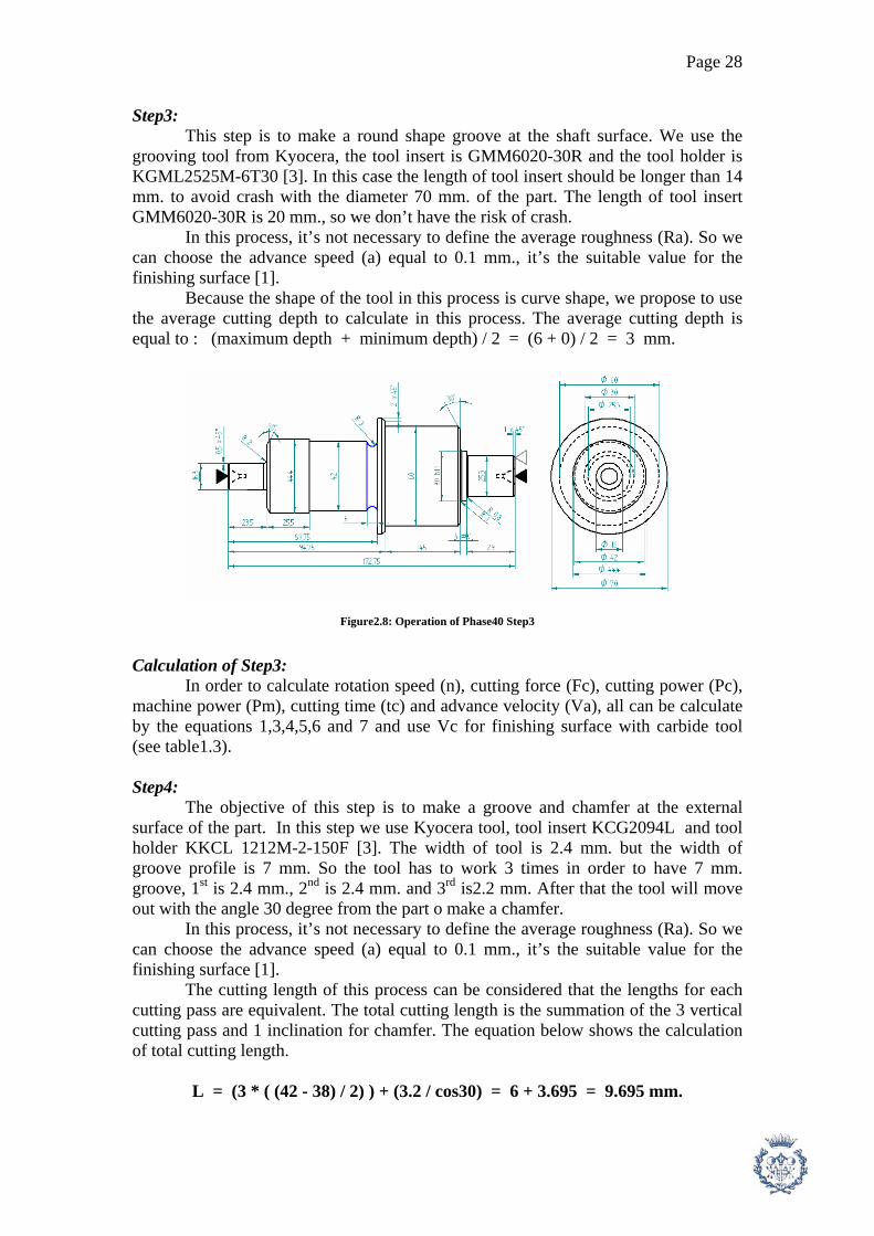
Step3: This step is to make a round shape groove at the shaft surface. We use the grooving tool from Kyocera, the tool insert is GMM6020-30R and the tool holder is KGML2525M-6T30 [3]. In this case the length of tool insert should be longer than 14 mm. to avoid crash with the diameter 70 mm. of the part. The length of tool insert GMM6020-30R is 20 mm., so we don’t have the risk of crash. In this process, it’s not necessary to define the average roughness (Ra). So we can choose the advance speed (a) equal to 0.1 mm., it’s the suitable value for the finishing surface [1].
Because the shape of the tool in this process is curve shape, we propose to use the average cutting depth to calculate in this process. The average cutting depth is equal to : (maximum depth + minimum depth) / 2 = (6 + 0) / 2 = 3 mm.
Figure2.8: Operation of Phase40 Step3
Calculation of Step3: In order to calculate rotation speed (n), cutting force (Fc), cutting power (Pc), machine power (Pm), cutting time (tc) and advance velocity (Va), all can be calculate by the equations 1,3,4,5,6 and 7 and use Vc for finishing surface with carbide tool (see table1.3). Step4: The objective of this step is to make a groove and chamfer at the external surface of the part. In this step we use Kyocera tool, tool insert KCG2094L and tool holder KKCL 1212M-2-150F [3]. The width of tool is 2.4 mm. but the width of groove profile is 7 mm. So the tool has to work 3 times in order to have 7 mm. groove, 1st is 2.4 mm., 2nd is 2.4 mm. and 3rd is2.2 mm. After that the tool will move out with the angle 30 degree from the part o make a chamfer. In this process, it’s not necessary to define the average roughness (Ra). So we can choose the advance speed (a) equal to 0.1 mm., it’s the suitable value for the finishing surface [1]. The cutting length of this process can be considered that the lengths for each cutting pass are equivalent. The total cutting length is the summation of the 3 vertical cutting pass and 1 inclination for chamfer. The equation below shows the calculation of total cutting length.
L = (3 * ( (42 - 38) / 2) ) + (3.2 / cos30) = 6 + 3.695 = 9.695 mm.

Page 29
Figure2.9: Operation of Phase40 Step4 Calculation of Step4: In order to calculate rotation speed (n), cutting force (Fc), cutting power (Pc), machine power (Pm), cutting time (tc) and advance velocity (Va), all can be calculate by the equations 1,3,4,5,6 and 7 and use Vc for finishing surface with carbide tool (see table1.3). Step5: The objective of this step is to make a groove at the external surface of the part. In this step we use Kyocera tool, tool insert TGF32R130 and tool holder KTGFRL1010K-16F [3]. The width of this tool is exactly 1.3 mm., so we need only 1 cutting pass for this step. In this process, it’s not necessary to define the average roughness (Ra). So we can choose the advance speed (a) equal to 0.1 mm., it’s the suitable value for the finishing surface [1].
Figure2.10: Operation of Phase40 Step5
Calculation of Step5: In order to calculate rotation speed (n), cutting force (Fc), cutting power (Pc), machine power (Pm), cutting time (tc) and advance velocity (Va), all can be calculate by the equations 1,3,4,5,6 and 7 and use Vc for finishing surface with carbide tool (see table1.2).

Page 30
Step rp(mm) d(mm) n (rpm) p(mm) Ra(mm) a(mm/turn) S(mm2)
1 0.031 44.057 1084 3 0.5 1.5 2 0.031 41.143 1393 1.5 1.6 0.045 0.067 3 39 1469 3 0.1 0.3 4 40 1432 2.4 0.1 0.24 5 24.6 2329 1.3 0.1 0.13
Step Fc(N) Pc(kW) Pm (kW) L (mm) Va(mm/min) tc(min)
1 2700 6.75 9 954 541.87 1.761 2 120 0.361 0.481 222.3 62.03 3.583 3 540 1.62 2.16 3 146.912 0.02 4 432 1.296 1.728 9.695 143.239 0.068 5 234 0.702 0.936 0.7 232.91 0.003
Table2.5: Calculation data of Phase40
2.6. Phase50:
This phase we move the part to CNC Milling Machine. The part will be fixed by the Index Plate with soft jaws which is suitable for cylindrical part and it’s possible to rotate the part. Step1: This step is to make external grooves of section C-C. The grooves have gear shape which need a special tool to machine. The tool we use in this process should has the shape according to DIN 5480.
Figure2.11: Operation of Phase50 Step1
Calculation of Step1: We have to start the calculation by finding the gear module of the part. The module (m) will be necessary for the next step. It can be calculated by the following formula [1]. m = dp / zp (12)
Page 31
Where: m = gear module dp = pitch diameter (mm.) zp = number of teeth The next step is to choose the number of teeth of milling tool from catalog (see table1.7). For ex. We choose tool with 22 teeth, we get number of tool (Nm) equal to 4.Then we shall find the tool size by the following equation [1]. Size = m / Nm (13) Where: Size = tool size (see table1.6) m = gear module Nm = Number of tool With the Size obtained from equation13, we can get the external diameter of tool from table1.6. This external diameter let us be able to calculate the rotation speed of tool. The formula is shown below [1]. The cutting Vc is chosen from table1.2. n = (1000 * Vc) / (pi * d) (14) Where: n = rotation speed tool Vc = Cutting speed d = external diameter of tool The next step is to calculate the advance speed (av) of milling tool. The formula is shown below [1]. av = az * z (15) or Vam = az * z * n (16) Where: av = advance speed of tool (mm/turn) z = number of teeth (teeth/turn) az = the distance between tool’s teeth (mm/tooth), choose from table1.8 Vam = advance speed of tool in mm/min n = rotation speed tool
The cutting force required for this process (Fc) is needed to be calculated in order to calculate the machine power in the following step. We choose cutting depth of each pass p = 2 mm. and the width of tool b = (3.65+1.5)/2 = 2.575 mm. (the avg of tool profile), the value of σt and k are from table1.2, we can obtain Fc by utilizing the following formula [1]. Fc = k * σt * p * b (17) Where: k = constant depending on the type of material k = 3 for elastic material k = 5 for less or non elastic material (ex. Casting ) σt = Resistant of traction stress of material (N/mm2)

Page 32
p = cutting depth of each pass (mm) b = average width of the cutting profile (mm)
The cutting power (Pc) and the machine power (Pm) will be calculated in order to choose the proper machine. The formulas are shown below[1]. Pc = (Fc * Vam) / 60000000 (18) Pm = Pc / ηmill (19) Where: Pc = Cutting power required to cut material (kW) Pm = Machine power (kW) η = Efficiency of milling machine = 0.6 – 0.75
We also have to calculate the cutting time tc. In order to calculate it, we have to find the cutting length and cutting velocity. Cutting length (L) is all paths that tool have to pass and cut the material. In this step, cutting length 0f each pass is 32 mm. and the tool will repeat 28 passes. So, the total cutting length is equal to 32 * 28 = 896 mm. The calculation process can be done by the following formula[1].
tc = L / Vam (20)
Where: tc = cutting time (min) L = total cutting length (mm) Vam = advance speed of tool in mm/min
Tool Size 0.5 0.75 1 1.25 1.5 1.75 2 2.25 2.5 2.75 3 3.25 3.5 3.75 4 4.25 4.5 4.75OD
(mm.) 40 40 50 50 63 63 63 63 63 80 40 40 50 50 63 63 63 63 ID
(mm.) 16 16 16 16 22 22 22 22 22 27 16 16 16 16 22 22 22 22
Table2.6: Tool size data for gear shape tool [4]
Number of tool 1 2 3 4 5 6 7 8 Number of
teeth 12 to 13 14 to 16 17 to 20 21 to 25 26 to 34 35 to 54 55 - 134 more than
135
Table2.7: Number of tool data for gear shape tool [4]

Page 33
Material Cutting Speed
(m/min) Advance of teeth, az
(mm) Soft Cast Iron 200B 20 to 25 0.005 - 0.015 Hard Cast Iron 200B 9 to 12 0.005 - 0.01
Ductile Cast Iron 20 to 25 0.005 - 0.01 Steel 50 N/mm^2 25 to 50 0.005 - 0.025
Steel 600-700 N/mm^2 15 to 25 0.005 - 0.015 Steel 700-1100 N/mm^2 10 to 18 0.005 - 0.010
Stainless Steel 8 to 12 0.015 - 0.025 Soft Brass 30 to 45 0.005 - 0.03
Hard Brass and Bronze 15 to 22 0.005 - 0.01
Table2.8: Cutting speed and advance of teeth for different materials [4]
Tool Data Step Zp Dp m Nm Size d(mm) az(mm.) Zt(teeth) n(rpm) av(mm/turn) Vam(mm/min)
1 28 58 2.07 4 0.52 40 0.015 25 1194 0.375 447.623
p(mm) b(mm) Fc(N) Pc(kW) Pm(kW) V(mm3/min) L(mm) tc(min) 2 2.575 9270 0.069 0.099 2305.26 896 2.002
Table2.9: Calculation data of Phase50
2.7. Phase60:
We still use the CNC milling Machine in this phase and the part will be fixed by the Index Plate with soft jaws. Step1: The purpose of this process is to drill 3 holes with 5 mm. diameter and deep 10 mm at section A-A. The 3 holes should be 120 degree between each other. We choose the drill Garant drill 113260 diameter 5 mm. [4] which is suitable for this material. This step is to prepare the hole for the next step which will be done by Mandrel Drill in order to have diameter 8 H7 mm. Because normal drill can make only a hole with the precision IT 9-10 but Mandrel Drill can reach IT 8-9.
Figure2.12: Operation of Phase60 Step1

Page 34
Calculation of Step1: The calculation of this step can be done by follow the method and formula in Phase20 Step2. We use the diameter 5 mm. and the depth 30 mm. The total cutting length is the summation of the depth of the 3 holes. Step2: In this step, we will increase the hole diameter to 8 H7 mm. by utilizing Mandrel Drill. We choose the drilling tool Garant Mandrel Drill 163500 diameter 8 mm.[4]. The process is similar to the previous step.
Figure2.13: Operation of Phase60 Step2
Calculation of Step2; The calculation of this step can be done by follow the method and formula in Phase20 Step2. We use the diameter 8 mm. and the depth 30 mm. The total cutting length is the summation of the depth of the 3 holes Step3: This step is to make external grooves of section A-A. The grooves have gear shape which need a special tool to machine. The tool we use in this process should has the shape according to the data in table1.10.
Table2.10: Data of external groove at section A-A

Page 35
Figure2.14: Operation of Phase60 Step3
Calculation of Step3: Every calculation of this step is similar to Phase50 Step1. We can use the formula 12,13,14,15,16,17,18,19 and 20 to calculate it with the data in table1.6, 1.7, 1.8. In this case, we choose the number of tool’s teeth (z) equal to 25 and the average width of tool’s profile (b) is (5.84 + 4.38) / 2 = 5.11 mm.
Tool Data Step Zp Dp m Nm Size d(mm) az(mm.) Zt(teeth) n(rpm) av(mm/turn) Vam(mm/min)
1 5 1273 0.05 63.662 2 8 795.8 0.08 63.662 3 12 41.2 3.43 4 0.86 40 0.015 25 1194 0.375 447.623
Step p(mm) b(mm) Fc(N) Pc(kW) Pm(kW) V(mm3/min) L(mm) tc(min)1 225 0.038 0.054 30 0.471 2 576 0.046 0.066 30 0.471 3 2 5.11 18396 0.137 0.196 4574.71 306 0.684
Table2.11: Calculation data of Phase60
2.8. Phase70: This phase is the manual operation to protect the small slot groove from carburizing operation. We shall paint the slot by anti-carburizing paint because the width and the depth of the slot are quite small, their distances can be changed if we let them pass the carburizing process.

Page 36
Figure2.15: Operation of Phase70
2.9. Phase80: We will do the Heat Treatment for this part by Carburizing Process. We will heat the part to 900 – 930 C in the carburizing oven which has more concentration of carbon than in the part. The time required for Carburizing Process is 720 min/lot ( 1 lot contains 20 parts). Then we have to do Quenching process which required 180 min/lot and finally Tempering process which required 30 min/lot. The total time required for this phase is 930 min/lot or 46.5 min/part ( This operation will be done by the external company ). 2.10. Phase90: The part after heat treatment process could be bent and need to be straightened. This operation will solve this problem by straightening the part with sensitive press machine.
Figure2.16: Operation of Phase90
2.11. Phase100: We shall move the part to the Manual Grinding Machine which is the last operation. The part will be fixed with axial fix at the ends of shaft by Driving Point with soft jaws.

Page 37
Step1: The purpose of this step is to grind the part at the diameter 16.3 mm. to be 16 h5 mm. The tool we employ in this step is A46K5V [1], the external diameter of grinder (d) is 150 mm. and its thickness is 30 mm. In this kind of machine, the part can rotate with a constant tangential speed (Vat) and move in axial direction with constant speed (Val) while the tool will rotate with high rotation speed (n) and can move in the radius direction toward the part with constant speed (Vaf). In general, Vat is between 10 – 15 m/min [1] , Val is (1/4 to 1/3) * the thickness of grinder [1] and Vaf is between 0.1 - 0.2 mm. in radius direction [1]. For the Grinding Operation, the cutting speed (Vc)depends on the type of Binder material. The values of Vc are shown in Table1.12. By the way, the maximum rotation speed is limited by the capability of the machine, so we fix the maximum rotation speed at 1800 rpm.
Figure2.17: Operation of Phase100 Step1
Binder Cutting Speed Vc (m/s) Ceramic 30
50 Organic 80 (with carbon fiber) Metallic >80 (depends of the machine)
Magnesium 20 Silicate 30 Shellac 30 Rubber 30
Table2.12: Cutting speed (Vc) for grinding process [1]
Calculation of Step1: The rotation speed of the machine can be calculated by using the value Vc from table 1.12 and the diameter of tool. The formula is shown below. n = (Vc * 60000) / (pi * d) (21) Where: n = rotation speed of grinder (rpm) Vc = cutting speed from table1.12 (m/s) d = external diameter of grinder (mm)

Page 38
By the way, the maximum rotation speed of tool is fixed by the capability of machine. So we fix the maximum rotation velocity at 1800 rpm. The Cutting Force (Fc) has to be calculated in order to find the machine power in the following steps. The formula is shown below. Fc = σt * k * Val * p (22) Where: k = constant depending on the type of material k = 3 for elastic material k = 5 for less or non elastic material (ex. Casting ) σt = Resistant of traction stress of material (N/mm^2) Val = Speed of tool in axial direction = 0.25 * b = 0.5 mm/turn b = The thickness of tool, in this case is 2 mm. p = the cutting depth of each pas (mm) = 0.01 – 0.02 mm [1]
The cutting power (Pc) and the machine power (Pm) will be calculated in order to choose the proper machine. The formulas are shown below[1]. Pc = (Fc * Vc) / 1000 (23)
Pm = Pc / η (24)
Where: Pc = Cutting power required to cut material (kW) Pm = Machine power (kW) Vc = Cutting speed, in this case is 30 m/s η = Efficiency of grinding machine = 0.7 – 0.8 The idea to calculate the cutting time (tc) is to multiply the number of cutting pass (Ncut) with the time required for each pass (tpass). The number of cutting pass is to divide the total cutting distance by the cutting depth of each pass. The time required for each pass depends on the rotation speed of the part. The formulas are shown below [1]. Ncut = L / p (25) tpass = L / ( np * Val ) (26) tc = Ncut * tpass (27) Where: Ncut = number of cutting pass required L = total cutting length (mm), in this case is equal to 0.15 mm. p = cutting depth of each pass (mm) np = Rotation speed of part (rpm) = (Vat * 1000) / (dp * pi) dp = Diameter of part at the position that will be grinded (mm) Vat = rotation speed with a constant tangential speed (m/min) tpass = time required for each cutting pass (min) tc = total cutting time foe the process (min)

Page 39
Step2: We change the machining position to diameter 25.3 and follow the same process as Step1.
Figure2.18: Operation of Phase100 Step2
Calculation of Step2: The calculations can be done by use the same equations 21,22,23,24,25,26 and 27 in Shaft1 Phase100 .
Step d(mm) n (rpm) np (rpm) p(mm) Vat(m/min) Val(mm/turn) Vaf(mm/turn) S(mm2) 1 150 1800 298.416 0.015 15 0.5 0.01 0.032 150 1800 190.986 0.015 15 0.5 0.01 0.03
Fc(N) Pc(kW) Pm (kW) L (mm) Ncut tpass(min) tc(min)
13.5 0.405 0.54 23.5 10 0.157 1.575 13.5 0.405 0.54 23.9 10 0.250 2.503
Table2.13: Calculation data of Phase100
2.12. Calculation of Cycle Time for Shaft1: The Cycle Time is the total time used for machining 1 part. It includes with Machining time (tm) , Tool changing time (tch) , Phase changing time (tph) , Machine preparation time (tpre) , Time for taking out the finished part (thmp) , Time for un-machine phase (tun) : Cycle Time = tm + tch + tph + tpre + thmp + tun (48) Machine time (tm) is the time required during the machining operation, from tool moving into the part, do the machining operation and move out from the part, then it changes the tool and repeat the operations. The estimate time for tool moving into the part is 2 s, tool moving out from the part is 3 s and the machining operations are in the previous calculations.

Page 40
Tool changing time (tch) is calculated by considering that the life time of tool (tedge) is 7200 s (2 hr) for cutting tool and 3600 s (1 hr) for drilling. We assume that the time for changing the new tool (tchtool) when it’s worn out is 120 s for cutting tool and 90 s for drilling. The formulas are shown below. tch = tchtool / n (49) n = tedge / tc (50) Where: tch = Tool changing time for each part (s/part) tchtool = Time for changing the new tool (s) n = Number of part able to be machined by 1 tool (part) tedge = Life time of tool (s) tc = Machining time for each operation (s) Phase changing time (tph) is the time required for changing phase, because we need time to change the fixing position or fixing type as well. We estimate that the Phase changing time (tph) is 120 s for each changing. Machine preparation time (tpre) is needed when we change the machine. It’s for setting up the machine and the part before start the operation. W estimate that the Machine preparation time (tpre) for CNC controlled machine per batch is 3600 s and 300 s for manual machine. 1 batch of part is the part manufactured in 1 month, so it is the annual production divide by 11 months. According to the Marketing Study, the annual production is 7513 part/year. So 1 batch = 7513 / 11 = 683 parts/batch. In reality, we have to setup the machine only 1 time per 1 batch of parts, so the Machine preparation time (tpre) per 1 part is 3600 / 683 = 5.27 s/part ( for CNC Machine) and 300 / 683 = 0.439 s/part. Time for taking out the finished part (thmp) is required when the worker stop the machine and take the finished part out. We estimate that we required 15 s for thmp. Time for un-machine phase (tun) is for the phase that we don’t employ any machine, for example phase 70, 80, 90 of shaft1. We define the Time for un-machine phase (tun) by considering the theory and the reality of each task. The results of the calculation of cycle time are shown in table2.14.

Page 41
Phase Step Task tm (s)
tch (s)
tph (s)
tpre (s)
thmp (s)
tun (s)
10 1 Cut the part 80.27 0.439 15 Cycle Time (s) 95.707
20 1 Tool moves into part 2 5.271 Frontal machining 37.56 Tool move out from the part 3 0.628 2 Tool moves into part 2 Point drilling 10.02 Tool move out from the part 3 0.25 15 Total Time (s) 57.58 0.878 0 5.2709 15 0 Cycle Time (s) 78.729
30 1 Tool moves into part 2 120 Frontal machining 37.56 Tool move out from the part 3 0.628 2 Tool moves into part 2 Point drilling 10.02 Tool move out from the part 3 0.25 15 Total Time (s) 57.58 0.878 120 0 15 0 Cycle Time (s) 193.458
40 1 Tool moves into part 2 120 Rough machining 105.6 Tool move out from the part 3 1.761 2 Tool moves into part 2 Finish surface machining 215 Tool move out from the part 3 3.583 3 Tool moves into part 2 Curve groove machining 1.225 Tool move out from the part 3 0.02 4 Tool moves into part 2 External groove width 7 mm. 4.061 Tool move out from the part 3 0.068 5 Tool moves into part 2
External groove width 1.3 mm. 0.18
Tool move out from the part 3 0.003 15 Total Time (s) 351.1 5.435 120 0 15 0 Cycle Time (s) 491.515
50 1 Tool moves into part 2 5.271 Groove section C-C 120.1 Tool move out from the part 3 2.002 15 Total Time (s) 125.1 2.002 0 5.271 15 0 Cycle Time (s) 147.393
60 1 Tool moves into part 2 120 Drill 3 holes dia. 5 mm. 28.27 Tool move out from the part 3 0.707 2 Tool moves into part 2 Drill 3 holes dia. 8 H7 mm. 28.27 Tool move out from the part 3 0.707 3 Tool moves into part 2 Groove section A-A 41.02 Tool move out from the part 3 15 Total Time (s) 112.6 1.414 120 0 15 0

Page 42
Cycle Time (s) 248.979 70 1 Anti-carburizing paint. 60 80 1 Carburizing and quenching 279090 1 Straightening of the shaft 90
100 1 Grinding of Dia 16 h5 94.5 0.439 2 Grinding of Dia 25 k6 150.2 15 Total Time (s) 244.7 0 0 0.439 15 0 Cycle Time (s) 260.106
Total Time (s) 1029 10.61 360 11.42 105 2940 Total Cycle Time (s) 4455.888
Table2.14: Cycle Time for Shaft1
Rough Machining Finish Machining
Carbon Steel HSS Tungsten Carbide Carbon Steel HSS
Tungsten Carbide
400 N/mm^2 12 25 200 20 30 300 Steel 600 N/mm^2 10 20 150 15 25 180
800 N/mm^2 8 15 100 12 20 130 Brass 20 30 300 32 40 400
Bronze 12 18 200 20 25 300 Aluminum 40 60-200 75-300 100 100-700 200-2000
Table2.15: Proper Cutting Speed [1]

Page 43
3. Manufacturing Process of “ Shaft 2 “
3.1. The raw material: In order to machine this part, we use cylindrical bar steel 16 Mn Cr 5 with diameter 58 mm because we have to add 1.5 mm. to the final shape ( Maximum diameter of part is 55 mm.) in radial direction to be machined in Finishing Operation. 3.2. Phase 10:
The cylindrical bars usually come with the long length shape. To be suitable for the Lathe Machine, the bars have to be cut by Manual Saw Machine. The total distance of the final shape is 137.5 mm., we have to add 1.5 mm. for the both end of bar to be machine in Finishing Operation. So we have to cut the bar to have the length 140.5 mm. with the tolerance +1,-0 mm. The calculation of this phase can be done in the same way as Shaft1 ( by using the method of milling machine ) and the results are shown in table3.1.
Figure3.1: Operation of Phase10
Tool Data Step d(mm) az(mm.) Zt(teeth) n(rpm) av(mm/turn) Vam(mm/min)
1 210 0.015 60 60.63 0.9 54.567
p(mm) b(mm) Fc(N) Pc(kW) Pm(kW) L(mm) tc(min) 58 2 208800 0.19 0.253 58 1.063
Table3.1: Calculation data of Phase10
3.3. Phase 20: This process employ CNC Lathe Machine by fix the part with fixing plate with hard jaws. The part will be fixed at one end and will be machined at another end. Step1:
We start machining the part by taking out front surface. In this operation, we employ Stellram cutting tool SNMG120408E-3G with the holder MSKNR/L-124B [2]. The tool insert SNMG120408E-3G is square shape which is suitable for machining front surface and rough machining. The tool is Right hand tool because we fix the part with Lathe Machine on the left.

Page 44
Figure3.2: Operation of Phase20 Step1
Calculation of Step1: The calculation in this step is similar to the one of Shaft1 Phase20 Step1. The only difference is the average diameter of the machining position to calculate the rotation speed, in this case d = (58 + 0) / 2 = 29 mm. We can calculate by utilizing the equations 1,2,3,4,5,6 and 7. Step2: This operation is to drill a hole for fixing with tail stock. The drilling tool has a special shape with angle 60 degree. In this case we use drill Garant 111050A with edge diameter 2 mm.
Figure3.3: Operation of Phase20 Step2
Calculation of Step2: The calculation in this step is exactly the same as the one of Shaft1 Phase20 Step1. We can calculate by utilizing the equations 6,7,8,9,10 and 11. Step3: This step is to drill a hole diameter 6.8 mm. deep 23 mm. in order to tap thread M8 x 1.25 in the next step. We choose the drilling tool Garant drill 113260 diameter 6.8 mm. maximum cutting length 34 mm. (more than 23 mm.) and total length 74 mm. The material of drill is suitable for steel with σt = 600 N/mm2
Calculation of Step3: The calculation in this step can be done by using equations 6,7,8,9,10 and 11. The diameter of drill is 6.8 mm. and the cutting velocity is 25 m/min.

Page 45
Figure3.4: Operation of Phase20 Step3
Step4: In this step, we shall make an internal thread M8 x 1.25 by tapping. The suitable cutting speed (Vc) for internal tapping is 8 m/min and the advance speed (a) equal to pitch (1.25 in this case). The tool employed in this step is Garant Tap 130180 M8 x 1.25 which is suitable for Steel 16Mn Cr5.
Figure3.5: Operation of Phase20 Step4
Calculation 0f Step4: The rotation speed can be found by using equation 1. The advance speed is fix at pitch mm/turn. With these data, we can find the total cutting time (tc) by the following equation. Va = n * a (28) tc = L / Va (29) Where: L = total cutting length (mm) or depth of internal thread Va = advance speed of tool (mm/min) a = advance speed of tool (mm/turn) n = rotation speed of tool (rpm)

Page 46
Step rp(mm) d(mm) n (rpm) p(mm) Ra(mm) a(mm/turn) S(mm2) 1 0.031 29 1646 1.5 1.6 0.045 0.067 2 6 1061 0.06 3 6.8 936.2 0.068 4 8 318.3 1.25
Step Fc(N) Pc(kW) Pm (kW) L (mm) Va(mm/min) tc(min) 1 120 0.301 0.401 29 73.335 0.395 2 324 0.027 0.036 10.6 63.662 0.167 3 416 0.035 0.046 23 63.662 0.361 4 21 397.887 0.053
Table3.2: Calculation data of Phase20 3.4. Phase30: This Phase is almost the same process as in Shaft1 Phase20. We only change the machining surface to the another end of the raw part and following the operation in Step1 and Step 2 of Phase20 of Shaft1.
Figure3.6: Operation of Phase30 Step1
Figure3.7: Operation of Phase30 Step2

Page 47
Step rp(mm) d(mm) n (rpm) p(mm) Ra(mm) a(mm/turn) S(mm2) 1 0.031 29 1646 1.5 1.6 0.045 0.067 2 6 1061 0.06
Step Fc(N) Pc(kW) Pm (kW) L (mm) Va(mm/min) tc(min)
1 120 0.301 0.401 29 73.335 0.395 2 324 0.027 0.036 10.6 63.662 0.167
Table3.3: Calculation data of Phase30
3.5. Phase40: This process employ CNC Lathe Machine by fix the part with fixing plate with hard jaws at one end. The part will be fixed by pressing tail stock at the 2 ends. It will be driven by the jaws at one end. The advantage of this fixing system is that we can machine the profile of the part in only one phase (without changing of fixing position) Step1: This step is to do rough machining. We will machine the part to be similar to the final profile but adding 1.5 mm. in radius and axial direction for finishing operation. The tool we employ is Stellram cutting tool SNMG120408E-3G with the holder MSKNR/L-124B, the same tool as Phase20 Step1.
Figure3.8: Operation of Phase40 Step1
Calculation of Step1: In order to calculate rotation speed (n), cutting force (Fc), cutting power (Pc), machine power (Pm), cutting time (tc) and advance velocity (Va), all can be calculate by the equations 1,3,4,5,6 and 7. In this step, we use the average diameter to calculate the rotation speed as we have said in the calculation of phase20 step1 of Shaft1 but we use the cutting speed (Vc) for rough machining (see table1.2).
The advance speed for rough machining is 0.5-0.8 mm/turn [1], so it’s not necessary to define the surface roughness (Ra). The only different in this step is the way to calculate L.

Page 48
This step is the rough machining by utilizing CNC Lathe machine and fix cycle. We use the cutting depth of each pass (p) 3 mm. By considering the manner of fix cycle path, we can calculate the total cutting length (L) by the equation below.
L = (3 * 84) + (2 * 41.5) + (2 * 27) + (3 * 45) + (1 * 30) = 554 Step2: This step is to machine finishing surface. The part will have almost the same shape as the final part after this step. We use Stellram tool insert DNMG150408E-3G and tool holder MDJNR/L-124B, both right and left hand.
Figure3.9: Operation of Phase40 Step2
Calculation of Step2: In order to calculate rotation speed (n), advance speed (a), cutting force (Fc), cutting power (Pc), machine power (Pm), cutting time (tc) and advance velocity (Va), all can be calculate by the equations 1,2,3,4,5,6 and 7. In this step, we use the average diameter to calculate the rotation speed as we have said in the calculation of phase20 step1 and we use Vc for finishing surface with carbide tool (see table1.2). According to the drawing, the sign of rugosity class is N7 which is equal to the average roughness Ra = 1.6 μm. (see table1.1) and the edge radius of this tool (rp) is 0.031 mm. With these 2 values, we can find the advance velocity. In this step, we leave the material 0.15 mm. in radius direction at diameter 25 h5 mm. and 40 k6 mm. because they require high precision and need to be done by Grinding process. The cutting length in this step can be done in the similar way as rough machining. But in this process, we machine only 1 pass with cutting depth (p) 1.5 mm. Step3: This step is to make a shape groove width 2.25 at the shaft surface. We use the grooving tool from Stellram, the tool insert is G217018500 and the tool holder is GR360121202 [2]. The width of this tool is 1.99 mm. while the width of groove is 2.25 mm. , so it’s necessary to do the operation 2 times. The total cutting length will be L = 2 * (0.715) = 1.43 mm.

Page 49
In this process, it’s not necessary to define the average roughness (Ra). So we can choose the advance speed (a) equal to 0.1 mm., it’s the suitable value for the finishing surface [1].
Figure3.10: Operation of Phase40 Step3
Calculation of Step3: In order to calculate rotation speed (n), cutting force (Fc), cutting power (Pc), machine power (Pm), cutting time (tc) and advance velocity (Va), all can be calculate by the equations 1,3,4,5,6 and 7 and use Vc for finishing surface with carbide tool (see table1.2). Step4:
The objective of this step is to make external thread M35 x 1.5 by turning operation. The tool we employ in this step is 11ER1.5ISO for insert part and ERNM1010H11 for holder part. This process will be done by CNC Milling Machine with fix cycle for thread. Refer to “ Computer Assisted Manufacturing “ , Joan Vivancos Calvet , the depth of thread M35 x 1.5 (pt) is 1.54 mm. and the number of pass for rough machining (np) is 6 passes. We shall leave the layer of material for finishing (pf) 0.2 mm. These 3 values will be used in the following calculation part. In this process, it’s not necessary to define the average roughness (Ra). So we can choose the advance speed (a) equal to 1.5 mm/turn with rotation speed 200 rpm which are suitable for this operation [1]. This operation has 6 times of rough machining and 1 time for finishing. So the total cutting length is L = 7 * 12.25 = 85.75 mm.

Page 50
Figure3.11: Operation of Phase40 Step4
Calculation of Step4: First of all, we have to find the cutting depth of each pass. The equation is shown below. p = (pt – pf) / np (30) Where: p = cutting depth of each pass (mm) pt = the depth of thread (mm) pf = layer of material left for finishing (mm) np = number of pass for rough machining The cutting force (Fc), cutting power (Pc), machine power (Pm), advance velocity (Va) and cutting time (tc) can be calculated by equations 3,4,5,6 and 7.
Step rp(mm) d(mm) n (rpm) p(mm) Ra(mm) a(mm/turn) S(mm2) 1 0.031 41.833 1141 3 0.5 1.5 2 0.031 38.933 1472 1.5 1.6 0.045 0.067 3 34.285 1671 1.99 0.1 0.199 4 35 200 0.223 1.5 0.335
Step Pc(kW) Pm (kW) L (mm) Va(mm/min) tc(min) 1 6.75 9 554 570.675 0.971 2 0.361 0.481 162 65.55 2.471 3 1.075 1.433 1.43 167.116 0.009 4 1.806 2.408 85.75 300 0.286
Table3.4: Calculation data of Phase40
3.6. Phase50: This phase we move the part to CNC Milling Machine. The part will be fixed by Index Plate with soft jaws which is suitable for cylindrical part and it’s possible to rotate the part.

Page 51
Step1: This step is to make external grooves of section C-C. The grooves have gear shape which need a special tool to machine. The tool we use in this process should has the shape according to DIN 5462.
Figure3.12: Operation of Phase50 Step1
Calculation of Step1:
In this step, we choose the number of tool’s teeth equal to 22 teeth, diameter primitive (dp) is 34 mm and the number of gear’s teeth is 8. All the calculation process can use the same formula as Shaft1 Phase50, equations 12, 13,14,15,16,17,18,19 and 20.
Tool Data
Step Zp Dp m Nm Size d(mm) az(mm.) Zt(teeth) n(rpm) av(mm/turn) Vam(mm/min)1 8 34 4.25 4 1.06 50 0.01 22 954.9 0.22 210.085
Step p(mm) b(mm) Fc(N) Pc(kW) Pm(kW) V(mm3/min) L(mm) tc(min)1 2 7.25 26100 0.091 0.131 3046.226 240 1.142
Table3.5: Calculation data of Phase50
3.7. Phase60:
We still use the CNC milling Machine in this phase and the part will be fixed by the Index plate with soft jaws. Step1: The purpose of this process is to make external grooves of section B-B. The grooves have gear shape which need a special tool to machine. The tool we use in this process should have the shape according to DIN 5480.

Page 52
Figure3.13: Operation of Phase60 Step1 Calculation of Step1: In this step, we choose the number of tool’s teeth equal to 25 teeth, diameter primitive (dp) is 40 mm and the number of gear’s teeth is 20. All the calculation process can use the same formula as Shaft1 Phase50, equations 12,13,14,15,16,17,18, 19 and 20. We choose cutting depth of each pass p = 2 mm. and the width of tool b = (8+6.5)/2 = 7.25 mm. (the average of tool profile). Step2: The purpose of this process is to make external grooves of section A-A. The tool for this process is Garant Milling 191080 , diameter 3 mm. , cutting length
Figure3.14: Operation of Phase60 Step2
Calculation of Step2: The calculations of this step will start with tool rotation speed. We can use equation 14 of shaft 1 with tool diameter 3 mm. Because of very small diameter, the rotation speed from calculation is too high and it could damage the machine. We have to set the maximum rotation speed of tool to prevent this problem. In this case, we set at 5500 rpm. In order to find advance speed, cutting force, cutting power, machine power and cutting time, we can use equations 15,16,17,18,19 and 20. In this operation, the cutting depth (p) is 2.5 mm, the cutting width (b) is 3 mm. ( equal to the tool diameter) and the cutting length (L) is 18.98 mm.

Page 53
Tool Data Step Zp Dp m Nm Size d(mm) az(mm.) Zt(teeth) n(rpm) av(mm/turn) Vam(mm/min)
1 20 40 2 4 0.5 40 0.015 25 1194 0.375 447.623 2 3 0.025 2 5500 0.05 275
Step p(mm) b(mm) Fc(N) Pc(kW) Pm(kW) V(mm3/min) L(mm) tc(min)1 2 3.3 11880 0.089 0.127 2954.314 670 1.497 2 2.5 3 13500 0.062 0.088 2062.5 18.98 0.069
Table3.6: Calculation data of Phase60
3.8. Phase70: This phase is the manual operation to protect the external and internal thread from carburizing operation. We shall paint the external thread by anti-carburizing paint and fill the hole of internal thread with bolt M8 x 1.25.
Figure3.15: Operation of Phase70 Step1
Figure3.16: Operation of Phase70 Step2

Page 54
3.9. Phase80: We will do the Heat Treatment for this part by Carburizing Process. We will heat the part to 900 – 930 C in the carburizing oven which has more concentration of carbon than in the part. The time required for Carburizing Process is 720 min/lot ( 1 lot contains 20 parts). Then we have to do Quenching process which required 180 min/lot and finally Tempering process which required 30 min/lot. The total time required for this phase is 930 min/lot or 46.5 min/part ( This operation will be done by the external company) . 3.10. Phase90: The part after heat treatment process could be bent and need to be straightened. This operation will solve this problem by straightening the part with press machine.
Figure3.17: Operation of Phase90
3.11. Phase100: We shall move the part to the Manual Grinding Machine which is the last operation. The part will be fixed with axial fix at the ends of shaft with Driving Point. Step1: The purpose of this step is to grind the part at the diameter 25.3 mm. to be 25 h5 mm. The tool we employ in this step is A46K5V [1], the external diameter of grinder (d) is 150 mm. and its thickness is 30 mm. In this kind of machine, the part can rotate with a constant tangential speed (Vat) and move in axial direction with constant speed (Val) while the tool will rotate with high rotation speed (n) and can move in the radius direction toward the part with constant speed (Vaf). In general, Vat is between 10 – 15 m/min [1] , Val is (1/4 to 1/3) * the thickness of grinder [1] and Vaf is between 0.1 - 0.2 mm. in radius direction [1]. For the Grinding Operation, the cutting speed (Vc)depends on the type of Binder material. The values of Vc are shown in Table1.12. By the way, the maximum

Page 55
rotation speed is limited by the capability of the machine, so we fix the maximum rotation speed at 1800 rpm.
Figure3.18: Operation of Phase100 Step1
Calculation of Step1:
The calculations can be done by use the same equations 21,22,23,24,25,26 and 27 in Shaft1 Phase100 . We only change the diameter of the part according to shaft2. Step2: We change the machining position to diameter 40.3 and follow the same process as Step1.
Figure3.19: Operation of Phase100 Step2
Calculation of Step2: The calculations can be done by use the same equations 21,22,23,24,25,26 and 27 in Shaft1 Phase100 . We only change the diameter of the part according to shaft2.

Page 56
Step d(mm) n (rpm) np (rpm) p(mm) Vat(m/min) Val(mm/turn) Vaf(mm/turn) S(mm2) 1 150 1800 191 0.015 15 0.5 0.01 0.03 2 150 1800 119.4 0.015 15 0.5 0.01 0.03
Fc(N) Pc(kW) Pm (kW) L (mm) Ncut tpass(min) tc(min) 13.5 0.405 0.54 27 10 0.283 2.827 13.5 0.405 0.54 15 10 0.251 2.513
Table3.7: Calculation data of Phase100
3.12. Calculation of Cycle Time for Shaft2:
Phase Step Task tm (s)
tch (s)
tph (s)
tpre (s)
thmp (s)
tun (s)
10 1 Cut the part 63.77 0.439 15 Cycle Time (s) 79.213
20 1 Tool moves into part 2 5.271 Frontal machining 37.56 Tool move out from the part 3 0.628 2 Tool moves into part 2 Point drilling 10.02 Tool move out from the part 3 0.25 15 3 Tool moves into part 2 Drill a hole dia. 6.8 mm. 21.68 Tool move out from the part 3 0.542 15 4 Tool moves into part 2 Tap M8 x 1.25 3.167 Tool move out from the part 3 0.079 15 Total Time (s) 92.42 1.499 0 5.271 45 0 Cycle Time (s) 144.194
30 1 Tool moves into part 2 120 Frontal machining 23.73 Tool move out from the part 3 0.396 2 Tool moves into part 2 Point drilling 10.02 Tool move out from the part 3 0.251 15 Total Time (s) 43.75 0.646 120 0 15 0 Cycle Time (s) 179.393
40 1 Tool moves into part 2 120 Rough machining 58.25 Tool move out from the part 3 0.971 2 Tool moves into part 2 Finish surface machining 148.3 Tool move out from the part 3 2.471 3 Tool moves into part 2 Grooving width 0.513 Tool move out from the part 3 0.05 4 Tool moves into part 2 Tap M35 x 1.5 17.15 Tool move out from the part 3 0.429 15 Total Time (s) 244.2 3.921 120 0 15 0

Page 57
Cycle Time (s) 383.115 50 1 Tool moves into part 2 5.271 Groove section C-C 68.52 Tool move out from the part 3 1.142 15 Total Time (s) 73.52 1.142 0 5.271 15 0 Cycle Time (s) 94.933
60 1 Tool moves into part 2 120 Grooving section B-B 89.81 Tool move out from the part 3 2.245 2 Tool moves into part 2 Grooving section A-A 4.141 Tool move out from the part 3 0.104 15 Total Time (s) 103.9 2.349 120 0 15 0 Cycle Time (s) 241.297
70 1 Anti-carburizing paint. 120 80 1 Carburizing and quenching 279090 1 Straightening of the shaft 90
100 1 Grinding of Dia 16 h5 169.6 0.439 2 Grinding of Dia 25 k6 150.8 15 Total Time (s) 320.4 0 0 0.439 15 0 Cycle Time (s) 335.882
Total Time (s) 942 9.557 360 11.42 135 3000 Total Cycle Time (s) 4458.027
Table3.8: Cycle Time for Shaft2

Page 58
4. Manufacturing Process of “ Casing “ 4.1. The raw material: The raw part of this process is UNE 38212L-212 (Aluminum casting) from casting. The casting part has the shape similar to the final shape. The shape of raw part from casting is not exactly same as the final shape because there are several limitations for casting. It need to be machined in the following steps. We use the raw part from casting process because the shape of casing is too difficult to be machined and it will have high cost. 4.2. Phase20: We fix the raw part horizontally with fixing clamp of CNC Milling Machine. Our machine is vertical milling machine, so the tool is rotating while the part can move in 3 axis. Step1: The purpose of this step is to make flat machining at the joining surface with the cutting depth 1.5 mm. We use milling tool Garant 181000 diameter 30 mm and thickness 30 mm. We choose tool’s diameter 30 mm. because the tool’s diameter has to cover the maximum thickness of the joining surface which is 15.25 mm.
Figure4.1: Operation of Phase20 Step1

Page 59
Calculation of Step1: Because the part is casting aluminum and the milling tool is tungsten carbide, so the cutting velocity should be from 75-300 m/min [1]. The milling tool Garant 181000 has external diameter 30 mm. and number of teeth is 6. In order to find advance speed, cutting force, cutting power, machine power and cutting time, we can use equations 15,16,17,18,19 and 20 of Shaft1. In this operation, the cutting depth (p) is 1.5 mm, the cutting width (b) is 15.25 mm. ( equal to the thickness of part because it’s less than the diameter of tool ). The cutting length (L) is the summation of the contour of the joining surface which is L = 848 mm. Step2: In this step, we will drill 14 holes of diameter 5 mm and deep 25 mm. These holes are for preparing to tap M6 in the following step. We use the drilling tool Garant 113260 diameter 5 mm.
Figure4.2: Operation of Phase20 Step2
Calculation of Step2: The calculation in this step can be done by using equations 6,7,8,9,10 and 11 of Shaft1. The diameter of drill is 5 mm. and the cutting velocity is 25 m/min. because the material of part is Aluminum casting. The depth of each hole is 25 mm. so the total cutting length (L) is 350 mm. Step3: In this step, we shall make an internal thread M6 x 1 by tapping and deep 18 mm. for 14 holes. The suitable cutting speed (Vc) for internal tapping is 8 m/min and the advance speed (a) equal to pitch (1 in this case).The tool employed in this step is Tap Garant 131130 M 6 x 1.

Page 60
Figure4.3: Operation of Phase20 Step3
Calculation of Step3: The calculation in this process can be done by using the equation 28 and 29 of Shaft2. Step4: We will drill 2 holes in this step. The holes are 6 mm. diameter (+0.25, +0.1 tolerance) and deep 15 mm. We use drilling tool Garant 113260 diameter 6 mm.
Figure4.4: Operation of Phase20 Step4
Calculation of Step4: The calculation in this step can be done by using equations 6,7,8,9,10 and 11 of Shaft1. The diameter of drill is 6 mm. and the cutting velocity is 80 m/min. because

Page 61
the material of part is Aluminum casting. The depth of each hole is 15 mm. so the total cutting length (L) is 30 mm. Step5: In this step, we will mill flat surface (1mm. depth) and increase the diameter of the 3 holes to be 32 H7 mm. We use milling tool Garant 191200 diameter 10 mm. , number of teeth 3 and cutting length 22 mm. We choose this tool because the tool’s diameter has to cover the maximum thickness of the 3 holes which is 5 mm. and the cutting length has to be longer than maximum depth of holes which are 20 mm.
Figure4.5: Operation of Phase20 Step5
Calculation of Step5: Because the part is casting aluminum and the milling tool is tungsten carbide, so the cutting velocity should be from 75-300 m/min [1]. The milling tool Garant 191200 has external diameter 10 mm. and number of teeth is 3. In order to find advance speed, cutting force, cutting power, machine power and cutting time, we can use equations 15,16,17,18,19 and 20 of Shaft1. In this operation, the cutting depth (p) is 0.5 mm, the cutting width (b) is 20 mm. ( we use the depth of hole because it’s the maximum cutting width of this step ). The cutting length (L) is the summation of the movement of tool which is L = 697.43 mm.

Page 62
Tool Data
Step d(mm) az(mm.) Zt(teeth) n(rpm) av(mm/turn) Vam(mm/min) p(mm) b(mm)1 30 0.025 6 1592 0.15 238.732 1.5 15.25 2 5 4074 0.05 203.718 3 6 424.4 1 424.413 4 6 3395 0.06 203.718 5 10 0.025 3 4775 0.075 358.099 0.5 20
Step Fc(N) Pc(kW) Pm(kW) V(mm3/min) L(mm) tc(min) 1 28594 0.1138 0.1625 5461.004 848 3.552 2 156.3 0.1563 0.2232 350 1.718 3 252 0.594 4 225 0.225 0.3214 30 0.147 5 12500 0.0746 0.1066 3580.986 697.43 1.948
Table4.1: Calculation data of Phase20
4.3. Phase30:
In this Phase, we will machine at the other side of part, so we have to turn the part up side down and fix the raw part horizontally with fixing clamp of CNC Milling Machine. Step1: In this step, we will make flat surface 1.5 mm. depth around and above the external diameter 83 mm. We use milling tool Garant 191200 diameter 10 mm. , number of teeth 3 and cutting length 22 mm. In this step, it’s possible to use another tool because the part surface to be machined is quite big. But we choose this tool because we already use it in the previous step, this let us reduce time to change tool and for the tool cost as well. Figure4.6: Operation of Phase30 Step1

Page 63
Calculation of Step1: We could follow the calculation process in Phase20 Step5 because almost every condition is similar. We choose the cutting depth (p) 1.5 mm and the cutting width (b) is 10 mm. (b equal to the tool’s diameter because the minimum width of part 24.5 mm. is more than the width of tool 10 mm.). The cutting length in this step is the summation of the movement of tool. We use the true scale drawing to define the tool’s movement ( See Figure3.1). We found the cutting length (L) is :
(pi * 93) + (pi * 113) + (pi * 133) + (4 * (21+10)) + (pi * 76) = 1427.8 mm.
Figure4.7: Drawing for tool’s movement path calculation
Step2: In this step, we will do fine machining at the same hole to get internal diameter 70 H11 mm. and external diameter 80 g6 mm. We use milling tool Garant 191200 diameter 10 mm. , number of teeth 3 and cutting length 22 mm. the same tool as in step1 to avoid tool changing. Figure4.8: Operation of Phase30 Step2

Page 64
Calculation of Step2: We could follow the calculation process in Phase20 Step5 because almost every condition is similar. We choose the cutting depth (p) 1.5 mm and the cutting width (b) is 7.5 mm. The cutting length in this case is the summation of tool’s movement. Tool moves in circular shape with diameter 60 and 90 mm. (we consider at the center of tool) so the cutting length is 471.24 mm. Step3: We will Drill 4 holes diameter 14 mm. through the part in this step. We choose drilling tool Garant 113260 diameter 14 mm. , cutting length 54 mm.
Figure4.9: Operation of Phase30 Step3
Calculation of Step3: The calculation in this step can be done by using equations 6,7,8,9,10 and 11 of Shaft1. The diameter of drill is 14 mm. and the cutting velocity is 80 m/min. because the material of part is Aluminum casting. The depth of each hole is 12.5 mm. so the total cutting length (L) is 50 mm.
Tool Data Step d(mm) az(mm.) Zt(teeth) n(rpm) av(mm/turn) Vam(mm/min) p(mm) b(mm)
1 10 0.025 3 4775 0.075 358.099 1.5 10 2 10 0.025 3 4775 0.075 358.099 1.5 7.5 3 14 1455 0.14 203.718
Step Fc(N) Pc(kW) Pm(kW) V(mm3/min) L(mm) tc(min) 1 2625 0.016 0.022 5371.479 1427.8 3.987 2 1969 0.012 0.017 4028.609 471.24 1.316 3 171.5 0.172 0.245 50 0.245
Table4.2: Calculation data of Phase30
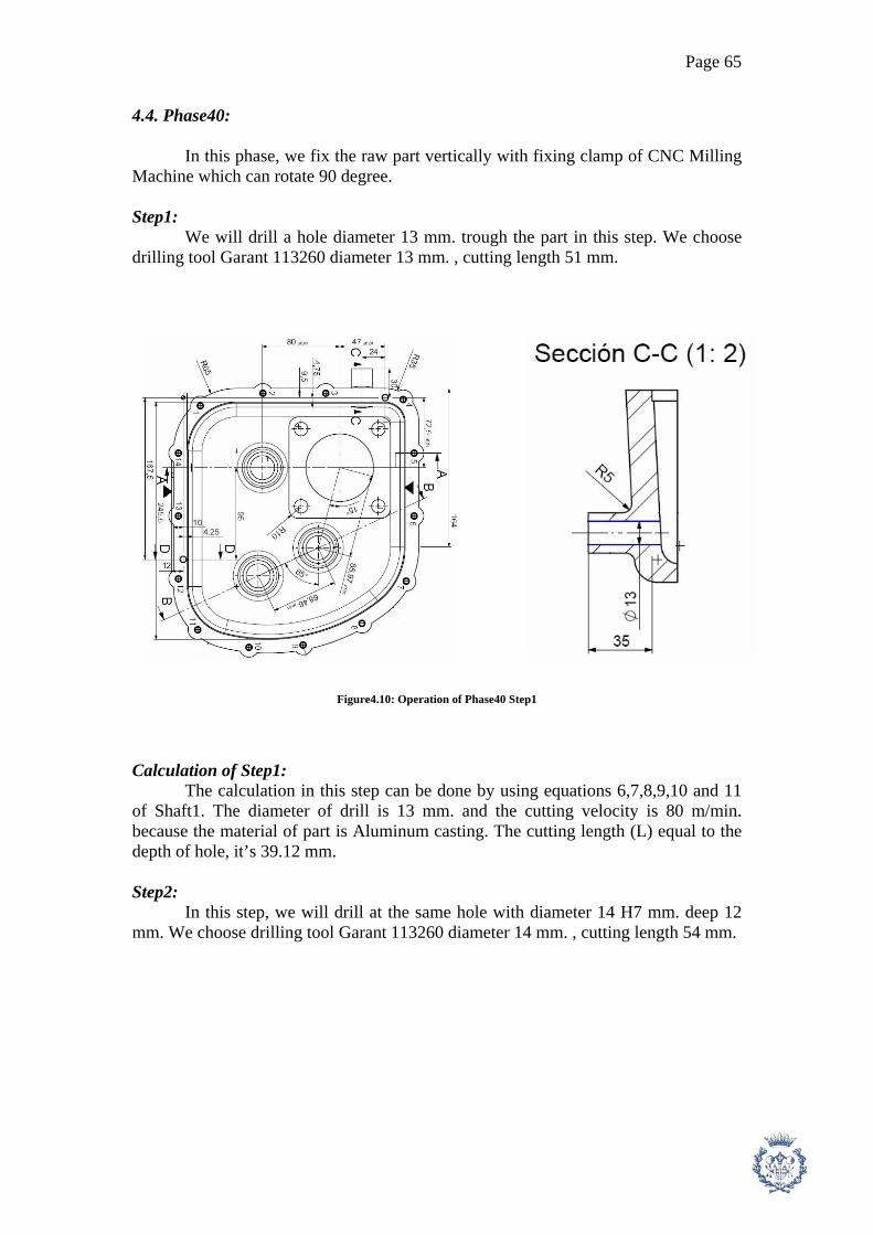
Page 65
4.4. Phase40:
In this phase, we fix the raw part vertically with fixing clamp of CNC Milling Machine which can rotate 90 degree. Step1: We will drill a hole diameter 13 mm. trough the part in this step. We choose drilling tool Garant 113260 diameter 13 mm. , cutting length 51 mm.
Figure4.10: Operation of Phase40 Step1
Calculation of Step1: The calculation in this step can be done by using equations 6,7,8,9,10 and 11 of Shaft1. The diameter of drill is 13 mm. and the cutting velocity is 80 m/min. because the material of part is Aluminum casting. The cutting length (L) equal to the depth of hole, it’s 39.12 mm. Step2: In this step, we will drill at the same hole with diameter 14 H7 mm. deep 12 mm. We choose drilling tool Garant 113260 diameter 14 mm. , cutting length 54 mm.

Page 66
Figure4.11: Operation of Phase40 Step2 Calculation of Step2: The calculation in this step can be done by using equations 6,7,8,9,10 and 11 of Shaft1. The diameter of drill is 14 mm. and the cutting velocity is 80 m/min. because the material of part is Aluminum casting. The cutting length is 12 mm. Step3: We will do back boring to have diameter 22 mm. in this step. We choose tool from Sandvik, the insert is CoroCut T-Max 4G and the tool holder is Q-Cut 151.3 . The operation in this step is quite complicate and it’s possible to be done since casting process if we increase diameter 22 mm. to be higher and avoid sharp edge.
Figure4.12: Operation of Phase40 Step3

Page 67
Calculation of Step3: In order to find advance speed, cutting force, cutting power, machine power and cutting time, we can use equations 15,16,17,18,19 and 20 of Shaft1. Step4: We turn the part 90 degree and drill a hole diameter 8.5 mm. through the part. We choose drilling tool Garant 113260 diameter 8.5 mm. Figure4.13: Operation of Phase40 Step4 Calculation of Step4: The calculation in this step can be done by using equations 6,7,8,9,10 and 11 of Shaft1. The diameter of drill is 8.5 mm. and the cutting velocity is 80 m/min. because the material of part is Aluminum casting. The cutting length is 5 mm. Step5: In this step, we will Tap M10 x 1.5 through the hole we drilled in the previous step. We use the tool Tap M10x1.5 Garant 131130. The suitable cutting speed (Vc) for internal tapping is 8 m/min and the advance speed (a) equal to pitch (1.5 in this case) Figure4.14: Operation of Phase40 Step5

Page 68
Calculation of Step5: The calculation in this process can be done by using the equation 28 and 29 of Shaft2.
Tool Data Step d(mm) az(mm.) Zt(teeth) n(rpm) av(mm/turn) Vam(mm/min) p(mm) b(mm)
1 13 1567 0.13 203.718 2 14 1455 0.14 203.718 3 12 0.025 3 3979 0.075 298.416 4.5 3
Step Fc(N) Pc(kW) Pm(kW) V(mm3/min) L(mm) tc(min) 1 147.9 0.148 0.211 39.118 0.192 2 171.5 0.172 0.245 12 0.059 3 2363 0.012 0.017 4028.609 28.274 0.095
Table4.3: Calculation data of Phase40

Page 69
4.5. Calculation of Cycle Time for Casing:
Phase Step Task tm (s)
tch (s)
tph (s)
tpre (s)
thmp (s)
tun (s)
20 1 Tool moves into part 2 5.271 Mill flat surface 213.1 Tool move out from the part 3 3.552 2 Tool moves into part 2 Drill 14 holes dia. 5 mm. 103.1 Tool move out from the part 3 2.577 3 Tool moves into part 2 Tap M6 deep 18 mm. 14 holes 35.63 Tool move out from the part 3 0.891 4 Tool moves into part 2 Drill 2 holes dia. 6 mm. 8.836 Tool move out from the part 3 0.221 5 Tool moves into part 2 Fine machining of 3 holes 1.948 Tool move out from the part 3 0.032 15 Total Time (s) 387.6 7.273 0 5.271 15 0 Cycle Time (s) 415.162
30 1 Tool moves into part 2 120 Mill flat surface 239.2 3.987
2 Fine machining at hole 70 mm. 78.96
Tool move out from the part 3 1.316 3 Tool moves into part 2 Drill 4 holes dia. 14 mm. 14.73 Tool move out from the part 3 0.368 15 Total Time (s) 342.9 5.671 120 0 15 0 Cycle Time (s) 483.578
40 1 Tool moves into part 2 120 Drill a hole dia. 13 mm. 11.52 Tool move out from the part 3 0.288 2 Tool moves into part 2
Drill dia.14 H7 mm deep 12 mm 3.534
Tool move out from the part 3 0.088 3 Tool moves into part 2 Back boring dia. 22 mm. 5.685 Tool move out from the part 3 0.095 4 Tool moves into part 2 Drill a hole dia. 8.5 mm. 1.473 Tool move out from the part 3 0.037 5 Tool moves into part 2 Tap M10 x 1.5 3.77 Tool move out from the part 3 0.094 15 Total Time (s) 50.98 0.602 120 0 15 0 Cycle Time (s) 186.585
Total Time (s) 781.5 13.55 240 5.271 45 0 Total Cycle Time (s) 1085.325
Table4.4: Cycle Time for casing

Page 70
5. Manufacturing Process of “Sliding part “
5.1. The raw material: In order to machine this part, we use the rectangular block of Bronze UNE C-3112 and it will be cut to the proper dimension in Phase10. It’s also possible to manufacture this part by Sintering Process instead of machining. Sintering is easier in this case but to employ it, we have to invest more machine for manufacture only 1 type of part. So we decide to do by machining. 5.2. Phase 10: The raw rectangular block of UNE C-3112 will be place at the Manual Saw Machine. It will be cut to have the dimension 19.5 x 23 x 32.5 mm. The calculation of this phase can be done in the same way as Shaft1 ( by using the method of milling machine ) and the results are shown in table5.1.
Figure5.1: Operation of Phase10
Tool Data Step d(mm) az(mm.) Zt(teeth) n(rpm) av(mm/turn) Vam(mm/min)
1 210 0.015 60 60.63 0.9 54.567
p(mm) b(mm) Fc(N) Pc(kW) Pm(kW) L(mm) tc(min) 32.5 2 81250 0.074 0.099 62 1.136
Table5.1: Calculation Data of Phase10

Page 71
5.3. Phase20:
We will use CNC Milling Machine in this phase. We fix the part at both sides horizontally with fixing clamp. Step1: In the first step, we will make flat surface with 1.5 mm. depth. We use milling tool Garant 181000 diameter 30 and long 30 mm. We choose tool’s diameter 30 mm. because the tool’s diameter has to cover the maximum thickness of the part which is 19.5 mm.
Figure5.2: Operation of Phase20 Step1 Calculation of Step1: Because the part is bronze and the milling tool is tungsten carbide, so the cutting velocity should be from 75-300 m/min [1]. The milling tool Garant 181000 has external diameter 30 mm. and number of teeth is 6. In order to find advance speed, cutting force, cutting power, machine power and cutting time, we can use equations 15,16,17,18,19 and 20 of Shaft1. In this operation, the cutting depth (p) is 1.5 mm for each cutting pass, the cutting width (b) is 19.5 mm. We can define the advance of teeth from table1.9. The suitable advance of teeth az = 0.005-0.025 mm.

Page 72
Step2: This step is the finishing operation (pocket operation). The part will have the same geometry as the final shape. We employ milling tool Garant 191200 , diameter 5 mm , cutting length 13 mm , number of teeth is 3. The diameter of milling tool must be not too big in order to have high precision.
Figure5.3: Operation of Phase20 Step2
Calculation of Step2: Because the part is bronze and the milling tool is tungsten carbide, so the cutting velocity should be from 75-300 m/min [1]. The milling tool Garant 191200 has external diameter 5 mm. and number of teeth is 3. In order to find advance speed, cutting force, cutting power, machine power and cutting time, we can use equations 15,16,17,18 and 19 of Shaft1. In this operation, the cutting depth (p) is 3 mm for each cutting pass, the cutting width (b) is 5 mm. This process is quite difficult to define the cutting length (L). In order to calculate the cutting time, we propose to calculate by the following equation. tc = Vc / V (31) Where: tc = total cutting time (min) Vc = Material volume to be cut (mm3) V = Volume cutting speed (mm3/min) The equation 31 base on the assumption that the movement of part is the shortest path. This assumption is possible in reality because we use Numerical control machine.

Page 73
Tool Data
Step d(mm) az(mm.) Zt(teeth) n(rpm) av(mm/turn) Vam(mm/min) p(mm) b(mm)1 30 0.025 6 848.8 0.15 127.324 1.5 19.5 2 5 0.025 3 5093 0.075 381.972 3 5
Step Fc(N) Pc(kW) Pm(kW) V(mm^3/min) Vc(mm3) L(mm) tc(min) 1 36563 0.078 0.111 3724.226 32.5 0.255 2 18750 0.119 0.171 5729.578 6240.493 1.089
Table5.2: Calculation Data of Phase20
5.4. Phase30: Now we change the machining surface to another face and fix the part at both sides horizontally with clamp.
Figure5.4: Operation of Phase30 Step1
Step1: This step is the finishing operation (pocket operation) of the other side of part. The part will have the same geometry as the final shape. We employ milling tool Garant 191200 , diameter 5 mm , cutting length 13 mm , number of teeth is 3. The diameter of milling tool must be not too big in order to have high precision. Calculation of Step1: Because the part is bronze and the milling tool is tungsten carbide, so the cutting velocity should be from 75-300 m/min [1]. The milling tool Garant 191200 has external diameter 5 mm. and number of teeth is 3. In order to find advance speed, cutting force, cutting power, machine power and cutting time, we can use equations 15,16,17,18,19 and 31 of Shaft1. In this

Page 74
operation, the cutting depth (p) is 3 mm for each cutting pass, the cutting width (b) is 5 mm.
Tool Data Step d(mm) az(mm.) Zt(teeth) n(rpm) av(mm/turn) Vam(mm/min) p(mm) b(mm)
1 5 0.025 3 5093 0.075 381.972 3 5
Step Fc(N) Pc(kW) Pm(kW) V(mm3/min) Vc(mm3) tc(min) 1 18750 0.119 0.171 5729.578 2242.5 0.391
Table5.3: Calculation Data of Phase30
5.5. Calculation of Cycle Time for Sliding part:
Phase Step Task tm (s)
tch (s)
tph (s)
tpre (s)
thmp (s)
tun (s)
10 1 Cut raw part by Saw Machine 68.16 0.439 15 Cycle Time (s) 83.599
20 1 Tool moves into part 2 120 5.271 Mill flat surface 15.32 Tool move out from the part 3 0.255 2 Tool moves into part 2 Finish machining 65.35 Tool move out from the part 3 1.089 15 Total Time (s) 90.67 1.344 120 5.271 15 0 Cycle Time (s) 232.281
30 1 Tool moves into part 2 120 Finish machining 23.46 Tool move out from the part 3 0.391 15 Total Time (s) 28.46 0.391 120 0 15 0 Cycle Time (s) 163.851
Total Time (s) 187.3 1.735 240 5.710 45 0 Total Cycle Time (s) 479.731
Table5.4: Cycle Time for Sliding part

Page 75
6. Manufacturing Process of “ Clutch Fork “
6.1. The raw material: The raw material for Clutch Fork is from forging process. The dimension is similar to the final shape. We decide to get raw material from forging because this kind of shape is not suitable to be machined from steel block, we will loose too much material. It’s possible to use casting process, but the part will have low flexion resistance which is the important mechanical property of the part. 6.2. Phase20: We fix the raw part horizontally with fixing clamp of CNC Milling Machine. Step1: In this step, we will take out some material at the clutch legs 2 positions with 0.43 mm. depth and 15 mm. length. We use milling tool Garant 191080 diameter 10 mm. , cutting length 22 mm. and number of teeth is 2. The cutting length of the tool (22 mm.) must longer than the length of clutch legs (15 mm.) because would like to machine only 1 pass.
Figure6.1: Operation of Phase20 Step1 Calculation of Step1: Because the part is Alloy Steel and the milling tool is tungsten carbide, so the cutting velocity should be from 150 m/min [1]. In order to find advance speed, cutting force, cutting power, machine power and cutting time, we can use equations 15,16,17,18,19 and 20 of Shaft1. In this operation, the cutting depth (p) is 0.43 mm, the cutting width (b) is 15 mm. The cutting length (L) is 30 mm.

Page 76
We can define the advance of teeth from table1.9. The material we have to machine is Steel 600-700 N/mm2, so the suitable Advance of teeth az = 0.005-0.015 mm. Step2: In this step, we will drill a hole diameter 3.3 mm. and deep 4.5 mm. (+1, -0 mm. tolerance). This hole is to prepare for the next tapping process. We use the drill Garant 113260 diameter 3.3 mm.
Figure6.2: Operation of Phase20 Step2 Calculation of Step2: The calculation in this step can be done by using equations 6,7,8,9,10 and 11 of Shaft1. The diameter of drill is 3.3 mm. and the cutting velocity is 20 m/min. because the material of part is Alloy Steel. The total cutting length (L) is 4.5 mm. Step3: In this step, we will tap M4 x 0.7 , deep 4 mm. (+1, -0 mm. tolerance) at the hole in Step2. We use tap Garant 131130 M4 x 0.7 , total length 63 mm. The suitable cutting speed (Vc) for internal tapping is 8 m/min and the advance speed (a) equal to pitch (0.7 in this case)
Figure6.3: Operation of Phase20 Step3

Page 77
Calculation of Step3: The calculation in this process can be done by using the equation 28 and 29 of Shaft2. The rotation speed can be found by using equation 1 and the advance speed is fix at pitch mm/turn.
Tool Data Step d(mm) az(mm.) Zt(teeth) n(rpm) av(mm/turn) Vam(mm/min) p(mm) b(mm)
1 10 0.015 2 4775 0.03 143.239 0.43 15 2 3.3 1543 0.033 50.93 3 4 636.6 0.7 445.634
Step Fc(N) Pc(kW) Pm(kW) V(mm3/min) L(mm) tc(min) 1 19350 0.046 0.066 923.894 30 0.209 2 163.4 0.163 0.233 4.5 0.088 3 4 0.009
Table6.1: Calculation data of Phase20
6.3. Phase30: The Clutch Fork’s shape is quite difficult to be fixed vertically. We have to design special shape fixing plate for it. We fix the raw part with the special shape fixing plate, then fix them vertically with the fixing clamp of CNC Milling Machine. Step1: In this step, we will drill 2 holes, diameter 8 H11 mm. and diameter 8 H8 mm through the part. We use the drill Garant 113260 diameter 8 mm.
Figure6.4: Operation of Phase30 Step1

Page 78
Calculation of Step1: The calculation in this step can be done by using equations 6,7,8,9,10 and 11 of Shaft1. The diameter of drill is 8 mm. and the cutting velocity is 20 m/min. because the material of part is Alloy Steel. The total cutting length (L) is the summation of the depth of the 2 holes, so L is 15 mm.
Tool Data Step d(mm) az(mm.) Zt(teeth) n(rpm) av(mm/turn) Vam(mm/min) p(mm) b(mm)
1 8 636.6 0.08 50.93
Step Fc(N) Pc(kW) Pm(kW) V(mm3/min) L(mm) tc(min) 1 960 0.128 0.183 15 0.295
Table6.2: Calculation data of Phase30
6.4. Phase40: In this phase, we will do at the other side of part. We turn the part 180 degree and fix the raw part with the special shape fixing plate, then fix them vertically with the fixing clamp of CNC Milling Machine. Step1: In this step, we will drill a hole diameter 8 H8 mm. through the part. We use the drill Garant 113260 diameter 8 mm.
Figure6.5: Operation of Phase30 Step1 Calculation of Step1: The calculation in this step can be done by using equations 6,7,8,9,10 and 11 of Shaft1. The diameter of drill is 8 mm. and the cutting velocity is 20 m/min. because the material of part is Alloy Steel. The total cutting length (L) is 7.5 mm.

Page 79
Tool Data Step d(mm) az(mm.) Zt(teeth) n(rpm) av(mm/turn) Vam(mm/min) p(mm) b(mm)
1 8 636.6 0.08 50.93
Step Fc(N) Pc(kW) Pm(kW) V(mm3/min) L(mm) tc(min) 1 960 0.128 0.183 7.5 0.147
Table6.3: Calculation data of Phase40
6.5. Phase50: This phase is the heat treatment process. We will do heat treatment at the external dia 50 mm. to have the hardness 46-48 HRC ( 1mm. depth). The part will be heated by Induction heating and the time required for the process is 30 min/lot ( 1 lot contains 20 parts) or 1.5 min/part ( This operation will be done by the external company).
6.6. Calculation of Cycle Time for Clutch Fork:
Phase Step Task tm (s)
tch (s)
tph (s)
tpre (s)
thmp (s)
tun (s)
20 1 Tool moves into part 2 5.271 Mill at 2 clutch legs 12.57 Tool move out from the part 3 0.209 2 Tool moves into part 2 Drill a hole dia. 3.3 mm. 5.301 Tool move out from the part 3 0.133 3 Tool moves into part 2 Tap M4 deep 4 mm. 0.539 Tool move out from the part 3 0.013 15 Total Time (s) 33.41 0.355 0 5.271 15 0 Cycle Time (s) 54.033
30 1 Tool moves into part 2 120 Drill 2 holes dia. 8 mm. 17.7 Tool move out from the part 3 0.443 Total Time (s) 22.7 0.443 120 0 0 0 Cycle Time (s) 143.143
40 1 Tool moves into part 2 120 Drill 1 hole dia. 8 mm. 8.82 Tool move out from the part 3 0.221 15 Total Time (s) 13.82 0.221 120 0 15 0 Cycle Time (s) 149.041
80 1 Heat treatment 90 Total Time (s) 69.93 1.018 240 5.271 30 90 Total Cycle Time (s) 436.216
Table6.4: Cycle Time for Clutch Fork

Page 80
7. Manufacturing Process of “ Pin “
7.1. The raw material: Cylindrical Bar Dia 12 f6 mm. In order to machine this part, we use cylindrical bar steel 37 Cr 4 with diameter 12 f6 mm. The cylindrical bar steel diameter 12 f6 mm is existed in the market, so we don’t need to use cylindrical bar steel diameter 15 mm. and do finishing operation. 7.2. Phase 10: The cylindrical bars usually come with the long length shape. To be suitable for the Lathe Machine, the bars have to be cut by Manual Disc Saw Machine. The total distance of the final shape is 85 mm., we have to add 1.5 mm. for the both end of bar to be machine in Finishing Operation. So we have to cut the bar to have the length 88 mm. with the tolerance +1, -0 mm. The calculation of this phase can be done in the same way as Shaft1 ( by using the method of milling machine ) and the results are shown in table7.1.
Figure7.1: Operation of Phase10
Tool Data Step d(mm) az(mm.) Zt(teeth) n(rpm) av(mm/turn) Vam(mm/min)
1 210 0.015 60 60.63 0.9 54.567
p(mm) b(mm) Fc(N) Pc(kW) Pm(kW) L(mm) tc(min) 12 2 43200 0.039 0.052 12 0.22
Table7.1: Calculation data of Phase10
7.3. Phase20: We employ CNC Lathe Machine in this phase. We fix the raw part at one end by fixing plate with hard jaws of CNC Lathe Machine. Step1:
We start machining the part by taking out front surface. In this operation, we employ Stellram cutting tool SNMG120408E-3G with the holder MSKNR/L-124B [2]. The tool insert SNMG120408E-3G is square shape which is suitable for

Page 81
machining front surface and rough machining. The tool is Right hand tool because we fix the part with Lathe Machine on the left.
Figure7.2: Operation of Phase20 Step1 Calculation of Step1:
The calculation in this step is similar to the one of Shaft1 Phase20 Step1. The only difference is the average diameter of the shaft, in this shaft d = (12+0)/2 = 6 mm. We can calculate by utilizing the equations 1,2,3,4,5,6 and 7 of Shaft1. Step2: This step is to machine finishing surface to have diameter 8 h7 mm. length 7.5 mm. at the end of part. We use Stellram tool insert DNMG150408E-3G and tool holder MDJNR/L-124B, right hand.
Figure7.3: Operation of Phase20 Step2 Calculation of Step2: In order to calculate rotation speed (n), advance speed (a), cutting force (Fc), cutting power (Pc), machine power (Pm), cutting time (tc) and advance velocity (Va), all can be calculate by the equations 1,2,3,4,5,6 and 7. In this step, we use the average diameter to calculate the rotation speed as we have said in the calculation of phase20 step1 and we use Vc for finishing surface with carbide tool (see table1.2). The rotation speed we obtain from calculation will be very high because of the diameter of bar is very small. We should limit the maximum rotation speed in order to protect machine from damage. In this process, we limit at 3000 rpm. The cutting length (L) in this step is the summation of the movement of part, we find L = 7.5 mm.

Page 82
Step rp(mm) d(mm) n (rpm) p(mm) Ra(mm) a(mm/turn) S(mm2) Fc(N)1 0.031 6 3000 1.5 1.6 0.045 0.067 120 2 0.031 10 3000 2 1.6 0.045 0.089 160
Step Pc(kW) Pm (kW) L (mm) Va(mm/min) tc(min)
1 0.301 0.401 6 133.626 0.045 2 0.401 0.535 7.5 133.626 0.056
Table7.2: Calculation data of Phase20
7.4. Phase30:
We are still at CNC Lathe Machine. We fix the raw part at another end by fixing plate with soft jaws of CNC Lathe Machine. Step1:
We take out front surface. In this operation, we employ Stellram cutting tool SNMG120408E-3G with the holder MSKNR/L-124B [2]. The tool insert SNMG120408E-3G is square shape which is suitable for machining front surface and rough machining. The tool is Right hand tool because we fix the part with Lathe Machine on the left.
Figure7.4: Operation of Phase30 Step1 Calculation of Step1: It’s exactly the same as Phase20 step1 of this part. Step2: This step is to machine finishing surface to have diameter 10 h7 mm. length 20.5 mm. at the end of part. We use Stellram tool insert DNMG150408E-3G and tool holder MDJNR/L-124B, right hand.

Page 83
Figure7.5: Operation of Phase30 Step2 Calculation of Step2: In order to calculate rotation speed (n), advance speed (a), cutting force (Fc), cutting power (Pc), machine power (Pm), cutting time (tc) and advance velocity (Va), all can be calculate by the equations 1,2,3,4,5,6 and 7. In this step, we use the average diameter to calculate the rotation speed as we have said in the calculation of phase20 step1 and we use Vc for finishing surface with carbide tool (see table1.2). The rotation speed we obtain from calculation will be very high because of the diameter of bar is very small. We should limit the maximum rotation speed in order to protect machine from damage. In this process, we limit at 3000 rpm. The cutting length (L) in this step is the summation of the movement of part, we find L = 20.5 mm.
Step rp(mm) d(mm) n (rpm) p(mm) Ra(mm) a(mm/turn) S(mm2) Fc(N)1 0.031 6 3000 1.5 1.6 0.045 0.067 120 2 0.031 11 3000 1 1.6 0.045 0.045 80.2
Step Pc(kW) Pm (kW) L (mm) Va(mm/min) tc(min)
1 0.301 0.401 6 133.626 0.045 2 0.2 0.267 20.5 133.626 0.153
Table7.3: Calculation data of Phase30
7.5. Phase40: In this phase, we move to CNC Milling Machine. We fix the part by Index plate with soft jaws. Step1: In this step, we will drill a 120 degree hole at diameter 10 h7 mm. end. We use drill Garant 112110 , 120 degree , diameter 5 mm.

Page 84
Figure7.6: Operation of Phase40 Step1 Calculation of Step1: The calculation of this step can be done by follow the method and formula in Phase20 Step2 of Shaft1. We use the diameter 5 mm. and the depth 1 mm. The total cutting length equal to the depth. Step2: In this step, we will drill a 120 degree hole at diameter 8 h7 mm. end. We use drill Garant 112110 , 120 degree , diameter 5 mm.
Figure7.7: Operation of Phase40 Step2 Calculation of Step2: The calculation of this step can be done by follow the method and formula in Phase20 Step2 of Shaft1. We use the diameter 5 mm. and the depth 1 mm. The total cutting length is equal to the depth.
Tool Data Step d(mm) az(mm.) Zt(teeth) n(rpm) av(mm/turn) Vam(mm/min) p(mm) b(mm)
1 5 1273 0.05 63.662 2 5 1273 0.05 63.662
Step Fc(N) Pc(kW) Pm(kW) V(mm3/min) L(mm) tc(min) 1 225 0.038 0.054 1 0.016 2 225 0.038 0.054 1 0.016
Table7.4: Calculation data of Phase40

Page 85
7.6. Phase50: This phase is the heat treatment process. We will do heat treatment at the external dia 50 mm. to have the hardness 46-48 HRC ( 1mm. depth). The part will be heated by Induction heating and the time required for the process is 30 min/lot ( 1 lot contains 20 parts) or 1.5 min/part ( This operation will be done by the external company). . 7.7. Calculation of Cycle Time for Pin:
Phase Step Task tm (s)
tch (s)
tph (s)
tpre (s)
thmp (s)
tun (s)
10 1 Cut the part 13.19 0.439 15 Cycle Time (s) 28.634
20 1 Tool moves into part 2 5.271 Frontal machining 2.694 Tool move out from the part 3 0.045 2 Tool moves into part 2 Finish surface machining 3.368 Tool move out from the part 3 0.056 15 Total Time (s) 16.06 0.101 0 5.271 15 0 Cycle Time (s) 36.434
30 1 Tool moves into part 2 120 Frontal machining 2.694 Tool move out from the part 3 0.045 2 Tool moves into part 2 Finish surface machining 9.205 Tool move out from the part 3 0.153 15 Total Time (s) 21.9 0.198 120 0 15 0 Cycle Time (s) 157.097
40 1 Tool moves into part 2 5.271 Drill a hole at section B-B 0.96 0.024 2 Drill a hole at section A-A 0.96 Tool move out from the part 3 0.024 15 Total Time (s) 6.92 0.048 0 5.271 15 0 Cycle Time (s) 27.239
50 1 Heat treatment 90 Total Time (s) 58.08 0.347 120 10.981 60 90 Total Cycle Time (s) 339.403
Table7.5: Cycle Time for Pin

Page 86
8. Manufacturing Process of “ Sealing Plate 1-2 “ 8.1. The raw material: The raw part of this process is UNE 38212L-212 (Aluminum casting) from casting. The casting part has the shape similar to the final shape. The part has to be machined in several steps by Milling Machine. 8.2. Phase10: We fix the raw part horizontally with fixing clamp of CNC Milling Machine. Step1: The purpose of this step is to make flat machining at the part with the cutting depth 1.5 mm. We use milling tool Garant 181000 diameter 50 mm , thickness 30 mm. and number of teeth is 6. We choose tool’s diameter 50 mm. which is more than half of the maximum width of part (45 mm.) in order to machine only 2 passes.
Figure8.1: Operation of Phase10 Step1 Calculation of Step1: Because the part is casting aluminum and the milling tool is tungsten carbide, so the cutting velocity should be from 75-300 m/min [1]. The milling tool Garant 181000 has external diameter 50 mm. and number of teeth is 6. In order to find advance speed, cutting force, cutting power, machine power and cutting time, we can use equations 15,16,17,18,19 and 20 of Shaft1. In this operation, the cutting depth (p) is 1.5 mm, the cutting width (b) is 45 mm. ( equal to half of maximum width of part). The cutting length (L) is the summation of 2 passes which is L = 342.5 mm. We can define the advance of teeth from table1.9. The material we have to machine is Aluminum 100 N/mm2, so the suitable Advance of teeth az = 0.005-0.025 mm.
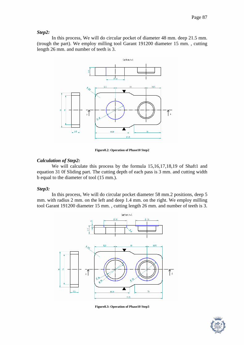
Page 87
Step2: In this process, We will do circular pocket of diameter 48 mm. deep 21.5 mm. (trough the part). We employ milling tool Garant 191200 diameter 15 mm. , cutting length 26 mm. and number of teeth is 3.
Figure8.2: Operation of Phase10 Step2 Calculation of Step2: We will calculate this process by the formula 15,16,17,18,19 of Shaft1 and equation 31 0f Sliding part. The cutting depth of each pass is 3 mm. and cutting width b equal to the diameter of tool (15 mm.). Step3: In this process, We will do circular pocket diameter 58 mm.2 positions, deep 5 mm. with radius 2 mm. on the left and deep 1.4 mm. on the right. We employ milling tool Garant 191200 diameter 15 mm. , cutting length 26 mm. and number of teeth is 3.
Figure8.3: Operation of Phase10 Step3

Page 88
Calculation of Step3: We can proceed the calculation for this step by the same manner as Step2 of this part. The cutting depth is still 3 mm. and cutting width b equal to the diameter of tool (15 mm.). Step4: In this process, We will do circular pocket diameter 75 mm. and deep 2 mm. We employ milling tool Garant 191200 diameter 15 mm. , cutting length 26 mm. and number of teeth is 3.
Figure8.4: Operation of Phase10 Step4 Calculation of Step4: We can proceed the calculation for this step by the same manner as Step2. The cutting depth is 2 mm. and cutting width b equal to the diameter of tool (15 mm.).
Tool Data Step d(mm) az(mm.) Zt(teeth) n(rpm) av(mm/turn) Vam(mm/min) p(mm) b(mm) Fc(N)
1 50 0.025 6 954.9 0.15 143.239 1.5 45 843752 15 0.025 3 3183 0.075 238.732 3 15 562503 15 0.025 3 3183 0.075 238.732 3 15 562504 15 0.025 3 3183 0.075 238.732 2 15 37500
Step Pc(kW) Pm(kW) V(mm3/min) Vc(mm3) L(mm) tc(min) 1 0.201 0.288 9668.663 342.5 2.391 2 0.224 0.32 10742.959 38905.48 3.621 3 0.224 0.32 10742.959 16909.308 1.574 4 0.149 0.213 7161.972 8835.729 1.234
Table8.1: Calculation data of Phase10

Page 89
8.3. Phase20: In this phase, we are still with CNC Milling Machine. We change the machining surface to the another face and fix the part at both sides horizontally. Step1: In this process, We will do circular pocket diameter 55 H11 mm. deep 12.5 mm. We employ milling tool Garant 191200 diameter 15 mm. , cutting length 26 mm. and number of teeth is 3.
Figure8.5: Operation of Phase20 Step1 Calculation of Step1: We can proceed the calculation for this step by the same manner as Step2 of this part. The cutting depth is 3 mm. and cutting width b equal to the diameter of tool (15 mm.). Step2: In this process, We will do Grooving diameter 58 mm. deep 2.15 mm. We employ milling tool Garant 185500 diameter 50 mm. , thick 2 mm. , number of teeth is 22. The diameter of tool (50 mm.) has to be smaller than the diameter of part (55 mm.) because tool will enter into the part at the center of hole until it arrives the machining position and then make a groove.

Page 90
Figure8.6: Operation of Phase20 Step2 Calculation of Step2: In order to find advance speed, cutting force, cutting power, machine power and cutting time, we can use equations 15,16,17,18,19 and 20 of Shaft1. In this operation, the cutting depth (p) is 1.5 mm, the cutting width (b) is 2 mm. ( equal to the thickness of tool ).
The cutting length (L) is the perimeter of the movement of tool (circular shape). The diameter of the movement of tool is 8 mm, so the cutting length (L) is 25.13 mm. Step3: In this step, we will mill the space for the head of bolts, the depth is 7.5 mm. and the radius is 10 mm, 6 positions. We use milling tool Garant 191200 diameter 15 mm. , cutting length 22 mm. and number of teeth is 3.
Figure8.7: Operation of Phase20 Step3

Page 91
Calculation of Step3: We can proceed the calculation for this step by the same manner as Step2. The cutting depth is 3 mm. and cutting width b equal to the diameter of tool (15 mm.). In order to calculate the cutting volume (Vc), We use the true scale drawing to define the cutting volume (Vc) ( See Figure7.1). We found the cutting volume (Vc) is:
Vc = ( 2 * ( 235.635 + 318 + 451.26 ) ) * 7.5 = 15073.425 mm^3
Figure8.8: Drawing for cutting volume calculation
Step4: In this step, we will drill 6 holes diameter 6 mm and deep 14 mm. We use the drilling tool Garant 113260 diameter 6 mm.
Figure8.9: Operation of Phase20 Step4

Page 92
Calculation of Step4: The calculation in this step can be done by using equations 6,7,8,9,10 and 11 of Shaft1. The diameter of drill is 6 mm. and the cutting velocity is 70 m/min. because the material of part is Aluminum casting. The depth of each hole is 14 mm. so the total cutting length (L) is 84 mm.
Tool Data Step d(mm) az(mm.) Zt(teeth) n(rpm) av(mm/turn) Vam(mm/min) p(mm) b(mm) Fc(N)
1 15 0.025 3 3183 0.075 238.732 3 15 562502 50 0.025 22 954.9 0.55 525.211 1.5 2 3750 3 10 0.025 3 4775 0.075 358.099 3 10 375004 6 2971 0.06 178.254 225
Step Pc(kW) Pm(kW) V(mm3/min) Vc(mm3) L(mm) tc(min) 1 0.224 0.32 10742.959 29697.868 2.764 2 0.033 0.047 1575.634 25.133 0.048 3 0.224 0.32 10742.959 15073.425 1.403 4 0.225 0.321 84 0.471
Table8.2: Calculation data of Phase20

Page 93
8.4. Calculation of Cycle Time for Sealing plate 1-2:
Phase Step Task tm (s)
tch (s)
tph (s)
tpre (s)
thmp (s)
tun (s)
10 1 Tool moves into part 2 5.271 Mill flat surface 143.5 Tool move out from the part 3 2.391 2 Tool moves into part 2 Circular pocket Dia 48 mm. 217.3 3.621 3 Circular pocket Dia 58 mm. 94.44 1.574 4 Circular pocket Dia 75 mm. 74.02 Tool move out from the part 3 1.234 15 Total Time (s) 539.2 8.82 0 5.271 15 0 Cycle Time (s) 568.308
20 1 Tool moves into part 2 120
Circular pocket Dia 55 H11 mm 165.9
Tool move out from the part 3 2.764 2 Tool moves into part 2 Grooving of Dia 58 mm. 2.871 Tool move out from the part 3 0.048 3 Tool moves into part 2
Mill the space for head of bolts 84.19
Tool move out from the part 3 1.403 4 Tool moves into part 2 Drill 6 holes dia. 6 mm 28.27 Tool move out from the part 3 0.707 15 Total Time (s) 301.2 4.922 120 0 15 0 Cycle Time (s) 441.118
Total Time (s) 840.4 13.74 120 5.271 30 0 Total Cycle Time (s) 1009.426
Table8.3: Cycle time for Sealing plate1-2

Page 94
9. Manufacturing Process of “ Transmission Plate 2 “
9.1. The raw material: The raw material for Transmission Plate is from forging process. The dimension is similar to the final shape. We decide to get raw material from forging because this kind of shape is not suitable to be machined from steel bar, we will loose too much material. 9.2. Phase20: We use CNC Lathe Machine for this phase. We fix the raw part at external diameter 45 mm. by fixing plate with hard jaws of CNC Lathe Machine. Step1: In the first step, we take out front material 1.5 mm. at the diameter 93 mm. In this operation, we employ Stellram cutting tool SNMG120408E-3G with the holder MSKNR/L-124B [2]. The tool insert SNMG120408E-3G is square shape which is suitable for machining front surface and rough machining. The tool is Right hand tool because we fix the part with Lathe Machine on the left
Figure9.1: Operation of Phase20 Step1 Calculation of Step1: The calculation in this step is similar to the one of Shaft1 Phase20 Step1. The only difference is the average diameter of the machining position to calculate the rotation speed, in this case d = (93 + 29) / 2 = 61 mm. We can calculate by utilizing the equations 1,2,3,4,5,6 and 7 of Shaft1. Step2: In this step we will do the boring operation. We Bore to have a hole with diameter 47 mm. length 2.3 mm. and diameter 42 mm. length 10.8 mm. and diameter 32 through the part with chamfer 2 x 30 degree at diameter 32 mm. We use cutting tool WBGW1.21_ (kyocera) with the tool holder S10H-SWUBR06-06 [3].

Page 95
Figure9.2: Operation of Phase20 Step2 Calculation of Step2: The calculation in this step is similar to the one of Shaft1 Phase20 Step1. We can calculate by utilizing the equations 1,2,3,4,5,6 and 7 of Shaft1. The average diameter to calculate rotation speed is d = ( 47 + 42 + 32 ) / 3 = 40.33 mm. The edge radius of tool is rp = 0.2 mm [3]. The total cutting length (L) is the summation of tool’s movement, L = ( 1 * 45.5 ) + ( 2 * 13.1 ) + ( 1 * 2.3 ) = 74 mm. Step3: In this step, we will do the finishing of the external surface. We use Stellram tool insert DNMG150408E-3G and tool holder MDJNR/L-124B, right hand.
Figure9.3: Operation of Phase20 Step3 Calculation of Step3: In order to calculate rotation speed (n), advance speed (a), cutting force (Fc), cutting power (Pc), machine power (Pm), cutting time (tc) and advance velocity (Va), all can be calculate by the equations 1,2,3,4,5,6 and 7. In this step, we use the average diameter to calculate the rotation speed as we have said in the calculation of phase20 step1 and we use Vc for finishing surface with carbide tool (see table1.2).

Page 96
The cutting length (L) in this step is the movement of part, we find L = 7.5 mm.
Step rp(mm) d(mm) n (rpm) p(mm) Ra(mm) a(mm/turn) S(mm2) Fc(N)1 0.031 61 782.7 1.5 1.6 0.045 0.067 80.2 2 0.2 40.333 1421 3 1.6 0.113 0.339 407 3 0.031 90 636.6 1.5 1.6 0.045 0.067 80.2
Step Pc(kW) Pm (kW) L (mm) Va(mm/min) tc(min)
1 0.2 0.267 32 34.864 0.918 2 1.222 1.629 74 160.718 0.46 3 0.241 0.321 7.5 28.356 0.264
Table9.1: Calculation data of Phase20
9.3. Phase30: In this phase, we will machine the other side of part. We fix the raw part at internal diameter 42 mm. with soft jaws of CNC Lathe Machine. Step1: In this step, we take out front material 1.5 mm. at the diameter 53 mm. In this operation, we employ Stellram cutting tool SNMG120408E-3G with the holder MSKNR/L-124B [2]. The tool insert SNMG120408E-3G is square shape which is suitable for machining front surface and rough machining. The tool is Right hand tool because we fix the part with Lathe Machine on the left
Figure9.4: Operation of Phase30 Step1 Calculation of Step1: The calculation in this step is similar to the one of Shaft1 Phase20 Step1. The only difference is the average diameter of the machining position to calculate the rotation speed, in this case d = (48 + 32) / 2 = 40 mm. We can calculate by utilizing the equations 1,2,3,4,5,6 and 7 of Shaft1.

Page 97
Step2: In this step we will do the boring operation. We Bore to have a hole with diameter 36 mm. length 11.9 mm. with chamfer 2 x 30 degree at diameter 32 mm. We use cutting tool WBGW1.21_ (kyocera) with the tool holder S10H-SWUBR06-06 [3].
Figure9.5: Operation of Phase30 Step2 Calculation of Step2: The calculation in this step is similar to the one of Shaft1 Phase20 Step1. We can calculate by utilizing the equations 1,2,3,4,5,6 and 7 of Shaft1. The average diameter to calculate rotation speed is d = 36 mm. The edge radius of tool is rp = 0.2 mm [3]. The total cutting length (L) is the summation of tool’s movement, L = 11.9 mm. Step3: In this step, we will do the finishing of the external surface. We use Stellram tool insert DNMG150408E-3G and tool holder MDJNR/L-124B, right hand.
Figure9.6: Operation of Phase30 Step3
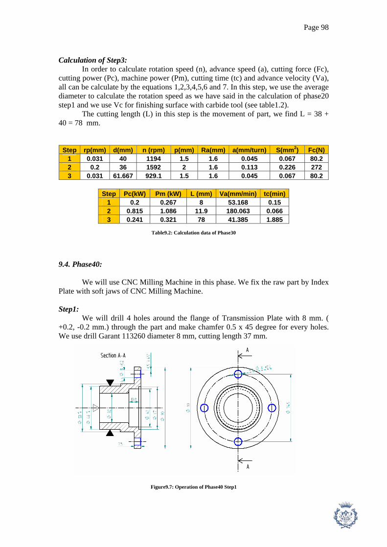
Page 98
Calculation of Step3: In order to calculate rotation speed (n), advance speed (a), cutting force (Fc), cutting power (Pc), machine power (Pm), cutting time (tc) and advance velocity (Va), all can be calculate by the equations 1,2,3,4,5,6 and 7. In this step, we use the average diameter to calculate the rotation speed as we have said in the calculation of phase20 step1 and we use Vc for finishing surface with carbide tool (see table1.2). The cutting length (L) in this step is the movement of part, we find L = 38 + 40 = 78 mm.
Step rp(mm) d(mm) n (rpm) p(mm) Ra(mm) a(mm/turn) S(mm2) Fc(N)1 0.031 40 1194 1.5 1.6 0.045 0.067 80.2 2 0.2 36 1592 2 1.6 0.113 0.226 272 3 0.031 61.667 929.1 1.5 1.6 0.045 0.067 80.2
Step Pc(kW) Pm (kW) L (mm) Va(mm/min) tc(min)
1 0.2 0.267 8 53.168 0.15 2 0.815 1.086 11.9 180.063 0.066 3 0.241 0.321 78 41.385 1.885
Table9.2: Calculation data of Phase30
9.4. Phase40: We will use CNC Milling Machine in this phase. We fix the raw part by Index Plate with soft jaws of CNC Milling Machine. Step1: We will drill 4 holes around the flange of Transmission Plate with 8 mm. ( +0.2, -0.2 mm.) through the part and make chamfer 0.5 x 45 degree for every holes. We use drill Garant 113260 diameter 8 mm, cutting length 37 mm.
Figure9.7: Operation of Phase40 Step1

Page 99
Calculation of Step1: The calculation in this step can be done by using equations 6,7,8,9,10 and 11 of Shaft1. The diameter of drill is 8 mm. and the cutting velocity is 80 m/min. because the material of part is Aluminum casting. The depth of each hole is 7.5 mm. so the total cutting length (L) is 30 mm.
Tool Data Step d(mm) az(mm.) Zt(teeth) n(rpm) av(mm/turn) Vam(mm/min) p(mm) b(mm)
1 8 795.8 0.08 63.662
Step Fc(N) Pc(kW) Pm(kW) V(mm3/min) L(mm) tc(min) 1 384 0.064 0.091 30 0.471
Table9.3: Calculation data of Phase40
9.5. Phase50: In this phase, we will make the internal gear by Broaching Machine because the internal diameter is too small to do this operation by Milling Machine. We fix the part at the external diameter 45 mm. by fixing plate with soft jaws of Broaching Machine. Step1: This step is to make Internal Gear according to DIN 5462 32x36x6. This process will be done by Broaching Machine. The tool we use in this process is the tool for Gear shape32x36x6.
Figure9.8: Operation of Phase50 Step1

Page 100
Calculation of Step1: We will start the calculations with the tool data. The pitch of tool (p) can be calculated by the following formula[6]. p = 1.75 * sqrt(L) (32) Where: p = pitch of tool (mm.) L = Total length to broach (mm.) Then we have to find the number of teeth (z) necessary for this process. The calculation can be done by the following formula [6]. z = ( (di – df)/2 ) / r’ (33) Where: z = number of teeth necessary for the process di = The initial diameter of the part before broaching (mm.) df = The final diameter of part after broaching (mm.) r’ = The progression of the height of tool teeth (mm.) In fact, the number of teeth (z) necessary for the process is not real number of tool’s teeth because it’s enough for the rough machining only. We have to add more teeth for finishing surface as well. The formula is shown below [6]. zt = z + za (34) Where: zt = The total (real) number of teeth za = Number of teeth for finishing surface In this case, we use za = 5 Now we can calculate the Cutting power (Fc) for broaching process. The formula is shown below [6]. Fc = σt * k * S* zw (35) zw = L / p (36) Where: k = constant depending on the type of material k = 3 for elastic material k = 5 for less or non elastic material (ex. Casting ) σt = Resistant of traction stress of material (N/mm2) S = Cutting surface of the part (mm2) , see details in Figure8.9 zw = The number of teeth to be machined in each moment. p = pitch of tool (mm.) L = Total length to broach (mm.)

Page 101
Figure9.9: The cutting surface of part in Broaching Process From Figure8.9, we define the cutting surface is the part’s material to be cut at each moment, so the depth of the surface equal to the progression of the height of tool teeth (r’). We found that :
S = 8 * 6 * 0.03 = 1.44 mm2
After we get the cutting force, we can now calculate the cutting power (Pc)
and the machine power (Pm) by the following equations [6]. Pc = ( Fc * a ) / 60000 (37) Pm = Pc / η (38) Where: Pc = Cutting power (kW) Pm = Machine power (kW) Fc = Cutting force (N) a = Advance speed of tool (m/min) In this case we use a = 4 m/min
η = Machine efficiency = 0.7 – 0.8
The broaching process sometimes could not be done in one pass but in several passes. The number of broaching passes (nb) can be calculated by the following formula [6]. nb = ( p * zt ) / ( lmax – (p * za) ) (39) Where: nb = Number of broaching pass p = pitch of tool (mm.) zt = The total (real) number of teeth za = Number of teeth for finishing surface In this case, we use za = 5 lmax = Maximum broaching length

Page 102
Finally, we can calculate the total cutting time (tc) for broaching operation by the following formula. tc = ( zt * p * nb ) / ( a * 60 ) (40) Where: tc = Total cutting time for broaching process (min) nb = Number of broaching pass p = pitch of tool (mm.) zt = The total (real) number of teeth a = Advance speed of tool (m/min) In this case we use a = 4 m/min
Step L(mm) p(mm) z(teeth) zt(teeth) nb tc(min) zw(teeth) 1 19 7.628 67 72 1 2.288 3
Step S(mm2) Fc(N) Pc(kW) Pm (kW)
1 1.44 5184 0.346 0.461
Table9.4: Calculation data of Phase50
9.6. Phase60: This phase is the heat treatment process. We will do heat treatment at the external dia 50 mm. to have the hardness 54-56 HRC ( 1mm. depth). The part will be heated by Induction heating and the time required for the process is 30 min/lot ( 1 lot contains 20 parts) or 1.5 min/part This operation will be done by the external company).

Page 103
9.7. Calculation of Cycle Time for Transmission Plate 2:
Phase Step Task tm (s)
tch (s)
tph (s)
tpre (s)
thmp (s)
tun (s)
20 1 Tool moves into part 2 5.271 Frontal machining 55.07 Tool move out from the part 3 0.918 2 Tool moves into part 2 Boring operation 27.63 Tool move out from the part 3 0.46 3 Tool moves into part 2 Finish surface machining 15.87 Tool move out from the part 3 0.264 15 Total Time (s) 113.6 1.643 0 5.271 15 0 Cycle Time (s) 135.48
30 1 Tool moves into part 2 120 Frontal machining 9.028 Tool move out from the part 3 0.15 2 Tool moves into part 2 Boring operation 3.965 Tool move out from the part 3 0.066 3 Tool moves into part 2 Finish surface machining 113.1 Tool move out from the part 3 1.885 15 Total Time (s) 141.1 2.101 120 0 15 0 Cycle Time (s) 278.179
40 1 Tool moves into part 2 5.271 Drill 4 holes dia. 8 mm. 28.26 Tool move out from the part 3 0.707 15 Total Time (s) 33.26 0.707 0 5.271 15 0 Cycle Time (s) 54.237
50 1 Tool moves into part 2 5.271 Make Internal Gear DIN 5480 27.65 Tool move out from the part 3 0.461 15 Total Time (s) 32.65 0.461 0 5.271 15 0 Cycle Time (s) 53.38
60 1 Heat treatment 90 Total Time (s) 320.6 4.911 120 15.813 60 90 Total Cycle Time (s) 611.276
Table9.5: Cycle time for Transmission Plate2
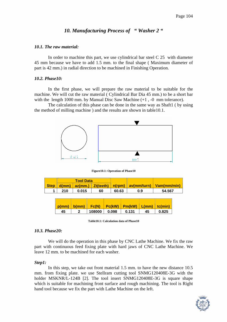
Page 104
10. Manufacturing Process of “ Washer 2 “
10.1. The raw material: In order to machine this part, we use cylindrical bar steel C 25 with diameter 45 mm because we have to add 1.5 mm. to the final shape ( Maximum diameter of part is 42 mm.) in radial direction to be machined in Finishing Operation. 10.2. Phase10: In the first phase, we will prepare the raw material to be suitable for the machine. We will cut the raw material ( Cylindrical Bar Dia 45 mm.) to be a short bar with the length 1000 mm. by Manual Disc Saw Machine (+1 , -0 mm tolerance). The calculation of this phase can be done in the same way as Shaft1 ( by using the method of milling machine ) and the results are shown in table10.1.
Figure10.1: Operation of Phase10
Tool Data
Step d(mm) az(mm.) Zt(teeth) n(rpm) av(mm/turn) Vam(mm/min) 1 210 0.015 60 60.63 0.9 54.567
p(mm) b(mm) Fc(N) Pc(kW) Pm(kW) L(mm) tc(min) 45 2 108000 0.098 0.131 45 0.825
Table10.1: Calculation data of Phase10
10.3. Phase20: We will do the operation in this phase by CNC Lathe Machine. We fix the raw part with continuous feed fixing plate with hard jaws of CNC Lathe Machine. We leave 12 mm. to be machined for each washer. Step1:
In this step, we take out front material 1.5 mm. to have the new distance 10.5 mm. from fixing plate. we use Stellram cutting tool SNMG120408E-3G with the holder MSKNR/L-124B [2]. The tool insert SNMG120408E-3G is square shape which is suitable for machining front surface and rough machining. The tool is Right hand tool because we fix the part with Lathe Machine on the left.

Page 105
Figure10.2: Operation of Phase20 Step1
Calculation of Step1: The calculation in this step is similar to the one of Shaft1 Phase20 Step1. The only difference is the average diameter of the machining position to calculate the rotation speed, in this case d = (45 + 0) / 2 = 22.5 mm. We can calculate by utilizing the equations 1,2,3,4,5,6 and 7. Step2: We will take out surface material 1.5 mm. in radious direction to have new diameter 42 h8 mm. in this step. We use Stellram tool insert DNMG150408E-3G and tool holder MDJNR/L-124B, both right and left hand.
Figure10.3: Operation of Phase20 Step2 Calculation of Step2: In order to calculate rotation speed (n), advance speed (a), cutting force (Fc), cutting power (Pc), machine power (Pm), cutting time (tc) and advance velocity (Va), all can be calculate by the equations 1,2,3,4,5,6 and 7. In this step, we use the average diameter to calculate the rotation speed as we have said in the calculation of phase20 step1 and we use Vc for finishing surface with carbide tool (see table1.2). The average diameter (d) in this case is (45 + 42)/2 = 43.5 mm. The cutting length (L) is 10.5 mm. Step3: In this step, we will drill a hole diameter 10 mm. and 10.5 mm depth. We use drill Garant 113260 diameter 10.5 mm. and cutting length 43 mm.

Page 106
Figure10.4: Operation of Phase20 Step3 Calculation of Step3: The calculation in this step can be done by using equations 6,7,8,9,10 and 11. The diameter of drill is 10 mm. , the cutting length is 10.5 mm. and the cutting velocity is 25 m/min. Step4: In this step, we will do the groove at the surface. The groove width 3.9 mm (+0.2, -0 mm. tolerance) deep 2.3 mm. and 2.05 mm. from the front surface. We use the cutting insert KCGP3156R (Kyocera) and the holder KKCR12-3C [3].
Figure10.5: Operation of Phase20 Step4 Calculation of Step4: In order to calculate rotation speed (n), cutting force (Fc), cutting power (Pc), machine power (Pm), cutting time (tc) and advance velocity (Va), all can be calculate by the equations 1,3,4,5,6 and 7 of Shaft1 and use Vc for finishing surface with carbide tool (see table1.3). Step5: This step is the final operation for each part. The objective is to cut the part to be small piece, width 8 mm. We use cutting insert tool KCGP3156R (Kyocera) and tool holder KKCR12-3C. After this process, we have to repeat Phase20 again in order to get more washers.

Page 107
Figure10.6: Operation of Phase20 Step5
Calculation of Step5: Although this step is the cutting process, we can use the same calculation process as in Phase20 Step1 of this part. We can calculate by utilizing the equations 1,2,3,4,5,6 and 7.
Step rp(mm) d(mm) n (rpm) p(mm) Ra(mm) a(mm/turn) S(mm2) Fc(N)1 0.031 22.5 2122 1.5 1.6 0.045 0.067 80.2 2 0.031 43.5 1317 1.5 1.6 0.045 0.067 80.2 3 10 636.6 0.1 600 4 0.2 39.7 1443 3.9 1.6 0.113 0.441 529 5 0.2 21 2274 2.175 1.6 0.113 0.246 295
Step Pc(kW) Pm (kW) L (mm) Va(mm/min) tc(min)
1 0.2 0.267 22.5 94.521 0.238 2 0.241 0.321 10.5 58.668 0.179 3 0.05 0.067 10.5 63.662 0.165 4 1.588 2.118 2.3 163.282 0.014 5 0.738 0.984 21 257.233 0.082
Table10.2: Calculation data of Phase20

Page 108
10.4. Calculation of Cycle Time for Washer 2:
Phase Step Task tm (s)
tch (s)
tph (s)
tpre (s)
thmp (s)
tun (s)
10 1 Cut the part 49.5 0.439 15 Cycle Time (s) 64.939
20 1 Tool moves into part 2 5.271 Frontal machining 14.28 Tool move out from the part 3 0.238 2 Tool moves into part 2 Finishing of external surface 10.74 Tool move out from the part 3 0.179 3 Tool moves into part 2 Drill a hole dia. 10 mm. 9.896 Tool move out from the part 3 0.247 4 Tool moves into part 2 Surface Groove width 3.9 mm 0.845 Tool move out from the part 3 0.014 5 Tool moves into part 2
Cutting of part to be small piece 4.898
Tool move out from the part 3 0.082 15 Total Time (s) 65.66 0.76 0 5.271 15 0 Cycle Time (s) 86.691
Total Time (s) 115.2 0.76 0 5.71 30 0 Total Cycle Time (s) 151.631
Table10.3: Cycle time for washer2

Page 109
11. Manufacturing Process of “ Gear 1 “
11.1. The raw material: The raw material for Gear1 is from forging process. The dimension is similar to the final shape. We decide to get raw material from forging because of better mechanical property and it’s faster than using raw part from steel bar. It’s possible to use casting process, but the part will have low flexion resistance which is the important mechanical property of the part. 11.2. Phase20: We start the operation of this part with CNC Lathe Machine. We fix the raw part at external diameter (96.5 mm.) by fixing plate with hard jaws. Step1:
We start machining the part by taking out front surface. In this operation, we employ Stellram cutting tool SNMG120408E-3G with the holder MSKNR/L-124B [2]. The tool insert SNMG120408E-3G is square shape which is suitable for machining front surface and rough machining. The tool is Right hand tool because we fix the part with Lathe Machine on the left.
Figure11.1: Operation of Phase20 Step1 Calculation of Step1: The calculation in this step is similar to the one of Shaft1 Phase20 Step1. The only difference is the average diameter of the machining position to calculate the rotation speed, in this case d = (96.5 + 53) / 2= 74.75 mm. We can calculate by utilizing the equations 1,2,3,4,5,6 and 7.

Page 110
Step2: In this step we will do the boring operation. We Bore to have a hole with diameter 62 mm. length 21 mm. and diameter 56 H7 mm. length 25.5 mm. We use cutting tool WBGW1.21_ (kyocera) with the tool holder S10H-SWUBR06-06 [3].
Figure11.2: Operation of Phase20 Step2 Calculation of Step2: The calculation in this step is similar to the one of Shaft1 Phase20 Step1. We can calculate by utilizing the equations 1,2,3,4,5,6 and 7 of Shaft1. The average diameter to calculate rotation speed is d = ( 62 + 56 ) / = 59 mm. The edge radius of tool is rp = 0.2 mm [3]. The total cutting length (L) is the summation of tool’s movement, L = 25.5 + ( 2 * 21 ) = 67.5 mm. Step3: In this step, we will make 3 chamfers, 2 mm. x 45 degree , 2 mm. x 30 degree and 3 mm. x 30 degree. We use Stellram tool insert DNMG150408E-3G and tool holder MDJNR/L-124B.
Figure11.3: Operation of Phase20 Step3

Page 111
Calculation of Step3: We can calculate by utilizing the equations 1,2,3,4,5,6 and 7 of Shaft1 in this process.
Step rp(mm) d(mm) n (rpm) p(mm) Ra(mm) a(mm/turn) S(mm2) Fc(N)1 0.031 74.75 638.7 1.5 1.6 0.045 0.067 120 2 0.2 59 971.1 3 1.6 0.113 0.339 611 3 0.031 71.5 801.3 1.5 1.6 0.045 0.067 120
Step Pc(kW) Pm (kW) L (mm) Va(mm/min) tc(min)
1 0.301 0.401 21.75 28.451 0.764 2 1.527 2.036 67.5 109.869 0.614 3 0.301 0.401 11.25 35.693 0.315
Table11.1: Calculation data of Phase20
11.3. Phase30: In this phase, we still use CNC Lathe Machine. We fix the raw part at internal dia 62 mm. with soft jaws and machine at the other side. Step1:
We will take out front surface in this operation. We employ Stellram cutting tool SNMG120408E-3G with the holder MSKNR/L-124B [2]. The tool insert SNMG120408E-3G is square shape which is suitable for machining front surface and rough machining. The tool is Right hand tool because we fix the part with Lathe Machine on the left.
Figure11.4: Operation of Phase30 Step1

Page 112
Calculation of Step1: The calculation in this step is similar to the one of Shaft1 Phase20 Step1. The only difference is the average diameter of the machining position to calculate the rotation speed, in this case d = (96.5 + 53) / 2= 74.75 mm. We can calculate by utilizing the equations 1,2,3,4,5,6 and 7. Step2: We will do Finishing of the external surface and make chamfer 2 x 45 degree and 2 x 30 degree in this step. We use Stellram tool insert DNMG150408E-3G and tool holder MDJNR/L-124B.
Figure11.5: Operation of Phase30 Step2 Calculation of Step2: We can calculate by utilizing the equations 1,2,3,4,5,6 and 7 of Shaft1 in this process.
Step rp(mm) d(mm) n (rpm) p(mm) Ra(mm) a(mm/turn) S(mm2) Fc(N)1 0.031 74.75 638.7 1.5 1.6 0.045 0.067 120 2 0.031 74.75 766.5 1.5 1.6 0.045 0.067 120
Step Pc(kW) Pm (kW) L (mm) Va(mm/min) tc(min)
1 0.301 0.401 21.75 28.451 0.764 2 0.361 0.481 50.14 34.141 1.469
Table11.2: Calculation data of Phase30

Page 113
11.4. Phase40: In this step, we will move to Broaching Machine in order to make the internal gear. We have to use Broaching Machine because the inner diameter is too small to be machined by other machine. We fix the part at diameter 93.5 mm. by fixing plate with soft jaws. Step1: This step is to make Internal Gear according to DIN 5480 60 x 2. This process will be done by Broaching Machine. The tool we use in this process is the tool for Gear shape 60x2 DIN 5480.
Figure11.6: Operation of Phase40 Step1
Calculation of Step1: The calculation of this operation can be done by using the equations 32, 33, 34, 35, 36, 37, 38, 39 and 40 of Transmission plate Phase50 Step1.
Step L(mm) p(mm) z(teeth) zt(teeth) nb tc(min) zw(teeth) 1 24 8.573 67 72 1 2.572 3
Step S(mm2) Fc(N) Pc(kW) Pm (kW)
1 1.84 9934 0.662 0.883
Table11.3: Calculation data of Phase40 11.5. Phase50: We will move to Gear Machine in this phase in order to make the external gear.

Page 114
Step1: We fix the part with Gear Machine and make the external gear according to the data in table10.4.
Table11.4: Data for external gear of Gear1
Calculation of Step1: We will start calculation with the tool rotaion speed. The gear cutting tool has the following data ; module (m) 3, diameter (d) 80 mm and tool’s teeth (ztool) 12 teeth. The rotation speed can be calculated by the following formula [6]. nf = ( Vc * 1000 ) / ( pi * d ) (41) np = nf / ztool (42) Where: Vc = Cutting speed (m/min) , in this case Vc = 30 m/min nf = Tool rotation speed (rpm) d = Diameter of tool (mm.) , in this case d = 80 mm. np = Part rotation speed (rpm) ztool = Number of tool’s teeth, in this case ztool = 12 Now we will calculate the cutting force (Fc) in order to get the machine power in the following step. It can be calculated by he following formula. Fc = σt * k * S (43) Where: k = constant depending on the type of material k = 3 for elastic material k = 5 for less or non elastic material (ex. Casting ) σt = Resistant of traction stress of material (N/mm2)

Page 115
S = The cutting surface = p * b p = Cutting depth of each pass = 3 in this case b = The average width of teeth = (1.75 + 3.5) / 2 = 2.625 in this case With the Cutting force obtained in the previous step, we are able to calculate the cutting power (Pc) and machine power (Pm) by the following formulas. Pc = ( Fc * Vam ) / 60000000 (44) Pm = Pc / η (45) Where: Pc = Cutting Power (kW) Pm = Machine Power (kW) Fc = Cutting Force (N) Vam = Tool advance speed (mm/min)
We also have to calculate the cutting time tc. In order to calculate it, we have to find the Cutting length (Lt) and Number of Cutting Pass (np). The calculation process can be done by the following formula [6]. tc = Lt / Vam (46) Lt = L + (r * cosα) (47) Where: tc = Cutting time (min) Lt = Total cutting length for 1 pass (mm.) Vam = Tool advance speed (mm/min) L = The thickness of gear (mm.) r = The outer radius of gear (mm.) α = 56.93 degree in this case m = Gear module p = Cutting depth of each pass = 3 in this case
Step m d(mm) nf (rpm) np (rpm) b(mm) p(mm) az(mm/min) S(mm2) Fc(N) 1 3 80 119.37 9.947 2.625 3 0.03 7.875 14175
Step Vam(mm/min) Pc(kW) Pm (kW) L (mm) l(mm) Lt(mm) tc(min)
1 42.972 0.01 0.014 45 21.83 66.83 1.555
Table11.5: Calculation data of Phase50 11.6. Phase60: We will do the Heat Treatment for this part by Carburizing Process all over the part withdepth 1 mm. (+0.1, -0.1 mm. tolerance) in order to reach the hardness 60-62 HRC. We will heat the part to 900 – 930 C in the carburizing oven which has more concentration of carbon than in the part. The time required for Carburizing

Page 116
Process is 720 min/lot ( 1 lot contains 20 parts). Then we have to do Quenching process which required 180 min/lot and finally Tempering process which required 30 min/lot. The total time required for this phase is 930 min/lot or 46.5 min/part ( This operation will be done by the external company). 11.7. Calculation of Cycle Time for Gear1:
Phase Step Task tm (s)
tch (s)
tph (s)
tpre (s)
thmp (s)
tun (s)
20 1 Tool moves into part 2 5.271 Frontal machining 45.87 Tool move out from the part 3 0.764 2 Tool moves into part 2 Boring operation 36.86 Tool move out from the part 3 0.614 3 Tool moves into part 2 Make chamfer 18.91 Tool move out from the part 3 0.315 15 Total Time (s) 116.6 1.694 0 5.271 15 0 Cycle Time (s) 138.606
30 1 Tool moves into part 2 120 Frontal machining 45.87 Tool move out from the part 3 0.764 2 Tool moves into part 2 Finish machining 88.11 Tool move out from the part 3 1.469 15 Total Time (s) 144 2.233 120 0 15 0 Cycle Time (s) 281.213
40 1 Tool moves into part 2 5.271 Make Internal Gear DIN 5480 52.98 Tool move out from the part 3 0.883 Total Time (s) 57.98 0.883 0 5.271 0 0 Cycle Time (s) 64.134
50 1 Tool moves into part 2 5.271 Make External Gear 93.3 Tool move out from the part 3 1.555 15 Total Time (s) 98.3 1.555 0 5.271 15 0 Cycle Time (s) 120.126
80 1 Carburizing and quenching 2790 Total Time (s) 416.9 6.365 120 15.813 45 2790 Total Cycle Time (s) 3394.079
Table11.6: Cycle time for Gear1

Page 117
12. Manufacturing Process of “ Gear 2 “
12.1. The raw material: The raw material for Gear2 is from forging process. The dimension is similar to the final shape. We decide to get raw material from forging because of better mechanical property and it’s faster than using raw part from steel bar. It’s possible to use casting process, but the part will have low flexion resistance which is the important mechanical property of the part. 12.2. Phase20: We start the operation of this part with CNC Lathe Machine. We fix the raw part at external diameter (81.5 mm.) by fixing plate with hard jaws. Step1:
We start machining the part by taking out front surface. In this operation, we employ Stellram cutting tool SNMG120408E-3G with the holder MSKNR/L-124B [2]. The tool insert SNMG120408E-3G is square shape which is suitable for machining front surface and rough machining. The tool is Right hand tool because we fix the part with Lathe Machine on the left.
Figure12.1: Operation of Phase20 Step1 Calculation of Step1: The calculation in this step is similar to the one of Shaft1 Phase20 Step1. The only difference is the average diameter of the machining position to calculate the rotation speed, in this case d = (81.5 + 35) / 2 = 58.25 mm. We can calculate by utilizing the equations 1,2,3,4,5,6 and 7.

Page 118
Step2: In this step we will do the boring operation. We Bore to have a hole with diameter 44 mm. length 23 mm. and diameter 38 H7 mm. length 23.5 mm. We use cutting tool WBGW1.21_ (kyocera) with the tool holder S10H-SWUBR06-06 [3].
Figure12.2: Operation of Phase20 Step2 Calculation of Step2: The calculation in this step is similar to the one of Shaft1 Phase20 Step1. We can calculate by utilizing the equations 1,2,3,4,5,6 and 7 of Shaft1. The average diameter to calculate rotation speed is d = (38 + 44) / 2 = 41 mm. The edge radius of tool is rp = 0.2 mm [3]. The total cutting length (L) is the summation of tool’s movement, L = 23.5 + ( 2 * 23 )= 69.5 mm. Step3: In this step, we will make 3 chamfers, 2 mm. x 45 degree , 2 mm. x 30 degree and 3 mm. x 30 degree. We use Stellram tool insert DNMG150408E-3G and tool holder MDJNR/L-124B.
Figure12.3: Operation of Phase20 Step3

Page 119
Calculation of Step3: We can calculate by utilizing the equations 1,2,3,4,5,6 and 7 of Shaft1 in this process.
Step rp(mm) d(mm) n (rpm) p(mm) Ra(mm) a(mm/turn) S(mm2) Fc(N)1 0.031 58.25 819.7 1.5 1.6 0.045 0.067 120 2 0.2 41 1397 3 1.6 0.113 0.339 611 3 0.031 54.5 1051 1.5 1.6 0.045 0.067 120
Step Pc(kW) Pm (kW) L (mm) Va(mm/min) tc(min)
1 0.301 0.401 23.25 36.51 0.637 2 1.527 2.036 69.5 158.104 0.44 3 0.301 0.401 11.25 46.827 0.24
Table12.1: Calculation data of Phase20
12.3. Phase30: In this phase, we still use CNC Lathe Machine. We fix the raw part at internal dia 62 mm. with soft jaws and machine at the other side. Step1:
We will take out front surface in this operation. We employ Stellram cutting tool SNMG120408E-3G with the holder MSKNR/L-124B [2]. The tool insert SNMG120408E-3G is square shape which is suitable for machining front surface and rough machining. The tool is Right hand tool because we fix the part with Lathe Machine on the left.
Figure12.4: Operation of Phase30 Step1

Page 120
Calculation of Step1: The calculation in this step is similar to the one of Shaft1 Phase20 Step1. The only difference is the average diameter of the machining position to calculate the rotation speed, in this case d = (81.5 + 35) / 2 = 58.25 mm. We can calculate by utilizing the equations 1,2,3,4,5,6 and 7. Step2: We will do Finishing of the external surface and make chamfer 2 x 45 degree and 2 x 30 degree in this step. We use Stellram tool insert DNMG150408E-3G and tool holder MDJNR/L-124B.
Figure12.5: Operation of Phase30 Step2 Calculation of Step2: We can calculate by utilizing the equations 1,2,3,4,5,6 and 7 of Shaft1 in this process.
Step rp(mm) d(mm) n (rpm) p(mm) Ra(mm) a(mm/turn) S(mm2) Fc(N)1 0.031 58.25 819.7 1.5 1.6 0.045 0.067 120 2 0.031 59.75 958.9 1.5 1.6 0.045 0.067 120
Step Pc(kW) Pm (kW) L (mm) Va(mm/min) tc(min)
1 0.301 0.401 21.75 36.51 0.596 2 0.361 0.481 50.14 42.713 1.174
Table12.2: Calculation data of Phase30

Page 121
12.4. Phase40: In this step, we will move to Broaching Machine in order to make the internal gear. We have to use Broaching Machine because the inner diameter is too small to be machined by other machine. We fix the part at diameter 78.5 mm. by fixing plate with soft jaws. Step1: This step is to make Internal Gear according to DIN 5480 42 x 2. This process will be done by Broaching Machine. The tool we use in this process is the tool for Gear shape 42x2 DIN 5480.
Figure12.6: Operation of Phase40 Step1
Calculation of Step1: The calculation of this operation can be done by using the equations 32, 33, 34, 35, 36, 37, 38, 39 and 40 of Transmission plate Phase50 Step1.
Step L(mm) p(mm) z(teeth) zt(teeth) nb tc(min) zw(teeth) 1 22 8.208 67 72 1 2.463 3
Step S(mm2) Fc(N) Pc(kW) Pm (kW)
1 1.56 8424 0.562 0.749
Table12.3: Calculation data of Phase40 12.5. Phase50: We will move to Hobbing Machine in this phase in order to make the external gear.

Page 122
Step1: We fix the part with Hobbing Machine and make the external gear according to the data in table11.4.
Table12.4: Data for external gear of Gear1
Calculation of Step1: Every calculation can be done in the same way as Gear1 Phase50. We can use equations 41, 42, 43, 44, 45, 46 and 47 to calculate.
Step m d(mm) nf (rpm) np (rpm) b(mm) p(mm) az(mm/min) S(mm2) Fc(N) 1 3 80 119.366 9.947 4.64 3 0.03 13.92 25056
Step Vam(mm/min) Pc(kW) Pm (kW) L (mm) l(mm) Lt(mm) tc(min)
1 42.972 0.018 0.024 45 21.83 66.83 1.555
Table12.5: Calculation data of Phase50 12.6. Phase60: We will do the Heat Treatment for this part by Carburizing Process all over the part withdepth 1 mm. (+0.1, -0.1 mm. tolerance) in order to reach the hardness 60-62 HRC. We will heat the part to 900 – 930 C in the carburizing oven which has more concentration of carbon than in the part. The time required for Carburizing Process is 720 min/lot ( 1 lot contains 20 parts). Then we have to do Quenching

Page 123
process which required 180 min/lot and finally Tempering process which required 30 min/lot. The total time required for this phase is 930 min/lot or 46.5 min/part ( This operation will be done by the external company). 12.7. Calculation of Cycle Time for Gear2:
Phase Step Task tm (s)
tch (s)
tph (s)
tpre (s)
thmp (s)
tun (s)
20 1 Tool moves into part 2 5.271 Frontal machining 38.21 Tool move out from the part 3 0.637 2 Tool moves into part 2 Boring operation 26.37 Tool move out from the part 3 0.44 3 Tool moves into part 2 Make chamfer 14.41 Tool move out from the part 3 0.24 15 Total Time (s) 94 1.317 0 5.271 15 0 Cycle Time (s) 115.586
30 1 Tool moves into part 2 120 Frontal machining 35.74 Tool move out from the part 3 0.596 2 Tool moves into part 2 Finish machining 70.43 Tool move out from the part 3 1.174 15 Total Time (s) 116.2 1.77 120 0 15 0 Cycle Time (s) 252.944
40 1 Tool moves into part 2 5.271 Make Internal Gear DIN 5480 44.93 Tool move out from the part 3 0.749 Total Time (s) 49.93 0.749 0 5.271 0 0 Cycle Time (s) 55.948
50 1 Tool moves into part 2 5.271 Make External Gear 93.3 Tool move out from the part 3 1.555 15 Total Time (s) 98.3 1.555 0 5.271 15 0 Cycle Time (s) 120.126
80 1 Carburizing and quenching 2790 Total Time (s) 358.4 5.39 120 15.813 45 2790 Total Cycle Time (s) 3334.603
Table12.6: Cycle time for Gear2

Page 124
13. Choosing the proper machine
13.1. CNC Lathe Machine In order to choose the specific machine for turning operation, we have to consider the data of every operation employed by CNC Lathe Machine. The data including maximum machine power (Pm) and maximum rotation speed (n) for each operation, the data are shown in table12.1.
Part Max. Rotation Speed (rpm) Max. Power (kW) Shaft 1 2329.097 9 Shaft 2 1671.162 9 Gear 1 971.115 2.036 Gear 2 1397.458 2.036
Pin 3000 0.535 Transmission Plate 1591.549 1.629
Washer 2273.642 2.118
Table13.1: The Maximum machine power and rotation speed of turning operation As we see in table12.1, the maximum machine power is 9 kW and the maximum rotation speed is 3000 rpm, so we have to choose the machine which can support these requirements. According to the data above, we decide to choose CNC Lathe Machine from “ Haas Automation “ Model: SL-10HE , the machine details are shown below [8].
Figure13.1: CNC Lathe Machine Model: SL-10HE

Page 125
Supplier: Haas Automation
Model: SL-10HE Price: 39,900 euros Details: CNC Lathe; 11" (279mm) x 14" (356mm) (maximum), 16.25" (413mm) swing, 15-hp (11.2kw), 100-6000 rpm, A2-5 spindle, 6.5" (165mm) chuck,12-station VDI30 turret,1MB, internal transformer, export packing, floppy drive, chip auger, macros, Visual Quick Code, rigid tapping, spindle orientation, tool presetter. 13.2. CNC Milling Machine With the same method, in order to choose the specific machine for milling operation, we have to consider the data of every operation employed by CNC Milling Machine. The data including maximum machine power (Pm) and maximum rotation speed (n) for each operation, the data are shown in table12.2.
Part Max. Rotation Speed
(rpm) Max. Power
(kW) Shaft 1 1273.24 0.196 Shaft 2 5500 0.131 Casing 4774.648 0.321
Sliding Part 5092.958 0.171 Clutch Fork 4774.648 0.233
Pin 1273 0.054 Sealing plate1,2 4774.648 0.321
Transmission Plate 795.775 0.091
Table13.2: The Maximum machine power and rotation speed of milling operation
As we see in table12.2, the maximum machine power is 0.321 kW and the maximum rotation speed is 5500 rpm, so we have to choose the machine which can support these requirements. According to the data above, we decide to choose CNC Milling Machine from “ CNC Masters “ Model: CNC Supra Vertical Knee-Type Milling Machine , the machine details are shown below [9].

Page 126
Figure13.2: CNC Milling Machine Model: CNC Supra Vertical Knee-Type Supplier: CNC Masters
Model: CNC Supra Vertical Knee-Type Price: 6,971 euros General data:
- Super Strong Column and Base - High Precision Class 7 Spindle Bearings - X, Y, Z Zero-Backlash Ball Screws with Pre-Loaded Ball Nuts - X, Y, Size 34 Micro-Stepping Motors at 1500 in/oz of torque with Hand Wheels - Z, Size 34 Micro-Stepping Motor at 1200 in/oz of torque with Hand Wheel - 9" x 49" table - variable spindle speed computer controlled - Ground table t-slots - Hardened & ground ways - Hardened & ground table - Built-In Coolant Column Base (Computer Control Pump, Hose, and Flex Nozzle
mounted next to quill--optional accessory) - Built-In One-Shot Auto Lube
Tolerances:
- Accuracy is +/- 0.003" in 12" (+/- 0.00025 per inch) - Repeatability is within 0.0005" - Resolution is 0.0002" of linear motion on the X, Y, and Z.
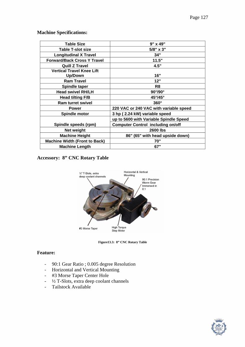
Page 127
Machine Specifications:
Table Size 9" x 49" Table T-slot size 5/8" x 3"
Longitudinal X Travel 34" Forward/Back Cross Y Travel 11.5"
Quill Z Travel 4.5" Vertical Travel Knee Lift
Up/Down 16" Ram Travel 12"
Spindle taper R8 Head swivel RH/LH 90°/90°
Head tilting F/B 45°/45° Ram turret swivel 360°
Power 220 VAC or 240 VAC with variable speed Spindle motor 3 hp ( 2.24 kW) variable speed
up to 5600 with Variable Spindle Speed Spindle speeds (rpm) Computer Control including on/off
Net weight 2600 lbs Machine Height 86" (65" with head upside down)
Machine Width (Front to Back) 70" Machine Length 67"
Accessory: 8” CNC Rotary Table
Figure13.3: 8” CNC Rotary Table Feature:
- 90:1 Gear Ratio ; 0.005 degree Resolution - Horizontal and Vertical Mounting - #3 Morse Taper Center Hole - ½ T-Slots, extra deep coolant channels - Tailstock Available

Page 128
13.3. Manual Grinding Machine
In order to choose the specific machine for grinding operation, we have to consider the data of every operation employed by Manual Grinding Machine which are only two operations of Shaft1 and Shaft2. The data including maximum machine power (Pm) and maximum rotation speed (n) for each operation, the data are shown in table12.3.
Part Max. Rotation Speed
(rpm) Max. Power
(kW) Shaft 1 1800 0.54 Shaft 2 1800 0.54
Table13.3: The Maximum machine power and rotation speed of grinding operation
As we see in table12.3, the maximum machine power is 0.54 kW and the maximum rotation speed is 1800 rpm, so we have to choose the machine which can support these requirements. According to the data above, we decide to choose Manual Grinding Machine from “ Precision Machine Tool. “ Model: PMT/300/125, the machine details are shown below [10].
Figure13.4: Manual Grinding Machine Model: PMT/300/125

Page 129
Supplier: Precision Machine Tool. Model: PMT/300/125 Price: 596.7 euros Specification: 13.4. Broaching Machine With the same method, in order to choose the specific machine for broaching operation, we have to consider the data of every operation employed by Broaching Machine. The data including with maximum machine power (Pm) for each operation, the data are shown in table12.4.
Part Max. Power (kW) Gear 1 0.883 Gear 2 0.749
Transmission Plate 0.461
Table13.4: The Maximum machine power of broaching operation
As we see in table12.4, the maximum machine power is 0.883 kW, so we have to choose the machine which can support this requirement. According to the data above, we decide to choose Broaching Machine from “APM Pavia Co., Ltd. “ Model: SLOTTING CNC-200S, the machine details are shown below [11].

Page 130
Figure13.5: Broaching Machine Model: Slotting CNC-200S Supplier: APM Pavia Co., Ltd. Model: SLOTTING CNC-200S Price: 6,500 euros General data:
- Gear driven - Brake motor - Automatic feed and index - Forced lubrication system - Ram can swivel 10" forward
Specifications:
- Max. stroke: 200mm. - Indexing ratio: 1:90. - Dividing number: 0 ~ 999. - Ram speed (spm): 27, 42, 67, 105. - Longitudinal travel: 510mm. - Transversal travel: 440mm. - Main drive motor: 3HP (2.238 kW).
13.5. Hobbing Machine In order to choose the specific machine for gear machining operation, we have to consider the data of every operation employed by Hobbing Machine. The data including maximum machine power (Pm) and maximum rotation speed (n) for each operation, the data are shown in table12.5.
Part Max. Rotation Speed
(rpm) Max. Power
(kW) Gear 1 119.4 0.014 Gear 2 119.4 0.024
Table13.5: The Maximum machine power of gear machining operation

Page 131
As we see in table12.5, the maximum machine power is 0.024 kW and the maximum rotation speed is 119.4 rpm, so we have to choose the machine which can support these requirements.
According to the data above, we decide to choose Hobbing Machine from
“ LIEBHERR “ Model: LC-120, the machine details are shown below [12].
Figure13.6: Hobbing Machine Model: LC-200 Supplier: LIEBHERR Model: LC-120 Price: 35,000 euros Details: - Maximum Module [mm] 3 - Workpiece diameter [mm] 125 - Axial travel [mm] 250 (400) - Shift travel [mm] 180 - Hob diameter [mm] 90 - Hob length [mm] 210 - Hob speed [1/min] 5500

Page 132
13.6. Manual Disc Saw Machine In order to choose the specific machine for saw operation, we have to consider the data of every operation employed by Saw Machine. The data including maximum machine power (Pm) and maximum rotation speed (n) for each operation, the data are shown in table12.6.
Part Max. Rotation Speed
(rpm) Max. Power
(kW) Shaft 1 60.63 0.319 Shaft 2 60.63 0.253
Sliding Part 60.63 0.099 Pin 60.63 0.052
Washer 60.63 0.131
Table13.6: The Maximum machine power of saw operation
As we see in table12.6, the maximum machine power is 0.3187 kW and the maximum rotation speed is 60.63 rpm, so we have to choose the machine which can support these requirements
According to the data above, we decide to choose Broaching Machine from “Hangzhou Yangyang Machinery-Equipment Tools & Hardware Co., Ltd. “ Model: YY-131-004, the machine details are shown below [13]. Figure13.7: Manual Disc Saw Machine Model: YY-131-004 Supplier: Hangzhou Yangyang Machinery-Equipment Tools & Hardware Co., Ltd. Model: YY-131-004 Price: 800 euros Details:
- Blade diameter: 210mm - Rated voltage: 120V/240V

Page 133
- Rated input power: 1,300W - No load speed: 4,500r/min
- Net weight: 12.5kg 13.7. Manual Sensitive Press
We decide to choose Sensitive Machine from “ Eitel Presses Inc. “ Model:10T, the machine details are shown below [14].
Figure13.8: Manual Sensitive Press Machine Model: 10 T Supplier: Eitel Presses Inc. Model: 10 T Price: 1,200 euros Details:
- Design: C-frame with hand-load, hand operated traveling carriage for unlimited straightening points. It can straighten parts up to 20 feet in length depending on part diameter.
- Control: Manual through the use of a hand lever connected to the control valve via mechanical linkages.
- Straightening Process: The operator hand loads the part into the straightening station and clamps the part in centers (or on rollers). The part is then rotated manually to measure the TIR using dial indicators and the high point is rotated up. The operator will then depress the hand lever, which brings the ram down to the part causing the part to flex. The depth of the stroke is adjusted using the fine stroke adjustment on the hand lever. After each stroke, the dial indicator will show how much the TIR of the part has changed so that the operator can increase the depth of stroke until the TIR is within customer specifications. This process is repeated at operator determined points along the work piece as necessary to achieve the specified straightness.

Page 134
14. Calculation of the Machines Amount Required
In order to know the number of the machine (Nm) required for this project, we have to analyze the data obtained in the previous chapter. We have to take into account the total cycle time of each machine and the expected production amount per year (from marketing study). We concept of this calculation is that we divide time required to machine parts per year by the operation time we have per year. The time required to machine parts per year is the multiplication of expected production amount per year (Pexpect) and the total cycle time of each machine (Ctot), its unit is h/year. The operation time we have per year is determined from the assumptions that we have 220 working days/year, 1 shift/day and 7.75 h/shift. The formula to proceed this calculation is shown below. Nmc = ( Pexpect * (Ctot / 3600) ) / ( 7.75 * 220 * 1 ) (48) Where: Nmc = The calculation number of the machine Pexpect = The expected production amount per year = 7513 parts/year Ctot = The total cycle time of each machine (s) We also have to calculate the % of Work Load of the machine in order to manage each operation. If the % of Work Load is too low ( less than 40 % ), we may have to think about using the external sub-contract company instead of investing the new machine. If the % of Work Load is more than 90 %, we should add 1 more machine to avoid the over capacity situation. The % of Work Load can be found by the following equation. % of Work Load = ( Nmc / Nmr ) * 100 (50) Where: Nmc = The calculation amount of the machine Nmr = The real amount of machine
The results of The number of the machine (Nm) by using equation 48 and 49 are shown in table14.1.
Machine Total Cycle Time (s) Nm (calculation) Nm (real) % of Work Load CNC Lathe 2952.634 3.614 5 72.281 CNC Milling 3651.178 4.469 5 89.382
Grinding 595.988 0.729 1 72.95 Broaching 173.462 0.212 1 21.232 Hobbing 240.252 0.294 1 29.407
Sensitive Press 180 0.22 1 22.032 Disc Saw 336.649 0.412 1 41.206
Oven 11160 4.553 6 75.889
Table14.1: The amount of Machines

Page 135
According to the data in table13.1, there are 3 machines that have % of work load lower than 40 %. We could think about using the external sub-contract company to do these operations. However, in our case we also have to consider the increasing of production in the following year. With this reason, we can conclude that it would be worth enough to invest Broaching, Hobbing and sensitive Press Machine since the 1st year. However, in the case of Heat Treatment Process, it will be better to use the external sub-contract company to do, because this is the process which spends lots of time and it will increase the cost of product as well. Another reason is that heat treatment is usually the last process of the operation, this make it be easier to manage the process by the external company.
15. Calculation of the Workers Amount Required
We can calculate the amount of the Operator by analyzing the operation time done by human for each part. The operation time to be done by operator including; Phase changing time (tph) , Machine preparation time (tpre) , Time for taking out the finished part (thmp) , Time for verification (thmm) , Time for un-machine phase (tun) and some of Machining time from manual process (tm). It’s clear that Phase changing time (tph) , Machine preparation time (tpre) , and Time for taking out the finished part (thmp) and Time for verification (thmm) have to be done by the operator, but not every Time for un-machine phase (tun) is done by operator. The process that we take tun into account for example to paint the anti-carburizing to the part. We also take into account the Machining time (tm) for Manual Machine. The concept to calculate the amount of workers (Nwc) is similar to the one of the machine amount calculation. The formula is shown below. Nwc = [ ( thuman / 3600 ) * Pexpect] / ( 7.75 * 220 * 1 ) (51) Where: Nwc = The calculation amount of the workers thuman = The summation of operation time done by human for every part(s) = Sum( tph + tpre + thmp + thmm + tun + tm ) Pexpect = The expected production amount per year = 7513 parts/year

Page 136
Machine tph (s) tpre (s) thmp (s) thmm (s) tun (s) tm (s) Nwc Nwr Shaft1 360 11.420 105 30 150 474.9 Shaft2 360 11.420 135 30 210 594.2 Casing 240 5.271 45 30 0 0
Deslizamiento 240 5.71 45 30 0 68.16 Gear1 120 15.813 45 30 0 58.863 Gear2 120 15.813 45 30 0 50.679 5.889 6
Clutch Fork 240 5.271 30 30 0 0 Pin 120 10.981 60 30 0 13.19
Tapa Sellado1,2 120 5.271 30 30 0 0 Transmission Plate2 120 15.813 60 30 0 33.111
Washer2 0 5.7101 30 30 0 49.5 Total 2040 108.492 630 330 360 1342.6
Table15.1: The amount of workers ( Operator of Machine )
The amount of operator (Nwr) obtained in table15.1 are the workers who work with the machine only. In fact, we have to add 2 more workers for the assembly job. We also have to consider about the other positions such as Maintenance technician, Engineer, Manager and Officer ( including accounting, human resource, secretary etc.). The estimation of the amount and the salary rate are shown in table 15.2.
Position Amount Salary Rate (euros/year) Total Salary (euros/year) Operator of Machine 6 16000 96000 Worker for Assembly 2 14000 28000
Maintenance Technician 2 17000 34000 Officer 2 16000 32000
Engineer 1 21000 21000 Manager 1 40000 40000
Total 14 251000
Table15.2: The amount of workers and salary rate for all positions

Page 137
16. Economic Study
16.1. Hour Cost
Hour Cost is the important factor to calculate the product cost. It is the total cost of the company in one hour. It means that in every hour passed, company has to pay the money equal to Hour Cost. The Hour Cost is included with four factors, Amortization (A), Power (B), Salary (C), General (D). The formula to calculate Hour Cost is shown below. Hour Cost = ( A + B + C + D ) / Total Direct Working Hour (52) Where: A = Amortization Cost (euros/year) B = Electric Power Cost (euros/year) C = Total Salary of employees (euros/year) D = General Cost, for ex. water, telephone, etc. Amortization Cost (A): Amortization Cost is the investment cost of company divide by the expected utilization year. For example, the machines are expected to be used for 5 years, after the 5th year it may be not in the good condition to produce a quality product, so the investment cost of the machines have to be divided by 5 in order to get the Amortization Cost for machines. The Amortization Cost we consider are 1.The Construction of Production Plant , 2.Construction of Office and 3.The Machines (see table16.2 for details of machine investment cost). The formula to calculate Amortization Cost is shown below. A = Sum(Pi/Ni) (53) Where: Pi = Investment Cost (euros) Ni = The number of expected utilization year of each investment (year) The result of Amortization Cost are shown in the table below.
Type of Investment Total Cost
(euros) Number of year Amortization (euros/year)
Construction of Production Plant 1500000 10 150000 Machines 278451.7 5 55690.34
Total Amortization 205690.34
Table16.1: The Amortization Cost

Page 138
Machine Amount
(unit) Price
(euros/units) Total Cost
(euros) Lathe Machine 5 39900 199500 Milling Machine 5 6971 34855
Grinding Machine 1 596.7 596.7 Broaching Machine 1 6500 6500 Hobbing Machine 1 35000 35000 Sensitive Press 1 1200 1200
Disc Saw 1 800 800 Total Machine Cost 278451.7
Table16.2: Show the details of investment cost of each machines and its amount
Electric Power Cost (B): Electric Power Cost is the cost of electric consumption of the company. The details of Electric Power Cost are shown in table16.3.
We estimate the electric consumption of the machines by using the average Machine Power (Pm) obtained in the calculation part multiply by the number of the machines. This estimation is based on the assumption that every machine are running during the working hour. The formula to calculate the Electric Power Cost (B) is shown below. The constant for this formula are shown in table16.4. B = Total Power * f * P * Nhf (54) Where: Total Power = The summation of every consumption in the company (kW) f = Factor of utilization = 0.5 – 0.8 P = Electricity price rate (euros/kWhr), we use 0.083728 euros/kWhr [17] Nhf = Working hours per year (hr) = 220 * 7.75 * 1 = 1705 hr/year
Type of Consumption Avg. Power per 1
unit (kW) Amount
(unit) Total Power
(kW) Power Cost, B (euros/year)
Lathe Machine 3.765 5 18.825 1881.17 Milling Machine 0.19 5 0.9485 94.783
Grinding Machine 0.54 1 0.54 53.962 Broaching Machine 0.698 1 0.698 69.751 Hobbing Machine 0.019 1 0.019 1.899
Disc Saw 0.171 1 0.171 17.064 Computer 0.36 6 2.16 215.847
Air Conditioner 2 3 6 599.576 Heater 2 3 6 599.576
Other office equipment 4 399.717 Total Electric Power Cost per Year 3933.346
Table16.3: Total Electric Power Cost per Year

Page 139
Constant Value Unit Electricity price rate ( P ) 0.084 euros/kWhr
Working hour per year ( Nhf) 1705 hr/year factor 0.7
Table16.4: The Constants to be used in equation54
Salary Cost (C): We define the salary for each positions by considering the difficulties of the job functions and the skill required for each position. The details of this task are shown in table16.5.
Position Amount Salary Rate (euros/year) Total Salary (euros/year) Operator of Machine 6 16000 96000 Worker for Assembly 2 14000 28000
Maintenance Technician 2 17000 34000 Officer 2 16000 32000
Engineer 1 21000 21000 Manager 1 40000 40000
Total 14 251000
Table16.5: Total Salary Cost per year General Cost (D): The General Cost is the estimation of the other possible cost for the company, for example Water, Telephone etc. The details are shown in table16.6.
Type of General Cost Cost (euros/year) Water 1700
Telephone 1700 Office Materials 1700
Soap & Oil 2000 Transport 4000
Taxes 50000 Maintenance 8000
Total 69100
Table16.6: Total General Cost

Page 140
The Total Direct Working Hour is the total working time of the workers who work directly with the product or we can say that it’s the working time of the workers who produce the product, including with the Operator of Machines and the Workers for Assembly line. In our case, we have 8 direct workers who work approximately 220 days/year and 7.75 hours/day ( we just consider 1 shift/day), so the Total Direct Working Hour is 220 * 7.75 * 8 = 13640 hours/year.
Finally, we add the cost A, B, C and D from table16.1, 16.3, 16.5 and 16.6
together, then divide by Total Working Hour according to equation 52, Hour Cost will be obtained (see table16.7).
Cost Unit Amortization ( A ) 205690.34 euros/year
Power ( B ) 3933.346 euros/year Salary ( C ) 251000 euros/year
General ( D ) 69100 euros/year Total Cost 529723.69 euros/year Hour Cost 38.836 euros/hour
Table16.7: Hour Cost
16.2. The Price of the cost of the Product ( Pc ) In order to calculate the price of the cost of the product (Pc), we have to use Hour Cost obtained in 16.1, the production time to machine 1 part ( tprod, total cycle time ) and the cost of raw material. Because we decide to do Heat Treatment from the external company, so the tprod will not include the cycle time for the heat treatment process for each part. The price of the product are shown in table16.8. and the formula to calculate the price of the product is shown below. Pc = ( Hour Cost * tprod ) + Pmat + Ptool (56) Where: tprod = total production time to machine 1 part exclude Heat Treatment Process which has to be done by external company (hr) Pmat = The cost of raw material for each part and include the hiring cost of heat treatment with the external company Ptool = The estimation cost of tool = 10 euros/part The cost of raw materials (Pmat) are different for each part depending on the preprocess of the raw parts. Some parts for example shaft1, we can use the round bar and buy it directly from the steel manufacturer. But for some parts for example casing, we have to hire the external company to do this casting part (it’s shown in Sub Contract Cost). We do the estimation of the price for casting and forging process, which are: Casing from casting process 22 euros/part, Tapasellado from casting process 7 euros/part, Gear1 and 2 from forging process 13 euros/part, Clutch Fork from forging process 2 euros/part, Transmission Plate from forging process 12 euros/part.

Page 141
In the calculation of Pmat, we take into account the cost for doing heat treatment by external company (it’s shown in Sub Contract Cost). The prices are different between carburizing and normal heat treatment. We estimate the price for carburizing is 21 euros/part and 7 euros/part for normal heat treatment. The price of some shape of steel is shown in table16.8 and the cost of raw materials (Pmat) are shown in table16.9.
Type of Steel Cost Unit Round Bar Dia. 73 mm. 53.661 euros/m Round Bar Dia. 58 mm. 31.297 euros/m
Plate 20x1800 mm. 194.483 euros/m2
Round Bar Dia. 12 mm. 1.2646 euros/m Round Bar Dia. 45 mm. 17.483 euros/m
Table16.8: Steel Price [18]
Part Raw Material Material Used m, m2 per part
Price (euros/part)
Sub Contract Cost
(euros/part) Total Price (euros/part)
Shaft1 Round Bar Dia. 73
mm. 0.176 9.431 21 19.431
Shaft2 Round Bar Dia. 58
mm. 0.141 4.397 21 14.397 Casing From Casting Process 22 10
Deslizamiento Plate 20x1800 mm. 0.001 0.145 0.145
Gear1 From Forging
Process 34 16
Gear2 From Forging
Process 34 15
Clutch Fork From Forging
Process 9 11
Pin Round Bar Dia. 12
mm. 0.088 0.111 7 5.111 Sealing plate1,2 From Casting Process 7 6 Transmission
Plate2 From Forging
Process 19 13
Washer2 Round Bar Dia. 45
mm. 0.013 0.219 0.219
Table16.9: Raw Material Cost for each part

Page 142
Part tprod (hr) Pmat
(euros) Ptool
(euros) Price of Cost of the Product, Pc
(euros) Shaft1 0.492 30.431 Shaft2 0.52 25.397 Casing 0.301 22
Deslizamiento 0.143 0.145 Gear1 0.168 34 Gear2 0.151 34
Clutch Fork 0.096 9 Pin 0.071 7.111
Tapa Sellado1,2 0.28 7 Transmission Plate2 0.145 19
Washer2 0.049 0.219 Total 2.417 188.303 10 292.173
Table16.10: The Price of the Cost of the Product
16.3. Inversion Cost ( Cinv ) In general, when the company start manufacturing the product, it usually suffer the Inversion Cost during the first 3 months. Inversion Cost is the cost that the company has to pay without obtaining any profit, because of some circumstance for example machine test run. In order to calculate the Inversion Cost, we have to take into account all of the cost in the first 3 months. The details of Inversion Cost are shown in Table16.11.
Calculation of Inversion Cost Type of Cost Cost (euros)
Investment of Machines 278451.7 Construction of Production Plant 1500000
General Cost ( 3 months ) 17275 Salary ( 3 months ) 62750
Electricity Cost ( 3 months ) 983.336 Study of the Project 6000
Unexpected Cost 8000 Inversion Cost (Cinv) 1873460.036
Table16.11: Inversion Cost for the first 3 months
16.4. Selling Price of the Product (Pv) In order to define the selling price of the product (Pv), we have to consider the Price of Cost of the Product (Pc), the Inversion Cost (Cinv) and the expected production amount. In the calculation, we use the Bank Interest (i) 4 % and the expect profit 10 % of the Pc. The formula is shown below and the details of the calculation are shown in table16.12.

Page 143
Pv = Pc + [{Cinv*(i/100)}/(product per year)] + [Pc*(expected profit/100)] (57) Where: Pv = Selling Price of the Product (euros) Pc = Price of Cost of the Product (euros) Cinv = The Inversion Cost (euros) product per year = 7513 part/year i = Bank Interest = 4 % expected profit = 10 %
Selling Price of Product ( Pv ) Price of Cost of the Product ( Pc ) 292.173 euros/part
Inversion Cost (Cinv) 1873460.036 euros Bank Interest ( i ) 4 %
Number of Expected Production per Year 7513 part/year Expected Profit ( % of Pc ) 10 %
Selling Price of Product ( Pv ) 331.364 euros/part
Table16.12: The Selling Price of the Product 16.5. The Situation of the Company in the Next 5 years In this task, we shall do the estimation of the situation of the company in the next 5 years according to the marketing study. The estimation data in this step will be useful and necessary to calculate cash flow and the pay back period in the following steps. The estimation data are shown in table16.13.
Company's Situation in the next 5 years 2008 2009 2010 2011 2012 Expected Production per Year 7513 10137 12760 15383 18006
Direct Workers 8 10 12 14 16 Lathe Machine 5 6 7 8 9 Milling Machine 5 6 7 8 9
Grinding Machine 1 2 2 3 3 Broaching Machine 1 1 1 1 1 Hobbing Machine 1 1 1 1 1 Sensitive Press 1 1 1 1 1
Disc Saw 1 2 2 3 3
Table16.13: The Situation of the Company in the Next 5 years * Direct Worker are the operator of machine and the worker for assembly

Page 144
16.6. Cash Flow Cash Flow is the important factor to know if the business is profitable. The concept to calculate is that we make the summation of the income and expense of the company in each year. The data to calculate cash flow are shown in table16.14, the sign – is for the expense and the sign + is for the income. In order to calculate the Tax ( 35 % of the Profit before Tax subtracted ), we have to deduct the Amortization Cost of Plant Construction and Investment of Machine. To know the Cash Flow, we shall add the Amortization Cost of Plant Construction and Investment of Machine to the Profit after Tax subtracted again. The details of the calculation are shown in table16.14.
Cash Flow 2008 2009 2010 2011 2012 Sale Volume 2489540.4 3359040.5 4228209.2 5097378 5966546.7
Cutting Tool and Material's Cost -1489852.7 -2010200.6 -2530350 -3050500 -3570649 Salary -251000 -283000 -315000 -347000 -379000
Electricity Cost -3933.346 -4399.562 -4794.753 -5260.969 -5656.16 General Cost -69100 -69100 -69100 -69100 -69100
675654.4 992340.4 1308964.4 1625517 1942141.3Amortization of Machines -55690.34 -55690.34 -55690.34 -55690.34 -55690.34
Amortization of Plant Construction -150000 -150000 -150000 -150000 -150000 Profit before Tax subtracted 469964.06 786650.06 1103274 1419827 1736450.9
Tax subtracted ( 35% ) -164487.42 -275327.52 -386145.9 -496939.4 -607757.8 Profit after Tax subtracted 305476.64 511322.54 717128.12 922887.5 1128693.1Amortization of Machines 55690.34 55690.34 55690.34 55690.34 55690.34
Amortization of Plant Construction 150000 150000 150000 150000 150000 Cash Flow Net 511166.98 717012.88 922818.46 1128578 1334383.5
Table16.14: Cash Flow
* We assume that the cutting tool’s cost is 10 euros/part. 16.7. Period of Pay Back Pay Back Period is the important factor to define the worthiness of the business. We define the Pay Back point by observing the position the accumulate cash flow become 0. The data are shown in table16.15 and the diagram is shown in figure16.1.
Calculation of the period of Pay Back Year 0 1 2 3 4 5
Cash Flow -1873460 511167 717012.9 922818.5 1128578 1334383Accumulate Cash Flow -1873460 -1362293 -645280 277538.3 1406116 2740500
Period of Pay Back 2 Years and 273 days ( 2.75 years )
Table16.15: The Period of Pay Back

Page 145
Period of Pay Back
-3000000
-2000000
-1000000
0
1000000
2000000
3000000
0 1 2 3 4 5 6
Year
Acc
umul
ate
Cas
h Fl
ow
(eur
os)
ชุดขอมูล1
Figure16.1: Diagram of the Period of Pay Back As we see in figure16.1, the Pay Back is only 2.75 years. It means that the company will cover the expense after run the business 2.75 years and will start gaining the profit. 16.8. Calculation of “ Net Present Value “ ( NPV ) The calculation of NPV with the bank interest i = 4 % can be done by the following formula. The results of the calculation are shown in table16.16. NPV = Sum[ Cash flowt / (1 + i)^t ] (58) Where: Cash flowt = Cash flow net of the year t (year) i = Bank Interest = 4 % t = Year ( from 0 to 5 )
Calculation of NPV Year 0 1 2 3 4 5
Cash Flow -1873460 511167 717012.9 922818.5 1128578 1334383Bank Interest (4%) 0.04 0.04 0.04 0.04 0.04 0.04
NPV -1873460 491506.7 662918.7 820382.3 964713.1 1096766Total NPV 2162826.663
Table16.16: The results of the calculation of NPV

Page 146
16.9. Calculation of “ Internal Rate of Return “ (IRR) IRR is the important factor to indicate that the investment of this business is better or worse than put the money into the Bank. We will compare the value IRR with the bank interest i, if IRR is more than i, it means that the investment in this business is better. The way to define IRR is to use the formula in equation 58, let NPV = 0 then use cash flow from year 0 to 5 and find the value i that make the equation true by excel table. The result of the calculation is shown in table16.17.
Calculation of IRR 0 1 2 3 4 5 Cash Flow -1873460 511167 717012.9 922818.5 1128578 1334383
i ( when NPV = 0 ) 0.3275 NPV -0.6121 IRR 0.3275
Table16.17: The calculation of IRR
As we see in table16.17, the value of I that make NPV near to 0 is 0.3275 or 32.75 %, so it means that IRR = 32.75 %. When comparing IRR and bank interest ( i = 4% ), it’s clear that IRR >> i. With this confirmation, we can conclude that the investment in this business is much more profitable than keep money in the bank.

Page 147
17. Production Plant Layout and the Company’s Location 17.1. Production Plant Layout:
We start the design of plant layout by considering the area required for each machine, room etc. With these data, we could estimate the total area we need and start designing the layout. Table17.1 show the area required for every items.
Dimension of Machines
Object Width
(m) Length
(m) Height
(m) Amounts Area Required
(m2) Lathe Machine 1.397 2.337 1.753 5 16.324 Milling Machine 1.778 1.702 2.159 5 15.131
Grinding Machine 1.2 1.75 1.55 1 2.1 Broaching Machine 1 1.8 2 1 1.8 Hobbing Machine 1.4 2.15 1.85 1 3.01 Sensitive Press 1.5 1 1.8 1 1.5
Disc Saw 0.8 0.8 0.5 1 0.64 Office 101
Store of Raw Material 30 Product and Waste Store 30
Assembly Area 30 Maintenance Shop and Spare Part Store 39
Toilet and Lockers Room 36 Passage and Space (estimation) 400
Total Area 706.505
Table17.1: The estimation of the required area for production plant
We propose the layout of the production plant as shown in figure17.1. It was designed by considering the order of the machine to be used for each part. For example, shaft1 and 2 after we prepare the material with Saw, it will be machined by Lathe then Milling, Sensitive Press and Grinder. This method make the production be done smoothly and profitably. So Shaft1 and 2 will be machined by production line1; Casing, Clutch Fork, Sliding Part, Sealing Plate will be done by production line 6 and 7 ; Gear 1 and 2 can be done by production line 3 and 4 ; Pin and Washer2 will be machined by production line 5. There are also possibilities to changed the production line if necessary.
The distance between each machine and the wall are set at 2.5 m. in order to
have enough space for workers. The raw material store is located near the entrance door in order to be easily to receive and keep the raw material and it also locate near begin of the production line.
The assembly area is located at the end of the production line and next to the
product store as well. The part will be kept in the store and be loaded into the truck at the product loading area afterward as well as the waste store.
Concerning to the security reason, 10 Fire Extinguishers ( Type Dry Chemical
Powder ) are set around the production plant, stores and offices. Fire Extinguishers ( Type Dry Chemical Powder ) is suitable for all fire type ( type A, B and C). Type A is

Page 148
the fire from normal fuel like wood, clothe, paper, plastic and rubber. Type B is the fire from fuel gas or oil. Type C is the fire occurred with the electronic devices.
Because we expect to have 10 more machines within 5 years due to the growth
of the business, so we have to arrange more area since the beginning of this project. The area required in this case is around 350 – 400 m2.
Figure17.1: Plant Layout Note: is Fire Extinguishers ( Type Dry Chemical Powder )
17.2. The Company’s Location:
Because we are planning to locate the company in Spain, the suitable province can be Barcelona. Barcelona situate on the north-east of Spain and easily to communicate with Europe. Barcelona has many transportations possibilities Airport, Seaport, Lorry and Train ( see figure17.2, 17.3)
The suitable location in Barcelona for the company should be in el Prat de
Llobregat industrial area because this area locate near the main transportation both airport and sea port as well as the main road and train ( see figure17.3 ). We found that Calle Vila de Begur would be one of the decent street to locate the company ( see figure17.4 )
Office Product Store
Product Loading Area
Raw Mat. Store
Work Shop
Spare Part Store
Locker Room
Toilet
Bath Room
Assembly Area
Waste Store
Line1 Line2 Line3 Line4 Line5
Line7
Line6

Page 149
Figure17.2: Map of Spain
Figure17.3: Map of Barcelona

Page 150
Figure17.4: El Prat de Llobregat Industrial Area, Barcelona Figure17.5: Vila de Begur Street in el Prat de Llobregat Area

Page 151
18. Waste Management and Security Policy for the Workers 18.1. Waste Management Concerning to the company’s responsibility for the social and environment, the company should provide the activities to deal with the industrial waste. The industrial waste of the company can be divided in 2 group, metal chips and coolant of the cutting process. The metal chips from the cutting process and the metal waste from the preparation of raw materials can be recycled and be able to sell. The wastes have to be collected separately depended on the type of material. The liquid waste from the coolant contains of soap and oil. The waste will be kept in the waste store and will be treated by external company afterward. Because of the small scale of the company, it will be more profitable to do the waste treatment with the external company instead of invest the treatment system itself. There are some companies in Spain and Europe who are able to do the waste treatment. The list of the companies is shown in the table18.1.
Company Parent and website Home Country
Operates in countries Employees
Sales €million
Sita Suez www.sitagroup.com
FR Belgium, Czech Republic, Denmark, Finland, France,
Germany, Hungary, Ireland, Italy, Luxembourg, Netherlands,
Poland, Portugal, Romania, Spain, Sweden, Switzerland, UK
45800 5500
Onyx Veolia www.onyx-
environnement.com/
FR Czech Republic, Denmark, France, Germany, Hungary, Ireland, Italy, Norway, Poland, Portugal, Slovakia, Slovenia, Spain, Sweden, Switzerland, UK.
71000 6200
Remondis Remondis www.remondis.com
DE Austria, Belgium, Czech Republic, France, Germany, Greece, Hungary, Italy, Luxembourg, Netherlands, Poland, Portugal, Slovakia, Spain, Switzerland, Turkey, UK
17100 3300
FCC FCC www.fcc.es ES France, Portugal, Spain, UK 55000 2090
Sulo/Altvater Sulo www.altvater-umweltservice.de
DE Austria, Estonia, Czech Republic, Germany, Poland, Switzerland, Poland, Ukraine
8000 1200
Cleanaway Brambles www.cleanaway.com
Australia UK (Cleanaway Germany sold to Sulo Group).
9973 >1300
Biffa Severn Trent www.biffa.co.uk/
UK Belgium, UK 5441 >1050
Alba Alba www.alba-online.de
DE Bosnia, Germany, Poland 5000 >700

Page 152
Cespa Ferrovial http://www.cespa.es
ES Portugal, Spain 33000 >685
Van Gansewinkel
ING/De Graekt www.vangansewinkel.com/
NL Belgium, Czech Republic, France, Poland, Portugal
3500 >500
CNIM CNIM www.cnim.com FR Czech Republic, France, Italy, UK 2764 554
Befesa Abengoa http://www.befesa.es/
ES Portugal, Russia, Spain, UK, Ukraine
1316 359
AVR CVC (finance capital) www.avr.nl
NL Belgium, Ireland, Netherlands 2500 522
AGR munic KVR Ruhr www.agr.de
DE Finland, Germany, Poland, UK 2750 >400
Ragn-Sells Ragn-Sells www.ragnsells.se
SV Denmark, Estonia, Norway, Poland, Sweden
2200 325
Lassila & Tikanoja
Lassila & Tikanoja www.lassila-tikanoja.com/
FI Estonia, Finland, Latvia, Russia 5409 337
Shanks Shanks Group www.shanks.co.uk
UK Belgium, Netherlands, UK 4131 >800
ASA EdF (France) 100% www.asa-group.com
AT Austria, Bosnia, Croatia, Czech Republic, Hungary, Poland, Slovakia
2486 198
Saubermacher www.saubermacher.at Albania, Austria, Croatia, Czech Republic, Greece, Hungary, Slovenia
1209 128
Becker www.jakob-becker.de/ DE Austria, Croatia, Czech Republic, Germany, Hungary, Poland, Romania
1800
Urbaser Dragados www.urbaser.es
ES France, Portugal, Spain, UK 30000 1050
Groupe Nicollin www.groupenicollin.com/
FR Belgium, France, Portugal 4600 230
Lobbe www.lobbe.de DE Austria, Belgium, Germany, Greece, Poland, Portugal, Slovakia, Spain, Switzerland
2,500
Rumpold www.rumpold.at AT Austria, Czech Republic, Croatia, Slovenia, Hungary.
Essent Provinces 74%, Munic 26%
NL Belgium, Czech Republic, France, Germany, Netherlands, Poland, Portugal
812 414
Indaver Munic (54%) www.indaver.be
B Belgium, Czech Republic, Ireland, Italy, Lithuania, Netherlands, Poland, Portugal, Slovenia, Switzerland
824 211
Table18.1: The list of the waste management company in Spain and Europe [19]

Page 153
18.2. The Security Policy for the Workers According to the Industry Standard for Security ISO18000 and for the security for the workers themselves, the company should provide the policy to minimize the accident. The security policy are as follows: - During the working time, the workers must wear the safety uniform, compose of Safety Helmet, Glove, Safety Shoes, Protective Glasses. - It’s forbidden to have long hair without elastic band to gather hair together. - It’s forbidden to wear decorations like necklace, earring, ring etc. during working time. - It’s forbidden to smoke, eat, drink in the manufacturing plant. - The workers must follow the working procedure of each job strictly.
Page 154
19. Conclusions
As the results of the project conducted and documented in this report and the annex, the following major conclusions were reached:
- The operations of each part as well as the quality verifications have been stated.
- The Documents: Phase of Manufacturing Cycle were accomplished. Furthermore, the form of this document is suitable and efficient for the real work ( see annex A ).
- The Documents: Summary of Operation were done correctly and will be used as a supporting document ( see annex B ).
- The specific model of machines were chosen as well as the amount of machines and workers.
- The economic study of the project was analyzed and the good significant is shown because all the key economic indicators are good.
- The production plant layout, the location for the company and The waste
management and security policy were proposed. We can conclude that the setting-up of the production plant will be profitable according to the accomplished objective explained above.

Page 155
References: [1] “ Tecnologias de Fabricacion Teoria y Problemas “ , Joan Vivancos , Cayetano Sierra , Rafael Ferre , Joan R. Goma , Irene Buj , Rosa Rodríguez , Lluis Costa [2] “ Stellram Tooling Catalog “ http://www.stellram.com/Company/Library/default.asp?ID=7 [3] “ Kyocera Cutting Tool “ http://americas.kyocera.com/KICC/ceratip/catalog.html#milling [4] “ Garant Tooling Catalog “ [5] “ Fabricacio Assitida per Ordinador “ , Joan Vivancos Calvet [6] “ Procesos Mecanizado Volumen Texto “ , Joan Vivancos , Argiles Garcia , , Pardo Diaz , Sierra Alcolea [7] “Procesos Mecanizado Volumen Figuras “, Joan Vivancos , Argiles Garcia , , Pardo Diaz , Sierra Alcolea [8] Haas Automation Web Site, http://www.haascnc.com/lang/LATHE/details_LATHE.asp?ID=44662 &intLanguageCode=1033#SL [9] CNC Masters Web Site http://www.cncmasters.com/CNC%20Supra%20Knee%20Mill.htm http://www.microkinetics.com/rotary8.htm [10] Precision Machine Tool. Web Site http://www.indiamart.com/precisionmachtools/grinding- machines.html#hydraulic-universal-cylindrical-grinding-machine [11] APM Pavia Co., Ltd. , b2bchinasources Web Site http://www.b2bchinasources.com/showroom.php?c=6318&f=5&p=0000007521 [12] LIEBHERR Web Site, http://www.liebherr.com/gt/en/24063_24353.asp [13] Hangzhou Yangyang Machinery-Equipment Tools & Hardware Co., Ltd. , Alibaba Web Site http://hzyymy.en.alibaba.com/product/50357811/51342390/Cutting_Machine /Miter_ Saw__YY_131_004_.html [14] Eitel Presses Inc Web Site, http://www.eitelpresses.com/rp.htm [15] http://www.ine.es/inebase2/leer.jsp?L=1&divi=EIE&his=0

Page 156
[16] http://www.insee.fr/en/ffc/chifcle_fiche.asp?ref_id=NATTEF11102&tab_id=175
http://www.destatis.de/basis/e/prohan/unternehmentab1.htm http://www.bfs.admin.ch/bfs/portal/fr/index/infothek/publ.Document.49244.pdf http://www.bfs.admin.ch/bfs/portal/fr/index/infothek/publ.html?publicationID=853
http://www.statistics.gov.uk/STATBASE/ssdataset.asp?vlnk=7070 [17] Power Technology, Lecture Chapter 7: Electric Sector, Carme Pretel ( ETSEIB, UPC, Barcelona ) [18] Steel Price List, http://www.southernsteel.com.au/pricelist.htm [19] http://www.psiru.org/