Embed Size (px)
Citation preview
1
Seventh International Conference & Exhibition on Mass Mining – MassMin 2016 Paper Number: 33
Beyond rock mass characterisation: The impact of geology on block-cave mining
T. Murphy1, A. Webster2, and G. Chitombo3
1. Senior Research Fellow – Exploration and Mining Geology, University of Queensland, Sustainable Minerals Institute, W H Bryan Mining and Geology Research Centre, Brisbane, Australia, Email: [email protected] 2. Senior Research Fellow – Mining and Engineering Geology, University of Queensland, Sustainable Minerals Institute, W H Bryan Mining and Geology Research Centre, Brisbane, Australia, Email: [email protected] FAusIMM 3. Professor and Chair in Minerals Industry Engagement, University of Queensland, Sustainable Minerals Institute, W H Bryan Mining and Geology Research Centre, Brisbane, Australia, Email: [email protected]
ABSTRACT Block-cave mining, in its broadest sense, has transitioned from an orebody/rock-mass determined method of extraction, to a low-cost and high production mining method that may be applied to any large ore-deposit. This inherently means that caving is now required in more complex rock-mass conditions where assistive damage, through pre-conditioning, may be necessary. This requires comprehensive understanding of the geology, and its interwoven relationship with geotechnical parameters, and is made more challenging due to limited exposure in block-cave mines. Limited mine development throughout the cave volume equates to a heavy reliance on drilling data in terms of observations, modelling of the mine-geology, and collection of geotechnical data. This translates as increased uncertainty of geological and geotechnical models and has potential to impact significantly on the ability to make informed decisions in the design and operation of the cave mine.
Modelling of cave propagation behaviour requires a complex, coupled system of draw of material, flow of material through the cave stocks, and propagation of the cave-back assisted by autogenic stress-related breakage of the rock mass, manifest as seismicity. The role of geological features in the process of cave propagation is not well understood and requires evaluation on a mine-specific basis, given the diversity of geological controls/settings of ore deposits and local variability of stress fields.
Seismic monitoring systems can elucidate key geological features and domains as heterogeneous seismogenic activity is observed ahead of the advancing cave back. The observations made from analysis of seismic monitoring data may have potential to be used as a validation tool for numerical modelling of predicted cave behaviour in similar geological settings (e.g. next lift/panel).
Understanding of the geological structure, at all scales, is critical to optimise the design and operating decisions made in a block-cave operation. At present, intermediate-scale structure, anisotropy, mineralogy and model uncertainty may be neglected or under represented despite their likely significant role in the mechanisms of cave propagation.
2
Insights from an analysis of the Ridgeway Deeps block cave mine are discussed in this paper.
INTRODUCTION Historically, Block-Cave mining was focussed on orebodies with poor rock-mass characteristics (e.g. Henderson, Shabanie) such that the mineralized zone to be extracted was of lesser competency than the surrounding wall-rocks. This was a situation where the orebody determined the mining method.
Today, Block-Caving is a method applied to any large orebody meeting certain criteria, with geological factors central to the mining method selection. Knowledge of the geology should ideally be multi-scale and account for structural and mineralogical heterogeneity and anisotropy, at the microscale, core/specimen, exposure, mine level, and deposit scale; incorporating interactions with features outside the footprint of the active mining area.
In modern Block-Cave mines, preconditioning mechanisms are utilised to overcome the absence of desirable rock-mass characteristics of the pre-mining orebody. Effective application of preconditioning techniques requires a comprehensive understanding, in 3D, of the mine geology; to complement geotechnical characterisation of the orebody into domains.
Alternatively, enhanced geoscience knowledge of the orebody may facilitate design and operation decisions which negate the need for preconditioning.
This paper discusses the challenges of accurately and effectively incorporating geology into models for cave mine design and operation. Current methods of characterising the rock mass are process-specific, out of necessity. Typically, this numerical classification results in inherent loss of information pertaining to the original rock. This is not unlike classification of ore-types for comminution response in metallurgical testwork practices. The risk is that these indices will not capture a required feature of the rock, for a given deposit, resulting in operational instability or ‘surprises’. The rock mass characterisation indices do not capture interaction between geological features through time.
Identification of key drivers affecting mine and minerals processing performance should be reviewed, as embodied in ‘orebody/deposit knowledge’ frameworks, before adoption of any set process-oriented nomenclature/classification system, particularly when the classification systems are inherently discipline-centric.
GEOLOGICAL ASSUMPTIONS IN BLOCK-CAVE MINING Establishment of a Block-Cave mine can be achieved with the development of just two key development levels (extraction and undercut) where the understanding of the 3D geology is at its maximum through the availability of abundant exposure, in conjunction with drill hole data. Within the cave-volume above the undercut, in the absence of an intermediate level for preconditioning access, the geology must be discerned from drill-holes and geophysical methods alone. By comparison, this contrasts significantly with a Sublevel-Cave mine where, within a similar volume, 25-30m sub-levels with intensive development are established and available for geological and geotechnical mapping, and sampling. Inherently, due to the abundance of exposure, the geology of a Sublevel-Cave mine will carry far less uncertainty than that of the Block-Cave mine. With this knowledge, it is important to understand the sources of error for the purposes of mitigation, or as a minimum, appropriate communication to downstream customers of geological models.
Sources of Uncertainty in Block Cave Geological Modelling Some of the sources of error which exist prior to any interpretive/predictive/performance modelling include:
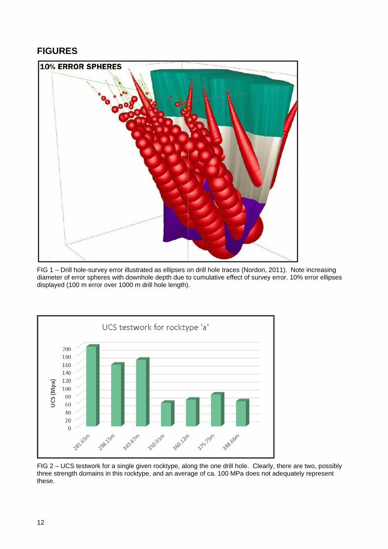
1. Logistical – (e.g. Drill hole location, both collar/wedge take-off depth and survey) These errors relate to confidence (uncertainty) in sample location which can be significant, particularly in deep mines. At depths of 800m and greater, volume difference (between minimum and maximum modelled volume of a geological entity) can be in the order of 25% within error ranges of 1m/1000m to 100m/1000m downhole (Nordin, 2011). Nordin (2011) displays locational error associated with downhole surveys as ellipses on the drill hole trace, with larger diameters with downhole depth representing the cumulative nature of survey error (Figure 1).
In this case, survey instrument type, and suitability for a given ore deposit (e.g. magnetic interference from orebody and/or host rocks), will be the main determinant of the amount of error.
3
2. Observational – (e.g. experience based data collection mechanisms) All human-based observations are subject to a degree of interpretation and error. Long-lived mining projects often have inherited historical data, numerous geological personnel as a factor of time (natural attrition) and transient consultants make observations of core and exposure, which can also be captured in the site database.
Consistency between data collectors is a universal issue, and techniques of advanced core photography and scanning (e.g. hyperspectral) of core have potential to augment human observations and assist in reducing the human-factor in data inconsistency.
3. Analytical – (e.g. instrument precision, sample selection issues (e.g. geochemical assay, Uniaxial Compressive Strength (UCS)) All analytical testwork methods carry a certain amount of uncertainty/error. This is a factor of natural variability, preparation/handling of sample material, and the machine-based error (e.g. repeatability error, drift). Bias in sample selection can be a significant source of error both by over-representation and omission, during the selection process or through the governing criteria of sample selection. An example of this, relevent to rock-mass characterisation, occurs during sample selection for UCS testwork. Naturally the test requires a solid piece of core, so there is bias toward intact core from the outset, but selection of the intact core pieces is often biased toward rock with fewer (or no) discontinuities (e.g. healed joints, veins) and directional bias of samples is often neglected. The directional bias is influenced by the angle between the core axis and any anisotropy in the rock which may include:
• bedding
• foliation/fabric
• jointing
• veins
• micro-fracturing
• preferred orientation of minerals or accumulations of minerals (alteration, mineralization).
Natural variability occurs in UCS testing of a given rock-type and this is illustrated in Figure 2. This series of UCS tests from a single lithological domain from the one drill hole demonstrates that other factors beyond the simplistic assignment of a rock-type, influence the measured rock-strength. This is likely due to one or more of the factors listed above.
An understanding of the directional impact of anisotropy in the rock-mass, on rock-strength, is required to determine the effects of the rotation of the local stress-field around the propagating cave. The aim should be to discern the influence of directional sample bias on the mechanisms involved in propagation and primary fragmentation, for the purposes of optimising cave performance.
4. Interpretational – (e.g. experience based and singular) Often, at an established mining operation, the geological model is the construct of a single operator. Although peer-review processes are common in mining technical departments and geological knowledge is accumulated during the exploration/project-assessment and development/mining initiation stages, there will always be ambiguity or non-uniqueness in geological modelling such that different operators may well have very different interpretations. This is usually a factor of the experience-level of the operator and any preconceived ideas/training/exposure which influence the interpretation process.
This source of uncertainty can be measured by probabilistic modelling of geological features. More challenging may be the likely issues in the communication of geological modelling error to, and receipt of these models and associated error limits by, engineering personnel at a given mining project. Similarly, the uncertainty related to interpolation of grade in a block model can be quantified by measuring the variance of model runs using differing model parameters, however resources are rarely reported with error margins including: ± ‘x’ tonnes and ± ‘y’ grade. Error, in the mining context, is likely perceived as a ‘flaw’ or ‘wrong’ rather than the variability associated with human (and machine) observations/measurements/calculations of any natural system.
Following on from these, error associated with performance models (mine and concentrator process simulations) whether deterministic or probabilistic in nature, compound these earlier ‘data’ and ‘information’ stage error sources.
4
Often, none of these are represented in the block model used for design purposes. The sometimes cumulative effect of uncertainty must be communicated to downstream customers, particularly after the geological model is ‘crystallized’ and accepted as the unique, or at least accepted, understanding of the deposit geology.
Adverse consequences, which may arise in a mining operation, are usually attempted to be resolved through re-interpretation, that is, the last stage of the data analysis.
Use of Geological Models in the Cave Design and Cave Establishment Stages Geological domains are morphed into geotechnical domains according to geotechnical observations from dominantly lithology based spatial domains. Limited geological observations survive this transformation and the emphasis is placed, thereafter, on semi-quantitative indices including RMR (Bieniawski, 1974, 1976), IRMR/MRMR (Laubscher and Jakubec, 2001), Q (Barton, Lien, and Lunde, 1974), and GSI (Marinos, Marinos, and Hoek, 1995). Structural geology information utilised in these stages is often limited to major fault models or more so, joints.
At the scale of the extraction-level of a block-cave mine, even with mapping available, ambiguity can exist in how to best connect observations, taking into account combinations of cross-cutting relationships, and build an interpretive layer of the geology of the mine level.
The non-uniqueness of interpretation of the structure is seldom addressed and is likely the most achievable application of probabilistic modelling of geological features. In doing this, structures would no longer be represented by explicit surfaces but as contiguous zones of three-dimensional cells with uncertainty/probability assigned via multiple simulations of the fault network geometry.
Anisotropy within the rocktypes is largely overlooked, to the detriment of any models of rock behaviour thereafter. Not only do rocktypes comprise anisotropy, drill hole orientation intersects this anisotropy variably which will also impact on testwork undertaken for design purposes. This anisotropy may occur as:
• Bedding (planar heterogeneous distribution of differing rock-types)
• Fabric/Foliation (preferred orientation at the grain/crystal size – can be the dominant planar discontinuity in some rocks)
• Alteration domains (heterogeneous distribution of mineralogy and/or assemblages, may cross-cut bedding [see above] or be focussed along bedding)
• Veining (present as planar contrasts in mineralogy which can be either weaker or stronger than the host rock-type, and may have alteration selvedges of weaker/stronger mineralogy also).
Anisotropy will materially affect the mechanisms associated with fracture propagation to the extent that the local orientation of ‘new’ fractures may be primarily controlled by features of anisotropy in the rock-mass, and the far-field stress tensor as the second-order control on fracture orientation.
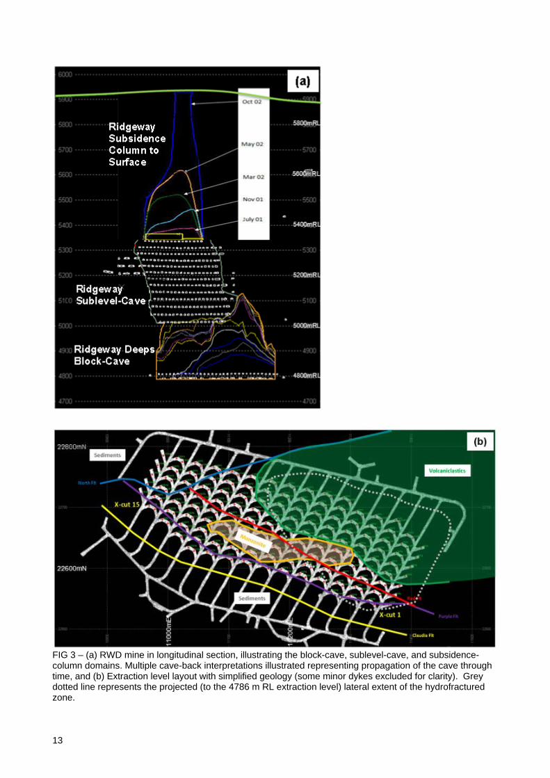
GEOLOGICAL INFERENCES FROM OPERATIONAL DATA An analysis of the Ridgeway Deeps (RWD) Block-Cave (Figure 3) was undertaken to determine how geology impacted on cave back propagation, with the aim of providing numerical modellers with key datatypes to be incorporated into forward-looking, innovative modelling platforms.
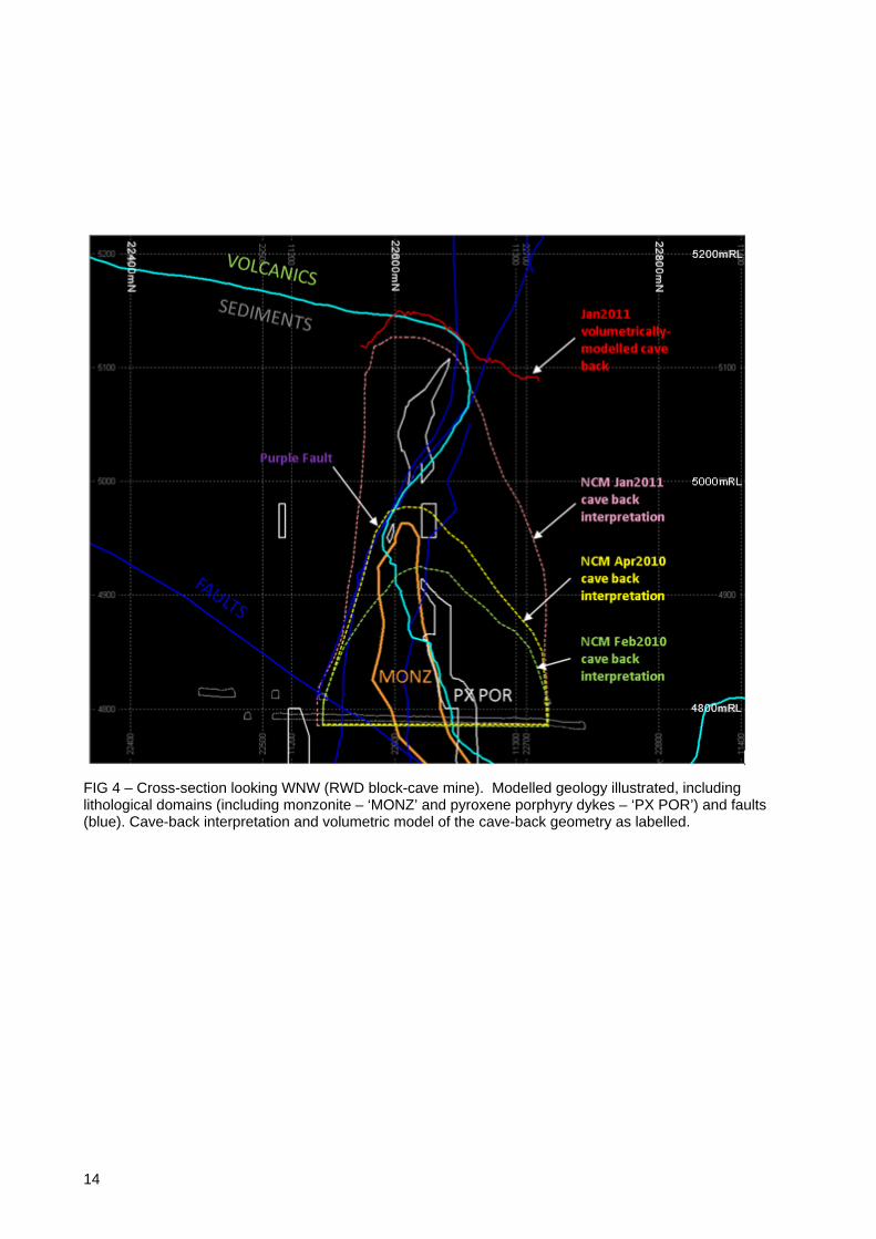
Ridgeway Deeps Block-cave is located beneath a pre-existing Sublevel-Cave (Figure 3a) and has footprint dimensions of approximately 450 m x 150 m (Figure 3b). The gross geology of the cave comprises a sequence of (meta)-sedimentary rocks, overlain by more competent volcaniclastic rocks, and intruded by monzonite, monzodiorite, and pyroxene porphyry dykes. In the cave-volume, the sedimentary/volcanic contact, normally gently dipping, is faulted and results in a steep juxtaposition of the rock units (Figure 4).
In terms of geological assessment of caving-processes, subsequent to initiation/under-cutting, a block-cave operates as a ‘blind’ system. That is, the mine technical personnel are no longer able to visually, or through the use of cavity measuring systems, observe the rock-mass response to mining activity. This is a unique situation and is the source of ambiguity in block-cave mining around the assessment of:
• primary fragmentation
5
• cave flow dynamics
• how closely coupled the processes of draw and propagation are for a given rock-mass/orebody
• cave-back location/geometry.
While methods to estimate the above parameters do exist, measurement remains problematic largely due to restriction of access and the large scale of the phenomena. Predictions of phenomena are also often based on retrospective analysis of other mining operations.
Some key areas of investigation, and assumed geological influences on propagation/fragmentation, included:
• Veining/vein-density: dependent on vein infill mineralogy and alteration selvedge. This need only be investigated if veining occurs in significant abundance at a given deposit.
• Fault characterisation: e.g. gouge, pug, healed, slickensided, planar etc. These will all behave differently when mining induced stress impacts on them, and are also dependent on the angle of interaction.
• Understanding of how the rotating and fluctuating mining-disturbed stress field will interact with geological features: what are the critical orientations and when? There is a time component involved as the change in stress field is related to cave propagation.
• Accurate domaining of lithological/alteration/structural domains. There will be variability within a single rocktype/lithology domain, does this variability have a material effect on cave performance?
Some of the items mentioned above require non-linear numerical modelling to ascertain the true impact on cave propagation, and the analysis therefore became internally circular.
In the case of veining, insufficient geotechnical testwork has occurred in the veined rock at RWD to determine what effect higher vein-density has on cave propagation and/or fragmentation. Visual observations on rocks in the draw-points (Brunton and Letts, 2011) indicate that the dominant sulphide hosting veins are not a weak discontinuity, and do not strongly influence secondary fragmentation, or the shape of rocks reporting to the drawpoint. The effect of the dominant, mineralized veining on cave propagation at RWD is still not well understood.
Empirical observations of fault characteristics (Chitombo et al., 2014) suggest important relationships with the distribution of mining-induced seismic activity, in ways perhaps unexpected. This is discussed further in subsequent sections of this document.
Macro-scale effects of Geology on Block-Cave Mining A series of cave-back interpretations, on an approximately monthly basis, provide the only means of resolving the effects of geology on propagation of the Ridgeway Deeps Block-cave. The nature of these interpretations, and assumptions involved, also introduces some uncertainty as to the accuracy of the cave-back location and geometry. The 3D interpretations are constructed from a combination of:
• observations of the distribution of micro-seismic events
• testing of open-holes into the cave-back/cave-‘path’
• draw location and intensity
• numerical modelling prediction.
The cave back geometries were compared against the known geological features to determine if any rock-types, faults, structural domains, and zones of alteration were instrumental in affecting the geometry of the cave-back, or rate of propagation (Figure 4).
For the purposes of evaluating the effects of geological features on cave propagation, RWD block-cave was perhaps too ‘well-behaved’ to isolate those geological features which may have had a material effect on cave performance. This does not negate other deposits from being more or less susceptible to problematic propagation dependent on the strength of host rocks, structure density and orientation. However, there were
6
indications that, under different circumstances (e.g. stress field, undercutting sequence), the geology could impact significantly on propagation.
Early in the propagation-history of RWD, the cave margins/flanks were strongly influenced by the geometry of major faults to the extent that the southern flank of the cave-back was controlled by the ‘Purple Fault’ (see Figure 4). The geometries demonstrated by the cave-back interpretations suggest the cave propagation ‘pauses’ for a period of time, likely to be of the order of the monthly resolution of the periodic interpretations. After this brief period with the cave semi-arrested on the Purple Fault, propagation continued through into the ‘sedimentary’ rock unit above the Purple Fault (Figure 4).
Major faults are a key feature communicated and transferred by way of models from geologists to mining and geotechnical engineers. Major faults have strike-length in the order of >100 m, up to those transgressing the full footprint of the cave, and can be adequately spatially modelled using drilling data and the available development mapping. Characterisation of the fault types by width, fill-type, mineralogy etc is important to better understanding the role faults play in mechanisms involved in cave-propagation.
The effect of contrasting rheology of the sedimentary and volcanic lithologies manifest as a change in cave asymmetry prior to and subsequent to propagation through the Purple Fault. Global RMR mean values of the volcanics and sedimentary units are similar at 61 and 53.4, respectively (Lett, 2009). In the volcanic-dominated domain, the cave maintained a symmetrical dome-like shape. However, on propagating through the Purple Fault, the southern wall of the cave steepened to become sub-vertical, and the cave became asymmetrical in cross-section. This was inferred to be a result of the sedimentary unit having more discontinuities (including bedding) and achieving higher propagation rates compared to the volcanics. Analysis of joint sets indicates distinct orientations in the sedimentary unit compared to the volcanics and intrusives, potentially suggesting a significant influence of bedding and or cleavage in the development of joint-scale discontinuities (Chitombo et al., 2014). Heterogeneity of the rock-types in the immediate cave back clearly have a measurable, but not detrimental, effect on the propagation of the RWD block-cave.
The rheological contrast across this faulted contact worked to the advantage of the RWD block-cave, but could well have effected a stall if the contrast was inverted. Rheological contrast effected arrest of the cave crown temporarily, earlier in the mine-life, and is implicit in the arrest of the cave peak as recorded by the final cave back geometry (Figure 4). The rheological contrast between the sedimentary and volcaniclastic rock-types is accentuated by the gently dipping contact between the two units, at the location of the cave peak (Figure 4).
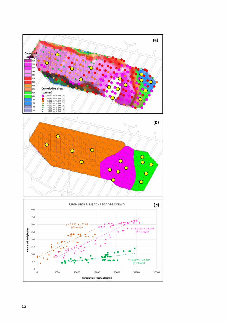
Despite the observations of how geology did affect the cave propagation, the effects of draw account well for the interpreted gross geometry of the RWD cave (Chitombo et al., 2014), indicating that an underlying relationship between draw and propagation, via the air-gap or lack thereof, occurs and can be measured/quantified (Figure 5).
Preconditioning of part of the cave volume, comprising volcanics with assumed reduced caveability, was undertaken utilising hydrofracturing. The cave was also initiated in the North-east corner of the footprint, dominated by this rock-type (Figure 3b).
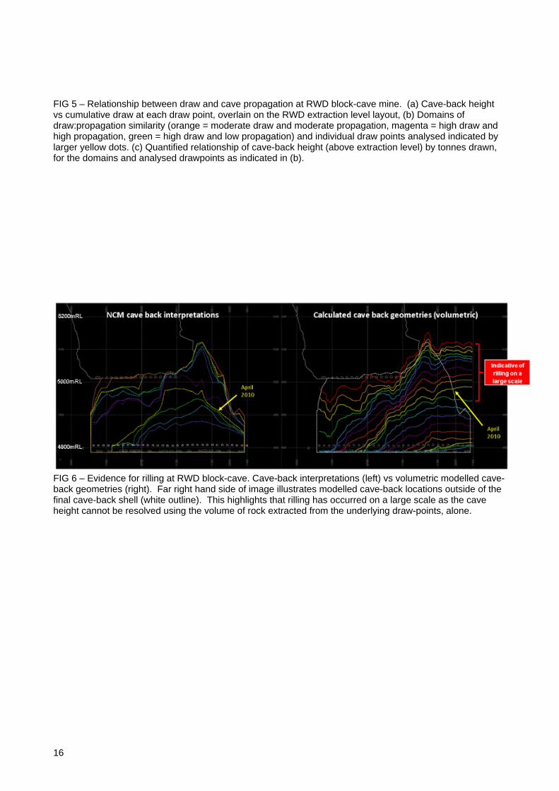
A partial stall occurred whereby the corner of the cave dominated by volcanics failed to maintain caving rates in line with the rest of the footprint, even with higher draw-rates in the affected area (Figure 5a). Higher-draw likely exacerbated the phenomenon by effecting rilling from more central areas of the cave to the extremity where the volcanics had stalled. The result was, therefore, higher rates of propagation in areas away from the targeted stall zone (Figure 5a-c). The geological domains have a measurable effect on the draw:propagation relationship (Figure 5c). Figure 6 illustrates the difference between the cave back interpretations as supplied by site personnel, and the cave-back height calculated via volumetric modelling. Departures of the volumetric modelled surface, to the cave-back interpretations, are suggestive of rilling on a large scale. It is observed that the geology has had an indirect effect on cave-flow, via the partial stall in the cave propagation and the interventions to correct/manipulate the cave back geometry through the draw schedule. Lithological controls (encompassing inherent rock-type specific strength, and discontinuity type and spacing) on caveability are the key criteria where ‘geology’ impacts on the success of a caving operation.
Mining Induced Seismicity as an Indicator of Geological Domains in the Cave Volume and Cave Back. Although the observations of cave-induced seismic activity come too late to modify design, or operation in some cases, and the data is interpreted largely in retrospect; interpretations of seismic event distribution may
7
be useful in determining the mining strategy for a lower lift on a cave, or well ahead of the cave-front in a panel-cave operation.
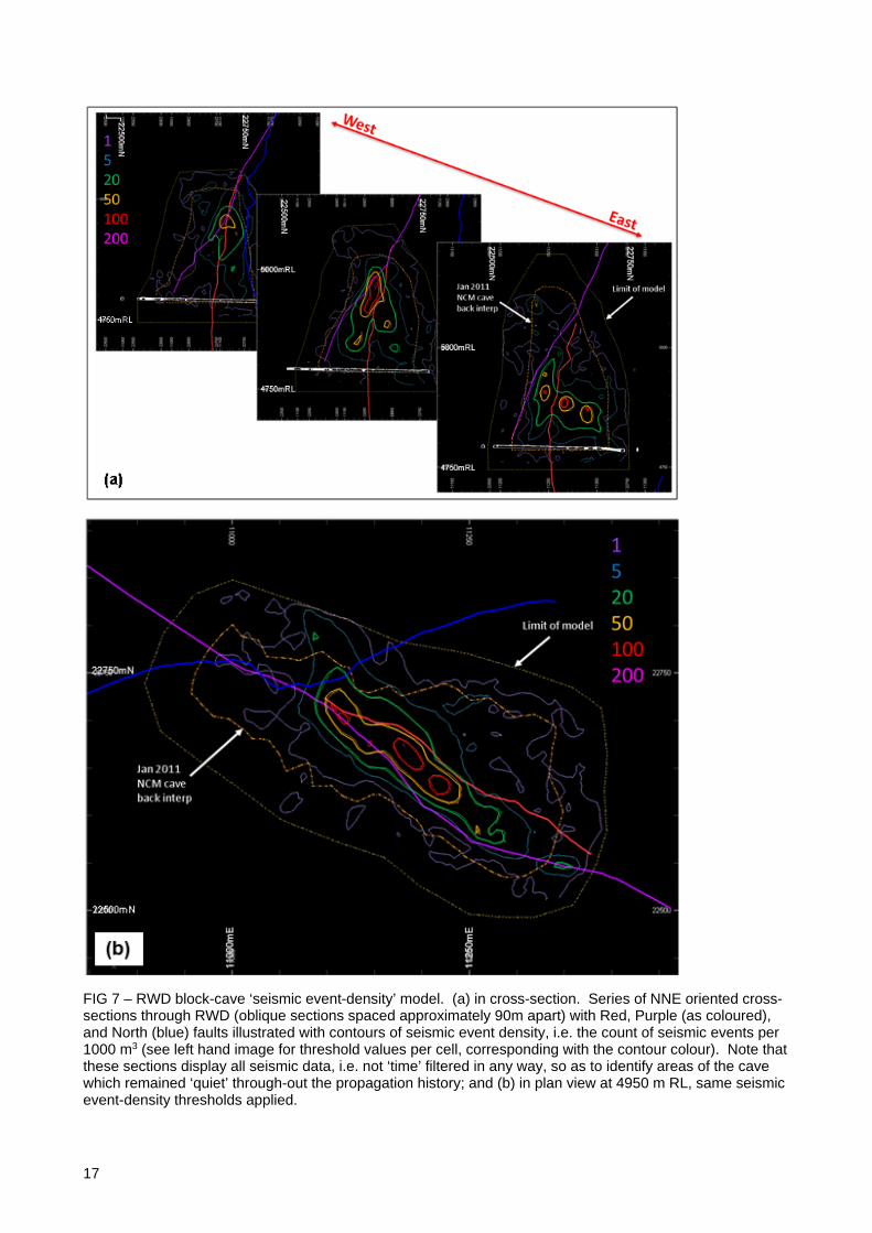
Microseismic events in the cave-back of the RWD block-cave were heterogeneously distributed due to geological factors (Figure 7). Retrospective analysis of the ‘seismic event-density’ (Figure 7), a method of quantifying the distribution of seismicity by a count of events per unit volume (1000 m3, equivalent to 10 x 10 x 10 m cell size consistent with the block model), has been applied to the comprehensive RWD dataset and reviewed in the context of the modelled mine geology. No time filtering has been applied in this analysis as presented here, although this has been undertaken as part of a broader research project into the RWD block-cave (Chitombo et al., 2014). Holistic approach to analysis of the seismicity, i.e. without time-filtering, enables the recognition of areas of the cave that remained seismically ‘quiet’ throughout the propagation history. This is important to recognize given the fundamental relationship of the seismogenic zone in the propagation process.
It is observed that two distinct domains of seismicity occur in the RWD cave-volume (Figure 7). These are primarily within a fault corridor broadly coincident with the long axis of the cave, and at the intersection of the faults involved; and a secondary distribution which has shown to be at least spatially related to the hydrofractured domain in the cave, as represented by the two dominant trends in seismic-density in Figure 7a. The area subject to hydrofracturing is broadly consistent with the domain of volcaniclastics located in the northeastern corner of the cave footprint (Figure 3b).
The bounding faults to seismicity at RWD are interpreted as aseismic faults (Chitombo et al., 2014) and, at the scale of the analysis, appear to envelop seismic activity but not focus it. Characterisation of faults has partially explained the phenomenon as a function of fault width and fill. Intuitively, wider gouge-rich faults are more likely to accommodate slip as a passive, ‘quiet’ event, as opposed to tight faults with little or no fill. Supporting this, a direct relationship was observed between RQD and seismic density (i.e. higher RQD corresponds with higher seismic density), and an inverse relationship between fracture frequency and seismic density (higher fracture frequency corresponds with lower seismic density) (Chitombo et al., 2014).
Accurate characterisation of major, and intermediate faults, is critical to comprehensive understanding of the stress field:rock interaction at the cave scale. This information, however, will only be useful if the retrospective observations can be applied in a forward looking predictive capability. Prediction of domains of contrasting seismic activity in the planned cave-column may influence the application, both location and type, of preconditioning activities. That is, if seismic prediction enabled identification of litho-structural domains where autogenic caving is probable, or where assisted ground preparation through pre-conditioning is required to induce seismogenic activity.
Unmodelled Geological Features – Their Effect on the Block Cave Operation, and Issues Associated with Their 3D Representation Unmodelled features are distinct from ‘unknown’ features encountered during the mine development and operation. Unknown features are dominantly a function of drill hole spacing and orientation, however interpretational error is a possible cause.
Unmodelled features are those geological features which are observed but are not represented/captured in geological models. This is often a function of limited observation, which may also be due to spatial orientation of the feature with respect to the dominant drilling direction. This phenomenon can cause bias in the collection of geotechnical data where a dominant orientation of drive occurs in a given extraction level/undercut layout.
Even still, where intermediate structures (with strike length of 10-100m) are mapped, they are likely under-represented or not represented in geological models due to too-few located points to build a high-confidence geological surface/3D model.
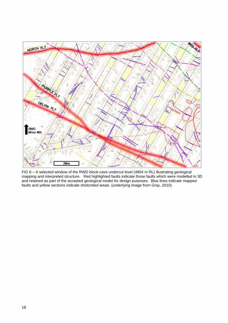
An example of this is illustrated in Figure 8, where a portion of the RWD undercut level development geological mapping is shown. Those structures which made it through to 3D modelling and inclusion in the accepted geological model are highlighted. Rationalisation of the map data occurs such that only the major structures are represented either to allow easier transfer/communication to downstream customers, or because downstream modelling processes are unable to handle the complexity of multi-dimensional structural layers.
This is problematic, as these structures can be critical to appropriately defining grade distribution, can impact on geotechnical stability of development and other mined voids, and are likely critical in the mechanisms associated with cave propagation and primary fragmentation. The relationship of intermediate structure to seismic activity is largely anecdotal, however it is easy to visualize a network of three-dimensional intermediate
8
structure in the fault-bounded seismic corridor illustrated in Figure 7, especially in light of the observations of geological reality in Figure 8. Intermediate structures are more likely to be tight structures with lesser fill and may be destined for localization of seismic activity given that the domain of intermediate structure will likely be bound by larger, weaker fault zones (Figure 7 & 8).
The issues with appropriate representation of structure at all scales are not limited to cave mines. This issue plagues mines of all scales and demonstrates a gap in how we represent this intermediate scale of geological data and information in 3D models.
It is therefore of importance to overcome the challenge of capturing intermediate structure. Probabilistic modelling of deposit geology, in particular the multi-dimensional structural features, can identify domains where a specific orientation of structure is likely, but the location of the inferred structures is derived from geometric simulations (utilising multiple-point statistics or similar) and quantified through a probability ranking. While a high-confidence location of intermediate structure is not yielded from this method, it has potential application in informing broader strategies around ground-support and numerical modelling of geomechanical behaviour, both of which requiring knowledge of the structures in a continuum-style approach. With its obvious draw-backs, this method is still better than complete lack of representation of intermediate structure in the models used for design purposes. The proposed methodology also goes beyond that employed in discrete fracture network (DFN) modelling where orthogonal joint simulation is not geologically representative.
There is an aim, in the underground mining industry, to increase turnaround times for drilling through to geological interpretation and modelling, and ensuing resource updates. Embodied in this, is the desire to drill less, and therefore reduce costs as well as time. From the geologist’s perspective, any increase in drill-spacing equates to reduced observation of the volume of rock, and less certainty in any derived models whether they be geological, geotechnical, or numerical modelling of a process. Adequate geochemical sampling of the orebody will always be the key driver to define drill-spacing to reduce uncertainty of the spatial location and tenor of mineralisation, and to satisfy reporting codes. The decision to reduce the amount of drilling (increase drill hole spacing) cannot be made through a cost-driven exercise alone unless the following risks can be accommodated by the mining and processing functions:
• Higher uncertainty in the location and quality of mineralisation.
• Higher likelihood that significant structures (faults, fracture domains, folds) will not be identified prior to mining. These structures may have detrimental effect on underground development and successful initiation of the cave.
• Less confidence in the characterisation of the rock-mass for assessment of caveability and fragmentation prediction.
While the application of geophysical methods, likely to be down-hole techniques (e.g. cross-hole seismic, ground-penetrating radar) for the deep mass-mining operation, has merit in informing on inter-drill hole geology; it is unlikely to deliver a step-change in either costs or timeframe for resource definition. Take-up of geophysics as applied to underground metalliferous mining is well behind other sectors of the mining industry and perhaps only through increasing the value-proposition to involve both sensing (structure and lithology delineation) and monitoring capability (cave-back location and geometry), as a long-lived data-collection platform, will it be applied in earnest in underground mass-mining.
What Should we do Differently to Better Utilise Geological Knowledge and Observations in the Mine Design and Optimisation Process? Mineralogy, and the texture (spatial distribution) of mineralogy is fundamental to characterising rocks and determines the physical properties, and therefore process-response, of rock-types through the mining and minerals processing activities.
Understanding mineralogy and its control on brittleness in application to mining (i.e. the spectrum from drives squeezing > stable > rock bursts) may complement testwork derived characterization of rock-types. It is necessary to identify the key minerals, comprised in the deposit geology, and their abundance and spatial distribution; and any relationship to measured parameters including Poisson’s Ratio and Young’s Modulus. While this is measured as part of geotechnical testwork (Poisson’s Ratio and Young’s Modulus), how is this data used and resolved against the changes to the stress-field (orientation and magnitude) due to mining?
Mineralogy is also key to understanding the reactivity of material in the cave, whether the risk involved is due to:
9
• re-cementing of fragments
• rapid oxidation
• solubility/groundwater interaction (dissolution of minerals, e.g. calcite; or swelling minerals, e.g.Laumontite)
• health and safety of mine workers (radioactive, fibrous, chemical hazards)
• spontaneous combustion
• clay/fines generation and the risk of mud-rushes/dilution
• downstream processing effects (deleterious elements).
We should embrace the uncertainty which exists naturally in the data. This should not serve as means to a disclaimer in the event that an interpretation is not 100% correct, but to better communicate alternative interpretations that can be reasonably made from the data. No one interpretation/model is completely correct and it is folly to use a singular geological model without recognizing this. Geological features, due to location and orientation uncertainty, are best represented by probability mapping of the potential interpretations/simulations of the potential geometries. The main hurdles to adoption of this is communication of uncertainty amongst technical personnel.
CONCLUSIONS Uncertainties in geological data from block-cave mines are compounded by the lack of development from which to calibrate observations and models constructed from drill hole data. Mapped observations are the highest confidence data that can be obtained and are often used to confirm interpretations made from drill hole data and, through inclusion in the model, improve the overall confidence. In a Block-Cave operation, geologists are asked to produce high-confidence models similar to any other mining operation, but with greatly limited access to geological exposure to calibrate these models. Intuitively, other methods of geological detection/sensing should be applied to counteract the lack of exposure, e.g. geophysics; however this is rarely applied systematically in metalliferous operations. The value proposition for collecting geological data is fundamental, this data (knowledge of the rocks) is utilised in all downstream processes and any reduction of the primary data collection will pass additional risk to mining processes (stability, caveability, fragmentation prediction) and minerals processing activities (crushability, grindability, recovery predictions).
An analysis of the Ridgeway Deeps Block-Cave mine and subsequent inferred geological controls on the ‘blind’ processes in Block-Cave mining demonstrate the link between geological data and cave propagation. Geology does have a measurable effect on cave propagation and the challenge is to determine whether the geological effects will be beneficial or detrimental to the caving operation. The observations of the study of RWD, and appropriate sources from the literature, will be used to inform new methods of numerically modelling and prediction of cave propagation. This process is an iterative loop, as we will learn more about the role of geological features in determining caving outcomes through the simulation process, with a desirable outcome being the determination of critical data required to optimise caving predictive models.
Redaction of geological information (observations, data, interpretations, and concepts) to deliver a single geological model for use by customer disciplines is a necessary process in the traditional mine planning lifecycle. This inherently results in loss of resolution and/or data that is used in any derived models, including numerical simulations of unit processes. Whether the loss of resolution of data, exclusion of data, or the biased modelling of data (through singular 3D model creation) will have a material effect on the operation will only be determined through experience (worst case scenario) or through rigorous multi-disciplinary communication. This requires openness to ideas/concepts, while remembering that we are trying to deconstruct the science of a natural system into units that can be estimated/quantified/modelled, for the purposes of mineral extraction. Silo creation around geology, geotechnical, mining engineering, metallurgical disciplines; can make the communication of ideas complicated, but should all start with a common unit, ‘the rocks’. Each discipline is interested in a process response of the rock and although there is the desire to each characterise the rock differently (rock strength/hardness being the type example), the commonality between cross-disciplinary observations should be exploited rather than focus on the difference. This is embodied in orebody knowledge/deposit knowledge/geomet programmes, which often have geologists as the custodian of the process, but draw insight from all disciplines, particularly early in the project lifecycle when key drivers of process performance are yet to be determined.
10
Attention has been drawn to two scales of information where geological data and information is not adequately captured, and/or not adequately utilised by downstream customers:
• textural anisotropy
• intermediate structure
These are examples of data where good knowledge/interpretation/rock-response information are collected and accumulate through resource establishment and mine development, but capturing of the data spatially or predicting 3D distribution is problematic and difficult. This data falls through the gap of traditional model generation. If the data is immaterial to unit processes in the mining and minerals processing functions, then no change is required. However, if these data types can be shown to have a process-critical effect, then the challenges of representation in 3D models or designing numerical modelling systems to incorporate the data, will need to be overcome. It is likely that, as block-cave mining is applied to strongly deformed and complex geological systems, more comprehensive utilisation of the geological data that is collected, will be required. It is possible that new/additional data types will be required to best represent new mining scenarios and the response of the rock-mass to the same.
ACKNOWLEDGEMENTS This paper presents some of the findings from the ‘Geology and Mass Mining’ Research Project (2013-2015) undertaken by the WH Bryan Research Centre (UQ-Sustainable Minerals Institute). This project is funded by industry sponsors (Newcrest Mining Limited, Glencore – Mount Isa Mines, Anglo American plc) and the Queensland Government Smart Futures Fund (2011).
REFERENCES Barton, N, Lien, R, and Lunde, J, 1974. Engineering classification of rock masses for design of tunnel support. Rock
Mechanics, 6(4): 189-236.
Bienawski, ZT, 1974. Geomechanics classification of rock masses and its applications in tunnelling. Proceedings 3rd International Congress on Rock Mechanics, Denver, 2A: 27-32. National Academy of Sciences: Washington, D.C.
Bienawski, ZT, 1976. Rock mass classification in rock engineering. Exploration for Rock Engineering. (Ed: ZT Bienawski), 1:97-106. Balkema: Cape Town.
Brunton, I, and Lett, J, 2011. Characterisation of Block Forming Discontinuities at Ridgeway Deeps. Unpublished company report – Newcrest Mining Limited.
Chitombo, G, Murphy, T, Puscasu, R, and Webster, A (ed), 2014. Geology and Mass Mining Project - Second Technical Progress Report. Unpublished report.
Gray, D, 2010. Comments on Ridgeway Deeps Structural Interpretation. Unpublished consultant’s report to Newcrest Mining Limited.
Hoek, E, 1994. Strength of rock and rock masses. ISRM News J, 2(2): 4-16.
Laubscher, DH, and Jakubec, J, 2001. The MRMR rock mass classification for jointed rock masses. Underground Mining Methods: Engineering Fundamentals and International Case Histories, (Ed: WA Hustrulid and RL Bullock), 475-481. Society for Mining, Metallurgy and Exploration: Littleton, Colorado.
Lett, J, 2009. Geotechnical Block Model 2009 – Ridgeway Deeps. Unpublished company report – Newcrest Mining Limited.
Marinos, V, Marinos, P, and Hoek, E., 1995. The geological strength index: applications and limitations. Bull Eng Geol Environ, v64, 55-65.
Nordin, W, 2011. The Effect of Downhole Survey Uncertainty on Modelled Volume. [online] www.geovia.com. Available at: http://www.geovia.com/resources/white-papers/gems [Accessed 16 Oct. 2015].
11
FIGURE CAPTIONS FIG 1 – Drill hole-survey error illustrated as ellipses on drill hole traces (Nordon, 2011). Note increasing diameter of error spheres with downhole depth due to cumulative effect of survey error. 10% error ellipses displayed (100 m error over 1000 m drill hole length).
FIG 2 – UCS testwork for a single given rocktype, along the one drill hole. Clearly, there are two, possibly three strength domains in this rocktype, and an average of ca. 100 MPa does not adequately represent these.
FIG 3 – (a) RWD mine in longitudinal section, illustrating the block-cave, sublevel-cave, and subsidence-column domains. Multiple cave-back interpretations illustrated representing propagation of the cave through time, and (b) Extraction level layout with simplified geology (some minor dykes excluded for clarity). Grey dotted line represents the projected (to the 4786 m RL extraction level) lateral extent of the hydrofractured zone.
FIG 4 – Cross-section looking WNW (RWD block-cave mine). Modelled geology illustrated, including lithological domains (including monzonite – ‘MONZ’ and pyroxene porphyry dykes – ‘PX POR’) and faults (blue). Cave-back interpretation and volumetric model of the cave-back geometry as labelled.
FIG 5 – Relationship between draw and cave propagation at RWD block-cave mine. (a) Cave-back height vs cumulative draw at each draw point, overlain on the RWD extraction level layout, (b) Domains of draw:propagation similarity (orange = moderate draw and moderate propagation, magenta = high draw and high propagation, green = high draw and low propagation) and individual draw points analysed indicated by larger yellow dots. (c) Quantified relationship of cave-back height (above extraction level) by tonnes drawn, for the domains and analysed drawpoints as indicated in (b).
FIG 6 – Evidence for rilling at RWD block-cave. Cave-back interpretations (left) vs volumetric modelled cave-back geometries (right). Far right hand side of image illustrates modelled cave-back locations outside of the final cave-back shell (white outline). This highlights that rilling has occurred on a large scale as the cave height cannot be resolved using the volume of rock extracted from the underlying draw-points, alone.
FIG 7 – RWD block-cave ‘seismic event-density’ model. (a) in cross-section. Series of NNE oriented cross-sections through RWD (oblique sections spaced approximately 90m apart) with Red, Purple (as coloured), and North (blue) faults illustrated with contours of seismic event density, i.e. the count of seismic events per 1000 m3 (see left hand image for threshold values per cell, corresponding with the contour colour). Note that these sections display all seismic data, i.e. not ‘time’ filtered in any way, so as to identify areas of the cave which remained ‘quiet’ through-out the propagation history; and (b) in plan view at 4950 m RL, same seismic event-density thresholds applied.
FIG 8 – A selected window of the RWD block-cave undercut level (4804 m RL) illustrating geological mapping and interpreted structure. Red highlighted faults indicate those faults which were modelled in 3D and retained as part of the accepted geological model for design purposes. Blue lines indicate mapped faults and yellow sections indicate shotcreted areas. (underlying image from Gray, 2010)
12
FIGURES
FIG 1 – Drill hole-survey error illustrated as ellipses on drill hole traces (Nordon, 2011). Note increasing diameter of error spheres with downhole depth due to cumulative effect of survey error. 10% error ellipses displayed (100 m error over 1000 m drill hole length).
FIG 2 – UCS testwork for a single given rocktype, along the one drill hole. Clearly, there are two, possibly three strength domains in this rocktype, and an average of ca. 100 MPa does not adequately represent these.
13
FIG 3 – (a) RWD mine in longitudinal section, illustrating the block-cave, sublevel-cave, and subsidence-column domains. Multiple cave-back interpretations illustrated representing propagation of the cave through time, and (b) Extraction level layout with simplified geology (some minor dykes excluded for clarity). Grey dotted line represents the projected (to the 4786 m RL extraction level) lateral extent of the hydrofractured zone.
14
FIG 4 – Cross-section looking WNW (RWD block-cave mine). Modelled geology illustrated, including lithological domains (including monzonite – ‘MONZ’ and pyroxene porphyry dykes – ‘PX POR’) and faults (blue). Cave-back interpretation and volumetric model of the cave-back geometry as labelled.
15
16
FIG 5 – Relationship between draw and cave propagation at RWD block-cave mine. (a) Cave-back height vs cumulative draw at each draw point, overlain on the RWD extraction level layout, (b) Domains of draw:propagation similarity (orange = moderate draw and moderate propagation, magenta = high draw and high propagation, green = high draw and low propagation) and individual draw points analysed indicated by larger yellow dots. (c) Quantified relationship of cave-back height (above extraction level) by tonnes drawn, for the domains and analysed drawpoints as indicated in (b).
FIG 6 – Evidence for rilling at RWD block-cave. Cave-back interpretations (left) vs volumetric modelled cave-back geometries (right). Far right hand side of image illustrates modelled cave-back locations outside of the final cave-back shell (white outline). This highlights that rilling has occurred on a large scale as the cave height cannot be resolved using the volume of rock extracted from the underlying draw-points, alone.
17
FIG 7 – RWD block-cave ‘seismic event-density’ model. (a) in cross-section. Series of NNE oriented cross-sections through RWD (oblique sections spaced approximately 90m apart) with Red, Purple (as coloured), and North (blue) faults illustrated with contours of seismic event density, i.e. the count of seismic events per 1000 m3 (see left hand image for threshold values per cell, corresponding with the contour colour). Note that these sections display all seismic data, i.e. not ‘time’ filtered in any way, so as to identify areas of the cave which remained ‘quiet’ through-out the propagation history; and (b) in plan view at 4950 m RL, same seismic event-density thresholds applied.
18
FIG 8 – A selected window of the RWD block-cave undercut level (4804 m RL) illustrating geological mapping and interpreted structure. Red highlighted faults indicate those faults which were modelled in 3D and retained as part of the accepted geological model for design purposes. Blue lines indicate mapped faults and yellow sections indicate shotcreted areas. (underlying image from Gray, 2010)