Embed Size (px)
Citation preview
Lakehaven Utility District Sanitary Sewer Specifications (07/2002) SPEC-TOC-1
LAKEHAVEN UTILITY DISTRICT
SANITARY SEWER SPECIFICATIONS
TABLE OF CONTENTS
SECTION PAGE STATEMENT OF DESIGN CRITERIA SPEC-DC-1 DEFINITIONS SPEC-DEF-1 1. CLEARING 1.1 General...............................................................................................................SPEC-1-1 1.2 Pavement Removal.............................................................................................SPEC-1-2 1.3 Lawn Removal....................................................................................................SPEC-1-2 1.4 Disposal of Clearing Materials.............................................................................SPEC-1-2 1.5 Construction Waste Disposal ..............................................................................SPEC-1-2 2. TEMPORARY EROSION AND SEDIMENTATION CONTROL 2.1 Existing Drainage Facilities ..................................................................................SPEC-2-1 2.2 Matting, Netting and the Use of Straw.................................................................SPEC-2-1 2.3 Slope Protection and Lawn Establishment............................................................SPEC-2-3 2.4 Silt Fencing.........................................................................................................SPEC-2-6 2.5 Work In and Near Wetlands, Streams and Tidelands...........................................SPEC-2-6 3. EARTHWORK - SEWERS 3.1 General...............................................................................................................SPEC-3-1 3.2 Trenching............................................................................................................SPEC-3-3 3.3 Foundation Material and Placement.....................................................................SPEC-3-4 3.4 Bedding Material and Placement .........................................................................SPEC-3-5 3.5 Backfill...............................................................................................................SPEC-3-7 3.6 Temporary Roadways.........................................................................................SPEC-3-10 3.7 Additional Unclassified Excavation......................................................................SPEC-3-11 3.8 Flaggers, Barricades and Signs............................................................................SPEC-3-11 3.9 Public Convenience and Safety............................................................................SPEC-3-11 3.10 One-Way Piloted Traffic Control Through Construction Zone ............................................................................................SPEC-3-12 3.11 Construction and Maintenance of Detours ...........................................................SPEC-3-12 3.12 Fills and Embankments........................................................................................SPEC-3-13 3.13 Existing Facilities.................................................................................................SPEC-3-13
TABLE OF CONTENTS (Continued)
SPEC-TOC-2 Sanitary Sewer Specifications (07/2002) Lakehaven Utility District
SECTION PAGE 4. PIPELINE CONSTRUCTION 4.1 General...............................................................................................................SPEC-4-1 4.2 Material List .......................................................................................................SPEC-4-1 4.3 Pipe Material......................................................................................................SPEC-4-2 4.4. Piping Accessories..............................................................................................SPEC-4-7 4.5 Pipe Laying.........................................................................................................SPEC-4-7 4.6 Service Fittings and Side Sewers.........................................................................SPEC-4-8 4.7 Jacking or Augering Construction........................................................................SPEC-4-9 4.8 Groundwater Surge Relief Lines..........................................................................SPEC-4-13 5. MANHOLE CONSTRUCTION 5.1 General...............................................................................................................SPEC-5-1 5.2 Material List .......................................................................................................SPEC-5-1 5.3 Materials ............................................................................................................SPEC-5-1 6. PIPELINE TESTING 6.1 General...............................................................................................................SPEC-6-1 6.2 Testing of Gravity Pipelines .................................................................................SPEC-6-1 6.3 Testing of Pressure Pipelines ...............................................................................SPEC-6-6 6.4 Testing of Manholes............................................................................................SPEC-6-6 6.5 Television Inspection...........................................................................................SPEC-6-7 7. RESTORATION 7.1 General...............................................................................................................SPEC-7-1 7.2 Temporary Surfacing and Maintenance................................................................SPEC-7-1 7.3 Pavement Restoration.........................................................................................SPEC-7-2 7.4 Landscaping Restoration.....................................................................................SPEC-7-74 7.5 Monument Restoration........................................................................................SPEC-7-78 7.6 Removal and Reinstall Existing Fences.................................................................SPEC-7-78 7.7 Weighing ............................................................................................................SPEC-7-78 7.8 Adjust Manholes, Catch Basins & Valve Boxes to Grade ................................................................................................SPEC-7-79 7.9 Restoration of Unimproved Areas .......................................................................SPEC-7-79 8. CLEANUP 8.1 General...............................................................................................................SPEC-8-1 8.2 Cleanup..............................................................................................................SPEC-8-1 8.3 Protection of Work.............................................................................................SPEC-8-2
TABLE OF CONTENTS (Continued)
Lakehaven Utility District Sanitary Sewer Specifications (07/2002) SPEC-TOC-3
SECTION PAGE 9. MEASUREMENT AND PAYMENT 9.1 Preliminary General Information...........................................................................SPEC-9-1 9.2 Construction.......................................................................................................SPEC-9-2 9.3 Bid Items/General...............................................................................................SPEC-9-2 9.4 Bid Items/Trench Excavation, Bedding, Backfill and Restoration..........................SPEC-9-4 9.5 Bid Items/Gravity Sewer Pipe and Augered Casings ............................................SPEC-9-9 9.6 Bid Items/Standard Manholes, Clean-outs and Manhole Drops............................SPEC-9-12 10. GENERAL REQUIREMENTS FOR PUMP STATIONS 10.1 Summary of Work..............................................................................................SPEC-10-1 10.2 Regulatory Requirements.....................................................................................SPEC-10-1 10.3 Abbreviations .....................................................................................................SPEC-10-2 11. SITE WORK 11.1 Site Preparation..................................................................................................SPEC-11-1 11.2 Earthwork ..........................................................................................................SPEC-11-2 11.3 Trenching, Backfilling and Compaction................................................................SPEC-11-4 11.4 Excavation Shoring .............................................................................................SPEC-11-4 11.5 Dewatering.........................................................................................................SPEC-11-5 11.6 Chainlink Fencing................................................................................................SPEC-11-6 11.7 Landscaping .......................................................................................................SPEC-11-7 11.8 Flaggers, Barricades and Signs............................................................................SPEC-11-10 12. CONCRETE AND FINISHING 12.1 Cast-In-Place Concrete ......................................................................................SPEC-12-1 12.2 Reinforcing Steel.................................................................................................SPEC-12-25 12.3 Concrete Finishes ...............................................................................................SPEC-12-28 12.4 Epoxy Grout.......................................................................................................SPEC-12-32 12.5 Cast-In-Place Reinforced Concrete Pump Station...............................................SPEC-12-33 12.6 Precast Reinforced Concrete Pump Station.........................................................SPEC-12-36 12.7 Confined Space Rescue and Retrieval System.....................................................SPEC-12-38 12.8 Access Doors.....................................................................................................SPEC-12-39 13. MECHANICAL EQUIPMENT 13.1 General Equipment and Mechanical Requirements ...............................................SPEC-13-1 13.2 Non-Clog Submersible Sewage Pumps...............................................................SPEC-13-12
TABLE OF CONTENTS (Continued)
SPEC-TOC-4 Sanitary Sewer Specifications (07/2002) Lakehaven Utility District
SECTION PAGE 14. PIPING AND ACCESSORIES 14.1 Pipe, Fittings, and Accessories ............................................................................SPEC-14-1 14.2 Valves and Accessories ......................................................................................SPEC-14-7 14.3 Pipe Saddles.......................................................................................................SPEC-14-13 15. ELECTRICAL SYSTEMS 15.1 General Electrical Requirements ..........................................................................SPEC-15-1 15.2 Raceways...........................................................................................................SPEC-15-4 15.3 Wire and Cable ..................................................................................................SPEC-15-7 15.4 Service Equipment ..............................................................................................SPEC-15-10 15.5 Over-Current Protective Devices ........................................................................SPEC-15-11 15.6 Subpanel and Transformer ..................................................................................SPEC-15-13 15.7 Control Panel and Control Devices......................................................................SPEC-15-14 15.8 Telemetry...........................................................................................................SPEC-15-19 15.9 Operation & Maintenance Manuals and Spare Parts............................................SPEC-15-21 16. STANDBY ENGINE-GENERATOR SYSTEMS 16.1 Standby Engine-Generator Sets...........................................................................SPEC-16-1 16.2 Automatic Transfer Switch..................................................................................SPEC-16-14 17. MISCELLANEOUS EQUIPMENT 17.1 Waterproofing with Special Coatings...................................................................SPEC-17-1 17.2 Protective Coatings.............................................................................................SPEC-17-3 17.3 Miscellaneous Metals..........................................................................................SPEC-17-7 17.4 Galvanizing .........................................................................................................SPEC-17-9 17.5 Plastic Fabrications .............................................................................................SPEC-17-11 17.6 Specialties ..........................................................................................................SPEC-17-12 17.7 Identifying Devices..............................................................................................SPEC-17-14 APPENDICES
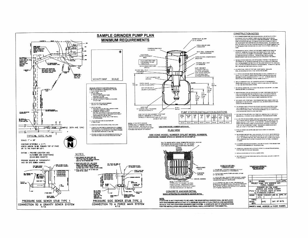
APPENDIX A LUD STANDARD PLANS FOR SEWER MAINS APPENDIX B LUD STANDARD PLANS FOR SIDE SEWERS APPENDIX C LOCAL JURISDICTION STANDARD PLANS (IF APPLICABLE) APPENDIX D WSDOT STANDARD PLANS (IF APPLICABLE) APPENDIX E STANDARD PLANS FOR PUMP STATIONS APPENDIX F STANDARD PLANS FOR GRINDER PUMP SYSTEMS
Lakehaven Utility District Sanitary Sewer Specifications (07/2002) SPEC-DC-1
LAKEHAVEN UTILITY DISTRICT
SANITARY SEWER SPECIFICATIONS STATEMENT OF DESIGN CRITERIA All sanitary sewer facilities shall be designed, at a minimum, in accordance with the most current version of the "Criteria for Sewage Works Design" (Orange Book) is sued by the Washington State Department of Ecology. Lakehaven Utility District's "Standard Notes for Sewer Construction" and "Gravity Sewer Facilities Plan Review Checklist," which follow this statement, and any future supplements to be issued by Lakehaven Utility District, shall govern when they are more restrictive and/or conservative than the Orange Book criteria.
Lakehaven Utility District Sanitary Sewer Specifications (07/2002) SPEC-DEF-1
LAKEHAVEN UTILITY DISTRICT
SANITARY SEWER SPECIFICATIONS DEFINITIONS The definitions listed below relate only to the Sanitary Sewer Specifications, Sections 1 through 17. 1. "AASHTO" - American Association of State Highway and Transportation Officials. Whenever
AASHTO is referred to in these Specifications without designation of year, the reference is to the most current or revised specification in effect at the time of receiving the Contract.
2. "ANSI" - American National Standards Institute (formerly United States of America Standards Institute). Whenever ANSI is referred to in these Specifications without designation of year, the reference is to the most current or revised specification in effect at the time of receiving the Contract.
3. "Appurtenances" (as in piping and appurtenances) – Materials required to successfully install and complete a piping system, including any miscellaneous items that are not identified separately. Appurtenances may include such items as pipe jointing materials (bolts, gaskets, glands, etc.), pipe restraints, wall mounting hardware for pipes within vaults, pipe locating tape and wire, and manhole ladders or other hardware inside manholes.
4. "ASTM" - American Society for Testing and Materials. Whenever ASTM is referred to in these Specifications without designation of year, the reference is to the most current or revised specification in effect at the time of receiving the Contract.
5. "AWWA" - Whenever AWWA is referred to in these Specifications without designation of year, the reference is to the most current or revised specification in effect at the time of receiving the Contract.
6. "As Directed," "As Permitted," "Approved," or words of similar import, mean the direction, requirements, permission, approval or acceptance of the Engineer, unless stated otherwise.
7. "Approved equal" OR "equal" - shall mean an item or material, which in the opinion of the General Manager of Lakehaven Utility District, is of equal quality to that item listed herein.
8. "As Shown," "As Indicated," "As Detailed," or words of similar import, refer to the Contract Drawings, unless stated otherwise.
9. Backfill – Refilling excavated areas with native or imported material.
10. "Bid" - A bid is the offer of a bidder, on a properly completed proposal form, to perform the Contract.
DEFINITIONS (Continued)
SPEC-DEF-2 Sanitary Sewer Specifications (07/2002) Lakehaven Utility District
11. "Buffer" – Zone contiguous with a sensitive area required to maintain function and structural stability of a sensitive area (open water body, wetland, or steep slope).
12. "Channel Migration Zone (CMZ) – The area where the active channel of a stream is prone to move and which represents a potential near-term loss of riparian habitat adjacent to the stream.
13. "Contract" - The Contract Documents as defined in the Conditions of Contract cover the performance of the work and the furnishing of all labor, equipment, materials and other property required for doing the work, and covering the performance of all other things required by said Contract Documents.
14. "Contract Drawings" - Drawings which have been prepared by or on behalf of the Owner, as a basis for bids, when duly made a part of this Contract by incorporation or reference. Drawings submitted in pursuance of the terms of the Contract by the successful bidder with his/her bid, and by the Contractor to the Owner, if and when approved by the Engineer. Drawings submitted by the Engineer to the Contractor during the progress of the work as provided for in the Contract.
15. "Contractor" - The person, partnership, corporation, association, or affiliation with whom the Owner has executed the Contract.
16. "District" - The word "District" shall mean Lakehaven Utility District, a municipal corporation of the State of Washington.
17. "Dry Season" (Western Washington) – May 16 to September 30 (or as defined by USFWS/NMFS).
18. "Emergency" – Sewer line failure (e.g., pipe break, pump station or lift station failure).
19. "Engineer" - The word "Engineer" used herein shall be understood to mean the General Manager of Lakehaven Utility District, or his/her duly authorized representatives acting directly or through his/her authorization. Engineer can occasionally refer to a private engineering firm, appointed by Lakehaven Utility District to have control of the work and carry out the intent of a project, or working on behalf of a developer under current developer extension agreement with Lakehaven Utility District. On any questions concerning the acceptability of material and construction, the decision of the General Manager of Lakehaven Utility District shall be final.
20. "Fold-and-Form Lining" – Method of repairing existing pipe by inserting a heated PVC or HDPE thermoplastic liner, folded or deformed into a U-shape, into an existing sewer main and rerounding the liner using heat and pressure.
21. "Heavy Rain Storm" – 0.5-inch of rain within a 24-hour period.
22. "Independent Testing Laboratory" - A private or public laboratory capable of testing work, soils
DEFINITIONS (Continued)
Lakehaven Utility District Sanitary Sewer Specifications (07/2002) SPEC-DEF-3
and materials, which is acceptable to Lakehaven Utility District.
23. "Inflow and Infiltration" – Water that enters a sewer system through indirect (infiltration) and direct (inflow) means. Infiltration is extraneous groundwater that enters the sewer system through leaking joints, crack, and breaks, or porous walls. Inflow is stormwater that enters the sewer system from storm drain connections (catch basins), roof leaders, foundation and basement drains, or through manhole covers.
24. "Inspector" - The engineering or technical inspector duly authorized or appointed by the General Manager of Lakehaven Utility District, limited to the particular duties entrusted to him.
25. "NMFS" – National Marine Fisheries Service.
26. "Owner" - Owner refers to Lakehaven Utility District or the entity contracting the work being completed.
27. "Pipe Backfill" – Material used to support pipes in trenches that can adequately transfer loads away from the pipe to the surrounding soils and prevent settlement; generally sandy, gravelly soil is used for pipe backfill, because it is one of the most compactable materials.
28. "Pipe Bursting" – Trenchless method of replacing an existing pipe by fragmenting the existing pipe and pushing it into the surrounding soil by pulling a bursting head or mandrel through the line. A new pipe (typically butt-fused HDPE) of equal or larger diameter is pulled behind the bursting head. New manholes are usually provided at the insertion and withdrawal pits.
29. "Project" - The undertaking to be performed as provided in the Contract documents.
30. "Property Owner" - shall mean the lawful and legal owner of a lot or parcel of land.
31. "Provide" - means "Furnish and Install."
32. "Quarry Spalls" – Angular mined rock.
33. "Right-of-Way" - Land, property or property interest, usually in a strip, acquired for or devoted to road and utilities purposes.
34. "Riparian Area" – Stream, lake or tidewater buffer.
35. "Sensitive Area" – Area requiring special consideration and protection (e.g., streams, wetlands, tidelands, steep slopes, erosion hazards, coal mine hazards).
DEFINITIONS (Continued)
SPEC-DEF-4 Sanitary Sewer Specifications (07/2002) Lakehaven Utility District
36. "Slip Lining" – Method of repairing existing pipe by inserting a new pipe of a smaller diameter into an existing host pipe. The new pipe is either continuous (typically butt-fused HDPE) or segmented (typically PVC, ductile iron, or HDPE).
37. "Soil Freezing" – Method of construction that minimizes dewatering and extra shoring requirements. Process involves drilling holes into the ground in a bowl shape around the area to be excavated, inserting self-contained tubes into the holes, and then circulating super-cooled fluid through the tubes in order to freeze the ground.
38. "Special Provisions" - Additions and revisions to the Standard and Supplemental Specifications that apply to an individual project.
39. "Specifications" - The word "Specifications" refers to the provisions in Sections 1 through 17 of this document and occasionally refers to manufacturer's specification of particular items or provisions and requirements for the prescribed work.
40. "Standard Plan" - refers to the current Lakehaven Utility District (LUD), Local Jurisdiction, and/or Washington State Department of Transportation (WSDOT) Standard Plans for the particular work being undertaken.
41. "State" - shall mean the State of Washington.
42. "Steep Slope" – Slope of 40 percent gradient or greater.
43. "Subcontractor" - A person, partnership, corporation, association or affiliation, other than the Contractor, supplying labor and materials, or labor only, at the site of the work.
44. "Trenchless Construction" – Methods of construction that require limited or no ground excavation. Examples of trenchless construction include slip lining, cured-in-place piping, fold-and-form lining, pipe bursting, microtunneling, and horizontal directional drilling.
45. "USFWS" – United States Fish and Wildlife Service.
46. "WDFW" – Washington State Department of Fish and Wildlife.
47. "Wet Season" (Western Washington) – October 1 to May 15 (or as defined by USFWS/NMFS).
48. "W.S.D.O.T." - refers to the Washington State Department of Transportation test methods and/or Standard Specifications for Road, Bridge and Municipal Construction. Whenever W.S.D.O.T. is referred to in these Specifications without designation of year, the reference is to the most current or revised specification in effect at the time of receiving the Contract.
49. "Work" - The provision of all labor, materials, equipment, and everything needed to successfully
DEFINITIONS (Continued)
Lakehaven Utility District Sanitary Sewer Specifications (07/2002) SPEC-DEF-5
complete a project, according to the Contract Specifications.
Lakehaven Utility District Sanitary Sewer Specifications (07/2002) SPEC-1-1
SECTION 1
CLEARING 1.1 GENERAL 1.1.1 This section includes provisions for the clearing and disposal of all objectionable material from the areas required for the construction of the work shown on the contract drawings or required by these specifications. 1.1.2 Unless otherwise noted on the Contract Drawings, the limits of clearing shall be determined by the Contractor and approved by the Engineer prior to beginning the work. Clearing shall be confined to the immediate vicinity of the construction, insofar as practicable, and shall not extend beyond the right-of-way, property, or easement lines shown on the contract drawings without the express written approval of the affected landowners. A copy of written approvals shall be transmitted to the Engineer at least seven (7) days prior to clearing. 1.1.3 Any portions of the project site where excavation is to be made or embankment is to be placed shall be cleared of all objectionable material such as brush, stumps and roots, grass and other vegetation, decayed vegetable matter, topsoil, rubbish, pavement and other materials that may interfere with proper prosecution of the work. Unless otherwise designated on the Contract Drawings, the Contractor shall not remove trees without authorization of the Engineer. The Contractor shall avoid serious injuries to trees that are designated not to be removed. If the Contractor seriously injures a tree, he/she shall repair the tree in accordance with the method approved by the Engineer. No major roots shall be cut, if, in the opinion of the Engineer, such cutting would seriously injure or imperil the safety of the tree. Trees to be removed shall be felled within the clearing limits. 1.1.4 Shrub and Tree Removal 1.1.4.1 General 1.1.4.1.1 Cut, remove and dispose of trees, stumps, and shrubs that occur in the areas required for construction. 1.1.4.1.2 Remove all stumps and matted roots in areas to be occupied by structures or pavements. 1.1.4.2 Remove trees, stumps, bushes, and shrubs to a depth of 12 inches below the elevation of the subgrade, finished earth surface or ground line.
SPEC-1-2 Sanitary Sewer Specifications (07/2002) Lakehaven Utility District
1.2 PAVEMENT REMOVAL 1.2.1 The sawing equipment and operation shall be in conformance with the latest edition of the Standard Specifications for Road, Bridge & Municipal Construction of the State of Washington, Department of Transportation, 1996 edition. Pavement to be removed shall be saw cut in neat, straight lines with vertical edges along the limits of pavement removal. Changes in width of repaving shall be made by cutting perpendicular and parallel to the centerline of the trench. The cut line for removal of pavement shall be reviewed by the Engineer in the field before cutting. Wheel cutting or jack hammering will not be considered an acceptable means of pavement "cutting," unless preapproved by the Engineer. However, even if preapproved as a "method of cutting" or if the Engineer directs the Contractor to utilize this "method of cutting," then no payment will be made for this type of work, but rather, it shall be considered incidental to the work. 1.2.2 All asphalt and concrete materials must be disposed of at an approved "solid waste" site in accordance with all federal, state, and county regulations. 1.3 LAWN REMOVAL 1.3.1 The existing turf shall be removed from lawn areas and shall be stored for use in resodding the area. The area of sod to be removed shall be laid out in squares or strips of such size as to provide easy handling and matching. The sod shall then be carefully cut along these lines to a depth of four (4) inches, taking care to keep all cuts straight and all strips the same width. After the sod has been cut vertically, it shall be removed to a uniform depth of approximately three (3) inches with an approved type of sod cutter. This operation shall be performed in such manner as to insure uniform thickness of sod throughout the operation. 1.3.2 The sod strips shall be rolled or piled and shall be maintained in a moist and viable condition until the area is resodded. Resodding shall be completed within ten (10) days after removal of the sod. 1.4 DISPOSAL OF CLEARED MATERIAL 1.4.1 It is the Contractor's responsibility to comply with all the requirements of all local, state and federal regulations governing disposal of cleared material and construction waste. 1.5 CONSTRUCTION WASTE DISPOSAL 1.5.1 All required waste sites shall be provided by the Contractor. The Contractor shall be responsible for obtaining any and all necessary permits and shall comply with applicable codes, laws, and standards for disposal. This includes appropriate SEPA compliance for temporary stockpiling and disposal of excavated material. Waste sites shall be operated in such a manner as to meet the safety and health requirements of the state, county, and local governmental authority. Sites, operations, or results of such operations, which create a definite nuisance problem, or which result in damage to public or private properties, will not be permitted.
Lakehaven Utility District Sanitary Sewer Specifications (07/2002) SPEC-1-3
1.5.2 Air, noise, and other types of pollution caused by the Contractor's use of such sites, shall be the responsibility of the Contractor. The Contractor agrees to save the Owner harmless from any damages, claims of damages, and fines imposed by local or state agencies, such as the State Pollution Control Board, arising from the Contractor's use and operation of any site. 1.5.3 All costs and expenses involved in securing, maintaining, and operating any waste site, including final cleanup and any erosion or anti-pollution controls required in any permits, property owner agreements, and grading regulations will be considered as incidental to the contract and such costs and expenses shall be included in the unit contract prices for the various pay items shown in the proposal.
Lakehaven Utility District Sanitary Sewer Specifications (07/2002) SPEC-2-1
SECTION 2
TEMPORARY EROSION AND SEDIMENTATION CONTROL 2.1 EXISTING DRAINAGE FACILITIES The Contractor shall be required to preserve existing ditches, culverts, drainage channels, etc., and to make every attempt to construct the Project with as little adverse impact as is practical on existing storm drainage facilities. Trench "spoils" or import material shall not be allowed to be stored in ditches or adjacent to ditches if the contractor's work efforts cause stockpiled materials to migrate into existing storm drainage facilities. Stockpiled materials shall neither impede nor prevent storm water run-off from entering ditches, swales, drainage channels, or culverts, nor shall stockpiled materials or equipment create ponding or entrapment of storm water in areas which presently do not experience ponding or entrapment of water. The Contractor shall immediately restore ditches and drainage facilities that are damaged, plugged, or blocked, provide temporary pumping if directed by the Engineer, protect and maintain all existing drainage facilities, and no separate monies will be due the Contractor for performing this item. Furthermore, no separate monies will be due the Contractor if special construction is required to include off-site storage of materials, conveyor systems, or any other special means are utilized to insure that existing storm drainage facilities are kept in service and their original integrities are kept intact. 2.2 MATTING, NETTING AND THE USE OF STRAW 2.2.1 This section includes provisions for the installation of temporary erosion control as shown on the Contract Drawings or may be necessary during construction of the sewer system. Place matting, netting or straw on the areas shown on the Contract Drawings or where slopes are 3:1 or steeper. 2.2.2 Material 2.2.2.1 Matting and netting for erosion control shall be as specified below. Other material manufactured especially for erosion control may be used when approved by the Engineer in writing. Matting shall not be dyed, bleached, or otherwise treated in a manner that will result in toxicity to vegetation. 2.2.2.1.1 Jute matting shall be a uniform open plan weave of single yarn. The yarn shall be loosely twisted and shall not vary in thickness by more than one half its normal diameter. The matting shall have an average weight or 1.22 pounds per linear yard, plus or minus five (5) percent. 2.2.2.1.2 Excelsior matting shall be wood excelsior, with a minimum thickness of 1/4 inch and an average weight of 1.07 pounds per linear yard, plus or minus five (5) percent. Excelsior matting shall be covered on one side with a woven fabric, consisting of twisted paper or cotton cord, having a minimum mesh size of 1 X 1 inch and a maximum size of 1-1/2 X 3 inches.
SPEC-2-2 Sanitary Sewer Specifications (07/2002) Lakehaven Utility District
2.2.2.1.3 Netting for erosion control of areas seeded and mulched or sodded shall be black polypropylene extruded oriented plastic net with approximate 1/2 X 1/2 inch rectangular openings and a nominal weight of five (5) pounds per 1,000 square feet. 2.2.2.1.4 Staples shall be of No. 11 gauge steel wire, not less than six (6) inches long. 2.2.2.2 Straw cover for erosion control shall be new or stable bedding straw, uniformly spread at the rate of two (2) tons per acre for new straw and three (3) tons per acre for stable bedding straw. 2.2.3 Installation 2.2.3.1 Place matting immediately after the earth surface has been prepared. Preserve the required line, grade, and cross section of the area treated. 2.2.3.2 Unroll matting in the direction of the flow of water and apply without stretching, so that it will lie smoothly, but loosely, on the surface. Bury the up-channel on top of the slope end of each piece of matting in a narrow trench, at least eight (8) inches deep, fill the trench and tamp firmly. Where one roll of matting ends and a second begins, bring the end of the upper roll over the buried end of the second roll, so that there will be a four (4) to six (6) inch overlap. 2.2.3.3 Construct check slots at each 50 feet, longitudinally in the matting, or as directed by the Engineer. The slots shall be narrow trenches, at least five (5) inches deep. Fold over the matting and bury to the full depth of the trench; then close the trench and tamp firmly. Where two (2) or more widths of matting are laid side by side, the overlap shall be at least four (4) inches. 2.2.3.4 Place staples across matting at ends, junctions and check slots, spaced approximately ten (10) inches apart. Place staples along the outer edges and down the center of each strip of matting, about three (3) feet apart. Place staples along all lapped edges, 24 to 36 inches apart. 2.2.3.5 Install excelsior matting with the fabric on top. 2.2.3.6 After installation, roll with an approved roller to assure contact with the soil. 2.2.3.7 For matting installed on cut or filled slopes, the Engineer may require adjustments in trenching or stapling to fit slope conditions. 2.2.3.8 Incorporate straw cover in the soil with a roller equipped with straight studs made of 7/8-inch steel plate, placed approximately eight (8) inches apart and staggered. The studs shall be not less than six (6) inches long, nor more than six (6) inches wide, and shall be rounded to prevent withdrawing the straw from the soil. The roller shall have sufficient weight to incorporate the straw into the soil, so that it will not support combustion and will leave a uniform surface.
Lakehaven Utility District Sanitary Sewer Specifications (07/2002) SPEC-2-3
2.2.3.9 Maintain erosion control material in good condition until all work on the project has been accepted. 2.3 SLOPE PROTECTION AND LAWN ESTABLISHMENT 2.3.1 General 2.3.1.1 This section describes the materials and methods to be used to protect slope areas and establish lawns through hydroseeding and/or sodding. 2.3.1.2 Submit a list of the items described in Section 2.2.2, including the quantities to be used and the manufacturer's name, for approval. In addition, provide duplicate copies of seed certification conforming to the Department of Agriculture and State of Washington requirements for grass seed. The certification shall include as a minimum: 1. Common name of seed or seeds if combination 2. Lot number(s) 3. Net weight 4. Percentage purity of seed type 5. Percentage germination of each seed type 6. Percent weed seed as defined by the State of Washington 2.3.2 Products 2.3.2.1 Water. The Contractor shall supply clear, clean, potable water, or approved reclaimed water, for hydroseeding and irrigating. 2.3.2.2 Fertilizer 2.3.2.2.1 Hydroseed. Use fertilizer consisting of five (5) percent nitrogen, 20 percent phosphoric acid, and 20 percent potash plus trace elements applied at a rate of 650 pounds per acre. In addition, use nitroform organic nitrogen consisting of 38 percent nitrogen, zero percent phosphoric acid, and zero percent potash applied at a rate of 220 pounds per acre. In addition, use Terra Tack III, applied at a rate of 40 pounds per acre. Terra Tack III shall be free flowing, pH 7 to 8, minus 20 mesh, granular powder made from seaweed extracts containing calcium and other polyvalent cations. 2.3.2.2.2 Sod Preparation Areas. Use fertilizer consisting of ten (10) percent nitrogen, 20 percent phosphoric acid, 20 percent potash plus trace elements. Apply at a rate of 30 pounds per 1,000 square feet to installed topsoil and work into soil to a depth of four (4) to six (6) inches. 2.3.2.3 Mulch. Use green-dyed mulch consisting of natural wood cellulose fiber, containing no germination or growth inhibitors. Supply in moisture-proof containers marked by the manufacturer to show the air dry content. Provide Conweb Hydro Mulch 2000 as manufactured by Conweb Corp.;
SPEC-2-4 Sanitary Sewer Specifications (07/2002) Lakehaven Utility District
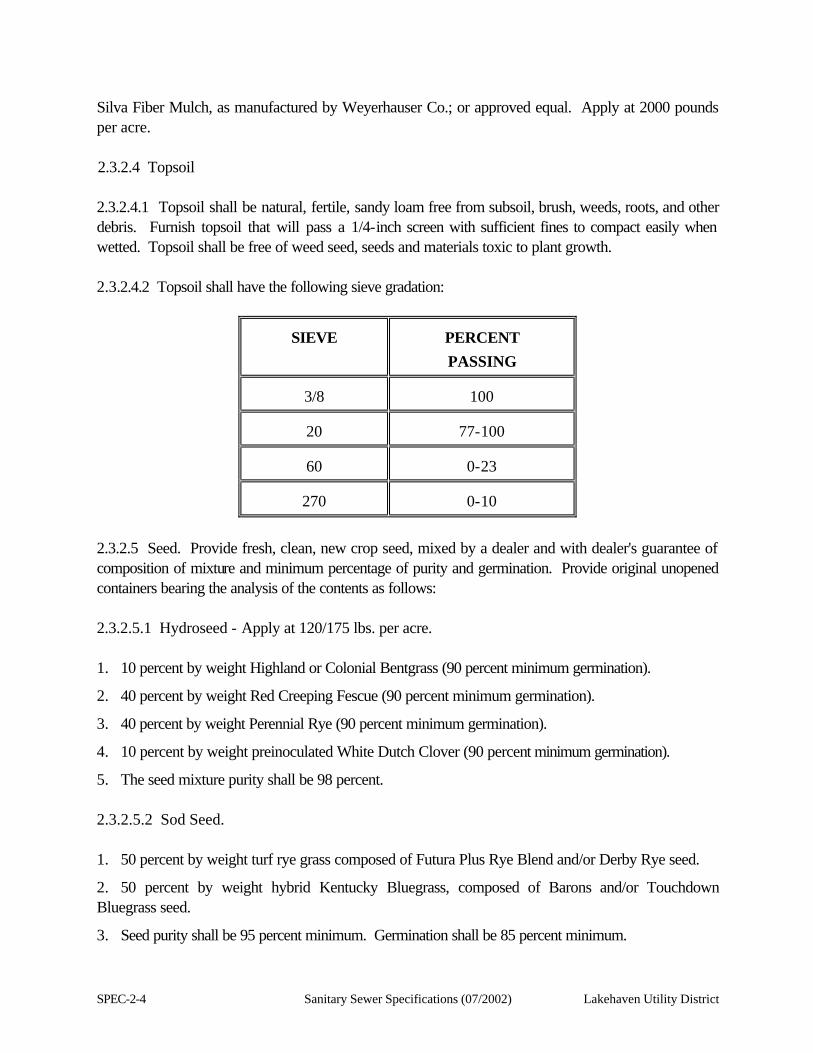
Silva Fiber Mulch, as manufactured by Weyerhauser Co.; or approved equal. Apply at 2000 pounds per acre. 2.3.2.4 Topsoil 2.3.2.4.1 Topsoil shall be natural, fertile, sandy loam free from subsoil, brush, weeds, roots, and other debris. Furnish topsoil that will pass a 1/4-inch screen with sufficient fines to compact easily when wetted. Topsoil shall be free of weed seed, seeds and materials toxic to plant growth. 2.3.2.4.2 Topsoil shall have the following sieve gradation:
SIEVE
PERCENT PASSING
3/8
100
20
77-100
60
0-23
270
0-10
2.3.2.5 Seed. Provide fresh, clean, new crop seed, mixed by a dealer and with dealer's guarantee of composition of mixture and minimum percentage of purity and germination. Provide original unopened containers bearing the analysis of the contents as follows: 2.3.2.5.1 Hydroseed - Apply at 120/175 lbs. per acre. 1. 10 percent by weight Highland or Colonial Bentgrass (90 percent minimum germination).
2. 40 percent by weight Red Creeping Fescue (90 percent minimum germination).
3. 40 percent by weight Perennial Rye (90 percent minimum germination).
4. 10 percent by weight preinoculated White Dutch Clover (90 percent minimum germination).
5. The seed mixture purity shall be 98 percent. 2.3.2.5.2 Sod Seed. 1. 50 percent by weight turf rye grass composed of Futura Plus Rye Blend and/or Derby Rye seed.
2. 50 percent by weight hybrid Kentucky Bluegrass, composed of Barons and/or Touchdown Bluegrass seed.
3. Seed purity shall be 95 percent minimum. Germination shall be 85 percent minimum.
Lakehaven Utility District Sanitary Sewer Specifications (07/2002) SPEC-2-5
2.3.2.6 Erosion Mat. Provide a matting or netting erosion mat as described in Section 2.1 of these Specifications. 2.3.2.7 Sod. Sod shall be first quality turf grass sod composed of acceptable grass mixtures, as described in Section 2.3.2.5 of these Specifications. Sod shall be removed from the nursery and be stripped to a uniform soil thickness between 3/4 to 1 inch. Prior to stripping, sod shall be mowed to 1-1/2 to 2 inch height. Sod may be cut and rolled or may be cut in "planks" for installation, as is the suppliers standard; however allowable deviation from width and length supplied shall not exceed two (2) percent. Broken rolls or torn and uneven planks or ends will not be acceptable. Sod shall have sufficient strength to support its own weight when supported from a firm grasp on ten (10) percent of the section. Sod shall be harvested, delivered and installed within a 48-hour period. Provide certification of delivery time. 2.3.3 Execution 2.3.3.1 General. Hydroseed all areas disturbed by the construction and not paved or landscaped. Areas to be hydroseeded include new cuts and embankments and shoulder areas not otherwise treated. To limit potential erosion damage, it is recommended that all slopes be hydroseeded, or otherwise protected, as soon as practical. 2.3.3.2 Topsoil Placement. Spread topsoil to a depth of not less than four (4) inches. After spreading, drag the area with a heavy plank float to produce a smooth, even surface. On slopes which are too steep to drag a float, hydroseed immediately following spreading topsoil and installation of erosion mat. Place topsoil as shown on the contract drawings. 2.3.3.3 Erosion Control. Install erosion matting and/or netting in accordance with Section 2.2.3 of these Specifications. 2.3.3.4 Hydroseeding. Fill hydroseeder tank with water and start agitator. Add mulch fiber material in accordance with machine capacity. Slowly pour Terra Tack III into tank in an amount to give an application rate of 40 pounds per acre. Then add fertilizers and seed in the required amounts. Apply or spray on the prepared area, thoroughly saturating the soil. 2.3.3.5 Sodding. Spread topsoil to a depth of not less than four (4) inches. Uniformly incorporate Sod Preparation Fertilizer into topsoil. Relevel, fine drag and rake with a heavy drag plank and float. Firmly roll with a lightweight roller. Thoroughly moisten and then scarify upper 1/2-inch prior to placing sod. Lay sod with staggered seams and butted joints. Do not stretch turf. Roll sod after firmly placed with lightweight water-filled roller. Begin irrigation within 30 minutes after placement and rolling. Irrigate to full depth of topsoil. Finished sod area shall match initial grade and contour. 2.3.3.6 Maintenance. Water areas and perform remedial work to establish a good, uniform stand of grass. Maintain for not less than 120 days or until the grass is established.
SPEC-2-6 Sanitary Sewer Specifications (07/2002) Lakehaven Utility District
2.4 SILT FENCING 2.4.1 Silt fence shall be constructed of 2" X 2" 14 gauge welded wire fabric and Mirafi 140 Bidim filter fabric material as shown on the plans or District approved equal. 2.4.2 The silt fence shall be constructed to control erosion on newly graded or unprotected slopes and berms, as shown on the Contract Drawings or as directed by the Engineer. The fence shall provide temporary protection and shall be removed once hydroseeded vegetation has developed to control erosion. The fence shall be erected and removed only in those locations specifically designated by the Engineer or as shown on the Contract Drawings. 2.4.3 All costs associated with furnishing, installing, maintaining, removing, and any other item of work necessary for controlling erosion, shall be considered incidental to the project, and as such, merged in the various lump sum and unit prices bid. 2.5 WORK IN AND NEAR WETLANDS, STREAMS AND TIDELANDS With the listing of several Ecological Significant Units (ESUs) of chinook, chum, and sockeye salmon, bull trout, and steelhead trout in Washington state as "threatened" or "endangered" species under the federal Endangered Species Act (ESA), and the proposed listing of several other salmonid species, work necessary to construct sewer facilities in and adjacent to aquatic habitat where listed species occur could conflict with conditions imposed by the ESA. To avoid risks associated with the "take" of a "threatened" or "endangered" species, and in order to promote their conservation and protection, the following Best Management Practices (BMPs) have been developed. These BMPs are specifically designed to avoid or reduce impacts to aquatic habitat that might otherwise occur in the construction of sewer facilities. Although based on the best available science and practice, these BMPs are unlikely to remain static or unchanging. This is in recognition of the fact that new developments in science, law, and/or regulation are expected to result in new and improved standards of environmental protection. New information and/or improved environmental protection practices will be monitored and, where appropriate, will be adopted to supplement or supersede the current BMPs. All costs associated with compliance with the BMPs shall be considered incidental to the project, and as such, merged in the various lump sum and unit prices bid. 2.5.1 Construction Protocols All necessary local, state, and federal permits must be obtained prior to initiating non-emergency work. Work in and near wetlands, streams and tidelands must conform to local Sensitive/Critical Areas Ordinances. Work in and near streams or other surface water features will require a Hydraulics Project Approval (HPA) Permit from the Washington Department of Fish and Wildlife (WDFW). Discharge of soils, pipes, or other material into wetlands, streams or tidelands will require a 404 Permit (Clean Water Act) issued by the U.S. Army Corps of Engineers (ACOE), and may require a 401 Water Quality

Lakehaven Utility District Sanitary Sewer Specifications (07/2002) SPEC-2-7
Certification (Clean Water Act) and Coastal Zone Management Program Consistency Response from the Washington State Department of Ecology (DOE). Any work within a shoreline of the state will need to conform with the requirements of the Shoreline Management Program, and work within (or under) navigable waters will require review under Section 10 of the River and Harbors Act. 2.5.2 Erosion and Sediment Control (ESC) Measures 2.5.2.1 General The most important aspect of protecting aquatic habitat during construction is the control of sediment discharge into the aquatic systems and protection of riparian vegetation. Erosion control measures shall be designed in accordance with the most current DOE Stormwater Management Manual for the Puget Sound Basin or other relevant state or local regulations and design standards (i.e., King County Storm Water Design Manual; Washington Hydraulic Code). The ESC plan shall include a description of training that will be provided to all construction personnel. The training will establish the importance and mechanics of the ESC elements of the project. Appropriate ESC facilities shall be installed and maintained in effective operating condition throughout construction. The extent of required ESC measures will depend on the extent of earthwork, soil types, topography, season, weather conditions, and resulting erosion potential. Back up equipment and ESC supplies shall be available or stockpiled for emergency situations. During periods of heavy rain storms (defined as greater than 0.5-inch of rain in a 24-hour period), continuation of construction work shall be evaluated and ESC monitoring efforts shall be increased. Work involving soil movement (i.e., grading) shall be discontinued. Equipment and personnel shall be available to construct and maintain all necessary erosion control facilities. All construction debris shall be properly disposed of to avoid discharge of material into a waterway or wetland or cause any water quality degradation. All excess material shall be disposed of at an approved disposal site. 2.5.2.2 Perimeter Protection Clearing limits shall be flagged before any land disturbing activities begin. Limit cleared work areas to the area required to conduct the construction activities. Laydown areas for equipment, piping, and appurtenance storage shall be located outside of wetland and riparian areas. For purposes of these specifications, wetland and riparian areas shall be defined per the method/description assigned by the respective federal, state, or local government agency that has jurisdiction over the proposed construction activity. Should the project involve a federal, as well as a state/local permitting component, the federal definition shall control.

SPEC-2-8 Sanitary Sewer Specifications (07/2002) Lakehaven Utility District
Prior to construction, all wet areas within the construction zones shall be isolated by filter fabric fencing or equivalent or better methods. Filter fabric perimeter fencing shall be installed per DOE’s Manual specifications and these plans and specifications, downslope of any disturbed areas where potential for sheetflow or channelized flow of water exists. Work on guttered roadways shall be preceded by identification of gutter outlets and appropriate screening or blockage of storm drains as needed to prevent turbid runoff discharge to streams. Silt fabric shall be one piece or continuously sewn to make one piece for the full height of the fence fabric. Disturbance of native soils and vegetation shall be minimized during silt fence installation. At a minimum, posts shall be placed at least every 6 feet and be driven into the ground to a depth of at least 1-foot. Side casting soils on the downhill side of the fence shall not be allowed. Filter fabric shall be toed in using washed gravel. The condition of the filter fabric fence shall be monitored to keep the fence in good condition, and the downhill side of the filter fabric shall also be inspected to ensure the silt fencing is preventing silts from entering downslope areas. Sediment shall be removed when the sediment is a maximum of 6 inches deep and disposed of at an appropriate site. Any damaged section of silt fence shall be repaired immediately. The uphill side of the fence shall be monitored for any signs of the fence clogging and channelization of flows parallel to the fence. If this occurs, replace the fence and/or remove the trapped sediment. Filter fabric that has deteriorated due to ultraviolet radiation shall be replaced. 2.5.2.3 Cover Requirements During the dry season, cleared and excavated soils or imported soils needed for backfill or site restoration shall not be stored within at least 50 feet of the ordinary high water mark of streams, lakes, or other watercourses (dry or flowing); and shall not be deposited or stored where materials can be eroded by high water or storm runoff. Soil stockpiles stored within 50 to 100 feet of water bodies shall be covered with waterproof material, if left exposed for longer than 12 hours. During the wet season, cleared and excavated soils or imported soils needed for backfill or site restoration shall not be stored within at least 150 feet of the ordinary high water mark. If feasible, these soils should be stored outside of the 100-year floodplain or channel migration zone. The practicality of storing soils outside of these zones will depend on the extent of these zones and the duration of the proposed work. If excavated or imported soils need to be stored for less than 7 days or transporting these soils into and out of the area could cause additional harm to the local area (i.e., wider temporary construction road or increased compaction of the area), then soils may be temporarily stored within the 100-year floodplain or channel migration zone, provided alternative stockpile locations outside of these zones are identified prior to commencement of the excavation activities. If conditions develop that may result in extreme high waters in the work areas, the work area shall immediately be secured and the stockpiled soils moved to the alternative location as necessary.
Lakehaven Utility District Sanitary Sewer Specifications (07/2002) SPEC-2-9
Temporary soil stockpiles shall be covered with waterproof material when stockpile areas are located near streams or wetlands and are left exposed for longer than 12 hours. Stockpiled material shall be covered during rainstorms, if the runoff resulting from the storm could transport material into a stream or wetland area. Temporary cover measures shall be installed to protect all disturbed areas that will remain unworked for more than 7 days during the dry season (Western Washington - May 16 to September 30 / or as defined by USFWS/NMFS construction season schedule) or for more than 2 days during the wet season (Western Washington - October 1 to May 15 / or as defined by USFWS/NMFS). Any area to remain unworked for more than 30 days shall be seeded or sodded. ESC measures should be maintained until vegetation has been reestablished. Mulch may be used as cover on disturbed areas that require cover measures for less than 30 days. All areas, including stockpiles, with slopes of 3H:1V or steeper and with more than 10 feet of vertical relief shall be covered if they are to remain unworked for more than 12 hours during the wet season. Accepted cover methods include, but are not limited to, mulch, erosion control nets and blankets, visqueen sheeting, hydroseeding and mulching, and sodding. Material necessary to cover all disturbed areas shall be stockpiled on-site during the wet season. When spreading straw mulch, the straw should not be cut or broken into short stalks. The minimum depth of straw mulch shall be 2 inches. Mulch shall be loose enough to permit penetration of sunlight and air circulation but dense enough to shade the ground, reduce evapotranspiration, and prevent or materially reduce erosion of the underlying soil, including elimination of raindrop impacts. Foot stomping or other means to compact straw may be necessary in areas exposed to wind. Erosion control nets and blankets shall be used to prevent erosion and hold seed and mulch in place on steep slopes and in channels to allow vegetation to become well established. Nets and blankets may also be used to stabilize 2H:1V or steeper slopes with more than 10 feet of vertical relief. If erosion control nets or blankets are used, the nets and blankets shall make good contact with the ground, so no erosion occurs beneath the net or blanket. Any areas of the net or blanket that are damaged or not in close contact with the ground shall be repaired and stapled immediately. Visqueen/plastic sheeting shall have a minimum thickness of 0.06 mm. Quarry spalls or other suitable protection (i.e,, washed rock, coir or straw logs, or continuous berm) shall be installed at the toe of the slope to reduce or prevent erosion velocities in the runoff. Torn sheets shall be repaired or replaced immediately. Plastic covering shall be installed and maintained tightly in place by using sandbags, tires on ropes with a maximum 10 foot grid spacing in all directions, or other comparable methods to ensure even contact with the ground. All seams shall be taped or weighted down full length with at least a 12-inch overlap of all seams. Plastic covering sheets shall be toed in at the top of slopes in order to prevent surface water flow beneath the sheets. If plastic begins to deteriorate due to ultraviolet radiation,
SPEC-2-10 Sanitary Sewer Specifications (07/2002) Lakehaven Utility District
remove and replace it immediately. Plastic shall be removed when it is no longer needed. Clean runoff from visqueen sheeting may be directly discharged to maximize capacity of on-site systems to manage turbid water. 2.5.2.4 Run-on Control Measures Runoff from undisturbed areas shall be diverted from areas of construction activity by utilizing existing road drainage ditches and drainage ways as much as possible. Where this is not possible, diversion dikes and swales shall be constructed, as practicable, so runoff from undisturbed areas will not be contaminated by construction activity. In locations where off-site flow must cross disturbed areas, temporary culvert pipe shall be installed, as required, to convey the water across the disturbed areas to the natural flow path. 2.5.2.5 On-site Conveyance Control/Runoff Control and Treatment Measures Sediment shall be trapped on-site using filter fabric fences, straw bales, sediment traps, temporary pressurized filtration systems, or other appropriate methods. Stormwater runoff from disturbed areas within the limits of construction and from staging and laydown areas shall be collected and treated before release. Runoff, stormwater, and wastewater flows shall be controlled and treated during construction to minimize water quality impacts. All runoff must meet the most recent state standards (current minimum standards set in Chapter 173-201A WAC). Ponds, pressure filtration or other suspended solids removal systems, biofiltration via sheetflow dispersion across flat vegetated (grassy) areas, or other approved measures shall be used to treat and dispose of stormwater runoff, dewatering, and process wastewater. Said runoff, effluent, or wastewater shall meet required local or regional water quality standards prior to release from the site. Any release ultimately discharging into streams or other open water systems shall be clean water and shall not affect water temperature, pH, or dissolved oxygen and shall be released at rates that do not appreciably alter volume or flow velocities. Water with pollutants will require other disposal methods in accordance with local, state, and federal laws. A vactor truck shall be available during construction in or near all wet areas to assist in the removal of mud and silty water when appropriate (i.e., adequately sized treatment ponds cannot be constructed to control stormwater if shallow groundwater is encountered). All entrances and parking areas used by construction traffic shall be stabilized to minimize erosion and tracking of sediment off-site. A separation geotextile shall be placed under the rock material to prevent fine sediment from pumping up into the rock pad. Catch basin protection shall be installed at storm drain inlets down-slope and within 500 feet of any disturbed area or construction entrance. Filter fabric shall only be used as a catch basin protection if it is installed over the grate and ponded runoff will not be a traffic or erosion hazard. Filter fabric shall not be placed under the grates of any catch basin. Accumulated sediment on or around the filter fabric
Lakehaven Utility District Sanitary Sewer Specifications (07/2002) SPEC-2-11
protection shall be removed immediately. Any sediment in catch basin inserts shall be removed when the sediment has filled one-third of the available storage. The filter media for the insert shall be cleaned and replaced at least monthly or more frequently depending on specific site issues. Straw bales used for barriers shall be standard size, with an approximate weight of 70 pounds, tied with twine or wire, and free of noxious weeds or other weedy plant species. Bales shall be installed so that the bindings are oriented around the sides rather than along the top and bottom of the bale, in order to prevent deterioration of the bindings. Bales shall be installed with the ends of adjacent bales tightly abutting one another. Bales shall be entrenched and backfilled with the ends of adjacent bales tightly abutting one another. A trench shall be excavated the width of the bale and the length of the proposed barrier to a minimum depth of 4 inches. The trench shall be deep enough to remove all grass and other material that might allow flow to pass under the bale without treatment. Each bale shall be securely anchored by at least two stakes driven through the bale. The first stake shall be driven toward the previously laid bale to force the bales together. Any gaps between bales shall be chinked with straw to prevent untreated water from escaping between the bales. When bales are placed across channels, the bales shall extend to such length that the bottom of the end bales are higher in elevation than the top of the lowest middle bale to ensure water flows through or over the barrier rather than around the barrier. Sediment shall be removed from basins, catch basins, check dams, and traps when capacity has been reduced by 50% or when more than 1 foot of sediment has accumulated. 2.5.2.6 Dewatering – Groundwater Control Excavations in areas of high groundwater requires control of the groundwater in the construction area in order to effectively and safely excavate open trenches and avoid and minimize impacts to aquatic habitats. The local groundwater table can be temporarily suppressed in the immediate construction area by using well points or deep well systems to keep water out of the excavation areas. Sump pumps can also be used to remove water in the excavated areas. Water removed by well points or deep well systems is typically clear and non-turbid while water removed directly from an excavated area with sump pumps is generally turbid. Alternative technologies, such as ground freezing, should also be considered, especially when more conventional methods may not provide the level of control required. Trench excavations shall be dewatered by using well point, deep well systems, sumps with pumps, or other approved methods (i.e., ground freezing). Dewatering systems shall be sufficient to lower the water level in advance of the excavation and/or maintain it continuously to keep the trench bottom and sides firm and dry.
SPEC-2-12 Sanitary Sewer Specifications (07/2002) Lakehaven Utility District
Dewatering systems shall be designed and operated so as to prevent removal of the natural soils. The quantity and quality of discharge water from the groundwater control and dewatering system shall be in conformance with all federal, state, and local regulations. Well points and deep wells may be placed in intervals along the construction area as necessary to depress the local groundwater table during construction. These wells may be pumped at relatively high rates and may be used to lower the groundwater level within the vicinity of the excavation to minimize water seepage into the trench or work area. Monitor wells installed within the vicinity of the excavation can be used to monitor the effectiveness of the pumping wells. In general, discharge water resulting from the use of deep wells and well points is not turbid once the well has been established and can normally be discharged directly onto an adjacent vegetated area, if ground infiltration characteristics are adequate to handle the discharge over the period of pumping. Adequate detention shall be provided if soil infiltration is not adequate to handle the pumped water. Discharge resulting from the initial cleaning of the wells or well points shall be routed to a sediment removal facility or directed to a detention pond or stormwater system. Dewatering shall be terminated as soon as practical. In the event dewatering is for (1) a prolonged duration (i.e., more than 48 hours), and/or (2) requires pumping substantial volumes of water (i.e., greater than 250 gpm); and (3) involves withdrawals from shallow aquifer systems in hydraulic connection with nearby surface water streams supporting listed species and/or critical habitat supporting one or more life stages (e.g., spawning/rearing habitat), the effects of such dewatering on said streamflows, habitat, and water quality conditions shall be monitored during the course of the dewatering process. Quality of dewatering discharge must meet minimum state standards (current standards set in Chapter 173-201A WAC). Dewatering discharge shall be released at appropriate volumes and velocities to avoid significant changes in water surface elevation and velocities of adjacent water bodies. Should potential adverse impacts (i.e., increased water temperatures, changes in pH, dissolved oxygen or water clarity, increased velocities) upon listed species be determined, the dewatering activity shall be suspended until suitable instream conditions can be restored and properly maintained. Discharges of turbid water pumped into detention ponds or sediment removal facilities shall, if practical, be directed to existing stormwater collection systems, if approved and permitted in writing by the local jurisdiction. In all other circumstances, stored, turbid water shall not be discharged to surface water streams, if reintroduction of said water would increase existing temperature or turbidity conditions.
Lakehaven Utility District Sanitary Sewer Specifications (07/2002) SPEC-2-13
If well points are used, they shall be adequately spaced to provide the necessary dewatering and shall be sand packed or otherwise established to prevent pumping of fine sands or silts from the subsurface. A continual check shall be maintained to ensure subsurface soils are not being removed by the dewatering operation. In tight soil areas, where the rate of groundwater infiltration is slow, pumping directly from the trench may be feasible. However, discharge water associated with the use of these pumps is generally turbid and shall require treatment prior to release to a storm drain, waterway, or wetland. Open or cased sumps shall not be used as a primary dewatering method for excavations that are deeper than 2 feet below the natural water table. If water has caused the bottom of the trench to become unacceptable for placing and compacting bedding material, then crushed rock or quarry spalls shall be placed in the bottom of trenches immediately after excavation to improve the bearing capacity of the soil and reduce sediment in the pumped water. If possible, a depression in the down gradient portion of the trench shall be excavated to collect water for removal. Water shall be filtered using an approved method or allowed to settle in a sediment trap or pond in order to remove sand and fine-sized soil particles before disposal into any drainage system which conveys water to a stream, wetland, or pond. Said facilities shall be designed to meet regulatory requirements (WAC 173-201 A). . Sedimentation ponds or biofiltration swales shall not be located within wetlands or stream buffers. Adequate standby pumping equipment shall be maintained on the job site at all times to insure efficient dewatering and maintenance of dewatering operation for all ordinary emergencies, including power outages. The equipment shall be operated prior to complete shutdown in a manner that will allow the groundwater level to rise gradually to its static level. The construction and abandonment of all wells used in dewatering systems shall comply with DOE requirements (Chapter 173-160 WAC and Chapter 18.104 RCW). 2.5.3 Streams and Riparian Areas Construction within streams and riparian areas should be conducted with extreme caution to avoid the introduction of material/sediment into the waterways regardless of whether listed fish species have or have not been documented in the stream. Disturbance in waterways that eventually discharge into a system that supports listed fish can be considered by the NMFS/USFWS to have the potential to adversely affect listed species or their critical habitat.
SPEC-2-14 Sanitary Sewer Specifications (07/2002) Lakehaven Utility District
2.5.3.1 Stream and Riparian Measures Construction of non-emergency repairs shall be limited to periods of low flow or other periods identified by fisheries agencies, as approved by NMFS/USFWS, to avoid disturbances to critical fish life stages per agency requirements. Construction within stream buffers shall cease during periods of heavy rain. Equipment shall be stored and refueled outside of streams and associated buffers and riparian zones, as feasible. Required setbacks shall be marked in the field prior to initiating any on-site work. Avoid instream work whenever feasible. Determine the feasibility of using a trenchless construction method (i.e., micro-tunnel bore and jack, horizontal directional drilling, slip lining, or pipe bursting) to install a pipe across a stream, before using open cut construction methods to install the pipe. Where work within the stream is necessary (i.e., soil conditions will not allow trenchless construction, physical location or pipe diameter will not allow slip lining or pipe bursting), flow shall be diverted to deflect as much of the stream energy as possible from cut banks and the channel bed. Flow diversion shall commence before trenching through streams or ditches, such that flow of the waterway remains continuous at all times and meets fish passage requirements per WDFW – HPA standards. Diversion of surface flows, where required, may include the use of culverts, sandbag cofferdams, and pumps. If pumps are used to divert water around the construction area, they shall be adequately screened to protect fish and debris from pump suction. When in-stream work is required, a construction window shall be selected, per NMFS/USFWS guidelines, when listed species are not present, if feasible. Remove fish from the construction reach before dewatering for any in-stream construction. A collection permit from WDFW and approval from NMFS and USFWS may be required to relocate fish from the work site. Electrofishing should be used as the final alternative for removing fish from a construction area. Seining, dipnetting, block netting, etc., may be sufficient and should be employed prior to electrofishing. Should electrofishing be appropriate, it shall be performed by qualified and experienced personnel, and shall be in accordance with Washington Department of Fish and Wildlife protocol (Appendix A, Attachment 1) and all other applicable state/federal laws, regulations, and guidelines. Absorbency booms shall be placed along the ordinary high water mark of streams, ponds, or lakes prior to initiating any on-site work as a precaution against spills. Construction access roads shall not be established across streams, unless a temporary stream crossing is the only access route to the adjacent construction area. If a temporary access road is required, it shall be constructed in such a manner to avoid any instream work or placement of structures (i.e., span stream with rail car or sheet piling supported at outside of the channel to act as a temporary bridge). Buried pipe shall be placed at least 4 feet deeper than the maximum anticipated depth of scour observed at the deepest portion of the channel throughout the potential meander width of the waterway.
Lakehaven Utility District Sanitary Sewer Specifications (07/2002) SPEC-2-15
Potential effects relating to anticipated depth and extent of possible scour shall be identified and mitigated pursuant to plans prepared by qualified hydrologists and/or fluvial geomorphologists. Topsoil from the stream buffer shall be stripped and stockpiled separately for subsequent replacement during restoration. Stream buffer topsoil shall also be stockpiled and covered separately from the adjacent upland soils. Areas where topsoil is stripped and replaced following construction shall be re-vegetated with species representative of adjacent functional riparian areas or better. Removal of woody plant species and/or whole trees within the stream buffer, that could provide shade or large woody debris to the stream, shall be avoided where feasible. If tree removal is necessary to gain access to facilities and undertake the project, 10-inch and larger diameter trees cleared from the stream buffer shall be retained. Said trees shall be cut into lengths of at least 12 feet and/or segments at least as long as channel width, whichever is greatest, and retained for placement as woody debris after construction is completed. Consult with Service Restoration Program or stream restoration consultants for effective woody debris placement methodology. 2.5.4 Wetlands In addition to the dewatering measures detailed in Section 2.5.2.6, measures to limit or avoid impacts to wetlands during construction are required to avoid potential impacts to surface water areas that support listed species or discharge to water supporting listed species and to meet selective permit requirements (i.e., Nationwide Permit 12). 2.5.4.1 Wetland Measures Construction of non-emergency repairs shall be limited to the dry season. The construction corridor width shall be reduced to 40 feet or less, wherever feasible. Locate equipment and material storage areas outside of wetlands and wetland buffers. Wetland topsoil and subsoil shall be stripped and stockpiled separately during construction for subsequent replacement during restoration. Stripped wetland topsoil shall also be stockpiled and covered separately from the adjacent upland soils. Where possible, 10-inch and larger diameter trees from the construction areas within wetlands and wetland buffers shall be retained, limbed and cut into lengths of at least 12 feet for placement as woody debris after construction is completed. Leave downed large wood and large stumps found in the wetland or wetland buffer in good condition, where possible. Where removal is required, maintain in good condition at maximum lengths feasible, if whole logs can not be relocated, and stockpile for subsequent restoration.
SPEC-2-16 Sanitary Sewer Specifications (07/2002) Lakehaven Utility District
Temporary access roads shall only be constructed as needed. No permanent access roads shall be constructed within wetlands or wetland buffers. When required, temporary access roads should be constructed in such manner that water from the road prism is not directly diverted to an adjacent wetland or stream. Appropriate material shall be used to construct temporary access roads. Wood chips or crushed rock on fabric mats shall be placed where soils are not saturated or highly organic. Steel mats or log rafts shall be used in areas of high organic soils (i.e., peat) or areas of saturated soils. Seepage barriers consisting of concrete collars, clay dams, or other impermeable materials shall be placed around pipelines, as necessary (i.e., on slopes), to maintain local hydrology patterns. If water could accumulate behind the dam, convey the water to a natural drainage area via pipes. Said barriers and drainage conveyance shall be installed at the time of trench backfill. A layer of impermeable material such as clay or bentonite (12 inches minimum) shall be placed at the depth of any impermeable layer punctured during excavation to prevent water in the wetland area from escaping into more permeable soil zones below the impermeable zone. Only suitable native soils or material supplied from an approved source, such as a sand and gravel operation, shall be used for backfilling in wetland habitats. Unsuitable native soil shall be disposed of at an approved off-site location. 2.5.5 Lakes and Tideland Measures Pipes may also be found in lakes, typically near the shoreline or within tidelands. These pipes may have been installed in order to allow adjacent development to be served by a gravity system, and may be located beneath the bottom of the lake or tideland or laid above ground within the water. If relocating the facility is not feasible, or would cause greater environmental damage than the repair or replacement of the existing facility, then the following measures should be applied, where feasible. Applicable riparian, wetland, and wetland buffer measures should also be applied when working in lake and tideland areas. • Sliplining – Involves the insertion of a smaller pipe into the existing pipe. • Cured-In-Place Piping – Involves inverting a cloth-like pipe impregnated with polyurethane resin
into the existing pipe, using hydrostatic head or air pressure (pipe accessed via existing manholes). The resin soaked material is then cured using heat to form a “sleeve” inside the existing pipe.
• Fold-and-Form Lining – Involves inserting a heated PVC or HDPE thermoplastic liner, folded or
deformed into a U-shape, into the existing sewer and rerounding the liner using heat and pressure.
Lakehaven Utility District Sanitary Sewer Specifications (07/2002) SPEC-2-17
• Pipe bursting – Replace the existing pipe with new pipe by dragging new pipe through the existing pipe, after it has been burst with an appropriately sized mandrel. This method may be viable only if the pipe is sufficiently buried beneath the bottom of the lake or shoreline.
• Replacement - Construct replacement line on shore and then lower the newly constructed pipe
section into the water parallel to old pipe segment. All joints of the replacement line would need to be restrained or fused to prevent separation of the new facility during installation or operation. (This would likely have limited application, since the length of pipe that could be lifted into position would be limited.)
Options to repair or replace pipes located in or under lakes or coastal waters may be limited by engineering constraints on the system. For pipes installed on a lake bottom or seabed, many of the above techniques would require divers to implement the repair activities to avoid dewatering of the work area. However, in situations where temporary dewatering of a work area is necessary, installation of cofferdams and dewatering within the cofferdams would be required. Fish should be “herded” or collected from the work area under the appropriate approval and/or collection permits required by WDFW, NMFS, and/or USFWS. The pumps within the cofferdams should be adequately screened to protect fish from pump suction. Any repair or maintenance requiring temporary dewatering should be conducted within the appropriate time period, to avoid sensitive salmonid species life stages as determined in consultation with WDFW, NMFS, and/or USFWS. 2.5.6 Steep Slopes Construction on steep slopes adjacent to streams and wetlands presents an increased probability that sediment can be delivered to these aquatic systems. Therefore, there is an increased sensitivity to construction in steep slope areas due to the potential increased risk to listed species. In general, avoid construction on steep slopes, unless the alternative will cause greater damage to public resources or is not feasible. 2.5.6.1 Steep Slope Measures Diversion bars or berms shall be used to divert surface water from steep slopes in the construction area. Straw bales or silt fences shall be placed to reduce runoff velocity in conjunction with collection, transport, and disposal of surface runoff generated in the construction zone. The amount of area that is cleared and graded at one time on steep slopes shall be limited to the immediate area of construction. Construction activities shall begin immediately after a section has been cleared and stripped of vegetation and restoration shall begin as soon as possible. Silt fence shall be erected down-slope of all disturbed areas prior to any up-slope grading. Silt fence shall not be installed on any slope steeper than 2H:1V.
SPEC-2-18 Sanitary Sewer Specifications (07/2002) Lakehaven Utility District
Steep slopes susceptible to sloughing during construction shall be stabilized, where needed, by use of subdrains and pipe collars designed to impair the seepage path of groundwater flow. Quarry spalls shall be placed in any ditch with a longitudinal slope greater than 5 percent. Quarry spalls shall be placed with sufficient overlap to provide interlocking and complete coverage of the ditch section to the satisfaction of the Engineer. Quarry spalls may be placed in ditches to serve as a check dam. 2.5.7 Accidental Spill Response A plan to prevent and contain accidental spills shall be prepared for all construction projects. A spill response plan shall comply with applicable federal, state, county, and city laws. Construction shall cease, if necessary, to prevent interference with immediate spill cleanup. If a spill were to occur, dewatering shall cease if it was creating flow that would mobilize the spill. Dewatering would not continue until the contained spill was cleaned up. A combination of filtration, biofiltration, or sanitary sewer discharge treatment may effectively treat routine small leaks from equipment through allowance for filtration, biodegradation, and volatilization, as occurs with similar facilities for normal vehicle traffic on roadways. An adequate supply of oil absorbent pads, booms, and ESC materials shall be maintained on-site throughout the construction period to absorb inadvertent spills from construction equipment. Accidental spills of fuels or petroleum-based products shall require notification to the DOE, and clean up in the impoundment in which it occurred. The basic elements of the Accidental Spill Response shall include the following: 1. Emergency assistance telephone numbers, worker protective gear, containment and sorption
devices, sweeping compounds, disposal containment materials, and a fire extinguisher must be available on-site.
2. As soon as possible after a spill occurs, it must be reported to the county or city emergency agency responsible for rapid response and to DOE’s Hazardous Substance Information Office.
3. On-site responses shall protect workers, stop the spill source, warn of the spill, contain the spill, and clean up the spill.
4. No contaminated soils, water, or cleanup materials shall be left on the site. Rather, they shall be treated as construction waste for appropriate off-site disposal.
The Contractor shall be responsible for preparing an Accidental Spill Response Plan in accordance with the requirements set forth in this section. A copy of the Plan shall be submitted to the Lakehaven Utility District Engineer at the project preconstruction conference for review.

Lakehaven Utility District Sanitary Sewer Specifications (07/2002) SPEC-2-19
All costs incurred by the Contractor to prepare the Accidental Spill Response Plan shall be considered incidental to the cost of the project and shall be included in the unit bid prices for the various pay items shown in the proposal. 2.5.8 Construction Monitoring Construction monitoring is the key to successfully implementing the designated BMP measures and is considered by the regulatory agencies to be the most important element of an ESC Plan. Monitoring ensures the stipulated measures are implemented correctly and maintained in proper working order. Monitoring and appropriate record keeping shall document compliance with performance standards and provide a means to identify potential problems as soon as they are encountered. These practices also allow corrective measures to be implemented in a timely manner to avoid significant impacts. At the preconstruction conference, the Contractor shall provide the Lakehaven Utility District Engineer the name of the Contractor's designated and qualified/trained Temporary Erosion Control Supervisor that will be responsible for monitoring efficiency and proper installation and maintenance of all project TESC measures and facilities. The Contractor's Erosion Control Supervisor will be responsible for preparing and maintaining the daily TESC inspection forms. All costs incurred by the Contractor's Erosion Control Supervisor shall be considered incidental to the cost of the project and shall be included in the unit bid prices for the various pay items shown in the proposal. 2.5.8.1 Construction Monitoring Documentation All wetlands, streams, steep slopes, and associated buffers shall be photographed prior to construction to document pre-project conditions. Agencies shall be notified prior to starting project construction, as required by local, state, and federal permits. To ensure the efficiency and proper maintenance of the ESC measures and facilities, inspections shall be made daily by a trained and designated erosion control supervisor or the Engineer to detect any impairment of the structural stability, adequate capacity, or other requisites of the measures and facilities that might impair their effectiveness. Immediate steps shall be taken to correct any such impairment found to exist. ESC measures shall be adjusted or enhanced as necessary to adequately control and contain sediment and runoff. The Contractor or Engineer shall monitor the effectiveness of the ESC measures, to provide feedback on adequacy of specified measures. The Contractor shall monitor turbidity at all outlets and maintain all areas weekly, or after rainfall sufficient to generate runoff, or daily during dewatering. This monitoring shall ensure protection from erosion and provide feedback dictating the need for ESC maintenance, additional ESC controls, or to ensure that areas are mulched or revegetated as soon as possible after construction is completed.
SPEC-2-20 Sanitary Sewer Specifications (07/2002) Lakehaven Utility District
The dewatering system shall be monitored continuously while in operation. An inspection report file shall be maintained at all times. The Contractor's Erosion Control Supervisor shall use the "TESC Monitoring and Maintenance Checksheets" and "TESC BMP Construction Change Form" included in the contract specifications for the daily monitoring of the project ESC facilities. Copies of the completed and signed daily forms must be provided to the Lakehaven Utility District Engineer. 2.5.9 Restoration After construction is completed, the aquatic sites and adjacent steep slope areas will require stabilization and restoration of habitat conditions. 2.5.9.1 General After the dewatering system is deactivated, all wells, sumps, and drains shall be removed and the ground shall be restored to a condition better than or equal to the condition prior to installation of the groundwater control system. After construction is completed, the site shall be stabilized and restored to a condition better or equal to the pre-construction condition. All structural ESC measures shall be removed and all permanent surface water facilities, including but not limited to catch basins, manholes, pipes, and ditches that may have been impacted by construction shall be cleaned. The original topographic contours shall be restored in wetland, wetland buffer, and stream buffer habitats. Topsoil must comprise the upper soil layer and shall be placed as final grade material. Any silts that have accumulated on impervious surfaces shall be removed. Straw bales may be removed only after the up-slope areas have been permanently stabilized. The trench shall be backfilled to original contours after bales have been removed. Temporary erosion and sedimentation control methods shall be kept in place and in proper working order until permanent erosion control is established. Mulch shall be used in conjunction with the seeding to protect the seeds from heat, moisture loss, and transport due to runoff. Stockpiled wood shall be installed on the final grade and buried lengthwise for the partial or full length of wood piece or stump.
Lakehaven Utility District Sanitary Sewer Specifications (07/2002) SPEC-2-21
All temporary access road materials shall be removed and compacted soils loosened when construction access is no longer needed. Compacted or disturbed areas shall be scarified to a depth of at least 6 inches to prepare adequate conditions for seeding and planting.
SPEC-2-22 Sanitary Sewer Specifications (07/2002) Lakehaven Utility District
The construction area shall be revegetated by seeding (with native species whenever feasible) and mulching as soon as construction in the local vicinity is completed. Local native plant nursery stock shall be planted as necessary to restore or enhance plant communities. Trees shall be replanted on 9-foot centers, outside of the pipe exclusion zone (typically within 10 to 15 feet of the pipe); shrub understory shall be replanted on 4-foot to 6-foot centers. Select woody plant species typical of the setting (based on pre-construction conditions or adjacent, undisturbed reference site, if available). Plant native trees, shrubs, or emergents outside of construction zone, as feasible (ownership, landuse, native plant community structure, etc.), within riparian and wetland areas to enhance previously degraded conditions. 2.5.9.2 Streams and Riparian Areas Trench backfill in the channel shall be completed with an 18-inch layer of assorted clean, washed river rock between 0.25 inch and 6.0 inches in diameter or as recommended by agency fisheries biologists and hydrologists/geomorphologists. The channel shall be re-contoured to maintain original habitat type frequencies (i.e., pool, riffle). All material placed in the channel (gravels, rock, etc. or woody debris) should be clean, to avoid a flush of sediment when water flow is restored to the channel. If necessary for erosion-related concerns, reintroduced flows shall be routed through a system of physical baffles, composed of materials such as carefully placed brush piles or bales of sterile straw. These structures should be in place before any diversion dams or water coffers are removed. Any disturbed streambanks shall be stabilized and restored to original contours. Rock should be used only when it is the most viable method that will provide adequate bank stabilization. Bioengineering shall be incorporated into streambank rock placement, where feasible. Routine vegetation maintenance activities shall not occur (i.e., mowing) in native plant areas. Jute or coconut (coir) fabric netting shall be used as necessary to provide additional erosion protection and stabilization until vegetation emerges through the netting. 2.5.9.3 Wetlands Where surface water is not present, restoration of hydrology may simply consist of ceasing the use of dewatering wells and allowing the local groundwater levels to return to normal depths. Routine vegetation maintenance activities (i.e., mowing) shall not occur in native plant areas.
Lakehaven Utility District Sanitary Sewer Specifications (07/2002) SPEC-2-23
2.5.9.4 Steep Slopes Jute or coconut (coir) fabric netting, or other commercially available erosion control blankets, shall be used as necessary to provide additional erosion protection and stabilization on steep slopes prior to revegetation measures. Prepare soil for hydroseeding before placing erosion control netting. Netting shall be placed over disturbed soil and laid parallel to the direction of drainage. Hydroseed over the netting. Topsoil shall be tracked in place with the equipment running perpendicular to the slope contours, so the track marks provide a texture to help resist erosion. Slopes steeper than 3H:1V shall be compacted in accordance with ordinary geotechnical specifications and the surface roughened prior to seeding in such a manner so that surface runoff does not become channeled and settlement does not occur. Compaction of excavated area should try to achieve the same soil density as adjacent native soils. Erosion control measures shall be maintained on steep slopes until native vegetation is reestablished. Vegetative cover shall be restored on steep slopes through the use of mulch, hydroseed, and/or native woody plantings. Use native seed for hydroseeding where available and feasible. 2.5.9.5 Post Construction Monitoring Monitor, at least annually, for a 3-year period (or period required by regulatory agencies) to determine: • Ninety percent cover at all seeded and mulched areas after the first growing season and
100 percent cover after the second growing season.
• Survival rate of 70 percent of planted nursery stock in wetland and riparian areas.
• Evidence of restored wetland hydrology (i.e., re-establishment of pre-project contours, drainage patterns, and inundation levels; no change in plant species composition or plant health within wetland habitats).
• Restored streambanks are stable.
• Vegetation and erosion control features and materials in restored habitats are providing sufficient physical stability to prevent erosion.
• Targeted habitat conditions have been restored. Monitoring for potential post-construction impacts to streams and steep slopes should be done during period of highest erosion potential (wet season). Monitoring for impacts to wetlands should occur during early spring and dry season in the first year following construction. Subsequent monitoring may be limited to the dry season, if adequate wetland hydrology was observed the first post-construction

SPEC-2-24 Sanitary Sewer Specifications (07/2002) Lakehaven Utility District
year.
Lakehaven Utility District Sanitary Sewer Specifications (07/2002) SPEC-3-1
SECTION 3
EARTHWORK - SEWERS 3.1 GENERAL This section includes all excavation, backfill, embankment, grading foundation preparation and bedding classifications required for or appurtenant to the construction of sewers shown on the Contract Drawings or required in these specifications. Where sewer or sewer pipe is mentioned, the specification is applicable to drains and drain tile also. 3.1.1 Protection Against Water 3.1.1.1 The construction of all pipelines, manholes and structures including concrete, piping and backfill shall be kept free of water during construction. Groundwater shall be maintained continuously at an elevation at least two (2) feet below the bottom of the excavation and at such level that will permit the work to be carried out in the dry and enable construction equipment to properly function. 3.1.1.2 A dewatering plan shall be developed by the Contractor and submitted to the State Department of Ecology and the Engineer for review and approval prior to starting dewatering activities. All water shall be deposited in an approved discharge location only after appropriate approvals have been received. The Contractor shall provide any and all erosion and sedimentation requirements prior to pumping or disposing of any water due to this operation. 3.1.1.3 Dispose of water pumped or drained from the work to prevent damage to adjacent property or to other work under construction. Protection to basements, vaults, reservoirs and tanks, where buoyancy or floor failures may occur due to uplift from storm or groundwater, shall be provided. Water from excavations shall be pumped into a suitable siltation basin, as required by applicable regulations, before discharging into any waterway. The existing storm water system will not be available for disposal of groundwater unless approved by the governmental agency having jurisdiction and Lakehaven Utility District. See Section 2 of these specifications for Temporary Erosion and Sedimentation Control, with particular emphasis on Section 2.5 regarding work in or near wetlands, streams and tidelands. 3.1.1.4 The Contractor shall supply, install and maintain all bulkheads, sheet piling, well points, pumps, or other equipment as may be required for dewatering the excavation during construction. In addition, the Contractor shall be responsible for acquiring all necessary permits for dewatering and will be responsible for any adverse effects that may occur due to the dewatering process. The Contractor shall include all costs of dewatering, including materials, equipment, labor, fuel, electric power, maintenance, overhead, etc., in unit prices bid for the construction of pipelines. No additional payments will be made to the Contractor for control of water over the accepted bid price. After temporary dewatering structures and equipment have served their purpose, the Contractor shall remove them from the work site.
SPEC-3-2 Sanitary Sewer Specifications (07/2002) Lakehaven Utility District
3.1.1.5 The Contractor shall, at all times, have available sufficient pumping equipment in good working condition for all emergencies, including power outage, and shall further have available, at all times, competent workmen for the operation of pumping equipment. Electric pumps shall be used for control of water during non-working hours. All costs of performing any and all work associated with dewatering, routing, providing sedimentation and erosion control, should be expected and, as such, included in the various unit prices bid as specified herein. No separate monies will be due the Contractor for this work item. 3.1.2 Excavation 3.1.2.1 All excavation shall be considered as unclassified excavation and shall consist of excavating and removing all formations and materials, natural or man-made, irrespective of nature or condition, encountered within the limits of the defined trenches, borings, and other necessary areas of excavation. Prospective bidders are advised to examine the site and make their own determination regarding the soil formations. Excavation shall include the clearing of the work site, the loosening, loading, removing, transporting and disposing of all materials, wet or dry, necessary to be removed to construct all sewers, drains and appurtenances included in the Contract to the lines, grades and locations shown on the Contract Drawings. The Contract shall include the cost of removal of quicksand, hardpan, peat, boulders, clay, rubbish, unforeseen obstacles, underground conduits, gas pipe, drain tile, trees, roots, timber, masonry structures, railroad tracks, pavements and sidewalks, and the delay or damage occasioned by the same, whether these obstacles are shown on the Contract Drawings or not. No claim for an amount of money beyond the contract price of the work will be allowed because of the character of the ground in which the trenches or other excavation is made. 3.1.2.2 Pipeline trenches, manholes and excavations shall be adequately supported to meet all requirements in the current rules, orders and regulations prescribed by the State of Washington, Department of Labor and Industries, Division of Safety and the United States Occupational Safety and Health Administration. Excavations shall be adequately shored, braced and sheeted, so that the earth will not slide or settle and that all existing manholes, structures and/or pipelines and all new manholes, structures and/or pipelines will be fully protected from damage. 3.1.2.3 The contract price shall include the furnishing and installation of all temporary sheeting, shoring, timbering and bracing required to maintain the excavation in a condition to furnish safe working conditions and to permit the safe and efficient installation of all items and contract work. The Contractor shall further, at his own expense, shore up, or otherwise protect, all fences, buildings, walls, walks, pavement, curbs, pipe lines, sewers or other installations adjacent to any excavation, which might be disturbed during the progress of the work. The Contractor will be held liable for any damage that may result to neighboring property from excavation or construction operations. 3.1.2.4 The support for excavation shall remain in place until the work has been completed. During or after backfilling, the shoring, sheeting and bracing shall be carefully removed so that there shall be no caving, lateral moving or flowing of the subsoil.
Lakehaven Utility District Sanitary Sewer Specifications (07/2002) SPEC-3-3
3.l.2.5 All excavated material unsuitable for, or in excess of, that required for backfill or embankment, shall be conveyed to a suitable spoil area. The spoil site shall be selected by the Contractor and be acceptable to the spoil site property owner and the District. The Contractor shall secure a permit for the spoil site, if one is required by the local government. A copy of the property owner's written approval and permit for the site shall be transmitted to the Engineer. 3.1.2.6 If the Contractor elects to stockpile excavated material that is suitable for backfill of structures or pipe trenches, or for construction of embankment, he/she shall stockpile within the contract limits of clearing or provide adequate land for stockpiling. Contractor shall also provide for drainage of water from the material and adequate facilities for handling of storm drainage from the area, which may also include temporary erosion control facilities. 3.2 TRENCHING 3.2.1 Trenching for all pipes, unless otherwise specifically shown on the Contract Drawings, shall be to the lines and grades shown on the drawings. 3.2.2 The length of trench excavated in advance of the pipe laying shall be kept to a minimum. It shall not exceed 150 feet, unless otherwise noted on the Contract Drawings or specifically authorized by the Engineer. 3.2.3 From the bottom of the trench to the crown of the pipe, the maximum permissible trench width shall be as follows:
40 inches for pipe sizes 15 inch inside diameter and smaller
1-1/2 X inside diameter + 18 inches for pipe sizes larger than 15-inch inside diameter
3.2.4 Where sheeting is required for 15-inch and smaller pipelines, the maximum trench width may be increased only enough to accommodate the sheeting and supports. For pipelines that are larger than 15 inch, sheeting and its supports shall be within the specified maximum trench width. 3.2.5 In all cases, trenches must be of sufficient width to permit proper jointing of the pipe and backfilling of material along the sides of the pipe. Trench width at the surface of the ground shall be kept to the minimum amount necessary to install the pipe in a safe manner. If the maximum trench width [pay limit width (w) (see Section 9.4.4.2 of these specifications)] is exceeded by the Contractor, without the written authorization of the Engineer, the Contractor shall be required to provide pipe of higher strength classification, and/or to provide a higher class of bedding, and/or provide additional specified bedding, as may be deemed necessary by the Engineer, at no additional cost to the Owner. 3.2.6 Excavation for manholes and other structures shall be sufficient to provide a minimum of 12 inches between their surfaces and the sides of the excavation.
SPEC-3-4 Sanitary Sewer Specifications (07/2002) Lakehaven Utility District
3.2.7 All material excavated from trenches and piled adjacent to the trench or in a roadway or public thoroughfare shall be piled in accordance with applicable safety standards and maintained in such manner as will cause a minimum of inconvenience to public travel. Provision shall be made for merging traffic where such is necessary. Free access shall be provided to all fire hydrants, water valves and meters, and clearance shall be left to enable free flow of storm water in all gutters, other conduits and natural water courses (Also see Section 2.5.2.3). 3.2.8 Unless otherwise indicated on the Contract Drawings, excavation shall extend to a depth that will provide sufficient space for placement of bedding material as described in Section 3.4 of these specifications. 3.2.9 Unsuitable and surplus excavated material, not incorporated in the improvement, shall be disposed of by the Contractor at his own expense, unless otherwise designated in these specifications, the Contract Special Provisions, or on the Contract Drawings. 3.2.10 - Trench Excavation Safety Systems. The Contractor shall provide adequate safety systems for trench excavation that meet the requirements of the Washington Industrial Safety and Health Act, RCW Chapter 49.17, for all trench excavation that will exceed a depth of four (4) feet. Prior to excavation of trenches for installation of pipe, manholes or other work associated with this project, the Contractor shall be required to submit the following information to the Engineer: 1. Copies of all designed Trench Excavation and Safety Box installations;
2. Certification for equipment and Trench Excavation required by WISHA or other agencies; and
3. Proof of compliance with the requirements of the State and other jurisdictions. Lakehaven Utility District is not responsible for enforcement of State requirements. Compliance with all State requirements is the responsibility of the Contractor. 3.3 FOUNDATION MATERIAL AND PLACEMENT 3.3.1 Proper preparation of foundation, placement of foundation material where required, and placement of bedding material shall precede the installation of all pipe. This shall include necessary removal or compaction of loosened native material, compaction of foundation material and leveling the bottom of the trench; as well as placement and compaction of required bedding material to a uniform grade, so that the entire length of pipe will rest firmly on well-compacted material, and so the backfill material around the pipe can be placed to meet the requirements specified hereinafter. 3.3.2 Whenever the excavation is carried beyond the lines and grades shown on the contract drawings the Contractor shall, at his/her own expense, refill all such excavated space with foundation material as specified herein.
Lakehaven Utility District Sanitary Sewer Specifications (07/2002) SPEC-3-5
3.3.3 Beneath and around concrete structures, space excavated without authority shall be filled with foundation material compacted to 95 percent maximum density as determined by ASTM D1557; or, if deemed necessary by the Engineer, shall be backfilled with concrete. No additional payment will be made for foundation or concrete backfill so required. 3.3.4 Where unsuitable native materials have been excavated from below the grade required by the Contract Drawings, either in the locations shown on the Contract Drawings or where ordered by written instructions from the Engineer, foundation material shall be placed in lifts not exceeding 12 inches, loose measure, and compacted to 95 percent of maximum density as specified in ASTM D1557. The top six (6) inches shall be compacted to 95percent of maximum density, as specified in ASTM D1557, to form a suitable base for the placement of the required thickness of bedding materials. If this work has the prior approval of the Engineer, payment will be made under foundation materials. 3.3.5 Foundation material shall conform to the following gradations, as shown on the Contract Drawings or as required by the Engineer.
GRAIN SIZE
PERCENT PASSING
BY WEIGHT
2 Inches 100
1-¼ Inches 90-100
1 Inch 85-100
3/4 Inch 30-60
1/2 Inch 5-15
Foundation material shall contain no piece larger than five (5) inches, measured along the line of greatest dimension. 3.4 BEDDING MATERIAL AND PLACEMENT 3.4.1 All bedding procedures shall be Class A, Class B, Class C or concrete encasement as described herein. Where no bedding classification is shown on the Contract Drawings, the bedding shall be pea gravel for all pipe types and shall be placed in accordance with the procedures for Class B bedding. The Engineer shall have the authority to direct use of Class A bedding, in lieu of Class B or C, as the Engineer may deem necessary during the progress of the construction, consistent with the requirements of the various classifications specified herein. 3.4.2 Class A Bedding. Class A bedding shall consist of a pipe cradle constructed of concrete. The bottom of the trench shall
SPEC-3-6 Sanitary Sewer Specifications (07/2002) Lakehaven Utility District
be excavated to the required depth below the bottom of the pipe barrel and compacted to a relative density of 95 percent of the maximum density as specified in ASTM D1557. The cradle dimensions shall be as shown on the Contract Drawings; concrete shall be as specified in Section 7.3.8 of these specifications. 3.4.3 Class B Bedding. Class B bedding shall consist of leveling the bottom of the trench or the top of the foundation material, at the elevations required by the Contract Drawings, or as directed by the Engineer, and furnishing and placing bedding material under the pipe and along its sides to six (6) inches over the top of flexible pipe, or up to the springline of rigid pipe. The minimum thickness, after compaction, of the layer of bedding material under the pipe barrel shall be four (4) inches for 27-inch and smaller pipe and six (6) inches for pipe sizes larger than 27-inch. Bedding material shall be placed simultaneously on both sides of the pipe, for the full width of the trench, in lifts not exceeding six (6) inches. To assure uniform support, the material shall be carefully worked under the pipe haunches with a tool capable of preventing the formation of void spaces around the pipe. 3.4.4 Class C Bedding Class C bedding shall meet the requirements specified for Class B bedding, except that the depth of bedding material along the sides of the pipe shall be 1/6 of the outside diameter of the pipe. 3.4.5 Bedding Material Material for Class B or Class C bedding shall be clean, sound, free-draining, granular material conforming to the following gradation:
U.S. STANDARD
SIEVE SIZE
PERCENT PASSING
MINIMUM
MAXIMUM
3/4 Inch
100
100
3/8 Inch
90
100
No. 4
10
100
The cost of bedding material for Class B and Class C bedding shall be included in the unit price for gravity sewer pipeline. No payment will be made for bedding material required because the Contractor exceeds the maximum permissible trench width or minimum bedding depth, unless approved by the Engineer.
Lakehaven Utility District Sanitary Sewer Specifications (07/2002) SPEC-3-7
3.4.6 Concrete Encasement of Pipe Concrete encasement of pipe shall consist of placement of concrete all around pipe to the dimensions shown on the Contract Drawings. Concrete encasement for CP and GPVC shall begin and end at a pipe joint. Concrete shall be as specified in Section 7.3.8 of these specifications. 3.4.7 Bedding for Force Main Pipe The bedding for force main shall be placed and compacted in accordance with the specifications herein. 3.5 BACKFILL 3.5.1 Backfill shall consist of two stages: (1) Initial backfill from the bedding material to a level 12 inches above the top of the pipe and (2) Trench backfill from the top of the initial backfill to the subgrade for roadway or landscape restoration. 3.5.2 Backfill shall not be placed on or against any concrete until the strength of the concrete is sufficient to support the imposed loads. 3.5.3 Nuclear instruments may be used for the determination of the density of in-place backfill. 3.5.4 Initial backfill shall consist of select earth material, free of organic matter and containing no material larger than 3/4-inch in greatest dimension, placed simultaneously on both sides of the pipe in lifts not exceeding six (6) inches and thoroughly compacted to 95 percent of ASTM D1557 maximum density by the use of hand, pneumatic or mechanical tampers, or other methods, as approved by the District. Pipe shall have at least one foot of cover prior to compaction with self-powered compactors, and not less than three feet of compacted cover prior to driving construction vehicles over the trench. 3.5.5 Trench backfill shall consist of a soil or soil-rock mixture, free of organic matter or other deleterious substances that will prevent compaction of the material. The material shall have such characteristics of particle size, gradation and shape that it will readily compact into a firm, stable backfill and shall not contain rocks or lumps larger than six (6) inches in the greatest dimension. Trench backfill material shall be compacted mechanically to at least 95 percent of ASTM D1557 maximum density, in accordance with the method of test for moisture density relations of soils, ASTM Designation D0698, or as measured by the Washington Highway Department method for granular materials. Compaction shall be as set forth herein unless otherwise stated on the Contract Drawings. The backfill shall be placed in lifts. The lifts shall not exceed two (2) feet. 3.5.6 On easements where no vehicular traffic is anticipated, where minor trench subsidence is tolerable, such as in locations away from buildings or other structural units, and where high groundwater and soil moisture conditions make backfill placement and compaction in accordance with the requirements of Section 3.5.5 above, unreasonable, in the opinion of the Engineer, the Contractor may propose alternative methods for placing backfill. Such alternative methods must be approved by the
SPEC-3-8 Sanitary Sewer Specifications (07/2002) Lakehaven Utility District
Engineer in writing; and, if disapproved, shall in no way give cause for the Contractor to claim additional compensation from the Owner. Whatever methods are approved and used, the Contractor will remain solely responsible for complete restoration of all easements to equal or better conditions as existing and in complete conformance with the requirements of the Contract Special Provisions and/or these specifications. 3.5.7 Compaction Testing 3.5.7.1 The Contractor will be required to provide the services of an approved soils testing laboratory to conduct density tests of the trench backfill and roadway compaction to ensure its compliance with these Specifications. The Contractor, for budgeting purposes, shall provide for one density test for each 100 linear feet of mainline pipe installed, together with one density test every 200 linear feet of roadway section at the discretion of the Engineer. All costs for furnishing the services of an approved testing laboratory to conduct density testing, and furnish the results in a timely manner to the District, shall be borne by the Contractor and included in the various prices listed in the proposal. 3.5.7.2 The Engineer shall determine the actual quantity, location, and depth of compaction test sites and shall approve the testing laboratory and method of testing. 3.5.7.3 The Contractor shall prepare and restore all test sites with his/her own equipment, labor and materials. All costs incidental to the preparation and restoration of all test sites shall be merged into the respective unit prices bid for sewer pipe. 3.5.7.4 The Contractor shall remedy, at his/her expense, any defects that appear in the backfill prior to final acceptance of the work. Cleanup operations shall progress immediately behind backfilling to accommodate the return to normal use of the trench area.
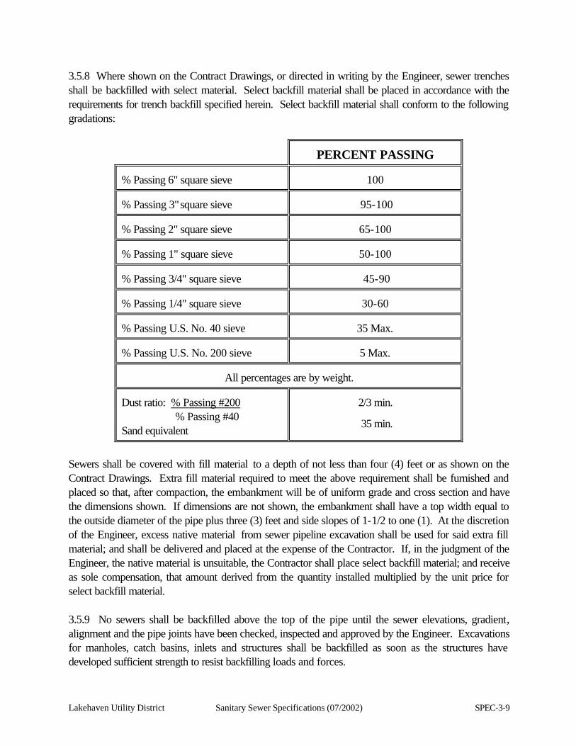
Lakehaven Utility District Sanitary Sewer Specifications (07/2002) SPEC-3-9
3.5.8 Where shown on the Contract Drawings, or directed in writing by the Engineer, sewer trenches shall be backfilled with select material. Select backfill material shall be placed in accordance with the requirements for trench backfill specified herein. Select backfill material shall conform to the following gradations:
PERCENT PASSING
% Passing 6" square sieve
100
% Passing 3" square sieve
95-100
% Passing 2" square sieve
65-100
% Passing 1" square sieve
50-100
% Passing 3/4" square sieve
45-90
% Passing 1/4" square sieve
30-60
% Passing U.S. No. 40 sieve
35 Max.
% Passing U.S. No. 200 sieve
5 Max.
All percentages are by weight.
Dust ratio: % Passing #200 % Passing #40 Sand equivalent
2/3 min.
35 min.
Sewers shall be covered with fill material to a depth of not less than four (4) feet or as shown on the Contract Drawings. Extra fill material required to meet the above requirement shall be furnished and placed so that, after compaction, the embankment will be of uniform grade and cross section and have the dimensions shown. If dimensions are not shown, the embankment shall have a top width equal to the outside diameter of the pipe plus three (3) feet and side slopes of 1-1/2 to one (1). At the discretion of the Engineer, excess native material from sewer pipeline excavation shall be used for said extra fill material; and shall be delivered and placed at the expense of the Contractor. If, in the judgment of the Engineer, the native material is unsuitable, the Contractor shall place select backfill material; and receive as sole compensation, that amount derived from the quantity installed multiplied by the unit price for select backfill material. 3.5.9 No sewers shall be backfilled above the top of the pipe until the sewer elevations, gradient, alignment and the pipe joints have been checked, inspected and approved by the Engineer. Excavations for manholes, catch basins, inlets and structures shall be backfilled as soon as the structures have developed sufficient strength to resist backfilling loads and forces.

SPEC-3-10 Sanitary Sewer Specifications (07/2002) Lakehaven Utility District
Lakehaven Utility District Sanitary Sewer Specifications (07/2002) SPEC-3-11
3.5.10 Temporary cribbing, sheeting or other timbering shall be removed during the process of backfilling, using methods that will not disturb the pipe, but shall remain in place until the backfill is of sufficient depth to stabilize the trench walls. Particular caution shall be used in pulling a trench box, where utilized. A cable will be used to secure the pipe while pulling a trench box, as necessary. 3.5.11 Trenches shall be closed at night unless otherwise approved by the governmental agency having jurisdiction, the Engineer and the General Manager of Lakehaven Utility District. Trenches that must remain open shall be suitably bridged or covered, as required by the Engineer, to permit access to homes or businesses by the inhabitants and service personnel. The Contractor shall cooperate with the fire official having jurisdiction concerning maintenance of access to all areas and shall notify him/her of all street restrictions and closures. Boring pits shall be covered at night and/or shall be adequately protected with lighted barricades. 3.6 TEMPORARY ROADWAYS 3.6.1 The Contractor shall construct all temporary access roadways and fills required for the project. Temporary access roads shall be constructed and maintained to provide adequate access, without detrimental effects to adjacent property. Failure of the Contractor to prevent dust nuisance will be just cause for the Owner to perform the necessary corrective work and to deduct the cost of performing this work from the monies due the Contractor. The Contractor shall have sole responsibility to assure that temporary roadways and fills adjacent to or over existing facilities is adequate for all uses, without causing damage to the existing facilities. In addition, the temporary roadway shall be brought to a smooth, even condition, free of bumps and depressions, and to a safe and satisfactory condition so as to allow use by public traffic. All temporary access roads and fills required for the project shall be removed prior to the completion of the work. 3.6.2 The Contractor shall be responsible for the adequacy of all bridges or other structures used during the construction of the project. The Contractor shall strengthen existing bridges or other structures used by him/her or provide temporary bridges or structures, if required by his/her construction procedures. 3.6.3 The Contractor shall provide water and/or a dust palliative and apply, as ordered by the Engineer, for the alleviation or prevention of dust nuisances. A water truck shall be assigned to the project for full-time use. All costs of which shall be merged in the various lump sum and unit prices bid. Should the Contractor elect to utilize gravel, or any bituminous product, as a means of providing and/or maintaining dust control, it shall be at his/her expense. Rock and bituminous products, as shown in the proposal, are intended to be utilized for roadway restoration and not for dust control.
SPEC-3-12 Sanitary Sewer Specifications (07/2002) Lakehaven Utility District
3.7 ADDITIONAL UNCLASSIFIED EXCAVATION 3.7.1 This unit of work is for payment of additional excavation and backfill, where ordered by the Engineer. Payment will be on an unclassified basis and no distinction shall be made between rock and earth excavation, insofar as payment is concerned. This unit of work will include payment for additional excavation in the event that a sewer line must be lowered from the grade and elevations shown on the Contract Drawings, when directed by the Engineer in writing. 3.7.2 Additional unclassified excavation shall comply with all requirements of these Specifications. 3.7.3 Unsuitable and surplus excavated material not incorporated in the improvement shall be disposed of by the Contractor at his/her own expense, unless otherwise designated in the Contract Special Provisions or on the Contract Drawings. 3.8 FLAGGERS, BARRICADES AND SIGNS 3.8.1 The Contractor shall be responsible for providing adequate flaggers, barricades, lights and signs for the protection of the work and the public at all times regardless of whether or not the flaggers, barricades, lights and signs are ordered by the District or the governmental agency having jurisdiction. The Contractor and his/her surety shall be liable for injuries and damages to persons and property suffered by reason of the Contractor's operations or any negligence in connection therewith. 3.8.2 Flaggers, barricades, signs and traffic control measures furnished or provided shall conform to standards established in the latest adopted edition of the "Manual on Uniform Traffic Control Devices," published by the U.S. Department of Transportation. 3.9 PUBLIC CONVENIENCE AND SAFETY 3.9.1 The Contractor shall conduct his/her operations with the least possible obstruction and inconvenience to the public, and he/she shall have under construction no greater length or amount of work than he/she can prosecute properly with due regard to the rights of the public. He/She shall not open up sections of the work and leave them unfinished, but he/she shall finish the work as he/she goes insofar as is practicable. 3.9.2 All public traffic shall be permitted to pass through the work with as little inconvenience and delay as possible. The Contractor shall keep existing roads and streets, adjacent to or within the limits of the project, open to traffic and maintained in a good and safe condition for traffic at all times. The Contractor shall remove any deposits or debris and shall repair any damage resulting from his/her operations.
Lakehaven Utility District Sanitary Sewer Specifications (07/2002) SPEC-3-13
3.9.3 Existing traffic signals and highway lighting systems shall be kept in operation for the benefit of the traveling public during progress of the work and the Contractor shall coordinate the continued routine maintenance of such existing systems with the governmental agency having jurisdiction. 3.9.4 Construction shall be conducted so that as little inconvenience as possible is caused to abutting property owners. Convenient access to driveways, houses, and buildings along the line of work shall be maintained; and temporary approaches to crossing or intersecting highways shall be provided and kept in good condition. When the abutting owners' access across the right-of-way line is to be eliminated and replaced under the contract by other access, the existing access shall not be closed until the replacement access facility is available. 3.10 ONE-WAY PILOTED TRAFFIC CONTROL THROUGH CONSTRUCTION ZONE 3.10.1 The construction of treated bases, surface treatments, and pavements sometimes requires permitting traffic to use a portion of the roadway during the progress of the work under prescribed one-way piloted traffic control. If this is the case, the Contractor shall confine his/her operations to one-half the roadway, permitting traffic on the other half. If, in the opinion of the Engineer, one-way piloted traffic is necessary, the Contractor will be required to furnish the flaggers, pilot car, and driver (piloting and flagging costs shall be borne by the Contractor). 3.10.2 Insofar as conditions will permit, the Contractor shall, at the end of each day, leave the work in such condition that it can be traveled through without damage to the work and without danger to traffic. The Engineer shall be the sole judge as to whether or not flagging and piloting can be dispensed with after working hours. In the event that flagging and piloting are required after working hours, as a result of carelessness or negligence on the part of the Contractor to properly condition the work at the end of the day, such piloting and flagging costs shall be borne by the Contractor. 3.11 CONSTRUCTION AND MAINTENANCE OF DETOURS 3.11.1 The Contractor shall construct, maintain in a safe condition, keep open to traffic, and remove detours and detour bridges that will accommodate traffic diverted from the roadway. The Contractor shall construct, maintain in a safe condition, and remove detour crossings of intersecting highways and temporary approaches. A minimum of two-way traffic shall be maintained, unless approved otherwise. 3.11.2 Detours caused by the Contractor's operations, or for the convenience of the Contractor, shall be constructed, maintained, and removed by the Contractor at his/her expense. Plans for these detours shall be submitted to the Engineer for approval. Surfacing and paving shall be consistent with the requirements of traffic.
SPEC-3-14 Sanitary Sewer Specifications (07/2002) Lakehaven Utility District
3.11.3 Upon failure of the Contractor to immediately provide, maintain, or remove detours or detour bridges, when ordered to do so by the Engineer, Lakehaven Utility District may, without further notice to the Contractor or his/her Surety, provide, maintain, or remove the detours or detour bridges and deduct the costs from any payments due or coming due the Contractor. 3.12 FILLS AND EMBANKMENTS 3.12.1 Plow areas to receive fills and embankments. Remove roots, sod and other extraneous materials. Place each layer of fill material over the entire length and width of the fill or embankment. Place in layers no more than eight (8) inches thick, loose measure. Compact with rollers or other Engineer approved means. Compact cohesion-less soils to at least 75 percent relative density as determined by ASTM D2049. Compact cohesive soils to at least 95 percent of maximum dry weight as determined by ASTM D1557. 3.12.2 Not less than one (1) test for each 20,000 square feet of area shall be taken for each layer. No additional layers shall be placed until the density of each layer in place has been approved. The cost of laboratory testing shall be paid solely by the Contractor. The independent testing laboratory shall meet the "Recommended Requirements for Independent Laboratory Qualification" published by the American Council of Independent Laboratories and approved by the Engineer. 3.12.3 Do not place fill in water, on frozen ground, or on other surfaces not approved by the Engineer. 3.12.4 Obtain materials required for backfill, fill, or embankments in excess of that available on the site from other sources. Include the cost of obtaining additional fill in the contract price. 3.13 EXISTING FACILITIES 3.13.1 It shall be the sole responsibility of the Contractor to safeguard all existing utilities, whether they are shown on the Contact Drawings or located in the field. Where the construction crosses or is adjacent to existing utilities, the Contractor shall exercise extreme care to protect such utilities from damage. 3.13.2 The Contractor shall be required to contact the utility locating service at 1-800-424-5555 prior to any ground breaking and incorporate the costs as an "incidental" to the project. 3.13.3 Prior to construction activities, the Contractor shall expose and verify the existing underground utilities, as required, in order to perform construction of the new improvements. 3.13.4 No payment will be made for the protection of existing utilities and any cost and expense incurred in protecting these utilities shall be included in the various unit prices bid under the Contract.
Lakehaven Utility District Sanitary Sewer Specifications (07/2002) SPEC-3-15
3.13.5 If any damage is done to an existing utility, the Contractor shall notify the utility company involved. 3.13.6 All damage done to existing improvements during the progress of the work on the structures covered by these Specifications shall be repaired or restored by the Contractor to the satisfaction of the Engineer, using for such repair materials and methods conforming to the requirements of the Specifications or standard practice of the Owner, and any additional instruction issued therefore by the Engineer, with the intent that such damaged improvements be restored to as good a condition as before damaged. If the Contractor fails to furnish the necessary labor and materials for such repair, when ordered, the Engineer may cause said labor and materials for such repairs to be furnished by other parties, and the cost thereof shall be deducted from such money as may be due the Contractor by reason of work performed or material furnished under these specifications.
Lakehaven Utility District Sanitary Sewer Specifications (07/2002) SPEC-4-1
SECTION 4
PIPELINE CONSTRUCTION 4.1 GENERAL 4.1.1 This section includes furnishing and installing all pipe materials for gravity sewers, side sewers, manhole drop structures and all other piping shown on the Contract Drawings or specified herein. Pipe sizes are nominal inside diameter unless otherwise noted. All sizes and types of pipe are noted on the Contract Drawings and specified herein. Where pipe is lined, the nominal diameter shall be the inside diameter of the cement mortar lining. 4.1.2 All pipe and fittings delivered to the job site shall be clearly marked to identify the material, class and thickness. All material shall be new and free of blemishes. Acceptance of pipe and accessories by the District will be based on load bearing tests, material tests and inspection of the complete products as specified hereinafter. Acceptance of installed piping will be based on inspection and leakage tests as specified hereinafter. 4.1.3 All pipe, fittings and accessories shall be designed for the service intended; shall be of rugged construction, of ample strength for all stresses which may occur during fabrications, transportation and erection and during continuous or intermittent operation; shall be adequately stayed, braced and anchored; and shall be installed in a neat and workmanlike manner. All piping shall be designed to withstand the test pressures specified. 4.1.4 The Contractor shall furnish and install all necessary guides, inserts, anchor and assembly bolts, washers and nuts, supports, gaskets, flanges and other appurtenant items shown on the Contract Drawings, specified herein or required for the proper installation and operation of the piping and piping accessories. 4.1.5 Anchor and assembly bolts and nuts shall be of ample size and strength for the purpose intended. Stainless steel bolts and nuts shall be used in moist or damp locations. Unless otherwise specifically noted, all bolts shall be standard machine bolts with cold-pressed hexagon nuts. Bolts in submerged locations, embedded in concrete or buried in earth shall be stainless steel. Stainless steel for bolts shall conform to ASTM F593, Alloy Group 2. Stainless steel for nuts shall conform to ASTM F594, Alloy Group 2. 4.2 MATERIAL LIST The Contractor shall submit to the Engineer a list of materials in accordance with the proper section of the Contract Special Provisions. The list shall include all items of pipe, pipe jointing materials, fittings and accessories, the name of the manufacturer of each item, the Contract Drawing or Specification reference in the Contract, and the specification to which each item is manufactured. The material list shall be reviewed before any pipe is installed.

SPEC-4-2 Sanitary Sewer Specifications (07/2002) Lakehaven Utility District
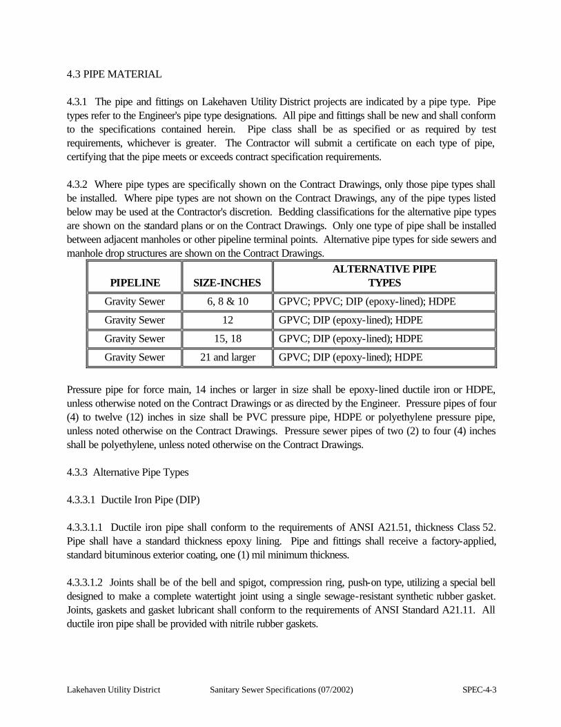
Lakehaven Utility District Sanitary Sewer Specifications (07/2002) SPEC-4-3
4.3 PIPE MATERIAL 4.3.1 The pipe and fittings on Lakehaven Utility District projects are indicated by a pipe type. Pipe types refer to the Engineer's pipe type designations. All pipe and fittings shall be new and shall conform to the specifications contained herein. Pipe class shall be as specified or as required by test requirements, whichever is greater. The Contractor will submit a certificate on each type of pipe, certifying that the pipe meets or exceeds contract specification requirements. 4.3.2 Where pipe types are specifically shown on the Contract Drawings, only those pipe types shall be installed. Where pipe types are not shown on the Contract Drawings, any of the pipe types listed below may be used at the Contractor's discretion. Bedding classifications for the alternative pipe types are shown on the standard plans or on the Contract Drawings. Only one type of pipe shall be installed between adjacent manholes or other pipeline terminal points. Alternative pipe types for side sewers and manhole drop structures are shown on the Contract Drawings.
PIPELINE
SIZE-INCHES
ALTERNATIVE PIPE TYPES
Gravity Sewer 6, 8 & 10 GPVC; PPVC; DIP (epoxy-lined); HDPE
Gravity Sewer 12 GPVC; DIP (epoxy-lined); HDPE
Gravity Sewer 15, 18 GPVC; DIP (epoxy-lined); HDPE
Gravity Sewer 21 and larger GPVC; DIP (epoxy-lined); HDPE
Pressure pipe for force main, 14 inches or larger in size shall be epoxy-lined ductile iron or HDPE, unless otherwise noted on the Contract Drawings or as directed by the Engineer. Pressure pipes of four (4) to twelve (12) inches in size shall be PVC pressure pipe, HDPE or polyethylene pressure pipe, unless noted otherwise on the Contract Drawings. Pressure sewer pipes of two (2) to four (4) inches shall be polyethylene, unless noted otherwise on the Contract Drawings. 4.3.3 Alternative Pipe Types 4.3.3.1 Ductile Iron Pipe (DIP) 4.3.3.1.1 Ductile iron pipe shall conform to the requirements of ANSI A21.51, thickness Class 52. Pipe shall have a standard thickness epoxy lining. Pipe and fittings shall receive a factory-applied, standard bituminous exterior coating, one (1) mil minimum thickness. 4.3.3.1.2 Joints shall be of the bell and spigot, compression ring, push-on type, utilizing a special bell designed to make a complete watertight joint using a single sewage-resistant synthetic rubber gasket. Joints, gaskets and gasket lubricant shall conform to the requirements of ANSI Standard A21.11. All ductile iron pipe shall be provided with nitrile rubber gaskets.
SPEC-4-4 Sanitary Sewer Specifications (07/2002) Lakehaven Utility District
4.3.3.1.3 Fittings shall conform to the requirements of ANSI Standard A21.10, except for the laying length, and shall utilize bell and spigot joints as herein specified. Fittings shall have a standard thickness epoxy lining. Fittings shall receive a factory-applied, standard bituminous exterior coating, one (1) mil minimum thickness. 4.3.3.1.4 Where flanged joints are shown on the Contract Drawings, they shall utilize cast iron, screwed-on flanges, 125 point class with oversized hub and conforming in all other respects to the requirements of ANSI B16.1. Flanges shall be refaced before shipment. Gaskets shall be ring-type gaskets (not full face), Johns Mansville, service sheet, style 60, 1/16-inch thick, equivalent gasket by the Crane Company, or equal. A non-stick parting agent shall be applied to both sides of the gasket by the gasket manufacturer. No oil or compound shall be used in the field for gasket installation. Bolts and nuts shall be standard machine bolts with square heads and cold-pressed hexagon nuts. Studs with two (2) cold-pressed hexagon nuts shall be used where required or necessary. Bolts and nuts shall conform to the requirements of ASTM Designation A-307, Grade B and ANSI Standard B18.2. Stud bolts and nuts shall conform to the requirements of ASTM Designation A-193, Grade B7, ANSI Standard B16.5 and ANSI Standard B18.2. Bolts and nuts shall be zinc-coated steel or stainless steel. Watertight plugs shall be U.S. Pipe & Foundry Company No. U-364, the equivalent Pacific States Cast Iron Pipe Company item, or equal. 4.3.3.1.5 Where mechanical joints and fittings are shown on the Contract Drawings, they shall conform to ANSI A21.10 and ANSI A21.11. 4.3.3.1.6 All ductile iron pipe and fittings shall be provided and installed with a epoxy lining applied to all exposed interior surfaces, unless otherwise specified on the Contract Drawings. The lining shall be as manufactured by Madison Chemical Industries, Inc., Pacific States Cast Iron Pipe Company, or an approved equal. The epoxy lining must be a high build multi-component Amine cured Novalac Epoxy Lining (Protecto 401 Ceramic Epoxy). 4.3.3.1.6.1 Surface preparation. Surface preparation shall be to the lining manufacturer’s recommendations and specifications. All surfaces to be lined shall be cleaned to a near-white metal finish (SSPC-SP10) as applied to ductile iron pipe and fittings. All surfaces to be lined shall be completely dry, free of moisture, dust, grease, or any other deleterious substances, at the time the lining is applied. 4.3.3.1.6.2 Thickness. The dry film thickness (DFT) of internal lining shall be 40 mils (0.040 inch) nominal. Thickness determinations using a Type 1 magnetic thickness gauge shall be conducted in accordance with Steel Structures Painting Council SSPC-PA2 Specification as applied to ductile iron pipe and fittings. 4.3.3.1.6.3 Joints. In order to minimize potential dimensional and assembly problems, the coating thickness on sealing areas in the bell socket interior and on the spigot end of the pipe exterior shall be 6 to 8 mils (0.008 inch) nominal with a maximum of 10 mils (0.010 inch). Thicker coatings in these areas are acceptable, if it is demonstrated that joint dimensions are within allowable tolerances after coating.
Lakehaven Utility District Sanitary Sewer Specifications (07/2002) SPEC-4-5
Depending on the application process and intended usage, the joint coating material shall be Protecto Joint Compound for the ceramic epoxy coating, performed in accordance with the manufacturer's recommendations. 4.3.3.1.6.4 Repair and Field Touchup. Repair and touchup materials shall be Protecto Joint Compound for the ceramic epoxy coating. Repairs and touchup shall be performed in accordance with the manufacturer's recommended repair and touchup procedures. All field-cut ends shall be repaired and sealed prior to installation. 4.3.3.2 Gravity Polyvinyl Chloride Pipe (GPVC) 4.3.3.2.1 GPVC ASTM D-3034/F-679 Gravity polyvinyl chloride pipe shall be plasticized polyvinyl chloride pipe with integral wall bell and spigot joints and shall be suitable for use as a gravity conduit for the conveyance of domestic sewage. Pipe in sizes from 4- inch through 15-inch and fittings shall conform to the requirements of ASTM Designation D-3034, Type PSM SDR-35, except as modified herein or as shown on the plans. 18-inch pipe and larger, and fittings, shall conform to the requirements of ASTM F679, SDR-35. Deflection greater than five (5) percent of inside diameter of pipe, installed, will not be accepted. 4.3.3.2.1.1 Joints for pipe and fittings shall utilize sewage-resistant synthetic rubber gaskets conforming to the requirements of ASTM Designation F-477. The gaskets shall be the sole element depended upon to make the joint flexible and watertight. Provisions for expansion and contraction shall be made at each joint. The assembled joint shall withstand a pressure to ten (10) psi for a period of one (1) hour without leakage in the concentric alignment and in the manufacturer's recommended maximum deflected position. 4.3.3.2.1.2 Pipe manufactured greater than ten (10) months prior to actual installation will not be permitted. Pipe older than six (6) months shall be protected from exposure to ultraviolet light. 4.3.3.2.1.3 Pipe and fittings shall be manufactured by Johns Mansville, Certain-Teed or approved equal. 4.3.3.2.2 GPVC AWWA C-900/C-905 Gravity polyvinyl chloride pipe shall be plasticized polyvinyl chloride pipe with integral wall bell and spigot joints and shall be suitable for use as a gravity conduit for the conveyance of domestic sewage. Pipe in sizes from 4-inch through 12-inch and fittings shall conform to the requirements of AWWA Designation C900, DR-18, except as modified herein or as shown on the plans. 14-inch through 36-inch, and fittings, shall conform to the requirements of AWWA C-905, DR-18, except as modified herein or as shown on the plans. Deflection greater than five (5) percent of inside diameter of pipe, installed, will not be acceptable.
SPEC-4-6 Sanitary Sewer Specifications (07/2002) Lakehaven Utility District
4.3.3.2.2.1 Joints shall meet the requirements of ASTM D-3139, using a restrained rubber gasket conforming to ASTM F-477. 4.3.3.2.2.2 Pipe manufactured greater than ten (10) months prior to actual installation will not be permitted. Pipe older than six (6) months shall be protected from exposure to ultraviolet light. 4.3.3.3 Pressure Polyvinyl Chloride Pipe (PPVC) 4.3.3.3.1 Pressure polyvinyl chloride pipe shall be rigid plasticized polyvinyl chloride pipe suitable for use as a pressure conduit for the conveyance of domestic sewage. The pipe shall be suitable for use at a maximum hydrostatic pressure of 200 psi at 73 degrees Fahrenheit. Pipe shall conform to the requirements of ASTM Designation D-2241-96, except as modified herein or as shown on the plans. 4.3.3.3.2 All pressure polyvinyl chloride pipe shall be Schedule 40 or greater. 4.3.3.3.3 The material used to produce the pipe and fittings shall be clean, virgin material conforming to the requirements of ASTM Designation D-1784, Class 12453-B. 4.3.3.3.4 Joints for pipe and fittings shall utilize sewage-resistant synthetic rubber gaskets conforming to the requirements of ASTM Designation F-477. The gaskets shall be the sole element depended upon to make the joint flexible and watertight. Provisions for expansion and contraction shall be made at each joint. 4.3.3.3.5 Pipe manufactured greater than ten (10) months prior to actual installation will not be permitted. Pipe older than six (6) months shall be protected from exposure to ultraviolet light. 4.3.3.3.6 Pipe and fittings shall be as manufactured by Johns Mansville, Certain-Teed or approved equal. 4.3.3.4 High Density Polyethylene Pipe (HDPE) 4.3.3.4.1 High Density Polyethylene gravity sewer pipe shall conform to ASTM Designation F894-85, or later revision, for polyethylene large-diameter profile wall sewer and drain pipe. Joints shall be gasketted type. The pipe resin shall conform to all requirements of ASTM D1248, Type III, Class C, Grade P34, with a PPI rating of 3408. The long-term hydrostatic strength shall be 1250 psi, and the hydrostatic design stress shall be 650 psi, as determined by ASTM D2837. Material strength and modules of elasticity shall meet the requirements of cell classification PE 345434C or higher, ASTM D3350. Minimum ring stiffness constants for various pipe diameters are shown on the "pipe schedule" provided in the Contract Drawings.
Lakehaven Utility District Sanitary Sewer Specifications (07/2002) SPEC-4-7
4.3.3.4.2 Prior to installation, the manufacturer shall provide written certification that the material was manufactured, sampled, tested, and inspected in accordance with ASTM F894 and found to meet all requirements. Copies of all test results shall be provided with the certification. The Engineer shall have free access to the testing and inspection areas of the manufacturer's plant. 4.3.3.4.3 Gaskets shall be rubber and molded or, if approved by the Owner, produced from an extruded shape approved by the pipe manufacturer and spliced into circular form. The gaskets shall comply with the physical requirements specified in the non-pressure requirements of ASTM Specification F-477. The lubricant used for assembly shall have no detrimental effect on the gasket or the pipe. 4.3.3.4.4 The average nominal inside diameter shall be true to the specified pipe size within ± 1/4-inch. Standard laying lengths shall be 20 feet (±2"). 4.3.3.4.5 Each piece of pipe shall be clearly marked with the pipe size, class, profile number and production code. 4.3.3.4.6 The pipe shall be stored, loaded, unloaded, installed, bedded, compacted, and backfilled in complete accordance with the manufacturer's recommendations, unless otherwise specifically directed or authorized, in writing, by the Engineer. 4.3.3.4.7 A manufacturer's representative shall be on site during start-up construction for a minimum of 8 hours, for each crew utilized, to instruct work crews and ensure compliance with his/her company's installation regulations. Additionally, he/she shall remain on site for this purpose until such time that he/she feels the Contractor has demonstrated his competence in the method employed by the Contractor for this type of pipe installation. 4.3.3.4.8 The bedding material shall be compacted to a minimum 90% of the Standard Proctor Density per ASTM D-698. Mechanical compaction will be required. 4.3.3.4.9 HDPE pipe shall be white or near white in color. 4.3.3.5 Polyethylene Pressure Pipe 4.3.3.5.1 Polyethylene pressure pipe shall be high density polyethylene (HDPE) plastic pipe with fittings suitable for use as a pressure conduit. The pipe shall conform to all requirements of ASTM D148, Type III, Class C, Category 5, Grade P34, with a PPI rating of PE 3406. The pipe shall have a working pressure rating of 145 psi, SDR11 and withstand without failure a minimum burst pressure of 560 psi when applied in 60 to 70 seconds with water at 73 degrees Fahrenheit, in accordance with ASTM D1599. The long-term hydrostatic strength shall be 1450 psi and hydrostatic design stress of 730 psi, as determined by ASTM D2837. The melt index shall be less than 0.25 as determined by ASTM D1238. The environmental stress crack resistance shall allow no cracks after 1,000 hours as determined by ASTM D1693.
SPEC-4-8 Sanitary Sewer Specifications (07/2002) Lakehaven Utility District
4.3.3.5.2 Polyethylene pressure pipe joints shall be joined by a thermal butt fusion system in accordance with the manufacturer's requirements. 4.4 PIPING ACCESSORIES 4.4.1 Flexible Couplings Couplings for joining different pipe types shall consist of a cast iron coupling system; or of a sewage-resistant synthetic rubber or polyvinyl chloride sleeve, Type 301 or better, with stainless steel bands and a tightening mechanism designed to compress the sleeve to form a watertight and airtight seal when the joint is assembled as approved by the Engineer. Joints made using couplings shall pass the tests specified for gravity pipelines in Section 6 of these specifications. Couplings shall be as manufactured by Rockwell International, or approved equal. Couplings may only be used where proposed pipelines connect to existing pipeline stub-outs. No Fernco-type couplings shall be used on mainline pipe construction. 4.5 PIPE LAYING 4.5.1 All pipe utilizing bell and spigot-type joints shall be laid continuously upgrade with the bell of the pipe forward, unless specifically shown otherwise on the Contract Drawings. Each length of pipe shall be bedded firmly into granular bedding material as specified in Section 3.4 of these specifications. Each length of pipe shall have a true bearing for its entire length. A depression in the bedding material no larger than necessary to accommodate the pipe shall be excavated at each joint location. Adjustment to line and grade shall be made by scraping away, filling in and tamping the bedding material to provide true grade to fit the barrel of the pipe. No wedging or blocking up of pipe shall be permitted. 4.5.2 Both bell and spigot shall be clean before the joint is made, and care shall be taken that nothing but the joint material and lubricant enters the joint. Joints shall be made in accordance with the manufacturer's recommendations. Care shall be exercised to insure that the gasket is fully seated and that the insertion of the spigot end is complete and complies fully with the manufacturers recommendations for installation. Particular attention is called to the high coefficient of expansion of polyvinyl chloride pipe and the need to carefully observe necessary joint clearances as indicated by pipe markings. 4.5.3 After making the joint, the pipe shall be rigidly secured in place by backfilling to the top of the pipe, on each side of the pipe, at the center of the section, using bedding material or initial backfill material in accordance with the designated bedding condition. Due to the light weight of polyvinyl chloride pipe, additional care shall be taken during the initial backfilling, so as not to disturb, raise, lower or laterally move the pipe. 4.5.4 Caps for stubs shall be air-tight, compatible to the pipe joint and shall be in accordance with the pipe manufacturer's recommendation. Wood caps will not be permitted. Blocking of caps shall be
Lakehaven Utility District Sanitary Sewer Specifications (07/2002) SPEC-4-9
provided as required. 4.5.5. When pipe laying is not in progress, the forward end of the pipe shall be kept effectively closed with a temporary plug. Care shall be taken to prevent damage to pipe or pipe ends. Any pipe or pipe ends damaged shall be removed and discarded. 4.5.6 All pipelines shall be laid to the line and grade shown on the Contract Drawings, unless otherwise directed by the Engineer. Variance from established line and grade for gravity sewer lines shall not be greater than 1/32 of an inch per inch of pipe diameter and shall not exceed 1/2 inch; provided that such a variation does not result in a level or reverse sloping pipe invert. Variance in the invert elevation between adjoining pipe ends due to non-concentricity of joining and pipe interior surfaces shall not exceed 1/64 of an inch per inch of pipe diameter or 1/2 inch maximum; provided that such a variation does not result in a level or reverse sloping pipe invert. 4.5.7 Survey line and grade-control hubs will be provided by the Contractor for his/her use in constructing all pipelines to the proper grade and alignment as shown on the Contract Drawings. The Contractor shall transfer line and grade and control his/her work. In case the referenced methods are impractical, the Contractor may control his/her line and grade by the use of approved surveying instruments operated by qualified personnel. The Contractor shall constantly check line and grade of the pipe and, in the event they do not meet specified limits, the work shall be immediately stopped and the cause remedied before proceeding with the work. 4.5.8 Pressure sewer pipe shall be laid in accordance with the manufacturer's requirements and the line and grade shown on the Contract Drawings, unless otherwise directed by the Engineer. Mud, silt, gravel and other foreign material shall be kept out of the pipe and joining surfaces. The pipe shall be laid at uniform grade with no sag or overbends between high and low points. 4.5.8.1 The Contractor shall install a continuous ribbon of warning tape one (1) foot below the finished grade directly above the sewer force main. The warning tape used shall conform to the requirements for marker tape under Section 4.6.3. of these specifications. 4.5.8.2 Concrete thrust blocks shall be required at all force main bends, as detailed on the Contract Drawings and/or as directed by the Engineer. 4.6 SERVICE FITTINGS AND SIDE SEWER STUBS 4.6.1 Regardless of the locations shown on the Contract Drawings, all service fittings and side sewer stubs shall be installed at the locations directed by the Engineer. The Engineer will furnish to the Contractor the station of the service fittings and calculate the cut to the invert of the side sewer stubs at the right-of-way or easement line. 4.6.2 The known existing basement locations are indicated on the Contract Drawings. There is no guarantee that all basements are shown or that the locations shown are accurate. Where required by
SPEC-4-10 Sanitary Sewer Specifications (07/2002) Lakehaven Utility District
the Engineer, the Contractor shall construct side sewer stubs to serve basements, whether or not their locations are shown on the Contract Drawings. Where basements are not a factor, the side sewer stubs shall be placed at a depth adequate to serve the property in question, with a preferred depth of five (5) to eight (8) feet for enhanced access. Minimum grade for side sewer stubs is 2%. Maximum grade for side sewer stubs is 200%. 4.6.3 Side sewer stubs shall be marked with plastic film marking tape. Tape shall be an inert plastic film highly resistant to alkalis, acids, or other destructive chemicals likely to be encountered in soils. Tape shall be a minimum of two (2) inches in width, brightly colored and shall bear an imprint to the effect that a sewer pipeline lies below. Tape shall have a metalized foil core to enable detection with electronic instruments. 4.6.4 Plastic marking tape shall be buried in the pipe trench, directly over the pipe, at a depth of 1-1/2 to two (2) feet. Tape shall extend the full length of the side sewer stub from the sewer main to the plugged end at the right-of-way or easement line. 4.6.5 All side sewer stubs shall be marked with a 2" X 4" wood, plastic or metal stake placed at the end of the side sewer stub. The 2" X 4" stake shall be painted with a white oil-based enamel base coat. The label "Sanitary Side Sewer" and depth to invert shall be clearly marked with black enamel paint. 4.7 JACKING OR AUGERING CONSTRUCTION 4.7.1 Jacking or augering beneath existing structures, across railroad rights-of-way, across highway rights of way, under stream channels or other locations indicated on the Contract Drawings or as directed by the Engineer shall be of sufficient size, height and width to permit the installation of the pipe and/or conduits, and to permit ample room for the work and safety of the workmen. The Contractor shall make his/her own determination of site conditions, local jurisdiction requirements, and shall select a construction method compatible with these conditions. Details of the methods to be employed shall be submitted to the Engineer for approval. 4.7.2 All work performed beneath existing structures, rights-of-way or stream channels shall be performed in accordance with the requirements and/or regulations of the parties or agencies having jurisdiction over these locations. The Contractor shall contact the parties or agencies prior to starting work and shall meet all requirements of the parties or agencies with regard to insurance, methods of construction, and the safety precautions to be taken in performing the jacking or augering work, and written confirmation shall be submitted to the Engineer. All costs involved in meeting these requirements shall be included in the pipeline unit price and no additional compensation will be allowed. 4.7.3 The steel casing pipe shall be of sufficient strength to meet the loading conditions. Loading for highway and pavement tunnels shall be based upon continuous load carrying structures for the height of cover under H-20 loading. Loading for railroad tunnels shall be based on continuous load carrying structures for the height of cover under Cooper E-80 loading. Voids between the ground and the casing pipe shall be pressure grouted.
Lakehaven Utility District Sanitary Sewer Specifications (07/2002) SPEC-4-11
4.7.4 Materials Steel casing pipe shall be fabricated from steel conforming to the requirements of ASTM Designation A-36. Wall thickness shall be a minimum of 1/2-inch or as shown on the Contract Drawings. Pipe shall be of all-welded construction and shall be watertight. Successive lengths of pipe shall be jointed with a continuous weld. 4.7.5 Installation 4.7.5.1 Jacking and receiving pits or trenches shall be excavated at the locations shown on the Contract Drawings and shall not exceed the limits specified without written authorization from the Engineer. Excavation shall be of sufficient size to accommodate pipe and jacking or augering machinery. 4.7.5.2 Pipe shall be augered or jacked accurately to the specified line and grade. Pipe shall be jacked up grade unless otherwise shown on the Contract Drawings. Once jacking operations are started, work shall be carried on in successive shifts until completed, to guard against "freezing" of the line due to settlement and compaction of surrounding soil. If the Contractor chooses to work less than 24 hours per day, or if noise prohibits working at night, the Contractor does so at his/her own risk. The District shall not be responsible for any “freezing” of the casing or any additional work that may be necessary if “freezing” occurs. 4.7.5.3 Steel casing pipe, augered or jacked into place, shall be used where shown on the Contract Drawings. Casing pipe shall have a minimum wall thickness as stated herein or as shown on the Contract Drawings. Details of the methods to be employed shall be submitted to the Engineer for approval. The submittal shall include a listing of equipment required for the work. The approval of procedure and equipment by the Engineer shall not relieve the Contractor of responsibility, or waive or modify any of the provisions of the Contract. 4.7.5.4 Pipe welds shall conform to AWWA C-206. Pipe joints shall be welded only by welding operators who have been qualified in accordance with AWWA C-206. Not less than three weeks prior to field welding, the Contractor shall submit to the Engineer written welding procedures and evidence of welder qualification as described in AWWA C-206, Sections 3.2 and 3.3. Upon completion of welding, the Contractor shall furnish the Owner an Affidavit of Completion as described in AWWA C-206, Section 1.5. Weld filler material for field welds shall be low-hydrogen type, AWS A5.1, E7018 stick rod or AWS 5.2, E-71T-11 wire-feed type, unless otherwise approved by the Engineer. Metal surfaces at welded joints shall be kept dry and the work area covered with temporary shelters to keep rain, wind, and dew away from the weld area. All welds shall be visually inspected in accordance with AWS B1.11 and AWS D1.1-90. Defective welds shall be chipped out and rewelded. The Contractor shall retain an independent, AWS-certified welding inspector to perform all welding inspections. The Contractor shall submit a copy of the inspector's certification certificate to the Engineer prior to field welding.
SPEC-4-12 Sanitary Sewer Specifications (07/2002) Lakehaven Utility District
4.7.5.5 Before commencing augering or jacking operations, the Contractor shall have all necessary equipment at the site, including grouting equipment. Grouting shall commence immediately upon conclusion of jacking operations. Grouting equipment shall effectively mix and agitate the grout and force the grout into holes at the specified pressure. Grout shall be pumped with a duplex piston-type pump. Equipment shall include flow meter and pressure gauges. Grouting hose and grout supply line shall be not less than 1-1/2 inches in nominal diameter. Grouting equipment operation shall provide for continuous grout circulation in the system and shall allow accurate control of the pressure by operation of a valve on the grout return line. 4.7.5.6 Grouting equipment and lines shall be maintained in continuous circulation during the grouting operation. Equipment and lines shall be maintained in good operational condition to provide uninterrupted service during grouting. Grout for filling annular spaces shall be injected through holes in the casing pipe provided with connection devices for the grout hose. The Contractor shall provide such holes and connection devices to fill areas of annular spaces and where directed by the Engineer. Grout shall be injected at a pressure of approximately, but not more than, 25 pounds per square inch or a pressure, expressed in pounds per square inch, numerically equal to one half the vertical distance, expressed in feet, from the ground surface to the top of encasement. In addition, the grouting pressure shall not exceed that which might cause damage to existing facilities. Grouting shall be performed continuously until completed for each location. 4.7.5.7 Grout shall be a mixture of Portland cement, sand, and water. Portland cement shall be Type II. Sand shall pass a standard No. 8 mesh sieve and 45 percent, by weight, shall pass a standard No. 40 mesh sieve. Mix of grout shall be varied as required to fill the designated spaces and shall be subject to the Engineer's approval. Grout shall be free flowing with pressure up to 25 pounds per square inch, but shall be stiff enough to seal minor cracks and joints and fill empty spaces. 4.7.5.8 Special care shall be taken during the installation of the pipe to ensure that no settlement of adjacent areas occurs. Any such settlement caused by the placement of the pipe shall be the Contractor's responsibility. The Contractor shall repair all areas so affected, as directed by the Engineer, at the Contractor's own expense. In the event that the pipe is damaged during the installation and the defects cannot be corrected to the satisfaction of the Engineer, the Contractor shall be required to remove and replace the pipe at the Contractor's own expense. No additional payment will be made for the replacement or realignment of the pipe. 4.7.5.9 The Contractor shall make every attempt to probe the work site, to insure that he/she will have the proper equipment for the materials to be encountered. Any obstruction encountered during the jacking operation shall be considered incidental to the contract. The Contractor may be required to relocate the alignment if necessary.
Lakehaven Utility District Sanitary Sewer Specifications (07/2002) SPEC-4-13
4.7.6 Pipe Support 4.7.6.1 Sewer pipe in sizes up to ten (10) inches, to be installed in casing, shall be supported throughout its length on wooden skids or as shown on the Contract Drawings or by a method recommended by the pipe manufacturer. Skids shall be of thoroughly seasoned Western Red Cedar or Douglas Fir of the dimensions necessary to achieve the specified pipe grade. Skids shall be pressure treated with an approved preservative. Skids shall be fastened to the sewer pipe with steel bands. Alternative support skids recommended by the pipe manufacturer must be submitted to the District in writing, along with the manufacturer's installation requirements, for District review and approval. 4.7.6.2 Alternately, prefabricated steel pipe supports may be used. Pipe supports shall consist of a 12 inch wide steel band bolted around the pipe barrel and fitted with glass reinforced plastic runners. Steel band shall be of minimum 14 gauge thickness and shall be coated with heat-fused polyvinyl chloride. Minimum coating thickness shall be 0.010 inches. Runners shall be of sufficient size to allow backfill material, as specified below, to be placed under the bell. Prefabricated steel supports shall be placed at the bell and spigot ends and at the midpoint of the sewer pipe. Prefabricated steel pipe supports shall be equal to PSI Model C12G, as manufactured by the Pipeline Seal and Insulator Company, Burbank, California. The Contractor shall submit shop drawings to the Engineer for approval prior to installation. 4.7.6.3 Alternately, steel rails may be used to support the carrier pipe. If steel rails are used, they are to be embedded in concrete to the invert of the casing pipe as shown on the Contract Drawings so as to assure proper grade and alignment of the carrier pipe. Rails shall be positioned so as to allow for placing of backfill, and to prevent this carrier pipe from contact with the casing pipe. Contractor shall submit Shop Drawings in accordance with the conditions of the Contract for approval by the Engineer. 4.7.6.4 After installation of sewer pipe, and after verification of grade, the annular space surrounding the pipe shall be backfilled. Backfill material shall be clean, dry sand or concrete grout, pneumatically placed. The Contractor shall test the pipe in accordance with the requirements of Section 6 of these specifications prior to and after placement of the backfill material. 4.7.6.5 Sewer pipe shall have a joint outside the casing pipe within 1/2 pipe diameter from each end of the casing. 4.7.7 Following backfilling, the ends of the casing shall be sealed. End seals shall be flexible, waterproof, synthetic rubber seals and shall be fastened to both casing and sewer pipe with stainless steel bands or other approved means.
SPEC-4-14 Sanitary Sewer Specifications (07/2002) Lakehaven Utility District
4.8 GROUNDWATER SURGE RELIEF LINES Install groundwater surge relief lines where shown on the Contract Drawings or as directed by the Engineer. Groundwater surge relief lines shall be installed using 6- inch, perforated, smooth-walled PVC pipe, bedded with pea gravel in accordance with Class B bedding for flexible pipe, buried at a depth of approximately four (4) feet and connected to a catch basin, drywell or other drainage feature as shown on the Contract Drawings or otherwise directed by the Engineer. Pipe shall be the same as for gravity sewer pipeline, except that it shall be perforated. Groundwater surge relief lines are to be laid across the trench area, but are in no way to be connected to any sanitary sewer lines. The buried end of this line shall be plugged. All costs for materials and installation shall be included in the unit prices for gravity sewer pipelines.
Lakehaven Utility District Sanitary Sewer Specifications (07/2002) SPEC-5-1
SECTION 5
MANHOLE CONSTRUCTION 5.1 GENERAL 5.1.1 This section includes furnishing and installing all materials required to construct manholes, as detailed on the Contract Drawings. 5.1.2 Standard manholes shall be installed with synthetic rubber gaskets; where high groundwater is encountered or, at the direction of the Engineer, a second sealant-type gasket as described in Section 5.3.6 of these specifications shall be required. 5.2 MATERIAL LIST 5.2.1 The Contractor shall submit to the Engineer a list of materials in accordance with the appropriate section of the Conditions of the Contract. The list shall include all items of material for manholes, jointing material, fittings and accessories, the name of the manufacturer of each item, the specific contract reference, and the Standard Specification to which each item is manufactured. The material list shall be approved by the Engineer before any manholes are installed. 5.2.2 The Contractor shall also submit shop drawings for manhole frames and covers and for drop manholes for approval. 5.3 MATERIALS 5.3.1 Manholes shall be constructed either entirely of precast concrete sections or of precast concrete sections on a cast-in-place base. 5.3.2 Cast-in-place concrete and cement grout shall be as specified in Section 7.3.8 of the specifications. 5.3.3 Steel lifting loops or hooks for precast components shall be removed to a depth of one (1) inch below the surface of the concrete and the concrete shall be patched. Lift holes shall be solidly filled with dry pack grout. 5.3.4 Cast-in-place manhole bases shall be plain concrete, poured around the sewer pipe laid through the manhole. Base dimensions shall be equivalent to those for precast bases. Pipe crowns shall be removed and channeling shall be completed as specified in Section 5.3.8.6 of these specifications. The bottom precast riser section shall be installed before the concrete has set and shall be grouted or otherwise caulked in place to produce a watertight joint.
SPEC-5-2 Sanitary Sewer Specifications (07/2002) Lakehaven Utility District
5.3.5 Precast Components 5.3.5.1 Precast components shall conform to the requirements of ASTM Designation C-478. All Portland Cement used in the manufacture of the precast sections shall conform to the requirement of ASTM Designation C150 and shall be Type II or Type V. 5.3.5.2 Precast Base Sections. 5.3.5.2.1 Precast base sections shall conform to the requirements for precast riser sections, except that a reinforced base slab shall be cast monolithically with the walls or otherwise constructed to achieve a watertight structure. Base slab thickness shall be six (6) inches, minimum. Base slabs shall be reinforced with No. 4 steel bars on 12 inch centers placed in the middle third of the slab thickness and extending into the wall section of the base. The walls of the base section shall be reinforced in accordance with ASTM C478. Unless otherwise indicated on the Contract Drawings, or as directed by the Engineer, openings for pipe: up to 21-inch diameter may be provided in 48-inch base sections; up to 36-inch diameter may be provided in 54-inch base sections; up to 42-inch diameter may be provided in 72-inch base sections; and, up to 60-inch diameter may be provided in 96-inch base sections. 5.3.5.2.2 The GU Manhole Liner system, as manufactured by GU Manhole Liner LTD, Aldergrove, B.C., shall be utilized for all pipe connections, unless otherwise approved by the District. The GU liner shall be of one piece construction and of unlayered and homogenous fiberglass reinforced plastic (F.R.P.) with: (1) full flow channels with side walls to the crown of the pipe; (2) watertight gasketted bells to suit specific pipe types and grade alignment; (3) inner surface of the bench to have an anti-skid surface; and (4) the outer surface of the liner to be sand coated and have steel spirals bonded to the F.R.P. Installation of the GU Manhole Liner to concrete manhole bases shall be in accordance with the manufacturer's specifications and these Contract Documents. 5.3.5.2.3 Stubs shall be provided in the locations shown on the Contract Drawings. Positioning of the stubs shall accommodate the pipe size, invert elevations and direction of future sewer extensions indicated on the Contract Drawings. 5.3.5.3 Standard precast riser sections shall consist of circular sections in standard nominal inside diameters of 48, 54, 72, and 96 inches. Reinforcement shall be in accordance with ASTM C-478. Minimum height of a riser section shall be one (1) foot. Heights of riser and base sections shall be arranged so no pipes pass through the joining surfaces. Openings for pipe shall be circular, tapered toward the inside of the section, and shall be of the minimum size possible to accommodate the pipe to be inserted and to effectively seal the joint. 5.3.5.4 The taper section (cone) shall be eccentric, tapering from 48 inches, 54 inches, or 60 inches inside diameter to 24 inches inside diameter and shall be between 18 inches and 36 inches high. Joining to the riser sections shall be similar to joining between riser sections, but the top surface shall be flat and at least five (5) inches wide, radially, to receive grade rings.
Lakehaven Utility District Sanitary Sewer Specifications (07/2002) SPEC-5-3
5.3.5.5 Reductions from 72 or 96 inches to 48 inches shall be made by means of flat slab reducing sections as shown on the Contract Drawings. The section shall be a minimum of eight (8) inches thick for 72-inch manholes and 12 inches thick for 96-inch manholes and shall conform to the outer dimensions of the section on which it will be placed. The 48-inch opening shall be as located on the Contract Drawings or as directed by the Engineer. Reinforcing shall be as shown on the Contract Drawings. 5.3.5.6 Grade rings above the taper section shall be 24 inches inside diameter and shall be between three (3) inches and six (6) inches high. Grade ring height shall be a minimum of four (4) inches, and shall be a maximum of twenty (20) inches. 5.3.5.7 Steps shall be installed in base sections, riser sections and taper sections so that the completed manhole will have a continuous vertical ladder with equally spaced rungs as shown on the Contract Drawings. Steps shall be firmly cast or grouted in place. Infiltration from around steps will not be permitted. 5.3.5.7.1 Polypropylene manhole steps shall meet the requirements of ASTM C-478 and AASHTO M-199. The polypropylene material shall be made of a copolymer polypropylene, superior in its resistance to corrosiveness, meeting the requirements of ASTM D-4101, and shall completely encapsulate a deformed 1/2-inch steel reinforcing rod, conforming to ASTM A-615, Grade 60. Steps shall be Lane Poly Steps as manufactured by Lane International Corporation, Tualatin, Oregon, or an approved equal. Polypropylene steps shall be factory-installed in complete accordance with the manufacturer's instructions. This shall be accomplished by predrilling two (2) parallel 1- inch holes, 3-3/4 inches deep and 13 inches on center in the cured concrete base, riser and taper sections of the manhole. The insertion ends of the step shall be fully coated with non-shrink epoxy grout, then driven into the holes to the prescribed depth. In no case will the pre-drilled holes be allowed to penetrate through the wall of the manhole section. 5.3.5.7.2 Ladders may be used in precast base sections in lieu of steps with prior approval of the District. Ladders shall be manufactured by Lane International Corporation, Tualatin, Oregon, or an approved equal. The material shall conform to the requirements specified above for manhole steps. The ladder shall be firmly anchored to the wall of the manhole base section, no less than (6) inches above the top of the base section. The bottom of the ladder shall not rest on the fiberglass manhole shelf. 5.3.6 Joint Sealant 5.3.6.1 The standard manhole shall have a manhole joint sealing system utilizing flexible sewage-resistant synthetic rubber gaskets conforming to the requirements of ASTM Designation C-443. Gasket joint details shall be subject to approval by the Engineer. 5.3.6.2 At the direction of the Engineer or where high groundwater is encountered, a preformed joint
SPEC-5-4 Sanitary Sewer Specifications (07/2002) Lakehaven Utility District
sealant shall be used. This sealant shall be in rope form, conforming to the requirements of
Lakehaven Utility District Sanitary Sewer Specifications (07/2002) SPEC-5-5
Federal Specifications SS-S-210 and shall be "Kent-seal" as manufactured by Hamilton Kent Manufacturing Company, "Ram-nek" as manufactured by K.T. Snyder Company, or approved equal.
5.3.7 Manhole Frames and Covers 5.3.7.1 Manhole frames and covers shall be made from superior quality gray iron. The iron shall be of such character as to make castings that will be tough, strong, sound and of even grain and shall conform to the requirements of ASTM Designation A-48, Class 30. Manhole frames and covers shall be of uniform quality, free from blowholes, porosity, shrinkage, distortion, cavities, cracks or other defects. They shall be smooth, well cleaned and continuously machined to prevent rocking and rattling. Welded or caulked repairs shall not be permitted. Covers shall be easily removable and shall be interchangeable. Castings shall be as shown on the Contract Drawings, and covers shall be marked "Sewer" for public systems and "Private Sewer" for private systems. The manufacturer's name shall be cast into, and not stamped on, an exposed surface. 5.3.7.2 A bituminous coating shall be applied to all surfaces. The finished coating shall be continuous, smooth, neither brittle when cold nor sticky when exposed to the sun, and shall be strongly adherent to the casting. The District shall have the right to require inspection and approval of all castings prior to painting. 5.3.7.3 Locking manhole covers shall be provided on all manholes located on easements or off of roadway surfaces or as otherwise indicated on the Contract Drawings. The locking device shall be such that the cover may be readily released from the ring, and all movable parts shall be made of non-corrosive metals and otherwise arranged to avoid possible binding. At the request of the Engineer there shall be made available at the foundry a testing device suitable for proving the capacity of the assembly to resist an uplift pressure on the lid equal to a 20-foot head. Locking manhole covers shall conform to Olympic Foundry Company, Model No. MH30 D/T with integral cast lift handle and 3-5/8" X 1-1/4" counter sunk stainless steel n.c. cap screws or approved equal. "Sewer" shall be marked on all locking manhole covers for all public systems and "Private Sewer" for all private systems. All costs for furnishing and installing locking manhole frames and covers shall be included in the unit prices for manholes. 5.3.7.4 Watertight manhole frames and covers shall be provided where shown on the Contract Drawings. These watertight manhole frames and covers shall be Olympic Foundry Company, Model No. MH30 W/T with integral cast lift handle and 3-5/8" X 1-1/4" counter-sunk stainless steel n.c. cap screws with lead washers. The recessed gasket shall be 3/8 X 5/16" neoprene, 60 durometer hardness, or approved equal. Watertight covers are required to be marked "SEWER" for all public systems and "PRIVATE SEWER" for all private systems; and no other markings other than the manufacturer's name will be allowed. All cost for furnishing and installing watertight manhole frames and covers shall be included in the unit price for manholes. 5.3.7.5 The Contractor shall provide a letter of certification from the manufacturer, stating that the castings supplied to the Contractor for the contract conform to ASTM Designation A-48, Class 30, or
SPEC-5-6 Sanitary Sewer Specifications (07/2002) Lakehaven Utility District
better, and that the castings meet all requirements of these specifications. The manufacturer will further furnish a notarized report of physical test results for at least one (1) casting out of every 200 castings. The Engineer reserves the right to witness all testing procedures and to select the casting to be tested. He/she shall be notified prior to testing. The manufacturer shall furnish type B tensile specimens in accordance with ASTM A-48 to the Engineer upon request. 5.3.8 Installation 5.3.8.1 Manhole installation shall be as detailed on the Contract Drawings. Precast sections with damaged joint surfaces, or with cracks or damage that would permit infiltration, shall not be installed. Manholes are subject to tests for watertightness as described in Section 6.4 of these specifications. 5.3.8.2 Cast-in-place bases shall be poured on undisturbed earth or on foundation material. The bottom riser section shall be set as described in Section 5.3.4 of these specifications. The sidewalls shall not be erected until the base has sufficient strength to support the load. 5.3.8.3 Precast base sections shall be set on prepared pea gravel. Before the precast base is set, the gravel shall be carefully leveled to provide full bearing for the entire base slab. Leveling the base section by wedging shall not be allowed. Base sections shall be set level and perpendicular. 5.3.8.4 Precast riser sections and cones shall be set using the specified joint sealant or gasket. Priming and preparation of surfaces and installation of jointing material shall be in strict accordance with the manufacturer's instructions. Only one (1) riser section, one (1) foot high, shall be used per manhole and it shall be placed immediately below the cone. Grade rings shall be set in a full bed of cement grout. 5.3.8.5 Manhole frames shall be set carefully to the established surface grade in a full bed of cement grout. The manhole rim elevation shall be set flush with the existing pavement or grade in paved and improved areas. In unimproved areas manhole rim elevations shall be set two (2) inches above grade. Concrete collars for manhole frames shall be provided in the locations shown on the Contract Drawings, and shall be constructed in accordance with the details shown on the Contract Drawings. 5.3.8.6 Where utilized concrete channels shall conform accurately to the sewer grade and shall provide smooth, well-rounded intersections of flow lines. Channel dimensions shall be given a light broom finish, or equivalent, and shall be sloped to drain into the channels. Terminal manholes shall be channeled straight through to the opposite side of the manhole or in the direction and elevation of designated stubs and/or knock-outs.
Lakehaven Utility District Sanitary Sewer Specifications (07/2002) SPEC-5-7
5.3.9 Corrosion Protective Coating Where shown on the Contract Drawings, the interior of the manhole shall be painted with a protective coating of Polyshield SS 100 as manufactured by Specialty Products, Inc., of Tacoma or with Ravin 405 as manufactured by Raven Lining Systems of Tulsa, Oklahoma. The cost of the interior corrosion protective coating shall be included in the unit price for interior coating. Manholes shall be tested in accordance with Section 6 before the interior corrosion protective coating is applied. 5.3.9.1 Polyshield SS-100 coating 5.3.9.1.1 Concrete Surface Preparation 5.3.9.1.1.1 Concrete surfaces shall be trowel finished followed by a light brooming. No curing compounds containing mineral oils, hydrocarbon resins, silicon or wax may be used. 5.3.9.1.1.2 If form release agents were used, these agents shall be removed by sandblasting, mechanical abrading, water blasting (at approximately 3000 psi) or acid etching. 5.3.9.1.1.3 Inspect surface for defects such as cracks, holes, voids and air pockets. Repair holes, cracks, voids and other surface imperfections with conventional concrete patching compounds, epoxy putty or polymeric caulk. Do not use silicon-based material. 5.3.9.1.1.4 The prepared concrete surface is to be clean, dry, hard/dense, free of cracks and holes, with a slightly roughened surface. 5.3.9.1.1.5 The Contractor shall utilize Polyprime-100, as manufactured by Specialty Products, Inc., of Tacoma Washington, as the primer for the manhole interior, applied in accordance with manufacturer’s recommendations and specifications. 5.3.9.1.2 Application The interior of the manhole shall be coated with Polyshield SS-100 as manufactured by Specialty Products, Inc. of Tacoma, Washington. A minimum dry thickness of fifty (50) mils is required. The coating shall be applied on-site, after the concrete structures are installed and backfilled, in accordance with the manufacturer’s recommendations. Pipe intrusions shall be masked prior to the coating. The Contractor shall utilize Polyprime-100, as manufactured by Specialty Products, Inc., as the primer for the Polyshield SS-100 coating applied in accordance with manufacturer’s recommendations and specifications. 5.3.9.1.3 Color The interior surfaces of the manhole shall be white in color. 5.3.9.1.4 Cleaning Clean stains from adjacent surfaces with toluene or xylene. All foreign matter must be removed from finished coating surfaces prior to final acceptance.
SPEC-5-8 Sanitary Sewer Specifications (07/2002) Lakehaven Utility District
5.3.9.2 Ravin 405 5.3.9.2.1 Acceptance of Concrete Surface Before starting the coating work, the Contractor applying the protective coating system shall thoroughly inspect all concrete surfaces to be coated. The coating Contractor shall notify the Engineer, in writing, of any defects or discrepancies, which will not allow him/her to complete his/her work properly. The Contractor shall repair defective surfaces as directed by the Engineer and as specified herein. The coating Contractor shall inspect the repaired areas of defective surfaces prior to commencing his/her work. It shall be the responsibility of the coating Contractor to correct any defect appearing in the surfaces, or coating, once the coating work has begun. 5.3.9.2.2 Applicator and Warranty 5.3.9.2.2.1 The applicator shall have a minimum of one (1) year experience with the application of 100% solids high build epoxy coating or be trained and approved for application by the manufacturer. 5.3.9.2.2.2 The operators working for the applicator shall have a minimum of one (1) year field experience working with 100% solids high build epoxy coatings or be trained and approved for operation by the manufacturer. 5.3.9.2.2.3 The applicator shall provide a minimum two (2) year warranty for material and labor for failure of the coating and its installation. 5.3.9.2.3 Materials Information All materials specified by name, brand, or manufacturer shall be delivered unopened to the job in original containers with labels designating: name and number of the contract, name of the manufacturer, product name, batch number, date of product preparation, quantity of contents and storage requirements. Stored materials, in general, shall be protected from excess heat, cold, and weathering effects. Surface preparation and application of coatings shall be performed in compliance with all applicable federal, state and local occupational safety, health, and air pollution control regulations. Safety precautions recommended by the coating manufacturer in printed instructions or special bulletins shall be obtained and followed. 5.3.9.2.4 Ventilation Provide for ventilation during all coating operations; including, but not limited to, preparation of the concrete, applying the coating, inspection and repair, in conformance with OSHA/WISHA regulations. 5.3.9.2.5 Sequence of Coating Operations The work described in this section to be performed by the coating Contractor shall be according to the Contractor’s schedule. 5.3.9.2.6 Preparation of Concrete Surfaces 5.3.9.2.6.1 The concrete surface to be coated shall be abrasive blasted to ensure a clean surface with sufficient profile to provide a good adhesion between the epoxy coating and the substrate. This can be accomplished with high-pressure water blasting equipment capable of 3,500 psi to 10,000 psi. Alternatively, methods such as shotblasting, abrasive grit blasting, hot water blasting, scarifying or hand tooling may be
Lakehaven Utility District Sanitary Sewer Specifications (07/2002) SPEC-5-9
used to remove surface latency. Old coatings, toppings, waxes, oils, greases, etc., must be removed prior to application. 5.3.9.2.6.2 Patching 5.3.9.2.6.2.1 All holes and cracks to be patched shall be filled with an approved non-latex, quick-setting, high-strength, cementitious product or an epoxy grout, such as Raven 810 High-Build Epoxy Grout, following manufacturer’s specifications. Holes to be filled should not be filled in lifts greater than two (2) inches in depth. 5.3.9.2.6.2.2 Surfaces shall be free of active leaks before coating. Leaks may be stopped with the use of an approved quick-setting hydraulic cement, hydroactive gel, epoxy grout or approved equivalent material. 5.3.9.2.7 Coating Application 5.3.9.2.7.1 The interior surface of the manhole shall be coated with self-priming, monolithic fiber-reinforced solventless Raven 405 Ultra High-Build Epoxy Coating, as manufactured by Raven Lining Systems, of Tulsa, Oklahoma. The coating shall be applied to a thickness of 100 mils, using a specially designed plural component spray application system. The coating shall be applied in accordance with the Owner’s requirements and manufacturer’s recommendations. 5.3.9.2.7.2 All holes and cracks to be patched shall be filled with an approved quick-setting, high-strength, cementitious product or an epoxy grout following manufacturer’s specifications. Holes to be filled should not be filled in lifts greater than two (2) inches in depth without Engineer’s approval. 5.3.9.2.8 Testing and Inspection 5.3.9.2.8.1 Inspection After the coating is hard to the touch, it will be visually inspected. Touch-up shall be made by lightly abrading the surface by hand and brushing over the area with a mixture of the same material used for the coating per the manufacturer’s instructions. 5.3.9.2.8.2 Holiday Detection After the coating has set (hard to the touch), it shall be inspected with high-voltage holiday detection equipment. An induced holiday shall be made onto the coated concrete surface and shall serve to determine the minimum/maximum voltage to be used to test the coating for holidays at that particular area. The spark tester shall be initially set to 100 volts per 1 mil (25 microns) of film thickness applied, but may be increased if it is insufficient to detect the induced holiday. All detected holidays shall be marked and repaired per manufacturer’s recommendations. 5.3.9.2.8.3 Final Inspection The inspector shall visually check the applied coating for evidence of blisters and confirm even coloring, proper mix ratio, coverage and cure. Deficiencies in the finished coating shall be marked and repaired in strict accordance with the manufacturer’s recommendations.
SPEC-5-10 Sanitary Sewer Specifications (07/2002) Lakehaven Utility District
5.3.9.2.8.4 The coated manhole shall have a minimum cure time of three (3) days. 5.3.9.2.9 It is the intent and purpose of Section 5.3.9 to produce a corrosive resistant environment to all exposed concrete surfaces. On all lined manholes, the interior surface of all adjusting rings utilized to adjust manholes to grade, as well as the interior surface of manhole frame and grates shall be coated with Wasser "MC-ConSeal, available through Wasser High-Tech Coatings (206-850-2967), or an approved equal. The coating shall be applied in strict conformance with the manufacturer's instructions and recommendations. If GU bases are not utilized, concrete manhole shelf and channel(s) shall receive the same coating. 5.3.9.3 Exterior Protective Coating 5.3.9.3.1 A protective coating shall be applied to the exterior surface of all manholes, including vertical risers and grade rings. Coating shall be applied at the factory in accordance with the manufacturer's recommendations. 5.3.9.3.2 The exterior of all concrete manholes shall receive a coating of bituminous coal tar epoxy, specially formulated for submerged service and exposure to raw sewage. Coal tar epoxy shall be Bitumastic No. 300M, as manufactured by Koppers Company, Inc., or similar coating by Tnemec, Ameron, or Approved Equal. A minimum dry thickness of fifty (50) mils is required. 5.3.9.3.3 Touch up, including all joints and seams, shall be done in the field in accordance with the manufacturer's recommendations. 5.3.10 Outside Drop Manholes Drop manholes shall be installed where shown on the Contract Drawings and shall be constructed in accordance with details shown on those Contract Drawings. The Contractor shall select and assemble the precast sections for drop manholes so that the pipe openings occur near the midpoints of the affected sections and do not interfere with the jointing surfaces. The area around the drop pipe shall be backfilled as shown on the Contract Drawings with concrete, with bedding material or initial pipe backfill material, compacted to a relative density of 95 percent of the ASTM D1557 maximum density. 5.3.11 Inside Drop Manholes Inside drop manholes shall be installed where shown on the Contract Drawings and shall be constructed in accordance with the details shown on those Contract Drawings. A minimum 54-inch inside diameter manhole shall be used when an inside drop is installed. A set of manhole steps, as specified herein, will be installed one (1) foot from each drop structure. All anchor bolts, straps and appurtenances associated with the drop structure shall be 316 Stainless Steel. The drop tee and the first length of pipe out of the manhole (or until undisturbed soil) shall be Ductile Iron, as specified in Section 4.3.3.2 of these specifications.
Lakehaven Utility District Sanitary Sewer Specifications (07/2002) SPEC-5-11
5.3.12 Vent Pipe Assembly Where shown on the Contract Drawings, vent pipe assemblies shall be installed in accordance with the details of the Contract Drawings. The specific location of the vent pipe assembly shall be determined by the Engineer. The cost of vent pipe assemblies, installed, shall be included in the unit prices for standard manholes. 5.3.13 Connections to Existing Manholes The Contractor shall excavate completely around the existing manhole to ensure against unbalanced loading on the manhole. A concrete coring machine shall be utilized for connection to any existing concrete manhole, no exceptions. The Contractor shall keep the manhole in operation at all times and take precautions necessary to prevent any debris or other materials from entering the sewer. The Contractor may be required to install a tight pipeline bypass through the existing channel. If the connection is to a dead end manhole, the outlet shall be plugged and sealed with cement grout. The Contractor shall be responsible for repairing all damage to the manholes resulting from his/her operations. The Contractor shall verify the existing manhole invert elevations prior to construction. All flushing water shall be pumped from existing manholes and not allowed to enter the live sewer. Laterals shall be brought into the existing manhole so that the crowns of the two incoming pipes are at the same elevation unless otherwise specified. The existing base shall be reshaped to provide a channel equivalent to that specified for a new manhole. 5.3.14 Sewer Guard Watertight Manhole Inserts. 5.3.14.1 The Contractor shall furnish and install "Sewer Guard" (shallow dish) watertight manhole inserts as an incidental item to all manholes as specified herein and as identified on the Contract Drawings. The watertight manhole inserts shall be as manufactured by "Fosroc-Preco Industries Ltd." of Plainview, New York. No other products shall be acceptable. The insert and each of its components, the valve bodies, valve plugs, springs, and gaskets(s), shall be manufactured of plastic, stainless steel, or other corrosion proof material. The insert shall be manufactured of high Density Ethylene Hexene-1 Copolymer meeting the requirements of ASTM D1248, Class A, Category 5. The insert shall be manufactured to allow easy installation within the manhole frame. The gasket shall be heat welded to the insert. There shall be two (2) relief valves: a gas relief valve and a vacuum relief valve. The depth of the insert shall be such that the manhole cover, when flipped, does not come in contact with the valves or insert. 5.3.14.2 The sewer guard shall be stamped "CONFINED ENTRY REQUIRED" with 1-inch high lettering. 5.3.14.3 The sewer guard watertight manhole insert shall be manufactured and finished to fit upon the manhole frame rim upon which the manhole cover rests. Exact field measurements for existing manhole frames will be required in writing from the purchaser prior to the production of the insert. Special instructions will be made available to the purchaser and/or engineer for proper measurement.
SPEC-5-12 Sanitary Sewer Specifications (07/2002) Lakehaven Utility District
5.3.14.4 Installation 5.3.14.4.1 The manhole frame shall be cleaned of all dirt/debris before placing the sewer guard upon the rim. 5.3.14.4.2 The sewer guard watertight manhole insert lip with gasket shall be placed in contact with 360o of manhole frame rim to retard water seepage between the insert and frame rim. 5.3.14.5 Testing. After installation of the sewer guard watertight manhole insert, the seal and valves shall be water tested and shall not allow more than 1 gallon of inflow during a period of 24 hours.
Lakehaven Utility District Sanitary Sewer Specifications (07/2002) SPEC-6-1
SECTION 6
PIPELINE AND MANHOLE TESTING 6.1 GENERAL 6.1.1 This section includes furnishing all equipment and labor required to perform testing of all pipelines after completion of their installation and prior to acceptance of the completed work. Leakage tests shall be performed on all piping at a time agreed upon and in the presence of the Engineer. The Contractor shall provide all labor and materials to perform the tests. The Contractor shall pay for all costs involved in the testing of pipe and manholes. All lines shall be flushed and left thoroughly clean when testing is completed. 6.1.2 All pumping, distribution, furnishing and disposal of water or air shall be accomplished by the Contractor during the construction and testing of the various pipelines and no extra compensation will be given for this work. 6.1.3 The Contractor shall disconnect instruments or other devices in the system that are not capable of withstanding testing pressures and these elements shall be tested at the rated pressure of said instruments or devices and reconnected after testing is completed. 6.1.4 Tests will be made after all pipe in the section to be tested is installed and the backfill satisfactorily compacted, but before resurfacing or landscape restoration. Piping may also be tested prior to backfilling, but must also be tested after backfilling. The Engineer may limit the quantity of pipe that can be installed before the pipeline is tested. 6.1.5 All supports, anchors and blocks shall be installed prior to pressure test of pipe and shall adequately withstand all forces imposed by test pressures. Concrete for thrust blocks and supports shall have developed full design compressive strength before testing. 6.1.6 The complete and satisfactory test for each and every section of piping shall be a condition for final acceptance of the work. Testing shall be repeated as necessary until conformance of the leakage test requirements has been fulfilled. 6.2 TESTING OF GRAVITY PIPELINES 6.2.1 All sanitary sewers, including side sewers and drop structures shall be cleaned and tested after backfilling as follows: by either (a) the low pressure air method for 30 inch I.D. and smaller, unless otherwise directed by the General Manager, or (b) the exfiltration method for 8 inch or smaller and for 36 inch I.D. or larger, unless otherwise directed by the General Manager. However, where the groundwater table is such as to preclude a proper exfiltration test, the Engineer may require infiltration tests.
SPEC-6-2 Sanitary Sewer Specifications (07/2002) Lakehaven Utility District
6.2.2 Each section of sewer shall be flushed and cleaned prior to testing by propelling an inflated "Wayne", "Cherne" or approved equal type rubber ball specifically designed for this purpose through the pipe. The ball shall be sized for the pipe diameter to be cleaned and shall have a minimal clearance tolerance. 6.2.3 Air Test Method 6.2.3.1 Testing performed by the air pressure test method shall be in accordance with applicable sections of these specifications. 6.2.3.1.1 Air Pressure Test for Sanitary Sewers Constructed of Air-Permeable Materials. 1. Pipelines may be tested with low pressure air by the pressure drop method in lieu of water
infiltration or exfiltration. The pressure drop shall be from 3.5 to 2.5 psig greater than the average backpressure of groundwater above the centerline of the pipe. At the Contractor's option, pipe may be tested without pre-wetting; however, the test allowances herein assume pre-wetted pipe.
2. The allowable rate of air loss shall be .003 cfm per square foot of internal pipe surface, but the total
air loss shall not be less than 2.0 cfm nor more than 3.50 cfm. In the event that the Contractor should elect to test air-permeable pipe without pre-wetting, during dry pipe and/or dry ground conditions, alternate air loss allowances may be substituted as may be approved by the Engineer, provided it can be demonstrated that the alternate criteria correlates with the standard criteria for wetted pipe.
3. The test equipment to be used shall be furnished by the Contractor and shall be inspected and
approved by the Engineer prior to use. The Inspector may at any time require a calibration test of gauges or other instrumentation that is incorporated in the test equipment.
4. Safety Provisions. Plugs used to close the sewer pipe for the air test must be securely braced to
prevent the unintentional release of a plug, which can become a high velocity projectile. Gauges, air piping manifolds, and valves shall be located at the top of the ground. No one shall be permitted to enter a manhole where a plugged pipe is under pressure [Four (4) pounds (gauge) air pressure develops a force against the plug in a 12-inch diameter pipe of approximately 450 pounds]. Air testing apparatus shall be equipped with a pressure release device, such as a rupture disk or a pressure relief valve, designed to relieve pressure in the pipe under test at six (6) psi.
6.2.3.1.2 Air Pressure Test for Sanitary Sewers Constructed of Non Air-Permeable Materials. When non air-permeable pipelines are subjected to the low pressure air test, all of the provisions of Section 6.2.3.1.1 shall apply, except that the pressure drop shall be from 3.5 to 3.0 psig greater than the average backpressure above the center of the pipe and the minimum time shall be twice that computed as specified under Section 6.2.3.1.1.
Lakehaven Utility District Sanitary Sewer Specifications (07/2002) SPEC-6-3
6.2.3.2 Allowable time (TQ) for the standard allowable pressure drop shall be in accordance with the following relationship:
K
TQ = C
WHERE:
K = 0.011 D2L
C = 0.000388D L
D = Pipe Diameter in Inches
L = Pipe Test Section Length in Feet
6.2.3.3 Air Test Procedure. 1. Clean pipe to be tested as specified in Section 6.2.2 of these Specifications. 2. Plug all pipe outlets with suitable test plugs. Brace each plug securely. 3. If the pipe to be tested is submerged in groundwater, insert a pipe probe, by boring or jetting, into
the backfill material at the elevation of the pipe crown. Determine the pressure in the probe when air passes slowly through it. This is the backpressure due to groundwater submergence over the pipe crown. All gauge pressures in the test shall be increased by the groundwater backpressure.
4. Add air slowly to the portion of the pipe installation under test until the internal air pressure is raised
to 4.0 psig. 5. Check exposed pipe and plugs for abnormal leakage by coating with a soapy water solution. If any
failures are observed, bleed off air and make necessary repairs. 6. After an internal pressure of 4.0 psig is obtained, allow at least two (2) minutes for air temperature
to stabilize, adding only the amount of air required to maintain pressures. 7. After the two (2) minute period, disconnect the air supply. 8. When the internal pressure decreases to 3.5 psig, start the stopwatch. Determine the time in
seconds that is required for the internal air pressure to reach 2.5 psig. This time interval should then be compared with the computed allowable time required by the specifications.
9. Determine the values of "K" and "C," using the formulas specified herein or on the nomograph
provided in the specifications, and total each for the segment of pipeline to be tested.
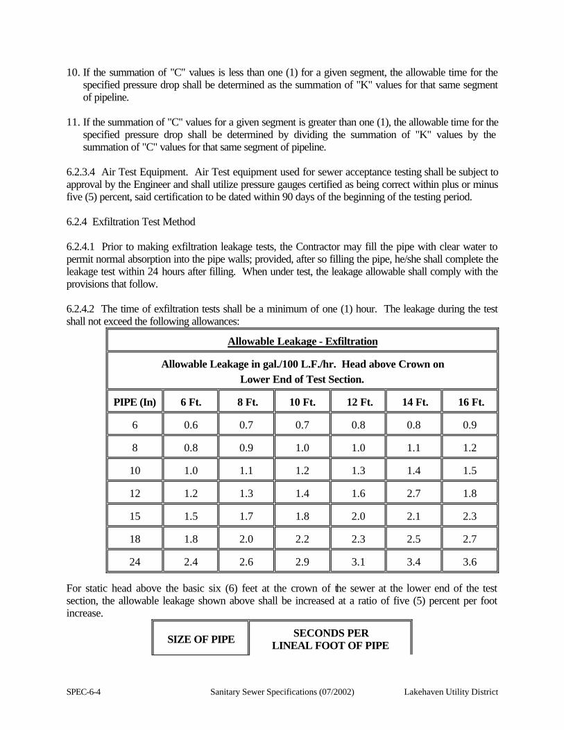
SPEC-6-4 Sanitary Sewer Specifications (07/2002) Lakehaven Utility District
10. If the summation of "C" values is less than one (1) for a given segment, the allowable time for the specified pressure drop shall be determined as the summation of "K" values for that same segment of pipeline.
11. If the summation of "C" values for a given segment is greater than one (1), the allowable time for the
specified pressure drop shall be determined by dividing the summation of "K" values by the summation of "C" values for that same segment of pipeline.
6.2.3.4 Air Test Equipment. Air Test equipment used for sewer acceptance testing shall be subject to approval by the Engineer and shall utilize pressure gauges certified as being correct within plus or minus five (5) percent, said certification to be dated within 90 days of the beginning of the testing period. 6.2.4 Exfiltration Test Method 6.2.4.1 Prior to making exfiltration leakage tests, the Contractor may fill the pipe with clear water to permit normal absorption into the pipe walls; provided, after so filling the pipe, he/she shall complete the leakage test within 24 hours after filling. When under test, the leakage allowable shall comply with the provisions that follow. 6.2.4.2 The time of exfiltration tests shall be a minimum of one (1) hour. The leakage during the test shall not exceed the following allowances:
Allowable Leakage - Exfiltration
Allowable Leakage in gal./100 L.F./hr. Head above Crown on
Lower End of Test Section. PIPE (In)
6 Ft.
8 Ft.
10 Ft.
12 Ft.
14 Ft.
16 Ft.
6
0.6
0.7
0.7
0.8
0.8
0.9
8
0.8
0.9
1.0
1.0
1.1
1.2
10
1.0
1.1
1.2
1.3
1.4
1.5
12
1.2
1.3
1.4
1.6
2.7
1.8
15
1.5
1.7
1.8
2.0
2.1
2.3
18
1.8
2.0
2.2
2.3
2.5
2.7
24
2.4
2.6
2.9
3.1
3.4
3.6
For static head above the basic six (6) feet at the crown of the sewer at the lower end of the test section, the allowable leakage shown above shall be increased at a ratio of five (5) percent per foot increase.
SIZE OF PIPE
SECONDS PER
LINEAL FOOT OF PIPE
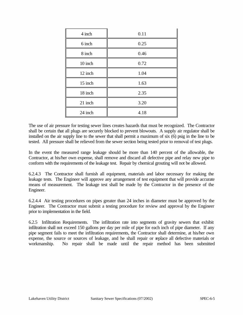
Lakehaven Utility District Sanitary Sewer Specifications (07/2002) SPEC-6-5
4 inch
0.11
6 inch
0.25
8 inch
0.46
10 inch
0.72
12 inch
1.04
15 inch
1.63
18 inch
2.35
21 inch
3.20
24 inch
4.18
The use of air pressure for testing sewer lines creates hazards that must be recognized. The Contractor shall be certain that all plugs are securely blocked to prevent blowouts. A supply air regulator shall be installed on the air supply line to the sewer that shall permit a maximum of six (6) psig in the line to be tested. All pressure shall be relieved from the sewer section being tested prior to removal of test plugs. In the event the measured range leakage should be more than 140 percent of the allowable, the Contractor, at his/her own expense, shall remove and discard all defective pipe and relay new pipe to conform with the requirements of the leakage test. Repair by chemical grouting will not be allowed. 6.2.4.3 The Contractor shall furnish all equipment, materials and labor necessary for making the leakage tests. The Engineer will approve any arrangement of test equipment that will provide accurate means of measurement. The leakage test shall be made by the Contractor in the presence of the Engineer. 6.2.4.4 Air testing procedures on pipes greater than 24 inches in diameter must be approved by the Engineer. The Contractor must submit a testing procedure for review and approval by the Engineer prior to implementation in the field. 6.2.5 Infiltration Requirements. The infiltration rate into segments of gravity sewers that exhibit infiltration shall not exceed 150 gallons per day per mile of pipe for each inch of pipe diameter. If any pipe segment fails to meet the infiltration requirements, the Contractor shall determine, at his/her own expense, the source or sources of leakage, and he shall repair or replace all defective materials or workmanship. No repair shall be made until the repair method has been submitted
SPEC-6-6 Sanitary Sewer Specifications (07/2002) Lakehaven Utility District
to and approved by the Engineer. The completed pipe installation shall meet the infiltration requirements before being considered acceptable. 6.2.6 Test Compliance. If the pipe installation fails to meet specified test requirements, the Contractor shall determine, at the Contractor's expense, the source or sources of leakage, and he/she shall repair or replace all defective materials or workmanship. No repair shall be made until the repair method has been submitted to and approved by the Engineer. The completed pipe installation shall meet the requirements of the test method used before being considered acceptable. 6.3 TESTING OF PRESSURE PIPELINES 6.3.1 Testing of all pipelines, which under normal operating conditions will be subjected to hydraulic pressure, shall be hydraulically tested at the greater of 150 percent of the working pressure or 100 psi hydrostatic pressure. Any leaks that develop shall be eliminated. Pipelines shall be cleaned and flushed before testing. Drop-piping for force mains shall be pressure tested. 6.3.2 The method of testing shall be in accordance with Section 13 of AWWA Standard Specifications for installation of cast iron water mains. All gauges, meters and taps shall be furnished by the Contractor. 6.3.3 Leakage shall not exceed 1/4 of the volume allowed by the formula specified in Section 13.7 of AWWA Standard Specifications C-600. 6.3.4 Water used for testing pressure pipelines shall be furnished, disposed of and paid for by the Contractor. 6.4 TESTING OF MANHOLES 6.4.1 Vacuum Test 6.4.1.1 The Contractor shall be fully familiar with the vacuum testing equipment that he/she proposes to use. In addition, the Contractor shall provide a minimum of 4 hours of instruction by a factory-authorized representative at the outset of the work. The vacuum test shall be performed prior to backfilling the manhole. The boot clamps shall be properly tightened to prevent the boot from being sucked into the manhole. Proper bracing of stub ends is required. 6.4.1.2 Testing of all manholes shall be in accordance the following: 1. Initial pressure test - 10 inches Hg (i.e. 20 inches Hg absolute)
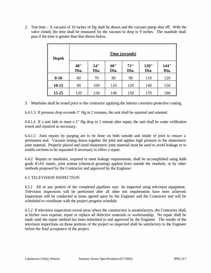
Lakehaven Utility District Sanitary Sewer Specifications (07/2002) SPEC-6-7
2. Test time - A vacuum of 10 inches of Hg shall be drawn and the vacuum pump shut off. With the valve closed, the time shall be measured for the vacuum to drop to 9 inches. The manhole shall pass if the time is greater than that shown below.
Depth
Time (seconds)
48" Dia.
54" Dia.
60" Dia.
72" Dia.
120" Dia.
144" Dia.
0-10
60
70
80
90
110
120
10-15
90
100
110
120
140
150
15-25
120
130
140
150
170
180
3. Manholes shall be tested prior to the contractor applying the interior corrosion protective coating. 6.4.1.3 If pressure drop exceeds 1" Hg in 2 minutes, the unit shall be repaired and retested. 6.4.1.4 If a unit fails to meet a 1" Hg drop in 1 minute after repair, the unit shall be water exfiltration tested and repaired as necessary. 6.4.1.5 Joint repairs by parging are to be done on both outside and inside of joint to ensure a permanent seal. Vacuum testing draws together the joint and applies high pressure to the elastomeric joint material. Properly placed and sized elastomeric joint material must be used to avoid leakage or to enable sections to be separated if necessary to effect a repair. 6.4.2 Repairs to manholes, required to meet leakage requirements, shall be accomplished using knife grade IGAS mastic, joint sealant (chemical grouting) applied from outside the manhole, or by other methods proposed by the Contractor and approved by the Engineer. 6.5 TELEVISION INSPECTION 6.5.1 All or any portion of the completed pipelines may be inspected using television equipment. Television inspections will be performed after all other test requirements have been achieved. Inspections will be conducted at times agreed upon by the Engineer and the Contractor and will be scheduled to coordinate with the project progress schedule. 6.5.2 If television inspections reveal areas where the construction is unsatisfactory, the Contractor shall, at his/her own expense, repair or replace all defective materials or workmanship. No repair shall be made until the repair method has been submitted to and approved by the Engineer. The results of the television inspections on those portions of the project so inspected shall be satisfactory to the Engineer before the final acceptance of the project.
SPEC-6-8 Sanitary Sewer Specifications (07/2002) Lakehaven Utility District
6.5.3 If the Contractor requests a television inspection and the inspection reveals construction deficiencies that must be corrected, the cost of re-inspection by television will be charged to the Contractor. Payment will be made by deduction from the Contractor's payments. 6.5.4 The District will provide all the equipment and labor and will pay all costs of performing the initial television inspection, except for that stated in 6.5.3. If a re-inspection is necessary, all work necessary to perform the re-inspection shall be accomplished at the Contractor's expense.
Lakehaven Utility District Sanitary Sewer Specifications (07/2002) SPEC-7-1
SECTION 7
RESTORATION 7.1 GENERAL This section includes provisions for the restoration of the various surfaces, which will or may be encountered during construction of a project. All surfaces disturbed in the process of executing a contract shall be restored as near as physically possible to those conditions existing prior to commencement of work, or better. For clearing of sod and other plant material and removal of pavement, refer to Section 1 of these specifications. 7.2 TEMPORARY SURFACING AND MAINTENANCE The Contractor shall provide temporary surfacing for trenches in roadways that will carry traffic before the pavement is restored. Temporary surfacing shall consist of installing crushed surfacing top course material to the elevation of the top of the adjacent pavement. Crushed surfacing top course material and installation shall be as specified in Section 7.3.5 of the specifications herein. The Contractor shall be responsible for maintaining that temporary surfacing in a safe and passable condition and for dust control as specified in the Special Provisions of the Contract and as required by the Engineer. 7.2.1 Temporary Pavement Patching During construction of the sewer system, the Contractor shall complete the trench backfill through intersections, as specified elsewhere within the Special Provisions, to within 0.2 of a foot below the existing pavement surface. The area(s) shall then be patched with asphalt cold-mix or asphalt concrete pavement approved by the Engineer. The Contractor shall maintain the temporary patch until such time as the pavement is restored, as defined in these specifications. The Contractor shall have adequate patching material available to insure the patch will be completed before the end of a work shift. After the sewer pipe has been accepted, or when directed by the Engineer, the patched area(s) shall be excavated and prepared for pavement restoration. The pavement restoration shall be completed within the same day the temporary patch is removed. "Temporary Pavement Patching" shall be used only when directed by the Engineer and for the convenience of the traveling public. 7.2.2 Dust Control. The Contractor shall provide water and/or a dust palliative and apply, as ordered by the Engineer, for the alleviation or prevention of dust nuisances. A water truck shall be assigned to the Project for full-time use; all costs of which shall be merged in the various lump sum and unit prices bid. Should the Contractor elect to utilize gravel, or any bituminous
SPEC-7-2 Sanitary Sewer Specifications (07/2002) Lakehaven Utility District
product, as a means of providing and/or maintaining dust control, it shall be at his/her expense. Rock and bituminous products, as shown in the proposal, are intended to be utilized for roadway restoration, not for dust control. 7.3 PAVEMENT RESTORATION 7.3.1 All street, roadway and driveway surfacing that is removed or damaged by the Contractor's operations shall be restored by repairing or replacing the surfacing as specified herein. Unless otherwise noted in these Specifications, on the Contract Drawings, or as directed by the Engineer, bituminous, asphalt and cement concrete pavement shall be restored using the same type of material as the existing pavement, and the existing surfacing on unimproved public streets and roadways shall be replaced with gravel surfacing as specified herein. Minimum pavement thickness (net after compaction) shall be established by the agency having jurisdiction. Where such agency does not specify minimum thickness, the minimum thickness shall be two (2) inches, net after compaction. Other roadway surfaces shall be restored in a manner approved by the Engineer, using the same type of material as the existing surfacing. Particular care shall be taken to minimize damage to pavement adjacent to construction areas. During pavement restoration and after gravel base has been placed and unsuitable material removed, if subgrade surfaces are not suitable due to wet conditions or existing materials, the Contractor shall at his expense remove all unsuitable materials and fill with Gravel Base, Class B, to provide a firm and stable base just prior to placement of crushed stone and asphalt. 7.3.2 Unless otherwise noted, all valve boxes, manhole frames, catch basin gratings and other utility appurtenances located within paved areas shall be set or raised to finish grade. Utility appurtenances located in asphalt concrete pavement shall be raised to finish grade after the surfacing is completed. Cutouts shall be concentric with the appurtenance and the patch shall be as specified in Sections 7.3.4, 7.3.5, and 7.3.6 of the specifications herein. Pavement restoration details are shown on the Contract Drawings. 7.3.3 Construction surveying and staking are the responsibility of the Contractor. 7.3.4 Gravel Base 7.3.4.1 Gravel base shall consist of naturally occurring or screened gravel. It shall be essentially free from various types of wood waste or other extraneous or objectionable materials. It shall have such characteristics of size and shape that it will compact readily and shall meet the following test requirements:
Stabilometer "R" Value . . . . . . . . . 72 min. Swell pressure . . . . . . . . . . . . . . 0.3 psi max.
The maximum particle size shall not exceed 2/3 of the depth of the layer being placed.
Lakehaven Utility District Sanitary Sewer Specifications (07/2002) SPEC-7-3
Gravel base shall meet the following requirements for gradation and quality when placed in hauling vehicles for delivery to the roadway or during manufacture and placement into a temporary stockpile. The Engineer will determine the exact point of acceptance.
% Passing 1/4" square opening
25 min.
% Passing No. 200 sieve
10.0 max.
All percentages are by weight.
Dust Ratio: % Passing U.S. No. 200
% Passing No. 40 Sieve
2/3 max.
% Sand Equivalent
30 min.
Gravel base material retained on a 1/4 inch square sieve shall contain not more than 0.20 percent by weight of wood waste. 7.3.4.2 Before placement of gravel base, all depressions shall be drained and filled and the fill shall be compacted as specified for trench backfill. The entire subgrade shall then be shaped to a smooth, uniform surface, reasonably true to line, grade and cross-section as approved by the Engineer. 7.3.4.3 Placement of Gravel Base 7.3.4.3.1 All equipment necessary for the satisfactory performance of this construction shall be on the project and approved by the Engineer prior to beginning work. If central mix plant methods are used, the central mixing plant shall comply with the following requirements: The cold aggregate feeder shall be mechanically operated and adjustable to the extent necessary to provide a uniform and continuous flow of materials. These materials shall be deposited in an approved mixer, with a sufficient amount of water being added to obtain the required density when spread and compacted. The water shall be weighed or metered and dispensed through a device providing uniform dispersion across the mixer. The mixing plant shall be provided with weighting or calibrating devices, feeders, provisions for sampling and other devices and equipment so designed, coordinated, and operated as to produce a uniform mixture and to permit the sampling of the materials before and after mixing. The mixer shall be kept in good condition and mixing blades or paddles shall be of proper size, adjustment, and clearance to provide positive and uniform mixing of the entire components of the mixture at all times. The capacity of the plant and equipment furnished on the work shall be adequate at all times to provide for efficient and continuous operations insofar as practicable.
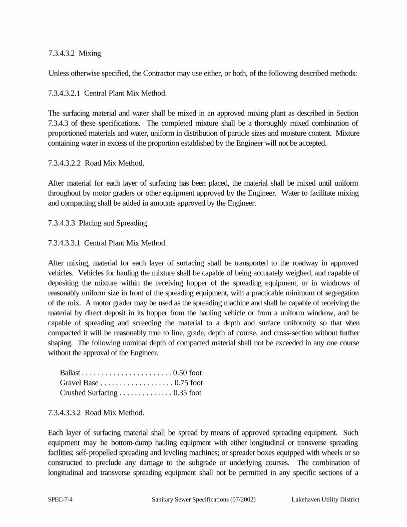
SPEC-7-4 Sanitary Sewer Specifications (07/2002) Lakehaven Utility District
7.3.4.3.2 Mixing Unless otherwise specified, the Contractor may use either, or both, of the following described methods:
7.3.4.3.2.1 Central Plant Mix Method. The surfacing material and water shall be mixed in an approved mixing plant as described in Section 7.3.4.3 of these specifications. The completed mixture shall be a thoroughly mixed combination of proportioned materials and water, uniform in distribution of particle sizes and moisture content. Mixture containing water in excess of the proportion established by the Engineer will not be accepted. 7.3.4.3.2.2 Road Mix Method. After material for each layer of surfacing has been placed, the material shall be mixed until uniform throughout by motor graders or other equipment approved by the Engineer. Water to facilitate mixing and compacting shall be added in amounts approved by the Engineer. 7.3.4.3.3 Placing and Spreading 7.3.4.3.3.1 Central Plant Mix Method. After mixing, material for each layer of surfacing shall be transported to the roadway in approved vehicles. Vehicles for hauling the mixture shall be capable of being accurately weighed, and capable of depositing the mixture within the receiving hopper of the spreading equipment, or in windrows of reasonably uniform size in front of the spreading equipment, with a practicable minimum of segregation of the mix. A motor grader may be used as the spreading machine and shall be capable of receiving the material by direct deposit in its hopper from the hauling vehicle or from a uniform windrow, and be capable of spreading and screeding the material to a depth and surface uniformity so that when compacted it will be reasonably true to line, grade, depth of course, and cross-section without further shaping. The following nominal depth of compacted material shall not be exceeded in any one course without the approval of the Engineer.
Ballast . . . . . . . . . . . . . . . . . . . . . . . 0.50 foot Gravel Base . . . . . . . . . . . . . . . . . . . 0.75 foot Crushed Surfacing . . . . . . . . . . . . . . 0.35 foot
7.3.4.3.3.2 Road Mix Method. Each layer of surfacing material shall be spread by means of approved spreading equipment. Such equipment may be bottom-dump hauling equipment with either longitudinal or transverse spreading facilities; self-propelled spreading and leveling machines; or spreader boxes equipped with wheels or so constructed to preclude any damage to the subgrade or underlying courses. The combination of longitudinal and transverse spreading equipment shall not be permitted in any specific sections of a
Lakehaven Utility District Sanitary Sewer Specifications (07/2002) SPEC-7-5
project. The Engineer will determine the limits of a specific section. Spreading on small areas of less than 2,000 square yards or on areas irregular in shape may be accomplished by other means as approved by the Engineer. The depth of material in any course shall be as specified in Section 7.3.4.3.3.1 herein. 7.3.4.3.4 Shaping and Compaction Except as provided in Section 7.3.4.3.3.1, final shaping of each layer prior to compaction shall be accomplished by approved equipment. Immediately following spreading and final shaping, each layer of surfacing shall be compacted to at least 95 percent of the standard density determined by WSDOT Test Method No. 606 before the next succeeding layer of surfacing or pavement is placed thereon. The determination of field in-place density shall be made by the Nuclear gauge or the Washington Densometer. When the thickness of surfacing is less than 0.15 foot, density testing will not be required and the Engineer will determine the number of coverages required for the particular compaction equipment available. Vibratory compactors and rollers shall be adequate in design and number to provide compaction and obtain the specified density for each layer while still moist. A mist spray of water shall be applied as needed to replace moisture lost by evaporation. The completed layer shall have a smooth, tight, uniform surface, reasonably true to the line, grade, and cross-section shown in the plans, or as staked by the Engineer. 7.3.4.3.5 Miscellaneous Requirements The surface of each layer of surfacing material shall be maintained reasonably true to line, grade and cross-section by blading, watering and rolling until placing the next succeeding course. The first course of surfacing material shall be placed on all available subgrade before placing the succeeding course, unless otherwise authorized by the Engineer. Unless otherwise approved, there shall be a distance of not less than one (1) station between the construction of any two (2) courses of surfacing or ballast. When keystone is required, it shall be placed in accordance with Section 7.3.4.3.5.1 before terminating each day's operation. Should irregularities develop in any surface during or after compaction, they shall be remedied by loosening the surface and correcting the defects, after which the entire area, including the surrounding surface, shall be thoroughly recompacted. Any additional materials necessary to make the repairs shall be furnished by the Contractor at the unit contract price. 7.3.4.3.5.1 Keystone When necessary, as determined by the Engineer, crushed surfacing top course shall be used for keystone to key the top surface of ballast, gravel base, crushed surfacing base course or any other surfacing course which requires keying. The keystone shall be spread evenly on top of the surfacing course requiring it, in the amount ordered by the Engineer, by means of approved spreading equipment. The surface shall be watered and, if necessary, bladed lightly until the keystone is worked into the interstices of the surfacing course, without excessive displacement, and shall be compacted. The operations of adding keystone, wetting, blading and compacting shall be continued until the course has become thoroughly keyed and compacted.
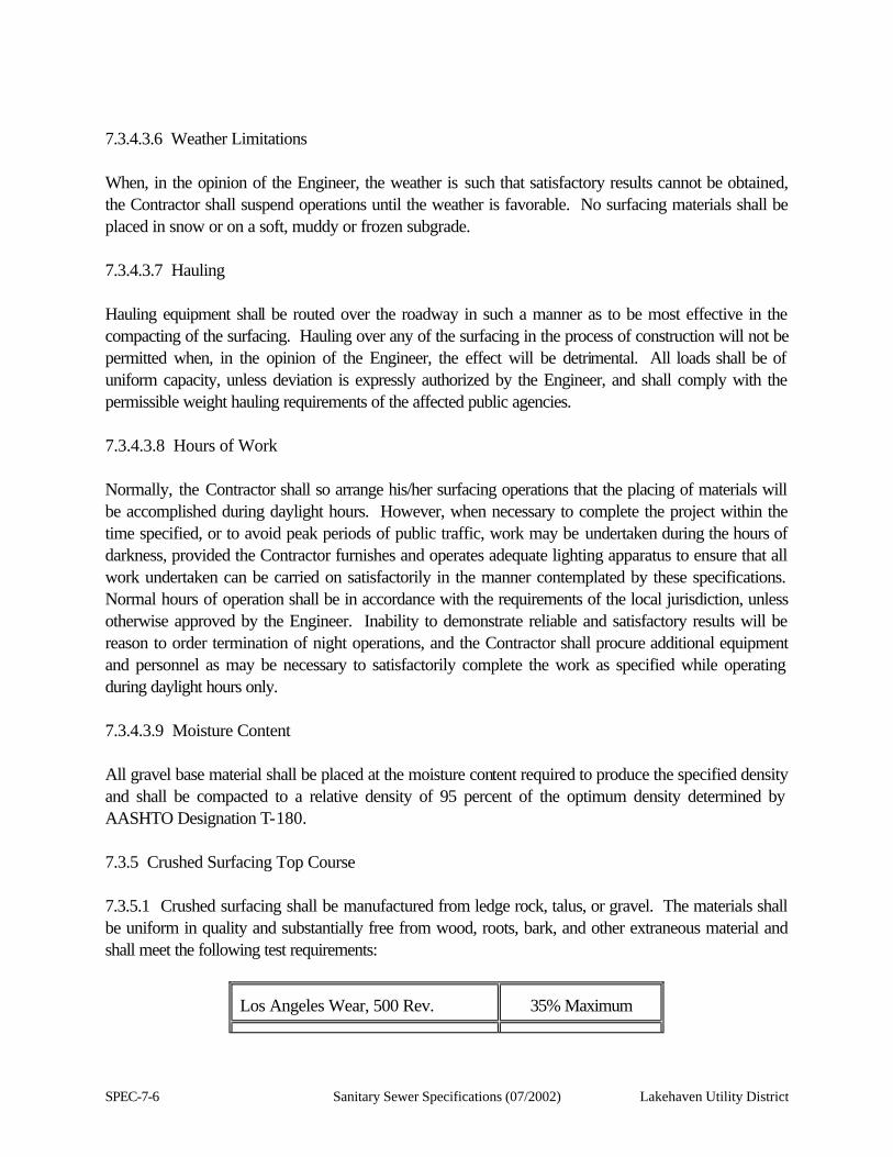
SPEC-7-6 Sanitary Sewer Specifications (07/2002) Lakehaven Utility District
7.3.4.3.6 Weather Limitations When, in the opinion of the Engineer, the weather is such that satisfactory results cannot be obtained, the Contractor shall suspend operations until the weather is favorable. No surfacing materials shall be placed in snow or on a soft, muddy or frozen subgrade. 7.3.4.3.7 Hauling Hauling equipment shall be routed over the roadway in such a manner as to be most effective in the compacting of the surfacing. Hauling over any of the surfacing in the process of construction will not be permitted when, in the opinion of the Engineer, the effect will be detrimental. All loads shall be of uniform capacity, unless deviation is expressly authorized by the Engineer, and shall comply with the permissible weight hauling requirements of the affected public agencies. 7.3.4.3.8 Hours of Work Normally, the Contractor shall so arrange his/her surfacing operations that the placing of materials will be accomplished during daylight hours. However, when necessary to complete the project within the time specified, or to avoid peak periods of public traffic, work may be undertaken during the hours of darkness, provided the Contractor furnishes and operates adequate lighting apparatus to ensure that all work undertaken can be carried on satisfactorily in the manner contemplated by these specifications. Normal hours of operation shall be in accordance with the requirements of the local jurisdiction, unless otherwise approved by the Engineer. Inability to demonstrate reliable and satisfactory results will be reason to order termination of night operations, and the Contractor shall procure additional equipment and personnel as may be necessary to satisfactorily complete the work as specified while operating during daylight hours only. 7.3.4.3.9 Moisture Content All gravel base material shall be placed at the moisture content required to produce the specified density and shall be compacted to a relative density of 95 percent of the optimum density determined by AASHTO Designation T-180. 7.3.5 Crushed Surfacing Top Course 7.3.5.1 Crushed surfacing shall be manufactured from ledge rock, talus, or gravel. The materials shall be uniform in quality and substantially free from wood, roots, bark, and other extraneous material and shall meet the following test requirements:
Los Angeles Wear, 500 Rev.
35% Maximum
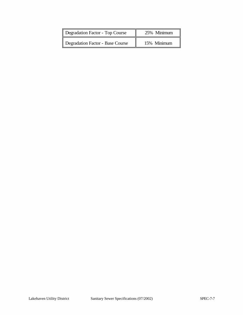
Lakehaven Utility District Sanitary Sewer Specifications (07/2002) SPEC-7-7
Degradation Factor - Top Course 25% Minimum Degradation Factor - Base Course
15% Minimum
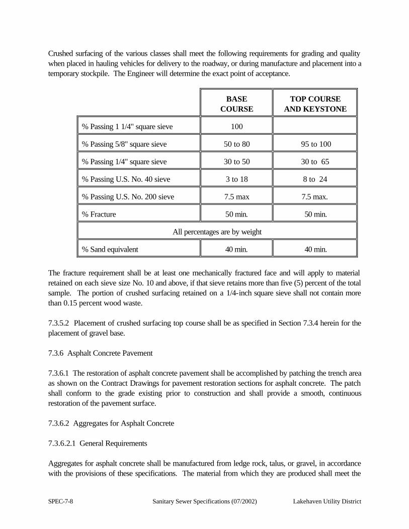
SPEC-7-8 Sanitary Sewer Specifications (07/2002) Lakehaven Utility District
Crushed surfacing of the various classes shall meet the following requirements for grading and quality when placed in hauling vehicles for delivery to the roadway, or during manufacture and placement into a temporary stockpile. The Engineer will determine the exact point of acceptance.
BASE
COURSE
TOP COURSE
AND KEYSTONE % Passing 1 1/4" square sieve
100
% Passing 5/8" square sieve
50 to 80
95 to 100
% Passing 1/4" square sieve
30 to 50
30 to 65
% Passing U.S. No. 40 sieve
3 to 18
8 to 24
% Passing U.S. No. 200 sieve
7.5 max
7.5 max.
% Fracture
50 min.
50 min.
All percentages are by weight
% Sand equivalent
40 min.
40 min.
The fracture requirement shall be at least one mechanically fractured face and will apply to material retained on each sieve size No. 10 and above, if that sieve retains more than five (5) percent of the total sample. The portion of crushed surfacing retained on a 1/4-inch square sieve shall not contain more than 0.15 percent wood waste. 7.3.5.2 Placement of crushed surfacing top course shall be as specified in Section 7.3.4 herein for the placement of gravel base. 7.3.6 Asphalt Concrete Pavement 7.3.6.1 The restoration of asphalt concrete pavement shall be accomplished by patching the trench area as shown on the Contract Drawings for pavement restoration sections for asphalt concrete. The patch shall conform to the grade existing prior to construction and shall provide a smooth, continuous restoration of the pavement surface. 7.3.6.2 Aggregates for Asphalt Concrete 7.3.6.2.1 General Requirements Aggregates for asphalt concrete shall be manufactured from ledge rock, talus, or gravel, in accordance with the provisions of these specifications. The material from which they are produced shall meet the
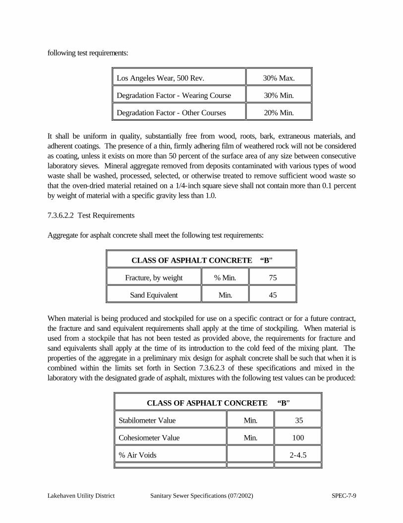
Lakehaven Utility District Sanitary Sewer Specifications (07/2002) SPEC-7-9
following test requirements:
Los Angeles Wear, 500 Rev.
30% Max.
Degradation Factor - Wearing Course
30% Min.
Degradation Factor - Other Courses
20% Min.
It shall be uniform in quality, substantially free from wood, roots, bark, extraneous materials, and adherent coatings. The presence of a thin, firmly adhering film of weathered rock will not be considered as coating, unless it exists on more than 50 percent of the surface area of any size between consecutive laboratory sieves. Mineral aggregate removed from deposits contaminated with various types of wood waste shall be washed, processed, selected, or otherwise treated to remove sufficient wood waste so that the oven-dried material retained on a 1/4-inch square sieve shall not contain more than 0.1 percent by weight of material with a specific gravity less than 1.0. 7.3.6.2.2 Test Requirements Aggregate for asphalt concrete shall meet the following test requirements:
CLASS OF ASPHALT CONCRETE “B”
Fracture, by weight
% Min.
75
Sand Equivalent
Min.
45
When material is being produced and stockpiled for use on a specific contract or for a future contract, the fracture and sand equivalent requirements shall apply at the time of stockpiling. When material is used from a stockpile that has not been tested as provided above, the requirements for fracture and sand equivalents shall apply at the time of its introduction to the cold feed of the mixing plant. The properties of the aggregate in a preliminary mix design for asphalt concrete shall be such that when it is combined within the limits set forth in Section 7.3.6.2.3 of these specifications and mixed in the laboratory with the designated grade of asphalt, mixtures with the following test values can be produced:
CLASS OF ASPHALT CONCRETE “B”
Stabilometer Value
Min.
35
Cohesiometer Value
Min.
100
% Air Voids
2-4.5
SPEC-7-10 Sanitary Sewer Specifications (07/2002) Lakehaven Utility District
Modified Lottman Stripping Test Pass
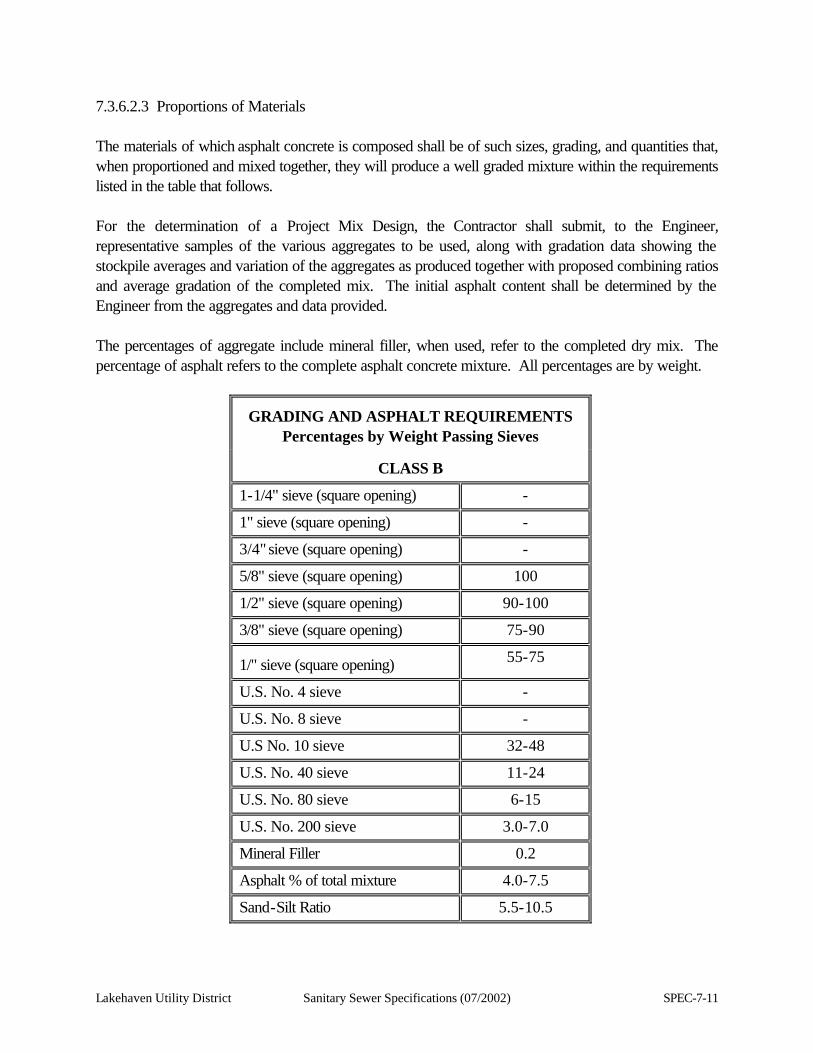
Lakehaven Utility District Sanitary Sewer Specifications (07/2002) SPEC-7-11
7.3.6.2.3 Proportions of Materials The materials of which asphalt concrete is composed shall be of such sizes, grading, and quantities that, when proportioned and mixed together, they will produce a well graded mixture within the requirements listed in the table that follows. For the determination of a Project Mix Design, the Contractor shall submit, to the Engineer, representative samples of the various aggregates to be used, along with gradation data showing the stockpile averages and variation of the aggregates as produced together with proposed combining ratios and average gradation of the completed mix. The initial asphalt content shall be determined by the Engineer from the aggregates and data provided. The percentages of aggregate include mineral filler, when used, refer to the completed dry mix. The percentage of asphalt refers to the complete asphalt concrete mixture. All percentages are by weight.
GRADING AND ASPHALT REQUIREMENTS
Percentages by Weight Passing Sieves
CLASS B
1-1/4" sieve (square opening) -
1" sieve (square opening) -
3/4" sieve (square opening) -
5/8" sieve (square opening) 100
1/2" sieve (square opening) 90-100
3/8" sieve (square opening) 75-90 1/" sieve (square opening) 55-75
U.S. No. 4 sieve -
U.S. No. 8 sieve -
U.S No. 10 sieve 32-48
U.S. No. 40 sieve 11-24
U.S. No. 80 sieve 6-15
U.S. No. 200 sieve 3.0-7.0
Mineral Filler 0.2
Asphalt % of total mixture 4.0-7.5
Sand-Silt Ratio 5.5-10.5
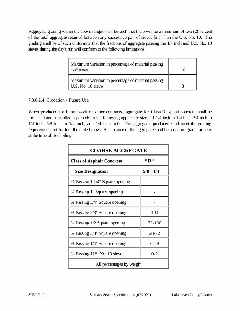
SPEC-7-12 Sanitary Sewer Specifications (07/2002) Lakehaven Utility District
Aggregate grading within the above ranges shall be such that there will be a minimum of two (2) percent of the total aggregate retained between any successive pair of sieves finer than the U.S. No. 10. The grading shall be of such uniformity that the fractions of aggregate passing the 1/4 inch and U.S. No. 10 sieves during the day's run will conform to the following limitations:
Maximum variation in percentage of material passing 1/4" sieve
10 Maximum variation in percentage of material passing U.S. No. 10 sieve
8
7.3.6.2.4 Gradation - Future Use When produced for future work on other contracts, aggregate for Class B asphalt concrete, shall be furnished and stockpiled separately in the following applicable sizes: 1 1/4 inch to 1/4 inch, 3/4 inch to 1/4 inch, 5/8 inch to 1/4 inch, and 1/4 inch to 0. The aggregates produced shall meet the grading requirements set forth in the table below. Acceptance of the aggregate shall be based on gradation tests at the time of stockpiling.
COARSE AGGREGATE
Class of Asphalt Concrete “ B “
Size Designation 5/8"-1/4" % Passing 1 1/4" Square opening
-
% Passing 1" Square opening
-
% Passing 3/4" Square opening
-
% Passing 5/8" Square opening
100
% Passing 1/2 Square opening
72-100
% Passing 3/8" Square opening
28-72
% Passing 1/4" Square opening
0-28
% Passing U.S. No. 10 sieve
0-2
All percentages by weight
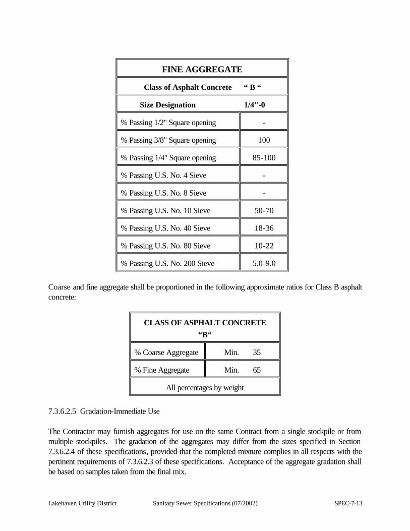
Lakehaven Utility District Sanitary Sewer Specifications (07/2002) SPEC-7-13
FINE AGGREGATE
Class of Asphalt Concrete “ B “
Size Designation 1/4"-0 % Passing 1/2" Square opening
-
% Passing 3/8" Square opening
100
% Passing 1/4" Square opening
85-100
% Passing U.S. No. 4 Sieve
-
% Passing U.S. No. 8 Sieve
-
% Passing U.S. No. 10 Sieve
50-70
% Passing U.S. No. 40 Sieve
18-36
% Passing U.S. No. 80 Sieve
10-22
% Passing U.S. No. 200 Sieve
5.0-9.0
Coarse and fine aggregate shall be proportioned in the following approximate ratios for Class B asphalt concrete:
CLASS OF ASPHALT CONCRETE
“B“ % Coarse Aggregate
Min. 35
% Fine Aggregate
Min. 65
All percentages by weight
7.3.6.2.5 Gradation-Immediate Use The Contractor may furnish aggregates for use on the same Contract from a single stockpile or from multiple stockpiles. The gradation of the aggregates may differ from the sizes specified in Section 7.3.6.2.4 of these specifications, provided that the completed mixture complies in all respects with the pertinent requirements of 7.3.6.2.3 of these specifications. Acceptance of the aggregate gradation shall be based on samples taken from the final mix.

SPEC-7-14 Sanitary Sewer Specifications (07/2002) Lakehaven Utility District
Lakehaven Utility District Sanitary Sewer Specifications (07/2002) SPEC-7-15
7.3.6.2.6 Blending Sand In the production of mineral aggregate for asphalt concrete there is often a deficiency of material passing the U.S. No. 40 sieve. When this occurs, blending sand in an amount specified by the Engineer may be used to make up this deficiency; provided, however, that a satisfactory final mix is produced, including fracture requirements. Blending sand shall be clean, hard, sound material, either naturally occurring sand or crusher fines, and must be material which will readily accept an asphalt coating. The exact grading requirements for the blending sand shall be such that, when it is mixed with a mineral aggregate, the combined product shall meet the requirements of Section 7.3.6.2.3 of these specifications for the class of material involved. Blending sand shall meet the following requirement:
Sand Equivalent 30 % Minimum Blending sand shall be tested by an independent testing laboratory at the Contractor's expense and submitted to the Engineer for approval prior to use. 7.3.6.2.7 Mineral Filler Mineral filler shall conform to the requirements of AASHTO Designation M17. 7.3.6.3 Asphalt Pavement Construction 7.3.6.3.1 Asphalt Pavers Asphalt pavers shall be self-contained, power-propelled units, provided with an activated screed or strike-off assembly, heated if necessary, and capable of spreading and finishing courses of asphalt plant mix material in lane widths applicable to the specified typical section and thickness' shown in the Contract Drawings. The screed or strike-off assembly shall effectively produce a finished surface of the required evenness and texture, without tearing, shoving or gouging the mixture. Any extensions placed on the paver shall have the same equipment as the rest of the paver. When laying mixtures, the paver shall be operated at a uniform forward speed, consistent with the plant production rate and roller train capacity, to result in a nearly continuous operation. The auger speed and flight gate opening shall be adjusted to coordinate with the operation. The paver shall be equipped with automatic screed controls with sensors for either or both sides of the paver, capable of sensing grade from an outside reference line, sensing the transverse slope of the screed, and providing the automatic signals which operate the screed to maintain the desired grade and transverse slope. The sensor shall be so constructed that it will operate from a reference line or a multi-footed ski-like arrangement.
SPEC-7-16 Sanitary Sewer Specifications (07/2002) Lakehaven Utility District
The transverse slope controller shall be capable of maintaining the screed at the desired slope within plus or minus 0.1 percent. The paver shall be equipped with automatic feeder controls, properly adjusted to maintain a uniform depth of material ahead of the screed. Manual operation will be permitted in the construction of irregularly shaped and minor areas. When specified in the contract, reference lines will be required for both outer edges of the traveled way for each main line roadway for vertical control. Horizontal control utilizing the reference line will be permitted. The grade and slope for intermediate lanes shall be controlled automatically from reference lines or by means of a multi-footed ski and a slope control device. When the finish of the grade prepared for paving is superior to the established tolerances, and, when in the opinion of the Engineer, further improvement to the line, grade, cross-section and smoothness can best be achieved without the use of the reference line, a multi-footed ski-like arrangement may be substituted subject to the continued approval of the Engineer. After paving the first lane, a joint matcher may be used, subject to the approval of the Engineer. The use of the reference line shall be reinstituted immediately whenever the Contractor fails to maintain a superior pavement, rhythmic undulations occur, or the surface smoothness of the course being paved fails to meet the requirements for wearing course. The reference line may be removed after the completion of the first course of asphalt concrete, when approved by the Engineer and subject to reinstallation at the Contractor's expense. The Contractor shall furnish and install all pins, brackets, tensioning devices, wire and accessories necessary for satisfactory operation of the automatic control equipment. The Contractor shall submit samples of the above items with his methods and procedures to the Engineer for approval prior to installation. 7.3.6.3.2 Rollers Rollers shall be of the steel wheel, vibratory, or pneumatic tire type, in good condition, capable of reversing without backlash, and shall be operated at speeds slow enough to avoid displacement of the mixture. The number and weight of rollers shall be sufficient to compact the mixture as required in Section 7.3.6.3.11. The use of equipment which results in excessive crushing of the aggregate will not be permitted. Rollers producing pickup, washboard, uneven compaction of the surface or other undesirable results shall be rejected by the Engineer. The following specifications shall apply to the various types of rollers: 1. Vibratory Rollers
(a) A variable amplitude will be required, with at least two (2) settings.
(b) A variable frequency with a 2,000 VPM minimum.
(c) The maximum rate of travel under vibration shall be limited to three (3) MPH.
(d) Pneumatic propulsion on surface courses shall be limited to smooth tires that will not leave
Lakehaven Utility District Sanitary Sewer Specifications (07/2002) SPEC-7-17
visible tracks.
2. Pneumatic Tired Rollers
(a) The maximum rate of travel shall be limited to five (5) MPH.
(b) Skirts shall be firmly affixed to the perimeter of the roller and shall uniformly extend to within one (1) inch of the pavement surface.
3. Steel Wheel Rollers
(a) The maximum rate of travel shall be limited to four (4) MPH.
7.3.6.3.3 Conditioning of Existing Surface When the surface of the existing pavement or old base is irregular, it shall be brought to uniform grade and cross-section as directed by the Engineer. Preleveling of uneven or broken surfaces over which asphalt concrete is to be placed is required and may be accomplished by the use of an asphalt concrete of the class specified, placed with a motor patrol grader or by hand raking, as approved by the Engineer. After placement, the asphalt concrete used for preleveling shall be compacted thoroughly. Care shall be taken to insure that pre-existing drainage patterns on the existing roadway is maintained. 7.3.6.3.4 Preparation of Existing Surfaces Before construction of asphalt concrete pavement on an existing surface, all fatty asphalt patches, grease drippings, and other objectionable matter shall be entirely removed from the existing pavement. All excess asphalt joint filler shall be completely removed and all premolded joint filler shall be removed to at least 1/2-inch below the surface of the existing pavement. All types of existing pavement or bituminous surfaces shall be thoroughly cleaned, by sweeping, to remove dust and other foreign matter. A tack coat of asphalt applied at the rate of 0.02 to 0.08 gallon per square yard of retained asphalt shall be applied through the use of approved mechanical equipment to all surfaces on which any course of asphalt concrete is to be placed or abutted. The spreading equipment shall be capable of uniformly distributing asphalt materials over any area in controlled amounts and shall be equipped with hand operated spray equipment for use only on inaccessible and irregularly shaped areas. The tack coat shall be a heated cutback asphalt, or emulsified asphalt, mixing grade, as directed by the Engineer. The emulsified asphalt may be diluted with water at a rate not to exceed one (1) part water to one (1) part of emulsified asphalt, as directed by the Engineer. When asphalt concrete pavement is to be constructed over an existing paved or oiled surface, in
SPEC-7-18 Sanitary Sewer Specifications (07/2002) Lakehaven Utility District
addition to the preparation as outlined above, all holes and small depressions shall be filled with an appropriate class of asphalt concrete mix. The surface of the patched area shall be leveled and compacted thoroughly, as directed by the Engineer. 7.3.6.3.5 Heating of Asphalt Material The asphalt shall be heated to a maximum of 350 degrees Fahrenheit. The asphalt shall be heated in a manner that will avoid local overheating and provide a continuous supply of asphalt material to the mixer at a uniform temperature, plus or minus 25 degrees Fahrenheit from the temperature ordered by the Engineer. 7.3.6.3.6 Preparation of Aggregates The aggregates shall be removed from stockpile(s) in a manner to ensure a minimum of segregation when being moved to the asphalt plant for processing into the final mixture. 7.3.6.3.7 Mix Design Once the crushing operation has stabilized to the satisfaction of the Engineer, a representative sample will be obtained from the stockpiled aggregates. A sample of the stockpiled blending sand, if needed, will also be required at this time. Paving operations shall not proceed until a mix design is furnished by the Engineer. The Contractor shall allow a minimum of ten (10) working days after the necessary aggregate samples and asphalt have been received in an independent testing laboratory (at the Contractor's expense) for the preparation of a job mix design. Additional time will be required if the Contractor has requested that more than one source of asphalt cement be approved. The Contractor shall obtain the Engineer's approval prior to changing the source of asphalt cement during the production of asphalt concrete. 7.3.6.3.8 Mixing The prepared aggregates shall be combined in the mixer in the amount of each fraction of aggregates as specified or as directed by the Engineer. The asphalt material shall be measured or gauged and introduced into the mixer in the amount specified or as directed by the Engineer. After the required amounts of aggregate and asphalt material have been introduced into the mixer, unless otherwise specified, the materials shall be mixed until a complete and uniform coating of the particles and a thorough distribution of the asphalt material throughout the aggregate is secured. Wet mixing time shall be determined by the Engineer for each plant and for each type of aggregate used and shall be sufficient to produce 95 percent coated particles as determined by WSDOT Test Method No. 714. When discharged, the temperature of the mix shall not exceed 325 degrees Fahrenheit. A maximum water content of two (2) percent in the mix, at discharge, will be allowed; providing
Lakehaven Utility District Sanitary Sewer Specifications (07/2002) SPEC-7-19
the water causes no problems with handling, stripping, or flushing. In which case, the moisture content shall be reduced as directed by the Engineer. Storing or holding of the asphalt concrete mixture in approved storage facilities will be permitted during the daily operation but in no event shall the materials be held for more than 24 hours. Materials held for more than 24 hours after mixing shall be rejected and disposed of by the Contractor at no cost to the Owner. The storage facility shall have a visible device located at the top of the cone or about the third point to indicate the amount of material in storage. No material shall be accepted from the storage facility when the material in storage is below the top of the cone of the storage facility, except at the end of the working day. 7.3.6.3.9 Spreading and Finishing The mixture shall be laid upon an approved surface, spread and struck off to the grade and elevation established. Asphalt pavers complying with Section 7.3.6.3.1 shall be used to distribute the mixture. Unless otherwise directed by the Engineer or specified in the plans or in the special provisions, the nominal compacted depth of any layer of any course shall not exceed the following depth:
Asphalt Concrete Class B 0.25 foot On areas where irregularities or unavoidable obstacles make the use of mechanical spreading and finishing equipment impracticable, the paving may be done with other equipment or by hand. The internal temperature of the mixture should not be less than 185 degrees Fahrenheit upon achieving density requirements in accordance with the applicable specifications. Should the Contractor not achieve specification densities prior to 185 degrees Fahrenheit, he/she will be permitted to continue his/her compactive effort with steel wheeled rollers or a pneumatic tired roller, provided that future compaction operations are adjusted to meet the density requirements at the aforementioned temperature. The vibratory roller, in the vibratory mode, shall not be used under any circumstances whenever the internal temperature of the mixture is below 175 degrees Fahrenheit. The placing of asphalt mixtures at night will not be permitted except by approval of the Engineer or if specified in the Special Provisions. When the asphalt mixture is being produced by more than one (1) asphalt plant, the material produced by each plant shall be placed by separate spreading and compacting equipment. 7.3.6.3.10 Compaction Immediately after the asphalt concrete mixture has been spread, struck off and surface irregularities adjusted, it shall be thoroughly and uniformly compacted. The completed course shall be free from ridges, ruts, humps, depressions, objectionable marks or irregularities and in
SPEC-7-20 Sanitary Sewer Specifications (07/2002) Lakehaven Utility District
reasonable conformance with line, grade, and cross-section as shown in the plans or as established by the Engineer. If necessary, the mix design may be altered to achieve desired results. Compaction shall take place when the mixture is in the proper condition, so that no undue displacement, cracking or shoving occurs. All compaction units shall be operated at the speed, within specification limits, that will produce the required compaction. Areas inaccessible to large compaction equipment shall be compacted by mechanical or hand tampers. Any asphalt concrete that becomes loose, broken, contaminated, shows an excess or deficiency of asphalt, or is in any way defective, shall be removed and replaced, at no additional cost, with fresh hot mix, which shall be immediately compacted to conform with the surrounding area. The type of rollers to be used and their relative position in the compaction sequence shall generally be the Contractor's option, provided specification densities are attained. An exception shall be that the pneumatic tired roller shall be used between October 1 and April 1. Coverages with a vibratory or steel wheel roller may precede pneumatic tired rolling. 7.3.6.3.11 Control Nuclear gauge tests for compaction control during paving construction shall be taken at the locations determined by the Engineer and which represent lots of approximately 400 tons of mix. A minimum of five (5) randomly selected locations within the lot shall be tested. In addition to the randomly selected locations for tests of the control lot, the Engineer reserves the right to test any area which appears defective and to require further compaction of areas that fall below acceptable density readings. For Class B asphalt, where the paving is in the traffic lanes and compacted course thickness is greater than 0.10 foot, the acceptable level of compaction shall be a minimum average compacted density of 92 percent of the maximum density as determined by WSDOT Test Method 705. As a supplement to the preceding, pavement cores may be used to determine the actual in place density with the void content determined by comparison with Rice Vacuum Pycnometer density methods. Cores of the finished pavement may be substituted for nuclear gauge readings to determine densities provided the cores are taken within 48 hours of placement of the mix. If this alternate is done at the request of the Contractor, the District shall be reimbursed for the coring expenses at the rate per core specified in the Contract Provisions. Control lots not meeting the prescribed minimum density standard shall be removed and replaced with satisfactory material.
Lakehaven Utility District Sanitary Sewer Specifications (07/2002) SPEC-7-21
7.3.6.3.12 Joints The placing of the top or wearing course shall be as nearly continuous as possible and the roller shall pass over the unprotected end of the freshly laid mixture only when the laying of the course is discontinued for such length of time as to permit the mixture to become chilled. When the work is resumed, the previously compacted mixture shall be cut back to produce a slightly beveled edge for the full thickness of the course. Where a transverse joint is being made in the wearing course, strips of heavy wrapping paper shall be used. The wrapping paper shall be removed and the joint trimmed to a slightly beveled edge for the full thickness of the course prior to resumption of paving. The material which is cut away shall be wasted and new mix shall be laid against the fresh cut. Rollers or tamping irons shall be used to seal the joint. Where the asphalt concrete is to be placed against a concrete or stone curb or gutter, or against a cold pavement joint or any metal surface, a thin paint coat of emulsified asphalt shall be applied in advance of the placing. The application shall be thin and uniform, care being exercised to avoid accumulation of asphalt in depressions. The longitudinal joint in any one layer shall be offset from the layer immediately below by not more than six (6) inches nor less than two (2) inches. All longitudinal joints constructed in the top layer shall be at a lane line or edge line of traveled way. When asphalt concrete pavement is placed adjacent to cement concrete pavement, the Contractor shall construct longitudinal shoulder joints between the asphalt concrete pavement and the cement concrete pavement. The joint shall be constructed by routing or forming a longitudinal groove 1 inch deep and 1/2-inch wide in the asphalt concrete pavement and shall be filled to within 1/8-inch of flush with a mixture conforming to Section 7.3.6.3.18 of these specifications. All costs involved with constructing and filling the shoulder joints shall be incidental to and included in the unit contract price per ton for the class of asphalt being placed. 7.3.6.3.13 Samples The Engineer reserves the right to have samples cut or cored from the completed pavement or the individual courses thereof. Additionally, the Engineer may take samples of the uncompressed asphalt concrete mixtures, as well as all materials incorporated in the work. Where samples have been taken from the uncompressed asphalt concrete, new material shall be placed at a minimum of two (2) inches of compacted depth and shall conform with the surrounding areas at no additional cost to the Owner.
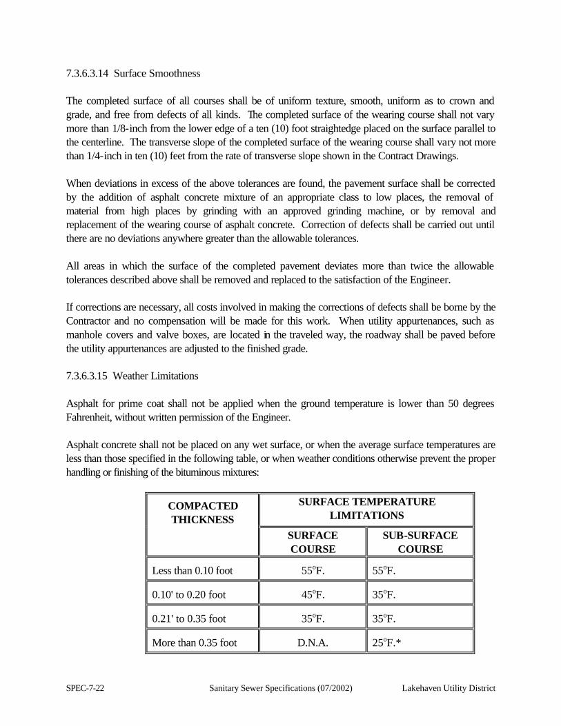
SPEC-7-22 Sanitary Sewer Specifications (07/2002) Lakehaven Utility District
7.3.6.3.14 Surface Smoothness The completed surface of all courses shall be of uniform texture, smooth, uniform as to crown and grade, and free from defects of all kinds. The completed surface of the wearing course shall not vary more than 1/8-inch from the lower edge of a ten (10) foot straightedge placed on the surface parallel to the centerline. The transverse slope of the completed surface of the wearing course shall vary not more than 1/4-inch in ten (10) feet from the rate of transverse slope shown in the Contract Drawings. When deviations in excess of the above tolerances are found, the pavement surface shall be corrected by the addition of asphalt concrete mixture of an appropriate class to low places, the removal of material from high places by grinding with an approved grinding machine, or by removal and replacement of the wearing course of asphalt concrete. Correction of defects shall be carried out until there are no deviations anywhere greater than the allowable tolerances. All areas in which the surface of the completed pavement deviates more than twice the allowable tolerances described above shall be removed and replaced to the satisfaction of the Engineer. If corrections are necessary, all costs involved in making the corrections of defects shall be borne by the Contractor and no compensation will be made for this work. When utility appurtenances, such as manhole covers and valve boxes, are located in the traveled way, the roadway shall be paved before the utility appurtenances are adjusted to the finished grade. 7.3.6.3.15 Weather Limitations Asphalt for prime coat shall not be applied when the ground temperature is lower than 50 degrees Fahrenheit, without written permission of the Engineer. Asphalt concrete shall not be placed on any wet surface, or when the average surface temperatures are less than those specified in the following table, or when weather conditions otherwise prevent the proper handling or finishing of the bituminous mixtures:
COMPACTED THICKNESS
SURFACE TEMPERATURE LIMITATIONS
SURFACE COURSE
SUB-SURFACE COURSE
Less than 0.10 foot
55oF.
55oF.
0.10' to 0.20 foot
45oF.
35oF.
0.21' to 0.35 foot
35oF.
35oF.
More than 0.35 foot
D.N.A.
25oF.*
Lakehaven Utility District Sanitary Sewer Specifications (07/2002) SPEC-7-23
*Only on dry subgrade, not frozen, and when air temperature is rising.
SPEC-7-24 Sanitary Sewer Specifications (07/2002) Lakehaven Utility District
7.3.6.3.16 Deleted. 7.3.6.3.17 Sealing of Driving Surfaces Any wearing course or other pavement course to be used for the driving surface will be evaluated by the Engineer to determine whether a fog seal is required. When the results of nuclear or core density testing show that a seal is needed, the Contractor shall apply a fog seal of CSS-1 at the rate 0.05 to 0.10 (0.03 to 0.05 residual) gallons per square yard. Unless otherwise approved by the Engineer, fog seal shall be applied prior to opening to traffic. Material used for fog seal shall be incidental to the various pavement restoration bid items. 7.3.6.3.18 Rubberized Asphalt The rubberized asphalt shall be a mixture of paving asphalt, granulated rubber, and asphalt modifier (if needed). The paving asphalt shall be AR-2000W or AR-4000W conforming to Section 7.3.6.3.20 of these specifications or AR-8000 conforming to AASHTO Specification M-226. Granulated rubber and asphalt modifier shall meet the requirements of Section 7.3.6.3.19 of these specifications. The asphalt and rubber shall be combined, as rapidly as possible, in a ratio of 80 percent asphalt to 20 percent rubber, plus or minus two (2) percent, by total weight of the combined materials. The temperature of the asphalt shall be between 350 degrees Fahrenheit and 425 degrees Fahrenheit at the time the rubber is added. This temperature shall be maintained until the consistency of the mix approaches that of a semi-fluid material as required by the Engineer. The use of up to five (5) percent asphalt modifier will be allowed. After reaching the proper consistency, application shall proceed immediately and in no case shall the material be held at temperatures greater than 350 degrees Fahrenheit for more than one (1) hour. If a job delay occurs after the mix has fully reacted, the asphalt-rubber may be allowed to cool. However, just prior to application, the asphalt-rubber mixture shall be slowly reheated to a temperature not to exceed 400 degrees Fahrenheit. The method and equipment for combining the rubber, asphalt, and asphalt modifier (if used), shall be so designed and accessible that the Engineer can readily determine the percentages, by weight, of each of the materials being incorporated into the mixture. Filling shall be controlled to confine the material within the crack or joint. Any overflow shall be cleaned from the pavement surface. Should the Contractor obtain the asphalt and rubber mixture from a premixed source, he shall provide the Engineer with a letter certifying that the material meets the applicable specifications.
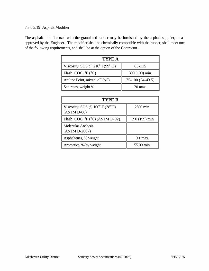
Lakehaven Utility District Sanitary Sewer Specifications (07/2002) SPEC-7-25
7.3.6.3.19 Asphalt Modifier The asphalt modifier used with the granulated rubber may be furnished by the asphalt supplier, or as approved by the Engineer. The modifier shall be chemically compatible with the rubber, shall meet one of the following requirements, and shall be at the option of the Contractor.
TYPE A
Viscosity, SUS @ 210o F(99o C) 85-115
Flash, COC, oF (oC) 390 (199) min.
Aniline Point, mixed, oF (oC) 75-100 (24-43.5)
Saturates, weight % 20 max.
TYPE B
Viscosity, SUS @ 100o F (38oC) (ASTM D-88)
2500 min.
Flash, COC, oF (oC) (ASTM D-92). 390 (199) min
Molecular Analysis (ASTM D-2007)
Asphaltenes, % weight 0.1 max.
Aromatics, % by weight 55.00 min.
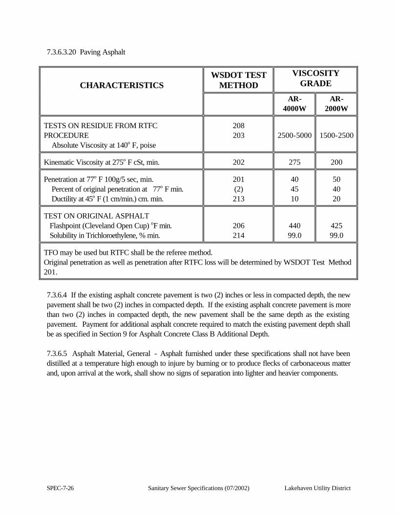
SPEC-7-26 Sanitary Sewer Specifications (07/2002) Lakehaven Utility District
7.3.6.3.20 Paving Asphalt
CHARACTERISTICS
WSDOT TEST METHOD
VISCOSITY GRADE
AR-
4000W AR-
2000W TESTS ON RESIDUE FROM RTFC PROCEDURE Absolute Viscosity at 140o F, poise
208 203
2500-5000
1500-2500
Kinematic Viscosity at 275o F cSt, min.
202
275
200
Penetration at 77o F 100g/5 sec, min. Percent of original penetration at 77o F min. Ductility at 45o F (1 cm/min.) cm. min.
201 (2) 213
40 45 10
50 40 20
TEST ON ORIGINAL ASPHALT Flashpoint (Cleveland Open Cup) oF min. Solubility in Trichloroethylene, % min.
206 214
440 99.0
425 99.0
TFO may be used but RTFC shall be the referee method. Original penetration as well as penetration after RTFC loss will be determined by WSDOT Test Method
201.
7.3.6.4 If the existing asphalt concrete pavement is two (2) inches or less in compacted depth, the new pavement shall be two (2) inches in compacted depth. If the existing asphalt concrete pavement is more than two (2) inches in compacted depth, the new pavement shall be the same depth as the existing pavement. Payment for additional asphalt concrete required to match the existing pavement depth shall be as specified in Section 9 for Asphalt Concrete Class B Additional Depth. 7.3.6.5 Asphalt Material, General - Asphalt furnished under these specifications shall not have been distilled at a temperature high enough to injure by burning or to produce flecks of carbonaceous matter and, upon arrival at the work, shall show no signs of separation into lighter and heavier components.
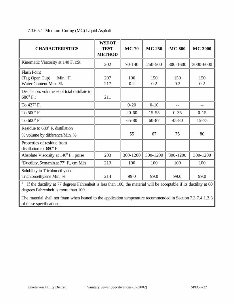
Lakehaven Utility District Sanitary Sewer Specifications (07/2002) SPEC-7-27
7.3.6.5.1 Medium-Curing (MC) Liquid Asphalt
CHARACTERISTICS
WSDOT TEST
METHOD
MC-70
MC-250
MC-800
MC-3000
Kinematic Viscosity at 140 F. cSt 202
70-140
250-500
800-1600
3000-6000
Flash Point (Tag Open Cup) Min. oF. Water Content Max. %
207 217
100 0.2
150 0.2
150 0.2
150 0.2
Distillation: volume % of total distillate to 680o F.:
211
To 437o F. 0-20 0-10 -- --
To 500o F 20-60 15-55 0-35 0-15
To 600o F 65-80 60-87 45-80 15-75
Residue to 680o F. distillation % volume by difference/Min. %
55
67
75
80
Properties of residue from distillation to 680o F.
Absolute Viscosity at 140o F., poise 203 300-1200 300-1200 300-1200 300-1200 1Ductility, 5cm/min.at 77o F., cm Min. 213 100 100 100 100
Solubility in Trichloroethylene Trichloroethylene Min. %
214
99.0
99.0
99.0
99.0
1 If the ductility at 77 degrees Fahrenheit is less than 100, the material will be acceptable if its ductility at 60 degrees Fahrenheit is more than 100.
The material shall not foam when heated to the application temperature recommended in Section 7.3.7.4.1.3.3 of these specifications.
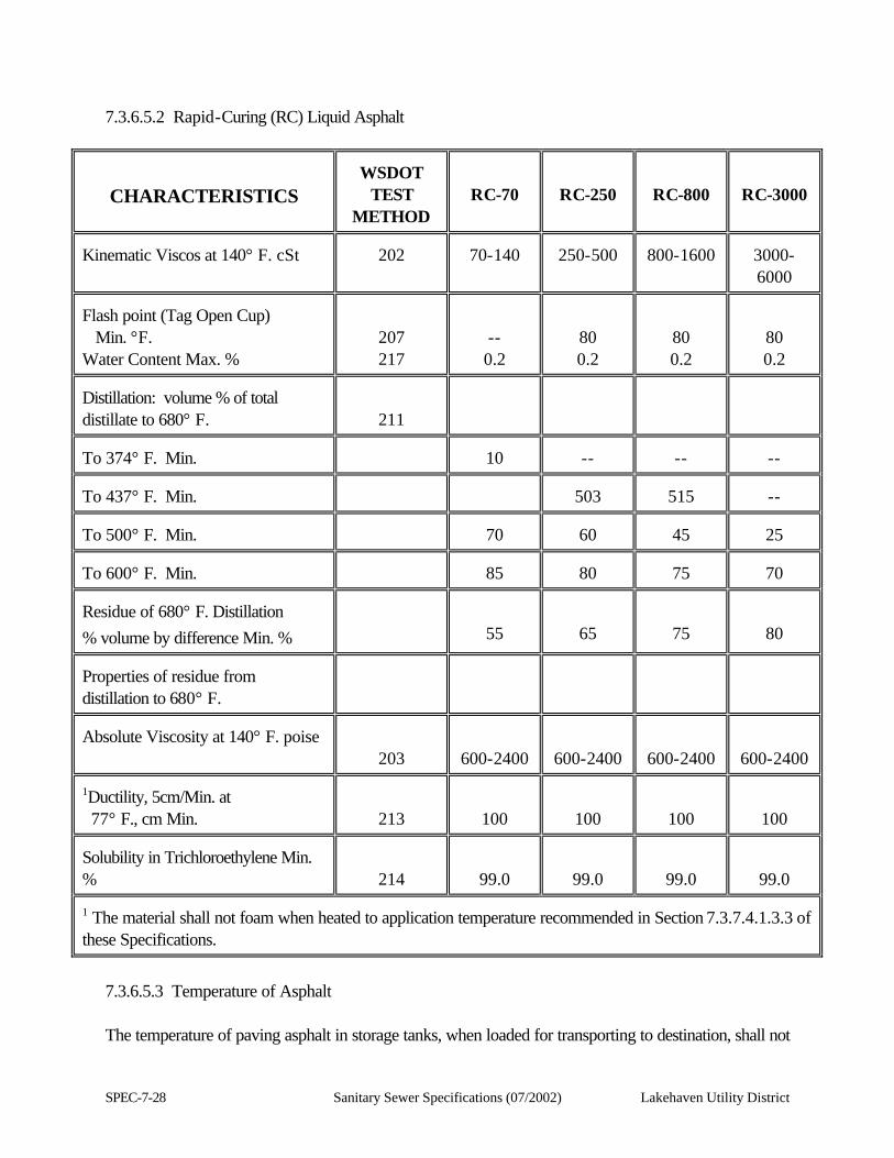
SPEC-7-28 Sanitary Sewer Specifications (07/2002) Lakehaven Utility District
7.3.6.5.2 Rapid-Curing (RC) Liquid Asphalt
CHARACTERISTICS
WSDOT
TEST METHOD
RC-70
RC-250
RC-800
RC-3000
Kinematic Viscos at 140° F. cSt
202
70-140
250-500
800-1600
3000-6000
Flash point (Tag Open Cup) Min. °F. Water Content Max. %
207 217
-- 0.2
80 0.2
80 0.2
80 0.2
Distillation: volume % of total distillate to 680° F.
211
To 374° F. Min.
10
--
--
--
To 437° F. Min.
503
515
--
To 500° F. Min.
70
60
45
25
To 600° F. Min.
85
80
75
70
Residue of 680° F. Distillation % volume by difference Min. %
55
65
75
80 Properties of residue from distillation to 680° F.
Absolute Viscosity at 140° F. poise
203
600-2400
600-2400
600-2400
600-2400 1Ductility, 5cm/Min. at 77° F., cm Min.
213
100
100
100
100 Solubility in Trichloroethylene Min. %
214
99.0
99.0
99.0
99.0 1 The material shall not foam when heated to application temperature recommended in Section 7.3.7.4.1.3.3 of these Specifications.
7.3.6.5.3 Temperature of Asphalt The temperature of paving asphalt in storage tanks, when loaded for transporting to destination, shall not

Lakehaven Utility District Sanitary Sewer Specifications (07/2002) SPEC-7-29
be greater than 400 degrees Fahrenheit.
SPEC-7-30 Sanitary Sewer Specifications (07/2002) Lakehaven Utility District
7.3.6.5.4 Anti-Stripping Additive When called for in the Contract Drawings, Special Provisions, or as called for by the Engineer, asphalt material shall be treated with an approved heat-stable anti-stripping additive before use. Anti-stripping additive in the amount of one (1) percent by weight of the asphalt, or less if ordered by the Engineer, shall be added to the asphalt at the point of shipment. The anti-stripping additive shall be analyzed by an independent testing laboratory at the Contractor's expense and approved by the Engineer prior to use. 7.3.7 Bituminous Surface Treatment Pavement 7.3.7.1 Restoration of bituminous surface treatment pavement shall be accomplished by removing the entire existing bituminous surface treated area and replacing it with either asphalt concrete pavement (Type A Restoration) or a new bituminous surface treatment pavement (Type B Restoration), as directed by the Engineer. The Engineer, at his/her discretion, can require the installation of either or both types of bituminous surface treatment restoration on this project. 7.3.7.2 On bituminous surface treatment streets, neat lines shall be cut after all pipeline construction. The Contractor shall remove all damaged existing surfaces, before paving, at his/her cost. No other payment other than the pay limits specified in Section 9 of these specifications will be allowed. 7.3.7.3 Type A Restoration Type A restoration shall be asphalt concrete pavement construction as shown in the pavement restoration sections for bituminous surface treatment. Unless otherwise directed by the Engineer, the new pavement shall have the same plan dimensions and grade as the pavement that existed prior to construction. 7.3.7.3.1 Asphalt concrete shall be Class B as specified in Section 7.3.6.2.3. Aggregate for asphalt concrete shall conform to the requirement of Sections 7.3.6.2.1 through 7.3.6.2.7, inclusive. Asphalt binder shall be paving asphalt as specified in Section 7.3.6.3.20. The asphalt content of the mixture shall be six (6) percent as defined in Section 7.3.6.3. 7.3.7.3.2 The construction of asphalt concrete pavement restoration shall conform to the applicable requirements of Section 7.3.6. The compacted depth of any one lift shall not exceed two (2) inches. 7.3.7.4 Type B Restoration Type B restoration shall be new bituminous surface treatment pavement constructed as shown in the pavement restoration sections for bituminous surface treatment. Unless otherwise directed by the Engineer, the new pavement shall have the same plan dimensions and grade as the pavement that existed prior to construction.
Lakehaven Utility District Sanitary Sewer Specifications (07/2002) SPEC-7-31
7.3.7.4.1 Bituminous Surface Treatment This work shall consist of constructing a single or multiple course bituminous surface treatment in accordance with these specifications and in reasonably close conformity with the lines and cross-sections shown in the Contract Drawings or as directed by the Engineer. 7.3.7.4.1.1 Bituminous Surface Treatment Class A This method of treatment requires two (2) applications of asphalt and two (2) applications of aggregate as specified. The second application (tack coat) shall be applied not less than five (5) days after the first application (prime coat) for cutback asphalt and as approved by the Engineer for emulsified asphalt. 7.3.7.4.1.2 Materials Materials shall meet the requirements of the following sections of these specifications:
Asphalt (grade specified) . . . . . 7.3.6.5 Aggregates . . . . . . . . . . . . . . . . 7.3.6.2 Anti-Stripping Additive . . . . . . 7.3.6.5.4
Aggregate to be used for bituminous surface treatment shall be of the type and size called for in the Contract Drawings or Special Provisions of the Contract. The particular asphalt to be used on any project shall be that which is called for in the Special Provisions of the Contract or shown in the Contract Drawings, and may be conditionally accepted at the source by the Engineer. 7.3.7.4.1.3 Construction Requirements 7.3.7.4.1.3.1 Equipment The equipment used by the Contractor shall include scarifying, mixing, spreading, finishing and compacting equipment, an asphalt distributor, and equipment for heating asphalt material and shall be subject to approval by the Engineer before its use on the work. The distributor shall have a capacity of not less than 1,000 gallons, and shall be so designed, equipped, maintained and operated that asphalt material of an even heat shall be uniformly applied at the required rate. It shall be equipped with a ten (10) foot spray bar with extensions, pressure pump and gauge, volume gauge so located as to be observed easily by the Inspector from the ground, a tachometer to control accurately the speed and spread of asphalt, and two (2) thermometers [one (1) installed permanently in the tank to indicate temperatures of the asphalt at all times]. The power for operating the pressure pump shall be supplied by a power unit that will develop a minimum of 25 psi pressure at the spray bar.
SPEC-7-32 Sanitary Sewer Specifications (07/2002) Lakehaven Utility District
Rollers shall be self-propelled pneumatic-tired or smooth-wheeled rollers, weighing not less than ten (10) tons. Spreading equipment shall be self-propelled and supported on at least four (4) pneumatic tires, with an approved devise for accurately metering and distributing the aggregate uniformly over the roadway surface. Such other equipment as may be necessary to satisfactorily perform the work, as specified herein or as directed by the Engineer, shall be subject to approval by the Engineer before its use on the work. Additional units shall be placed on the work when, in the opinion of the Engineer, it is considered necessary in order to fulfill the requirements of these specifications, or to complete the work within the time specified. 7.3.7.4.1.3.2 Preparation of Roadway Surface 7.3.7.4.1.3.2.1 Untreated Surfaces The existing roadway surface shall be shaped to a uniform grade and section as shown in the Contract Drawings or as directed by the Engineer. The roadway shall be sprinkled, bladed, and rolled, after which the top one (1) inch of dampened material shall be bladed back and forth across the roadway until the entire roadway surface shows a uniform grading from coarse to fine and conforms to the line, grade and cross-section shown in the Contract Drawings, or staked by the Engineer. With cutback asphalt, the entire surface shall then be rolled with a smooth-wheeled or pneumatic-tired roller, or both, as directed by the Engineer, except that the final rolling shall be accomplished with a smooth-wheeled roller as specified in Section 7.3.7.4.1.3.1. Rolling shall continue until the entire roadway presents a firm and unyielding surface. For emulsified asphalt, no compaction shall be allowed after the top one (1) inch has been processed as described above until after the first application of asphalt. During the operation of blading and rolling, water shall be applied, if necessary, in the amount and at the locations directed by the Engineer. Immediately before the prime coat of asphalt is applied, the roadway surface shall be stable and unyielding, dry to medium damp condition, free from irregularities and material segregation, and true to line, grade and cross-section. In the event the compacted aggregates are of such gradation as to resist penetration of the asphalt, the Contractor shall loosen no more than the upper 1/2-inch of surface and relay without compaction immediately before the prime coat application. Following the application of aggregate on the prime coat, rolling shall be performed as specified above.

Lakehaven Utility District Sanitary Sewer Specifications (07/2002) SPEC-7-33
SPEC-7-34 Sanitary Sewer Specifications (07/2002) Lakehaven Utility District
The Contractor shall patch with premixed materials any holes or other malformations that cannot be removed by blading. The premixed material shall be made of crushed surfacing top course or cover stone from existing stockpiles mixed on the roadway with the asphalt specified for the project, by such road mix methods, as may be directed by the Engineer. All small patches shall be thoroughly hand-tamped and the larger holes or areas shall be patched and rolled with a smooth-wheeled roller or a two-axle power patching roller. 7.3.7.4.1.3.2.2 Treated Surfaces The existing bituminous surface shall be swept with a power broom until it is free from dirt or other foreign matter. Hand push brooms shall be used to clean omissions of the power broom. As soon as the existing surface has been thoroughly cleaned, all holes in the surface, edges and edge breaks shall be patched. The holes and breaks shall be thoroughly cleaned of all dirt and loose material. For shallow holes and breaks, a small amount of asphalt shall be placed in the bottom of the hole, covered with mineral aggregate and be thoroughly tamped or rolled. For holes one (1) inch or more in depth, a premix material of mineral aggregate mixed with asphalt, as directed by the Engineer, shall be used. Asphalt used for patching shall be heated to the temperature specified in Section 7.3.6.5. Before placing the premix material in the hole, the bottom and edges of the hole shall be swabbed with asphalt. The premixed material shall then be placed and thoroughly tamped or rolled. A small amount of fine screenings shall then be spread on the top of the patch. Larger depression areas shall be corrected by pre-leveling with premix material or with successive applications of bituminous surface treatment as shown in the Contract Drawings or as directed by the Engineer to re-establish a crown-section. All costs for patching as described above shall be included in the unit contract price per ton for "Asphalt (grade)" and per cubic yard for "Mineral Aggregate From Stockpile for BST." 7.3.7.4.1.3.2.3 Soil Residual Herbicide Where shown in the Contract or on the Contract Drawings, soil residual herbicide shall be applied in accordance with the Washington State Regulations. The soil residual herbicide to be used shall not have a detrimental chemical reaction to the asphalt pavement or damage the pavement. Application of the herbicide shall be a uniform spray in accordance with the manufacturer's recommendations.
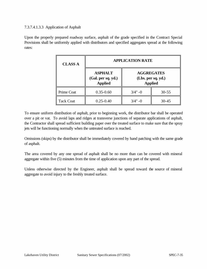
Lakehaven Utility District Sanitary Sewer Specifications (07/2002) SPEC-7-35
7.3.7.4.1.3.3 Application of Asphalt Upon the properly prepared roadway surface, asphalt of the grade specified in the Contract Special Provisions shall be uniformly applied with distributors and specified aggregates spread at the following rates:
CLASS A
APPLICATION RATE
ASPHALT
(Gal. per sq. yd.) Applied
AGGREGATES (Lbs. per sq. yd.)
Applied Prime Coat
0.35-0.60
3/4" -0
30-55
Tack Coat
0.25-0.40
3/4" -0
30-45
To ensure uniform distribution of asphalt, prior to beginning work, the distributor bar shall be operated over a pit or vat. To avoid laps and ridges at transverse junctions of separate applications of asphalt, the Contractor shall spread sufficient building paper over the treated surface to make sure that the spray jets will be functioning normally when the untreated surface is reached. Omissions (skips) by the distributor shall be immediately covered by hand patching with the same grade of asphalt. The area covered by any one spread of asphalt shall be no more than can be covered with mineral aggregate within five (5) minutes from the time of application upon any part of the spread. Unless otherwise directed by the Engineer, asphalt shall be spread toward the source of mineral aggregate to avoid injury to the freshly treated surface.
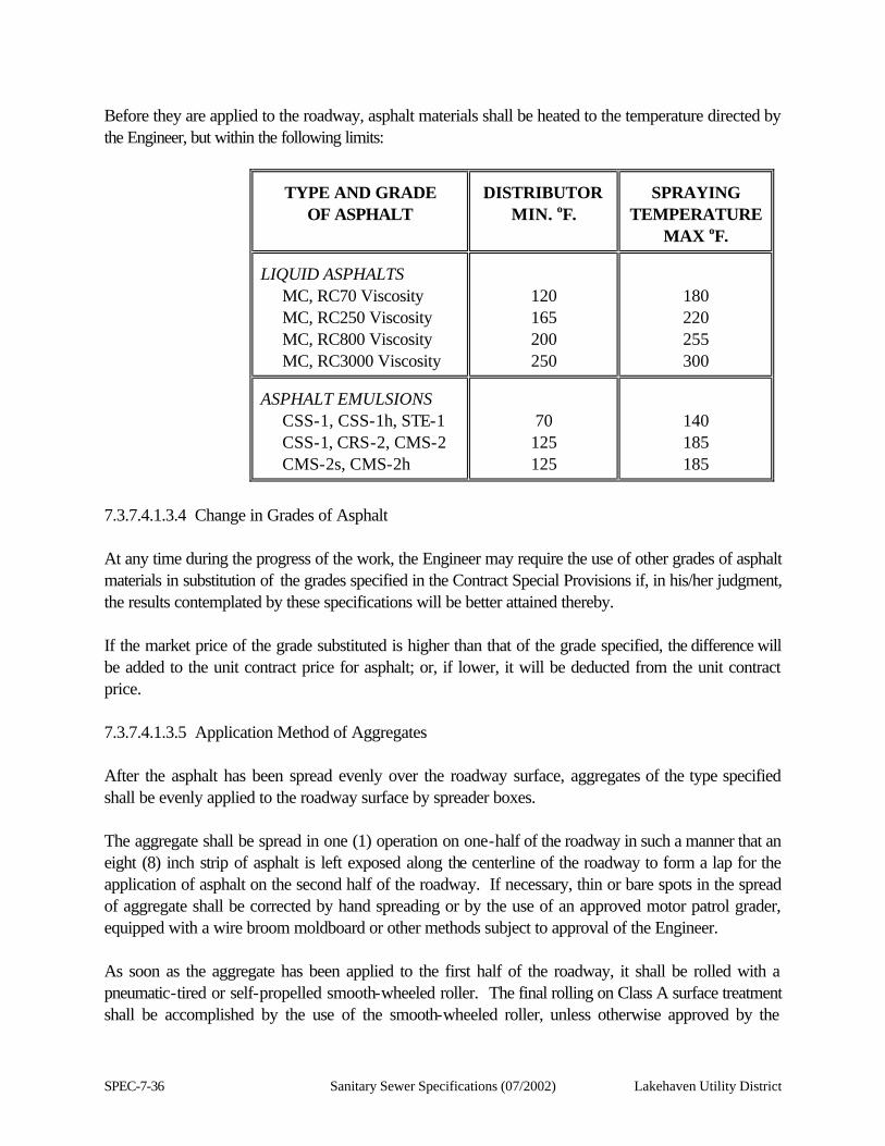
SPEC-7-36 Sanitary Sewer Specifications (07/2002) Lakehaven Utility District
Before they are applied to the roadway, asphalt materials shall be heated to the temperature directed by the Engineer, but within the following limits:
TYPE AND GRADE
OF ASPHALT
DISTRIBUTOR
MIN. oF.
SPRAYING
TEMPERATURE MAX oF.
LIQUID ASPHALTS MC, RC70 Viscosity MC, RC250 Viscosity MC, RC800 Viscosity MC, RC3000 Viscosity
120 165 200 250
180 220 255 300
ASPHALT EMULSIONS CSS-1, CSS-1h, STE-1 CSS-1, CRS-2, CMS-2 CMS-2s, CMS-2h
70 125 125
140 185 185
7.3.7.4.1.3.4 Change in Grades of Asphalt At any time during the progress of the work, the Engineer may require the use of other grades of asphalt materials in substitution of the grades specified in the Contract Special Provisions if, in his/her judgment, the results contemplated by these specifications will be better attained thereby. If the market price of the grade substituted is higher than that of the grade specified, the difference will be added to the unit contract price for asphalt; or, if lower, it will be deducted from the unit contract price. 7.3.7.4.1.3.5 Application Method of Aggregates After the asphalt has been spread evenly over the roadway surface, aggregates of the type specified shall be evenly applied to the roadway surface by spreader boxes. The aggregate shall be spread in one (1) operation on one-half of the roadway in such a manner that an eight (8) inch strip of asphalt is left exposed along the centerline of the roadway to form a lap for the application of asphalt on the second half of the roadway. If necessary, thin or bare spots in the spread of aggregate shall be corrected by hand spreading or by the use of an approved motor patrol grader, equipped with a wire broom moldboard or other methods subject to approval of the Engineer. As soon as the aggregate has been applied to the first half of the roadway, it shall be rolled with a pneumatic-tired or self-propelled smooth-wheeled roller. The final rolling on Class A surface treatment shall be accomplished by the use of the smooth-wheeled roller, unless otherwise approved by the
Lakehaven Utility District Sanitary Sewer Specifications (07/2002) SPEC-7-37
Engineer. After the application of asphalt and aggregate to the first half of the roadway, the remaining half of the roadway shall be prepared and treated in the same manner as described for the first half. Where there is an excess of aggregate, it shall be distributed evenly over the adjacent roadway surface by brooming or it may be picked up by shoveling into spot trucks. Where specified, the application of fine aggregate shall be applied as soon after the application of the coarse aggregate as the Engineer may deem necessary to prevent pick up and produce a good riding surface. Immediately after the fine aggregate has been spread with an approved spreader box, the roadway surface shall be inspected and be broomed, if needed, with an approved road broom for the purpose of providing an even and uniform distribution of the material. The work shall be performed in a manner that will not disturb the asphalt or the coarser aggregate upon it. As soon as the aggregate has been uniformly spread, the completed surface shall be thoroughly rolled with a pneumatic-tired roller. Final rolling with a smooth-wheeled roller may be required. Brooming shall be continued for five (5) days following the application of the aggregate, as directed by the Engineer, to ensure that any bleeding or pick up due to traffic does not occur. During the five (5) day period, any extra aggregate the Engineer may deem necessary to correct defects shall be applied in the amount and at the place designated by the Engineer at the unit contract price for the kind of mineral aggregate specified in the Contract. Should conditions warrant removal of excess aggregates prior to the completion of the five (5) day period, the Engineer may direct such removal. In the event of the Contractor's failure or neglect to faithfully perform this maintenance, resulting in damage to the surface, the Contractor at his/her expense shall make the necessary repairs to the satisfaction of the Engineer. The speed and load of trucks hauling mineral aggregate from the stockpile shall be so regulated that no damage, as determined by the Engineer, will result to the highway or the freshly applied asphalt surface. 7.3.7.4.1.3.6 Additional Asphalt and Aggregate If the application of asphalt or mineral aggregate, or both, placed on any particular portions of roadway is insufficient or excessive for the required results, the Engineer may direct the Contractor to make an additional application of one or both materials in accordance with these specifications or the Engineer's directions.
SPEC-7-38 Sanitary Sewer Specifications (07/2002) Lakehaven Utility District
7.3.7.4.1.3.7 Patching and Correction of Defects Omissions by the distributor or damage to the treated surface of any coat shall be immediately covered by hand patching with asphalt in adequate quantities. Holes that develop in the surface shall be patched in the same manner as specified for patching in Section 7.3.7.4.1.3.2.1. All costs incurred by the Contractor, in coating omissions and patching, shall be included in the unit contract prices for the materials used. Defects such as raveling, lack of uniformity or other imperfections caused by faulty workmanship shall be corrected as directed by the Engineer and new work shall not be started until such defects have been remedied. All improper workmanship and defective materials resulting from overheating, improper handling or application, shall be removed from the roadway by the Contractor and be replaced with approved materials and workmanship at his/her expense. 7.3.7.4.1.3.8 Protection of Structures All bridge handrails, guardrails, curbs, road signs, or other facilities shall be protected from splashing of the asphalt. All costs incurred by the Contractor in necessary protective measures shall be included in the unit contract prices for the various pay items of work involved. 7.3.7.4.1.3.9 Unfavorable Weather Asphalt shall not be applied to wet material. Subject to the determination of the Engineer, asphalt shall not be applied during rainfall, sand or dust storms, or before any imminent storms that might damage the construction. The Engineer shall have the discretion as to whether the surface and materials are dry enough to proceed with construction. The application of any asphalt to the roadway shall be restricted to the following conditions: The ground temperature shall be at least 60 degrees Fahrenheit and the air temperature at least 60 degrees Fahrenheit and rising or the air temperature shall be not less than 70 degrees Fahrenheit when falling and the wind shall be less than five (5) miles per hour as estimated by the Engineer. No asphalt shall be applied which cannot be covered one hour before darkness. The Engineer may require the Contractor to delay application of asphalt until the atmospheric and roadway conditions are satisfactory. Construction of bituminous surface treatments on any traveled way shall not be carried out before May 15 or after August 15 of any year, except upon written order of the General Manager.

Lakehaven Utility District Sanitary Sewer Specifications (07/2002) SPEC-7-39
7.3.7.4.1.3.10 Anti-Stripping Additive When called for in the Contract Special Provisions, or ordered by the Engineer, asphalt material shall be treated with anti-stripping additive in accordance with Section 7.3.6.5.4 of these specifications. 7.3.8 Cement Concrete Pavement 7.3.8.1 Description This work shall consist of constructing a pavement composed of Portland cement concrete on a prepared subgrade or base course in accordance with these specifications and in reasonably close conformity with the lines, grades, thickness', and typical cross-sections shown in the Contract Drawings or established by the Engineer. 7.3.8.1.1 The restoration of cement concrete pavement shall be accomplished by patching the trench area as shown on the Contract Drawings for pavement restoration section for cement concrete. The patch shall conform to the grade existing prior to construction and shall provide a smooth, continuous restoration of the pavement surface. 7.3.8.2 Materials 7.3.8.2.1 Types of Cement Cement shall be classified as (a) Type II Portland cement, or (b) Type III Portland cement. 7.3.8.2.1.1 Specifications 7.3.8.2.1.1.1 Type II Portland Cement Type II Portland cement shall conform to the requirements for Type II cement of the Standard Specifications for Portland Cement, AASHTO Designations M 85, except that the content of alkalies shall not exceed 0.75 percent by weight calculated as Na20 plus 0.658 K20. Type II Portland cement shall meet the requirements of the above specifications for compressive strength and for time of setting by both the Gillmore and Vicat methods. 7.3.8.2.1.1.2 Type III Portland Cement Type III Portland cement in cloth bags shall not be used. Type III Portland cement shall conform to the requirements for Type III cement of the Standard Specifications for Portland Cement, AASHTO Designation M 85, except that the content of alkalies shall not exceed 0.75 percent by weight calculated as Na20 plus 0.658 K20. It shall meet the requirements of the above specifications for compressive strength and for time of setting by both the Gillmore and the Vicat methods.
SPEC-7-40 Sanitary Sewer Specifications (07/2002) Lakehaven Utility District
7.3.8.2.1.1.3 Low Alkali Cement When the Contract Special Provisions state that low-alkali cement shall be used, the percentage of alkalies in the cement shall not exceed 0.60 percent by weight calculated as Na20 plus 0.658 K20. This limitation shall apply to all types of Portland cement. 7.3.8.2.1.1.4 Tests and Acceptance Cement will be accepted on the basis of the manufacturer's certification that it meets all of the requirements of these specifications. All shipments of the cement to the Contractor or Ready-Mix concrete supplier shall be accompanied by Certification of Cement Shipment. The Ready-Mix supplier or Contractor shall countersign three (3) copies of this certificate and submit all three (3) copies to the Engineer. Cement will be tested using samples taken at the job site by the Engineer for submission to an independent testing laboratory for analysis. Each mixing facility or plant utilizing Portland cement shall be equipped with a suitable means or device for obtaining a representative sample of the Portland cement. The device shall enable the sample to be readily taken in close proximity to the cement weight hopper and from a container or conveyor holding only Portland cement. 7.3.8.2.1.1.5 Storage on the Work Site The cement shall be stored on the site in such a manner as to permit easy access for inspection and identification. Cement shall be adequately protected at all times from rain and dampness. Any cement that, in the opinion of the Engineer, contains lumps that will not be pulverized in the mixer, shall be rejected. Type III Portland cement stored by the Contractor for a period longer than 30 days, or Type II Portland cement stored by the Contractor for a period longer than 60 days, shall be held for retest. If the cement has lost strength during the period of storage, as shown by the independent testing laboratory analysis, sufficient additional cement shall be added to the mix at the Contractor's expense to overcome such loss, or the cement may be rejected by the Engineer. The amount of cement to be added to the mix shall be determined by the Engineer and shall be final and binding upon the Contractor. 7.3.8.2.1.1.6 Ready-Mixed Concrete Ready-mixed concrete may be used, if approved by the Engineer. Approval will be given if inspection of the plant and delivery system indicate they are capable of delivering to the project site concrete conforming in all respects with the requirements of these specifications and the Contract Special Provisions.
Lakehaven Utility District Sanitary Sewer Specifications (07/2002) SPEC-7-41
If the use of ready-mix concrete is approved, the producer will be authorized to use cement upon certification by the manufacturer that the cement meets all the requirements of these specifications and the Contract Special Provisions. Certified cement shall be stored at the concrete plant in such a manner that it can be identified and kept separate from other cement. Ready-mixed concrete may be produced by stationary mixers or truck mixers. Agitation of the concrete, subsequent to mixing, may be done by truck mixers or truck agitators. Each mixer and agitator shall have attached thereto, in a prominent place, a metal plate or plates on which is plainly marked, for the various uses for which the equipment is designed, the capacity of the drum or container in terms of the volume of mixed concrete and the speed of rotation of the mixing drum or blades. Stationary mixers shall be equipped with an acceptable timing device that will not permit the batch to be discharged until the specified mixing time has elapsed. Truck mixers or agitators transporting central-mixed, shrink-mixed, or transit-mixed concrete shall be equipped with a non-resettable counter for recording the number of revolutions of the drum, blades or paddles. The mixer, when loaded to capacity, shall be capable of combining the ingredients of the concrete within the specified time into a thoroughly mixed and uniform mass and of discharging the concrete with a satisfactory degree of uniformity. The agitator, when loaded to capacity, shall be capable of maintaining the mixed concrete in a thoroughly mixed and uniform mass and of discharging the concrete with a satisfactory degree of uniformity. Slump tests may be made of individual samples taken at approximately the 1/4 and the 3/4 points of the load and if the slumps differ by more than two (2) inches, the mixer or agitator shall not be used until the condition is corrected. If the slump test is not satisfactorily met by mixers, when operated during the minimum specified mixing time and loaded to capacity, or by agitators, when loaded to capacity, the equipment may still be used when operation with a longer mixing time or with a smaller load will produce concrete that will meet the slump tests. Mixers and agitators shall be examined daily for changes in condition due to accumulation of hardened concrete or mortar or to wear of the blades. When any such change of condition is found, the concrete shall be subjected to the slump tests. If the tests indicated that the concrete is not being properly mixed, the faulty equipment shall be corrected before its further use is allowed. Ready-mixed concrete shall be mixed and delivered by means of one (1) of the following combinations of operations: 1. Mixed completely in a stationary mixer and the mixed concrete transported to the point of delivery
in a truck agitator or in a truck mixer operating at agitator speed (known as central-mixed concrete).
2. Mixed partially in a stationary mixer and the mixing completed in a truck mixer (known as shrink-
SPEC-7-42 Sanitary Sewer Specifications (07/2002) Lakehaven Utility District
mixed concrete).
3. Mixed completely in a truck mixer (known as transit-mixed concrete). The mixing must be performed under the surveillance of an inspector either at the plant site or at the jobsite. Mixers and agitators shall be operated within the limits of capacity and speed of rotation designated by the manufacturer of the equipment. When a stationary mixer is used for partial mixing of the concrete (shrink-mixing), the mixing time in the stationary mixer may be reduced to the minimum required to intermingle the ingredients (about 30 seconds). When a truck mixer is used either for complete mixing or to finish the partial mixing done in a stationary mixer, each batch of concrete shall be mixed for not less than 70 nor more than 100 revolutions of the drum or blades at the rate of rotation designated by the manufacturer of the equipment as mixing speed. If any additional mixing is done, it shall be at the speed designated by the manufacturer of the equipment as agitating speed. When a truck mixer or truck agitator is used for transporting concrete that has been completely mixed in a stationary mixer, mixing during transportation shall be at the speed designated by the manufacturer of the equipment as agitating speed. When a truck mixer or agitator is used for transporting concrete, the concrete shall be delivered to the site of the work and discharge shall be completed with 1-1/2 hours after the introduction of the cement to the mix. In hot weather or under conditions contributing to quick stiffening of the concrete, a delivery time of less than 1-1/2 hours may be required. When a truck mixer is used for the complete mixing of the concrete, the mixing operation shall begin within 30 minutes after the cement has been intermixed with the aggregates. Concrete transported in a truck mixer or agitator shall not have been subjected to more than 250 revolutions of the drum or blades at the time it is placed in the work. Intermittent agitation of the concrete will be permitted in order to stay below the maximum of 250 revolutions provided that the time limit of 1-1/2 hours after the introduction of the cement to the mix is not exceeded. The organization supplying concrete shall have sufficient plant capacity and transporting apparatus to ensure continuous delivery at the rate required. The methods of delivering and handling the concrete shall be such as will facilitate placing with a minimum of rehandling without damage to the structure of the concrete.
7.3.8.2.2 Aggregates for Portland Cement Concrete 7.3.8.2.2.1. General Requirements
Lakehaven Utility District Sanitary Sewer Specifications (07/2002) SPEC-7-43
Portland cement concrete aggregates shall be manufactured from ledge rock, talus, or sand and gravel and shall possess such characteristics of shape and size that concrete, resulting from a mixture of fine and coarse aggregates in the specified proportions, will be of workability that is satisfactory to the Engineer. Regardless of compliance with all other sections of these specifications, if the concrete is not of a workable character, or when finished does not exhibit a proper surface, either by the fine or the coarse aggregate, or both, it shall be rejected or altered as required by the Engineer. If, in the judgment of the Engineer, based on previous experience or on laboratory tests, concrete aggregates from a given source are detrimentally reactive with alkalies in Portland cement, they shall be used in concrete in combination with low-alkali cement only. 7.3.8.2.2.2 Fine Aggregate for Portland Cement Concrete Fine aggregate shall consist of sand or other inert materials, or combinations thereof, approved by the Engineer, having hard, strong, durable particles free from adherent coating. Fine aggregate shall be washed thoroughly to remove clay, loam, alkali, organic matter, or other deleterious matter. 7.3.8.2.2.2.1 Deleterious Substances The amount of deleterious substances in the washed aggregate shall not exceed the following values: (1) Amount finer than U.S. No. 200 sieve……………2.0 percent by weight.
(2) Particles of specific gravity less than 1.95………..1.0 percent by weight.
(3) Organic matter, by colorimetric test, shall not be darker than the reference standard color ASTM Designation C 40, unless other tests prove a darker color to be harmless.
7.3.8.2.2.2.2 Grading Fine aggregate for Portland cement concrete shall be Class 1 or 2 gradation only. Class 1 may be used for all classes of concrete; Class 2 use will be limited to concrete Class B or C. Fine aggregate Class 1 shall be uniformly graded from coarse to fine and, when separated by means of U.S. Standard sieves, shall conform to the following requirements expressed as percentages by weight:
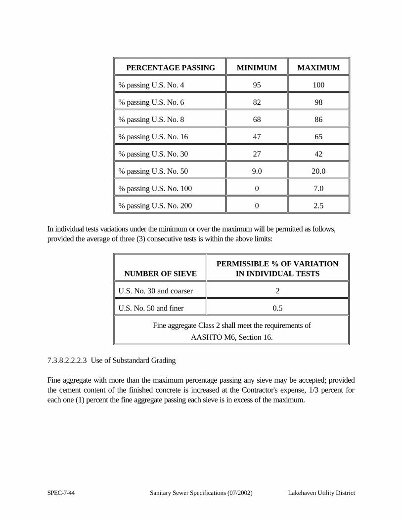
SPEC-7-44 Sanitary Sewer Specifications (07/2002) Lakehaven Utility District
PERCENTAGE PASSING
MINIMUM
MAXIMUM % passing U.S. No. 4
95
100
% passing U.S. No. 6
82
98
% passing U.S. No. 8
68
86
% passing U.S. No. 16
47
65
% passing U.S. No. 30
27
42
% passing U.S. No. 50
9.0
20.0
% passing U.S. No. 100
0
7.0
% passing U.S. No. 200
0
2.5
In individual tests variations under the minimum or over the maximum will be permitted as follows, provided the average of three (3) consecutive tests is within the above limits:
NUMBER OF SIEVE
PERMISSIBLE % OF VARIATION
IN INDIVIDUAL TESTS U.S. No. 30 and coarser
2
U.S. No. 50 and finer
0.5
Fine aggregate Class 2 shall meet the requirements of
AASHTO M6, Section 16.
7.3.8.2.2.2.3 Use of Substandard Grading Fine aggregate with more than the maximum percentage passing any sieve may be accepted; provided the cement content of the finished concrete is increased at the Contractor's expense, 1/3 percent for each one (1) percent the fine aggregate passing each sieve is in excess of the maximum.
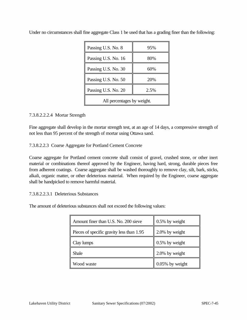
Lakehaven Utility District Sanitary Sewer Specifications (07/2002) SPEC-7-45
Under no circumstances shall fine aggregate Class 1 be used that has a grading finer than the following:
Passing U.S. No. 8
95%
Passing U.S. No. 16
80%
Passing U.S. No. 30
60%
Passing U.S. No. 50
20%
Passing U.S. No. 20
2.5%
All percentages by weight.
7.3.8.2.2.2.4 Mortar Strength Fine aggregate shall develop in the mortar strength test, at an age of 14 days, a compressive strength of not less than 95 percent of the strength of mortar using Ottawa sand. 7.3.8.2.2.3 Coarse Aggregate for Portland Cement Concrete Coarse aggregate for Portland cement concrete shall consist of gravel, crushed stone, or other inert material or combinations thereof approved by the Engineer, having hard, strong, durable pieces free from adherent coatings. Coarse aggregate shall be washed thoroughly to remove clay, silt, bark, sticks, alkali, organic matter, or other deleterious material. When required by the Engineer, coarse aggregate shall be handpicked to remove harmful material. 7.3.8.2.2.3.1 Deleterious Substances The amount of deleterious substances shall not exceed the following values:
Amount finer than U.S. No. 200 sieve
0.5% by weight
Pieces of specific gravity less than 1.95
2.0% by weight
Clay lumps
0.5% by weight
Shale
2.0% by weight
Wood waste
0.05% by weight
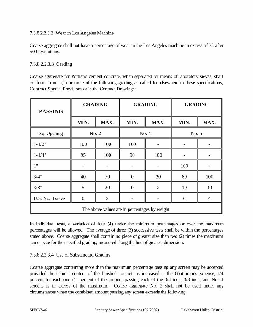
SPEC-7-46 Sanitary Sewer Specifications (07/2002) Lakehaven Utility District
7.3.8.2.2.3.2 Wear in Los Angeles Machine Coarse aggregate shall not have a percentage of wear in the Los Angeles machine in excess of 35 after 500 revolutions. 7.3.8.2.2.3.3 Grading Coarse aggregate for Portland cement concrete, when separated by means of laboratory sieves, shall conform to one (1) or more of the following grading as called for elsewhere in these specifications, Contract Special Provisions or in the Contract Drawings:
PASSING
GRADING
GRADING
GRADING
MIN.
MAX.
MIN.
MAX.
MIN.
MAX.
Sq. Opening
No. 2
No. 4
No. 5
1-1/2"
100
100
100
-
-
-
1-1/4"
95
100
90
100
-
-
1"
-
-
-
-
100
-
3/4"
40
70
0
20
80
100
3/8"
5
20
0
2
10
40
U.S. No. 4 sieve
0
2
-
-
0
4
The above values are in percentages by weight.
In individual tests, a variation of four (4) under the minimum percentages or over the maximum percentages will be allowed. The average of three (3) successive tests shall be within the percentages stated above. Coarse aggregate shall contain no piece of greater size than two (2) times the maximum screen size for the specified grading, measured along the line of greatest dimension. 7.3.8.2.2.3.4 Use of Substandard Grading Coarse aggregate containing more than the maximum percentage passing any screen may be accepted provided the cement content of the finished concrete is increased at the Contractor's expense, 1/4 percent for each one (1) percent of the amount passing each of the 3/4 inch, 3/8 inch, and No. 4 screens is in excess of the maximum. Coarse aggregate No. 2 shall not be used under any circumstances when the combined amount passing any screen exceeds the following:
Lakehaven Utility District Sanitary Sewer Specifications (07/2002) SPEC-7-47
3/4" square opening ......................70% 3/8" square opening ......................30% No. 4 square opening ................... 5%
Coarse aggregate No. 5 shall not be used under any circumstances when the combined amount passing any screen exceeds the following:
3/8" square opening.......................50% No. 4 square opening.................... 8%
7.3.8.2.2.3.5 Concrete Strength Concrete made from coarse aggregate, graded to comply with the requirements of these specifications, when combined with the specified proportions of cement and the fine aggregate proposed for use with the coarse aggregate, shall develop compressive and flexural strengths, at age of 14 days, of not less than 90 percent of that developed by concrete made from the same cement and washed sand and gravel from Steilacoom, Washington, of the same grading and mixed in the same proportions and to the same consistency. The increase of cement or the use of admixture will not be permitted for the purpose of qualifying aggregates. 7.3.8.2.3 Reinforcing Steel 7.3.8.2.3.1 Deformed Steel Bars Deformed steel bars for concrete reinforcement shall conform to the requirements of ASTM Designation A 615, Billet Steel Bars for Concrete Reinforcement, Grade 60, except as noted in the plans. However, in computing the ultimate unit tensile stress from test data, the area may be corrected for weight per linear foot of the bar within the weight tolerances listed. No such correction for weight shall be used in calculating the yield stress; the nominal area of the bar, as given in Table 1 of A 615, shall be used in this computation. 7.3.8.2.3.1.1 Bending Steel reinforcing bars shall be cut and bent by careful and competent workmen. They shall be bent cold to templates, which shall not vary appreciably from the shape and dimension shown in the Contract Drawings.
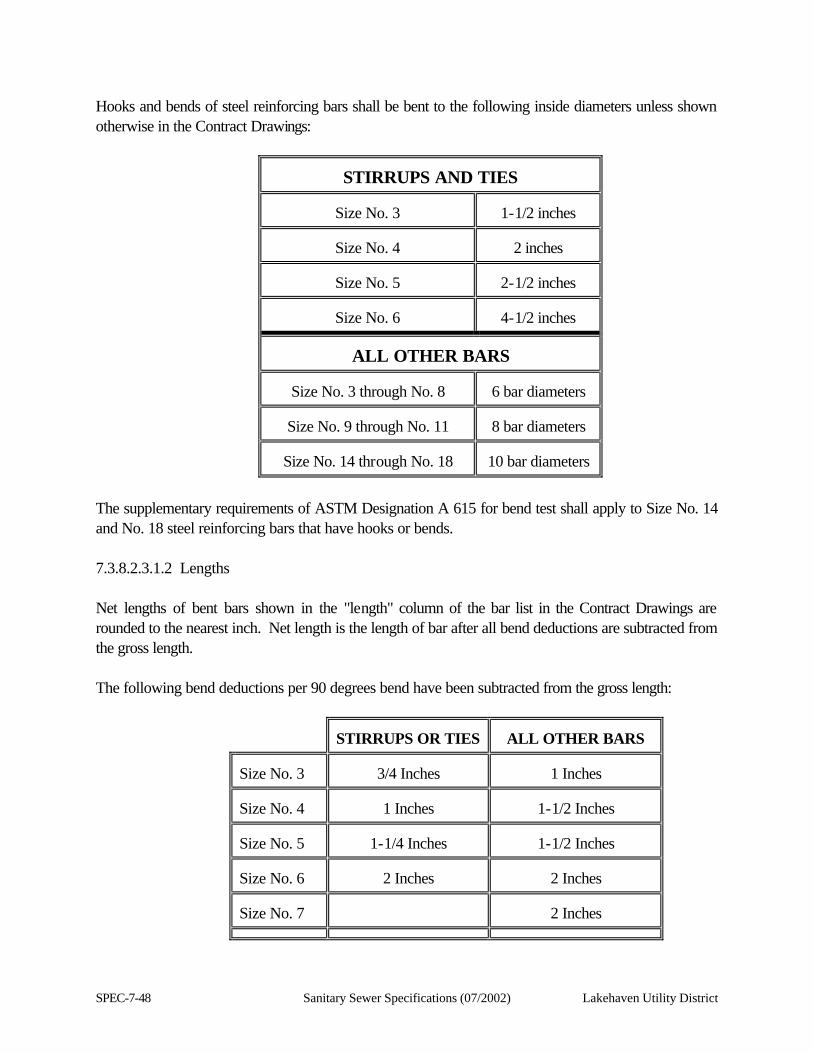
SPEC-7-48 Sanitary Sewer Specifications (07/2002) Lakehaven Utility District
Hooks and bends of steel reinforcing bars shall be bent to the following inside diameters unless shown otherwise in the Contract Drawings:
STIRRUPS AND TIES
Size No. 3
1-1/2 inches
Size No. 4
2 inches
Size No. 5
2-1/2 inches
Size No. 6
4-1/2 inches
ALL OTHER BARS
Size No. 3 through No. 8
6 bar diameters
Size No. 9 through No. 11
8 bar diameters
Size No. 14 through No. 18
10 bar diameters
The supplementary requirements of ASTM Designation A 615 for bend test shall apply to Size No. 14 and No. 18 steel reinforcing bars that have hooks or bends. 7.3.8.2.3.1.2 Lengths Net lengths of bent bars shown in the "length" column of the bar list in the Contract Drawings are rounded to the nearest inch. Net length is the length of bar after all bend deductions are subtracted from the gross length. The following bend deductions per 90 degrees bend have been subtracted from the gross length:
STIRRUPS OR TIES
ALL OTHER BARS
Size No. 3
3/4 Inches
1 Inches
Size No. 4
1 Inches
1-1/2 Inches
Size No. 5
1-1/4 Inches
1-1/2 Inches
Size No. 6
2 Inches
2 Inches
Size No. 7
2 Inches
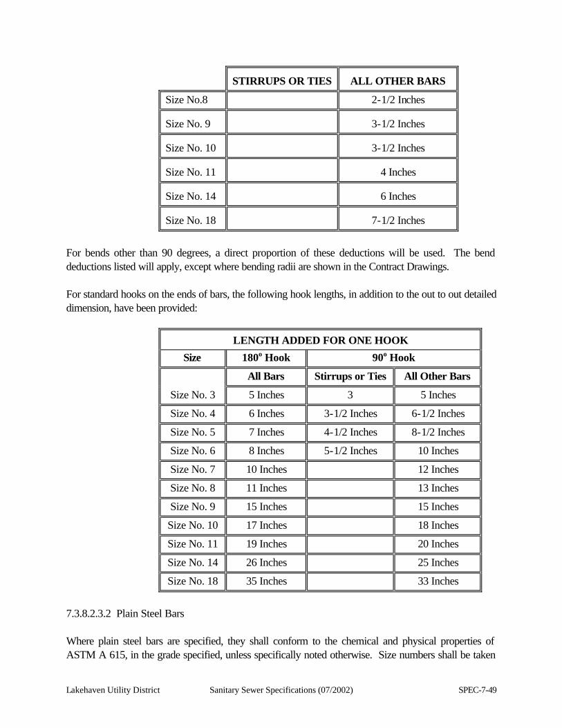
Lakehaven Utility District Sanitary Sewer Specifications (07/2002) SPEC-7-49
STIRRUPS OR TIES
ALL OTHER BARS
Size No.8 2-1/2 Inches Size No. 9
3-1/2 Inches
Size No. 10
3-1/2 Inches
Size No. 11
4 Inches
Size No. 14
6 Inches
Size No. 18
7-1/2 Inches
For bends other than 90 degrees, a direct proportion of these deductions will be used. The bend deductions listed will apply, except where bending radii are shown in the Contract Drawings. For standard hooks on the ends of bars, the following hook lengths, in addition to the out to out detailed dimension, have been provided:
LENGTH ADDED FOR ONE HOOK
Size 180o Hook 90o Hook
All Bars Stirrups or Ties All Other Bars
Size No. 3 5 Inches 3 5 Inches
Size No. 4 6 Inches 3-1/2 Inches 6-1/2 Inches
Size No. 5 7 Inches 4-1/2 Inches 8-1/2 Inches
Size No. 6 8 Inches 5-1/2 Inches 10 Inches
Size No. 7 10 Inches 12 Inches
Size No. 8 11 Inches 13 Inches
Size No. 9 15 Inches 15 Inches
Size No. 10 17 Inches 18 Inches
Size No. 11 19 Inches 20 Inches
Size No. 14 26 Inches 25 Inches
Size No. 18 35 Inches 33 Inches
7.3.8.2.3.2 Plain Steel Bars Where plain steel bars are specified, they shall conform to the chemical and physical properties of ASTM A 615, in the grade specified, unless specifically noted otherwise. Size numbers shall be taken
SPEC-7-50 Sanitary Sewer Specifications (07/2002) Lakehaven Utility District
to represent the diameter of the bar in 1/8-inch units, except where standard wire gauge sizes are shown in the Contract Drawings. 7.3.8.2.3.2.1 Dowel Bars (For Cement Concrete Pavement) Dowel bars shall be plain steel bars of the dimensions shown in the Contract Drawings. They shall conform to AASHTO M 183, Grade 60, except that the minimum yield point in Table 1 shall be modified to 35 ksi. 7.3.8.2.3.2.2 Spiral Ties Spiral ties shall be plain steel bars of the dimensions and grade shown in the Contract Drawings. Splices will be allowed in spiral ties. Splice details shall be as shown in the Contract Drawings. 7.3.8.2.3.3 Tie Bars. (For Cement Concrete Pavement) Tie bars shall conform to the requirements of the Standard Specifications for Deformed Billet-Steel Bars for Concrete Reinforcement, ASTM Designation A 615, Grade 60. The form of the deformed bar shall be subject to approval by the Engineer. Tie bars shall be free from rust, loose mill scale, dirt, grease or other defects affecting the strength or bond with the concrete. 7.3.8.2.3.4 Wire Mesh Wire mesh for concrete reinforcement shall conform to the requirements of the Standard Specifications for Welded Steel Wire Fabric for Concrete Reinforcement, ASTM Designation A 185. All wire mesh shall be of an approved kind and quality of manufacture. 7.3.8.2.3.5 Cold Drawn Wire Cold drawn wire shall conform to the requirements of ASTM Designation A 82, Cold Drawn Steel Wire for Concrete Reinforcement. 7.3.8.2.4 Concrete Curing Materials and Admixtures 7.3.8.2.4.1 Sheet Materials for Curing Cement Sheet materials for curing concrete shall meet the requirements of AASHTO Designation M 171, Sheet Materials for Curing Concrete, except that only white reflective type shall be used.
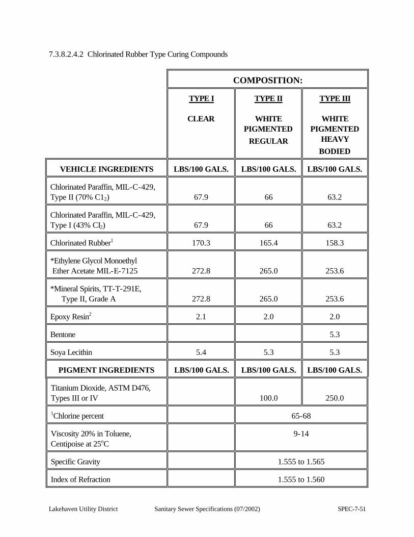
Lakehaven Utility District Sanitary Sewer Specifications (07/2002) SPEC-7-51
7.3.8.2.4.2 Chlorinated Rubber Type Curing Compounds
COMPOSITION:
TYPE I
CLEAR
TYPE II
WHITE
PIGMENTED REGULAR
TYPE III
WHITE
PIGMENTED HEAVY BODIED
VEHICLE INGREDIENTS
LBS/100 GALS.
LBS/100 GALS.
LBS/100 GALS.
Chlorinated Paraffin, MIL-C-429, Type II (70% C12)
67.9
66
63.2 Chlorinated Paraffin, MIL-C-429, Type I (43% CI2)
67.9
66
63.2 Chlorinated Rubber1
170.3
165.4
158.3
*Ethylene Glycol Monoethyl Ether Acetate MIL-E-7125
272.8
265.0
253.6 *Mineral Spirits, TT-T-291E,
Type II, Grade A
272.8
265.0
253.6 Epoxy Resin2
2.1
2.0
2.0
Bentone
5.3
Soya Lecithin
5.4
5.3
5.3
PIGMENT INGREDIENTS
LBS/100 GALS.
LBS/100 GALS.
LBS/100 GALS.
Titanium Dioxide, ASTM D476, Types III or IV
100.0
250.0 1Chlorine percent
65-68
Viscosity 20% in Toluene, Centipoise at 25oC
9-14
Specific Gravity
1.555 to 1.565
Index of Refraction
1.555 to 1.560
SPEC-7-52 Sanitary Sewer Specifications (07/2002) Lakehaven Utility District
COMPOSITION:
*A solvent blend may be substituted for the solvents in the formulation provided:
1. The solvent blend shall have a flash point of 70 degrees Fahrenheit tag open cup, minimum.
2. The finished curing compound shall conform to the requirements in this section for "characteristics of finished material" of said compound with the exception that appropriate deviations will be permitted in properties affected by the density of the solvent.
3. All containers in which modified curing compound is shipped shall be marked "MODIFIED". A 25 percent concentration in toluene shall show no haziness or turbidity, and when stored for one (1) week at 77 degrees Fahrenheit shall not corrode the tin plate in a covered tin-coated can.
2Liquid, color 5 max. (Gardner), Viscosity 100-160 poises at 25 degrees C, epoxide. At the discretion of the manufacturer, an anti-settling agent other than the specified soya lecithin may be used to ensure against caking and excessive settling of the pigment in the package. The total amount of anti-settling agent used shall not exceed 6.0 pounds per 100 gallons of the concrete curing compound. There shall be no caking or excessive settling of the pigment in the package that cannot be readily redispersed with a paddle.
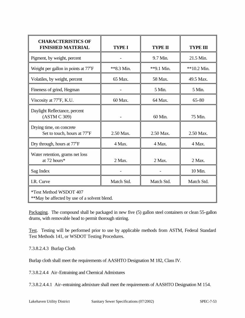
Lakehaven Utility District Sanitary Sewer Specifications (07/2002) SPEC-7-53
CHARACTERISTICS OF FINISHED MATERIAL
TYPE I
TYPE II
TYPE III Pigment, by weight, percent
-
9.7 Min.
21.5 Min.
Weight per gallon in points at 77oF
**8.3 Min.
**9.1 Min.
**10.2 Min.
Volatiles, by weight, percent
65 Max.
58 Max.
49.5 Max.
Fineness of grind, Hegman
-
5 Min.
5 Min.
Viscosity at 77oF, K.U.
60 Max.
64 Max.
65-80
Daylight Reflectance, percent
(ASTM C 309)
-
60 Min.
75 Min. Drying time, on concrete
Set to touch, hours at 77oF
2.50 Max.
2.50 Max.
2.50 Max. Dry through, hours at 77oF
4 Max.
4 Max.
4 Max.
Water retention, grams net loss
at 72 hours*
2 Max.
2 Max.
2 Max. Sag Index
-
-
10 Min.
I.R. Curve
Match Std.
Match Std.
Match Std.
*Test Method WSDOT 407 **May be affected by use of a solvent blend.
Packaging. The compound shall be packaged in new five (5) gallon steel containers or clean 55-gallon drums, with removable head to permit thorough stirring. Test. Testing will be performed prior to use by applicable methods from ASTM, Federal Standard Test Methods 141, or WSDOT Testing Procedures. 7.3.8.2.4.3 Burlap Cloth Burlap cloth shall meet the requirements of AASHTO Designation M 182, Class IV. 7.3.8.2.4.4 Air-Entraining and Chemical Admixtures 7.3.8.2.4.4.1 Air-entraining admixture shall meet the requirements of AASHTO Designation M 154.
SPEC-7-54 Sanitary Sewer Specifications (07/2002) Lakehaven Utility District
7.3.8.2.4.4.1.1 Acceptance will be on the basis of certified test reports, furnished by the manufacturer, indicating that the material meets the above specification. 7.3.8.2.4.4.1.2 If required by the Engineer, the air-entraining admixture shall be sampled and analyzed by an independent testing laboratory before use. 7.3.8.2.4.4.2 Chemical admixtures for concrete shall conform to the requirements of AASHTO Designation M 194, Type A, B, or D. Chemical admixtures containing more than one (1) percent chloride ion (C1-) by weight shall not be used. 7.3.8.2.4.4.2.1 Acceptance will be on the basis of certified test reports from the supplier, stating that the material meets the requirements of the above specification. 7.3.8.2.4.4.2.2 If required by the Engineer, the admixture shall be sampled and analyzed by an independent testing laboratory before use. 7.3.8.2.4.5 Air-Entraining and Chemical Admixtures for Precast Prestressed Concrete 7.3.8.2.4.5.1 Air-entraining admixture shall meet the requirements of AASHTO Designation M 154. 7.3.8.2.4.5.1.1 Acceptance will be on the basis of certified test reports, furnished by the manufacturer, indicating that the material meets the above specification. 7.3.8.2.4.5.1.2 If required by the Engineer, the air-entraining admixture shall be sampled and analyzed by an independent testing laboratory before use. 7.3.8.2.4.5.2 Chemical admixtures shall conform to the requirements of AASHTO Designation M 194, Type A, B, D, or F. Approval of specific admixture products shall be required as a part of the annual approval of prestressed fabricators. Chloride ion content of chemical admixtures shall not exceed one (1) percent by weight. 7.3.8.2.4.5.2.1 Acceptance will be on the basis of certified test reports from the supplier stating that the material meets the requirements of the above specification. 7.3.8.2.4.5.2.2 If required by the Engineer, the admixture shall be sampled and analyzed by an independent testing laboratory before use. 7.3.8.2.4.6 White Pigmented Curing Compound-Resin Base Resin base curing compound shall conform to the requirements of AASHTO M 148 for Type 2, Class B, white pigmented curing compound, except that the water retention of the liquid membrane-forming compound, when tested as specified in WSDOT Test Method 407, shall restrict the loss of water to not
Lakehaven Utility District Sanitary Sewer Specifications (07/2002) SPEC-7-55
more than 2.50 grams in 72 hours. 7.3.8.2.4.7 Fly Ash Fly ash shall conform to the requirements of ASTM C 618-80 Class C or F with optional chemical and physical requirements as set forth in Tables 1A and 2A and with a further limitation that the loss on ignition be a maximum of 1.5 percent.
7.3.8.2.5 Joint and Crack Sealing Materials 7.3.8.2.5.1 Premolded Joint Fillers 7.3.8.2.5.1.1 Asphalt Filler for Contraction and Longitudinal Joints in Concrete Pavements Premolded joint filler for use in contraction and longitudinal joints shall be 1/8-inch in thickness and shall consist of a suitable asphalt mastic encased in asphalt-saturated paper or asphalt-saturated felt. It shall be sufficiently rigid for easy installation in summer months and not too brittle for handling in cool weather. It shall meet the following test requirements: When a strip two (2) inches wide and 24 inches long is freely supported two (2) inches from each end and maintained at a temperature of 70 degrees Fahrenheit, it shall support a weight of 100 grams placed at the center of the strip without deflecting downward from a horizontal position more than two (2) inches within a period of five (5) minutes. 7.3.8.2.5.1.2 Premolded Joint Filler for Expansion Joints Premolded joint filler for use in expansion (through) joints shall conform to the specifications for "Reformed Expansion Joint Fillers for Concrete Paving and Structural Construction," ASTM Designation D 1751, except the requirement for water absorption which is deleted. 7.3.8.2.5.1.3 Elastomeric Sheet Elastomeric sheet shall be fabricated with nylon fabric from a high quality vulcanized elastomeric compound using polymerized chloroprene as the only basic elastomer. Elastomeric sheet shall be smooth, free from pinholes and surface blemishes; shall show no evidence of ply delamination; and shall meet the physical requirements shown in the table below. Methods and materials used to install the sheet to the required length shall be compatible and shall result in a leak proof sheet.
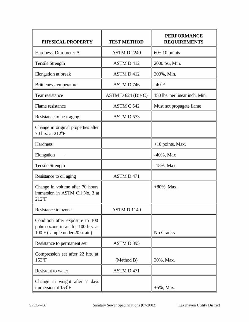
SPEC-7-56 Sanitary Sewer Specifications (07/2002) Lakehaven Utility District
PHYSICAL PROPERTY
TEST METHOD
PERFORMANCE REQUIREMENTS
Hardness, Durometer A
ASTM D 2240
60± 10 points
Tensile Strength
ASTM D 412
2000 psi, Min.
Elongation at break
ASTM D 412
300%, Min.
Brittleness temperature
ASTM D 746
-40oF
Tear resistance
ASTM D 624 (Die C)
150 lbs. per linear inch, Min.
Flame resistance
ASTM C 542
Must not propagate flame
Resistance to heat aging
ASTM D 573
Change in original properties after 70 hrs. at 212oF
Hardness
+10 points, Max.
Elongation .
-40%, Max
Tensile Strength
-15%, Max.
Resistance to oil aging
ASTM D 471
Change in volume after 70 hours immersion in ASTM Oil No. 3 at 212oF
+80%, Max.
Resistance to ozone
ASTM D 1149
Condition after exposure to 100 pphm ozone in air for 100 hrs. at 100 F (sample under 20 strain)
No Cracks
Resistance to permanent set
ASTM D 395
Compression set after 22 hrs. at 153oF
(Method B)
30%, Max.
Resistant to water
ASTM D 471
Change in weight after 7 days immersion at 153oF
+5%, Max.
Lakehaven Utility District Sanitary Sewer Specifications (07/2002) SPEC-7-57
7.3.8.2.5.1.4 Elastomeric Expansion Joint Seals Premolded elastomeric expansion joint seals shall conform to the requirements of AASHTO Designation M 220 and shall be formed by an extrusion process, with uniform dimensions and smooth exterior surfaces. The cross-section of the seal shall be shaped to allow adequate compressed width of the seal, as approved by the Engineer. 7.3.8.2.5.2 Joint Sealants 7.3.8.2.5.2.1 Joint Sealants for Sawed Contraction Joints Joint sealants for sawed contraction joints shall meet the requirements of one of the following: (1) AASHTO Designation M 173, Concrete Joint Sealer, Hot Poured Elastic Type, or (2) ASTM Designation D 1850, Concrete Joint Sealer, Cold Application Type; except that the test for evaluation of the bond requirements in the above specifications shall be in accordance with the bond test methods referred to in Section 7.3.8.2.5.2.2. Unless otherwise stated in the Contract Special Provisions, the Contractor will have the option of using either of the above two types. 7.3.8.2.5.2.2 Poured Rubber Joint Sealer The physical properties of the joint sealer, when mixed in accordance with the manufacturer's recommendations, shall be as follows:
(a) Color: Gray or black.
* (b) Viscosity: Must be pourable and self-leveling at 50 degrees Fahrenheit.
* (c) Application Life: Not less than 3 hours at 72 F degrees and 50 percent Relative Humidity.
(d) Set to Touch: Not more than 24 hours at 72 degrees Fahrenheit and 50 percent Relative Humidity.
(e) Curing Time: Not more than 96 hours at 72 degrees Fahrenheit and 50 percent Relative Humidity.
(f) Non-Volatile Content: Not less than 92 percent.
(g) Hardness Rating (Durometer "Shore A"): 5-35.
(h) Resiliency: Not less than 80 percent.
(i) Bond test methods shall be in accordance with WSDOT Test Method No. 412.
* Viscosity and application life may be waived providing the material is mixed and placed by a pump and mixer approved by the Engineer.
SPEC-7-58 Sanitary Sewer Specifications (07/2002) Lakehaven Utility District
Suitable primer, if required by the manufacturer, shall be furnished with each joint sealer. The primer shall be suitable for brush or spray application at 50 degrees Fahrenheit or higher and shall cure sufficiently at 50 degrees Fahrenheit to pour the joint within 24 hours. It shall be considered as an integral part of the sealer system. Any failure of the sealer in the test described herein, attributable to the primer, shall be grounds for rejection or re-testing of the sealer. Acceptance of joint sealing compound for use on a project shall be on the basis of laboratory tests of samples representative of each batch of material to be used on the job. A period of at least two (2) weeks shall be allowed for completion of tests. Each container of the compound shall be clearly identified as to batch number. 7.3.8.2.5.3 Cement Grout Grout for Class 2 finish shall consist of one (1) part Portland Cement, 1-1/2 parts fine sand (by weight) and water to a consistency of thick cream. The amount of water shall be only that needed to make the mix workable for the intended use. The cement shall be a mixture of white and gray cements as may be required to make a grout that when cured 28 days will match the adjacent concrete. Prepare several trial batches and make test samples in an inconspicuous location for review by the Engineer. When a mix has been selected for color match, batch all grout by weight in accordance with the formula for the selected mix. All other conditions for Portland Cement are as set forth in Section 7.3.8 of the specifications. 7.3.8.3 Construction Requirements 7.3.8.3.1 The restoration of cement concrete pavement shall be accomplished by patching the trench area as shown on the Contract Drawings for pavement restoration section for cement concrete. The patch shall conform to the grade existing prior to construction and shall provide a smooth, continuous restoration of the pavement surface. 7.3.8.3.2 Proportioning Materials Concrete for pavement shall be classified according to the age at which the pavement is designed to be put into use as hereinafter set forth. The standard paving mix is 14-day. The amount of cement (cement factor) for a cubic yard of concrete for each design age shall be not less than designated in the table below. Note that the cement factor is defined as the amount of cement per cubic yard of mix, determined in accordance with WSDOT Test Method No. 806. An approved air-entraining admixture shall be added to the materials to produce an air content of 5 ± 1-1/2 percent in the plastic concrete on the roadway in front of the spreader or slip-form paver. The Engineer will determine the percentage to be used. The Contract Drawings will show the design age and the standard paving section. The standard paving section is defined as that thickness of pavement that would be used with the standard 14-day paving
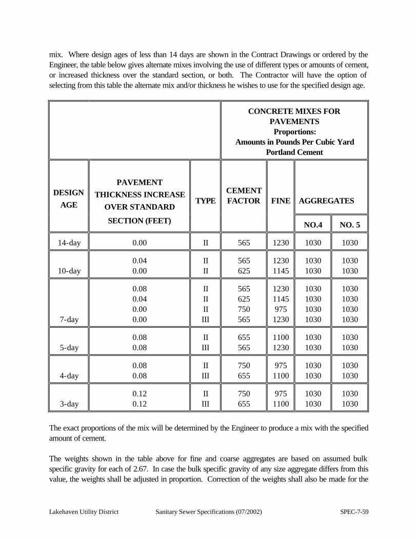
Lakehaven Utility District Sanitary Sewer Specifications (07/2002) SPEC-7-59
mix. Where design ages of less than 14 days are shown in the Contract Drawings or ordered by the Engineer, the table below gives alternate mixes involving the use of different types or amounts of cement, or increased thickness over the standard section, or both. The Contractor will have the option of selecting from this table the alternate mix and/or thickness he wishes to use for the specified design age.
CONCRETE MIXES FOR
PAVEMENTS Proportions:
Amounts in Pounds Per Cubic Yard Portland Cement
DESIGN AGE
PAVEMENT THICKNESS INCREASE
OVER STANDARD
TYPE
CEMENT FACTOR
FINE
AGGREGATES
SECTION (FEET)
NO.4
NO. 5
14-day
0.00
II
565
1230
1030
1030
10-day
0.04 0.00
II II
565 625
1230 1145
1030 1030
1030 1030
7-day
0.08 0.04 0.00 0.00
II II II III
565 625 750 565
1230 1145 975 1230
1030 1030 1030 1030
1030 1030 1030 1030
5-day
0.08 0.08
II III
655 565
1100 1230
1030 1030
1030 1030
4-day
0.08 0.08
II III
750 655
975 1100
1030 1030
1030 1030
3-day
0.12 0.12
II III
750 655
975 1100
1030 1030
1030 1030
The exact proportions of the mix will be determined by the Engineer to produce a mix with the specified amount of cement. The weights shown in the table above for fine and coarse aggregates are based on assumed bulk specific gravity for each of 2.67. In case the bulk specific gravity of any size aggregate differs from this value, the weights shall be adjusted in proportion. Correction of the weights shall also be made for the
SPEC-7-60 Sanitary Sewer Specifications (07/2002) Lakehaven Utility District
quantity of water held by the aggregate at the time of weighing.
Lakehaven Utility District Sanitary Sewer Specifications (07/2002) SPEC-7-61
The Contractor may, with the approval of the Engineer, blend the coarse aggregate from sizes other than the sizes given in the table above provided that: (a) The resulting coarse aggregate meets all requirements for No. 2 aggregate;
(b) Not less than 25 percent of the blend is from any size;
(c) Grading for the proposed sizes and their proportions in the blend are furnished to the Engineer before production of the aggregate, except from commercial sources, in which case this information must be submitted and approved before proportioning and mixing the concrete for this project.
When ordered by the Engineer, and when no provision is made in the contract for payment for alternate design ages, payment for additional costs to the Contractor for the alternate design ages ordered by the Engineer will be based on invoice differential for Type III or the additional Type II or Type III cement used. The additional thickness of pavement required will be paid at a rate based on square yardage per 0.01-foot of additional thickness, and shall be full payment for the extra excavation and concrete required for constructing the increased depth of pavement. Alternate design age pavements constructed by the Contractor for his/her convenience shall be at no additional cost to the Owner. Unfinished cement concrete pavement shall be the standard 14-day design age mix, except the asphalt concrete overlay may be constructed after seven (7) days of curing. The pavement may be opened to traffic upon completion of the construction of the asphalt pavement; otherwise, the Contractor shall protect the unfinished concrete pavement from traffic for the full 14 days. 7.3.8.3.3 Consistency The materials shall be mixed with sufficient water to produce a stiff concrete that will hold its shape when deposited upon the subgrade. Concrete placed during wet weather must be mixed with sufficient water to produce a very stiff mixture. The consistency shall be such that separation of the mortar from the coarse aggregate will not occur in handling. As a guide for determining the amount of water required for proper consistency of concrete, the Engineer may use the Method of Test for Slump of Portland Cement Concrete, WSDOT Test Method No. 804. Ordinarily, the slump for paving concrete shall be 1-1/2 ± 1/4 inches, when measured with the slump cone, except that when hand compacting and finishing is permitted, the slump shall not exceed two (2) inches. The amount of water may be varied by direction of the Engineer to secure the desired workability of the concrete and to prevent honeycombing and rock pockets.
SPEC-7-62 Sanitary Sewer Specifications (07/2002) Lakehaven Utility District
7.3.8.3.4 Equipment Equipment and tools necessary for handling materials and performing all parts of the work shall be approved by the Engineer as to design, capacity, and mechanical condition. The equipment shall be at the job site sufficiently ahead of the start of paving operations to be examined thoroughly and approved. (a) Batching plant and equipment.
1. General. The batching plant shall include bins, weighing hoppers, and scales for the fine
aggregate and for each size of coarse aggregate. If cement is used in bulk, a bin, hopper, and separate scale for cement shall be included. The weighing hoppers shall be properly sealed and vented to preclude dusting during operation The batching plant shall be equipped with a suitable non-resettable batch counter, which will correctly indicate the number of batches proportioned.
2. Bins and hoppers. Bins with adequate separate compartments for fine aggregate and for each size of the coarse aggregate shall be provided in the batching plant.
3. Scales. Plant and truck scales shall meet the requirements of Section 1.09.2 of the Washington State Standard Specifications for Road and Bridge Construction, (WSDOT 1984).
4. Batching plants shall be equipped to proportion aggregates and bulk cement by means of automatic weighing devices of an approved type.
(b) Mixers.
1. General. Concrete may be mixed at a batching plant or, wholly or in part, in truck mixers. Each mixer shall have attached in a prominent place a manufacturer's plate showing the capacity of the drum in terms of volume of mixed concrete and the speed of rotation of the mixing drum or blades.
2. Batching plant. Mixing shall be in an approved mixer capable of combining the aggregates, cement, and water into a thoroughly mixed and uniform mass within the specified mixing period. The mixer shall be equipped with an approved timing device which will automatically lock the discharge lever when the drum has been charged and release it at the end of the mixing period. The device shall be equipped with a bell or other suitable warning device adjusted to give a clearly audible signal each time the lock is released.
Mixers shall be cleaned at suitable intervals. The pickup and throw over blades in the drum or drums shall be repaired or replaced when they are worn down 3/4-inch or more. The Contractor shall (1) have available at the job site a copy of the manufacturer's design, showing dimensions and arrangements of the blades in reference to original height and depth, or (2) provide permanent marks on the blade to show points of 3/4-inch wear from new conditions. Drilled holes 1/4-inch in diameter near each end and at midpoint of each blade are recommended.
3. Truck mixers and truck agitators. Truck mixers used for mixing and hauling concrete, and truck
Lakehaven Utility District Sanitary Sewer Specifications (07/2002) SPEC-7-63
agitators used for hauling plant mixed concrete, shall conform to the requirements of Section 7.3.8.2.1.1.6.
4. Non-agitator trucks. Bodies of non-agitating hauling equipment for concrete shall be smooth, mortar-tight, metal containers and shall be capable of discharging the concrete at a satisfactory controlled rate without segregation. If discharge of concrete is accomplished by tilting the body, the surface of the load shall be retarded by a suitable baffle. Covers shall be provided when needed for protection. Plant-mixed concrete may be transported in non-agitated vehicles, provided that the concrete is delivered to the site of the work and discharge is completed within 45 minutes after the introduction of mixing water to the cement and aggregates, and provided the concrete is in a workable condition when placed.
(c) Finishing equipment.
The concrete shall be placed with an approved slip-form paver designed to spread, consolidate, screen, and float-finish the freshly placed concrete in one (1) complete pass of the machine in such manner that a minimum of hand-finish will be necessary to provide a dense and homogeneous pavement in conformance with the Contract Specifications and Drawings. (d) Joint Sawing Equipment The Contractor shall provide approved power driven gang saws for sawing joints, adequate in number of units and power to complete the sawing at the required rate. The Contractor shall provide at least one (1) standby saw in good working order. An ample supply of saw blades shall be maintained at the site of the work at all times during sawing operations. The Contractor shall provide adequate artificial lighting facilities for night sawing. All of this equipment shall be on the job both before and continuously during concrete placement. Sawing equipment shall be available immediately and continuously upon call by the Engineer on a 24-hour basis, including Saturdays, Sundays and holidays. 7.3.8.3.5 Handling, Measuring, and Batching Materials The batch plant site, layout, equipment, and provisions for transporting material shall be such as to ensure a continuous supply of material to the work. (a) Measuring Materials.
1. Aggregates: The fine aggregate and each size of coarse aggregate shall be measured by weighing, the weight for the particular aggregates used being proportional to their respective bulk specific gravity. The weighting of each size of material shall be a separate and distinct operation. Correction shall be made for variations in weight of materials due to the moisture content.
SPEC-7-64 Sanitary Sewer Specifications (07/2002) Lakehaven Utility District
The equipment for weighing aggregates shall conform to the requirements of Section 1-09.2, (WSDOT/APWA, 1996).
2. Cement shall be weighed on scales meeting the requirements of Section 1-09.2, (WSDOT/APWA, 1996). Adequate provision shall be made to prevent loss of cement between the batch box and the mixer.
3. Water: The amount of water required for each batch shall be determined by the Engineer. Water may be measured either by volume or by weight. The accuracy of measuring the water shall be within a range of error of not over one (1) percent.
(b) Batching Materials. On all projects requiring more than 2,500 cubic yards of Portland cement concrete for paving, batching plants shall be equipped to proportion aggregates and cement by weight by means of automatic and interlocked proportioning devices of approved type. 7.3.8.3.6 Mixing Concrete The concrete may be mixed in a batching plant or in truck mixers. The mixer shall be of an approved type and capacity. Mixing time shall be measured from the time all materials are in the drum. Ready-mixed concrete shall be mixed and delivered in accordance with the requirements of Section 7.3.8.2.1.1.6 of these specifications. When mixed in a batching plant, the mixing time shall not be less than 50 seconds nor more than 90 seconds. The mixer shall be operated at a drum speed as shown on the manufacturer's name plate on the mixer. Any concrete mixed less than the specified time shall be discarded and disposed of by the Contractor at his/her expense. The volume of concrete mixed per batch shall not exceed the mixer's nominal capacity in cubic feet, as shown on the manufacturer's standard rating plate on the mixer. Each concrete mixing machine shall be equipped with a device for counting automatically the number of batches mixed during the day's operation. All elements of a batch shall be simultaneously and continuously fed to the mixer to assure uniform distribution of cement, water, aggregates and admixtures. Retempering concrete by adding water or by other means will not be permitted. Admixtures for increasing the workability or for accelerating the set will be permitted only when specified or approved by the Engineer.
Lakehaven Utility District Sanitary Sewer Specifications (07/2002) SPEC-7-65
7.3.8.3.6.1 Limitations of Mixing Concrete shall not be mixed, placed or finished when the natural light is inadequate, as determined by the Engineer, unless an adequate and approved artificial lighting system is operated. Mixing and placing concrete shall be discontinued when a descending air temperature, in the shade away from artificial heat, reaches 40 degrees Fahrenheit and not be resumed until an ascending air temperature, in the shade and away from artificial heat, reaches 35 degrees Fahrenheit, unless authorized in writing by the Engineer. When mixing and placing is authorized during cold weather, the aggregates may be heated by either steam or dry heat prior to being placed in the mixer. The apparatus used shall heat the mass uniformly and shall be so arranged as to preclude the possible occurrence of overheated areas which might injure the materials. Unless otherwise authorized, the temperature of the mixed concrete shall be not less than 50 degrees Fahrenheit and not more than 90 degrees Fahrenheit at the time of discharge into the hauling conveyance. No concrete shall be mixed with frozen aggregates. 7.3.8.3.7 Subgrade The subgrade shall be constructed in accordance with the Contract Drawings and these specifications. The subgrade shall be prepared and compacted a sufficient distance beyond each edge of the area which is to receive concrete pavement in order to accommodate the slip-form equipment without visible distortion. Concrete shall not be placed on a frozen subgrade, nor during heavy rainfall. The subgrade shall be thoroughly saturated with water from 12 to 48 hours before the concrete is to be placed and shall be wet for a depth of at least eight (8) inches and for such additional depth as may be required to prevent hair-checking in the concrete. 7.3.8.3.8 Placing, Spreading and Compacting Concrete The concrete shall be distributed uniformly into final position by the slip-form paver without delay. The alignment and elevation of the paver shall be regulated from outside reference lines established for this purpose. The paver shall vibrate the concrete for the full width and depth of the strip of pavement being placed and the vibration shall be adequate to provide a consistency of concrete that will stand normal to the surface with sharp well defined edges. The sliding forms shall be rigidly held together laterally to prevent spreading of the forms. The plastic concrete shall be effectively consolidated by internal vibration with transverse vibrating units for the full width of pavement and/or a series of equally spaced longitudinal vibrating units. The space from the outer edge of the outer longitudinal unit shall not exceed nine (9) inches. The spacing of internal units shall be uniform and not exceed 18 inches.
SPEC-7-66 Sanitary Sewer Specifications (07/2002) Lakehaven Utility District
The term internal vibration specified herein means vibration by vibrating units located within the specified thickness of pavement section and a minimum distance equal to the pavement thickness ahead of the screen. The rate of vibration of each vibrating unit shall be not less than 7,500 vibrations per minute, and the amplitude of vibration shall be sufficient to be perceptible on the surface of the concrete along the entire length of the vibrating unit and for a distance of at least one (1) foot therefrom. The frequency of vibration or amplitude shall be varied proportionately with the rate of travel to result in a uniform density and air content. The paving machine shall be equipped with a tachometer or other suitable device for measuring and indicating the actual frequency of vibrations. The provisions relating to the frequency and amplitude of internal vibration are to be considered the minimum requirements and are intended to assure adequate density in the hardened concrete. Referee testing of hardened concrete will be performed by cutting cores from the finished pavement after a minimum of 24 hours of curing when, in the opinion of the Engineer, conditions will permit, and a determination of the density will be made therefrom. Density determination shall be made based on the water content of the core as taken. WSDOT Test Method 810 shall be used for the determination of core density. The density determined in this manner shall meet the following requirements when compared with the density of plastic concrete as determined by WSDOT Test Method No. 806: The average density of the cores shall be at last 98 percent of the plastic concrete density, with no cores having a density of less than 97.5 percent of the plastic concrete density. Failure to meet the above requirement will be considered as evidence that the minimum requirements for vibration are inadequate for the job conditions, and additional vibrating units or other means of increasing the effect of vibration shall be employed so that the density of the hardened concrete, as indicated by further referee testing, shall conform to the above listed requirements. The concrete shall be held at a uniform consistency, having a slump as specified in Section 7.3.8.3.3 of these specifications. The slip-form paver shall be operated with as nearly a continuous forward movement as possible and all operations of mixing, delivering and spreading concrete shall be so coordinated as to provide uniform progress, with stopping and starting of the paver held to a minimum. If, for any reason, it is necessary to stop the forward movement of the paver, the vibratory and tamping elements shall also be stopped immediately. No tractive force shall be applied to the machine, except that which is controlled from the machine. When concrete is being placed adjacent to an existing pavement, that part of the equipment which is supported on the existing pavement shall be equipped with protective pads on crawler tracks or rubber-tired wheels on which the bearing surface is offset to run a sufficient distance from the edge of the pavement to avoid breaking the pavement edge.
Lakehaven Utility District Sanitary Sewer Specifications (07/2002) SPEC-7-67
With the approval of the Engineer, projects involving small quantities of cement concrete pavement, irregular areas and at locations inaccessible to slip-form paving equipment, concrete pavement may be placed between stationary side forms, compacted to the specified density by suitable means, finished to the required surface smoothness by the hand-float method or other suitable means, and finally scored transversely with a comb. The finished surface shall conform to the requirements outlined in Section 7.3.8.3.12 of these specifications. 7.3.8.3.9 Joints Joints in cement concrete pavement will be designated as longitudinal and transverse contraction joints and longitudinal and transverse construction joints, and shall be constructed as shown in the Contract Drawings and in accordance with the following provisions: All contraction joints shall be constructed at the locations, intervals and depths shown in the current WSDOT/APWA Standard Plans. The faces of all joints shall be constructed perpendicular to the surface of the cement concrete pavement. 7.3.8.3.9.1 Contraction Joints Transverse contraction joints shall be sawed with a suitable power-driven gang saw incorporating at least four (4) separate blades. Commencement of sawing transverse contraction joints will be dependent upon the setting time of the concrete and shall be done at the earliest possible time following placement of the concrete consistent with being able to saw without tearing or raveling the adjacent concrete excessively. Initial or control transverse contraction joints shall be sawed at intervals of 92 feet, or at such other interval which will most effectively minimize the possibility of uncontrolled cracking with a minimum number of initial contraction joints. The remaining contraction joints shall be sawed, normally, between 24 and 48 hours after the placement of the concrete pavement, as shown in the Contract Drawings. When cool weather results in retarded setting of the concrete, the sawing of joints may be deferred only for the time sufficient to preclude excessive tearing of the concrete adjacent to the joint. The concrete saw shall be powered adequately to perform the required cutting. It shall cut a uniform groove to the required depth and not less than 1/8-inch nor more than 1/4-inch in width. The Contractor will be expected to so arrange his/her scheduling of sawing joints, including initial sawing at the required intervals, so that every possible effort is made to control cracking by the use of judiciously spaced and timed sawed joints. In the event random cracks occur, they shall be repaired in accordance with Section 7.3.8.3.22 of these specifications. The placement of cork or other type of preformed fillers in the joint, followed by sawing the filler after the concrete has set, will not be allowed. Longitudinal contraction joints shall be sawed to the required depth as soon as practicable after the
SPEC-7-68 Sanitary Sewer Specifications (07/2002) Lakehaven Utility District
initial control transverse contraction joints are completed and not later than three (3) days after the concrete pavement has been placed. When sawing is done within 48 hours after the concrete has been placed, water trucks and all equipment, other than the saw, shall be kept off the pavement. Any damage to the curing material during the sawing operations shall be repaired immediately after the sawing is completed. Formed transverse contraction joints shall be installed where and as directed by the Engineer, if necessary, to prevent uncontrolled transverse cracks from occurring before the pavement can be sawed. When formed joints are installed, a mechanical vibratory device shall be used to cut the groove to receive the joint filler. A hand-operated tool will not be permitted. Formed contraction joints shall be constructed as specified hereinafter. At the option of the Contractor, instead of sawing as provided above, longitudinal contraction joints at traffic lane lines in multi-lane monolithic concrete pavement may be formed by placing a continuous strip of plastic or other material which will not react adversely with the chemical constituents of the concrete. The joint insert material shall be of such width and character that when placed vertically in the concrete it will not bond with the concrete and will form an effective weakened plane joint with a minimum depth of 1/4 of pavement depth plus 1/2-inch. The joint material shall be inserted with a mechanical device that places the material in a continuous strip, except where intervening structures break the continuity of paving. Splices in the joint material will be permitted providing they are effective in maintaining the continuity of the joint material as placed. The joint material shall be placed in such manner that the top of the strip is not more than 0.01 foot below the finished surface of the concrete. The joint material shall not be deformed from a vertical position, either in the installation or in subsequent finishing operations performed on the concrete. The alignment of the finished joint shall be uniformly parallel with the centerline of the pavement and free of any local irregularity which exceeds 0.05-foot, measured with a ten (10) foot straightedge, except for normal curvature of centerline alignment. The mechanical installation device shall vibrate the concrete during placing the strip sufficiently to cause the concrete to flow evenly about the joint material, producing homogenous concrete free of segregation and rock pockets or voids. 7.3.8.3.9.2 Sealing Sawed Contraction Joints Sawed contraction joints shall be filled with a joint sealant filler conforming to the requirements of Section 7.3.8.2.5.2. Joints shall be thoroughly clean at the time of sealing and if the hot poured type is used, the joints shall be dry. Care shall be taken to avoid air pockets. The hot poured compound shall be applied in two (2) or more layers, if necessary. The cold poured compound shall be applied under sufficient pressure to fill the groove from bottom to top and to a point approximately 1/4-inch above the surface of the concrete. The joint filled with cold poured compound shall then be covered with a strip of non-absorptive paper at least twice as wide as the joint and the paper shall be left in place. If contraction joints are formed with plastic strips, sealing is not required.
Lakehaven Utility District Sanitary Sewer Specifications (07/2002) SPEC-7-69
7.3.8.3.9.3 Construction Joints When placing of concrete is discontinued for more than 45 minutes, a transverse construction joint shall be installed. Construction joints shall be as shown in the current WSDOT/APWA Standard Plans. 7.3.8.3.10 Reinforcing Bridge approach slabs shall be reinforced as shown in the Standard Plan, or as required by the Engineer. 7.3.8.3.11 Tie Bars and Dowel Bars Steel tie bars shall be placed at all longitudinal contraction and construction joints, in accordance with the requirements shown in the current WSDOT/APWA Standard Plans. Tie bars will not be required when constructing cement concrete pavement on a treated base surface. Tie bars shall be placed at longitudinal construction joints between lanes in such a manner that the individual bars are located at the required elevation and spacing as shown in the current WSDOT/APWA Standard Plans and in such a manner that the vertical edge of the concrete is not deformed or otherwise damaged during placement of the bars. Dowel bars will be required for the construction joint at the end of paving operations each day and shall be placed in accordance with the current WSDOT/APWA Standard Plans. 7.3.8.3.12 Finishing After the concrete has been given a preliminary finish by means of finishing devices incorporated in the slip-form paving equipment, the surface of the fresh concrete shall be checked by the Contractor with a straightedge device not less than ten (10) feet in length. High areas indicated by the straightedge device shall be removed by the hand-float method. Each successive check with the straightedge device shall lap the previous check path by at last 1/2 of the length of the straightedge. The requirements of this section may be waived if it is successfully demonstrated that other means will consistently produce a surface with a satisfactory profile index and meeting the ten (10) foot straightedge requirement specified in Section 7.3.8.3.13 of these specifications. Any edge slump of the pavement, exclusive of specified edging, in excess of 1/4-inch, shall be corrected before the concrete has hardened. If edge slump on any one (1) foot or greater length of hardened concrete exceeds one (1) inch, the entire panel between the transverse and longitudinal joints shall be removed and replaced with concrete true to the specified line, grade, and cross-section. High spots exceeding 1/4-inch shall be reduced by suitable grinding methods. Low spots exceeding 1/4-inch shall be filled with an approved epoxy-bonded grout in a manner directed by the Engineer.
SPEC-7-70 Sanitary Sewer Specifications (07/2002) Lakehaven Utility District
Before the concrete has taken its initial set, the edges of the pavement on each side of transverse expansion joints, formed joints, transverse construction joints, and emergency construction joints shall be worked with an approved tool and rounded to the radius required by the Contract Drawings. A well-defined and continuous radius shall be produced and a smooth, dense mortar finish obtained. The pavement shall be given a final finish surface by texturing with a comb perpendicular to the centerline of the pavement. The comb shall produce striations approximately 0.015-foot in depth at approximately 1/2-inch spacing in the fresh concrete. The actual nominal depths of the striations shall be determined in the field by the Engineer. The comb shall be operated mechanically either singly or in gangs, with several placed end to end. Finishing shall take place with the elements of the comb as nearly perpendicular to the concrete surface as is practicable, to eliminate the dragging of the mortar. If the striation equipment has not been previously approved, a test section shall be constructed prior to approval of the equipment. At the beginning and end of paving each day, the Contractor shall, with an approved stamp, indent the concrete surface near the right hand edge of the panel to indicate the date, month and year of placement. At approximate 500 foot intervals, where designated by the Engineer, the Contractor shall, with an approved stamp, indent the concrete surface near the right hand edge of the pavement to show the stationing of the roadway. 7.3.8.3.13 Surface Smoothness Not later than 5 P.M. of the day following the placing of the concrete, the pavement smoothness will be checked by the Engineer. Smoothness parallel to the centerline will be measured with a recording profilograph, from which the profile index will be determined in accordance with WSDOT Test Method 807. For the purpose of qualifying the equipment and methods used by the Contractor, a daily profile index will be computed. For pavement placed in a 12-foot width or less, the daily profile index will be the average of two (2) profiles made approximately three (3) feet from and parallel to each edge of the pavement. If the pavement is placed in a width greater than 12 feet, the daily profile index will be computed as the average of profiles made approximately three (3) feet from and parallel to each edge and at the approximate location of each planned longitudinal joint. The daily profile index of the finished pavement, thus determined, will be seven (7) inches per mile, or less. Only equipment and methods that consistently produce a finished surface meeting this requirement shall be used. Should the daily profile index exceed the rate of seven (7) inches per mile, the paving operations shall be discontinued until other methods or equipment are provided by the Contractor. Such revised methods and equipment shall again be discontinued if they do not produce a finished surface having a daily profile index of seven (7) inches per mile, or less. Operations shall not be resumed until the Engineer approves further changes in methods and equipment as proposed by the

Lakehaven Utility District Sanitary Sewer Specifications (07/2002) SPEC-7-71
Contractor.
SPEC-7-72 Sanitary Sewer Specifications (07/2002) Lakehaven Utility District
All areas representing high points having deviations in excess of 0.3-inch, as determined by procedures described in WSDOT Test Method 807, shall be reduced by abrasive means until such deviations do not exceed 0.3-inch, as determined by reruns of the profilograph. After reduction of all areas with high points in excess of 0.3-inch, the final acceptance of the pavement for smoothness parallel to the centerline will be based on profile indexes as measured by the profilograph along any line parallel to the edge of pavement. The acceptance profile indexes will be taken at not less than three (3) feet from the edge of pavement and each longitudinal joint and will not be averaged for acceptance purposes. High areas of individual profiles shall be reduced by abrasive means, so that the profile index will not exceed 0.7-inch in any 0.1 mile section. All high areas in excess of 0.1 inch shall be reduced to 0.0 inch prior to reducing any high points of 0.1 inch or less. When cement concrete pavement abuts bridges or pavement constructed under another contract, the finished pavement parallel to centerline within 15 feet of the abutting joint shall be uniform to a degree such that no variations greater than 1/8-inch are present when tested with a ten (10) foot straightedge. Smoothness perpendicular to the centerline will be measured with a ten (10) foot straightedge. The transverse slope of the finished pavement shall be uniform to a degree such that no variations greater than 1/4-inch are present when tested with a ten (10) foot long straightedge laid in a direction perpendicular to the centerline. Any areas that are in excess of this specified tolerance shall be corrected by abrasive means. 7.3.8.3.14 Curing Immediately after the finishing operations have been completed and as soon as marring of the concrete will not occur, the entire surface of the newly placed concrete shall be covered and cured in accordance with one of the following methods as the Contractor may elect. 7.3.8.3.14.1 Curing Period Regardless of the curing method used, as described herein, the Contractor shall maintain such curing protection and shall protect the pavement from damage from any cause for at least the length of time shown in the following table for the various mixes, or for a greater length of time, as directed by the Engineer.
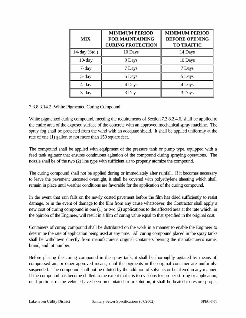
Lakehaven Utility District Sanitary Sewer Specifications (07/2002) SPEC-7-73
MIX
MINIMUM PERIOD FOR MAINTAINING
CURING PROTECTION
MINIMUM PERIOD BEFORE OPENING
TO TRAFFIC 14-day (Std.) 10 Days 14 Days
10-day 9 Days 10 Days
7-day 7 Days 7 Days
5-day 5 Days 5 Days
4-day 4 Days 4 Days
3-day 3 Days 3 Days
7.3.8.3.14.2 White Pigmented Curing Compound White pigmented curing compound, meeting the requirements of Section 7.3.8.2.4.6, shall be applied to the entire area of the exposed surface of the concrete with an approved mechanical spray machine. The spray fog shall be protected from the wind with an adequate shield. It shall be applied uniformly at the rate of one (1) gallon to not more than 150 square feet. The compound shall be applied with equipment of the pressure tank or pump type, equipped with a feed tank agitator that ensures continuous agitation of the compound during spraying operations. The nozzle shall be of the two (2) line type with sufficient air to properly atomize the compound. The curing compound shall not be applied during or immediately after rainfall. If it becomes necessary to leave the pavement uncoated overnight, it shall be covered with polyethylene sheeting which shall remain in place until weather conditions are favorable for the application of the curing compound. In the event that rain falls on the newly coated pavement before the film has dried sufficiently to resist damage, or in the event of damage to the film from any cause whatsoever, the Contractor shall apply a new coat of curing compound in one (1) or two (2) applications to the affected area at the rate which, in the opinion of the Engineer, will result in a film of curing value equal to that specified in the original coat. Containers of curing compound shall be distributed on the work in a manner to enable the Engineer to determine the rate of application being used at any time. All curing compound placed in the spray tanks shall be withdrawn directly from manufacturer's original containers bearing the manufacturer's name, brand, and lot number. Before placing the curing compound in the spray tank, it shall be thoroughly agitated by means of compressed air, or other approved means, until the pigments in the original container are uniformly suspended. The compound shall not be diluted by the addition of solvents or be altered in any manner. If the compound has become chilled to the extent that it is too viscous for proper stirring or application, or if portions of the vehicle have been precipitated from solution, it shall be heated to restore proper
SPEC-7-74 Sanitary Sewer Specifications (07/2002) Lakehaven Utility District
fluidity, but it shall not be heated above 100 degrees Fahrenheit. The curing compound shall be applied immediately after the concrete has been finished and after any surplus water that has collected on the surface has disappeared, or at such other time as is directed by the Engineer. If hair checking develops in the pavement before finishing is completed, the Engineer may order the application of the curing compound at an earlier stage, in which event any concrete cut from the surface in finishing operations shall be removed entirely from the pavement. If additional mortar is then needed to fill torn areas, it shall be obtained ahead of the spraying operations. All areas cut by finishing tools subsequent to the application of the curing compound shall immediately be given new applications at the rate specified above. The compound, after application, shall be protected by the Contractor from injury for the period of time specified above. All traffic, either by foot or otherwise, shall be considered as injurious to the film of the applied compound. The Contractor shall provide on the job a sufficient quantity of white polyethylene sheeting to cover all the pavement laid in three (3) hours of maximum operation. This sheeting shall be reserved exclusively for the protection of the pavement in case of rain or breakdown of the spray equipment used for applying the curing compound. The protective sheeting shall be placed over the pavement when ordered and in the manner directed by the Engineer. Areas from which it is impossible to exclude traffic shall be protected by a covering of sand or earth not less than one (1) foot in thickness or by other suitable and effective means. The protective covering shall be placed no earlier than 24 hours after application of the compound. The Contractor shall assume all liabilities for and protect the District from any damages or claims arising from the use of materials or processes described herein. 7.3.8.3.14.3 White Polyethylene Sheeting The sheeting shall be placed over the pavement immediately after finishing operations are completed, or at a time ordered by the Engineer. The sheeting shall be laid so that individual sheets overlap at least two (2) feet, and the lapped areas shall be held in close contact with the pavement by weighting with earth or boards in such a manner as to prevent movement by the wind. The sheeting shall extend downward to cover the edges of the pavement and shall be secured to the subgrade with a continuous bank of earth or surfacing material. Any holes occurring in the sheeting shall be patched immediately to the satisfaction of the Engineer. The sheeting shall be maintained against injury and remain in place the minimum period of time as specified above.
Lakehaven Utility District Sanitary Sewer Specifications (07/2002) SPEC-7-75
7.3.8.3.15 Cold Weather Work To provide for cold weather curing and when ordered in writing by the Engineer, the Contractor shall provide a sufficient supply of straw, hay, grass, earth, blankets, or other suitable blanketing material on the project. When the temperature may be expected to reach the freezing point during the day or night and the pavement has not cured for 50 percent of the time specified in Section 7.3.8.3.14.1, the material so provided shall be immediately spread over any such pavement to a sufficient depth to prevent freezing of the concrete. The Contractor shall be responsible for the quality and strength of the concrete thus cured. Any concrete injured by frost action or freezing shall be removed and replaced at the Contractor's expense in accordance with these specifications. 7.3.8.3.16 Concrete Pavement Construction in Adjacent Lanes Unless otherwise shown in the Contract Drawings or in the Contract Special Provisions, the pavement shall be constructed in multiple lanes; that is, two (2) or more adjacent lanes paved in a single operation. Concrete shall not be placed in succeeding lanes until that in adjacent lanes has acquired a modulus of rupture of not less than 500 pounds per square inch as measured by test beams cast at the time the concrete is placed. The Contractor shall replace at his expense any panels on the new pavement that are cracked or broken as a result of his/her operations. 7.3.8.3.17 Protection of Pavement The Contractor shall protect the pavement and its appurtenances from any damage. Protection shall include watchmen to direct traffic and the erection and maintenance of warning signs, lights, barricades, temporary take-down bridges across the pavement with adequate approaches, and whatever other means may be necessary to accommodate local traffic and to protect the pavement during curing period or until opened to traffic as directed by the Engineer. Standard portable barricades (first or outside barricades), as shown in the Contract Drawings, shall be placed in accordance with the approved traffic control plan. Approval shall be from the governmental agency having jurisdiction. Also, a continuous barricade of the design shown in the plans shall be constructed and maintained along the edge of the pavement being constructed and adjacent to the portion of the roadway used for traffic. The barricades shall be left in place until the new pavement is opened to traffic and shall then be removed by the Contractor. Any damage to the pavement occurring prior to final acceptance shall be replaced or repaired in accordance with Section 7.3.8.3.22.
SPEC-7-76 Sanitary Sewer Specifications (07/2002) Lakehaven Utility District
7.3.8.3.18 Opening to Traffic The Engineer will decide when the pavement shall be opened to traffic. Prior to opening to traffic, the pavement shall be cleaned. 7.3.8.3.19 Cement Concrete Driveways Concrete driveways shall be constructed at the locations shown in the Contract Drawings or as directed by the Engineer and in accordance with the current WSDOT/APWA Standard Plans. The provisions of Section 7.3.8 shall pertain in the construction of concrete driveways except for the following: Forms: Wood side forms for straight sections shall be not less than three (3) inches (commercial) in thickness, surfaced and shall extend the full depth of the driveway. Placing, Compacting, and Finishing: Concrete may be placed, compacted, and finished using hand methods. The Engineer shall approve the tools required for these operations. 7.3.8.3.20 Unfinished Cement Concrete Pavement (Concrete Encasement) Unfinished cement concrete pavement shall conform to all requirements of Section 7.3.8, with the following exceptions: (1) Side forms are to be used in accordance with Section 7.3.8.3.21. If approved by the Engineer, the
Contractor may eliminate the side forms and place the concrete by use of some type of slip-form machine that will enable the placement of the unfinished concrete pavement with reasonably square edges.
(2) Compacting and finishing of the concrete may be carried out by hand methods, using approved hand tools.
(3) The surface smoothness will be such that no point on the surface will be more than 1/4-inch from the lower edge of a ten (10) foot straightedge laid in all directions from the crown point.
(4) Contraction joints as described in Section 7.3.8.3.9, and as shown on the current WSDOT/APWA Standard Plans, will not be required; however, the Contractor shall score the surface to create a weakened plane one (1) inch deep, matching transverse joints on adjacent concrete pavement and at 15 foot intervals transversely on other areas, or provide approved alternates.
(5) Liquid curing compounds that leave a waxy film on the concrete shall not be used for curing unfinished cement concrete pavement. If cured with a liquid curing compound, it shall meet the requirements of Section 7.3.8.2.4.2 for the clear type and the rate of coverage shall be at least one (1) gallon per 125 square feet; or emulsified asphalt CSS-1 or CRS-1 meeting the requirements of Section 7.3.6.5 applied at a rate between 0.15 gallon and 0.25 gallon per square yard of surface.
Lakehaven Utility District Sanitary Sewer Specifications (07/2002) SPEC-7-77
7.3.8.3.21 Side Forms When specified or approved by the Engineer, side forms may be used for pavement construction. Side forms shall have a height of not less than the specified depth of pavement and shall be of ample strength to resist deformation. They shall be provided with adequate devices for secure setting so that when in place they shall withstand, without visible springing or settlement, the weight, impact and vibration of the finishing machines. The forms shall be free from warps, bends or kinks. Forms shall be drilled in advance of being placed to line and grade to accommodate tie bars where these are specified. Forms shall remain in place at least 12 hours after the concrete has been placed and shall be cleaned and oiled each time they are used. Curing compound shall be applied to the concrete immediately after the forms are removed. The alignment and grade elevations of the forms shall be checked and the necessary corrections made by the Contractor immediately before placing the concrete. When any form has been disturbed or any subgrade thereunder has become unstable, the form shall be reset and rechecked. 7.3.8.3.22 Repair of Defective Pavement Slabs Broken slabs, random cracks, nonworking contraction joints near cracks, and spalls along joints and cracks shall be replaced or repaired as specified hereinafter at no cost to the District and shall be accomplished prior to completion of joint sealing. Pavement slabs containing multiple cracks through the full depth of the slab, separating the slab into three (3) or more parts, shall be entirely removed and replaced. Pavement slabs containing a single diagonal crack intersecting the transverse and longitudinal joints within 1/3 of the width and length of the slab from the corner shall be repaired by removing and replacing the smaller portion of the slab. Repairs of broken slabs shall be made as directed. Random cracks penetrating the full depth of the pavement shall be grooved and sealed. The top of the crack shall be grooved to a minimum depth of 3/4-inch and to a width not less than 3/8-inch nor more than 5/8-inch by means of an approved grooving machine. The grooving machine shall be capable of following closely the path of the crack and of widening the top of the crack to the required section without spalling or otherwise damaging the concrete. Loose and fractured concrete shall be removed and the groove shall be thoroughly cleaned and sealed. Random cracks that are tight and that do not penetrate the full depth of the pavement shall be left undisturbed. When necessary, the depth of crack penetration shall be determined by inspection of cores drilled at the Contractor's expense. When a transverse random crack terminates in or crosses a transverse contraction joint, the uncracked

SPEC-7-78 Sanitary Sewer Specifications (07/2002) Lakehaven Utility District
portion of the joint shall be filled with epoxy-resin mortar or grout and the crack shall be routed and sealed. When a transverse random crack approximately parallels the planned contraction joint and is within a distance of five (5) feet from a contraction joint in the pavement, the crack shall be routed and sealed, and the joint shall be filled with epoxy-resin grout or mortar. When a transverse random crack is more than five (5) feet from the nearest contraction joint in the pavement, both the joint and the crack shall be sealed. Joints to be filled with epoxy-resin mortar or grout shall be thoroughly cleaned. Spalls shall be repaired by making a saw cut at least one (1) inch outside the spalled area and to a minimum depth of two (2) inches. When the spalled area abuts a joint, the saw cut shall be made to a depth of two (2) inches or 1/6 the slab thickness, whichever is greater. The concrete between the saw cut and the joint or primary crack shall be chipped out to solid concrete. The cavity thus formed shall be thoroughly cleaned of all loose material. A prime coat of epoxy-resin binder shall be applied to the dry, cleaned surface of all sides of the cavity, except the joint or primary crack face. The prime coat shall be applied by scrubbing prime coat material into the surface with a stiff-bristle brush. Placement of Portland cement concrete or epoxy-resin concrete or mortar shall immediately follow the application of the prime coat, as directed. If the spalled area to be patched abuts a working joint or a working crack, which penetrates the full depth of a slab, an insert or other bond-breaking medium shall be used to maintain working joints or cracks during the repair work. 7.3.8.4 Pavement Thickness It is the intent of these specifications that cement concrete pavement shall be constructed in accordance with the thickness requirements of the Contract Drawings and Specifications. Tolerances allowed for subgrade construction and other provisions that may affect thickness shall not be construed to modify such thickness requirements. For the purposes of these specifications, a primary unit of pavement is defined as the area of pavement placed in each day's paving operations. Within such primary unit of pavement, there may be an area or areas that are deficient in thickness by more than 0.05-foot. This deficient area, or areas, will be defined as a secondary unit or units. If secondary units are found to exist, the primary unit area will be reduced by the secondary unit area included therein. At a time determined by the Engineer, thickness measurements will be made in each primary unit of pavement at the minimum rate of one (1) measurement for each 2,500 square yards of pavement, or fraction thereof. The exact location and number of thickness measurements within each primary unit, both longitudinally and transversely, will be determined by the Engineer. In general, thickness measurements will be made at uniform intervals throughout each primary unit of pavement. If thickness deficiencies greater than 0.05-foot are found to exist, supplemental thickness measurements will be made in accordance with Section 7.3.8.4.2 herein. Pavement thickness variations, if any, from the thickness requirements of the Contract Drawings and Specifications will be determined by comparing the actual thickness measurement with the thickness specified at the location where the measurement was made. Such variation will be determined to the nearest 0.01-foot as either excess or deficient thickness.
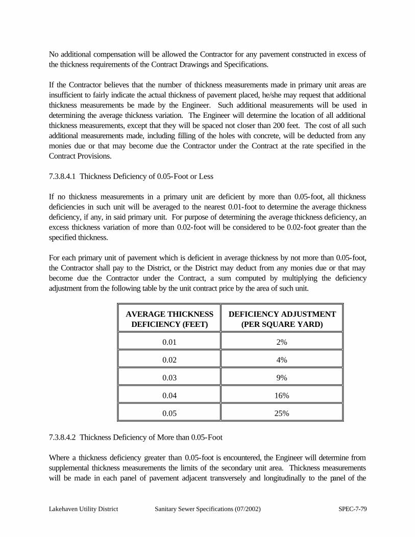
Lakehaven Utility District Sanitary Sewer Specifications (07/2002) SPEC-7-79
No additional compensation will be allowed the Contractor for any pavement constructed in excess of the thickness requirements of the Contract Drawings and Specifications. If the Contractor believes that the number of thickness measurements made in primary unit areas are insufficient to fairly indicate the actual thickness of pavement placed, he/she may request that additional thickness measurements be made by the Engineer. Such additional measurements will be used in determining the average thickness variation. The Engineer will determine the location of all additional thickness measurements, except that they will be spaced not closer than 200 feet. The cost of all such additional measurements made, including filling of the holes with concrete, will be deducted from any monies due or that may become due the Contractor under the Contract at the rate specified in the Contract Provisions. 7.3.8.4.1 Thickness Deficiency of 0.05-Foot or Less If no thickness measurements in a primary unit are deficient by more than 0.05-foot, all thickness deficiencies in such unit will be averaged to the nearest 0.01-foot to determine the average thickness deficiency, if any, in said primary unit. For purpose of determining the average thickness deficiency, an excess thickness variation of more than 0.02-foot will be considered to be 0.02-foot greater than the specified thickness. For each primary unit of pavement which is deficient in average thickness by not more than 0.05-foot, the Contractor shall pay to the District, or the District may deduct from any monies due or that may become due the Contractor under the Contract, a sum computed by multiplying the deficiency adjustment from the following table by the unit contract price by the area of such unit.
AVERAGE THICKNESS
DEFICIENCY (FEET)
DEFICIENCY ADJUSTMENT
(PER SQUARE YARD)
0.01
2%
0.02
4%
0.03
9%
0.04
16%
0.05
25%
7.3.8.4.2 Thickness Deficiency of More than 0.05-Foot Where a thickness deficiency greater than 0.05-foot is encountered, the Engineer will determine from supplemental thickness measurements the limits of the secondary unit area. Thickness measurements will be made in each panel of pavement adjacent transversely and longitudinally to the panel of the

SPEC-7-80 Sanitary Sewer Specifications (07/2002) Lakehaven Utility District
original measurement. This procedure will continue, regardless of unit boundaries, until such secondary unit area is bounded by panels with a thickness deficiency of 0.05-foot or less. Cores taken to isolate the secondary unit will not be used to compute average thickness of the primary unit. Panels are the areas bounded by longitudinal and transverse joints and pavement edges. If longitudinal or transverse joints are eliminated by the Contract Special Provisions, by the Contract Drawings, or for any other reasons, the limits of panels will be determined by the Engineer as if such joints had been constructed. The secondary unit area will be made up of entire panels only. The entire panel will be considered to be of the thickness shown by measurement. After the Engineer has determined the limits of the secondary unit area, he/she will determine further whether any panels within this area are usable and may be left in place. Following this determination, the Contractor shall remove and replace at his/her expense such panels as the Engineer may direct in accordance with the following: If the area to be removed is not bounded by longitudinal or transverse joints, the Contractor shall saw, at his/her expense, weakened plane joints at the locations designated by the Engineer. The subgrade shall be lowered as necessary to meet the full thickness requirements. Replaced pavement will be tested for thickness by means of additional measurements and will be subject to all of the requirements of the specifications. Usable panels may be removed and replaced as outlined above at the option of the Contractor, or he/she will be permitted to leave such panels in place, provided that no payment will be made for any such panels which are left in place and that a further penalty will be assessed in the amount of 25 percent of the Contractor's unit bid price for all such panels. The District may deduct such amount from any monies due or that may become due the Contractor under the Contract. The cost of all thickness measurements made to determine the secondary unit areas, including filling the holes with concrete, will be deducted at the rate designated in the Contract from any monies due or that may become due the Contractor under the Contract. All additional work required and any delay to the Contractor's operations as a result of these specifications shall not be cause for additional compensation nor for an extension of time. 7.3.9 Cement Concrete Sidewalk 7.3.9.1 The restoration of cement concrete sidewalk shall be accomplished by replacement of sidewalk where shown on the Contract Drawings or as directed by the Engineer. Restoration shall conform to the grade existing prior to construction and shall provide a smooth, continuous restoration of the sidewalk surface.
Lakehaven Utility District Sanitary Sewer Specifications (07/2002) SPEC-7-81
7.3.9.2 Materials, proportioning and mixing of concrete for sidewalks shall conform to the applicable requirements of Section 7.3.8 of these specifications.
SPEC-7-82 Sanitary Sewer Specifications (07/2002) Lakehaven Utility District
7.3.9.3 Contraction joint layout shall match that in adjacent sidewalk sections. 7.3.10 Cement Concrete Curb and Gutter 7.3.10.1 The restoration of cement concrete curb and gutter shall be accomplished by replacing curb and gutter where shown on the Contract Drawings or directed by the Engineer. Restoration shall conform to the line and grade existing prior to construction. Curb and gutter shall be in accordance with the standards of the governmental agency having jurisdiction. 7.3.10.2 Curb and gutter shall be uniform in appearance and structurally sound. Curbs found with unsightly bulges, ridges, low spots in the gutter or other defects shall be removed and replaced at the Contractor's expense, if the Engineer considers them to be irreparable. When checked with a ten (10) foot straightedge, grade shall not deviate more than 1/8-inch, and alignment shall not vary more than 1/4-inch. 7.3.10.3 Materials, proportioning and mixing of concrete for curb and gutter shall conform to the applicable requirements of Section 7.3.8 of these specifications. 7.3.11 Asphalt Concrete Overlay 7.3.11.1 In the locations shown on the Contract Drawings, or when directed by written instructions from the Engineer, pavement restoration shall be accomplished by installing an asphalt concrete overlay on the existing or restored pavement. 7.3.11.2 Before construction of an asphalt concrete pavement on an existing surface, all fatty asphalt patches, grease drippings, and other objectionable matter shall be entirely removed from the existing pavement. All excess asphalt joint filler shall be completely removed and all premolded joint filler shall be removed to at least 1/2-inch below the surface of the existing pavement. All types of existing pavement or bituminous surfaces shall be thoroughly cleaned by sweeping to remove dust and other foreign matter. A tack coat of asphalt applied at the rate of 0.02 to 0.08 gallon per square yard of retained asphalt shall be applied through the use of approved mechanical equipment to all surfaces on which any course of asphalt concrete is to be placed or abutted. The spreading equipment shall be capable of uniformly distributing asphalt materials over any area in controlled amounts and shall be equipped with hand-operated spray equipment for use only on inaccessible and irregularly shaped areas. The tack coat shall be a heated cutback asphalt, or emulsified asphalt, mixing grade, as directed by the Engineer. The emulsified asphalt may be diluted with water at a rate not to exceed one (1) part water to one (1) part of emulsified asphalt, as directed by the Engineer. 7.3.11.3 Asphalt concrete shall be as specified in these specifications, Section 7.3.6, and the construction of the asphalt concrete overlay shall conform to the applicable requirements of Section
Lakehaven Utility District Sanitary Sewer Specifications (07/2002) SPEC-7-83
7.3.6.3. Drainage structures in gutters will not be raised. All other utility appurtenances shall be adjusted to finish grade after the overlay is completed. Asphalt concrete overlay shall be "Ground Butt Jointed" into existing pavement as shown on the Contract Drawings or as directed by the Engineer. Overlay shall be placed in conjunction with pavement restoration where sewers are installed. 7.3.12 Gravel Surfacing Restoration of surfacing on unimproved public roadways shall be accomplished by installing gravel surfacing over the entire area of the traveled way, drainage ditch to drainage ditch. Unless otherwise directed by the Engineer, gravel surfacing shall have the same plan dimensions and grade as the surface existing prior to construction. Gravel surfacing shall be as specified for bituminous surface treatment pavement except that the Class A Bituminous Surface Treatment shall be omitted. 7.3.13 Pavement Markings The Contractor shall restore any and all pavement striping and traffic buttons damaged during construction under the Contract. The Contractor shall make said restoration in accordance with the current standards of the governmental agency having jurisdiction. The cost of restoration of pavement striping and traffic buttons shall be incidental to pavement restoration. 7.3.14 Maintenance Any soft, unstable or depressed areas that appear within the actual limits of trench excavation, or in any surface paved by the Contractor, within one (1) year after final acceptance by the governmental agency having jurisdiction, shall be repaired in the manner directed by the Engineer and at no cost to the Owner. 7.4 LANDSCAPING RESTORATION 7.4.1 Particular care shall be taken to minimize damage to landscaping within and adjacent to indicated rights-of-way, easements, and construction access areas. If landscaping located outside the indicated rights-of-way, easements and construction access areas is damaged by the construction work, it shall be replaced or restored by the Contractor to the satisfaction of the Engineer. 7.4.2 Lawns Not in Public Rights-of-Way 7.4.2.1 Lawn areas to be restored shall be resodded over a minimum depth of six (6) inches of topsoil. Topsoil shall be a friable loam soil free from weed seeds, roots, subsoil, stones and other debris and from materials toxic to plant growth. Lawn areas shall be restored using sod removed from the original lawn; refer to Sections 1 and 2 herein. 7.4.2.2 Resodding shall be completed within ten (10) days after removal of the sod. The finished grade, after shaping and compacting the topsoil, shall be thoroughly dampened prior to and immediately

SPEC-7-84 Sanitary Sewer Specifications (07/2002) Lakehaven Utility District
before replacing the sod. The sod shall be replaced to the required grade, taking care to butt each piece tightly against the adjacent one. Upon completion, the sod shall be dampened and rolled with a lawn roller. 7.4.2.3 Sod which is held for more than ten (10) days may be rejected by the Engineer. 7.4.3 Plants 7.4.3.1 The Contractor shall not remove any trees or shrubs without the authorization of the Engineer. The Contractor shall not remove, even temporarily, any trees or shrubs that exist on easements across private property or in parking strips, without first having notified the property owners or authorities maintaining same. DO NOT REMOVE any trees from the temporary construction access without obtaining written permission from the landowner. A copy of the written permission shall be transmitted to the Engineer. 7.4.3.2 Serious injuries to trees shall be avoided. The Contractor shall prevent damage to major roots, particularly those larger than two (2) inches in diameter. 7.4.3.3 Trees, shrubs and other plants that are to be replaced may be removed and replanted or may be replaced with new plants. Unless otherwise directed by the Engineer, new plants shall be the same size and species as the plant to be replaced. New plants shall be well-established stock, with normal branch systems and vigorous root systems, and shall be free from pests, diseases and disfiguring injury. 7.4.3.4 Plants that are to be replanted shall be carefully removed and the root ball shall be wrapped in burlap. Balled roots shall be kept continually moist. Plants shall be replanted in their original positions, within 48 hours, in topsoil extending 12 inches beyond the diameter of branches and to depth of 12 inches below the root ball. All plants shall be fertilized and watered. 7.4.3.5 Where trees with trunks less than four (4) inches in diameter and cultivated shrubs and other plants exist in an easement obtained for a pipeline, the Engineer may, at his discretion, order the Contractor to dig up and salvage said trees and shrubs and to replant them after installation of the pipeline. All trees in easements, which are to be replaced, shall be replaced as follows: 7.4.3.5.1 Trees under eight (8) feet in height shall be replaced with trees of the same size and kind. 7.4.3.5.2 Trees over eight (8) feet in height shall be replaced as follows:
Evergreens - same kind, seven (7) feet in height;
Deciduous - same kind, eight (8) feet in height; and
Fruit or Flowering - same kind, five (5) feet in height.
7.4.4 Public Rights-of-Way
Lakehaven Utility District Sanitary Sewer Specifications (07/2002) SPEC-7-85
7.4.4.1 Unless otherwise noted on the Contract Drawings, landscape restoration within public rights-of-way shall consist of the restoration of man-made improvements and the preparation of lawn and planting areas. 7.4.4.2 All man-made improvements damaged by the Contractor's operations shall be completely restored; such improvements include, but are not limited to, fences, walls, rockeries, driveways, sidewalks and other paving, bark mulch and sprinkler systems. Pavement restoration of roadways, cement concrete sidewalks and cement concrete curb and gutter in public rights-of-way shall be paid for under those respective unit price bid items listed in the Proposal. 7.4.4.3 Lawn and planting areas in public right-of-way disrupted by the Contractor's operations shall be covered with six (6) inches of topsoil. The topsoil shall be compacted and the area shall be finish-graded to conform to the surrounding elevations. Resodding and/or seeding are not provided. 7.4.4.4 Plants and shrubs that conflict with the construction will be removed by owners of adjacent property. The Contractor shall notify each property owner at least 48 hours in advance of any construction that requires the removal of plants. Plants remaining after expiration of the notification period may be removed by the Contractor and need not be replanted or replaced. Trees shall not be removed without the authorization of the Engineer. 7.4.5 Easements and Construction Access Areas 7.4.5.1 Landscaping and improvements within easements and temporary construction easement areas shall be restored in accordance with the terms, conditions and stipulations of the easement agreements, which are available for inspection at the Lakehaven Utility District offices, and are made a part of the Contract fully and for all purposes. Where the terms of the easement do not agree with the restoration requirements, as included herein, the terms of the easement shall supersede the Contract. Unless otherwise noted, all man-made improvements and all lawns, trees, shrubs and other plants that have been damaged by the Contractor's operations shall be restored to a condition equal or better than existed prior to construction. As a minimum, restoration shall comply with all requirements as specified herein. 7.4.5.2 Construction across and restoration and cleanup of easements and construction accesses shall be performed expeditiously and on a continuous basis until the work is completed. 7.4.5.3 Easement Release Where work is done on easements, the Contractor shall obtain a written statement (see following form) of satisfactory restoration from each property owner involved, and furnish a copy of said statement to the property owner and the District. The statement will be required before the work will be accepted by the District; provided, however, that where the Contractor contends the property owner is making unreasonable demands, he/she shall submit a list of such demands to the District in writing. If, in the
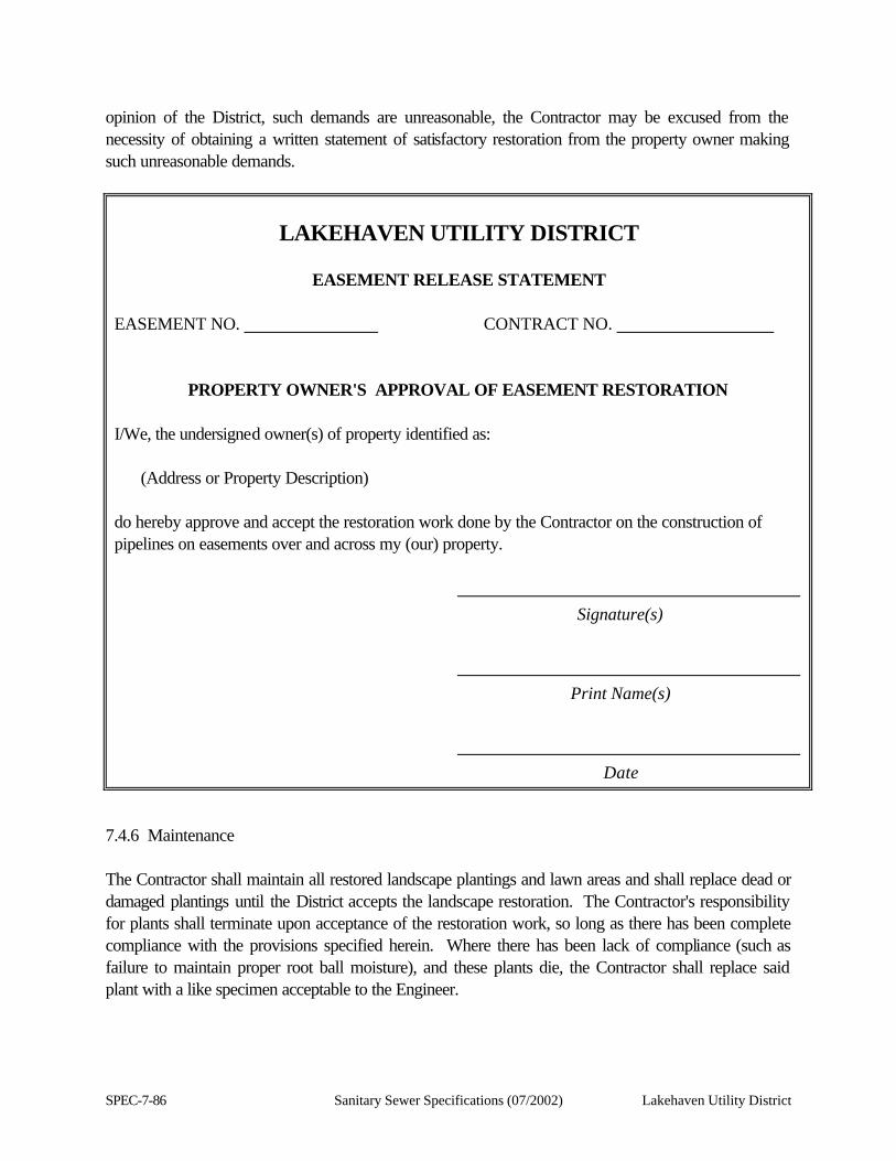
SPEC-7-86 Sanitary Sewer Specifications (07/2002) Lakehaven Utility District
opinion of the District, such demands are unreasonable, the Contractor may be excused from the necessity of obtaining a written statement of satisfactory restoration from the property owner making such unreasonable demands.
LAKEHAVEN UTILITY DISTRICT
EASEMENT RELEASE STATEMENT
EASEMENT NO. CONTRACT NO.
PROPERTY OWNER'S APPROVAL OF EASEMENT RESTORATION I/We, the undersigned owner(s) of property identified as: (Address or Property Description) do hereby approve and accept the restoration work done by the Contractor on the construction of pipelines on easements over and across my (our) property. Signature(s) Print Name(s) Date
7.4.6 Maintenance The Contractor shall maintain all restored landscape plantings and lawn areas and shall replace dead or damaged plantings until the District accepts the landscape restoration. The Contractor's responsibility for plants shall terminate upon acceptance of the restoration work, so long as there has been complete compliance with the provisions specified herein. Where there has been lack of compliance (such as failure to maintain proper root ball moisture), and these plants die, the Contractor shall replace said plant with a like specimen acceptable to the Engineer.
Lakehaven Utility District Sanitary Sewer Specifications (07/2002) SPEC-7-87
7.5 MONUMENT RESTORATION 7.5.1 The Contractor shall be required to preserve, where possible and practicable, all survey monuments and property corners whether or not shown on the Contract Drawings. Should any property corners or survey monuments need to be removed for construction or be accidentally disturbed as a result of the Contractor’s actions, then the Contractor shall be responsible to provide and enlist a Washington State licensed land surveyor to reference the monuments and property corners with "reference points" and otherwise preserve the location of said reference points prior to removing or destroying the monuments and/or property corners. Should any permits, forms, or any other documentation need to be acquired to temporarily remove and replace any reference point, then the Contractor shall also be required to procure and acquire same. There shall be no separate payment for referencing and replacing property corners and/or survey monuments, but such costs shall be considered incidental to the Project and no separate monies will be due. The monuments shall be replaced, in kind, or, as further detailed on the Contract Drawings. 7.5.2 The monument case shall be set in concrete as shown on the Plans. The bronze marker shall be set by the Contractor in a 2" diameter galvanized iron pipe. A land surveyor licensed and registered in the State of Washington and employed by the Contractor shall set the survey point within the monument case. 7.6 REMOVE AND REINSTALL EXISTING FENCES The Contractor shall be required to remove and reinstall existing wire, wood and cyclone fences where necessary to construct the sanitary sewer lines and appurtenances in existing easements and rights-of-ways. It shall be the Contractor's responsibility to insure that all existing fences are reinstalled as soon as practicable once sewer line construction is completed in the area where existing fences are disturbed. Any damage to existing fences as the result of the Contractor's operation shall be the Contractor's responsibility. All costs associated with removal and reinstallation of existing fences shall be considered incidental to the Contract. 7.7 WEIGHING 7.7.1 Weighing equipment for the weighing of cold mix asphalt and rock riprap shall consist of and conform to Section 1-09.2 of the Standard Specifications for Road, Bridge & Municipal Construction, of the State of Washington, 1996, except that commercially owned scales may be utilized, if they are satisfactory to and approved by the Engineer. In any event, public or privately owned scales shall be tested and sealed at the expense of the Contractor, specifically for this Project. 7.7.2 If public scales are used, the Contractor shall be responsible for the costs of weighing, as well as collecting all trip tickets. If the Contractor uses his own scales, then he shall stand all costs of weighing, including furnishing a certified and licensed weigh master or scaleman, as well as collecting all trip tickets and turning them over to the Engineer at the end of each working day.
SPEC-7-88 Sanitary Sewer Specifications (07/2002) Lakehaven Utility District
7.7.3 Weight or trip tickets shall be prepared to include the following information on each slip; date, time weight, time delivered, total weight, tare weight, net weight, name of driver, truck identifying number (using visible numbers or license plates), ticket number and type of material delivered, plus any other information needed. 7.7.4 Tare weights shall be taken of each truck on a daily basis as a check on weights; the inspector may, at any time, pull out of the line any truck and have it weighed at a commercial scale for both loaded and unloaded conditions. Cost of weight checking at commercial scales shall be paid by the Contractor. 7.8 ADJUST MANHOLES, CATCH BASINS & VALVE BOXES TO GRADE 7.8.1 Existing and new facilities shall be adjusted to grade as specified herein and further directed by the Engineer. All manholes, catch basins, and valve boxes lying within pavement surfaces or in areas to be regraded shall be "adjusted to grade." Surface monuments shall be installed where noted. Existing valve boxes, rings, grates and covers shall be reset in a careful and workmanlike manner to conform to the new grade. Special care shall be exercised in all operations. Any damage occurring to the manholes, valves, valve boxes, water mains, or catch basins, due to the Contractor's operations, shall be repaired at his/her own expense. Any masonry adjustment shall be made by using bricks, concrete blocks, or cement concrete and the interior of the manhole or catch basin adjustment shall be mortared smooth. Adjusting rings will be permitted at the Contractor' option. All covers and frames shall be thoroughly cleaned. The Contractor shall be responsible for referencing, and keeping a record of such references, of all manholes, catch basins, and valve boxes encountered, and shall submit a copy of these references to the Engineer. 7.8.2 All manholes, catch basins and valve boxes shall be adjusted to grade in the following manner: as soon as the street is paved past each manhole, catch basin and valve box, the asphalt concrete mat shall be scored around the location of the manhole or valve box. After rolling has been completed and the mat has cooled, it shall be cut along the scored lines. The manholes, catch basins and valve boxes shall then be raised to finished pavement grade and the annular spaces filled with cement concrete to within 1-1/2 inches of the finished grade. The remaining 1-/2 inches shall be filled with asphalt concrete Class B to give a smooth finished appearance. 7.8.3 After pavement is in place, all joints shall be sealed with hot asphalt cement (AR 4000W). 7.8.4 All valve boxes outside the pavement limits, to include hydrant valves, shall be brought to grade. 7.9 RESTORATION OF UNIMPROVED AREAS Contractor shall restore unimproved areas, such as pastures, brush and woods, using hydroseeding and additional restoration as may be required to prevent erosion of the construction disturbed areas.
Lakehaven Utility District Sanitary Sewer Specifications (07/2002) SPEC-7-89
7.9.1 General This work consists of restoring and repairing areas cleared, grubbed and otherwise disturbed by the Contractor while performing the Work, which areas are within unopened public rights-of-way and otherwise unimproved areas, and which are outside improved landscape and otherwise improved areas, as shown on the Plans or where directed by the Engineer or the governmental agency having jurisdiction. The restoration shall include, but not be limited to, final grading and revegetation by hydroseeding, all to a condition equal to or better than that which existed prior to performing the Work, to the satisfaction of the District, the affected private property owner, and to the governmental agency having jurisdiction. Where required by the Engineer, the Contractor shall obtain written releases from affected private property owners and the governmental agency having jurisdiction, evidencing that the area disturbed by the Contractor has been restored to the satisfaction of said parties. Hydroseeding shall be performed not more than three (3) weeks after trench backfilling and compaction. Hydroseeding shall be performed on a weekly basis if trench backfilling and compacting cannot be completed within a three (3) week period. When the Work is performed beyond the most favorable planting season or when weather conditions are such that satisfactory results are not likely to be obtained for any stage of the hydroseeding operations, the Contractor will stop the work and it shall be resumed only when the desired results are likely to be obtained or when approved alternates or corrective measures and procedures are adopted and approved by the District. The exact time for hydroseeding will be determined by actual weather conditions. The normal satisfactory periods shall be considered as being between March 1 and May 1, and between September 15 and October 20. All additional costs associated with delays in hydroseeding shall be borne by the Contractor. Final grading shall include complete grading, leveling, surface restoration and shaping of the entire area to make it neat and smooth in appearance and will require hand labor over and above that which can be performed by equipment. No ruts or ridges that are apparent to the eye shall be acceptable prior to acceptance of the project. All surfaces shall be well graded to provide uniform slopes and to provide shaped surfaces capable of carrying off the surface water without ponding. To obtain the neat appearance desired, the Contractor shall use hand labor in areas not graveled and remove exposed rocks. Where shown on the Plans, or otherwise directed by the Engineer or the governmental agency having jurisdiction, the Contractor shall place jute matting, erosion control blanket, clear plastic covering or a combination of these materials meeting the requirements of "Matting" (herein below) over disturbed surfaces of slope areas to control soil erosion (Also see Section 2.5). These material shall be placed in
SPEC-7-90 Sanitary Sewer Specifications (07/2002) Lakehaven Utility District
conformance with Section 8-01.3(8) "Placing Jute Matting, Erosion Control Blanket, or Clear Plastic Covering" of APWA/WSDOT. All costs to furnish and place jute matting, erosion control blanket, clear plastic covering or a combination of these materials are incidental to the Contract and are the responsibility of the Contractor. The Contractor shall include all related costs in the unit or lump sum bid prices of the Contract. 7.9.1.1 Matting 7.9.1.1.1 Jute Matting Jute matting shall be of a uniform open plain weave of unbleached, single jute yarn treated with a fire retardant chemical. The yarn shall be of a loosely twisted construction and shall not vary in thickness by more than one-half of its normal diameter. Jute matting shall be furnished in rolled strips approximately fifty (50) yards in length. Matting width shall be forty-eight inches (48”) with an average weight of 0.92 pounds per square yard. A tolerance of plus or minus one inch (±1”) in width and five percent (5%) in weight will be allowed. 7.9.1.1.2 Erosion Control Blanket Erosion control blanket shall be a machine-produced mat of wood excelsior covered on one side with a plastic netting or of twisted paper composition. The erosion control blanket shall have a minimum dry weight of wood fibers of 0.8 pounds per square yard, plus or minus five percent (±5%). It shall be of uniform thickness, with the fiber evenly distributed over the entire area of the mat. The plastic netting shall have a 3-inch by 3-inch maximum mesh size. The width of matting and net shall be thirty-six inches (36”) and the rolls shall be approximately one hundred fifty feet (150’) long. 7.9.1.1.3 Clear Plastic Covering Clear plastic covering shall meet the requirements of the NBS Voluntary Product Standard, PS 17-69, for polyethylene sheeting, having a minimum thickness of six (6) mils. 7.9.2 Hydroseeding Hydroseeding shall utilize water as the carrying agent, and maintain continuous agitation through paddle blades. It shall have an operating capacity sufficient to agitate, suspend and mix into a homogenous slurry the specified amount of seed and water or other material. Distribution and discharge lines shall be large enough to prevent stoppage and shall be equipped with a set of hydraulic discharge spray nozzles that will provide a uniform distribution of the slurry.
Lakehaven Utility District Sanitary Sewer Specifications (07/2002) SPEC-7-91
Hydroseeding shall not be performed during windy weather or when the ground is frozen, excessively wet or otherwise untillable. Care shall be exercised to prevent the hydroseed slurry from entering any surface waters. The hydroseed slurry shall consist of grass seed meeting requirements listed as “Seed” below, and shall be applied at the rate of one hundred thirty (130) pounds per acre. Fertilizer meeting the requirements listed as “Fertilizer” shall be applied at the rate of three hundred (300) pounds per acre. Wood cellulose fiber meeting the requirements listed as “Wood Cellulose Fiber” below shall be applied at the rate of two hundred fifty (250) pounds per acre. 7.9.2.1 Seed Grasses, legumes, or cover crop seed of the type specified shall conform to the standards for “Certified” grade seed, or better, as outlined by the State of Washington Department of Agriculture “Rules for Seed Certification,” latest edition. Seed shall be furnished in standard containers on which shall be shown the following information: (1) Common name of seed.
(2) Lot number.
(3) Net weight.
(4) Percentage of purity.
(5) Percentage of germination. (In case of legumes, percentage of germination to include hard seed.)
(6) Percentage of weed seed content and inert material clearly marked for each kind of seed in accordance with applicable State and Federal laws.
Upon request, the Contractor shall furnish to the Engineer duplicate copies of statements signed by the vendor certifying that each lot of seed has been tested by a recognized seed testing laboratory within six (6) months before the date of delivery on the project. Seed that has become wet, moldy, or otherwise damaged in transit or storage, will not be accepted.
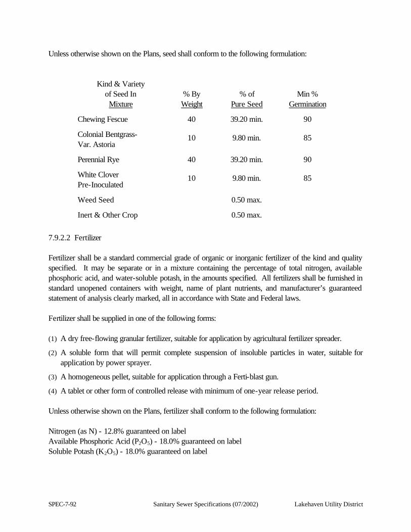
SPEC-7-92 Sanitary Sewer Specifications (07/2002) Lakehaven Utility District
Unless otherwise shown on the Plans, seed shall conform to the following formulation:
Kind & Variety of Seed In Mixture
% By Weight
% of
Pure Seed
Min %
Germination
Chewing Fescue 40 39.20 min. 90
Colonial Bentgrass- Var. Astoria
10 9.80 min. 85
Perennial Rye 40 39.20 min. 90
White Clover Pre-Inoculated
10 9.80 min. 85
Weed Seed 0.50 max.
Inert & Other Crop 0.50 max.
7.9.2.2 Fertilizer Fertilizer shall be a standard commercial grade of organic or inorganic fertilizer of the kind and quality specified. It may be separate or in a mixture containing the percentage of total nitrogen, available phosphoric acid, and water-soluble potash, in the amounts specified. All fertilizers shall be furnished in standard unopened containers with weight, name of plant nutrients, and manufacturer’s guaranteed statement of analysis clearly marked, all in accordance with State and Federal laws. Fertilizer shall be supplied in one of the following forms: (1) A dry free-flowing granular fertilizer, suitable for application by agricultural fertilizer spreader.
(2) A soluble form that will permit complete suspension of insoluble particles in water, suitable for application by power sprayer.
(3) A homogeneous pellet, suitable for application through a Ferti-blast gun.
(4) A tablet or other form of controlled release with minimum of one-year release period. Unless otherwise shown on the Plans, fertilizer shall conform to the following formulation: Nitrogen (as N) - 12.8% guaranteed on label Available Phosphoric Acid (P2O5) - 18.0% guaranteed on label Soluble Potash (K2O5) - 18.0% guaranteed on label
Lakehaven Utility District Sanitary Sewer Specifications (07/2002) SPEC-7-93
Not less than twenty-nine percent (29%) of the total nitrogen shall be derived from ureaform or ureaformaldephyde. The final mix shall not contain less than 2.6% of water-insoluble nitrogen. 7.9.2.3 Wood Cellulose Fiber Fiber shall be produced from natural or recycled (pulp) fiber, such as wood chips or similar wood materials, or from newsprint, corrugated cardboard, or a combination of these processed materials. The fibers shall not contain any rock, metal or plastic. It shall be treated with a non-toxic green dye to facilitate inspection of the placement of the material. It shall be manufactured in such a manner that, after addition and agitation in slurry tanks with water, the fibers in the material will become uniformly suspended to form a homogenous slurry. When hydraulically sprayed on the ground, the material shall allow the absorption and percolation of moisture. The product shall contain less than two hundred fifty parts per million (250 ppm) baron, and shall be otherwise non-toxic to plant or animal life. The organic matter content shall be at least ninety-three percent (93%) on an oven-dry basis, as determined by ASTM D586. The moisture content shall be no more than fifteen percent (15%) as determined by oven-dried weight. Each package of the cellulose fiber shall be marked by the manufacturer to show the dried weight. The Contractor shall protect all hydroseed areas from erosion and damage by any other means or cause. Areas damaged, or where a uniform growth of grass had not been achieved, shall be repaired by the Contractor at his/her own expense. All areas hydroseeded shall be maintained by the Contractor according to the directions of the vendor/subcontractor applying the hydroseed mixture.
Lakehaven Utility District Sanitary Sewer Specifications (07/2002) SPEC-8-1
SECTION 8
CLEANUP 8.1 GENERAL 8.1.1 During the progress of the work, the Contractor shall keep the premises occupied by him in a neat and clean condition, disposing of refuse in a satisfactory manner. 8.1.2 At no time shall the Contractor permit any accumulation of rubbish, excavated material, equipment or any other material that would interfere with the convenience or operations of others or result in unsafe working conditions. The Contractor shall program his/her work in a manner that will keep streets and landscaped areas free of dust, mud and debris. For additional requirements for the disposal of clearing debris and excavated material, see Specification Sections 1 and 3. 8.1.3 Dust shall be controlled at all times during the progress of the work by watering and sweeping. The Contractor shall take the necessary actions to control dust in a positive manner; and should the Contractor fail to take such positive action, the Owner shall order corrective work performed by others and deduct the costs of said corrective action from monies due the Contractor under Contract. 8.1.4 Paved streets and other paved areas shall be swept clean as soon as repaving is completed and at such other periods deemed necessary by the Owner in order to prevent nuisance to the adjacent homeowners or users of the street or area. Power brooms that do not catch and contain the dust and dirt being swept are prohibited. 8.2 CLEANUP 8.2.1 On completion of the work, the Contractor shall promptly remove from the vicinity all his/her equipment, all temporary structures and all surplus material, including construction debris, lumber, dirt, etc. 8.2.2 The Contractor shall return all lands disturbed by the construction to a condition at least equal to that existing prior to construction of the project, including removal and backfilling of temporary construction access roads and vehicular and equipment storage areas, etc. All damage to earthwork by erosion shall be filled, regraded and seeded (if required) as required to conform to the Contract Drawings and Specifications (Also see Section 2.5). 8.2.3 All pipelines shall be flushed and debris shall be removed from all manholes prior to acceptance of the project by the owner. All material shall be removed from all surfaces not intended to receive them.
SPEC-8-2 Sanitary Sewer Specifications (07/2002) Lakehaven Utility District
8.3 PROTECTION OF WORK The Contractor shall be responsible for the care of all work until its completion and final acceptance; and shall, at his/her own expense, replace damaged or lost material, repair damaged parts or work, or the same may be done at the expense of the Owner and charged to the Contractor. The Contractor and his/her sureties shall be liable for such work performed by the Owner under this section.
Lakehaven Utility District Sanitary Sewer Specifications (07/2002) SPEC-9-1
SECTION 9
MEASUREMENT AND PAYMENT 9.1 PRELIMINARY GENERAL INFORMATION 9.1.1 Payment for the work under contract shall be at the contract prices, which prices shall be full compensation for furnishing all labor, materials, tools and equipment and doing all work to construct a particular item of work as specified herein. 9.1.2 Unless otherwise specified hereinafter, or in another bid item, compensation for all clearing, pavement removal, excavation, excavation bracing, dewatering, bedding material, unsuitable material and its disposal, backfill and its compaction, landscaping restoration and testing required for the work included in the project shall be included in the Contractor's unit prices for gravity and pressure sewer pipelines and side sewers. 9.1.3 In the final determination of quantities of work done in accordance with the Contract Specifications and Drawings, at the prices set forth in the Contractor's accepted bid, the following methods of measurement shall be used. 9.1.4 For lump sum bid items: 9.1.4.1 Contractor, within ten days after the Effective Date of Agreement, shall submit to the Engineer for review, four copies of a preliminary Schedule of Values for all of the Work, which will include quantities and prices of items aggregating the Contract Price and will subdivide the Work into component parts in sufficient detail to serve as the basis for progress payments during construction. Such prices will include an appropriate amount of overhead and profit applicable to each item of Work, which will be confirmed in writing by Contractor at the time of submission. One review copy of the Schedule of Values, with comments (if any), shall be returned to contractor for revisions. 9.1.4.2 At least 10 days prior to the cut-off date for the first progress payment, Contractor shall submit to Engineer for review, four copies of a final Schedule of Values of the Work. The finalized Schedule of Values will be acceptable to the Engineer as to form and substance. When accepted, one copy of the final Schedule of Values shall be returned to Contractor and shall be used in processing partial payment for Lump Sum Bid items.
SPEC-9-2 Sanitary Sewer Specifications (07/2002) Lakehaven Utility District
9.2 CONSTRUCTION 9.2.1 Description, Materials and Construction Requirements are as described in other sections herein, on the plans, and in the WSDOT/APWA specifications. In case of conflict, the following priority system, in descending order of precedence, shall be recognized:
1. Change Orders (if any) 2. Agreement Form 3. Addenda (if any) 4. Proposal 5. Special Provisions (if any) 6. Engineering Specifications 7. Supplemental General Conditions (if any) 8. Plans 9. General Conditions 10. Amendments to WSDOT/APWA 11. Standard Specifications for Road, Bridge and Municipal Construction (WSDOT/APWA)
9.3 BID ITEMS/GENERAL 9.3.1 Mobilization, Cleanup And Demobilization 9.3.1.1 The lump sum bid for Mobilization, Cleanup and Demobilization shall include all costs associated with moving in, cleanup, moving out and any other "fixed" costs related to the project not materially affected by change in quantities of work performed. 9.3.1.2 Items included, but not limited to, the following: 9.3.1.2.1 All debris or rubbish caused by the Contractor's operations shall be removed and the entire work areas occupied during such operations shall be cleaned and left in a neat, presentable and workmanlike condition and appearance, to the satisfaction of the District, any affected private property owners, and any City, County, or State governmental agency having jurisdiction. 9.3.1.2.2 During construction, and then upon completion of the work, the Contractor shall thoroughly search the surrounding area and remove and dispose of any construction material thrown or discharged amongst the trees or elsewhere; such as paint cans, cartons, broken pipe, bottles, rocks, logs, excess excavated material and other deleterious matter. The general surrounding area shall be left neat in appearance. The Contractor shall also remove and dispose of debris not necessarily deposited by the Contractor while performing the work. 9.3.1.2.3 Paved surfaces, existing and new, shall be washed clean upon completion of work within the area and may require daily washing and/or sweeping, if mud or dust persist. Drainage ditches and other storm drainage facilities shall be left free of any material or damage resulting from the Contractor's operations. 9.3.1.2.4 Prior to project acceptance, all paved surfaces and surface and subsurface facilities shall be checked and cleaned as required.
Lakehaven Utility District Sanitary Sewer Specifications (07/2002) SPEC-9-3
9.3.1.2.5 Cleanup work shall progress as closely behind the backfilling operation and other construction work as possible to allow return of the construction area to normal use.

SPEC-9-4 Sanitary Sewer Specifications (07/2002) Lakehaven Utility District
9.3.1.3 Progress payment for the lump sum item "Mobilization, Cleanup and Demobilization" shall be made as follows: 9.3.1.3.1 When ten percent (10%) of the total original Contract amount is earned, less Mobilization, Cleanup and Demobilization, excluding amounts paid for Materials on Hand, seventy-five percent (75%) of the lump sum amount bid for Mobilization, Cleanup and Demobilization, or ten percent (10%) of the total original Contract amount, whichever is the least, shall be paid. 9.3.1.3.2 Upon completion of all work on this Project, payment for the remaining amount bid for Mobilization, Cleanup and Demobilization in excess of ten percent (10%) of the total original Contract amount, shall be paid. 9.3.1.4 Nothing herein shall be construed to limit or preclude progress payments otherwise provided by this Contract. 9.3.2 Traffic Control Measurement and payment for Traffic Control shall be on a lump sum basis, which shall include, but not be limited to, all Work, labor, equipment and materials involved in traffic control as described elsewhere in these specifications. 9.3.3 Clearing And Grubbing Measurement and payment for Clearing and Grubbing shall be per acre to the nearest tenth of an acre, as measured to the nearest square foot. This bid item shall be for the area cleared and grubbed per Section 1 - Clearing of these Sewer Specifications; to include, but not be limited to, all Work, labor, equipment and materials involved in clearing, grubbing, haul, and disposal of material within the clearing limits actually cleared and grubbed. Cutting and removal of significant trees within the clearing limits will be accomplished by others and shall not be included as part of this bid item, except that removal of stumps remaining from the tree removal process shall be included under this bid item. Also included in this bid item is delineating the clearing limits, as indicated on the plans, prior to any clearing or grading, with continuous orange construction fencing, a minimum of 3 to 6 feet in height. Contractor shall furnish, install, maintain during construction activities, and remove construction fencing after project completion. 9.3.4 Temporary Erosion And Sedimentation Control (TESC) Facilities The force account (FA) price contained in the bid proposal for TESC Facilities shall be used at the direction of the Engineer for resolution of field identified conditions or problems arising from needed or required temporary erosion and sedimentation control. Payment shall be for items which shall include but not be limited to all Work, labor, equipment and materials involved in the construction, maintenance, removal, and disposal of the temporary erosion and sedimentation control facilities as described elsewhere in these specifications, as shown on the plans and details, and as directed by Engineer. If specific facilities are included in the proposal as a separate bid item, they shall be paid for as such and
Lakehaven Utility District Sanitary Sewer Specifications (07/2002) SPEC-9-5
not included in this bid item. Payment for authorized work in connection with TESC Facilities shall be made by force account method against this bid item, per Section 22 of the General Conditions and Section 1-09.6 of the Standard Specifications (WSDOT/APWA). No payment shall be made for force account TESC Facilities work completed without prior authorization by the Engineer. 9.3.5 Silt Fence Measurement and payment for Silt Fence shall be per lineal foot as measured along the fence The price per lineal foot shall include, but not be limited to, all Work, labor, equipment and materials involved in the construction, maintenance, removal, and disposal of the silt fence as described elsewhere in these specifications and as shown on the plans and details. Location of the silt fence shall be as shown on the plans or as directed by the Engineer or the governing agency. 9.3.6 Straw Bale Dikes Measurement and payment for Straw Bale Dikes shall be per each as shown on the plans. The price per each shall include, but not be limited to, all Work, labor, equipment and materials involved in the construction, maintenance, removal, and disposal of straw bale dikes as described elsewhere in these specifications and as shown on the plans and details. Location of the straw bale dikes shall be as shown on the plans or as directed by the Engineer or the governing agency. 9.3.7 Rip Rap For Erosion Control 9.3.7.1 The payment for Rip Rap for Erosion Control (including construction entrances), where its installation is directed by written instructions from the Engineer, shall include removal and disposal of unsuitable material and furnishing and placing Rip Rap for Erosion Control, all as specified herein. 9.3.7.2 The quantity for payment shall be the tons of Rip Rap, Quarry Spalls, and Ballast Material installed, as determined to the nearest tenth of a ton. Certified weight bills shall be furnished with each load of materials delivered each day and payment quantities shall be determined from these bills. 9.4 BID ITEMS/TRENCH EXCAVATION, BEDDING, BACKFILL AND RESTORATION 9.4.1 Trench Excavation Safety Systems All costs of providing, installing, maintaining, and removing those items necessary to comply with the requirements as listed herein, and to meet WISHA requirements, shall be merged in the lump sum price bid for "Trench Excavation Safety Systems." The lump sum price bid shall be paid in increments proportional to the total length of pipe installed. Costs for WISHA compliance shall not be incidental to any other bid items.
SPEC-9-6 Sanitary Sewer Specifications (07/2002) Lakehaven Utility District
9.4.2 Foundation Material 9.4.2.1 The payment for Foundation Material, where its installation is directed by written instructions from the Engineer, shall include removal and disposal of unsuitable material and furnishing and placing foundation material, all as specified herein. 9.4.2.2 The quantity for payment shall be the tons of Foundation Material installed, as determined to the nearest tenth of a ton. Certified weight bills shall be furnished with each load of materials delivered each day and payment quantities shall be determined from these bills. 9.4.2.3 No payment will be made for Foundation Material required because the Contractor excavates below the grade required by the Contract Drawings and specifications without the written authorization of the Engineer. See Specification Section 3.3. 9.4.3 Select Backfill 9.4.3.1 The payment for Select Backfill, where its installation is directed by written instructions from the Engineer, shall include excavation, haul, removal and disposal of unsuitable material and furnishing, placing and compacting Select Backfill material, all as specified herein. 9.4.3.2 The quantity for payment shall be the volume in cubic yards of Select Backfill as determined by the product of the length of pipe installed, multiplied by the depth, from the top of the initial backfill, one (1) foot above the crown of the pipe, to the subgrade for roadway or pavement, multiplied by the maximum payment trench width. The maximum payment trench width shall be defined for use in this section as follows:
40 inches for pipe sizes 15 inch inside diameter and smaller
1.5 X inside diameter + 18 inches for pipe sizes larger than 15 inch inside diameter
No extra payment for this bid item will be allowed to the Contractor where sheeting or trench boxes are used. The quantity of Select Backfill shall be calculated to the nearest cubic yard. 9.4.3.3 No payment will be made for Select Backfill required because the Contractor excavates outside the lines and grades required by the Contract Drawings and Specifications without the written authorization of the Engineer. 9.4.4 Crushed Surfacing Top Course (For Surface Repair & For Trench Backfill) 9.4.4.1 Payment for Crushed Surfacing Top Course For Surface Repair shall include furnishing placing and compacting crushed surfacing for paving preparation, roadway shoulders, driveways, “Gravel Access Areas” and “Gravel Access Road.” Payment for crushed surfacing for roadway shoulder repair shall be a maximum of three (3) feet past the edge of pavement. Any area requiring more than three (3)
Lakehaven Utility District Sanitary Sewer Specifications (07/2002) SPEC-9-7
feet of crushed surfacing shall be considered incidental and included in the various bid items, unless those areas are identified on the Contract Drawings. Depths shall be determined by the standards of the governmental agency having jurisdiction, as described in these specifications or as directed by the Engineer. 9.4.4.2 Payment for Crushed Surfacing Top Course For Trench Backfill shall include furnishing, placing and compacting crushed surfacing, where crushed surfacing is required for backfill. 9.4.4.2.1 The payment for Crushed Surfacing Top Course For Trench Backfill, where its installation is directed by written instructions from the Engineer or governing road agency, shall include excavation, haul, removal and disposal of unsuitable material and furnishing and placing Crushed Surfacing Top Course For Backfill Material, all as specified herein. 9.4.4.2.2 The maximum volume allowed for payment shall be the length along the pipe installed, by the depth, from the top of the initial backfill or one (1) foot above the crown of the pipe, to the subgrade for roadway or pavement, as directed by the Engineer or governing road agency, by the maximum payment trench width. The maximum payment trench width shall be defined for use in this section as follows:
40 inches for pipe sizes 15 inch inside diameter and smaller
1.5 X inside diameter + 18 inches for pipe sizes larger than 15 inch inside diameter
No extra payment for this bid item will be allowed to the Contractor where sheeting or trench boxes are used. The quantity of Crushed Surfacing Top Course For Trench Backfill shall be calculated to the nearest tenth of a ton. 9.4.4.2.3 No payment will be made for Crushed Surfacing Top Course For Trench Backfill required because the Contractor excavates outside the lines and grades required by the Contract Drawings and Specifications without the written authorization of the Engineer. 9.4.4.3 The quantity for payment of crushed surfacing shall be determined by the ton. Certified weight bills shall be furnished with each load of materials delivered each day, and payment quantities shall be determined from these bills. 9.4.5 Cold Mix, Temporary Repair 9.4.5.1 Payment for Cold Mix, Temporary Repair, shall include all costs for stock piling, placing, shaping and compacting the subgrade to a smooth, uniform surface prior to placing the material, and for removal and disposal of the cold mix prior to permanent pavement repair. 9.4.5.2 Measurement for payment shall be per ton for quantities actually used as directed by the Engineer.
SPEC-9-8 Sanitary Sewer Specifications (07/2002) Lakehaven Utility District
9.4.6 Asphalt Concrete Pavement Restoration 9.4.6.1 The Owner at its sole discretion, can vary the quantity for Asphalt Concrete Pavement Restoration from 0 to 125 percent of the sum of all quantities shown for this item. The Owner and Contractor expressly agree that the unit price bid for these items shall not be subject to negotiation for installed quantities within these limits. No adjustment will be made for lost overhead and profit on zero (0) quantity under run. 9.4.6.2 Payment for pavement restoration shall include subgrade preparation, furnishing and placing gavel base, crushed surfacing top course, asphalt concrete, bituminous surface treatment, and all other items of work required for the restoration of asphalt pavement as specified herein or shown on the Contract Drawings, unless specified herein for another bid item. These items shall also include the maintenance of unrestored roadways and furnishing, placing additional crushed surfacing top course material, maintaining the temporary surfacing, dust control, removing and disposing of the additional crushed surfacing top course material prior to permanent pavement restoration, matching existing driveways, and all other items of work required for surfacing as specified herein. During construction that requires the cutting of asphalt driveways, no payment outside of the pay limits for the roadway section will be allowed. All costs for cutback of driveways caused by the Contractors operation shall be born by the Contractor and shall be considered incidental to the project.,, 9.4.6.3 The quantity for payment shall be the gross surface area in square yards of the completed pavement restoration calculated to the nearest square yard from field measurements made to the nearest foot. The surface area calculations shall be based on the smaller of either the width of the actual pavement restoration or the pay limits as determined by the following equation:
W = Pay limit width of pavement in feet W = 1.5 (h+D+1) feet where: h = Vertical distance from top of pavement to invert of pipe in feet and D = Pipe ID in feet
The area of pavement in square yards equals the width as defined above, times the difference in stationing of sewer divided by 9. 9.4.7 Cement Concrete Pavement Repair 9.4.7.1 Payment for Cement Concrete Pavement Repair shall include saw cutting, removal and disposal of existing concrete pavement, all materials, proportioning, mixing, placing, compaction, finishing and curing to provide a smooth continuous pavement surface that matches adjacent pavement sections. Payment for Cement Concrete Pavement Repair shall only be made where shown on the Contract Drawings, or where instructed by the Engineer.
Lakehaven Utility District Sanitary Sewer Specifications (07/2002) SPEC-9-9
9.4.7.2 The quantity for payment shall be the gross surface area of surface replaced calculated to the nearest square yard from field measurements made to the nearest foot. Depth of cement concrete shall be no less than equal to that present prior to construction.
SPEC-9-10 Sanitary Sewer Specifications (07/2002) Lakehaven Utility District
9.4.8 Concrete Curb Removal And Replacement 9.4.8.1 Payment for Concrete Curb Removal and Replacement shall include saw cutting and removal of existing curb, disposal of waste materials, grading, erecting forms, furnishing and placing of concrete, stripping forms, finishing concrete and all other items of work required to construct concrete curb and gutter as specified herein or shown on the Contract Drawings. 9.4.8.2 Quantity for payment shall be the length of concrete curb measured along the face of curb from field measurements made to the nearest foot. 9.4.9 Cement Concrete Sidewalks 9.4.9.1 Payment for cement concrete sidewalks shall include all materials, proportioning, mixing, placing, compaction, finishing and curing to provide a smooth continuous sidewalk surface that matches adjacent sidewalk sections. Payment for sidewalk construction shall only be made for that shown on the Contract Drawings, or where instructed by the Engineer. 9.4.9.2 The quantity for payment shall be the gross surface area of sidewalk calculated to the nearest square foot from field measurements made to the nearest 1/2 foot. 9.4.10 Cement Concrete Driveway Repair 9.4.10.1 Payment for cement concrete driveways shall include all materials, proportioning, mixing, placing, compaction, finishing and curing to provide a smooth continuous driveway surface that matches adjacent driveway sections. Payment for driveway construction shall only be made for that shown on the Contract Drawings, or where instructed by the Engineer. 9.4.10.2 The quantity for payment shall be the gross surface area of driveway calculated to the nearest square foot from field measurements made to the nearest 1/2 foot. Depth of cement concrete shall be no less than equal to that present prior to construction. 9.4.11 Surface Restoration 9.4.11.1 Measurement of “Surface Restoration” shall be on a lump sum basis which shall include, but not be limited to, restoration of all surfaces damaged or removed by the Contractor’s operations, except those items included in other bid items. Some items included are: (1) Ditch restoration.
(2) Removal and reinstallation or replacement of existing culverts that have been disturbed by construction, including quarry spalls where required to line any ditch and or stabilize any bank.
(3) Restoring all unpaved surfaces, lawns, and landscaping disturbed by the Contractor’s operations.
(4) Restoring unimproved areas, such as pastures, brush and woods.
Lakehaven Utility District Sanitary Sewer Specifications (07/2002) SPEC-9-11
9.4.11.2 Payment shall be on a lump sum basis, with partial payments based on percentage of the total restoration value completed as detailed in a “schedule of values” supplied by the Contractor and reviewed by the Engineer prior to any construction. 9.4.12 Wetland Buffer Restoration Measurement and payment for Wetland Buffer Restoration shall be on a lump sum basis; which shall include, but not be limited to, all work, labor, equipment and materials involved in the construction and maintenance of items as shown on the Wetland Buffer Restoration-Planting Plan, on the Wetland Buffer Restoration Specification-Plan and as shown elsewhere herein. Removal and disposal of any materials as shown on said plans shall also be included. If specific items are a separate bid item, they shall be paid for as such and not included in this bid item. 9.4.13 Hydroseeding 9.4.13.1 The measurement for payment shall be the gross surface area of surface hydroseeded, calculated to the nearest tenth of an acre from field measurements made to the nearest yard. Coverage shall be as described in Section 7.9 herein. 9.4.13.2 Payment for “Hydroseeding” shall be on a per acre basis; which shall include, but not be limited to, all Work, labor, material and equipment required to hydroseed areas such as pastures, brush, woods, other areas as may be required to prevent erosion of the construction disturbed areas and as required by governmental agencies having jurisdiction. 9.5 BID ITEMS/GRAVITY AND PRESSURE SEWER PIPE AND CASINGS 9.5.1 Connect To Existing System (Gravity & Force Main) Measurement and payment shall be per each for each permanent connection to an existing manhole or existing force main. The bid per each connection to an existing sewer manhole or sewer force main shall constitute full compensation for all Work, labor, materials, and equipment necessary to connect the new gravity sewer line into the existing sewer manhole or the new force main to the existing force main. Bid item(s) to include coring and rechanneling the manhole, plugging the existing pipe, and cutting, capping, removal of a portion of and abandonment of the existing force main all as described herein and as shown and described on the plans. Excavation, backfill and fittings necessary for the connection shall be included as part of the lineal footage for the pipe. 9.5.2 Gravity And Pressure Sewer Pipelines 9.5.2.1 Gravity Sewer Pipelines: The payment for work constructed under these items shall include clearing, pavement removal and disposal, temporary erosion and sedimentation control, excavating, trench bracing, augering, tunneling, dewatering, furnishing and installing sewer pipe, concrete anchors, casing pipe, bedding and its compaction, clay dams, backfill and its compaction, cleaning and testing
SPEC-9-12 Sanitary Sewer Specifications (07/2002) Lakehaven Utility District
installed pipelines, landscaping restoration, groundwater surge relief lines and all other items of work specified herein or shown on the Contract Drawings, unless specifically listed as a payment item herein. See Specification Section 4 for alternative pipe types. Where a specific pipe type is listed in an item, that item shall apply to the installation of that pipe type only where specified on the Contract Drawings, or where directed in writing by the Engineer. The unit prices for tunneled crossings includes the furnishing and installation of both the liner or casing, pipe support and all other items of work specified herein. The cost for gravity sewer pipeline for tunnel crossings shall be included under the total length of gravity sewer pipeline. 9.5.2.2 Pressure Sewer Pipelines: The payment for work constructed under these items includes clearing, pavement removal and disposal, temporary erosion and sedimentation control, excavating, trench bracing, augering, tunneling, dewatering, furnishing and installing force main pipe and appurtenances required, concrete anchors, casing pipe, bedding and its compaction, clay dams, backfill and its compaction, installing marker tape, cleaning and testing installed force main or pressure sewer, landscape restoration, support and restoration of utilities, and other items of work specified in these Specifications or shown on the Contract Drawings unless specifically listed as a payment item herein. 9.5.2.3 The quantities for payment shall be the length in lineal feet of sewer pipeline, measured in place after completion and acceptance of the work. The measurement shall be the slope-distance of the finish ground surface along the pipeline location, measured to the nearest foot between the centerline of manholes or sewer terminals, without deduction for manholes, cleanouts or service fittings. Price for the completed sewer shall include all fittings except service fittings. 9.5.2.4 No partial payment will be made for installed gravity sewer pipelines until the trench backfill has been placed and compacted and has been approved by the Engineer. 9.5.2.5 Testing and Television Inspection 9.5.2.5.1 Payment for all equipment and labor needed to perform the initial television inspection of gravity sewer pipe shall be paid by the Owner. 9.5.2.5.2 The cost of reinspection by television shall be at the Contractor's expense and will be deducted from the Contractor's payment on a time and material basis. 9.5.2.6 Side Sewers 9.5.2.6.1 The payment for constructing side sewers shall include cleaning, pavement removal, temporary erosion and sedimentation control, excavation, trench bracing, dewatering, furnishing and installing side sewer pipe, connection to the gravity sewer pipeline including service tee, bedding and its compaction, backfill and its compaction, cleaning and testing installed side sewers, landscape restoration and all other items of work specified herein or shown on the Contract Drawings that are required to complete this bid item unless specifically listed in another payment item herein. See the Contract Drawings and specifications herein for alternative pipe types for side sewers.
Lakehaven Utility District Sanitary Sewer Specifications (07/2002) SPEC-9-13
9.5.2.6.2 The quantities for payment shall be the length in lineal feet of side sewer measured in place after installation, but before backfilling. The measurement shall be the slope-distance measured to the nearest foot along the side sewer between the centerline of the main sewer and the end of the side sewer, without deduction for the service fitting or for other fittings. Price for the completed side sewer shall include the watertight plugs, detectable marker tape, and location stakes at the property line and all side sewer pipe fittings. 9.5.2.6.3 No partial payment will be made for installed side sewers until the trench backfill has been placed and compacted and has been approved by the Engineer. 9.5.3 Steel Casings (ASTM A-36) For Jacking Or Augering 9.5.3.1 The payment for work constructed under these items shall be all the labor, material and equipment required to install steel casing as described in Section 4.7.4 - “Jacking or Augering” in these specifications. 9.5.3.2 The quantities for payment shall be the length in lineal feet of steel casing measured in place after installation, but before backfilling of pits. The measurement shall be the slope-distance measured to the nearest foot along the steel casing between the steel casing edges. Price for the completed casing shall include grouting and caps as described in Section 4.7.4. 9.5.3.3 Twenty percent (20%) payment of this bid item will be withheld until backfill has been placed and compacted and has been approved by the Engineer. 9.5.4 Concrete for Class A Bedding and for Encasement 9.5.4.1 The payment for concrete for Class A bedding and for encasement of pipe in lieu of Class B or C bedding, where Class A bedding is directed by written instructions from the Engineer, shall include all additional earthwork, preparing the trench bottom and furnishing and installing Class A bedding or concrete encasement, all as specified herein or shown on the Contract Drawings. 9.5.4.2 The quantity for payment shall be the volume of concrete in cubic yards, as calculated to the nearest cubic yard, from the length of Class A bedding and concrete encasement installed for each pipe size bid and the unit volumes shown on Table 1 herein. The length of Class A bedding and concrete encasement installed shall be measured along their locations using the method specified in Specification Sections 9.5.2.3 and 9.5.2.6.2. 9.5.4.3 No payment will be made for concrete for Class A bedding or encasement required because the Contractor exceeds the maximum trench width without written authorization from the Engineer. See Specification Section 3.2.
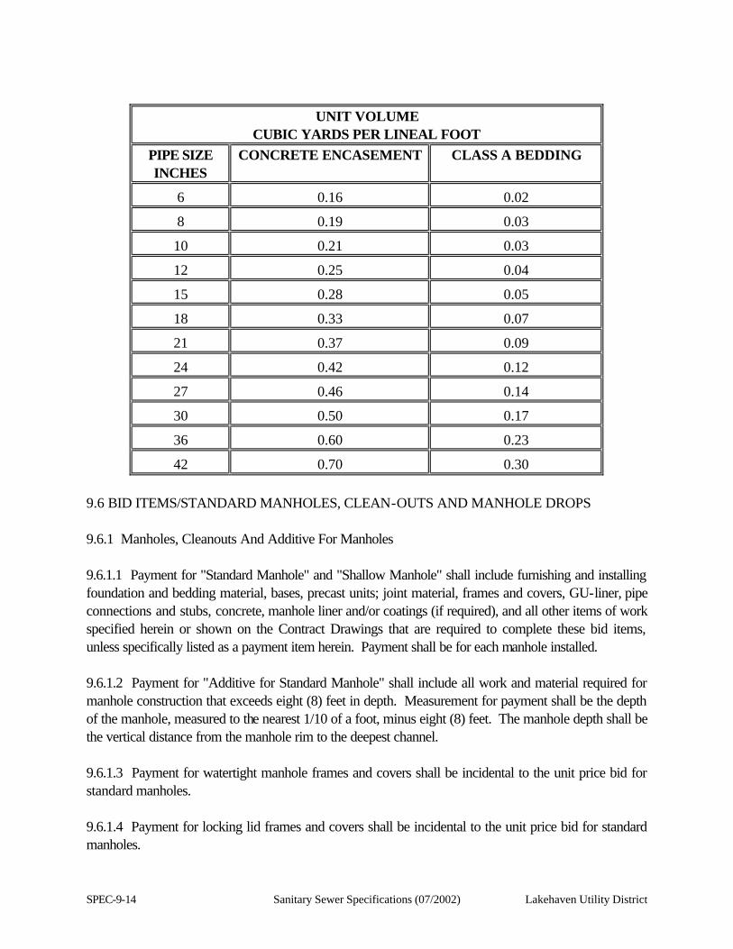
SPEC-9-14 Sanitary Sewer Specifications (07/2002) Lakehaven Utility District
UNIT VOLUME
CUBIC YARDS PER LINEAL FOOT PIPE SIZE INCHES
CONCRETE ENCASEMENT CLASS A BEDDING
6 0.16 0.02
8 0.19 0.03
10 0.21 0.03
12 0.25 0.04
15 0.28 0.05
18 0.33 0.07
21 0.37 0.09
24 0.42 0.12
27 0.46 0.14
30 0.50 0.17
36 0.60 0.23
42 0.70 0.30 9.6 BID ITEMS/STANDARD MANHOLES, CLEAN-OUTS AND MANHOLE DROPS 9.6.1 Manholes, Cleanouts And Additive For Manholes 9.6.1.1 Payment for "Standard Manhole" and "Shallow Manhole" shall include furnishing and installing foundation and bedding material, bases, precast units; joint material, frames and covers, GU-liner, pipe connections and stubs, concrete, manhole liner and/or coatings (if required), and all other items of work specified herein or shown on the Contract Drawings that are required to complete these bid items, unless specifically listed as a payment item herein. Payment shall be for each manhole installed. 9.6.1.2 Payment for "Additive for Standard Manhole" shall include all work and material required for manhole construction that exceeds eight (8) feet in depth. Measurement for payment shall be the depth of the manhole, measured to the nearest 1/10 of a foot, minus eight (8) feet. The manhole depth shall be the vertical distance from the manhole rim to the deepest channel. 9.6.1.3 Payment for watertight manhole frames and covers shall be incidental to the unit price bid for standard manholes. 9.6.1.4 Payment for locking lid frames and covers shall be incidental to the unit price bid for standard manholes.
Lakehaven Utility District Sanitary Sewer Specifications (07/2002) SPEC-9-15
9.6.1.5 Payment for sewer guards shall be incidental to the unit price bid for standard manholes. 9.6.2 Standard Drop Structures 9.6.2.1 Payment for standard drop structures (inside or outside drop structures) shall include furnishing and installing all pipe, fittings, concrete, backfill and its compaction, cleaning, testing installed piping, and all other items of work specified herein or shown on the Contract Drawings that are required to complete a drop structure. Payment for drop structures shall include the manhole. 9.6.2.2 Measurement for payment shall be the nearest 1/10 of a foot of drop structure height, measured between the invert elevations of the drop structure pipe openings into the manhole.
Lakehaven Utility District Sanitary Sewer Specifications (07/2002) SPEC-10-1
SECTION 10
GENERAL REQUIREMENTS FOR PUMP STATIONS 10.1 SUMMARY OF THE WORK 10.1.1 Description of the work. This section describes the work in general terms and special requirements for accomplishing it. The work consists of: 1. Construction of shored excavations and dewatering systems as necessary and required including
design, installation, operation, maintenance and removal of the dewatering discharge pipeline. 2. Construction of the cast-in-place reinforced concrete pump stations or pre-cast concrete
components for submersible pump stations. 3. Installation of station equipment and appurtenances. 4. Construction of above ground housings, as required. 5. Miscellaneous utility piping and site improvement. 10.1.2 The Contractor shall make provisions to comply with all requirements and obtain all necessary permits to complete the contracted work. 10.2 REGULATORY REQUIREMENTS 10.2.1 Description. This section includes but is not limited to the laws and codes by which the work has been designed. The Contractor's attention is directed to these laws and codes. Obtain copies and keep at Contractor's site office for duration of project. 10.2.1.1. Codes 1. Uniform Building Code - the most current as adopted by the local land use authority.
2. General Safety and Health Standards (Chapter 296-24 WAC or the most current addition adopted by Washington State).
3. Applicable Local Mechanical Code.
4. Applicable Local Plumbing Code.
5. The National and Local Electrical Codes.
6. National Fire Protection Association.
SPEC-10-2 Sanitary Sewer Specifications (07/2002) Lakehaven Utility District
7. Safety Standards for Construction Work (Chapter 296-155 WAC or the most current addition adopted by Washington State).
8. Other codes for specific applications are in the applicable technical sections. For example, a reference to the ASME Unfired Pressure Vessel Code could be contained in a technical section on air receivers.
10.3 ABBREVIATIONS 10.3.1 Description. This section summarizes the abbreviations and symbols used in the contract documents. 10.3.2 Abbreviations 10.3.2.1 Wherever Military Specifications (MIL), ANSI, ASTM, AASHTO, AISC, AWS, AWWA, Federal Specifications (FS), Manufacturers' Standardization Society (MSS), or other specifications are referred to in these Specifications without designation of year, the reference is to the current or revised specification effective at the time of receiving proposals. 10.3.2.2 Wherever the following terms are used, the intent and meaning shall be as follows: Abbreviation Stands For AASHTO American Association of State Highway and Transportation Officials ACI American Concrete Institute ABMA American Boiler Manufacturers Association ADC Air Diffusion Council AGA American Gas Association AGMA American Gear Manufacturers Association AIMA Acoustical and Insulating Materials Association AISC American Institute of Steel Construction AISI American Iron and Steel Institute AMCA Air Moving and Conditioning Association ANSI American National Standard Institute (formerly United States of America Standards
Institute) API American Petroleum Institute APWA American Public Works Association AREA American Railway Engineering Association ASCE American Society of Civil Engineers ASHRAE American Society of Heating, Refrigerating and Air Conditioning Engineers ASME American Society of Mechanical Engineers ASTM American Society for Testing and Materials AWI Architectural Woodwork Institute

Lakehaven Utility District Sanitary Sewer Specifications (07/2002) SPEC-10-3
AWPA American Wood Preservers' Association AWPI American Wood Preservers' Institute AWS American Welding Society AWWA American Water Works Association CAGI Compressed Air and Gas Institute CBM Certified Ballast Manufacturers CBR California Bearing Ratio CISPI Cast Iron Soil Pipe Institute CLFMI Chain Link Fencing Manufacturers Institute CMAA Crane Manufacturers Association of America CS Commercial Standard, US Department of Commerce CTI Cooling Tower Institute DFPA Douglas Fir Plywood Association EIA Electronic Industries Association EPA U. S. Environmental Protection Agency ETL Electrical Testing Laboratory Fed Spec Federal Specification FM Factory Mutual Insurance Company FPS Fluid Power Society FS Federal Specifications HI Hydraulic Institute HMI Hoist Manufacturers Institute IAMPO International Association of Plumbing and Mechanical Officials ICBO International Conference of Building Officials IEEE Institute of Electrical and Electronic Engineers IES Illuminating Engineering Society IPCE International Power Cable Engineers Association IPCEA Insulated Power Cable Engineers Association ISA Instrument Society of America MIL- Military Specification (leading symbol) NAPF National Association of Plastic Fabricators NBS National Bureau of Standards NEC National Electrical Code NEMA National Electrical Manufacturers Association NFPA National Fire Protection Association NSF National Sanitation Foundation OSHA Occupational Safety and Health Act PCA Portland Cement Association PDI Plumbing and Drainage Institute PS Product Standard, U.S. Department of Commerce SDI Steel Deck Institute SJI Steel Joist Institute SMACCNA Sheet Metal and Air Conditioning Contractors National Association
SPEC-10-4 Sanitary Sewer Specifications (07/2002) Lakehaven Utility District
SPR Simplified Practice Recommendations, U.S. Department of Commerce SSPC Structural Steel Painting Council UBC Uniform Building Code UL Underwriters Laboratories WCLIB West Coast Lumber Inspection Bureau WIC Woodwork Institute of California WISHA Washington Industrial Safety and Health Act WWPA Western Wood Products Association
Lakehaven Utility District Sanitary Sewer Specifications (07/2002) SPEC-11-1
SECTION 11
SITE WORK 11.1 SITE PREPARATION 11.1.1 Description. This section includes provisions for clearing, grubbing, stripping, demolition, disposal and related work necessary to prepare the site(s) for construction operations. 11.1.2 Execution 11.1.2.1 General. Unless otherwise noted on the Contract Drawings, the limits of clearing shall be determined by the Contractor and approved by the Engineer prior to beginning the work. Clearing shall be confined to the immediate vicinity of the construction, insofar as practicable, and shall not extend beyond the right-of-way, property, or easement lines shown on the Contract Drawings or as identified in the recorded easement document without the express written approval of the affected landowners and the Engineer. 11.1.2.2 Clearing. Portions of the project site where excavation is to be made, landscaping done or embankment is to be placed shall be cleared of all objectionable material such as brush, stumps and roots, grass and other vegetation, decayed vegetable matter, topsoil, rubbish, pavement, and other materials that may interfere with the proper execution of the work. Unless otherwise designated on the Contract Drawings, the Contractor shall not remove trees without authorization. Serious injuries to remaining trees that are not removed shall be avoided. Trees to be removed shall be felled within the clearing limits. Trees and vegetation to be left standing shall be protected from damage incident to site preparation and construction operations by the erection of barriers or by such other means as are required. 11.1.2.3 Grubbing. Grubbing shall consist of the removal and disposal of stumps, roots larger than three (3) inches in diameter, and matted roots from the construction areas. This material, together with logs and other organic or metallic debris not suitable for foundation purposes, shall be excavated and removed to a depth of not less than 18 inches below the original surface level of the ground in construction areas, such as areas for structures, pavement and shoulder areas. Depressions made by grubbing shall be filled with satisfactory and suitable material and compacted to make the surface conform to the original adjacent surface of the ground. 11.1.2.4. Stripping. The upper two (2) to six (6) inches of soil containing vegetation and root growth shall be stripped from areas to be excavated or from areas that will receive landscaping. The stripped material shall be removed from the site to an approved permitted disposal site in accordance with Section 11.1.2.6 of these Specifications and is approved by the Disposal Site Owner and the Engineer.
SPEC-11-2 Sanitary Sewer Specifications (07/2002) Lakehaven Utility District
11.1.2.5 Pavement Removal. Pavement to be removed shall be cut in neat, straight lines with vertical edges along the limits of pavement removal. Changes in removal width shall be made by cutting perpendicular and parallel to the centerline of the trench. The cut lines for removal of asphaltic or cement concrete pavement shall be approved by the Engineer in the field before cutting. 11.1.2.6 Disposal of Cleared Material. Cleared material shall be conveyed to a suitable waste site and disposed of in a manner that will meet all the requirements of the applicable Federal, State, County and City regulations. The waste site shall be provided by the Contractor at his/her expense and approved by the Waste Site Owner and the Engineer. 11.2 EARTHWORK 11.2.1 General 11.2.1.1 Description. The work of this section includes the furnishing of all labor, machinery, construction equipment, and any appurtenances required to perform in a workmanlike manner, all earthwork as shown on the Contract Drawings, specified herein, or as required. The major items of work covered in this section include, but shall not be limited to, the following: 1. Roadway Excavation and Backfill.
2. Structure Excavation and Backfill.
3. Foundation Material Installation. 11.2.1.2 Compaction. The maximum dry density and optimum moisture content of each soil type used in compacted fill shall be determined using ASTM D 1557. In situ densities may be determined using ASTM D 1556 or an approved nuclear device. 11.2.1.3 Regulatory Requirements. The Contractor must adhere to the requirements of the Washington State Industrial Safety and Health Act, RCW Chapter 49.17, Part N; EXCAVATION, TRENCHING, AND SHORING, Chapter 296-155, or the most current adopted of the Washington Administrative Code. These regulations relate to all excavations and contain specific requirements "to provide for the protection of all employees during all excavation work in connection with all construction work relating thereto, such as trenches, underpinning, shoring and bracing, and in connection with the construction of footings, foundations, retaining walls and other construction work below ground level." Excavation for structures shall be adequately supported to meet all requirements in the current rules, orders and regulations prescribed in the Safety Standards for Construction Work, Division of Industrial Safety and Health, Department of Labor and Industries, State of Washington. Excavation shall be adequately shored, braced and sheeted so that the earth will not slide or settle and so that all existing structures and all new structures will be fully protected from damage.
Lakehaven Utility District Sanitary Sewer Specifications (07/2002) SPEC-11-3
The support for excavation shall remain in place until the structure has been completed. During the backfilling of the structure, the shoring, sheeting, and bracing shall be carefully removed so that there shall be no caving, lateral movement, or flowing of the subsoils. 11.2.2 Products 11.2.2.1 Structural Backfill Material. The backfill shall be considered as all replaced excavation or new embankment adjacent to structures. It is the responsibility of the Contractor to stockpile the more desirable materials resulting from the excavation on the site for use in backfilling the various structures. In the event the Contractor is unable to find on the site or fails to reserve sufficient material to accomplish the backfilling, he shall furnish the additional material. Import material shall not contain more than five (5) percent by weight passing a No. 200 sieve and shall conform with Section 3.5.7 of the Lakehaven Utility District Sanitary Sewer Specifications. 11.2.2.2 Foundation Material. Gravel Base Class B shall conform to Section 3.5.7 of the Lakehaven Utility District Sanitary Sewer Specifications. 11.2.3 Execution 11.2.3.1 Roadway Excavation And Construction. Roadway excavation and construction shall conform to the applicable provisions of Section 7 of the Lakehaven Utility District Sanitary Sewer Specifications and in accordance with the details on the Contract Drawings. 11.2.3.2 Structure Excavation 11.2.3.2.1 All excavation for structures shall be done to the dimensions and levels indicated on the Contract Drawings or specified herein. Excavation shall be made to such width outside the lines of the structure to be constructed as may be required for proper working methods, the erection of forms and the protection of the work. 11.2.3.2.2 Care shall be taken to preserve the foundation surfaces shown on the Contract Drawings in an undisturbed condition. If the Contractor over excavates or disturbs the foundation surfaces shown on the Contract Drawings or specified herein, without written authorization of the Engineer, the Contractor shall replace such foundations with concrete fill or other material approved by the Engineer in a manner which will show by test an equal bearing power with the undisturbed foundation material. No additional payment will be made for the added quantity of concrete fill or other material used because of over excavation. 11.2.3.2.3 All excavation shall be kept free from water and all construction shall be carried on in the dry. Water shall be kept down until compacted fills and structures are complete to above water, safe from uplift and horizontal water pressure, and the backfill has been placed. 11.2.3.2.4 Inspection of Excavation: The Contractor shall notify the Engineer when excavation for
SPEC-11-4 Sanitary Sewer Specifications (07/2002) Lakehaven Utility District
compacted fill or structure is complete, and no forms, reinforcing steel or concrete shall be placed until the excavation has been inspected by the Engineer.
Lakehaven Utility District Sanitary Sewer Specifications (07/2002) SPEC-11-5
11.2.3.2.5 If the Contractor wishes to stockpile excavated material, he shall provide adequate facilities for drainage of water from the material and adequate facilities for handling of storm drainage from the area. 11.2.3.3 Structure Backfill - Backfill structures with Structural Backfill Material - The fill shall be placed in eight-inch (8") level, uniform layers measured before compaction. Compaction shall be with optimum water content and the compaction equipment shall be adequate to produce a minimum 95 percent relative compaction. 11.2.3.4 Preparation For Fill Construction. All surface soil shall be stripped to a minimum depth of six (6) inches. Unsuitable stripped material shall be removed from the site. Any soft zones encountered during stripping shall either be removed or treated as directed by the Engineer to provide a satisfactory working surface. After being stripped, the exposed surfaces shall be scarified to a depth of at least twelve (12) inches and compacted to at least 95 percent relative compaction. No fill shall be placed until prepared subgrade has been inspected. 11.2.3.5 Crushed Rock Under Structures. The Contractor shall place a layer not less than six (6) inches thick of Foundation Material compacted to 95 percent relative compaction, under structures to the lines, grades and thicknesses shown on the Contract Drawings. 11.3 TRENCHING, BACKFILLING AND COMPACTION 11.3.1 General. All trenching, shoring, foundation preparation, backfilling and compaction required to accomplish the work shown on the Contract Drawings or required by these Specifications shall be in accordance with the requirements and provisions of Section 3 of the Lakehaven Utility District Sanitary Sewer Specifications. 11.4 EXCAVATION SHORING 11.4.1. Description. The Contractor shall be solely responsible for the design, installation, and safety of any required shoring system. All shoring activity must comply with the requirements of the Washington State Industrial Safety and Health Act, RCW Chapter 49.17, Part N; EXCAVATION, TRENCHING, AND SHORING, Chapter 296-155, or the most current adopted of the Washington Administrative Code. These regulations relate to all excavation and contain specific requirements "to provide for the protection of all employees during all excavation work in connection with all construction work relating thereto, such as trenches, underpinning, shoring and bracing, and in connection with the construction of footings, foundations, retaining walls and other construction work below ground level." Prior to excavation or other work associated with this project, the Contractor shall be required to submit the following information to the Engineer. 1. Copies of all designed trench excavation, shoring and safety box installations;

SPEC-11-6 Sanitary Sewer Specifications (07/2002) Lakehaven Utility District
2. Certification for equipment and trench excavation required by WISHA or other agencies; and
3. Proof of compliance with the requirements of the State and other jurisdictions. Lakehaven Utility District is not responsible for enforcement of State requirements. Compliance with all State requirements is the responsibility of the Contractor. 11.5 DEWATERING 11.5.1 General 11.5.1.1 Description. This section describes the requirements associated with the installation and operation of a dewatering system for the construction of Pump Stations. Provide all wells, pumps, electrical equipment and power, discharge pipelines, permits and ultimate discharge point. Provide an emergency generator and automatic transfer switch with 5-day fuel tank to power the dewatering system during a power outage. Continue the operation of the dewatering system until the structure has attained concrete strength and has been backfilled. 11.5.1.2 System Description 11.5.1.2.1 Design required dewatering systems and arrange for the required discharge permits and installation of discharge pipelines to the point of discharge. 11.5.1.2.2 If the dewatering operation adversely affects local wells, the Contractor shall be responsible for resolving any conflicts with each affected property owner. 11.5.1.3 Submittals 11.5.1.3.1 Submit a plan showing the methods, materials, and equipment to be used to perform the dewatering of the pump station excavations. Provide the Engineer with a 100 scale (maximum) map showing the routing of the discharge pipelines. Provide a design for review prepared and signed by a consulting engineer registered in the State of Washington. 11.5.1.3.2 The State of Washington Department of Ecology has set restrictions on the amount and quality of discharges that may be discharged to any water course. Make provisions to comply with the requirements and obtain all necessary permits. 11.5.2 Components. Product components shall be chosen by the Contractor and submitted to the Engineer for review. If components are approved by the Engineer, they may be used on the project. 11.5.3 Execution 11.5.3.1 Vandalism. Design and install locking caps on each well to prevent vandalism.
Lakehaven Utility District Sanitary Sewer Specifications (07/2002) SPEC-11-7
11.5.3.2 Discharge Pipeline. Install the discharge pipeline in such a way that all driveways are passable.
SPEC-11-8 Sanitary Sewer Specifications (07/2002) Lakehaven Utility District
11.5.3.3 Disposal Of Excavation And Dewatering Water. Discharge of water to any water body or storm drainage systems shall comply with the following local, state and federal permitting and discharge requirement. 11.5.3.4 Dewatering System. Disposal of dewatering water shall be the sole responsibility of the Contractor. The Contractor may have to install a perimeter shoring system consisting of interlocking sheet piling or soldier piles and lagging, which may have to be pre-drilled. The Contractor may have to install a slurry or grout seal wall outside of this shoring and a bottom seal to limit inflow of water and prevent bottom blowout. It is the District's intent that the Contractor determine if the pump station site requires this dewatering effort and install a dewatering system which will only require pumping minor leakage through the installed dewatering system. 11.6 CHAINLINK FENCING 11.6.1 General 11.6.1.1 Description. This section sets forth the requirements for furnishing and installing an all chocolate brown or black (color), PVC-coated, chainlink fencing as indicated on the Contract Drawings. Chainlink fencing shall be eight (8) feet in height. Refer to Section 17.4 GALVANIZING, of these Specifications for requirements relating to galvanizing. Privacy slats shall be installed in all chainlink fencing to match the color of the fencing. 11.6.1.2 Standard Details. The Washington State Department of Transportation Standard Plan C-9 Type I Fence requirements shall be used. 11.6.2 Products. 11.6.2.1 Fabric. Use 9-gauge wire woven in a two (2) inch mesh with 15 mils of PVC chocolate brown or black (as approved by the District) coating over 0.3 ounces zinc substrate with an 850 pound breaking strength. Knuckle both selvages on fabric 60 inches high and under. Knuckle one (1) selvage and twist and barb other on fabrics greater than 60 inches high. Use 9-gauge PVC coated tie wires at not more than 24-inch spacing. 11.6.2.2. Line Posts. Line posts shall be two-inch (2") schedule 40 steel pipe. Galvanize and PVC coat. 11.6.2.3. Top And Brace Rail. The top and brace rails shall be 1-1/2 inch schedule 40 steel pipe. Provide six-inch (6") long top rail couplings spaced at not more than 21 feet. All top and brace rails shall be galvanized and PVC coated. 11.6.2.4 Terminal Posts. Terminal posts shall be three (3) inch schedule 40 steel pipe. Terminal posts galvanized and PVC coated.
Lakehaven Utility District Sanitary Sewer Specifications (07/2002) SPEC-11-9
11.6.2.5 Gates. Gate frames shall be constructed of not less than 1-1/2 inch inside diameter hot-dip galvanized pipe with a nominal weight of 2.72 pounds per lineal foot. The corners of the gate frame shall be fastened together and reinforced with a malleable iron to pressed steel fitting design. Cross trussing shall be 3/8-inch galvanized adjustable rods. The chain link fence fabric for filling the gate frame shall meet the fabric requirements specified in Section 11.6.2.1 of these Specifications. Each gate shall be furnished complete with necessary hinges, latch and drop bar locking device designed for the type of gateposts and gate. Gates shall have positive type latching devices with provisions for padlocking. 11.6.2.6 Framework. Hot-dip galvanize all fittings and hardware as described in ASTM A 153. Hot-dip galvanize all frames, and fabrications with a 2.0 ounce per square foot coating, per ASTM A 123 before color application. Coat the framework with thermal fusion coating of 15 mils PVC applied to manufacturer's specifications. 11.6.3 Execution 11.6.3.1 Post Setting. Set all line, terminal, and gate posts three (3) feet in the ground in 12 inch diameter concrete footings or attach to concrete deck with appropriate mounting hardware. The fence line shall conform to the ground profile. Provide 7-gauge bottom tension wire. 11.7 LANDSCAPING 11.7.1 Description. 1. This section covers the landscaping of the easement areas at pump stations as noted on the Contract
Drawings.
2. Fine grade easement areas as shown on the Contract Drawings assuring that all areas drain away from the pump station and valve vault hatches, the generator and the power panel.
3. Maintain all plants for the one (1) year guarantee period. 11.7.2 Soil 11.7.2.1 Fertilizers: Fertilizers for landscaping shall be pellet or granular formulations. 1. Type A: 6% nitrogen, 20% phosphorus, 20% potassium.
2. Type B: 11% nitrogen, 8% phosphorus, 4% potassium. 11.7.2.2. Soil Amendment. The soil amendment shall be shredded redwood, fir, or cedar particles graded from zero 0 to 1/4-inch with 15 percent maximum proportion of 1/4-inch particles, nitrogen stabilized (1-0-0), and salinity not more than 3.5. 11.7.2.3 Backfill Mixture. The backfill mixture shall contain one (1) part topsoil and one (1) part soil amendment thoroughly mixed, 1/2 pint iron sulfate, and 1/2 pint Type A fertilizer.
SPEC-11-10 Sanitary Sewer Specifications (07/2002) Lakehaven Utility District
11.7.2.4 Iron Sulfate. Iron sulfate shall be a dry formulation. 11.7.2.5 Tan Bark. Tan bark shall be dark in color, 3/4-inch to 1-inch in size, and fresh. 11.7.2.6 Plantings 1. Planting shall be as indicated on the Contract Drawings.
2. Provide healthy, shapely, well-rooted plants. Plant roots shall not be root-bound. 11.7.2.7 Systemic. Provide granular systemic with strength to keep weeds down for one (1) year. 11.7.3 Execution 11.7.3.1. Preparation 11.7.3.1.1 Thoroughly water all planting areas and confirm sprinkler coverage and operation. Soil shall be workable, wet and thoroughly cultivate to a depth of six (6) inches then allow to dry out. 11.7.3.1.2 Rocks: Remove all rocks over two (2) inches diameter in areas where ground cover or shrubbery will be planted. 11.7.3.1.3 Rake all areas to remove rocks, sticks, and debris. Drag to a smooth, even surface. Grade landscape areas so all swales drain to catch basins, streets, curbs, etc., to ensure proper surface drainage. 11.7.3.2 Placing Plantings 11.7.3.2.1 Dig pits circular in outline with vertical sides as follows: 1. Gallon size plants: 13-inch diameter with depth of pits as detailed on the Contract Drawings.
2. Five (5) gallon containers: 24-inch diameter with depth of pits as detailed on the Contract Drawings.
3. Fifteen (15) gallon containers: One-foot (1') wider than the diameter of the container with depth of pits as detailed on the Contract Drawings.
11.7.3.2.2 After the pits are dug, break the sides of the container open to allow root penetration. 11.7.3.2.3 Place plant in pit so the crown of the container is two (2) inches above the surrounding grade and backfill. Thoroughly mix backfill soil and conditioner with 1/2 pint of fertilizer for all fifteen (15) gallon and five (5) gallon container plants and 1/4 pint fertilizer for all one (1) gallon container plants.
Lakehaven Utility District Sanitary Sewer Specifications (07/2002) SPEC-11-11
11.7.3.2.4 The backfill shall be watered until saturated to the full depth of the hole. 11.7.3.2.5 Build basins around plants at container edge. Any plants that settle shall be raised to the specified level. 11.7.3.2.6 Mulch plant basins to a depth of one-inch (1") and water thoroughly. 11.7.3.2.7 Drive stakes, alongside root ball, two feet (2') deep into the ground prior to backfilling pits. Tie trees to the stakes at the halfway point and at the top by means of hose-covered wire. Securely nail the wire to the back of stakes and loop in a figure eight. 11.7.3.3 Plant Establishment Maintenance 11.7.3.3.1 General plant establishment shall immediately follow, coincide with, and be continuous during the planting operations, and shall continue for one (1) year. 11.7.3.3.2 Protect areas against all damage, including erosion and trespass, and provide proper safeguards. Maintain and keep in good repair all temporary barriers erected to prevent trespass. Check all barriers and temporary fencing daily, and make immediate repairs or replacements if required. 11.7.3.3.3 Repair all damage to planted areas, and replace plants immediately upon discovery of damage or loss. 11.7.3.3.4 Maintain constant moisture depth in soil to ensure vigorous growth. 11.7.3.3.5 Tree and shrub establishment: 1. During the entire maintenance period, maintain by regular watering, cultivating, weeding, repairing
stakes and typing, and spraying for insect pests. Prune trees and shrubs when requested.
2. Keep watering basins in good condition and weed-free at all times.
3. Fertilize each tree with Type B fertilizer prior to final acceptance with 1/4-pint and 1/2-pint of fertilizer for five (5) gallon and fifteen (15) gallon container trees, respectively. Spread fertilizer evenly over the surface of the plant basin and cultivate into mulch or soil. Thoroughly water after applying fertilizer.
4. All damaged, unhealthy or dead plants shall be replaced with new stock of the same kind and size indicated on the Contract Drawings.
11.7.3.3.6 Ground Cover Maintenance. Replace dead or dying plants immediately. Failure to replace plants may extend the length of the establishment period as deemed necessary by the Engineer. 11.7.3.4 Final Planting Inspection And Acceptance. Final inspection will be conducted upon
SPEC-11-12 Sanitary Sewer Specifications (07/2002) Lakehaven Utility District
completion of repairs, replacements, and corrective work. Five (5) days notice shall be given. Prior to being considered ready for inspection, the Contractor shall have done a final weeding and raking of all planting areas. Plant basins shall be repaired, and the job site cleaned of all debris and presented in a neat, orderly fashion. 11.7.3.5 Guarantee And Replacement 11.7.3.5.1. Guarantee all plants and plantings to be in a healthy, thriving condition until the end of the maintenance period or beyond that time until active growth is evident. Guarantee all trees against inherent defects and improper planting for one (1) year from date of acceptance. 11.7.3.5.2 Replace all dead plants and plants not in a vigorous condition as soon as directed by the Owner. Plants used for replacement must be of the same kind and size as indicated on the Contract Drawings and planted as outlined. 11.8 FLAGGERS, BARRICADES AND SIGNS 11.8.1 The Contractor shall be responsible for providing adequate flaggers, barricades, lights and signs for the protection of the work and the public at all times regardless of whether or not the flaggers, barricades, lights and signs are ordered by the Contractor. The Contractor and his/her surety shall be liable for injuries and damages to persons and property suffered by reason of the Contractor's operations or any negligence in connection therewith. 11.8.2 Flaggers, barricades, signs and traffic control furnished or provided shall conform to standards established in the latest adopted edition of "Manual on Uniform Traffic Control Devices" (MUTCD) published by the U.S. Department of Transportation.
Lakehaven Utility District Sanitary Sewer Specifications (07/2002) SPEC-12-1
SECTION 12
CONCRETE AND FINISHING 12.1 CAST-IN-PLACE CONCRETE 12.1.1 General 12.1.1.1 Description 12.1.1.1.1 Provide cast-in-place concrete work, complete as indicated, specified and required. Requirements specified in Section 10.2 and 10.3 form a part of this section. 12.1.1.1.2 Work Included in this section. Principal items are: 1. All cast-in-place concrete, including bases for mechanical and electrical equipment, sidewalks and
walkways and submersible pump stations.
2. Concrete shoring, form work, patching, grouting, sealants and crack repair.
3. Concrete curing. 12.1.1.2 Requirements Of Regulatory Agency. Unless specifically noted otherwise in this section, all work on concrete shall conform to the most current Uniform Building Code as adopted by the local land use authority. 12.1.1.3 Reference Standards. Where materials and methods are indicated in this section, or on the Contract Drawings, as being in conformance with a standard specification, it shall in all cases refer to the latest edition of that specification and shall include all interim revisions. Listing of a standard specification without further reference indicates that the particular material or method shall conform to such listed specifications. 12.1.1.4 Source Quality Control 12.1.1.4.1 General: All tests specified herein shall be performed at the Contractor's expense (except as noted), by an independent commercial testing laboratory and approved by the Engineer. 1. Sampling: Provide safe access to materials for sampling.
2. Submittals: Submit samples of aggregates to testing laboratory 45 days prior to initial concrete placement. Test results must be returned and approved by the Engineer prior to aggregate use and concrete placement.
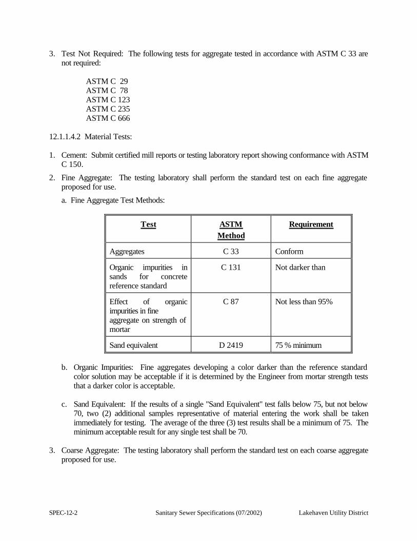
SPEC-12-2 Sanitary Sewer Specifications (07/2002) Lakehaven Utility District
3. Test Not Required: The following tests for aggregate tested in accordance with ASTM C 33 are not required:
ASTM C 29 ASTM C 78 ASTM C 123 ASTM C 235 ASTM C 666 12.1.1.4.2 Material Tests: 1. Cement: Submit certified mill reports or testing laboratory report showing conformance with ASTM
C 150.
2. Fine Aggregate: The testing laboratory shall perform the standard test on each fine aggregate proposed for use.
a. Fine Aggregate Test Methods:
Test
ASTM Method
Requirement
Aggregates
C 33
Conform
Organic impurities in sands for concrete reference standard
C 131
Not darker than
Effect of organic impurities in fine aggregate on strength of mortar
C 87
Not less than 95%
Sand equivalent
D 2419
75 % minimum
b. Organic Impurities: Fine aggregates developing a color darker than the reference standard
color solution may be acceptable if it is determined by the Engineer from mortar strength tests that a darker color is acceptable.
c. Sand Equivalent: If the results of a single "Sand Equivalent" test falls below 75, but not below
70, two (2) additional samples representative of material entering the work shall be taken immediately for testing. The average of the three (3) test results shall be a minimum of 75. The minimum acceptable result for any single test shall be 70.
3. Coarse Aggregate: The testing laboratory shall perform the standard test on each coarse aggregate
proposed for use.
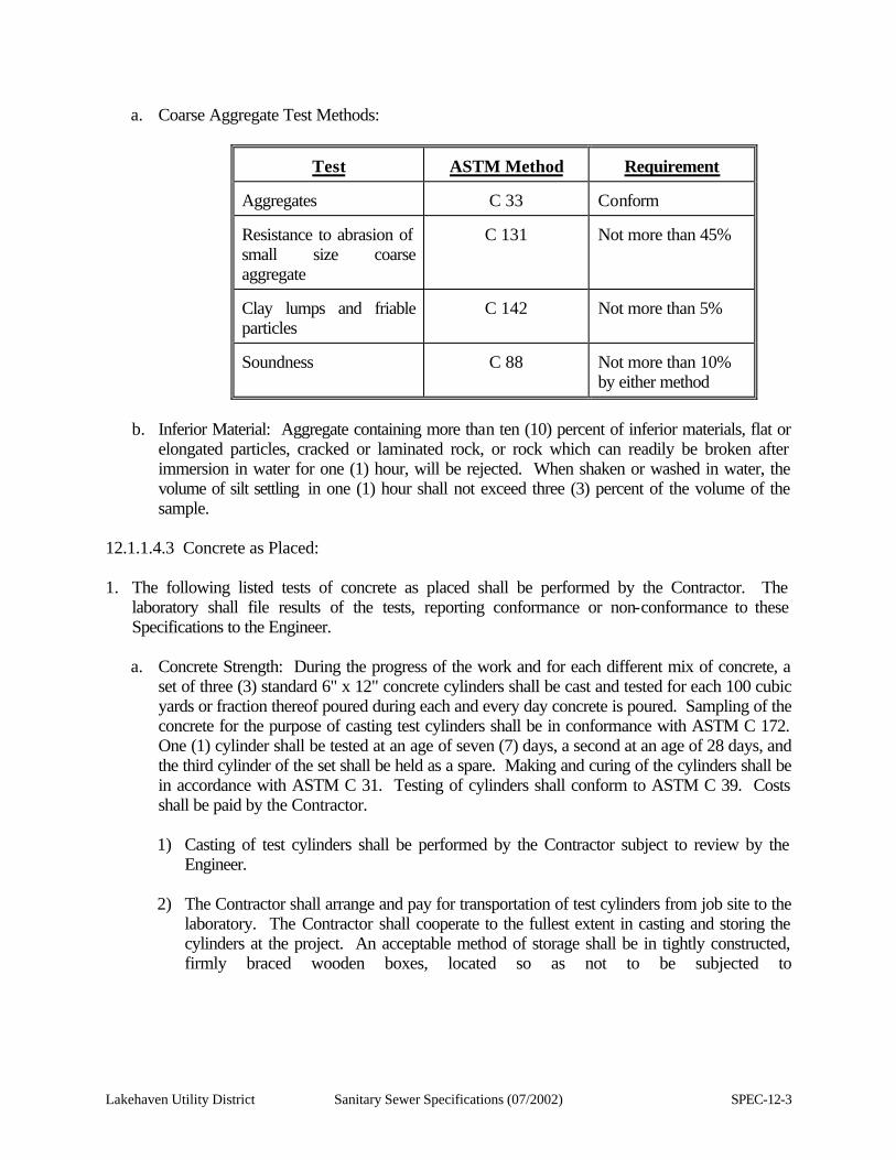
Lakehaven Utility District Sanitary Sewer Specifications (07/2002) SPEC-12-3
a. Coarse Aggregate Test Methods:
Test
ASTM Method
Requirement
Aggregates
C 33
Conform
Resistance to abrasion of small size coarse aggregate
C 131
Not more than 45%
Clay lumps and friable particles
C 142
Not more than 5%
Soundness
C 88
Not more than 10% by either method
b. Inferior Material: Aggregate containing more than ten (10) percent of inferior materials, flat or
elongated particles, cracked or laminated rock, or rock which can readily be broken after immersion in water for one (1) hour, will be rejected. When shaken or washed in water, the volume of silt settling in one (1) hour shall not exceed three (3) percent of the volume of the sample.
12.1.1.4.3 Concrete as Placed: 1. The following listed tests of concrete as placed shall be performed by the Contractor. The
laboratory shall file results of the tests, reporting conformance or non-conformance to these Specifications to the Engineer. a. Concrete Strength: During the progress of the work and for each different mix of concrete, a
set of three (3) standard 6" x 12" concrete cylinders shall be cast and tested for each 100 cubic yards or fraction thereof poured during each and every day concrete is poured. Sampling of the concrete for the purpose of casting test cylinders shall be in conformance with ASTM C 172. One (1) cylinder shall be tested at an age of seven (7) days, a second at an age of 28 days, and the third cylinder of the set shall be held as a spare. Making and curing of the cylinders shall be in accordance with ASTM C 31. Testing of cylinders shall conform to ASTM C 39. Costs shall be paid by the Contractor. 1) Casting of test cylinders shall be performed by the Contractor subject to review by the
Engineer.
2) The Contractor shall arrange and pay for transportation of test cylinders from job site to the laboratory. The Contractor shall cooperate to the fullest extent in casting and storing the cylinders at the project. An acceptable method of storage shall be in tightly constructed, firmly braced wooden boxes, located so as not to be subjected to
SPEC-12-4 Sanitary Sewer Specifications (07/2002) Lakehaven Utility District
vibrations. The box shall be constructed or equipped so as to keep the temperature immediately adjacent to the specimens between 60 and 80 degrees F and to prevent loss of moisture. Other methods may be used, subject to approval by the Engineer.
b. Slump: For every 50 cubic yards of concrete placed, a slump test shall be made in accordance
with ASTM C 143. The slump shall be within the limits of two (2) to four (4) inches at point of delivery. Non-conformance to these limits subjects the concrete to possible rejection. The Engineer or his/her representative shall be the sole judge with respect to rejection. A higher slump, not to exceed 6-1/2 inches may be acceptable when special admixtures, which have been approved by the Engineer, are utilized in the advance design mix submitted as per Section 12.1.1.5 of these specifications. A slump test shall be made on each sample of concrete taken for test cylinders. Slump tests shall be taken by Engineer's representative.
c. Additional Tests: In all cases that the test results of concrete cylinders or concrete materials
submitted for use fail to meet the appropriate requirements specified, the Contractor shall provide for additional tests on new specimens. If, in the opinion of the Engineer, results of tests on concrete cylinders indicate the possibility of sub-standard concrete in the structure, the Engineer may require cored samples taken from the concrete. The coring and testing shall conform to ASTM C 42. All costs for these additional tests shall be paid by the Contractor. If, in the opinion of the Engineer, the results of the core tests indicate that concrete has been placed which does not meet this specification, the defective concrete shall be removed and replaced, at the Contractor's expense.
12.1.1.5 Advance Design Of Concrete Mixes 12.1.1.5.1 The Contractor, at his/her own expense, shall employ an independent commercial testing laboratory approved by the Engineer to design all concrete mixes. The mixes shall be designed and trial batched far enough ahead of concrete pours to allow completion of trial batch test cylinders; and to submit the test results and the mix design to the Engineer for approval. 12.1.1.5.2 The Contractor is solely responsible for selection of a laboratory, submittal of materials to the laboratory in time for all tests, and overall timing of all aspects of testing program, including submittals. 12.1.1.5.3 The mix shall be so designed that the 28-day strength of any test cylinder shall not be less than 3000 psi. The minimum amount of cement per cubic yard of concrete shall be six (6) sacks. 12.1.1.5.4 Concrete shall consist of a mixture of Portland Cement, fine aggregate, coarse aggregate, water, air entraining agent and a water reducing agent. The air entraining agent shall produce five (5) percent entrained air, plus or minus one (1) percent, except for slabs finished
Lakehaven Utility District Sanitary Sewer Specifications (07/2002) SPEC-12-5
with color hardeners, for which the percentage of air entrainment shall not exceed two (2) percent unless approved by the supplier of the hardener. The Contractor is cautioned to be sure that the percentage of air entrainment is correct for concrete placed in slabs with color hardener. 12.1.1.5.5 Cement, aggregates and water shall be proportioned by weight. 12.1.1.5.6 No chlorides shall be used in any concrete mix. 12.1.1.5.7 In proportioning aggregates and water, compensation shall be made for the weight of moisture in the aggregates (which shall be determined periodically). 12.1.1.6 Material Storage 12.1.1.6.1 Cement: Any cement stored on the project site, immediately upon receipt of the shipment shall be stored in a dry, weather-tight, properly ventilated structure, with adequate provisions for prevention of moisture absorption and overheating of the cement. 12.1.1.6.2 Aggregates: Any aggregates stored on the project site, shall be stored in piles which afford good drainage and which are so protected so as to prevent the inclusion of foreign material. The various sizes or gradations of aggregates shall be stockpiled separately. 12.1.1.6.3 Lumber: All lumber, including plywood for forms, shall be stored so as to prevent direct contact with the ground. The stored lumber shall be protected from the elements by a suitable covering, such as polyethylene film or waterproof building paper, suitably held in place. 12.1.1.7 Submittal Of Shop Drawings, Samples And Descriptive Details 12.1.1.7.1 General: The Contractor shall submit to the Engineer for review the following, even though items proposed to be furnished conform to the exact description stated in this section, or as shown on the Contract Drawings. 1. A notarized statement that the cement conforms to ASTM C 150. If such a statement is not
possible, the cement shall be tested as noted subsequently in this Specification under "Material Tests".
2. Manufacturer's descriptive details or samples of the following, when item is specified in this section.
a. Admixtures.
b. Joint materials, including sealants.
c. Curing materials and curing program.
d. Non-shrink non-metallic grout.
e. Epoxy compounds or grouts, including epoxy adhesive compound.
f. Form ties.
g. Form coatings.
h. Forms, if fabricated off construction site.
SPEC-12-6 Sanitary Sewer Specifications (07/2002) Lakehaven Utility District
i. Sample of forms for textured concrete, when specified or when shown on the Contract Drawings.
3. Construction joint layout.
4. Program and method of concrete placement.
12.1.1.8 Architectural Concrete. All interior and exterior concrete which is exposed such as surfaces of walls, beams, columns and ceiling, is hereby designated as "Architectural Concrete" and shall receive a Class 2 Surface Finish for Vertical and Horizontal Formed Surfaces. The interior wall and ceiling surfaces of tanks, wet wells and channels shall not be considered Architectural Concrete, unless specifically specified otherwise. 12.1.1.9 Ready-Mix Concrete 12.1.1.9.1 Should the Contractor elect to use ready-mix concrete for the project, the concrete shall be supplied by a ready-mix plant that is certified by the National Ready-Mix Concrete Association. The Contractor shall submit verification of this certification to the Engineer. 12.1.1.9.2 If the concrete supplier is not certified by the National Ready-Mix Concrete Association, he/she may qualify for supplying concrete by conforming to the following requirements: 1. Ready-mixed concrete may be produced by stationary mixers or truck mixers. Agitation of the
concrete subsequent to mixing may be done by truck mixers or truck agitators. Each mixer and agitator shall have attached thereto in a prominent place, a metal plate or plates on which is plainly marked, for the various uses for which the equipment is designed, the capacity of the drum or container in terms of the volume of mixed concrete and the speed of rotation of the mixing drum or blades. Stationary mixers shall be equipped with an acceptable timing device that will not permit the batch to be discharged until the specified mixing time has elapsed. Truck mixers or agitators transporting central-mixed, shrink-mixed, or transit-mixed concrete shall be equipped with a non-resettable counter for recording the number of revolutions of the drum, blades or paddles.
2. The mixer, when loaded to capacity, shall be capable of combining the ingredients of the concrete within the specified time into a thoroughly mixed and uniform mass and of discharging the concrete with a satisfactory degree of uniformity.
3. The agitator, when loaded to capacity, shall be capable of maintaining the mixed concrete in a thoroughly mixed and uniform mass and of discharging the concrete with a satisfactory degree of uniformity.
4. Slump tests may be made of individual samples taken at approximately the 1/4 and 3/4 points of the load and if the slumps differ by more than two (2) inches, the mixer or agitator shall not be used until the condition is corrected. If the slump test is not satisfactorily met by mixers when operated during the minimum specified mixing time and loaded to capacity, or
Lakehaven Utility District Sanitary Sewer Specifications (07/2002) SPEC-12-7
by agitators when loaded to capacity, the equipment may still be used when operation with a longer mixing time or with a smaller load will produce concrete that will meet the slump tests.
5. Ready-mixed concrete shall be mixed and delivered by means of one (1) of the following combinations of operations:
a. Mixed completely in a stationary mixer and the mixed concrete transported to the point of delivery in a truck agitator or in a truck mixer operating at agitator speed (known as central-mixed concrete).
b. Mixed partially in a stationary mixer and the mixing completed in a truck mixer (known as shrink-mixed concrete).
c. Mixed completely in a truck mixer (known as transit-mixed concrete).
6. The mixing may be performed under the surveillance of a representative of the Engineer, either at the plant site or at the jobsite.
7. Mixers and agitators shall be operated within the limits of capacity and speed of rotation designated by the manufacturer of the equipment.
8. When a stationary mixer is used for partial mixing of the concrete (shrink-mixing), the mixing time in the stationary mixer may be reduced to the minimum required to intermingle the ingredients (about 30 seconds).
9. When a truck mixer is used either for complete mixing or to finish the partial mixing done in a stationary mixer, each batch of concrete shall be mixed for not less than 70 nor more than 100 revolutions of the drum or blades at the rate of rotation designated by the manufacturer of the equipment as mixing speed. If any additional mixing is done, it shall be at the speed designated by the manufacturer of the equipment as agitating speed.
10. When a truck mixer or truck agitator is used for transporting concrete that has been completely mixed in a stationary mixer, mixing during transportation shall be at the speed designated by the manufacturer of the equipment as agitating speed.
11. When a truck mixer or agitator is used for transporting concrete, the concrete shall be delivered to the site of the work and discharge shall be completed within 1-1/2 hours after the introduction of the cement to the mix. In hot weather or under conditions contributing to quick stiffening of the concrete, a delivery time of less than 1-1/2 hours may be required. When a truck mixer is used for the complete mixing of the concrete, a delivery time of less than 1-1/2 hours may be required. When a truck mixer is used for the complete mixing of the concrete, the mixing operation shall begin within 30 minutes after the cement has been intermixed with the aggregates. Concrete transported in a truck mixer or agitator shall not have been subjected to more than 250 revolutions of the drum or blades at the time it is placed in the work. Intermittent agitation of the concrete will be permitted in order to stay below the maximum of 250 revolutions provided that the time limit of 1-1/2 hours after the introduction of the cement to the mix is not exceeded.
12. The organization supplying concrete shall have sufficient plant capacity and transporting apparatus to ensure continuous delivery at the rate required. The rate of delivery of concrete
SPEC-12-8 Sanitary Sewer Specifications (07/2002) Lakehaven Utility District
shall be such as to provide for the proper placing of the concrete. The methods of delivering and handling the concrete shall be such as will facilitate placing with a minimum of rehandling and without damage to the structure or the concrete.
12.1.2 Products 12.1.2.1 General. All materials shall be furnished by an established and experienced manufacturer or supplier. All materials shall be new, of first-class ingredients and guaranteed to perform the service required. 12.1.2.2 Concrete Materials 12.1.2.2.1 Portland Cement, unless noted otherwise in this section, shall be Type II and shall conform to ASTM C 150; it shall meet the requirements of low alkali cement in conformance with Table 1A of ASTM C 150. Only one (1) brand of cement shall be used for concrete placed on the project, unless a change in brand is approved in writing by the Engineer. 12.1.2.2.2 Concrete Aggregates (General): 1. Concrete aggregates shall be free from deleterious coatings, clay balls, roots, bark, sticks, rags and
other extraneous materials, and shall be thoroughly and uniformly washed before use.
2. Unless noted otherwise in this section, or unless the Contractor's request for use of smaller aggregate has been approved by the Engineer concrete aggregate shall be 1-1/2-inch maximum size for all concrete on the project, except for thin sections, such as slabs or walls ten (10) inches thick, or less, or for sections which require special placement due to shape, form or density of reinforcing, in which case, maximum size shall be 3/4-inch nominal.
12.1.2.2.3 Coarse Aggregate: 1. General: Coarse aggregate shall consist of clean, hard, durable gravel, crushed gravel, crushed
rock, or combinations thereof.
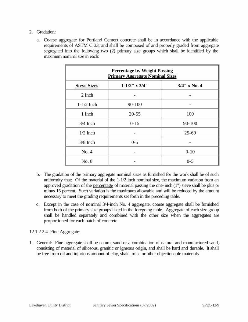
Lakehaven Utility District Sanitary Sewer Specifications (07/2002) SPEC-12-9
2. Gradation:
a. Coarse aggregate for Portland Cement concrete shall be in accordance with the applicable requirements of ASTM C 33, and shall be composed of and properly graded from aggregate segregated into the following two (2) primary size groups which shall be identified by the maximum nominal size in each:
Percentage by Weight Passing Primary Aggregate Nominal Sizes
Sieve Sizes
1-1/2" x 3/4"
3/4" x No. 4
2 Inch
-
-
1-1/2 Inch
90-100
-
1 Inch
20-55
100
3/4 Inch
0-15
90-100
1/2 Inch
-
25-60
3/8 Inch
0-5
-
No. 4
-
0-10
No. 8
-
0-5
b. The gradation of the primary aggregate nominal sizes as furnished for the work shall be of such
uniformity that: Of the material of the 1-1/2 inch nominal size, the maximum variation from an approved gradation of the percentage of material passing the one-inch (1") sieve shall be plus or minus 15 percent. Such variation is the maximum allowable and will be reduced by the amount necessary to meet the grading requirements set forth in the preceding table.
c. Except in the case of nominal 3/4-inch No. 4 aggregate, coarse aggregate shall be furnished from both of the primary size groups listed in the foregoing table. Aggregate of each size group shall be handled separately and combined with the other size when the aggregates are proportioned for each batch of concrete.
12.1.2.2.4 Fine Aggregate: 1. General: Fine aggregate shall be natural sand or a combination of natural and manufactured sand,
consisting of material of siliceous, granitic or igneous origin, and shall be hard and durable. It shall be free from oil and injurious amount of clay, shale, mica or other objectionable materials.
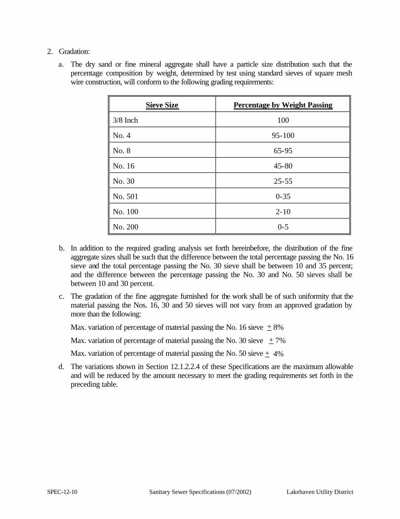
SPEC-12-10 Sanitary Sewer Specifications (07/2002) Lakehaven Utility District
2. Gradation:
a. The dry sand or fine mineral aggregate shall have a particle size distribution such that the percentage composition by weight, determined by test using standard sieves of square mesh wire construction, will conform to the following grading requirements:
Sieve Size
Percentage by Weight Passing 3/8 Inch
100
No. 4
95-100
No. 8
65-95
No. 16
45-80
No. 30
25-55
No. 501
0-35
No. 100
2-10
No. 200
0-5
b. In addition to the required grading analysis set forth hereinbefore, the distribution of the fine
aggregate sizes shall be such that the difference between the total percentage passing the No. 16 sieve and the total percentage passing the No. 30 sieve shall be between 10 and 35 percent; and the difference between the percentage passing the No. 30 and No. 50 sieves shall be between 10 and 30 percent.
c. The gradation of the fine aggregate furnished for the work shall be of such uniformity that the material passing the Nos. 16, 30 and 50 sieves will not vary from an approved gradation by more than the following:
Max. variation of percentage of material passing the No. 16 sieve + 8%
Max. variation of percentage of material passing the No. 30 sieve + 7%
Max. variation of percentage of material passing the No. 50 sieve + 4%
d. The variations shown in Section 12.1.2.2.4 of these Specifications are the maximum allowable and will be reduced by the amount necessary to meet the grading requirements set forth in the preceding table.
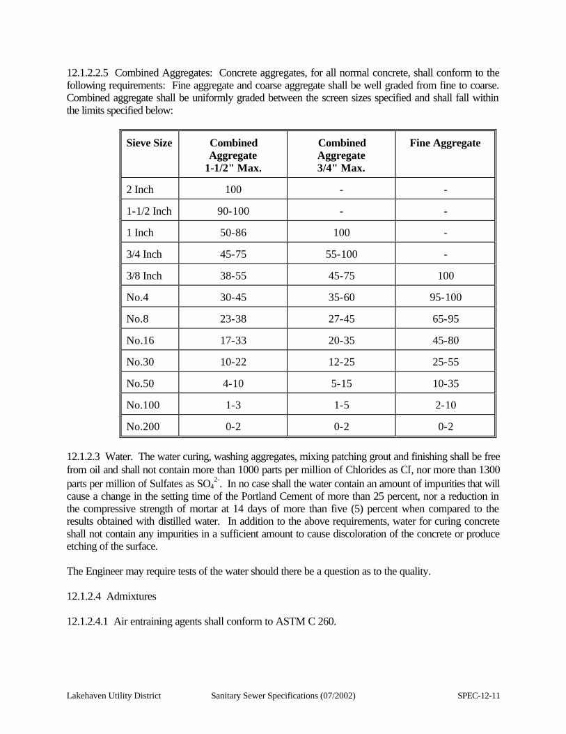
Lakehaven Utility District Sanitary Sewer Specifications (07/2002) SPEC-12-11
12.1.2.2.5 Combined Aggregates: Concrete aggregates, for all normal concrete, shall conform to the following requirements: Fine aggregate and coarse aggregate shall be well graded from fine to coarse. Combined aggregate shall be uniformly graded between the screen sizes specified and shall fall within the limits specified below:
Sieve Size
Combined Aggregate
1-1/2" Max.
Combined Aggregate 3/4" Max.
Fine Aggregate
2 Inch
100
-
-
1-1/2 Inch
90-100
-
-
1 Inch
50-86
100
-
3/4 Inch
45-75
55-100
-
3/8 Inch
38-55
45-75
100
No.4
30-45
35-60
95-100
No.8
23-38
27-45
65-95
No.16
17-33
20-35
45-80
No.30
10-22
12-25
25-55
No.50
4-10
5-15
10-35
No.100
1-3
1-5
2-10
No.200
0-2
0-2
0-2
12.1.2.3 Water. The water curing, washing aggregates, mixing patching grout and finishing shall be free from oil and shall not contain more than 1000 parts per million of Chlorides as Cl-, nor more than 1300 parts per million of Sulfates as SO4
2-. In no case shall the water contain an amount of impurities that will cause a change in the setting time of the Portland Cement of more than 25 percent, nor a reduction in the compressive strength of mortar at 14 days of more than five (5) percent when compared to the results obtained with distilled water. In addition to the above requirements, water for curing concrete shall not contain any impurities in a sufficient amount to cause discoloration of the concrete or produce etching of the surface. The Engineer may require tests of the water should there be a question as to the quality. 12.1.2.4 Admixtures 12.1.2.4.1 Air entraining agents shall conform to ASTM C 260.
SPEC-12-12 Sanitary Sewer Specifications (07/2002) Lakehaven Utility District
12.1.2.4.2 The water reducing admixture shall conform to ASTM C 494, Type A, or Type F when approved by the Engineer. 12.1.2.4.3 No other admixtures shall be used unless specifically approved by the Engineer in writing. Both admixtures shall be added to concrete mix ingredients in liquid form by means of a special dispensing unit, approved by the manufacturer of the admixture as suitable for accurately dispensing the admixtures. The dispensing unit shall be equipped with suitable devices that indicate proper operation of the unit to the batch plant operator. An alarm or indicator shall be installed which will immediately inform the batch plant operator if the dispensing unit malfunctions. Equipment shall be designed so that its accuracy can be checked conveniently. Admixtures shall be dispensed uniformly into the mixing water as it is added to the concrete batch. The strength of the concrete containing the admixture (used in the amount recommended by the manufacturer for the mixes to be used on this project) shall, at the age of 48 hours and longer, be not less than that of similar concrete without the admixture. Data on admixtures shall be submitted to the Engineer for approval prior to use of the admixture in the concrete mix. 12.1.2.4.4 No admixture containing any chloride ions is acceptable. 12.1.2.5 Dry Pack Grout. The dry pack grout shall be very stiff mix grout, consisting of one (1) part Portland Cement to two (2) parts sand (by weight) and water. The mixture shall be wetted only sufficiently to moisten the materials to the point where they will ball when squeezed by hand. 12.1.2.6 Cement Mortar. Cement mortar shall consist of one (1) part Portland Cement, two (2) parts fine sand (by weight) and water. The amount of water shall be only that needed to make the mix workable for the intended use. The cement shall be a mixture of white and regular cements as may be required to make a mortar that when cured 28 days will match the adjacent concrete. Prepare several trial batches and make test samples in an inconspicuous location for review and approval of the Engineer. When a mix has been selected for color match, batch all mortar by weight in accordance with the formula for the selected mix. 12.1.2.7 White Cement. Where white cement is used for patching, it shall be one (1) of the following: 1. Ideal White cement, manufactured by Ideal Cement Co., Houston, Texas.
2. Riverside White Cement, manufactured by Riverside Div. of American Cement Corp., Crestmore,
California.
3. Trinity White Cement, manufactured by Trinity Div. of General Portland Cement Co., Houston, Texas.
12.1.2.8 Epoxy Adhesive Compound. Epoxy adhesive compound shall be Sikadur epoxy adhesives as manufactured by the Sika Chemical Corporation, Concresive compounds manufactured by the Adhesive Engineering Company or an Approved Equal. Compounds shall be suitable for the specific use.
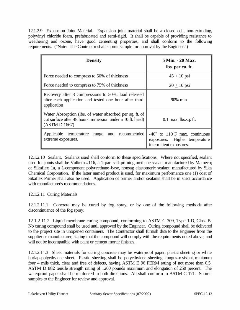
Lakehaven Utility District Sanitary Sewer Specifications (07/2002) SPEC-12-13
12.1.2.9 Expansion Joint Material. Expansion joint material shall be a closed cell, non-extruding, polyvinyl chloride foam, prefabricated and semi-rigid. It shall be capable of providing resistance to weathering and ozone, have good cementing properties, and shall conform to the following requirements. ("Note: The Contractor shall submit sample for approval by the Engineer.")
Density
5 Min. - 20 Max.
lbs. per cu. ft. Force needed to compress to 50% of thickness
45 + 10 psi
Force needed to compress to 75% of thickness
20 + 10 psi
Recovery after 3 compressions to 50%; load released after each application and tested one hour after third application
90% min.
Water Absorption (lbs. of water absorbed per sq. ft. of cut surface after 48 hours immersion under a 10 ft. head) (ASTM D 1667)
0.1 max. lbs.sq. ft.
Applicable temperature range and recommended extreme exposures.
-40o to 110oF max. continuous exposures. Higher temperature intermittent exposures.
12.1.2.10 Sealant. Sealants used shall conform to these specifications. Where not specified, sealant used for joints shall be Vulkem #116, a 1-part self-priming urethane sealant manufactured by Mameco; or Sikaflex 1a, a 1-component polyurethane-base, nonsag elastomeric sealant, manufactured by Sika Chemical Corporation. If the latter named product is used, for maximum performance one (1) coat of Sikaflex Primer shall also be used. Application of primer and/or sealants shall be in strict accordance with manufacturer's recommendations. 12.1.2.11 Curing Materials 12.1.2.11.1 Concrete may be cured by fog spray, or by one of the following methods after discontinuance of the fog spray. 12.1.2.11.2 Liquid membrane curing compound, conforming to ASTM C 309, Type 1-D, Class B. No curing compound shall be used until approved by the Engineer. Curing compound shall be delivered to the project site in unopened containers. The Contractor shall furnish data to the Engineer from the supplier or manufacturer, stating that the compound will comply with the requirements noted above, and will not be incompatible with paint or cement mortar finishes. 12.1.2.11.3 Sheet materials for curing concrete may be waterproof paper, plastic sheeting or white burlap-polyethylene sheet. Plastic sheeting shall be polyethylene sheeting, fungus-resistant, minimum four 4 mils thick, clear and free of defects, having ASTM E 96 PERM rating of not more than 0.5, ASTM D 882 tensile strength rating of 1200 pounds maximum and elongation of 250 percent. The waterproof paper shall be reinforced in both directions. All shall conform to ASTM C 171. Submit samples to the Engineer for review and approval.
SPEC-12-14 Sanitary Sewer Specifications (07/2002) Lakehaven Utility District
12.1.2.11.4 Wet blankets shall be made of clean cotton mats (burlap is unacceptable). The material shall be free from any substance that will have a deleterious effect on the concrete. Mats shall have a thickness sufficient to retain moisture between programmed applications of water. 12.1.2.12 Forms. Forms shall be of wood, unless noted otherwise, or unless the Engineer approves a request to use other materials. 12.1.2.12.1 Plywood form lumber shall have a minimum thickness of 5/8 inch and shall be five (5) ply, Class 1, exterior "Plyform" DFPA. Surfaces shall be B-B minimum grade. High density overlaid panels, or panels of similar construction, may be used subject to approval by the Engineer. Plywood forms shall be used for all exposed surfaces. "Exposed Concrete" shall be all concrete exposed to view, including the entire exterior and interior concrete surface of walls, beams, columns, slabs, and all walls of tanks, chambers, wells, and tunnels, except where any of the above are in contact with earth. All plywood shall conform to U.S. Product Standard PS-1. 12.1.2.12.2 Forms for "Textured Concrete" shall produce the texture required elsewhere. Forms may be plywood with shape of wood strips attached to their liner face or plywood forms may be lined with plastic form liners. 12.1.2.13 Form Coating Compounds. Form coating compounds shall not stain or impart any material or residue to the concrete surface detrimental or incompatible with any specified paint system to be applied later. The Contractor shall furnish a letter to the Engineer from the compound manufacturer stating that the material proposed meets this requirement. No form coating shall be used without first receiving approval by the Engineer. 12.1.2.14 Chemical Hardener For Concrete. The chemical hardener for concrete will consist of a polymerized solution of natural chlorinated rubber and epoxy resins containing no wax, oil or silicone materials, containing 18 percent solids, meeting ASTM C 309 Type 1. The chemical hardener shall be P-C/PROCO CRETE as manufactured by P-C Western Chemicals, Inc. Or an Approved Equal. 12.1.2.15 Non-Shrink Grout. Non-shrink, non-metallic grout, should it be shown on the Contract Drawings, or as specified. Use dimensionally stable, inorganic, premixed, and resistant to acids, alkalis, saltwater, unaffected by water and oil. Use grout having high strength even when used as a pourable mixture, bonding well with steel and cured concrete or be compatible with a suitable bonding agent used to effect the bond. Use grout in strict accordance with the manufacturer's recommendations. Non-shrink grout used shall be Five Star grout as manufactured by U.S. Grout Corporation, Bonsal Construction Grout as manufactured by Bonsal Co., or an Approved Equal. See also Section 12.4 of these Specifications.
Lakehaven Utility District Sanitary Sewer Specifications (07/2002) SPEC-12-15
12.1.3 Execution 12.1.3.1 Proportioning Concrete Materials. Concrete shall be proportioned by weight as specified in this section. No concrete shall be placed prior to approval by the Engineer of submittals for reinforcing steel and other materials specified in this section and of the mix proposed. Unfavorable results of actual pours may necessitate a redesign of mixes. 12.1.3.2 Batching And Mixing Concrete Materials 12.1.3.2.1 The mixing and transporting equipment shall be of a approved type, or ready mix equipment conforming to ASTM C 94 and shall have been certified by the National Ready-Mix Concrete Association. See Section 12.1.1.9, Ready-Mix Concrete, of these Specifications. It shall be capable of combining aggregates, cement and water, within the specified time, into a thoroughly mixed and uniform mass, and of discharging the mixture without segregation. The materials of one (1) batch shall be completely discharged before the mixer is recharged. 12.1.3.2.2 No cement having a temperature exceeding 160 degrees F shall be used in any batch. 12.1.3.2.3 Mixing may be performed at the site, subject to approval of mixing equipment and methods by the Engineer, or may be ready or transit mixed. 12.1.3.2.4 Ready or Transit Mixed Concrete and Mortar: 12.1.3.2.4.1 Ready or transit mixed concrete and mortar shall be completely mixed when delivered to the project site. 12.1.3.2.4.2 No additional mixing water shall be incorporated into the concrete or mortar during hauling. Water may be added after delivery only when ordered by the Engineer or his/her representative. Should water be added, the mixing drum shall be revolved not less than 30 revolutions at mixing speed after the water is added and before discharge is commenced. 12.1.3.2.4.3 Each load of ready-mixed concrete or mortar delivered at the job site, unless otherwise ordered by the Engineer, shall be accompanied by a ticket showing mix design number, volume of concrete or mortar, the weight of cement in pounds and the total weight of all ingredients in pounds. The ticket shall also show the time of day at which the materials were batched and the reading of the revolution counter at the time the truck mixer was charged. 12.1.3.2.4.4 The retempering of any concrete or mortar that has partially hardened, that is, mixing with or without additional cement, aggregate or water, will not be permitted, and such partially hardened concrete or mortar shall not be used in the work. 12.1.3.2.4.5 Concrete shall be deposited in the forms within the time specified in Section 12.1.1.9 of these Specifications.
SPEC-12-16 Sanitary Sewer Specifications (07/2002) Lakehaven Utility District
12.1.3.2.5 Batching in Adverse Weather 12.1.3.2.5.1 Cold Weather: When the atmospheric temperature is below 40 degrees F, or is likely to fall below 40 degrees F during the 24 hour period after placing, concrete and mortar materials shall be heated by appropriate means before mixing, so that the temperature of the concrete when deposited shall be between 65 degrees and 80 degrees F. Mixing water shall not be heated over 165 degrees F. Lumps of frozen material and ice shall be removed from the aggregates before they are placed in the mixer. 12.1.3.2.5.2 Hot Weather: In extremely hot weather, when temperatures are above 90 degrees F, extra care shall be taken to reduce the temperature of the concrete mix by using iced mixing water, and protecting aggregates and cement from direct rays of the sun. Temperature of the concrete when placed shall not exceed 80 degrees F. 12.1.3.2.5.3 Should the provisions noted in Sections 12.1.3.2.5.1 and 12.1.3.2.5.2 of these Specifications not be possible or practicable, the concrete pour shall be postponed until favorable weather conditions prevail. 12.1.3.3 Forms 12.1.3.3.1 General: Forms shall be constructed to conform to the shape, form, line and grade indicated on the Contract Drawings. Generally, they shall be made of, or faced with, wood and maintained so as to ensure completed work within the allowable limits specified, and shall be mortar tight. 12.1.3.3.2 All concrete shall be formed unless specified or approved otherwise by the Engineer. 12.1.3.3.3 Adequacy of the form, bracing, and shoring shall be the sole responsibility of the Contractor. 12.1.3.3.4 All forms shall be properly braced, shored, tied and supported to ensure stability against pressure from any source, without failure of any component part, and to maintain the desired position and shape during and after placing concrete. Under no circumstances shall the deflection of any form sheathing or framing member exceed a deflection to span ratio of 1/270. If, in the opinion of the Engineer, forms provide inadequate support, all concrete placed shall be removed and replaced at the Contractor's expense. Forms shall have top and bottom plates where possible. 12.1.3.3.5 All exposed outside corners, including the top edges of all walls, machinery bases and curbs, shall be chamfered 3/4-inch or as shown on the Contract Drawings. All chamfer strips shall be mill run, surfaced all sides. Chamfer all equipment bases (as shown on details), at all vertical corners and all around top of base. The top edges of sidewalks, walkways and where directed by the Engineer shall be rounded rather than chamfered. 12.1.3.3.6 Before placing the forms, the contact surfaces of the forms shall be coated with non-staining mineral oil or non-staining form coating compound or form release compound. See Section 12.1.2.13 of these Specifications for form coating compounds. Mineral oil shall not be used on forms for surfaces that are to be painted, dash-coated, plastered or bonded to other concrete. All excess coating shall be removed by wiping clean with cloths. Reused forms shall have the contact surfaces cleaned thoroughly;
Lakehaven Utility District Sanitary Sewer Specifications (07/2002) SPEC-12-17
those that have been coated shall be given an additional application of the coating. 12.1.3.3.7 Form Ties 12.1.3.3.7.1 Bolts and rods used for internal ties shall be arranged so that when the forms are removed all metal will be not less than 1-1/2 inches from the surface for concrete exposed to weathering, in contact with earth and for watertight concrete and not less than one-inch (1") from the surface for unexposed concrete. Cones shall be provided at each end of the ties, and a waterstop washer at the wall centerline. Both cones and waterstop washers shall be approximately one-inch (1") in diameter. 12.1.3.3.7.2 Bolts or rod type form ties that are withdrawn when the forms are removed shall not be used. For pours 12 inches thick or less and ten (10) feet or less in height, "snap ties" with plastic cones and with one (1) inch diameter rubber waterstop washers or one-inch (1") diameter plastic washer tightly fitted to rod at wall centerline. Any other wire ties shall not be used. One row of ties shall be placed within six (6) inches of each construction joint. The Contractor shall submit data on form ties for review by the District. 12.1.3.3.7.3 Tie rods shall not be removed until the concrete has hardened sufficiently to permit the tie rods to be withdrawn, broken off or otherwise removed without damaging the concrete. Care shall be exercised in removing the form ties so as not to spall or damage the concrete surface. 12.1.3.4 Allowable Variations For Forms 12.1.3.4.1 Variations in Size 1. Footings:
a. Variation in length and width from dimensions shown on Contract Drawings - plus or minus 1/2-inch.
b. Reduction in thickness from dimensions shown on Contract Drawings or specified -five percent (5%).
2. Variation in thickness of slabs and walls shown on Drawings, or specified.
a. For thickness of six (6) inches or less - zero inches.
b. For thickness of more than six (6) inches - plus or minus 1/4-inch.
12.1.3.4.2 Allowable Tolerances. (Location, Lines and Grades)
1. Horizontal misplacement or eccentricity of footings: Two (2) percent of footing width but not more than one-inch (1").
SPEC-12-18 Sanitary Sewer Specifications (07/2002) Lakehaven Utility District
2. Variation of horizontal dimensions at all floor levels from specified position on the Contract Drawings shall be the overall structure dimensions plus or minus 1/4 inch per 100-foot length. Lesser lengths shall be proportional.
3. Variation of vertical dimensions from specified position on the Contract Drawings shall be the overall structural dimensions plus or minus 1/4-inch.
4. Variation from level or from slopes specified for floors, ceilings, and conspicuous lines shall be as follows:
a. For overall length of line or surface:
10-ft. or less .............. plus or minus 1/16-inch
Up to 20-ft. ................ plus or minus 1/8-inch
b. For any two (2) successive intermediate points on the line or surface separated by:
10-ft. ............................ plus or minus 1/16-inch
20-ft. or more .............. plus or minus 1/8-inch
Drywell floors shall be sloped not less than one percent (1%) to allow for adequate drainage to the sump pump well.
5. Variation in location from specified position on the Contract Drawings of sleeves, pits, floor and wall openings shall be plus or minus 1/4-inch.
12.1.3.5 Removal Of Forms 12.1.3.5.1 General: Forms shall be removed without damage to the concrete in a manner to ensure complete safety of the structure. Forms shall not be removed until the concrete has hardened sufficiently to permit their removal with safety, and the members have attained sufficient strength to safely support the imposed loads. 12.1.3.5.2 Removal Time: The minimum time before removal of forms from walls or the sides of beams shall be 24 hours after placing of concrete. Slab forms and shores for roof and framed slabs, suspended slabs, elevated walkways, elevated beams and girders, and similar types of framing shall not be removed until at least 21 full days after the last pour of concrete, or until the average compressive strength of at least three (3) test cylinders cast at the time of the concrete pour, is 90 percent of the design compressive strength f'c. The cylinders shall be field cured in a manner similar to the cure used for the poured structure. The cylinders shall be prepared by the Contractor and shall be tested by an independent testing laboratory, at the Contractor's expense. 12.1.3.5.3 Variation: The Contractor shall set and maintain concrete forms to ensure that, after removal of the forms and prior to patching and finishing, no portion of the concrete work will exceed any of the tolerances noted in Section 12.1 of these Specifications. Variations in floor levels are to be measured before removal of supporting shores. The Contractor shall be responsible for variations due to deflections resulting from concrete quality or curing other than that which has been specified. The tolerances specified shall not be exceeded by any portion of any concrete surface; the specified variation for one (1) element of the structure will not be applicable when it will permit another element of the structure to exceed its allowable variation.
Lakehaven Utility District Sanitary Sewer Specifications (07/2002) SPEC-12-19
12.1.3.6 Placing Concrete And Grout 12.1.3.6.1 General 12.1.3.6.1.1 Before beginning placement of concrete, hardened concrete and foreign materials shall be removed from the inner surface of the mixing and conveying equipment. All debris shall be removed from the space to be occupied by the concrete. Reinforcement shall be thoroughly secured in position and both forms and reinforcement shall be reviewed by the Engineer. 12.1.3.6.1.2 Water shall be removed from the space to be occupied by the concrete before concrete is deposited, except as specifically exempted in these Specifications. Any flow of water into an excavation shall be diverted through proper side drainage to a sump, or be removed by other methods that will avoid washing the freshly deposited concrete. If directed by the Engineer, water vent pipes and drains shall be filled by grouting or otherwise after the concrete has thoroughly hardened. 12.1.3.6.1.3 Concrete shall be handled from the mixer at the site or, in the case of ready-mixed concrete, from the transporting vehicle at the site to the place of final deposit as rapidly as practicable by methods that shall prevent the separation or loss of ingredients. In no case shall concrete that has reached initial set be placed anywhere on the project. If pumping of concrete is used, the concrete mixes shall be especially designed for that purpose by an independent testing laboratory and approved by the Engineer. Under no circumstances shall concrete that is partially hardened be deposited in the work. Concrete shall be deposited in the forms as nearly as practicable in its final position to avoid rehandling. It shall be so deposited as to maintain, until the completion of the pour, a plastic surface approximately horizontal. 12.1.3.6.1.4 No concrete shall be placed until all sleeves, castings, pipes, conduits, bolts, anchors, fixture, forms for opening and any other items required by these Specifications and the Contract Drawings are accurately and securely placed within or on the forms. 12.1.3.6.1.5 Concrete, regardless of the type of transporting media, shall have the quality required when deposited in the forms. It shall be deposited in layers of from 12 inches to 20 inches in depth. The Contractor is cautioned to avoid too rapid a pour that might cause form failures. Repairs to such damage shall be at the Contractor's expense. Chuting will be permitted only where the concrete is deposited into a hopper before it is placed in the forms. The method of depositing concrete shall be such as to avoid displacing the reinforcement and segregating the aggregate. Maximum height of free fall for concrete during placement shall be not more than six (6) feet. 12.1.3.6.1.6 Concrete shall be deposited continuously or in layers of such thickness that no concrete will be deposited on concrete that has hardened sufficiently to cause the formation of seams or planes of weakness within the section. If a section cannot be placed continuously, construction joints shall be located at points as provided for in the Contract Drawings or approved by the Engineer.
SPEC-12-20 Sanitary Sewer Specifications (07/2002) Lakehaven Utility District
12.1.3.6.1.7 The Contractor shall use every means to secure a dense, impervious, homogeneous concrete, free from voids or pockets. The Contractor shall be responsible for providing fully filled out, smooth, clean and properly aligned surfaces, free from objectionable air pockets. Honeycomb and large air pockets will not be permitted. If such should occur, the Contractor, at his/her expense, shall repair the structure to the complete satisfaction of the Engineer, and shall modify his/her placing method or mix design, at his/her expense, to prevent recurrence of deficient concrete. Honeycomb or air pockets may be cause for rejection of the work. 12.1.3.6.1.8 Where any section of wall with a vertical groove texture finish, and which has no construction joint at the soffit of any beam or slab intersecting the wall, the Contractor shall provide a keyway for support of the slab or beam. The keyway shall be continuous for slabs, and shall be as detailed on the Contract Drawings. The keyway or recess may be created by using styrofoam, or similar material, to create the blockout. Before the slab or beam is poured, the keyway shall be thoroughly cleaned as noted in Section 12.1.3.6.3 of these Specifications. 12.1.3.6.2 Vibration 12.1.3.6.2.1 All concrete, with the exception of concrete slabs four (4) inches or less in depth, shall be compacted with high frequency, internal mechanical vibrating equipment, and when deemed necessary by the Engineer shall be supplemented by hand spading and tamping. Concrete slabs four (4) inches or less in depth shall be consolidated by hand tampers, spreading and settling with a heavy leveling straightedge. 12.1.3.6.2.2 Vibrators shall be designed to operate with vibratory element submerged in the concrete, and shall have a frequency of not less than 6000 impulses per minute when submerged. The vibrating equipment shall be at all times adequate in number of units and power of each unit to consolidate the concrete properly. Vibrators shall not be used to transport the concrete horizontally in the forms. The Contractor is advised that this requirement will be strictly enforced. Vibration shall be discontinued when the concrete has been compacted thoroughly and ceases to decrease in volume. 12.1.3.6.2.3 Vibration shall be by direct action in the concrete and not against forms or reinforcements. The concrete shall be thoroughly worked around the reinforcement, and around embedded fixtures and into the corners of the forms. Vibration shall penetrate deeply into previously poured layers as new layers are poured, provided the running vibrator penetrates by its own weight. Final layer shall be revibrated. To secure even and dense surfaces, free from aggregate pockets, honeycomb, or air pockets, vibration shall be supplemented when deemed necessary by the Engineer by forking or spading by hand or hammering the forms lightly opposite the freshly deposited concrete. 12.1.3.6.2.4 The Contractor shall furnish a sufficient number of vibrators to complete the compaction as specified without causing delay in the depositing of concrete. The Contractor shall have at least one (1) spare unit for each structure when concrete is being placed. There shall be at least one (1) vibrator for each 25 cubic yards per hour of concrete placement.
Lakehaven Utility District Sanitary Sewer Specifications (07/2002) SPEC-12-21
12.1.3.6.3 Construction Joints 12.1.3.6.3.1 Because of the requirement for quality concrete, the Contractor is informed herein that the requirements of Section 12 of these Specifications will be strictly adhered to. No deviation will be permitted if, in the sole judgment of the Engineer, such deviation would possibly result in lessening the quality of the concrete work. 12.1.3.6.3.2 Construction joints shall be placed at the locations shown on the Contract Drawings, or as located on the a drawing submitted by the Contractor and approved by the Engineer. 12.1.3.6.3.3 All construction joints shall have keyways and shall be constructed as shown on the Contract Drawings. All reinforcing shall run through the joint unless otherwise noted. 12.1.3.6.3.4 Before depositing new concrete on or against concrete which has hardened, the surfaces of concrete, horizontal, vertical, and inclined shall be sandblasted with coarse silica sand sufficiently to clean and roughen the entire surface of the joint exposing clean coarse aggregate solidly embedded in mortar matrix. For joints which are shown on architectural drawings as having a continuous reveal or recess, the wood form used to create the reveal or recess shall be left in place or shall be re-inserted before sandblasting. It shall remain in place to prevent concrete of succeeding pour from filling the reveal or recess, and shall be removed only when the wall form for the concrete pour above the joint is removed. The sandblasted joint shall be drenched with clean water. Horizontal joints shall be covered with a minimum thickness of two (2) inches of the modified concrete mix, consisting of the designated concrete mix with one-half of the coarse aggregate removed. Special care shall be used in vibrating adjacent to vertical construction joints to ensure thorough consolidation of the concrete against the hardened portion of the joint. Additional hand tamping may be required by the Engineer. 12.1.3.6.4 Embedded Items 12.1.3.6.4.1 The Contractor shall be responsible for placement of all equipment, bolts, anchors, sleeves, inserts, structural steel members and angles and similar items which require embedment in the concrete. 12.1.3.6.4.2 All ferrous metal sleeves, inserts, anchors, and other embedded ferrous items shall be hot-dipped galvanized or epoxy coated wherever shown or called for. Anchor bolts for equipment shall be set to templates, shall be plumbed carefully and checked for location and elevation with an instrument, and shall be held in position rigidly by double-nutting to the template to prevent displacement while concrete is being poured. 12.1.3.6.4.3 Reinforcement bars may be moved as necessary to avoid interference with other reinforcing steel, conduits, or embedded items, but not so as to impair design strengths of the member. If bars are moved more than two (2) bar diameters, the resulting arrangement of bars shall be submitted to the Engineer for review.
SPEC-12-22 Sanitary Sewer Specifications (07/2002) Lakehaven Utility District
12.1.3.6.4.4 Installation of all embedded items and reinforcing shall be accomplished under the continuous inspection of the Engineer. 12.1.3.6.5 Precast Items 12.1.3.6.5.1 Precast concrete items may be cast on or off the site, at the Contractor's option if approved by the Engineer. 12.1.3.6.5.2 Pours for precast items shall be governed by all applicable portions of this section, including, but not limited to, materials, forms, placement, finish and curing. 12.1.3.6.5.3 Particular care shall be taken when handling and placing the precast items. None shall be lifted or moved until a strength of 90 percent of the design compressive strength f'c has been attained. The average compressive strength of three (3) test cylinders shall be used for this determination. 12.1.3.7 Patching New Concrete 12.1.3.7.1 Immediately after carefully removing forms, all concrete surfaces shall be inspected by the Engineer. Any defective work such as concrete out of line, level or plumb; cracks; poor joints; rock pockets; honeycomb; voids; spalls and exposed reinforcing; together with tie bolt holes, shall be patched at once before the concrete is thoroughly dry. 12.1.3.7.2 Minor areas to be patched shall be cleaned thoroughly. Curing compound shall not be applied to these areas prior to patching. Minor honeycombed or otherwise defective areas shall be cut out to solid concrete but to a depth of not less than one (1) inch. The edges of the cut shall be slightly more than perpendicular to the surface of the concrete, so as to form a key. 12.1.3.7.3 Major defects of large areas involving voids or rock pockets extending through the section may be cause for rejection of the work. If, in the opinion of the Engineer, repairs can be made without adversely affecting the structural integrity of the work, the section shall be cut out and shall be either dry packed, or reformed and repoured to match the adjacent concrete. 12.1.3.7.3.1 The reinforcing shall not be cut in the repair, and keyways shall be cut into the adjacent sound concrete to securely fasten the patch to the original work. All surfaces shall be coated with epoxy adhesive compound immediately prior to patching. The concrete patch shall be placed before the epoxy adhesive compound has set. The epoxy adhesive compound shall be mixed and used in accordance with the manufacturer's recommendations. The patch shall have a 28-day compressive strength of 3000 psi. The patch shall be cured in accordance with Section 12.1.3.8 of these Specifications. 12.1.3.7.4 Material for patching all form tie holes and minor defective areas shall be cement mortar, as specified in these Specifications. The amount of water used in mixing the patch material shall be as little as consistent with the requirements of handling and placing. The patching material shall be thoroughly compacted into place and screened off to leave the patch flush with the surrounding surface. Keep the surface damp for at least 48 hours.
Lakehaven Utility District Sanitary Sewer Specifications (07/2002) SPEC-12-23
12.1.3.7.5 Any visible leaks at joints or cracks that do not heal autogeniously within a period of seven (7) days shall be repaired by a method approved by the Engineer. 12.1.3.8 Curing And Protection 12.1.3.8.1 Concrete shall be protected adequately from injurious actions by sun, rain, flowing water, frost and mechanical injury, and shall not be allowed to dry out from the time it is placed until the expiration of the minimum curing periods specified hereinafter. After the initial moist cure, curing shall be accomplished by moist curing, impervious-sheeting curing, or by application of liquid membrane-formed compound, in accordance with the provisions noted in Section 12.1.3.8.6 hereafter. Approval by the Engineer must be obtained prior to the use of any alternative to the moist cure specified herein for slabs. 12.1.3.8.2 Unless otherwise directed, all concrete slab finish shall be given a uniform moist cure spray treatment for at least 36 hours, immediately following final troweling, using clean water and special fog spray nozzles of type and number required to keep entire surface moist. During hot or dry weather, the length of curing time and number of nozzles shall be increased as necessary to prevent shrinkage cracking. During cold weather, fog spraying shall be reduced as necessary and the slabs protected to prevent damage by frost. All traffic shall be kept off the floor surfaces for the first 36 hours of curing. 12.1.3.8.3 If fog curing is not continued after 36 hours, the slab surface shall be further cured by one (1) of the following methods: 1. Waterproof curing paper shall be placed smoothly upon the moist concrete surface with all joints
and edges lapped a minimum of four (4) inches and continuously sealed with tape and kept in place for at least 14 days. No paper that will leave an impression on the finish shall be used. Torn or scuffed sheets shall be repaired or replaced during the entire 14-day curing period, and resealed.
2. Polyethylene plastic sheeting shall be installed and maintained in the same manner as for curing paper for at least 14 days.
3. Liquid membrane curing compound, if approved by the Engineer.
12.1.3.8.4 Only if waterproof curing paper or polyethylene plastic sheeting is used for curing slab finish as in Section 12.1.3.8.3.1 and .2 of these Specifications light foot traffic will be allowed on slabs upon installation of the plastic sheeting or paper. Use of these surfaces for storage of other building materials shall be deferred until there is no danger of damage to the finished slab surface. 12.1.3.8.5 Only after 14 days curing may materials be placed on these slab areas. These materials shall be placed on wood sleepers or plywood in order to protect finished surfaces.
SPEC-12-24 Sanitary Sewer Specifications (07/2002) Lakehaven Utility District
12.1.3.8.6 All concrete surfaces other than slabs may be cured by some method of moist curing approved by the Engineer. They shall be kept continuously and thoroughly wet for not less than 14 days. Moist curing shall be continued for a longer time where necessary to attain specified strength. The Contractor shall provide sufficient hose or pipe to extend to all areas where water is required. 12.1.3.8.7 As an alternate method for moist curing all concrete surfaces other than slabs, the Contractor shall cure such surfaces by spraying with liquid membrane-forming compound immediately after stripping the forms. 12.1.3.8.7.1 Liquid membrane-forming compound curing shall be accomplished by applying a clear compound containing a fugitive dye, free of paraffin or petroleum, over the concrete surface to restrict evaporation of the mixing water. All joint openings shall be sealed at the top by inserting moistened paper or fiber rope or covering with strip of waterproof material prior to application of the curing compound, in a manner to prevent the curing compound from entering the joint. Ten (10) days after placing the liquid membrane-formed compound shall be considered the end of the curing period and the basis for determining when joint sealing material will be placed in joints. 12.1.3.8.7.2 The compound shall be applied immediately after the forms have been stripped. Curing compound shall be agitated thoroughly by mechanical means during use and shall be applied uniformly in a two (2) coat continuous operation by appropriate power-spraying equipment. The total coverage for the two (2) coats shall be between 150 and 200 square feet per gallon of undiluted compound. The compound shall form a uniform, continuous, coherent film that will not check, crack, or peel and shall be free from pinholes or other imperfections. An additional coat of the compound shall be applied immediately to areas where the film is defective. Specified covering, other than liquid curing compound, shall be kept readily available for use to protect the freshly placed concrete in the event conditions occur which prevent correct application of the compound at the proper time. Concrete surfaces that are subject to heavy rainfall within three (3) hours after the curing compound has been applied shall be resprayed (when slab reaches a moist condition and there is not standing water) with two (2) coats of curing compound by the foregoing method and coverage, at the Contractor's expense. 12.1.3.8.7.3 Removal of curing compound inadvertently sprayed on reinforcing steel or construction joint areas shall be by sandblasting. If the cones of tie holes are sprayed with curing compound, such tie holes shall be lightly reamed prior to patching tie holes. 12.1.3.8.7.4 Liquid membrane curing shall not be used on surfaces to be painted, surfaces which are to receive a bituminous membrane, or surfaces which are to receive a special finish, such as vinyl asbestos tile, ceramic tile, carpeting, or a treatment of any kind which would be incompatible with the liquid membrane cured surface. See the "Finish Schedule" on the Architectural Drawings. 12.1.3.8.8 Cold Weather Requirements: Adequate equipment shall be provided for heating the placed concrete during freezing or near freezing weather. Whenever the temperature of the surrounding air is below 40 degrees F, or when the possibility exists that the temperature will fall below 40 degrees F within the 24-hour period subsequent to the pouring of concrete, all freshly poured concrete shall be maintained at a temperature of not less than 70 degrees F for three (3) days or 50 degrees F for five (5) days. The housing, covering, or other protection used in connection with curing shall remain in place and intact at least 24 hours after the artificial heating is discontinued. No manure, salt, calcium chloride, or other chemicals shall be used on the concrete to prevent freezing.
Lakehaven Utility District Sanitary Sewer Specifications (07/2002) SPEC-12-25
12.1.3.8.9 The Contractor shall submit his/her complete proposed method and program of curing for approval by the Engineer. 12.1.3.9 Clean-Up. Upon completion of all work performed under Section 12.1, all excess materials, storage facilities and temporary facilities used exclusively for this work, shall be removed from the site. Areas that were used or occupied during concrete construction operations shall be smoothed and cleaned of debris, and left in first-class condition. 12.2 REINFORCING STEEL 12.2.1 General 12.2.1.1 Description. Work included in this section shall consist of furnishing and placing bar and mesh reinforcing for concrete, including dowels. 12.2.1.2 Quality Assurance 12.2.1.2.1 Code Requirements: Unless otherwise specified, all work specified herein and as shown on the Contract Drawings shall conform to the applicable requirements of the Uniform Building Code, the most current edition as adopted by the local land use authority. 12.2.1.2.2 Testing: Materials shall be tested as hereinafter specified; and unless specified otherwise, all sampling and testing shall be performed by a testing laboratory selected by the Engineer. 1. Test Samples: Bars, ties and stirrups shall be selected by testing laboratory representative from
material at the site or from place of distribution. Selection shall include at least two (2) pieces, each 18 inches (45.7 cm) long, of each sampling.
2. Required Tests:
a. Identified Bars: Testing will not be required if reinforcement is taken from bundles as delivered from the mill, identified as to heat number and accompanied by mill analyses and certified mill test reports. Bars shall remain to be properly tagged with Identification Certificate so as to be readily identified.
b. Unidentified Bars: When positive identification cannot be made, or when random samples are taken, tests shall be made on samples taken from each 5 tons (4.54 metric tons) or fraction thereof for each size.
SPEC-12-26 Sanitary Sewer Specifications (07/2002) Lakehaven Utility District
One tensile and one bend test shall be made from specimens of each size of reinforcement. Tests shall conform to ASTM A 615. The Contractor shall bear costs for testing unidentified bars.
12.2.1.2.3 Standard: Reinforcing steel installations shall conform to the specification requirements of the Concrete Reinforcing Steel Institute "Manual of Standard Practice" 1980 printing (herein referred to as the CRSI Manual) except as otherwise indicated or specified. 12.2.1.2.4 Field Quality Control: All reinforcing shall be inspected. Provide 48 hours notice before closing up forms and before concrete placement for inspection of reinforcing bar placement. 12.2.1.2.4.1 Welding Inspection: Shop and field welding of reinforcing steel may be performed only under continuous inspection. Notify the Engineer at least 48 hours in advance of any procedure involving the welding of reinforcement. 12.2.1.3 Submittals 12.2.1.3.1 Submit the following in advance of fabrication: 1. Shop Drawings: Submit shop drawings for reinforcing steel prepared in accordance with ACI 315,
"Manual of Standard Practice for Detailing Reinforced Concrete Structures." Show layouts, bending diagrams, assembly diagrams, dimensioned types and locations of all bar laps and splices; and shapes, dimensions, and details of bar reinforcing and accessories. Include layout plans for bar supports and chairs, with typical details. The Engineer's approval of the shop drawings will apply to the sizes, locations, and types of bars, and dimensions of bar lap splices only. Dimensions shown on the shop drawings are the responsibility of the Contractor and approval of shop drawings by the Engineer shall not constitute approval of dimensions thereon.
2. Samples: Submit two (2) 12-inch (30.5 cm) long samples of each continuous bar support and two (2) samples of each individual type chair, with catalog data.
3. No reinforcing shall be fabricated or placed until shop drawings have been approved by the Engineer.
12.2.2 Products. 12.2.2.1 Reinforcing Bars. Deformed bars conforming to ASTM A 615 Grade 60, except bend test requirements, shall conform to the "Manual of Standard Practice" (1980) published by Concrete Reinforcing Steel Institute. 12.2.2.2 Welded Wire Mesh. Welded wire mesh shall conform to ASTM A 185 with style designation as shown on the Contract Drawings. 12.2.2.3 Tie Wire. The wire shall be annealed steel, 16-gauge minimum.
Lakehaven Utility District Sanitary Sewer Specifications (07/2002) SPEC-12-27
12.2.2.4 Supports And Accessories. Use no aluminum or stainless steel supports or accessories. Supports as herein specified shall conform to CRSI Manual of Standard Practice, Chapter 3, for Types SB, BB, BC, JC, HC, CH, and others of standard types as required. Use precast concrete block supports with embedded wire ties or dowels for placement on grade or on membranes. Use Class C plastic coated chairs and spacers at all interior or exterior surfaces exposed to view or weather in the completed structure. 12.2.2.5 Dowels. 12.2.2.5.1 Where and as designated on the Contract Drawings, provide reinforcing bar dowels in new work. If not specifically shown on the Contract Drawings, dowels shall be furnished from foundations, beams and columns with splice length equal to 1.7 times 1d. Dowels shall be the same size and spacing as the reinforcing to which they are spliced. Refer to UBC 1979. 12.2.2.6 Fabrication And Delivery. Fabrication and delivery of reinforcing shall conform to CRSI Manual Chapters 6 and 7 except as otherwise indicated or specified. Bundle reinforcement and tag with suitable identification to facilitate sorting and placing, and transport and store at site so as not to damage material. Keep a sufficient supply of tested, approved, and proper reinforcement at site to avoid delays. 12.2.2.6.1 Bending and Forming: Fabricate bars of indicated size and accurately form to shapes and lengths indicated and required. Fabrication shall be by methods not injurious to materials. Do not heat reinforcement for bending. Bars with kinks or bends not scheduled will be rejected. No bars partially embedded in concrete shall be field bent, except as shown on the Contract Drawings or specifically approved by the Engineer. 12.2.3. Execution 12.2.3.1 Placing 12.2.3.1.1 Unless otherwise indicated or specified, placing reinforcing shall conform to CRSI Manual Chapter 8 including placement tolerances. 12.2.3.1.1.1 Cleaning: Before placing reinforcing, and again before concrete is placed, clean reinforcement of loose mill scale, oil, or other coating that might destroy or reduce bond. Do not allow form coatings, release agents, bond breaker, or curing compound to contact reinforcement. 12.2.3.1.1.2 Concrete Coverage: Concrete coverage over reinforcing bars shall be as indicated on the Concrete Drawings, or if not indicated, in conformance with CRSI Manual, Chapter 8. 12.2.3.1.1.3 Securing in Place: Accurately place reinforcement and securely wire tie in position, at an adequate number of points, where bars cross so as to prevent displacement. Tie stirrups to have bars at both top and bottom. Bend ends of tie wires inward allowing no encroachment into the concrete cover. Support bars in accordance with CRSI Manual Chapter 3, Specifications for Placing Bar Supports, using approved chairs and supports. The minimum number of bar supports shall be in accordance with the 1980 CRSI "Manual of Standard Practice." Reinforcing shall be firmly and securely held in position by wiring at intersections with 14-gauge or 16-gauge wire in addition to using
SPEC-12-28 Sanitary Sewer Specifications (07/2002) Lakehaven Utility District
the required bar supports. 12.2.3.1.1.4 Welded Wire Mesh: Install necessary supports and chairs to hold in place during concrete pours. Straighten mesh to lay in flat plane and bend mesh as shown on the Contract Drawings or as required to fit the work. Laps shall be not less than one (1) complete mesh or six (6) inches wide, whichever is greater, unless otherwise detailed. Tie every other wire at laps. 12.3 CONCRETE FINISHES 12.3.1 General 12.3.1.1 Description. This section describes the concrete finishes for all concrete work. 12.3.1.2 Quality Assurance. The work done under this section shall comply with the most current edition of the Uniform Building Code, as adopted by the local land use authority. All work shall be performed by skilled cement finishers. 12.3.2 Products 12.3.2.1 Surface Retarder. The surface retarder shall be a liquid form coating formulated to retard the setting of the concrete to a depth of 3/16 inch for ten (10) days after placing. The surface retarder shall be Lithochrome Surface Retarder Form Grade, equivalent products by Conrad Sovig, or an Approved Equal. 12.3.2.2 Chemical Hardener. Chemical hardeners shall consist of a polymerized solution of natural chlorinated rubber and epoxy resins containing no wax, oil or silicone materials and 18 percent minimum solids. The chemical hardener shall conform to ASTM C309, Type I and shall be P-C/Proco Crete manufactured by P-C Western Chemical, Inc., or an Approved Equal. 12.3.2.3 Mortar For Filling Voids. Mortar for filling voids shall conform to the requirements in Section 12.1.2.6 of these Specifications. A mixture of white and grey Portland Cement is required for color match. 12.3.2.4 Grout For Class 2 Finish. Grout for Class 2 finish shall conform to the requirements in Section 12.1.2.6 of these Specifications, except that one (1) part of cement shall be mixed with 1-1/2 parts fine sand and water shall be added to make a grout having the consistency of thick cream. A mixture of white and grey Portland Cement is required for color match. 12.3.3 Execution 12.3.3.1 Concrete Surface Finishes 12.3.3.1.1 General: Complete all patching and finishing as soon as possible after stripping forms. Patching and curing are specified in Section 12.1 of these Specifications. All finishes shall be applied by expert cement finishers at the time and in the manner specified herein, and shall be of the best workmanship with all lines and finish surfaces smooth, true and clean. Finish of slabs shall be applied as soon as the concrete can bear the weight of the workmen. Form tie holes shall be
Lakehaven Utility District Sanitary Sewer Specifications (07/2002) SPEC-12-29
patched as soon as possible after forms are removed. When atmospheric conditions (temperature, humidity, and wind) are such that rapid evaporation of mixing water from the concrete is likely to occur, the Contractor, when directed by the Engineer or his/her representative, shall furnish and apply water in the form of a fine fog mist, directly above the concrete surface, prior to and during finishing operations. 12.3.3.1.2 Ordinary Surface Finish for Concrete Slabs: All slab surfaces shall be given an ordinary surface finish. Finish shall be a monolithic finish without dusting or spreading of dry materials on the surface being finished. The surface shall be screened with long straight edges. Surfaces shall be uniformly level or sloping to the lines shown on the Concrete Drawings. Using a bull or darby float, the aggregates shall be forced below the surface, and the mortar brought to the surface to provide a smooth mortar coating over the entire surface, following which the surface shall be troweled with a wood float followed by a magnesium float finish. Do not overwork the surface or add dry materials such as sand or cement, except as specifically required for dust on color hardener finishes. The concrete shall then be steel-troweled to produce a smooth, impervious surface. The top surfaces of all slabs shall not vary more than 1/8 inch from the lower edge of a ten (10) foot straightedge when surface finish is completed. Edges shall be rounded. Sides shall be in a true vertical plane, and shall be straight, or uniformly cured. 12.3.3.1.3 Class 1 Slab Surface Finish for Concrete Slabs: After receiving the Ordinary Surface Finish for Concrete Slabs, the slabs noted to receive Class 1 Slab Surface Finish shall be finished as follows: Slabs shall be double steel troweled. Burnish all areas not broomed. Edges shall be rounded. Top surfaces shall not vary more than 1/8 inch from the lower edge of a ten (10) foot straightedge upon completion of finish. Lightly broom the slab upon completion of steel troweling. Brooming shall be perpendicular to direction of normal traffic. 12.3.3.1.4 Class 2 Slab Finish for Concrete Slabs: After receiving the Class 1 slab finish, a third steel troweling shall be applied. The third troweling should be delayed until the concrete has set sufficiently so that the trowel produces a ringing sound. Tilt the trowel and apply sufficient pressure to produce a dense, smooth surface. 12.3.3.1.5 Ordinary Surface Finish for Vertical and Horizontal Formed Surfaces: All walls and other vertical and horizontal formed surfaces, including beams and columns, shall receive Ordinary Surface Finish. All form tie holes and "bug" holes over 1/2-inch in diameter shall be filled solid with a cement mortar mixture of one (1) part Portland Cement, two (2) parts sand by volume and only sufficient water to form a ball when squeezed by hand. A sufficient volume of white cement shall be used in the mortar so that the final color of filled tie holes will match adjacent surfaces as nearly as possible. Form tie holes shall be finished flush with adjacent surface of the wall. 12.3.3.1.6 Class 1 Surface Finish for Vertical and Horizontal Formed Surfaces: In addition to the work described under Ordinary Surface Finish (above), all vertical and horizontal formed surfaces exposed to view shall be finished as follows: All fins, drips or runs shall be removed from surface by whatever means are necessary (including use of Carborundum stones or grinding discs) to provide a neat, uniform appearance, and a flush surface. 12.3.3.1.7 Class 2 Surface Finish for Vertical and Horizontal Formed Surfaces: 1. Prepare mortar in accordance with Section 12.3.2.4 of these Specifications.
SPEC-12-30 Sanitary Sewer Specifications (07/2002) Lakehaven Utility District
2. Test concrete surfaces and allow surface water to evaporate leaving the concrete damp, but surface dry.
3. Apply mortar with brushes to the entire surface area to be finished. Work mortar into, and compress, in all air bubble holes, voids, and surface irregularities, using cork floats. When mortar has become stiff, but while still plastic, remove all excess from surface with rubber squeegees or floats.
4. After the surface whitens from drying (about 30 minutes at normal temperature), clean the surface by rubbing vigorously with clean burlap.
5. Keep the surface damp for at least 48 hours.
12.3.3.1.8 Edging and Control Joints: 1. Tool to a 3/8-inch radius all exposed edges of slabs, machine bases and tops of walls that do not
have cast-in-place chamfers. Repeat tooling with each floating or troweling operation.
2. Cut one-inch (1") deep control joints in all paving slabs where indicated but not more than 12 feet apart in each direction. Use a tool that cuts a narrow one-inch (1") deep groove such as Goldblatt No. 06215 M7. Repeat tooling with each floating or troweling operation.
3. Run decorative feature grooves with a shallow tool before the final troweling.
12.3.3.1.9 Cement Finishers Finish: 1. Cement Finishers finish shall be used for curb faces, stair risers and other vertical formed surfaces
customarily finished the same day they are placed and before the concrete sets.
2. Cement Finishers finish shall be used for form work specially designed for removal before the concrete sets.
3. Remove forms when the concrete is stiff enough to retain its own shape, but before it sets.
4. Work over surface with a moist wood or rubber float to fill minor voids and consolidate the surface. Fill holes and larger voids with mortar but do not build up a coating of mortar over the entire formed surface. Finish with a fine hair brush.
12.3.3.1.10 Exposed aggregate finish: 1. Exposed aggregate finish shall apply where indicated by note.
2. Apply surface retarder to forms.
3. After stripping forms wash cement/sand skin away to expose top third of coarse aggregate.
4. If patching is required embed coarse aggregate in very dry grout mix and expose with a stiff dry brush to match surrounding texture.
12.3.3.1.11 Chemical Hardener: 1. The chemical hardener shall be applied to interior slabs not intended to receive color hardener. See
Schedule of Finishes Section 12.3.3.2 of these Specifications.
Lakehaven Utility District Sanitary Sewer Specifications (07/2002) SPEC-12-31
2. Spray on newly placed concrete in two (2) coats applied at right angles to each other. Total application rate 400 square feet per gallon.
12.3.3.2 Schedule Of Finishes 12.3.3.2.1 Finish parts to match similar parts when a specific finish is not stated. 12.3.3.2.2 Finishes for horizontal and vertical formed surfaces of concrete including walls, columns, beams, and slab soffits. 1. Ordinary Finish:
a. Ordinary finish shall be applied to all surfaces.
b. Patch any defects as discussed under Section 12.1 of these Specifications.
c. Fill all voids and form tie holes 1/2 inch in diameter and larger.
2. Class 1 Finish:
a. Class 1 finish applies to all interior walls and ceilings.
b. Complete work required for ordinary finish.
c. Remove fins and projections.
3. Class 2 Finish:
a. Class 2 finish applies to surfaces where shown on the Contract Drawings.
b. Complete work required for Class 1 finish.
c. Grout fill entire surface and rub clean.
12.3.3.2.3 Finishes for the top unformed surface of concrete slabs. 1. Ordinary Finish:
a. Ordinary finish applies to all surfaces.
b. Place concrete, consolidate, screed to grade, float and apply the first steel troweling. See Section 12.3.3.1.2 of these Specifications.
SPEC-12-32 Sanitary Sewer Specifications (07/2002) Lakehaven Utility District
2. Class 1 Slab Surface Finish:
a. Class 1 slab surface finish applies to all slabs.
b. Complete the work required under Ordinary Finish.
c. Complete the second steel troweling.
d. Texture the surface with a fine hair broom at right angles to the normal direction of traffic.
e. Apply chlorinated rubber type chemical hardener to all slab surfaces.
3. Coarse Broom Finish:
a. Apply coarse broom finish where shown on the Contract Drawings.
b. Complete the work required for ordinary finish.
c. Complete the second steel troweling.
d. Texture the surface with a coarse broom drawn at right angles to the normal direction of traffic.
12.4 EPOXY GROUT 12.4.1 General 12.4.1.1 Description. 12.4.1.1.1 This section covers the use of epoxy grout to fill the annular space where the ductile iron pipe fittings penetrate the precast concrete pump station walls and floors. 12.4.1.2 SUBMITTALS. Submit the following for approval by the Engineer: 1. Manufacturer's catalog cuts.
2. Manufacturer's recommended application procedure. 12.4.2 Products 12.4.2.1 Epoxy 12.4.2.1.1 Provide a non-sag, rigid epoxy suitable for bonding dissimilar materials (cast iron and concrete) designed for mixing with silica sand to form a mortar. 12.4.2.1.2 Epoxy shall be suitable for vertical and horizontal applications and suitable for the applied thickness of this application. Epoxy shall be suitable for the temperature and surface moisture of this application. The epoxy used shall be ALL*CRETE or an Approved Equal.
Lakehaven Utility District Sanitary Sewer Specifications (07/2002) SPEC-12-33
12.4.2.2 Silica Sand 12.4.2.2.1 Provide clean, dry, bagged silica sand of a gradation conforming to the manufacturer's recommendations. 12.4.3 Execution 12.4.3.1 Surface Preparation. Prepare fitting and concrete surfaces per the manufacturer's recommendations. 12.4.3.2 Application. Proportion and mix epoxy and silica sand per manufacturer's recommendations. Fill the annular space between the concrete walls/floors and the pipefittings per the manufacturer's recommendations paying particular attention to the safety recommendations, temperature limitations, and surface moisture limitations. 12.5 CAST-IN-PLACE REINFORCED CONCRETE PUMP STATION 12.5.1 General 12.5.1.1 Description. The Work included in this section consists of providing and installing cast-in-place reinforced concrete pump stations of the size identified on the Contract Drawings, complete with openings, inserts, hardware, and drains. The pump stations shall be complete as indicated, specified, and as required. 12.5.1.2 Conformance Requirements. Unless specifically noted otherwise in this section, all work discussed in this section shall conform to Section 12.1, CAST-IN-PLACE CONCRETE of these Specifications. 12.5.1.3 Quality Assurance. All materials and equipment furnished under this section shall: (1) be the product of a manufacturer who has been regularly engaged in the design and manufacture of the product for a period of not less than five years; and (2) be demonstrated to the satisfaction of the Engineer that the quality and accuracy of construction procedures are equal to the specific requirements and tolerances required by these Specifications and the Contract Drawings. 12.5.1.4 Submittals 12.5.1.4.1 The Contractor shall submit the following to the Engineer sufficiently in advance of the start of the affected work to allow time for approval by the Engineer without delaying the work, even though items proposed to be furnished conform to the exact description stated in this section, or as shown on the Contract Drawings. 12.5.1.4.2 Shop and erection drawings shall include reinforcing details, locations and types of all inserts, and the locations of all openings and location and type of joints.
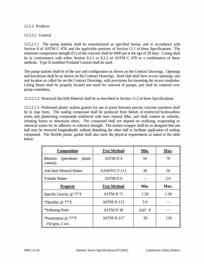
SPEC-12-34 Sanitary Sewer Specifications (07/2002) Lakehaven Utility District
12.5.2 Products 12.5.2.1 General 12.5.2.1.1 The pump stations shall be manufactured as specified herein, and in accordance with Section 8 of ASTM C 478, and the applicable portions of Section 12.1 of these Specifications. The minimum compressive strength (f'c) of the concrete shall be 6000 psi at the age of 28 days. Curing shall be in conformance with either Section 8.2.1 or 8.2.2 of ASTM C 478 or a combination of these methods. Type II modified Portland Cement shall be used. The pump stations shall be of the size and configuration as shown on the Contract Drawings. Openings and knockouts shall be as shown on the Contract Drawings. Roof slab shall have access openings, size and location as called for on the Contract Drawings, with provisions for mounting the access manholes. Lifting Beam shall be properly located and sized for removal of pumps, and shall be centered over pump centerlines. 12.5.2.1.2 Structural Backfill Material shall be as described in Section 11.2 of these Specifications. 12.5.2.1.3 Preformed plastic sealant gaskets for use in joints between precast concrete members shall be in rope form. The sealing compound shall be produced from blends of reinforced hydrocarbon resins and plasticizing compounds reinforced with inert mineral filler, and shall contain no solvents, irritating fumes or obnoxious odors. The compound shall not depend on oxidizing, evaporating or chemical action for its adhesive or cohesive strength. The sealant wrapper shall be so designed that one half may be removed longitudinally without disturbing the other half to facilitate application of sealing compound. The flexible plastic gasket shall also meet the physical requirements as stated in the table below:
Composition
Test Method
Min.
Max.
Bitumen (petroleum plastic content)
ASTM D 4
50
70
Ash-Inert Mineral Matter
AASHTO T-111
30
50
Volatile Matter
ASTM D 6
--
2.0
Property
Test Method
Min.
Max.
Specific Gravity @ 77°F
ASTM D 71
1.20
1.30
*Ductility @ 77°F
ASTM D 113
5.0
--
*Softening Point
ASTM D 36
320? F
--
*Penetration @ 77°F 150 gms, 5 sec.
ASTM D 217
50
130
Lakehaven Utility District Sanitary Sewer Specifications (07/2002) SPEC-12-35
*NOTE: Due to the nature of the material, each sample to be tested must be manually kneaded, in lieu of heating and pouring into various molds suggested by ASTM Standards, to reduce the void content and improve testing accuracy and reproducibility. Primer for concrete surfaces shall be compatible with plastic sealant gaskets and shall be manufactured by the same company that fabricates gasket material. 12.5.2.1.4 Ladders shall be furnished and installed in accordance with Section 12.6.3.9 of these Specifications. 12.5.2.1.5 Waterproofing of the pump station shall be as specified in Section 17.1, WATERPROOFING WITH SPECIAL COATINGS. 12.5.2.1.6 The top and bottom slabs of the pump station shall be given a Class 1 Slab Finish for Concrete Slabs as described in Section 12.3 of these Specifications. 12.5.2.1.7 The interior and exterior faces of the pump station walls shall be given a Class 2 Surface Finish for Vertical and Horizontal Formed Surfaces Section 12.3 of these Specifications. 12.5.3 Execution 12.5.3.1 General 12.5.3.1.1 The pump stations shall be as noted on the Contract Drawings. All joints shall be made watertight. 12.5.3.1.2 The pump stations shall be accurately set to line and grade on a previously prepared compacted foundation material having a thickness not less than one (1) foot. Walls shall be plumb and the base slab shall be level. See Section 3.3 and Section 3.5.7 of the Lakehaven Utility District Sanitary Sewer Specification for foundation material. 12.5.3.1.3 Backfill around the pump stations shall be Structural Fill material. The backfill material shall be compacted to 95 percent of relative compaction to the final finish grade over an area defined as being within a distance of four (4) feet from the exterior walls of the pump stations. 12.5.3.1.4 The Contractor is responsible for accurately locating and placing the manhole frame and cover on the access manholes to within 1/8-inch vertical elevation in paved areas and to 1/2-inch in other areas. The Contractor shall coordinate the activities of all trades so that this tolerance is achieved. 12.5.3.2 Setting Pipe Spools Set all spools not cast in place in the structure using epoxy grout specified in this section.
SPEC-12-36 Sanitary Sewer Specifications (07/2002) Lakehaven Utility District
12.6 PRECAST REINFORCED CONCRETE PUMP STATION 12.6.1 General 12.6.1.1 This section includes furnishing and installing all materials (Standard manhole structures) required to construct submersible pump station wet wells and valve vaults as identified on the Contract Drawings. 12.6.2 Material List The Contractor shall submit to the Engineer a list of materials in accordance with the appropriate section of the Conditions of the Contract. The list shall include all items of material for standard precast components, jointing material, fittings and accessories, the name of the manufacturer of each item, the specific contract reference, and the Standard Specification to which each item is manufactured. The material list shall be approved by the Engineer before any manholes or cleanouts are installed. 12.6.3 Materials 12.6.3.1 Pump Station components shall be constructed either entirely of precast concrete sections or of precast concrete section on a cast-in-place base. 12.6.3.2 Steel lifting loops or hooks for precast components shall be removed to a depth of one (1) inch below the surface of the concrete and the concrete shall be patched. Lift holes shall be solidly filled with dry pack grout. 12.6.3.3 Precast components shall conform to the requirements of ASTM Designation C-478. All Portland Cement used in the manufacture of the precast sections shall conform to the requirement of ASTM Designation C-150 and shall be Type II or Type V. 12.6.3.4 Precast base sections shall conform to the requirements for precast riser sections except that a reinforced base slab shall be cast monolithically with the walls or otherwise constructed to achieve a watertight structure. Base slab thickness shall be six (6) inches, minimum. Base slabs shall be reinforced as shown on the Contract Drawings. The walls of the base section shall be reinforced in accordance with ASTM C-478. 12.6.3.5 Pipe to Wet Well (Manhole) connector: The "A-LOK" Pipe to Manhole Connector shall be utilized for all pipe connections in the locations shown on the Contract Drawings. It shall be integrally cast in place in the concrete wet well (manhole) wall to the correct line, grade and size as indicated on the Contract Drawings. It shall meet or exceed all material and performance requirements of ASTM Standard C-923: Resilient Connectors Between Reinforced Concrete Manhole Structures and Pipes. It shall produce a positive watertight connection. A-Lok pipe connectors or an approved equal shall be used for all pipe types eight-inch and larger. 12.6.3.6 Standard precast riser sections shall consist of circular sections in standard nominal inside diameters as designated on the Contract Drawings. Reinforcement shall be in accordance with ASTM C-478. Minimum height of a riser section shall be one (1) foot. Heights of a riser and based sections shall be arranged so no pipes pass through the joining surfaces. Openings for pipe shall be circular, tapered toward the inside of the section, and shall be of the minimum size possible to accommodate the
Lakehaven Utility District Sanitary Sewer Specifications (07/2002) SPEC-12-37
pipe to be inserted and to effectively seal the joint. 12.6.3.7 The roof structure shall be made by means of a flat concrete slab with adequate opening for proper installation of the access doors, See Section 12.8 of these Specifications. The slab shall be a minimum of 12 inches thick and shall conform to the outer dimensions of the section on which it will be placed. The access door opening shall be as located on the Contract Drawings or as directed by the Engineer. 12.6.3.8 Standard precast components shall be installed with synthetic rubber gaskets; where high ground water is encountered or at the direction of the Engineer, a second sealant-type gasket as described in Section 12.6.3.10 of these Specifications shall be required. 12.6.3.9 A.fiberglass ladder shall be installed in base sections and riser sections so that the completed pump station will have a continuous vertical ladder with equally spaced rungs as shown on the Contract Drawings. 12.6.3.9.1 Fiberglass access ladder shall have one-inch (1") round fluted rungs with anti-slip ridges and shall be field-measured before fabrication. The access ladder shall be a manufactured ladder; extended to the floor of the vault, with the last ladder rung a minimum of twelve inches (12") and a maximum of eighteen inches (18") above the floor. The maximum vertical distance between rungs shall be twelve inches (12"), measured center to center. 12.6.3.9.1.1 The ladders shall meet or exceed all OSHA safety requirements for load and safety requirements. 12.6.3.9.1.2 The manufacturer shall guarantee the ladders for a period of five (5) years. 12.6.3.9.1.3 The rungs shall be round, with a non-skid surface. The rungs shall be eighteen inches (18") wide, and a minimum diameter of two inches (2"). 12.6.3.9.1.4 Ladders shall be installed level, plumb, and per manufacturer's instructions. Anchor bolts used shall be a minimum 1/2-inch diameter stainless steel, type SS312. 12.6.3.10 Joint Sealant 12.6.3.10.1 The standard pump station shall have a manhole joint sealing system utilizing flexible sewage-resistant synthetic rubber gaskets conforming to the requirements of ASTM Designation C-443. Gasket joint details shall be subject to approval by the Engineer. 12.6.3.10.2 A preformed joint sealant shall be used. This sealant shall be in rope form conforming to the requirements of Federal Specifications SS-S-210 and shall be "Kent-seal" as manufactured by Hamilton Kent Manufacturing Company, "Ram-nek" as manufactured by K.T. Snyder Company, or approved equal.
SPEC-12-38 Sanitary Sewer Specifications (07/2002) Lakehaven Utility District
12.6.4 Installation 12.6.4.1 Pump Station installation shall be as detailed on the Contract Drawings. Precast sections with damaged joint surfaces or with cracks or damage that would permit infiltration shall not be installed. 12.6.4.2 Precast base sections shall be set on a prepared pea gravel base. Pea gravel shall be as specified in Section 3.4.5 of the Lakehaven Utility District Sanitary Sewer Specifications. Before the precast base is set, the pea gravel shall be carefully leveled to provide full bearing for the entire base slab. Leveling the base section by wedging base sections shall be set level and perpendicular. 12.6.4.3 Precast riser sections and top slabs shall be set using the specified joint sealant or gasket. Priming and preparation of surfaces and installation of jointing material shall be in strict accordance with the manufacturer's instructions. 12.6.4.4 The access door frames shall be set carefully to the established surface grade in a full bed of cement grout. The access door elevation shall be set in accordance with the Contract Drawings. 12.7 CONFINED SPACE RESCUE AND RETRIEVAL SYSTEM 12.7.1 General 12.7.1.1 Description. This section covers the retrieval system utilized for entering wet well and valve vault locations. 12.7.1.1.1 Scope: Provide necessary equipment, labor as required to install a functional system. 12.7.1.2 Submittals. Submit to the Engineer for approval a list of items to be furnished, even though these items conform to the exact description stated in this section or shown on the Contract Drawings. 12.7.2 Products 12.7.2.1 General. Provide only new materials made from first quality ingredients and guaranteed to perform the required service. 12.7.2.2 Provide a Uni-Hoist Model US101/US101SS anti-fall device bracket (National Safety Catalog No. 654-1-316), mounted above ground on the concrete surface of the wet well in accordance with the manufacturer's specifications.
Lakehaven Utility District Sanitary Sewer Specifications (07/2002) SPEC-12-39
12.8 ACCESS DOORS 12.8.1 General 12.8.1.1 Description. This section describes materials and installation of the access doors for each wet well and valve vault entrance. The Contract drawings shall identify the number of doors that will be used for each structure. 12.8.1.2 Guarantee. The manufacturer shall guarantee the access doors against defects for a period of five (5) years. 12.8.1.3 Submittals. Submit catalog cuts or detail drawings and designs of all items specified. 12.8.2 Products 12.8.2.1 Access Doors. Provide access hatch assembly (doors) manufactured by the Bilco Company, New Haven, Connecticut or L.W. Hatch Company, Bothell, Washington as specified on the Contract Drawings for the wet well and valve vault. 12.8.2.1.1 Channel Frame. The channel frame shall be 1/4-inch aluminum with an anchor flange around the perimeter. 12.8.2.1.2 Door Leaf. The door leaf shall be 1/4-inch aluminum diamond pattern plate reinforced to withstand H20 wheel loading. For all double and triple leaf door combinations, the ladder side door shall open first. 12.8.2.1.3 Drain Coupling. Provide a 1 X 1-1/2 inch aluminum drainage half-coupling located as shown on the Contract Drawings. 12.8.2.1.4 Equipment. Doors shall be equipped with: 1. 316 Stainless Steel:
a. Lifting mechanism housing.
b. Automatic hold-open arm and cover release.
c. Pins.
d. Slam lock and spoon handle.
e. Release handle.
2. Corrosion resistant stainless steel lifting spring.
3. Neoprene gasket.
4. Red vinyl grip on the release handle.
12.8.2.1.5 Frame Finish. The exterior of the frame that will be in contact with concrete shall have a mill finish with a minimum ten (10) mil dry film thickness holiday-free coating of Koppers Bitumastic 50. The coated surface shall be covered with ten (10) mil thick pressure-sensitive tape to protect it from
SPEC-12-40 Sanitary Sewer Specifications (07/2002) Lakehaven Utility District
damage during installation. 12.8.2.1.6 Hardware. Use only 316 stainless steel hardware. 12.8.2.1.7 Mill Finish. Provide mill finish on all aluminum surfaces. 12.8.2.1.8 Padlock Hasp. Provide an aluminum recessed padlock hasp with an aluminum cover. 12.8.2.1.9 Warning Signs. Furnish a warning sign on the underside of the access door adjacent to hold-open latch, reading:
DANGER MAKE SURE “HOLD-OPEN LATCH” IS ENGAGED BEFORE USING.
CONFINED ENTRY REQUIRED - APPROVED SAFETY DEVICE MUST BE UTILIZED.
12.8.3 Installation. Install access doors in accordance with the manufacturer's instructions. For all double and triple leaf door combinations, the ladder side door shall open first.
Lakehaven Utility District Sanitary Sewer Specifications (07/2002) SPEC-13-1
SECTION 13
MECHANICAL EQUIPMENT 13.1 GENERAL EQUIPMENT AND MECHANICAL REQUIREMENTS 13.1.1 General 13.1.1.1 Description. 13.1.1.1.1 Scope: The provisions of this section are the general requirements for all of the Equipment and Mechanical work in the scope of a submersible pump station project and wherever specifically required in these Specifications. 13.1.1.1.2 The Contractor shall direct the attention of all subcontractors and suppliers of equipment and related appurtenances for the work to the applicable provisions in the Contract Documents wherever they may occur. 13.1.1.2 Standards For The Work 13.1.1.2.1 Complete Systems: Pipe, fittings, wiring and supports shall be provided to produce complete, operable systems with all elements properly interconnected as shown in schematic diagrams or to provide specified operations. If a specific dimensioned location is not shown for interconnections or smaller system elements, the Contractor shall select appropriate locations and show them on Shop Drawing submittals for review. 13.1.1.2.2 Equipment and material shall be new and without imperfections and shall be erected in a neat and workmanlike manner; aligned, leveled, cleaned and adjusted for satisfactory operation; installed in accordance with the recommendations of the manufacturers and the best standard practices for this type of work so that connecting and disconnecting of piping and accessories can be readily made and so that all parts are easily accessible for inspection, operation, maintenance and repair. Oil and lubrication fittings shall be located clear of and away from guards, base, and equipment and within reach from the operating floor. In order to meet these requirements with equipment as furnished, minor deviation from the Contract Drawings may be made as approved by the Engineer. 13.1.1.3 Manufacturer's Instructions. The recommendations and instructions of the manufacturers of products used in the work are hereby made part of these Specifications, except as they may be superseded by other requirements of these Specifications. 13.1.1.4 Submittals 13.1.1.4.1 Shop Drawings: Shop Drawings shall be submitted to the Engineer and approved prior to fabrication, construction or delivery to the project site in accordance with these Specifications, showing
SPEC-13-2 Sanitary Sewer Specifications (07/2002) Lakehaven Utility District
sizes and arrangement of equipment, foundations and anchor bolts required, performance characteristics, fan curves and pump curves, control diagrams, wiring diagrams, motor data sheets, methods of assembly, pipe hanging details, ductwork layouts and connections to other work. Contract Drawings shall be dated and signed as certified for use in construction of this project. The arrangement of mechanical equipment and appurtenant piping shown on the Contract Drawings may be varied as necessary to fit the approved certified manufacturer's installation Drawings. However, the manufacturers' drawings shall not deviate from the Contract Drawings and Specifications as to location, size, type and design of equipment. The following minimum requirements shall accompany all equipment submissions: 1. Overall dimensions.
2. Mounting arrangement and dimensions.
3. Description of materials.
4. Connection sizes and orientation.
5. Capacity and location of lifting eyes.
6. Motor arrangement showing location of electrical connections.
7. Rating data - Mechanical and Electrical as applicable.
8. Detail electrical wiring diagrams, showing component designation and rating.
9. Seismic calculations.
10. List of special tools and/or spare parts required and to be furnished, if any.
Each piece of equipment, for which certified witnessed or non witnessed performance tests are required, shall be accompanied by a completed form which will contain at least the following information: 1. Owner's name and location of project.
2. Contractor's name and subcontractor if applicable.
3. Name of item being submitted.
4. Specification references by section, paragraph and page.
5. Data on item (manufacturer, general descriptive data, dimensions, size of connections, speeds, performance curves, and serial number).
6. Motor data, type, voltage, frequency, phase, full load amperes, starting method, frame size, enclosure insulation type (NEMA Code letter), dimensions, service factor, serial number.
7. Date and signature of person certifying the performance.
All motor connections shall be located as shown on the Contract Drawings and the most current

Lakehaven Utility District Sanitary Sewer Specifications (07/2002) SPEC-13-3
Lakehaven Utility District Standard Plans.
SPEC-13-4 Sanitary Sewer Specifications (07/2002) Lakehaven Utility District
13.1.1.4.2 Operation and Maintenance Instruction Manuals: Prepare and submit four (4) sets each of instructional manuals in D-ring binders and VHS videotapes covering all equipment and machinery specified. See Section 13.1.3.7 of these Specifications. All Operation and Maintenance Manuals shall also be provided in Microsoft Word 97 electronic format. All associated drawings shall be provided in Autocad 2000 electronic format. 13.1.1.4.3 Manufacturers' Affidavits: Equipment manufacturers, or their authorized representatives, shall each submit a notarized written report with respect to his/her equipment certifying that (1) the equipment has been properly installed and lubricated, (2) the equipment is in accurate alignment, (3) the manufacturer was present when the equipment was placed in operation, (4) the manufacturer has checked, inspected, and adjusted the equipment as necessary, (5) the equipment is free from any undue stress imposed by connecting piping or anchor bolts, (6) the equipment is not imposing any undue stress on any connecting members, (7) the equipment has been operated satisfactorily under full load conditions, (8) the manufacturer has inspected his/her equipment during the operational demonstrations and system validation tests to the extent specified, and (9) the equipment is fully covered under the terms of the guarantee. Equipment for which Affidavits shall be provided shall include the following: 1. Emergency Generator
2. Pumps
3. Control Panels
13.1.1.5 Responsibility And Care Of Equipment 13.1.1.5.1 The Contractor shall be responsible for the equipment included in the Contract until it has been finally inspected, tested and accepted in accordance with the requirements of these Specifications. 13.1.1.5.2 The Contractor shall make his/her own provisions for properly storing and protecting all material and equipment against theft, injury or damage from any and all causes. Damaged material and equipment shall not be used in the work. 13.1.1.6 Factory Tests 13.1.1.6.1 Factory tests shall be performed for each piece of equipment where specifically called for in the section specifying that equipment. Note that factory tests are inherent in many reference standards. The requirement for a factory test in a referenced standard shall make that requirement a part of these Specifications. Conduct factory tests at the same speeds at which the equipment will operate in the field, except as noted.
Lakehaven Utility District Sanitary Sewer Specifications (07/2002) SPEC-13-5
13.1.1.6.2 Where specifically noted, performance tests may be witnessed by the Engineer or his/her representative. The Contractor shall inform the Engineer in sufficient time to allow arrangements to be made for witness of such tests. When non-witnessed tests are performed, certified results shall be supplied by the Contractor to the Engineer. 13.1.1.6.3 Factory testing of pumps shall be done in accordance with the requirements and standards of the Hydraulic Institute. Tests of other equipment shall conform to the requirements set forth in these Specifications. 13.1.2 Products 13.1.2.1 Design. All equipment shall be designed for the service intended, of rugged construction, of ample strength for all stresses which may occur during fabrication, transportation, erection and during continuous or intermittent operation, shall be adequately stayed, braced and anchored, and shall be installed in a neat and workmanlike manner. Appearance and safety, as well as utility, shall be given consideration in the design of details. Materials of construction will be cathodically compatible. 13.1.2.2. Materials And Standard Requirements 13.1.2.2.1 Materials: Design, fabricate and assemble equipment and systems with new materials and in accordance with acceptable modern engineering and shop practices. Manufacture individual parts to standard sizes and gauges so repair parts can be installed in the field. Make like parts of duplicate units interchangeable. Do not place equipment in service at any time prior to delivery except as required for factory or shop tests. 13.1.2.2.2 Uniformity: Unless otherwise specified, equipment or material of the same type or classification used for the same purpose shall be the product of the same manufacturer and shall be the same model. 13.1.2.2.3 Standard Requirements: Provide equipment and materials suitable for service conditions and meeting standard requirements of ANSI, ASME, AWWA, ASTM, NEMB, UBC, UPC, UL and OSHA. 13.1.2.3 Lubrication. Provide lubricants of types recommended by equipment manufacturers, in quantities sufficient for consumption prior to completion, testing and final acceptance. Provide equipment lubrication systems that require attention no more often than weekly during continuous operation, do not require attention during start-up or shutdown, and do not waste lubricants. 13.1.2.4 Equipment Bases And Bedplates. Mount equipment assembles on a single heavy cast iron or welded steel bedplate on a grout or concrete base unless otherwise shown or specified. Provide bases and bedplates with machined support pads, tapered dowels for alignment or mating of adjacent items, adequate openings to facilitate grouting, and openings for electrical conduits. Corners shall be rounded or chamfered and ground smooth. Continuously weld seams and contact edges between steel plates
SPEC-13-6 Sanitary Sewer Specifications (07/2002) Lakehaven Utility District
and shapes, and grind welds smooth. Do not support machinery or piping on bedplates other than that which is factory installed. Provide jacking screws in equipment bases and bedplates to aid in leveling prior to grouting. 13.1.2.5 Anchors And Fasteners 13.1.2.5.1 Each equipment manufacturer shall furnish the required anchor bolts, nuts and washers of adequate design for securing bases and bedplates to concrete bases. Provide anchor bolts of length to allow for 1-1/2 inch of grout under baseplates and adequate anchorage into structural concrete unless otherwise shown or specified. 13.1.2.5.2 Anchor and assembly bolts and nuts shall be of ample size and strength for the purpose intended. All bolts shall be standard machine bolts, with cold pressed hexagon nuts. Unless otherwise specified or noted on the Contract Drawings, materials shall be as follows: Bolts in below ground locations or submerged and embedded in concrete or buried in earth shall be type 316 stainless steel. Bolts for supports or equipment in above ground locations shall be stainless steel, with oversize nuts. Provide suitable degauling compounds for bronze and stainless steel threaded components. Any space wholly or partially underground, or having a wall or ceiling forming part of a water channel, is classified as a wet location. 13.1.2.5.3 Other bolting materials shall be used where specifically called for in these Specifications or on the Contract Drawings. 13.1.2.5.4 Anchor all non-motor-driven equipment with cast-in-place anchor bolts or drilled-in anchors set with epoxy adhesive except that, where specifically allowed by note on the Contract Drawing, expansion type anchors may be used. 13.1.2.6 Safety Guards 13.1.2.6.1 Cover belt or chain drives, fan blades, couplings, exposed shafts and other moving or rotating parts on all sides with safety guards conforming to all Federal, State, and local codes and regulations pertaining; conform to the most restrictive requirement. Design guards for easy installation and removal, complete with necessary supports, accessories, and fasteners, all hot-dip galvanized. Design guards in outdoor locations to prevent entrance of rain and dripping water. Provide tachometer test opening in line with ends of shafts. Typically guards shall be expanded metal on a structural steel frame except that outdoor guards may be of solid material. Provide spring loaded hinged doors with latch for service and lubrication access. 13.1.2.6.2 All pipes, manifolds, heaters, and other surfaces which have a surface temperature sufficient to burn human tissue, shall be covered with a thermal insulating material or otherwise guarded against contact. 13.1.2.6.3 Guards shall comply with the requirements of these Specifications, WISHA Standards, and

Lakehaven Utility District Sanitary Sewer Specifications (07/2002) SPEC-13-7
"The Principles and Techniques of Mechanical Guarding" (OSHA 2057, 1973), whichever is more stringent.
SPEC-13-8 Sanitary Sewer Specifications (07/2002) Lakehaven Utility District
13.1.2.7 Lifting Eyes. All equipment weighting over 100 pounds shall be supplied with lifting eyes. Parts of equipment assemblies which are normally serviced separately, such as motors, shall have lifting eyes of their own. 13.1.2.8 Codes For Pressure Vessels. All pressure vessels shall be designed, constructed and tested in compliance with applicable codes of the ASME. Pressure vessels shall bear the nameplate of the ASME Code and shall be stamped with the Code and symbol by an ASME inspector. A data sheet shall be filled out on ASME Form U-1 by the manufacturer and shall be signed by the manufacturer and the inspector for each pressure vessel marked with the Code U symbol. All completed data sheets shall be turned over to the Engineer, including X-ray inspections. 13.1.2.9 Nameplates 13.1.2.9.1 Manufacturer's Nameplate: Each piece of equipment and its driver shall be furnished with a corrosion-resistant metal nameplate fastened to the item in an accessible position. This nameplate shall contain the manufacturer's name, equipment rating, capacity, size, model, serial number and speed. Data for motors shall be NEMA standard. All information written or printed shall be in English. Each item of equipment shall bear a different serial number. Measurement units shall be given for ratings and capacity. 13.1.2.9.2 Nameplates for tanks and pressure vessels shall give working pressure, test pressure, vessel plate thickness and ASME Code data. 13.1.2.9.3 Direction of Rotation: Each piece of rotating equipment shall have a direction of rotation arrow. 13.1.2.9.4 Functional Identification: Each piece of equipment shall be labeled using a plastic laminate label with the functional name and number of the equipment shown on the Contract Drawings. Name and number shall correspond to those used on Motor Control Centers and Panels. 13.1.2.9.5 Labels shall be fastened to the equipment, its base or other acceptable location. The letters shall be at least 1/2-inch high with the border trim on all sides not less than 1/4-inch. Color shall be green background with white letters. Fasteners shall be brass or stainless steel screwed into inserts, anchor shields or tapped holes in equipment or base. 13.1.2.9.6 Meter and Gauge Readout: Units of measure shall be shown on the indicating and totalizing dials of all meters, gauges and other measuring devices. 13.1.2.10 Protection Against Electrolysis. Where dissimilar metals are used in conjunction with each other, suitable insulation shall be provided between adjacent surfaces so as to eliminate direct contact and any resultant electrolysis. The insulation shall be bituminous impregnated felt,
Lakehaven Utility District Sanitary Sewer Specifications (07/2002) SPEC-13-9
heavy bituminous coatings, non-metallic separators or washers or other approved materials. Connections of dissimilar piping materials shall utilize dielectric unions, flanges, couplings or bushings. 13.1.2.11 Contacts. For interlock or failure indicating contacts specified to be supplied as part of equipment, provide SPDT switches rated for 120 VAC, 60 Hz at five (5) amperes resistive or three (3) amperes inductive loading, and terminated at screw-type barrier strips in a NEMA 4 enclosure, unless otherwise shown on the Contract Drawings or specified in the Contract Specifications. 13.1.2.12 Painting 13.1.2.12.1 Conform to applicable requirements of Section 17.1 WATER-PROOFING WITH SPECIAL COATINGS and Section 17.2, PROTECTIVE COATINGS, of these Specifications and the following requirements unless modified or superseded under other sections. 13.1.2.12.2 Factory Painting: On pumps, motors, drives, starters, control panels and other similar self-contained or enclosed components, apply a factory primer and high quality oil-resistant baked industrial enamel finish. Paint or otherwise protect surfaces that are inaccessible after assembly by a method which provides protection for the life of the equipment. 13.1.2.12.3 Shop Priming: Apply one (1) or more shop coats of metal primer on surfaces to be finish painted at the site, of sufficient thickness to protect surfaces until finished. Use primers specified for the required paint systems in Section 17.1 WATERPROOFING WITH SPECIAL COATINGS and Section 17.2 PROTECTIVE COATINGS of these Specifications. 13.1.2.13 Noise And Vibration. Mechanical and electrical equipment shall not create sound levels that are in excess of that permitted by WISHA for eight (8) hours per day worker exposure unless otherwise noted for the specific piece of equipment involved. If the equipment in its designated environment cannot meet the required sound level, sound attenuating enclosures shall be provided. Sound attenuating enclosures shall have necessary ventilation to prevent equipment overheating and shall be constructed to allow easy removal for maintenance purposes. Devices necessary for day-to-day operation shall pierce the enclosure or otherwise be accessible without need to remove the enclosure. 13.1.3 Execution 13.1.3.1 Inspection. Inspect each item of equipment for damage, defects, completeness, and correct operation before installing. Inspect previously installed related work and verify that it is ready for new equipment installation. 13.1.3.2 Preparation. Prior to installing equipment, ensure that the areas are clean and that concrete or masonry operations are completed. Maintain the areas in a broom-clean condition
SPEC-13-10 Sanitary Sewer Specifications (07/2002) Lakehaven Utility District
during installation operations. Clean, condition, and service equipment in accordance with the approved Operation and Maintenance Instruction Manuals and specific requirements included in applicable sections of these Specifications. 13.1.3.3 Manufacturers' Supervision And Affidavit. Each equipment manufacturer shall furnish the services of an authorized representative especially trained and experienced in the installation of his/her equipment to (1) supervise the equipment installation in accordance with the approved Operation and Maintenance Instruction Manual, (2) be present when the equipment is first put into operation, (3) inspect, check, adjust as necessary, and approve the installation, (4) repeat the inspection, check and adjust until all trouble or defects are corrected and the equipment installation and operation are acceptable, (5) witness and supervise operational demonstrations and system validation tests to the extent specified, and (6) prepare and submit the specified Manufacturer's Affidavit. Include all costs for representative's service in the Contract Price. 13.1.3.4 Installation 13.1.3.4.1 Structural Fabrications: Structural fabrications shall conform to the AISC Code and Specification referenced in Article "Structural Steel Fabrications," and conform to the Contract Drawings and Specifications. 13.1.3.4.2 Equipment: Equipment shall conform to the approved Operation and Maintenance Instruction Manuals. Employ skilled craftsmen experienced in installation of the types of equipment specified. Use specialized tools and equipment, such as precision machinist levels, dial indicators, gauges, and micrometers, as applicable. Produce acceptable installations free of vibration or other defects. 13.1.3.4.3 Anchor Bolts: Deliver bolts with templates or setting drawings and verify that bolts are correctly located before structural concrete is placed. 13.1.3.4.4 Base and Bedplate Grouting: Do not place grout until initial fitting and alignment of connected piping is completed. Level and align equipment on the concrete foundations, then entirely fill the space under base or bedplates with grout. Bevel exposed grout at 45 degree angle, except around exposed grout at horizontal surfaces for drainage. Trowel or point exposed grout to a smooth, dense finish and damp cure with burlap for three (3) days. When grout is fully hardened, removed jacking screws and tighten nuts on anchor bolts. Check the installation for alignment and level, and perform approved corrective work as required to conform to the tolerances given in the applicable Operation and Maintenance Instruction Manual. 13.1.3.4.5 The Contractor shall make an allowance of at least 1-1/2 inches for grout under the equipment bases, whether or not shown on the Contract Drawings. Shims used to level and adjust the bases shall be steel. Shims may be left embedded in the grout, in which case they shall be installed neatly and so as to be as inconspicuous as possible in the completed work. Unless otherwise approved, all grout shall be an approved non-shrink, non-metallic grout as identified in Section
Lakehaven Utility District Sanitary Sewer Specifications (07/2002) SPEC-13-11
12.1.2.15 of these Specifications. 13.1.3.4.6 Where practicable, the grout shall be placed through the grout holes in the equipment base and worked outward and under the edges of the base and across the rough top of the concrete foundation to a peripheral form so constructed as to provide a suitable chamfer around the top edge of the finished foundation. 13.1.3.5 Equipment Start-Up And Adjustment. The Contractor, at his/her own expense, shall arrange for an authorized factory-trained representative of the company or companies supplying the various items of equipment to check the installation, adjust and test the equipment furnished before the acceptance of the work by the District. Said representative shall be experienced and knowledgeable of the equipment being tested. Furthermore, he/she shall assist and instruct the District's operating staff in adjusting and operating the equipment during the initial start-up period. 13.1.3.5.1 Initial lubrication shall be given all equipment by the Contractor. 13.1.3.5.2 All equipment shall be tested and demonstrated to the District's representative that proper operation and capacity have been fully complied with. For pumps, this shall include measurement of discharge pressure at the valve box and measurement of pumping rate by volumetric means, or through a suitably calibrated meter for two (2) points on the performance curve. For two-speed pumps, such tests shall be conducted at both speeds. Any test equipment or measuring devices required which are not part of the permanent installation shall be furnished by the Contractor. 13.1.3.5.3 In addition, the entire facilities shall be demonstrated to be in full operating order prior to the acceptance of the work. Should any equipment or part thereof fail to operate as intended, it shall be immediately removed and replaced, all at the Contractor's expense. The Contractor shall pay for all tests involved in this section. 13.1.3.6 Sound Level Testing. Measure the sound level developed by all mechanical and electrical equipment provided under the Contract Documents. Perform testing in all rooms and spaces containing such equipment during the final operation test program with all equipment operating. Use OSHA approved instrument and record the highest sound level developed when measured according to OSHA standards in each room and space. Deliver a certified copy of records to the Engineer. 13.1.3.7 Operation And Maintenance Instruction Manuals 13.1.3.7.1 The subject matter to be included in Operation and Maintenance Instruction Manuals (O&M Manuals) shall cover, but not be limited to, the following: 1. Start-Up.
2. Normal Operation.
3. Alternative Specified Operating Modes.
SPEC-13-12 Sanitary Sewer Specifications (07/2002) Lakehaven Utility District
4. Emergency Operation.
5. Normal Shut Down.
6. Long Term Shut Down (Mothballing).
7. Operator Safety.
8. Lubrication.
9. Maintenance.
10. Parts Identification and a complete parts breakdown for all equipment. 13.1.3.7.2 Four (4) copies of complete O&M Manuals shall be provided when the pump station is 60 to 70 percent complete. All O&M Manuals shall also be provided in Microsoft Word 97 electronic format for the District's use. All associated drawings shall be provided in Autocad 2000 electronic format. 13.1.3.7.3 The O&M Manuals shall be bound in D-ring binders. 13.1.3.7.4 Summary sheets shall be provided for each equipment unit provided. The summary sheets shall include the following as a minimum: 1. Equipment Item.
2. Manufacturer.
3. Serial Number.
4. Nameplate Data.
5. Manufacturer's local Representative, address and telephone number.
6. Maintenance Schedule, Broken down into:
a. Daily d. Quarterly
b. Weekly e. Semi-Annually
c. Monthly f. Annually
13.1.3.7.5 The O&M Manuals shall include a list of spare parts provided. 13.1.3.7.6 The O&M Manuals shall include all equipment provided on the Contract. The O&M Manuals shall be indexed and include a Table of Contents. 13.1.3.7.7 The O&M Manuals shall include the factory documentation for all guarantees and warrantees. 13.1.3.8 Spare And Loose Parts
Lakehaven Utility District Sanitary Sewer Specifications (07/2002) SPEC-13-13
13.1.3.8.1 Spare and Loose Parts Supplied: Provide an inventory of spare and loose parts required to be supplied under the project. Turn over inventory and parts to the District. The District's written acknowledgment of receipt is required for project completion. Loose parts are defined as items such as special tools, keys, safety equipment, and portable equipment. The following spare parts shall be provided as a minimum, as listed on the Contract Drawings: • 1 ea. Slip Flange Gasket Set • 1 ea. Air Filter for Generator • 1 ea. Fuel Filter for Generator • 1 ea. Oil Filter for Generator • 1 ea. Pump Impeller (trimmed and balanced) • 1 ea. Pump Wear Ring Set • 1 ea. Pump Impeller Bolt and Washer Set • 1 ea. Mechanical Seal Assembly Set (complete) • 1 ea. Pump Gasket and O-ring Set (complete) • 1 ea. Check Valve Spring • 5 gal. Pump Motor Oil 13.1.3.8.2 Recommended Spare Parts: Furnish a complete list of recommended spare parts and supplies, for each piece of equipment furnished with current prices and a local source of supply, if possible. 13.1.3.9 Instruction Of District's Personnel 13.1.3.9.1 Conduct an instruction program for operations personnel designated by the District. Furnish the services of qualified instructors from the various equipment manufacturers. Include instruction covering basic system operation theory, routine maintenance and repair, and "hands on" operation of equipment.
SCHEDULE
Instruction Period
System
Total for the Job
Emergency Generator
1 day
Pumps
1/2 day
Pump Control Panel
1/2 day
Generator Transfer Switch
1/2 day
SPEC-13-14 Sanitary Sewer Specifications (07/2002) Lakehaven Utility District
13.1.3.9.2 Provide the instruction program at the District's convenience before contract closeout. Also provide to the District any audio-visual training materials the manufacturer utilizes (i.e. video cassettes, slides, films, etc.). Cost of instruction and audio-visual training materials shall be included in the contract bid price.
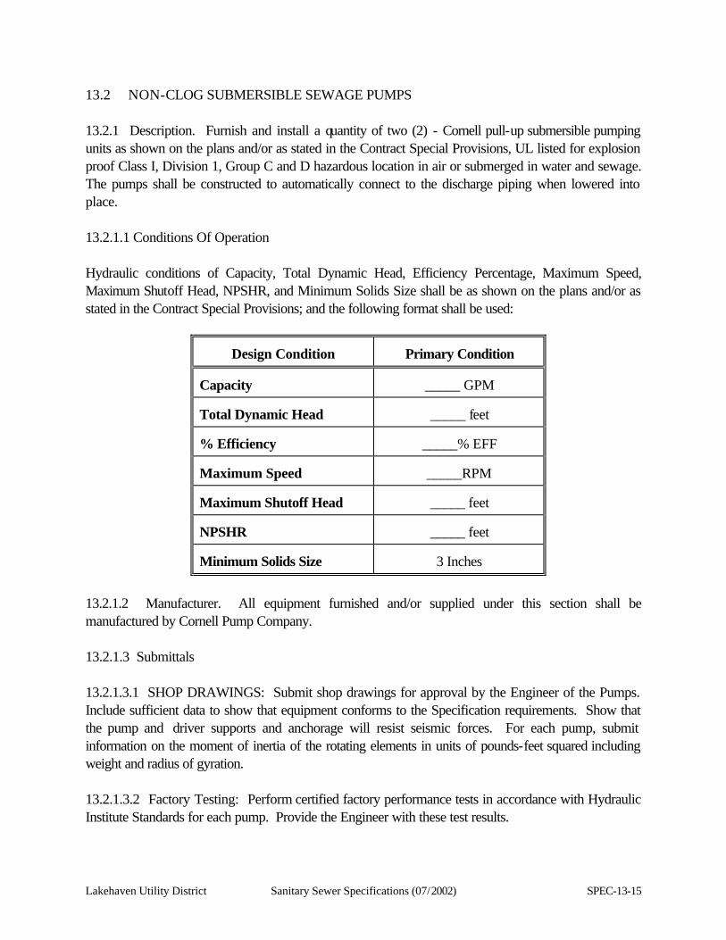
Lakehaven Utility District Sanitary Sewer Specifications (07/2002) SPEC-13-15
13.2 NON-CLOG SUBMERSIBLE SEWAGE PUMPS 13.2.1 Description. Furnish and install a quantity of two (2) - Cornell pull-up submersible pumping units as shown on the plans and/or as stated in the Contract Special Provisions, UL listed for explosion proof Class I, Division 1, Group C and D hazardous location in air or submerged in water and sewage. The pumps shall be constructed to automatically connect to the discharge piping when lowered into place. 13.2.1.1 Conditions Of Operation Hydraulic conditions of Capacity, Total Dynamic Head, Efficiency Percentage, Maximum Speed, Maximum Shutoff Head, NPSHR, and Minimum Solids Size shall be as shown on the plans and/or as stated in the Contract Special Provisions; and the following format shall be used:
Design Condition
Primary Condition
Capacity
_____ GPM
Total Dynamic Head
_____ feet
% Efficiency
_____% EFF
Maximum Speed
_____RPM
Maximum Shutoff Head
_____ feet
NPSHR
_____ feet
Minimum Solids Size
3 Inches
13.2.1.2 Manufacturer. All equipment furnished and/or supplied under this section shall be manufactured by Cornell Pump Company. 13.2.1.3 Submittals 13.2.1.3.1 SHOP DRAWINGS: Submit shop drawings for approval by the Engineer of the Pumps. Include sufficient data to show that equipment conforms to the Specification requirements. Show that the pump and driver supports and anchorage will resist seismic forces. For each pump, submit information on the moment of inertia of the rotating elements in units of pounds-feet squared including weight and radius of gyration. 13.2.1.3.2 Factory Testing: Perform certified factory performance tests in accordance with Hydraulic Institute Standards for each pump. Provide the Engineer with these test results.
SPEC-13-16 Sanitary Sewer Specifications (07/2002) Lakehaven Utility District
In addition to the performance tests; the pump manufacturer shall perform the following inspections and tests on each pump before shipment from the factory: 1. Impeller, motor rating and electrical connections shall first be checked for compliance to the
customer's purchase order.
2. A motor and cable insulation test for moisture content or insulation defects shall be made.
3. Prior to submergence, the pump shall be run dry to establish correct rotation and mechanical integrity.
4. The pump shall be run submerged in water to a minimum of six (6) feet.
5. After operational test No. 4, the insulation test (No. 2) is to be performed again.
A written report stating the foregoing steps have been done shall be supplied with each pump at the time of shipment. Upon receipt of the Engineer's approval, the pumps may be shipped to the job site. Notify the Engineer of testing dates as the Engineer may wish to witness pump tests. 13.2.1.3.3 Manuals: Furnish detailed manufacturer's maintenance manuals and spare parts list. Provide a list of recommended spare parts and the set of recommended spare parts. All manuals shall also be provided in Microsoft Word 97 electronic format. All associated drawings shall be provided in Autocad 2000 electronic format. 13.2.1.3.4 Affidavits: Furnish affidavits from the manufacturer's representative stating that the equipment has been properly installed and tested and is ready for full time operation. 13.2.1.3.5 Warranty: The manufacturer shall guarantee the units supplied against defects in workmanship and material for a period of five (5) years or 10,000 hours, beginning on the date of final acceptance by the District. The warranty shall be in printed form and apply to all similar units. 13.2.1.3.6 Factory Service: Factory-approved service facilities including factory-trained mechanics, shall be available for emergency and routine service within 60 miles of project location. 13.2.1.4 Seismic Protection. The equipment in Section 13.2 of these Specifications is classified as essential for seismic protection. 13.2.2 Products 13.2.2.1 Submersible Pumps 13.2.2.1.1 General: Provide air-filled submersible non-clog sewage pumps to meet design conditions shown in these Specifications and on the Contract Drawings. Design conditions listed are based on full

Lakehaven Utility District Sanitary Sewer Specifications (07/2002) SPEC-13-17
operating speed.
SPEC-13-18 Sanitary Sewer Specifications (07/2002) Lakehaven Utility District
13.2.2.1.2 Provide Cornell Pump Company submersible pumps as indicated. Model numbers shall be as specified in the design conditions shown in these Specifications and on the Contract Drawings. 13.2.2.1.3 Pump Design: The pump(s) shall be capable of handling raw, unscreened sewage. The discharge connection elbow shall be permanently installed in the wet well along with the discharge piping. The pump(s) shall be automatically connected to the discharge connection elbow when lowered into place, and shall be easily removed for inspection or service. There shall be no need for personnel to enter pump well. Sealing of the pumping unit to the discharge connection elbow shall be accomplished by a simple linear downward motion of the pump. A sliding guide bracket shall be an integral part of the pump unit. The entire weight of the pumping unit shall be guided by no less than two (2) Stainless Steel (316 min.) guide bars and pressed tightly against the discharge connection elbow with metal-to-metal contact. Sealing of the discharge interface by means of a diaphragm, O-ring, or other devices will not be acceptable. No portion of the pump shall bear directly on the floor of the sump. The pump, with its appurtenances and cable, shall be capable of continuous submergence underwater without loss of watertight integrity to a depth of 65 ft. 13.2.2.1.4 Pump Construction 13.2.2.1.4.1 Volute and Sliding Bracket. The volute shall be made of close-grained cast iron conforming to ASTM A48 Class 30. It is to be one-piece, constant velocity equalizing pressure with smooth fluid passages large enough to pass any size solid that can pass through the impeller. It shall have single vane design. The sliding bracket assembly shall be a part of the pumping unit constructed so that when lowered to the discharge base/elbow, the vertical metal-to-metal seal provides a self-cleaning, non-clogging, UL listed, non-sparking assembly. 13.2.2.1.4.2 Connections: All mating surfaces where watertight sealing is required shall be machined and fitted with nitrile rubber O-rings. Fitting shall be such that sealing is accomplished by metal-to-metal contact between machined surfaces. This will result in controlled compression of nitrile rubber O-rings without the requirement of a specific torque limit. No secondary sealing compounds, rectangular gaskets, elliptical O-rings, grease or other devices shall be used. 13.2.2.1.4.3 Power Cable Entry: Cable leads are to allow the connection of a cable to the motor, to be accomplished in the field without soldering cable. All leads are to be sealed and designed to prevent cable-wicking to the conduit box located on top of the motor. Grommets or other similar sealing systems are not acceptable. 13.2.2.1.4.4 Pump Shaft: The pump shaft shall be of 416 stainless steel. This is a nickel bearing chromium steel designed for heat treatment to high mechanical properties providing superior corrosion resistant characteristics. 13.2.2.1.4.5 Pump Seal: Each pump shall be provided with a tandem mechanical rotating shaft seal system. Seals shall run in an oil reservoir which will be equipped with a moisture detection device wired internally to the cable. Lapped seal faces must be hydrodynamically lubricated at a constant rate. The
Lakehaven Utility District Sanitary Sewer Specifications (07/2002) SPEC-13-19
lower seal unit, between the pump and oil chamber, shall contain one stationary silicon carbide and one positively driven rotating tungsten carbide ring. The upper seal unit, between the oil sump and motor housing, shall contain one stationary ceramic ring and one positively driven rotating carbon ring. Each interface shall be held in contact by its own spring system. The seals shall require neither maintenance nor adjustment, but shall be easily inspected and replaceable. The following seal type shall not be considered acceptable nor equal to the dual independent seal specified. Shaft seals without positively driven rotating members, or conventional double mechanical seals containing either a common single or double spring acting between the upper and lower units. This conventional system requires a pressure differential to offset external pressure and to effect sealing. 13.2.2.1.4.6 Bearings: The pump shaft shall rotate on two (2) permanently lubricated bearings. The upper bearing shall be a single row ball bearing and the lower bearing a two row angular contact ball bearing. The bearings shall have a minimum B-10 life of 40,000 hours at or near BHP. 13.2.2.1.4.7 Impeller: The impeller shall be of gray cast iron, Class 30, dynamically balanced, double shrouded non-clogging design having a long thrulet without acute turns. The impeller shall be capable of handling solids, fibrous materials, heavy sludge and other matter found in normal sewage applications. The impeller shall be of a single vane design. The pump manufacturer shall, upon request, furnish mass moment of inertia data for the proposed impeller. The impeller shall be capable of passing a minimum three (3) inch solid sphere. Impeller shall be fastened to the pump motor shaft by a key and bolt. The impeller shall be fitted with a stainless steel wear ring. 13.2.2.1.4.8 Volute: The volute shall be of single piece design and shall have smooth fluid passages large enough at all points to pass any size solids which can pass through the impeller. 13.2.2.1.4.9 Wear Ring: A wear ring system shall be installed to provide efficient sealing between the volute and impeller. The wear ring shall consist of a stationary ring made of hardened stainless steel, which is drive fitted to the volute inlet. 13.2.2.1.4.10 Pump Motor: Each submersible solids handling pump shall be driven by a completely sealed, electric submersible squirrel cage induction motor, 480 volts, 3 phase, 60 Hertz power, as defined on the Contract Drawings. The motor nameplate horsepower rating shall not be exceeded by the brake horsepower requirements of the specified head and capacity conditions.
The submersible motor shall be UL Listed for Class I, Division 1, Group C and D explosion-proof locations as defined by the National Electric Code. All electrical parts shall be housed in an air filled (or oil filled in 210 frame) cast iron, watertight enclosure which is sealed by the use of O-rings and shall have rabbet joints with an extra large overlap.
SPEC-13-20 Sanitary Sewer Specifications (07/2002) Lakehaven Utility District
The stator winding and lead shall be insulated with moisture-resistant Class F insulation for continuous duty in 40o C rise liquids. The motor shall be designed for continuous duty capable of minimum of ten (10) starts per hour. At the design point the motor shall not draw more than 6 HP at rated voltage. Motor shaft shall be 416 stainless steel; the rotor is to be dynamically balanced to meet NEMA vibration limits; all hardware to be stainless steel. 13.2.2.1.5 Special Tools: Furnish two (2) sets of any special tools which are necessary for the replacement of parts and the adjustment of the equipment. 13.2.2.1.6 Design Concurrence: Submitting a proposal will be proof that the pump manufacturer concurs with the pump design layout for this job and that said manufacturer's equipment is suitable and strong enough to operate without vibration throughout the specified operating range. 13.2.2.2 Guide Rail System 13.2.2.2.1 General: Provide a stainless steel guide rail system, as supplied by the pump manufacturer (Cornell Pump Company), and as shown on the Contract Drawings. 13.2.2.2.2 Design: This minimum acceptable guide rail size shall be two (2) inch stainless steel pipe. All brackets shall be stainless steel. The system shall provide for a smooth, accurate pump removal and installation. 13.2.2.2.3 Cable: The minimum stainless steel cable size shall be 3/8-inch. 13.2.3 Execution 13.2.3.1 Installation. Install equipment in strict conformance with the manufacturer's installation instructions. 13.2.3.2 Field Testing 13.2.3.2.1 The pump shall be tested at startup and voltage, current, and other significant parameters recorded. The Manufacturer shall provide a formal test procedure and forms for recording data. 13.2.3.2.2 The guide rail system shall be tested to ensure smooth pump removal and installation and shall be anchored at the base and top of the rail system.
Lakehaven Utility District Sanitary Sewer Specifications (07/2002) SPEC-14-1
SECTION 14
PIPING AND ACCESSORIES 14.1 PIPE, FITTINGS AND ACCESSORIES 14.1.1. General 14.1.1.1 Description. This section describes all process piping at structures including fittings, supports, and accessories as shown on the Contract Drawings, described in the Specifications, and as required to completely interconnect all equipment with piping for complete and operable systems. 14.1.1.2 Manufacturer. All materials and equipment furnished under this section shall be by the manufacturer specified. 14.1.1.3 Submittals 14.1.1.3.1 Shop Drawings: Submit detailed installation drawings of all piping and connected equipment. The drawings shall include all fittings, pipe support locations and types, and appurtenances. 14.1.1.3.2 Submit data to show that the following items conform to the Specification requirements. 1. Pipe, fittings, and accessories.
2. Pipe supports and seismic braces as required herein.
3. Flexible couplings and flanged adapters. 14.1.1.3.3 Submit certified test reports as required herein and by the referenced standard specifications. 14.1.1.3.4 Submit pipe fitting and joint fabrication details for ductile iron pipe and fittings. 14.1.2 Products 14.1.2.1 General 14.1.2.1.1 Pipe sizes are nominal inside diameter unless otherwise noted. 14.1.2.1.2 All materials delivered to the job site shall be new, free from defects, and marked to identify the material, class and other appropriate data such as thickness for piping.
SPEC-14-2 Sanitary Sewer Specifications (07/2002) Lakehaven Utility District
14.1.2.1.3 Acceptance of materials shall be subject to strength and quality testing in addition to inspection of the completed product. Acceptance of installed piping systems shall be based on inspection and leakage tests as specified in Section 14.1.3.4 of these Specifications. 14.1.2.2 Polyvinyl Chloride Pipe (PVC) 14.1.2.2.1 Polyvinyl chloride pipe shall be schedule 40 and 80 polyvinyl chloride (PVC), gray, normal impact, Type 54 B, ASTM D 1784 and ASTM D 1785 or as designated on the Contract Drawings. The pipe shall bear the National Sanitation Foundation (NSF) label. 14.1.2.2.2 Joints: Joints shall be solvent weld. Flanged or screwed joints are permitted where required for equipment connections. 14.1.2.2.3 Fittings: Fittings shall be solvent weld, socket type, of same material as the pipe, Schedule 80, ASTM D 2467 or D 2466. Dimensions shall be per ASTM D 2467 or D 2466. 14.1.2.2.4 Cement: Cement used shall be solvent weld, ASTM D 2564, as recommended by the pipe manufacturer. 14.1.2.2.5 Pipe Cleaner: Pipe Cleaner shall be that recommended by the pipe manufacturer. 14.1.2.3 Ductile Iron Pipe And Fittings. 14.1.2.3.1 Pipe: Pipe shall be ductile iron, thickness class as required (Class 52, minimum), ANSI A21.15 (AWWA C115) for flanged pipe rated for not less than 250 psi working pressure. 14.1.2.3.2 Joints: Joints shall be flanged. 14.1.2.3.3 Fittings: Fittings shall be ductile iron, ANSI A21.10 (AWWA C110), rated for not less than 250 psi working pressure. 14.1.2.3.4 Flanges: Flanges shall be ductile iron, class 125, screw-on. See ANSI B16.1 or dimensions. 14.1.2.3.5 Flange Gaskets: Flange gaskets shall be sewage and grease resistant chloroprene, Shore A hardness, 50-60 durometer, 1/8-inch or 1/16-inch thick. 14.1.2.3.6 Linings: All pipe and fittings shall be cement mortar lined, except as noted. Lining shall conform to ANSI A21.4 (AWWA C104). 14.1.2.3.7 Coating: Except as noted on the Contract Drawings or in the Contract Provisions pipe and fittings shall be red lead primered.
Lakehaven Utility District Sanitary Sewer Specifications (07/2002) SPEC-14-3
14.1.2.3.8 Special Fittings: Special fittings not available in ductile iron may be cast iron or fabricated or coated welded steel. Design and wall thickness of fabricated fittings shall be subject to approval by the Engineer. 14.1.2.4 Pipe Couplings 14.1.2.4.1 Flexible Couplings. Flexible couplings used for connection of sections of pipe having identical outside diameters shall be Rockwell Type 411. Flexible couplings for connections of cast iron or steel pipe having slightly different outside diameters shall be Rockwell Type 413. Coupling gaskets shall be Rockwell Grade 60. Hot dip galvanize all metal components. Anchor studs or joint harness bolts and lugs shall be provided where required to prevent joint separation. Restraints shall be designed for 1-1/2 times the maximum working pressure of the applicable service. 14.1.2.4.2 Flanged Coupling Adapters. Flanged coupling adapters shall be Rockwell Type 913. Gaskets shall be Rockwell Grade 60. Hot dip galvanize metal components. Anchor studs or joint harness bolts and lugs shall be provided where required to prevent joint separation. Restraints shall be designed for 1-1/2 times the maximum working pressure of the applicable service. 14.1.2.5 Flexible Rubber Connection 14.1.2.5.1 Body: Nylon or fabric reinforced neoprene. 14.1.2.5.2 Flanges: 150 pound ANSI tapped. 14.1.2.5.3 Rating: Vacuum to 225 psi. 14.1.2.5.4 Manufacturer: Garlock, as shown on the Contract Drawings or Approved Equal. 14.1.2.6 Pipe Supports 14.1.2.6.1 Type: Pipe supports shall be a solid construction. 14.1.2.6.2 Size: Pipe supports shall be 2-1/2 inches in diameter with flanges that match the flanges on base elbows. 14.1.2.6.3 Material: Pipe stands shall be constructed of 316 stainless steel for wetwell use. Grinnell Cadmium Plated Pipe Saddle Supports are an acceptable alternative for use in the valve vault (only). 14.1.2.6.4 Flanges: Flanges shall be welded to pipe by an experienced stainless steel welder and be free of any defects and spatter. Refer to Section 17.3 MISCELLANEOUS METALS of these Specifications. 14.1.2.6.5 Mounting: Refer to Section 14.1.3.6 of these Specifications.
SPEC-14-4 Sanitary Sewer Specifications (07/2002) Lakehaven Utility District
14.1.3 Execution 14.1.3.1 Pipe Installation 14.1.3.1.1 General Handling and Placing. 1. Each pipe fitting and accessory shall be carefully inspected before installation. The interior and
exterior protective coatings shall be inspected, and all damaged areas patched in the field or replaced at the direction of the Engineer.
2. All piping shall be placed or erected to accurate line and grade and shall be backfilled, supported, hung, or braced against movement as specified or shown on the Contract Drawings, or as required for proper installation. All dirt and foreign matter shall be removed from the pipe interior prior to installation and all joints shall be thoroughly cleaned before joining.
3. Reducing fittings shall be used where any change in pipe size occurs. Bushings shall not be used, unless specifically noted on the Contract Drawings.
14.1.3.1.2 General Exposed Piping Installation. 1. Unless shown otherwise, piping shall be installed parallel to building lines, plumb and level. 2. Piping shall be installed without springing or forcing. 3. All pipe flanges shall be set level, plumb, and aligned. All flanged fittings shall be true and
perpendicular to the axis of the pipe. All bolt holes in flanges shall straddle vertical centerline of pipes.
4. Flexibility and Expansion. Flexible couplings shall be provided for all piping connections to motor-
driven equipment and where otherwise shown. The Contractor may install additional flexible couplings at approved location to facilitate piping installation, provided that he/she submits complete details describing location, pipe supports, and hydraulic thrust protection.
5. Unions or flexible couplings shall be installed where shown on the Contract Drawings, and at all
non-motor-driven equipment to facilitate removal of the equipment.
6. Where equipment drain connections are provided, they shall be valved, with the discharge pipe carried to the nearest floor drain, drain trench or sump. Where no receptacle for drain exists, drain valves shall be piped to one (1) inch above the floor. Drain piping and valve materials shall conform to the requirements of the system served.
Lakehaven Utility District Sanitary Sewer Specifications (07/2002) SPEC-14-5
14.1.3.1.3 Pipe Welding 1. Completed field welds of pipe joints shall be cleaned of dirt, slag and flux, and then visually
inspected. All porosity and cracks, trapped welding flux or other defects in welds, discovered during field inspection, shall be completely chipped out in a manner which will permit proper and complete repair by welding subject to the approval of the Engineer. Under no circumstances will caulking of defective welds be permitted.
2. Field welds shall follow as closely as possible to the laying operation. All field welds shall be complete before lining or coating of the joints in steel pipe is begun.
3. A single, continuous, watertight, full fillet weld shall be the minimum required at all field joints. 14.1.3.1.4 Installation Specifications: Polyvinyl Chloride (PVC)
a. PVC pipe shall be placed within the installation areas at least 24 hours prior to installation to permit temperature equalization.
b. At least one (1) union shall be placed on every horizontal and vertical reach of PVC pipe.
c. Pipe ends shall be cut squarely, reamed, and deburred inside and out.
d. Solvent Weld Joints. Pipe ends and sockets shall be cleaned and joined in strict conformance with the pipe manufacturer's instructions.
14.1.3.2 Coupling Installation 14.1.3.2.1 General. Prior to installation, thoroughly clean oil, scale, rust, and dirt from the pipe to provide a clean seat for the gasket. Care shall be taken that the gaskets are wiped clean before they are installed. If necessary, flexible couplings and flanged coupling adapter gaskets may be lubricated with soapy water or manufacturer's standard lubricant before installation on the pipe ends. Install in accordance with the manufacturer's recommendations. Bolts shall be tightened progressively, drawing up bolt on opposite sides a little at a time until all bolts have a uniform tightness. Workmen tightening bolts shall be equipped with torque-limiting wrenches. 14.1.3.2.2 Buried Piping 14.1.3.2.2.1 Each pipe shall have a firm bearing for its full length in the trench except at field joints. No pipe shall be laid in water or when trench conditions or weather are unsuitable for such work except by permission of the Engineer. 14.1.3.2.2.2 All exposed free pipe ends shall be securely braced. Where pipe ends are left for future connections, they shall be capped or plugged as shown on the drawings and in a manner that is approved by the Engineer.
SPEC-14-6 Sanitary Sewer Specifications (07/2002) Lakehaven Utility District
14.1.3.2.3 Valves. All valves (except those on equipment) shall have a valve tag identifying the piping system attached to it. Valves will be tagged in a manner described in Section 14.2.2.11 IDENTIFICATION OF VALVES of these Specifications. 14.1.3.3 Cleaning. Prior to testing, the insides of all pipe shall be thoroughly cleaned of all dirt, loose scale, sand, and other foreign material. Cleaning shall be by flushing with water or blowing with compressed air as appropriate for the size of pipe. The Contractor shall install temporary strainers, temporarily disconnect equipment or take other appropriate measures to protect equipment while cleaning piping. 14.1.3.4 Field Testing 14.1.3.4.1 General. The Contractor shall perform leakage tests on all pipe. The Contractor may conduct preliminary tests prior to backfill. If the Contractor elects to conduct preliminary tests, the Contractor shall provide any necessary temporary thrust restraint. 14.1.3.4.2 Exposed Piping. All supports, anchors, and blocks will be installed prior to the leakage test. No temporary supports or blocking shall be installed for final test. 14.1.3.4.3 Accessories. It shall be the responsibility of the Contractor to block off or remove equipment, valves, gauges, etc., which are not designed to withstand the full test pressure. 14.1.3.4.4 Testing Apparatus. The Contractor shall provide pipe, taps, nozzles and connections as necessary in piping to permit testing, addition of test media, and draining lines and disposal of water, as is necessary. These openings shall be plugged in a manner approved by the District after use. The Contractor shall provide all required temporary bulkheads. 14.1.3.4.5 Pneumatic Testing. Piping tested by air or another gas shall show no reduction of pressure during the test period after corrections have been made for changes in temperature in conformance with the following relationship:
P1 = P2 T1 T2 Where T1 and T2 are the absolute temperatures of the gas in the pipe and P1 and P2 are the absolute pressures. The subscript "1" denotes the starting conditions and the subscript "2" denotes the final conditions. 14.1.3.4.6 Precautions for Pneumatic Testing. Where gas is called for as the test medium, the Contractor shall take special precautions to protect personnel. During the initial pressurization of a pipeline to the specified test pressure, personnel shall be protected by suitable barricades or shall remove themselves to locations where portions of the concrete structure itself are between them and the

Lakehaven Utility District Sanitary Sewer Specifications (07/2002) SPEC-14-7
pipeline under test.
SPEC-14-8 Sanitary Sewer Specifications (07/2002) Lakehaven Utility District
14.1.3.4.7 Correction of Defects. If leakage exceeds the allowable, the installation shall be repaired or replaced and leakage tests shall be repeated as necessary until conformance to the leakage test requirements specified herein have been fulfilled. 14.1.3.4.8 Reports. The District will keep records of each piping test. 14.1.3.5 Pipe Schedule. Force main piping shall be per Section AWWA C900 with a test pressure of 100 psi or 150 % of the working pressure, which ever is greater. 14.1.3.6 Mounting Pipe Stands 14.1.3.6.1 To Floor: Pipe Stands shall be mounted to floor with 1/2-inch diameter stainless steel anchors, four (4) per flange. 14.1.3.6.2 To Base Elbow: Pipe Stands shall have 4-1/2 inch in diameter bolts and nuts. 14.1.3.6.3 There shall be no stress applications of pipe stands. 14.1.3.6.4 Stands shall be made to fit exact dimensions between floor and base elbow. 14.2 VALVES AND ACCESSORIES 14.2.1 General 14.2.1.1 Description. This section describes valves and accessories as shown on the Contract Drawings, described in these specifications, and as required to completely interconnect all equipment with piping for complete and operable systems. 14.2.1.2 Manufacturer. All materials and equipment furnished under this section shall be by the manufacturer specified herein. 14.2.1.3 Submittals 14.2.1.3.1 Shop Drawings: The Contractor shall submit Catalog cuts and shop drawings to demonstrate that the valves and appurtenances conform to the Specification requirements. 14.2.1.3.2 Manuals: The Contractor shall furnish manufacturer's installation and operation manuals, bulletins, and spare parts lists for the valves. All manuals shall also be provided in Microsoft Word 97 electronic format. All associated drawings shall be provided in Autocad 2000 electronic format. 14.2.1.4 Guarantee The Contractor shall guarantee the valves for a period of one year beginning on the date of final
Lakehaven Utility District Sanitary Sewer Specifications (07/2002) SPEC-14-9
acceptance. Acceptance of the valves shall be contingent upon receipt of the test reports and affidavits required by the Specifications, and inspection of the valves at the job site by the District to assure that the valves comply with the Specifications and that they are in proper working order. The date of acceptance shall be the date required for delivery of the valves in the Contract Documents, or the date the valves are found to comply with the foregoing requirements, whichever is later. 14.2.2 Products 14.2.2.1 Gate Valves. (Bronze Body and Trim) 1. Size: 2-1/2 inches and smaller.
2. Type:
a. Solid Wedge.
b. Double disc.
3. Rating: 200 psi W.O.G. minimum.
4. Body and trim: Bronze.
5. Ends: Screwed, flanged, or sweat.
6. Stem: Rising.
7. Stem Seals: Graphite impregnated asbestos packing.
8. Body-bonnet connection: Union.
9. Manual Operator: Handwheel, counter-clockwise opening.
10. Manufacturer: Red and White, as shown on the Contract Drawings, or Approved Equal. 14.2.2.2 Plug Valves All valves to be furnished by a single manufacturer. 1. Type: Non-lubricated eccentric. 2. Rating: 150 psi W.O.G. 3. Ends: Flanged. Flanged valves are faced and drilled to ANSI 125/150 lbs. 4. Laying Length: Through 12-inch, flange face-to-face dimension equal to standard gate valves. 5. Body: Semi-steel with raised seats. 6. Seats: 4-inches and larger valves welded-in overlay of high nickel content on all surfaces contacting
the plug face. 7. Plugs:
a. Resilient faced plugs. b. Facings: Neoprene suitable for use with sewage, sludge or scum. c. Port areas for 20 inch valves: At least 80 percent of full pipe area.
8. Bearings: Valves through 20 inches shall have permanently lubricated stainless steel bearings in the upper and lower plug stem journals.

SPEC-14-10 Sanitary Sewer Specifications (07/2002) Lakehaven Utility District
9. Bonnet: Bolted.
Lakehaven Utility District Sanitary Sewer Specifications (07/2002) SPEC-14-11
10. Packing 4 inches and larger valves: a. Repacked without removing the bonnet. b. Adjustable.
11. Zinc Plating: All exposed nuts, bolts, springs and washers. 12. Plug valves 6 inches and larger shall be provided with gear operators attached to valve. 13. Manufacturer: DeZurik. 14. Operating wheels shall be twelve inches (12") in diameter.
14.2.2.3 Unions 14.2.2.3.1 Unions for steel or iron pipe shall be 300 lb. malleable iron, brass to iron seat, ground joints. 14.2.2.3.2 Unions for copper tube shall be wrought copper, solder joints, copper to copper seats. 14.2.2.3.3 Dielectric insulated unions shall be used to connect dissimilar metals. They shall separate the metals so that the passage of more than one percent of the galvanic current, which would exist with metal to metal contact, is prevented. Unions shall be of the same material as the pipe to which attached, and pressure and temperature ratings shall be no lower than that of the piping system in which installed. 14.2.2.4 Threaded Couplings. Couplings for threaded pipe shall be extra heavy recessed, of the same material as the pipe to which attached. 14.2.2.5 Sleeve Type Couplings. Bolted compression type couplings shall be provided where shown on the Contract Drawings. Gaskets shall be suitable for the pressure, fluids, and temperature in the pipeline. Couplings shall be as manufactured by Rockwell. 14.2.2.6 Wall Sleeves And Seals 14.2.2.6.1 Wall sleeves shall be ductile iron or 1/4-inch thick nickel-copper steel alloy pipe. Sleeves shall extend from face to face of wall and have intermediate waterstops where installed in "wet" or exterior walls. 14.2.2.6.2 Seals for pipe sleeves shall be bolt-up type consisting of interlocking synthetic rubber links shaped to continuously fill the annular space between the pipe and the sleeve. When bolts are tightened the rubber sealing elements shall expand to result in a water tight seal. Bolts and pressure plate nuts shall be Type 316 stainless steel in below grade or "wet" locations, and of carbon steel at other installations. Rubber links shall be suitable for use in water, moist environments, normal atmospheric conditions, and -40 degrees F to 250 degrees F temperatures for standard service.
SPEC-14-12 Sanitary Sewer Specifications (07/2002) Lakehaven Utility District
14.2.2.7 Shut Off Valves 14.2.2.7.1 Two (2) inches and smaller. 1. Type: Ball.
2. Material: 316 Stainless steel.
3. Size: Two (2) inches and smaller.
4. Ball and stem: 316 Stainless steel.
5. Seats: Reinforced Teflon.
6. Rating: 600 W.O.G.
7. Connection: Threaded.
8. Manufacturer: Apollo or an Approved Equal. 14.2.2.7.2 Two (2) inches and smaller, with mounting pads. 1. Type: Ball.
2. Material: Bronze.
3. Size: Two (2) inches and smaller.
4. Ball and stem: 316 Stainless steel.
5. Seats: Reinforced Teflon.
6. Rating: 600 psi W.O.G.
7. Connection: Threaded.
8. Manufacturer: Apollo with mounting pads or an Approved Equal. 14.2.2.8 Check Valves 14.2.2.8.1 Three (3) inches and smaller. 1. Size: Three (3) inches and smaller.
2. Type: Swing check - Y pattern.
3. Material: Bronze.
4. Disc: Solid with regrinding bronze seat.
5. Rating: 200 psi W.O.G.
6. Connection: Threaded.
7. Manufacturer: Red and White, as shown on the Contract Drawings, or Approved Equal.

Lakehaven Utility District Sanitary Sewer Specifications (07/2002) SPEC-14-13
SPEC-14-14 Sanitary Sewer Specifications (07/2002) Lakehaven Utility District
14.2.2.8.2 Larger than three (3) inches. 1. Size: Larger than three (3) inches.
2. Type: Swing with outside lever and springs.
3. Material: Cast iron, bronze trim.
4. Rating: 200 Psi W.O.G.
5. Connection: 125 psi flange.
6. Coating: Red lead primer.
7. Seat ring: Bronze.
8. Disc. plate: Bronze.
9. Manufacturer: Mueller Model # A-2600-6-01. 14.2.2.9 Pressure Gauges 14.2.2.9.1 Gauge
1. Type: 316 stainless steel or bronze bourdon tube. 2. Size: 4-1/2 inch dial face. 3. Care: Phenolic turret style. 4. Socket: 1/2-inch bottom entry. 5. Window: Shatterproof glass - gasketted. 6. Range: Dual in psi and feet as shown on the Drawings. 7. Diaphragm Seals: Glycerin filled, 316 stainless steel flushing connection, use only where shown on
Contract Drawings. 8. Manufacturer: Ashcroft Model #1220, as shown on Contract Drawings or Approved Equal.
14.2.2.9.2 Diaphragm Seal 1. Type: Teflon over 316 stainless steel. 2. Body: 316 stainless steel. 3. Size: 3/4-inch process to 1/2-inch gauge. 4. Special: Flushing connection with stainless steel flush valve. 5. Manufacturer: Ashcroft Model #75-101-S-02T-CG-YT-84 with locking device or Approved
Equal. 14.2.2.9.3 Pulsation Dampeners 1. Type: Changeable orifice with three (3) plungers. 2. Material: 316 stainless steel. 3. Manufacturer: Ray Pressure Snubbers or Approved Equal.

Lakehaven Utility District Sanitary Sewer Specifications (07/2002) SPEC-14-15
SPEC-14-16 Sanitary Sewer Specifications (07/2002) Lakehaven Utility District
14.2.2.11 Identification of Valves 14.2.2.11.1 Each shut-off or control valve, except those on equipment, shall be provided with a 1-1/2 inch minimum diameter heavy brass tag. Tags shall bear the identifying number of the valve and, when shown, one (1) or more identifying letter symbols of the service line. 14.2.2.11.2 Numbers and letters shall be block type with 1/2-inch high numbers and 1/4-inch high letters stamped on the tags and filled with black enamel. Where necessary to operate more than one (1) valve to control a section of piping, the numbers of the other valves shall be stamped on the tag in 1/8-inch high block numbers and letters filled with black enamel. 14.2.2.11.3 Attach tags to the valves by split-key rings soldered so that the ring and tag cannot be removed. 14.2.2.11.4 Furnish a map and a neatly typed valve directory listing each valve number and its location. Submit the directory and the map to the Engineer for approval. After approval, supply six (6) copies to the District. 14.2.2.12 Vibration Isolators. Vibration isolators for water piping shall be rubber or butyl rubber, wire reinforced, flexible connectors. Connectors shall withstand a 150 psi working pressure and 180 degrees F. Connectors shall have integral flanged ends of the same material as the body of the connector. Split or solid steel retaining rings shall be provided for each flange. Connectors shall accommodate piping misalignments of up to 1/2 inch and equipment vibration without detrimental effect. 14.2.3 Execution 14.2.3.1 Installation 14.2.3.1.1 General: All valves and accessories shall be installed in a manner and location as shown on the Contract Drawings or as required for the application and in accordance with manufacturer's instructions. Valve size is fully equal to line piping in which the valve is installed unless otherwise noted on the Contract Drawings Support all valves where necessary. In case of conflict between these Specifications and a governing code, the more stringent standard shall prevail. Water service connection must be made in conformance with the local water utility requirements. 14.2.3.1.2 All valves of the same style or type shall be furnished by a single manufacturer. 14.2.3.1.3 Accessories: Provide all accessories necessary for proper valve operation as specified or required for the application. Buried valves shall be installed with square operating nuts and adjustable cast iron valve boxes with covers. Provide two sets of T wrenches for buried valve operation for all sizes of operating nuts and for placement at convenient locations. Buried valves shall be provided with extension stems if the operating nut will be 18 inches or more below the ground surface.
Lakehaven Utility District Sanitary Sewer Specifications (07/2002) SPEC-14-17
14.2.3.1.4 Valve Operators: Valves shall be installed with the operator in a position for convenient operation. Particular care shall be taken to insure that space is available for operation of lever or handwheel operated valves without interference to walls, piping or equipment. Any valve which is installed, in the opinion of the Engineer, in a manner that operation is inconvenient shall be modified or removed and reinstalled in manner suitable to the Engineer at the expense of the Contractor. Operators for manual valves shall be lever or handwheel as is standard with the manufacturer unless another type of operator is specified or required by the manufacturer. 14.2.3.1.5 Plumbing Valves installed in buildings: Isolation valves will be gate valves unless otherwise specified or indicated on the Contract Drawings or Documents. Valves shall be all brass with threaded ends for ferrous nine and sweat-tye connections for copper tubing. 14.3 PIPE SADDLES 14.3.1 General 14.3.1.1 Description. Furnish and install pipe saddles as shown on Contract Drawing. 14.3.1.2 Quality Assurance. All equipment furnished under this section shall be furnished by the manufacturer specified and shall be installed to the manufacturer's requirements. 14.3.2 Products 14.3.2.1 Pipe Saddles 14.3.2.1.1 Furnish pipe saddles as shown on the Contract Drawing. 14.3.2.1.2 Pipe saddles shall be installed wherever gauges are installed on ductile iron pipe or any other type of pipe. 14.3.2.1.3 Manufacturer. Shall be Rockwell Model 311 with 316 stainless steel bands. 14.3.3 Installation. All pipe saddles shall be installed prior to testing main piping. All pipe saddles shall be plugged before testing without gauges attached. All pipe saddles shall be centered on top of the pipe.
Lakehaven Utility District Sanitary Sewer Specifications (07/2002) SPEC-15-1
SECTION 15
GENERAL ELECTRICAL SPECIFICATIONS 15.1 GENERAL 15.1.1 Description Of Work 15.1.1.1 Provide all labor, material, tools, equipment and services required to complete the design, furnishing, installation, wiring, connection, calibration, adjustment, testing and operation of all electrical equipment, devices and components as indicated and implied by the plans and these specifications. All work shall be complete and ready to operate as per design. 15.1.1.2 The District has assembled design and construction specifications for a submersible Pump Station that will have a 200 Amp electrical service. This design and construction specification will be inclusive for all Pump Stations up to and including 200Amps. Specify sizes of equipment that would be required if a larger Pump Station is required. All approved manufacturers shall apply to all larger design Pump Stations. 15.1.1.3 All equipment that has been specified shall meet or exceed all NEC and local requirements for UL listing and installation. Any changes that will be required for either equipment substitution and/or installation shall be submitted to the District in writing. Upon written approval from the appropriate District personnel, the equipment substitution and/or installation change may be made. 15.1.1.4 Provide the District a thorough and complete submittal that shows all electrical equipment and material that will be used in the construction of the pump station. The submittal shall consist of catalog cut sheets for all equipment and material that will be required to construct the pump station. The cut sheets shall indicate the manufacturer and all of the specific models and part numbers shall be highlighted. The equipment submittals shall also include detailed electrical drawings and schematics of all of the electrical equipment and controls for that equipment. The electrical drawings shall include the layout of the inside and the outside of the station; to show the location of all of the electrical equipment with specific dimensions. The drawings shall also show the layout of the inside and the outside of the control panels with a specific legend located on the drawings that details what each item is that is in or on the control panel or panels. The legend shall be referenced by number to the drawings and shall include model and part numbers that correspond directly will the equipment and material that is utilized in the construction of the control panels. Upon written approval from the District, the necessary equipment and material may be procured for the construction of the pump station. 15.1.1.5 Complete the procurement, installation, wiring, connection, calibration, adjustment, testing and operation of all electrical devices, components, accessories and equipment which is not shown or specified, but which is nonetheless required to make the systems shown and specified function properly.
SPEC-15-2 Sanitary Sewer Specifications (07/2002) Lakehaven Utility District
15.1.1.6 Test electrical equipment prior to installation so that there will not be any defective equipment installed. 15.1.1.7 Provide start-up, follow-up, and training to the appropriate District personnel on how to properly operate and maintain all of the electrical equipment. 15.1.1.8 Make any and all corrective measures during start-up to insure that the District receives an operational pump station. Any and all corrections will be at no expense to the District. 15.1.1.9 Provide field services of qualified technicians to supervise and check out the equipment, to supervise and check out interconnecting wiring, to conduct any start-up of operation of the equipment, and to correct any problems which occur during start-up. 15.1.2 Standards And Codes 15.1.2.1 All permits, licenses, approvals and other arrangements that will be needed to construct and install this pump station shall be obtained and paid for by the Contractor/Engineer. 15.1.2.2 All electrical work shall be executed in strict accordance with the latest edition of the National Electrical Code (NEC) and any other local ordinances and regulations that shall apply. 15.1.2.3 The District shall reserve the right to specify any additional standards and or codes over and above all applicable codes. This shall include but not be limited to construction practices and or installation practices, as long as all applicable codes are met as a minimum standard. 15.1.2.4 All electrical equipment, materials, construction methods, tests and definitions shall be in strict conformity with the established standards of the following in their adopted revision:
Underwriter's Laboratories Inc. (UL) National Electrical Manufacturers Association (NEMA) Canadian Standards Association (CSA) Electrical Testing Laboratories (ETL) Factory Mutual (F.M.)
15.1.2.5 All materials and equipment specified herein shall, within the scope of UL Examinations Services, be listed by the Underwriter's Laboratories for the purpose for which they are used and shall bear the UL label. 15.1.2.6 All materials and equipment shall be new, free from defects, of current manufacture, and of quality specified or shown on the drawings. Each type of material shall be of the same manufacture throughout the work on this project. 15.1.3 Standards and Quality 15.1.3.1 The equipment and material that has been specified in these documents and on the submitted electrical drawings shall be supplied and installed.
Lakehaven Utility District Sanitary Sewer Specifications (07/2002) SPEC-15-3
15.1.3.2 As specified earlier in this document, the District has provided a guideline for manufacturers, equipment, and material. The specific sizes of equipment and material may have to be adjusted based on the size of the project. It is the intent of the District to use the specified manufacturers, when it is necessary to adjust the size of equipment and material to meet the design criteria for a particular pump station. 15.1.3.3 In the event that the specified equipment and or material cannot be purchased, does not meet a specific design criteria for an equipment manufacture, or it is deemed that a specified piece of equipment or material will not meet a National Electrical Code or any other local ordinance standard, submit in writing to the District for approval to use a substitution for any specified equipment and or material. 15.1.3.4 All equipment and material proposed for substitution shall be similar in design and equal to the quality and function of equipment and material that has been specified herein and on the drawings. 15.1.3.5 Technical data sheets showing equal or better quality and performance shall be provided for each and every piece of equipment and material that is being submitted for substitution. 15.1.3.6 The description of the proposed substitutions shall specifically note all differences, if any, between the equipment and material that was specified and the proposed substitutions. 15.1.3.7 Each proposed substitution will be given consideration, but without any obligation, expressed or implied, on the part of the District to change the requirements of this specification. Only one substitution for each proposed piece of equipment or material will be permitted. The decision of the District shall be final as to whether the proposed substitution is accepted and approved. 15.1.3.8 Any and all substitutions that are approved, as well as those that are not, will be documented in writing by the District and issued in a timely manner. 15.1.4 Contract Documents 15.1.4.1 The electrical layouts are generally diagrammatic. The location of equipment is approximate, unless dimensioned. Exact locations and sizes of equipment and material shall be governed by structural conditions, physical interferences, and by any applicable electrical codes, which includes the National Electrical Code and any other local codes that would apply. 15.1.5 Guarantee 15.1.5.1 All equipment, material, and the labor to repair or replace any and all equipment and material shall be guaranteed for a period of one calendar year from the date that the District accepts and takes responsibility for the operation and maintenance of the pump station. All repairs and equipment and material replacement will done at no cost to the District. All repair work will be coordinated with the District. 15.2 RACEWAYS 15.2.1 Description Of Work
SPEC-15-4 Sanitary Sewer Specifications (07/2002) Lakehaven Utility District
15.2.1.1 This section covers the furnishing and installation of all raceways, fittings and boxes used in the construction of the pump station. 15.2.1.2 All power distribution raceways and branch-circuit raceways shall contain a minimum of one continuous copper equipment grounding conductor, sized in accordance with the National Electrical Code. 15.2.2 Standards And Codes 15.2.2.1 All materials and equipment specified herein shall, within the scope of UL Examination Services, be listed by the Underwriter's Laboratories for the purpose for which they are used and shall bear the UL label. 15.2.2.2 All materials and equipment specified herein shall conform with all applicable NEMA, ANSI and IEEE standards. 15.2.2.3 All materials and equipment specified herein and their installation methods shall conform to the latest published version of the National Electrical Code and all applicable local codes. 15.2.3 Submittals 15.2.3.1 Submit catalog data showing material information and conformation with the specifications. All material specifically used for this project shall be highlighted and its intended use shall be indicated. 15.2.4 Area Classification 15.2.4.1 The following constitutes the areas of classification which may be encountered. 15.2.4.1.1 Interior - Shall constitute the inside of the control panels, generator enclosure, or structure that houses the service and or control equipment. 15.2.4.1.2 Underground - Shall constitute that portion that is in direct contact with the earth, embedded in concrete, or exposed to the natural elements. 15.2.4.1.3 Hazardous - Shall constitute that portion that is located inside the wetwell and the valve vault. 15.2.5 Products 15.2.5.1 All material shall be new, free from defects, of current manufacture, and of quality specified or shown. Each type of material shall be of the same manufacture throughout the work.
Lakehaven Utility District Sanitary Sewer Specifications (07/2002) SPEC-15-5
15.2.6 Raceway Types 15.2.6.1 Application of the material and installation methods for the areas of classification. 15.2.6.1.1 All interior conduit shall be galvanized rigid steel. 15.2.6.1.2 All underground conduit shall be PVC-coated rigid steel, with PVC-coated rigid steel elbows and PVC-coated couplings and associated fittings. All PVC-coated conduit and fittings shall be coated on the inside, as well as the outside. 15.2.6.1.3 All hazardous conduit shall be PVC-coated rigid steel, with PVC-coated rigid steel elbows and PVC-coated couplings and associated fittings. All material and equipment located in the hazardous area shall be rated for Class I Division I locations. 15.2.6.1.4 Rigid Steel Conduit: Rigid conduit shall be steel, hot dipped galvanized. Terminations shall be made using Scru-tite threaded hubs with insulated throats and grounding bushings. 15.2.6.1.5 Liquidtight Flexible Metal Conduit: Flexible conduit shall be interlocking single strip, hot dipped galvanized, and shall have a polyvinyl chloride jacket extruded over the outside to form a flexible watertight raceway. 15.2.6.1.6 PVC-coated Rigid Steel Conduit: A Polyvinyl Chloride (PVC) coating shall be bonded to the galvanized outer surface of the rigid steel conduit. The bond between the PVC coating and the conduit surface shall be greater than the tensile strength of the plastic. The thickness of the coating shall be a minimum of .035", with .040" nominal, Perma-Cote. 15.2.7 Fittings And Boxes 15.2.7.1 Unions shall be of the O-Z/Gedney type designated as UNF and UNY and shall be suitable for use in moist atmospheres. Unions shall be of the cast ferrous alloy, electroplated with zinc. Unions for use in hazardous areas shall be factory-applied, PVC-coated Perma-Cote. 15.2.7.2 Hubs for the connection of conduit to boxes and control panels shall be Scru-tite with grounding bushings. Hubs for use in underground and hazardous areas shall be factory-applied, PVC-coated. The hubs shall provide a liquidtight connection to the box, have insulated throats, and have grounding bushing. 15.2.7.3 Connectors for liquidtight conduit shall be electroplated zinc malleable iron. An O-ring gasket and an approved grounding insert shall be a part of the unit. 45 Degree and 90 Degree fittings shall be used where applicable. Liquidtight connectors shall be by O-Z/Gedney. Connectors used in outdoor locations shall be factory-applied, PVC-coated Perma-Cote. 15.2.7.4 Conduit fittings (condulets) for use with galvanized rigid steel raceways shall be zinc electroplated cast ferrous alloy, O-Z/Gedney Form 7, complete with Form 7 solid neoprene gasket and Form 7 blank covers. All fittings (condulets) in hazardous and outdoor locations shall be factory-applied, PVC-coated Perma-Cote. Hubs shall be provided for all conduit entrances and shall provide for full 5-thread contact on tightening. Drilling and threading shall be done before finishing. 316 Stainless screws shall be provided for all covers.
SPEC-15-6 Sanitary Sewer Specifications (07/2002) Lakehaven Utility District
15.2.7.5 Junction boxes, device boxes, fixture support boxes, and oblong, round and rectangular conduit fittings (condulets) for use on galvanized rigid steel raceways shall be zinc electroplated cast ferrous alloy. Integrally-cast threaded hubs shall be provided for all conduit entrances and shall provide for full 5-thread contact on tightening. Blank cover plates will be of similar cast ferrous alloy material and finish. A full body neoprene gasket shall be provided for all covers. 316 Stainless screws shall be provided for all covers. Outlet and device boxes shall be ganged where two or more devices are to be installed side-by-side. Device covers shall be provided with neoprene gaskets and 316 Stainless screws for the covers. Light switch and receptacle covers shall be die-cast aluminum with neoprene gaskets and 316 stainless screws for the covers, by O/Z-Gedney. 15.2.8 Conduit And Cable Supports 15.2.8.1 Conduit clamps shall be of the one-hole type of hot-dip galvanized malleable iron. Clamp backs and nesting backs shall be of similar material and finish by O/Z-Gedney. All mounting hardware shall be type 316 stainless steel. 15.2.8.2 All conduit shall be supported by either one-hole straps, with back plates, or on 7/8" or 1-5/8" unistrut. All unistrut shall be slotted stainless steel. All field cuts shall be filed down smooth. All unistrut clamps shall be stainless steel. All mounting hardware shall be type 316 stainless steel. 15.2.9 Execution 15.2.9.1 Exposed conduit shall be installed with runs parallel or perpendicular to walls, structural members or intersections of vertical planes and ceilings. No conduit shall approach closer than 6 inches to any object operating above the rated temperature of the wiring insulation in the conduit. Frequency of the conduit supports shall be as per the National Electrical Code. 15.2.9.2 Conduit shall terminate in junction boxes, outlet boxes or panels with proper fittings. Conduit entering free standing panels shall terminate in clear wiring space. All conduit shall terminate with Scru-Tite hubs with grounding bushings. All surface mounted cast boxes shall have threaded hubs. All joints shall be made with specified unions. Running threads shall not be used in lieu of conduit nipples, nor shall excessive threads be used on any conduit. Conduits terminated in cast boxes shall have five (5) full threads of contact. The ends of all conduit shall be cut square, reamed, and threaded with straight threads. PVC-coated conduit shall be degreased and allowed to dry after being threaded. Apply factory-supplied interior conduit coating to all threads and exposed conduit. Coating shall be allowed to dry prior to threading conduit together. All galvanized rigid conduit shall be degreased and allowed to dry after being threaded. Apply galvanized spray coating to all threads. Galvanizing shall be allowed to dry prior to threading conduit together. Conduit joints shall be made up with T&B Kopr-Shield, which shall be applied to the male threads only.
Lakehaven Utility District Sanitary Sewer Specifications (07/2002) SPEC-15-7
15.2.9.3 Exposed nicks and cuts on all PVC-coated GRC conduit and associated fittings shall be touched up with brush-applied Perma-Cote coating. Spray-on coating is acceptable, provided it is from the manufacturer of the PVC conduit. 15.2.9.4 All conduit that is underground and in concrete slabs shall be PVC-coated, inside and out. The District shall inspect all underground conduit before backfilling. 15.2.9.5 All conduit and associated fittings that will be installed in the wetwell shall be PVC-coated, inside and out, and UL Listed for Class I Division I location. All conduits entering and leaving the wetwell will have the appropriate seal-offs located outside of the wetwell, as per the National Electrical Code. 15.2.9.6 All conduit runs shall have a separate equipment ground wire pulled in each conduit and terminated with the appropriate grounding bushings in all enclosures and equipment. This shall include, but not be limited to, all service equipment raceways, drywell raceways, wetwell raceways, and flexible, sealtite conduit. 15.3 WIRE AND CABLE 15.3.1 Description Of Work 15.3.1.1 This section covers the furnishing and the installation of all wiring used in the construction of pump stations. All wiring shall be in raceways, with the exception of factory-wired, cord-connected equipment. 15.3.2 Standards And Codes 15.3.2.1 All materials and equipment specified herein shall, within the scope of UL Examination Services, be listed by the Underwriter's Laboratories for the purpose of which they are used and shall bear the UL label. 15.3.2.2 All material and equipment specified herein shall conform with all applicable NEMA, ANSI and IEEE standards. 15.3.2.3 All material and equipment specified herein and their installation methods shall conform to the latest published version of the National Electrical Code and all applicable local codes. 15.3.3 Submittals 15.3.3.1 Submit catalog data showing material information and conformation with the specifications. All material specifically used for this project shall be highlighted and its intended use shall be indicated.
SPEC-15-8 Sanitary Sewer Specifications (07/2002) Lakehaven Utility District
15.3.4 Products 15.3.4.1 All material shall be new, free from defects, of current manufacture, and of quality specified or shown. Each type of material shall be of the same manufacture throughout the work. 15.3.5 Conductors 12.3.5.1 All conductors shall be copper and shall be stranded. All wiring that is installed in underground conduit shall have type THHN insulation. All wiring that is used for control panel wiring shall have type THHN insulation. All wiring shall be color-coded as per the specification herein. 15.3.6 Connectors 15.3.6.1 Utilize Ideal Industries "Wing Nut" pre-insulated connectors for splices and taps in conductors, No. 10 AWG and smaller. For No. 8 and larger conductors, utilize T&B compression connectors. Compress connectors to conductors, using recommended die and tools. 15.3.7 Shielded Signal Cable 15.3.7.1 Signal conductor cable shall be No. 16 AWG individually twisted, shielded pairs, Belden No. 8719. Conductors shall be tinned copper with color-coded 90 degrees PVC insulation and individual conductor jacket of nylon. Shielding shall have aluminum polyester 100% shield coverage with drain wire. The cable shall have an overall PVC jacket. The insulation system shall be rated for 300 volts. The cable shall have red and black wire with a bare ground wire. 15.3.8 Execution 15.3.8.1 Keep all conductors within the allowable tension limits during installation. Lubricants for wire-pulling, if used, shall be approved for the insulation of the wire and the raceway material. 15.3.8.2 All wiring in control panels shall be neatly bundled using plastic wire ties. 15.3.8.3 All low-voltage, analog-signal wiring shall be run in separate conduits to prevent any AC line interference. 15.3.9 Wire And Cable Termination 15.3.9.1 Power conductors, No. 8 AWG and larger, may be terminated directly in box-type lugs without terminals. Insulated terminals of the spade or ring type shall be used on all control and power conductors, No. 12 AWG and smaller, unless they are terminated into an appropriate terminal strip that does not require insulated terminals. 15.3.9.2 No splices shall be used in power, control and signal wiring. The wiring shall be continuous from point-to-point. 15.3.9.3 All control conductors in motor starters, instrument and relay compartments, control panels, instrument panels, field panels, and control stations, as well as connections made to mechanical equipment, shall be tagged at each end with a legible, permanently-printed, heat-shrink, perma-sleeve,
Lakehaven Utility District Sanitary Sewer Specifications (07/2002) SPEC-15-9
wire-marking sleeves showing the complete wire designation. All pre-wired control panels shall also have the appropriate wire markers. All field wiring entering and leaving all control panels, including the telemetry control panel, shall have the appropriate wire markers. This shall also include any and all neutral wiring. All field wiring shall be terminated on the appropriate specified terminal blocks. 15.3.9.4 Field-installed wire markers shall be of the Bradysleeve-WMS series or the Bradysleeve Permasleeve markers imprinted with the Bradymarker XC Plus Printer. 15.3.10 Color Codes 15.3.10.1 The following are the color codes for all three-phase power system wiring:
480/277 VOLT 240/110 208/120 VOLT
A Phase Brown Black B Phase Orange Red C Phase Yellow Blue Neutral Gray White Ground Green Green
15.3.10.2 All neutral wiring for alternating current will be white or natural gray, depending on the voltage of the system. This includes all control panels and any factory pre-wired equipment or control panels. The control wiring in the control panel shall be the color that is designated below. All main line wiring for breakers, starters, power blocks and associated wiring that is not control wiring shall follow the specified color codes. 15.3.10.3 The color coding for all control wiring that is110VAC Alternating Current(AC) wiring shall be Blue, White, and Green. 15.3.10.4 The color coding for all Direct Current(DC) wiring shall be Red(Positive) and Black(negative). This shall include all shielded cable. 15.3.10.5 Wire sizes, #6 and smaller, shall have the appropriate specified wire insulation color. Phase-taping shall not be accepted on these sizes.
SPEC-15-10 Sanitary Sewer Specifications (07/2002) Lakehaven Utility District
15.4 SERVICE EQUIPMENT 15.4.1 Description Of Work 15.4.1.1 Provide all disconnects, meter bases, breakers, transfer switches, junction boxes, alternate power unit (APU) pin and sleeve connectors, and service equipment enclosures that are specified herein. 15.4.2 Standards And Codes 15.4.2.1 All materials and equipment specified herein shall, within the scope of UL Examination Services, be approved by the Underwriter's Laboratories for the purpose for which they are used and shall bear the UL label. 15.4.2.2 All materials and equipment specified herein shall conform with all applicable NEMA, ANSI, and IEEE standards. 15.4.2.3 All materials and equipment specified herein, and their installation methods, shall conform to the latest published version of the National Electrical Code and all applicable local codes. 15.4.3 Submittals 15.4.3.1 Submit catalog data showing material and equipment information and conformance with these specifications. All material and equipment used for this project shall be highlighted and its intended use shall be indicated. 15.4.4 Products 15.4.4.1 All material shall be new, free from defects, of current manufacture, and of quality specified or shown. Each type of material shall be of the same manufacture throughout the work. 15.4.5 Disconnects 15.4.5.1 All of the service equipment for any Pump Station that requires an electrical service larger that 200 Amps shall be appropriately sized. 15.4.5.2 Disconnects shall be heavy duty type, shall be quick-make/quick-break, and shall be horsepower rated. Disconnects shall have blades, as required to open all ungrounded conductors, and shall be single-throw and be manufactured by Square D. 15.4.5.3 Fusible disconnects shall be as above, with the addition of fuse space and clips to accept Class R fuses. Use only where required by equipment manufacturer to meet UL installation requirements and/or as required by the National Electrical Code and applicable local codes. Fusible disconnects shall be manufactured by Square D. 15.4.5.4 Enclosures for fused and non-fused disconnects shall be NEMA 4X stainless steel, rated for 600 volts, and manufactured by Square D.
Lakehaven Utility District Sanitary Sewer Specifications (07/2002) SPEC-15-11
15.4.6 Meter Base 15.4.6.1 Meter base shall be NEMA 4X and manufactured by Circle AW. 15.4.7 Service Equipment Enclosure 15.4.7.1 The service equipment enclosure shall be NEMA 4X stainless steel. The enclosure shall have a drip shield and be padlockable. The service equipment enclosure shall house the pump station control panel, telemetry equipment, automatic transfer switch, subpanel and transformer, Milltronics Controller, and phone line connections. The service equipment enclosure shall be manufactured by Hoffman. 15.4.8 Execution 15.4.8.1 The service equipment shall be arranged as per the detail of the service equipment layout on the drawings. The service equipment shall be so arranged as to provide adequate access to all of the service equipment, once the service equipment enclosure is installed. 15.4.8.2 The service equipment shall be mounted to the unistrut-constructed support that is also detailed on the drawings. All of the service equipment shall be mounted on 1/4" thick, 1-5/8" square washers, secured with 316 Stainless hardware. 15.4.8.2 The service equipment enclosure shall be anchored to the concrete pad by using 316 Stainless anchors and hardware. The service equipment enclosure shall not be in contact with the concrete pad. The enclosure shall be mounted on 1-5/8” stainless steel unistrut. 15.4.8.3 In the event of any changes in the size of any of the service equipment that would affect the physical layout or accessibility of the service equipment, the layout and the size of the service equipment enclosure shall be adjusted to accommodate all National Electrical Code requirements for space and accessibility. 15.4.8.4 Submit any changes to the drawings and specifications, in writing to the District, if there is any portion of the drawings and/or specifications that does not meet any current applicable electrical codes for design and installation. 15.5 OVER-CURRENT PROTECTIVE DEVICES 15.5.1 Description Of Work 15.5.1.1 This section covers the furnishing and installation of all fuses and circuit breakers used on this project.
SPEC-15-12 Sanitary Sewer Specifications (07/2002) Lakehaven Utility District
15.5.2 Standards And Codes 15.5.2.1 All materials and equipment specified herein shall, within the scope of UL Examination Services, be listed by the Underwriters Laboratories for the purpose for which they are used and shall bear the UL label. 15.5.2.2 All materials and equipment specified herein shall conform with all applicable NEMA, ANSI, and IEEE standards. 15.5.2.3 All materials and equipment specified herein, and their installation methods, shall conform to the latest published version of the National Electrical Code and all applicable local codes. 15.5.3 Submittals 15.5.3.1 Submit catalog data showing material information and conformance with the specifications. All material specifically used for this project shall be highlighted and its intended use shall be indicated. 15.5.4 Products 15.5.4.1 All material shall be new, free from defects, of current manufacture, and of quality specified or shown. Each type of material shall be of the same manufacture throughout the work. 15.5.5 Fuses 15.5.5.1 The over-current devices shall be sized according to the size of the pump station and individual application. 15.5.5.2 Fuses shall be of the type and amperage indicated on the drawings. The voltage rating shall be appropriate for the application indicated. 15.5.5.3 The fuses provided for this project shall be rated for 600 volts and manufactured by Gould Shawmut. 15.5.6 Molded-Case Circuit Breakers 15.5.6.1 The individual over-current devices shall be sized for the pumps in the pump station, including those for pump stations that exceed 200 Amps. 15.5.6.2 Molded-case circuit breakers shall be quick-make and quick-break type. They shall have wiping type contacts. Each breaker shall be provided with arc chutes and individual trip mechanisms on each pole. Two and three pole breakers shall be common trip. Each breaker shall have trip indication independent of the "On" or "Off" positions.
Lakehaven Utility District Sanitary Sewer Specifications (07/2002) SPEC-15-13
15.5.6.3 Breakers shall be of the type and amperage indicated on the drawings. The voltage rating shall be appropriate for the application indicated. 15.5.6.4 Circuit breakers shall be thermal-magnetic molded case, rated for 600VAC, and manufactured by Square D. 15.5.7 Execution 15.5.7.1 All control voltage fuses shall be mounted on the automation Direct terminal strip, utilizing the specified fuse holder and fuse puller. 15.5.7.2 Any circuit breakers utilized in the service equipment shall be mounted in the appropriately specified enclosures. 15.5.7.3 Any breakers utilized for individual motor use may be mounted in the appropriate motor control panel as indicated on the drawings. 15.6 SUBPANEL AND TRANSFORMER 15.6.1 Description 15.6.1.1 This section covers the furnishing and installation of the subpanel and its associated transformer, which is located inside of the service equipment enclosure. 15.6.2 Standards And Codes 15.6.2.1 All materials and equipment specified herein shall, within the scope of UL Examination Services, be listed by the Underwriter's Laboratories for the purpose for which they are used and shall bear the UL label. 15.6.2.2 All materials and equipment specified herein shall conform with all applicable NEMA, ANSI, and IEEE standards. 15.6.2.3 All materials and equipment specified herein and their installation methods shall conform to the latest published version of the National Electrical Code and all applicable local codes. 15.6.3 Submittals 15.6.3.1 Submit catalog data showing material information and conformance with specifications. All material specifically used for this project shall be highlighted and its intended use shall be indicated. 15.6.4 Products 15.6.4.1 All material shall be new, free from defects, of current manufacture, and of quality specified or shown. Each type of material shall be of the same manufacture throughout the work.
SPEC-15-14 Sanitary Sewer Specifications (07/2002) Lakehaven Utility District
15.6.5 Subpanel 15.6.5.1 The subpanel that is located in the service equipment enclosure is utilized for the distribution of control power and supplying field devices and equipment with power. 15.6.5 2 The subpanel shall be equipped with a main breaker that is capable of shutting off power to all loads that are connected to the panel. The panel shall utilize bolt-on breakers for the purposes of attaching loads to the panel. 15.6.5.3 The subpanel shall be in a NEMA 3R enclosure and be manufactured by Square D. 15.6.6 Subpanel Transformer 15.6.6.1 The subpanel transformer, located in the service equipment enclosure, is utilized for transforming 480 volts to 240/120 for the subpanel. 15.6.6.2 The transformer shall be wall-mounted and be epoxy-encapsulated for moisture protection. The manufacturer shall be Square D. 15.6.7 Execution 15.6.7.1 The transformer and subpanel shall be panel-mounted on the backplate of the service equipment enclosure, utilizing 316 Stainless hardware. 15.6.7.2 All conduit entering and leaving the transformer shall be terminated with flexible metallic
conduit. 15.7 CONTROL PANEL AND CONTROL DEVICES 15.7.1 Description Of Work 15.7.1.1 This section covers the furnishing and installation of the control panels and all associated control devices that will be utilized in the construction of the service equipment enclosure and the associated control panels. 15.7.2 Standards And Codes 15.7.2.1 All materials and equipment specified herein shall, within the scope of UL Examination Services, be listed by the Underwriter's Laboratories for the purpose for which they are used and shall bear the UL label. 15.7.2.2 All materials and equipment specified herein shall conform with all applicable NEMA, ANSI, and IEEE standards. 15.7.2.3 All materials and equipment specified herein and their installation methods shall conform to the latest published version of the National Electrical Code and any applicable local codes.
Lakehaven Utility District Sanitary Sewer Specifications (07/2002) SPEC-15-15
15.7.3 Submittals 15.7.3.1 Submit catalog data showing material information and conformance with specifications. All material used for this project shall be highlighted and its intended use shall be indicated. Also submit detailed drawings of the backplates and panel faces of the control panels for approval. 15.7.4 Products 15.7.4.1 All material shall be new, free from defects, of current manufacture, and of quality specified or shown. Each type of material shall be of the same manufacture throughout the work. 15.7.5 Control Panels And Backplates 15.7.5.1 The control panels that are utilized in the service equipment enclosure shall be have a NEMA 3R rating and be supplied with a backplate. The control panels shall be sized for 200 Amp electrical service, unless otherwise directed and approved of by the District. The control panels shall be manufactured by Hoffman. 15.7.6 Panel Light 15.7.6.1 The control panels shall have a factory-supplied panel light installed in each control panel that will have a switch on the light for operation of the light. The panel light shall be manufactured by Hoffman. 15.7.7 External Circuit Breaker Switches 15.7.7.1 Provide external circuit breaker switches that will be mounted on the door of the control panels. These switches will be utilized to shut individual pumps off and also be able to lock them out without having to open the control panel. The external circuit breaker switches shall be CLASS 9421 and manufactured by Square D. 15.7.8 Motor Starters 15.7.8.1 All motor starters shall have 120 Volt AC control coils and the thermal overload trip unit shall be an integral part of the motor starter. It shall be the responsibility of the Contractor/Engineer to properly size the motor starter for each motor application. Motor starters shall be sized 20% over the rating of the individual motors. If the size of the pump motor exceeds 80% of the rating of the starter, then the next size of motor starter shall be installed. There shall be thermal overload protection for each phase of the magnetic starter. All motor starters shall be CLASS 8536 and manufactured by Square D. 15.7.9 Phase Monitor 15.7.9.1 Provide a phase monitor that has double-pole, double-throw contacts that have 10 Amp rated contacts at 120 volts AC. The phase monitor shall be the SLA SERIES and manufactured by Diversified Electronics.
SPEC-15-16 Sanitary Sewer Specifications (07/2002) Lakehaven Utility District
15.7.10 Surge Protector 15.7.10.1 Provide a surge protector that will be panel-mounted and hardwired into the control circuitry to shut down the controls of the station in the event that it is activated. The surge suppressor shall be rated for 15 Amps and be panel-mounted and manufactured by Islatrol. 15.7.11 Power Distribution Block 15.7.11.1 Provide a means of tapping off of the main 480 Volt AC power coming into the control panel. This enables individual loads to be terminated properly. The power distribution block shall be Class 9080 and manufactured by Square D. 15.7.12 Fuse Blocks 15.7.12.1 Provide panel-mounted fuse blocks for any equipment that will require fuses over 10 Amps and larger. The fuse blocks shall be CLASS 9080 and manufactured by Square D. Control fuses for loads smaller than 10 Amps shall be type AB1FV fuse holders with blown fuse LED indicators, manufactured by Square D. 15.7.13 Power Supply\Battery Charger 15.7.13.1 Provide a panel-mounted 24 Volt DC power supply\battery charger that will provide control for the check valve switches, the remote pump controller, the PLC, and the I\O cards for the PLC. The power supply\battery charger shall be panel-mounted and have a 3 Amp output, manufactured by Systems Interface. 15.7.14 Battery Back-Up 15.7.14.1 Provide two (2) 12 Volt DC batteries, wired in parallel, that will be used to provide DC power for the PLC and controls in the event of a power failure at the pump station. The batteries shall be series manufactured by Interstate Gel-Cell. 15.7.15 Control Relays 15.7.15.1 All control relays shall have a neon indication light to show that the relay is energized and a check button to manually operate the relays. This shall include all 8 and 11 blade, AC and DC relays. All control relays shall have contacts that are rated for at least 10 Amps at 110VAC. All control relays shall have blade sockets and be manufactured by Idec. 15.7.16 Timer Relays 15.7.16.1 Provide timer relays that are programmable, so that they can be used for on delay, off delay, one shot, and a variety of time scales for the delay functions. All control relays shall have contacts that are rated for at least 10 Amps at 110VAC. The timer relays shall have pin sockets and be the LR U SERIES manufactured by Syrelec. 15.7.17 Relay Bases
Lakehaven Utility District Sanitary Sewer Specifications (07/2002) SPEC-15-17
15.7.17.1 Provide relay bases that will snap-mount on the manufacturer's relay mounting rail. The relay bases will be pin type, SH SERIES manufactured by Idec. 15.7.18 Relay Base Mounting Channel 15.7.18.1 Provide a mounting channel that is panel-mounted and accepts snap-mounted relay bases. The mounting channel shall be interchangeable with all of the relay bases supplied and be manufactured by Idec. 15.7.19 Terminal Strip System 15.7.19.1 Provide a complete terminal strip system utilizing the mounting channel, end anchors, end barriers, terminal blocks, plug-in jumpers, fuse clips, and fuse pullers. The terminal fuse clips shall be utilized for loads that are 15 Amps and less. The terminal block system shall be the DN series and manufactured by Automation Direct. 15.7.20 Control Switches And Indicator Lights 15.7.20.1 Provide press-to-test LED indicator lights, non-illuminated 3-position selector switches, non-illuminated momentary push-button switches, padlock attachments, legend plates, and contact blocks as indicated on the drawings. All items shall be CLASS 9001, Type SKS, and manufactured by Square D. 15.7.21 Reset Mechanism 15.7.21.1 Provide one external reset mechanism for each magnetic starter that is mounted internally in a control panel. This is to allow the resetting of the thermal overloads without opening the control panel. The reset mechanism shall be CLASS 9066 and manufactured by Square D. 15.7.22 Wiring Duct 15.7.22.1 Provide panel-mounted plastic wiring duct in all control panels for the routing of wiring. Provide duct corner strip and snap covers for all plastic wiring duct. All plastic wiring duct shall be manufactured by Panduit. 15.7.23 Lag Pump Counter 15.7.23.1 Provide a panel-mounted lag pump counter that will count the number of times that the standby pump has to come on. The counter shall be manually resetable and manufactured by Red Lion, Part No. PAXC0000. 15.7.24 Ammeter, Hour Meter, and Current Transformers (CT's)
SPEC-15-18 Sanitary Sewer Specifications (07/2002) Lakehaven Utility District
15.7.24.1 Provide panel-mounted ammeters, hour meters, and current transformers for each pump in the control panel. The current transformers shall be properly sized for the panel-mounted ammeters. The hour meter shall be manually resetable. The ammeters shall be manufactured by Red Lion, Part No. PAXH0000. The hour meters shall be manufactured by Red Lion, Part No. PAXCK000. The Contractor/Engineer shall size all meters and CT’s based on the individual motor loads. 15.7.25 Float Switch 15.7.25.1 Provide a high water float that is installed in the wetwell and will detect a high wetwell condition. The float shall be equipped with a weight to eliminate nuisance activation of the float. The float shall be set just above the ultrasonic level indicating device's high level as a redundant back-up. The float shall be manufactured by Magnetek Controls. 15.7.26 Control Power Circuit Breakers 15.7.26.1 The control power circuit breakers shall have trip indicators and a resetable push button. The breakers shall be Class 9080 Type GCB, manufactured by Square D. 15.7.27 Limit Switches 15.7.27.1 Provide one limit switch mounted on the check valve of each pump for the purpose of proving pumps running. Also provide a limit switch on the entrance door of the pump station for the use of the telemetry intrusion alarm. The limit switches that are used on the check valves or in underground valve boxes shall be 316 Stainless steel for corrosion protection. The limit switch used for the telemetry intrusion shall be ZS SERIES and the limit switches used for the check valve switches shall be HDLS SERIES, as manufactured by Micro Switch. 15.7.28 Ultrasonic Level Indicator Controller 15.7.28.1 Provide an ultrasonic level controller that will control the two pumps and also indicate low and high wetwell conditions. The ultrasonic level controller shall be the Hydro Ranger, hand programmer, Model XPS-15, narrow bean transducer, manufactured by Milltronics. 15.7.29 Programmable Logic Controller –(PLC) 15.7.29.1 The PLC shall be installed to provide control for operation of the pump station and provide communication back to our headquarters site for monitoring and controlling the pump station from the headquarters site. All discreet and analog I\O points shall be wired out to the terminal strip--this includes the spare points that may be used in the future. The PLC and I\O cards shall be manufactured by Koyo\PLC Direct. 15.7.30 Wire Labeller 15.7.30.1 All wiring, excluding the service entrance conductors, shall be labeled using permanently printed heat-shrink permasleeve markers. They come in a wide variety of sizes, to fit wire up to 1/2" in diameter. All wiring, including field devices that are an integral part of the controls of the pump station, shall be marked on both ends of the wire. All wiring internal to the control panels shall be labeled in the same manner. All numbering shall be recorded on the "as-builts" and the final record drawings
Lakehaven Utility District Sanitary Sewer Specifications (07/2002) SPEC-15-19
submitted with the operation and maintenance manuals. 15.7.31 Execution 15.7.31.1 All control panels shall be mounted on the backplate of the service equipment enclosure, utilizing 316 stainless steel hardware. 15.7.31.2 All devices and material that are mounted in the control panel, and on the panel cover, shall be mounted with 316 Stainless hardware. The devices and material shall be mounted as per the layout shown on the drawings. All devices and material shall be numbered on the drawings and referenced to a legend that shall be on the drawings. The legend shall include the manufacturer and the part number of all devices and material referenced on the drawings. The control panel devices shall be labeled on the backplate and on the enclosure door. 15.7.31.3 All 480/277 and 240/120 Volt wiring shall be color coded as specified. All wiring that does not come color coded shall be phase-taped with the appropriate color of phase tape. 15.7.31.4 All wiring shall be identified on both ends using permanently printed heat-shrink permasleeve wire marker sleeves. All identified wiring shall be referenced to the drawing to accurately identify the controls and how they are wired. 15.7.31.5 The District shall supply the PLC program for the operation of the pump station to the control panel manufacturer for installation and testing of the control panel prior to shipping it to the site for installation. 15.8 TELEMETRY 15.8.1 Description Of Work 15.8.1.1 This section covers the furnishing and installation of all the telemetry equipment that will allow for pump station monitoring and control. 15.8.2 Standards And Codes 15.8.2.1 All materials and equipment specified herein shall, within the scope of UL Examination Services, be listed by the Underwriter's Laboratories for the purpose for which they are used and shall bear the UL label. 15.8.2.2 All materials and equipment specified herein shall conform with all applicable NEMA, ANSI, and IEEE standards. 15.8.2.3 All materials and equipment specified herein and their installation methods shall conform to the latest published version of the National Electrical Code and all applicable local codes.
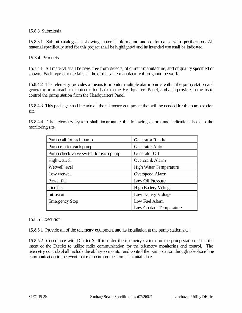
SPEC-15-20 Sanitary Sewer Specifications (07/2002) Lakehaven Utility District
15.8.3 Submittals 15.8.3.1 Submit catalog data showing material information and conformance with specifications. All material specifically used for this project shall be highlighted and its intended use shall be indicated. 15.8.4 Products 15.7.4.1 All material shall be new, free from defects, of current manufacture, and of quality specified or shown. Each type of material shall be of the same manufacture throughout the work. 15.8.4.2 The telemetry provides a means to monitor multiple alarm points within the pump station and generator, to transmit that information back to the Headquarters Panel, and also provides a means to control the pump station from the Headquarters Panel. 15.8.4.3 This package shall include all the telemetry equipment that will be needed for the pump station site. 15.8.4.4 The telemetry system shall incorporate the following alarms and indications back to the monitoring site.
Pump call for each pump Generator Ready Pump run for each pump Generator Auto Pump check valve switch for each pump Generator Off High wetwell Overcrank Alarm Wetwell level High Water Temperature Low wetwell Overspeed Alarm Power fail Low Oil Pressure Line fail High Battery Voltage Intrusion Low Battery Voltage Emergency Stop Low Fuel Alarm
Low Coolant Temperature 15.8.5 Execution 15.8.5.1 Provide all of the telemetry equipment and its installation at the pump station site. 15.8.5.2 Coordinate with District Staff to order the telemetry system for the pump station. It is the intent of the District to utilize radio communication for the telemetry monitoring and control. The telemetry controls shall include the ability to monitor and control the pump station through telephone line communication in the event that radio communication is not attainable.
Lakehaven Utility District Sanitary Sewer Specifications (07/2002) SPEC-15-21
15.8.5.3 All necessary terminations shall be completed to make the telemetry system function at the pump station site. 15.8.5.4 The District shall be responsible for making all necessary changes needed at the Headquarters monitoring site to make the pump station operational once the District has completed all necessary telemetry and the generator and pump station equipment has been tested and accepted by the District. The District will charge a one-time fee for this work, based on the actual cost for the District to provide the necessary work. This eliminates the potential liability for any potential damage from interruption of the telemetry monitoring and control systems for the pump stations and treatment plants. These interruptions, or programming failures, have the potential to affect emergency response for Field and Plant emergencies and process control for the treatment plants. 15.9 OPERATION & MAINTENANCE MANUALS & SPARE PARTS 15.9.1 Description Of Work 15.9.1.1 This section covers furnishing operation and maintenance manuals and spare parts for the pump station. 15.9.2 Standards And Codes 15.9.2.1 All materials and equipment specified herein shall, within the scope of UL Examination Services, be listed by the Underwriter's Laboratories for the purpose for which they are used and shall bear the UL label. 15.9.2.2 All materials and equipment specified herein shall conform with all applicable NEMA, ANSI, and IEEE standards. 15.9.2.3 All materials and equipment specified herein and their installation methods shall conform to the latest published version of the National Electrical Code and all applicable local codes. 15.9.3 Submittals 15.9.3.1 Submit catalog data showing material information and conformance with specifications. All material specifically used as spare parts shall be highlighted and its intended use shall be indicated. 15.9.4 Products 15.9.4.1 All material shall be new, free from defects, of current manufacture, and of quality specified or shown. Each type of material shall be of the same manufacture throughout the work.
SPEC-15-22 Sanitary Sewer Specifications (07/2002) Lakehaven Utility District
15.9.5 Spare Parts 15.9.5.1 The following shall be the list of spare parts by quantity and manufacture. Model numbers can be referenced from the specified submittals of the material and equipment specified herein. 15.9.5.2 Provide one (a) set of three (3) motor heaters for each type of magnetic starter, manufactured by Square D. 15.9.5.3 Provide one (1) set of three (3) contact kits for each type of magnetic starter, manufactured by Square D. 15.9.5.4 Provide one (1) set of three (3) of each type of fuse that is used in the pump station electrical and telemetry system, manufactured by Gould Shawmut. 15.9.5.5 Provide one (1) box of ten (10) of each type of indicator lamps that are used in the control panels, manufactured by General Electric. 15.9.5.6 Provide one (1) of each type of indicator light socket, with transformer, that is used in the control panels, manufactured by Square D. 15.9.5.7 Provide two (2) of each type of control relay and timer delay relays with bases that are used in the control panels. Control relays are manufactured by Idec and the timer delay relays are manufactured by Syrelec. 15.9.5.8 Provide one (1) of each type of contact blocks that are used in the control panels, manufactured by Square D. 15.9.5.9 Provide one (1) of each type of magnetic starter coils that are used in the control panels, manufactured by Square D. 15.9.5.10 Provide one (1) each of every type of PLC card, including the CPU, that is used in the PLC. 15.9.5.11 Provide one (1) Milltronics remote programmer. 15.9.5.12 Provide one (1) Diversified Electronics phase fail relay. 15.9.5.13 Provide one (1) Isolatrol Power Filter. 15.9.5.14 Provide one (1) Condor 24VDC Power Supply. 15.9.5.15 Provide one (1) Systems Interface battery charger.
Lakehaven Utility District Sanitary Sewer Specifications (07/2002) SPEC-15-23
15.9.5.16 There shall be a small cabinet mounted in the service equipment enclosure that will house all of the electrical spare parts that are provided with the pump station. The cabinet shall be watertight and labeled "SPARE PARTS." 15.9.6 Operation & Maintenance Manuals 15.9.6.1 The Supplier shall prepare and assemble four (4) copies of detailed Operation & Maintenance Manuals. All Operation and Maintenance Manuals shall also be provided in Microsoft Word 97 electronic format. All associated drawings shall be provided in Autocad 2000 electronic format. The manuals shall include, but not be limited to, the following information: 15.9.6.2 Complete factory authorized repair, maintenance , and troubleshooting manuals for each piece of equipment that is used in the construction of the pump station. 15.9.6.3 These manuals shall provide complete assembly and disassembly instructions, with mechanical and electrical diagrams and schematics that relate to all of the appropriate equipment. 15.9.6.4 The Operation & Maintenance Manuals shall include preventative maintenance procedures, troubleshooting guides and procedures, calibration procedures, testing procedures and replacement information for all components. 15.9.6.5 The Operation & Maintenance Manuals shall include written procedures for all modes of operation of the emergency system and the equipment associated therewith. 15.9.6.6 The Operation & Maintenance Manuals shall include all electrical systems and mechanical schematics for the pump station and associated equipment. 15.9.6.7 The Operation & Maintenance Manuals shall include exploded views of the mechanical and electrical equipment, with all parts being identified. 15.9.6.8 The Operations & Maintenance Manuals shall include complete electrical "as-built" drawings of the complete electrical system of the generator and its controls. All drawings shall incorporate the wire numbers that correspond with the actual field wiring. One drawing shall show the entire electrical system of the generator and the controls. Additional drawings shall show individual electrical and control systems. The drawings shall include all electronic schematics of all electronic boards and controllers. These drawings shall be provided on 11”x17” paper, and also in Autocad 2000 electronic format. 15.9.6.9 The Supplier shall supply any available factory training videos that would assist in the operation, repair, and troubleshooting of the pump station equipment. 15.9.6.10 The Operation & Maintenance Manuals shall be assembled and indexed by section and put into D-ring binders. The Contractor shall include their contact information for dealer service for all pump station equipment. This shall include distributors and vendors for all pump station equipment.
Lakehaven Utility District Sanitary Sewer Specifications (07/2002) SPEC-16-1
SECTION 16
PUMP STATION STANDBY GENERATOR SYSTEM SPECIFICATIONS
16.1 General 16.1.1 Description Of Work 16.1.1.1 It is the intent that these specifications will describe the minimum acceptable specifications for a diesel-powered, three-phase, 480VAC stationary emergency generator set (Genset). 16.1.1.2 Work Included: Furnish all labor, materials, equipment, services, and incidentals required to provide a complete and operable standby engine-generator system. Materials and equipment shall be new and of best quality, as specified. The work shall include, but not be limited to: (1) Diesel fuel engine-generator set, complete with weatherproof enclosures for outdoors, in line
direct type load bank, exposed installation and having appurtenances necessary for full-time, automatic operation, in addition to those accessories specified hereinafter.
(2) Fuel tank, fuel piping and accessories shall be an integral part of the engine generator set.
The diesel fuel tank shall be installed in the generator set’s base, pre-plumbed with fuel gauge, low fuel alarm, leak detector alarm, drain valve and vented fill cap. The fuel tank shall be sized for 72 hours of run time at a minimum of 50% of total capacity of the generator set. The sub-base fuel tank shall be UL, double-wall construction, with alarm sensor to detect leakage.
(3) Automatic starting and shutdown controls, starting batteries, battery rack, charger, load bank,
generator controls and rupture proof integral fuel tank. (4) Exhaust system complete with flexible connectors, silencer, exhaust piping, insulation and
supports for silencer and exhaust pipe. (5) Weather proof insulated enclosure and all Washington State certifications for emissions
standards and licensing. (6) Manufacturing: Engine-Generator system shall be manufactured and assembled by Kohler,
Onan, or Caterpillar. The Genset shall be a manufactured unit that will be warranted in its entirety by the supplier.
SPEC-16-2 Sanitary Sewer Specifications (07/2002) Lakehaven Utility District
16.1.2 Quality Assurance 16.1.2.1 Comply with all laws, ordinances, codes, rules and regulations of local, State and Federal authorities having jurisdiction over the work specified herein. 16.1.2.2 Provide permits and inspection in accordance with all applicable City, County, State and Federal Codes. 16.1.2.3 Reference Standards: All work and equipment provided under this chapter shall be in accordance with the below noted standards or their amendments: (1) National Electric Manufacturers Association (NEMA) Publication: MG 1-1978 Motors and Generators. (2) National Fire Protection Association (NFPA) Publications:
a. NFPA 30 (1977) - Flammable and Combustible Liquid Code. b. NFPA 37 (1979) - Standard for the Installation and Use of Stationary Combustion
Engines and Gas Turbines.
16.1.3 Submittals 16.1.3.1 Shop Drawings: Check the shop drawing submittal to verify that all the details and data required below are included. If the submittal is not complete, it cannot be reviewed and will be returned for completion. Submit shop drawings that include the following information: (1) Floor layout drawings for the engine-generators, showing location dimensions for all
connections (including electrical, fuel, exhaust, cooling water, and controls), and base dimensions.
(2) Composite assembly drawing of the complete engine-generator, showing dimensions and weight of the unit and locations of all auxiliary equipment; in front, rear, and both side elevations.
(3) Mounting details, including seismic anchorage.
(4) Specification sheets showing performance data and engineering details adequate to demonstrate compliance with specifications for:
a. Engine
b. Generator and Voltage Regulator
c. Base Assembly
d. Engine Control Panel, with all components
e. Jacket Water Heater
f. Governor
Lakehaven Utility District Sanitary Sewer Specifications (07/2002) SPEC-16-3
g. Battery System
h. Battery Charger
i. Exhaust Silencer and exhaust system
j. Load bank system
k. Alarms
l. Torsional analysis of engine and generator
m. Housing
16.1.3.2 Electrical interconnection diagram, including generator, voltage regulator, control panel, circuit breaker, batteries, jacket heater, switches and accessories. 16.1.3.3 Complete identification of all components and materials by manufacturer, model number, rating and material. 16.1.3.4 Complete engine and generator voltage dip and load data. Provide calculations to show compliance with specified performance requirements specifically prepared for the project. 16.1.3.5 Shop drawings of the housing, showing the dimensions and weight of the unit and locations of all auxiliary equipment; in front, rear, and both side elevations. This shall include a complete bill of materials. 16.1.3.6 Single- line generator power diagrams. 16.1.3.7 Wiring diagrams for generator excitation and regulation circuits, alarm circuits, and instrument circuits. These diagrams shall be one complete drawing that shows individual wires that are numbered and corresponding to the actual wiring of the Genset and its controls. 16.1.3.8 Elementary control diagram and separate wiring diagram for automatic engine starting and protective shutdown controls. Show a wire number for every control circuit wire. Include a comprehensive description of operation. 16.1.3.9 Complete surface preparation and finish data for the engine, generator, cabinet, panels, frame, housing, and other surfaces. 16.1.3.10 One (1) copy of the manufacturer's installation and maintenance instructions, to assist in review of the Shop Drawings. 16.1.3.11 Detailed description of the field testing program, including descriptions of the tests, testing equipment, reporting procedure, and criteria for the test passing or failure. (This may be a separate submittal made at a later time, but not later than thirty (30) days before the tests.) 16.1.3.12 Complete bill of materials for all components and list of all recommended spare parts.
SPEC-16-4 Sanitary Sewer Specifications (07/2002) Lakehaven Utility District
16.1.3.13 Factory Test Report: After fabrication and testing, but before shipping from the factory, submit results of the factory test for review. The factory generator test shall consist of a load bank test that shall be done at 10% increments and documented as to the voltage and amperage readings and the vital engine readings during this testing procedure. Do not ship any generator units until the factory test results have received approval by Lakehaven Utility District. 16.1.3.14 Field Test Report: Submit field test report for review within fifteen (15) days of the time of completion of the field test. 16.1.4 Operation & Maintenance Manual: The Supplier shall prepare and assemble (5) copies of detailed Operation & Maintenance manuals. The Supplier shall transmit one copy of the Operation & Maintenance manual in an electronic format that is Microsoft compatible. The manuals shall include, but not be limited to, the following information: 16.1. 4.1 Complete factory authorized repair, maintenance , and troubleshooting manuals for each piece of equipment that is used in the construction of the Genset. 16.1.4.2 These manuals shall provide complete assembly and disassembly instructions, with mechanical and electrical diagrams and schematics that relate to all of the appropriate equipment. 16.1.4.3 The Operation & Maintenance manuals shall include preventative maintenance procedures, troubleshooting guides and procedures, calibration procedures, testing procedures, and replacement of all components. 16.1.4.4 The Operation & Maintenance manuals shall include written procedures for all modes of operation of the emergency system and the equipment associated with it. 16.1.4.5 The Operation & Maintenance manuals shall include all electrical systems and mechanical schematics for the Genset. 16.1.4.6 The Operation & Maintenance manuals shall include exploded views of the generator and engine with all parts being identified. 16.1.4.7 The Operations & Maintenance manuals shall include complete electrical "as-built" drawings of the entire electrical system of the generator and its controls. All drawings shall have the wire numbers that correspond with the actua l field wiring. One drawing shall show the entire electrical system of the generator and the controls. This shall include the wiring numbers and all point-to-point terminals and terminations of all of the electrical components that make up the emergency generator system. Additional drawings shall show individual electrical and control systems. The drawings shall include all electronic schematics of all electronic boards and controllers. These drawings shall be provided on 11” X 17” paper and also in electronic format that is AUTOCAD version 2000 compatible. 16.1.4.8 The Supplier shall supply any available factory training videos that would assist in the operation, repair, and troubleshooting of the Genset.
Lakehaven Utility District Sanitary Sewer Specifications (07/2002) SPEC-16-5
16.1.4.9 The Operation & Maintenance manuals shall be assembled and indexed by section and put into D-ring binders. The Contractor shall include their contact information for dealer service for the Genset. 16.1.5 Affidavit: Furnish an affidavit from the engine-generator supplier, stating that the system has been properly installed and tested, and is ready for full-time operation in conformance with these specifications. 16.1.6 Guarantee. The Supplier shall guarantee the complete engine-generator system for a period of two (2) years after final acceptance by Lakehaven Utility District. The supplier shall be able to respond to all warranty and emergency work within two (2) hours, to insure the critical operation of the Genset. The District will have the right to make the repairs internally, or contract out the necessary services to make the repairs, if the Supplier is unable to respond in the appropriate time frame. The supplier will then be billed for all expenses incurred by the District to make the warranty repairs and the Supplier shall reimburse the District upon receipt of such billing notice. 16.1.7 Products 16.1.7.1 Standby Engine-Generator Sets 16.1.7.2 General: Each engine-generator shall be a factory assembled package of new and current equipment, consisting of: engine, generator, controls, and other accessories, as specified and as may be required for a complete and operable assembly, capable of automatic start-up and shutdown. 16.1.7.3 The complete engine-generator assembly shall be provided by the manufacturer of the generator or the engine manufacturer's distributor, so there is one source for supply and responsibility. This responsibility shall include coordinating the installation and successfully operating the specific engine-generator sets. The complete engine-generator assembly shall be in accordance with the National Electrical Code, state and local regulations. 16.1.7.4 Provide each engine-generator permanently mounted on a welded steel base for anchoring to a concrete pad, with vibration isolators provided between the engine-generator and the welded base. 16.1.7.5 Ratings and Performance: The emergency generator shall be rated continuous standby (defined as continuous for the duration of any power outage), 480VAC, 3-phase, 4-wire, with a minimum 0.89 power factor. The generator shall have a full size rated neutral capacity. All generator sets shall be sized by a licensed Professional Engineer for the loads that will be served by the generator set. All motor loads shall be sized as across the line starting in determining the size of the generator. 16.1.7.6 The generator will not be required to parallel any other source.
SPEC-16-6 Sanitary Sewer Specifications (07/2002) Lakehaven Utility District
16.1.7.7 The generator set shall be capable of starting and operating all of the pumps at the Pump Station. The pumps will not start simultaneously. The instantaneous voltage dip shall not exceed 15%. 16.1.7.8 All mounting hardware for all equipment that is used in the construction of the genset shall be type 316 Type Stainless Steel. 16.1.8 Engines: The supplier shall size the engine to match with the generator for the rated load of the generator. The engine shall be equipped with the following: 16.1.8.1 Engine-driven or electric fuel transfer pump capable of lifting fuel 16 feet, fuel filter, electric solenoid fuel shut-off valve, and a fuel distribution system with an isochronous governor on 160 kW and larger generators. Generators smaller than 160 kW shall be equipped with an isochronous governor capable of +0.25 percent steady-state frequency regulation. 16.1.8.2 12-Volt positive engagement solenoid shift-starting motor. 16.1.8.3 35-Ampere minimum automatic battery charging alternator with solid-state voltage regulation. 16.1.8.4 Positive displacement, full pressure lubrication oil pump, cartridge oil filters, dipstick, and oil drain. 16.1.8.5 Dry-type replaceable air cleaner elements. NOTE: Engines requiring glow plugs will not be acceptable when NFPA-99 ten-second transfer requirement must be met. 16.1.8.6 The naturally aspirated or turbocharged engine shall be fueled with No. 2 diesel, 4-cycle, liquid-cooled by a Unit-Mounted radiator, blower fan, water pump, thermostat, and radiator duct flange shall properly cool the engine with up to 0.5 inches H2O static pressure on the fan. 16.1.8.7 Block heater, 1500 watt, size 240 Volt AC; thermostatically controlled to maintain engine coolant at proper temperature to meet the start-up requirement of NFPA-99 Regulation. The block heater shall be supplied by the generator set manufacturer. The outlet shall be externally mounted with a recessed male outlet. The outlet shall be INSULGRIP series, manufactured by Hubbell. The outlet cover shall be a WP1, manufactured by Hubbell.
Lakehaven Utility District Sanitary Sewer Specifications (07/2002) SPEC-16-7
16.1.8.8 The diesel fuel tank shall be installed in the generator set’s base, pre-plumbed with fuel gauge, low fuel alarm, leak alarm, drain valve and vented fill cap. The fuel tank shall be equipped with quick-disconnect on the fuel line, so that the generator can be hooked up to a portable fuel source for long term emergency use. The fuel tank shall be sized for 72 hours at 50% load. The sub-base fuel tank shall be UL, rupture-proof, double-wall construction, with alarm sensor to detect leakage. 16.1.8.9 Batteries: Provide starting batteries mounted in attached battery racks with non-conducting bottoms. The batteries shall be guaranteed for two (2) years and the manufacturer shall install a new battery for any battery found defective within the guarantee period. Batteries shall be mounted in a separate vented battery compartment that is accessible for maintenance and replacement. Batteries shall be the deep cycle, lead acid type, wet cell, selected to provide engine break-away current for one second followed by a full cranking cycle, as specified above, with a resultant voltage not less than 0.85 volts per cell and at a battery temperature of 20 degrees F; engine temperature shall be maintained by the jacket heater for a 20 degrees F ambient temperature. The battery shall have a protective polyglass removal cover. 16.1.8.10 Battery Charger: For each engine, provide a charger of the automatic dual-rate type. A DC ammeter, DC voltmeter, fused AC input and DC output, and charge rated selector switch shall be included. The charger shall operate on 120 VAC equipped for conduit installation. The battery charger shall be equipped with a high and low battery voltage alarm. There shall be a dry set of contacts for each alarm. Each charger shall be capable of recharging its battery to full charge within eight (8) hours after a full cranking cycle. The outlet shall be externally mounted, with a recessed male outlet. The outlet shall be INSULGRIP series, manufactured by Hubbell. The weatherproof outlet cover shall be WP1, manufactured by Hubbell. 16.1.8.11 Gasproof, seamless, stainless steel, flexible exhaust connection, and engine exhaust silencer rated for hospital use. Exhaust noise shall be limited to 85 dba, as measured at ten (10) feet in a free-field environment. 16.1.8.12 Safety Guards: Provide safety guards for the exhaust manifold and turbocharger. 16.1.8.13 Pipe crankcase shall drain to the outside of the engine base frame and terminate with a plugged globe valve; conveniently located for crankcase oil changing. 16.1.8.14 Engine exhaust: Schedule 40 black steel pipe conforming to ASTM A 120 with condensate drains at low points. Provide thermal blanketing on the exhaust manifold for personnel safety. 16.1.8.15 Exhaust piping and silencer insulation thickness (hospital silencer): four (4) inches. The exhaust piping and silencer is located inside the exhaust duct for the radiator housing, with the stack extended out through the top, and with a rain cap on the exhaust pipe. 16.1.8.16 The radiator must be accessible to fill and have a sight gauge to read the level in the radiator. The radiator drain shall be plumbed outside of the engine base frame, with a drain extension to drain the coolant, and terminate with a plugged globe valve.
SPEC-16-8 Sanitary Sewer Specifications (07/2002) Lakehaven Utility District
16.1.9 Generators 16.1.9.1 The alternator shall be salient-pole, brushless, 12- lead reconnectable, and self-ventilated; of drip-proof construction, with amortisseur rotor windings and skewed stator for smooth voltage waveform. The insulation shall meet the NEMA standard (MG1-22.40 and 16.40) for Class H and be insulated with epoxy varnish to be fungus resistant per MILE-4970A. The excitation system shall be of brushless construction, controlled by a solid-state voltage regulator capable of maintaining voltage within plus or minus two percent (2%) at any constant load from 0 to 100 percent of rating. The regulator must be protected from the environment by conformal coating. 16.1.9.2 Upon one-step application of any load up to 90 percent of the rated load at 0.8 power factor, the vo ltage dip shall not exceed 15 percent and shall recover to two percent (2%) of rated voltage within one (1) second. 16.1.9.3 The generator shall be capable of sustaining at least 250 percent of rated current for at least ten (10) seconds under a three-phase symmetrical short by inherent design or by the addition of an optional current boost system. An optional current boost system addition shall be at the cost of the Contractor. 16.1.9.4 A resettable line current sensing circuit breaker, with inverse time versus current response, shall be furnished, which protects the generator from damage due to its own high current capability. This breaker shall not trip within the ten (10) seconds specified above to allow selective tripping of downstream fuses or circuit breakers under a fault condition. This breaker shall not automatically reset, preventing restoration of voltage if maintenance is being performed. Field current-sensing breaker will not be acceptable. Breakers shall be sized for the full load of the generator. Breakers shall be rated for 600 VAC and shall be manufactured by Square D. 16.1.9.5 The generator, having a single maintenance-free bearing, shall be directly connected to the flywheel housing with a semiflexible coupling between the rotor and the flywheel. 16.1.9.6 Frequency regulation shall be isochronous plus or minus 0.25 from no- load to rated load. 16.1.10 Instrument Panel. An instrument panel shall include: 16.1.10.1 The generator controller shall be able to provide a digital readout for engine oil pressure, coolant temperature, engine RPM, system DC voltage, engine running hours, system diagnostic codes for troubleshooting and operation, generator AC amperage, generator AC voltage, voltage adjust rheostat, and generator frequency. 16.1.10.2 Controller. Set-mounted controller capable of facing right, left, or rear, shall be vibration- isolated on the generator enclosure. The controller shall be capable of being remote-mounted. The microprocessor control board shall be conformal coated. Relays will only be acceptable in high-current circuits. The controller shall be located at a level that can be viewed
Lakehaven Utility District Sanitary Sewer Specifications (07/2002) SPEC-16-9
and operated from a standing position on the ground. The height shall not exceed six (6) feet. The controller shall have all of the control wiring for the generator and alarm and monitoring terminations inside of the controller. The controller orientation shall be confirmed during the submittal review and approval process. Group all service outlets at the location of the controller. 16.1.10.3 Circuitry shall be of plug- in design for quick replacement. Controllers shall be equipped to accept a plug-in device capable of allowing maintenance personnel to test controller performance without operating the engine. The supplier shall supply the test controller and all of the applicable cabling that is required to operate it. The controller shall include: 16.1.10.4 Fused DC circuits. 16.1.10.5 Complete two (2) wire start/stop control which can operate on closure of a remote contact. 16.1.10.6 Speed sensing and a second independent starter motor disengagement systems shall protect against starter engagement with a moving flywheel. Battery charging alternator voltage will not be acceptable for this purpose. 16.1.10.7 The starting system shall be designed for restarting in the event of a false engine start, by permitting the engine to completely stop and then re-engage the starter. 16.1.10.8 Cranking cycler with ten (10) second ON and OFF cranking periods. 16.1.10.9 Overcrank protection designed to open the cranking circuit after 60 seconds, if the engine fails to start. 16.1.10.10 Circuitry to shut down the engine when signals for high coolant temperature, low oil pressure, or overspeed are received. 16.1.10.11 Engine cool down timer, factory set at five (5) minutes, to permit unloaded running of the standby set after transfer of the load to normal. 16.1.10.12 Overvoltage protection will shut down the unit after one (1) second of 15 percent or more overvoltage. NOTE: Sensitive equipment may suffer damage in less than one (1) second of an overvoltage condition. On- line equipment requiring faster shutdown should have its own overvoltage protection. 16.1.10.13 Three (3) position (Automatic - OFF - TEST) selector switch. In the TEST position the engine shall start and run regardless of the position of the remote starting contacts. In the Automatic position, the engine shall start when contacts in the remote control circuit close and stop five (5) minutes after those contacts open. In the OFF position, the engine shall not start, even though the remote start contacts close. This position shall also provide for immediate shutdown in case of an emergency. Reset of any fault shall also be accomplished by putting the switch to the OFF position.
SPEC-16-10 Sanitary Sewer Specifications (07/2002) Lakehaven Utility District
16.1.10.14 Indicating lights to signal: (1) Switch "OFF" (flashing red)
(2) Overcrank (red)
(3) Emergency stop (red)
(4) High water temperature (red)
(5) Overspeed (red)
(6) Low oil pressure (red)
(7) * High battery voltage (red)
(8) * Low battery voltage (red)
(9) * Low fuel (red)
(10) * System ready (green)
(11) Pre alarm high water temp. (yellow)
(12) * Pre alarm low oil pressure (yellow)
(13) * Low coolant temp. (red)
* Required to meet NFPA-99 Regulations. 16.1.10.15 Test button for indicating lights. 16.1.0.16 Alarm horn with silencer switch. 16.1.10.17 Alarm Outputs: Provide one (1) set of normally-closed, dry (i.e., non-energized) output contacts for each alarm and shutdown condition that is specified. The contacts shall be actuated for any one or more of the shutdown conditions. The contacts shall remain activated during the entire period of the abnormal condition and reset shall be automatic. All alarm contacts shall be wired to a terminal strip. 16.1.10.18 All generator and control wiring shall be permanently imprinted with the wire numbers on the insulation, the wiring, or on heat-shrink, permasleeve, permanently imprinted wire markers. The electrical drawings shall have the wire numbers on them. 16.1.11 Housing 16.1.11.1 The weatherproof housing shall be constructed of 14 gauge steel. All construction hardware used in the construction of the housing shall be type 316 stainless steel. The housing shall be constructed so that water will not pond on the roof of the housing. 16.1.11.2 The entire housing shall have a primer coat of TNEMEC epoxy. The inside of the housing shall be TNEMEC series 66 Hi-Build epoxy line, applied to a thickness of five (5) mils. The outside of the housing shall be TNEMEC series 66 hi-build epoxy line, applied to a thickness of five (5) mils. The outside shall then receive a finish coat of TNEMEC series 73
Lakehaven Utility District Sanitary Sewer Specifications (07/2002) SPEC-16-11
Endurashield, applied to a thickness of three (3) mils. The color shall be TNEMEC Lt. Gray-ANSI No. 70. The Supplier shall provide a color schedule to Lakehaven Utility District for approval. 16.1.11.3 An insulation package shall be provided; attached to the interior of the housing to reduce dba to a level of 70 dba @ 20 feet. The insulation package shall be provided and installed by the supplier. 16.1.11.4 The doors/side panels shall be locking with padlock handles. Doors/side panels shall be easily removed for servicing. The enclosure shall have an adequate number of doors to permit access and maintenance to all equipment within the enclosure. All latches and hinges shall be type 316 stainless steel and capable of being padlocked. 16.1.11.5 Louvers shall be provided at the generator and radiator ends of the housing. The louvers shall be power-open and self-closing. 16.1.11.6 The top-mounted exhaust silencer shall have a heat shield, protecting personnel from hot surfaces. A rainshield shall be provided over the exhaust opening. 16.1.11.7 Install interior lights that will be battery-powered from the generator batteries and are switchable from inside of the housing. The lights shall be lens-protected and gasketed. 16.1.11.8 Install one 20 Amp, 110 VAC, double duplex outlet inside of the enclosure, with a weatherproof cover that will be energized when the generator is running. The circuit shall be fused. 16.1.11.9 The enclosure shall be equipped with four internal and four external 12 VDC switched lights to illuminate the interior enclosure area and the external work area. The lights shall be weatherproof and run off of the generator batteries. The lights shall all be of the same size, type and manufacture. The internal and external lights shall be on separate light switches that are spring-return timers with a 30-minute duration of run time before they automatically shut off. 16.1.11.10 The housing shall have intrusion switches installed on all compartment doors that can open. They shall be wired in series. The wiring shall be protected by wire lume and secured to the internal walls for support. The wiring shall terminate on the terminal strip for the alarm wiring. 16.1.11.11 Install red phenolic placards on the interior of the housing adjacent to the generator control panel that explain all modes of operation and identify supplier’s contact business information, including 24-hour emergency numbers for service. 16.1.11.12 The housing shall be as manufactured by Excel Engineering, LTD, Vancouver, Canada; Viking Marine Industries, Inc.; Alum-Tek Industries Ltd.; or an Approved Equal.
SPEC-16-12 Sanitary Sewer Specifications (07/2002) Lakehaven Utility District
16.1.12 Load Bank 16.1.12.1 A self-contained, permanently mounted, duct-radiator type load bank; complete with controls, contactors, louvers, necessary wiring and installation, shall be provided so as to become part of the generator system specified herein. 16.1.12.2 The weatherproof load bank system shall be provided and installed by the supplier. The load bank shall be located within the generator set enclosure. 16.1.12.3 This system shall be completely manual in operation. 16.1.12.4 The step load bank provided shall be sized as to accommodate loads of 25 percent to 100 percent in 25 percent increments up to the rated KW of the generator specified herein. 16.1.12.5 The load bank, complete with controls, shall be manufactured by Simplex. 16.1.13 Execution 16.1.13.1 Testing And Run-In 16.1.13.2 General: Perform tests to determine proper operation and capacity of the equipment and to demonstrate compliance with these specifications. All equipment that fails any test will be rejected. Complete re-testing will be required, after corrections or modifications, for any equipment that has previously failed any test. All field tests shall be witnessed by a District representative. 16.1.13.3 Factory Tests: Test the engine-generator in the factory to assure compliance with these specifications and NEMA MG-1. 16.1.13.4 Field Tests: 16.1.13.4.1 General: Field test the engine-generator to demonstrate the units are in compliance with these specifications and are ready for service. 16.1.13.4.2 Schedule the field tests after delivery and installation of the generator is complete and the unit has been serviced, tested, and adjusted, and is ready for use. The generator shall be tested on site to verify proper operation and phase rotation. The supplier shall make all corrections for proper rotation. 16.1.13.4.3 Provide written notice of the scheduled dates for the field tests to the District at least ten (10) working days prior to the field test date. The notice shall include a written test schedule; listing the tests, the test procedure, the criteria for a satisfactory test, and special measurement equipment to be employed subject to approval by Lakehaven Utility District.
Lakehaven Utility District Sanitary Sewer Specifications (07/2002) SPEC-16-13
16.1.13.4.4 Make repairs and adjustments as required to achieve satisfactory performance of the engine-generator unit. If repairs or adjustments are made during the tests, perform additional testing as required by Lakehaven Utility District at no additional cost. 16.1.13.4.5 Make typewritten records of the tests and, within 15 days, submit three (3) copies of the test records to the District. The test records shall indicate the test criteria and arrangement, the time of the test, the results, and pertinent data such as voltage, frequency, kilowatts, power factor, load current, oil pressure, water temperature, and ambient temperature. Record pertinent data for each test and at least every 30 minutes, when the test requires more than 30 minutes. 16.1.13.4.6 Confirm the voltage dip characteristics by field testing. Failure of this field test shall constitute evidence that the equipment has not met the voltage dip criterion; replace or modify the equipment as necessary to obtain satisfactory operation as specified. Under no circumstances will equipment with a voltage dip greater than specified be acceptable. 16.1.13.5 Alarm, Control, and Equipment Tests: Demonstrate each alarm and safety shutdown provision by causing the abnormal condition, unless an alternative test condition has been approved by Lakehaven Utility District prior to the scheduling of the tests. Operate each control circuit and device to demonstrate its proper operation. Demonstrate the battery charger and jacket water heater operation. 16.1.13.6 Fuel System: Demonstrate that the fuel system operates to the satisfaction of all regulating agencies and Lakehaven Utility District. 16.1.13.7 Operational Tests: Simulate a power failure in order to demonstrate the proper operation of the switchboard and engine-generator. Demonstrate motor starting capability by starting and running the specified motor loads. Measure and record voltage dip to demonstrate conformity to these specifications. Provide special equipment for this test. Show that phase rotation of the engine-generator and the existing power are compatible at the site. 16.1.13.8 Endurance Tests: Operate the engine-generator for 1/2 hour at one-half its kW rating. Operate the engine-generator for six (6) hours continuously at 100 percent of its kW rating. 16.1.13.9 Provide load banks, fuel, test equipment, labor, materials, and all other equipment and services required for all tests; all to be included in the Contract bid price. 16.1.13.10 The Supplier shall fill the fuel tank after all startup, on-site testing, and training have been completed. 16.1.13.11 The Generator Supplier shall supply the following spare parts for the emergency generator. The spare parts shall be new and of the same type as furnished in the construction of the emergency generator. (1) One spare air filter of each type supplied.
(2) One spare oil filter of each type supplied.
(3) One spare fuel filter of each type supplied.
SPEC-16-14 Sanitary Sewer Specifications (07/2002) Lakehaven Utility District
(4) One set of belts of each type supplied.
(5) One spare complete battery charger of each type supplied.
(6) One spare complete generator controller that is prewired to match the generator that is being supplied. This shall be complete with all components that make up the generator control panel.
(7) Two spare interior and exterior lights of each type supplied.
(8) One spare block heater of each type supplied.
(9) One set of three (3) of each type of fuse that is used in the construction of the generator and its equipment.
16.1.14 District Orientation 16.1.14.1 Furnish a representative of the engine-generator supplier to meet with selected representatives of Lakehaven Utility District at the time of the final acceptance tests, to review the operation and parts books, correct starting and control methods, and recommended preventive maintenance procedures (assume one (1) day - 8 hours of instruction). All associated testing and training costs shall be included in the Contract bid price. 16.1.14.2 Provide the Operation and Maintenance Manuals to Lakehaven Utility District at least one week prior to the training sessions. There shall be a training schedule provided that shall be approved by Lakehaven Utility District prior to the factory training. 16.1.14.3 Lakehaven Utility District reserves the right to videotape the factory training sessions. 16.2 AUTOMATIC TRANSFER SWITCH 16.2.1 General 16.2.1.1 Description 16.2.1.2 Provisions: Applicable provisions of Section 16.1 of these specifications become a part of this section as if repeated herein. 16.2.1.3 Work Included: Provide a 600 VAC rated automatic transfer switch, complete with controls and accessories, as indicated herein. The transfer switch shall be sized for the full load of the generator. 16.2.2 Reference Standards 16.2.2.1 NEMA Publication: ICS 6-1978 Enclosures for Industrial Controls and Systems 16.2.2.2 UL Publication: 1008-1977 Automatic Transfer Switches (Rev. 1979)
Lakehaven Utility District Sanitary Sewer Specifications (07/2002) SPEC-16-15
16.2.2.3 All material and equipment specified herein and their installation methods shall conform to the latest published and approved National Electrical code and all other applicable state and local electrical codes. 16.2.3 Submittals 16.2.3.1 Submit shop drawings which include: (1) Dimensioned drawings
(2) Elementary diagrams
(3) Wiring diagrams
(4) Nameplate list
(5) Evidence that the equipment will be provided with all specified accessories, options, features, and characteristics.
(6) Certifications that the equipment is designed and manufactured in conformance with applicable codes and standards.
16.2.4 Operation & Maintenance Manual: The Contractor shall prepare and assemble four (4) copies of detailed Operation & Maintenance manuals. All Operation and Maintenance Manuals shall also be provided in Microsoft Word 97 electronic format. All associated drawings shall be provided in Autocad 2000 electronic format. The manuals shall include, but not be limited to, the following information. 16.2.4.1 Complete factory authorized repair, maintenance , and troubleshooting manuals for each piece of equipment that is used in the construction of the transfer switch. 16.2.4.2 These manuals shall provide complete assembly and disassembly instructions, with mechanical and electrical diagrams and schematics that relate to all of the appropriate equipment. 16.2.4.3 The Operation & Maintenance manuals shall include preventative maintenance procedures, troubleshooting guides and procedures, calibration procedures, testing procedures, and replacement of all components. 16.2.4.4 The Operation & Maintenance manuals shall include written procedures for all modes of operation of the emergency system and the equipment associated with it. 16.2.4.5 The Operation & Maintenance manuals shall include all electrical systems and mechanical schematics for the transfer switch. 16.2.4.6 The Operation & Maintenance manuals shall include exploded views of the transfer switch, with all parts being identified. 16.2.4.7 The Operations & Maintenance manuals shall include complete electrical "as-built" drawings of the entire electrical system of the transfer switch and its controls. All drawings shall
SPEC-16-16 Sanitary Sewer Specifications (07/2002) Lakehaven Utility District
have the wire numbers that correspond with the actual field wiring. One drawing shall show the entire electrical system of the transfer switch and the controls. Additional drawings shall show individual electrical and control systems. The drawings shall include all electronic schematics of all electronic boards and controllers. These drawings shall be provided on 11” X 17” paper and also in electronic format that is AUTOCAD version 2000 compatible. 16.2.4.8 The Contractor shall supply any available factory training videos that would assist in the operation, repair, and troubleshooting of the transfer switch. 16.2.4.9 The Operation & Maintenance manuals shall be assembled and indexed by section and put into D-ring binders, including the Supplier's contact information for dealer service for the transfer switch. 16.2.5 Affidavit: Furnish an affidavit from the transfer switch Supplier, stating that the system has been properly installed and tested, and is ready for full time operation in conformance with these specifications. 16.2.6 Guarantee. The manufacturer shall guarantee the transfer switch system for a period of two (2) years after final acceptance by Lakehaven Utility District. The Supplier shall be able to respond to all warranty and emergency work within 2 hours to insure the critical operation of the emergency power system. The District will have the right to make the repairs internally, or contract out the necessary services to make the repairs, if the Supplier is unable to respond in the appropriate time frame. The Supplier will then be billed for all expenses incurred by the District to make the warranty repairs and the Supplier shall reimburse the District upon receipt of such invoice. . 16.2.7 Products 16.2.7.1 Automatic Transfer Switch 16.2.7.1.1 General: An automatic transfer switch shall transfer from the normal service to a standby engine generator in the event of power failure. The switch shall transfer the system back to normal power after normal power has been restored. The switch shall include all controls and accessories. The switch sha ll be UL labeled, shall meet requirements of UL Standard 1008, and shall be suitable for total system transfer, including motor and lighting loads. 16.2.7.2 Construction 16.2.7.2.1 The automatic transfer switch shall be of the mechanically held type. All main power contacts and auxiliary contacts shall be mechanically attached to a common shaft, shall be double-break silver alloy with wiping action, and shall be protected by arcing contacts. Arcing contacts shall close before and open after the main contacts and shall be readily replaceable. Contact design and arrangement shall permit repeated making and breaking of full- load current, in a combination of motor and other loads, without damage to the main contacts.
Lakehaven Utility District Sanitary Sewer Specifications (07/2002) SPEC-16-17
16.2.7.2.2 The switch transfer shall be produced in such a way that a time delay exists between the opening of the closed contacts and the closing of the open contacts. 16.2.7.2.3 All switch and relay contacts, coils, springs, and control elements shall be serviceable, or removable from the front of the mounted switch and accessory assembly, without the removal of either assembly from its compartment and without disconnection of drive linkages, power conductors, or control conductors. 16.2.7.2.4 The enclosure shall be NEMA 3R or NEMA 12 construction, with hinged doors on the front for access to the interior controls. Secure doors by a single point key-locking latch. Provide an enamel paint finish, with a minimum dry film thickness of three (3) mils. 16.2.7.2.5 Cable connections shall be accessible from the front, without removing internal components. 16.2.7.2.6 The transfer switch shall comply with applicable requirements of the Basic Electrical Regulation for control panels. 16.2.7.3 The transfer switch shall have the following features: 16.2.7.3.1 Continuous rating of 600 VAC, 3 phase, [with 3 poles and full neutral bus.] [and 4 pole for accommodating ground fault relaying.] Current rating shall be as shown on the Contract Drawings. 16.2.7.3.2 Adequate line and load lugs for terminating the specified power conductors. 16.2.7.3.3 A terminal strip, with terminals for terminating all external control circuits. Number all terminals using the wire number for the wire terminated. 16.2.7.3.4 Cable wiring with cable ties, secured in place and guarded where subject to mechanical injury. 16.2.7.3.5 Permanently identify each wire at each point of connection, using permanently numbered heat shrink perma-sleeve wiring markers. Electrically common wires shall have the same number. Uniquely number electrically different wires. This shall include all factory-assembled electrical equipment. 16.2.7.4 Controls: The automatic transfer switch shall include the following controls and accessories: 16.2.7.4.1 Three-phase Relay Protection: Three (3) adjustable close differential relays, connected phase-to-phase, all set to drop out at 90 percent and to pick up at 95 percent of nominal voltage. 16.2.7.4.2 Test\Normal\Retransfer Switch: A key operated (Lakehaven Utility District Standard Keymark Lock. The Lock Shop located in Federal Way provides all District key locks.
SPEC-16-18 Sanitary Sewer Specifications (07/2002) Lakehaven Utility District
253-839-3443) test control switch, which shall cause the automatic transfer switch to start the engine, transfer, retransfer, and the like, simulating a power outage. The retransfer function shall be immediate and capable of bypassing the transfer time delay. Mount this switch on the door of the transfer switch compartment. 16.2.7.4.3 Indicating Lights: One each to indicate the switch is supplying "Normal Power" or "Standby Power." One each to indicate “Normal Source Available” and/or “Emergency Source Available." Provide neon type lamps with series resistors, as required, in oil-tight units with clear lenses. Label each light with plastic nameplates engraved "NORMAL," "STANDBY," “EMERGENCY AVAILABLE," and “NORMAL AVAILABLE," respectively. Mount lights on the door of the transfer switch compartment. 16.2.7.4.4 Engine Starting Delay: A timer that, following loss or deterioration of "normal" power, will delay closure of engine starting contact for an adjustable period up to two (2) minutes, to eliminate starts during brief or momentary outages of "normal" power. Set delay at five (5) seconds. 16.2.7.4.5 Transfer Relay: A relay to prevent the transfer to standby until the standby power voltage and frequency are 90 percent of rated values. 16.2.7.4.6 Retransfer Delay: A timer to provide an adjustable delay from two (2) up to 25 minutes (minimum range) before retransfer to "normal" power. If "standby" power fails before the preset delay period elapses, and if "normal" power is within set limits of voltage, override the delay and retransfer immediately. 16.2.7.4.7 Nameplates: An engraved plastic nameplate for every lamp, switch, and other control device or indicator. Identify all switch and control positions. Nameplate wording shall be subject to review by the Engineer. 16.2.7.4.8 Unloaded Generator Operation: A timer that, following retransfer to "normal" power, will maintain the engine in unloaded operation for a fixed period of five (5) minutes, before signaling it to shut down. 16.2.7.4.9 Auxiliary Contacts: Provide (2) sets of normally-open and normally-closed form C contacts, which transfer each time the switch transfers. The relays shall indicate Emergency and Normal position of the transfer switch and Emergency Source and Normal Source Available. 16.2.7.4.10 Transfer Delay: A timer to provide an adjustable delay of one (1) to five (5) seconds in the closing of the open contacts, after the closed contacts have opened. Provide this delay for both transfer and retransfer switch operations. 16.2.7.4.11 Mechanical Interlock: A mechanical interlock that will prevent the simultaneous closing of the normal and emergency contacts.
Lakehaven Utility District Sanitary Sewer Specifications (07/2002) SPEC-16-19
16.2.7.4.12 Electrical Interlock: An electrical interlock that will prevent the simultaneous closing signals to normal and emergency contacts and the interconnection of normal and emergency sources through the control wiring. 16.2.7.4.13 Manual Transfer Handle: A manual transfer switch that is permanently attached and has quick-break and quick-make contact mechanisms that are suitable for manual operation under load. This function shall not require electricity for operation. 16.2.7.4.14 Pump Interlock: Provide control wiring interlock that will not allow the transfer switch to actuate during the time that one of the pumps are running. The motor auxiliary contacts from each pump shall be wired in series with the transfer command, so that the transfer cannot take place while one of the pumps are running. This operating function shall be indicated on the transfer switch drawings. 16.2.7.5 UL Label: The transfer switch shall have a UL label on the unit when it arrives at the site. Absence of the UL label shall be sufficient cause for the unit to be rejected. Provide all of the specified features, options, and accessories. If the manufacturer's standard UL unit does not have the specified features, options or accessories, then provide alternative features, options, or accessories to accomplish the same purpose in a manner similar to that specified, while still providing a unit with a UL label. 16.2.7.6 Current Ratings: The transfer switch shall have continuous ampere rating and a short circuit withstand rating of the appropriate RMS symmetrical ampere rating for the load being served. It shall be the responsibility of the Supplier to provide the calculation documentation to Lakehaven Utility District for review with the submitted design proposal. The transfer switch shall be rated for the full load of the generator. 16.2.7.7 Manufacturer and Model: The automatic transfer switch shall be manufactured by the Genset manufacturer and shall meet the specifications herein. 16.2.7.8 Finish: The finish shall be as recommended by the manufacturer's standard. 16.2.7.9 Factory Tests: Assemble, wire and test the automatic transfer switch to the factory specifications. Conduct tests to assure that every component functions properly. Submit prototype test reports on bus bracing for Lakehaven Utility District approval. 16.2.7.10 The supplier shall provide the following spare parts for the automatic transfer switch. The spare parts shall be new and of the same type as furnished in the construction of the automatic transfer switch. (1) One spare electronic control board for each type that is used the construction of the automatic
transfer switch.
(2) One spare control relay and time delay relay that is used in construction of the automatic transfer switch.
(3) One spare indicating light display that is used in the construction of the automatic transfer switch.
SPEC-16-20 Sanitary Sewer Specifications (07/2002) Lakehaven Utility District
(4) One spare drive actuating motor that is used in the construction of the automatic transfer switch.
16.2.8 Execution 16.2.8.1 Installation. The automatic transfer switch shall be securely mounted inside of the electrical service enclosure. The door shall open freely and close tightly. Repair any defect or damage to the switch, enclosure or paint, to the satisfaction of Lakehaven Utility District. 16.2.8.2 Testing. Field Tests: Demonstrate that the automatic transfer switch operates as specified. Test with the engine-generator and transfer the standby system load, as specified for the engine-generator, at least three (3) times. All field testing shall be done in the presence of a Lakehaven Utility District representative for approval.
Lakehaven Utility District Sanitary Sewer Specifications (07/2002) SPEC-17-1
SECTION 17
MISCELLANEOUS EQUIPMENT 17.1 WATERPROOFING WITH SPECIAL COATINGS 17.1.1 General 17.1.1.1 Description. Provide a liquid applied surface waterproofing coating system especially designed for wastewater treatment facilities. The system shall be applied to the surface of all pump stations and valve vaults noted specifically hereafter: 1. All interior surfaces of the wet well and valve vaults, including the floor slab and the ceiling and the
access tube.
2. All exterior walls, the top surface of the roof slab, and the access tubes.
3. Interior surfaces of the wet well and valve vaults shall be White in color. 17.1.1.2 Quality Assurance 1. Applicator shall be licensed by the Material manufacturer.
2. The Contractor, the Waterproofing Applicator and the Manufacturer of the Waterproofing material shall provide to the District, jointly and severally, a three (3) year written guarantee to repair any leaks in the coating system at no cost to the District, including costs of excavation, costs to prevent interruption of the facility operations, backfilling and all other costs made necessary in repairing leaks or faulty installation. The guarantee shall be signed by the Contractor together with the Applicator and the Manufacturer of the elastomeric waterproofing. This guarantee shall be presented to the District upon completion of the project and acceptance of the project by the District.
17.1.1.3 Submittals 1. Product data describing all products proposed for use including test data sufficient to permit
comparison with the first named product in Section 17.2.2 of these Specifications.
2. Physical samples of the system applied to concrete test pieces.
3. Certification of Applicator licensing by the Material manufacturer.
4. Applicator's review of the installed pump stations, including details and all conditions. When the applicator is satisfied that the surfaces meet the specified requirements, he/she shall furnish a written agreement stating that all aspects of the specified system are compatible with the intended use and that the specified system will perform its function. The Contractor shall be responsible for providing a Class 2 Surface Finish for Walls on all surfaces designated to be waterproofed.
SPEC-17-2 Sanitary Sewer Specifications (07/2002) Lakehaven Utility District
5. Certification that both Applicator and Manufacturer have installed and furnished the proposed system satisfactorily for a period of not less than five (5) years. The certification shall be accompanied by a list of not less than four (4) previous clients (contact person and current telephone number), all of whom may be contracted by the District.
17.1.1.4 Delivery And Storage 1. Deliver in original unopened containers with manufacturer's label indicating the product, manufacture
date and lot number.
2. Store at room temperature.
17.1.1.5 Environmental Conditions. Install waterproofing system only under temperature and weather conditions described as acceptable by system manufacturer. 17.1.1.6 Warning. Apply coating only where adequate ventilation can be provided. Installation of membrane coatings can be hazardous to your health. The Contractor shall provide all required safeguards, breathing equipment, and protective clothing to safeguard workers. 17.1.2 Products 17.1.2.1 General. Protective coatings shall be as specified in Section 17.2 of these Specifications. 17.1.3 Execution 17.1.3.1 Surface Conditions 1. Apply waterproofing no less than 28 days after concrete pour or until passing the ASTM D 4263-8
Wet Mat Test to determine if moisture is in motion.
2. Verify that curing method used for concrete is compatible with deck coating system. 17.1.3.2 Preparation 1. Prepare concrete by sweep blasting to provide a surface profile no less than 3 mils deep.
2. Rout or saw cut all cracks exceeding 1/16-inch in width and fill with sealant specified in Section 12.1.2.10 of these Specifications.
3. Provide a 3/4-inch continuous fillet bead of specified sealant at intersection of wall and floor slab surfaces. The 3/4-inch thickness shall be measured through throat of fillet.
4. Caulk with sealant around all wall penetrations. Caulking shall be on both wall faces at wet well.
Lakehaven Utility District Sanitary Sewer Specifications (07/2002) SPEC-17-3
17.1.3.3 Primer, Flashing, And Detail Work 17.1.3.3.1 General: Provide fluid applied integral flashings at all locations where sealant has been applied. Fluid applied flashings shall be installed at a dry film thickness of 20 mils (0.020") minimum. Use non-sag type coating specified in Section 17.2.2 of these Specifications. Allow to cure before overcoating. 17.1.3.3.2 Primer: Prime all concrete, and metal surfaces at manufacturer's recommended rate. Concrete primer shall be allowed to cure overnight. 17.1.3.3.3 Apply 20 mil dry film thickness of material specified in Section 17.2.2 of these Specifications over all flashings (sheet flashings, sealant covers and rigid corners). Extend coating two (2) inches beyond flashing out onto adjacent deck and wall surfaces and terminate in a straight line. Use masking tape for such purposes. 17.1.3.3.4 Apply 20 mil dry film thickness of non-flowing type coating for a distance of 1-1/2 inches on each side of all cracks. 17.1.3.4 Base Coat For Wet Well 1. Apply coating material at a dry film thickness of 20 mils dry thickness. Extend coating over all fluid
applied flashings and detail coatings. Coat all interior surfaces.
2. Allow to cure for 16 hours minimum. At temperatures less than 75 degrees F (24°C) and relative humidities less than 50 percent extend curing time per the manufacturer’s recommendations.
17.1.3.5 Top Coat For Wet Well 1. Apply top coating material at a dry film thickness of 20 mils dry thickness to all areas that have been
previously coated.
2. Allow top coat to cure for 24 hours minimum before permitting traffic on slab surface. At temperatures less than 75 degrees F (24°C) and relative humidities less than 50 percent extend curing time per the manufacturer’s recommendations.
17.2 PROTECTIVE COATINGS 17.2.1 General 17.2.1.1 Description. This section covers the protective paint coatings for the items specified and listed.
SPEC-17-4 Sanitary Sewer Specifications (07/2002) Lakehaven Utility District
17.2.1.1.1 Scope of Work 1. Paint all structures, machines, motors, surfaces, piping valves, operators, miscellaneous structural
metals, hangers, supports and equipment listed in the paint schedule included herein.
2. It is the intent of this section that all items will be coated except as listed hereinafter.
a. Fiberglass gratings and structures.
b. Stainless steel and aluminum.
c. Buried piping.
d. Rubber and glass.
e. Plastic pipe.
f. Nameplates and grease fittings.
g. Copper pipe, galvanized pipe, conduit.
h. Electrical fixtures.
17.2.1.2 Quality Assurance 17.2.1.2.1 General 1. Do not paint when the ambient temperature is below the manufacturer's printed data sheet
recommendations for application.
2. Provide adequate ventilation and heating.
3. Grind concrete surfaces free from fins and sack all surfaces to fill voids.
4. Apply not less than the number of coats or minimum dry film thickness (DFT) specified. 17.2.1.3 Submittals 17.2.1.3.1 Submit paint material catalog cuts for each system for approval by the Engineer. 17.2.1.3.2 Obtain colors from the District and submit color samples for approval. 17.2.1.4 Health And Safety. Be advised that harmful or fatal materials are specified if contact or ingestion occurs. Take appropriate action. 17.2.1.5 Standard Of Quality. Products in this section shall be manufactured by TNEMEC Company.
Lakehaven Utility District Sanitary Sewer Specifications (07/2002) SPEC-17-5
17.2.2 Products 17.2.2.1 Paint System Descriptions 17.2.2.1.1 Concrete Non-Immersion Service. 1. Apply protective coatings no less than 28 days after concrete pour or pass the ASTM D 2463-8
Wet Mat Test.
2. Surface Preparation: Surface is to be clean, dry and free of contaminants.
3. Coatings - Epoxy/Urethane
a. Tnemec Series 66 Hi-Build Epoxoline, thinned 10% to 15%. 150 square feet per gallon.
b. Tnemec Series 73 Endura-Shield, 180 square feet per gallon.
17.2.2.1.2 Concrete Immersion Service (Wet Wells and Valve Vaults). 1. Apply protective coatings not less than 28 days after concrete pour, or pass the ASTM D 2463-8
Wet Mat Test.
2. Surface Preparation: Sweep blast to remove all loose scale and deleterious materials and to provide a surface profile no less than 3 mils deep; surface is to be clean, dry and free of contaminants.
3. Coating: Fiber Reinforced Polyamine Epoxy (100% solids)
a. Primer: Tnemec Series 201 Epoxoprime, 150 square feet per gallon.
b. Intermediate: Tnemec Series 270 Stranlok, 40 square feet per gallon.
c. Finish: Tnemec Series 280 Tnemec-Glaze, 150 square feet per gallon.
17.2.2.1.3 Exposed steel, pipe, valves, and other equipment in below ground structures. 1. Surface Preparation Shop primed: remove sharp edges, weld splatter to a smooth continuous
surface and SSPC-SP1 Solvent Cleaning; surface is to be clean, dry and free of contaminants. Non Primed Steel is to receive a Commercial Blast Cleaning SSPC SP-6.
2. Coating: Epoxy/ Urethane
a. Primer: Tnemec Series 66 Hi-Build Epoxoline, 180 square feet per gallon.
b. Finish: Tnemec Series 73 Endura-Shield, 180 square feet per gallon.
17.2.2.1.4 Coating for Exterior Concrete Surfaces (Wet Wells & Valve Vaults): 1. Surface Preparation: Sweep blast to remove all loose scale and deleterious material sand to
provide a surface profile no less than 3 mils deep; surface is to be clean, dry and free of
SPEC-17-6 Sanitary Sewer Specifications (07/2002) Lakehaven Utility District
contaminants.
Finish: Wasser Series MC-TAR Singe-Component, Moisture Cure Urethane refined tar.
2. Allow 48 hours minimum cure time at 75 degrees Fahrenheit before backfilling. Protect the coating during backfill using sheets of styrofoam or other approved methods.
17.2.2.1.5 Ductile Iron Pipe - Non Immersion Service - Exposed 1. Surface Preparation: SP-1 Solvent Clean, Surface is to be clean, dry and free of contaminants.
2. Tar Stop: Tnemec Series 66 Epoxoline, 200 square feet per gallon
3. Finish : Tnemec Series 73 Endurashield, 180 square feet per gallon 17.2.2.1.6 System F: Ductile Iron Pipe - Immersion Service 1. Surface Preparation: Sweep Sandblast exterior coating to provide a surface profile.
2. Primer: Tnemec Series 66 Epoxoline, 150 square feet per gallon.
3. Finish: Tnemec Series 66 Epoxoline, 150 square feet per gallon. 17.2.2.1.7 Exterior Waterproofing Coating Touch-up Repair 1. Surface preparation: Sand all surfaces to be coated with 60 - 80 grit sandpaper.
2. One Coat: Wasser Series MC-TAR. Note: Coating needs to be monolithic and pinhole free.
3. Allow to cure for 4 hours. Cover with kraft paper and backfill per 17.4.3.6 17.2.3 Color Coding. 17.2.3.1 Color code, apply pipe content name labels, and direction arrows to all exposed process piping. 17.2.3.2 Color Schedule 17.2.3.2.1 Submerged, non-submerged concrete. 1. Color: TNEMEC AP982 light eggshell 17.2.3.2.2 Exposed and below-ground piping, valves, and other equipment in below ground structures. 1. Potable water: Tnemec 2045 Safety Blue
2. Non-potable water: Tnemec 2035 Fern Green
3. Instrument air: Tnemec 2016 Safety Orange

Lakehaven Utility District Sanitary Sewer Specifications (07/2002) SPEC-17-7
4. Other air: Tnemec 2016 Safety Orange
5. Sewage: Tnemec 2036 Safety Green
SPEC-17-8 Sanitary Sewer Specifications (07/2002) Lakehaven Utility District
17.2.4 Cleaning. Clean stains from adjacent surfaces with toluene, or xylene. All foreign matter must be removed from finished coating surfaces prior to final acceptance. 17.3 MISCELLANEOUS METALS 17.3.1 General 17.3.1.1 Description. Furnish, install and erect all items of structural steel and miscellaneous metals as required to satisfy the entire job as shown on the Contract Drawings. 17.3.1.2 Submittals. Prepare, on 24" x 36" original mylar (ammonia mylar is unacceptable), shop and erection drawings for all items of supply covered in this section showing details of installation, methods of fabrication, kind of metal, sizes, and finish. After approval and fabrication, updated drawings with shop and field changes and submit original mylars for record. 17.3.1.3 Quality Assurance. Perform welding for steel in accordance with the specifications of the American Welding Society "Code for Arc and Gas Welding in Building Construction," by accomplished welders certified in accordance with "AWS Specifications for Standard Qualification Procedure." All welding operators are subject to examination for requalification at any time during the progress of the work. 17.3.2 Products 17.3.2.1 Stainless Steel 17.3.2.1.1 Types. Use types 304L and 316L for types 304SS and 316SS as shown on the Contract Drawings. Provide material produced in accordance with ASTM A 276 and A 312 for bars, plates, shapes and pipe. 17.3.2.1.2 Pipe. Use Schedule 40 S unless otherwise noted on the Contract Drawings. 17.3.2.1.3 Welding Electrodes. Use ER 308L rod with type 304L base metal and ER 316L with type 316L base metal. 17.3.2.1.4 Fasteners. Use fasteners manufactured from type 304 stainless steel for all stainless steel materials. Conform to the requirements of ASTM F 593 and F 594. 17.3.2.2 Expansion Anchors 17.3.2.2.1 Expansion anchors, when shown on the Contract Drawings, or when specified, or approved herein, shall be stainless steel when the assembly will be subject to wet or below grade conditions. They shall be a type, which once installed, the shield is not removable. The shield shall be the insert type that expands against the side of the drilled hole when the wedge cone
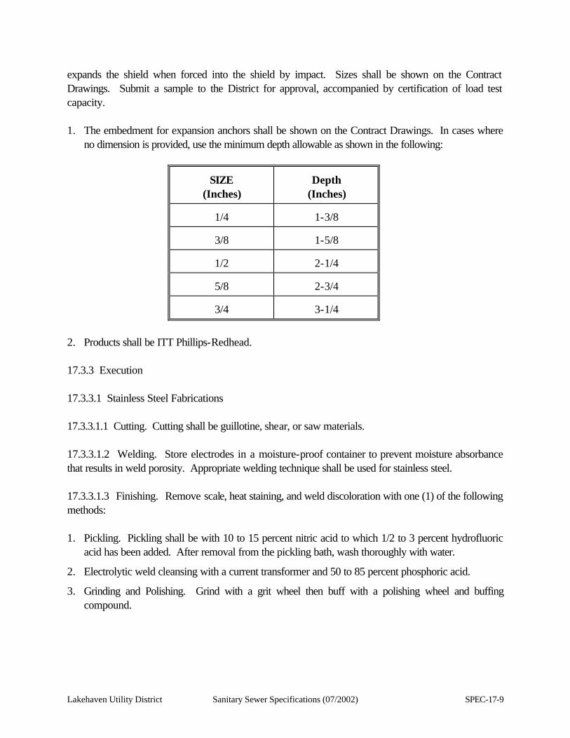
Lakehaven Utility District Sanitary Sewer Specifications (07/2002) SPEC-17-9
expands the shield when forced into the shield by impact. Sizes shall be shown on the Contract Drawings. Submit a sample to the District for approval, accompanied by certification of load test capacity. 1. The embedment for expansion anchors shall be shown on the Contract Drawings. In cases where
no dimension is provided, use the minimum depth allowable as shown in the following:
SIZE
(Inches)
Depth
(Inches)
1/4
1-3/8
3/8
1-5/8
1/2
2-1/4
5/8
2-3/4
3/4
3-1/4
2. Products shall be ITT Phillips-Redhead. 17.3.3 Execution 17.3.3.1 Stainless Steel Fabrications 17.3.3.1.1 Cutting. Cutting shall be guillotine, shear, or saw materials. 17.3.3.1.2 Welding. Store electrodes in a moisture-proof container to prevent moisture absorbance that results in weld porosity. Appropriate welding technique shall be used for stainless steel. 17.3.3.1.3 Finishing. Remove scale, heat staining, and weld discoloration with one (1) of the following methods: 1. Pickling. Pickling shall be with 10 to 15 percent nitric acid to which 1/2 to 3 percent hydrofluoric
acid has been added. After removal from the pickling bath, wash thoroughly with water.
2. Electrolytic weld cleansing with a current transformer and 50 to 85 percent phosphoric acid.
3. Grinding and Polishing. Grind with a grit wheel then buff with a polishing wheel and buffing compound.
SPEC-17-10 Sanitary Sewer Specifications (07/2002) Lakehaven Utility District
17.4 GALVANIZING 17.4.1 General 17.4.1.1 Description. This section sets for the requirements for hot-dip galvanizing of structural steel members, assemblies and metal fabrications. 17.4.1.1.1 Definitions 1. Hot-Dip Galvanizing: The dipping of steel members and assemblies into molten zinc for lasting (or
long-term) corrosion protection. The resultant zinc coating fuses permanently with the base steel material.
2. Passivating: The chemical treatment of freshly galvanized steel materials to prevent humid storage stain (white rust or white corrosion). This treatment (passivation) consists of quenching freshly galvanized steel in water to which a chromate or a chromic-acid solution, or other proprietary solution, has been added.
17.4.1.2 Quality Assurance 17.4.1.2.1 Reference Standards 1. American Hot-Dip Galvanizers Association, Inc. (AHDGA):Publication, "Inspection Manual for
Hot-Dip Galvanized Products."
2. American Society for Testing and Materials (ASTM):
A 120 Pipe, Steel, Black and Hot-Dipped Zinc-Coated (Galvanized) Welded and Seamless, for Ordinary Uses.
A 123 Zinc (Hot-Galvanized) Coatings on Products Fabricated from Rolled, Pressed, and Forged Steel Shapes, Plates, Bars, and Strip.
A 143 Safeguarding Against Embrittlement of Hot-Dip Galvanized Structural Steel Products and Procedure for Detecting Embrittlement.
A 153 Zinc Coating (Hot-Dip) on Iron and Steel Hardware.
A 325 High Strength Bolts for Structural Steel Joints including suitable nuts and plain hardened washers.
A 384 Safeguarding Against Warpage and Distortion During Hot-Dip Galvanizing of Steel Assemblies.
A 385 Providing High Quality Zinc Coatings (Hot-Dip).
A 386 Zinc Coating (Hot-Dip) on Assembled Steel Products.
A 563 Carbon Steel Nuts.

Lakehaven Utility District Sanitary Sewer Specifications (07/2002) SPEC-17-11
A 780 Repair of Damaged Hot-Dip Galvanized Coatings.
SPEC-17-12 Sanitary Sewer Specifications (07/2002) Lakehaven Utility District
B 6 Zinc (Slab Zinc).
D 2092 Preparation of Zinc-Coated Steel Surfaces for Painting.
17.4.1.2.2 Certification. Furnish Certificates of Compliance with ASTM Specifications, and Standards specified herein. Each certificate to be signed by Contractor and Galvanizer certifying that steel materials, bolts, nuts, washers, and items of iron and steel hardware conform with specified requirements. 17.4.1.2.3 Inspections and Tests. Inspections, tests and samples may be made to determine conformance with ASTM Specifications, and Standards. Inspection rights and privileges, procedures, and acceptance or rejection of galvanized steel materials to conform with ASTM A 123, A 153, or A 386, as applicable. Inspections and tests may include the following: 1. Visual examination of samples and finished products.
2. Tests to determine weight or mass of zinc coating per square foot of metal surface.
3. Test to determine distribution and uniformity of zinc coating. 17.4.1.3 Submittals. Furnish Certificates of Compliance with certified original and two (2) copies. 17.4.1.4 Product Delivery, Storage And Handling 17.4.1.4.1 Packaging. Packaging shall be of a type to prevent damage to galvanized surfaces and distortion of steel materials and components. 17.4.1.4.2 Handling and Storage. Handle and protect galvanized materials from damage to zinc coating. To avoid humid storage stain, space surfaces of galvanized materials to permit free circulation of air. 17.4.1.4.3 Damaged Material. Repair material showing evidence of damage to zinc coating. If not repairable, material with damaged coating will be subject to rejection. 17.4.2 Products 17.4.2.1 Steel Materials. Material for galvanizing shall be geometrically suitable for galvanizing as specified in ASTM A 384 and A 385. Steel materials suitable include structural shapes, pipe, sheet, fabrications, and assemblies. Material shall be chemically suitable for galvanizing. 17.4.2.2 Iron And Steel Hardware. Bolts, nuts, washers, and items of iron and steel hardware furnished for galvanizing shall be suitable for hot-dip galvanizing. Inspect iron and steel hardware before galvanizing and ascertain whether suitable for galvanizing. Replace items that are not suitable for galvanizing.
Lakehaven Utility District Sanitary Sewer Specifications (07/2002) SPEC-17-13
17.4.2.3 Zinc For Galvanizing. Zinc for galvanizing shall conform with ASTM B 6, as specified in ASTM A 123. 17.4.2.4 Galvanizing 17.4.2.4.1 Steel members, fabrications, and assemblies to be galvanized after fabrication, shall be by hot-dip process in accordance with ASTM A 123 or A 386, as applicable. Weight of zinc coating to conform to requirements specified under "Weight of Coating" in ASTM A 123 or ASTM A 386, as applicable. 17.4.2.4.2 Safeguard against steel embrittlement in conformance with ASTM A 143. 17.4.2.4.3 Safeguard against warpage or distortion of steel members to conform with ASTM A 384. Notify Engineer of potential warpage problems that may require modification in design, before proceeding with steel fabrications. 17.4.2.4.4 Finish and uniformity of zinc coating and adherence of coating to conform with ASTM A 123, A 153, or A 386, as applicable. 17.4.2.4.5 Bolts, nuts, washers, and iron and steel hardware components shall be galvanized in accordance with ASTM A 153. Weight of zinc coating shall conform to requirements specified under "Weight of Coating" in ASTM A 153. Nuts to be tapped after galvanizing shall conform to minimum diametrical amounts as specified in ASTM A 563. Coat nuts with water proof lubricant, clean and dry to touch. High strength bolts for structural steel joints shall be galvanized in accordance with ASTM A 325. 17.4.3 Execution 17.4.3.1 Installation Of Steel Materials. Steel materials, fabrications, and assemblies are specified to be installed in various other sections of these Specifications and according to the Contract Drawing. 17.4.3.2 Field Inspection. Inspect installed galvanized materials, fabrications, and assemblies to conform with applicable requirements of ADHGA "Inspection Manual for Hot-Dip Galvanized Products," consisting of visual inspections. 17.5 PLASTIC FABRICATIONS 17.5.1 General 17.5.1.1 Description. This section covers furnishing, installing and erecting materials required to provide the necessary plastic fabrications as shown on the Contract Drawings and as specified herein.
SPEC-17-14 Sanitary Sewer Specifications (07/2002) Lakehaven Utility District
17.5.1.2 Submittals. Submit the following to the District for approval even though items proposed to be furnished conform to the exact descriptions stated in this section or shown on the Contract Drawings. 1. Manufacturer's descriptive details and/or samples of the manufacturer's standard product which is
proposed for the project.
2. Provide submittals to the District sufficiently in advance of the start of work to allow time for approval by the District without delaying the work.
17.5.2 Products 17.5.2.1 General. Provide materials and fabricated items from an established and reputable manufacturer. Supply only new materials made from first quality ingredients and guaranteed to perform the required service. 17.5.3 Execution 17.5.3.1 Installation. All connections and support details shall be as shown on the Contract Drawings or as required by the manufacturer. 17.5.3.2 Testing. Provide all labor and materials to demonstrate compliance with the load capacity specified in Section 17.5.2.2.3 of these Specifications to the District's satisfaction. 17.6 SPECIALTIES 17.6.1 General 17.6.1.1 Description. This section covers furnishing and installing the below listed specialty items at the pump station site. 17.6.1.2 Submittals. Submit the following to the District for approval, even though items proposed to be furnished conform to the exact description stated in this section, or on the Contract Drawings. 1. Manufacturer's descriptive details of the manufacturer's latest standard product which is proposed
for this project.
2. Submittal to the District sufficiently in advance of the start of the work to allow time for approval by the District without delaying the work.
Lakehaven Utility District Sanitary Sewer Specifications (07/2002) SPEC-17-15
17.6.2 Products 17.6.2.1 First Aid Kit 17.6.2.1.1 First Aid Cabinet. Provide first aid kits having the following items: 16-Package Kit 2 pkg. adhesive bandage, 3/4" (16 per pkg.) 1 pkg. antiseptic soap or pads (5 per pkg.) 2 pkg. bandage compress 4" (1 per pkg.) 1 pkg. burn ointment, (6 tubes per pkg.) 2 pkg. triangular bandage, 40" (1 per pkg.) 1 pkg. scissors and tweezers, (1 each per pkg.) 1 pkg. adhesive tape, 1/2" x 2-1/2 yards 3 pkg. absorbent gauze, 24" x 72" (1 per pkg.) 1 pkg. roller bandage, 2" x 6 yards 2 pkg. sting kill swabs, (10 per unit) One (1) per station shall be tagged and mounted inside the electrical control panel. 17.6.2.2 Goggles. Goggles shall be tight-fitting, non-ventilated for protection against dust and chemical splash hazards, large enough to wear over prescription glasses and meeting Federal Specification GG-G-53113. The manufacturer shall be Encon Model #01-4000-67. Provide two (2) per station to be installed in a dust proof cabinet along with the ear muffs (17.6.2.3) located inside the electrical control panel. 17.6.2.3 Ear Muffs. Ear muffs shall be for protection against loud noise, meeting OSHA requirements. Manufacturer shall be Wilson Model 358A. Provide two (2) sets of ear muffs per station to be installed in a dust proof cabinet located within the electrical control panel. 17.6.2.4 Fire Extinguishers. Each fire extinguisher shall be Kidder 6 lb. #2A40BL and shall be listed by Underwriters Laboratories. Provide one (1) fire extinguisher per station mounted within the electrical control panel.
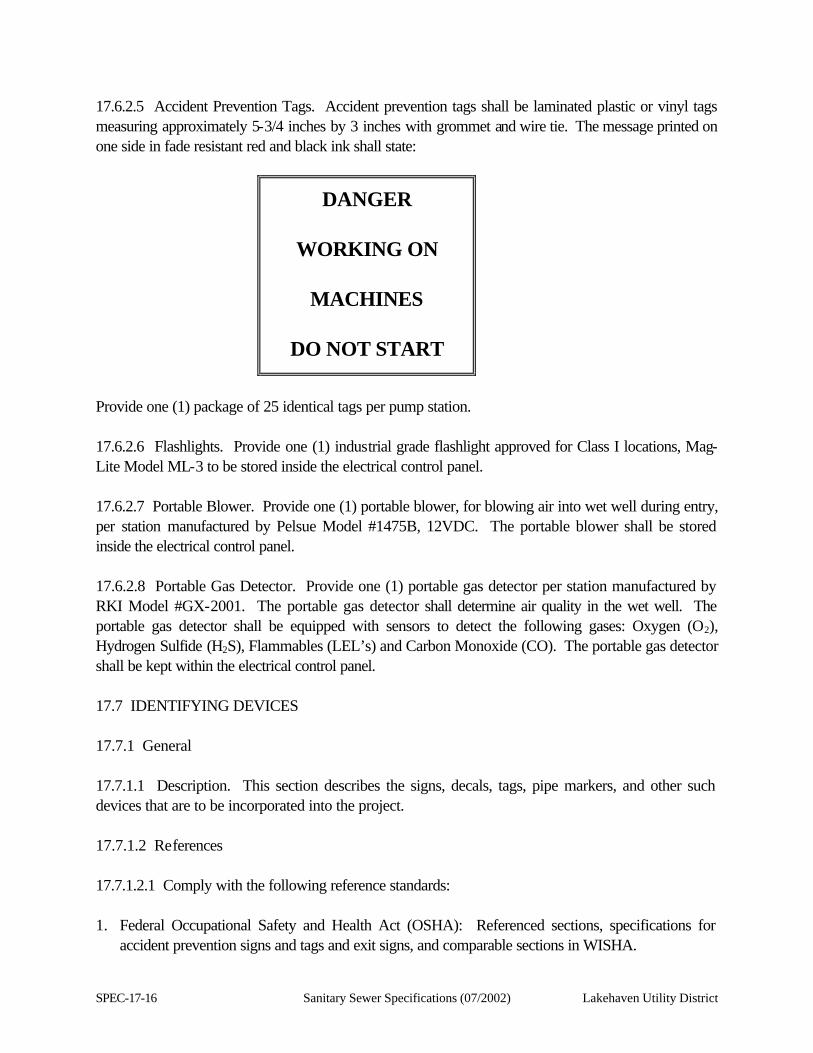
SPEC-17-16 Sanitary Sewer Specifications (07/2002) Lakehaven Utility District
17.6.2.5 Accident Prevention Tags. Accident prevention tags shall be laminated plastic or vinyl tags measuring approximately 5-3/4 inches by 3 inches with grommet and wire tie. The message printed on one side in fade resistant red and black ink shall state:
DANGER
WORKING ON
MACHINES
DO NOT START
Provide one (1) package of 25 identical tags per pump station. 17.6.2.6 Flashlights. Provide one (1) industrial grade flashlight approved for Class I locations, Mag-Lite Model ML-3 to be stored inside the electrical control panel. 17.6.2.7 Portable Blower. Provide one (1) portable blower, for blowing air into wet well during entry, per station manufactured by Pelsue Model #1475B, 12VDC. The portable blower shall be stored inside the electrical control panel. 17.6.2.8 Portable Gas Detector. Provide one (1) portable gas detector per station manufactured by RKI Model #GX-2001. The portable gas detector shall determine air quality in the wet well. The portable gas detector shall be equipped with sensors to detect the following gases: Oxygen (O2), Hydrogen Sulfide (H2S), Flammables (LEL’s) and Carbon Monoxide (CO). The portable gas detector shall be kept within the electrical control panel. 17.7 IDENTIFYING DEVICES 17.7.1 General 17.7.1.1 Description. This section describes the signs, decals, tags, pipe markers, and other such devices that are to be incorporated into the project. 17.7.1.2 References 17.7.1.2.1 Comply with the following reference standards: 1. Federal Occupational Safety and Health Act (OSHA): Referenced sections, specifications for
accident prevention signs and tags and exit signs, and comparable sections in WISHA.
Lakehaven Utility District Sanitary Sewer Specifications (07/2002) SPEC-17-17
2. Sign Division of the Porcelain Enamel Institute: PEI:S-103, recommended standards for porcelain enamel signs.
3. American National Standard Specifications, ANSI A13.1, "Scheme for the Identification of Piping Systems."
4. National Fire Protection Association (NFPA) No. 704, System for the identification of the fire hazards and materials.
17.7.1.2.2 Comply with the manufacturer's published recommendation for installation of the materials used. 17.7.1.3 Submittals 17.7.1.3.1 Submit scaled drawings of every custom made sign proposed for use, showing size of lettering and colors. 17.7.1.3.2 Submit manufacturer's standard color palette for selection where requested herein. 17.7.1.3.3 Submit product literature on items proposed to be furnished. 17.7.2 Products 17.7.2.1 Signs. Provide signs by W. H. Brady Co., Seton Name Plate Co., or equal as approved by Lakehaven Utility District. 17.7.2.1.1 Sign Number 1: FIRE EQUIPMENT LOCATION MARKERS 1. Size: 4 inches wide by 18 inches (approximate size).
2. Material: Vinyl with adhesive back.
3. Text: Bright, fade resistant red on white downward facing directional arrow on red field. Text as shown on schedule below.
Sign #
Sign Text
1
FIRE EXTINGUISHER
17.7.2.1.2 Sign Numbers 2 through 4: Caution Signs 1. Size: 14 inches wide by 10 inches high.
SPEC-17-18 Sanitary Sewer Specifications (07/2002) Lakehaven Utility District
2. Material: Porcelain Enamel, 18 gauge.
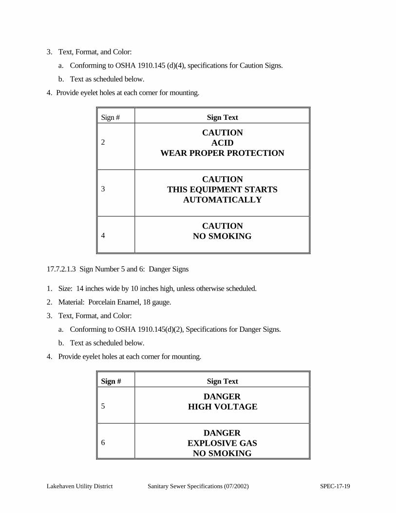
Lakehaven Utility District Sanitary Sewer Specifications (07/2002) SPEC-17-19
3. Text, Format, and Color:
a. Conforming to OSHA 1910.145 (d)(4), specifications for Caution Signs.
b. Text as scheduled below.
4. Provide eyelet holes at each corner for mounting.
Sign #
Sign Text
2
CAUTION
ACID WEAR PROPER PROTECTION
3
CAUTION
THIS EQUIPMENT STARTS AUTOMATICALLY
4
CAUTION
NO SMOKING
17.7.2.1.3 Sign Number 5 and 6: Danger Signs 1. Size: 14 inches wide by 10 inches high, unless otherwise scheduled.
2. Material: Porcelain Enamel, 18 gauge.
3. Text, Format, and Color:
a. Conforming to OSHA 1910.145(d)(2), Specifications for Danger Signs.
b. Text as scheduled below.
4. Provide eyelet holes at each corner for mounting.
Sign #
Sign Text
5
DANGER
HIGH VOLTAGE
6
DANGER
EXPLOSIVE GAS NO SMOKING

SPEC-17-20 Sanitary Sewer Specifications (07/2002) Lakehaven Utility District
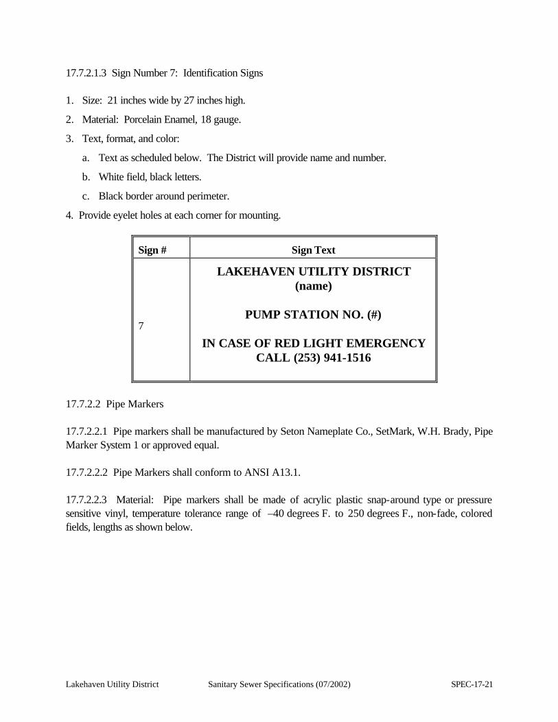
Lakehaven Utility District Sanitary Sewer Specifications (07/2002) SPEC-17-21
17.7.2.1.3 Sign Number 7: Identification Signs 1. Size: 21 inches wide by 27 inches high.
2. Material: Porcelain Enamel, 18 gauge.
3. Text, format, and color:
a. Text as scheduled below. The District will provide name and number.
b. White field, black letters.
c. Black border around perimeter.
4. Provide eyelet holes at each corner for mounting.
Sign #
Sign Text
7
LAKEHAVEN UTILITY DISTRICT
(name)
PUMP STATION NO. (#)
IN CASE OF RED LIGHT EMERGENCY CALL (253) 941-1516
17.7.2.2 Pipe Markers 17.7.2.2.1 Pipe markers shall be manufactured by Seton Nameplate Co., SetMark, W.H. Brady, Pipe Marker System 1 or approved equal. 17.7.2.2.2 Pipe Markers shall conform to ANSI A13.1. 17.7.2.2.3 Material: Pipe markers shall be made of acrylic plastic snap-around type or pressure sensitive vinyl, temperature tolerance range of –40 degrees F. to 250 degrees F., non-fade, colored fields, lengths as shown below.
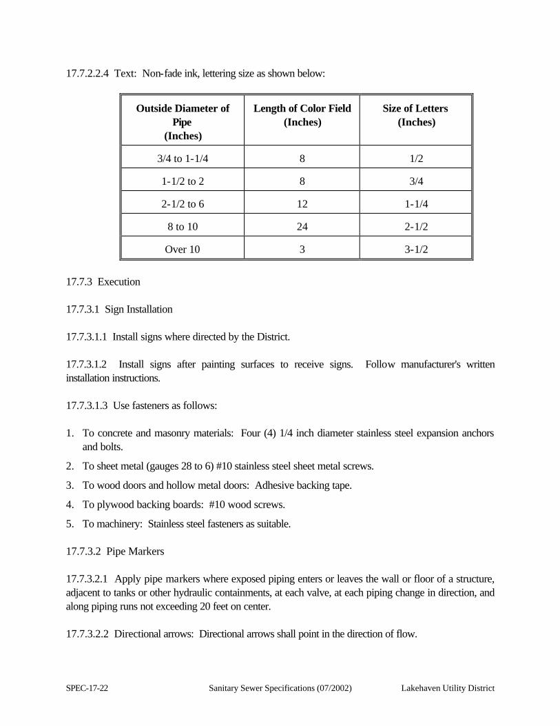
SPEC-17-22 Sanitary Sewer Specifications (07/2002) Lakehaven Utility District
17.7.2.2.4 Text: Non-fade ink, lettering size as shown below:
Outside Diameter of
Pipe (Inches)
Length of Color Field
(Inches)
Size of Letters
(Inches)
3/4 to 1-1/4
8
1/2
1-1/2 to 2
8
3/4
2-1/2 to 6
12
1-1/4
8 to 10
24
2-1/2
Over 10
3
3-1/2
17.7.3 Execution 17.7.3.1 Sign Installation 17.7.3.1.1 Install signs where directed by the District. 17.7.3.1.2 Install signs after painting surfaces to receive signs. Follow manufacturer's written installation instructions. 17.7.3.1.3 Use fasteners as follows: 1. To concrete and masonry materials: Four (4) 1/4 inch diameter stainless steel expansion anchors
and bolts.
2. To sheet metal (gauges 28 to 6) #10 stainless steel sheet metal screws.
3. To wood doors and hollow metal doors: Adhesive backing tape.
4. To plywood backing boards: #10 wood screws.
5. To machinery: Stainless steel fasteners as suitable. 17.7.3.2 Pipe Markers 17.7.3.2.1 Apply pipe markers where exposed piping enters or leaves the wall or floor of a structure, adjacent to tanks or other hydraulic containments, at each valve, at each piping change in direction, and along piping runs not exceeding 20 feet on center. 17.7.3.2.2 Directional arrows: Directional arrows shall point in the direction of flow.
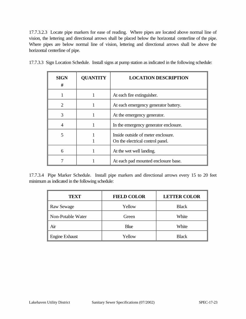
Lakehaven Utility District Sanitary Sewer Specifications (07/2002) SPEC-17-23
17.7.3.2.3 Locate pipe markers for ease of reading. Where pipes are located above normal line of vision, the lettering and directional arrows shall be placed below the horizontal centerline of the pipe. Where pipes are below normal line of vision, lettering and directional arrows shall be above the horizontal centerline of pipe. 17.7.3.3 Sign Location Schedule. Install signs at pump station as indicated in the following schedule:
SIGN
#
QUANTITY
LOCATION DESCRIPTION
1
1
At each fire extinguisher.
2
1
At each emergency generator battery.
3
1
At the emergency generator.
4
1
In the emergency generator enclosure.
5
1 1
Inside outside of meter enclosure. On the electrical control panel.
6
1
At the wet well landing.
7
1
At each pad mounted enclosure base.
17.7.3.4 Pipe Marker Schedule. Install pipe markers and directional arrows every 15 to 20 feet minimum as indicated in the following schedule:
TEXT
FIELD COLOR
LETTER COLOR
Raw Sewage
Yellow
Black
Non-Potable Water
Green
White
Air
Blue
White
Engine Exhaust
Yellow
Black
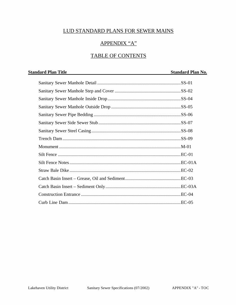
LUD STANDARD PLANS FOR SEWER MAINS
APPENDIX “A”
TABLE OF CONTENTS
Standard Plan Title Standard Plan No.
Sanitary Sewer Manhole Detail ........................................................................SS-01
Sanitary Sewer Manhole Step and Cover .........................................................SS-02
Sanitary Sewer Manhole Inside Drop ...............................................................SS-04
Sanitary Sewer Manhole Outside Drop ............................................................SS-05
Sanitary Sewer Pipe Bedding ...........................................................................SS-06
Sanitary Sewer Side Sewer Stub .......................................................................SS-07
Sanitary Sewer Steel Casing .............................................................................SS-08
Trench Dam......................................................................................................SS-09
Monument .........................................................................................................M-01
Silt Fence ..........................................................................................................EC-01
Silt Fence Notes ................................................................................................EC-01A
Straw Bale Dike ................................................................................................EC-02
Catch Basin Insert – Grease, Oil and Sediment................................................EC-03
Catch Basin Insert – Sediment Only.................................................................EC-03A
Construction Entrance ......................................................................................EC-04
Curb Line Dam.................................................................................................EC-05
Lakehaven Utility District Sanitary Sewer Specifications (07/2002) APPENDIX "A" - TOC
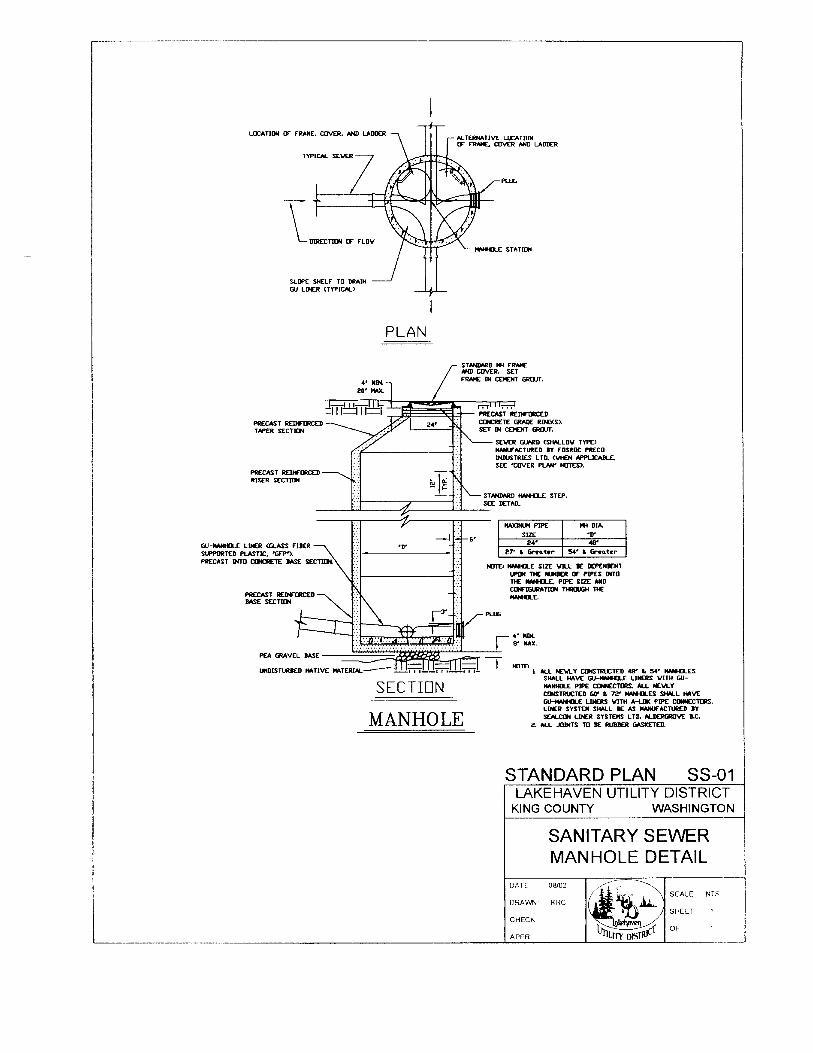
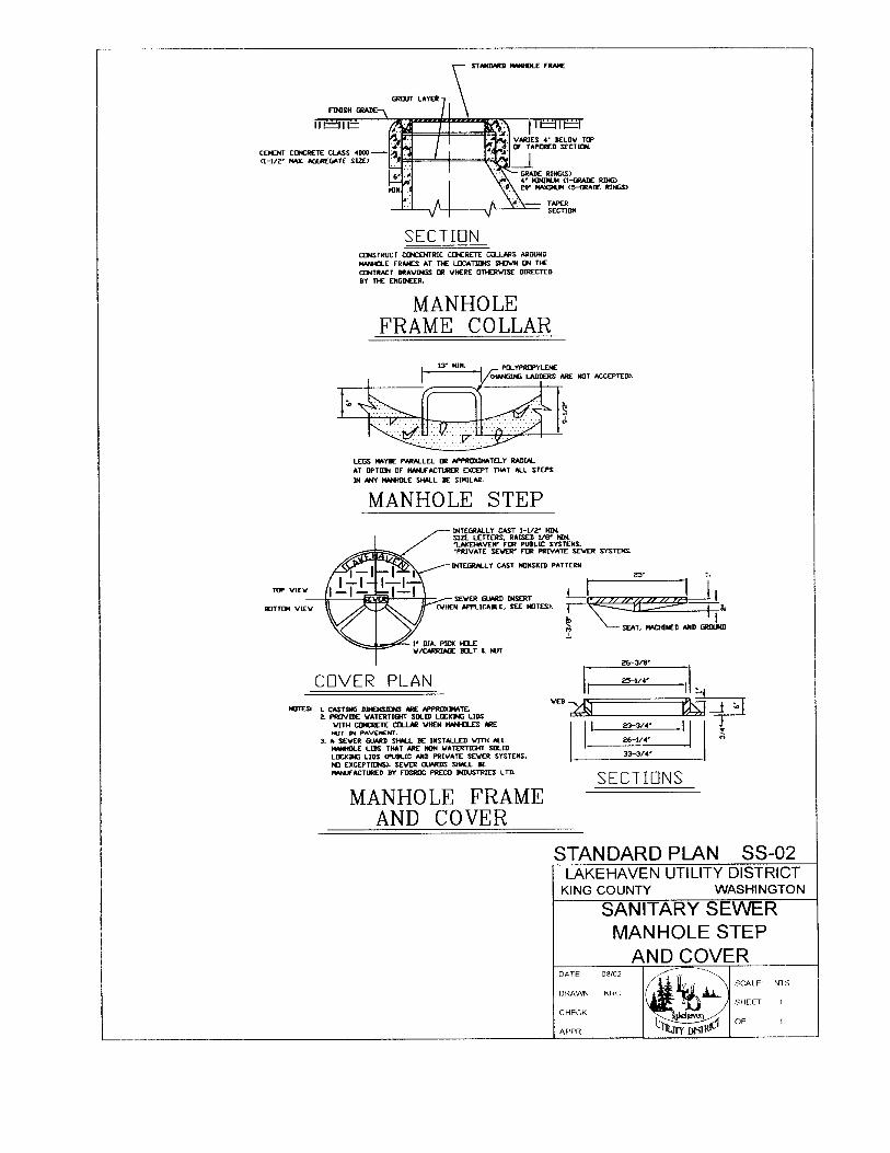
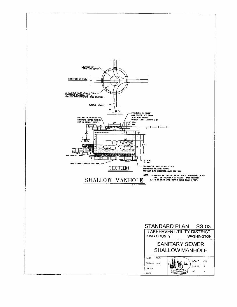
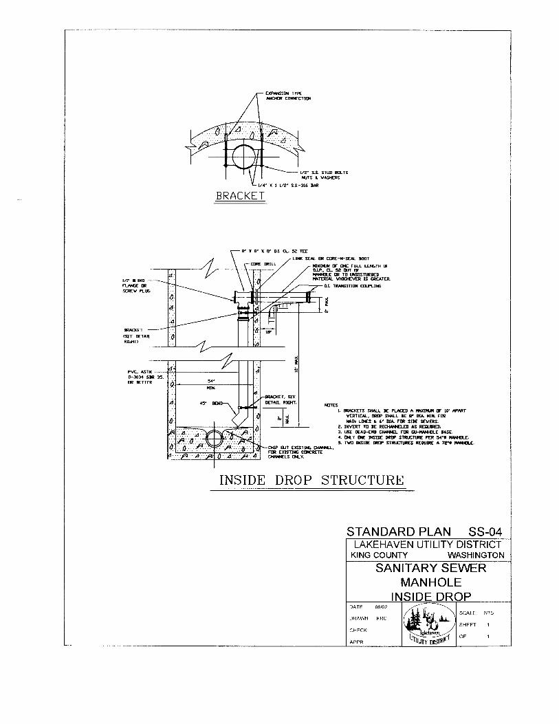
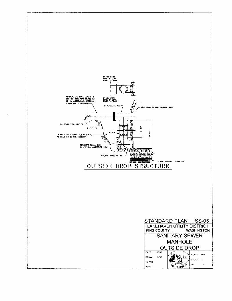
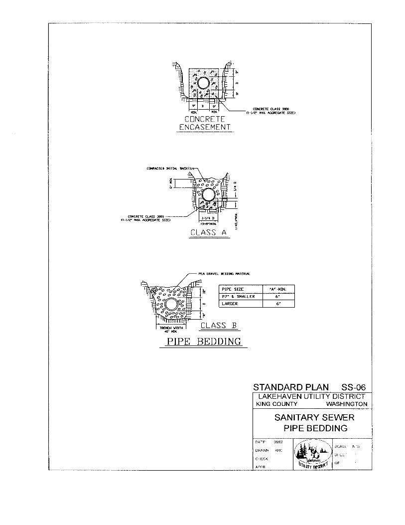
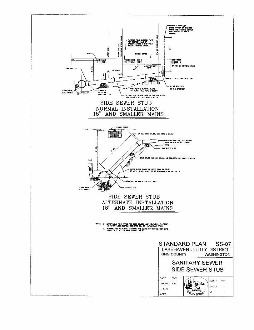
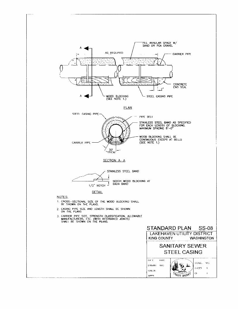
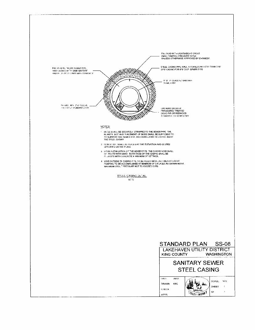
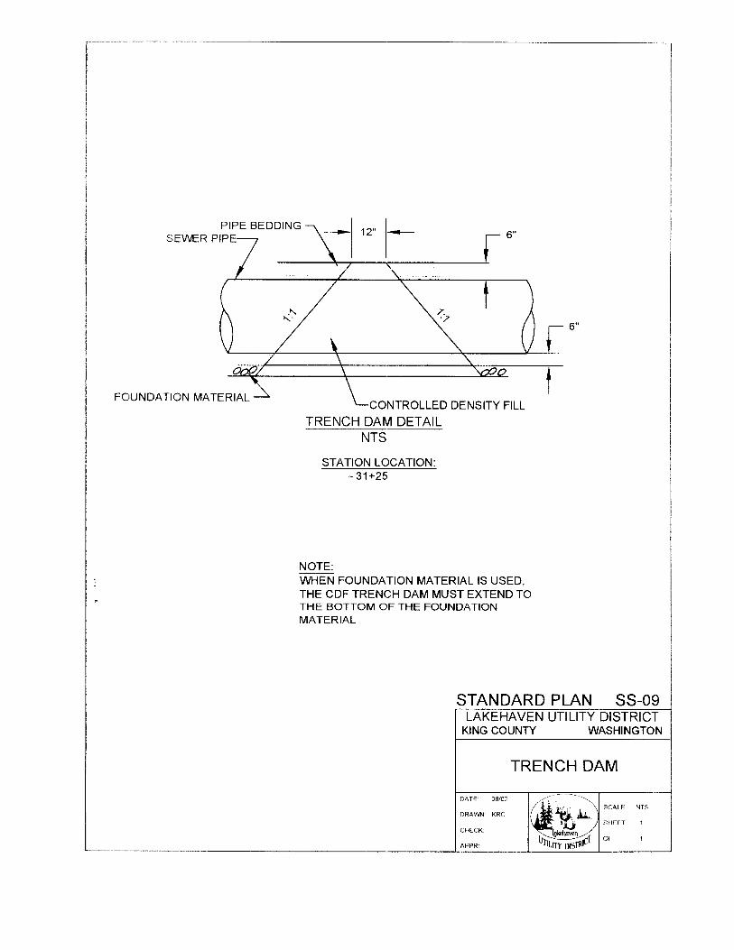
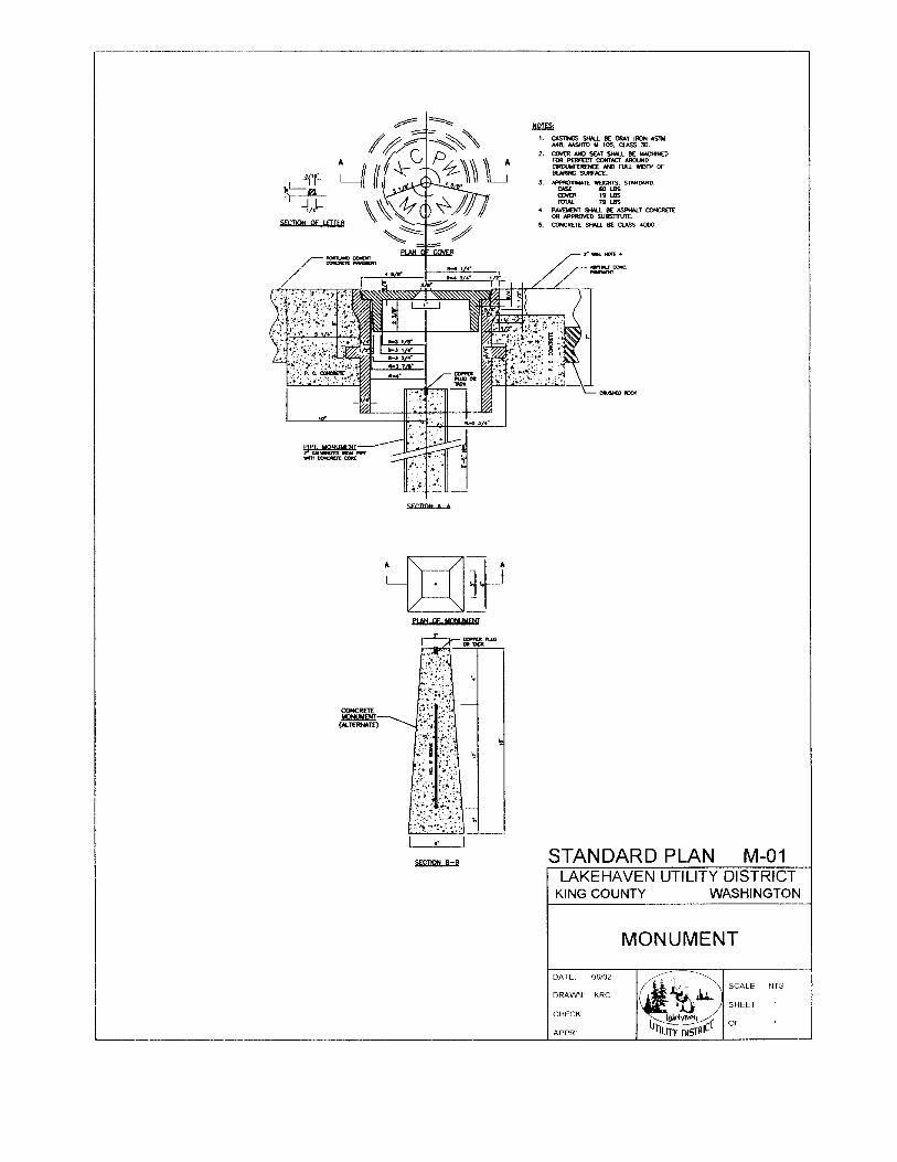
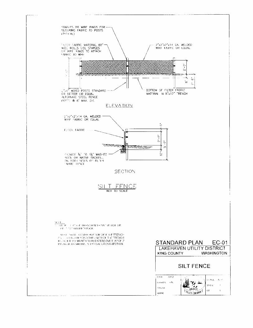
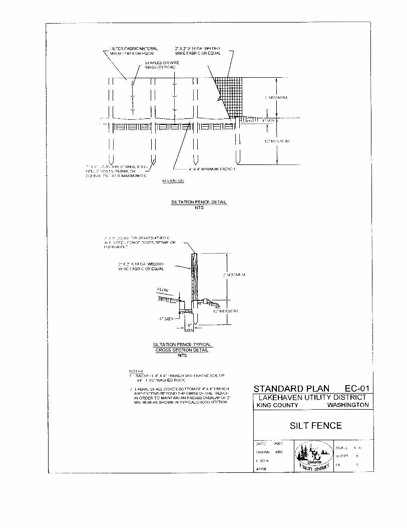
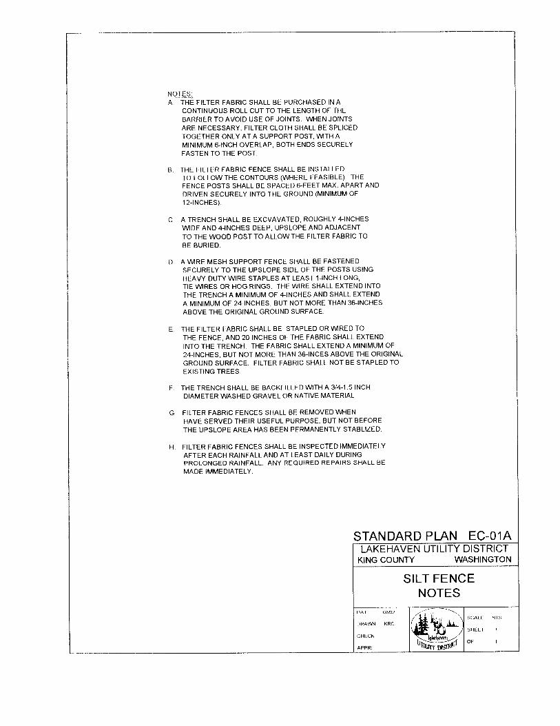
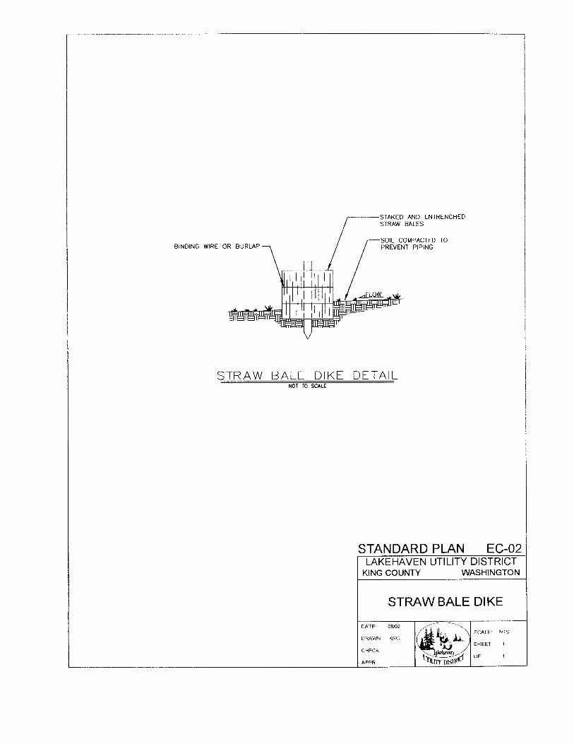
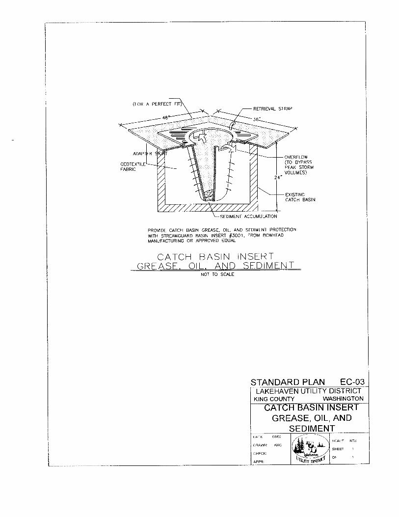
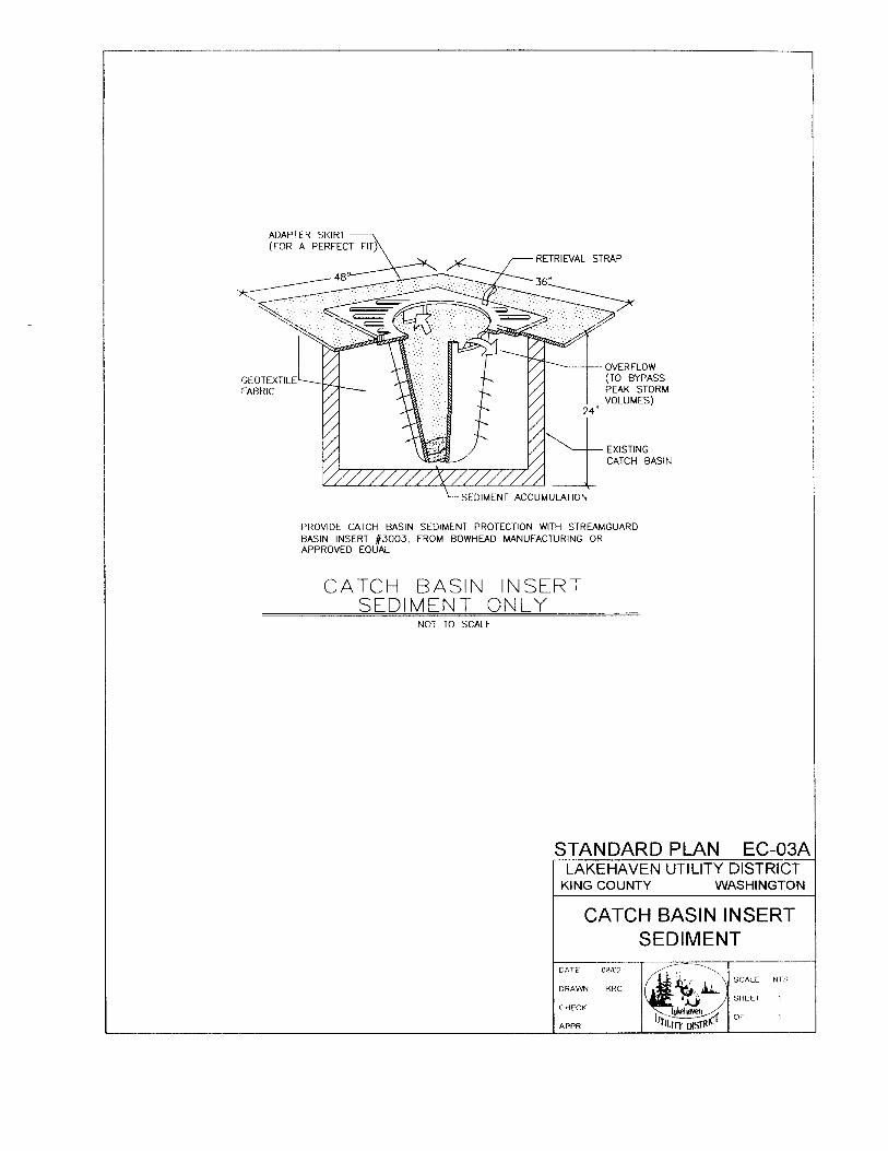
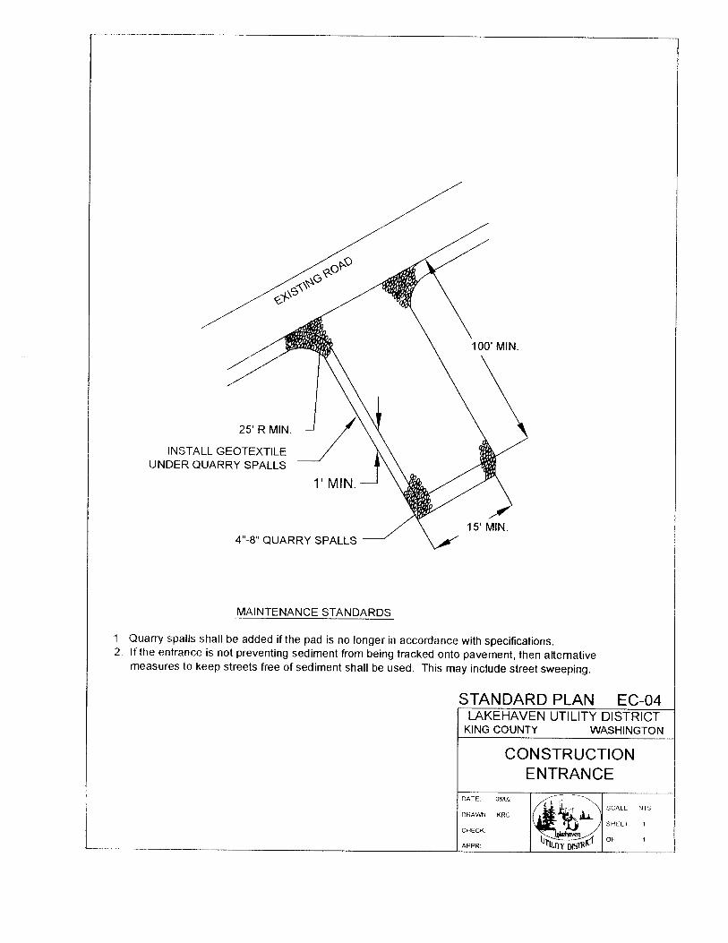
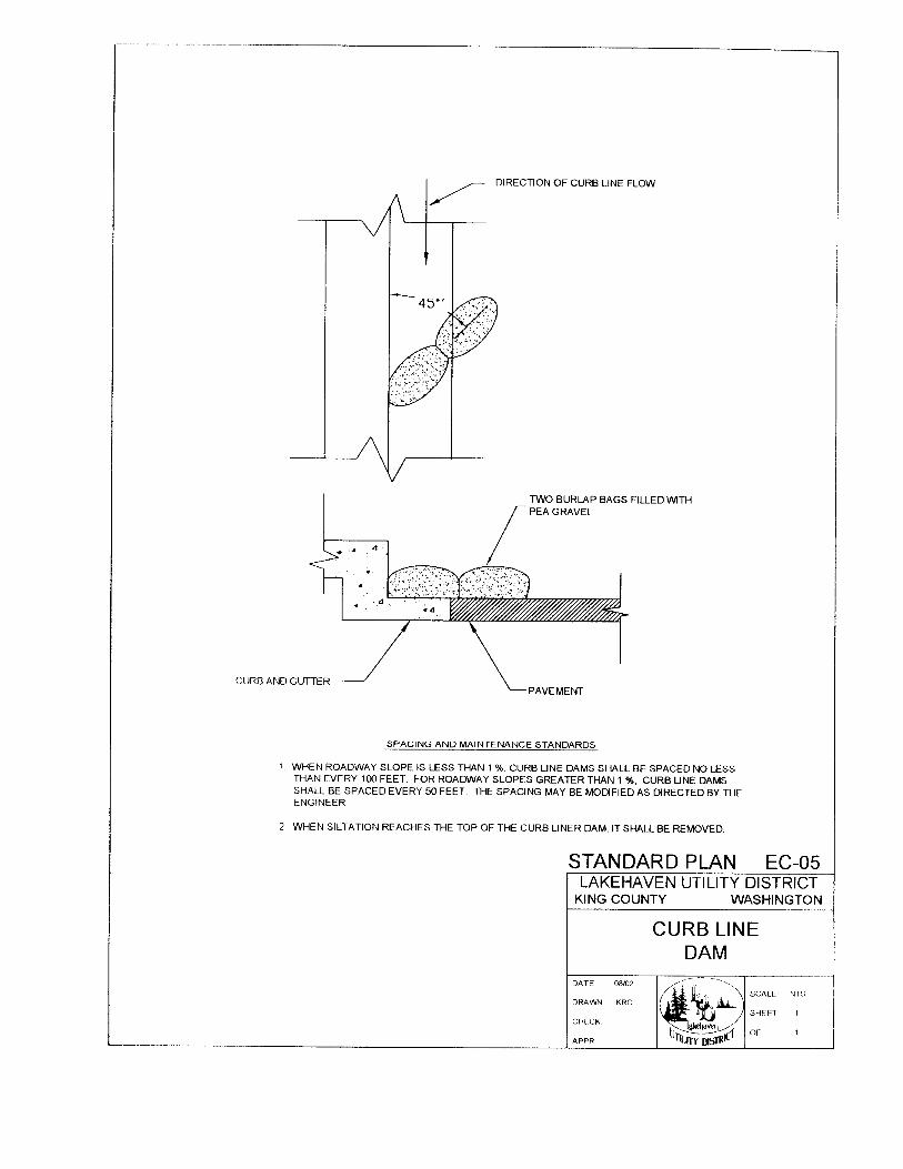
LUD STANDARD PLANS FOR SIDE SEWERS
APPENDIX “B”
TABLE OF CONTENTS
Standard Plan Title Standard Plan No.
Typical Building Sewer Installation.................................................................SSS-01
Typical Building Sewer Installation.................................................................SSS-02
Typical Side Sewer Site Layout .......................................................................SSS-03
Lakehaven Utility District Sanitary Sewer Specifications (07/2002) APPENDIX "B" – TOC
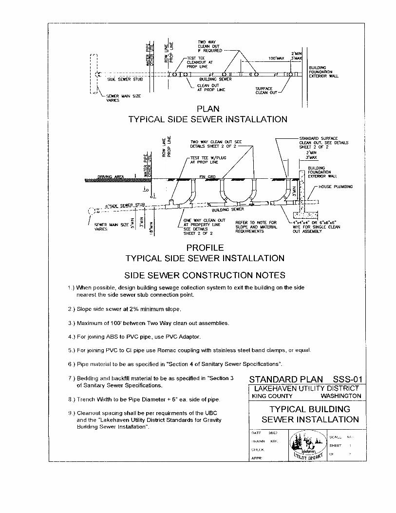
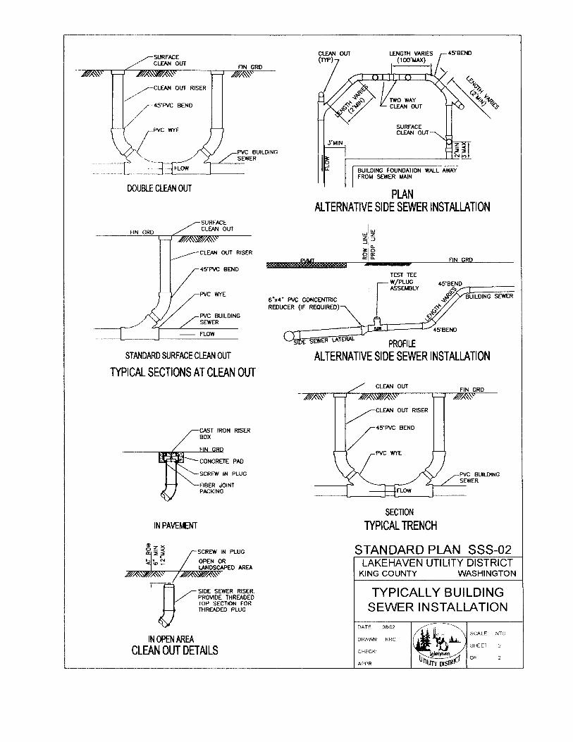
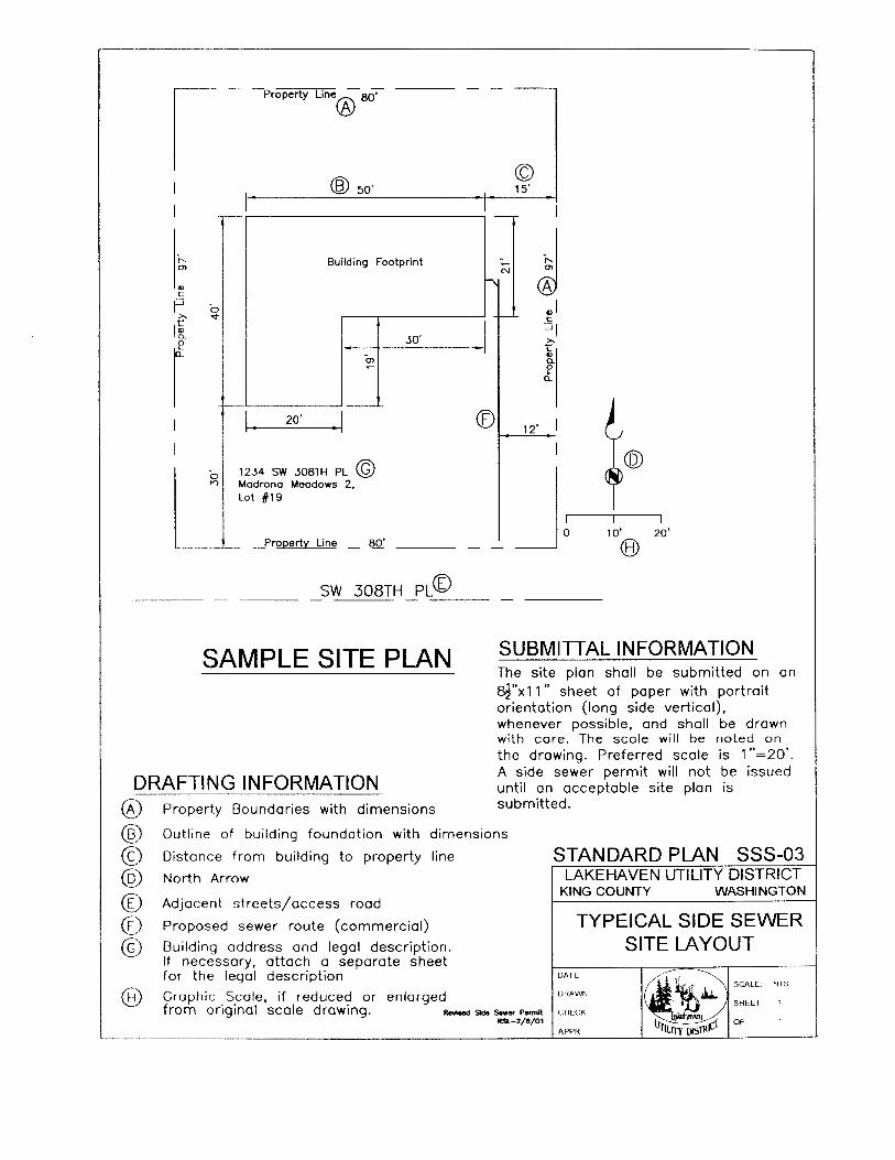

LUD STANDARD PLANS FOR PUMP STATIONS
APPENDIX “E”
TABLE OF CONTENTS
Standard Plan Title Standard Plan No.
Site Plan............................................................................................................P-01
Plan View..........................................................................................................P-02
Profile View......................................................................................................P-03
Electrical Plans .................................................................................................E-01-11
Sewer Force Main Emergency Connection Facility.........................................PS-01
Vault/Pump Station Ladder ..............................................................................PS-02
Lakehaven Utility District Sanitary Sewer Specifications (07/2002) APPENDIX "E" – TOC