Embed Size (px)
Citation preview
TECHNOLOGY TO THE FORE
SF6-GAS CIRCUIT BREAKERSFOR OUT-DOOR USE (72.5 kV TO 420 kV)SWITCHGEAR
C O M P L E X
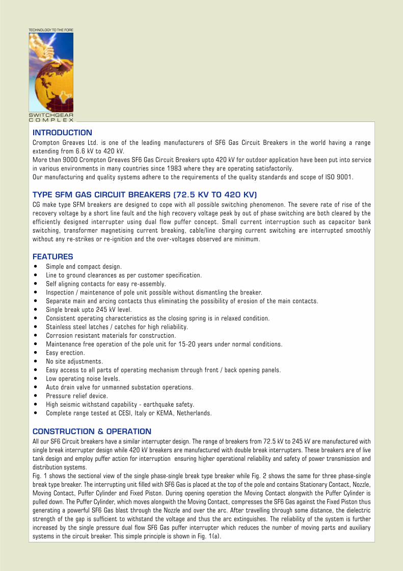
INTRODUCTIONCrompton Greaves Ltd. is one of the leading manufacturers of SF6 Gas Circuit Breakers in the world having a rangeextending from 6.6 kV to 420 kV.More than 9000 Crompton Greaves SF6 Gas Circuit Breakers upto 420 kV for outdoor application have been put into servicein various environments in many countries since 1983 where they are operating satisfactorily.Our manufacturing and quality systems adhere to the requirements of the quality standards and scope of ISO 9001.
TYPE SFM GAS CIRCUIT BREAKERS (72.5 KV TO 420 KV)CG make type SFM breakers are designed to cope with all possible switching phenomenon. The severe rate of rise of therecovery voltage by a short line fault and the high recovery voltage peak by out of phase switching are both cleared by theefficiently designed interrupter using dual f low puffer concept. Small current interruption such as capacitor bankswitching, transformer magnetising current breaking, cable/line charging current switching are interrupted smoothlywithout any re-strikes or re-ignition and the over-voltages observed are minimum.
FEATURES• Simple and compact design.• Line to ground clearances as per customer specification.• Self aligning contacts for easy re-assembly.• Inspection / maintenance of pole unit possible without dismantling the breaker.• Separate main and arcing contacts thus eliminating the possibility of erosion of the main contacts.• Single break upto 245 kV level.• Consistent operating characteristics as the closing spring is in relaxed condition.• Stainless steel latches / catches for high reliability.• Corrosion resistant materials for construction.• Maintenance free operation of the pole unit for 15-20 years under normal conditions.• Easy erection.• No site adjustments.• Easy access to all parts of operating mechanism through front / back opening panels.• Low operating noise levels.• Auto drain valve for unmanned substation operations.• Pressure relief device.• High seismic withstand capability - earthquake safety.• Complete range tested at CESI, Italy or KEMA, Netherlands.
TECHNOLOGY TO THE FORE
SWITCHGEARC O M P L E X
CONSTRUCTION & OPERATIONAll our SF6 Circuit breakers have a similar interrupter design. The range of breakers from 72.5 kV to 245 kV are manufactured withsingle break interrupter design while 420 kV breakers are manufactured with double break interrupters. These breakers are of livetank design and employ puffer action for interruption ensuring higher operational reliability and safety of power transmission anddistribution systems.Fig. 1 shows the sectional view of the single phase-single break type breaker while Fig. 2 shows the same for three phase-singlebreak type breaker. The interrupting unit filled with SF6 Gas is placed at the top of the pole and contains Stationary Contact, Nozzle,Moving Contact, Puffer Cylinder and Fixed Piston. During opening operation the Moving Contact alongwith the Puffer Cylinder ispulled down. The Puffer Cylinder, which moves alongwith the Moving Contact, compresses the SF6 Gas against the Fixed Piston thusgenerating a powerful SF6 Gas blast through the Nozzle and over the arc. After travelling through some distance, the dielectricstrength of the gap is sufficient to withstand the voltage and thus the arc extinguishes. The reliability of the system is furtherincreased by the single pressure dual flow SF6 Gas puffer interrupter which reduces the number of moving parts and auxiliarysystems in the circuit breaker. This simple principle is shown in Fig. 1(a).
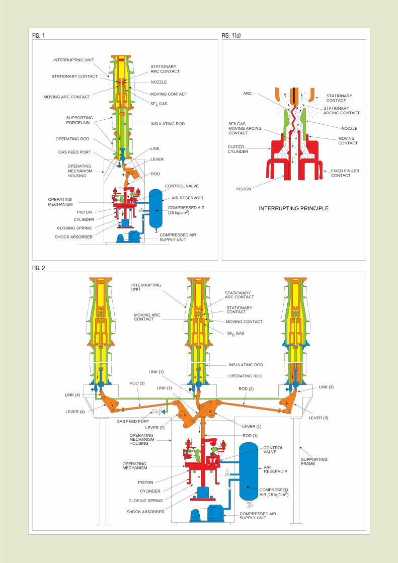
FIG. 1
INTERRUPTING PRINCIPLE
FIG. 2
FIG. 1(a)
PISTON
PUFFERCYLINDER
SF6 GASMOVING ARCINGCONTACT
ARC STATIONARYCONTACT
NOZZLE
MOVINGCONTACT
FIXED FINGERCONTACT
STATIONARYARCING CONTACT
PISTON
INTERRUPTING UNIT
STATIONARY CONTACT
MOVING ARC CONTACT
SUPPORTINGPORCELAIN
OPERATING ROD
GAS FEED PORT
CLOSING SPRING
CYLINDER
SHOCK ABSORBER
AIR RESERVOIR
CONTROL VALVE
ROD
OPERATINGMECHANISM
OPERATINGMECHANISMHOUSING
LEVER
COMPRESSED AIR(15 kg/cm2)
COMPRESSED AIRSUPPLY UNIT
LINK
INSULATING ROD
MOVING CONTACT
NOZZLE
STATIONARYARC CONTACT
SF6 GAS
MOVING ARCCONTACT
INTERRUPTINGUNIT
STATIONARYARC CONTACT
STATIONARYCONTACT
MOVING CONTACT
SF6 GAS
LINK (1)
ROD (3)LINK (2)
LINK (4)
LEVER (4)
GAS FEED PORT
LEVER (2)
OPERATINGMECHANISMHOUSING
OPERATINGMECHANISM
PISTON
CYLINDER
CLOSING SPRING
SHOCK ABSORBER
LEVER (1)
ROD (1)
CONTROLVALVE
AIRRESERVOIR
COMPRESSEDAIR (15 kg/cm2)
COMPRESSED AIRSUPPLY UNIT
ROD (2)
OPERATING ROD
LINK (3)
LEVER (3)
INSULATING ROD
SUPPORTINGFRAME
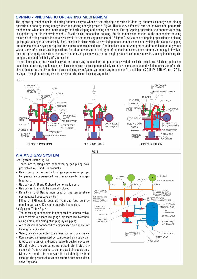
SPRING - PNEUMATIC OPERATING MECHANISMThe operating mechanism is of spring-pneumatic type wherein the tripping operation is done by pneumatic energy and closingoperation is done by spring energy without a spring charging motor (Fig.3). This is very different from the conventional pneumaticmechanisms which use pneumatic energy for both tripping and closing operations. During tripping operation, the pneumatic energyis supplied by an air reservoir which is fitted on the mechanism housing. An air compressor housed in the mechanism housingmaintains the air pressure in the air reservoir at the operating pressure of 15 kg/cm2. At the end of tripping operation the closingspring gets charged automatically. Each breaker is fitted with its own independent compressor thus avoiding the elaborate pipingand compressed air system required for central compressor design. The breakers can be transported and commissioned anywherewithout any infra-structural implications. An added advantage of this type of mechanism is that since pneumatic energy is involvedonly during tripping operation, the entire pneumatic system works on one single pressure and one reservoir, thereby increasing thecompactness and reliability of the breaker.In the single phase autoreclosing type, one operating mechanism per phase is provided in all the breakers. All three poles andassociated operating mechanisms are interconnected electro-pneumatically to ensure simultaneous and reliable operation of all thethree phases. In the three phase autroreclosing type (gang type operating mechanism) - available in 72.5 kV, 145 kV and 170 kVratings - a single operating system drives all the three interrupting units.
FIG. 3
OPENING STAGE OPEN POSITIONCLOSED POSITION
FIG. 4AIR AND GAS SYSTEMGas System (Refer Fig. 4)- Three interrupting units connected by gas piping have
gas valves A, B and C individually.- Gas piping is connected to gas pressure gauge,
temperature compensated gas pressure switch and gasfeed port.
- Gas valves A, B and C should be normally open.- Gas valves D should be normally closed.- Density of SF6 Gas is monitored by gas temperature
compensated pressure switch.- Filling of SF6 gas is possible from gas feed port by
opening gas valve D even in energized condition.Air System (Refer Fig. 4)- The operating mechanism is connected to control valve,
air reservoir, air pressure gauge, air pressure switches,airing nozzle and airing stop plug by air piping.
- Air reservoir is connected to compressed air supply unitthrough check valve.
- Safety valve is connected to air reservoir with drain valve.- Compressed air generated by compressed air supply unit
is led to air reservoir and control valve through check valve.- Check valve prevents compressed a ir ins ide a ir
reservoir from returning to compressed air supply unit.- Moisture inside air reservoir is periodically drained
through the presettable timer actuated automatic drainvalve (optional).
COMPRESSEDAIR (15kg/cm2)
OPERATINGMECHANISM
CONTROL VALVE
GAS FEEDPORT
No. CNo. D
No. B
GAS PIPING
SF6 GAS
No. A
AIR PRESSURE GAUGEAIR PRESSURE SWITCH(FOR ALARM AND LOCK)
AIR PRESSURE SWITCH(FOR COMPRESSOR GOVERNOR)
AIRING NOZZLE
AIRING STOP PLUG
AIRRESERVOIR
DRAIN VALVE
SAFETY VALVE
CHECK VALVE
COMPRESSED AIRSUPPLY UNIT
OPERATINGMECHANISMHOUSING
AIR PIPING
GAS TEMPERATURECOMPENSATEDPRESSURE SWITCH
GAS PRESSUREGAUGE
63G 63AL 63AG
INTERRUPTING UNIT
COMPRESSEDAIR (15 kg/cm2)
STATIONARYCONTACT
MOVING CONTACT
SPRING A
EXHAUSTPORT
ROLLER
PLUNGER
CLOSING COIL
TRIGGER
HOLDING LATCH
AIR RESERVOIR
COMPRESSEDAIR (15 kg/cm2-g)
SHOCKABSORBER
CLOSINGSPRING
CYLINDER
PISTON
PISTON ROD
ANTI-PUMPINGPIN
ANTI-PUMPINGLEVER
STATIONARYCONTACT
MOVINGCONTACT
PIN "A"EXHAUSTPORT
CAM
LEVER
PLUNGER
TRIP COIL
TRIGGER
LATCH
CYLINDRICALVALVE
AIR RESERVOIRCONTROLVALVE COMPRESSRD
AIR (15 kg/cm2)
VALVE SEAT
SHOCK ABSORBERCLOSINGSPRING
CYLINDER
PISTON
PISTONROD
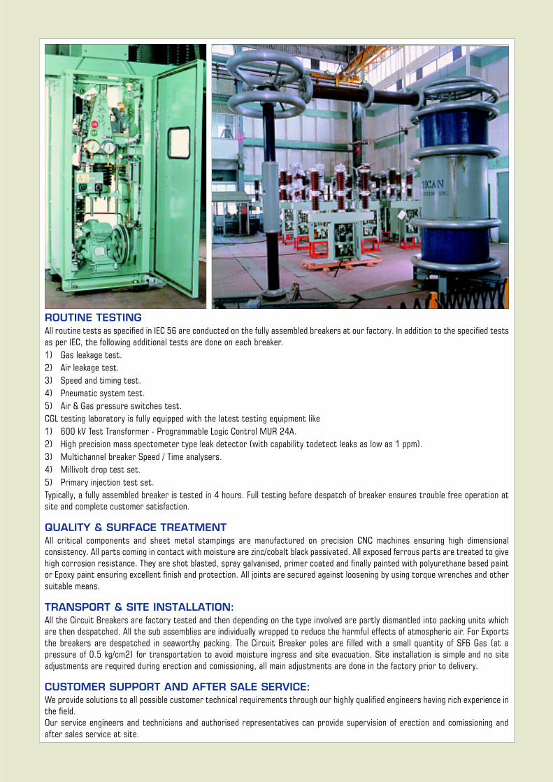
ROUTINE TESTINGAll routine tests as specified in IEC 56 are conducted on the fully assembled breakers at our factory. In addition to the specified testsas per IEC, the following additional tests are done on each breaker.1) Gas leakage test.2) Air leakage test.3) Speed and timing test.4) Pneumatic system test.5) Air & Gas pressure switches test.CGL testing laboratory is fully equipped with the latest testing equipment like1) 600 kV Test Transformer - Programmable Logic Control MUR 24A.2) High precision mass spectometer type leak detector (with capability todetect leaks as low as 1 ppm).3) Multichannel breaker Speed / Time analysers.4) Millivolt drop test set.5) Primary injection test set.Typically, a fully assembled breaker is tested in 4 hours. Full testing before despatch of breaker ensures trouble free operation atsite and complete customer satisfaction.
QUALITY & SURFACE TREATMENTAll critical components and sheet metal stampings are manufactured on precision CNC machines ensuring high dimensionalconsistency. All parts coming in contact with moisture are zinc/cobalt black passivated. All exposed ferrous parts are treated to givehigh corrosion resistance. They are shot blasted, spray galvanised, primer coated and finally painted with polyurethane based paintor Epoxy paint ensuring excellent finish and protection. All joints are secured against loosening by using torque wrenches and othersuitable means.
TRANSPORT & SITE INSTALLATION:All the Circuit Breakers are factory tested and then depending on the type involved are partly dismantled into packing units whichare then despatched. All the sub assemblies are individually wrapped to reduce the harmful effects of atmospheric air. For Exportsthe breakers are despatched in seaworthy packing. The Circuit Breaker poles are filled with a small quantity of SF6 Gas (at apressure of 0.5 kg/cm2) for transportation to avoid moisture ingress and site evacuation. Site installation is simple and no siteadjustments are required during erection and comissioning, all main adjustments are done in the factory prior to delivery.
CUSTOMER SUPPORT AND AFTER SALE SERVICE:We provide solutions to all possible customer technical requirements through our highly qualified engineers having rich experience inthe field.Our service engineers and technicians and authorised representatives can provide supervision of erection and comissioning andafter sales service at site.
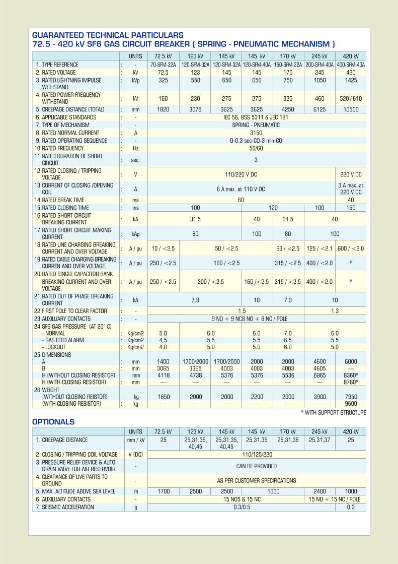
GUARANTEED TECHNICAL PARTICULARS72.5 - 420 kV SF6 GAS CIRCUIT BREAKER ( SPRING - PNEUMATIC MECHANISM )
UNITS 72.5 kV 123 kV 145 kV 145 kV 170 kV 245 kV 420 kV1. TYPE REFERENCE : - 70-SFM-32A 120-SFM-32A 120-SFM-32A 120-SFM-40A 150-SFM-32A 200-SFM-40A 400-SFM-40A2. RATED VOLTAGE : kV 72.5 123 145 145 170 245 4203. RATED LIGHTNING IMPULSE : kVp 325 550 650 650 750 1050 1425
WITHSTAND4. RATED POWER FREQUENCY
: kV 160 230 275 275 325 460 520 / 610WITHSTAND5. CREEPAGE DISTANCE (TOTAL) : mm 1820 3075 3625 3625 4250 6125 105006. APPLICABLE STANDARDS : - IEC 56, BSS 5311 & JEC 1817. TYPE OF MECHANISM : - SPRING - PNEUMATIC8. RATED NORMAL CURRENT : A 31509. RATED OPERATING SEQUENCE : - O-0.3 sec-CO-3 min-CO
10.RATED FREQUENCY : Hz 50/6011.RATED DURATION OF SHORT
: sec. 3CIRCUIT12.RATED CLOSING / TRIPPING
: V 110/220 V DC 220 V DCVOLTAGE13.CURRENT OF CLOSING /OPENING
: A 6 A max. at 110 V DC3 A max. at
COIL 220 V DC14.RATED BREAK TIME : ms 60 4015.RATED CLOSING TIME : ms 100 120 100 15016.RATED SHORT CIRCUIT
: kA 31.5 40 31.5 40BREAKING CURRENT17.RATED SHORT CIRCUIT MAKING
: kAp 80 100 80 100CURRENT18.RATED LINE CHARGING BREAKING
: A / pu 10 / <2.5 50 / <2.5 63 / <2.5 125 / <2.1 600 / <2.0CURRENT AND OVER VOLTAGE19.RATED CABLE CHARGING BREAKING
: A / pu 250 / <2.5 160 / <2.5 315 / <2.5 400 / <2.0 *CURREN AND OVER VOLTAGE.20.RATED SINGLE CAPACITOR BANK
BREAKING CURRENT AND OVER : A / pu 250 / <2.5 300 / <2.5 160 /<2.5 315 / <2.5 400 / <2.0 *VOLTAGE.
21.RATED OUT OF PHASE BREAKING: kA 7.9 10 7.9 10CURRENT
22.FIRST POLE TO CLEAR FACTOR : - 1.5 1.323.AUXILLIARY CONTACTS : - 9 NO + 9 NC8 NO + 8 NC / POLE24.SF6 GAS PRESSURE (AT 20° C)
- NORMAL : Kg/cm2 5.0 6.0 6.0 7.0 6.0- GAS FEED ALARM : Kg/cm2 4.5 5.5 5.5 6.5 5.5- LOCKOUT : Kg/cm2 4.0 5.0 5.0 6.0 5.0
25.DIMENSIONSA : mm 1400 1700/2000 1700/2000 2000 2000 4600 6000B : mm 3065 3365 4003 4003 4003 4605 —H (WITHOUT CLOSING RESISTOR) : mm 4118 4738 5376 5376 5536 6965 8360*H (WITH CLOSING RESISTOR) : mm — — — — — — 8760*
26.WEIGHT(WITHOUT CLOSING REISTOR) : kg 1650 2000 2000 2200 2000 3900 7950(WITH CLOSING RESISTOR) : kg — — — — — — 9600
* WITH SUPPORT STRUCTURE
OPTIONALSUNITS 72.5 kV 123 kV 145 kV 145 kV 170 kV 245 kV 420 kV
1. CREEPAGE DISTANCE mm / kV 25 25,31,35, 25,31,35, 25,31,35 25,31,38 25,31,37 2540,45 40,45
2. CLOSING / TRIPPING COIL VOLTAGE V (DC) 110/125/2203. PRESSURE RELIEF DEVICE & AUTO
- CAN BE PROVIDEDDRAIN VALVE FOR AIR RESERVOIR4. CLEARANCE OF LIVE PARTS TO
- AS PER CUSTOMER SPECIFICATIONSGROUND5. MAX. ALTITUDE ABOVE SEA LEVEL m 1700 2500 2500 1000 2400 10006. AUXILLIARY CONTACTS - 15 NO5 & 15 NC 15 NO + 15 NC / POLE7. SEISMIC ACCELERATION g 0.3/0.5 0.3
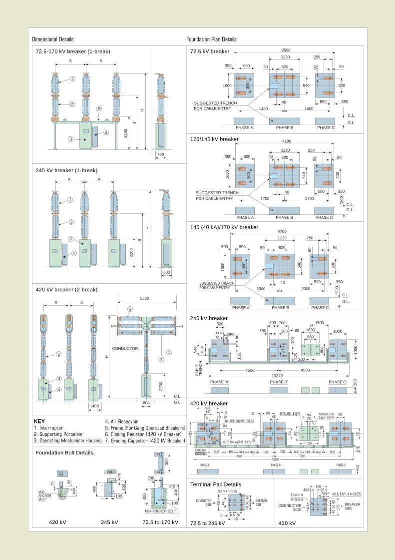
Dimensional Details
72.5-170 kV breaker (1-break)
245 kV breaker (1-break)
420 kV breaker (2-break)
Foundation Bolt Details
A A
2200
B
H
700
2
1
5
4
3
3
2
1
A A
2200
B
H
800
4
3
2
1400
4
800
2230
C.L.
G.L.
CONDUCTOR
H
7
1
6
5320A A
4. Air Reservoir5. Frame (For Gang Operated Breakers)6. Closing Resistor (420 kV Breaker)7. Grading Capacitor (420 kV Breaker)
KEY1. Interrupter2. Supporting Porcelain3. Operating Mechanism Housing
420 kV 245 kV 72.5 to 170 kV
400 40
0
100
M24-ANCHOR BOLT
200
300
55
72.5 kV breaker
Foundation Plan Details
123/145 kV breaker
145 (40 kA)/170 kV breaker
72.5 to 245 kV
245 kV breaker
420 kV breaker
Terminal Pad Details
4100
1220
52050 5080
300
540
500
1700
350
*300
C.L.G.L.
40
1700
500
1000
SUGGESTED TRENCHFOR CABLE ENTRY
300
350
250
PHASE A PHASE B PHASE C
C.L.
G.L.
*300
350500
20002000
40SUGGESTED TRENCHFOR CABLE ENTRY
300
540
300
1000
50
80
250
4700
1220
52050500500
PHASE A PHASE B PHASE C
1000
500350
SUGGESTED TRENCHFOR CABLE ENTRY 1400
50 520 80 50
2501220
3500
40
1400
500 350
300
C.L.
G.L.
300 540
PHASE A PHASE B PHASE C
300
==520
250
8016
5540
==
PHASE 'A' PHASE'B'
100
180
700490
80150
1500
1000
1000
PHASE'C'
50
4500 4500
525
250
800
1000
580
200
10270CA
BLE
TR
EN
CH
400
70
100
400
300
AIRPIPE
430
250
TRENCH FORCABLE ENTRY
4NOS.,M24 BOLTS
==
PHASE-C
160080
50100
250
200
1325CONDUITENTRANCE 1450 1450 1450 1325 1325 1450 1450 1450 1325
7000 700015870
PHASE-A PHASE-B
1600 730
HOLES FOR ANCHOR BOLTS 925
3x4 M30 ANCHOR BOLTS
150 820630= =
580200
= =
800
==
1000
730
630
==
730
300
63020
100
M30ANCHORBOLT
25 8063
0
420 kV
CONDUCTORSIDE 15
044.5
18ø × 4 HOLES
44.5 60140
4040
40
16
BREAKERSIDE
16044.5
2614ø × 4HOLES
44.5CONNECTOR
SIDE
M16 TAP, 4 HOLES
BREAKERSIDE
9036
4050
4017
0

Power SystemsA Business Unit of Crompton Greaves Ltd.SF6 Switchgear Divn.Switchgear ComplexA-3, MIDC, Ambad, Nashik - 422 010 IndiaTel: (+91) 253 382271 Ext 107/108/110Fax: (+91) 253 382219/381247E-mail: [email protected] (Exports)
[email protected] (General)URL: www.cgswgear.com
Regd. Office : 6th Floor, CG House, Dr. Annie Besant Road, Prabhadevi, Mumbai - 400 025, India.Data subject to change
The Thapar Group
CG-S&C/EXP/Cat.No.SF6-105/3/01/2000
Quality through care. Care through quality.