Embed Size (px)
Citation preview

PUBLISHED SFF-8682 Rev 1.1
QSFP+ 4X Connector Page 1
Copyright © 2018 SNIA. All rights reserved.
SFF specifications are available at http://www.snia.org/sff/specifications
SFF-8682
Specification for
QSFP+ 4X Connector
Rev 1.1 June 8, 2018
Secretariat: SFF TA TWG
Abstract: This specification defines the physical interface and general
performance requirements of the QSFP+ 0.8mm Connector that is designed for use in
high speed serial interconnect applications. One such use is as the QSFP+ host
receptacle mated to QSFP+ modules or cables.
This specification provides a common reference for systems manufacturers, system
integrators, and suppliers.
This specification is made available for public review, and written comments are
solicited from readers. Comments received by the members will be considered for
inclusion in future revisions of this specification.
The description of a connector in this specification does not assure that the
specific component is actually available from connector suppliers. If such a
connector is supplied it must comply with this specification to achieve
interoperability between suppliers.
POINTS OF CONTACT:
Jay Neer
Molex, LLC.
2222 Wellington Ct.
Lisle, IL 60532
Ph: 561-251-8016
Chairman SFF TA TWG
Email: [email protected]

PUBLISHED SFF-8682 Rev 1.1
QSFP+ 4X Connector Page 2
Copyright © 2018 SNIA. All rights reserved.
Intellectual Property
The user's attention is called to the possibility that implementation of this
Specification may require the use of an invention covered by patent rights. By
distribution of this specification, no position is taken with respect to the
validity of a claim or claims or of any patent rights in connection therewith.
This specification is considered SNIA Architecture and is covered by the SNIA IP
Policy and as a result goes through a request for disclosure when it is published.
Additional information can be found at the following locations:
• Results of IP Disclosures: http://www.snia.org/sffdisclosures
• SNIA IP Policy: http://www.snia.org/ippolicy
Change History
May 30, 2012 (First draft):
- Produced from the SFF-8662 rev 2.2 with appropriate data rate changes to the
text
Rev 0.4:
- Corrected speed ratings of this specification and referenced specifications.
Rev 0.5:
- Harmonized values of B20/B21 and C02/C03 with SFF-8662
Rev 0.6:
- Replaced Figure 4-1
- Added Datum H to Figure 6-1
Rev 0.7:
- Speed removed from title and text as it is referenced by multiple variants
- Corrected introduced error in Tolerance of A01*2
Rev 0.8:
- Expanded the list of references in Section 1.1 and Section 1.2
- Removed Style B from title
Rev 1.0 (March 2, 2018):
- Updated to SNIA format
- Revised abstract
- Reformatted Change History
- Fixed broken links in Foreword
- Updated Applications (Section 1.1)
- Added EIA document references
- Clarified “fixed” and “free” definitions
- All references to “pluggable modules,” “plugs,” or “modules” changed to
“module”; added definition for module
- Minor editorial issues resolved
- The tolerance for lead-in chamfer (dimension A16) was changed from 0.05mm to
0.10mm. The 0.05mm tolerance was found to be too tight to be easily
manufactured in large volumes. This change was made based on the results of
the straw poll that closed January 12, 2018.
- Updated Section 7 (Connector Performance Requirements) to agree with other
SFF documents for QSFP
- NOTE: During the review period for this revision, a comment to make the
connector footprint informative was submitted. Resolution of this comment has
been deferred until a future revision of this specification.
Rev 1.1 (June 8, 2018):
- Updated tolerance of dimension A14 in Table 6-1.

PUBLISHED SFF-8682 Rev 1.1
QSFP+ 4X Connector Page 3
Copyright © 2018 SNIA. All rights reserved.
Foreword
The development work on this specification was done by the SNIA SFF TWG, an
industry group. Since its formation as the SFF Committee in August 1990, the
membership has included a mix of companies which are leaders across the industry.
When 2 1/2" diameter disk drives were introduced, there was no commonality on
external dimensions e.g. physical size, mounting locations, connector type,
connector location, between vendors. The SFF Committee provided a forum for system
integrators and vendors to define the form factor of disk drives.
During their definition, other activities were suggested because participants in
SFF faced more challenges than the form factors. In November 1992, the charter was
expanded to address any issues of general interest and concern to the storage
industry. The SFF Committee became a forum for resolving industry issues that are
either not addressed by the standards process or need an immediate solution.
In July 2016, the SFF Committee transitioned to SNIA (Storage Networking Industry
Association), as a TA (Technology Affiliate) TWG (Technical Work Group).
Industry consensus is not a requirement to publish a specification because it is
recognized that in an emerging product area, there is room for more than one
approach. By making the documentation on competing proposals available, an
integrator can examine the alternatives available and select the product that is
felt to be most suitable.
SFF meets during the T10 (see www.t10.org) and T11 (see www.t11.org) weeks, and
SSWGs (Specific Subject Working Groups) are held at the convenience of the
participants.
Many of the specifications developed by SFF have either been incorporated into
standards or adopted as standards by ANSI, EIA, JEDEC and SAE.
For those who wish to participate in the activities of the SFF TWG, the signup for
membership can be found at:
http://www.snia.org/sff/join
The complete list of SFF Specifications which have been completed or are currently
being worked on by the SFF Committee is contained in the document SFF-8000 which
can be found at:
http://www.snia.org/sff/specifications
Suggestions for improvement of this specification will be welcome, they should be
submitted to:
http://www.snia.org/feedback

PUBLISHED SFF-8682 Rev 1.1
QSFP+ 4X Connector Page 4
Copyright © 2018 SNIA. All rights reserved.
CONTENTS
1. Scope 5 1.1 Application Specific Criteria 5 1.2 Copyright 5 1.3 Disclaimer 5
2. References 6 2.1 Industry Documents 6 2.2 Sources 6 2.3 Conventions 6 2.4 Definitions 7
3. General Description 10
4. Datums 11
5. Connector Description 12
6. Connector Dimensions 13 6.1 Free (Module) Paddle Card 13 6.2 Fixed (Receptacle) Right Angle Connector 15 6.3 Fixed (Receptacle) Right Angle Connector Footprint 17
7. Connector Performance Requirements 18
FIGURES
Figure 2-1 Fixed and Free Definition 8 Figure 4-1 Datum Definitions 11 Figure 5-1 General View of Fixed (Receptacle) 12 Figure 6-1 Free (Module) Paddle Card 13 Figure 6-2 Fixed (Receptacle) Right Angle Connector 15 Figure 6-3 Fixed (Receptacle) Right Angle Conenctor Footprint 17
TABLES
Table 4-1 Datum Descriptions 11 Table 6-1 Free (Module) Paddle Card Dimensions 14 Table 6-2 Fixed (Receptacle) Right Angle Connector Dimensions 16 Table 6-3 Fixed (Receptacle) Right Angle Connector Footprint Dimensions 17 Table 7-1 TS-1000 Test Parameters 18 Table 7-2 Electrical Test Parameters 18 Table 7-3 Mechanical Performance Requirements 19 Table 7-4 Environmental Performance Requirements 19

PUBLISHED SFF-8682 Rev 1.1
QSFP+ 4X Connector Page 5
Copyright © 2018 SNIA. All rights reserved.
1. Scope
This specification was developed in conjunction with the InfiniBand Trade
Association. It defines the terminology and physical requirements for the mating
interface and physical embodiment of the 0.8mm Connector. See SFF-8683 for the
mechanical design of the Cage/Shield which enables a shielded interface and SFF-
8661 for the physical embodiment of the mating module.
InfiniBand, Ethernet, SAS, and other standards define requirements on the
characteristic impedance and ability to transmit multi-gigabit signals for cable
assemblies and backplanes. When this connector is used in such an application, it
is subject to the requirements of the appropriate standard.
1.1 Application Specific Criteria
SAS, InfiniBand, IEEE, and Fibre Channel define respective electrical performance
requirements for the transmission of multi-gigabit signals through this interface.
When this connector is used for any of these applications, its performance shall
meet the requirements of the appropriate standard. This connector shall intermate
with previous generations of lower speed QSFP connectors.
1.2 Copyright
The SNIA hereby grants permission for individuals to use this document for personal
use only, and for corporations and other business entities to use this document for
internal use only (including internal copying, distribution, and display) provided
that:
1. Any text, diagram, chart, table or definition reproduced shall be
reproduced in its entirety with no alteration, and,
2. Any document, printed or electronic, in which material from this document
(or any portion hereof) is reproduced shall acknowledge the SNIA copyright
on that material, and shall credit the SNIA for granting permission for its
reuse.
Other than as explicitly provided above, there may be no commercial use of this
document, or sale of any part, or this entire document, or distribution of this
document to third parties. All rights not explicitly granted are expressly reserved
to SNIA.
Permission to use this document for purposes other than those enumerated
(Exception) above may be requested by e-mailing [email protected]. Please
include the identity of the requesting individual and/or company and a brief
description of the purpose, nature, and scope of the requested use. Permission for
the Exception shall not be unreasonably withheld. It can be assumed permission is
granted if the Exception request is not acknowledged within ten (10) business days
of SNIA's receipt. Any denial of permission for the Exception shall include an
explanation of such refusal.
1.3 Disclaimer
The information contained in this publication is subject to change without notice.
The SNIA makes no warranty of any kind with regard to this specification,
including, but not limited to, the implied warranties of merchantability and
fitness for a particular purpose. The SNIA shall not be liable for errors contained
herein or for incidental or consequential damages in connection with the
furnishing, performance, or use of this specification.
Suggestions for revisions should be directed to http://www.snia.org/feedback/
PUBLISHED SFF-8682 Rev 1.1
QSFP+ 4X Connector Page 6
Copyright © 2018 SNIA. All rights reserved.
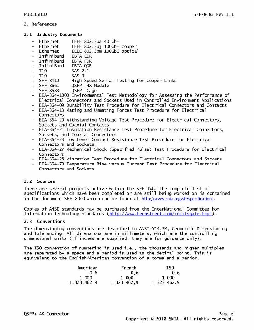
2. References
2.1 Industry Documents
- Ethernet IEEE 802.3ba 40 GbE
- Ethernet IEEE 802.3bj 100GbE copper
- Ethernet IEEE 802.3bm 100GbE optical
- Infiniband IBTA EDR
- Infiniband IBTA FDR
- InfiniBand IBTA QDR
- T10 SAS 2.1
- T10 SAS 3
- SFF-8410 High Speed Serial Testing for Copper Links
- SFF-8661 QSFP+ 4X Module
- SFF-8683 QSFP+ Cage
- EIA-364-1000 Environmental Test Methodology for Assessing the Performance of
Electrical Connectors and Sockets Used in Controlled Environment Applications
- EIA-364-09 Durability Test Procedure for Electrical Connectors and Contacts
- EIA-364-13 Mating and Unmating Forces Test Procedure for Electrical
Connectors
- EIA-364-20 Withstanding Voltage Test Procedure for Electrical Connectors,
Sockets and Coaxial Contacts
- EIA-364-21 Insulation Resistance Test Procedure for Electrical Connectors,
Sockets, and Coaxial Connectors
- EIA-364-23 Low Level Contact Resistance Test Procedure for Electrical
Connectors and Sockets
- EIA-364-27 Mechanical Shock (Specified Pulse) Test Procedure for Electrical
Connectors
- EIA-364-28 Vibration Test Procedure for Electrical Connectors and Sockets
- EIA-364-70 Temperature Rise versus Current Test Procedure for Electrical
Connectors and Sockets
2.2 Sources
There are several projects active within the SFF TWG. The complete list of
specifications which have been completed or are still being worked on is contained
in the document SFF-8000 which can be found at http://www.snia.org/sff/specifications.
Copies of ANSI standards may be purchased from the InterNational Committee for
Information Technology Standards (http://www.techstreet.com/incitsgate.tmpl).
2.3 Conventions
The dimensioning conventions are described in ANSI-Y14.5M, Geometric Dimensioning
and Tolerancing. All dimensions are in millimeters, which are the controlling
dimensional units (if inches are supplied, they are for guidance only).
The ISO convention of numbering is used i.e., the thousands and higher multiples
are separated by a space and a period is used as the decimal point. This is
equivalent to the English/American convention of a comma and a period.
American French ISO
0.6 0,6 0.6
1,000 1 000 1 000
1,323,462.9 1 323 462,9 1 323 462.9

PUBLISHED SFF-8682 Rev 1.1
QSFP+ 4X Connector Page 7
Copyright © 2018 SNIA. All rights reserved.
2.4 Definitions
For the purpose of SFF Specifications, the following definitions apply:
Advanced grounding contacts: Connector contacts that make first and break last and
are capable of carrying power ground return currents and performing electrostatic
discharge. Other terms sometimes used to describe these features are: grounding
pins, ESD contacts, grounding contacts, static drain, and pre-grounding contacts.
Alignment guides: Connector features that preposition insulators prior to
electrical contact. Other terms sometimes used to describe these features are:
guide pins, guide posts, blind mating features, mating features, alignment
features, and mating guides
Board Termination Technologies: Surface mount single row, surface mount dual row,
through hole, hybrid, straddle mount, pressfit.
Cable Termination: The attachment of wires to the termination side of a connector.
Schemes commonly used in the industry are IDC (Insulation Displacement Contact),
IDT (Insulation Displacement Termination), wire slots, solder, weld, crimp, braise,
etc.
Contact mating sequence: Order of electrical contact during mating/unmating
process. Other terms sometimes used to describe this feature are: contact
sequencing, contact positioning, make first/break last, EMLB (early make late
break) staggered contacts, and long pin / short pin.
Fixed: Adopted from EIA standard terminology as the gender that most commonly
exists on the fixed end of a connection, for example, on the board or bulkhead
side. In this specification "fixed" is specifically used to describe the mating
side gender illustrated in Figure 2-1. It is typically used to describe the gender
of the mating side of the connector that accepts its mate upon mating. Other common
terms are “receptacle,” “female,” and “socket connector.”
Fixed Board: A connector that uses a fixed gender mating side and a termination
side suitable for any of the printed circuit board termination technologies.
Free: Adopted from EIA standard terminology as the gender that most commonly
exists on the free end of a connection, for example, on the cable side. In this
specification "free" is specifically used to describe the mating side gender
illustrated in Figure 2-1. It is typically used to describe the gender of the
mating side of the connector that penetrates its mate upon mating. Other common
terms are "plug” or “module," "male," and "pin connector.”.
Free Board: A connector that uses a free gender mating side and a termination side
suitable for any of the printed circuit board termination technologies
Frontshell: That metallic part of a connector body that directly contacts the
backshell or other shielding material that provides mechanical and shielding
continuity between the connector and the cable media. Other terms sometimes used to
describe this part of a cable assembly are: housing, nosepiece, cowling, and metal
shroud.
Height: Distance from board surface to farthest overall connector feature

PUBLISHED SFF-8682 Rev 1.1
QSFP+ 4X Connector Page 8
Copyright © 2018 SNIA. All rights reserved.
Mating side: The side of the connector that joins and separates from the mating
side of a connector of opposite gender. Other terms commonly used in the industry
are mating interface, separable interface and mating face.
FIGURE 2-1 FIXED AND FREE DEFINITION
Module: In this specification, refers to direct attach copper (DAC), direct attach
optics, and pluggable optics.
Offset: An alignment shift from the center line of the connector
Optional: This term describes features which are not required by the SFF
Specification. However, if any feature defined by the SFF Specification is
implemented, it shall be done in the same way as defined by the Specification.
Describing a feature as optional in the text is done to assist the reader. If there
is a conflict between text and tables on a feature described as optional, the table
shall be accepted as being correct.
QSFP: Quad Small Formfactor Pluggable
Reserved: Where this term is used for defining the signal on a connector contact
its actual function is set aside for future standardization. It is not available
for vendor specific use. Where this term is used for bits, bytes, fields and code
values; the bits, bytes, fields and code values are set aside for future
standardization. The default value shall be zero. The originator is required to
define a Reserved field or bit as zero, but the receiver should not check Reserved
fields or bits for zero.
Right Angle: A connector design for use with printed circuit board assembly
technology where the mating direction is parallel to the plane of the printed
circuit board
Single row: A connector design for use with surface mount printed circuit board
assembly technology where the termination side points are arranged in one line
Single sided termination: A cable termination assembly style and a connector
design style where only one side of the connector is accessible when attaching
wires. This style frequently has IDC termination points that point in the same
direction.
SMT: Surface Mount Technology
Straddle mount: A connector design style and a printed circuit board design style
that uses surface mount termination points on both sides of the board. The
connector is frequently centered between the top and bottom surfaces of the board.
Straight: A connector design for use with printed circuit board assembly
technology where the mating direction is perpendicular to the plane of the printed
circuit board

PUBLISHED SFF-8682 Rev 1.1
QSFP+ 4X Connector Page 9
Copyright © 2018 SNIA. All rights reserved.
Surface mount: A connector design and a printed circuit board design style where
the connector termination points do not penetrate the printed circuit board and are
subsequently soldered to the printed circuit board
Termination side: The side of the connector opposite the mating side that is used
for permanently attaching conductors to the connector. Due to contact numbering
differences between mating side genders the termination side shall always be
specified in conjunction with a mating side of a specific gender. Other terms
commonly used in the industry are: back end, non-mating side, footprint, pc board
side, and post side
Through hole: A connector design and a printed circuit board design style where
the connector termination points penetrates the printed circuit board and are
subsequently soldered to the printed circuit board.

PUBLISHED SFF-8682 Rev 1.1
QSFP+ 4X Connector Page 10
Copyright © 2018 SNIA. All rights reserved.
3. General Description
The 0.8 mm connection system is based on industry-proven card edge style contacts,
which mate with a single wipe, and are physically robust.
The mating interfaces of paddle card to receptacle body and receptacle body to
circuit board are enabled with SFF-8683 Cage.
The cage/shield is mounted separately to the host board so that the stress imposed
by insertion and removal of the module does not affect the signal/body solder
joints.
This connector system was designed to satisfy the needs for high speed serial data
transmission applications. Design goals were minimization of crosstalk and minimum
transmission line impedance discontinuity across the connector interface on both
rows of contacts.
The transmission line impedance of the connector itself (not including the
termination interface to the wire or board) matches the electrical bulk cable
within the tolerances allowed for the bulk cable. This connection scheme may be
used in multiple places within a cabling environment. Though it has been designed
for a 100 Ohm environment this connector will function acceptably at other
impedance levels (to be optimized on a case by case basis).
This specification includes the Minimum lengths, widths, and positional tolerances
of the contacts.
The connector is of a straightforward construction that does not rely on advanced
materials or processes while offering superior performance.

PUBLISHED SFF-8682 Rev 1.1
QSFP+ 4X Connector Page 11
Copyright © 2018 SNIA. All rights reserved.
4. Datums
FIGURE 4-1 DATUM DEFINITIONS
TABLE 4-1 DATUM DESCRIPTIONS
Datum Description
A Host Board Top Surface
C Distance between Connector Housing Pegs on host board
G Width of Module pc board
H Leading edge of signal contact pads on Module pc board
J Top surface of Module pc board
K Host board thru hole #1 to accept connector guide post
L Host board thru hole #2 to accept connector guide post
N Connector alignment pin
AA Connector slot width
BB Seating plane of cage on host board

PUBLISHED SFF-8682 Rev 1.1
QSFP+ 4X Connector Page 12
Copyright © 2018 SNIA. All rights reserved.
5. Connector Description
The 0.8mm connector relies on a receiving body and paddle card, which are the
primary elements to construct connectors.
The primary elements provide a flexible means to implement solutions for diverse
applications e.g., direct board-to-board implementations can incorporate the module
into the side of one board and mate directly to a receiving body on the other.
Figure 5-1 is an example, which illustrates a receiving body and how it becomes a
receptacle to receive the module.
FIGURE 5-1 GENERAL VIEW OF FIXED (RECEPTACLE)
The entire interface is defined and controlled by SFF-8661, SFF-8682, and SFF-8683.
SFF-8661 defines the free module that incorporates the paddle card and the shell,
which are used to form a complete assembly for use in shielded applications.
SFF-8683 defines the shell/cage which provides guidance and retention for the free
module, and absorbs the stress imposed by insertion and removal of the module. This
protects the signal quality of the solder joints to the body.

PUBLISHED SFF-8682 Rev 1.1
QSFP+ 4X Connector Page 13
Copyright © 2018 SNIA. All rights reserved.
6. Connector Dimensions
The dimensioning conventions are described in ANSI-Y14.5M, Dimensioning and
Tolerancing. All dimensions are in millimeters.
Dimension related requirements for the connector system addressed in this
specification are specified in the tables and figures in this clause.
6.1 Free (Module) Paddle Card
FIGURE 6-1 FREE (MODULE) PADDLE CARD

PUBLISHED SFF-8682 Rev 1.1
QSFP+ 4X Connector Page 14
Copyright © 2018 SNIA. All rights reserved.
TABLE 6-1 FREE (MODULE) PADDLE CARD DIMENSIONS
Designator Description Dimension Tolerance (±)
A01 (*1) Paddle Card Width (Pad Contact Width 0.54) 16.42 0.08
A01 (*2) Paddle Card Width (Pad Contact Width 0.60) 16.40 0.10
A02 Paddle Card Thickness (across pads) 1.00 0.10
A03 First to Last Pad Centers 14.40 Basic
A04 Card Center to Outer Pad Center 7.00 Basic
A05 Card Center to Outer Pad Center 7.40 Basic
A06 Pad Center to Center (Pitch) 0.80 Basic
A07 (*1) Pad Contact Width (Paddle Card Width 16.42) 0.54 0.04
A07 (*2) Pad Contact Width (Paddle Card Width 16.40) 0.60 0.03
A08 Pad Length - Third Mate 1.60 Min.
A09 Third Mate to Card Edge (see note re Datum H) 1.45 0.10
A10 Third Mate to First Mate 0.90 0.05
A11 Third Mate to Second Mate 0.40 0.05
A12 Pad to Pre-Pad 0.10 0.05
A13 Component Keep Out Area 5.40 Min.
A14 Lead-in Chamfer x 45 degrees 0.50 0.10
A15 Third Mate Pad to Datum H 0.00 0.03
A16 Lead-in Chamfer x 45 degrees 0.30 0.10
A17 Lead-in Flat 0.40 Ref
Mating sequence: First Mate - Ground Contacts
Second Mate - Power Contacts
Third Mate - Signal Contacts
(*) Dimensions of the Pad Contact Width and the Paddle Card Width are such that the
centerline of the terminal does not go off the edge of the Pad.
An implementer may use either 16.42/0.54 or 16.40/0.60 for the A01/A07 dimensions.
PUBLISHED SFF-8682 Rev 1.1
QSFP+ 4X Connector Page 15
Copyright © 2018 SNIA. All rights reserved.
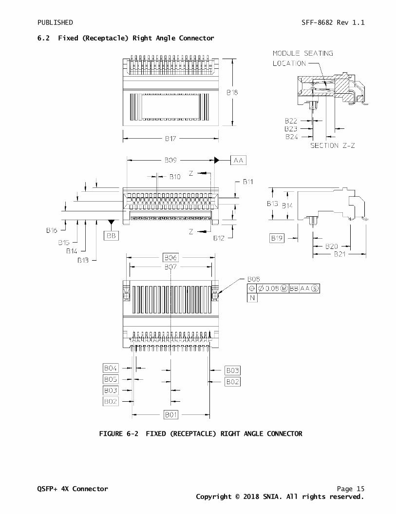
6.2 Fixed (Receptacle) Right Angle Connector
FIGURE 6-2 FIXED (RECEPTACLE) RIGHT ANGLE CONNECTOR

PUBLISHED SFF-8682 Rev 1.1
QSFP+ 4X Connector Page 16
Copyright © 2018 SNIA. All rights reserved.
TABLE 6-2 FIXED (RECEPTACLE) RIGHT ANGLE CONNECTOR DIMENSIONS
Designator Description Dimension Tolerance (±)
B01 First to Last Contact 14.80 Basic
B02 Centerline to First Contact 7.00 Basic
B03 Centerline to Last Contact 7.40 Basic
B04 Contact Pitch (within Row) 0.80 Basic
B05 Contact Pitch (Row to Row) 0.40 Basic
B06 Peg to Peg 16.8 Basic
B07 Leg to Leg 15.53 0.13
B08 Peg Diameter 1.40 0.05
B09 Card Slot Width 16.60 0.10
B10 (*) Contact Zone (0.18 wide terminal) 0.30 Max
Contact Zone (0.20 wide terminal) 0.32 Max
Contact Zone (0.22 wide terminal) 0.34 Max
Contact Zone (0.25 wide terminal) 0.37 Max
B11 Card Slot Height 1.14 Min
B12 Peg Length 0.95 0.13
B13 Overall Height 6.23 Max
B14 Mating Zone Height 5.35 0.13
B15 PCB to Card Slot Centerline 3.50 0.10
B16 Height Under Receptacle 1.65 0.08
B17 Receptacle Width 18.20 0.10
B18 Receptacle Length 12.82 Max
B19 Front Face to Peg 2.90 Basic
B20 Peg to Row A 5.18 0.10
B21 Peg to Row B 7.69 0.10
B22 Peg to Contact Centerline 0.00 0.10
B23 Card Slot Depth 3.25 Min
B24 Paddle Card Seating Location 2.50 Ref
(*) Note: Contact Zone is defined as a zone with its centerline located
at the theoretical contact centerline and the contact must always be
completely located within it

PUBLISHED SFF-8682 Rev 1.1
QSFP+ 4X Connector Page 17
Copyright © 2018 SNIA. All rights reserved.
6.3 Fixed (Receptacle) Right Angle Connector Footprint
FIGURE 6-3 FIXED (RECEPTACLE) RIGHT ANGLE CONENCTOR FOOTPRINT
TABLE 6-3 FIXED (RECEPTACLE) RIGHT ANGLE CONNECTOR FOOTPRINT DIMENSIONS
Designator Description Dimension Tolerance (±)
C01 Locating Hole to Hole 16.80 Basic
C02 Locating Hole to Row A 5.18 Basic
C03 Row A to Row B 2.51 Basic
C04 Card Center to Outer Pad Center 7.00 Basic
C05 Card Center to Outer Pad Center 7.40 Basic
C06 Card Center to Inner Pad Center 0.20 Basic
C07 Pad Pitch 0.80 Basic
C08 Pad Width 0.35 0.03
C09 Pad Length 1.80 0.03
C10 Locating Hole Diameter 1.55 0.05
C11 Card Center to Pad Center 0.20 Basic

PUBLISHED SFF-8682 Rev 1.1
QSFP+ 4X Connector Page 18
Copyright © 2018 SNIA. All rights reserved.
7. Connector Performance Requirements
The connector conforms to the test sequence as defined in EIA-364 TS-1000. The
following tables define the performance criteria and test procedures for those test
sequences.
TABLE 7-1 TS-1000 TEST PARAMETERS
Test Parameter Criteria
Durability Pre-condition: 25 cycles
Group 7: 100 cycles
Field Life (3, 5, 7, or 10 years) 10 years
Field Temperature (57, 60, 65, 75, or 85C) 65 degrees C
Test Group 4 Option Manufacturer to specify
Plating Type Precious
Surface Treatment Manufacturer to specify
TABLE 7-2 ELECTRICAL TEST PARAMETERS
Parameter Test Condition Specification
Current EIA 364-70
30 degree C temperature rise
-Signal contacts:
0.5 A per contact MAX
-Designated power contact:
1.0 A per contact MAX
Low Level Contact
Resistance
EIA 364-23
20 mVdc, 100 mA
20 mOhms deviations from
initial (baseline) contact
resistance
Insulation
Resistance
EIA 364-21
100 VDC between adjacent
contacts
1000M ohms minimum
Dielectric
Withstanding
Voltage
EIA 364-20
300 VDC minimum for 1 minute
between adjacent contacts
-1 mA MAX leakage
-No breakdown
Vibration EIA 364-28 -No damage
-No discontinuity longer than
1 microsecond allowed
-20 mOhm MAX change from
initial (baseline) contact
resistance
Mechanical Shock EIA 364-27 -No damage
-20 mOhm MAX change from
initial (baseline) contact
resistance

PUBLISHED SFF-8682 Rev 1.1
QSFP+ 4X Connector Page 19
Copyright © 2018 SNIA. All rights reserved.
TABLE 7-3 MECHANICAL PERFORMANCE REQUIREMENTS
Parameter Procedure Requirement1
Mating Force EIA 364-13
Test with connector, cage & module
(latch disengaged, without heat sink)
60N MAX
Unmating Force EIA 364-13
Test with connector, cage & module
(latch disengaged, without heat sink)
30N MAX
Contact Normal Force Manufacturer specified test to evaluate
the normal force applied by a single
contact
0.5N MIN
Connector/ Cage
Durability
EIA 364-09
Test with connector, cage & module2
100 cycles MIN
Module Durability EIA 364-09
Test with connector, cage & module
50 cycles MIN
NOTES:
1. In addition to the requirements listed, all parts must be free of visible damage after testing.
2. Modules may be replaced every 50 cycles.
TABLE 7-4 ENVIRONMENTAL PERFORMANCE REQUIREMENTS
Parameter Specification
Storage Temperature -20°C to +85°C
Humidity 80%