Embed Size (px)
Citation preview

SG-BWS-T4 SERIES Safety Control Unit
INSTRUCTION MANUAL
ORIGINAL INSTRUCTIONS (ref. 2006/42/EC)
DATALOGIC AUTOMATION Via Lavino 265 - 40050 Monte S.Pietro - Bologna – Italy Tel: +39 051 6765611- Fax: +39 051 6759324 www.automation.datalogic.com e-mail:[email protected]
DATALOGIC AUTOMATION reserves the right to make changes or improvements to products at any time without prior notice.
Datalogic and the Datalogic logo are registered trademarks of Datalogic S.p.A. in many countries, including the U.S.A. and the E.U.
826004302 rev.B © Copyright Datalogic 2009-2010

DECLARATION OF CONFORMITY EC-056
Rev.: 1
Pag.: 1 di 1
Datalogic Automation S.r.l. Via Lavino 265 40050 Monte San Pietro Bologna - Italy www.automation.datalogic.com
declares that the
SG-BWS-T4 ; CONTROL UNIT - ELECTRO-SENSITIVE PROTECTIVE EQUIPMENT (TYPE 4 ESPE)
and all its models are in conformity with the requirements of the European Council Directives listed below:
2006 / 42 / EC Machinery Directive
2004 / 108 / EC EMC Directive 2006 / 95 / EC Low Voltage Directive
____________________________________________
This Declaration is based upon compliance of the products to the following standards: EN 61496-1: 2004 SAFETY OF MACHINERY - ELECTRO-SENSITIVE PROTECTIVE EQUIPMENT.
PART 1: GENERAL REQUIREMENTS AN TESTS IEC 61496-2: 2006 SAFETY OF MACHINERY - ELECTRO-SENSITIVE PROTECTIVE EQUIPMENT. PART
2: PARTICULAR REQUIREMENTS FOR EQUIPMENT USING ACTIVE OPTO-ELECTRONIC PROTECTIVE DEVICES (AOPDS)
IEC 61508-1/3/4: 1998 IEC 61508-2:2000
FUNCTIONAL SAFETY OF ELECTRICAL/ELECTRONIC/PROGRAMMABLE ELECTRONIC
SAFETY-RELATED SYSTEMS.
EN ISO 13849-1: 2008 SAFETY OF MACHINERY -- SAFETY-RELATED PARTS OF CONTROL SYSTEMS -- PART 1: GENERAL PRINCIPLES FOR DESIGN
EN 50178:1997 ELECTRONIC EQUIPMENT FOR USE IN POWER INSTALLATIONS
EN 61000-6-2: 2005 ELECTROMAGNETIC COMPATIBILITY (EMC) PART 6-2: GENERIC STANDARDS - IMMUNITY FOR INDUSTRIAL ENVIRONMENTS
EN 55022 (CLASS A ITE): 2006 LIMITS AND METHODS OF MEASUREMENTS OF RADIO DISTURBANCE OF
INFORMATION TECHNOLOGY EQUIPMENT
Conformity has been certified by the following Notified/Competent Body (identification n° 0123): TÜV S ÜD Rail GmbH, Ridlerstrasse, 65 – D80339 München Datalogic Automation have a quality system certified by the CSQ, Nr. 9115.IES2, as per ISO 9001 and have therefore observed the regulations foreseen during development and production
Monte San Pietro, April 23th 2010
Paolo Morselli Quality Manager
UNI EN ISO 14001
BWS-T4 Series Instruction Manual
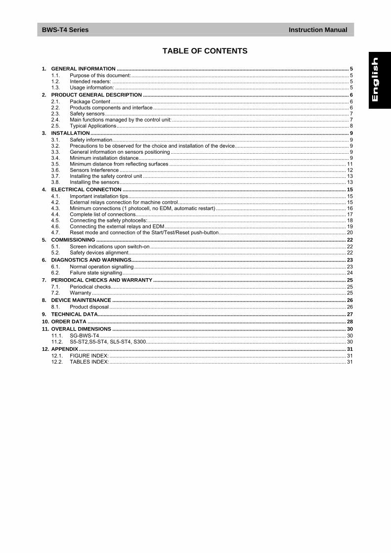
TABLE OF CONTENTS
1. GENERAL INFORMATION ............................................................................................................................................................... 5 1.1. Purpose of this document:..................................................................................................................................................... 5 1.2. Intended readers: .................................................................................................................................................................. 5 1.3. Usage information: ................................................................................................................................................................ 5
2. PRODUCT GENERAL DESCRIPTION ............................................................................................................................................. 6 2.1. Package Content ................................................................................................................................................................... 6 2.2. Products components and interface ...................................................................................................................................... 6 2.3. Safety sensors....................................................................................................................................................................... 7 2.4. Main functions managed by the control unit: ......................................................................................................................... 7 2.5. Typical Applications............................................................................................................................................................... 8
3. INSTALLATION................................................................................................................................................................................. 9 3.1. Safety information.................................................................................................................................................................. 9 3.2. Precautions to be observed for the choice and installation of the device.............................................................................. 9 3.3. General information on sensors positioning .......................................................................................................................... 9 3.4. Minimum installation distance................................................................................................................................................ 9 3.5. Minimum distance from reflecting surfaces ......................................................................................................................... 11 3.6. Sensors Interference ........................................................................................................................................................... 12 3.7. Installing the safety control unit ........................................................................................................................................... 13 3.8. Installing the sensors........................................................................................................................................................... 13
4. ELECTRICAL CONNECTION ......................................................................................................................................................... 15 4.1. Important installation tips..................................................................................................................................................... 15 4.2. External relays connection for machine control................................................................................................................... 15 4.3. Minimum connections (1 photocell, no EDM, automatic restart) ......................................................................................... 16 4.4. Complete list of connections................................................................................................................................................ 17 4.5. Connecting the safety photocells:........................................................................................................................................ 18 4.6. Connecting the external relays and EDM............................................................................................................................ 19 4.7. Reset mode and connection of the Start/Test/Reset push-button....................................................................................... 20
5. COMMISSIONING ........................................................................................................................................................................... 22 5.1. Screen indications upon switch-on ...................................................................................................................................... 22 5.2. Safety devices alignment..................................................................................................................................................... 22
6. DIAGNOSTICS AND WARNINGS................................................................................................................................................... 23 6.1. Normal operation signalling................................................................................................................................................. 23 6.2. Failure state signalling......................................................................................................................................................... 24
7. PERIODICAL CHECKS AND WARRANTY .................................................................................................................................... 25 7.1. Periodical checks................................................................................................................................................................. 25 7.2. Warranty .............................................................................................................................................................................. 25
8. DEVICE MAINTENANCE ................................................................................................................................................................ 26 8.1. Product disposal .................................................................................................................................................................. 26
9. TECHNICAL DATA.......................................................................................................................................................................... 27 10. ORDER DATA ................................................................................................................................................................................. 28 11. OVERALL DIMENSIONS ................................................................................................................................................................ 30
11.1. SG-BWS-T4......................................................................................................................................................................... 30 11.2. S5-ST2,S5-ST4, SL5-ST4, S300......................................................................................................................................... 30
12. APPENDIX ....................................................................................................................................................................................... 31 12.1. FIGURE INDEX: .................................................................................................................................................................. 31 12.2. TABLES INDEX:.................................................................................................................................................................. 31
Instruction Manual BWS-T4 Series
5
1. GENERAL INFORMATION Read this section carefully before implementing the instructions given in this manual and starting up the SG-BWS-T4 safety system.
1.1. Purpose of this document:
These instructions for use are addressed to the manufacturer technicians or staff operating the machine and give all necessary instructions for correct and safe assembly, setup, electric connection and commissioning of the SG-BWS-T4 safety system. Scope of this document excludes information about use of the machine the safety system is installed to.
1.2. Intended readers:
The instructions for use given herein are addressed to designers, manufacturers and persons in charge of the safety of systems to be equipped with the SG-BWS-T4. They are also addressed to the staff in charge of installing the SG-BWS-T4 to a machine, commissioning it or servicing it.
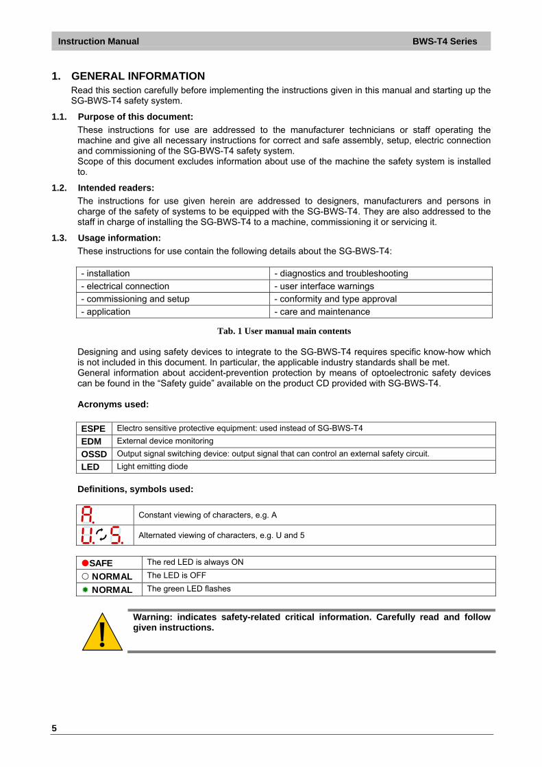
1.3. Usage information:
These instructions for use contain the following details about the SG-BWS-T4: - installation - diagnostics and troubleshooting
- electrical connection - user interface warnings
- commissioning and setup - conformity and type approval
- application - care and maintenance
Tab. 1 User manual main contents Designing and using safety devices to integrate to the SG-BWS-T4 requires specific know-how which is not included in this document. In particular, the applicable industry standards shall be met. General information about accident-prevention protection by means of optoelectronic safety devices can be found in the “Safety guide” available on the product CD provided with SG-BWS-T4. Acronyms used:
ESPE Electro sensitive protective equipment: used instead of SG-BWS-T4
EDM External device monitoring
OSSD Output signal switching device: output signal that can control an external safety circuit.
LED Light emitting diode
Definitions, symbols used:
Constant viewing of characters, e.g. A
Alternated viewing of characters, e.g. U and 5
SAFE The red LED is always ON
NORMAL The LED is OFF
NORMAL The green LED flashes
Warning: indicates safety-related critical information. Carefully read and follow given instructions.
BWS-T4 Series Instruction Manual
6
2. PRODUCT GENERAL DESCRIPTION
2.1. Package Content
Safety Control Unit SG-BWS-T4 Quick operations guide Cd-Rom with this user manual and other contents Six-monthly checklist for periodic check and maintenance
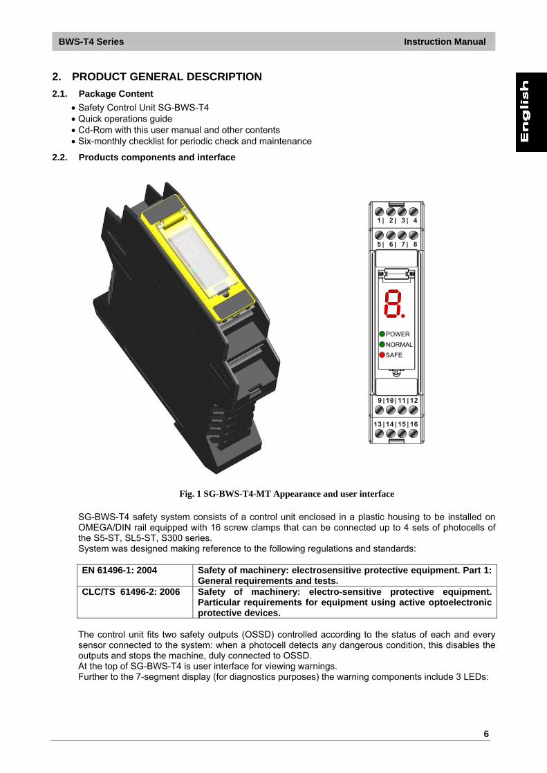
2.2. Products components and interface
Power
Safe
Break
5| 6| 7| 8
1| 2| 3| 4
9|10|11|12
13|14|15|16
POWER
NORMAL
SAFE
POWER
NORMAL
SAFE
Fig. 1 SG-BWS-T4-MT Appearance and user interface
SG-BWS-T4 safety system consists of a control unit enclosed in a plastic housing to be installed on OMEGA/DIN rail equipped with 16 screw clamps that can be connected up to 4 sets of photocells of the S5-ST, SL5-ST, S300 series. System was designed making reference to the following regulations and standards: EN 61496-1: 2004 Safety of machinery: electrosensitive protective equipment. Part 1:
General requirements and tests. CLC/TS 61496-2: 2006 Safety of machinery: electro-sensitive protective equipment.
Particular requirements for equipment using active optoelectronic protective devices.
The control unit fits two safety outputs (OSSD) controlled according to the status of each and every sensor connected to the system: when a photocell detects any dangerous condition, this disables the outputs and stops the machine, duly connected to OSSD. At the top of SG-BWS-T4 is user interface for viewing warnings. Further to the 7-segment display (for diagnostics purposes) the warning components include 3 LEDs:
Instruction Manual BWS-T4 Series
7
LED Indication POWER Device is powered correctly
NORMAL Safety outputs closed
SAFE Safety outputs open
Tab. 2 Signalling LEDs
2.3. Safety sensors
4 types of photocells can be connected to the safety control unit:
S5-5-X-X-SG-ST2: Type 2 safety photocell emitting infrared beams.
S5-5-X-X-SG-ST4: Type 4 safety photocell emitting infrared beams.
SL5-5-X-X-SG-ST4: Type 4 safety photocell emitting long-distance red laser beam.
S300-5-X-X-ST4: Type 4 safety photocell for long-distance applications.
See section 10 “Order data” for further details about available photocell models.
Using the above photocells independently from SG-BWS-T4 does not meet EN 61496-1 and CLC/TS 61496-2 requirements and is thus not allowed.
Connection of Type 2 photocells results in the whole system category downgrade to Type 2.
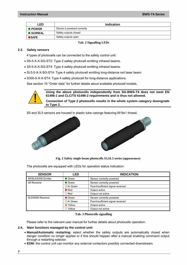
S5 and SL5 sensors are housed in plastic tube casings featuring M18x1 thread.
Fig. 2 Safety single beam photocells S5,SL5 series (appearance)
The photocells are equipped with LEDs for operation status indication:
SENSOR LED INDICATION S5/SL5/S300 Emitter Green Sensor correctly powered
Green Sensor correctly powered
/ Green Poor/insufficient signal received
Red Output active
S5 Receiver
Red Output not active
Green Sensor correctly powered
/ Green Poor/insufficient signal received
Yellow Output active
SL5/S300 Receiver
Yellow Output not active
Tab. 3 Photocells signalling
Please refer to the relevant user manual for further details about photocells operation.
2.4. Main functions managed by the control unit:
Manual/Automatic restarting: select whether the safety outputs are automatically closed when danger condition no longer applies or if this should happen after a manual enabling command output through a restarting selector.
EDM: the control unit can monitor any external contactors possibly connected downstream.

BWS-T4 Series Instruction Manual
8
2.5. Typical Applications
The SG-BWS-T4 system is typically used as a protection to the access to dangerous areas on machines or systems. The sensors are fixed and installed to the access area at the suitable safety distance from the nearest danger source and output a stop control to the machine or system, if the light beam is interrupted.
Hereafter are shown some application examples with SG-BWS-T4. Example 1: Automatic warehouses
The access of both moving bay sides has to be protected in order to prevent operators entering the dangerous area.
Fig. 3 Automatic warehouses protection with photocells
Solution: safety photocells are installed on both sides of the bay that are connected and driven by one SG-BWS-T4 control unit. Advantages: the use of tubular photocells enables installation even in reduced spaces in the warehouse structure. SG-BWS-T4 is ideal for all applications where protection has to be guaranteed without additional safety functions. Example 2: SMD machine protection
The access to a dangerous area must be enabled in order to carry-out maintenance procedures. The access must be allowed by stopping only the specific area by opening the doors and not the entire machine.
Fig. 4 Doors control by means of safety photocelss
Solution: SG-BWS-T4 is able to detect the door opening by using one or more photocells by intersecting the interrupted beams, guaranteeing the safety condition.
Advantages: all the safety interlocks can be replaced on each door thanks to the use of photocells and so reducing the plant cost as well as increasing flexibility.

Instruction Manual BWS-T4 Series
9
3. INSTALLATION
3.1. Safety information
For a correct and safe use of the SG-BWS-T4, the points considered in this section must be observed.
The stopping system of the machine must be electrically controlled. This control system must be able to stop the dangerous movement of the machine within the total machine stopping time T as per par. 3.4, and during all working cycle phases. The safety system should be installed and connected by a qualified technician in compliance with the instructions specified in this manual and industry rules. The photocells must be securely installed in a particular position so that access to the dangerous zone is not possible without the interruption of the beams (see 3.3 “General information on sensors positioning”). The personnel operating in the dangerous area must be well trained and must have adequate knowledge of all the operating procedures of the safety control unit. The START and TEST buttons must be located outside the protected area because the operator must check the protected area during all Test and Reset operations. Please carefully read the instructions for the correct functioning before powering the SG-BWS-T4.
3.2. Precautions to be observed for the choice and installation of the device
Make sure that the protection level assured by the device is compatible with the real danger level of the machine to be controlled, according to EN 954-1 and EN 13849-1.
The OSSD outputs of the ESPE must be used as machine stopping devices and not as command devices. The machine must have its own START command.
The dimension of the smallest object to be detected must be larger than the resolution level of the installed safety sensors.
The ESPE must be installed in a room complying with the technical characteristics indicated in section 9 “Technical data”.
Do not install the sensors close to strong and/or flashing light sources or close to similar devices. Strong electromagnetic disturbance might negatively affect device operation. Should this be the case
contact Datalogic Automation Technical Service. The operating distance of the safety sensors can be reduced in presence of smog, fog or airborne
dust. A sudden change in environment temperature, with very low minimum peaks, can generate a small
condensation layer on the sensors lenses and so jeopardise functioning.
3.3. General information on sensors positioning
Pay special care when positioning the safety photocells so to offer effective protection. The safety sensors should be installed in such a way that the dangerous area can only be entered after detecting the sensitive area. Photocells position is fixed by normative and must respect measures in Tab. 4.
Under standard operating conditions, machine starting must not be possible while operators are inside the dangerous area. If the operator is able to enter the dangerous area although ESPE positioning, an additional mechanical protection must be mounted to prevent the access.
3.4. Minimum installation distance
The safety device must be positioned at a specific safety distance. This distance must ensure that the dangerous area cannot be reached before the dangerous motion of the machine has been stopped by the ESPE. The safety distance depends on 4 factors, according to the EN-999 Standard:
Response time of the ESPE (the time between the effective sensors beam interruption and the opening of the SAFCN contacts).
BWS-T4 Series Instruction Manual
10
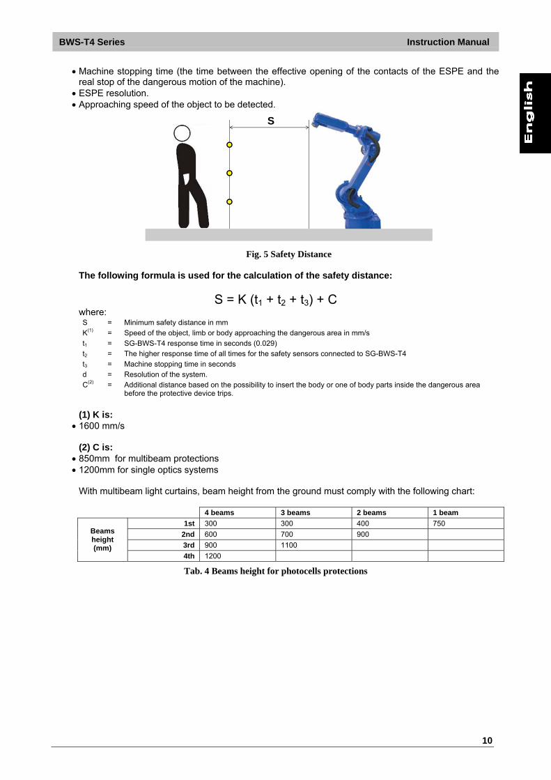
Machine stopping time (the time between the effective opening of the contacts of the ESPE and the real stop of the dangerous motion of the machine).
ESPE resolution. Approaching speed of the object to be detected.
S
Fig. 5 Safety Distance The following formula is used for the calculation of the safety distance:
S = K (t1 + t2 + t3) + C where: S = Minimum safety distance in mm
K(1) = Speed of the object, limb or body approaching the dangerous area in mm/s
t1 = SG-BWS-T4 response time in seconds (0.029)
t2 = The higher response time of all times for the safety sensors connected to SG-BWS-T4
t3 = Machine stopping time in seconds
d = Resolution of the system.
C(2) = Additional distance based on the possibility to insert the body or one of body parts inside the dangerous area before the protective device trips.
(1) K is:
1600 mm/s (2) C is:
850mm for multibeam protections 1200mm for single optics systems
With multibeam light curtains, beam height from the ground must comply with the following chart: 4 beams 3 beams 2 beams 1 beam
1st 300 300 400 750
2nd 600 700 900
3rd 900 1100
Beams height (mm)
4th 1200
Tab. 4 Beams height for photocells protections

Instruction Manual BWS-T4 Series
11
30
0m
m
60
0m
m
90
0m
m
12
00
mm
Fig. 6 Photocells installation heights for 4 beams protections
The reference standard is EN999 “Machine safety - the positioning of the protective device based on the approaching speed of the human body”. The following information is to be considered as indicative and concise. For correct safety distance please refer to complete standard EN-999.
Example: light curtain with 4 S5 photocells
S = K (t1 + t2 + t3) + C where: t1 = SG-BWS-T4 response time 29 ms
t2 = S5 response time 1.5 ms
t3 = machine total stopping time 290 ms
P = 850 mm for devices with resolution ≥ 40 mm. 850 mm
S = 1600 · 0.321 + 850 = 1364 mm 3.5. Minimum distance from reflecting surfaces
Reflecting surfaces placed near the light beams of the safety device (over, under or laterally) can cause passive reflections. These reflections can compromise the recognition of an object inside the controlled area. However, if the RX receiver detects a secondary beam (emitted again by the side-reflecting surface) the object might not be detected, even if the object interrupts the main beam.
Fig. 7 Distance from reflecting surfaces
BWS-T4 Series Instruction Manual
12
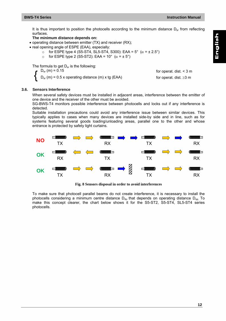
It is thus important to position the photocells according to the minimum distance Dsr from reflecting surfaces. The minimum distance depends on:
operating distance between emitter (TX) and receiver (RX); real opening angle of ESPE (EAA), especially:
o for ESPE type 4 (S5-ST4, SL5-ST4, S300): EAA = 5° ( = ± 2.5°) o for ESPE type 2 (S5-ST2): EAA = 10° ( = ± 5°)
The formula to get Dsr is the following:
Dsr (m) = 0.15 for operat. dist. < 3 m
{ Dsr (m) = 0.5 x operating distance (m) x tg (EAA) for operat. dist. 3 m
3.6. Sensors Interference
When several safety devices must be installed in adjacent areas, interference between the emitter of one device and the receiver of the other must be avoided. SG-BWS-T4 monitors possible interference between photocells and locks out if any interference is detected. Suitable installation precautions could avoid any interference issue between similar devices. This typically applies to cases when many devices are installed side-by side and in line, such as for systems featuring several goods loading/unloading areas, parallel one to the other and whose entrance is protected by safety light curtains.
NO TX RX TX RX
OK RX TX TX RX
OK TX RX TX RX
Fig. 8 Sensors disposal in order to avoid interferences
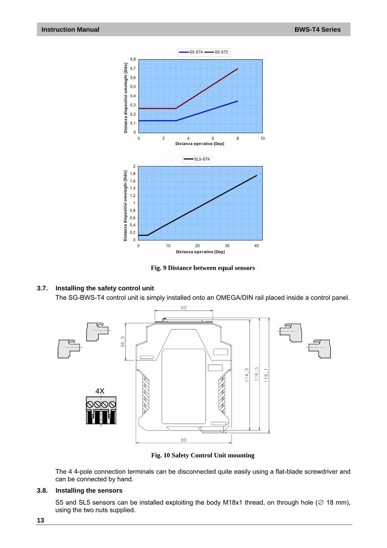
To make sure that photocell parallel beams do not create interference, it is necessary to install the photocells considering a minimum centre distance Ddo that depends on operating distance Dop. To make this concept clearer, the chart below shows it for the S5-ST2, S5-ST4, SL5-ST4 series photocells.
Instruction Manual BWS-T4 Series
13
0
0,1
0,2
0,3
0,4
0,5
0,6
0,7
0,8
0 2 4 6 8 10Distanza operativa (Dop)
Dis
tan
za d
isp
osi
tivi
om
olo
gh
i (D
do
)
S5-ST4 S5-ST2
0
0,2
0,4
0,6
0,8
1
1,2
1,4
1,6
1,8
2
0 10 20 30 40
Distanza operativa (Dop)
Dis
tan
za d
isp
osi
tivi
om
olo
gh
i (D
do
)
SL5-ST4
Fig. 9 Distance between equal sensors
3.7. Installing the safety control unit
The SG-BWS-T4 control unit is simply installed onto an OMEGA/DIN rail placed inside a control panel.
4X
Fig. 10 Safety Control Unit mounting
The 4 4-pole connection terminals can be disconnected quite easily using a flat-blade screwdriver and can be connected by hand.
3.8. Installing the sensors
S5 and SL5 sensors can be installed exploiting the body M18x1 thread, on through hole (∅ 18 mm), using the two nuts supplied.
BWS-T4 Series Instruction Manual
14
Various adjustable brackets are available to help sensor positioning (see 10.3 “Accessories”). Please refer to the photocell user manual for further details about installation.
Upon installation, make sure to correctly align the emitter and receiver. Emitter and receiver optics shall be on the same axis. Take any due precaution to reduce vibrations when application requirements are stricter than specifications indicated under section 9 “Technical data” During assembly, strictly comply with the instructions given under 3.4 “Minimum installation distance” and 3.5 “Minimum distance from reflecting surfaces”
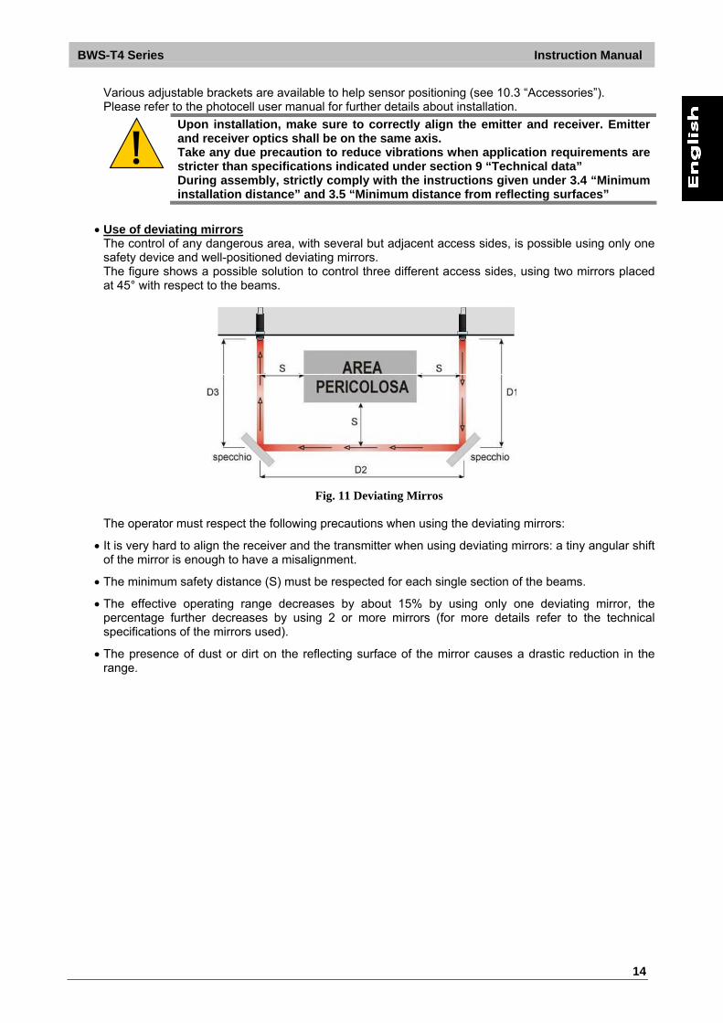
Use of deviating mirrors
The control of any dangerous area, with several but adjacent access sides, is possible using only one safety device and well-positioned deviating mirrors. The figure shows a possible solution to control three different access sides, using two mirrors placed at 45° with respect to the beams.
Fig. 11 Deviating Mirros
The operator must respect the following precautions when using the deviating mirrors:
It is very hard to align the receiver and the transmitter when using deviating mirrors: a tiny angular shift of the mirror is enough to have a misalignment.
The minimum safety distance (S) must be respected for each single section of the beams.
The effective operating range decreases by about 15% by using only one deviating mirror, the percentage further decreases by using 2 or more mirrors (for more details refer to the technical specifications of the mirrors used).
The presence of dust or dirt on the reflecting surface of the mirror causes a drastic reduction in the range.

Instruction Manual BWS-T4 Series
15
4. ELECTRICAL CONNECTION
4.1. Important installation tips
Do not place connection cables in contact with or near high-voltage cables and/or cable undergoing high current variations (e.g. motor power supplies, inverters, etc.); Do not connect in the same multi-pole cable the wires for control unit safety outputs or the OSSD wires of different light curtains. Do not connect in the same multi-pole cable both emitter and receiver of a set of photocells. All devices are protected internally against overvoltage and overcurrent: the use of other outer parts is not recommended.
4.2. External relays connection for machine control
For SG-BWS-T4 to work as a safety device an external MPCE (Machine Primary Control Equipment) must be connected that controls main machine power supply. Fig. 12 shows the connection to 2 external safety relays that can be monitored by SG-BWS-T4 by means of the EDM connection.
24VDC
K1K2
5| 6| 7| 8
1| 2| 3| 4
0VDC
NC NCEDM
Fig. 12 External Relay Connection
BWS-T4 Series Instruction Manual
16
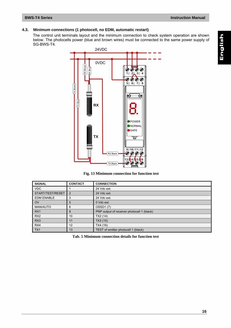
4.3. Minimum connections (1 photocell, no EDM, automatic restart)
The control unit terminals layout and the minimum connection to check system operation are shown below. The photocells power (blue and brown wires) must be connected to the same power supply of SG-BWS-T4.
Power
Safe
Break
5| 6| 7| 8
1| 2| 3| 4
24VDC
0VDC
TX
RX
RX Black
TX Black
9|10|11|12
13|14|15|16
POWER
NORMAL
SAFE
POWER
NORMAL
SAFE
RX
Blu
e
RX
Bro
wn
TX
Blu
e
TX
Bro
wn
Fig. 13 Minimum connection for function test
SIGNAL CONTACT CONNECTION
VDC 1 24 Vdc ext.
START/TEST/RESET 2 24 Vdc ext.
EDM ENABLE 3 24 Vdc ext.
OV 5 0 Vdc ext.
MAN/AUTO 6 OSSD1 (7)
RX1 9 PNP output of receiver photocell 1 (black)
RX2 10 TX2 (14)
RX3 11 TX3 (15)
RX4 12 TX4 (16)
TX1 13 TEST of emitter photocell 1 (black)
Tab. 5 Minimum connection details for function test
Instruction Manual BWS-T4 Series
17
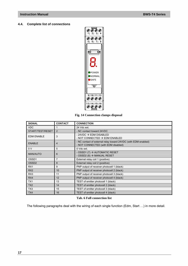
4.4. Complete list of connections
Power
Safe
Break
5| 6| 7| 8
1| 2| 3| 4
9|10|11|12
13|14|15|16
POWER
NORMAL
SAFE
POWER
NORMAL
SAFE
Fig. 14 Connection clamps disposal
SIGNAL CONTACT CONNECTION
VDC 1 24 Vdc ext.
START/TEST/RESET 2 - NC contact toward 24VDC
EDM ENABLE 3 - 24VDC EDM DISABLED - NOT CONNECTED EDM ENABLED
ENABLE 4 - NC contact of external relay toward 24VDC (with EDM enabled) - NOT CONNECTED (with EDM disabled)
0 V 5 0 Vdc ext.
MAN/AUTO 6 - OSSD1 (7) AUTOMATIC RESET - OSSD2 (8) MANUAL RESET
OSSD1 7 External relay coil 1 (positive)
OSSD2 8 External relay coil 2 (positive)
RX1 9 PNP output of receiver photocell 1 (black)
RX2 10 PNP output of receiver photocell 2 (black)
RX3 11 PNP output of receiver photocell 3 (black)
RX4 12 PNP output of receiver photocell 4 (black)
TX1 13 TEST of emitter photocell 1 (black)
TX2 14 TEST of emitter photocell 2 (black)
TX3 15 TEST of emitter photocell 3 (black)
TX4 16 TEST of emitter photocell 4 (black)
Tab. 6 Full connection list
The following paragraphs deal with the wiring of each single function (Edm, Start …) in more detail.
BWS-T4 Series Instruction Manual
18
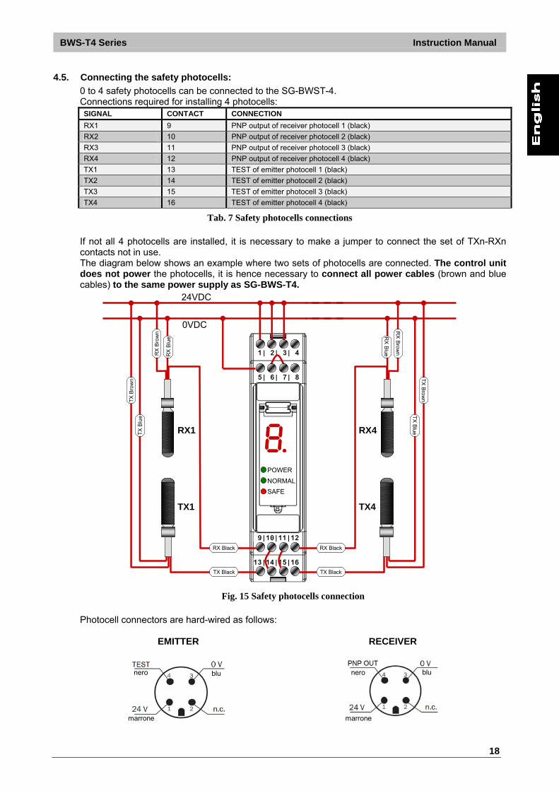
4.5. Connecting the safety photocells:
0 to 4 safety photocells can be connected to the SG-BWST-4. Connections required for installing 4 photocells: SIGNAL CONTACT CONNECTION
RX1 9 PNP output of receiver photocell 1 (black)
RX2 10 PNP output of receiver photocell 2 (black)
RX3 11 PNP output of receiver photocell 3 (black)
RX4 12 PNP output of receiver photocell 4 (black)
TX1 13 TEST of emitter photocell 1 (black)
TX2 14 TEST of emitter photocell 2 (black)
TX3 15 TEST of emitter photocell 3 (black)
TX4 16 TEST of emitter photocell 4 (black)
Tab. 7 Safety photocells connections
If not all 4 photocells are installed, it is necessary to make a jumper to connect the set of TXn-RXn contacts not in use. The diagram below shows an example where two sets of photocells are connected. The control unit does not power the photocells, it is hence necessary to connect all power cables (brown and blue cables) to the same power supply as SG-BWS-T4.
Power
Safe
Break
5| 6| 7| 8
1| 2| 3| 4
24VDC
0VDC
TX1
RX1
RX Black
TX Black
9|10|11|12
13|14|15|16
POWER
NORMAL
SAFE
POWER
NORMAL
SAFE
RX
Blu
e
RX
Bro
wn
TX
Blu
e
TX
Bro
wn
TX4
RX4
RX Black
TX Black
RX
Blue
RX
Brow
n
TX
Blue
TX
Bro
wn
Fig. 15 Safety photocells connection
Photocell connectors are hard-wired as follows:
EMITTER
nero
marrone
blu
RECEIVER
nero
marrone
blu
Instruction Manual BWS-T4 Series
19
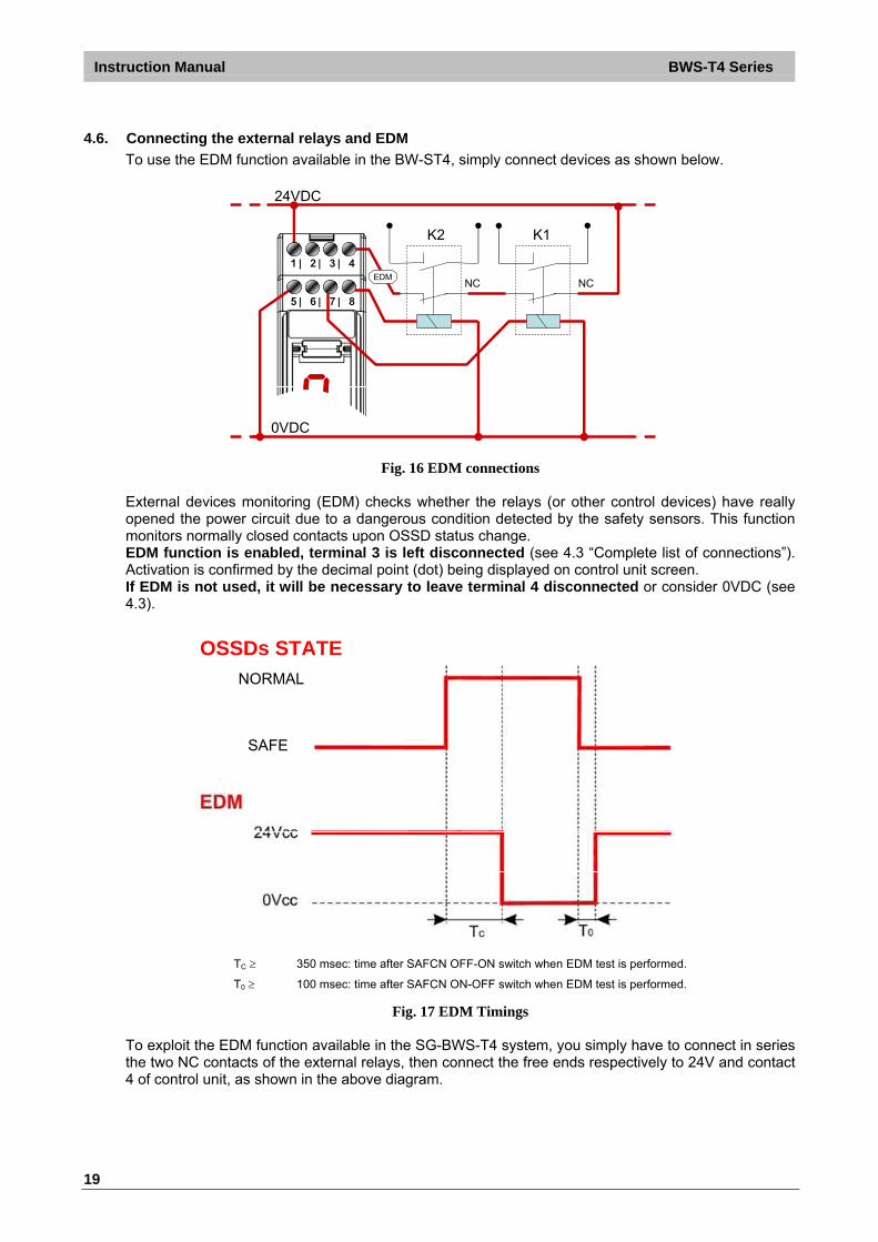
4.6. Connecting the external relays and EDM
To use the EDM function available in the BW-ST4, simply connect devices as shown below.
24VDC
K1K2
5| 6| 7| 8
1| 2| 3| 4
0VDC
NC NCEDM
Fig. 16 EDM connections External devices monitoring (EDM) checks whether the relays (or other control devices) have really opened the power circuit due to a dangerous condition detected by the safety sensors. This function monitors normally closed contacts upon OSSD status change. EDM function is enabled, terminal 3 is left disconnected (see 4.3 “Complete list of connections”). Activation is confirmed by the decimal point (dot) being displayed on control unit screen. If EDM is not used, it will be necessary to leave terminal 4 disconnected or consider 0VDC (see 4.3).
OSSDs STATE
NORMAL
SAFE
TC 350 msec: time after SAFCN OFF-ON switch when EDM test is performed.
T0 100 msec: time after SAFCN ON-OFF switch when EDM test is performed.
Fig. 17 EDM Timings To exploit the EDM function available in the SG-BWS-T4 system, you simply have to connect in series the two NC contacts of the external relays, then connect the free ends respectively to 24V and contact 4 of control unit, as shown in the above diagram.

BWS-T4 Series Instruction Manual
20
4.7. Reset mode and connection of the Start/Test/Reset push-button
The interruption of a beam due to an opaque object causes the opening of OSSD outputs and the stop of the safety control unit (SAFE condition, SAFE). ESPE standard operation can be reset (OSSD safety outputs closing, NORMAL OPERATION condition, NORMAL) in two different ways:
Automatic reset: After its activation ESPE resets to standard operating condition once the object has been removed from the controlled area.
Manual reset: After its activation, ESPE resets to standard operating condition only once the reset function has been enabled and provided that the object has been removed from the controlled area. This condition determines interlock status, pointed out on the display by the relevant warning (see section 6 “Diagnostics and warnings”). The reset command will only be effective if button is held for over 0.5s but less than 5s. Automatic or manual reset mode is selected by duly connecting terminal 6 (see 4.3 “Complete list of connections”).
Carefully assess risk conditions and reset modes. In applications protecting access to dangerous areas, the automatic reset mode is potentially unsafe if it allows the operator to pass completely beyond the sensitive area. In this case, manual resetting is required.
5| 6| 7| 8
1| 2| 3| 4
Start/Test/Reset
24VDC
0VDC
Fig. 18 Start/Test/Reset button connection
Reset control shall be output by a suitable push-button with NC contact towards 24VDC, as shown in the above diagram. The START signal is active low.
Carefully spot the most suitable position for the reset push-button! Install the reset push-button outside the dangerous area so as it is not possible to activate it from inside the area. The operator shall always be able to see the whole dangerous area whenever activating the reset push-button.
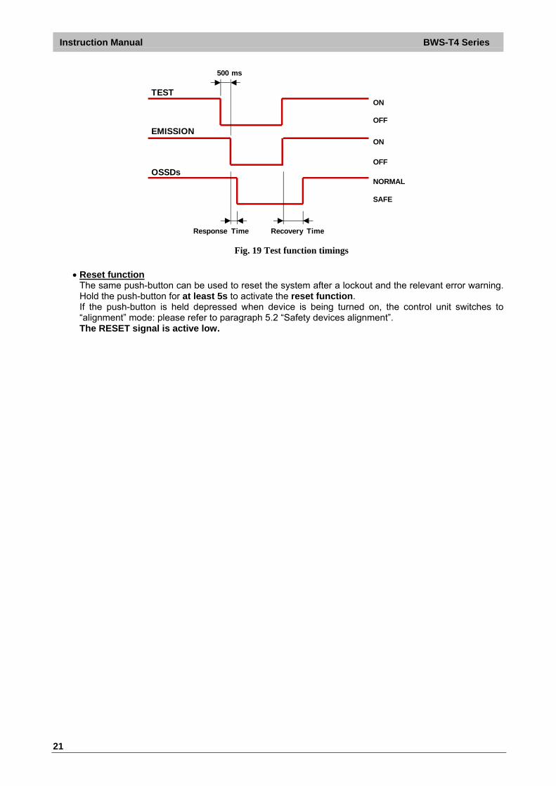
Test function
The Test command temporarily disables beam emission in order to check switching to SAFE status. This function can be activated by opening (for at least 0.5 seconds) an NC outer contact (START/TEST/RESET push-button). The TEST signal is active low. When this function is activated, ESPE switches to SAFE status and displays the relevant warning (see section 6 “Diagnostics and warnings”).
Instruction Manual BWS-T4 Series
21
TEST
EMISSION
OSSDs
ON
OFF
ON
OFF
NORMAL
SAFE
500 ms
Response Time Recovery Time Fig. 19 Test function timings
Reset function
The same push-button can be used to reset the system after a lockout and the relevant error warning. Hold the push-button for at least 5s to activate the reset function. If the push-button is held depressed when device is being turned on, the control unit switches to “alignment” mode: please refer to paragraph 5.2 “Safety devices alignment”. The RESET signal is active low.

BWS-T4 Series Instruction Manual
22
5. COMMISSIONING
Before commissioning a system protected by SG-BWS-T4 it shall be inspected and checked by a qualified technician who shall state its suitability. Please refer, for further details on this subject, the instructions given under paragraph 3.1 “Safety information”.
5.1. Screen indications upon switch-on
As soon as control unit is powered, all 7 display segments will turn on. The display will then switch off and all segments are quickly activated one after the other. The display will then switch off again meaning that the device is ready for use. When the display does not switch off, there is an error in the device (see section 6 “Diagnostics and warnings”). The meaning of displayed values is as follows:
Display Meaning
7-segment display test routine. All segments are activated one after the other.
Nothing on screen (only decimal point if EDM on)
The device is ready for use
Any other view System failure. Refer to section 6 “Diagnostics and warnings”
Tab. 8 Startup visualization sequence
5.2. Safety devices alignment
Once all components are in place and connected, emitters and receivers shall be mutually aligned. In alignment mode, the SAFCN safety outputs are open. The alignment mode and relevant procedure are described here below:
Cut off control unit power supply. Hold the Test push-button depressed (open Test contact). Power on the control unit. The 7-segment display shows the first device to be aligned (Photocells 1-4, light curtains 5-6) Align the indicated device until display will indicate the following device to be aligned or alignment
completed warning ( flashing). When alignment is completed, cut off control unit power, release Test push-button (close the contact) and restore control unit power. The control unit will run the initial test routines and display a countdown, the display will then turn off and the control unit will switch to NORMAL OPERATION status ( NORMAL). Now carry out the following inspections:
The ESPE stays in SAFE mode during photocells and light curtains beam interruption using the suitable “Test Piece”, along the entire protected area.
Enabling the TEST function, the SAFCN outputs should open (SAFE and the controlled machine stops).
The response time upon machine STOP (including response time of the ESPE and of the machine) is within the limits defined for the calculation of the safety distance (see section 3 “Installation”).
The safety distance between the dangerous areas and the safety sensors is in accordance with the instructions included in section 3 “Installation”.
Access of a person between sensors and machine dangerous parts is not possible nor is it possible for him/her to stay there.
Access to the dangerous area of the machine from any unprotected area is not possible. During alignment or normal operation, make sure that the photocells connected to the same or other units do not interfere with each other. Should you find interference, change their position, for instance you could set some emitter sets on the side of the other receivers. In case of interference, the control unit will lock out and display the relevant error code.

Instruction Manual BWS-T4 Series
23
6. DIAGNOSTICS AND WARNINGS SG-BWS-T4 is equipped with a user interface featuring 3 LEDs and a 7-segment display.
LED Indication Power Device is powered correctly
NORMAL No danger: safety outputs closed
SAFE Danger or fault: safety outputs open
The 7-segment display shows detailed information on control unit current status
Tab. 9 Signalling interface
6.1. Normal operation signalling
The table below specifies all possible screen indications and the system status or failure associated to each of them.
INDICATION STATUS DESCRIPTION TO DO POWER NORMAL SAFE
Alignment The display shows the first device to be aligned and then the others in a sequence (1 to 4).
Align the safety devices (see 5.2)
POWER NORMAL SAFE
Alignment All connected devices are aligned Close the Test contact (Pin 2) and restart the control unit to switch to normal operation (see 5.2)
POWER NORMAL SAFE
SAFE The indicated safety device beam is interrupted. If many devices are in this status, the first one is indicated, then the others in a sequence (1 to 4).
Clear the area or check device connections
POWER NORMAL SAFE
NORMAL OPERATION
The device is in normal operating conditions and monitored area is safe.
POWER NORMAL SAFE
Interlock Waiting for the START command in manual reset mode
Push reset control
POWER / NORMAL / SAFE
NORMAL OPERATION/
SAFE
The decimal point indicates that the EDM function is active (see 4.7)
POWER NORMAL SAFE
SAFE TEST push-button pressed (contact 2 open)
Check TEST push-button connections (see 4.6)
Tab. 10 Normal operation signalling
BWS-T4 Series Instruction Manual
24
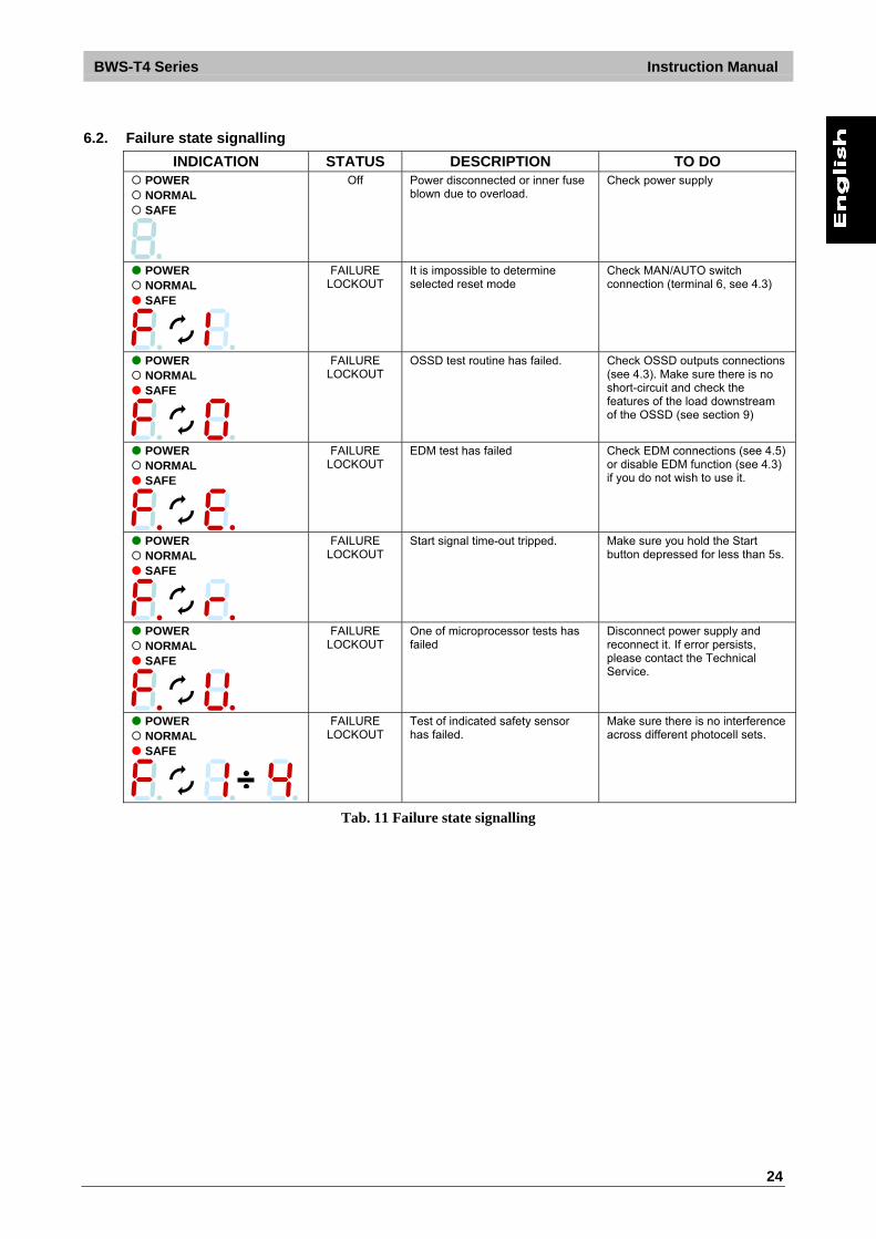
6.2. Failure state signalling
INDICATION STATUS DESCRIPTION TO DO POWER NORMAL SAFE
Off Power disconnected or inner fuse blown due to overload.
Check power supply
POWER NORMAL SAFE
FAILURE LOCKOUT
It is impossible to determine selected reset mode
Check MAN/AUTO switch connection (terminal 6, see 4.3)
POWER NORMAL SAFE
FAILURE LOCKOUT
OSSD test routine has failed. Check OSSD outputs connections (see 4.3). Make sure there is no short-circuit and check the features of the load downstream of the OSSD (see section 9)
POWER NORMAL SAFE
FAILURE LOCKOUT
EDM test has failed Check EDM connections (see 4.5) or disable EDM function (see 4.3) if you do not wish to use it.
POWER NORMAL SAFE
FAILURE LOCKOUT
Start signal time-out tripped. Make sure you hold the Start button depressed for less than 5s.
POWER NORMAL SAFE
FAILURE LOCKOUT
One of microprocessor tests has failed
Disconnect power supply and reconnect it. If error persists, please contact the Technical Service.
POWER NORMAL SAFE
FAILURE LOCKOUT
Test of indicated safety sensor has failed.
Make sure there is no interference across different photocell sets.
Tab. 11 Failure state signalling

Instruction Manual BWS-T4 Series
25
7. PERIODICAL CHECKS AND WARRANTY
7.1. Periodical checks
The following is a list of recommended check and maintenance operations that should be periodically carried out by qualified personnel. Check that: The ESPE stays in OSSD disabled state ( SAFE) mode during photocells beam interruption using the suitable “Test Piece”, along the entire protected area.
Sensors are correctly aligned: by slightly pressing each sensor side, in both directions, the system shall stay in NORMAL mode
Enabling the TEST function, the SAFCN outputs should open ( SAFE and the controlled machine stops).
The response time upon machine STOP (including response time of the ESPE and of the machine) is within the limits defined for the calculation of the safety distance (see section 3 “Installation”).
The safety distance between the dangerous areas and the safety sensors is in accordance with the instructions included in section 3 “Installation”.
Access of a person between sensors and machine dangerous parts is not possible nor is it possible for him/her to stay there.
Access to the dangerous area of the machine from any unprotected area is not possible. The ESPE, the sensors and the external electrical connections are not damaged. The frequency of checks depends on the particular application and on the operating conditions of the
safety light curtain.
7.2. Warranty
Datalogic Automation guarantees each brand new SG-BWS-T4 system, under standard use conditions, against manufacturing defects in material and workmanship for a period of 36 (thirty-six) months from the date of manufacturing. Datalogic Automation will not be liable for any damages to persons and things caused by failure to stick to the correct installation modes and device use. Warranty validity is subjected to the following conditions:
User shall notify Datalogic Automation the failure within thirty-six months from product manufacturing date.
Failure or malfunction shall not have been originated directly or indirectly by: o Use for unsuitable purposes; o Failure to comply with the intended use prescriptions; o Negligence, unskillfulness, wrong maintenance; o Repairing, changes, adaptations not made by Datalogic Automation personnel, tampering
with the device, etc.; o Accidents or crashes (even due to transportation or by force majeure causes); o Other causes not depending from Datalogic Automation.
If the device does not work, send the unit to Datalogic Automation The Customer is responsible for all transport charges and damage risks or material loss during transport, unless otherwise agreed. All replaced products and parts become a property of Datalogic Automation. Datalogic Automation acknowledges no other guarantees or rights apart from the ones expressly specified above. Therefore no claims for damages due to afforded costs, suspension of working activities or other factors somehow linked with product or product parts failure will be accepted. In case of problems, please contact Datalogic Automation Service Department.
Service Department Phone no.: +39 051 6765611 Fax no.: +39 051 6759324

BWS-T4 Series Instruction Manual
26
8. DEVICE MAINTENANCE SG-BWS-T4 and photocells of the S5, SL5, S300 series do not require any special servicing. To avoid the reduction of the operative distance, optics protective front surfaces shall be cleaned at regular intervals. To this end, use soft cotton cloths damped in water; do not apply too much pressure onto the surface so as not to make it dull. Please do not use on plastic surfaces or optics:
alcohol or solvents wool or synthetic cloths paper or other abrasive materials
8.1. Product disposal
Under current Italian and European laws, Datalogic Automation is not obliged to take care of product disposal at the end of its useful life. Datalogic Automation recommends to dispose of the product in compliance with local laws or contact authorised waste collection centres.
Instruction Manual BWS-T4 Series
27
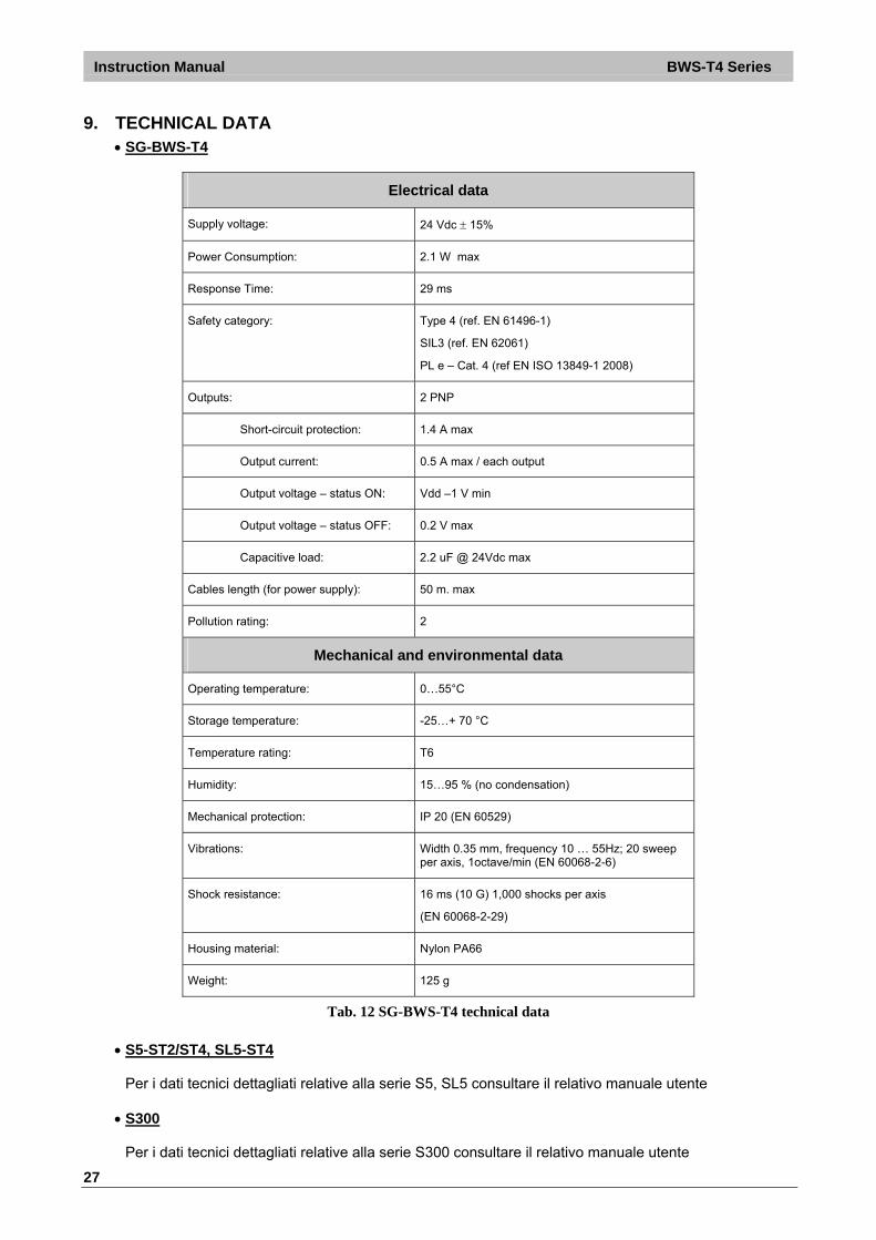
9. TECHNICAL DATA SG-BWS-T4
Electrical data
Supply voltage: 24 Vdc 15%
Power Consumption: 2.1 W max
Response Time: 29 ms
Safety category: Type 4 (ref. EN 61496-1)
SIL3 (ref. EN 62061)
PL e – Cat. 4 (ref EN ISO 13849-1 2008)
Outputs: 2 PNP
Short-circuit protection: 1.4 A max
Output current: 0.5 A max / each output
Output voltage – status ON: Vdd –1 V min
Output voltage – status OFF: 0.2 V max
Capacitive load: 2.2 uF @ 24Vdc max
Cables length (for power supply): 50 m. max
Pollution rating: 2
Mechanical and environmental data
Operating temperature: 0…55°C
Storage temperature: -25…+ 70 °C
Temperature rating: T6
Humidity: 15…95 % (no condensation)
Mechanical protection: IP 20 (EN 60529)
Vibrations: Width 0.35 mm, frequency 10 … 55Hz; 20 sweep per axis, 1octave/min (EN 60068-2-6)
Shock resistance: 16 ms (10 G) 1,000 shocks per axis
(EN 60068-2-29)
Housing material: Nylon PA66
Weight: 125 g
Tab. 12 SG-BWS-T4 technical data
S5-ST2/ST4, SL5-ST4
Per i dati tecnici dettagliati relative alla serie S5, SL5 consultare il relativo manuale utente
S300
Per i dati tecnici dettagliati relative alla serie S300 consultare il relativo manuale utente
BWS-T4 Series Instruction Manual
28
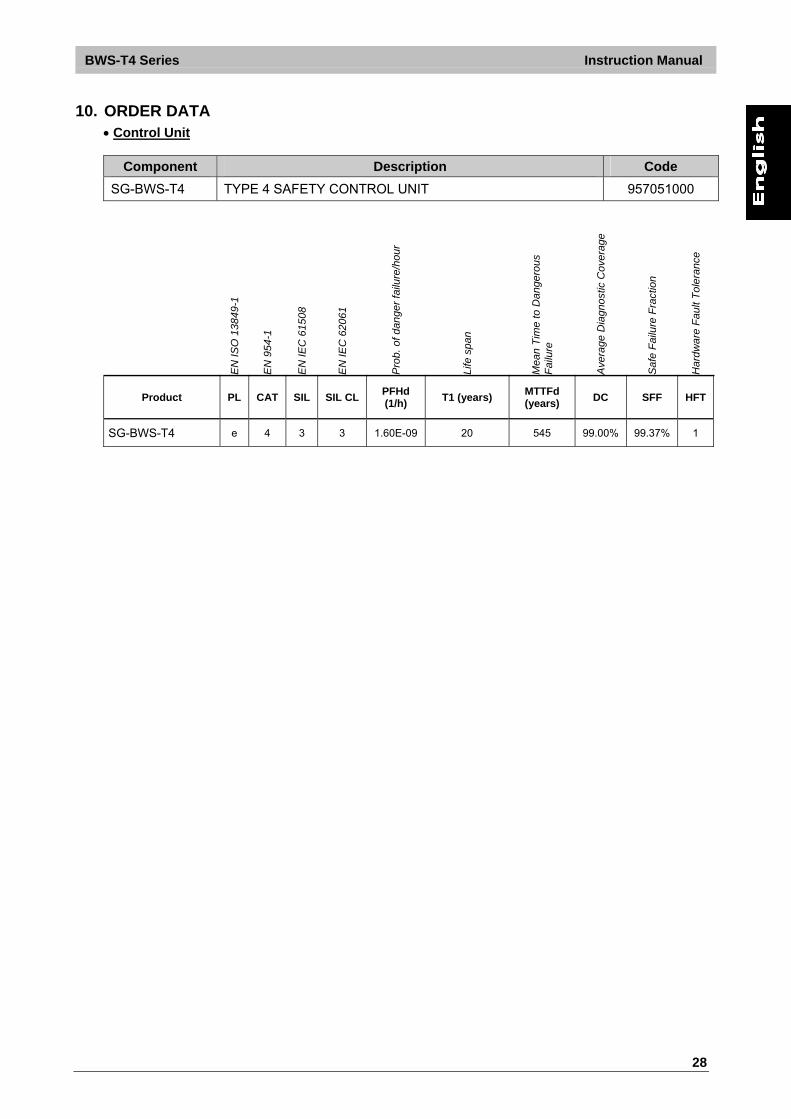
10. ORDER DATA Control Unit
Component Description Code
SG-BWS-T4 TYPE 4 SAFETY CONTROL UNIT 957051000
EN
ISO
138
49-1
EN
954
-1
EN
IEC
615
08
EN
IEC
620
61
Pro
b. o
f dan
ger
failu
re/h
our
Life
spa
n
Mea
n T
ime
to D
ang
erou
s F
ailu
re
Ave
rage
Dia
gnos
tic C
over
age
Saf
e F
ailu
re F
ract
ion
Har
dwa
re F
ault
Tol
eran
ce
Product PL CAT SIL SIL CL PFHd (1/h)
T1 (years) MTTFd (years)
DC SFF HFT
SG-BWS-T4 e 4 3 3 1.60E-09 20 545 99.00% 99.37% 1
Instruction Manual BWS-T4 Series
29
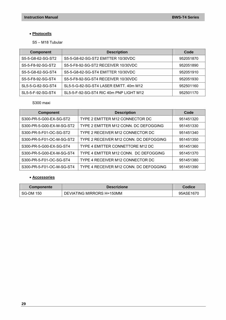
Photocells
S5 – M18 Tubular
Component Description Code
S5-5-G8-62-SG-ST2 S5-5-G8-62-SG-ST2 EMITTER 10/30VDC 952051870
S5-5-F8-92-SG-ST2 S5-5-F8-92-SG-ST2 RECEIVER 10/30VDC 952051890
S5-5-G8-62-SG-ST4 S5-5-G8-62-SG-ST4 EMITTER 10/30VDC 952051910
S5-5-F8-92-SG-ST4 S5-5-F8-92-SG-ST4 RECEIVER 10/30VDC 952051930
SL5-5-G-82-SG-ST4 SL5-5-G-82-SG-ST4 LASER EMITT. 40m M12 952501160
SL5-5-F-92-SG-ST4 SL5-5-F-92-SG-ST4 RIC 40m PNP LIGHT M12 952501170
S300 maxi
Component Description Code
S300-PR-5-G00-EX-SG-ST2 TYPE 2 EMITTER M12 CONNECTOR DC 951451320
S300-PR-5-G00-EX-M-SG-ST2 TYPE 2 EMITTER M12 CONN. DC DEFOGGING 951451330
S300-PR-5-F01-OC-SG-ST2 TYPE 2 RECEIVER M12 CONNECTOR DC 951451340
S300-PR-5-F01-OC-M-SG-ST2 TYPE 2 RECEIVER M12 CONN. DC DEFOGGING 951451350
S300-PR-5-G00-EX-SG-ST4 TYPE 4 EMITTER CONNETTORE M12 DC 951451360
S300-PR-5-G00-EX-M-SG-ST4 TYPE 4 EMITTER M12 CONN. DC DEFOGGING 951451370
S300-PR-5-F01-OC-SG-ST4 TYPE 4 RECEIVER M12 CONNECTOR DC 951451380
S300-PR-5-F01-OC-M-SG-ST4 TYPE 4 RECEIVER M12 CONN. DC DEFOGGING 951451390
Accessories
Componente Descrizione Codice
SG-DM 150 DEVIATING MIRRORS H=150MM 95ASE1670

BWS-T4 Series Instruction Manual
30
11. OVERALL DIMENSIONS
11.1. SG-BWS-T4
Fig. 20 SG-BWS-T4 Overall dimensions
11.2. S5-ST2,S5-ST4, SL5-ST4, S300
For overall dimensions of single beam photocells see the relative user manuals.
Instruction Manual BWS-T4 Series
31
12. APPENDIX
12.1. FIGURE INDEX:
Fig. 1 SG-BWS-T4-MT Appearance and user interface ......................................................................... 6 Fig. 2 Safety single beam photocells S5,SL5 series (appearance) ........................................................ 7 Fig. 3 Automatic warehouses protection with photocells ........................................................................ 8 Fig. 4 Doors control by means of safety photocelss ............................................................................... 8 Fig. 5 Safety Distance ........................................................................................................................... 10 Fig. 6 Photocells installation heights for 4 beams protections .............................................................. 11 Fig. 7 Distance from reflecting surfaces................................................................................................ 11 Fig. 8 Sensors disposal in order to avoid interferences ........................................................................ 12 Fig. 9 Distance between equal sensors ................................................................................................ 13 Fig. 10 Safety Control Unit mounting .................................................................................................... 13 Fig. 11 Deviating Mirros ........................................................................................................................ 14 Fig. 12 External Relay Connection........................................................................................................ 15 Fig. 13 Minimum connection for function test........................................................................................ 16 Fig. 14 Connection clamps disposal ..................................................................................................... 17 Fig. 15 Safety photocells connection .................................................................................................... 18 Fig. 16 EDM connections ...................................................................................................................... 19 Fig. 17 EDM Timings............................................................................................................................. 19 Fig. 18 Start/Test/Reset button connection........................................................................................... 20 Fig. 19 Test function timings ................................................................................................................. 21 Fig. 20 SG-BWS-T4 Overall dimensions............................................................................................... 30
12.2. TABLES INDEX:
Tab. 1 User manual main contents ......................................................................................................... 5 Tab. 2 Signalling LEDs............................................................................................................................ 7 Tab. 3 Photocells signalling..................................................................................................................... 7 Tab. 4 Beams height for photocells protections .................................................................................... 10 Tab. 5 Minimum connection details for function test ............................................................................. 16 Tab. 6 Full connection list...................................................................................................................... 17 Tab. 7 Safety photocells connections ................................................................................................... 18 Tab. 8 Startup visualization sequence .................................................................................................. 22 Tab. 9 Signalling interface..................................................................................................................... 23 Tab. 10 Normal operation signalling ..................................................................................................... 23 Tab. 11 Failure state signalling ............................................................................................................. 24 Tab. 12 SG-BWS-T4 technical data...................................................................................................... 27