Embed Size (px)
Citation preview

1 MIT EECS 6.837 – Matusik
Shading & Material Appearance
© ACM. All rights reserved. This content is excluded from our Creative Commonslicense. For more information, see http://ocw.mit.edu/help/faq-fair-use/.
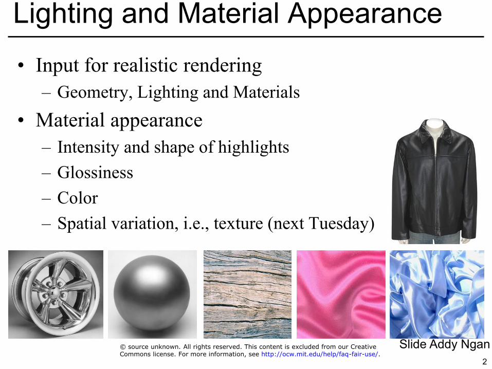
• Input for realistic rendering – Geometry, Lighting and Materials
• Material appearance – Intensity and shape of highlights – Glossiness – Color – Spatial variation, i.e., texture (next Tuesday)
2
Lighting and Material Appearance
Slide Addy Ngan © source unknown. All rights reserved. This content is excluded from our CreativeCommons license. For more information, see http://ocw.mit.edu/help/faq-fair-use/.
• We will not be too formal in this class • Issues we will not really care about
– Directional quantities vs. integrated over all directions – Differential terms: per solid angle, per area – Power? Intensity? Flux?
• Color
– All math here is for a single wavelength only; we will perform computations for R, G, B separately
• Do not panic, that just means we will perform every operation three times, that is all
3
Unit Issues - Radiometry
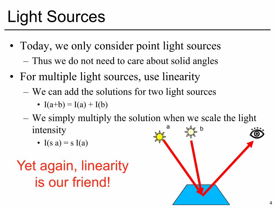
• Today, we only consider point light sources – Thus we do not need to care about solid angles
• For multiple light sources, use linearity – We can add the solutions for two light sources
• I(a+b) = I(a) + I(b)
– We simply multiply the solution when we scale the light intensity
• I(s a) = s I(a)
4
Light Sources
a b
Yet again, linearity is our friend!
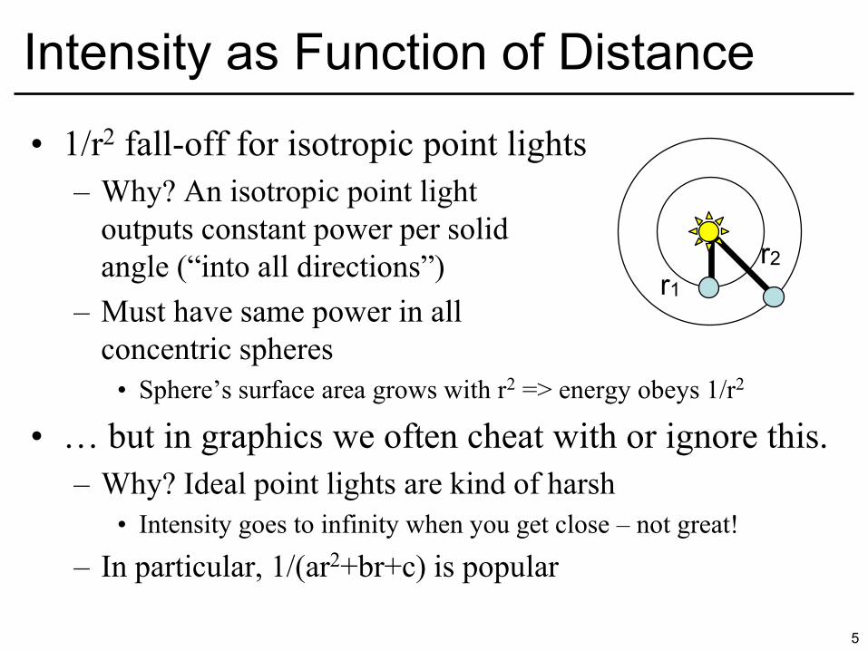
• 1/r2 fall-off for isotropic point lights – Why? An isotropic point light
outputs constant power per solid angle (“into all directions”)
– Must have same power in all concentric spheres
• Sphere’s surface area grows with r2 => energy obeys 1/r2
• … but in graphics we often cheat with or ignore this. – Why? Ideal point lights are kind of harsh
• Intensity goes to infinity when you get close – not great!
– In particular, 1/(ar2+br+c) is popular
5
Intensity as Function of Distance
r1
r2
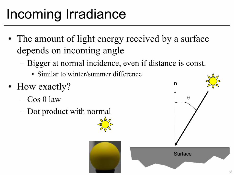
• The amount of light energy received by a surface depends on incoming angle – Bigger at normal incidence, even if distance is const.
• Similar to winter/summer difference
• How exactly? – Cos θ law – Dot product with normal
6
Incoming Irradiance
Surface
θ
n
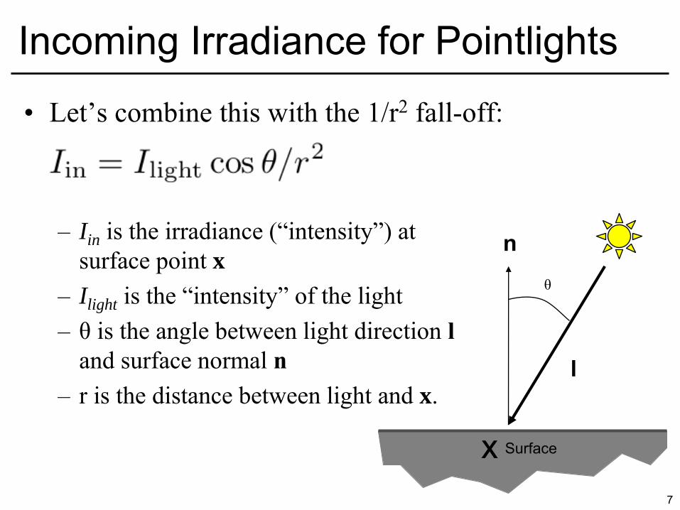
• Let’s combine this with the 1/r2 fall-off: – Iin is the irradiance (“intensity”) at
surface point x
– Ilight is the “intensity” of the light – θ is the angle between light direction l
and surface normal n – r is the distance between light and x.
7
Incoming Irradiance for Pointlights
Surface
θ
n
x
l
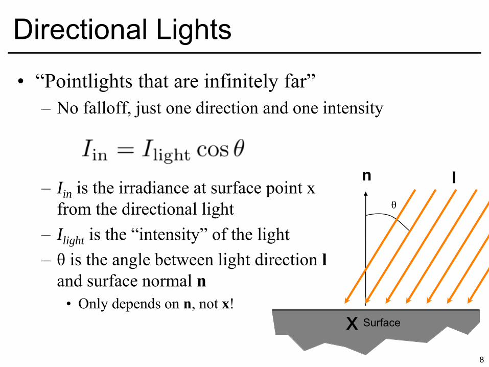
• “Pointlights that are infinitely far” – No falloff, just one direction and one intensity
– Iin is the irradiance at surface point x
from the directional light – Ilight is the “intensity” of the light – θ is the angle between light direction l
and surface normal n
• Only depends on n, not x!
8
Directional Lights
Surface
θ
n
x
l
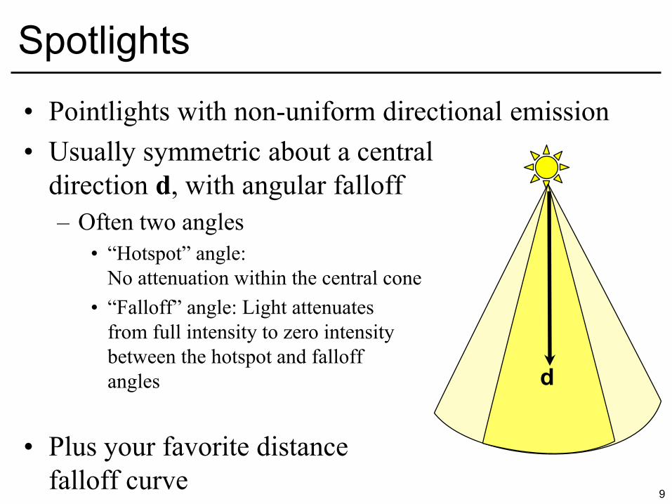
• Pointlights with non-uniform directional emission • Usually symmetric about a central
direction d, with angular falloff – Often two angles
• “Hotspot” angle: No attenuation within the central cone
• “Falloff” angle: Light attenuates from full intensity to zero intensity between the hotspot and falloff angles
• Plus your favorite distance falloff curve
9
Spotlights
d
10
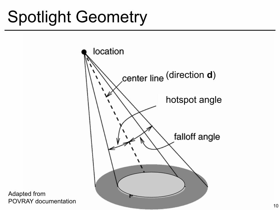
Spotlight Geometry
Adapted from POVRAY documentation
hotspot angle
(direction d)

11
Questions?
12
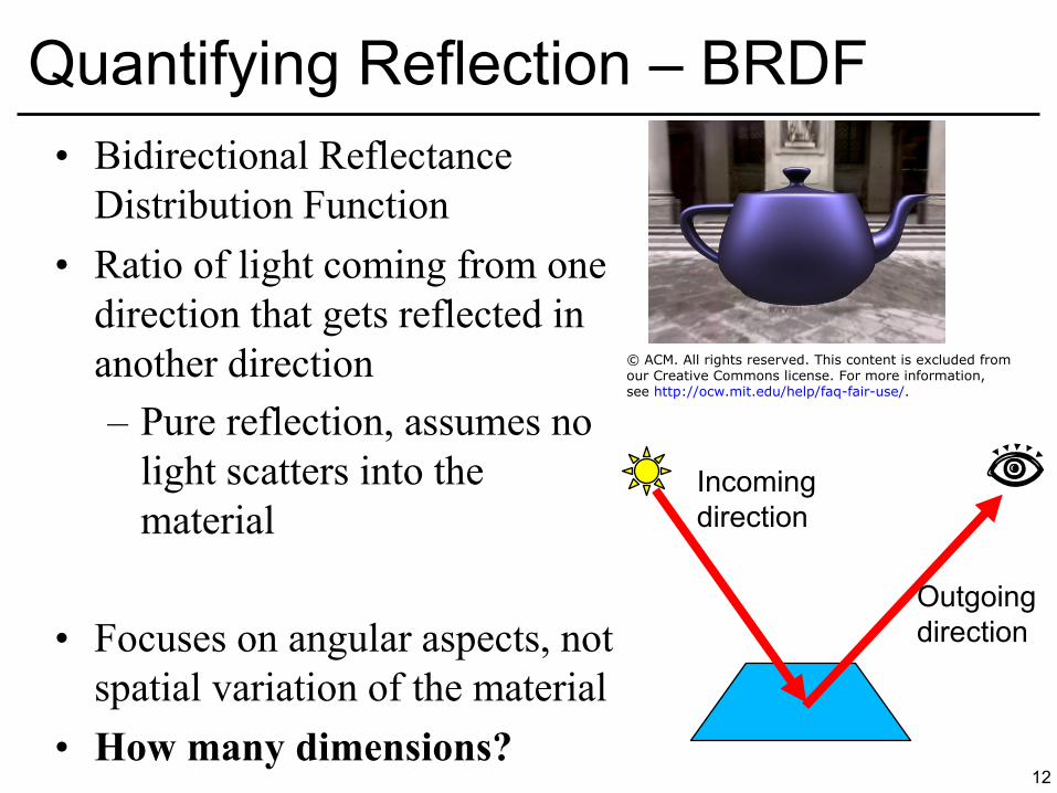
Quantifying Reflection – BRDF • Bidirectional Reflectance
Distribution Function • Ratio of light coming from one
direction that gets reflected in another direction – Pure reflection, assumes no
light scatters into the material
• Focuses on angular aspects, not spatial variation of the material
• How many dimensions?
Incoming direction
Outgoing direction
© ACM. All rights reserved. This content is excluded fromour Creative Commons license. For more information,see http://ocw.mit.edu/help/faq-fair-use/.
13
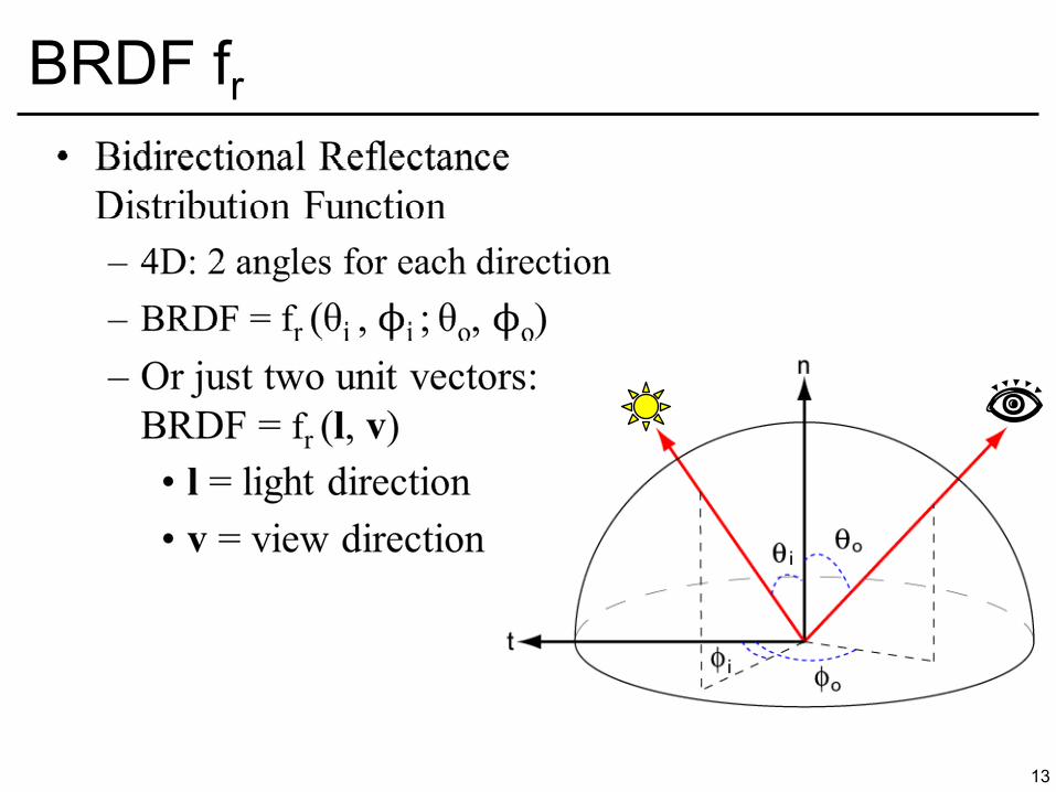
BRDF fr

14
BRDF fr
15
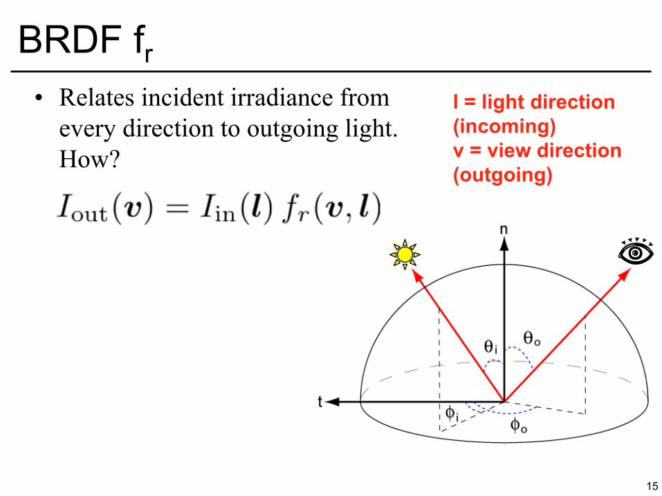
BRDF fr • Relates incident irradiance from
every direction to outgoing light. How?
l = light direction
(incoming)
v = view direction
(outgoing)
16
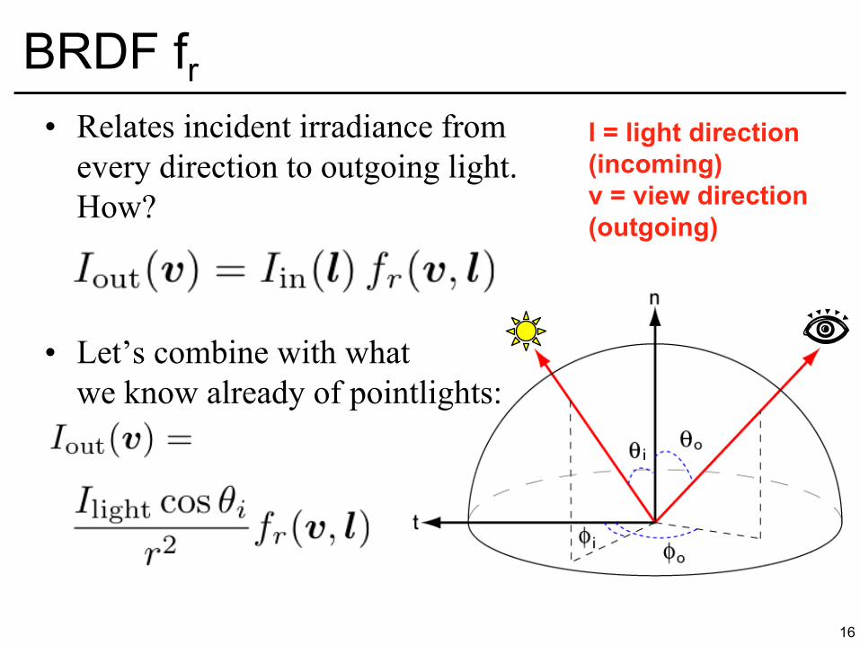
BRDF fr • Relates incident irradiance from
every direction to outgoing light. How?
• Let’s combine with what we know already of pointlights:
l = light direction
(incoming)
v = view direction
(outgoing)
17
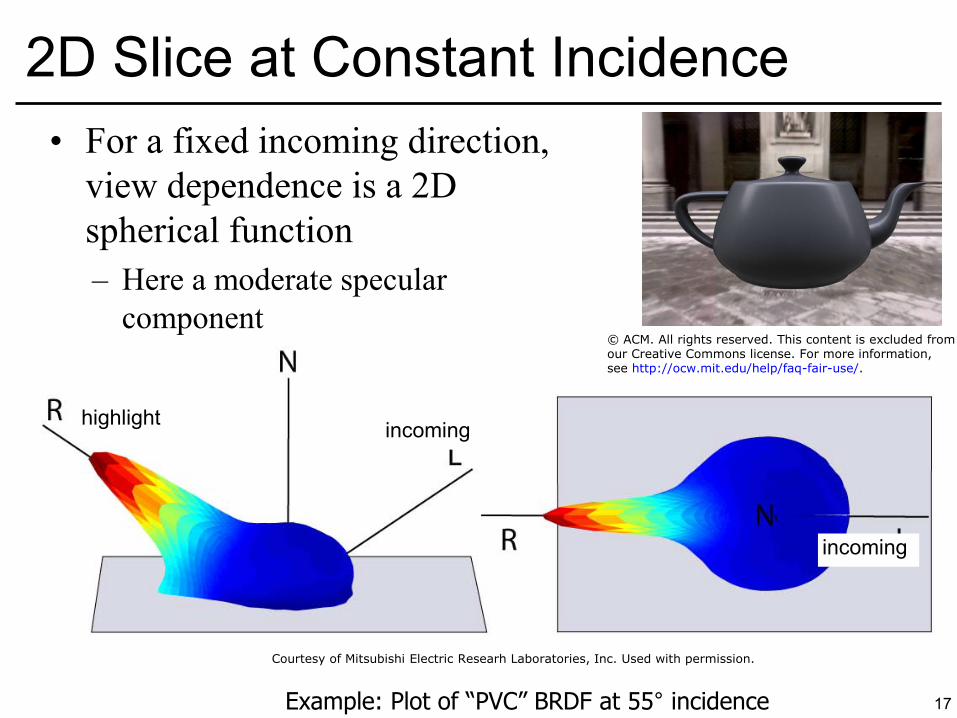
2D Slice at Constant Incidence
Example: Plot of “PVC” BRDF at 55° incidence
highlight incoming
incoming
• For a fixed incoming direction, view dependence is a 2D spherical function – Here a moderate specular
component
Courtesy of Mitsubishi Electric Researh Laboratories, Inc. Used with permission.
© ACM. All rights reserved. This content is excluded fromour Creative Commons license. For more information,see http://ocw.mit.edu/help/faq-fair-use/.

18
Demo
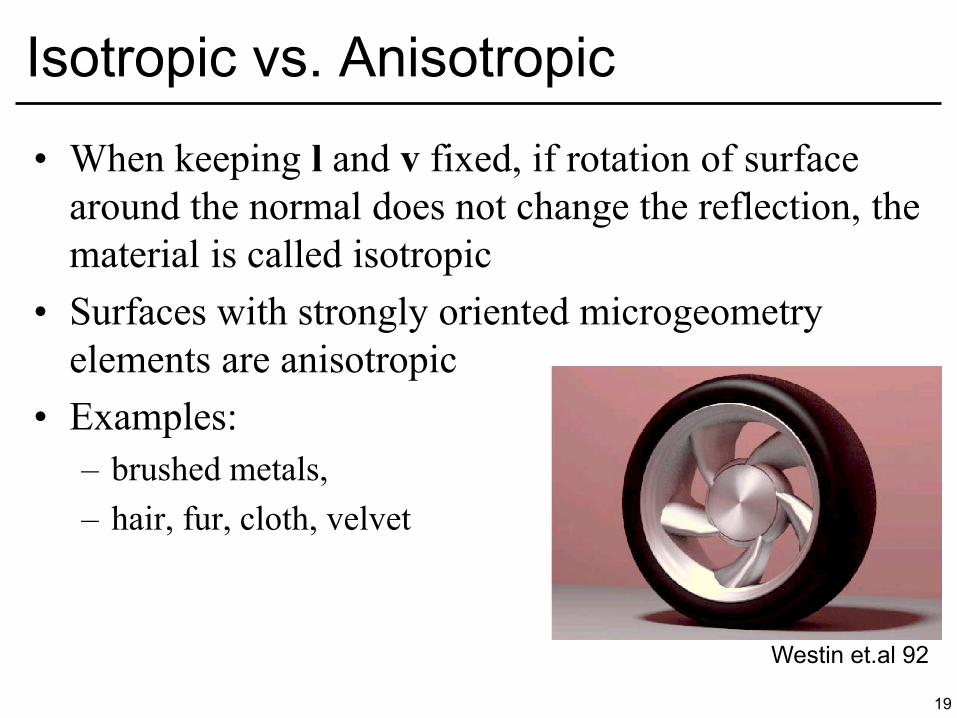
• When keeping l and v fixed, if rotation of surface around the normal does not change the reflection, the material is called isotropic
• Surfaces with strongly oriented microgeometry elements are anisotropic
• Examples: – brushed metals, – hair, fur, cloth, velvet
19
Isotropic vs. Anisotropic
Westin et.al 92

20
Demo

• One possibility: Gonioreflectometer – 4 degrees of freedom
21
How do we obtain BRDFs?
Source: Greg Ward © ACM. All rights reserved. This content is excluded from our Creative Commonslicense. For more information, see http://ocw.mit.edu/help/faq-fair-use/.
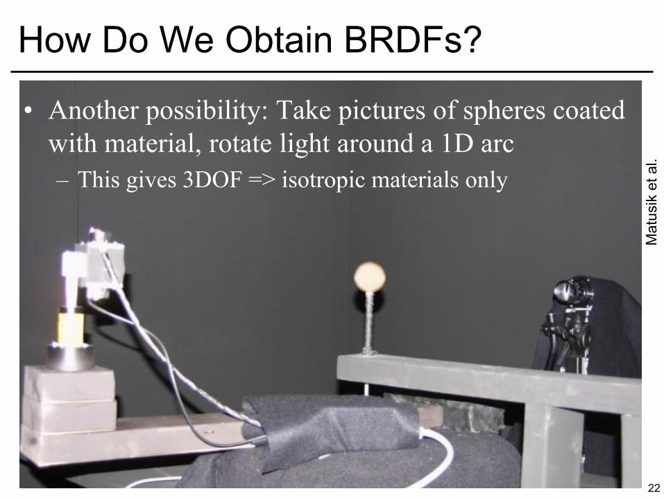
• Another possibility: Take pictures of spheres coated with material, rotate light around a 1D arc – This gives 3DOF => isotropic materials only
22
How Do We Obtain BRDFs?
Mat
usik
et a
l.
• BRDFs can be measured from real data – But tabulated 4D data is too cumbersome for most uses
• Therefore, parametric BRDF models represent the relationship between incident and outgoing light by some mathematical formula – The appearance can then be tuned by setting parameters
• “Shininess”, “anisotropy”, etc.
– Physically-based or Phenomenological – They can model with measured data (examples later)
• Popular models: Diffuse, Blinn-Phong, Cook-Torrance, Lafortune, Ward, Oren-Nayar, etc.
23
Parametric BRDFs

24
Questions?
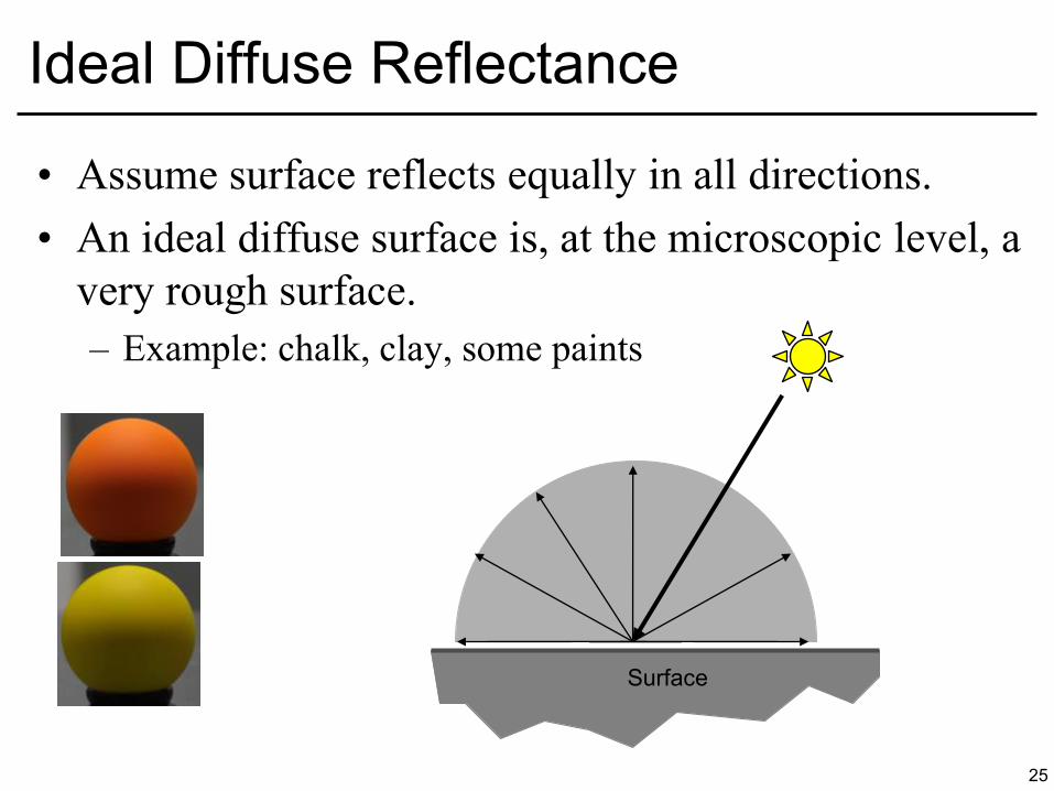
• Assume surface reflects equally in all directions. • An ideal diffuse surface is, at the microscopic level, a
very rough surface. – Example: chalk, clay, some paints
25
Ideal Diffuse Reflectance
Surface
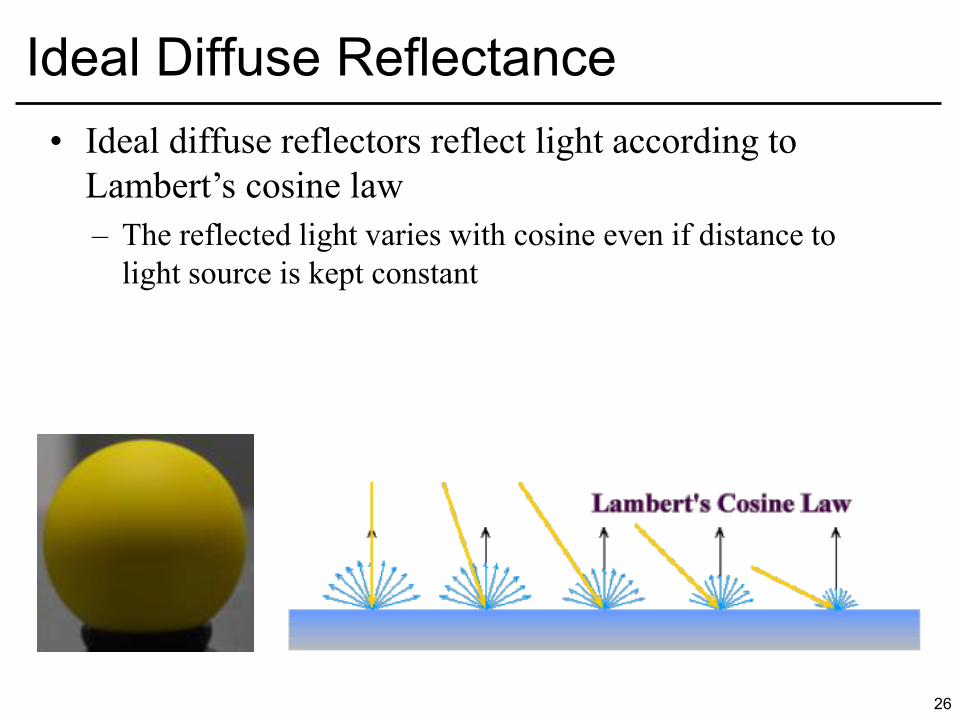
• Ideal diffuse reflectors reflect light according to Lambert’s cosine law – The reflected light varies with cosine even if distance to
light source is kept constant
26
Ideal Diffuse Reflectance
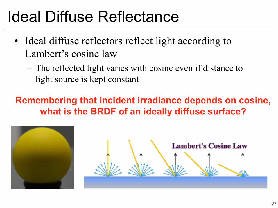
• Ideal diffuse reflectors reflect light according to Lambert’s cosine law – The reflected light varies with cosine even if distance to
light source is kept constant
27
Ideal Diffuse Reflectance
Remembering that incident irradiance depends on cosine,
what is the BRDF of an ideally diffuse surface?
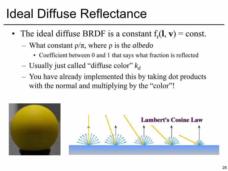
• The ideal diffuse BRDF is a constant fr(l, v) = const. – What constant ρ/π, where ρ is the albedo
• Coefficient between 0 and 1 that says what fraction is reflected
– Usually just called “diffuse color” kd
– You have already implemented this by taking dot products with the normal and multiplying by the “color”!
28
Ideal Diffuse Reflectance
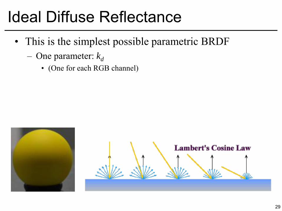
• This is the simplest possible parametric BRDF – One parameter: kd
• (One for each RGB channel)
29
Ideal Diffuse Reflectance
• Single Point Light Source – kd: diffuse coefficient (color) – n: Surface normal. – l: Light direction. – Li: Light intensity – r: Distance to source – Lo: Shaded color
30
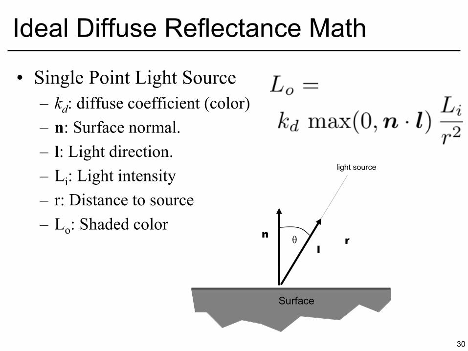
Ideal Diffuse Reflectance Math
Surface
θ l
n r
light source
• Single Point Light Source – kd: diffuse coefficient (color) – n: Surface normal. – l: Light direction. – Li: Light intensity – r: Distance to source – Lo: Shaded color
31
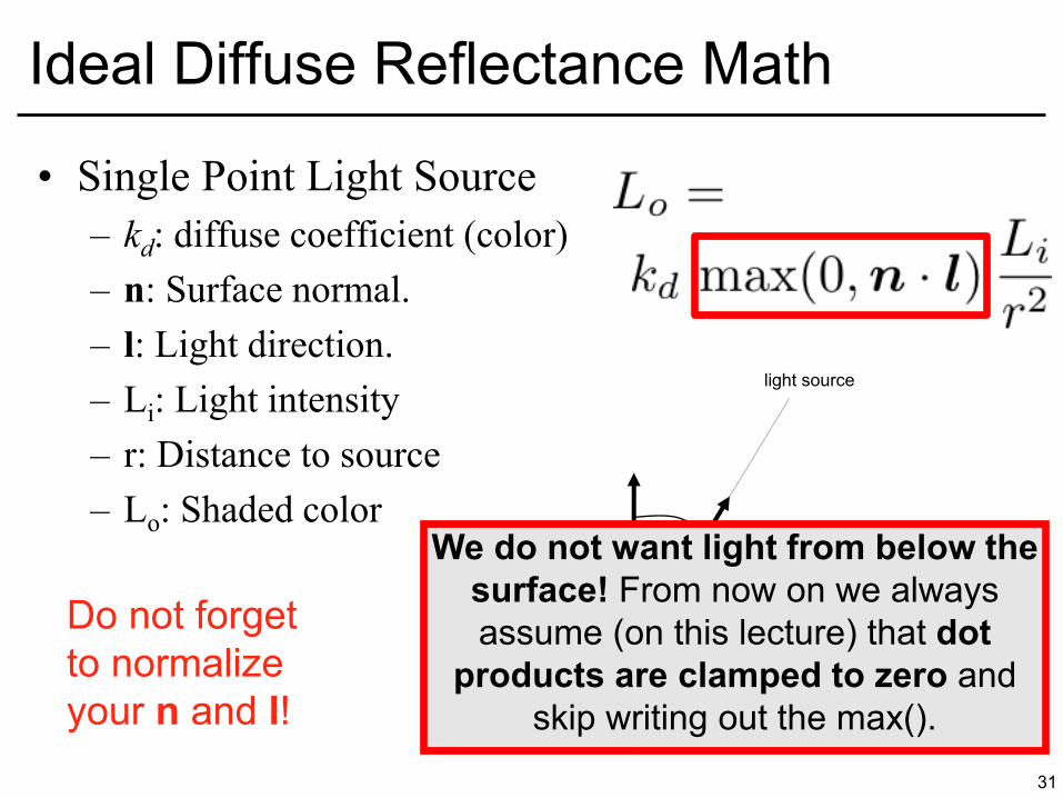
Ideal Diffuse Reflectance Math
Surface
l
n r We do not want light from below the
surface! From now on we always assume (on this lecture) that dot
products are clamped to zero and skip writing out the max().
Do not forget to normalize your n and l!
light source

32
Questions?
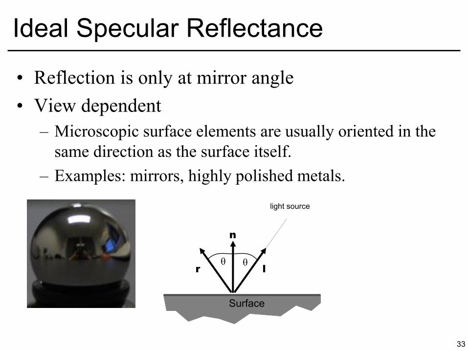
• Reflection is only at mirror angle • View dependent
– Microscopic surface elements are usually oriented in the same direction as the surface itself.
– Examples: mirrors, highly polished metals.
33
Ideal Specular Reflectance
Surface
θ l
n
r
θ
light source
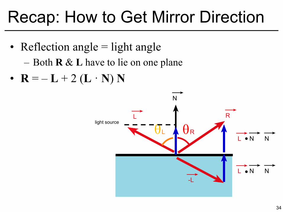
• Reflection angle = light angle – Both R & L have to lie on one plane
• R = – L + 2 (L · N) N
34
Recap: How to Get Mirror Direction
R L
θ L θ R
N
L N N
L N N
-L
light source
• Light only reflects to the mirror direction • A Dirac delta multiplied by a specular coefficient ks
• Not very useful for point lights, only for reflections
of other surfaces – Why? You cannot really see a mirror reflection of an
infinitely small light!
35
Ideal Specular BRDF
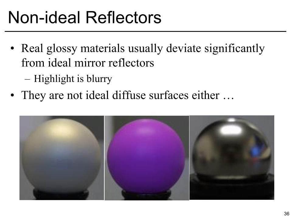
• Real glossy materials usually deviate significantly from ideal mirror reflectors – Highlight is blurry
• They are not ideal diffuse surfaces either …
36
Non-ideal Reflectors

• Simple Empirical Reasoning for Glossy Materials – We expect most of the reflected light to travel in the
direction of the ideal mirror ray. – However, because of microscopic surface variations we
might expect some of the light to be reflected just slightly offset from the ideal reflected ray.
– As we move farther and farther, in the angular sense, from the reflected ray, we expect to see less light reflected.
37
Non-ideal Reflectors
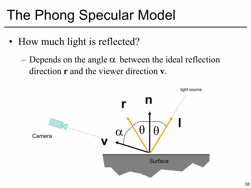
• How much light is reflected?
– Depends on the angle between the ideal reflection direction r and the viewer direction v.
38
The Phong Specular Model
Surface
θ θ Camera
r n
l
v
light source
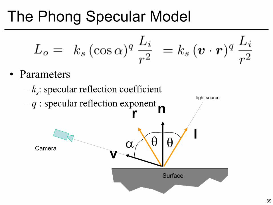
• Parameters – ks: specular reflection coefficient – q : specular reflection exponent
39
The Phong Specular Model
Surface
θ θ Camera
r n
l
v
light source
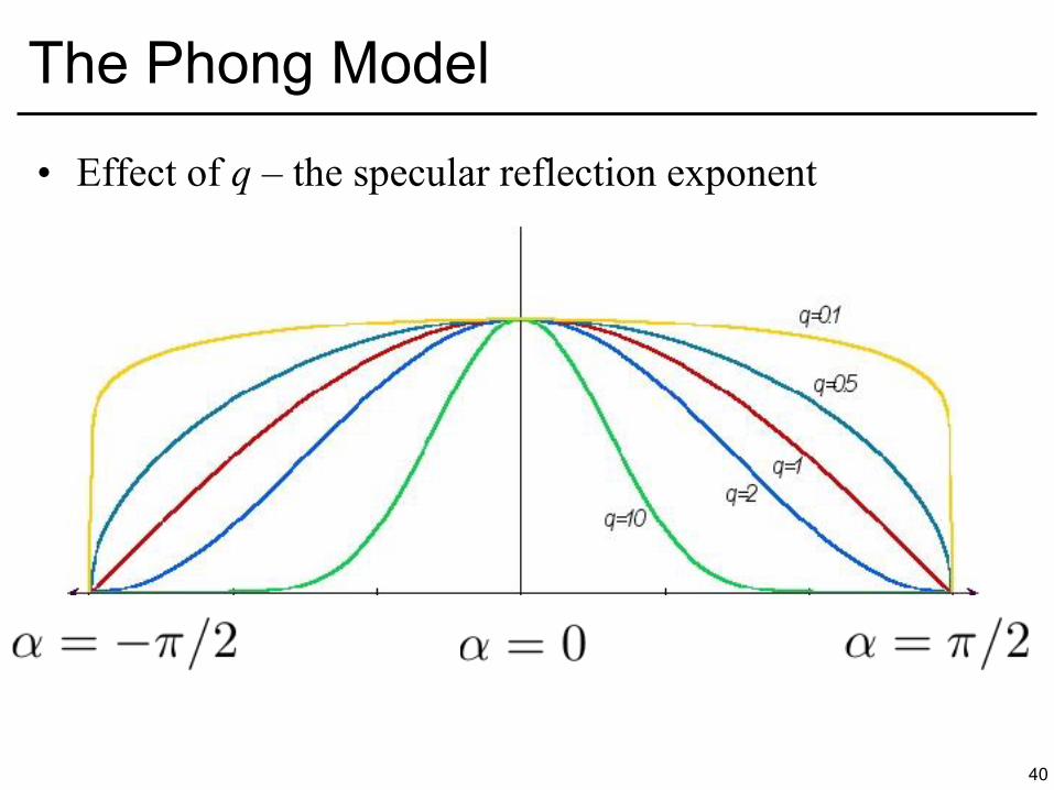
• Effect of q – the specular reflection exponent
40
The Phong Model
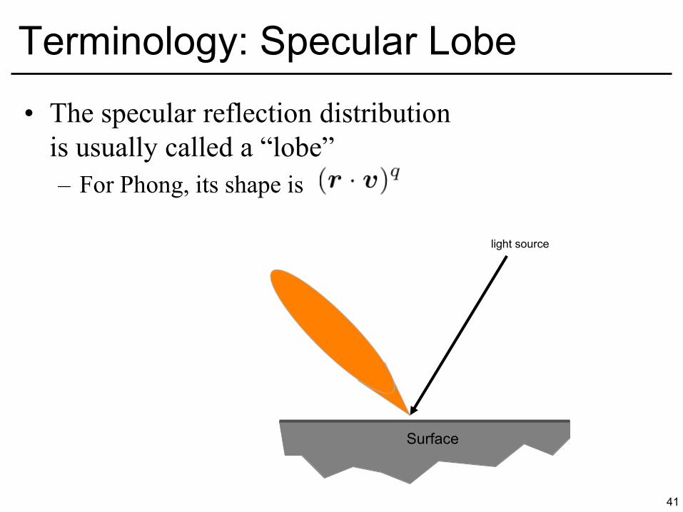
• The specular reflection distribution is usually called a “lobe” – For Phong, its shape is
41
Terminology: Specular Lobe
Surface
light source
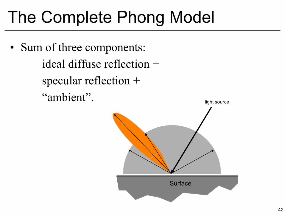
• Sum of three components: ideal diffuse reflection + specular reflection + “ambient”.
42
The Complete Phong Model
Surface
light source
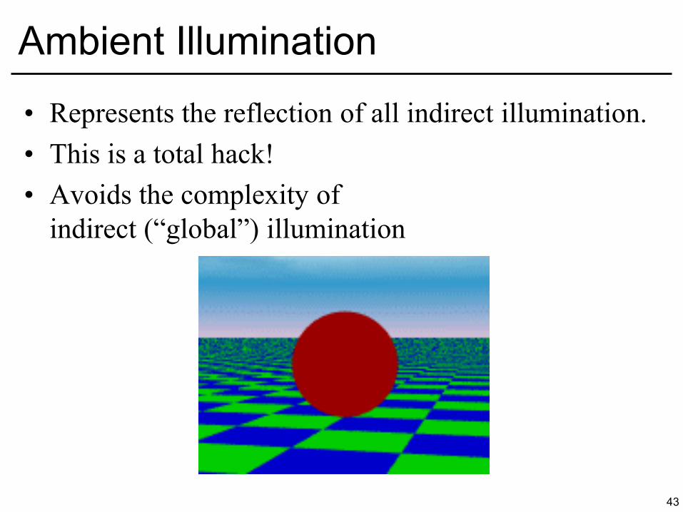
• Represents the reflection of all indirect illumination. • This is a total hack! • Avoids the complexity of
indirect (“global”) illumination
43
Ambient Illumination
• Phong Illumination Model
44
Putting It All Together
© Leonard McMillan. All rights reserved. This content is excluded from our CreativeCommons license. For more information, see http://ocw.mit.edu/help/faq-fair-use/.
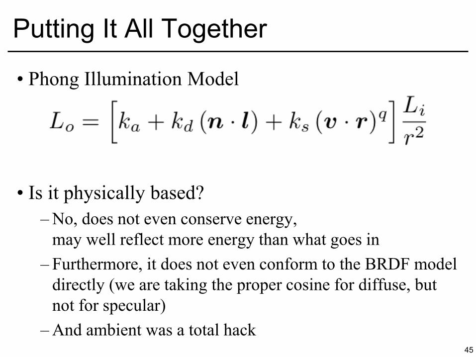
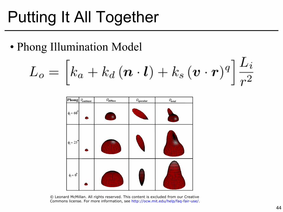
• Phong Illumination Model
• Is it physically based? – No, does not even conserve energy,
may well reflect more energy than what goes in – Furthermore, it does not even conform to the BRDF model
directly (we are taking the proper cosine for diffuse, but not for specular)
– And ambient was a total hack 45
Putting It All Together
46
Phong Examples
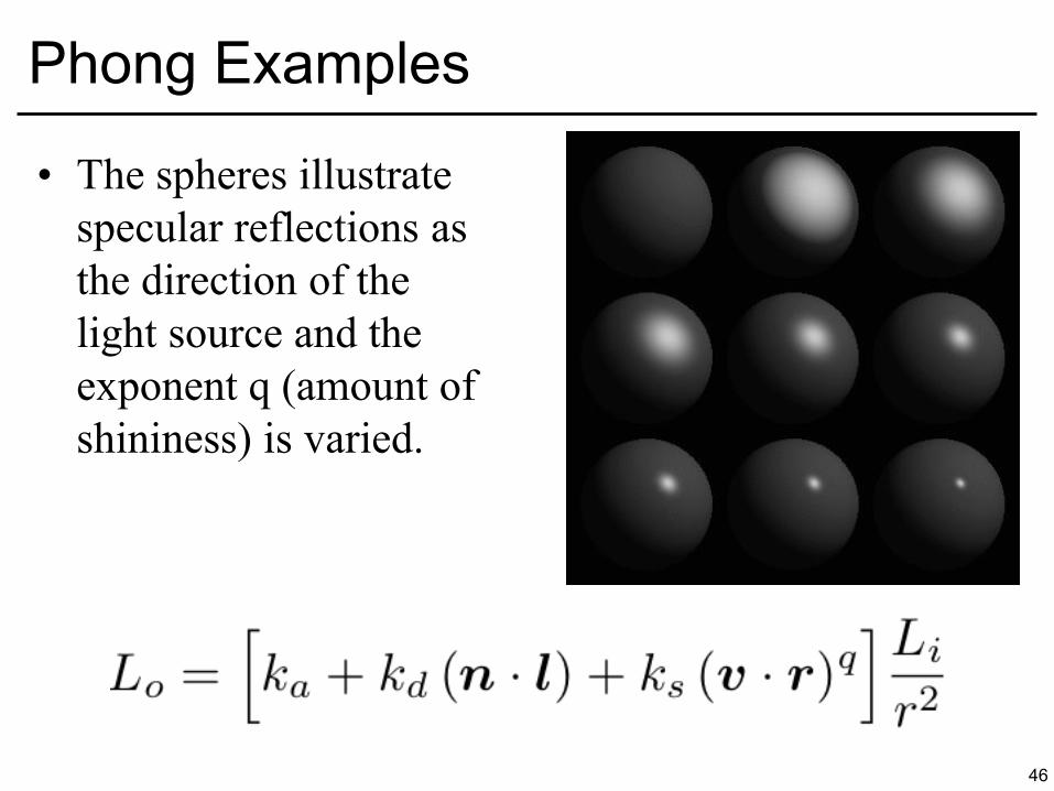
• The spheres illustrate specular reflections as the direction of the light source and the exponent q (amount of shininess) is varied.
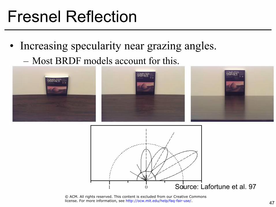
• Increasing specularity near grazing angles. – Most BRDF models account for this.
47
Fresnel Reflection
Source: Lafortune et al. 97 © ACM. All rights reserved. This content is excluded from our Creative Commonslicense. For more information, see http://ocw.mit.edu/help/faq-fair-use/.

48
Questions?
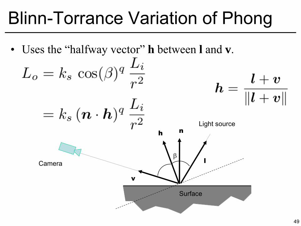
• Uses the “halfway vector” h between l and v.
49
Blinn-Torrance Variation of Phong
Surface
l
n
Camera
v
h
Light source

50
Lobe Comparison
Half vector lobe Mirror lobe
• Half vector lobe – Gradually narrower when approaching grazing
• Mirror lobe – Always circular
51
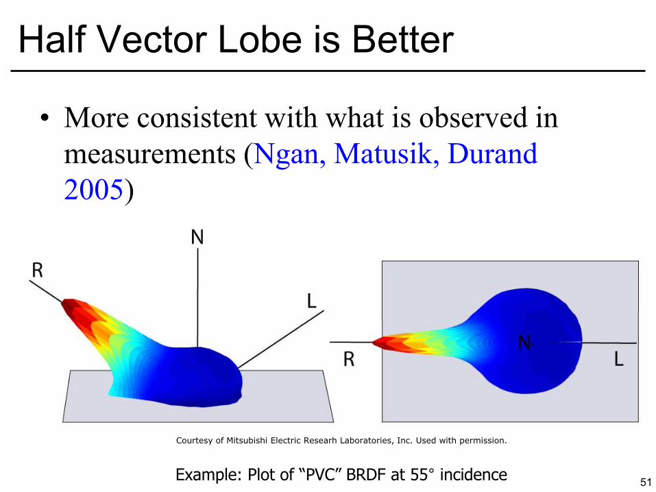
Half Vector Lobe is Better
• More consistent with what is observed in measurements (Ngan, Matusik, Durand 2005)
Example: Plot of “PVC” BRDF at 55° incidence
Courtesy of Mitsubishi Electric Researh Laboratories, Inc. Used with permission.

52
Questions?
• Example – Think of water surface as lots of tiny mirrors (microfacets) – “Bright” pixels are
• Microfacets aligned with the vector between sun and eye • But not the ones in shadow • And not the ones that are occluded
53
Microfacet Theory
Image of sunset removed due to copyright restrictions.
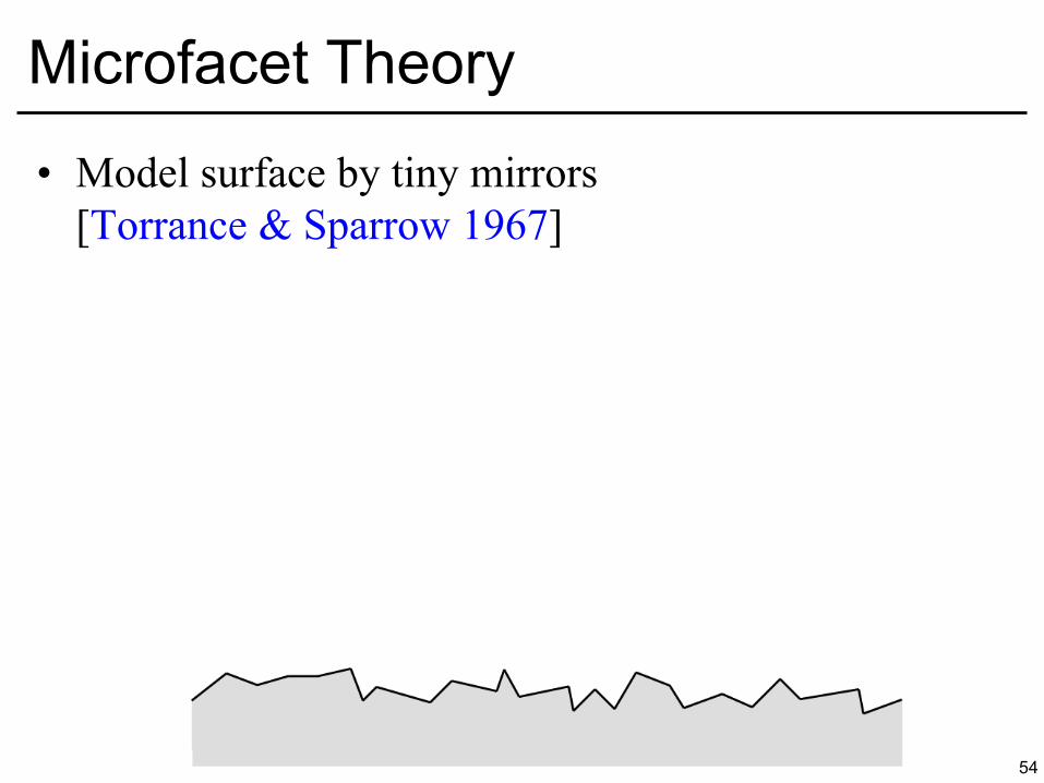
• Model surface by tiny mirrors [Torrance & Sparrow 1967]
54
Microfacet Theory
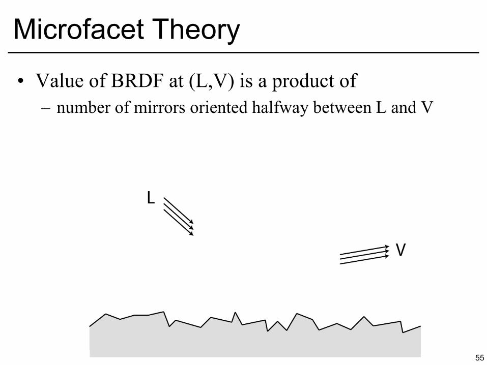
• Value of BRDF at (L,V) is a product of – number of mirrors oriented halfway between L and V
55
Microfacet Theory

• Value of BRDF at (L,V) is a product of – number of mirrors oriented halfway between L and V
56
Microfacet Theory

• Value of BRDF at (L,V) is a product of – number of mirrors oriented halfway between L and V
57
Microfacet Theory
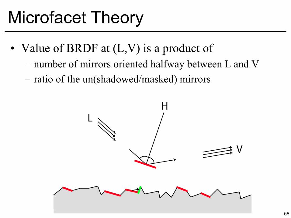
• Value of BRDF at (L,V) is a product of – number of mirrors oriented halfway between L and V – ratio of the un(shadowed/masked) mirrors
58
Microfacet Theory
59
Microfacet Theory
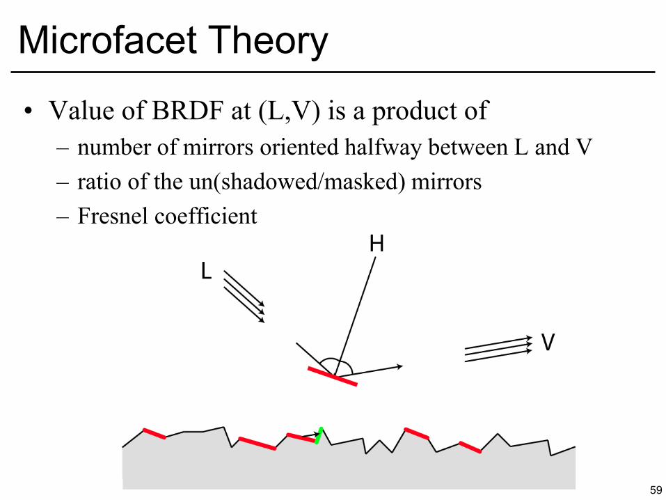
• Value of BRDF at (L,V) is a product of – number of mirrors oriented halfway between L and V – ratio of the un(shadowed/masked) mirrors – Fresnel coefficient
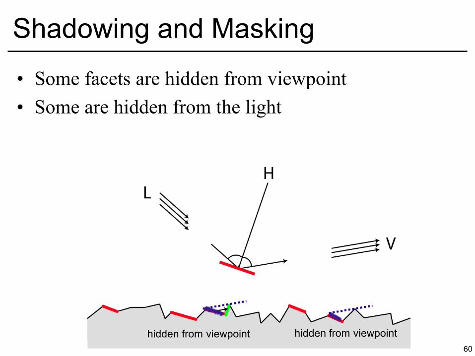
• Some facets are hidden from viewpoint • Some are hidden from the light
60
Shadowing and Masking
hidden from viewpoint hidden from viewpoint
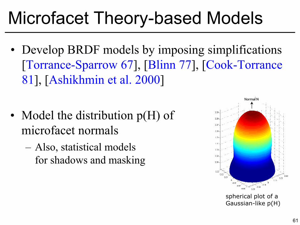
• Develop BRDF models by imposing simplifications [Torrance-Sparrow 67], [Blinn 77], [Cook-Torrance 81], [Ashikhmin et al. 2000]
• Model the distribution p(H) of microfacet normals – Also, statistical models
for shadows and masking
61
Microfacet Theory-based Models
spherical plot of a Gaussian-like p(H)
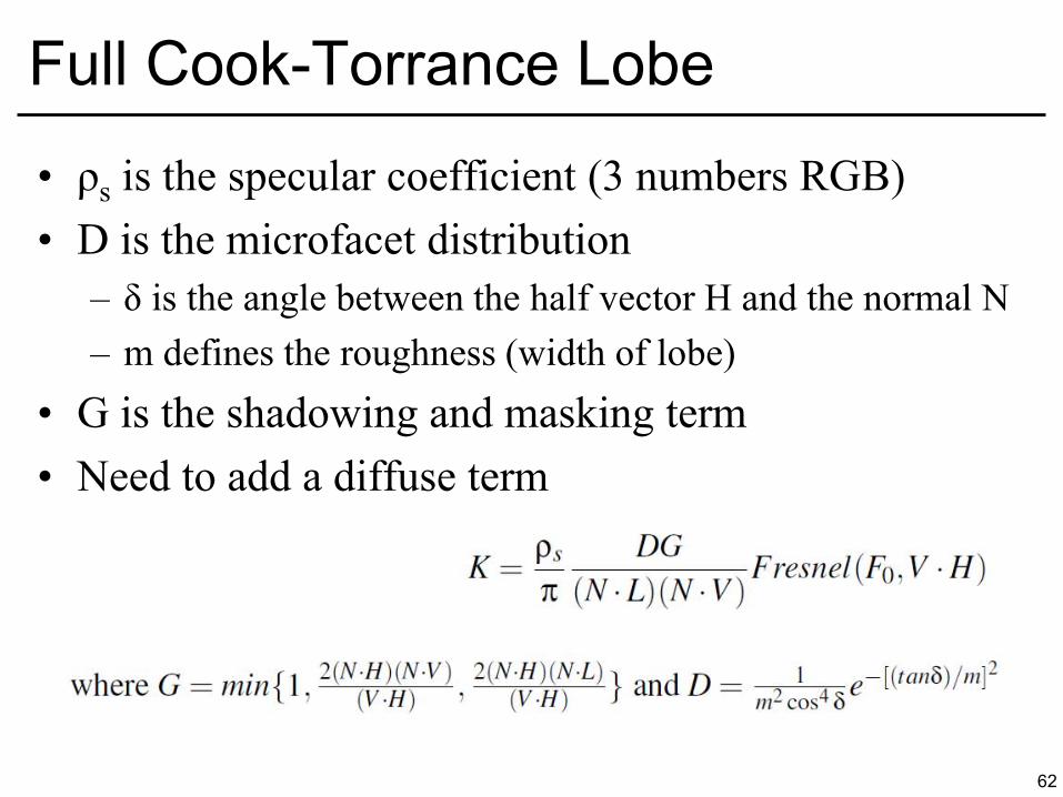
• ρs is the specular coefficient (3 numbers RGB) • D is the microfacet distribution
– δ is the angle between the half vector H and the normal N – m defines the roughness (width of lobe)
• G is the shadowing and masking term • Need to add a diffuse term
62
Full Cook-Torrance Lobe
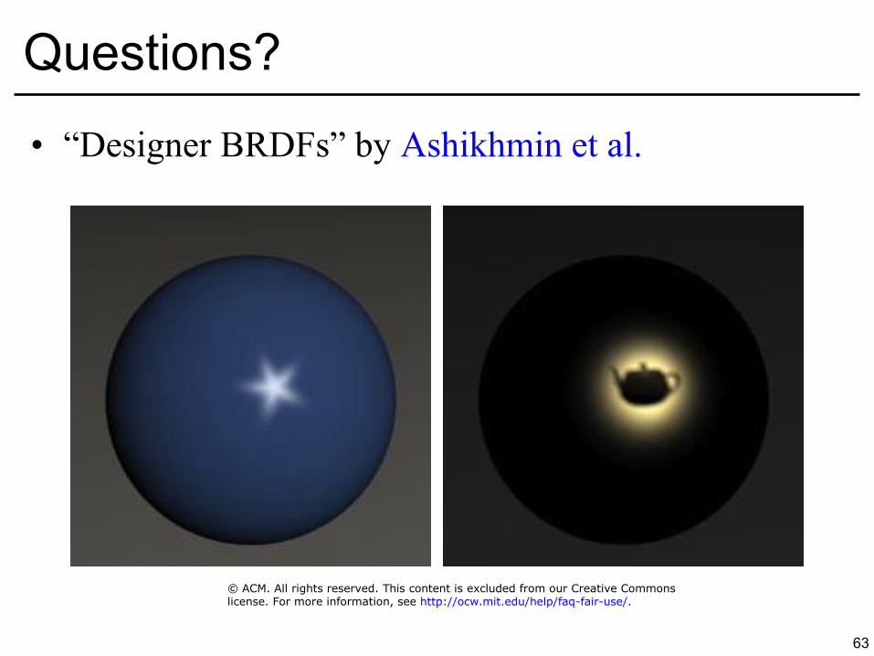
• “Designer BRDFs” by Ashikhmin et al.
63
Questions?
© ACM. All rights reserved. This content is excluded from our Creative Commonslicense. For more information, see http://ocw.mit.edu/help/faq-fair-use/.
64
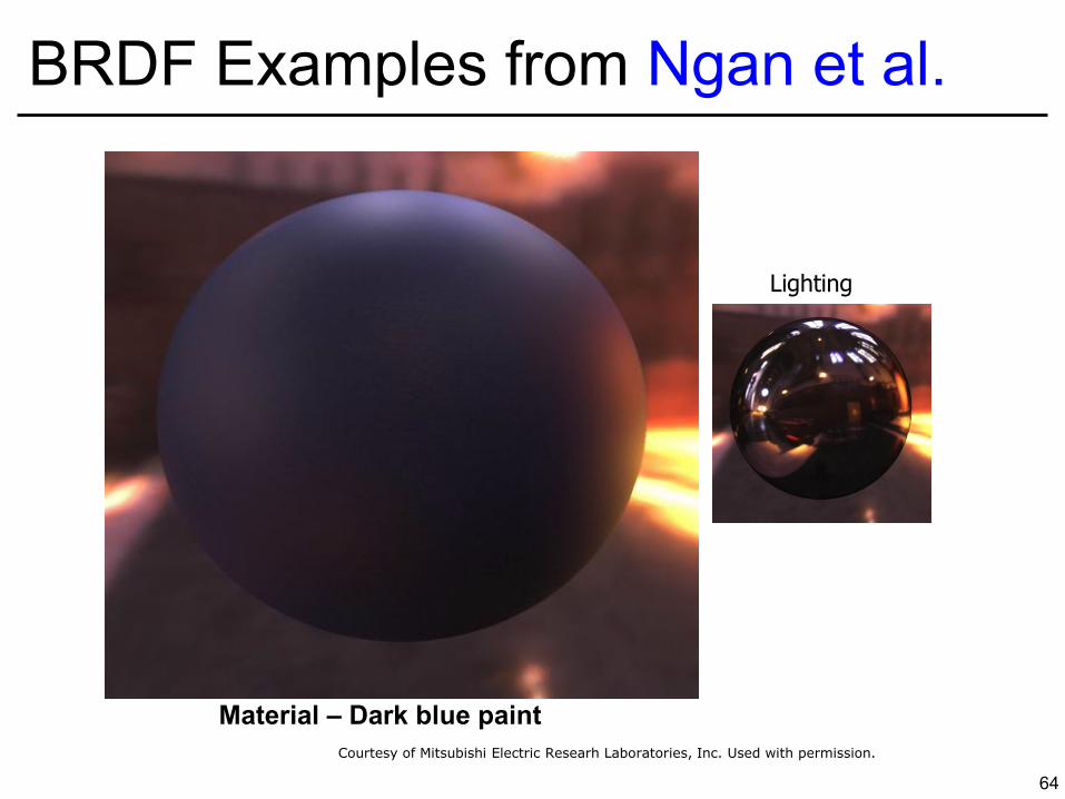
BRDF Examples from Ngan et al. Acquired data
Material – Dark blue paint
Lighting
Courtesy of Mitsubishi Electric Researh Laboratories, Inc. Used with permission.
65
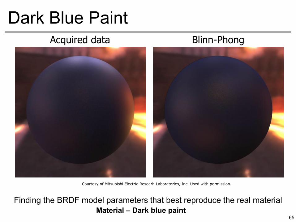
Dark Blue Paint Blinn-Phong
Material – Dark blue paint
Acquired data
Finding the BRDF model parameters that best reproduce the real material
Courtesy of Mitsubishi Electric Researh Laboratories, Inc. Used with permission.
66
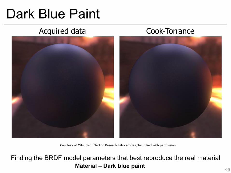
Dark Blue Paint Acquired data Cook-Torrance
Material – Dark blue paint
Finding the BRDF model parameters that best reproduce the real material
Courtesy of Mitsubishi Electric Researh Laboratories, Inc. Used with permission.
67
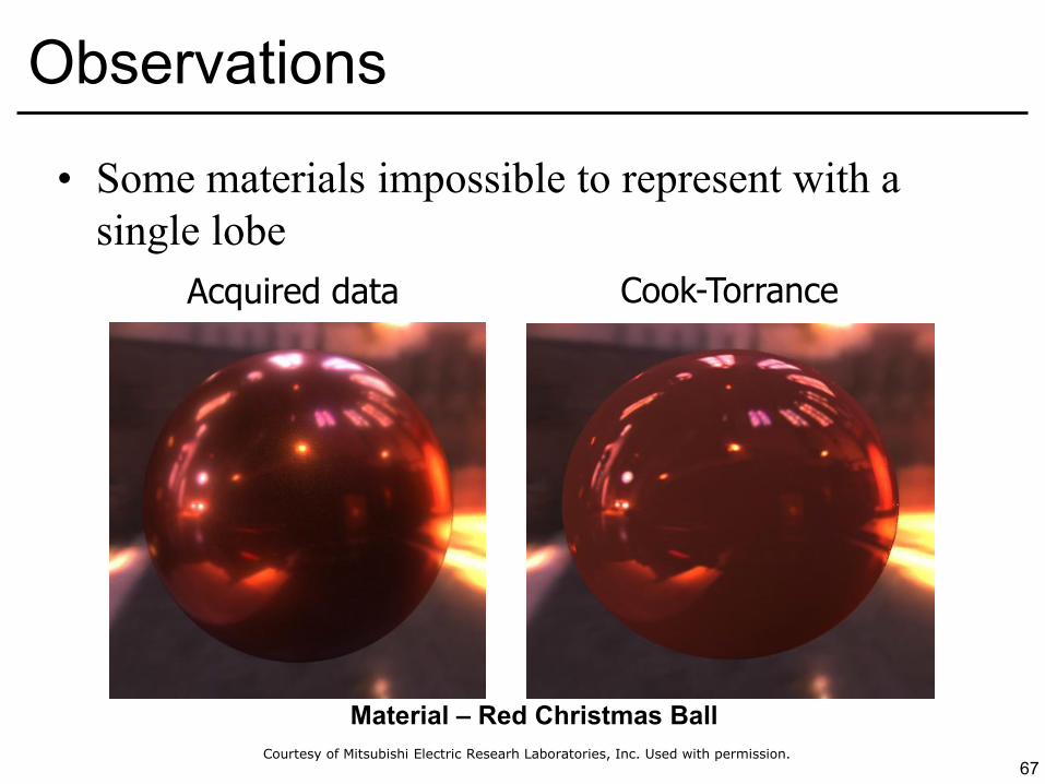
Observations
Material – Red Christmas Ball
Acquired data Cook-Torrance
• Some materials impossible to represent with a single lobe
Courtesy of Mitsubishi Electric Researh Laboratories, Inc. Used with permission.
68
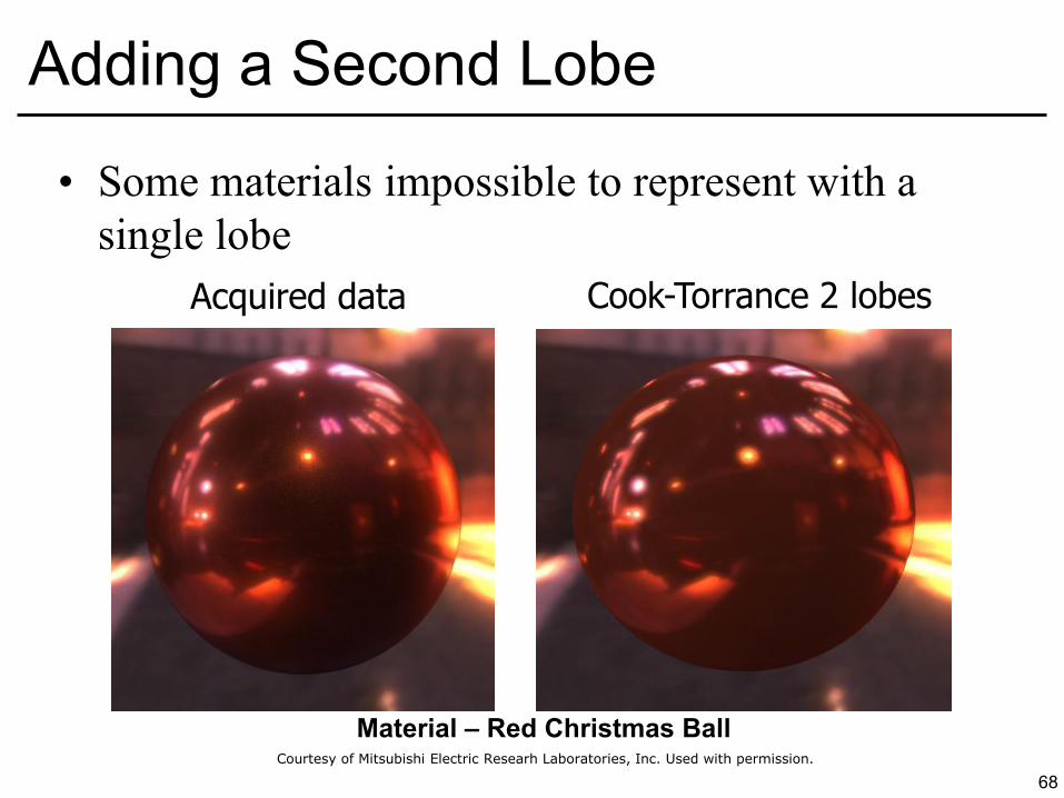
Adding a Second Lobe
Material – Red Christmas Ball
• Some materials impossible to represent with a single lobe
Cook-Torrance 2 lobes Acquired data
Courtesy of Mitsubishi Electric Researh Laboratories, Inc. Used with permission.
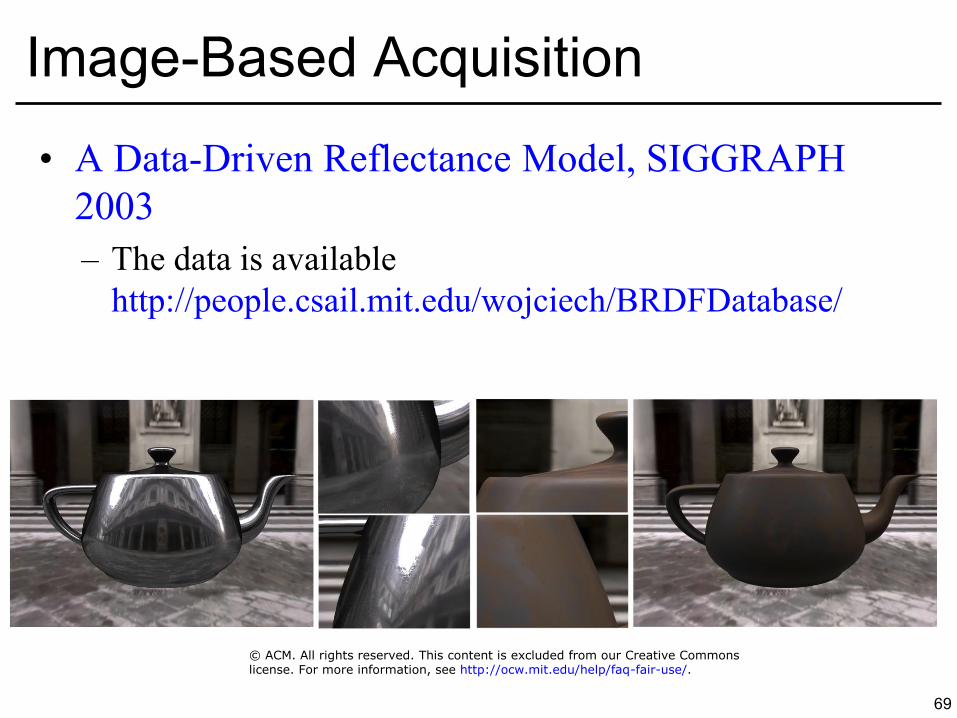
• A Data-Driven Reflectance Model, SIGGRAPH 2003 – The data is available
http://people.csail.mit.edu/wojciech/BRDFDatabase/
69
Image-Based Acquisition
© ACM. All rights reserved. This content is excluded from our Creative Commonslicense. For more information, see http://ocw.mit.edu/help/faq-fair-use/.
70
Questions? T. Weyrich et al., Fabricating
Microgeometry for Custom Surface Reflectance, SIGGRAPH 2009
Images of Fig. 1 and Fig. 6 in Weyrich T. et al, "Fabricating Microgeometry for Custom Surface Reflectance."SIGGRAPH '09 ACM SIGGRAPH 2009 papers; Article No. 32 --removed due to copyright restrictions.
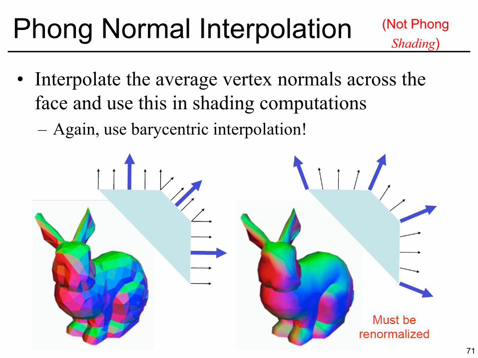
• Interpolate the average vertex normals across the face and use this in shading computations – Again, use barycentric interpolation!
71
Phong Normal Interpolation (Not Phong Shading)

72
That’s All for Today!
Images from the movie, “The Matrix,” removed due to copyright restrictions.
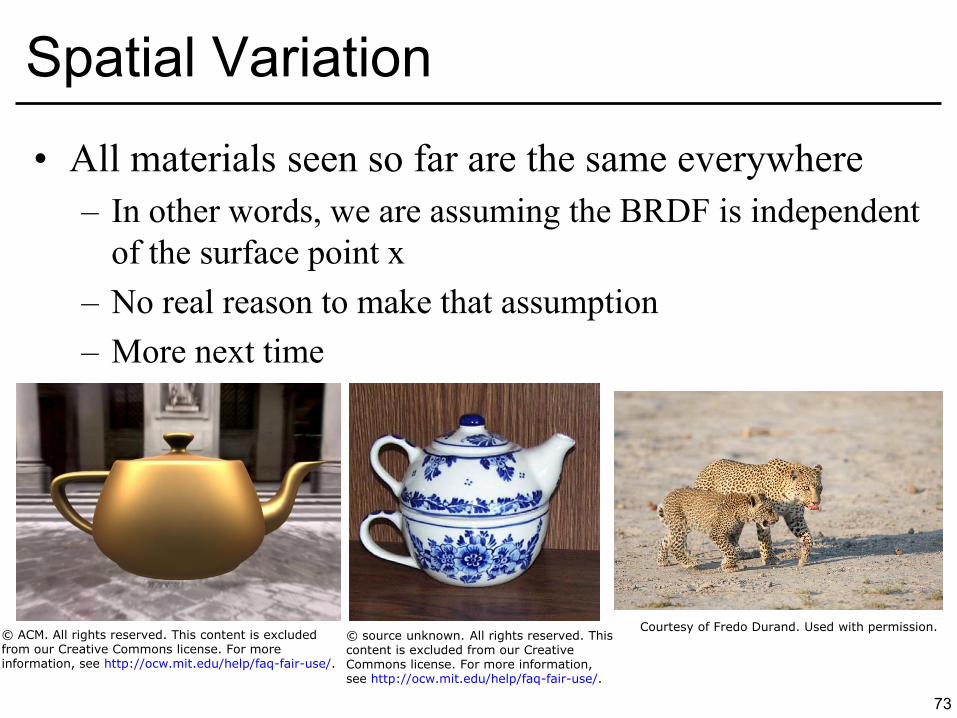
• All materials seen so far are the same everywhere – In other words, we are assuming the BRDF is independent
of the surface point x – No real reason to make that assumption – More next time
73
Spatial Variation
© ACM. All rights reserved. This content is excludedfrom our Creative Commons license. For moreinformation, see http://ocw.mit.edu/help/faq-fair-use/.
Courtesy of Fredo Durand. Used with permission.© source unknown. All rights reserved. Thiscontent is excluded from our CreativeCommons license. For more information,see http://ocw.mit.edu/help/faq-fair-use/.

MIT OpenCourseWarehttp://ocw.mit.edu
6.837 Computer GraphicsFall 2012
For information about citing these materials or our Terms of Use, visit: http://ocw.mit.edu/terms.