Embed Size (px)
Citation preview
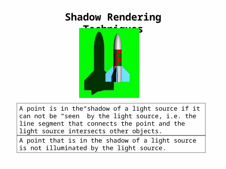
Shadow Rendering Techniques
A point is in the shadow of a light source if it can not be “seen” by the light source, i.e. the line segment that connects the point and the light source intersects other objects.
A point that is in the shadow of a light source is not illuminated by the light source.
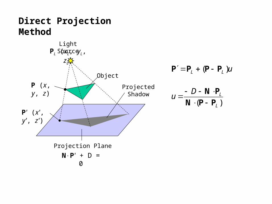
Direct Projection Method
Projection Plane
Light Source
Object
Projected Shadow
P (x, y, z)
P' (x', y', z')
PL (xL, yL, zL)
NP' + D = 0
uLL )( PPPP
)( L
LDu
PPN
PN
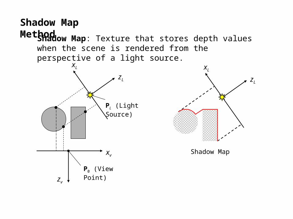
Shadow Map Method
xL
zL
Shadow Map
Shadow Map: Texture that stores depth values when the scene is rendered from the perspective of a light source.
xv
zv
zL
P0 (View Point)
PL (Light Source)
xL
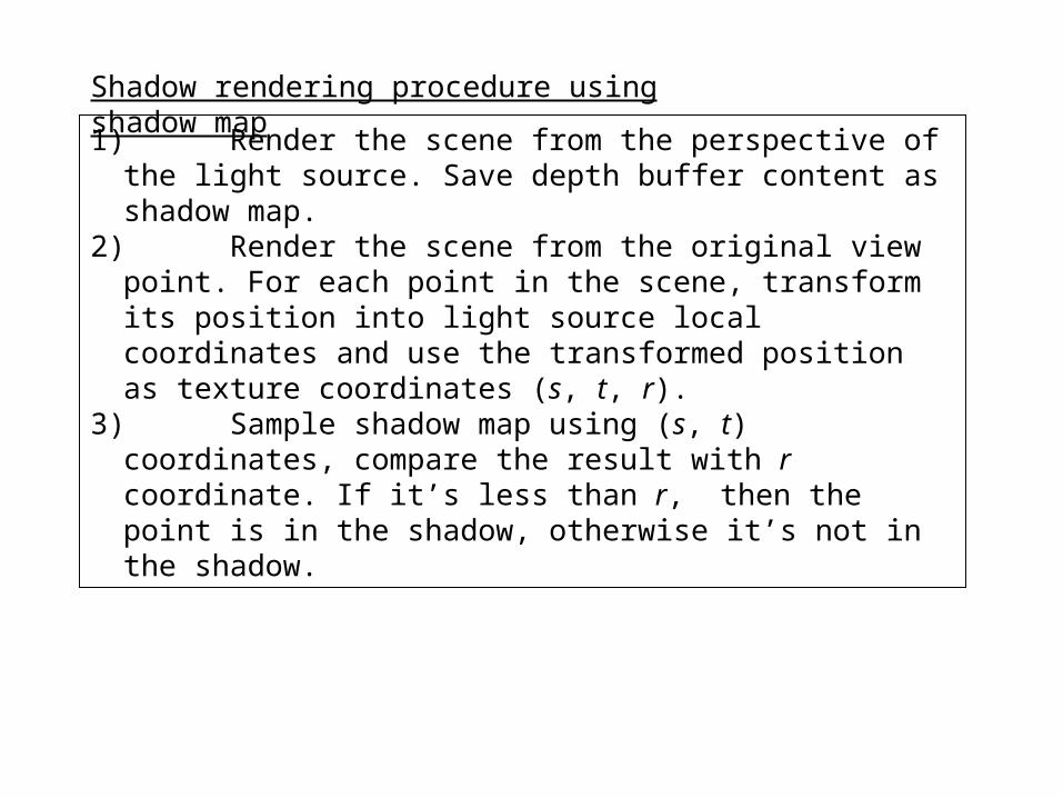
1) Render the scene from the perspective of the light source. Save depth buffer content as shadow map.
2) Render the scene from the original view point. For each point in the scene, transform its position into light source local coordinates and use the transformed position as texture coordinates (s, t, r).
3) Sample shadow map using (s, t) coordinates, compare the result with r coordinate. If it’s less than r, then the point is in the shadow, otherwise it’s not in the shadow.
Shadow rendering procedure using shadow map

Shadow Volume Method
Light Source
Object to cast shadow
Shadow Volume
Object Outline
Shadow Volume: An enclosed region of space that is formed by extruding object outline from the light source.

Z-Pass Shadow Volume Algorithm
Light Source
1. For each point in the scene, connect a line segment from this point to the view point;
2. Count the number of front facing and back facing shadow volume faces this line segment intersects: nf and nb;
3. If nf = nb the point is illuminated, otherwise it is in the shadow.
View Point
Illuminated
Illuminated
Shadowed
Shadow Volume
Object Outline
Z-Path algorithm generates incorrect results when the view point itself is in the shadow.
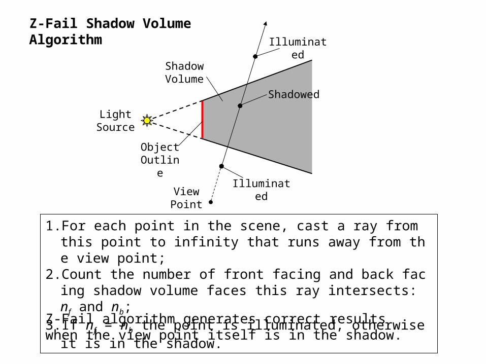
Z-Fail Shadow Volume Algorithm
Light Source
1. For each point in the scene, cast a ray from this point to infinity that runs away from the view point;
2. Count the number of front facing and back facing shadow volume faces this ray intersects: nf and nb;
3. If nf = nb the point is illuminated, otherwise it is in the shadow.
View Point
Illuminated
Illuminated
Shadowed
Shadow Volume
Object Outline
Z-Fail algorithm generates correct results when the view point itself is in the shadow.
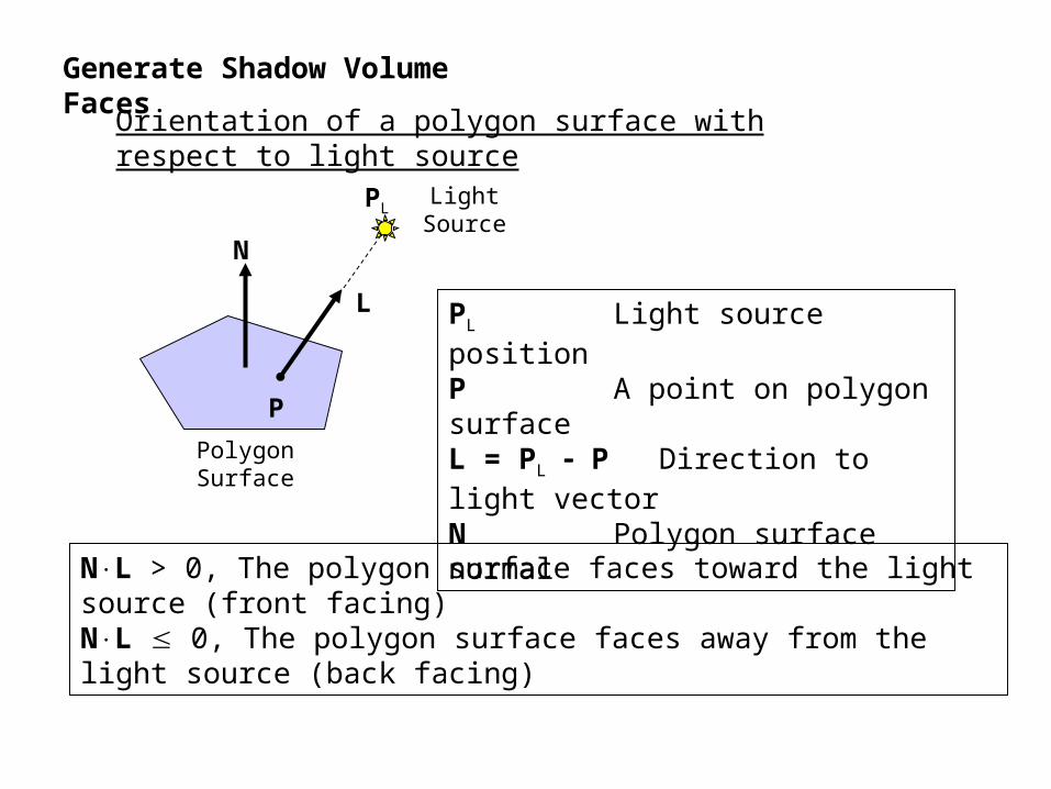
Generate Shadow Volume Faces
Orientation of a polygon surface with respect to light source
P
PL
N
L
Polygon Surface
Light Source
PL Light source positionP A point on polygon surfaceL = PL P Direction to light vectorN Polygon surface normal
NL > 0, The polygon surface faces toward the light source (front facing)NL 0, The polygon surface faces away from the light source (back facing)

Determine object outlines with respect to light source
Polygon Surfaces
Light Source
Polygon Edge
For each polygon edge:1. Find the two polygon surfaces that share this edge.2. Determine the orientations of these two surfaces with respect
to the light source.3. If one is facing toward the light and the other is facing away
from the light, then this polygon edge is an outline.
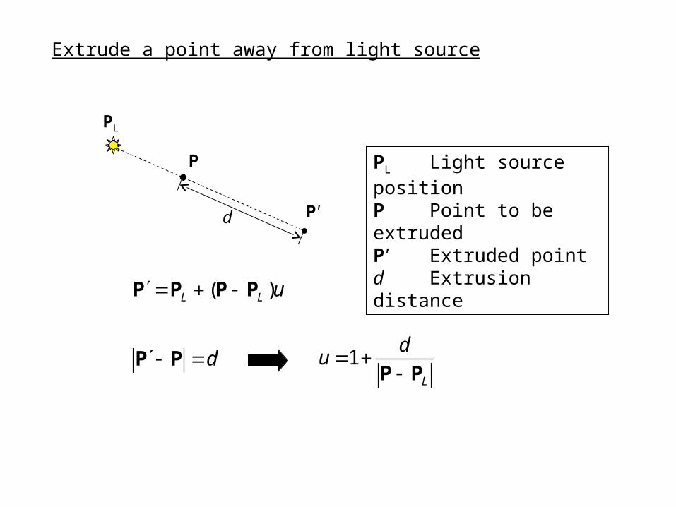
Extrude a point away from light source
P
P'
PL
uLL )( PPPP
d
PL Light source positionP Point to be extrudedP' Extruded pointd Extrusion distance
d PPL
du
PP 1
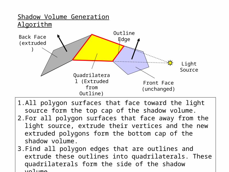
Shadow Volume Generation Algorithm
Front Face (unchanged)
Light Source
Outline Edge
1. All polygon surfaces that face toward the light source form the top cap of the shadow volume.
2. For all polygon surfaces that face away from the light source, extrude their vertices and the new extruded polygons form the bottom cap of the shadow volume.
3. Find all polygon edges that are outlines and extrude these outlines into quadrilaterals. These quadrilaterals form the side of the shadow volume.
Back Face (extruded)
Quadrilateral (Extruded from
Outline)

Shadow Volume Using Stencil Buffer
1. Render the scene with all light sources turned off.2. Clear Stencil Buffer3. Turn off depth buffer and color buffer writes.4. Render all shadow volume faces facing away from the viewer. Increase s
tencil buffer value by one for each point that fails the depth test. 5. Render all shadow volume faces facing towards the viewer. Decease sten
cil buffer value by one for each point that fails the depth test. 6. Turn on depth buffer and color buffer writes.7. Render the scene again with light source turned on and only where the st
encil buffer value is zero. 8. Repeat 2, 3, 4, 5, 6, 7 for each light source.
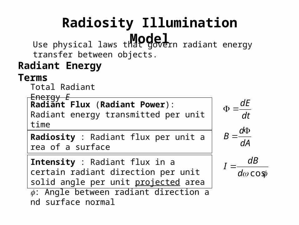
Radiosity Illumination Model
Use physical laws that govern radiant energy transfer between objects.
Radiant Energy Terms
Total Radiant Energy E
Radiant Flux (Radiant Power): Radiant energy transmitted per unit time dt
dE
Radiosity : Radiant flux per unit area of a surfacedA
dB
Intensity : Radiant flux in a certain radiant direction per unit solid angle per unit projected area cosd
dBI
: Angle between radiant direction and surface normal
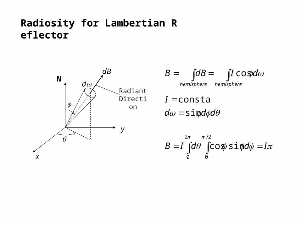
Radiosity for Lambertian Reflector
x
y
N
d
dB
Radiant Direction
hemispherehemisphere
dIdBB cos
ddd sin
IddIB 2/
0
2
0
sincos
constantI

Form Factor
Form Factor Fjk: Fractional amount of radiant energy from surface j that reaches surface k.
Surface j
Surface kNj
ddBj
Nk
dAj
dAk
j
k
r
2
cos
r
dAd kk

2,
coscoscos
r
dA
I
dI
B
dB
dAB
dAdBF kkj
j
jj
j
j
jj
jjdAdA kj
j kA A
jkkj
jjk dAdA
rAF
2
coscos1
Properties of form factors
kjkjkj FAFA
0jjFFor planar surface and convex surface
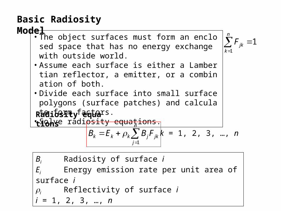
Basic Radiosity Model
• The object surfaces must form an enclosed space that has no energy exchange with outside world.
• Assume each surface is either a Lambertian reflector, a emitter, or a combination of both.
• Divide each surface into small surface polygons (surface patches) and calculate form factors.
• Solve radiosity equations.
Bi Radiosity of surface iEi Energy emission rate per unit area of surface ii Reflectivity of surface ii = 1, 2, 3, …, n
Radiosity equations
n
jjkjkkk FBEB
1
k = 1, 2, 3, …, n
11
n
kjkF
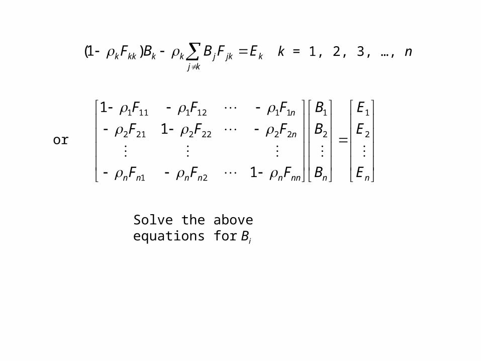
k = 1, 2, 3, …, nkkj
jkjkkkkk EFBBF
)1(
nnnnnnnnn
n
n
E
E
E
B
B
B
FFF
FFF
FFF
2
1
2
1
21
22222212
11121111
1
1
1
or
Solve the above equations for Bi
Ray-Tracing Methods
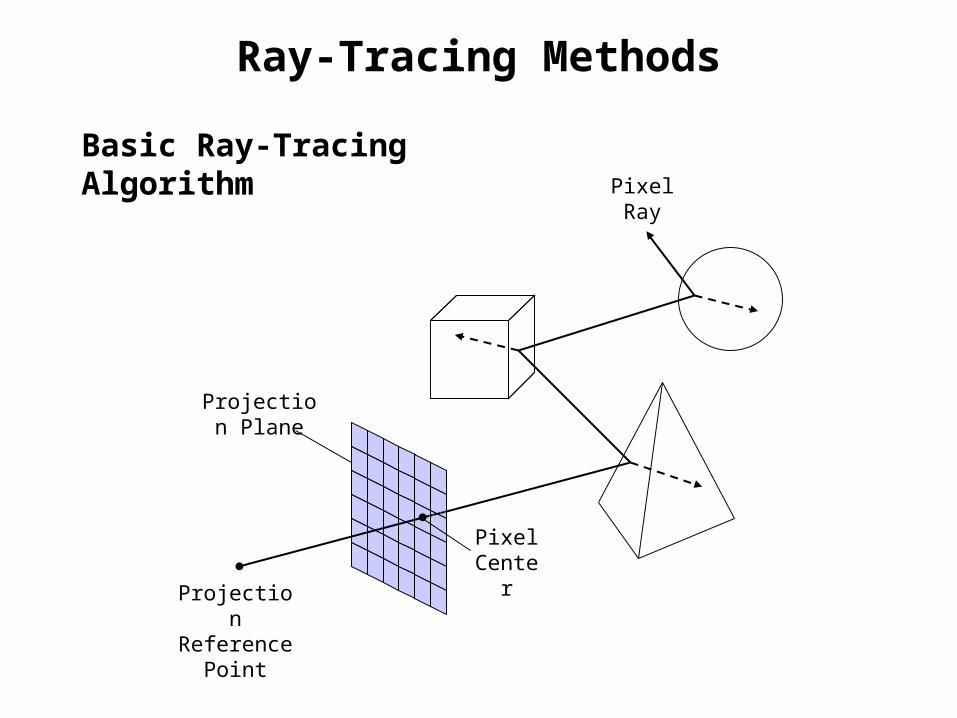
Basic Ray-Tracing Algorithm
Projection Reference
Point
Pixel Center
Pixel Ray
Projection Plane

1. Cast pixel ray from projection reference point through pixel center.2. Each time a pixel ray intersects an object surface, it splits into two
secondary rays: a reflection ray and a refraction ray. (No refraction ray for opaque object.)
3. Repeat step 2 for each pixel ray. Each intersected surface is added to a binary ray-tracing tree.
4. A pixel ray is terminated when the ray intersects no surfaces, intersects a light source that is not a reflecting surface, or the ray-tracing tree reaches maximum allowable depth.
Ray Casting Procedure
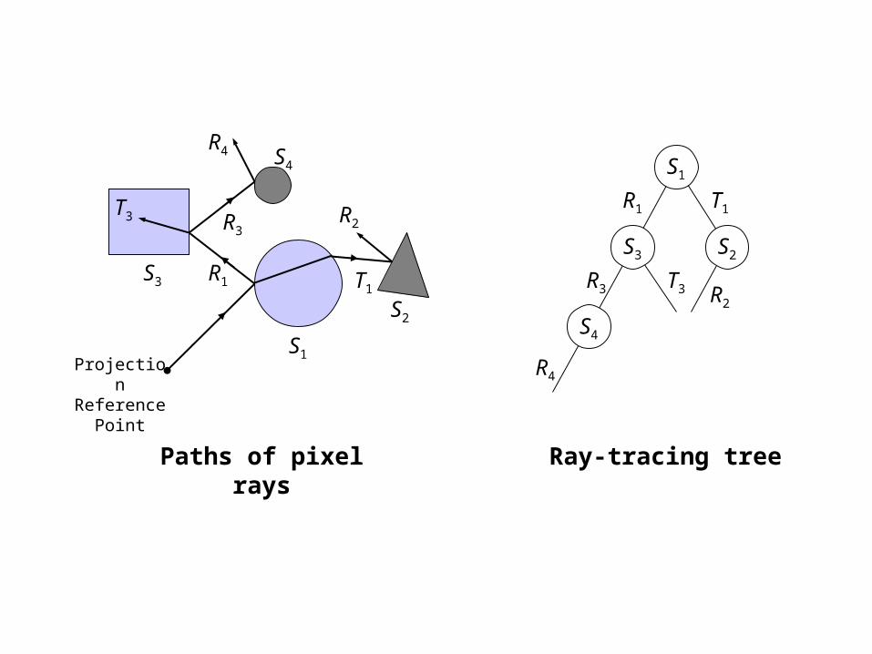
S1
S2
S3
S4
R1 T1
R2R3
T3
R4
Projection Reference
Point
S1
S2S3
S4
T1R1
R2
R3 T3
R4
Paths of pixel rays Ray-tracing tree

Pixel Intensity Calculation
The ray-tracing tree is processed in bottom-up order. (Trace each pixel ray backward.)
• For each pixel ray at the bottom of the tree, its intensity is assigned a background intensity value if it does not intersect a light source. Otherwise the intensity is assigned to the light source intensity.
• At each surface intersection, the intensities from reflection ray, refraction ray and intensity contributions from all the light sources are accumulated for the parent ray.
• Pixel ray intensity is attenuated by the distance it travels.• The pixel intensity is obtained at the root of the tree.
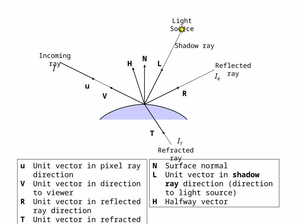
N
R
L
V
H
Light Source
Incoming ray
Reflected ray
Shadow ray
Refracted ray
T
u
u Unit vector in pixel ray directionV Unit vector in direction to viewerR Unit vector in reflected ray directionT Unit vector in refracted ray direction
N Surface normalL Unit vector in shadow ray direction
(direction to light source)H Halfway vector
IR
IT
I

TtRs
n
l
nlss
ldd
la
lriaae IkIkIkIkffIkII
l
1
)()( HNLN
VL
VLH
NuNuR )2( uNTr
iri
r
i
coscos
uV
kt: Transparency coefficient
otherwise,1
objectsother intersects sourcelight ray toshadow If,0 ii
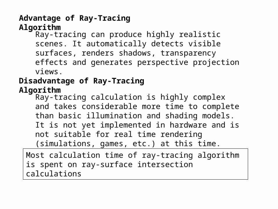
Advantage of Ray-Tracing Algorithm
Ray-tracing can produce highly realistic scenes. It automatically detects visible surfaces, renders shadows, transparency effects and generates perspective projection views.
Disadvantage of Ray-Tracing Algorithm
Ray-tracing calculation is highly complex and takes considerable more time to complete than basic illumination and shading models. It is not yet implemented in hardware and is not suitable for real time rendering (simulations, games, etc.) at this time.
Most calculation time of ray-tracing algorithm is spent on ray-surface intersection calculations
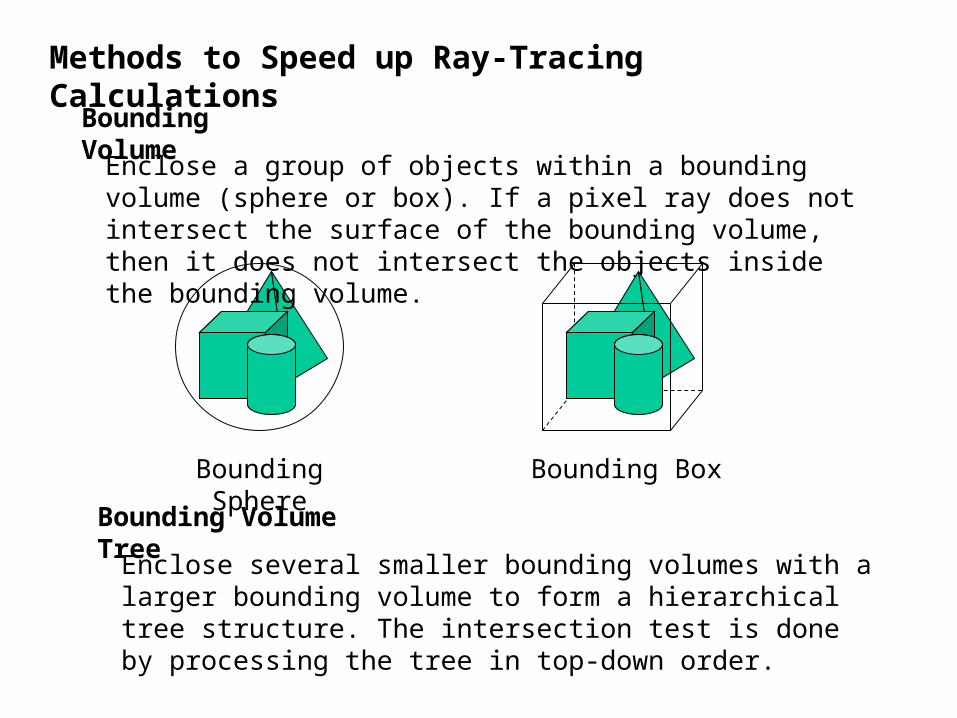
Methods to Speed up Ray-Tracing Calculations
Bounding Volume
Enclose a group of objects within a bounding volume (sphere or box). If a pixel ray does not intersect the surface of the bounding volume, then it does not intersect the objects inside the bounding volume.
Bounding Sphere Bounding Box
Bounding Volume Tree
Enclose several smaller bounding volumes with a larger bounding volume to form a hierarchical tree structure. The intersection test is done by processing the tree in top-down order.

Space Subdivision Methods
• Obtain bounding box for the entire scene• Divide the bounding box into a number of sub regions (cells).
Sub regions are usually rectangular solids.• Each cell is associated with a list of objects it contains.• For each pixel ray, trace the cells it intersects and only perform
intersection tests for objects within these cells.
Pixel ray
Pixel ray
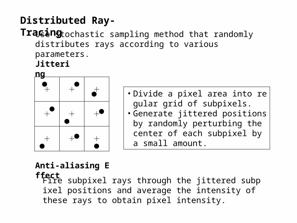
Distributed Ray-TracingUse stochastic sampling method that randomly distributes rays according to various parameters.
Jittering
• Divide a pixel area into regular grid of subpixels.
• Generate jittered positions by randomly perturbing the center of each subpixel by a small amount.
Anti-aliasing Effect
Fire subpixel rays through the jittered subpixel positions and average the intensity of these rays to obtain pixel intensity.
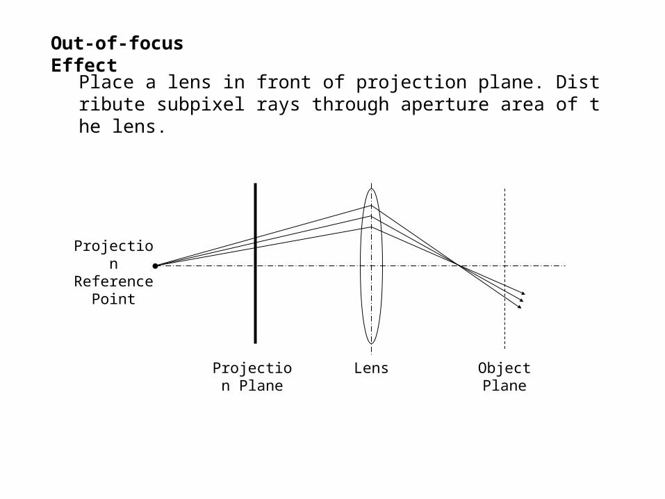
Out-of-focus Effect
Place a lens in front of projection plane. Distribute subpixel rays through aperture area of the lens.
Projection Reference
Point
Projection Plane
Object Plane
Lens
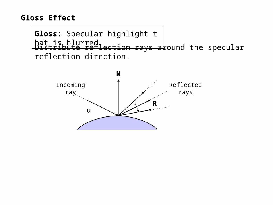
Gloss Effect
Gloss: Specular highlight that is blurred.
Distribute reflection rays around the specular reflection direction.
N
R
Incoming ray Reflected rays
u

Translucency Effect
Translucency: Light passing through the material is scattered so that objects behind the material appear blurred.
Distribute refraction rays around the ideal refraction direction.
N
T
Incoming ray
Refracted rays
u
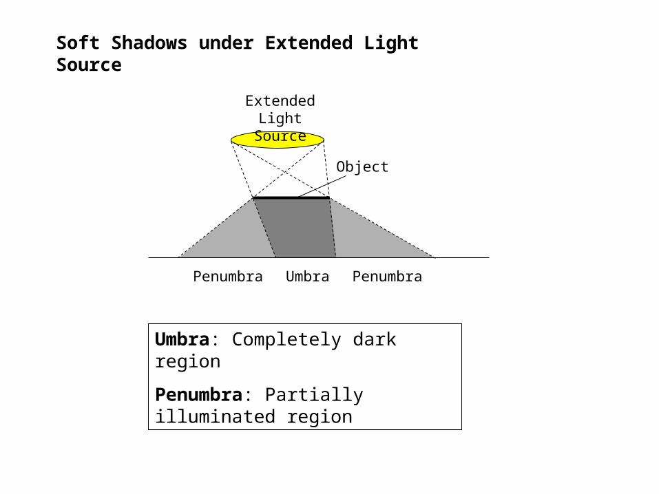
Soft Shadows under Extended Light Source
Extended Light Source
Object
UmbraPenumbra Penumbra
Umbra: Completely dark region
Penumbra: Partially illuminated region
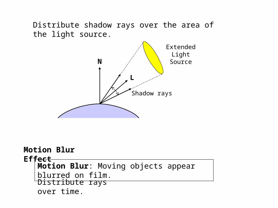
Motion Blur Effect
Distribute rays over time.
Motion Blur: Moving objects appear blurred on film.
Distribute shadow rays over the area of the light source.
N
L
Shadow rays
Extended Light Source


![[Adamek Chris] Light, Shadow](https://img.pdfslide.net/doc/110x75/577cda5e1a28ab9e78a57f36/adamek-chris-light-shadow.jpg)