Embed Size (px)
Citation preview
Shaping and Homogenization of LED
White Light Using Aperiodic Scattering
Cells Array
Huiying Zhong, Roberto Knoth, Christian Hellmann, Liangxin Yang,
Frank Wyrowski
SPIE 10379-12
Background / Motivation
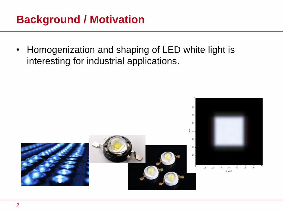
• Homogenization and shaping of LED white light is
interesting for industrial applications.
2

Background / Motivation
• Homogenization and shaping of LED white light is
interesting for industrial applications.
Task: Homogenization and shaping of LED white
light !
3
Background / Motivation
• Homogenization and shaping of LED white light is
interesting for industrial applications.
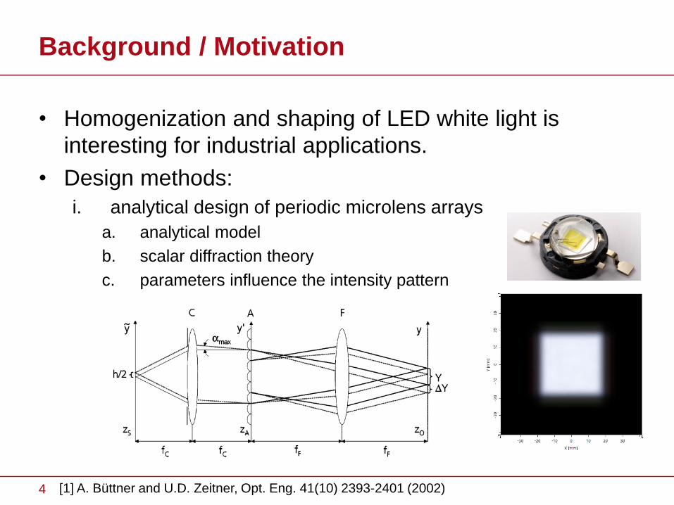
• Design methods:
i. analytical design of periodic microlens arrays
a. analytical model
b. scalar diffraction theory
c. parameters influence the intensity pattern
[1] A. Büttner and U.D. Zeitner, Opt. Eng. 41(10) 2393-2401 (2002)4
Background / Motivation
• Homogenization and shaping of LED white light is
interesting for industrial applications.
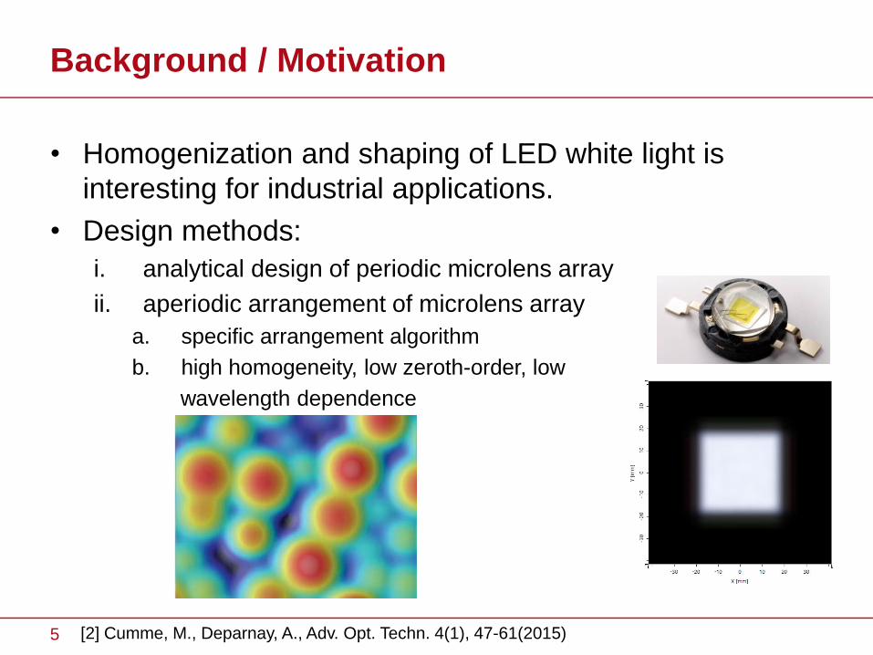
• Design methods:
i. analytical design of periodic microlens array
ii. aperiodic arrangement of microlens array
a. specific arrangement algorithm
b. high homogeneity, low zeroth-order, low
wavelength dependence
[2] Cumme, M., Deparnay, A., Adv. Opt. Techn. 4(1), 47-61(2015)5
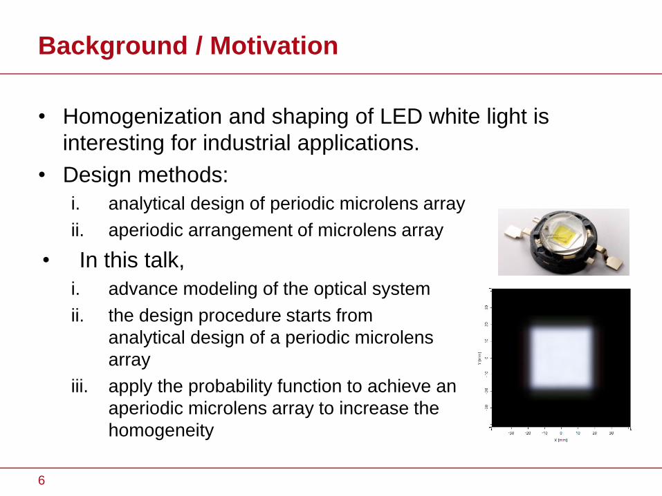
Background / Motivation
• Homogenization and shaping of LED white light is
interesting for industrial applications.
• Design methods:
i. analytical design of periodic microlens array
ii. aperiodic arrangement of microlens array
• In this talk,
i. advance modeling of the optical system
ii. the design procedure starts from
analytical design of a periodic microlens
array
iii. apply the probability function to achieve an
aperiodic microlens array to increase the
homogeneity
6
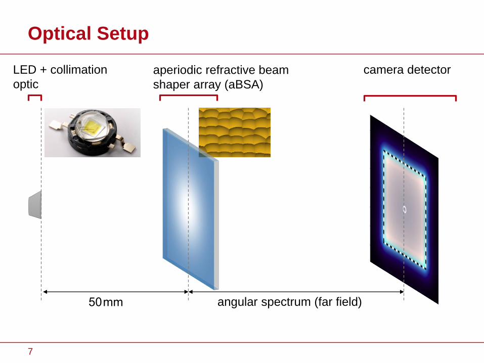
Optical Setup
50 mm angular spectrum (far field)
LED + collimation
optic
aperiodic refractive beam
shaper array (aBSA)
camera detector
7
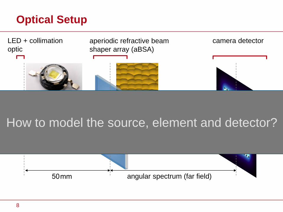
Optical Setup
50 mm angular spectrum (far field)
LED + collimation
optic
aperiodic refractive beam
shaper array (aBSA)
camera detector
How to model the source, element and detector?
8

Light Source: Lateral Modes
here
a set of point sources
9
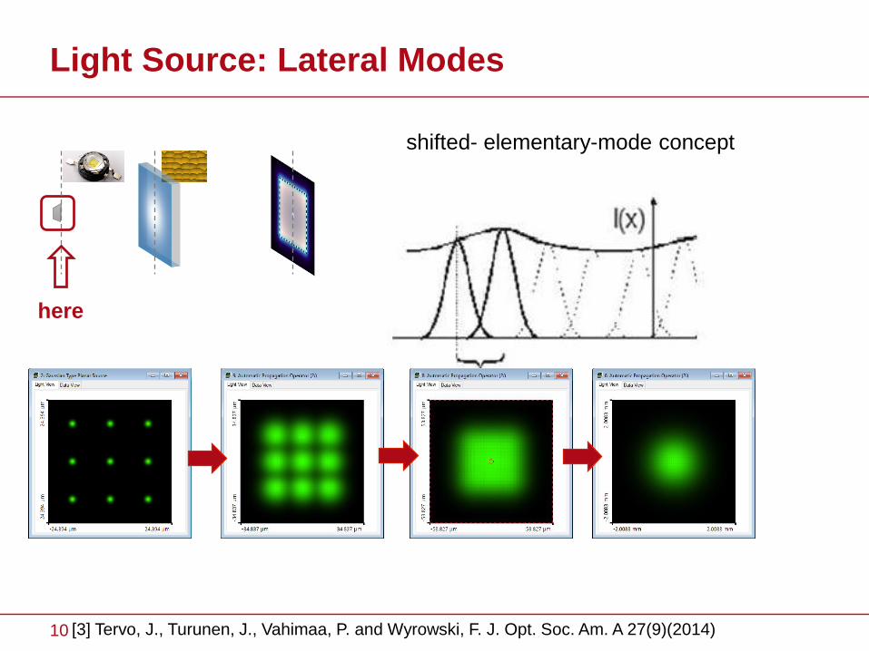
Light Source: Lateral Modes
here
shifted- elementary-mode concept
[3] Tervo, J., Turunen, J., Vahimaa, P. and Wyrowski, F. J. Opt. Soc. Am. A 27(9)(2014)10
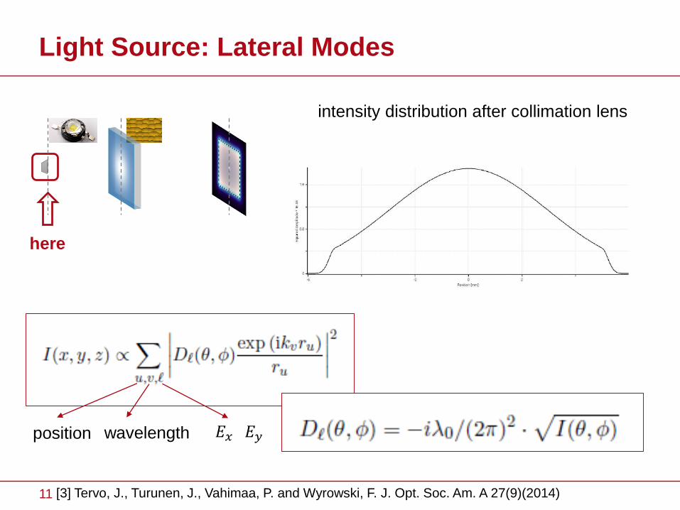
Light Source: Lateral Modes
here
intensity distribution after collimation lens
position wavelength 𝐸𝑥 𝐸𝑦
11 [3] Tervo, J., Turunen, J., Vahimaa, P. and Wyrowski, F. J. Opt. Soc. Am. A 27(9)(2014)
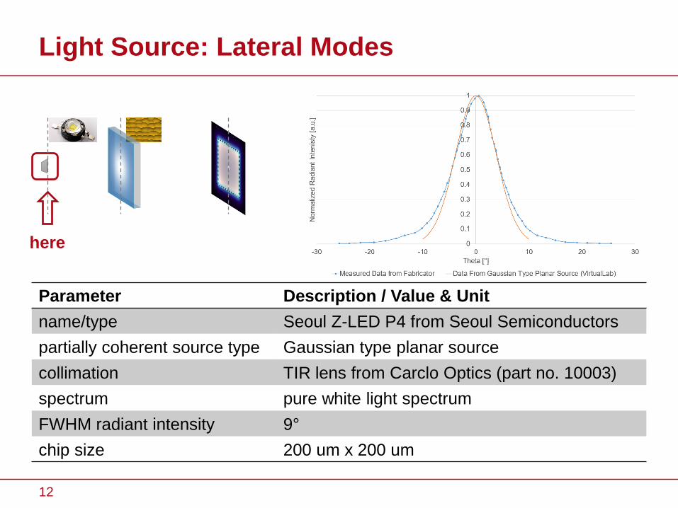
Parameter Description / Value & Unit
name/type Seoul Z-LED P4 from Seoul Semiconductors
partially coherent source type Gaussian type planar source
collimation TIR lens from Carclo Optics (part no. 10003)
spectrum pure white light spectrum
FWHM radiant intensity 9°
chip size 200 um x 200 um
Light Source: Lateral Modes
radiant intensity
here
12
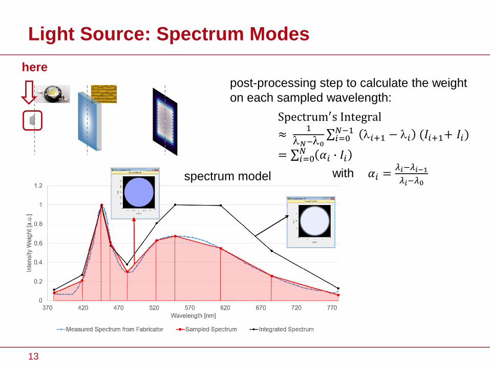
Light Source: Spectrum Modes
spectrum model
here
post-processing step to calculate the weight
on each sampled wavelength:
Spectrum′s Integral
≈1
𝑁−0σ𝑖=0𝑁−1 𝑖+1 − 𝑖 (𝐼𝑖+1+ 𝐼𝑖)
= σ𝑖=0𝑁 𝛼𝑖 ∙ 𝐼𝑖
with 𝛼𝑖 =𝜆𝑖−𝜆𝑖−1
𝜆𝑖−𝜆0
13
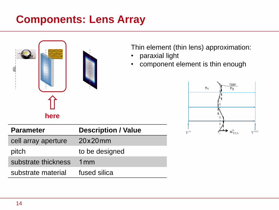
Components: Lens Array
Parameter Description / Value
cell array aperture 20 x 20 mm
pitch to be designed
substrate thickness 1 mm
substrate material fused silica
here
Thin element (thin lens) approximation:
• paraxial light
• component element is thin enough
14
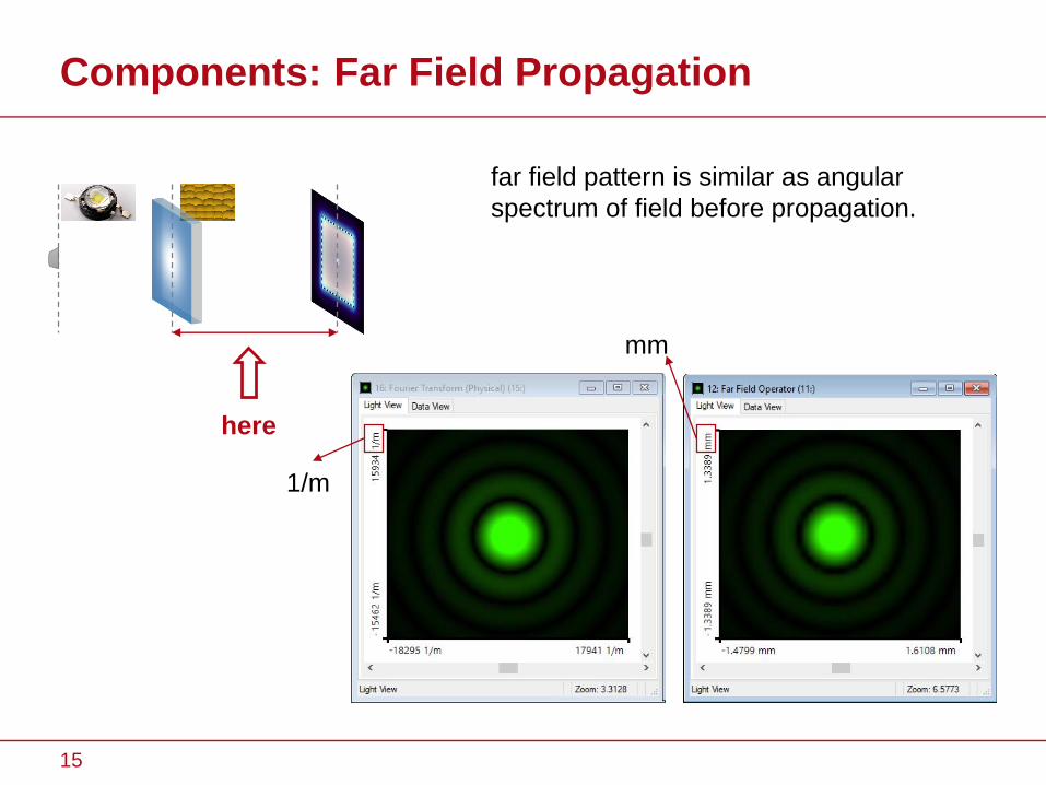
Components: Far Field Propagation
here
far field pattern is similar as angular
spectrum of field before propagation.
1/m
mm
15
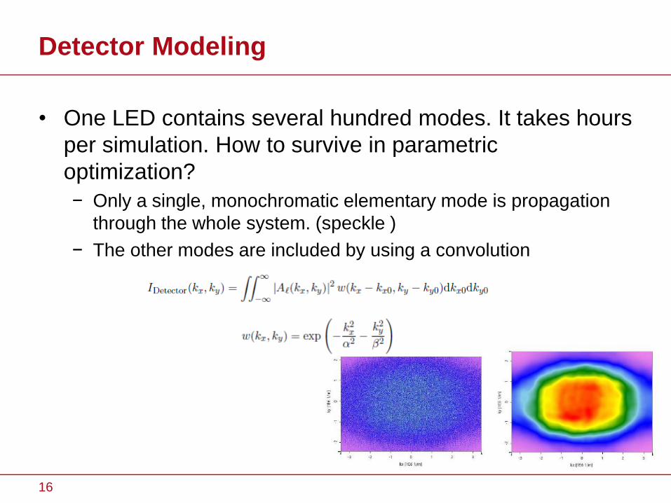
Detector Modeling
• One LED contains several hundred modes. It takes hours
per simulation. How to survive in parametric
optimization?
− Only a single, monochromatic elementary mode is propagation
through the whole system. (speckle )
− The other modes are included by using a convolution
16
Detector Modeling
• One LED contains several hundred modes. It takes hours
per simulation. How to survive in parametric
optimization?
− Only a single, monochromatic elementary mode is propagation
through the whole system. (speckle )
− The other modes are included by using a convolution
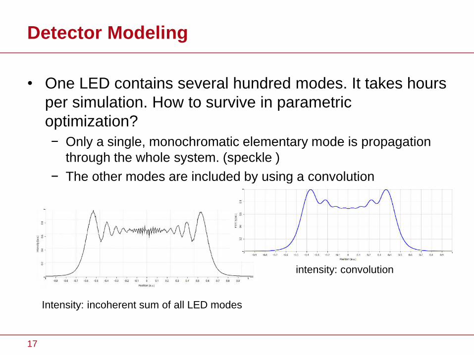
Intensity: incoherent sum of all LED modes
intensity: convolution
17
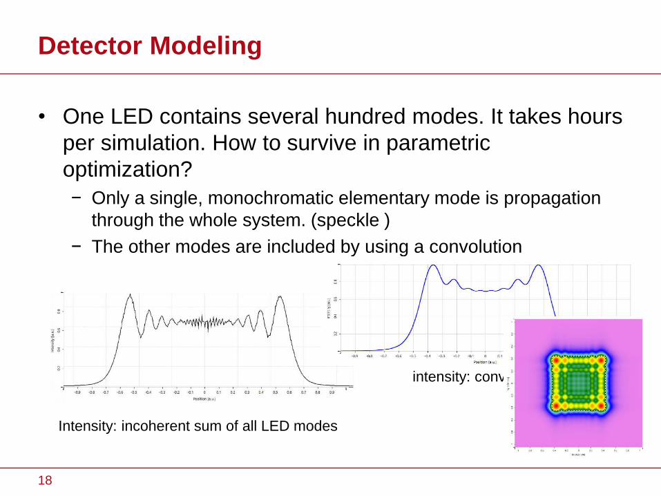
Detector Modeling
• One LED contains several hundred modes. It takes hours
per simulation. How to survive in parametric
optimization?
− Only a single, monochromatic elementary mode is propagation
through the whole system. (speckle )
− The other modes are included by using a convolution
Intensity: incoherent sum of all LED modes
intensity: convolution
18
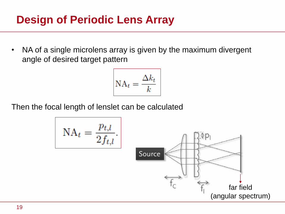
Design of Periodic Lens Array
• NA of a single microlens array is given by the maximum divergent
angle of desired target pattern
Then the focal length of lenslet can be calculated
19
far field
(angular spectrum)
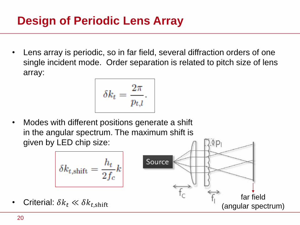
• Lens array is periodic, so in far field, several diffraction orders of one
single incident mode. Order separation is related to pitch size of lens
array:
• Modes with different positions generate a shift
in the angular spectrum. The maximum shift is
given by LED chip size:
• Criterial: 𝛿𝑘𝑡 ≪ 𝛿𝑘𝑡,shift
Design of Periodic Lens Array
far field
(angular spectrum)
20
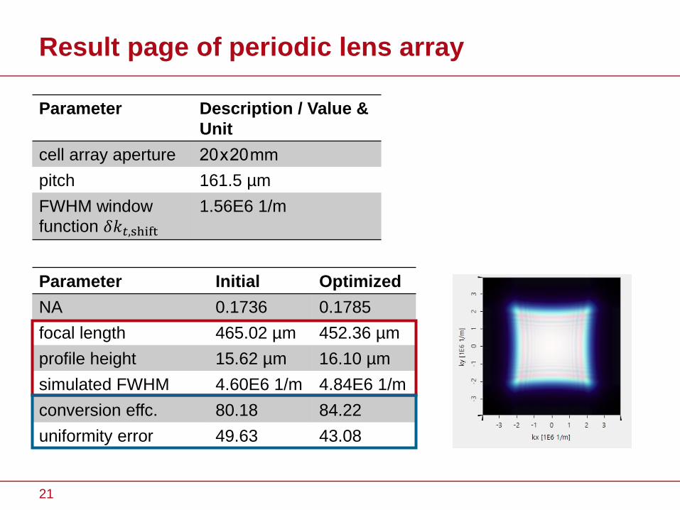
Result page of periodic lens array
21
Parameter Description / Value &
Unit
cell array aperture 20 x 20 mm
pitch 161.5 µm
FWHM window
function 𝛿𝑘𝑡,shift
1.56E6 1/m
Parameter Initial Optimized
NA 0.1736 0.1785
focal length 465.02 µm 452.36 µm
profile height 15.62 µm 16.10 µm
simulated FWHM 4.60E6 1/m 4.84E6 1/m
conversion effc. 80.18 84.22
uniformity error 49.63 43.08
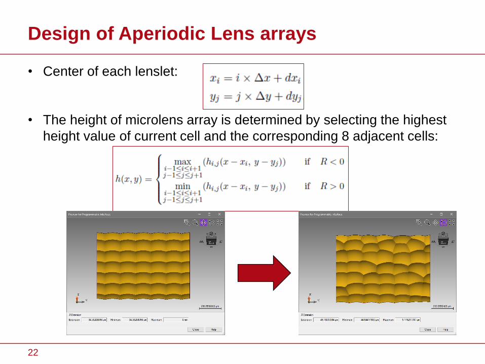
Design of Aperiodic Lens arrays
• Center of each lenslet:
• The height of microlens array is determined by selecting the highest
height value of current cell and the corresponding 8 adjacent cells:
22
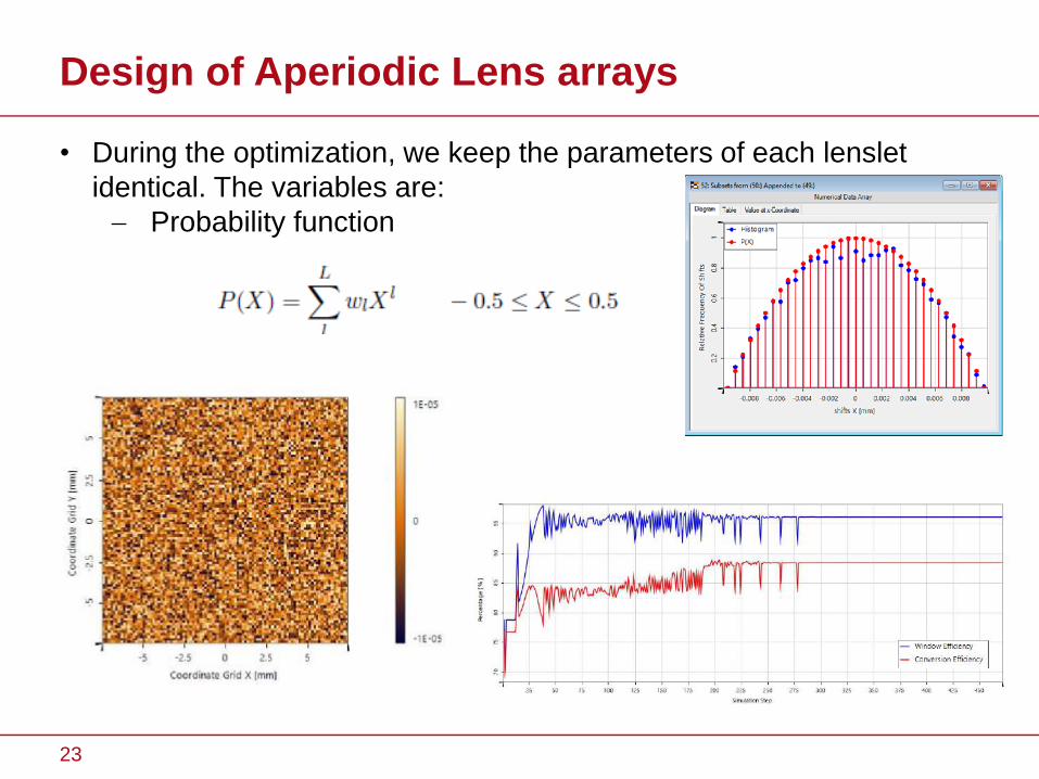
Design of Aperiodic Lens arrays
• During the optimization, we keep the parameters of each lenslet
identical. The variables are:
Probability function
23
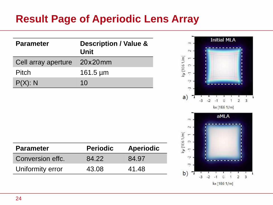
Result Page of Aperiodic Lens Array
24
Parameter Description / Value &
Unit
Cell array aperture 20 x 20 mm
Pitch 161.5 µm
P(X): N 10
Parameter Periodic Aperiodic
Conversion effc. 84.22 84.97
Uniformity error 43.08 41.48
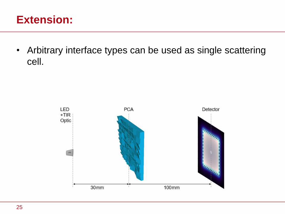
Extension:
• Arbitrary interface types can be used as single scattering
cell.
25
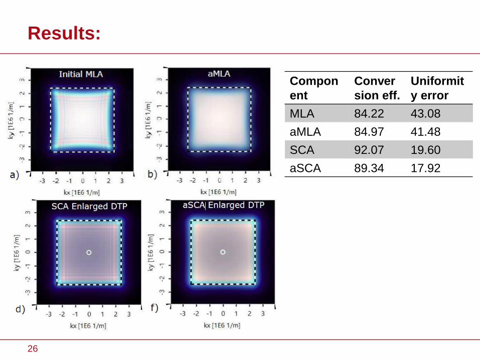
Results:
26
Compon
ent
Conver
sion eff.
Uniformit
y error
MLA 84.22 43.08
aMLA 84.97 41.48
SCA 92.07 19.60
aSCA 89.34 17.92
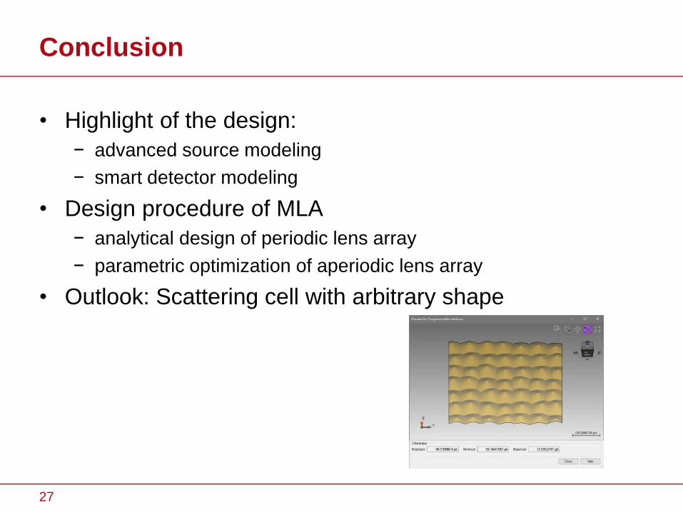
Conclusion
• Highlight of the design:
− advanced source modeling
− smart detector modeling
• Design procedure of MLA
− analytical design of periodic lens array
− parametric optimization of aperiodic lens array
• Outlook: Scattering cell with arbitrary shape
27
Acknowledgement
• Zentrales Innovationsprogramm Mittelstand(ZIM)-
Kooperationsprojecte
28

Thanks for your attention!
29


![Homogenization of Metric Hamilton- Jacobi equations · lation is that it leads to a more tractable homogenization problem: the homogenization of Finsler metrics [2]. 1.1. Particle](https://img.pdfslide.net/doc/110x75/5edcc50fad6a402d666794e4/homogenization-of-metric-hamilton-jacobi-equations-lation-is-that-it-leads-to-a.jpg)