Embed Size (px)
Citation preview
Shared Infrastructure Architecture for GovernmentEDCS-543247
November 2006
Corporate HeadquartersCisco Systems, Inc.170 West Tasman DriveSan Jose, CA 95134-1706 USAhttp://www.cisco.comTel: 408 526-4000
800 553-NETS (6387)Fax: 408 526-4100

THE SPECIFICATIONS AND INFORMATION REGARDING THE PRODUCTS IN THIS MANUAL ARE SUBJECT TO CHANGE WITHOUT NOTICE. ALL STATEMENTS, INFORMATION, AND RECOMMENDATIONS IN THIS MANUAL ARE BELIEVED TO BE ACCURATE BUT ARE PRESENTED WITHOUT WARRANTY OF ANY KIND, EXPRESS OR IMPLIED. USERS MUST TAKE FULL RESPONSIBILITY FOR THEIR APPLICATION OF ANY PRODUCTS.
THE SOFTWARE LICENSE AND LIMITED WARRANTY FOR THE ACCOMPANYING PRODUCT ARE SET FORTH IN THE INFORMATION PACKET THAT SHIPPED WITH THE PRODUCT AND ARE INCORPORATED HEREIN BY THIS REFERENCE. IF YOU ARE UNABLE TO LOCATE THE SOFTWARE LICENSE OR LIMITED WARRANTY, CONTACT YOUR CISCO REPRESENTATIVE FOR A COPY.
The Cisco implementation of TCP header compression is an adaptation of a program developed by the University of California, Berkeley (UCB) as part of UCB’s public domain version of the UNIX operating system. All rights reserved. Copyright © 1981, Regents of the University of California.
NOTWITHSTANDING ANY OTHER WARRANTY HEREIN, ALL DOCUMENT FILES AND SOFTWARE OF THESE SUPPLIERS ARE PROVIDED “AS IS” WITH ALL FAULTS. CISCO AND THE ABOVE-NAMED SUPPLIERS DISCLAIM ALL WARRANTIES, EXPRESSED OR IMPLIED, INCLUDING, WITHOUT LIMITATION, THOSE OF MERCHANTABILITY, FITNESS FOR A PARTICULAR PURPOSE AND NONINFRINGEMENT OR ARISING FROM A COURSE OF DEALING, USAGE, OR TRADE PRACTICE.
IN NO EVENT SHALL CISCO OR ITS SUPPLIERS BE LIABLE FOR ANY INDIRECT, SPECIAL, CONSEQUENTIAL, OR INCIDENTAL DAMAGES, INCLUDING, WITHOUT LIMITATION, LOST PROFITS OR LOSS OR DAMAGE TO DATA ARISING OUT OF THE USE OR INABILITY TO USE THIS MANUAL, EVEN IF CISCO OR ITS SUPPLIERS HAVE BEEN ADVISED OF THE POSSIBILITY OF SUCH DAMAGES.
Any Internet Protocol (IP) addresses used in this document are not intended to be actual addresses. Any examples, command display output, and figures included in the document are shown for illustrative purposes only. Any use of actual IP addresses in illustrative content is unintentional and coincidental.
Shared Infrastructure Architecture for Government © 2006 Cisco Systems, Inc. All rights reserved.
CCSP, CCVP, the Cisco Square Bridge logo, Follow Me Browsing, and StackWise are trademarks of Cisco Systems, Inc.; Changing the Way We Work, Live, Play, and Learn, and iQuick Study are service marks of Cisco Systems, Inc.; and Access Registrar, Aironet, BPX, Catalyst, CCDA, CCDP, CCIE, CCIP, CCNA, CCNP, Cisco, the Cisco Certified Internetwork Expert logo, Cisco IOS, Cisco Press, Cisco Systems, Cisco Systems Capital, the Cisco Systems logo, Cisco Unity, Enterprise/Solver, EtherChannel, EtherFast, EtherSwitch, Fast Step, FormShare, GigaDrive, GigaStack, HomeLink, Internet Quotient, IOS, IP/TV, iQ Expertise, the iQ logo, iQ Net Readiness Scorecard, LightStream, Linksys, MeetingPlace, MGX, the Networkers logo, Networking Academy, Network Registrar, Packet, PIX, Post-Routing, Pre-Routing, ProConnect, RateMUX, ScriptShare, SlideCast, SMARTnet, The Fastest Way to Increase Your Internet Quotient, and TransPath are registered trademarks of Cisco Systems, Inc. and/or its affiliates in the United States and certain other countries.
All other trademarks mentioned in this document or Website are the property of their respective owners. The use of the word partner does not imply a partnership relationship between Cisco and any other company. (0601R)

Contents
Preface xi
Executive Summary xi
Disclaimer xiii
C H A P T E R 1 Shared Infrastructure 1-1
Introduction 1-1
Example—Agriculture Department 1-3
Access Control 1-3
Path Isolation 1-4
Services Edge 1-5
C H A P T E R 2 Shared Data Center Services 2-1
Introduction 2-1
Data Center Architecture 2-4
Building Blocks 2-6
Network Areas 2-6
Network DNA 2-7
Network Virtualization and Segmentation 2-8
Network Intelligence 2-13
Network Security 2-16
Server Fabric 2-18
SAN Fabric 2-18
Summary 2-18
C H A P T E R 3 Shared Security Services 3-1
Introduction 3-1
Shared Infrastructure Security Risks 3-2
Network Security in a Secure Segment 3-3
C H A P T E R 4 Shared Infrastructure Network Management 4-1
Introduction 4-1
Demarcation Point 4-2
Administration 4-2
Service-Level Agreements 4-2
Why Are SLAs Important? 4-2
Compliance 4-2
Network Management Architecture 4-3
iiiShared Infrastructure Architecture for Government
EDCS-543247

Contents
What Is a DCN? 4-3
Building a Foundation for an Optical Transport Network with DCN 4-4
DCN Three-Tiered Architecture 4-6
C H A P T E R 5 Summary 5-1
Phased Approach 5-1
A P P E N D I X A Design Considerations A-1
Introduction A-1
VRF Technology Overview A-1
Routing Protocols A-5
IGMP Snooping A-6
Distribution Trees A-7
Tree Structure A-7
Distribution of Receivers A-8
IP Multicast Routing Protocols A-9
Protocol Independent Multicast (PIM) A-9
Protocol Independent Multicast-Sparse Mode (PIM-SM) A-9
Protocol Independent Multicast-Dense Mode (PIM-DM) A-9
Bidirectional PIM (bidir-PIM) A-10
Protocol Dependent Multicast Choices A-11
Reverse Path Forwarding (RPF) A-12
Interdomain Multicast Routing A-12
Multicast Border Gateway Protocol A-12
Multicast Source Discovery Protocol A-12
Reliable Multicast—Pragmatic General Multicast A-13
Mobility A-13
MPLS A-14
Goals in QoS A-15
IntServ A-18
DiffServ A-18
IntServ or DiffServ—Which to Deploy? A-18
Packet Marking A-19
PHBs A-19
Default PHB (Defined in RFC-2474) A-19
Class-Selector PHBs (Defined in RFC-2474) A-19
Expedited Forwarding PHB (Defined in RFC-2598) A-20
Assured Forwarding PHB (Defined in RFC-2597) A-20
DiffServ Issues—The Challenges A-20
ivShared Infrastructure Architecture for Government
EDCS-543247
Contents
PEP A-22
Hierarchical Network Design A-22
Scalability of a Hierarchical Design A-22
Core Layer A-24
Distribution Layer A-25
Access Layer A-26
Considerations A-26
Summary A-27
A P P E N D I X B Security Terminology and Standards B-1
Security Terminology B-1
Security Standards B-1
COBIT B-3
ISO/IEC 17799 B-3
vShared Infrastructure Architecture for Government
EDCS-543247

Contents
viShared Infrastructure Architecture for Government
EDCS-543247
F I G U R E S
Figure 1 Sharing Applications and Infrastructure Across Agency Boundaries xii
Figure 1-1 Functional Areas 1-2
Figure 1-2 Internet Edge Design 1-6
Figure 1-3 Accessing Shared Services 1-7
Figure 1-4 Internet Edge with Virtual Firewall 1-8
Figure 2-1 Dedicated Data Center Architecture 2-2
Figure 2-2 Virtualized Data Center Architecture 2-3
Figure 2-3 Data Center Architecture 2-5
Figure 2-4 Layer 2 Access 2-6
Figure 2-5 Layer 3 Access 2-7
Figure 2-6 Network Virtualization and Segmentation 2-9
Figure 2-7 Access Control, Path Isolation, and Services Edge 2-10
Figure 2-8 Scenario 2—Continuity of Operations 2-12
Figure 2-9 Scenario 3—Site Expansion 2-15
Figure 2-10 Scenario 4—Protection from Data Center Attacks 2-17
Figure 3-1 Security Is Process, Not Products 3-1
Figure 3-2 Threat Capabilities—More Dangerous and Easier to Use 3-2
Figure 4-1 DCN 4-4
Figure 4-2 DCN Optical Transport Network 4-5
Figure 4-3 DCN Three-Tiered Architecture 4-6
Figure 4-4 Cisco’s DCN Architecture 4-7
Figure 5-1 Phased Approach 5-1
Figure 5-2 Business Value of Shared Infrastructure Approach 5-4
Figure A-1 Virtualization of a Layer 3 Network Device A-2
Figure A-2 Network Virtualization A-3
Figure A-3 Segmentation Through the Enterprise Network A-4
Figure A-4 Source Trees and Shared Trees A-8
Figure A-5 PIM-Dense Mode A-10
Figure A-6 Hierarchical Network Structure—Logical Perspective A-22
Figure A-7 Hierarchical Architecture A-24
viiShared Infrastructure Architecture for Government
EDCS-543247

Figures
viiiShared Infrastructure Architecture for Government
EDCS-543247
T A B L E S
Table 2-1 Fundamental Elements of Virtualization and Segmentation 2-10
Table 2-2 Network Intelligence Capabilities 2-13
Table 3-1 Additional Security 3-4
Table 5-1 Phased Approach 5-2
Table A-1 Congestion Avoidance and Congestion Control A-16
ixShared Infrastructure Architecture for Government
EDCS-543247

Tables
xShared Infrastructure Architecture for Government
EDCS-543247
Preface
Executive SummaryAs governments worldwide pursue online initiatives to reduce ongoing operating costs and become more responsive to citizen needs, they are increasingly turning to the flexibility of IP networks to deliver converged voice, video, and data services. These same networks serve as the foundation for advanced Unified Communications capabilities that can improve intra- and inter-agency collaboration as well as serve as a platform for shared communications services within and between agencies. The move is clear. Market research firm INPUT anticipates that by 2010, the U.S. federal government will be spending $17.6 billion on IT outsourcing—one of the fastest-growing federal market segments over the past several years. The main driver is sharing IT assets among agencies and departments.
Similarly, data from research analyst Kable revealed that European governments spend an estimated 25 percent of overall expenses on the data center alone. Limited inter-agency sharing of common IT infrastructure is a key contributor to the high cost of running government. Again, in the United States, the Office of Management and Budget estimates that the U.S. Government could save $5 billion if it began to share common government services across different agencies.
Employing a service-oriented network architecture (SONA), Cisco® Connected Government offers a multiphase approach for agencies to optimize application delivery, business processes, and investments. Drawing from global best practices, SONA incorporates Cisco and Cisco partner solutions, services, and architectural experience working with governments around the world.
To assist customers with the objective of improving interagency IT infrastructure sharing in the United States, Asia Pacific, Canada, and Europe, Cisco has assembled a set of best practices and design considerations that address:
• Shared Infrastructure
• Shared Data Center Services
• Shared Security Services
• Shared Infrastructure Network Management
xiShared Infrastructure Architecture for Government
EDCS-543247

PrefaceExecutive Summary
Figure 1 Sharing Applications and Infrastructure Across Agency Boundaries
As Figure 1 illustrates, a properly designed infrastructure is able to effectively segment information by community of interest as the information traverses the network. The data at rest is also segmented using virtual storage area networks (VSANs) that effectively separate SANs into what appear to be physically separate disk storage systems. The overall objective of the shared infrastructure is to deliver cost and efficiency while maintaining control for the community of interest using the shared infrastructure.
Costs are reduced because multiple agencies can leverage a common investment. Additionally, the provider of services can maximize utilization of the shared network and data center assets by turning dedicated resources assigned to each application within each group into a shared pool of resources that can be dynamically allocated based on application and business needs.
Efficiency is improved because the single shared infrastructure is easier to manage and re-configure to conform to the changing needs of the government and the constituents it serves. By leveraging a common shared infrastructure, agencies can easily share applications and information based on policy and application demand, allowing new applications to be built based on constituent needs instead of government hierarchy.
Data Center Headquarters
Agricultural DeptFarm ServicesFood and Safety
Agricultural DeptFarm ServicesFood and Safety
ServerConsolidation
WebServers
Data Center Branch
WebServers
DWDMNetwork
IP
RemoteWorker
IP
VPN
IPWAN
1576
61
xiiShared Infrastructure Architecture for Government
EDCS-543247

PrefaceDisclaimer
DisclaimerThe architectures described in this paper provide options that are achievable with the technology, however regulations may govern what can be deployed. Before implementing these architectures, specific regulations that apply to your agency should be thoroughly evaluated.
Caution All references to agencies and departments in this paper are fictitious and are used only for explanatory purposes. Any similarities to existing agencies or departments are purely coincidental and should not be taken as fact.
xiiiShared Infrastructure Architecture for Government
EDCS-543247

PrefaceDisclaimer
xivShared Infrastructure Architecture for Government
EDCS-543247
Shared InfrEDCS-543247
C H A P T E R 1
Shared InfrastructureIntroductionAgencies that upgrade to a shared infrastructure can enable greater productivity, enhance collaboration, and improve service. By implementing a comprehensive architecture for shared network services, agencies can:
• Control and enhance network access for their employees, customers, partners, vendors, contractors, and guests
• Reduce IT support resources and expenses
• Keep the traffic of the various user groups securely separated from one another
• Have full auditing of network usage
The need for shared infrastructures has developed as the needs of businesses have evolved. At one time, it was sufficient to provide employees with a workspace, computer, and telephone. Today, agencies frequently have multiple, widely-dispersed offices, share vast amounts of data internally and externally with other agencies, and must be able to communicate quickly and reliably. Employees require full connectivity to a variety of public and private resources without compromising the security of the host network.
The main technical requirements for a complete shared infrastructure architecture are:
• Remote access from branch or home locations and the capability to establish a VPN connection to the network when traveling
• Logical isolation of traffic from the appropriate users
• Authentication and logging capabilities
• Accounting, filtering, content checking, and security
• Seamless support for both wired and wireless access
An example of a traditional architecture to connect branch offices to the headquarters leverages a privately-owned WAN, leased lines, ATM networks, and Frame Relay connections. The requirement to reduce costs has, in recent years, led to the adoption of a new type of connectivity between branch locations and headquarters. In these deployments, VPN architectures (mostly IPSec) are implemented to leverage the public Internet.
The goals of this architecture are to:
• Identify a user as a guest or employee and assign them to the appropriate segment
• Isolate the guest traffic from the rest of the network while providing Internet access
• Provide network services to enterprise visitors, including the following:
1-1astructure Architecture for Government
Chapter 1 Shared InfrastructureIntroduction
– Network services—DHCP, DNS, and Internet
– Security services—Firewalls, load balancers, intrusion detection systems (IDSs), accounting, and monitoring
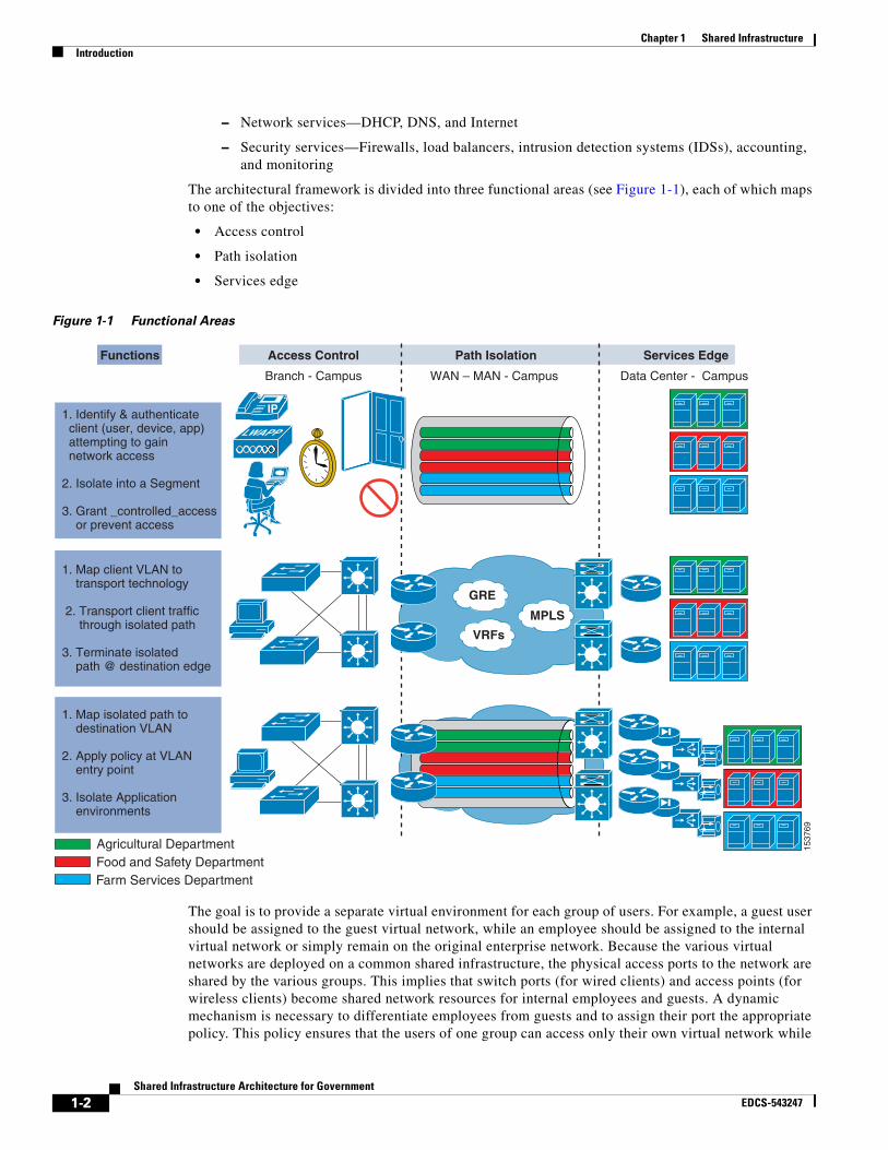
The architectural framework is divided into three functional areas (see Figure 1-1), each of which maps to one of the objectives:
• Access control
• Path isolation
• Services edge
Figure 1-1 Functional Areas
The goal is to provide a separate virtual environment for each group of users. For example, a guest user should be assigned to the guest virtual network, while an employee should be assigned to the internal virtual network or simply remain on the original enterprise network. Because the various virtual networks are deployed on a common shared infrastructure, the physical access ports to the network are shared by the various groups. This implies that switch ports (for wired clients) and access points (for wireless clients) become shared network resources for internal employees and guests. A dynamic mechanism is necessary to differentiate employees from guests and to assign their port the appropriate policy. This policy ensures that the users of one group can access only their own virtual network while
1537
69
LWAPP1. Identify & authenticate client (user, device, app) attempting to gain network access
2. Isolate into a Segment
3. Grant _controlled_access or prevent access
1. Map client VLAN to transport technology
2. Transport client traffic through isolated path
3. Terminate isolated path @ destination edge
1. Map isolated path to destination VLAN
2. Apply policy at VLAN entry point
3. Isolate Application environments
IP
GRE
VRFs
MPLS
Functions Access Control Path Isolation Services Edge
Branch - Campus WAN – MAN - Campus Data Center - Campus
Agricultural DepartmentFood and Safety DepartmentFarm Services Department
1-2Shared Infrastructure Architecture for Government
EDCS-543247
Chapter 1 Shared InfrastructureExample—Agriculture Department
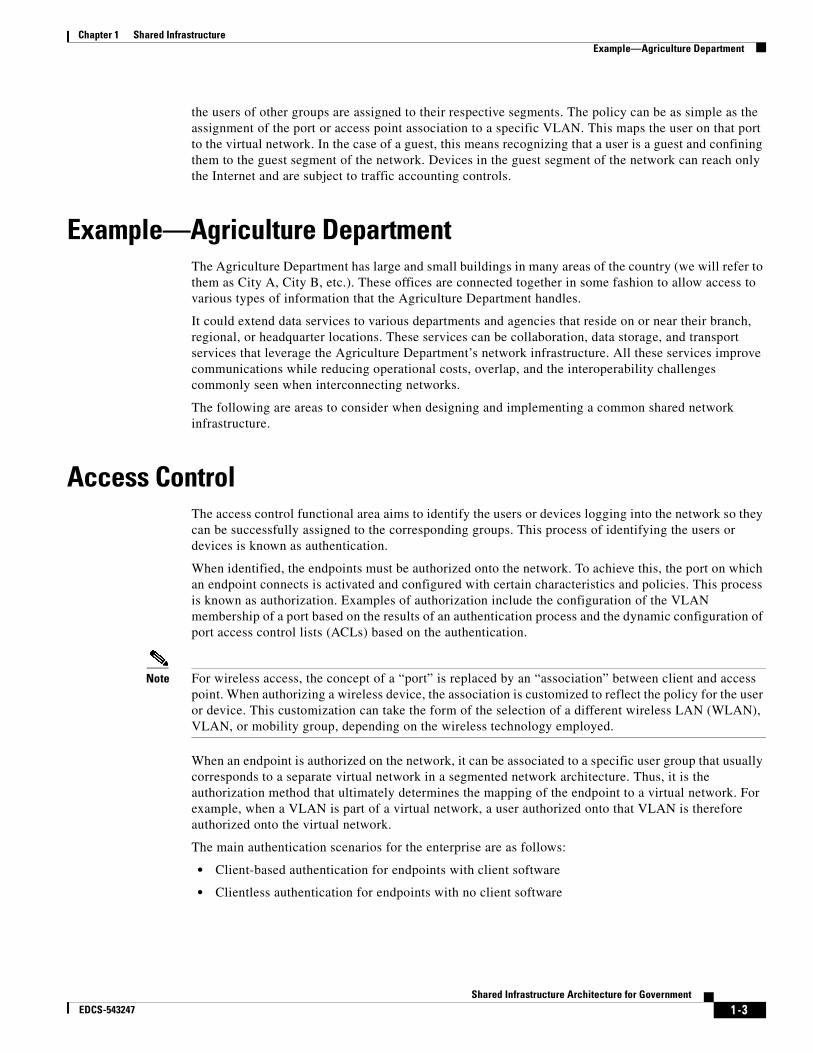
the users of other groups are assigned to their respective segments. The policy can be as simple as the assignment of the port or access point association to a specific VLAN. This maps the user on that port to the virtual network. In the case of a guest, this means recognizing that a user is a guest and confining them to the guest segment of the network. Devices in the guest segment of the network can reach only the Internet and are subject to traffic accounting controls.
Example—Agriculture DepartmentThe Agriculture Department has large and small buildings in many areas of the country (we will refer to them as City A, City B, etc.). These offices are connected together in some fashion to allow access to various types of information that the Agriculture Department handles.
It could extend data services to various departments and agencies that reside on or near their branch, regional, or headquarter locations. These services can be collaboration, data storage, and transport services that leverage the Agriculture Department’s network infrastructure. All these services improve communications while reducing operational costs, overlap, and the interoperability challenges commonly seen when interconnecting networks.
The following are areas to consider when designing and implementing a common shared network infrastructure.
Access ControlThe access control functional area aims to identify the users or devices logging into the network so they can be successfully assigned to the corresponding groups. This process of identifying the users or devices is known as authentication.
When identified, the endpoints must be authorized onto the network. To achieve this, the port on which an endpoint connects is activated and configured with certain characteristics and policies. This process is known as authorization. Examples of authorization include the configuration of the VLAN membership of a port based on the results of an authentication process and the dynamic configuration of port access control lists (ACLs) based on the authentication.
Note For wireless access, the concept of a “port” is replaced by an “association” between client and access point. When authorizing a wireless device, the association is customized to reflect the policy for the user or device. This customization can take the form of the selection of a different wireless LAN (WLAN), VLAN, or mobility group, depending on the wireless technology employed.
When an endpoint is authorized on the network, it can be associated to a specific user group that usually corresponds to a separate virtual network in a segmented network architecture. Thus, it is the authorization method that ultimately determines the mapping of the endpoint to a virtual network. For example, when a VLAN is part of a virtual network, a user authorized onto that VLAN is therefore authorized onto the virtual network.
The main authentication scenarios for the enterprise are as follows:
• Client-based authentication for endpoints with client software
• Clientless authentication for endpoints with no client software
1 -3Shared Infrastructure Architecture for Government
EDCS-543247
Chapter 1 Shared InfrastructurePath Isolation
The current state of technology provides broad support for VLAN assignment as an authorization alternative. In the cases where policy changes based on authentication are required and only VLAN assignment authorization is available, a static assignment of a policy to a VLAN provides the required linkage between the user authorization and the necessary policy. In effect, the policy is applied to the VLAN because users are subject to the policy when authorized onto the VLAN.
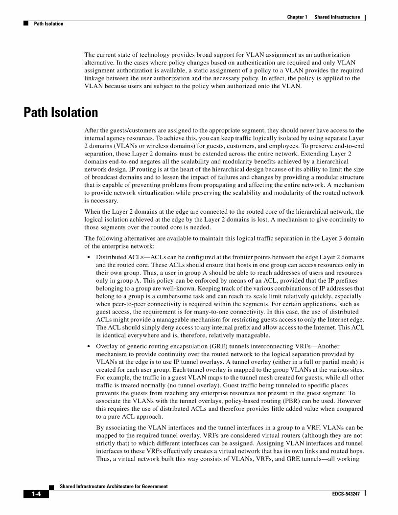
Path IsolationAfter the guests/customers are assigned to the appropriate segment, they should never have access to the internal agency resources. To achieve this, you can keep traffic logically isolated by using separate Layer 2 domains (VLANs or wireless domains) for guests, customers, and employees. To preserve end-to-end separation, those Layer 2 domains must be extended across the entire network. Extending Layer 2 domains end-to-end negates all the scalability and modularity benefits achieved by a hierarchical network design. IP routing is at the heart of the hierarchical design because of its ability to limit the size of broadcast domains and to lessen the impact of failures and changes by providing a modular structure that is capable of preventing problems from propagating and affecting the entire network. A mechanism to provide network virtualization while preserving the scalability and modularity of the routed network is necessary.
When the Layer 2 domains at the edge are connected to the routed core of the hierarchical network, the logical isolation achieved at the edge by the Layer 2 domains is lost. A mechanism to give continuity to those segments over the routed core is needed.
The following alternatives are available to maintain this logical traffic separation in the Layer 3 domain of the enterprise network:
• Distributed ACLs—ACLs can be configured at the frontier points between the edge Layer 2 domains and the routed core. These ACLs should ensure that hosts in one group can access resources only in their own group. Thus, a user in group A should be able to reach addresses of users and resources only in group A. This policy can be enforced by means of an ACL, provided that the IP prefixes belonging to a group are well-known. Keeping track of the various combinations of IP addresses that belong to a group is a cumbersome task and can reach its scale limit relatively quickly, especially when peer-to-peer connectivity is required within the segments. For certain applications, such as guest access, the requirement is for many-to-one connectivity. In this case, the use of distributed ACLs might provide a manageable mechanism for restricting guests access to only the Internet edge. The ACL should simply deny access to any internal prefix and allow access to the Internet. This ACL is identical everywhere and is, therefore, relatively manageable.
• Overlay of generic routing encapsulation (GRE) tunnels interconnecting VRFs—Another mechanism to provide continuity over the routed network to the logical separation provided by VLANs at the edge is to use IP tunnel overlays. A tunnel overlay (either in a full or partial mesh) is created for each user group. Each tunnel overlay is mapped to the group VLANs at the various sites. For example, the traffic in a guest VLAN maps to the tunnel mesh created for guests, while all other traffic is treated normally (no tunnel overlay). Guest traffic being tunneled to specific places prevents the guests from reaching any enterprise resources not present in the guest segment. To associate the VLANs with the tunnel overlays, policy-based routing (PBR) can be used. However this requires the use of distributed ACLs and therefore provides little added value when compared to a pure ACL approach.
By associating the VLAN interfaces and the tunnel interfaces in a group to a VRF, VLANs can be mapped to the required tunnel overlay. VRFs are considered virtual routers (although they are not strictly that) to which different interfaces can be assigned. Assigning VLAN interfaces and tunnel interfaces to these VRFs effectively creates a virtual network that has its own links and routed hops. Thus, a virtual network built this way consists of VLANs, VRFs, and GRE tunnels—all working
1-4Shared Infrastructure Architecture for Government
EDCS-543247
Chapter 1 Shared InfrastructureServices Edge
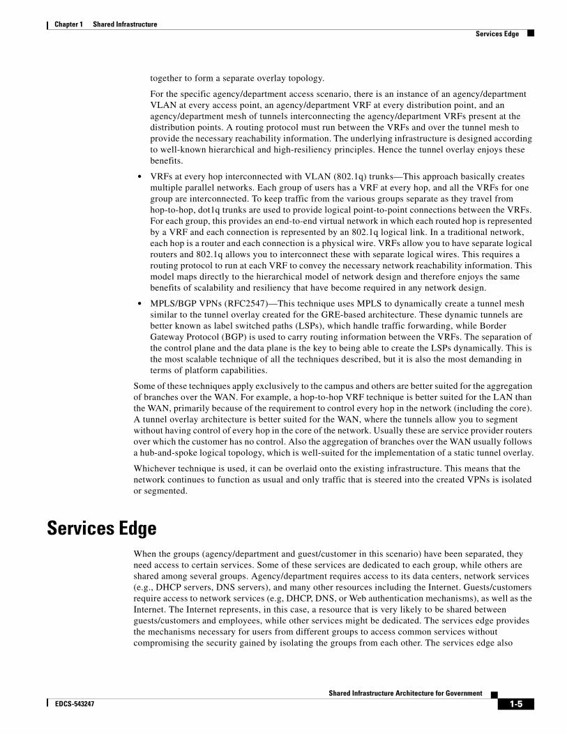
together to form a separate overlay topology.
For the specific agency/department access scenario, there is an instance of an agency/department VLAN at every access point, an agency/department VRF at every distribution point, and an agency/department mesh of tunnels interconnecting the agency/department VRFs present at the distribution points. A routing protocol must run between the VRFs and over the tunnel mesh to provide the necessary reachability information. The underlying infrastructure is designed according to well-known hierarchical and high-resiliency principles. Hence the tunnel overlay enjoys these benefits.
• VRFs at every hop interconnected with VLAN (802.1q) trunks—This approach basically creates multiple parallel networks. Each group of users has a VRF at every hop, and all the VRFs for one group are interconnected. To keep traffic from the various groups separate as they travel from hop-to-hop, dot1q trunks are used to provide logical point-to-point connections between the VRFs. For each group, this provides an end-to-end virtual network in which each routed hop is represented by a VRF and each connection is represented by an 802.1q logical link. In a traditional network, each hop is a router and each connection is a physical wire. VRFs allow you to have separate logical routers and 802.1q allows you to interconnect these with separate logical wires. This requires a routing protocol to run at each VRF to convey the necessary network reachability information. This model maps directly to the hierarchical model of network design and therefore enjoys the same benefits of scalability and resiliency that have become required in any network design.
• MPLS/BGP VPNs (RFC2547)—This technique uses MPLS to dynamically create a tunnel mesh similar to the tunnel overlay created for the GRE-based architecture. These dynamic tunnels are better known as label switched paths (LSPs), which handle traffic forwarding, while Border Gateway Protocol (BGP) is used to carry routing information between the VRFs. The separation of the control plane and the data plane is the key to being able to create the LSPs dynamically. This is the most scalable technique of all the techniques described, but it is also the most demanding in terms of platform capabilities.
Some of these techniques apply exclusively to the campus and others are better suited for the aggregation of branches over the WAN. For example, a hop-to-hop VRF technique is better suited for the LAN than the WAN, primarily because of the requirement to control every hop in the network (including the core). A tunnel overlay architecture is better suited for the WAN, where the tunnels allow you to segment without having control of every hop in the core of the network. Usually these are service provider routers over which the customer has no control. Also the aggregation of branches over the WAN usually follows a hub-and-spoke logical topology, which is well-suited for the implementation of a static tunnel overlay.
Whichever technique is used, it can be overlaid onto the existing infrastructure. This means that the network continues to function as usual and only traffic that is steered into the created VPNs is isolated or segmented.
Services EdgeWhen the groups (agency/department and guest/customer in this scenario) have been separated, they need access to certain services. Some of these services are dedicated to each group, while others are shared among several groups. Agency/department requires access to its data centers, network services (e.g., DHCP servers, DNS servers), and many other resources including the Internet. Guests/customers require access to network services (e.g, DHCP, DNS, or Web authentication mechanisms), as well as the Internet. The Internet represents, in this case, a resource that is very likely to be shared between guests/customers and employees, while other services might be dedicated. The services edge provides the mechanisms necessary for users from different groups to access common services without compromising the security gained by isolating the groups from each other. The services edge also
1-5Shared Infrastructure Architecture for Government
EDCS-543247
Chapter 1 Shared InfrastructureServices Edge
provides access to services that are dedicated to each specific group. To achieve this, it provides logical connectivity and security mechanisms over shared facilities, such as firewalls, load balancers, VPN concentrators, or even IDSs.
The virtualization of the enterprise network allows for the creation of a separate logical network that is placed on top of the physical infrastructure. The default state of these virtual networks (VPNs) is to be totally isolated from each other, in this way simulating separate physical networks.
The default behavior of a virtual network may be changed for the following reasons:
• To allow inter-VPN communications; this must be done in a safe and controlled manner.
• To allow the various VPNs to share certain services; the most common is Internet access, but there are also network services, such as DHCP and DNS, and server farms.
To allow secure communication between each VPN and the Internet, it is necessary to create unique points of ingress and egress to each defined virtual network. This can be achieved by configuring the routing inside of each VPN to forward traffic destined outside the VPN to a specific gateway. When traffic reaches this gateway, it can be controlled by means of ACLs, firewalls, IDSs, or any other in-band security mechanisms that are considered necessary.
This is the equivalent of treating each VPN as if it were a physically separate network. Separate networks connecting to a common resource must have a security device headend to control access to the network.
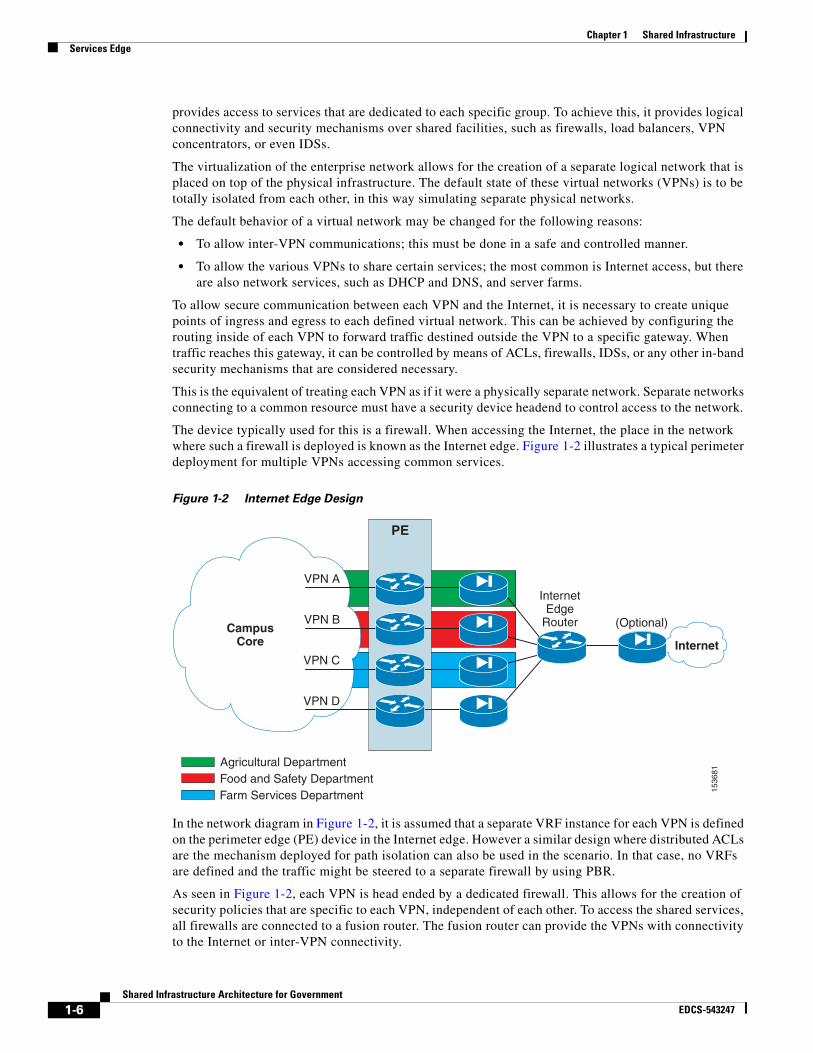
The device typically used for this is a firewall. When accessing the Internet, the place in the network where such a firewall is deployed is known as the Internet edge. Figure 1-2 illustrates a typical perimeter deployment for multiple VPNs accessing common services.
Figure 1-2 Internet Edge Design
In the network diagram in Figure 1-2, it is assumed that a separate VRF instance for each VPN is defined on the perimeter edge (PE) device in the Internet edge. However a similar design where distributed ACLs are the mechanism deployed for path isolation can also be used in the scenario. In that case, no VRFs are defined and the traffic might be steered to a separate firewall by using PBR.
As seen in Figure 1-2, each VPN is head ended by a dedicated firewall. This allows for the creation of security policies that are specific to each VPN, independent of each other. To access the shared services, all firewalls are connected to a fusion router. The fusion router can provide the VPNs with connectivity to the Internet or inter-VPN connectivity.
CampusCore Internet
VPN A
PE
1536
81
InternetEdge
RouterVPN B
VPN C
VPN D
(Optional)
Agricultural DepartmentFood and Safety DepartmentFarm Services Department
1-6Shared Infrastructure Architecture for Government
EDCS-543247
Chapter 1 Shared InfrastructureServices Edge
The use of a fusion router raises two main concerns:
• Potential traffic leaking between VPNs
• Risk of routes from one VPN being announced to another VPN
Having dedicated per-VPN firewalls prevents the leaking of traffic between VPNs through the fusion router by allowing only established connections to return through the VPN perimeter. It is important to configure the routing on the fusion device so that it does not advertise the routes from one VPN to another VPN.
Figure 1-2 shows an additional firewall separating the fusion area from the Internet. This firewall is optional and is used to keep common services or transit traffic in the fusion area protected from the Internet.
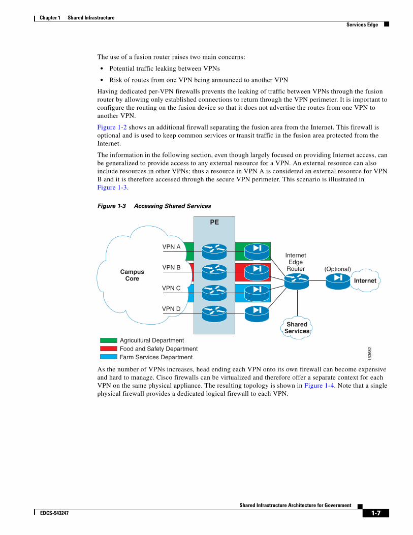
The information in the following section, even though largely focused on providing Internet access, can be generalized to provide access to any external resource for a VPN. An external resource can also include resources in other VPNs; thus a resource in VPN A is considered an external resource for VPN B and it is therefore accessed through the secure VPN perimeter. This scenario is illustrated in Figure 1-3.
Figure 1-3 Accessing Shared Services
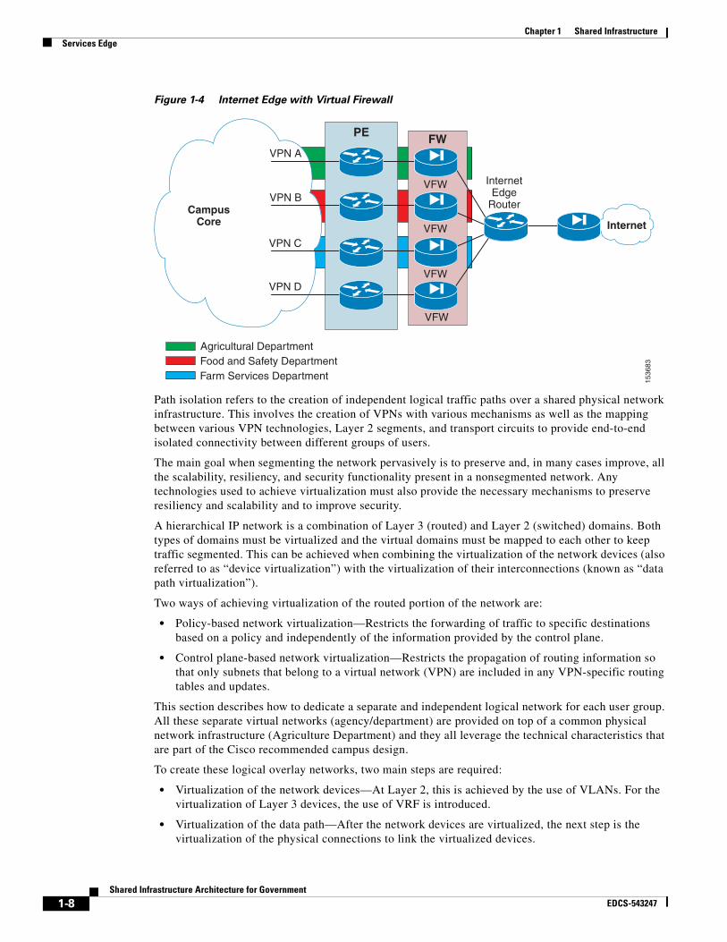
As the number of VPNs increases, head ending each VPN onto its own firewall can become expensive and hard to manage. Cisco firewalls can be virtualized and therefore offer a separate context for each VPN on the same physical appliance. The resulting topology is shown in Figure 1-4. Note that a single physical firewall provides a dedicated logical firewall to each VPN.
CampusCore Internet
VPN A
PE
1536
82
InternetEdge
RouterVPN B
VPN C
VPN D
(Optional)
SharedServices
Agricultural DepartmentFood and Safety DepartmentFarm Services Department
1-7Shared Infrastructure Architecture for Government
EDCS-543247
Chapter 1 Shared InfrastructureServices Edge
Figure 1-4 Internet Edge with Virtual Firewall
Path isolation refers to the creation of independent logical traffic paths over a shared physical network infrastructure. This involves the creation of VPNs with various mechanisms as well as the mapping between various VPN technologies, Layer 2 segments, and transport circuits to provide end-to-end isolated connectivity between different groups of users.
The main goal when segmenting the network pervasively is to preserve and, in many cases improve, all the scalability, resiliency, and security functionality present in a nonsegmented network. Any technologies used to achieve virtualization must also provide the necessary mechanisms to preserve resiliency and scalability and to improve security.
A hierarchical IP network is a combination of Layer 3 (routed) and Layer 2 (switched) domains. Both types of domains must be virtualized and the virtual domains must be mapped to each other to keep traffic segmented. This can be achieved when combining the virtualization of the network devices (also referred to as “device virtualization”) with the virtualization of their interconnections (known as “data path virtualization”).
Two ways of achieving virtualization of the routed portion of the network are:
• Policy-based network virtualization—Restricts the forwarding of traffic to specific destinations based on a policy and independently of the information provided by the control plane.
• Control plane-based network virtualization—Restricts the propagation of routing information so that only subnets that belong to a virtual network (VPN) are included in any VPN-specific routing tables and updates.
This section describes how to dedicate a separate and independent logical network for each user group. All these separate virtual networks (agency/department) are provided on top of a common physical network infrastructure (Agriculture Department) and they all leverage the technical characteristics that are part of the Cisco recommended campus design.
To create these logical overlay networks, two main steps are required:
• Virtualization of the network devices—At Layer 2, this is achieved by the use of VLANs. For the virtualization of Layer 3 devices, the use of VRF is introduced.
• Virtualization of the data path—After the network devices are virtualized, the next step is the virtualization of the physical connections to link the virtualized devices.
FW
VFW
CampusCore Internet
VPN A
PE
1536
83
InternetEdge
RouterVPN B
VPN C
VPN D
VFW
VFW
VFW
Agricultural DepartmentFood and Safety DepartmentFarm Services Department
1-8Shared Infrastructure Architecture for Government
EDCS-543247

Chapter 1 Shared InfrastructureServices Edge
For an overview of VRF, refer to Design Considerations.
1-9Shared Infrastructure Architecture for Government
EDCS-543247

Chapter 1 Shared InfrastructureServices Edge
1-10Shared Infrastructure Architecture for Government
EDCS-543247
Shared InfrEDCS-543247
C H A P T E R 2
Shared Data Center ServicesIntroductionData centers are evolving and government agencies that focus on shared infrastructure architectures can benefit from this evolution. Data centers house many critical assets for government agencies, including data storage systems, applications, and servers that support day-to-day operations. Traditionally, these data centers housed mainframe computers, then client and server systems. Over several decades of build outs, data centers became overly complex, at times underused and exhausting physical resources such as heat, space, and power. However these expansions also provided for scalability, reliability, and availability. As the shared infrastructure architecture for data centers is designed, these shortcomings must be mitigated while preserving the positive critical attributes.
Cost is the most critical factor driving data center consolidation because as data centers expanded to meet agency requirements, with more and more servers, applications, and storage devices, they became increasingly expensive to support and maintain. Costs include the real estate required to store the equipment, some of which may only be operating at a fraction of its capacity, the power to run the equipment, and the maintenance of the devices. Hence while capital expenditures (CapEx) present the initial financial impact, recurring operating expenses (OpEx) place a huge financial strain on government agencies, particularly when many government agencies maintain their own low-capacity, and inefficient, data centers.
2-1astructure Architecture for Government

Chapter 2 Shared Data Center ServicesIntroduction
Figure 2-1 Dedicated Data Center Architecture
In addition to the challenge of maintaining dedicated infrastructure, high operational expenses may cause agencies to sacrifice the technologies required to keep data centers secure, current with technology, and accessible. For example, in Figure 2-1, Farm Services may not be able to centralize their data center. Its Washington, D.C. location drives up bandwidth utilization at this site, which may at times overwhelm the last-mile connection and create unsatisfactory experiences for remote sites. Furthermore, this department may not have access to the technologies required to make the data center highly secure, which it could be if centralized and managed by a well-trained staff. In addition, many of the components are duplicated across agencies and may be operating at only a fraction of their capabilities.
A shared infrastructure architecture for data center consolidation drives down the cost while updating the technology, and hence becomes attractive on multiple levels. Agencies can reap huge financial benefits so they can redeploy funds to other projects instead of wasting it maintaining an inferior legacy operation.
Agricultural Department (500 employees)
Food and Safety(200 employees)
Farm Services(30 employees)
Farm Services(10 employees)
IP IP IP IP IP IP
IP IP IP
IP IP IP
IP IP IP
Agricultural Department (100 employees)
IP IP IP
Food and Safety(200 employees)
City A
Farm ServicesData Center
City B
Food and Safety Data Center Agriculture Department Data Center
Wide Area Network
1576
68
2-2Shared Infrastructure Architecture for Government
EDCS-543247

Chapter 2 Shared Data Center ServicesIntroduction
Figure 2-2 Virtualized Data Center Architecture
In the shared data center approach of the shared infrastructure architecture, a center of excellence delivers to each agency a uniform set of data center services that are technologically current and much more cost-effective. To accomplish this, the next-generation shared data center must meet these requirements:
• Scalability, availability, and reliability—The consolidation of infrastructure into a shared LAN/WAN environment leads to higher-bandwidth 10 Gigabit Ethernet links in the access and aggregation network, while maintaining a high-availability design to ensure that the data centers are always accessible.
Agricultural Department (500 employees)
Food and Safety(200 employees)
Farm Services(30 employees)
Farm Services(10 employees)
IP IP IP IP IP IP
IP IP IP
IP IP IP
IP IP IP
Agricultural Department (100 employees)
IP IP IP
Food and Safety(200 employees)
Agricultural Department Data Center Food and Safety Data Center Farm Services Data Center
Wide Area Network
1576
69City A City B
Layer 3 Switch
Network Management
Intrusion Prevention
Detector
PIX Firewall
SSL
VPN Concentrator
2-3Shared Infrastructure Architecture for Government
EDCS-543247

Chapter 2 Shared Data Center ServicesData Center Architecture
• Security—An ever-increasing factor in network design is security, requiring both products and a suite of security best practice designs to ensure that the critical assets of data centers can withstand known and day-zero threats.
• Segmentation—Consolidation of data centers translates to secure resource allocation and full utilization of the assets, thereby maximizing the capabilities of the equipment. In a shared environment, segmentation allows multiple agencies to share assets that are partitioned to meet the requirements of each agency.
• Virtualization—With the capacity of the WAN, multiple sites for data centers and agencies can now virtualize more assets into the data center and offload the management of onsite gear. These assets can be located in multiple data centers to provide greater survivability in the event of unforeseen circumstances that might bring down a particular site.
• Intelligence—Different departments have different application requirements that can strain the data center. Intelligent service blades enable application acceleration, increased application security, and methods to simplify the application infrastructure to permit the faster deployment of new application servers.
• Manageability—This center of excellence approach simplifies the management of the data center. With infrastructure segmentation and virtualization bundled with management tools from Cisco and partners, the shared data center architecture drastically reduces agency overhead and streamlines operations.
A shared infrastructure architecture that meets these requirements helps drive down the total cost of ownership while enabling the data center to effectively meet the demands of multiple agencies. This can help address any regulatory or political roadblocks that a consolidation effort might face. Finally, the efficiencies gained not only reduce cost, but enable government agencies to more effectively develop tools to serve their constituents.
Data Center ArchitectureThe shared data center architecture of the shared infrastructure approach can be highly sophisticated. The components of the data center are simplified here to explore the specific requirements of a well-designed shared data center for multiple agencies.
2-4Shared Infrastructure Architecture for Government
EDCS-543247

Chapter 2 Shared Data Center ServicesData Center Architecture
Figure 2-3 Data Center Architecture
• Building blocks:
– Network areas—Core, aggregation, access, and DC interconnect
– Network DNA—Layer 2 and Layer 3 designs, high availability, and clustering
– Network virtualization and segmentation
– Network intelligence
– Network security
• Server fabric
• SAN fabric
CampusCore GE
DC Interconnect
WAN
MetroEthernet
SONET/SDHNetwork
Data CenterCore
Aggregation
Access
Servers
Access
Core
StorageDWDMNetwork
1576
70
2-5Shared Infrastructure Architecture for Government
EDCS-543247
Chapter 2 Shared Data Center ServicesData Center Architecture
Building Blocks
Network Areas
The basis of the data center network can be compartmentalized into the access, aggregation, core, and DC interconnect network.
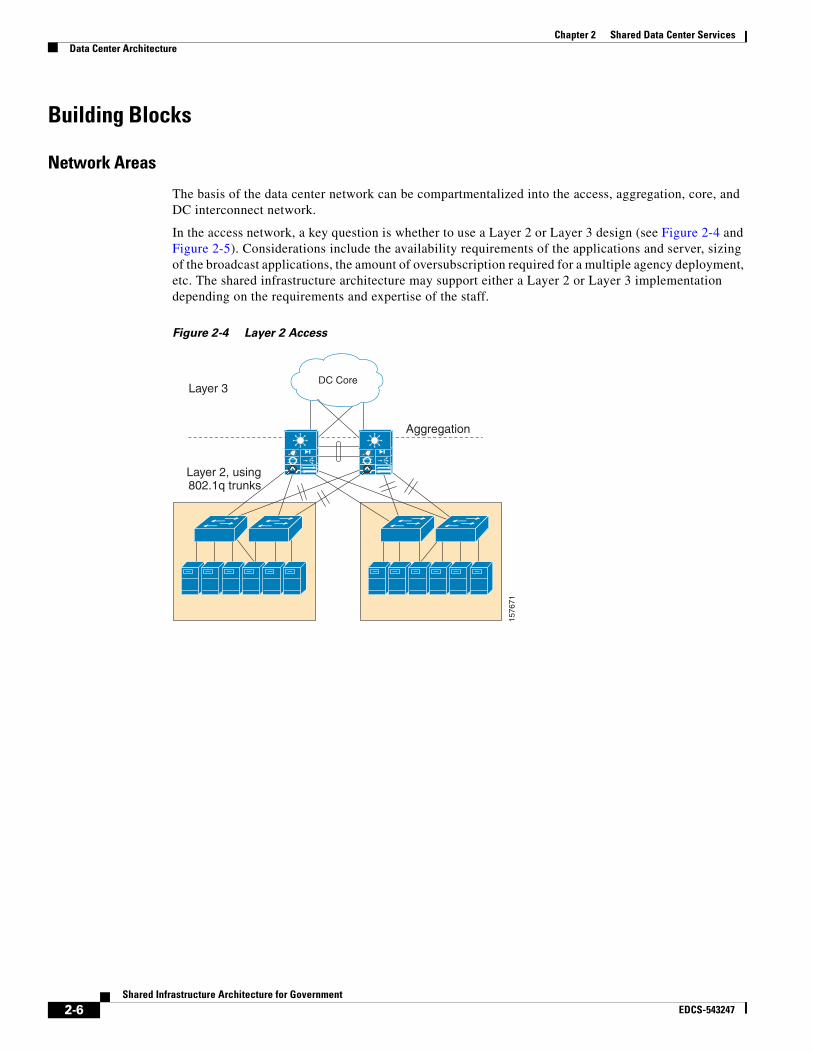
In the access network, a key question is whether to use a Layer 2 or Layer 3 design (see Figure 2-4 and Figure 2-5). Considerations include the availability requirements of the applications and server, sizing of the broadcast applications, the amount of oversubscription required for a multiple agency deployment, etc. The shared infrastructure architecture may support either a Layer 2 or Layer 3 implementation depending on the requirements and expertise of the staff.
Figure 2-4 Layer 2 Access
DC Core
1576
71
Layer 2, using802.1q trunks
Layer 3
Aggregation
2-6Shared Infrastructure Architecture for Government
EDCS-543247

Chapter 2 Shared Data Center ServicesData Center Architecture
Figure 2-5 Layer 3 Access
In the aggregation network, several key architectural components are positioned. The aggregation network must also meet scalability demands by aggregating traffic into the DC core. To provide security and advanced application intelligence to each agency utilizing the shared infrastructure, the aggregation layer has built-in security capabilities using distributed-denial-of-service (DDoS) blades, application intelligence with the ACE product, and additional Layer 4-7 services such as firewall, session load balancing, Secure Sockets Layer (SSL), and IDS. These powerful capabilities at the aggregation layer enable agencies without the expertise to design and operate these advanced services to still benefit from them through the shared data center approach.
In the DC core network, connectivity to the enterprise is provided to multiple sites and multiple agencies. The DC core is built to be very highly scalable with 10 Gigabit Ethernet links and redundancy that provides the capability to isolate failure domains and ensure connectivity between critical assets.
For widely dispersed agencies, such as country wide, that require connectivity, it is critical to ensure site survivability and geographic diversity of the data centers. To meet this demand, multiple data centers have various options to deliver on DC interconnect, ranging from a self-managed or service provider-managed WAN that can be supported over Metro Ethernet networks, traditional SONET/SDH networks, or dense wavelength-division multiplexing (DWDM) networks. These connectivity options maintain carrier-class attributes for communication between multiple data centers.
Network DNA
Meeting the traditionally expected requirements for data centers, such as scalability, availability, and reliability, is central to a shared data center network. Cisco products for data center architectures are designed to be highly reliable. Adding adherence to design principles for network availability ensures that shared data centers are always accessible.
In a Layer 2 network, Rapid Per-VLAN Spanning Tree (PVST+) or PVST+ is used on the switches to provide fast convergence of STP. For even faster convergence times, with zero seconds of packet loss, Layer 3 fast-convergence techniques with Open Shortest Path First (OPSF) protocol and Enhanced Interior Gateway Routing Protocol (EIGRP) can help ensure that applications, servers, and storage units are not affected in case of a failure.
1576
83L3 Access withmulticast sources
L3 Access withmulticast sources
DC Core
Layer 3
2-7Shared Infrastructure Architecture for Government
EDCS-543247

Chapter 2 Shared Data Center ServicesData Center Architecture
An important capability to protect data center servers is network interface card (NIC) teaming and clustering. Clustering exists when multiple servers for a specific agency are clustered together to behave as a single device—a common method for ensuring high availability and load balancing for servers. Two servers in a cluster may even be across different switches supported by extended VLANs and STP diameter. The servers communicate at Layer 2 to exchange state, session, and other information. With NIC teaming, it is common for servers to be dual connected for high availability. If a NIC loses connectivity, the other NIC inherits the properties of the failed NIC. Therefore the server is always reachable by the same IP address. To support this, both NICs must belong to the same broadcast domain and the access switches must provide Layer 2 adjacency between the two NICs.
Network Virtualization and Segmentation
As next-generation data centers are designed, virtualization and segmentation of network assets enables increased flexibility and cost savings to government agencies building shared infrastructures. Virtualization allows the vast numbers of servers and high storage volume to be centralized into redundant data centers, allowing devices to be centrally managed and maximally utilized. Segmentation takes the virtualization of the data center one step further, allowing the same infrastructure to be shared among multiple agencies. To support segmentation, the critical attribute is that the physical resource is virtually distinct and separate. For the government, this allows a converged network to deploy common and sustainable services to a building that supports multiple agencies which want to offload services to a shared network infrastructure serviced by the data centers. The common network infrastructure securely provides segmentation of traffic between the multiple agencies. Segmentation could also provide departmental isolation within a specific agency if that is a requirement. Common methods of isolation include:
• Guest access
• Closed user groups
• Application-access rights
• Departments and divisions such as finance, engineering, and administrative
This model provides greater flexibility for the placement of the equipment in the network, the packaging of the system, and the capacity it can support. The agencies incur lower CapEx for equipment and lower OpEx because of the resulting efficiencies and the capability to enable newer services, faster deployments, and simplification of network operations. Note that although the focus in this section is on the shared data center, segmentation and virtualization must also be designed across the end-to-end network.
2-8Shared Infrastructure Architecture for Government
EDCS-543247

Chapter 2 Shared Data Center ServicesData Center Architecture
Figure 2-6 Network Virtualization and Segmentation
To achieve the segmentation and virtualization requirements, some foundational steps must be implemented across the entire network, which require that branch and campus locations be designed with proper security, segmentation, and QoS. The WAN connection that connects these dispersed sites must also support VRFs to isolate traffic as illustrated in Figure 2-6. Inside the data center, access to storage and servers is preserved through the traffic separation. As we design the virtualization and segmentation, we must also pay attention to the fundamental elements of access control, path isolation, and the services edge.
Agricultural Department (500 employees)
Food and Safety(200 employees)
Farm Services(30 employees)
IP IP IP
IP IP IP
IP IP IP
WAN
WAN
DC Core
VRF-green
VRF-red
VRF-blue
VRF-yellow
Agricultural Department
Food and Safety Department
Farm Services Department
Shared
Common & SharedApplication Area
AggregationAggregation
1576
72
2-9Shared Infrastructure Architecture for Government
EDCS-543247

Chapter 2 Shared Data Center ServicesData Center Architecture
Figure 2-7 Access Control, Path Isolation, and Services Edge
Other issues to consider when designing a shared data center include:
• Components of the network infrastructure should all be VRF-aware. VRF is critical to enable the isolation of virtual traffic flows across a shared physical infrastructure.
• Determine if the service modules providing the services edge are able to support multiple and isolated user bases. Products such as the Cisco ACE blade support this scenario.
• Define each functional domain clearly and independently while establishing a clear handoff between each domain across the end-to-end network.
• Ensure that self-defending network principles are implemented throughout the network including the data center.
Table 2-1 Fundamental Elements of Virtualization and Segmentation
Role Function
Access control Authenticate client (user, device, application) attempting to gain network access
Authorize client into a partition (VLAN, ACL)
Deny access to unauthenticated clients
Path isolation Maintain traffic partitioned over Layer 3 infrastructure
Transport traffic over isolated Layer 3 partitions
Map Layer 3 isolated path to VLANs in access and services edge
Services edge Provide access to services described through the intelligence layer
Make decision on shared versus dedicated resource
Apply policy per partition
Isolate application environments if necessary15
7673
GRE
VRFs
MPLS
Access Control Path Isolation Services Edge
Branch - Campus WAN – MAN - Campus Data Center - Internet Edge -Campus
Agricultural DepartmentFood and Safety DepartmentFarm Services Department
2-10Shared Infrastructure Architecture for Government
EDCS-543247
Chapter 2 Shared Data Center ServicesData Center Architecture
Virtualized Data Center Benefit Example—Shared Infrastructure Backup and Recovery
To illustrate the efficiencies that can be gained through a virtualized data center, consider a critical operation that must be performed on the data located in storage servers, such as network backup. Figure 2-1 demonstrated the inefficiencies of dedicated data centers with dedicated storage components. In the Farm Services example, the data center was located in a decentralized site in City A. Hence each site, such as City B, may require their own data storage because of its inability to access a decentralized data center. The City B site, along with each individual site, has to have the necessary equipment and incurs the logistical overhead of maintaining the backup process. In addition, data retrieval becomes more complicated and time-consuming. Large efficiency gains become feasible when one considers multiple agencies each supporting, in possibly inconsistent ways, its own instance of this backup and recovery process.
Figure 2-2 illustrates a shared and virtualized data center architecture. Agencies can now depend on a center of excellence to securely operate this shared infrastructure. Consolidating the data center with its storage servers into centralized facilities with an IP-enabled SAN streamlines a consistent backup-and-retrieval process for each agency and requires fewer human and equipment resources. This scenario translates to lower cost through consolidated resources with more versatility to assess assets across agencies or multiple departments within an agency. A case study by the German operator izn shows the benefits achieved through this process. For more information, refer to:
• izn Data Storage Facility Critical to German Government Uses New Technology to Decrease Operational Costs: http://www.cisco.com/web/strategy/docs/gov/izn.pdf
• izn Data Storage Overview http://www.cisco.com/web/strategy/docs/gov/izn_customer_facing_preso.ppt
Virtualized Data Center Benefit Example—Continuity of Operations
Virtualization of the data center is an essential component of the shared infrastructure architecture to ensure continuity of operations. Many types of failures might prevent users from gaining access to critical data required to support a client. The cause of the failure may be fixed, but the failure to meet continuity of operations commitments is remembered by clients and can have long-lasting effects.
2-11Shared Infrastructure Architecture for Government
EDCS-543247

Chapter 2 Shared Data Center ServicesData Center Architecture
Figure 2-8 Scenario 2—Continuity of Operations
Assume the Farm Services’ data center is colocated with the City A facility. The data center is not virtualized, so there are potential single points of failure. If a server fails, a link fails, or there is a denial of service, users in City B are unable to access servers in City A. The City B agency is unable to support its operations until the problem is fixed, which could take hours.
In another scenario, assume that, because of some unknown failure, Agriculture Department users in City A and City B are unable to access data in the City C data center. A common best practice in the virtualization of the data center is data replication across primary and backup data centers. Data is not contained in a specific data center; rather the data is virtualized so that the City D data center can immediately come online to service the data request. In this scenario, disruptions to a specific data center do not result in any negative impact on continuity of operations.
Agricultural Department (500 employees)
Farm Services(30 employees)
Farm Services(10 employees)
IP IP IP
IP IP IPIP IP IP
Agricultural Department (100 employees)
City A City B
Wide Area Network
1576
74
Farm Services Data Center
Agricultural DepartmentData Center - City C
Agricultural DepartmentData Center - City D
IP IP IP
2-12Shared Infrastructure Architecture for Government
EDCS-543247
Chapter 2 Shared Data Center ServicesData Center Architecture
Network Intelligence
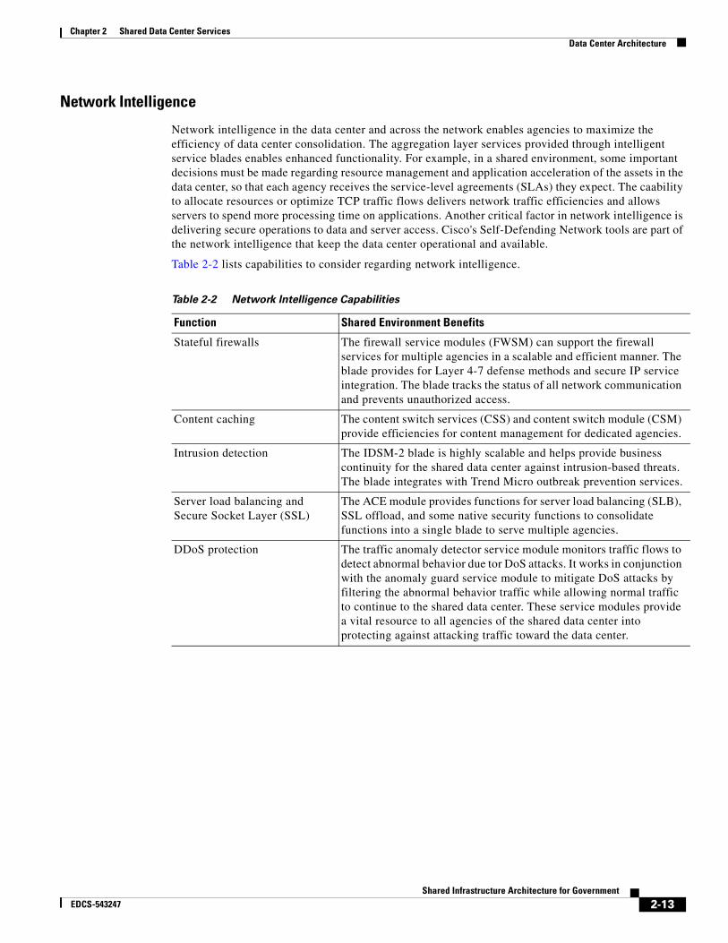
Network intelligence in the data center and across the network enables agencies to maximize the efficiency of data center consolidation. The aggregation layer services provided through intelligent service blades enables enhanced functionality. For example, in a shared environment, some important decisions must be made regarding resource management and application acceleration of the assets in the data center, so that each agency receives the service-level agreements (SLAs) they expect. The caability to allocate resources or optimize TCP traffic flows delivers network traffic efficiencies and allows servers to spend more processing time on applications. Another critical factor in network intelligence is delivering secure operations to data and server access. Cisco's Self-Defending Network tools are part of the network intelligence that keep the data center operational and available.
Table 2-2 lists capabilities to consider regarding network intelligence.
Table 2-2 Network Intelligence Capabilities
Function Shared Environment Benefits
Stateful firewalls The firewall service modules (FWSM) can support the firewall services for multiple agencies in a scalable and efficient manner. The blade provides for Layer 4-7 defense methods and secure IP service integration. The blade tracks the status of all network communication and prevents unauthorized access.
Content caching The content switch services (CSS) and content switch module (CSM) provide efficiencies for content management for dedicated agencies.
Intrusion detection The IDSM-2 blade is highly scalable and helps provide business continuity for the shared data center against intrusion-based threats. The blade integrates with Trend Micro outbreak prevention services.
Server load balancing and Secure Socket Layer (SSL)
The ACE module provides functions for server load balancing (SLB), SSL offload, and some native security functions to consolidate functions into a single blade to serve multiple agencies.
DDoS protection The traffic anomaly detector service module monitors traffic flows to detect abnormal behavior due tor DoS attacks. It works in conjunction with the anomaly guard service module to mitigate DoS attacks by filtering the abnormal behavior traffic while allowing normal traffic to continue to the shared data center. These service modules provide a vital resource to all agencies of the shared data center into protecting against attacking traffic toward the data center.
2-13Shared Infrastructure Architecture for Government
EDCS-543247
Chapter 2 Shared Data Center ServicesData Center Architecture
Network Intelligence Benefit Example—Site Expansion
A critical requirement that network intelligence meets is the capability to support the business needs of agencies. As the agencies evolve, many changes may occur:
• An agency may be realigned to support a new function.
• Two or more agencies may merge and therefore consolidate their data center facilities.
• An agency may expand into new territories to support its constituents.
An intelligent infrastructure helps ensure that these transitions are achieved in a timely manner.
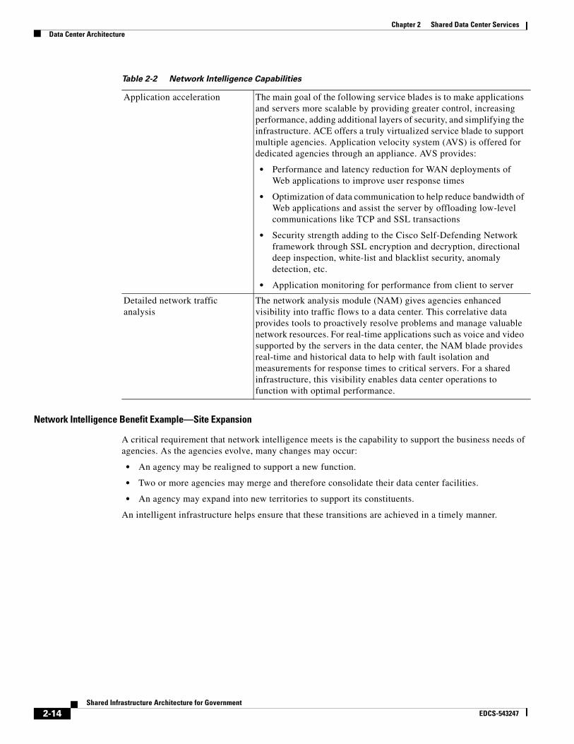
Application acceleration The main goal of the following service blades is to make applications and servers more scalable by providing greater control, increasing performance, adding additional layers of security, and simplifying the infrastructure. ACE offers a truly virtualized service blade to support multiple agencies. Application velocity system (AVS) is offered for dedicated agencies through an appliance. AVS provides:
• Performance and latency reduction for WAN deployments of Web applications to improve user response times
• Optimization of data communication to help reduce bandwidth of Web applications and assist the server by offloading low-level communications like TCP and SSL transactions
• Security strength adding to the Cisco Self-Defending Network framework through SSL encryption and decryption, directional deep inspection, white-list and blacklist security, anomaly detection, etc.
• Application monitoring for performance from client to server
Detailed network traffic analysis
The network analysis module (NAM) gives agencies enhanced visibility into traffic flows to a data center. This correlative data provides tools to proactively resolve problems and manage valuable network resources. For real-time applications such as voice and video supported by the servers in the data center, the NAM blade provides real-time and historical data to help with fault isolation and measurements for response times to critical servers. For a shared infrastructure, this visibility enables data center operations to function with optimal performance.
Table 2-2 Network Intelligence Capabilities
2-14Shared Infrastructure Architecture for Government
EDCS-543247
Chapter 2 Shared Data Center ServicesData Center Architecture
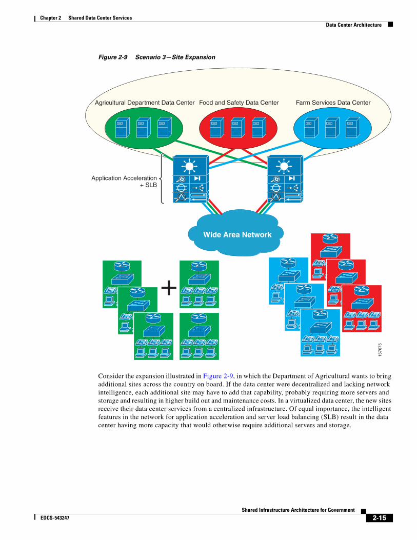
Figure 2-9 Scenario 3—Site Expansion
Consider the expansion illustrated in Figure 2-9, in which the Department of Agricultural wants to bring additional sites across the country on board. If the data center were decentralized and lacking network intelligence, each additional site may have to add that capability, probably requiring more servers and storage and resulting in higher build out and maintenance costs. In a virtualized data center, the new sites receive their data center services from a centralized infrastructure. Of equal importance, the intelligent features in the network for application acceleration and server load balancing (SLB) result in the data center having more capacity that would otherwise require additional servers and storage.
IP IP IP
IP IP IP
IP IP IP
IP IP IP
IP IP IP
IP IP IP
IP IP IP
IP IP IP
IP IP IP
IP IP IP
IP IP IP
Agricultural Department Data Center
Application Acceleration+ SLB
Food and Safety Data Center Farm Services Data Center
Wide Area Network
+
1576
75
2-15Shared Infrastructure Architecture for Government
EDCS-543247

Chapter 2 Shared Data Center ServicesData Center Architecture
Network Security
Security threats must be taken very seriously when network assets are concentrated in a data center. From an attacker perspective, the data center is an attractive target since the damage has a broad impact. However layers of defense in the data center and across the end-to-end network can detect attacks, rapidly report them, and mitigate them without any impact to operations. The Cisco Self-Defending Network provides the necessary protective technologies across the end-to-end network.
Security components that provide layers of defense to enable the mandatory protection for a shared data center include:
• Inherent network security features built into products at both the hardware and software level that help ensure component reliability when under attack. For example, Cisco NetFlow is built into many Cisco products and provides detailed data about network traffic flows that can be used for statistical profiling, even for day-zero attacks.
• Cisco IOS® features that can be used to design and build secure networks. Cisco has published many recommendations about best security practices when deploying networks. A general approach should factor in methods to:
– Secure the router and router services
– Secure the control plane
– Secure the data plane
– Define a logical methodology to handle and mitigate known threat types
For a paper on infrastructure protection on Cisco IOS platforms, which provides an overview of security techniques for Cisco routers and switches, see:
http://www.cisco.com/application/pdf/en/us/guest/products/ps1838/c1244/cdccont_0900aecd804ac831.pdf
• Cisco Security Monitoring, Analysis, and Response System appliances combine network intelligence, context correlation, vector analysis, anomaly detection, hotspot identification, and automated mitigation capabilities allowing managers to accurately identify, manage, and eliminate network attacks and maintain compliance with policies. Cisco’s Security Monitoring, Analysis, and Response System helps track a broad array of security measures by monitoring operations and managing security information. The appliance centrally aggregates logs and events from a variety of devices, including routers and switches, security devices and applications, hosts, and network traffic. It captures thousands of events, efficiently classifies incidents using data reduction techniques, and compresses the information for archiving. A key source of data is the NetFlow information from routers and switches in the network.
• Access control can be provided through:
– Cisco Security Agent to check the operation of the application against the application’s security policy, making a real-time allow-deny decision on its continuation and determining if logging the request is appropriate.
– Cisco Network Admission Control (NAC) to ensure every device connected to a Cisco port adheres to the established policies before it is allowed to connect to the network using 802.1x, Cisco Secure Access Control System, and Cisco Clean Access.
• The aggregation layer provides an intelligent layer of defense that can be hosted by the service blades on the Cisco Catalyst® 6500 switch in the data center. These service blades can enable firewall, IDS, URL filtering, and DDoS protection services to the agencies supported by the data center. This capability provides virtualization and segmentation of services to the agencies.
2-16Shared Infrastructure Architecture for Government
EDCS-543247
Chapter 2 Shared Data Center ServicesData Center Architecture
• Isolation of traffic specific to an agency is an important tool to compartmentalize any agency-specific security threats to only that agency. Traffic separation ensures that other agencies of a shared infrastructure are unaffected. The tools of the targeted agency deployed by the shared infrastructure provide the necessary mitigation schemes to handle the localized threat.
Network Security Benefit Example—Protection from Data Center Attacks
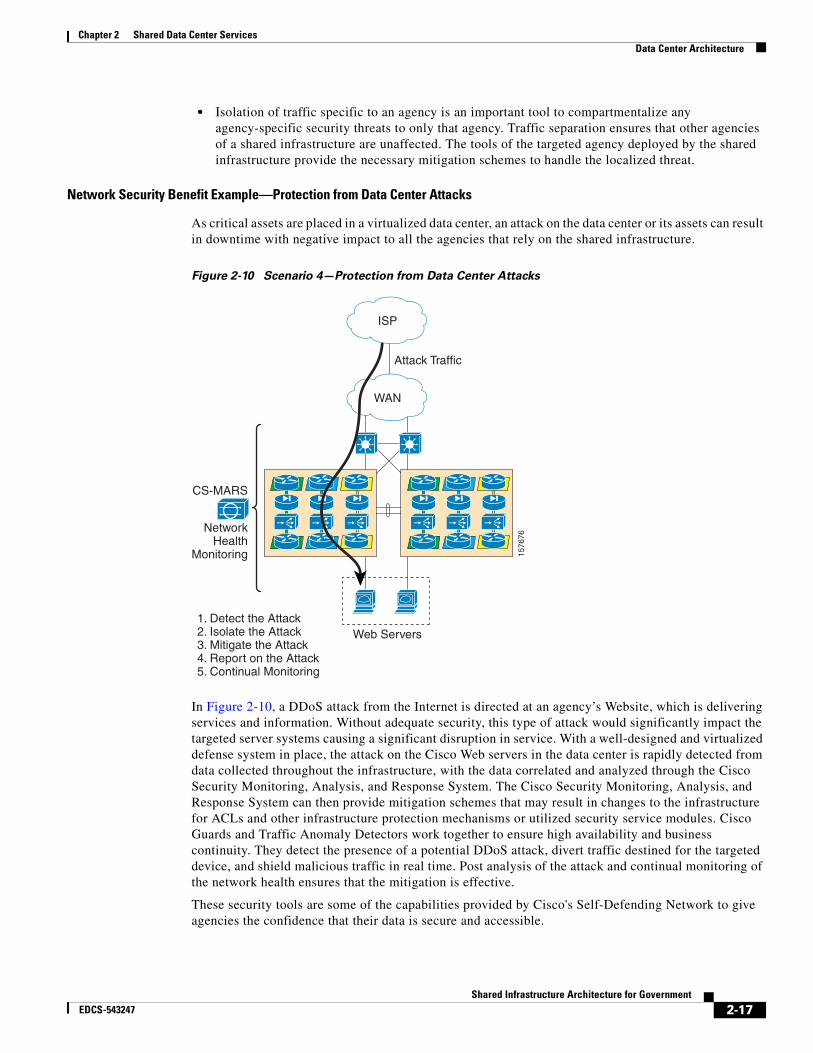
As critical assets are placed in a virtualized data center, an attack on the data center or its assets can result in downtime with negative impact to all the agencies that rely on the shared infrastructure.
Figure 2-10 Scenario 4—Protection from Data Center Attacks
In Figure 2-10, a DDoS attack from the Internet is directed at an agency’s Website, which is delivering services and information. Without adequate security, this type of attack would significantly impact the targeted server systems causing a significant disruption in service. With a well-designed and virtualized defense system in place, the attack on the Cisco Web servers in the data center is rapidly detected from data collected throughout the infrastructure, with the data correlated and analyzed through the Cisco Security Monitoring, Analysis, and Response System. The Cisco Security Monitoring, Analysis, and Response System can then provide mitigation schemes that may result in changes to the infrastructure for ACLs and other infrastructure protection mechanisms or utilized security service modules. Cisco Guards and Traffic Anomaly Detectors work together to ensure high availability and business continuity. They detect the presence of a potential DDoS attack, divert traffic destined for the targeted device, and shield malicious traffic in real time. Post analysis of the attack and continual monitoring of the network health ensures that the mitigation is effective.
These security tools are some of the capabilities provided by Cisco's Self-Defending Network to give agencies the confidence that their data is secure and accessible.
WAN
Attack Traffic
Web Servers1. Detect the Attack2. Isolate the Attack3. Mitigate the Attack4. Report on the Attack5. Continual Monitoring
NetworkHealth
Monitoring
CS-MARS
1576
76
ISP
2-17Shared Infrastructure Architecture for Government
EDCS-543247

Chapter 2 Shared Data Center ServicesSummary
Server FabricThe server fabric provides the performance and control necessary to access the applications and servers in a shared data center. From a shared infrastructure perspective, the server fabric virtualizes physical components such as I/O and CPU and provides policy-based dynamic resource allocation to the assets.
For management of the policies used by the server switch, VFrame director or third-party software provides the rules. Based on the rules assembled, the virtual server then acts upon policies such as:
• Selecting server(s) that meet minimum criteria (e.g., CPU, memory)
• Booting server(s) over the network with appropriate application or operating software image
• Creating virtual IPs in servers and maps to VLANs for client access
• Creating virtual host bus adapters (HBAs) in servers and maps to zones, logical unit numbers (LUNs), and worldwide node names (WWNNs) for storage access
The blade servers that operate on the server fabric greatly benefit server consolidation. Servers that may be dispersed across multiple locations and at hard-to-manage locations can now be centrally placed in the blade servers. A well-designed shared data center architecture is critical to server consolidation, which translates to reduced management, reduced infrastructure for space and power, and maximum utilization of the active servers.
For more details about Cisco’s server networking and virtualization, see: http://www.cisco.com/en/US/products/ps6418/index.html.
SAN FabricThe SAN fabric handles the connectivity in the data center from the network to the storage farms. Many of these networks were designed around an inefficient full mesh network, yielding poor effectiveness on port count and thereby driving up the total cost. A more structured design using a traditional core/edge design or collapsed core design that combines the core and edge layers helps reduce the complexities and drive more effective use of the ports.
From a shared infrastructure perspective, the use of a VSAN provides a mechanism to allocate ports within a physical fabric to create virtual fabrics. Conceptually, the VSAN model is analogous to VLANs in an Ethernet. The virtual segments are isolated to provide secure access to the storage data. To enhance the isolation, events that are generated in the fabric are segmented per VSAN, so statistics can be gathered on individual VSANs, which can help identify failure scenarios. With hardware-based capabilities, membership in the VSAN can be explicitly tagged on interswitch links. The cost of a physical redundant fabric can drive up costs. By providing virtual allocation to these resources, wasted ports are reduced.
For more details about Cisco’s storage networking, see: http://www.cisco.com/en/US/products/hw/ps4159/index.html.
SummaryData center consolidation yields many benefits for governments that want to build a shared infrastructure environment. As agencies realign for various business reasons or geographically expand to handle more capacity, the data center plays a critical role in helping them meet their business requirements. The advantages of a shared infrastructure are even more apparent in the data center. Cost savings realized through the physical reductions achieved by server and storage consolidation translate directly into space and power savings. These consolidations also reduce distributed resources and hence diminish the
2-18Shared Infrastructure Architecture for Government
EDCS-543247

Chapter 2 Shared Data Center ServicesSummary
complexity of managing isolated storage and server farms, allowing agencies to better allocate resources to serve their constituents. Another huge benefit is having updated technology to protect data centers, provide greater network intelligence to deliver the data, and rapidly enable new services. Business continuance is preserved through security and high availability. These factors will forever change how data centers are designed and operated.
2-19Shared Infrastructure Architecture for Government
EDCS-543247

Chapter 2 Shared Data Center ServicesSummary
2-20Shared Infrastructure Architecture for Government
EDCS-543247

Shared InfrEDCS-543247
C H A P T E R 3
Shared Security ServicesIntroductionSecurity is a process, not a product. Security should be built into the overall architecture from the beginning. After you determine the appropriate security measures required to secure assets, you should continuously monitor and re-evaluate to ensure that new threats are addressed. Figure 3-1, the Security Wheel, illustrates this continuous process based on a foundational security policy and incremental improvement.
Figure 3-1 Security Is Process, Not Products
Managing security risk and compliance audit requirements requires a system-based best-practice approach to controls. The network itself plays a fundamentally important role in achieving these objectives because it touches every aspect of the IT infrastructure. The point-product architectural model has become inadequate for managing today’s network security risk, compliance, and audit requirements. An end-to-end, systems-based approach aligned with industry frameworks and best practices is required. It should be integrated, collaborative, and adaptive—an approach that helps administrators better manage network security risk while enabling auditors to satisfy internal and external compliance
AgencySecurityPolicy
SECURE
TEST
MONITORandRESPOND
MANAGEand
IMPROVE
1576
62
3-1astructure Architecture for Government

Chapter 3 Shared Security ServicesShared Infrastructure Security Risks
requirements. The Cisco Self-Defending Network provides an approach, managing network security risk and supporting industry control frameworks such as Control Objectives for Information and related Technology (COBIT) and 1SO 17799 best practices. This approach helps an organization better manage its network security risk while readying it to meet regulatory compliance.
Figure 3-2 Threat Capabilities—More Dangerous and Easier to Use
Shared Infrastructure Security RisksThe vast majority of today’s government agencies are increasingly dependent on automated business processes. Information systems and the networks that support them are now viewed as strategic assets based on their ability to contribute to the overall strategy and objectives of the business, the level of investment and resources committed, and new security risks that must be managed.
As a result, network and security administrators must find new ways to protect networks—and the data and applications they carry—from attacks that are faster, more complex, and more dangerous than ever before. But the historical point-product approach makes it difficult to acquire, deploy, and operationalize the security controls necessary to protect the enterprise infrastructure. As a result, trade-offs must often be made and organizations are forced to tolerate unacceptable levels of risk.
All organizations now face growing compliance demands, as regulations and public insistence require that appropriate steps be taken to ensure the proper use and protection of government, corporate, and personal information. For example, within the United States, a growing body of legislation includes:
• The U.S. Public Company Accounting Reform and Investor Protection Act of 2002 (Sarbanes-Oxley Act)
• The Gramm-Leach-Bliley Financial Services Modernization Act (GLBA) of 1999
• The U.S. Healthcare Insurance Portability and Accountability Act (HIPAA) of 1996
• The European safe harbor regulations
Password Guessing
Self Replicating Code
Password Cracking
Exploiting Known Vulnerabilities
Disabling Audits
BackDoors
Hijacking Sessions
SweepersSniffers
Packet Forging/Spoofing
NewInternetWorms
Sophisticationof HackerTools
High
Low
1980 1990 2000
TechnicalKnowledgeRequired
Stealth Diagnostics DDOS
1576
63
3-2Shared Infrastructure Architecture for Government
EDCS-543247

Chapter 3 Shared Security ServicesNetwork Security in a Secure Segment
• California Senate Bill 1386 (SB1386) of 2003 and the Children’s Online Privacy Protection Act (COPPA) of 1998
Historically, the approach to managing network security risk and compliance audit requirements has been fragmented across organizational divisions and departments, resulting in a duplication of effort and technology. Inevitably these different approaches are inconsistent and control systems overlap, contradict, or undermine one another. Measurement and reporting are equally fragmented, resulting in administrators not knowing whether they are efficiently and effectively managing network risk, including emerging compliance requirements.1 Not surprisingly, according to Forrester Research, businesses now seek a formalized, consistent approach to managing information risk and compliance requirements across the entire organization.2
In a shared service and/or network infrastructure environment, security does not have to be minimized to offer such services. Each tenant on the network, whether a department, subagency, customer, or guest, has specific security requirements that can likely be met in a shared environment.
The scenarios outlined in this paper use the Agriculture Department to illustrate and explain the operations of a shared network infrastructure and service.
To enhance the overall network security, the service provider, the Agriculture Department in this case, could offer a service to the tenants that updates the virus protection software on the computers prior to allowing access to the network. By sharing a network infrastructure and services with other departments and agencies, the Agriculture Department could improve the security of the information while providing timely access and improved collaboration. In fact, this is exactly what the U.S. Office of Management and Budget is proposing by establishing a specific line of business for IT security.
This is a brief overview of the current security environment. By leveraging common shared services, it allows a more comprehensive security plan to be implemented and maintained by the line of business best equipped to manage it. Many of the same policies and requirements can be implemented on a customer-by-customer basis, which gives individual customers the autonomy to implement additional security measures if required.
Network Security in a Secure SegmentIn a shared infrastructure, you do not have to sacrifice control of your security policies and requirements. From the provider’s view, once your traffic is segmented, you have a secured network since your traffic is being transported virtually separate from other network traffic. If you want to increase security, consider that the implementation of some security techniques may prevent the implementation of other traffic management techniques discussed in this chapter. If additional security is required, the network provider should be consulted, as it may affect how your network is designed and implemented. It may also affect what shared services are available.
For example, if the Agriculture Department is providing a network, it may create a VPN or provision a circuit-based link through its network for a subagency. In doing so, it secured the subagency’s traffic from everyone else’s traffic. However, the subagency can implement IPSec to further encrypt network traffic. This allows every subagency packet transiting the Agriculture Department’s network to be encrypted to the sub-agency’s standards.
Routers can combine security and network functions in a single device, independently delivering VPN, stateful firewall, intrusion protection, and URL filtering in addition to full-featured IP routing. Depending on budget constraints, traffic load, security requirements, and service load, this may or may
1. “The Tao of Compliance: Unifying Controls over Chaos,” by Cass Brewer; IT Compliance Institute’s ComplianceNOW http://www.itcinstitute.com/display.aspx?id=465
2. Forrester, Trends 2005: Risk and Compliance Management, October 25, 2004
3-3Shared Infrastructure Architecture for Government
EDCS-543247
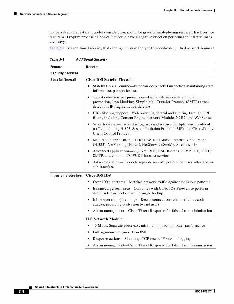
Chapter 3 Shared Security ServicesNetwork Security in a Secure Segment
not be a desirable feature. Careful consideration should be given when deploying services. Each service feature will require processing power that could have a negative effect on performance if traffic loads are heavy.
Table 3-1 lists additional security that each agency may apply to their dedicated virtual network segment.
Table 3-1 Additional Security
Feature Benefit
Security Services
Stateful firewall Cisco IOS Stateful Firewall
• Stateful firewall engine—Performs deep packet inspection maintaining state information per application
• Threat detection and prevention—Denial-of-service detection and prevention, Java blocking, Simple Mail Transfer Protocol (SMTP) attack detection, IP fragmentation defense
• URL filtering support—Web browsing control and auditing through URL filters, including Content Engine Network Module, N2H2, and WebSense
• Voice traversal—Firewall recognizes and secures multiple voice protocol traffic, including H.323, Session Initiation Protocol (SIP), and Cisco Skinny Client Control Protocol
• Multimedia application—VDO Live, RealAudio, Internet Video Phone (H.323), NetMeeting (H.323), NetShow, CuSeeMe, Streamworks
• Advanced applications—SQLNet, RPC, BSD R-cmds, ICMP, FTP, TFTP, SMTP, and common TCP/UDP Internet services
• AAA integration—Supports separate security policies per user, interface, or sub-interface
Intrusion protection Cisco IOS IDS
• Over 100 signatures—Matches network traffic against malicious patterns
• Enhanced performance—Combines with Cisco IOS Firewall to perform deep packet inspection with a single lookup
• Inline operation (shunning)—Resets connections with malicious code attacks, providing protection to end users
• Alarm management—Cisco Threat Response for false alarm minimization
IDS Network Module
• 45 Mbps. Separate processor, minimum impact on router performance
• Full signature set (more than 850)
• Response actions—Shunning, TCP resets, IP session logging
• Alarm management—Cisco Threat Response for false alarm minimization
3-4Shared Infrastructure Architecture for Government
EDCS-543247
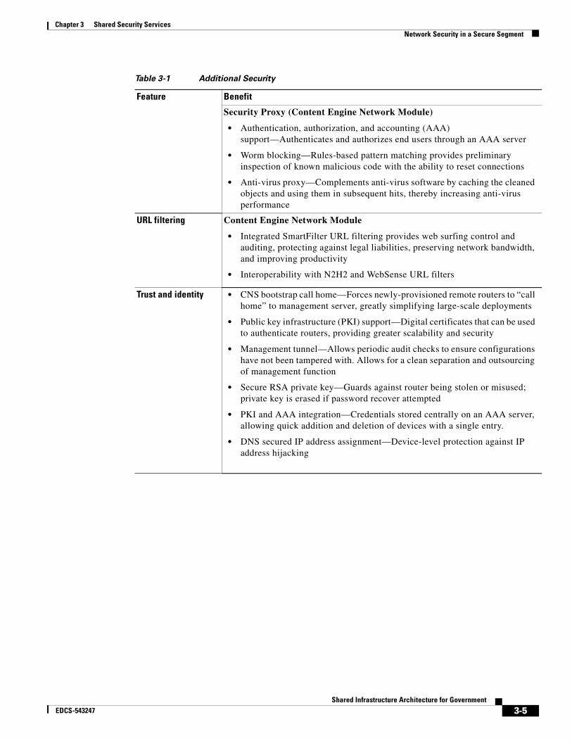
Chapter 3 Shared Security ServicesNetwork Security in a Secure Segment
Security Proxy (Content Engine Network Module)
• Authentication, authorization, and accounting (AAA) support—Authenticates and authorizes end users through an AAA server
• Worm blocking—Rules-based pattern matching provides preliminary inspection of known malicious code with the ability to reset connections
• Anti-virus proxy—Complements anti-virus software by caching the cleaned objects and using them in subsequent hits, thereby increasing anti-virus performance
URL filtering Content Engine Network Module
• Integrated SmartFilter URL filtering provides web surfing control and auditing, protecting against legal liabilities, preserving network bandwidth, and improving productivity
• Interoperability with N2H2 and WebSense URL filters
Trust and identity • CNS bootstrap call home—Forces newly-provisioned remote routers to “call home” to management server, greatly simplifying large-scale deployments
• Public key infrastructure (PKI) support—Digital certificates that can be used to authenticate routers, providing greater scalability and security
• Management tunnel—Allows periodic audit checks to ensure configurations have not been tampered with. Allows for a clean separation and outsourcing of management function
• Secure RSA private key—Guards against router being stolen or misused; private key is erased if password recover attempted
• PKI and AAA integration—Credentials stored centrally on an AAA server, allowing quick addition and deletion of devices with a single entry.
• DNS secured IP address assignment—Device-level protection against IP address hijacking
Table 3-1 Additional Security
Feature Benefit
3-5Shared Infrastructure Architecture for Government
EDCS-543247
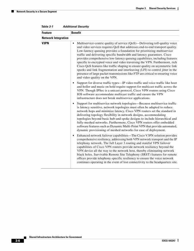
Chapter 3 Shared Security ServicesNetwork Security in a Secure Segment
Network Integration
V3PN • Multiservice-centric quality of service (QoS)—Delivering toll-quality voice and video services requires QoS that addresses end-to-end transport quality. Low-latency queuing provides a foundation for prioritizing multiservice traffic and delivering specific bandwidth and latency guarantees. Cisco provides comprehensive low-latency queuing capabilities, including features specific to encrypted voice and video traversing the VPN. Furthermore, rich Cisco QoS features like traffic shaping to ensure quality on asymmetric link speeks and link fragmentation and interleaving (LFI) to control jitter in the presence of large packet transmissions like FTP are critical to ensuring voice and video quality on the VPN.
• Support for diverse traffic types—IP video traffic and voice traffic like hoot and holler and music on hold require support for multicast traffic across the VPN. Though IPSec is a unicast protocol, Cisco VPN routers using Cisco IOS software accommodate multicast traffic and ensure the VPN infrastructure does not break multiservice applications.
• Support for multiservice network topologies—Because multiservice traffic is latency sensitive, network topologies must often be adapted to reduce network hops and minimize latency. Cisco VPN routers set the standard in delivering topology flexibility in network designs, accommodating topologies beyond basic hub-and-spoke designs to include hierarchical and fully-meshed networks. Furthermore, Cisco VPN routers offer embedded software features such as Dynamic Multi-Point VPN that provide automated, dynamic provisioning of meshed networks for ease of deployment.
• Enhanced network failover capabilities—The Cisco V3PN solution provides comprehensive resiliency, addressing both VPN network transport and the IP telephony network. The full Layer 3 routing and stateful VPN failover capabilities of Cisco VPN routers provide network resiliency beyond the VPN device all the way to the network host, thereby eliminating network black holes. Survivable Remote Site Telephony (SRST) features for remote offices provide telephony-specific resiliency to ensure the voice network continues operating in the event of lost connectivity to the headquarters site.
Table 3-1 Additional Security
Feature Benefit
3-6Shared Infrastructure Architecture for Government
EDCS-543247

Chapter 3 Shared Security ServicesNetwork Security in a Secure Segment
Dynamic multipoint VPN (DMVPN)
• Virtual full mesh—Allows IPSec with routing protocols to be dynamically configured
• On-demand spoke-to-spoke tunnels—This industry-leading capability optimizes performance and reduces latency for real-time traffic
• Dynamic discovery of spoke-to-hub tunnels—Minimizes hub configuration and ongoing updates when new spokes are added
• QoS, multicast support—Required for latency-sensitive applications such as voice and video
• Tiered DMVPN—Allows preferential treatment of users and simplifies configuration
• Enhanced scalability—Load balancing doubles the performance compared to passive failover. Single hop to go from spoke to spoke reduces overhead on the system; tiered DMVPN extends scalability.
IPSec-to-MPLS integration
• VRF-aware IPSec—Terminates multiple customer edge IPSec tunnels onto a single provider edge VRF interface, reducing CapEx
IPSec NAT transparency
• Allows encrypted IPSec traffic to traverse Network Address Translation (NAT) or Port Address Translation (PAT) devices by wrapping IPSec within User Datagram Protocol (UDP), simplifying VPN design and deployment
High availability • IPSec stateful failover—Provides subsecond failover that provides reliability for mission critical application such as Systems Network Architecture (SNA), voice, and databases. Scales to thousands of remotes. Fewer help desk calls from end users in the event of a head-end failure.
• DMVPN load balancing and self-healing—Doubles the performances compared to passive failover while providing resiliency. Reroutes around link failures and maximizes up time.
• Easy VPN failover—Ability to failover to multiple backup peers successively
Table 3-1 Additional Security
Feature Benefit
3-7Shared Infrastructure Architecture for Government
EDCS-543247

Chapter 3 Shared Security ServicesNetwork Security in a Secure Segment
Management
IP Solutions Center (ISC)
• Policy-based management; scales from 50 to 20,000 devices
• Multiple VPN deployments—Site-to-site VPN, remote access VPN, DMVPN, Easy VPN
• PKI-based end-to-end authentication and audit checks
• Device abstraction layer—Allows policy rules to be created independent of devices and later pushed to different device implementations, such as PIX® and Cisco IOS firewall
• Bootstrap call home—Forces newly-provisioned routers to call home to management server, get authenticated, and receive their digital certificates and policies
• Hub-and-spoke, full and partial mesh topologies
• Design and deploy complex firewall rules
• Cisco IOS IDS provisioning and tuning
• Integrated routing—Open Shortest Path First (OSPF), Enhance Interior Gateway Routing Protocol (EIGRP), and Routing Information Protocol (RIP)
• Automate provisioning of failover and load balancing
• QoS provisioning
• Massive NAT configuration deployment
• Service provisioning—Network-based IPSec, MPLS, managed firewall, and managed IDS
CiscoWorks VPN/Security Management System (VMS)
• Policy-based management—For small to large enterprises (up to 700 devices)
• Combines Web-based tools for configuring, monitoring, and troubleshooting enterprise VPNs, firewalls, and network- and host-based IDS
• Device hierarchy and policy inheritance
• Industry-leading auto update feature—Allows a large number of firewalls to pull security configurations and update themselves easily and quickly
• Centralized role-based access control enables different groups to have different access rights across different devicees and applications
• Integrated monitoring of Cisco PIX® and Cisco IOS syslogs and events from network- and host-based IDS, along with event correlation
Table 3-1 Additional Security
Feature Benefit
3-8Shared Infrastructure Architecture for Government
EDCS-543247
Shared InfrEDCS-543247
C H A P T E R 4
Shared Infrastructure Network ManagementIntroductionNetwork management is an important component of overall network reliability and includes several categories:
• Configuration management—Process by which device configurations are standardized and centrally administered.
• Security management—Process by which the security policies are implemented, tested, and re-evaluated to ensure the overall network is secure based on agency policy. Policy management is also enforced within the security management framework.
• Event management—Process by which individual network elements send status updates (traps) to a management system that then can correlate the alarms and take action based on the policy set for a single event or series of events. Actions such as blinking lights, sounding alarms, sending pages, re-routing traffic, collecting network data, etc. can all be triggered based on how reactive or proactive network management functions are performed.
• Address management—Process to manage the IP address space. Policies should be set forth to properly categorize IP address space by whatever means administration deems effective, such as ensuring subnet masks are correct on the WAN link to ensure there are no wasted addresses or placing various departments in their own subnetworks.
• Application management—Process to ensure the IT department knows what software is resides on the network devices. This helps give technical support a standard frame of reference with regard to release numbers and patch applications.
• Asset management—Process to account for the network assets. There are a variety of means to collect information depending on network element capability.
Each of these processes fosters management of the infrastructure. Proactive management facilitates other processes such as trending, budgeting, support, and configuration. Each one plays a specific role and may interrelate to other management processes to achieve higher reliability and customer satisfaction.
Network management is an art based on science. It relies on individual network characteristics that make up network performance, error, efficiency, and trending analysis. Turning this data into actionable information for managing an agency requires proper monitoring and reporting of data relevant to a specific network. For example, an error report may reveal that network errors occurred during specific times of the day and hence may be related to specific events.
This chapter describes an option for a robust management infrastructure based on time-proven techniques and operations.
4-1astructure Architecture for Government
Chapter 4 Shared Infrastructure Network ManagementDemarcation Point
Demarcation PointThis is the physical point where the service provider hands off control/responsibility of the network to the customer. In many cases, customers can chose the demarcation point, allowing them to control as much or as little as they wish. The provider takes measures to ensure that customer changes to equipment cannot affect the operation of the provider’s network. The customer should also ensure that appropriate measures are taken to prevent provider changes from having unexpected adverse effects on the customer’s network operations and administration.
AdministrationThe provider may or may not allow various levels of administration to the network service equipment based on purchased service capability. In some cases, partial administration may be allowed for customer services. Cisco also offers multilevel administration access, enabling users who have full access to configure different levels of administration access for other administrators and user groups. In addition, CiscoWorks LAN Management Solution provides management domains for devices, simplifying configuration, administration, monitoring, and troubleshooting.
Service-Level AgreementsA service-level agreement (SLA) is a contract between a service provider and a customer that defines the terms of responsibility of the provider and consequences if those responsibilities are not met. A service provider is anyone who charges for and provides network or communications services.
Why Are SLAs Important?SLAs define the attributes for the portions of a network that are not controlled by the customer. This allows the customer to establish expectations for the network such as:
• Availability
• Delay
• Throughput
• Costs
• Reliability
Each of these attributes plays a critical role. Providers must engineer their networks to meet SLAs, so as not to incur penalties for network outages or performance issues. It is essential that the customer understand all the parameters of the SLA to minimize unexpected problems. For example, it is important to understand if network services can be preempted or denied and under what criteria this can occur.
ComplianceCustomers must monitor their networks over time to determine whether SLAs are being met. Many performance tools are available for this purpose. Customers must also be aware of where these measurements are taken. It is imperative that performance measurements be taken end-to-end utilizing several performance parameters. Applications today use many protocols and each should be tested and
4-2Shared Infrastructure Architecture for Government
EDCS-543247
Chapter 4 Shared Infrastructure Network ManagementNetwork Management Architecture
monitored if it is deemed critical to business operations, particularly since not all protocols perform identically across the network or in each segment of the network. Once these parameters are established, the network can be engineered to meet applications’ performance requirements. Note that customers should have a clear understanding of the process to follow when SLAs are not met, as well as the remediation of the noncompliance infraction.
Network Management ArchitectureNetwork management is typically implemented in one of two ways:
• In-band using the data path, as in enterprise/commercial networks
• Out-of-band using a separate network management infrastructure, often found in service provider networks
While in-band network management using Simple Network Management Protocol (SNMP) is very effective for commercial networks, it poses potential security risks in that access passwords are sent in the clear. SNMPv3 attempts to address this vulnerability, however DES or Message Digest Algorithm 5 (MD5) hash does not meet the stringent security requirements of governments.
To meet the security requirements inherent in classified networks, and the security requirements intrinsic to the devices themselves, a dedicated management network, typically referred to as a data communications network (DCN), might be considered for the provider. This can be accomplished by a physically separate link or a VPN tunnel.
A DCN has the ability to provide various levels of security, including physical separation of data and encryption, depending on the sensitivity and location of critical network elements.
What Is a DCN?A DCN is the out-of-band management network that customers’ IT organizations use to provide operations connectivity between the element management systems (EMSs) and network management systems/operations support systems (NMSs/OSSs) systems within a network operations center (NOC) and the respective network elements that they manage. These systems support OAM&P (Operations, Administration, Maintenance, and Provisioning) functions, including network surveillance, provisioning, service restoration, key management, etc. Network elements comprising the provisioned services infrastructure include SDH/SONET add-drop multiplexers (ADMs) and optical repeaters, xWDM optical equipment, voice switches, digital cross-connect systems, Frame Relay or ATM switches, routers, DSL access multiplexers (DSLAMs), digital loop transmission systems, etc.
4-3Shared Infrastructure Architecture for Government
EDCS-543247
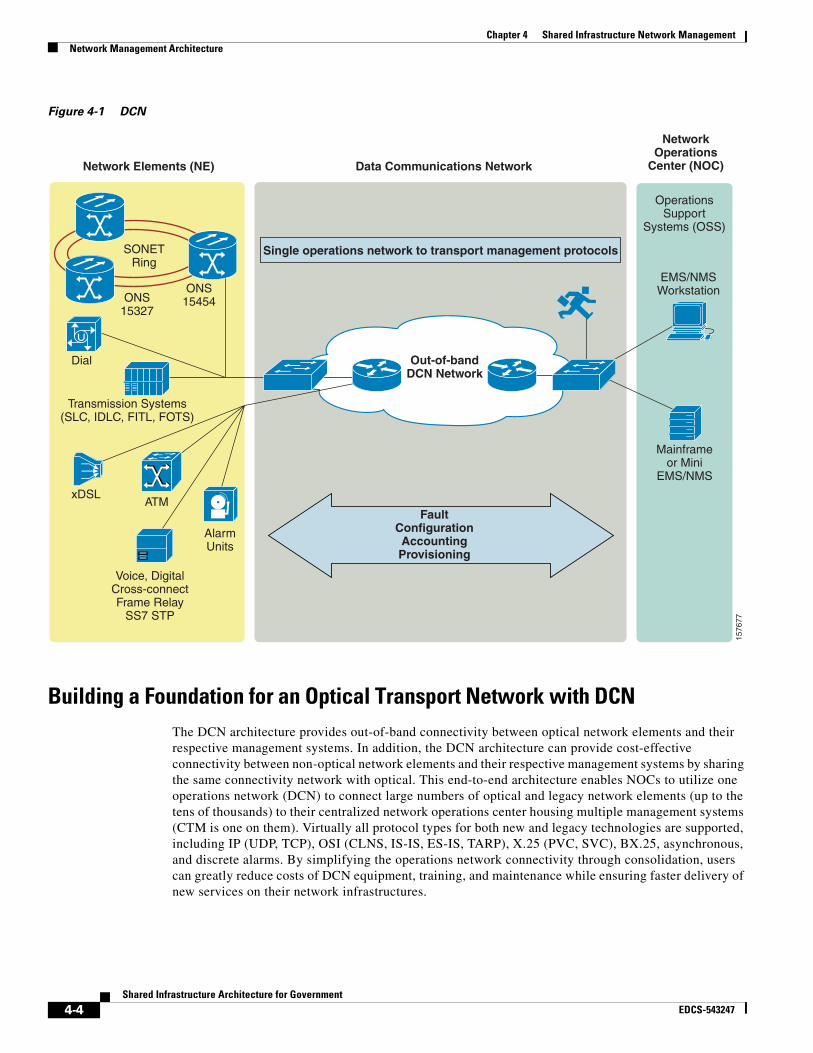
Chapter 4 Shared Infrastructure Network ManagementNetwork Management Architecture
Figure 4-1 DCN
Building a Foundation for an Optical Transport Network with DCNThe DCN architecture provides out-of-band connectivity between optical network elements and their respective management systems. In addition, the DCN architecture can provide cost-effective connectivity between non-optical network elements and their respective management systems by sharing the same connectivity network with optical. This end-to-end architecture enables NOCs to utilize one operations network (DCN) to connect large numbers of optical and legacy network elements (up to the tens of thousands) to their centralized network operations center housing multiple management systems (CTM is one on them). Virtually all protocol types for both new and legacy technologies are supported, including IP (UDP, TCP), OSI (CLNS, IS-IS, ES-IS, TARP), X.25 (PVC, SVC), BX.25, asynchronous, and discrete alarms. By simplifying the operations network connectivity through consolidation, users can greatly reduce costs of DCN equipment, training, and maintenance while ensuring faster delivery of new services on their network infrastructures.
1576
77
FaultConfigurationAccountingProvisioning
Out-of-bandDCN Network
Single operations network to transport management protocolsSONETRing
ONS15327
ONS15454
Dial
Transmission Systems(SLC, IDLC, FITL, FOTS)
xDSLATM
AlarmUnits
Voice, DigitalCross-connectFrame Relay
SS7 STP
Data Communications NetworkNetwork Elements (NE)
NetworkOperations
Center (NOC)
OperationsSupport
Systems (OSS)
EMS/NMSWorkstation
Mainframeor Mini
EMS/NMS
4-4Shared Infrastructure Architecture for Government
EDCS-543247

Chapter 4 Shared Infrastructure Network ManagementNetwork Management Architecture
Figure 4-2 DCN Optical Transport Network
The traffic that resides on a DCN is very low as it includes only element provisioning, network traffic statistics, SNMP (if desired), key management (if desired), network monitoring (Remote Monitoring, etc.), and real-time element management such as port activation/deactivation, key activation/deactivation, traffic trending, and anomaly detection and reporting, etc. Since this network is considered to be a “closed” network, practically any network element management traffic that the user considers necessary can be placed on the DCN with little risk of security threats.
DCN
DCNRouter
Cisco3600
Cisco Data Communications Network
SNMP TL1 Corba SQL
SNMP Gateway TL1 Gateway Corba Database
Operations Sport System(Order Management, Customer Care, Trouble Management, Billing, etc.)
Third Party NMS/OSS(e.g. Telcordia NMA, TEMS)
Cisco Transport Manager(Optical Transport Domain Manager)
1576
78
SONET/SDH
ONS15327
ONS15800
AlarmVoice Switch
ONS15200
Cisco Optical Transport(ONS 15xxx) Network
ONS15454
4-5Shared Infrastructure Architecture for Government
EDCS-543247
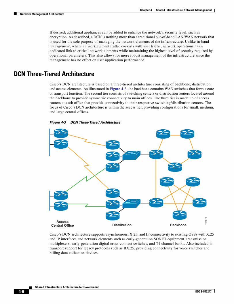
Chapter 4 Shared Infrastructure Network ManagementNetwork Management Architecture
If desired, additional appliances can be added to enhance the network’s security level, such as encryption. As described, a DCN is nothing more than a traditional out-of-band LAN/WAN network that is used for the sole purpose of managing the network elements of the infrastructure. Unlike in-band management, where network element traffic coexists with user traffic, network operations has a dedicated link to critical network elements while maintaining the highest level of security required by operational parameters. This also allows for more robust management of the infrastructure since the management has no effect on user application performance.
DCN Three-Tiered ArchitectureCisco’s DCN architecture is based on a three-tiered architecture consisting of backbone, distribution, and access elements. As illustrated in Figure 4-3, the backbone contains WAN switches that form a core or transport function. The second tier consists of switching centers or distribution routers located around the backbone to provide symmetric connectivity to main offices. The third tier is made up of access routers at each office that provide connectivity to their respective switching/distribution centers. The focus of Cisco’s DCN architecture is within the access tier, providing configurations for small, medium, and large central offices.
Figure 4-3 DCN Three-Tiered Architecture
Cisco’s DCN architecture supports asynchronous, X.25, and IP connectivity to existing OSSs with X.25 and IP interfaces and network elements such as early-generation SONET equipment, transmission multiplexers, early-generation digital cross-connect switches, and T1 channel banks. Also included is transport support for legacy protocols such as BX.25, providing connectivity for voice switches and billing data collection devices.
1576
79
AccessCentral Office Distribution Backbone
4-6Shared Infrastructure Architecture for Government
EDCS-543247

Chapter 4 Shared Infrastructure Network ManagementNetwork Management Architecture
Figure 4-4 Cisco’s DCN Architecture
This type of management implementation may be useful in our Agriculture Department example. The IT department of the Agriculture Department would connect a management port (VLAN) of every network appliance it owned and managed into the management VLAN (DCN). This segments all user traffic. It also prevents unauthorized users from accessing any network device that is maintained by the provider because there is no physical or logical path to the management ports of these devices.
This does not prevent each department or agency from using the network to manage their network devices. Their traffic and management functions can be completely independent from the network provider’s management systems. This allows the user to make changes to their network without affecting the larger provider network.
1576
77
SONET/SDHDWDM
GNE
Dial
Transmission Systems(SLC, IDLC, FITL, FOTS)
DSLATM
AlarmUnits
Voice, DigitalCross-connectFrame Relay
SS7 STP
Data Communications NetworkNetwork Elements (NE)
NetworkOperations
Center (NOC)
OperationsSupport
Systems (OSS)
Workstation
Mainframeor Mini
DCN
OSS to NE Connectivity
ISR 3303TDM
ADM
ADM
IP/OSI, ASYNC,X.25 (XOT)
FR, ATM, T1/E1
4-7Shared Infrastructure Architecture for Government
EDCS-543247

Chapter 4 Shared Infrastructure Network ManagementNetwork Management Architecture
4-8Shared Infrastructure Architecture for Government
EDCS-543247
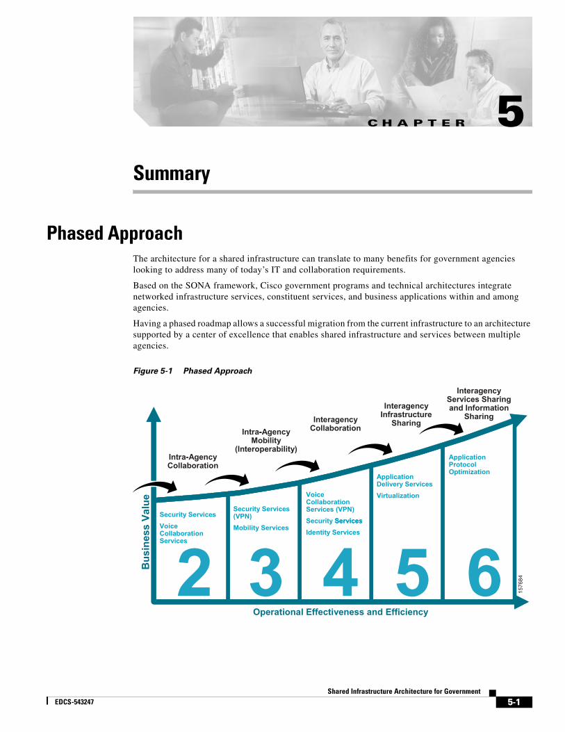
Shared InfrEDCS-543247
C H A P T E R 5
SummaryPhased ApproachThe architecture for a shared infrastructure can translate to many benefits for government agencies looking to address many of today’s IT and collaboration requirements.
Based on the SONA framework, Cisco government programs and technical architectures integrate networked infrastructure services, constituent services, and business applications within and among agencies.
Having a phased roadmap allows a successful migration from the current infrastructure to an architecture supported by a center of excellence that enables shared infrastructure and services between multiple agencies.
Figure 5-1 Phased Approach
1576
84
Intra-Agency Collaboration
Interagency CollaborationIntra-Agency
Mobility (Interoperability)
2 3 4 5 6Security ServicesVoice Collaboration Services
Security Services (VPN)Mobility Services
Voice Collaboration Services (VPN)Security ServicesIdentity Services
Application Delivery ServicesVirtualization
Application Protocol Optimization
Interagency Infrastructure
Sharing
Interagency Services Sharing and Information
Sharing
Operational Effectiveness and Efficiency
Bus
ines
s Va
lue
-
-
Services
5-1astructure Architecture for Government
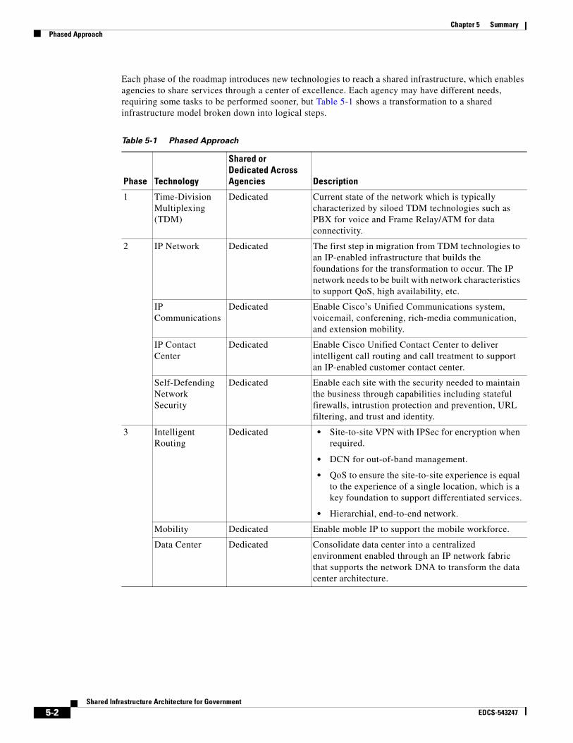
Chapter 5 SummaryPhased Approach
Each phase of the roadmap introduces new technologies to reach a shared infrastructure, which enables agencies to share services through a center of excellence. Each agency may have different needs, requiring some tasks to be performed sooner, but Table 5-1 shows a transformation to a shared infrastructure model broken down into logical steps.
Table 5-1 Phased Approach
Phase Technology
Shared or Dedicated Across Agencies Description
1 Time-Division Multiplexing (TDM)
Dedicated Current state of the network which is typically characterized by siloed TDM technologies such as PBX for voice and Frame Relay/ATM for data connectivity.
2 IP Network Dedicated The first step in migration from TDM technologies to an IP-enabled infrastructure that builds the foundations for the transformation to occur. The IP network needs to be built with network characteristics to support QoS, high availability, etc.
IP Communications
Dedicated Enable Cisco’s Unified Communications system, voicemail, conferening, rich-media communication, and extension mobility.
IP Contact Center
Dedicated Enable Cisco Unified Contact Center to deliver intelligent call routing and call treatment to support an IP-enabled customer contact center.
Self-Defending Network Security
Dedicated Enable each site with the security needed to maintain the business through capabilities including stateful firewalls, intrustion protection and prevention, URL filtering, and trust and identity.
3 Intelligent Routing
Dedicated • Site-to-site VPN with IPSec for encryption when required.
• DCN for out-of-band management.
• QoS to ensure the site-to-site experience is equal to the experience of a single location, which is a key foundation to support differentiated services.
• Hierarchial, end-to-end network.
Mobility Dedicated Enable moble IP to support the mobile workforce.
Data Center Dedicated Consolidate data center into a centralized environment enabled through an IP network fabric that supports the network DNA to transform the data center architecture.
5-2Shared Infrastructure Architecture for Government
EDCS-543247

Chapter 5 SummaryPhased Approach
Having this structured approach is critical to achieving the business benefits that governments can gain. A different look at the same roadmap (Figure 5-2) shows the business value gained through this shared infrastructure approach.
4 Intelligent Routing
Shared Enable virtualization and segmentation of the intelligent routing layer to support shared infrastructure resources across multiple agencies.
Self-Defending Network Security
Shared Virtualize security features such as firewall into the network to support multiple agencies.
Data Center Dedicated Enable data center consolidation with the server and storage fabric.
5 IP Communications
Shared Enable Cisco Hosted Unified Communications to truly virtualize IP Communications and through the centralized environment support voicemail, conferencing, and other rich-media communication for multiple agencies.
IP Contact Center
Shared Enable the Cisco Hosted Unified Contact Center to virtualize the IP contact center for multiple agencies.
Data Center Shared Consolidate data center functions across multiple agencies and introduce application acceleration and load balancing.
6 Data Center Shared Virtualize data center functions across multiple agencies and introduce application protocol optimization/translation.
Table 5-1 Phased Approach
Phase Technology
Shared or Dedicated Across Agencies Description
5-3Shared Infrastructure Architecture for Government
EDCS-543247
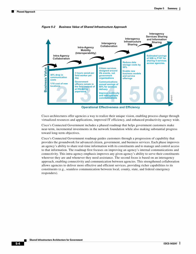
Chapter 5 SummaryPhased Approach
Figure 5-2 Business Value of Shared Infrastructure Approach
Cisco architectures offer agencies a way to realize their unique vision, enabling process change through virtualized resources and applications, improved IT efficiency, and enhanced productivity agency wide.
Cisco’s Connected Government includes a phased roadmap that helps government customers make near-term, incremental investments in the network foundation while also making substantial progress toward long-term objectives.
Cisco’s Connected Government roadmap guides customers through a progression of capability that provides the groundwork for advanced citizen, government, and business services. Each phase improves an agency’s ability to share real-time information with its constituents and to manage and control access to that information. The roadmap first focuses on improving an agency’s internal communications and connectivity. This intra-agency emphasis improves any given agency’s ability to serve their constituents wherever they are and whenever they need assistance. The second focus is based on an interagency approach, enabling connectivity and communication between agencies. This strengthened collaboration allows agencies to deliver more effective and efficient services, providing richer capabilities to its constituents (e.g., seamless communication between local, county, state, and federal emergency responders).
1910
17
Intra-Agency Collaboration
Interagency CollaborationIntra-Agency
Mobility (Interoperability)
2 3 4 5 630% drop in communication costs1/10 cost of new locations
3 hours saved per field worker per dayGovernment officers remain in the field instead of at HQ doing paperwork
Citizen services designed around life events, not government organizationsCommunications annual savings of 80% for services deliveryImprove continuity and interoperable communications
Reduce data storage costs by 50%Enable new business models and service offerings
Estimated savings of $5B in FY07 for sharing 5 services across agencies.
Interagency Infrastructure
Sharing
Interagency Services Sharing and Information
Sharing
Operational Effectiveness and Efficiency
Bus
ines
s Va
lue
5-4Shared Infrastructure Architecture for Government
EDCS-543247
Shared InfrEDCS-543247
A P P E N D I X A
Design ConsiderationsIntroductionThis appendix contains the following sections:
• VRF Technology Overview
• Routing Protocols
• Mobility
• MPLS
• Goals in QoS
• Hierarchical Network Design
• Summary
VRF Technology OverviewA VRF consists of an IP routing table, a derived forwarding table, a set of interfaces that use the forwarding table, and a set of rules and routing protocols that determine what goes into the forwarding table.
The concept of virtualized devices is not new, as VLANs have been around for quite some time. As shown in Figure A-1, the use of VRF technology allows the customer to virtualize a network device from a Layer 3 standpoint.
A-1astructure Architecture for Government

Appendix A Design ConsiderationsVRF Technology Overview
Figure A-1 Virtualization of a Layer 3 Network Device
The next step consists of virtualizing the data paths, which is achieved by linking them between the VRFs defined on the Layer 3 devices in the network. This allows multiple logical networks to overlay the same physical infrastructure (network virtualization) as shown in Figure A-2.
1537
03
VRF
VRF
GlobalLogical or
Physical Int(Layer 3)
Logical orPhysical Int
(Layer 3)
A-2Shared Infrastructure Architecture for Government
EDCS-543247
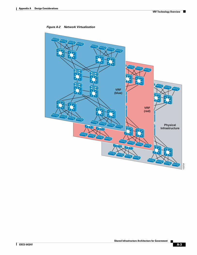
Appendix A Design ConsiderationsVRF Technology Overview
Figure A-2 Network Virtualization
1537
04
VRF(blue)
VRF(red)
PhysicalInfrastructure
A-3Shared Infrastructure Architecture for Government
EDCS-543247

Appendix A Design ConsiderationsVRF Technology Overview
Figure A-3 Segmentation Through the Enterprise Network
Several alternatives can be used to achieve network virtualization, such as GRE tunnels, 802.1q trunks, and Label Switched Paths (LSPs). Each of these methods provides a different way of achieving traffic isolation in the network.
In a shared infrastructure, traffic engineering is an important technique that can be used to handle network traffic in specific, user-defined ways. It refers to directing traffic through the network over certain paths based on characteristics of the traffic. As opposed to traditional routing, which typically uses only destination addresses for determining the route a packet follows, traffic engineering allows other parameters, such as QoS requirements, to be taken into account during the routing decision. Traffic can be routed or denied based on traffic flow, IP or MAC address, application, socket number, port number, source and destination, protocol, and several other parameters. This is important when determining access security and handling sensitive information. It allows the user to force network traffic across specific links for any number of reasons such as link quality, link speed, link path (you many not wish specific traffic to flow through specific geographical locations), link provider, etc.
Traffic engineering can be done by the user (on parameters allowed by the service provider) or by the service provider. Several tools can be used to traffic engineer the network. It is important to understand how each tool works and what it is designed to do, so that when combined with other tools, the network performs as expected. It is also important to ensure the traffic is engineered end to end, from source to destination, to ensure that traffic conforms to user requirements.
1576
81
LWAPP1. Authenticate client (user, device, app) attempting to gain network access
2. Authorize onto a Segment (Virtual Network)
1. Map client VLAN to transport technology
2. Transport client traffic through isolated path
3. Terminate isolated path @ destination edge
1. Map isolated path to destination VLAN
2. Apply policy at VLAN entry point
3. Isolate Application environments
IP
GRE
VRFs
MPLS
Functions Access Control Path Isolation Policy Enforcement
Branch - Campus WAN – MAN - Campus Data Center - Campus
IPSec
MTR
L2TPV3
A-4Shared Infrastructure Architecture for Government
EDCS-543247

Appendix A Design ConsiderationsRouting Protocols
Note Cisco Systems, Inc. currently transports the majority of Internet traffic over its systems, giving the company a wealth of experience and knowledge that is leveraged throughout its business and engineering designs. As the premier routing vendor, Cisco leads the market in new protocols, such as IPv6 and Mobile IP. Cisco has been working with IPv6 since 1995, is part of the IPv6 backbone, and is a founding member of the IPv6 forum. Cisco’s public IPv6 Web site is www.cisco.com/ipv6. Cisco currently supports IPv6 protocols such as ICMPv6, OSPFv3, MBGP, RIPv6, and ISISv6, to name just a few.
Routing ProtocolsImplementation of standards provides an avenue for integration and interoperability. Legacy routing protocols such as RIP, OSPF, ISIS, and BGP must all be supported to help ensure smooth integration of products into existing infrastructures. Standards also enable support and interoperability of new protocols. In today’s high-performance networks, organizations need the freedom to implement packet forwarding and routing according to their own defined policies in a way that goes beyond traditional routing protocol concerns. Where administrative issues dictate that traffic be routed through specific paths, policy-based routing (PBR) can provide the solution. By using PBR, agencies and departments can implement policies that selectively cause packets to take different paths. PBR provides a mechanism for expressing and implementing forwarding/routing of data packets based on policies defined by network administrators. It provides a more flexible mechanism for routing packets through routers, complementing the existing mechanism provided by routing protocols.
Routers forward packets to the destination addresses based on information from static routes or dynamic routing protocols such as Routing Information Protocol (RIP), Open Shortest Path First (OSPF), Intermediate System to Intermediate System (ISIS), or Enhanced Interior Gateway Routing Protocol (Enhanced IGRP). Instead of routing by the destination address, PBR allows network administrators to determine and implement routing policies to allow or deny paths based on the following:
• Identity of a particular end system
• Application
• Protocol
• Size of packets
Policies can be defined as simply as “my network will not carry traffic from the engineering department” or as complex as “traffic originating within my network with the following characteristics will take path A, while other traffic will take path B.”
PBR also provides a mechanism to mark packets so that certain kinds of traffic receive differentiated, preferential service when used in combination with queuing techniques enabled through Cisco IOS software. These queuing techniques provide an extremely powerful, simple, and flexible tool to network managers who implement routing policies in their networks.
Traditional IP Communications allows a host to send packets to a single host (unicast transmission) or to all hosts (broadcast transmission). IP Multicast provides a third possibility, allowing a host to send packets to a subset of all hosts as a group transmission. IP Multicast allows better utilization of network bandwidth by allowing the sender to transmit traffic only once, yet going to many destinations; only the members of a specific multicast group receive the traffic.
This overview provides a brief summary of IP Multicast. First, general topics such as multicast group concept, IP Multicast addresses, and Layer 2 multicast addresses are discussed. Then intradomain multicast protocols are reviewed, such as Internet Group Management Protocol (IGMP), Cisco Group
A-5Shared Infrastructure Architecture for Government
EDCS-543247
Appendix A Design ConsiderationsRouting Protocols
Management Protocol, Protocol Independent Multicast (PIM), and Pragmatic General Multicast (PGM). Finally, interdomain protocols are covered, such as Multiprotocol Border Gateway Protocol (MBGP), Multicast Source Directory Protocol (MSDP), and Source Specific Multicast (SSM).
IP Multicast is a bandwidth-conserving technology that reduces traffic by simultaneously delivering a single stream of information to potentially thousands of recipients. Applications that take advantage of multicast include video conferencing, corporate communications, distance learning, and distribution of software, stock quotes, and news.
IP Multicast delivers application source traffic to multiple receivers, without burdening the source or the receivers, while using a minimum of network bandwidth. Multicast packets are replicated in the network at the point where paths diverge by Cisco routers enabled with PIM and other supporting multicast protocols, resulting in the most efficient delivery of data to multiple receivers.
Many alternatives to IP Multicast require the source to send more than one copy of the data. Some, such as application-level multicast, require the source to send an individual copy to each receiver. Even low-bandwidth applications can benefit from using IP Multicast when there are thousands of receivers. High-bandwidth applications, such as MPEG video, may require a large portion of the available network bandwidth for a single stream. In these applications, IP Multicast is the only way to send to more than one receiver simultaneously.
PIM is IP routing protocol-independent and can leverage whichever unicast routing protocols are used to populate the unicast routing table, including Enhanced EIGRP, OSPF, BGP, and static routes. PIM uses this unicast routing information to perform the multicast forwarding function. Although PIM is called a multicast routing protocol, it actually uses the unicast routing table to perform the RPF check function instead of building up a completely independent multicast routing table. Unlike other routing protocols, PIM does not send and receive routing updates between routers.
Sources register with the rendezvous point and then data is forwarded down the shared tree to the receivers. The edge routers learn about a particular source when they receive data packets on the shared tree from that source through the RP. The edge router then sends PIM (S, G) join messages toward that source. Each router along the reverse path compares the unicast routing metric of the rendezvous point address to the metric of the source address. If the metric for the source address is better, it forwards a PIM (S, G) join message toward the source. If the metric for the rendezvous point is the same or better, then the PIM (S, G) join message is sent in the same direction as the RP. In this case, the shared tree and the source tree are considered congruent.
IGMP SnoopingHigh performance switches can use another method to constrain the flooding of multicast traffic, IGMP Snooping. IGMP Snooping requires the LAN switch to examine, or “snoop,” some layer 3 information in the IGMP packet sent from the host to the router. When the switch hears an IGMP Report from a host for a particular multicast group, the switch adds the host's port number to the associated multicast table entry. When it hears an IGMP Leave Group message from a host, it removes the host's port from the table entry.
On the surface, this seems like a simple solution to put into practice. However, depending on the architecture of the switch, implementing IGMP Snooping may be difficult to accomplish without seriously degrading the performance of the switch. The CPU must examine every multicast frame passing through the switch just to find an occasional IGMP packet. This results in performance degradation to the switch and in extreme cases switch failure. Unfortunately, many low-cost, Layer 2 switches that have implemented IGMP snooping rather than CGMP suffer from this problem. The switch may perform IGMP Snooping just fine in a limited demo environment, but when the buyer puts it into production networks with high-bandwidth multicast streams, it melts down under load.
A-6Shared Infrastructure Architecture for Government
EDCS-543247

Appendix A Design ConsiderationsRouting Protocols
The only viable solution to this problem is a high-performance switch designed with special ASICs that can examine the Layer 3 portion of all multicast packets at line-rate to determine whether or not they are IGMP packets.
Distribution TreesIP multicast traffic flows from the source to the multicast group over a distribution tree that connects all of the sources to all of the receivers in the group. This tree may be shared by all sources (a shared-tree), or a separate distribution tree can be built for each source (a source-tree). The shared-tree may be one-way or bidirectional.
Applications send one copy of each packet using a multicast address, and the network forwards the packets to only those networks, LANs, that have receivers.
Source trees are constructed with a single path between the source and every LAN that has receivers. Shared-trees are constructed so that all sources use a common distribution tree. Shared-trees use a single location in the network to which all packets from all sources are sent and from which all packets are sent to all receivers.
These trees are loop-free. Messages are replicated only when the tree branches.
Members of multicast groups can join or leave at any time, so the distribution tree must be dynamically updated. Branches with no listeners are discarded (pruned). The type of distribution tree used and the way multicast routers interact depend on the objectives of the routing protocol, including receiver distribution, number of sources, reliability of data delivery, speed of network convergence, shared-path or source path, and if shared path, direction of data flow.
Tree Structure
Distribution trees may be formed as either source-based trees or shared trees. Source-based distribution trees build an optimal shortest-path tree rooted at the source. Each source/group pair requires its own state information, so for groups with a very large number of sources, or networks that have a very large number of groups with a large number of sources in each group, the use of source-based trees can stress the storage capability of routers.
Shared distribution trees are formed around a central router, called a rendezvous point or core, from which all traffic is distributed regardless of the location of the traffic sources. The advantage of shared distribution trees is that they do not create lots of source/group state in the routers. The disadvantage is that the path from a particular source to the receivers may be much longer, which may be important for delay-sensitive applications. The rendezvous router may also be a traffic bottleneck if there are many high data rate sources.
A-7Shared Infrastructure Architecture for Government
EDCS-543247

Appendix A Design ConsiderationsRouting Protocols
Figure A-4 Source Trees and Shared Trees
Distribution of Receivers
One criterion to determine what type of tree to use relates to whether receivers are sparsely or densely distributed throughout the network (for example, whether almost all of the routers in the network have group members on their directly attached subnetworks). If the network has receivers or members on every subnet or the receivers are closely spaced, they have a dense distribution. If the receivers are on only a few subnets and are widely spaced, they have a sparse distribution. The number of receivers does not matter; the determining factor is how close the receivers are to each other and the source.
Sparse-mode protocols use explicit join messages to set up distribution trees so that tree state is set up only on routers on the distribution tree and data packets are forwarded to only those LANs that have hosts who join the group. Sparse-mode protocols are thus also appropriate for large internetworks where dense-mode protocols would waste bandwidth by flooding packets to all parts the internetwork and then pruning back unwanted connections. Sparse-mode protocols may build either shared trees or source trees or both types of distribution trees. Sparse-mode protocols may be best compared to a magazine subscription since the distribution tree is never built unless a receiver joins (subscribes) to the group.
Dense mode protocols build only source-distribution trees. Dense mode protocols determine the location of receivers by flooding data throughout your network and then explicitly pruning off branches that do not have receivers therefore creating distribution state on every router in your network. Dense mode protocols may use fewer control messages to set up state than sparse-mode protocols, and they may be able to better guarantee delivery of data to at least some group members in the event of some network failures. Dense mode protocols may be compared to junk mail in that every network will receive a copy of the data whether they want it or not.
2202
71
Router AShared Treefrom RP
Router B
Router C RP
Source
Receiver
Source Tree(shortest path tree)
A-8Shared Infrastructure Architecture for Government
EDCS-543247
Appendix A Design ConsiderationsRouting Protocols
IP Multicast Routing ProtocolsIn addition, there are several multicast routing protocols including Protocol Independent Multicast (PIM), Core Based Trees (CBT), and Multicast Open Shortest Path First (MOSPF).
Protocol Independent Multicast (PIM)
PIM can support both dense mode and sparse mode groups. Protocol Independent Multicast (PIM) can service both shared trees and shortest path trees. PIM can also support bi-directional trees. PIM is being enhanced to support explicit joining toward sources so that once an alternative method of discovering sources is defined, PIM will be able to take advantage of it. PIM-SM (Sparse Mode) Version 2 is an IETF standard: RFC # 2362. PIM-DM (Dense Mode) is an IETF draft.
PIM uses any unicast routing protocol to build the data distribution trees. PIM is the only multicast routing protocol deployed on the Internet to distribute multicast data natively and not over a bandwidth-limited, tunneled topology.
Protocol Independent Multicast-Sparse Mode (PIM-SM)
PIM Sparse Mode can be used for any combination of sources and receivers, whether densely or sparsely populated, including topologies where senders and receivers are separated by WAN links, and/or when the stream of multicast traffic is intermittent.
• Independent of unicast routing protocols—PIM can be deployed in conjunction with any unicast routing protocol.
• Explicit-join—PIM-SM assumes that no hosts want the multicast traffic unless they specifically ask for it. It creates a shared distribution tree centered on a defined “rendezvous point” (RP) from which source traffic is relayed to the receivers. Senders first send the data to the RP, and the receiver's last-hop router sends a join message toward the RP (explicit join).
• Scalable—PIM-SM scales well to a network of any size including those with WAN links. PIM-SM domains can be efficiently and easily connected together using MBGP and MSDP to provide native multicast service over the Internet.
• Flexible—A receiver's last-hop router can switch from a PIM-SM shared tree to a source-tree or shortest-path distribution tree whenever conditions warrant it, thus combining the best features of explicit-join, shared-tree and source-tree protocols.
Protocol Independent Multicast-Dense Mode (PIM-DM)
PIM dense mode (PIM-DM) initially floods all branches of the network with data, then prunes branches with no multicast group members. PIM-DM is most effective in environments where it is likely that there will be a group member on each subnet. PIM-DM assumes that the multicast group members are densely distributed throughout the network and that bandwidth is plentiful.
PIM-DM creates source-based shortest-path distribution trees; it cannot be used to build a shared distribution tree.
A-9Shared Infrastructure Architecture for Government
EDCS-543247

Appendix A Design ConsiderationsRouting Protocols
Figure A-5 PIM-Dense Mode
Bidirectional PIM (bidir-PIM)Bidirectional PIM (bidir-PIM) is an enhancement of the PIM protocol that was designed for efficient many-to-many communications within an individual PIM domain. Multicast groups in bidirectional mode can scale to an arbitrary number of sources with only a minimal amount of additional overhead.
The shared trees that are created in PIM-SM are unidirectional. This means that a source tree must be created to bring the data stream to the rendezvous point (the root of the shared tree) and then it can be forwarded down the branches to the receivers. Source data cannot flow up the shared tree toward the RP, as this would be considered a bidirectional shared tree.
In bidirectional mode, traffic is routed only along a bidirectional shared tree that is rooted at the rendezvous point for the group. In bidir-PIM, the IP address of the rendezvous point acts as the key to having all routers establish a loop-free spanning tree topology rooted in that IP address. This IP address need not be a router address, but can be any unassigned IP address on a network that is reachable throughout the PIM domain.
MBGP provides a method for providers to distinguish which route prefixes they will use for performing multicast RPF checks. The RPF check is the fundamental mechanism that routers use to determine the paths that multicast forwarding trees follow and to successfully deliver multicast content from sources to receivers.
MSDP was developed for peering between Internet service providers (ISPs). ISPs did not want to rely on an rendezvous point maintained by a competing ISP to provide service to their customers. MSDP allows each ISP to have its own local rendezvous point and still forward and receive multicast traffic to the Internet.
MSDP enables rendezvous points to share information about active sources. Rendezvous points know about the receivers in their local domain. When rendezvous points in remote domains hear about the active sources, they can pass on that information to their local receivers and multicast data can then be forwarded between the domains. A useful feature of MSDP is that it allows each domain to maintain an
2202
72
TrafficProtocol Independent Multicast—Dense Mode
Prune
Prune
Prune
"Send to Group 1"
"I'm a memberof Group 1" "I'm a member
of Group 1"
A-10Shared Infrastructure Architecture for Government
EDCS-543247

Appendix A Design ConsiderationsRouting Protocols
independent rendezvous point that does not rely on other domains. MSDP gives the network administrators the option of selectively forwarding multicast traffic between domains or blocking particular groups or sources. PIM-SM is used to forward the traffic between the multicast domains.
The rendezvous point in each domain establishes an MSDP peering session using a TCP connection with the rendezvous points in other domains or with border routers leading to the other domains. When the rendezvous point learns about a new multicast source within its own domain (through the normal PIM register mechanism), the rendezvous point encapsulates the first data packet in a Source-Active (SA) message and sends the message to all MSDP peers. MSDP uses a modified RPF check in determining which peers should be forwarded the SA messages. This modified RPF check is done at a SA level instead of a hop-by-hop metric. The message is forwarded by each receiving peer, also using the same modified RPF check, until the message reaches every MSDP router in the internetwork-theoretically, the entire multicast Internet. If the receiving MSDP peer is a rendezvous point, and the rendezvous point has a (*, G) entry for the group in the message (that is, there is an interested receiver), the rendezvous point creates (S, G) state for the source and joins to the shortest path tree for the source. The encapsulated data is decapsulated and forwarded down the shared tree of that rendezvous point. When the packet is received by the last hop router of the receiver, the last hop router also may join the shortest path tree to the source. The MSDP speaker periodically sends messages that include all sources within the own domain of the rendezvous point.
Protocol Dependent Multicast ChoicesProtocol Dependent Multicast, in contrast to PIM, requires building routing tables that support either distance vector (e.g., Distance Vector Multicast Routing Protocol, DVMRP) or link-state (e.g., Multicast Open Shortest Path First, MOSPF) routing algorithms.
• Distance Vector Multicast Routing Protocol (DVMRP)—DVMRP was the first multicast routing protocol developed. DVMRP must calculate and exchange its own RIP-like routing metrics so it cannot take advantage of the enhancements and capabilities of advanced routing protocols such as OSPF, IS-IS and EIGRP. It is dense-mode and so must flood data throughout the network and then prune of branches so that state for every source is created on every router in your network.
• Multicast Open Shortest Path First (MOSPF)—MOSPF is an extension to the OSPF unicast routing protocol. OSPF works by having each router in a network understand all of the available links in the network. Each OSPF router calculates routes from itself to all possible destinations. MOSPF works by including multicast information in OSPF link-state advertisements so that an MOSPF router learns which multicast groups are active on which LANs. MOSPF builds a distribution tree for each source/group pair and computes a tree for active sources sending to the group. The tree state must be recomputed whenever link state change occurs. If there are many sources and/or many groups, this calculation, called the Dijkstra algorithm, must be recomputed for every source/group combination which can be very CPU intensive.
MOSPF incorporates the scalability benefits of OSPF but can only run over OSPF routing domains. It is best used when relatively few source/group pairs are active at any given time, since all routers must build each distribution tree. It does not work well where unstable links exist. It can be deployed gradually since MOSPF routers can be combined in the same routing domain with non-multicast OSPF routers. It is not widely implemented and does not support tunneling.
• Other Protocols—Other protocols exist that are designed for research purposes, such as Core Based Trees (CBT), Simple Multicast, Express Multicast, etc. CBT and Simple Multicast, a variation of CBT, support only shared trees.
EXPRESS supports source trees only and must be implemented on every host to initiate construction of the data path. EXPRESS assumes that receivers will learn about receivers via some mechanism outside of the EXPRESS protocol. EXPRESS does not use IGMP.
A-11Shared Infrastructure Architecture for Government
EDCS-543247
Appendix A Design ConsiderationsRouting Protocols
Reverse Path Forwarding (RPF)
Reverse Path Forwarding (RPF) is an algorithm used for forwarding multicast datagrams. The algorithm works as follows:
• The packet has arrived on the RPF interface if a router receives it on an interface that it uses to send unicast packets to the source.
• If the packet arrives on the RPF interface, the router forwards it out the interfaces that are present in the outgoing interface list of a multicast routing table entry.
• If the packet does not arrive on the RPF interface, the packet is silently discarded to avoid loop-backs.
If a PIM router has source tree state, it does the RPF check using the source IP address of the multicast packet. If a PIM router has shared tree state, it uses the RPF check on the rendezvous point's (RP) address (which is known when members join the group).
Sparse-mode PIM uses the RPF lookup function to determine where it needs to send Joins and Prunes. Shared-tree state joins are sent towards the RP. Source-tree state joins are sent towards the source.
Dense-mode DVMRP and PIM groups use only source-rooted trees and make use of RPF forwarding as described above. MOSPF does not necessarily use RPF since it can compute both forward and reverse shortest path source-rooted trees by using the Dijkstra computation.
Interdomain Multicast Routing
Multicast Border Gateway Protocol
Multicast Border Gateway Protocol (MBGP) offers a method for providers to distinguish which prefixes they will use for performing multicast reverse path forwarding (RPF) checks. The RPF check is fundamental in establishing multicast forwarding trees and moving multicast content successfully from source to receiver(s).
MBGP is based on RFC 2283, Multiprotocol Extensions for BGP-4. This brings along all of the administrative machinery that providers and customers like in their inter-domain routing environment. Examples include all of the AS machinery and the tools to operate on it (e.g., route maps). Therefore, by using MBGP, any network utilizing internal or external BGP can apply the multiple policy control knobs familiar in BGP to specify routing (and therefore forwarding) policy for multicast.
Two path attributes, MP_REACH_NLRI and MP_UNREACH_NLRI, are introduced to yield BGP4+ as described in Internet Draft draft-ietf-idr-bgp4-multiprotocol-01.txt. MBGP is a simple way to carry two sets of routes-one set for unicast routing and one set for multicast routing. The routes associated with multicast routing are used by the multicast routing protocols to build data distribution trees.
The advantages are that an internet can support non-congruent unicast and multicast topologies and, when the unicast and multicast topologies are congruent, can support differing policies. MBGP provides for scalable policy-based inter-domain routing that can be used to support non-congruent unicast and multicast forwarding paths.
Multicast Source Discovery Protocol
Multicast Source Discovery Protocol (MSDP) is a mechanism to connect PIM-SM domains to enable forwarding of multicast traffic between domains while allowing each domain to use its own independent rendezvous points (RPs) and not rely on RPs in other domains.
A-12Shared Infrastructure Architecture for Government
EDCS-543247

Appendix A Design ConsiderationsMobility
The RP in each domain establishes an MSDP peering session using a TCP connection with the RPs in other domains or with border routers leading to the other domains. When the RP learns about a new multicast source within its own domain (through the normal PIM register mechanism), the RP encapsulates the first data packet in a Session Advertisement (SA) and sends the SA to all MSDP peers. The SA is forwarded by each receiving peer using a modified RPF check, until it reaches every MSDP router in the internet. If the MSDP peer is an RP, and the RP has a (*,G) entry for the group in the SA, the RP will create (S,G) state for the source and join to the shortest path for the source. The encapsulated packet is decapsulated and forwarded down that RPs shared-tree. When the packet is received by a receiver's last hop router, the last-hop may also join the shortest path to the source. The source's RP periodically sends SAs which include all sources within that RP’s own domain.
MSDP peers may be configured to cache SAs to reduce join latency when a new receiver joins a group within the cache.
Reliable Multicast—Pragmatic General MulticastReliable multicast protocols overcome the limitations of unreliable multicast datagram delivery and expand the use of IP multicast. IP multicast is based on UDP in which no acknowledgments are returned to the sender. The sender therefore does not know if the data it sends are being received, and the receiver cannot request that lost or corrupted packets be retransmitted. Multimedia audio and video applications generally do not require reliable multicast, since these transmissions are tolerant of a low level of loss. However, some multicast applications require reliable delivery.
Some elements that are relevant to deciding whether reliable multicast is applicable include the degree of reliability required, requirements for bandwidth and for ordered packet delivery, the burstiness of data, delay tolerance, timing (real-time vs. non-real-time), the network infrastructure (LAN, WAN, Internet, satellite, dial-up), heterogeneity of links in the distribution tree, router capabilities, number of senders and size of multicast group, scalability, and group setup protocol.
Cisco currently delivers Pragmatic General Multicast (PGM) as the reliable multicast solution. Implementation of PGM uses negative-acknowledgments to provide a reliable multicast transport for applications that require ordered, duplicate-free, multicast data delivery from multiple sources to multiple receivers. PGM guarantees that a receiver in the group either receives all data packets from transmissions and retransmissions, or is able to detect unrecoverable data packet loss. PGM is specifically intended as a workable solution for multicast applications with basic reliability requirements. Its central design goal is simplicity of operation with due regard for scalability and network efficiency.
Reliable multicast will be useful in areas where loss is not tolerated or where a high-degree of fidelity is required, as for example, in such areas as bulk data transfer, inventory updates, financial stock quotes, data conferencing, hybrid broadcasting (Whiteboard), software distribution, push (Webserver content), data replication, caching, and distributed simulation. Reliable multicast applications are also frequently deployed over satellite networks with terrestrial (e.g., Internet) back channels.
MobilityMobile IP is an open standard, defined by the Internet Engineering Task Force (IETF) RFC 2002, that allows users to keep the same IP address, stay connected, and maintain ongoing applications while roaming between IP networks. Mobile IP is scalable for the Internet because it is based on IP—any media that can support IP can support Mobile IP.
A-13Shared Infrastructure Architecture for Government
EDCS-543247

Appendix A Design ConsiderationsMPLS
In IP networks, routing is based on stationary IP addresses, similar to how a postal letter is delivered to the fixed address on an envelope. A device on a network is reachable through normal IP routing by the IP address it is assigned on the network.
The problem occurs when a device roams away from its home network and is no longer reachable using normal IP routing. This results in the active sessions of the device being terminated. Mobile IP was created to enable users to keep the same IP address while traveling to a different network (which may even be on a different wireless operator), ensuring that a roaming individual could continue communication without sessions or connections being dropped.
Because the mobility functions of Mobile IP are performed at the network layer rather than the physical layer, the mobile device can span different types of wireless networks while maintaining connections and ongoing applications. Remote login, remote printing, and file transfers are some examples of applications where it is undesirable to interrupt communications while an individual roams across network boundaries. Also, certain network services, such as software licenses and access privileges, are based on IP addresses. Changing these IP addresses could compromise the network services.
Network mobility is enabled by Mobile IP, which provides a scalable, transparent, and secure architecture. It is scalable because only the participating components need to be Mobile-IP aware—the mobile node and the endpoints of the tunnel. No other routers in the network or any hosts with which the mobile node is communicating need to be changed or even aware of the movement of the mobile node. It is transparent to any applications while providing mobility. Also, the network layer provides link-layer independence, interlink layer roaming, and link-layer transparency. Finally, it is secure because the setup of packet redirection is authenticated.
MPLSMPLS complements IP technology. It is designed to leverage the intelligence associated with IP routing and the switching paradigm associated with ATM. MPLS consists of a control plane and a forwarding plane. The control plane builds what is called a forwarding table, while the forwarding plane forwards packets to the appropriate interface (based on the forwarding table).
The efficient design of MPLS uses labels to encapsulate IP packets. A forwarding table lists label values, which are each associated with determining the outgoing interface for every network prefix. Cisco IOS Software supports two signaling mechanisms to distribute labels: Label Distribution Protocol (LDP) and Resource Reservation Protocol/Traffic Engineering (RSVPTE).
MPLS TE was initially envisioned as technology that would enable service providers to better utilize the available network bandwidth by using alternate paths (i.e., other than the shortest path). It has evolved to provide multiple benefits, including connectivity protection using fast reroute and tight QoS. Tight QoS results from using MPLS TE and QoS mechanisms together.
MPLS TE uses IGP, IS-IS, and OSPF to flood bandwidth information through a network. It also uses RSVP extensions to distribute labels and constraint-based routing to compute paths in the network. These extensions are defined in RFC3209.
Service providers that deploy MPLS TE tend to deploy a full mesh of TE tunnels. This creates a logical mesh, even when a physical topology is not a full mesh. In this environment, service providers have noticed an additional 40% to 50% bandwidth availability on the network. This gain is optimal network usage, which leads to a reduction in CapEx.
MPLS TE provides connectivity protection using FRR. FRR protects primary tunnels by using pre-provisioned backup tunnels. During a failure condition, it takes approximately 50 milliseconds for the primary tunnel to switch over to the backup tunnel. FRR is dependent on Layer 3 protection, unlike SONET or SDH protection that occurs at the interface level. The restoration time is therefore dependent on the number of tunnels and the number of prefixes being switched over.
A-14Shared Infrastructure Architecture for Government
EDCS-543247
Appendix A Design ConsiderationsGoals in QoS
Today’s government agencies are deploying applications that require guaranteed levels of service in the network. Voice, video, as well as control systems and other mission-critical applications will not tolerate the delays and packet loss of a best-effort network. To meet the needs of these applications, agencies are turning to QoS mechanisms in their networks. The next section examines the state of QoS tools in the networking industry today and discusses how they can be deployed to protect mission-critical applications.
Goals in QoSQoS in a shared network infrastructure is essential to provide the service levels required by and contracted for by customers or tenants. It is also essential to maintain the health of the network to help ensure traffic is transported or dropped based on the policies established by the provider.
QoS tools aim to provide preferred, and in some cases guaranteed, service to certain applications in the network. Typically network characteristics such as latency, jitter, and packet loss are the main concerns of these tools as they work to protect mission critical applications. Although packet loss, and its effect on applications, is the most commonly thought of negative attribute of networks, latency and jitter may not be as well understood.
Latency is defined as the end-to-end delay in the network from one endpoint to another. There are two types of latency that need to be considered when designing a network, static latency and dynamic latency. Static latency values do not change from one moment to the next and is the easiest to deal with when designing a network. This type of delay includes propagation delay and serialization delay. Dynamic latency can, and does, change from one moment to the next. This type of delay includes forwarding delay and buffering delay.
Jitter indicates the change in delay. For example, imagine two endpoints on a network. Endpoint A sends a packet to endpoint B. The delay for this packet is 100 milliseconds. Endpoint A then sends a second packet to endpoint B that takes 125 milliseconds. The difference between these values is the jitter, 25 millisecondsin this example. Due to its very dynamic nature, jitter is much more difficult to control and its effects can be devastating to real-time applications such as voice and video.
The primary cause of delay in networks is congestion. In a congestion-free network, every packet gets services immediately by the switches and routers in the network and there is no need for QoS. Unfortunately, networks are designed to be inherently oversubscribed and congestion is almost inevitable. It is important to note that congestion has no relationship to the backplane speed of the devices in the network. Even switches with the most powerful backplanes will experience congestion and must be capable of supporting QoS tools. Hence, QoS aims at buffer management of the network devices.
There are two categories of tools that are available to assist with congestion, congestion avoidance mechanisms and congestion control mechanisms. As their names imply, congestion avoidance mechanisms aim to prevent congestion and congestion control mechanisms help mediate the effects of congestion when it occurs.
• Congestion avoidance—Random Early Detect (RED) and Weighted Random Early Detect (WRED)
• Congestion control—Priority Queuing (PQ), Class-Based Queuing (CQ), Weighted Fair Queuing (WFQ), and Low-Latency Queuing (LLQ)
A-15Shared Infrastructure Architecture for Government
EDCS-543247

Appendix A Design ConsiderationsGoals in QoS
Bandwidth, delay, jitter, and packet loss can be effectively controlled. By ensuring the desired results, QoS features lead to efficient, predictable services for business-critical applications.
Using the QoS feature set, agencies can build networks that conform to either the IETF Integrated Services (IntServ) model and/or the Differentiated Services (DiffServ) model. QoS features also provide value-added functionality such as network-based application recognition (NBAR) for classifying traffic on an application basis, a service assurance agent (SAA) for end-to-end QoS measurements, and RSVP signaling for admission control and reservation of resources.
Cisco IOS QoS tools are divided into six main categories:
• Classification and marking—Packet classification features allow traffic to be partitioned into multiple priority levels or classes of service. This is useful when an application such as voice or a specific department, agency, or customer traffic needs to be handled in specific manners. Packets can be classified in a variety of ways—ranging from input interface, to NBAR for difficult-to-classify applications, to arbitrary ACLs. Classification is the first component of the Modular QoS CLI (MQC), the simple, scalable, and powerful QoS framework in Cisco IOS Software. The MQC allows for the clear separation of classification, from the policy applied on the classes to the application of a QoS policy on an interface or sub-interface. You can also mark packets in a variety of ways (Layer 2-802.1p/Q / ISL, ATM CLP bit, Frame-Relay DE-bit, MPLS EXP bits, etc., and Layer 3- IP Precedence, Differentiated Services Code Point [DSCP], etc.) using the policy-framework component of the MQC.
• Congestion avoidance—The WRED algorithm provides for congestion avoidance on network interfaces by offering buffer management and allowing TCP traffic to throttle back before buffers are exhausted. This helps avoid tail-drops and global synchronization issues, thereby maximizing network utilization and TCP-based application performance. The policy-framework component of the MQC accommodates WRED, which is beneficial in preventing one application, department, or agency from consuming the available network bandwidth.
Table A-1 Congestion Avoidance and Congestion Control
PQ CQ WFQ PQWFQ CBWFQLLQ
(PQ-CBWFQ)
Classification Protocol, interface
Protocol, interface
IP Prec, RSVP, RTP Reserve, protocol, port
VoFR and IP RTP Priority
Mod CLI VoFR and Mod CLI
Number of queues
4 16 Per flow 1 PQ + WFQ 64 classes 1 PQ + CBWFQ
Scheduling Strict priority
Round-robin Fair (weight, arrival time)
PQ: Strict WFQ: Fair
Fair: weight and bandwidth
PQ: Strict CBWFQ: Fair/bandwidth
Delay guarantee
Yes No No Yes No Yes
Bandwidth guarantee
No No No PQ: yes WFQ: no
Yes Yes
Used for voice
No No Last resort Yes No Yes
A-16Shared Infrastructure Architecture for Government
EDCS-543247

Appendix A Design ConsiderationsGoals in QoS
• Congestion Management—Often a network interface is congested (even at high speeds, transient congestion is observed) and queueing techniques are necessary to ensure that the critical applications get the required forwarding treatment. For example, real-time applications such as VoIP, stock-trading, etc., may need to be forwarded with the least latency and jitter (up to a provisioned limit). Cisco’s LLQ provides for such a solution. For other non-delay sensitive traffic (such as FTP, HTTP, etc.), other queuing techniques, such as CBWFQ and Modified Deficit Round-Robin (MDRR), may be used. The queueing techniques can be instantiated using the policy-framework of the MQC as well. This tool allows the provider to specify on a per agency, department, or customer basis which traffic should be transmitted first.
• Traffic conditioning—Traffic entering a network can be conditioned by using a policer or shaper. A policer simply enforces a rate limit, while a shaper smooths the traffic flow to a specified rate by the use of buffers. Once again, mechanisms such as Committed Access Rate (CAR), Generic Traffic Shaping (GTS), and Frame-Relay Traffic Shaping (FRTS) can be configured without/within the MQC framework. This tool is valuable to the network provider in preventing a user from using more than the agreed upon bandwidth. Traffic over the limit is simply dropped, forcing the transmitter to resend the information with policing. This is typically done on the ingress side (provider side) of the network. Shaping or smoothing is typically done on the egress side (customer side) to ensure the agreed upon bandwidth parameter is not exceeded.
Traffic shaping and policing are both mechanisms that can be used to ensure that a given traffic type or flow does not exceed a specified rate. The difference between traffic shaping and traffic policing lies in what is done with the traffic that exceeds the specified rate. Generally, traffic shaping buffers traffic that exceeds a specified rate and transmits it as it can.
Caution should be used when deploying traffic shaping in a network that transports latency-sensitive traffic. Increased delay can be incurred by the buffering mechanism of traffic shaping, causing adverse behavior in mission-critical applications. An example of traffic shaping is CAR.
Traffic policing, in its most basic form, discards any traffic that exceeds the specified rate.
• Signaling—Cisco IOS Software, in addition to supporting provisioned QoS (including the IETF Derentiated Services [DiffServ] model with techniques such as CAR, GTS, Layer 3 packet marking, etc.), also provides for the IETF Integrated Services (IntServ) model. RSVP is the primary mechanism for performing admission control for flows in a network. An ideal example is VoIP. A call is completed only if the resources are available for it, ensuring that a call coming into a network does not bump or affect the quality of existing calls. Another technique called QoS Policy Propagation via BGP (QPPB) allows for indirectly signaling (using the community-list attribute in BGP) the forwarding priority for packets destined toward an autonomous system, AS-path, or IP-prefix. This is a highly useful feature for service providers and large enterprises.
• Link efficiency mechanisms—Streaming video and voice traffic use the RTP. IP, UDP, and RTP packet headers can be compressed from approximately 40 bytes to 5-8 bytes. This saves a tremendous amount of bandwidth in the case of low-speed links and when supporting a large number of media streams. In addition, FRF.12 (Frame-Relay Forum specification for frame-fragmentation) and Cisco Link Fragmentation & Interleaving (LFI) allow for fragmenting large data packets, interleaving them with RTP packets, and maintaining low delay and jitter for media streams.
There are two broad categories of QoS tools available today:
• IntServ
• DiffServ
These techniques try to deliver the same preference for high-priority traffic, but use vastly different mechanisms. IntServ is a signaling-based mechanism that gives applications the ability to negotiate a contract with the network, guaranteeing that their needs are met. DiffServ is a mechanism that defines simple labels for distinguishing between packets from different applications, so that priority can be given to important traffic.
A-17Shared Infrastructure Architecture for Government
EDCS-543247

Appendix A Design ConsiderationsGoals in QoS
IntServIntServ is a technique that allows applications and end stations to request levels of service from the network. This is useful in that the end stations negotiate with each other and the network to establish transmission parameters for that stream. IntServ follows the signaled-QoS model, where the end-hosts signal their QoS needs to the network. The most common application of IntServ is the RSVP. RSVP allows requests to be made for characteristics such as bandwidth, latency, and jitter. These requests are made on behalf of an application and sent to the network where they are processed. The network devices along the path to the destination (switches, routers, etc.) examine the request and compare its requirements against the available resources. If all devices along the path to the destination can meet the request, then the network accepts it and the application can be assured that the parameters of its request will be met. If the network cannot meet the request, then it is rejected and the application must change its requirements and resignal the network.
DiffServDiffServ is a packet-tagging scheme that labels packets relative to one another. These labels are then used during times of network congestion to make queuing and discard decisions. DiffServ works on the provisioned-QoS model where network elements are set up to service multiple classes of traffic with varying QoS requirements. DiffServ actually got its start in the first iterations of the TCP/IP protocol in the 1970s. The Type of Service field in the IP header contains three bits that can be used to label packets. These values, now called IP Precedence, are in wide use today to provide priority to mission-critical applications.
In the mid 1990s, the IEEE formed a working group to expand the capabilities of IP Precedence. That group, the Differentiated Services Working Group, defined a total of 6 bits in the Type of Service field of the IP header to be the Differentiated Services Code Point (DSCP). This expanded number of bits allows for 64 classes to be defined for application differentiation. Thirty-two DSCPs are reserved for future use and thirty-two are available for use today. The DSCPs are broken into 3 different Per Hop Behaviors (PHBs): Expedited Forwarding, Assured Forwarding, and Default PHBs. The Default PHB has the lowest priority (0) and is handled as best-effort traffic. The Expedited Forwarding PHB is the highest-priority traffic (46) and receives prioritized handling in the network.
IntServ or DiffServ—Which to Deploy?DiffServ is the most widely deployed QoS model in networks today. This section examines why the differentiated services model has become so popular and how and why the IntServ model is resurfacing.
DiffServ services mechanisms, namely IP Precedence values, have been around since IP was developed in the 1970s. Those bits, however, went unused for more than two decades since applications on the network did not require different levels of service.
The IETF completed the request for comments (RFCs) for DiffServ toward the end of 1998. As stated in the DiffServ working group objectives [Ref-C], “There is a clear need for relatively simple and coarse methods of providing differentiated classes of service for Internet traffic, to support various types of applications, and specific business requirements. The differentiated service approach to providing quality of service in networks employs a small, well-defined set of building blocks from which a variety of aggregate behaviors may be built. A small bit-pattern in each packet, in the IPv4 To octet or the IPv6 Traffic Class octet, is used to mark a packet to receive a particular forwarding treatment, or per-hop behavior, at each network node.
A-18Shared Infrastructure Architecture for Government
EDCS-543247
Appendix A Design ConsiderationsGoals in QoS
A common understanding about the use and interpretation of this bit-pattern is required for inter-domain use, multi-vendor interoperability, and consistent reasoning about expected aggregate behaviors in a network. Thus, the working group has standardized a common layout for a six-bit field of both octets, called the DS field. RFC 2474 and RFC 2475 define the architecture, and the general use of bits within the DS field (superseding the IPv4 ToS octet definitions of RFC 1349).”
To deliver end-to-end QoS, this architecture (RFC-2475) has two major components, Packet Marking using the IPv4 ToS byte and PHBs.
Packet Marking
Unlike the IP Precedence architecture, the ToS byte is completely redefined. Six bits are now used to classify packets. The field is now called the DS (Differentiated Services) Field, with two of the bits unused (RFC-2474). The 6 bits replace the three IP Precedence bits and is called the DSCP. With DSCP, in any given node, up to 64 different aggregates/classes can be supported (2^6). All classification and QoS revolves around the DSCP in the DiffServ model.
PHBs
Now that packets can be marked using the DSCP, how do we provide meaningful classification on flows (CoS) and provide the required QoS? First, the collection of packets that have the same DSCP value (also called a codepoint) in them and crossing in a particular direction is called a Behavior Aggregate (BA). Thus, packets from multiple applications/sources could belong to the same BA. Formally, RFC-2475 defines a PHB as the externally observable forwarding behavior applied at a DS-compliant node to a DS behavior aggregate. In more concrete terms, a PHB refers to the packet scheduling, queuing, policing, or shaping behavior of a node on any given packet belonging to a BA and as configured by an SLA or policy. To date, four standard PHBs are available to construct a DiffServ-enabled network and achieve coarse-grained, end-to-end CoS and QoS:
Default PHB (Defined in RFC-2474)
The default PHB essentially specifies that a packet marked with a DSCP value (recommended) of ‘000000’ gets the traditional best effort service from a DS-compliant node (a network node that complies to all the core DiffServ requirements). Also, if a packet arrives at a DS-compliant node and its DSCP value is not mapped to any of the other PHBs, it is mapped to the default PHB.
Class-Selector PHBs (Defined in RFC-2474)
To preserve backward compatibility with the IP Precedence scheme, DSCP values of the form ‘xxx000’ where x is either 0 or 1, are defined. These codepoints are called class-selector codepoints. Note that the default codepoint is also is also a class-selector codepoint (‘000000’). The PHB associated with a class-selector codepoint is a class-selector PHB. These PHBs retain almost the same forwarding behavior as nodes that implement IP Precedence-based classification and forwarding.
As an example, packets with a DSCP value of ‘110000’ (IP Precedence 110) have a preferential forwarding treatment (scheduling, queuing, etc.) as compared to packets with a DSCP value of ‘100000’ (IP Precedence 100). These PHBs ensure that DS-compliant nodes can co-exist with IP Precedence aware nodes, with the exception of the DTS bits.
A-19Shared Infrastructure Architecture for Government
EDCS-543247

Appendix A Design ConsiderationsGoals in QoS
Expedited Forwarding PHB (Defined in RFC-2598)
Just as RSVP, via the IntServ model, provides for a guaranteed bandwidth service, the Expedited Forwarding (EF) PHB is the key ingredient in DiffServ for providing a low-loss, low-latency, low-jitter, and assured bandwidth service. Applications such as VoIP, video, and online trading programs require such a robust network treatment. EF can be implemented using priority queuing, along with rate limiting on the class (formally, a BA). Although EF PHB, when implemented in a DiffServ network, provides a premium service, it should be specifically targeted toward the most critical applications, since if congestion exists, it is not possible to treat all or most traffic as high priority. EF PHB is especially suitable for applications (like VoIP) that require very low packet loss, guaranteed bandwidth, low delay, and low jitter. The recommended DSCP value for EF is ‘101110’ (RFC-2474).
Assured Forwarding PHB (Defined in RFC-2597)
The rough equivalent of the IntServ Controlled Load Service is the Assured Forwarding (AFxy) PHB. It defines a method by which BAs can be given different forwarding assurances. For example, traffic can be divided into gold, silver, and bronze classes, with gold being allocated 50 percent of the available link bandwidth, silver 30 percent, and bronze 20 percent.
The AFxy PHB defines four AFx classes, AF1, AF2, AF3, and AF4. Each class is assigned a certain amount of buffer space and interface bandwidth, dependent on the SLA with the service provider/policy. Within each AFx class, it is possible to specify three drop precedence values. Thus, if there is congestion in a DS-node on a specific link, and packets of a particular AFx class (say AF1) need to be dropped, packets in AFxy are dropped such that the dP(AFx1) <= dP(AFx2) <= dp(AFx3), where dP(AFxy) is the probability that packets of the AFxy class are dropped. Thus, the subscript “y” in AFxy denotes the drop precedence within an AFx class. In our example, packets in AF13 are dropped before packets in AF12 and before packets in AF11. This concept of drop precedence is useful, for example, to penalize flows within a BA that exceed the assigned bandwidth. Packets of these flows could be re-marked by a policer to a higher drop precedence. Table A-1 shows the DSCP values for each class and drop precedence. And AFx class can be denoted by the DSCP ‘xyzab0’, where ‘xyz’ is 001 / 010 / 011 / 100, and ‘ab’ represents the drop precedence bits (RFC-2597).
DiffServ Issues—The ChallengesAlthough DiffServ is powerful in enabling scalable and coarse-grained QoS throughout the network, it has some drawbacks which present both challenges for tomorrow and opportunities for enhancements and simplification of QoS delivery:
• Provisioning—Unlike RSVP/IntServ, DiffServ needs to be provisioned. Setting up the various classes throughout the network requires knowledge of the applications and traffic statistics for aggregates of traffic on the network. This process of application discovery and profiling can be time-consuming, although tools such as NBAR application discovery, protocol analyzers, and RMON probes can simplify it a bit.
• Billing and monitoring—Management remains an issue. Even though packets/sec., bytes/sec., and many other counters are available via the class-based Management Information Base (MIB), billing and monitoring are still difficult. For example, it may not be sufficient to prove to a customer that 9 million VoIP packets got the EF PHB treatment at all times, since it is possible that the qualitative nature of the calls that the customer made were very poor.
• Loss of granularity—Even though QoS assurances are being made at the class level, it may be necessary to drill down to the flow level to provide the requisite QoS. For example, although all HTTP traffic may have been classified as gold and assigned a bandwidth of 100Mbps, there is no
A-20Shared Infrastructure Architecture for Government
EDCS-543247

Appendix A Design ConsiderationsGoals in QoS
inherent mechanism to ensure that a single flow does not use up that allocated bandwidth. It is also not easy (although not impossible) to ensure that, for example, the manufacturing department’s HTTP traffic gets priority before another department’s HTTP traffic. The MQC allows you to define hierarchical policies to accomplish this, however it is not generic enough to control it at a flow/granular level.
• QoS and routing—One of the biggest drawbacks of both the IntServ and DiffServ models derives from the fact that signaling/provisioning happens separately from the routing process. Thus, there may exist a path (other than the non-default IGP, such as OSPF, ISIS, EIGRP, and so on)/EGP, such as BGP-4, path in the network that has the required resources, even when RSVP/DiffServ fails to find the resources. This is where traffic engineering and MPLS come into play. True QoS with maximum network utilization will arrive with the marriage of traditional QoS and routing.
IntServ, in the form of RSVP, was very prevalent in the media in the mid 1990s. However ATM and RSVP were difficult to deploy and very cumbersome to manage. RSVP began to run into scalability issues in the core of networks where devices had to keep track of hundreds of thousands of reservations (and their associated flows), as well as switching packets.
The IETF-defined models, IntServ and DiffServ, are simply two ways of considering the fundamental problem of providing QoS for a given IP packet. The IntServ model relies on RSVP to signal and reserve the desired QoS for each flow in the network. A flow is defined as an individual, unidirectional data stream between two applications and is uniquely identified by the 5-tuple (Source IP address, Source Port#, Destination IP address, Destination Port#, and the Transport Protocol). Two types of service can be requested via RSVP (assuming all network devices support RSVP along the path from the source to the destination). The first type is a very strict guaranteed service that provides for firm bounds on end-to-end delay and assured bandwidth for traffic that conforms to the reserved specifications. The second type is a controlled load service that provides for a better-than-best effort and low-delay service under light to moderate network loads. Thus it is possible (at least theoretically) to provide the requisite QoS for every flow in the network, provided it is signaled using RSVP and the resources are available. However there are several practical drawbacks to this approach:
• Every device along a packet’s path, including the end systems like servers and PCs, need to be fully aware of RSVP and capable of signaling the required QoS.
• Reservations in each device along the path are “soft,” which means they need to be refreshed periodically, thereby adding to the traffic on the network and increasing the chance that the reservation may time out if refresh packets are lost. Though some mechanisms alleviate this problem, it adds to the complexity of the RSVP solution.
• Maintaining soft-states in each router, combined with admission control at each hop, adds to the complexity of each network node along the path and increased memory requirements to support large numbers of reservations.
• Since state information for each reservation needs to be maintained at every router along the path, scalability with hundreds of thousands of flows through a network core becomes an issue.
DiffServ offered an alternative that was easier to deploy and manage and was able to scale to the largest networks. Although DiffServ has the ability to offer different levels of service to applications, it offers no guaranteed delivery of data. Because of this, the networking industry has turned back towards IntServ as the future of QoS.
A-21Shared Infrastructure Architecture for Government
EDCS-543247
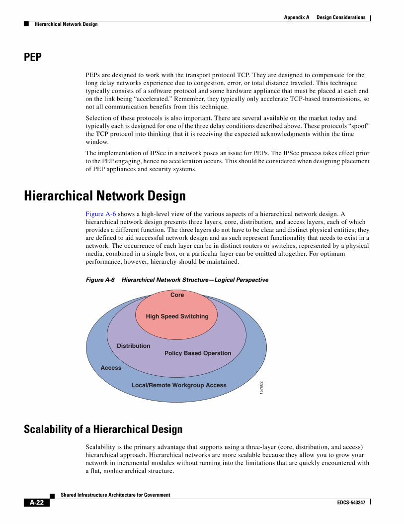
Appendix A Design ConsiderationsHierarchical Network Design
PEPPEPs are designed to work with the transport protocol TCP. They are designed to compensate for the long delay networks experience due to congestion, error, or total distance traveled. This technique typically consists of a software protocol and some hardware appliance that must be placed at each end on the link being “accelerated.” Remember, they typically only accelerate TCP-based transmissions, so not all communication benefits from this technique.
Selection of these protocols is also important. There are several available on the market today and typically each is designed for one of the three delay conditions described above. These protocols “spoof” the TCP protocol into thinking that it is receiving the expected acknowledgments within the time window.
The implementation of IPSec in a network poses an issue for PEPs. The IPSec process takes effect prior to the PEP engaging, hence no acceleration occurs. This should be considered when designing placement of PEP appliances and security systems.
Hierarchical Network DesignFigure A-6 shows a high-level view of the various aspects of a hierarchical network design. A hierarchical network design presents three layers, core, distribution, and access layers, each of which provides a different function. The three layers do not have to be clear and distinct physical entities; they are defined to aid successful network design and as such represent functionality that needs to exist in a network. The occurrence of each layer can be in distinct routers or switches, represented by a physical media, combined in a single box, or a particular layer can be omitted altogether. For optimum performance, however, hierarchy should be maintained.
Figure A-6 Hierarchical Network Structure—Logical Perspective
Scalability of a Hierarchical DesignScalability is the primary advantage that supports using a three-layer (core, distribution, and access) hierarchical approach. Hierarchical networks are more scalable because they allow you to grow your network in incremental modules without running into the limitations that are quickly encountered with a flat, nonhierarchical structure.
1576
82
Core
High Speed Switching
DistributionPolicy Based Operation
Local/Remote Workgroup Access
Access
A-22Shared Infrastructure Architecture for Government
EDCS-543247

Appendix A Design ConsiderationsHierarchical Network Design
Hierarchical designs offer several operational and management advantages which are requirements for large scale networks:
• Internetwork simplicity—Adopting a hierarchical design reduces the overall complexity of a network by partitioning elements into smaller units. This partitioning of elements makes troubleshooting easier while providing inherent protection against the propagation of broadcast storms, routing loops, or other potential problems.
• Design flexibility—Hierarchical network designs provide greater flexibility by allowing for easy migration to newer technologies. By having distinct core, distribution, and access layers, any one layer can be upgraded without having to change the entire environment. This is key as newer technologies and requirements are identified.
• Router management—With the use of a layered, hierarchical approach to router implementation, the complexity of individual router configurations is substantially reduced because each router has fewer neighbors or peers with which to communicate. This also allows for faster convergence times so that when network changes occur, the network stabilizes much faster, resulting in a higher-performance network.
A-23Shared Infrastructure Architecture for Government
EDCS-543247
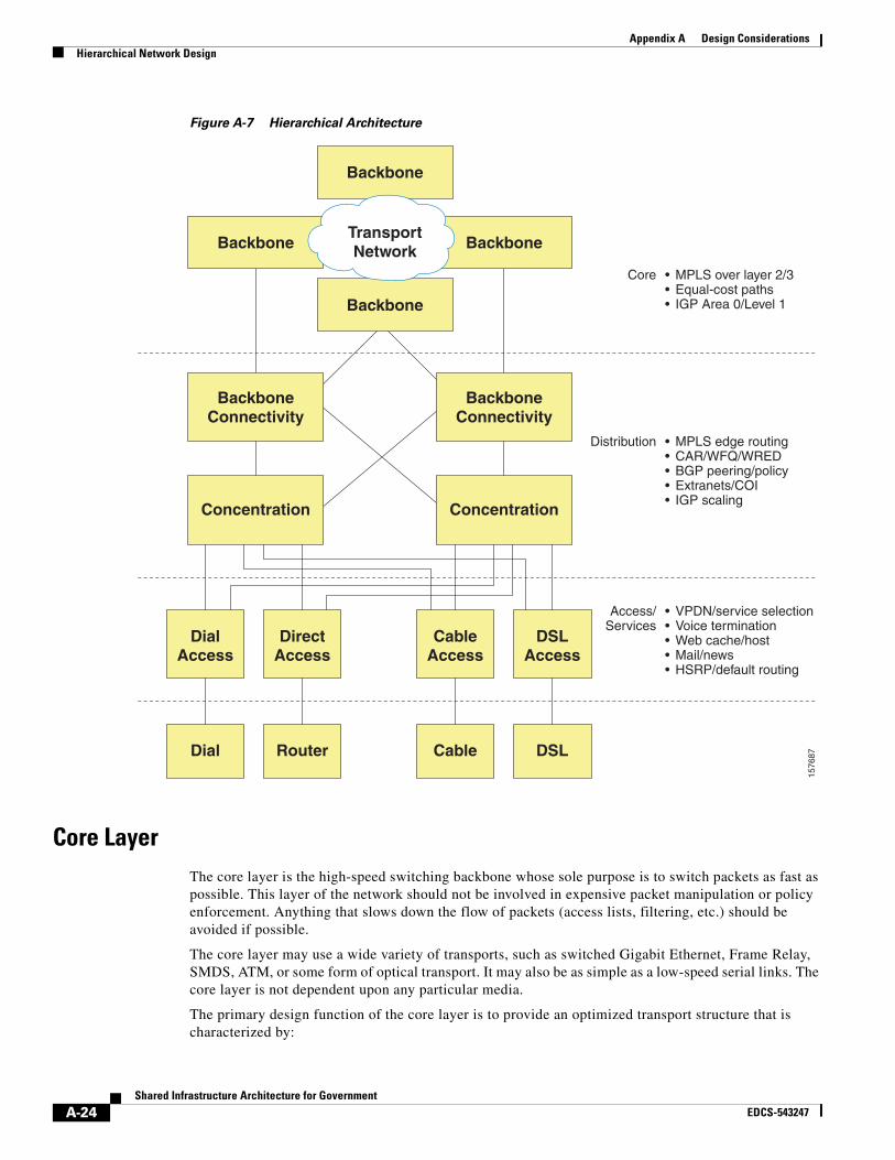
Appendix A Design ConsiderationsHierarchical Network Design
Figure A-7 Hierarchical Architecture
Core LayerThe core layer is the high-speed switching backbone whose sole purpose is to switch packets as fast as possible. This layer of the network should not be involved in expensive packet manipulation or policy enforcement. Anything that slows down the flow of packets (access lists, filtering, etc.) should be avoided if possible.
The core layer may use a wide variety of transports, such as switched Gigabit Ethernet, Frame Relay, SMDS, ATM, or some form of optical transport. It may also be as simple as a low-speed serial links. The core layer is not dependent upon any particular media.
The primary design function of the core layer is to provide an optimized transport structure that is characterized by:
Backbone
Backbone
Backbone
Backbone
BackboneConnectivity
BackboneConnectivity
ConcentrationConcentration
DialAccess
DirectAccess
CableAccess
DSLAccess
Dial Router Cable DSL
TransportNetwork
• MPLS over layer 2/3• Equal-cost paths• IGP Area 0/Level 1
Core
• MPLS edge routing• CAR/WFQ/WRED• BGP peering/policy• Extranets/COI• IGP scaling
Distribution
• VPDN/service selection• Voice termination• Web cache/host• Mail/news• HSRP/default routing
Access/Services
1576
87
A-24Shared Infrastructure Architecture for Government
EDCS-543247

Appendix A Design ConsiderationsHierarchical Network Design
• Defined network diameter and traffic patterns
• Optimized paths between interconnected sites
• Dynamic load sharing across the core structure
• Efficient and controlled use of bandwidth
All core routers should use the same routing protocol and uniform metrics. Varying routing protocols and metrics within the core creates strange effects in route convergence, use of equal cost paths, and overall latency.
Bandwidth between core routers should be equal, as this helps control latency, allows prioritization by protocol, and simplifies network tuning.
The core layer should contain alternate paths with the following caveats:
• Single circuit failures do not isolate core sites
• Multiple circuit failures do not partition the network
• Potential use of equal cost multipaths are maximized
Distribution LayerThe distribution layer of the network, the demarcation point between the access and core layers, helps define and differentiate the core. This layer provides boundary definition and is a location for the potentially expensive (CPU-intensive) packet manipulations that are best avoided in the core.
The primary design function of the distribution layer is to provide policy-based access to the core layer of the enterprise network. The distribution layer is characterized by:
• Policy-based definition of access to the core
• Policy-based definition of availability of services
• Policy-based definition of path metrics
Policy routing may also be used to determine how the access-layer devices interact with each other. Policy routing is a very flexible mechanism for routing packets. It is a process whereby the router puts packets through a route map before routing them. A policy defines the route by which packets are routed to the next router. You might enable policy routing if you want certain packets to be routed in a way other than the obvious shortest path. Some possible applications for policy routing are to provide equal access, protocol-sensitive routing, source-sensitive routing, routing based on interactive versus batch traffic, or routing based on dedicated links.
The distribution layer can represent a multitude of functions, including:
• Address or area aggregation
• Departmental or workgroup access
• Broadcast/multicast domain definition
• InterVLAN routing
• Media translations
• Security between the distribution hub and the core network
• Security between access-layer devices connected via the distribution router
• Filtering excessive protocols such as IPX SAP and IPX RIP
• Definintion of static and/or floating routes
A-25Shared Infrastructure Architecture for Government
EDCS-543247

Appendix A Design ConsiderationsHierarchical Network Design
In the non-campus environment, this layer can be a redistribution point between routing domains or the demarcation between static and dynamic routing protocols. It also should be the point at which remote sites access the corporate network.
Access LayerThe access layer of the network is the point at which end users are allowed into the network. This layer can provide further tuning and policy administration in terms of filtering or access lists, but its key function is to provide access for end users into the network.
The primary design function of the access layer is to provide access to the enterprise for a workgroup on a local segment. The access layer provides the following functionality:
• Provides logical segmentation
• Defines local user access to the enterprise network
• Provides local access to network services
• Allows for multiple paths
• Initial policies access enforced
The access layer may also provide a wide range of services such as:
• Extended addressing
• Broadcast/multicast facilities
• Locally significant filtering
• Access to naming services
• Router discovery
• Local protocol conversion
In the campus environment some of the functions represented by this layer are:
• Switched bandwidth
• MAC layer filtering (possibly)
• Microsegmentation
In the noncampus environment, this layer provides access to remote sites into the corporate network via some wide-area technology (Frame Relay, Integrated Services Digital Network [ISDN], leased line, DSL, cable modem, etc.).
ConsiderationsIn addition to the benefits of a shared infrastructure within a single building or campus that houses multiple tenants, a tenant that may have multiple locations across the world can reap rewards from a shared infrastructure. Through virtualized services, multiple locations can be connected across the network transparently as if the multiple sites were physically together. Through the VPN, virtualized storage, and many other capabilities in Cisco’s shared infrastructure offering, we bring the capabilities to support multiple tenants in a building or multi-site support for an individual tenant.
A-26Shared Infrastructure Architecture for Government
EDCS-543247

Appendix A Design ConsiderationsSummary
SummaryNetworks today are global and critical to the core operations of business and society. As such, it is important that their characteristics be understood by the network administrators. It takes many providers, partners, and vendors to establish and maintain the global network ecosystem we all depend on daily. Therefore it is critical that all participants in the network know and understand their role and expectations as it relates to network characteristics. It is also important that the networks be actively managed to assure network availability, reliability, and performance.
A-27Shared Infrastructure Architecture for Government
EDCS-543247

Appendix A Design ConsiderationsSummary
A-28Shared Infrastructure Architecture for Government
EDCS-543247

Shared InfrEDCS-543247
A P P E N D I X B
Security Terminology and StandardsSecurity Terminology • Authentication—Determining the origin of information, from an end user or a device such as a host,
server, switch, router, etc.
• Data integrity—Ensuring that data was not altered during transit
• Data confidentiality—Ensuring that only the entities allowed to see the data; see it in a usable format
• Encryption—A method of scrambling information in such a way that it is not readable by anyone except the intended recipient, who must decrypt it to read it
• Decryption—A method of unscrambling encrypted information to make it legible
• Key—A digital code that can be used to encrypt, decrypt, and sign information
• Public key—A digital code used to encrypt/decrypt information and verify digital signatures; this key can be made widely available; it has a corresponding private key
• Private key—A digital code used to decrypt/encrypt information and provide digital signatures; this key should be kept secret by its owner; it has a corresponding public key
• Secret key—A digital code that is shared by two parties; it is used to encrypt and decrypt data
• Key fingerprint—A legible code that is unique to a public key; it can be used to verify ownership of the public key
• Hash function—A mathematical computation that results in a string of bits (digital code); the function is not reversible to produce the original input
• Hash—The resulting string of bits from a hash function
• Message digest—The value returned by a hash function (same as a hash)
• Cipher—Any method of encrypting data
• Digital signature—A string of bits appended to a message (an encrypted hash) that provides authentication and data integrity
Security StandardsIt is generally recognized that the best way to manage security risk and compliance requirements is through a systematic and comprehensive approach, based on industry best practices that work within the requirements of The Committee of Sponsoring Organizations of the Treadway Commission’s (COSO) Enterprise Risk Management framework. The starting point should be a single, overarching, and
B-1astructure Architecture for Government

Appendix B Security Terminology and StandardsSecurity Standards
organization wide control framework within which all individual network security and compliance requirements can be addressed. There are two widely recognized and widely deployed IT control frameworks. The first, developed by the IT Governance Institute in America, is the Control Objectives for Information and related Technologies (COBIT). The second, developed by the International Standards Organization (ISO) with worldwide input, is ISO/IEC 17799 (supported by ISO 27001). COBIT and ISO/IEC 17799 offer good starting points and are capable of working together. Between them, they support an IT governance framework that can help organizations manage IT-related risk and network security compliance audit requirements, including PCI standard, HIPAA, and GLBA data security regulations, as well as the needs of current corporate governance and internal control regimes.
COBIT and ISO/IEC 17799 allow companies to use established best practices to simplify and unify their IT processes and internally defined controls. In support of the Sarbanes-Oxley Act, recent Public Company Accounting Oversight Board (PCOAB) guidance encourages Sarbanes-Oxley Act auditors to recognize that high-level controls can establish the validity of contributing controls, providing a formal context for deployment of an established hierarchical IT framework that could significantly streamline the auditing process. This approach “helps coordinate enterprise wide risk and compliance efforts and reduces the cost and dislocation of IT audits because if auditors can easily see how an auditee’s control framework fits together, they are likely to take up considerably less IT staff time and resources in their risk assessment effort.”1 In fact, many organizations are adopting this systematic approach worldwide.
COBIT is used primarily by the IT audit community to demonstrate risk mitigation and avoidance mechanisms deployed by technologists to the management community of an organization. In 1998, management guidelines were added and COBIT became an internationally accepted framework for IT governance by clarifying IT processes and their associated controls. ISO/IEC 17799 (The Code of Practice for Information Security Management) is an internationally recognized standard and is a best-practice framework for implementing security management. The two standards are not in competition; they complement one another. COBIT focuses on the information system's life cycle processes while ISO/IEC 17799 focuses on security. ISO/IEC 17799 addresses control objectives, while COBIT addresses information security management process requirements.
One of the most visible benefits to organizations that adhere to COBIT and ISO/IEC 17799 best practice frameworks is that by complying with and enforcing the regulatory security policies, they can reduce both human and monetary costs. The Cisco Self-Defending Network provides a “build once, deploy everywhere” paradigm capable of satisfying the companion paradigm: “validate once, comply everywhere.” The reduction of effort associated with deployment and ongoing validation—due to reusability and modularity—makes it easier to acquire, deploy, and operationalize controls and reduces costs.
In addition, application and network infrastructures constructed from a common base significantly ease the “pain” associated with audit and compliance. If the point-product-specific architectures are removed and common system, network, application, and control architectures are deployed, the effort required for compliance is dramatically reduced. Although little commonality is at first perceived between the various compliance regimes, they share an overriding element—the protection of the availability, confidentiality, and integrity of information, whether at rest, in transit, or process. The Cisco Self-Defending Network implements much of the ISO/IEC 17799 control objectives associated with the governance and operation of information security management that the business demands, while enabling a repeatable, cost-efficient justification mechanism for adherence to many of the auditor's and manager’s COBIT process requirements—fundamentally allowing for the translation of these controls into the business-risk frameworks demanded by various compliance and regulatory regimes.
1. J.L Bayuk, “Stepping through the IS Audit,” Information Systems Audit and Control Association: 2004, page 38.
B-2Shared Infrastructure Architecture for Government
EDCS-543247

Appendix B Security Terminology and StandardsSecurity Standards
COBITIT is relatively new to the auditor and is often difficult for management to understand. COBIT incorporates the concept of an overarching framework by which audits can be performed in an IT environment. Audit frameworks such as COBIT are built upon ISO/IEC 17799 for their information security components. COBIT removes the challenges of the dynamic IT landscape by focusing on processes and objectives as opposed to technological specifications, becoming a recognized framework used for many audit regimes and entities such as the Sarbanes-Oxley Act, HIPAA, the U.S. Government Accountability Office (GAO), and GLBA. Developed and promoted by the IT Governance Institute, COBIT is an open standard for IT control that benefits management, technologists, and auditors as a risk-avoidance methodology that covers the process life cycle of both an IT project and the IT infrastructure as a whole. This framework identifies 34 IT processes within four domains of control corresponding to the lifecycle of an IT project:
• Planning and organization
• Acquisition and implementation
• Delivery and support
• Monitoring
From a security perspective, the most important COBIT domain is DS5. This is a broad domain, targeted at “ensuring system security.” This is also one of the few COBIT domains where specific technology requirements are given. They are:
• Confidentiality and privacy requirements
• Authorization, authentication, and access control
• Cryptographic key management
• Incident handling, reporting, and follow-up
• Virus prevention and detection
• Firewalls
• Centralized security administration
• User training
• Tools for monitoring compliance
• Intrusion testing and reporting
• User identification and authorization to profiles
• Need-to-have and need-to-know
ISO/IEC 17799Private, fixed networks that carry sensitive data between local computers require proper security measures to protect the privacy and integrity of that traffic. However, there is more to network security than simply protecting fixed private networks. LANs and WANs must be considered, as must the VPNs and extranets that augment existing fixed private networks. Networks must also be scalable, to allow future growth to be supported quickly, easily, and inexpensively. At the same time, networks must ensure that properly authenticated users can only access the services they are authorized to access. ISO/IEC 17799 provides substantial guidance on these and other network security and compliance issues.
B-3Shared Infrastructure Architecture for Government
EDCS-543247

Appendix B Security Terminology and StandardsSecurity Standards
ISO/IEC 17799 defines a “code of practice” surrounding 132 security controls structured under 12 major headings (clauses), to enable organizations to identify the specific safeguards that are appropriate to their particular business or specific area of responsibility. These security controls contain further detailed controls bringing the number to more than 5000 controls and elements of best practice. It is important to keep in mind that the controls within ISO/IEC 17799 do not address requirements; rather, they speak toward objectives.
ISO/IEC 17799 contains best-practice control objectives and controls in the following 12 clauses of information security management. It includes a number of sections, covering a wide range of security issues. Broadly, the 12 clauses that ISO/IEC 17799 objectifies are:
• Risk assessment
• Security policy
• Organization of information security
• Asset management
• Human resources security
• Physical and environmental security
• Communications and operations management
• Access control
• Information systems acquisition, development, and maintenance
• Information security incident management
• Business continuity management
• Compliance
B-4Shared Infrastructure Architecture for Government
EDCS-543247