Embed Size (px)
Citation preview
Split Type Inverter Room Air Conditioner OPERATION MANUAL
MODELS: AY-X09NCJ AE-X09NCJ AY-X12NCJ AE-X12NCJ AY-X18NCJ AE-X18NCJ AY-X24NCJ AE-X24NCJ AY-X28NCJ AE-X28NCJ
Thank you for selecting SHARP Air-Conditioner. Please read this manual carefully before operation and keep it for further reference.
2
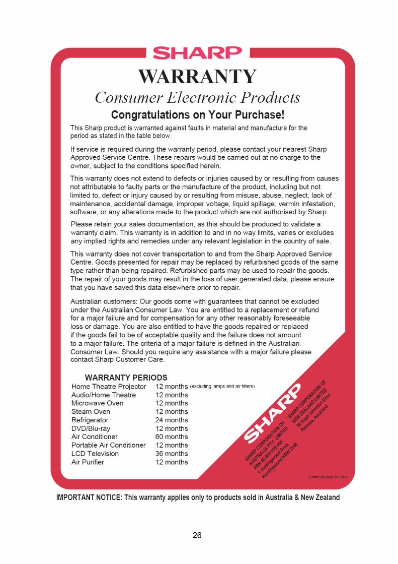
CONTENTS Operation and maintenance Notice for operation ………………………………………………. 3 Name and function of each part ………………………………… 4 Operation of wireless remote control …………………………… 5 - 8 Emergency operation …………………………………………….. 9 Care and cleaning ………………………………………………… 10 Troubleshooting …………………………………………………… 11 Operating Tips………………………………………………………...12 Notices for use ……………………………………………………. 12 Installation service Notices for installation ……………………………………………. 13 Installation dimension diagram ………………………………….. 15 Installing indoor unit ………………………………………………. 16 Installing outdoor unit …………………………………………….. 18 Test operation and check after installation …………………….. 19 Specifications ……………………………………………………… 20 Warranty Statement…………………………………………………..26 NOTE: All the pictures in this manual are just schematic diagrams. The actual product is the standard.
This symbol stands for the items that should be prevented.
This symbol stands for the items that should be followed.
Do not dispose this product as unsorted municipal waste. Collection of such waste should be separated for special treatment as required by local regulations.
3
Notices for operation Please read the following carefully before operating
The product should be installed by a licensed air conditioning contractor in accordance with AS/NZS3000:2000 and your electricity supplier’s rules. This product is designed to operate on 220-240VAC, 50Hz. Operating outside of these limits may cause damage to the product.
For safety, be sure to turn the product off at the circuit breaker before performing any maintenance or cleaning or when the product is not used for extended periods.
There are local council rules regarding the maximum allowable noise levels emitted by air conditioning units. Check with your local council before installation.
Do not leave windows and doors open for a long period while operating the air conditioner. It will decrease the air conditioning capacity.
Do not block the air intake or outlet vents of both the indoor and outdoor units. This can decrease the air conditioning capacity or cause a malfunction.
This unit is thermostatically controlled and will turn on and off automatically according to your settings. Selecting the most appropriate temperature can save electricity.
If you notice anything abnormal with the air conditioner’s operation (eg burning smell or noise), turn the
unit off immediately and disconnect from the power supply.
Keep combustible materials away from the air conditioner by at least 1.5m, as it can cause a fire or explosion.
Do not attempt to repair the air conditioner by yourself. Attempting repair could cause the risk of electric shock or fire. Please contact your local Sharp Approved Service Centre.
Please do not cut off or damage the power cords and control cords.
If they are damaged, please refer the matter to a qualified air conditioning contractor. To change the airflow direction, adjust the vertical and lateral air flow direction by using the remote control.
Do not insert your hands or objects into the air intake or outlet vents.
Do not expose animals and plants directly in front of the output air flow as it may have a detrimental effect on them.
Do not expose yourself to cold output air for prolonged periods as it may affect your health.
This air conditioner is designed for normal residential use. Do not use for any other purpose such as food preservation or drying clothes.
Splashing water on the air conditioner can cause an electric shock or malfunction.
Do not place a space heater or cooking appliance near the air conditioner.
4
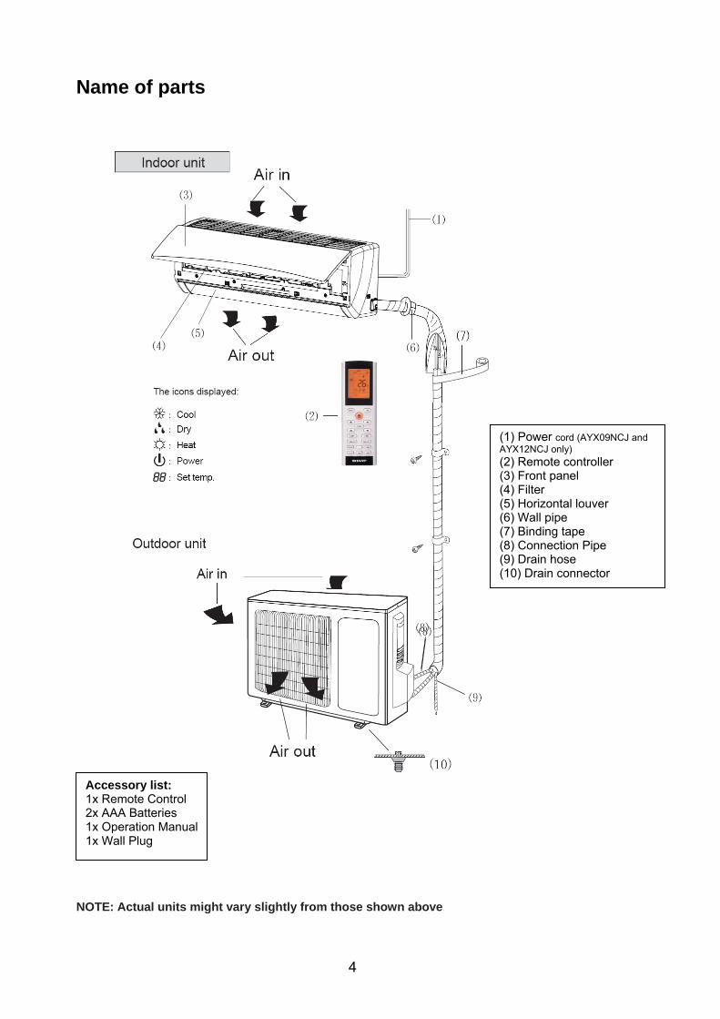
Name of parts
NOTE: Actual units might vary slightly from those shown above
(1) Power cord (AYX09NCJ and AYX12NCJ only) (2) Remote controller (3) Front panel (4) Filter (5) Horizontal louver (6) Wall pipe (7) Binding tape (8) Connection Pipe (9) Drain hose (10) Drain connector
Accessory list: 1x Remote Control 2x AAA Batteries 1x Operation Manual 1x Wall Plug
5
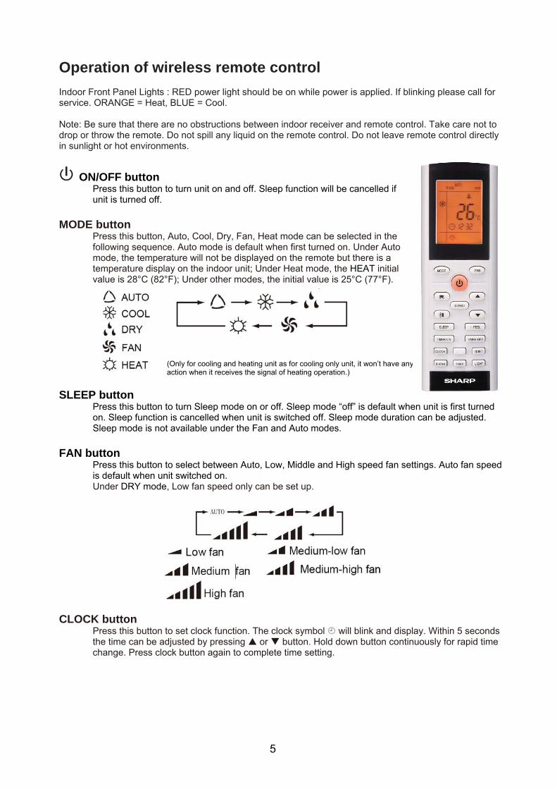
Operation of wireless remote control Indoor Front Panel Lights : RED power light should be on while power is applied. If blinking please call for service. ORANGE = Heat, BLUE = Cool. Note: Be sure that there are no obstructions between indoor receiver and remote control. Take care not to drop or throw the remote. Do not spill any liquid on the remote control. Do not leave remote control directly in sunlight or hot environments.
ON/OFF button
Press this button to turn unit on and off. Sleep function will be cancelled if unit is turned off.
MODE button
Press this button, Auto, Cool, Dry, Fan, Heat mode can be selected in the following sequence. Auto mode is default when first turned on. Under Auto mode, the temperature will not be displayed on the remote but there is a temperature display on the indoor unit; Under Heat mode, the HEAT initial value is 28°C (82°F); Under other modes, the initial value is 25°C (77°F).
SLEEP button
Press this button to turn Sleep mode on or off. Sleep mode “off” is default when unit is first turned on. Sleep function is cancelled when unit is switched off. Sleep mode duration can be adjusted. Sleep mode is not available under the Fan and Auto modes.
FAN button
Press this button to select between Auto, Low, Middle and High speed fan settings. Auto fan speed is default when unit switched on. Under DRY mode, Low fan speed only can be set up.
CLOCK button
Press this button to set clock function. The clock symbol will blink and display. Within 5 seconds the time can be adjusted by pressing or button. Hold down button continuously for rapid time change. Press clock button again to complete time setting.
(Only for cooling and heating unit as for cooling only unit, it won’t have any action when it receives the signal of heating operation.)
6
Operation of wireless remote control con’t. Note: This wireless remote control is universal, and it could be used for various units. Some buttons on this control may not be applicable to this unit.
X-FAN button
Pressing X’FAN button in COOL or DRY mode, the icon is displayed and the indoor fan will continue operation for 10 minutes in order to dry the indoor unit even though you have turned off the unit. X-FAN OFF is default. X-FAN is not available in AUTO, FAN or HEAT mode.
TURBO button
Under Cool or Heat mode the TURBO function will operate the air conditioner at maximum power. Pressing the TURBO button turns the TURBO function on or off. After the TURBO function is turned on, the TURBO signal is displayed. The signal will automatically be cancelled if mode or fan speed is changed.
and button
Preset temperature is increased and decreased by pressing these buttons. Continuously pressing and holding for 2 seconds changes the preset temperature rapidly. The preset temperature adjustment is unavailable under the Auto Mode.
LIGHT button
Press this button to turn indoor display light ON or OFF. Light ON is default when unit is switched on.
QUIET button
Press this button, the QUIET icon is under the Auto Quiet mode (display “ ” and “Auto” icon) and
QUIET mode (display “ ” icon) and QUIET OFF (there is no icon displayed). After powered on, the QUIET OFF is default.
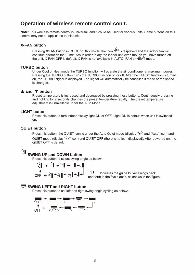
SWING UP and DOWN button Press this button to select swing angle as below:
Indicates the guide louver swings back and forth in the five places, as shown in the figure.
SWING LEFT and RIGHT button
Press this button to set left and right swing angle cycling as below:
7
Operation of wireless remote control con’t. TIMER ON button – selects or presets a time you wish the air conditioner to turn on.
Press this button to select TIMER ON setting. Pressing the or button during the first 5 seconds adjusts the time value by one minute each time pressed. Holding the or button down for more than 2 seconds changes the time rapidly. While time is blinking, press TIMER ON button to confirm setting. After setting, repressing the TIMER ON button cancels the operation. Note: To operate TIMER ON function correctly set the clock to the current time.
TIMER OFF button – selects or presets a time you wish the air conditioner to turn off.
Press this key to enter TIMER OFF setup, in which case the TIMER OFF icon will blink. The method of setting TIMER OFF is the same as TIMER ON.
TEMP button
Press this button to set up and select: setting temperature (displaying the room), indoor ambient temperature (displays current indoor temperature), outdoor ambient temperature (displays current outdoor temperature), if there is no outdoor ambient temperature the original display status will circulate as follows: No signal displayed. Remark: when operating this button the setting temperature is displayed all the time on the wireless remote control.
I FEEL button
Press this button once to turn on the I FEEL function. When the “I FEEL” symbol is displayed the remote control will send a temperature reading to the indoor unit every 10 minutes. The air conditioner will adjust accordingly to remote control location. Press the “I FEEL” button again to cancel operation.
About X-FAN function: This function indicates that the indoor fan will continue to blow after the unit is turned off so moisture in the indoor unit will be removed. This will help avoid mould. 1. Having set X-FAN function on; Turning off the unit by pressing ON/OFF button indoor fan will continue running for about 10 min. at low speed. In this period, press X-FAN button to stop indoor fan directly. 2. Having set X-FAN function off: After turning off the unit by pressing ON/OFF button, the unit will be shut down directly. About AUTO RUN function: When AUTO RUN mode is selected, the setting temperature will be displayed on the display, the unit senses the room temperature automatically to select a suitable running method for room comfort. About TURBO function: When TURBO mode is selected the unit will run at super-high fan speed to cool or heat quickly so that the ambient temperature approaches the preset temperature as soon as possible. About LOCK: Press or buttons simultaneously to lock or unlock the keypad. If the remote controller is locked, the icon will be displayed on it. In which case, press any button, the mark will flicker three times. If the keyboard is unlocked, the mark will disappear. About switch between Fahrenheit and Centigrade: Under status of unit off, press MODE and button simultaneously to switch between °C and °F. About Quiet function: If Auto Quiet mode has been selected, after the room temperature reached the setting temperature or 10mins later, the air conditioner will immediately enter into the Quiet running status, at this time the fan speed is not adjustable.
8
Operation of wireless remote control con’t. Introduction of Special Function ● Press SLEEP button to select Sleep 1 ( ), Sleep 2 ( ), Sleep 3 ( ), and cancel. Sleep cancel is default setting. ● Sleep 1 in Cool and Dry modes: after one hour, the main unit setting temperature will increase 1°C. After 2 hours the setting temperature increases to 2°C, the unit will run at this setting temperature; In Heat mode: after two hours, the setting temperature will decrease 1°C, 2 hours, setting temperature will decrease 2°C , then the unit will run at this setting temperature.
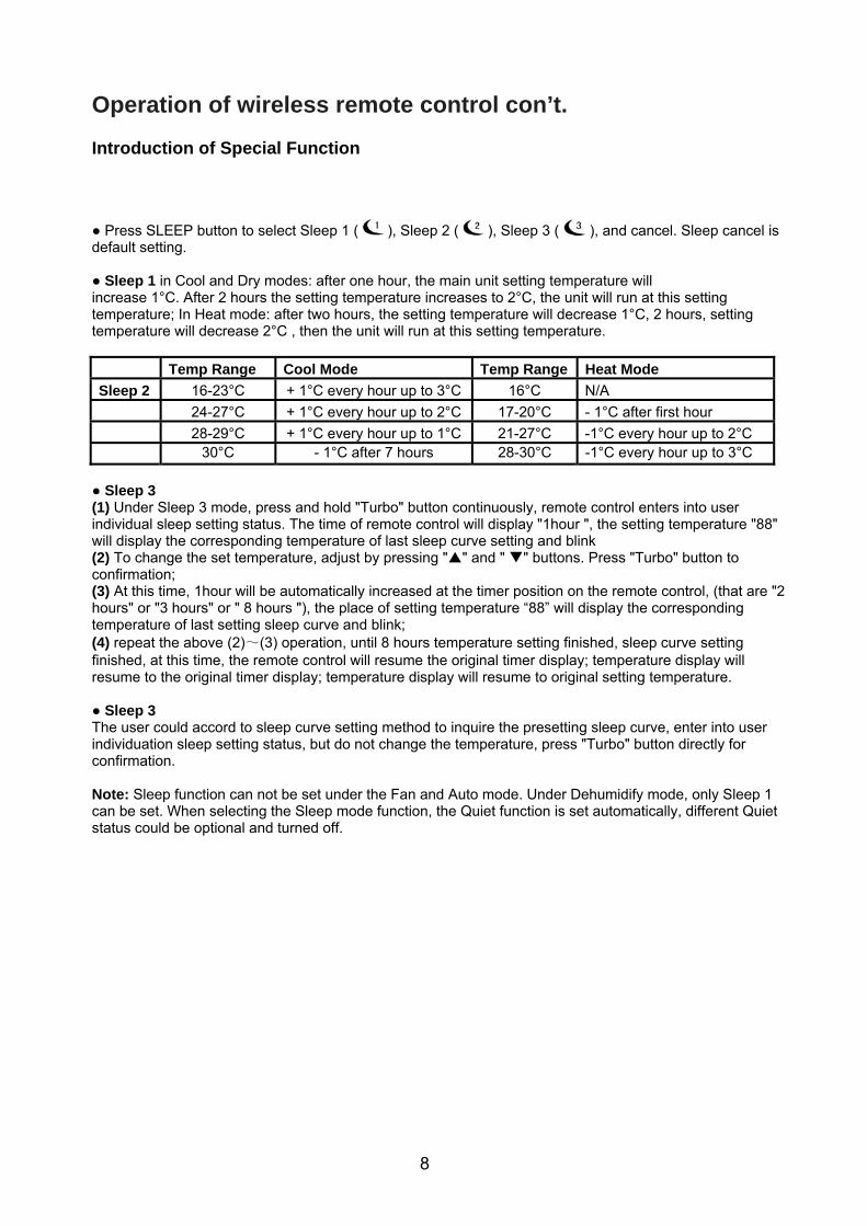
Temp Range Cool Mode Temp Range Heat Mode
Sleep 2 16-23°C + 1°C every hour up to 3°C 16°C N/A
24-27°C + 1°C every hour up to 2°C 17-20°C - 1°C after first hour
28-29°C + 1°C every hour up to 1°C 21-27°C -1°C every hour up to 2°C 30°C - 1°C after 7 hours 28-30°C -1°C every hour up to 3°C
● Sleep 3 (1) Under Sleep 3 mode, press and hold "Turbo" button continuously, remote control enters into user individual sleep setting status. The time of remote control will display "1hour ", the setting temperature "88" will display the corresponding temperature of last sleep curve setting and blink (2) To change the set temperature, adjust by pressing "" and " " buttons. Press "Turbo" button to confirmation; (3) At this time, 1hour will be automatically increased at the timer position on the remote control, (that are "2 hours" or "3 hours" or " 8 hours "), the place of setting temperature “88” will display the corresponding temperature of last setting sleep curve and blink; (4) repeat the above (2)~(3) operation, until 8 hours temperature setting finished, sleep curve setting finished, at this time, the remote control will resume the original timer display; temperature display will resume to the original timer display; temperature display will resume to original setting temperature. ● Sleep 3 The user could accord to sleep curve setting method to inquire the presetting sleep curve, enter into user individuation sleep setting status, but do not change the temperature, press "Turbo" button directly for confirmation. Note: Sleep function can not be set under the Fan and Auto mode. Under Dehumidify mode, only Sleep 1 can be set. When selecting the Sleep mode function, the Quiet function is set automatically, different Quiet status could be optional and turned off.
9
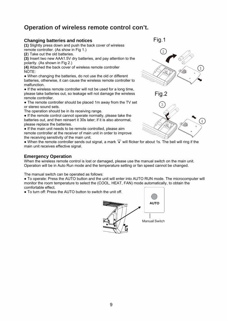
Operation of wireless remote control con’t. Changing batteries and notices (1) Slightly press down and push the back cover of wireless remote controller. (As show in Fig 1.) (2) Take out the old batteries. (3) Insert two new AAA1.5V dry batteries, and pay attention to the polarity. (As shown in Fig 2.) (4) Attached the back cover of wireless remote controller NOTE: ● When changing the batteries, do not use the old or different batteries, otherwise, it can cause the wireless remote controller to malfunction. ● If the wireless remote controller will not be used for a long time, please take batteries out, so leakage will not damage the wireless remote controller. ● The remote controller should be placed 1m away from the TV set or stereo sound sets. The operation should be in its receiving range. ● If the remote control cannot operate normally, please take the batteries out, and then reinsert it 30s later; if it is also abnormal, please replace the batteries. ● If the main unit needs to be remote controlled, please aim remote controller at the receiver of main unit in order to improve the receiving sensitivity of the main unit. ● When the remote controller sends out signal, a mark will flicker for about 1s. The bell will ring if the main unit receives effective signal. Emergency Operation When the wireless remote control is lost or damaged, please use the manual switch on the main unit. Operation will be in Auto Run mode and the temperature setting or fan speed cannot be changed. The manual switch can be operated as follows: ● To operate: Press the AUTO button and the unit will enter into AUTO RUN mode. The microcomputer will monitor the room temperature to select the (COOL, HEAT, FAN) mode automatically, to obtain the comfortable effect. ● To turn off: Press the AUTO button to switch the unit off. AUTO
10
Care and Cleaning
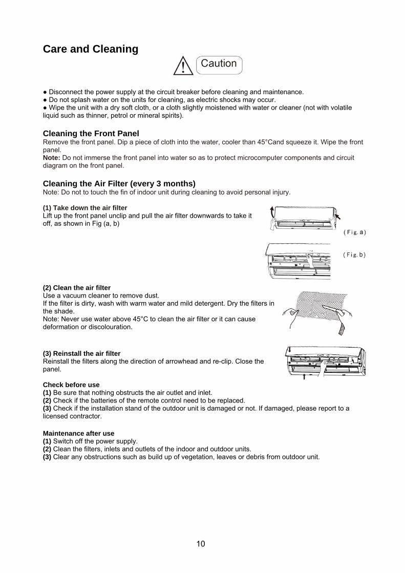
● Disconnect the power supply at the circuit breaker before cleaning and maintenance. ● Do not splash water on the units for cleaning, as electric shocks may occur. ● Wipe the unit with a dry soft cloth, or a cloth slightly moistened with water or cleaner (not with volatile liquid such as thinner, petrol or mineral spirits). Cleaning the Front Panel Remove the front panel. Dip a piece of cloth into the water, cooler than 45°Cand squeeze it. Wipe the front panel. Note: Do not immerse the front panel into water so as to protect microcomputer components and circuit diagram on the front panel. Cleaning the Air Filter (every 3 months) Note: Do not to touch the fin of indoor unit during cleaning to avoid personal injury. (1) Take down the air filter Lift up the front panel unclip and pull the air filter downwards to take it off, as shown in Fig (a, b) (2) Clean the air filter Use a vacuum cleaner to remove dust. If the filter is dirty, wash with warm water and mild detergent. Dry the filters in the shade. Note: Never use water above 45°C to clean the air filter or it can cause deformation or discolouration. (3) Reinstall the air filter Reinstall the filters along the direction of arrowhead and re-clip. Close the panel. Check before use (1) Be sure that nothing obstructs the air outlet and inlet. (2) Check if the batteries of the remote control need to be replaced. (3) Check if the installation stand of the outdoor unit is damaged or not. If damaged, please report to a licensed contractor. Maintenance after use (1) Switch off the power supply. (2) Clean the filters, inlets and outlets of the indoor and outdoor units. (3) Clear any obstructions such as build up of vegetation, leaves or debris from outdoor unit.
11
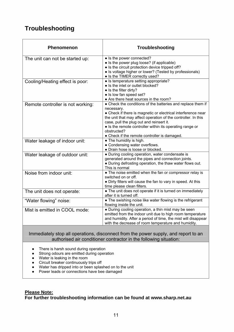
Troubleshooting
Phenomenon
Troubleshooting
The unit can not be started up: ● Is the power connected?
● Is the power plug loose? (if applicable) ● Is the circuit protection device tripped off? ● Is voltage higher or lower? (Tested by professionals) ● Is the TIMER correctly used?
Cooling/Heating effect is poor: ● Is temperature setting appropriate? ● Is the inlet or outlet blocked? ● Is the filter dirty? ● Is low fan speed set? ● Are there heat sources in the room?
Remote controller is not working: ● Check the conditions of the batteries and replace them if necessary. ● Check if there is magnetic or electrical interference near the unit that may affect operation of the controller. In this case, pull the plug out and reinsert it. ● Is the remote controller within its operating range or obstructed? ● Check if the remote controller is damaged.
Water leakage of indoor unit: ● The humidity is high. ● Condensing water overflows. ● Drain hose is loose or blocked.
Water leakage of outdoor unit: ● During cooling operation, water condensate is generated around the pipes and connection joints. ● During defrosting operation, the thaw water flows out. This is normal
Noise from indoor unit: ● The noise emitted when the fan or compressor relay is switched on or off. ● Dirty filters will cause the fan to vary in speed. At this time please clean filters.
The unit does not operate: ● The unit does not operate if it is turned on immediately after it is turned off.
“Water flowing” noise: ● The swishing noise like water flowing is the refrigerant flowing inside the unit.
Mist is emitted in COOL mode: ● During cooling operation, a thin mist may be seen emitted from the indoor unit due to high room temperature and humidity. After a period of time, the mist will disappear with the decrease of room temperature and humidity.
Immediately stop all operations, disconnect from the power supply, and report to an
authorised air conditioner contractor in the following situation: ● There is harsh sound during operation ● Strong odours are emitted during operation ● Water is leaking in the room ● Circuit breaker continuously trips off ● Water has dripped into or been splashed on to the unit ● Power leads or connections have bee damaged
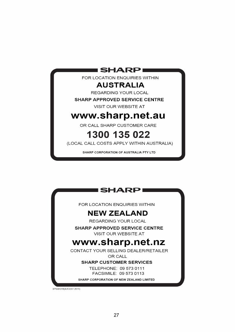
Please Note: For further troubleshooting information can be found at www.sharp.net.au
12
Operation Tips Operating Temperature Range Indoor side DB/WB (°C) Outdoor side DB/WB (°C) Maximum cooling 32 43 Maximum cooling 21 21 Maximum heating 27 24 Maximum heating 20 -5 The operating temperature range (outdoor temperature) is 15°C ~ 24°C. Tips for energy saving: (1) Do not overcool or overheat. Setting temperature at a moderate level helps energy saving. (2) Cover windows with a blind or a curtain. Blocking sunlight and air from outdoors is favourable for cooling (heating). (3) Clean air filters once per two weeks. Clogged air filters lead to inefficient operation and energy waste. Tips for relative humidity: (1) Condensate water is likely to form at the air outlet if cooling or drying for a long time when the relative humidity is more the 80% (with doors and windows open).
Notices for Use Cooling Operation Principle: (1) Air conditioners absorb heat in the room and transmit it to the outdoor unit, so that the room temperature is decreased. The cooling capacity will increase or decrease according to outdoor ambient temperature. Anti freezing Function: (2) If the unit is operating in COOL mode and in low ambient temperature, frost may be formed on the heat exchanger. When indoor heat exchanger temperature decreased below zero, compressor will stop operation to protect the unit. Heating Operation Principle: (1) Air conditioners absorb heat from outdoors and transmit it to the indoor unit, increasing room temperature. The heating capacity will decrease at low ambient temperature. Defrosting: (1) When the outdoor temperature is low but humidity is high, frost may form on the outdoor unit during extended operation, affecting heating efficiency. The air conditioner may stop operation during auto defrosting operation. (2) During auto defrosting, the fan motors of indoor unit and outdoor unit will stop. (3) During defrosting, the indoor indicator flashes and the outdoor unit may emit vapour. This is not a malfunction. (4) After defrosting is finished, the heating operation will recover automatically. Anti-cold Air Function In HEAT mode, the indoor fan will not operate in order to prevent cold air blowing out (within 2 minutes) if indoor heat exchanger doesn’t reach a certain temperature under the following three states: (1) Heating operation starts; (2) After Auto Defrosting is finished; (3) Heating at low temperature. Rest Heat Blow In the following situations, the indoor unit may still run for some time, to blow out the heat remaining in the indoor unit. (1) In HEAT mode, the temperature reached the setting value, the compressor stops and the indoor fan still run for 60s. (2) In HEAT mode, if you turn off the unit, the compressor stops and the indoor fan still runs for 10s.
13
Notices of Installation
CAUTION
(1) Before installation, please contact your local authorised installer. This unit must be installed by an authorised installer according to local or government regulations and in compliance with this manual to avoid a malfunction. (2) When relocating this unit, please contact your local authorised installer. (3) Warning: Before obtaining access to terminals, all supply circuits must be disconnected at the circuit breaker. (4) If the power cord is damaged, it must be replaced by the installer or authorised service technician in order to avoid a hazard. (5) The appliance must be positioned so that the plug is accessible (AYX09 & AYX12 Only). (6) The temperature of refrigerant circuit will be high, please keep the interconnection cable away from the copper tube. (7) This appliance is not intended for use by persons (including children) with reduced physical, sensory or mental capabilities, or lack of experience and knowledge, unless they have been given supervision or instruction concerning use of the appliance by a person responsible for their safety. Children should be supervised to ensure that they do not play with the appliance.
Installation Site Instructions Proper installation site is vital for correct and efficient operation of the unit. Avoid the following sites where: ● Strong heat sources, vapours, flammable gas or volatile liquids are emitted. ● High-frequency electro-magnetic waves are generated by radio equipment, welders and medical equipment. ● Salt-laden air prevails (such as close to coastal areas). ● The air is contaminated with industrial vapours and oils. ● Corrosion on neighbouring materials exists.
Installation Site of Indoor Unit ● The air inlet and outlet should be away from any obstructions. Ensure the air can be blown through the whole room. ● Select a site where the condensing water can be easily drained out, and where it is easily connected for outdoor unit. ● Select a place where is it out of reach of children. ● Select the place where the wall is strong enough to withstand the full weight and vibration of the unit. ● Be sure to leave enough space to allow access for routine maintenance. The installation site should be 250cm or more above the floor. ● Select a place about 1m or more away from TV set or any electric appliance. ● Select a place where the filter can be easily taken out. ● Make sure that the indoor unit is installed in accordance with the installation instructions.
Installation Site of Outdoor Unit ● Select a site where noise and outflow air emitted by unit will not annoy neighbours. ● Select a site where there is sufficient ventilation. ● Select a site where there is no obstruction blocking the inlet and outlet. ● the site should be able to withstand the full weight and vibration of the unit. ● Select a dry place, but do not expose the unit to direct sunlight or strong wind. ● Make sure that the outdoor unit is installed in accordance with the installation instructions, and access is convenient for maintenance and repair. ● Ensure that the height difference between indoor and outdoor units for the 09K is within 15M, the 12K,18K,24K & 28K is within 10m. Ensure the length of the connection tubing for 09K does not exceed 10m; for 12K does not exceed 20m, for 18K, 24K, 28K does not exceed 25m. ● Select a place where it is out of reach of children. ● Select a place which will not block pedestrian passage.
14
Notices of Installation con’t.
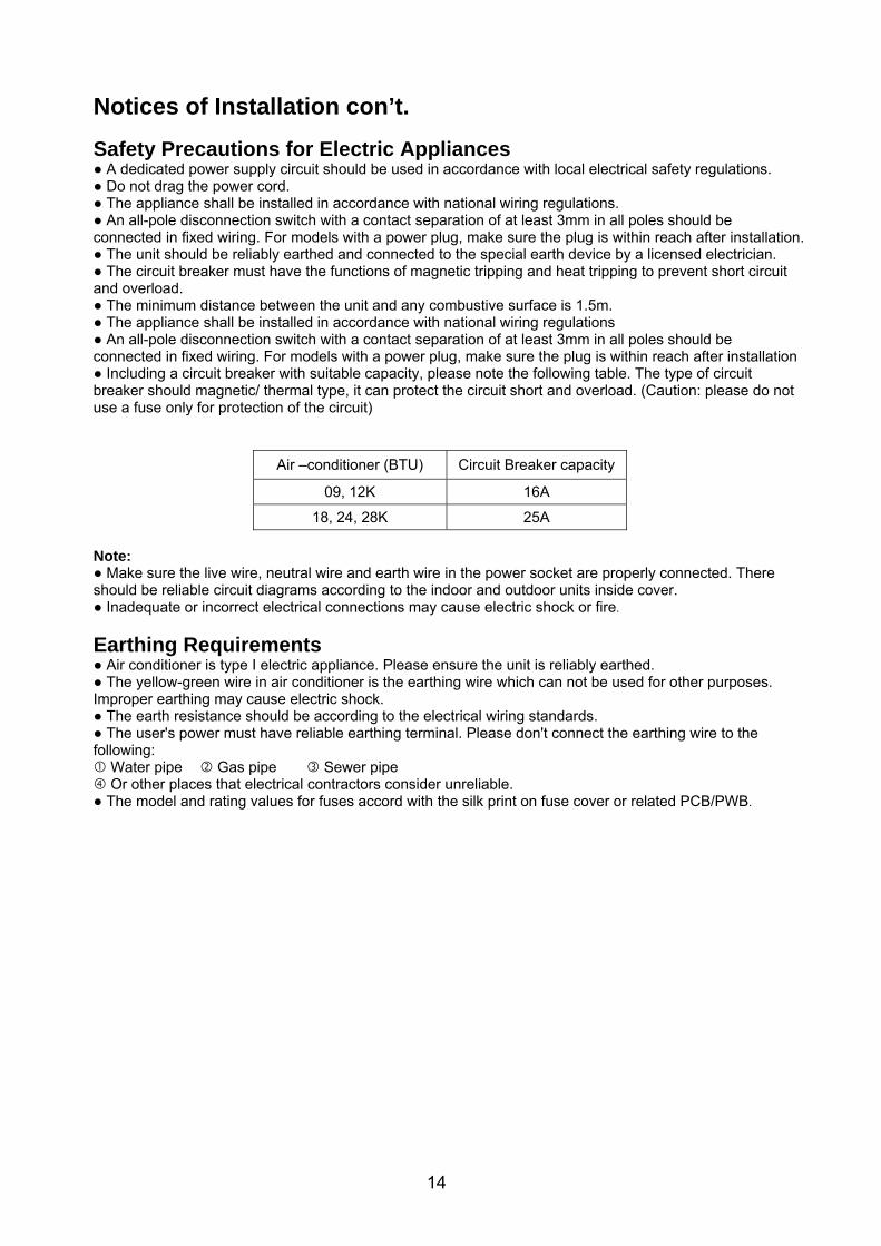
Safety Precautions for Electric Appliances ● A dedicated power supply circuit should be used in accordance with local electrical safety regulations. ● Do not drag the power cord. ● The appliance shall be installed in accordance with national wiring regulations. ● An all-pole disconnection switch with a contact separation of at least 3mm in all poles should be connected in fixed wiring. For models with a power plug, make sure the plug is within reach after installation. ● The unit should be reliably earthed and connected to the special earth device by a licensed electrician. ● The circuit breaker must have the functions of magnetic tripping and heat tripping to prevent short circuit and overload. ● The minimum distance between the unit and any combustive surface is 1.5m. ● The appliance shall be installed in accordance with national wiring regulations ● An all-pole disconnection switch with a contact separation of at least 3mm in all poles should be connected in fixed wiring. For models with a power plug, make sure the plug is within reach after installation ● Including a circuit breaker with suitable capacity, please note the following table. The type of circuit breaker should magnetic/ thermal type, it can protect the circuit short and overload. (Caution: please do not use a fuse only for protection of the circuit)
Air –conditioner (BTU) Circuit Breaker capacity
09, 12K 16A
18, 24, 28K 25A
Note: ● Make sure the live wire, neutral wire and earth wire in the power socket are properly connected. There should be reliable circuit diagrams according to the indoor and outdoor units inside cover. ● Inadequate or incorrect electrical connections may cause electric shock or fire.
Earthing Requirements ● Air conditioner is type I electric appliance. Please ensure the unit is reliably earthed. ● The yellow-green wire in air conditioner is the earthing wire which can not be used for other purposes. Improper earthing may cause electric shock. ● The earth resistance should be according to the electrical wiring standards. ● The user's power must have reliable earthing terminal. Please don't connect the earthing wire to the following: Water pipe Gas pipe Sewer pipe Or other places that electrical contractors consider unreliable. ● The model and rating values for fuses accord with the silk print on fuse cover or related PCB/PWB.
15
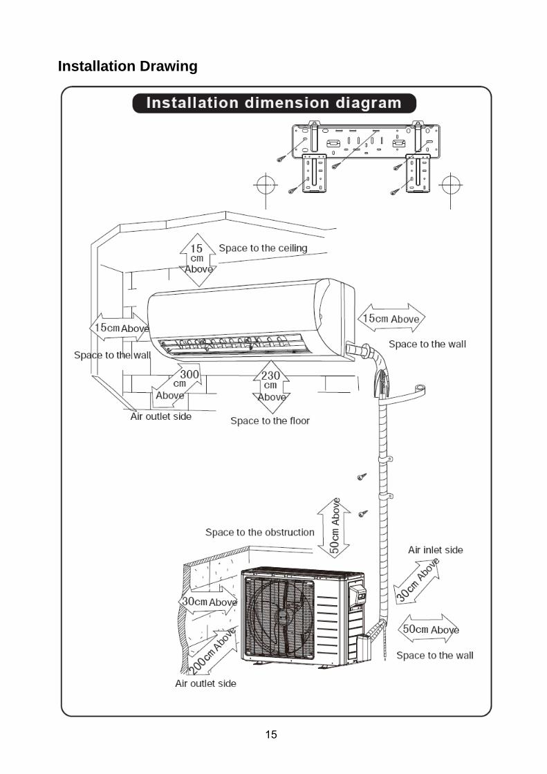
Installation Drawing
16
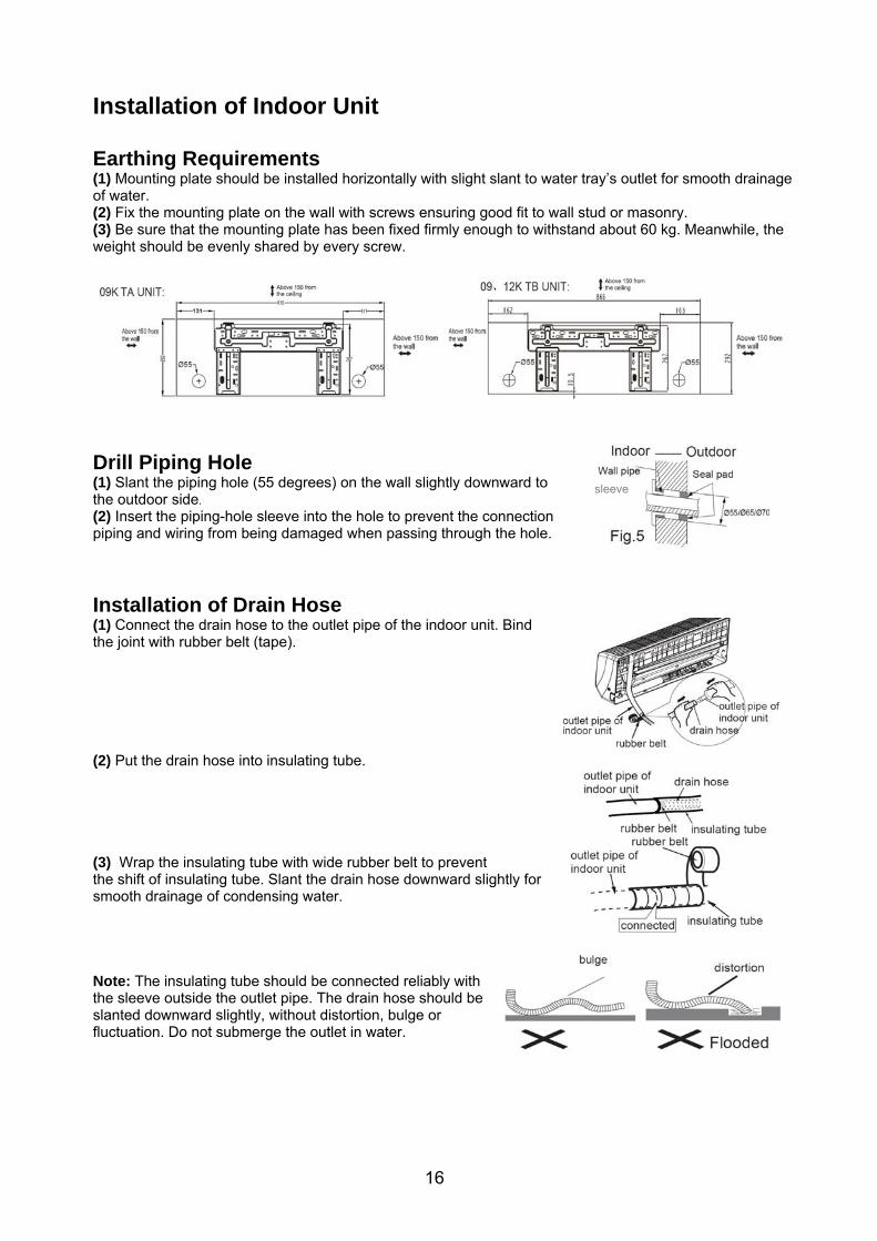
Installation of Indoor Unit Earthing Requirements (1) Mounting plate should be installed horizontally with slight slant to water tray’s outlet for smooth drainage of water. (2) Fix the mounting plate on the wall with screws ensuring good fit to wall stud or masonry. (3) Be sure that the mounting plate has been fixed firmly enough to withstand about 60 kg. Meanwhile, the weight should be evenly shared by every screw.
Drill Piping Hole (1) Slant the piping hole (55 degrees) on the wall slightly downward to the outdoor side. (2) Insert the piping-hole sleeve into the hole to prevent the connection piping and wiring from being damaged when passing through the hole.
Installation of Drain Hose (1) Connect the drain hose to the outlet pipe of the indoor unit. Bind the joint with rubber belt (tape). (2) Put the drain hose into insulating tube. (3) Wrap the insulating tube with wide rubber belt to prevent the shift of insulating tube. Slant the drain hose downward slightly for smooth drainage of condensing water. Note: The insulating tube should be connected reliably with the sleeve outside the outlet pipe. The drain hose should be slanted downward slightly, without distortion, bulge or fluctuation. Do not submerge the outlet in water.
sleeve
17
Installation of Indoor Unit con’t
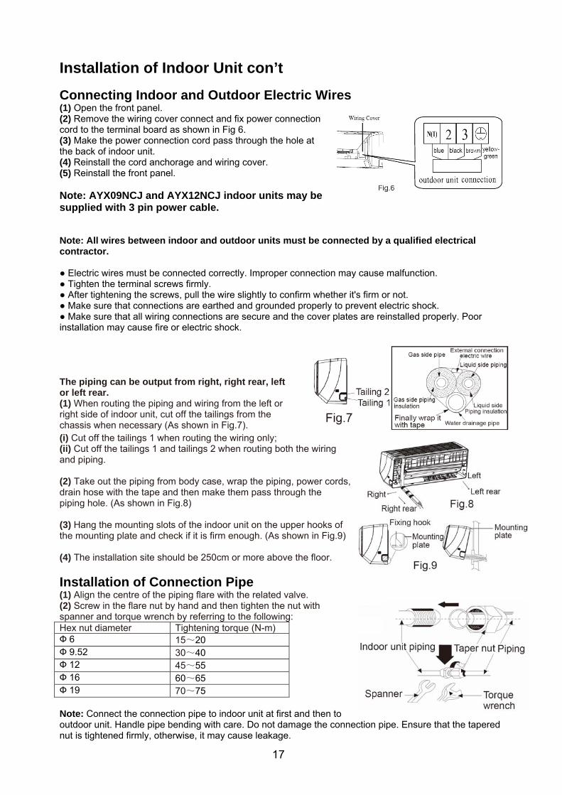
Connecting Indoor and Outdoor Electric Wires (1) Open the front panel. (2) Remove the wiring cover connect and fix power connection cord to the terminal board as shown in Fig 6. (3) Make the power connection cord pass through the hole at the back of indoor unit. (4) Reinstall the cord anchorage and wiring cover. (5) Reinstall the front panel. Note: AYX09NCJ and AYX12NCJ indoor units may be supplied with 3 pin power cable. Note: All wires between indoor and outdoor units must be connected by a qualified electrical contractor. ● Electric wires must be connected correctly. Improper connection may cause malfunction. ● Tighten the terminal screws firmly. ● After tightening the screws, pull the wire slightly to confirm whether it's firm or not. ● Make sure that connections are earthed and grounded properly to prevent electric shock. ● Make sure that all wiring connections are secure and the cover plates are reinstalled properly. Poor installation may cause fire or electric shock. The piping can be output from right, right rear, left or left rear. (1) When routing the piping and wiring from the left or right side of indoor unit, cut off the tailings from the chassis when necessary (As shown in Fig.7). (i) Cut off the tailings 1 when routing the wiring only; (ii) Cut off the tailings 1 and tailings 2 when routing both the wiring and piping. (2) Take out the piping from body case, wrap the piping, power cords, drain hose with the tape and then make them pass through the piping hole. (As shown in Fig.8) (3) Hang the mounting slots of the indoor unit on the upper hooks of the mounting plate and check if it is firm enough. (As shown in Fig.9) (4) The installation site should be 250cm or more above the floor.
Installation of Connection Pipe (1) Align the centre of the piping flare with the related valve. (2) Screw in the flare nut by hand and then tighten the nut with spanner and torque wrench by referring to the following: Hex nut diameter Tightening torque (N-m) Ф 6 15~20 Ф 9.52 30~40 Ф 12 45~55 Ф 16 60~65 Ф 19 70~75 Note: Connect the connection pipe to indoor unit at first and then to outdoor unit. Handle pipe bending with care. Do not damage the connection pipe. Ensure that the tapered nut is tightened firmly, otherwise, it may cause leakage.
18
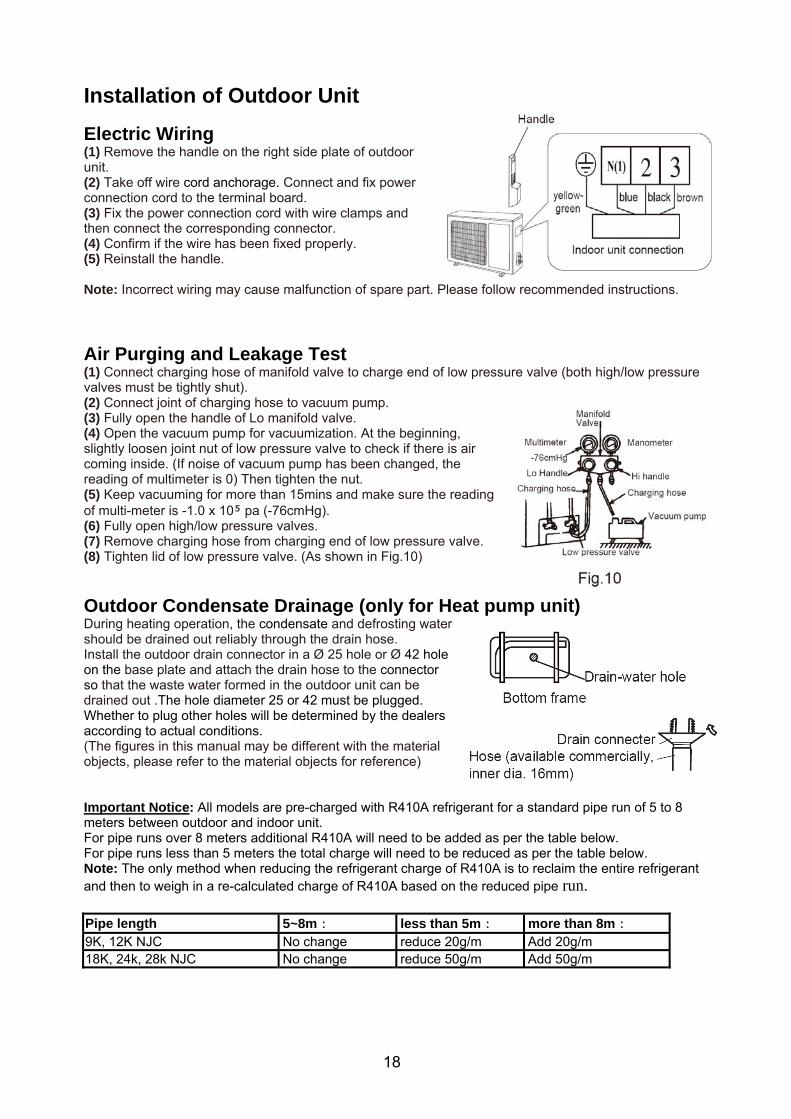
Installation of Outdoor Unit
Electric Wiring (1) Remove the handle on the right side plate of outdoor unit. (2) Take off wire cord anchorage. Connect and fix power connection cord to the terminal board. (3) Fix the power connection cord with wire clamps and then connect the corresponding connector. (4) Confirm if the wire has been fixed properly. (5) Reinstall the handle. Note: Incorrect wiring may cause malfunction of spare part. Please follow recommended instructions.
Air Purging and Leakage Test (1) Connect charging hose of manifold valve to charge end of low pressure valve (both high/low pressure valves must be tightly shut). (2) Connect joint of charging hose to vacuum pump. (3) Fully open the handle of Lo manifold valve. (4) Open the vacuum pump for vacuumization. At the beginning, slightly loosen joint nut of low pressure valve to check if there is air coming inside. (If noise of vacuum pump has been changed, the reading of multimeter is 0) Then tighten the nut. (5) Keep vacuuming for more than 15mins and make sure the reading of multi-meter is -1.0 x 10 pa (-76cmHg). (6) Fully open high/low pressure valves. (7) Remove charging hose from charging end of low pressure valve. (8) Tighten lid of low pressure valve. (As shown in Fig.10)
Outdoor Condensate Drainage (only for Heat pump unit) During heating operation, the condensate and defrosting water should be drained out reliably through the drain hose. Install the outdoor drain connector in a Ø 25 hole or Ø 42 hole on the base plate and attach the drain hose to the connector so that the waste water formed in the outdoor unit can be drained out .The hole diameter 25 or 42 must be plugged. Whether to plug other holes will be determined by the dealers according to actual conditions. (The figures in this manual may be different with the material objects, please refer to the material objects for reference) Important Notice: All models are pre-charged with R410A refrigerant for a standard pipe run of 5 to 8 meters between outdoor and indoor unit. For pipe runs over 8 meters additional R410A will need to be added as per the table below. For pipe runs less than 5 meters the total charge will need to be reduced as per the table below. Note: The only method when reducing the refrigerant charge of R410A is to reclaim the entire refrigerant and then to weigh in a re-calculated charge of R410A based on the reduced pipe run. Pipe length 5~8m: less than 5m: more than 8m: 9K, 12K NJC No change reduce 20g/m Add 20g/m 18K, 24k, 28k NJC No change reduce 50g/m Add 50g/m
19
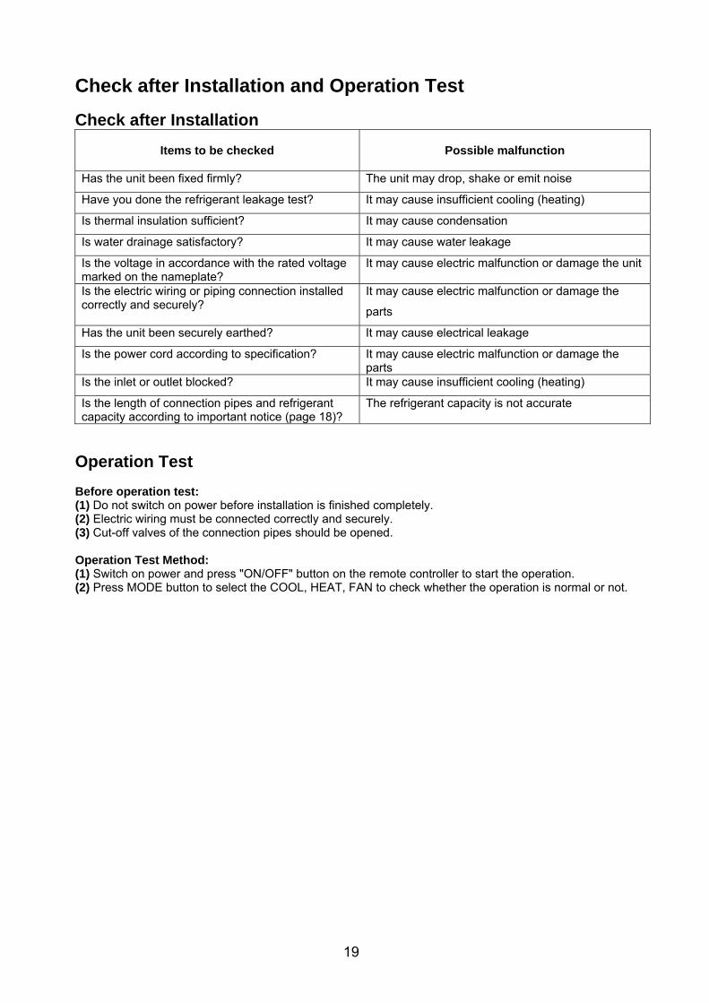
Check after Installation and Operation Test
Check after Installation
Items to be checked
Possible malfunction
Has the unit been fixed firmly? The unit may drop, shake or emit noise
Have you done the refrigerant leakage test? It may cause insufficient cooling (heating)
Is thermal insulation sufficient? It may cause condensation
Is water drainage satisfactory? It may cause water leakage
Is the voltage in accordance with the rated voltage marked on the nameplate?
It may cause electric malfunction or damage the unit
Is the electric wiring or piping connection installed correctly and securely?
It may cause electric malfunction or damage the
parts
Has the unit been securely earthed? It may cause electrical leakage
Is the power cord according to specification? It may cause electric malfunction or damage the parts
Is the inlet or outlet blocked? It may cause insufficient cooling (heating)
Is the length of connection pipes and refrigerant capacity according to important notice (page 18)?
The refrigerant capacity is not accurate
Operation Test Before operation test: (1) Do not switch on power before installation is finished completely. (2) Electric wiring must be connected correctly and securely. (3) Cut-off valves of the connection pipes should be opened. Operation Test Method: (1) Switch on power and press "ON/OFF" button on the remote controller to start the operation. (2) Press MODE button to select the COOL, HEAT, FAN to check whether the operation is normal or not.
20
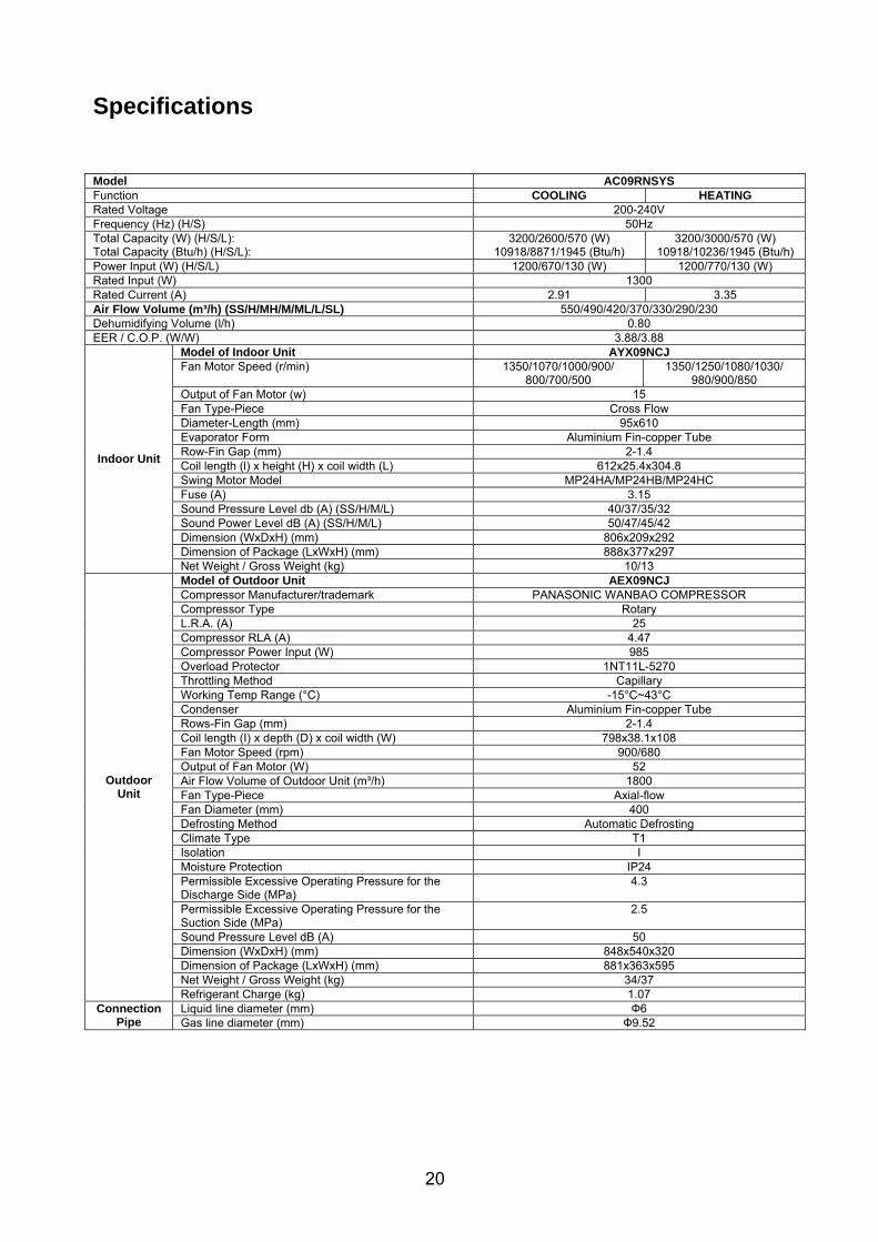
Specifications Model AC09RNSYS Function COOLING HEATING Rated Voltage 200-240V Frequency (Hz) (H/S) 50Hz Total Capacity (W) (H/S/L): Total Capacity (Btu/h) (H/S/L):
3200/2600/570 (W) 10918/8871/1945 (Btu/h)
3200/3000/570 (W) 10918/10236/1945 (Btu/h)
Power Input (W) (H/S/L) 1200/670/130 (W) 1200/770/130 (W) Rated Input (W) 1300 Rated Current (A) 2.91 3.35 Air Flow Volume (m³/h) (SS/H/MH/M/ML/L/SL) 550/490/420/370/330/290/230 Dehumidifying Volume (l/h) 0.80 EER / C.O.P. (W/W) 3.88/3.88
Model of Indoor Unit AYX09NCJ Fan Motor Speed (r/min) 1350/1070/1000/900/
800/700/500 1350/1250/1080/1030/
980/900/850 Output of Fan Motor (w) 15 Fan Type-Piece Cross Flow Diameter-Length (mm) 95x610 Evaporator Form Aluminium Fin-copper Tube Row-Fin Gap (mm) 2-1.4 Coil length (l) x height (H) x coil width (L) 612x25.4x304.8 Swing Motor Model MP24HA/MP24HB/MP24HC Fuse (A) 3.15 Sound Pressure Level db (A) (SS/H/M/L) 40/37/35/32 Sound Power Level dB (A) (SS/H/M/L) 50/47/45/42 Dimension (WxDxH) (mm) 806x209x292 Dimension of Package (LxWxH) (mm) 888x377x297
Indoor Unit
Net Weight / Gross Weight (kg) 10/13 Model of Outdoor Unit AEX09NCJ Compressor Manufacturer/trademark PANASONIC WANBAO COMPRESSOR Compressor Type Rotary L.R.A. (A) 25 Compressor RLA (A) 4.47 Compressor Power Input (W) 985 Overload Protector 1NT11L-5270 Throttling Method Capillary Working Temp Range (°C) -15°C~43°C Condenser Aluminium Fin-copper Tube Rows-Fin Gap (mm) 2-1.4 Coil length (I) x depth (D) x coil width (W) 798x38.1x108 Fan Motor Speed (rpm) 900/680 Output of Fan Motor (W) 52 Air Flow Volume of Outdoor Unit (m³/h) 1800 Fan Type-Piece Axial-flow Fan Diameter (mm) 400 Defrosting Method Automatic Defrosting Climate Type T1 Isolation I Moisture Protection IP24 Permissible Excessive Operating Pressure for the Discharge Side (MPa)
4.3
Permissible Excessive Operating Pressure for the Suction Side (MPa)
2.5
Sound Pressure Level dB (A) 50 Dimension (WxDxH) (mm) 848x540x320 Dimension of Package (LxWxH) (mm) 881x363x595 Net Weight / Gross Weight (kg) 34/37
Outdoor Unit
Refrigerant Charge (kg) 1.07 Liquid line diameter (mm) Ф6 Connection
Pipe Gas line diameter (mm) Ф9.52

21
Specifications Model AC12RNSYS Function COOLING HEATING Rated Voltage 200-240V Frequency (Hz) (H/S) 50Hz Total Capacity (W) (H/S/L): Total Capacity (Btu/h) (H/S/L):
3900/3500/660 (W) 13307/11942/2252 (Btu/h)
4300/4000/700 (W) 14672/13648/2388 (Btu/h)
Power Input (W) (H/S/L) 1100/900/165 (W) 1230/1030/175 (W) Rated Input (W) 1600 Rated Current (A) 3.91 4.48 Air Flow Volume (m³/h) (SS/H/MH/M/ML/L/SL) 750/670/610/530/460/410/380 Dehumidifying Volume (l/h) 1.40 EER / C.O.P. (W/W) 3.88/3.88
Model of Indoor Unit AYX12NCJ Fan Motor Speed (r/min) 1350/1070/1000/900/
800/700/500 1350/1150/1080/1030/
980/900/850 Output of Fan Motor (w) 15 Fan Type-Piece Cross Flow Diameter-Length (mm) 98x662 Evaporator Form Aluminium Fin-copper Tube Row-Fin Gap (mm) 2-1.5 Coil length (l) x height (H) x coil width (L) 662x25.4x304.8 Swing Motor Model MP24HA/MP24HB/MP24HC Fuse (A) 3.15 Sound Pressure Level db (A) (SS/H/M/L) 42/39/36/33 Sound Power Level dB (A) (SS/H/M/L) 52/49/46/43 Dimension (WxDxH) (mm) 866x209x292 Dimension of Package (LxWxH) (mm) 945x377x297
Indoor Unit
Net Weight / Gross Weight (kg) 11/14 Model of Outdoor Unit AEX12NCJ Compressor Manufacturer/trademark PANASONIC WANBAO COMPRESSOR Compressor Type Rotary L.R.A. (A) 25 Compressor RLA (A) 4.47 Compressor Power Input (W) 985 Overload Protector 1NT11L-5270 Throttling Method Capillary Working Temp Range (°C) -15°C~43°C Condenser Aluminium Fin-copper Tube Rows-Fin Gap (mm) 2-1.4 Coil length (I) x depth (D) x coil width (W) 704x44x559 Fan Motor Speed (rpm) 900/680 Output of Fan Motor (W) 52 Air Flow Volume of Outdoor Unit (m³/h) 2000 Fan Type-Piece Axial-flow Fan Diameter (mm) 400 Defrosting Method Automatic Defrosting Climate Type T1 Isolation I Moisture Protection IP24 Permissible Excessive Operating Pressure for the Discharge Side (MPa)
4.3
Permissible Excessive Operating Pressure for the Suction Side (MPa)
2.5
Sound Pressure Level dB (A) 52 Dimension (WxDxH) (mm) 848x592x320 Dimension of Package (LxWxH) (mm) 881x363x645 Net Weight / Gross Weight (kg) 36/39
Outdoor Unit
Refrigerant Charge (kg) 1.28 Liquid line diameter (mm) Ф6 Connection
Pipe Gas line diameter (mm) Ф9.52
22
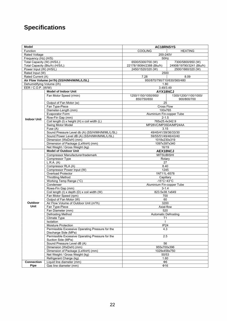
Specifications Model AC18RNSYS Function COOLING HEATING Rated Voltage 200-240V Frequency (Hz) (H/S) 50Hz Total Capacity (W) (H/S/L): Total Capacity (Btu/h) (H/S/L):
6500/5300/700 (W) 22178/18084/2388 (Btu/h)
7300/5800/950 (W) 24908/19790/3241 (Btu/h)
Power Input (W) (H/S/L) 2450/1520/320 (W) 2500/1660/320 (W) Rated Input (W) 2500 Rated Current (A) 7.28 8.09 Air Flow Volume (m³/h) (SS/H/MH/M/ML/L/SL) 950/870/790/710/630/560/480 Dehumidifying Volume (l/h) 1.80 EER / C.O.P. (W/W) 3.49/3.49
Model of Indoor Unit AYX18NCJ Fan Motor Speed (r/min) 1250/1150/1050/950/
850/750/650 1300/1200/1100/1000/
900/800/700 Output of Fan Motor (w) 25 Fan Type-Piece Cross Flow Diameter-Length (mm) 100x765 Evaporator Form Aluminium Fin-copper Tube Row-Fin Gap (mm) 2-1.5 Coil length (l) x height (H) x coil width (L) 765x25.4x342.9 Swing Motor Model MP28VC/MP35DA/MP24AA Fuse (A) 3.15 Sound Pressure Level db (A) (SS/H/MH/M/ML/L/SL) 49/45/41/39/36/33/30 Sound Power Level dB (A) (SS/H/MH/M/ML/L/SL) 59/55/51/49/46/43/40 Dimension (WxDxH) (mm) 1018x230x319 Dimension of Package (LxWxH) (mm) 1097x397x340
Indoor Unit
Net Weight / Gross Weight (kg) 16/19 Model of Outdoor Unit AEX18NCJ Compressor Manufacturer/trademark MITSUBISHI Compressor Type Rotary L.R.A. (A) 27 Compressor RLA (A) 8.40 Compressor Power Input (W) 1245 Overload Protector 1NT11L-6578 Throttling Method Capillary Working Temp Range (°C) -15°C~43°C Condenser Aluminium Fin-copper Tube Rows-Fin Gap (mm) 3-1.4 Coil length (I) x depth (D) x coil width (W) 823.5x38.1x649 Fan Motor Speed (rpm) 700 Output of Fan Motor (W) 60 Air Flow Volume of Outdoor Unit (m³/h) 3200 Fan Type-Piece Axial-flow Fan Diameter (mm) 520 Defrosting Method Automatic Defrosting Climate Type T1 Isolation I Moisture Protection IP24 Permissible Excessive Operating Pressure for the Discharge Side (MPa)
4.3
Permissible Excessive Operating Pressure for the Suction Side (MPa)
2.5
Sound Pressure Level dB (A) 56 Dimension (WxDxH) (mm) 955x700x396 Dimension of Package (LxWxH) (mm) 1029x458x750 Net Weight / Gross Weight (kg) 50/53
Outdoor Unit
Refrigerant Charge (kg) 1.60 Liquid line diameter (mm) Ф6 Connection
Pipe Gas line diameter (mm) Ф16

23
Specifications Model AC24RNSYS Function COOLING HEATING Rated Voltage 200-240V Frequency (Hz) (H/S) 50Hz Total Capacity (W) (H/S/L): Total Capacity (Btu/h) (H/S/L):
8000/7000/1200 (W) 27296/23884/4094 (Btu/h)
10000/7600/1400 (W) 34120/25931/4777 (Btu/h)
Power Input (W) (H/S/L) 3000/2000/320 (W) 3300/2170/380 (W) Rated Input (W) 3500 Rated Current (A) 8.87 9.63 Air Flow Volume (m³/h) (SS/H/MH/M/ML/L/SL) 1200/1130/1060/990/920/850/780 Dehumidifying Volume (l/h) 2.50 EER / C.O.P. (W/W) 3.50/3.50
Model of Indoor Unit AYX24NCJ Fan Motor Speed (r/min) 1400/1300/1200/1100/
1000/850/750 1350/1300/1200/1100/
1000/850/750 Output of Fan Motor (w) 60 Fan Type-Piece Cross Flow Diameter-Length (mm) 106x890 Evaporator Form Aluminium Fin-copper Tube Row-Fin Gap (mm) 2-1.5 Coil length (l) x height (H) x coil width (L) 903x25.4x381 Swing Motor Model MP35CJ/MP24HB/MP24HC Fuse (A) 3.15 Sound Pressure Level db (A) (SS/H/MH/M/ML/L/SL) 51/49/45/43/41/39/36 Sound Power Level dB (A) (SS/H/MH/M/ML/L/SL) 61/59/55/53/51/49/46 Dimension (WxDxH) (mm) 1178x264x326 Dimension of Package (LxWxH) (mm) 1256x414x364
Indoor Unit
Net Weight / Gross Weight (kg) 18/24 Model of Outdoor Unit AEX24NCJ Compressor Manufacturer/trademark MITSUBISHI Compressor Type Rotary L.R.A. (A) 45 Compressor RLA (A) 10.63 Compressor Power Input (W) 2200 Overload Protector CS-7C-1595 Throttling Method Capillary Working Temp Range (°C) -15°C~43°C Condenser Aluminium Fin-copper Tube Rows-Fin Gap (mm) 3-1.5 Coil length (I) x depth (D) x coil width (W) 960x57.15x748 Fan Motor Speed (rpm) 780 Output of Fan Motor (W) 90 Air Flow Volume of Outdoor Unit (m³/h) 4000 Fan Type-Piece Axial-flow Fan Diameter (mm) 552 Defrosting Method Automatic Defrosting Climate Type T1 Isolation I Moisture Protection IP24 Permissible Excessive Operating Pressure for the Discharge Side (MPa)
4.3
Permissible Excessive Operating Pressure for the Suction Side (MPa)
2.5
Sound Pressure Level dB (A) 56 Dimension (WxDxH) (mm) 980x427x790 Dimension of Package (LxWxH) (mm) 1083x488x855 Net Weight / Gross Weight (kg) 68/74
Outdoor Unit
Refrigerant Charge (kg) 2.30 Liquid line diameter (mm) Ф6 Connection
Pipe Gas line diameter (mm) Ф16

24
Specifications Model AC28RNSYS Function COOLING HEATING Rated Voltage 200-240V Frequency (Hz) (H/S) 50Hz Total Capacity (W) (H/S/L): Total Capacity (Btu/h) (H/S/L):
9000/8000/1000 (W) 30708/27296/3412 (Btu/h)
11000/8400/1300 (W) 37532/28661/4436 (Btu/h)
Power Input (W) (H/S/L) 2900/2390/300 (W) 4000/2510/350 (W) Rated Input (W) 4200 Rated Current (A) 10.60 11.14 Air Flow Volume (m³/h) (SS/H/MH/M/ML/L/SL) 1200/1130/1060/990/920/850/780 Dehumidifying Volume (l/h) 2.70 EER / C.O.P. (W/W) 3.35/3.35
Model of Indoor Unit AYX28NCJ Fan Motor Speed (r/min) 1400/1300/1200/1100/
1000/850/750 1350/1300/1200/1100/
1000/850/750 Output of Fan Motor (w) 70 Fan Type-Piece Cross Flow Diameter-Length (mm) 106x890 Evaporator Form Aluminium Fin-copper Tube Row-Fin Gap (mm) 2-1.5 Coil length (l) x height (H) x coil width (L) 903x25.4x381 Swing Motor Model MP35CJ/MP24HB/MP24HC Fuse (A) 3.15 Sound Pressure Level db (A) (SS/H/MH/M/ML/L/SL) 51/49/45/43/41/39/36 Sound Power Level dB (A) (SS/H/MH/M/ML/L/SL) 61/59/55/53/51/49/46 Dimension (WxDxH) (mm) 1178x264x326 Dimension of Package (LxWxH) (mm) 1256x414x364
Indoor Unit
Net Weight / Gross Weight (kg) 18/24 Model of Outdoor Unit AEX28NCJ Compressor Manufacturer/trademark MITSUBISHI Compressor Type Rotary L.R.A. (A) 40 Compressor RLA (A) 12 Compressor Power Input (W) 2450 Overload Protector 1NT11L-6233 Throttling Method Capillary Working Temp Range (°C) -15°C~43°C Condenser Aluminium Fin-copper Tube Rows-Fin Gap (mm) 3-1.5 Coil length (I) x depth (D) x coil width (W) 960x57.15x748 Fan Motor Speed (rpm) 780 Output of Fan Motor (W) 90 Air Flow Volume of Outdoor Unit (m³/h) 4000 Fan Type-Piece Axial-flow Fan Diameter (mm) 552 Defrosting Method Automatic Defrosting Climate Type T1 Isolation I Moisture Protection IP24 Permissible Excessive Operating Pressure for the Discharge Side (MPa)
4.3
Permissible Excessive Operating Pressure for the Suction Side (MPa)
2.5
Sound Pressure Level dB (A) 58 Dimension (WxDxH) (mm) 980x427x790 Dimension of Package (LxWxH) (mm) 1083x488x855 Net Weight / Gross Weight (kg) 69/75
Outdoor Unit
Refrigerant Charge (kg) 2.40 Liquid line diameter (mm) Ф6 Connection
Pipe Gas line diameter (mm) Ф16

25
26
27

28
SHARP CORPORATION OF AUSTRALIA PTY. LTD. A.B.N. 40 003 039 405
1 HUNTINGWOOD DRIVE, HUNTINGWOOD, N.S.W. 2148 P.O. 6827, BLACKTOWN, N.S.W. 2148
www.sharp.net.au
SHARP CORPORATION OF NEW ZEALAND LIMITED 59 HUGO JOHNSTON DRIVE, PENROSE, AUCKLAND
www.sharp.net.nz