Embed Size (px)
Citation preview
SHD-U Series
Hopper Dryer
Date: Apr, 2019
Version: Ver.D (English)

3(49)
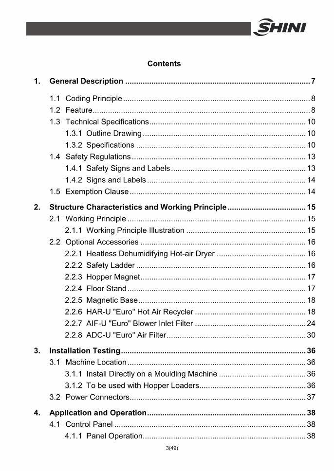
Contents
1. General Description ..................................................................................... 7
1.1 Coding Principle ...................................................................................... 8
1.2 Feature .................................................................................................... 8
1.3 Technical Specifications ........................................................................ 10
1.3.1 Outline Drawing ........................................................................... 10
1.3.2 Specifications .............................................................................. 10
1.4 Safety Regulations ................................................................................ 13
1.4.1 Safety Signs and Labels .............................................................. 13
1.4.2 Signs and Labels ......................................................................... 14
1.5 Exemption Clause ................................................................................. 14
2. Structure Characteristics and Working Principle .................................... 15
2.1 Working Principle .................................................................................. 15
2.1.1 Working Principle Illustration ....................................................... 15
2.2 Optional Accessories ............................................................................ 16
2.2.1 Heatless Dehumidifying Hot-air Dryer ......................................... 16
2.2.2 Safety Ladder .............................................................................. 16
2.2.3 Hopper Magnet ............................................................................ 17
2.2.4 Floor Stand .................................................................................. 17
2.2.5 Magnetic Base ............................................................................. 18
2.2.6 HAR-U "Euro" Hot Air Recycler ................................................... 18
2.2.7 AIF-U "Euro" Blower Inlet Filter ................................................... 24
2.2.8 ADC-U "Euro" Air Filter ................................................................ 30
3. Installation Testing ..................................................................................... 36
3.1 Machine Location .................................................................................. 36
3.1.1 Install Directly on a Moulding Machine ........................................ 36
3.1.2 To be used with Hopper Loaders ................................................. 36
3.2 Power Connectors ................................................................................. 37
4. Application and Operation ......................................................................... 38
4.1 Control Panel ........................................................................................ 38
4.1.1 Panel Operation ........................................................................... 38
4(49)
4.1.2 Temperature Setting .................................................................... 38
4.1.3 Temperature Lock ....................................................................... 38
4.1.4 PID Setting .................................................................................. 39
4.1.5 Intermittent Operation Setting ...................................................... 40
4.1.6 One-week Timing Setting ............................................................ 40
4.1.7 Communication Setting (optional functions) ................................ 40
4.1.8 Operation Flow ............................................................................ 42
4.1.9 Wrong Codes Remark ................................................................. 43
5. Trouble-shooting ........................................................................................ 44
6. Maintenance and Repair ............................................................................ 45
6.1 Blower ................................................................................................... 48
6.2 Maintenance Schedule .......................................................................... 48
6.2.1 General Machine Information ...................................................... 48
6.2.2 Installation & Inspection ............................................................... 48
6.2.3 Daily Checking ............................................................................. 48
6.2.4 Weekly Checking ......................................................................... 48
6.2.5 Monthly Checking ........................................................................ 48
6.2.6 Half-yearly Checking ................................................................... 49
Table Index
Table 1-1: Specifications 1 ............................................................................... 10
Table 1-2: Specifications 2 ............................................................................... 11
Table 1-3: Specifications 3 ............................................................................... 11
Table 1-4: Specifications 4 ............................................................................... 11
Table 2-1: HAR-U Specifications ...................................................................... 19
Table 2-2: HAR-U Out Dimensions ................................................................... 20
Table 2-3: AIF-U Specifications ........................................................................ 25
Table 2-4: AIF-U Out Dimensions ..................................................................... 26
Table 2-5: ADC-U Specifications ...................................................................... 31
Table 2-6: ADC-U Out Dimensions ................................................................... 32
5(49)
Picture Index
Picture 1-1: Outline Drawing ............................................................................. 10
Picture 2-1: Working Principle Illustration ......................................................... 15
Picture 2-2: SHD-U-HD Working Principle ........................................................ 16
Picture 2-3: Safety Ladder ................................................................................ 16
Picture 2-4: Hopper Magnet .............................................................................. 17
Picture 2-5: Floor Stand .................................................................................... 17
Picture 2-6: Magnetic Base ............................................................................... 18
Picture 2-7: "Euro" Hot Air Recycler ................................................................. 19
Picture 2-8: Technical Specifications ................................................................ 20
Picture 2-9: Working Principle .......................................................................... 21
Picture 2-10: Installation of Filter and Dust Collecting Barrel ............................ 22
Picture 2-11: Installation of the Assembly Parts for the Cylinder Filter ............. 22
Picture 2-12: Install "Euro" Hot Air Recycler on Hopper Dryer .......................... 23
Picture 2-13: Installation of the Flange of Blower Inlet ...................................... 23
Picture 2-14: Connection of Air Pipe ................................................................. 23
Picture 2-15: Clean up the "Euro" Hot Air Recycler .......................................... 24
Picture 2-16: "Euro" Blower Inlet Filter .............................................................. 24
Picture 2-17: Technical Specifications .............................................................. 26
Picture 2-18: Working Principle ........................................................................ 27
Picture 2-19: Installation of Filter and Dust Collecting Barrel ............................ 28
Picture 2-20: Installation of the Assembly Parts for the Cylinder Filter ............. 28
Picture 2-21: Install "Euro" Hot Air Recycler on Hopper Dryer .......................... 29
Picture 2-22: Installation of the Flange of Blower Inlet ...................................... 29
Picture 2-23: Connection of Air Pipe ................................................................. 29
Picture 2-24: Clean up the "Euro" Hot Air Recycler .......................................... 30
Picture 2-25: "Euro" Air Filter ............................................................................ 30
Picture 2-26: ADC-U Technical Specifications .................................................. 31
Picture 2-27: Installation of Filter and Dust Collecting Barrel ............................ 33
Picture 2-28: Installation of the Assembly Parts for the Cylinder Filter ............. 33
Picture 2-29: Install "Euro" Hot Air Recycler on Hopper Dryer .......................... 34
Picture 2-30: Installation of the Flange of Blower Inlet ...................................... 34
Picture 2-31: Connection of Air Pipe ................................................................. 34
6(49)
Picture 2-32: Clean up the "Euro" Hot Air Recycler .......................................... 35
Picture 3-1: Install Directly on a Moulding Machine .......................................... 36
Picture 3-2: To be used with Hopper Loaders .................................................. 36
7(49)
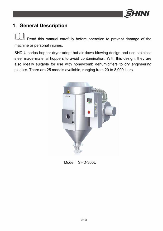
1. General Description
Read this manual carefully before operation to prevent damage of the
machine or personal injuries.
SHD-U series hopper dryer adopt hot air down-blowing design and use stainless steel made material hoppers to avoid contamination. With this design, they are also ideally suitable for use with honeycomb dehumidifiers to dry engineering plastics. There are 25 models available, ranging from 20 to 8,000 liters.
Model:SHD-300U
8(49)
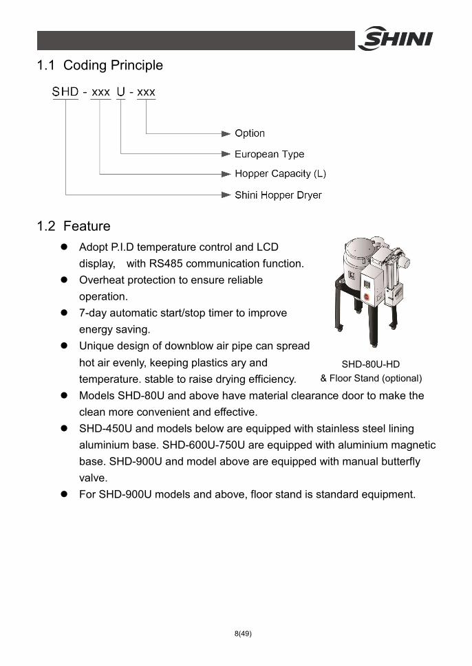
1.1 Coding Principle
1.2 Feature l Adopt P.I.D temperature control and LCD
display, with RS485 communication function. l Overheat protection to ensure reliable
operation. l 7-day automatic start/stop timer to improve
energy saving. l Unique design of downblow air pipe can spread
hot air evenly, keeping plastics ary and temperature. stable to raise drying efficiency.
l Models SHD-80U and above have material clearance door to make the clean more convenient and effective.
l SHD-450U and models below are equipped with stainless steel lining aluminium base. SHD-600U-750U are equipped with aluminium magnetic base. SHD-900U and model above are equipped with manual butterfly valve.
l For SHD-900U models and above, floor stand is standard equipment.
SHD-80U-HD & Floor Stand (optional)
9(49)
All service work should be carried out by a person with technical training or corresponding professional experience. The manual contains instructions for both handling and servicing. Chapter 6, which contains service instructions intended for service engineers. Other chapters contain instructions for the daily operator.
Any modifications of the machine must be approved by SHINI in order to avoid personal injury and damage to machine. We shall not be liable for any damage caused by unauthorized change of the machine.
Our company provides excellent after-sales service. Should you have any problem during using the machine, please contact the company or the local vendor.
Headquarter and Taipei factory:
Tel: (886) 2 2680 9119
Shini Plastics Technologies (Dongguan), Inc:
Tel: (86) 769 8111 6600
Shini Plastics Technologies India Pvt.Ltd.:
Tel: (91) 250 3021 166
10(49)
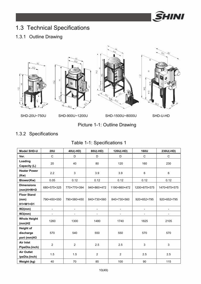
1.3 Technical Specifications 1.3.1 Outline Drawing
SHD-20U~750U SHD-900U~1200U SHD-1500U~8000U SHD-U-HD
Picture 1-1: Outline Drawing
1.3.2 Specifications
Table 1-1: Specifications 1 Model SHD-U 20U 40U(-HD) 80U(-HD) 120U(-HD) 160U 230U(-HD)
Ver. C D D D C C Loading Capacity (L)
20 40 80 120 160 230
Heater Power (Kw)
2.2 3 3.9 3.9 6 6
Blower(Kw) 0.05 0.12 0.12 0.12 0.12 0.12 Dimensions (mm)H×W×D
680×575×325 770×770×394 940×860×472 1190×860×472 1200×875×575 1470×875×575
Floor Stand (mm) H1×W1×D1
790×450×550 790×580×450 840×730×560 840×730×560 920×652×795 920×652×795
W2(mm) - - - - - - W3(mm) - - - - - - Whole Height (mm)H2
1260 1300 1480 1740 1825 2105
Height of discharge port (mm)H3
570 540 550 550 570 570
Air Inlet PipeDia.(inch)
2 2 2.5 2.5 3 3
Air Outlet ipeDia.(inch)
1.5 1.5 2 2 2.5 2.5
Weight (kg) 40 70 85 100 90 115
11(49)
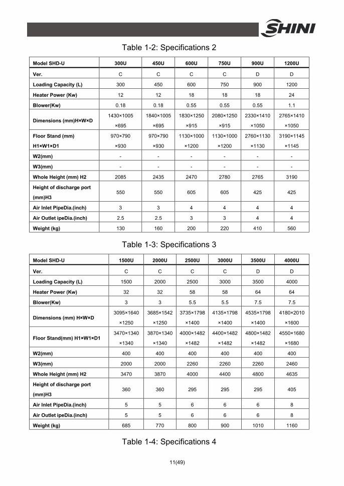
Table 1-2: Specifications 2
Model SHD-U 300U 450U 600U 750U 900U 1200U
Ver. C C C C D D
Loading Capacity (L) 300 450 600 750 900 1200
Heater Power (Kw) 12 12 18 18 18 24
Blower(Kw) 0.18 0.18 0.55 0.55 0.55 1.1
Dimensions (mm)H×W×D 1430×1005
×695
1840×1005
×695
1830×1250
×915
2080×1250
×915
2330×1410
×1050
2765×1410
×1050
Floor Stand (mm)
H1×W1×D1
970×790
×930
970×790
×930
1130×1000
×1200
1130×1000
×1200
2760×1130
×1130
3190×1145
×1145
W2(mm) - - - - - -
W3(mm) - - - - - -
Whole Height (mm) H2 2085 2435 2470 2780 2765 3190
Height of discharge port
(mm)H3 550 550 605 605 425 425
Air Inlet PipeDia.(inch) 3 3 4 4 4 4
Air Outlet ipeDia.(inch) 2.5 2.5 3 3 4 4
Weight (kg) 130 160 200 220 410 560
Table 1-3: Specifications 3
Model SHD-U 1500U 2000U 2500U 3000U 3500U 4000U
Ver. C C C C D D
Loading Capacity (L) 1500 2000 2500 3000 3500 4000
Heater Power (Kw) 32 32 58 58 64 64
Blower(Kw) 3 3 5.5 5.5 7.5 7.5
Dimensions (mm) H×W×D 3095×1640
×1250
3685×1542
×1250
3735×1798
×1400
4135×1798
×1400
4535×1798
×1400
4180×2010
×1600
Floor Stand(mm) H1×W1×D1 3470×1340
×1340
3870×1340
×1340
4000×1482
×1482
4400×1482
×1482
4800×1482
×1482
4550×1680
×1680
W2(mm) 400 400 400 400 400 400
W3(mm) 2000 2000 2260 2260 2260 2460
Whole Height (mm) H2 3470 3870 4000 4400 4800 4635
Height of discharge port
(mm)H3 360 360 295 295 295 405
Air Inlet PipeDia.(inch) 5 5 6 6 6 8
Air Outlet ipeDia.(inch) 5 5 6 6 6 8
Weight (kg) 685 770 800 900 1010 1160
Table 1-4: Specifications 4
12(49)
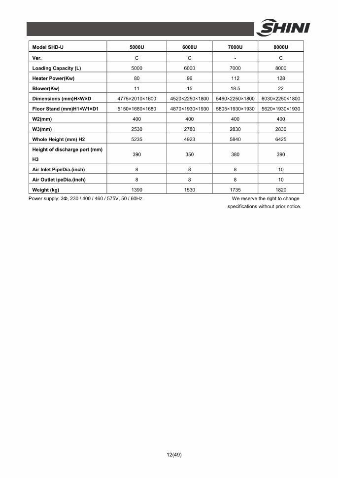
Model SHD-U 5000U 6000U 7000U 8000U
Ver. C C - C
Loading Capacity (L) 5000 6000 7000 8000
Heater Power(Kw) 80 96 112 128
Blower(Kw) 11 15 18.5 22
Dimensions (mm)H×W×D 4775×2010×1600 4520×2250×1800 5460×2250×1800 6030×2250×1800
Floor Stand (mm)H1×W1×D1 5150×1680×1680 4870×1930×1930 5805×1930×1930 5620×1930×1930
W2(mm) 400 400 400 400
W3(mm) 2530 2780 2830 2830
Whole Height (mm) H2 5235 4923 5840 6425
Height of discharge port (mm)
H3 390 350 380 390
Air Inlet PipeDia.(inch) 8 8 8 10
Air Outlet ipeDia.(inch) 8 8 8 10
Weight (kg) 1390 1530 1735 1820
Power supply: 3Φ, 230 / 400 / 460 / 575V, 50 / 60Hz. We reserve the right to change specifications without prior notice.
13(49)
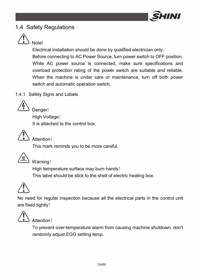
1.4 Safety Regulations
Note! Electrical installation should be done by qualified electrician only. Before connecting to AC Power Source, turn power switch to OFF position. While AC power source is connected, make sure specifications and overload protection rating of the power switch are suitable and reliable. When the machine is under care or maintenance, turn off both power switch and automatic operation switch.
1.4.1 Safety Signs and Labels
Danger! High Voltage! It is attached to the control box.
Attention! This mark reminds you to be more careful.
Warning! High temperature surface may burn hands! This label should be stick to the shell of electric heating box.
No need for regular inspection because all the electrical parts in the control unit are fixed tightly!
Attention! To prevent over-temperature alarm from causing machine shutdown, don't randomly adjust EGO setting temp.
14(49)
Attention! For test of SHD-2500U and above models, connect all hot air pipes to avoid damage of the blower.
Attention! For test of SHD-2500U and above models, half-open the air-in valve of the blower to avoid damage of it.
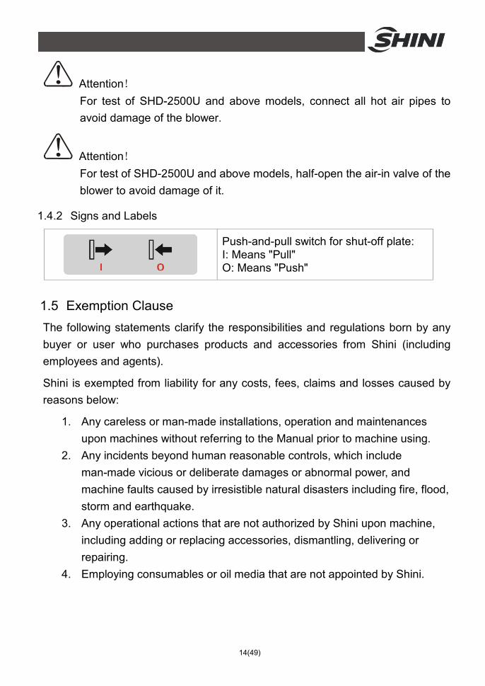
1.4.2 Signs and Labels
Push-and-pull switch for shut-off plate: I: Means "Pull" O: Means "Push"
1.5 Exemption Clause The following statements clarify the responsibilities and regulations born by any buyer or user who purchases products and accessories from Shini (including employees and agents).
Shini is exempted from liability for any costs, fees, claims and losses caused by reasons below:
1. Any careless or man-made installations, operation and maintenances upon machines without referring to the Manual prior to machine using.
2. Any incidents beyond human reasonable controls, which include man-made vicious or deliberate damages or abnormal power, and machine faults caused by irresistible natural disasters including fire, flood, storm and earthquake.
3. Any operational actions that are not authorized by Shini upon machine, including adding or replacing accessories, dismantling, delivering or repairing.
4. Employing consumables or oil media that are not appointed by Shini.
15(49)
2. Structure Characteristics and Working Principle 2.1 Working Principle In the drying process, hot air with constant temperature is blowed by a blower into a two-layer insulated hopper to dry the materials. Moisture will be separated out and taken away by hot air, thus to gain a satisfied drying effect.
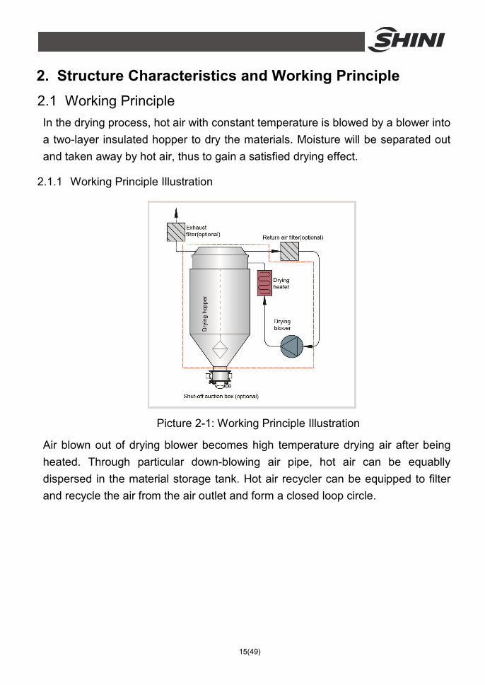
2.1.1 Working Principle Illustration
Picture 2-1: Working Principle Illustration
Air blown out of drying blower becomes high temperature drying air after being heated. Through particular down-blowing air pipe, hot air can be equablly dispersed in the material storage tank. Hot air recycler can be equipped to filter and recycle the air from the air outlet and form a closed loop circle.
16(49)
2.2 Optional Accessories 2.2.1 Heatless Dehumidifying Hot-air Dryer
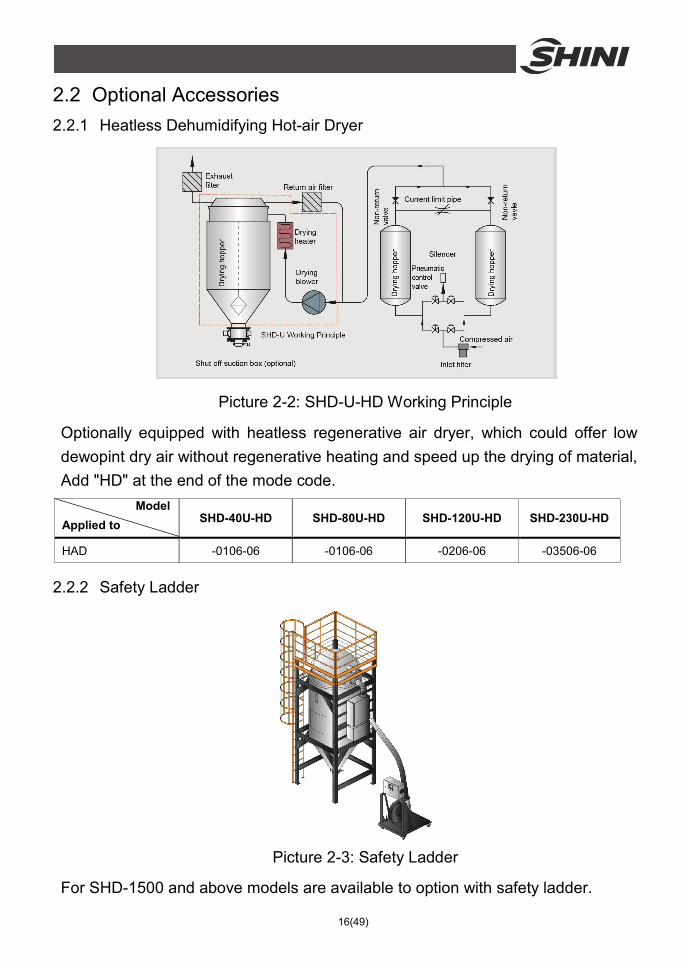
Picture 2-2: SHD-U-HD Working Principle
Optionally equipped with heatless regenerative air dryer, which could offer low dewopint dry air without regenerative heating and speed up the drying of material, Add "HD" at the end of the mode code. Model Applied to SHD-40U-HD SHD-80U-HD SHD-120U-HD SHD-230U-HD
HAD -0106-06 -0106-06 -0206-06 -03506-06
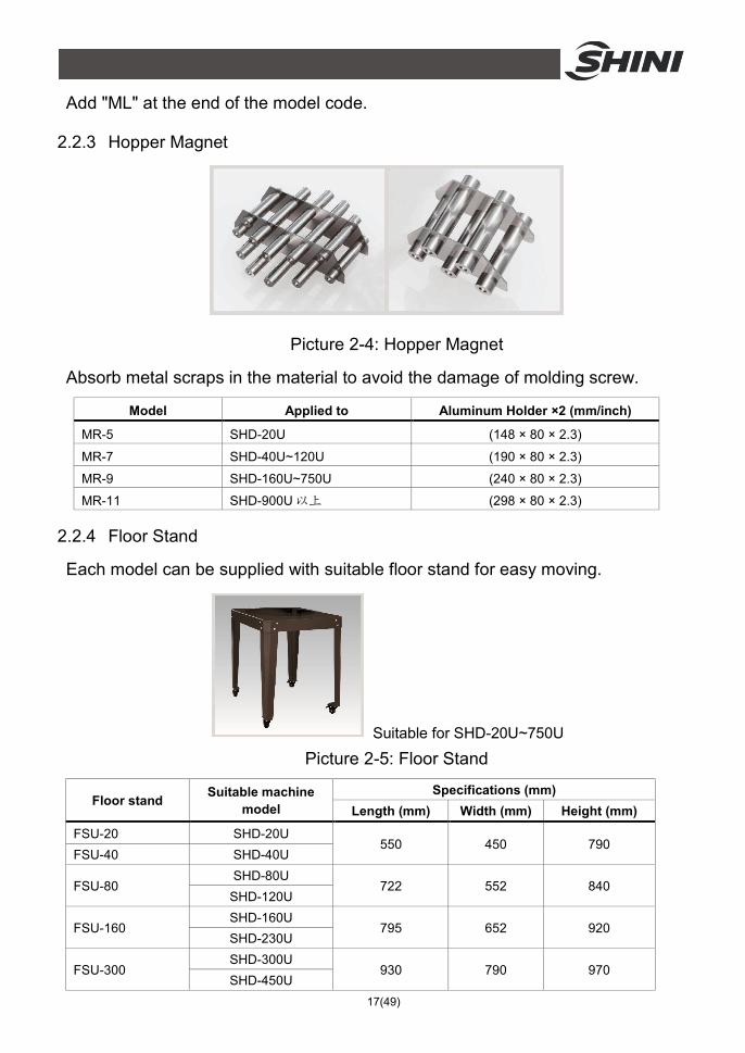
2.2.2 Safety Ladder
Picture 2-3: Safety Ladder
For SHD-1500 and above models are available to option with safety ladder.
17(49)
Add "ML" at the end of the model code.
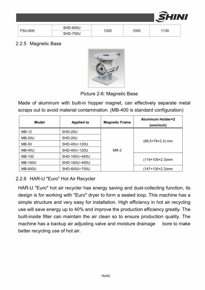
2.2.3 Hopper Magnet
Picture 2-4: Hopper Magnet
Absorb metal scraps in the material to avoid the damage of molding screw.
Model Applied to Aluminum Holder ×2 (mm/inch)
MR-5 SHD-20U (148 × 80 × 2.3)
MR-7 SHD-40U~120U (190 × 80 × 2.3)
MR-9 SHD-160U~750U (240 × 80 × 2.3)
MR-11 SHD-900U以上 (298 × 80 × 2.3)
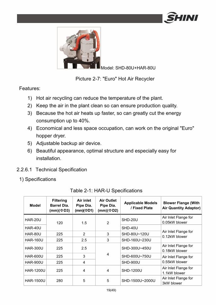
2.2.4 Floor Stand
Each model can be supplied with suitable floor stand for easy moving.
Suitable for SHD-20U~750U Picture 2-5: Floor Stand
Floor stand Suitable machine model
Specifications (mm) Length (mm) Width (mm) Height (mm)
FSU-20 SHD-20U 550 450 790
FSU-40 SHD-40U
FSU-80 SHD-80U
722 552 840 SHD-120U
FSU-160 SHD-160U
795 652 920 SHD-230U
FSU-300 SHD-300U
930 790 970 SHD-450U
18(49)
FSU-600 SHD-600U
1200 1000 1130 SHD-750U
2.2.5 Magnetic Base
Picture 2-6: Magnetic Base
Made of aluminum with built-in hopper magnet, can effectively separate metal scraps out to avoid material contamination. (MB-400 is standard configuration)
Model Applied to Magnetic Frame Aluminum Holder×2
(mm/inch)
MB-12 SHD-20U
MR-3
(88.5×78×2.3) mm MB-20U SHD-20U
MB-50 SHD-40U~120U
MB-40U SHD-40U~120U
MB-100 SHD-160U~450U (119×105×2.3)mm
MB-160U SHD-160U~450U
MB-600U SHD-600U~750U (147×130×2.3)mm
2.2.6 HAR-U "Euro" Hot Air Recycler
HAR-U "Euro" hot air recycler has energy saving and dust-collecting function, its design is for working with "Euro" dryer to form a sealed loop. This machine has a simple structure and very easy for installation. High efficiency in hot air recycling use will save energy up to 40% and improve the production efficiency greatly. The built-inside filter can maintain the air clean so to ensure production quality. The machine has a backup air adjusting valve and moisture drainage bore to make better recycling use of hot air.
19(49)
Model: SHD-80U+HAR-80U
Picture 2-7: "Euro" Hot Air Recycler
Features:
1) Hot air recycling can reduce the temperature of the plant. 2) Keep the air in the plant clean so can ensure production quality. 3) Because the hot air heats up faster, so can greatly cut the energy
consumption up to 40%. 4) Economical and less space occupation, can work on the original "Euro"
hopper dryer. 5) Adjustable backup air device. 6) Beautiful appearance, optimal structure and especially easy for
installation.
2.2.6.1 Technical Specification
1) Specifications
Table 2-1: HAR-U Specifications
Model Filtering
Barrel Dia. (mm)(ФD3)
Air inlet Pipe Dia.
(mm)(ФD1)
Air Outlet Pipe Dia.
(mm)(ФD2)
Applicable Models / Fixed Plate
Blower Flange (With Air Quantity Adaptor)
HAR-20U 120 1.5 2
SHD-20U Air lnlet Flange for 0.05kW blower
HAR-40U SHD-40U Air lnlet Flange for 0.12kW blower
HAR-80U 225 2 3 SHD-80U~120U HAR-160U 225 2.5 3 SHD-160U~230U
HAR-300U 225 2.5 4
SHD-300U~450U Air lnlet Flange for 0.18kW blower
HAR-600U 225 3 SHD-600U~750U Air lnlet Flange for 0.55kW blower HAR-900U 225 4 SHD-900U
HAR-1200U 225 4 4 SHD-1200U Air lnlet Flange for 1.1kW blower
HAR-1500U 280 5 5 SHD-1500U~2000U Air lnlet Flange for 3kW blower
20(49)
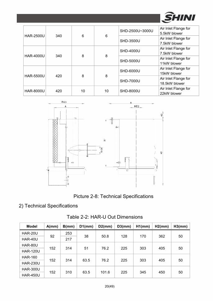
HAR-2500U 340 6 6 SHD-2500U~3000U
Air lnlet Flange for 5.5kW blower
SHD-3500U Air lnlet Flange for 7.5kW blower
HAR-4000U 340 8 8 SHD-4000U
Air lnlet Flange for 7.5kW blower
SHD-5000U Air lnlet Flange for 11kW blower
HAR-5500U 420 8 8 SHD-6000U
Air lnlet Flange for 15kW blower
SHD-7000U Air lnlet Flange for 18.5kW blower
HAR-8000U 420 10 10 SHD-8000U Air lnlet Flange for 22kW blower
Picture 2-8: Technical Specifications
2) Technical Specifications
Table 2-2: HAR-U Out Dimensions
Model A(mm) B(mm) D1(mm) D2(mm) D3(mm) H1(mm) H2(mm) H3(mm)
HAR-20U 92
253 38 50.8 128 170 362 50
HAR-40U 217 HAR-80U
152 314 51 76.2 225 303 405 50 HAR-120U HAR-160
152 314 63.5 76.2 225 303 405 50 HAR-230U HAR-300U
152 310 63.5 101.6 225 345 450 50 HAR-450U
21(49)
HAR-600U 152 322 76.2 101.6 225 345 450 50
HAR-750U HAR-900U
152 322 101.6 101.6 225 345 450 50 HAR-1200U HAR-2500U 200 490 152.4 152.4 340 605 818 240
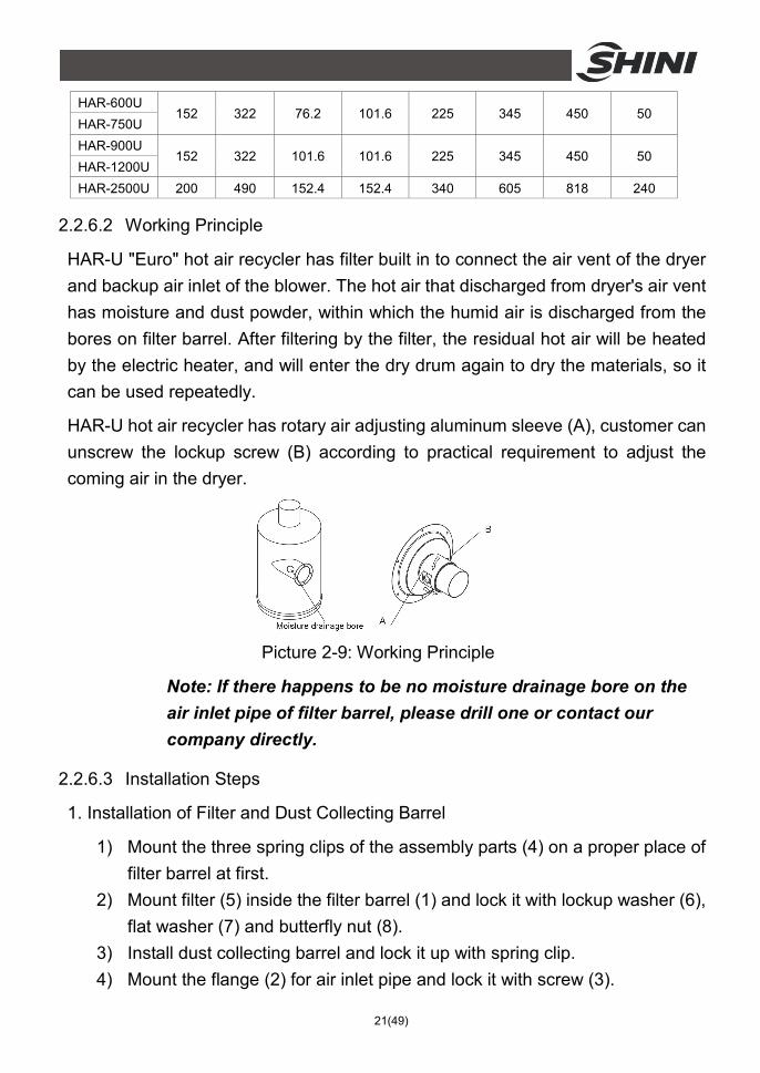
2.2.6.2 Working Principle
HAR-U "Euro" hot air recycler has filter built in to connect the air vent of the dryer and backup air inlet of the blower. The hot air that discharged from dryer's air vent has moisture and dust powder, within which the humid air is discharged from the bores on filter barrel. After filtering by the filter, the residual hot air will be heated by the electric heater, and will enter the dry drum again to dry the materials, so it can be used repeatedly.
HAR-U hot air recycler has rotary air adjusting aluminum sleeve (A), customer can unscrew the lockup screw (B) according to practical requirement to adjust the coming air in the dryer.
Picture 2-9: Working Principle
Note: If there happens to be no moisture drainage bore on the air inlet pipe of filter barrel, please drill one or contact our company directly.
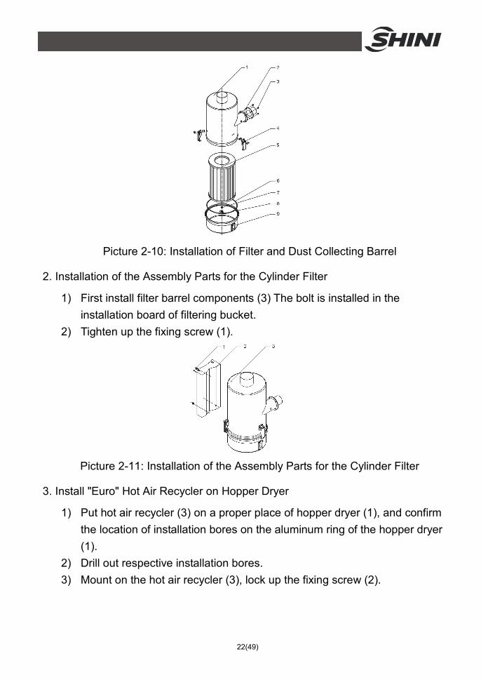
2.2.6.3 Installation Steps
1. Installation of Filter and Dust Collecting Barrel
1) Mount the three spring clips of the assembly parts (4) on a proper place of filter barrel at first.
2) Mount filter (5) inside the filter barrel (1) and lock it with lockup washer (6), flat washer (7) and butterfly nut (8).
3) Install dust collecting barrel and lock it up with spring clip. 4) Mount the flange (2) for air inlet pipe and lock it with screw (3).
22(49)
Picture 2-10: Installation of Filter and Dust Collecting Barrel
2. Installation of the Assembly Parts for the Cylinder Filter
1) First install filter barrel components (3) The bolt is installed in the installation board of filtering bucket.
2) Tighten up the fixing screw (1).
Picture 2-11: Installation of the Assembly Parts for the Cylinder Filter
3. Install "Euro" Hot Air Recycler on Hopper Dryer
1) Put hot air recycler (3) on a proper place of hopper dryer (1), and confirm the location of installation bores on the aluminum ring of the hopper dryer (1).
2) Drill out respective installation bores. 3) Mount on the hot air recycler (3), lock up the fixing screw (2).
23(49)
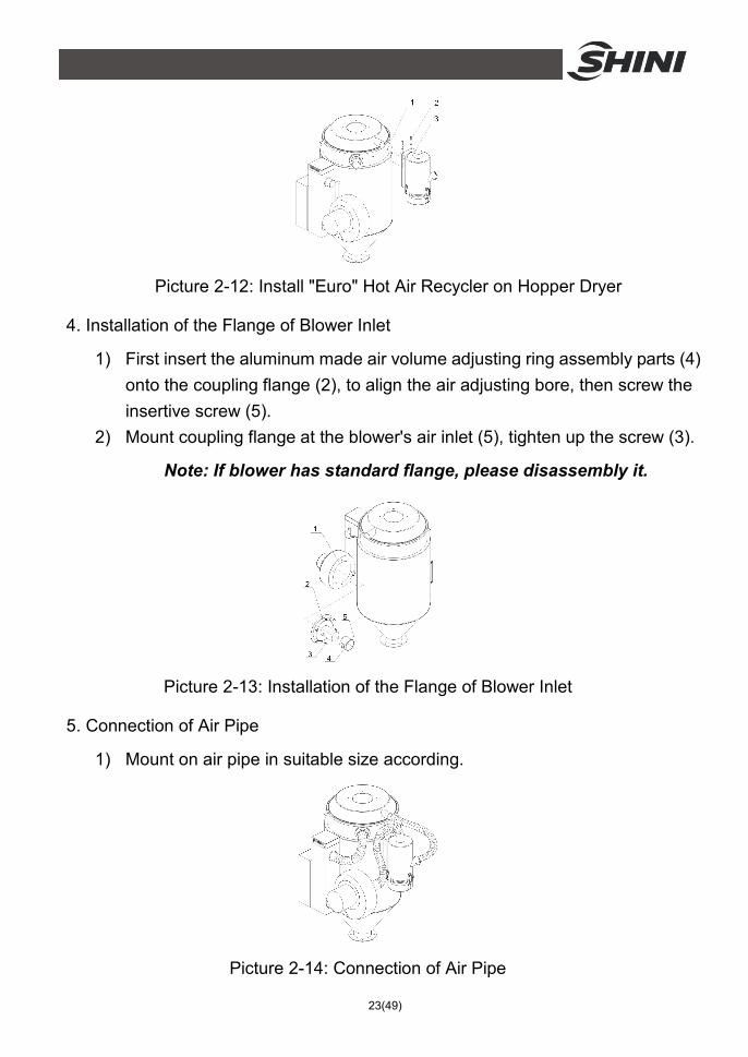
Picture 2-12: Install "Euro" Hot Air Recycler on Hopper Dryer
4. Installation of the Flange of Blower Inlet
1) First insert the aluminum made air volume adjusting ring assembly parts (4) onto the coupling flange (2), to align the air adjusting bore, then screw the insertive screw (5).
2) Mount coupling flange at the blower's air inlet (5), tighten up the screw (3).
Note: If blower has standard flange, please disassembly it.
Picture 2-13: Installation of the Flange of Blower Inlet
5. Connection of Air Pipe
1) Mount on air pipe in suitable size according.
Picture 2-14: Connection of Air Pipe
24(49)
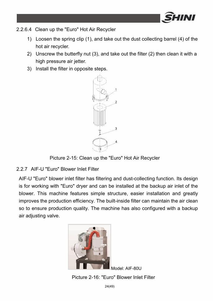
2.2.6.4 Clean up the "Euro" Hot Air Recycler
1) Loosen the spring clip (1), and take out the dust collecting barrel (4) of the hot air recycler.
2) Unscrew the butterfly nut (3), and take out the filter (2) then clean it with a high pressure air jetter.
3) Install the filter in opposite steps.
Picture 2-15: Clean up the "Euro" Hot Air Recycler
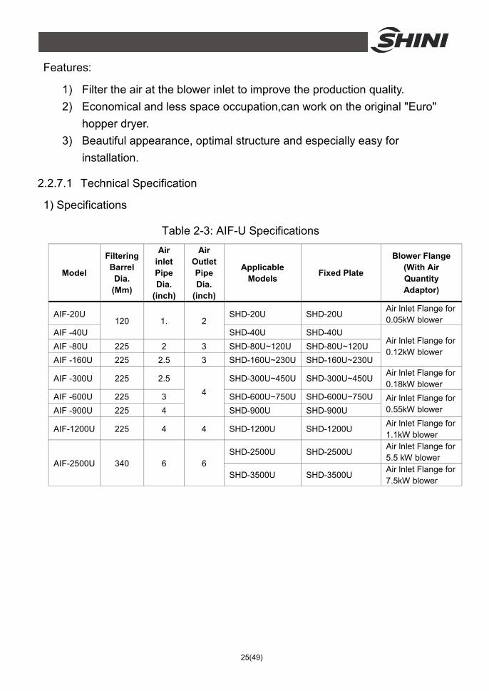
2.2.7 AIF-U "Euro" Blower Inlet Filter
AIF-U "Euro" blower inlet filter has filtering and dust-collecting function. Its design is for working with "Euro" dryer and can be installed at the backup air inlet of the blower. This machine features simple structure, easier installation and greatly improves the production efficiency. The built-inside filter can maintain the air clean so to ensure production quality. The machine has also configured with a backup air adjusting valve.
Model: AIF-80U
Picture 2-16: "Euro" Blower Inlet Filter
25(49)
Features:
1) Filter the air at the blower inlet to improve the production quality. 2) Economical and less space occupation,can work on the original "Euro"
hopper dryer. 3) Beautiful appearance, optimal structure and especially easy for
installation.
2.2.7.1 Technical Specification
1) Specifications
Table 2-3: AIF-U Specifications
Model
Filtering Barrel Dia.
(Mm)
Air inlet Pipe Dia.
(inch)
Air Outlet Pipe Dia.
(inch)
Applicable Models Fixed Plate
Blower Flange (With Air Quantity Adaptor)
AIF-20U 120 1. 2
SHD-20U SHD-20U Air lnlet Flange for 0.05kW blower
AIF -40U SHD-40U SHD-40U Air lnlet Flange for 0.12kW blower
AIF -80U 225 2 3 SHD-80U~120U SHD-80U~120U AIF -160U 225 2.5 3 SHD-160U~230U SHD-160U~230U
AIF -300U 225 2.5 4
SHD-300U~450U SHD-300U~450U Air lnlet Flange for 0.18kW blower
AIF -600U 225 3 SHD-600U~750U SHD-600U~750U Air lnlet Flange for 0.55kW blower AIF -900U 225 4 SHD-900U SHD-900U
AIF-1200U 225 4 4 SHD-1200U SHD-1200U Air lnlet Flange for 1.1kW blower
AIF-2500U 340 6 6 SHD-2500U SHD-2500U
Air lnlet Flange for 5.5 kW blower
SHD-3500U SHD-3500U Air lnlet Flange for 7.5kW blower
26(49)
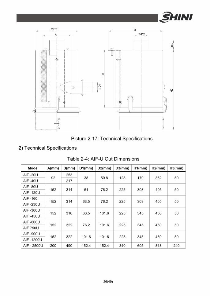
Picture 2-17: Technical Specifications
2) Technical Specifications
Table 2-4: AIF-U Out Dimensions
Model A(mm) B(mm) D1(mm) D2(mm) D3(mm) H1(mm) H2(mm) H3(mm)
AIF -20U 92
253 38 50.8 128 170 362 50
AIF -40U 217 AIF -80U
152 314 51 76.2 225 303 405 50 AIF -120U AIF -160
152 314 63.5 76.2 225 303 405 50 AIF -230U AIF -300U
152 310 63.5 101.6 225 345 450 50 AIF -450U AIF -600U
152 322 76.2 101.6 225 345 450 50 AIF 750U AIF -900U
152 322 101.6 101.6 225 345 450 50 AIF -1200U AIF - 2500U 200 490 152.4 152.4 340 605 818 240
27(49)
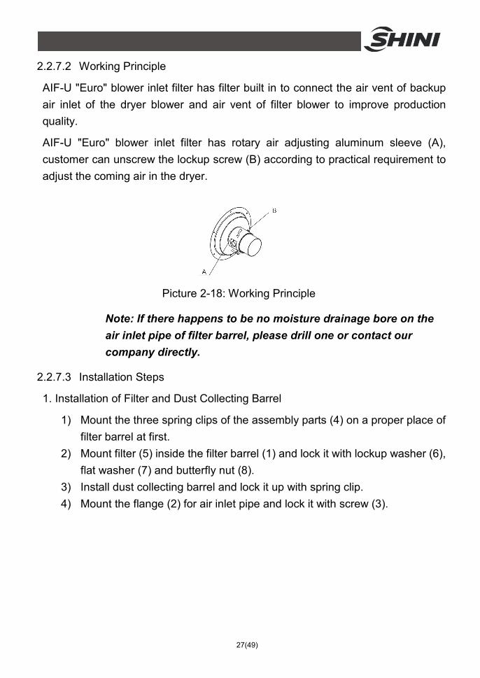
2.2.7.2 Working Principle
AIF-U "Euro" blower inlet filter has filter built in to connect the air vent of backup air inlet of the dryer blower and air vent of filter blower to improve production quality.
AIF-U "Euro" blower inlet filter has rotary air adjusting aluminum sleeve (A), customer can unscrew the lockup screw (B) according to practical requirement to adjust the coming air in the dryer.
Picture 2-18: Working Principle
Note: If there happens to be no moisture drainage bore on the air inlet pipe of filter barrel, please drill one or contact our company directly.
2.2.7.3 Installation Steps
1. Installation of Filter and Dust Collecting Barrel
1) Mount the three spring clips of the assembly parts (4) on a proper place of filter barrel at first.
2) Mount filter (5) inside the filter barrel (1) and lock it with lockup washer (6), flat washer (7) and butterfly nut (8).
3) Install dust collecting barrel and lock it up with spring clip. 4) Mount the flange (2) for air inlet pipe and lock it with screw (3).
28(49)
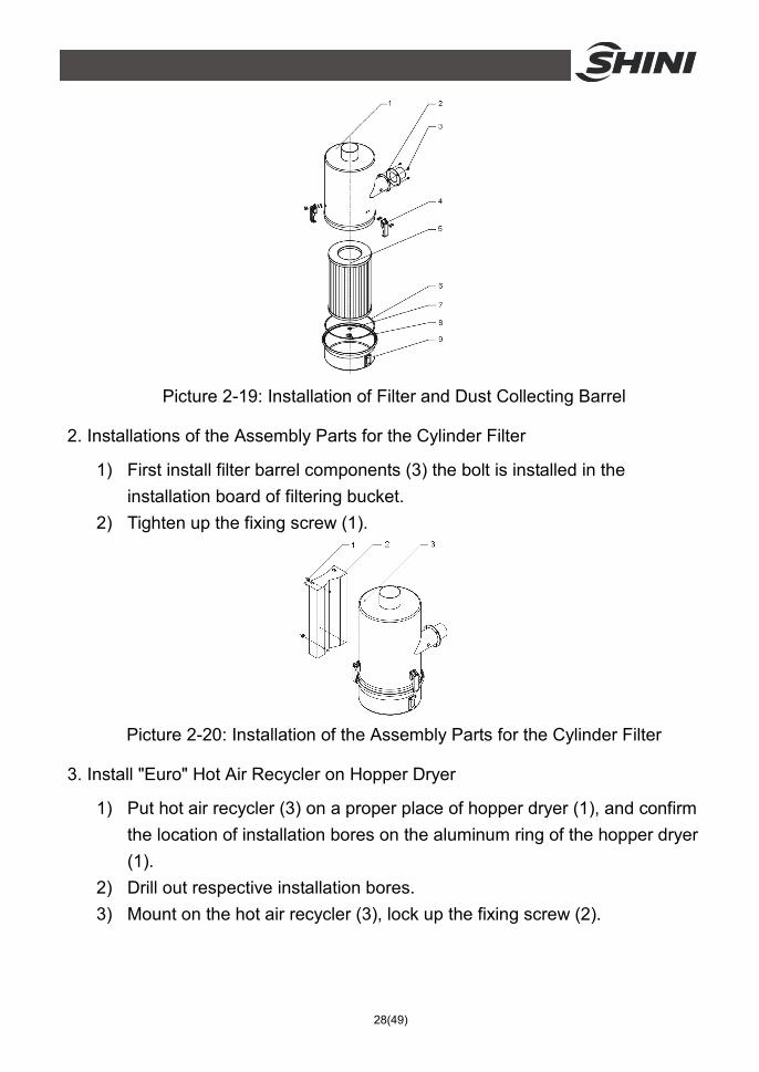
Picture 2-19: Installation of Filter and Dust Collecting Barrel
2. Installations of the Assembly Parts for the Cylinder Filter
1) First install filter barrel components (3) the bolt is installed in the installation board of filtering bucket.
2) Tighten up the fixing screw (1).
Picture 2-20: Installation of the Assembly Parts for the Cylinder Filter
3. Install "Euro" Hot Air Recycler on Hopper Dryer
1) Put hot air recycler (3) on a proper place of hopper dryer (1), and confirm the location of installation bores on the aluminum ring of the hopper dryer (1).
2) Drill out respective installation bores. 3) Mount on the hot air recycler (3), lock up the fixing screw (2).
29(49)
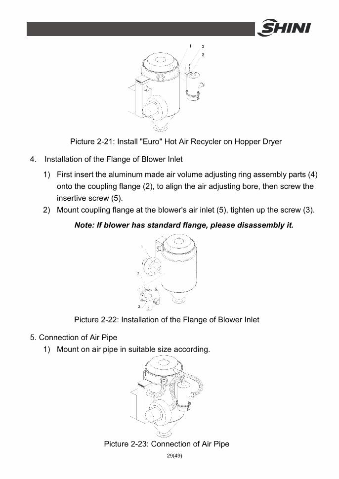
Picture 2-21: Install "Euro" Hot Air Recycler on Hopper Dryer
4. Installation of the Flange of Blower Inlet
1) First insert the aluminum made air volume adjusting ring assembly parts (4) onto the coupling flange (2), to align the air adjusting bore, then screw the insertive screw (5).
2) Mount coupling flange at the blower's air inlet (5), tighten up the screw (3).
Note: If blower has standard flange, please disassembly it.
Picture 2-22: Installation of the Flange of Blower Inlet
5. Connection of Air Pipe 1) Mount on air pipe in suitable size according.
Picture 2-23: Connection of Air Pipe
30(49)
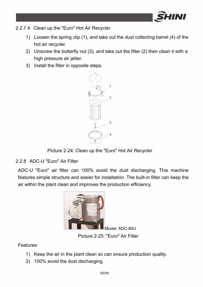
2.2.7.4 Clean up the "Euro" Hot Air Recycler
1) Loosen the spring clip (1), and take out the dust collecting barrel (4) of the hot air recycler.
2) Unscrew the butterfly nut (3), and take out the filter (2) then clean it with a high pressure air jetter.
3) Install the filter in opposite steps.
Picture 2-24: Clean up the "Euro" Hot Air Recycler
2.2.8 ADC-U "Euro" Air Filter
ADC-U "Euro" air filter can 100% avoid the dust discharging. This machine features simple structure and easier for installation. The built-in filter can keep the air within the plant clean and improves the production efficiency.
Model: ADC-80U Picture 2-25: "Euro" Air Filter
Features:
1) Keep the air in the plant clean so can ensure production quality. 2) 100% avoid the dust discharging.
31(49)
3) Economical and less space occupation, can work on the original "Euro" hopper dryer.
4) Beautiful appearance, optimal structure and especially easy for installation.
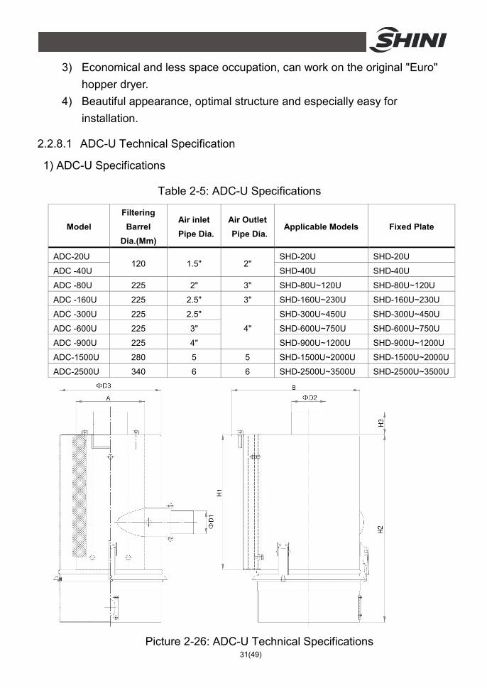
2.2.8.1 ADC-U Technical Specification
1) ADC-U Specifications
Table 2-5: ADC-U Specifications
Model Filtering Barrel
Dia.(Mm)
Air inlet Pipe Dia.
Air Outlet Pipe Dia.
Applicable Models Fixed Plate
ADC-20U 120 1.5" 2"
SHD-20U SHD-20U
ADC -40U SHD-40U SHD-40U
ADC -80U 225 2" 3" SHD-80U~120U SHD-80U~120U
ADC -160U 225 2.5" 3" SHD-160U~230U SHD-160U~230U
ADC -300U 225 2.5"
4"
SHD-300U~450U SHD-300U~450U
ADC -600U 225 3" SHD-600U~750U SHD-600U~750U
ADC -900U 225 4" SHD-900U~1200U SHD-900U~1200U
ADC-1500U 280 5 5 SHD-1500U~2000U SHD-1500U~2000U
ADC-2500U 340 6 6 SHD-2500U~3500U SHD-2500U~3500U
Picture 2-26: ADC-U Technical Specifications
32(49)
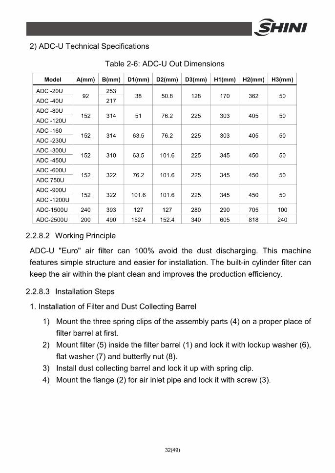
2) ADC-U Technical Specifications
Table 2-6: ADC-U Out Dimensions
Model A(mm) B(mm) D1(mm) D2(mm) D3(mm) H1(mm) H2(mm) H3(mm)
ADC -20U 92
253 38 50.8 128 170 362 50
ADC -40U 217
ADC -80U 152 314 51 76.2 225 303 405 50
ADC -120U
ADC -160 152 314 63.5 76.2 225 303 405 50
ADC -230U
ADC -300U 152 310 63.5 101.6 225 345 450 50
ADC -450U
ADC -600U 152 322 76.2 101.6 225 345 450 50
ADC 750U
ADC -900U 152 322 101.6 101.6 225 345 450 50
ADC -1200U
ADC-1500U 240 393 127 127 280 290 705 100
ADC-2500U 200 490 152.4 152.4 340 605 818 240
2.2.8.2 Working Principle
ADC-U "Euro" air filter can 100% avoid the dust discharging. This machine features simple structure and easier for installation. The built-in cylinder filter can keep the air within the plant clean and improves the production efficiency.
2.2.8.3 Installation Steps
1. Installation of Filter and Dust Collecting Barrel
1) Mount the three spring clips of the assembly parts (4) on a proper place of filter barrel at first.
2) Mount filter (5) inside the filter barrel (1) and lock it with lockup washer (6), flat washer (7) and butterfly nut (8).
3) Install dust collecting barrel and lock it up with spring clip. 4) Mount the flange (2) for air inlet pipe and lock it with screw (3).
33(49)
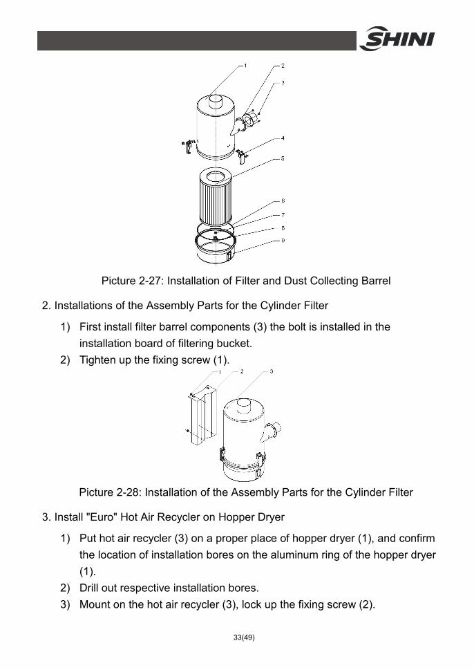
Picture 2-27: Installation of Filter and Dust Collecting Barrel
2. Installations of the Assembly Parts for the Cylinder Filter
1) First install filter barrel components (3) the bolt is installed in the installation board of filtering bucket.
2) Tighten up the fixing screw (1).
Picture 2-28: Installation of the Assembly Parts for the Cylinder Filter
3. Install "Euro" Hot Air Recycler on Hopper Dryer
1) Put hot air recycler (3) on a proper place of hopper dryer (1), and confirm the location of installation bores on the aluminum ring of the hopper dryer (1).
2) Drill out respective installation bores. 3) Mount on the hot air recycler (3), lock up the fixing screw (2).

34(49)
Picture 2-29: Install "Euro" Hot Air Recycler on Hopper Dryer
4. Installation of the Flange of Blower Inlet
1) First insert the aluminum made air volume adjusting ring assembly parts (4) onto the coupling flange (2), to align the air adjusting bore , then screw the insertive screw (5).
2) Mount coupling flange at the blower's air inlet (5), tighten up the screw (3).
Note: If blower has standard flange, please disassembly it.
Picture 2-30: Installation of the Flange of Blower Inlet
5. Connection of Air Pipe
1) Mount on air pipe in suitable size according.
Picture 2-31: Connection of Air Pipe
35(49)
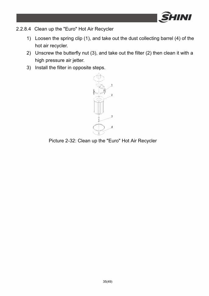
2.2.8.4 Clean up the "Euro" Hot Air Recycler
1) Loosen the spring clip (1), and take out the dust collecting barrel (4) of the hot air recycler.
2) Unscrew the butterfly nut (3), and take out the filter (2) then clean it with a high pressure air jetter.
3) Install the filter in opposite steps.
Picture 2-32: Clean up the "Euro" Hot Air Recycler
36(49)
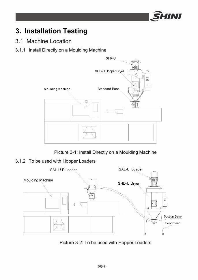
3. Installation Testing 3.1 Machine Location 3.1.1 Install Directly on a Moulding Machine
Picture 3-1: Install Directly on a Moulding Machine
3.1.2 To be used with Hopper Loaders
Picture 3-2: To be used with Hopper Loaders
37(49)
3.2 Power Connectors 1) Make sure voltage and frequency of the power source comply with those
indicated on the manufacture's plate, which is attached to the machine. 2) Power cable and earth connections should conform with local regulations. 3) Use independent power cable and ON / OFF switch. The cable's size
should not smaller than those applied in the control box. 4) The power cable connection terminals should be tightened securely. 5) The machine requires a 3-phase 4-wire power source, connect the power
lead (L1, L2, L3) to the live wires, and the earth (PE) to the ground. 6) Power supply requirements: Main power voltage: ± 5% Main power frequency: ± 2%
7) Specific power supply specifications please refer to the schematic model.
38(49)
4. Application and Operation 4.1 Control Panel
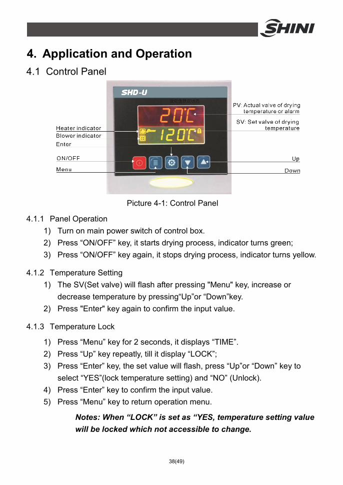
Picture 4-1: Control Panel
4.1.1 Panel Operation 1) Turn on main power switch of control box. 2) Press “ON/OFF” key, it starts drying process, indicator turns green; 3) Press “ON/OFF” key again, it stops drying process, indicator turns yellow.
4.1.2 Temperature Setting 1) The SV(Set valve) will flash after pressing "Menu" key, increase or
decrease temperature by pressing“Up”or “Down”key. 2) Press "Enter" key again to confirm the input value.
4.1.3 Temperature Lock
1) Press “Menu” key for 2 seconds, it displays “TIME”. 2) Press “Up” key repeatly, till it display “LOCK”; 3) Press “Enter” key, the set value will flash, press “Up”or “Down” key to
select “YES”(lock temperature setting) and “NO” (Unlock). 4) Press “Enter” key to confirm the input value. 5) Press “Menu” key to return operation menu.
Notes: When “LOCK” is set as “YES, temperature setting value will be locked which not accessible to change.
39(49)
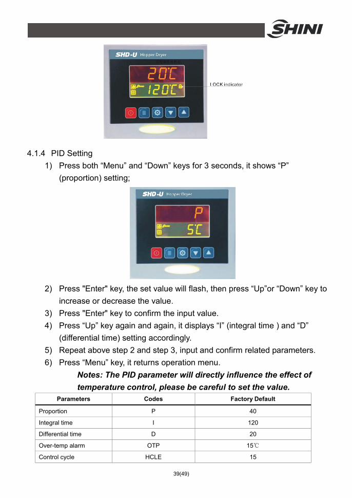
4.1.4 PID Setting 1) Press both “Menu” and “Down” keys for 3 seconds, it shows “P”
(proportion) setting;
2) Press "Enter" key, the set value will flash, then press “Up”or “Down” key to
increase or decrease the value. 3) Press "Enter" key to confirm the input value. 4) Press “Up” key again and again, it displays “I” (integral time ) and “D”
(differential time) setting accordingly. 5) Repeat above step 2 and step 3, input and confirm related parameters. 6) Press “Menu” key, it returns operation menu.
Notes: The PID parameter will directly influence the effect of temperature control, please be careful to set the value.
Parameters Codes Factory Default
Proportion P 40
Integral time I 120
Differential time D 20
Over-temp alarm OTP 15℃
Control cycle HCLE 15
40(49)
Blower delay FDLY 180
Temp. unit UNIT ℃
4.1.5 Intermittent Operation Setting
1) Hold “Menu” for about 2 secs. to set current time and week. Press “Up” or “Down” key to set start/stop function of AUTO timer, the time for RONE intermittent operation, the OFF time of ROFF intermittent operation, the ON time of RON intermittent operation.
4.1.6 One-week Timing Setting
1) After current time is set, hold “menu” for about 5 secs, press “Up” or “Down” key to set OFF1 (Mon. off time), OFF2(Tues. off time), OFF3 (Wed. off time), OFF4(Thur. off time), OFF 5(Fri. off time), OFF6(Sat. off time), OFF7(Sun.off time).
2) Hold “Menu” for about 7S, press “Up” or “Down” key to set ON1(Mon. start time), ON2(Tues. start time), ON3(Wed. start time), NO4(Thur. start time), ON5(Fri. start time), ON6(Sat. start time), ON7(Sun. start time).
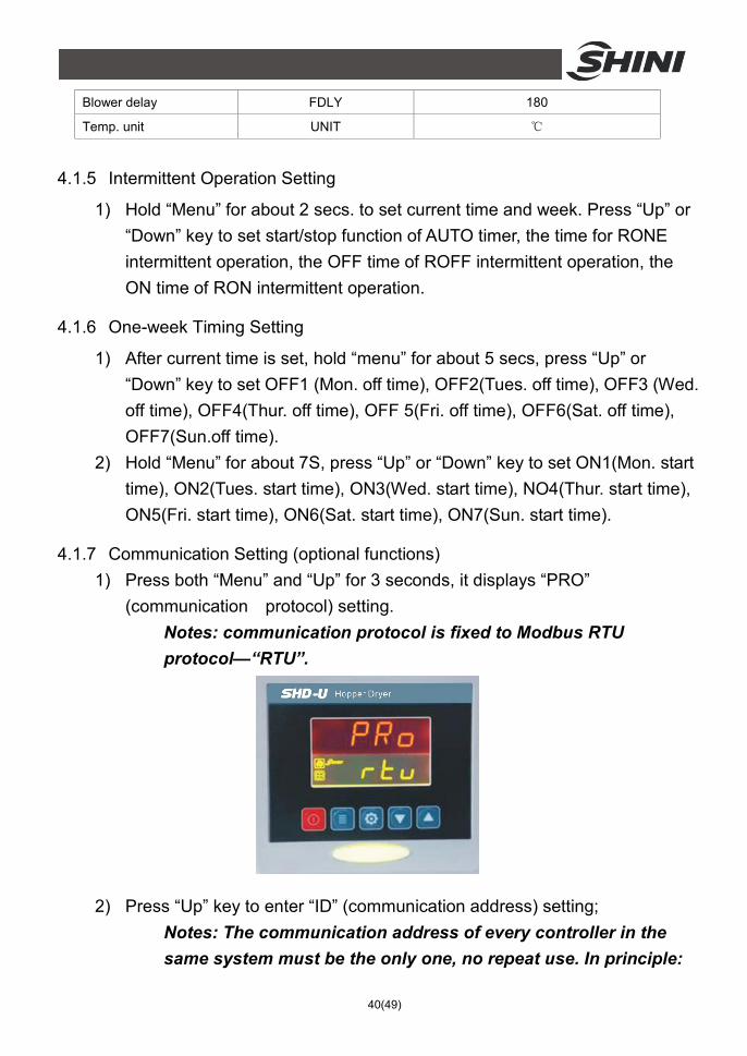
4.1.7 Communication Setting (optional functions) 1) Press both “Menu” and “Up” for 3 seconds, it displays “PRO”
(communication protocol) setting. Notes: communication protocol is fixed to Modbus RTU protocol—“RTU”.
2) Press “Up” key to enter “ID” (communication address) setting; Notes: The communication address of every controller in the same system must be the only one, no repeat use. In principle:
41(49)
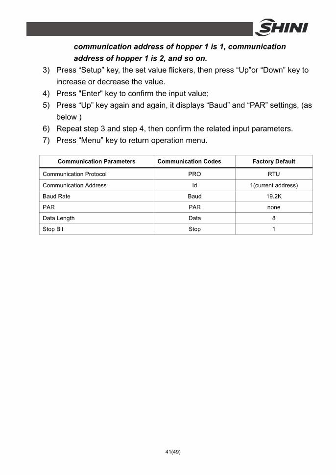
communication address of hopper 1 is 1, communication address of hopper 1 is 2, and so on.
3) Press “Setup” key, the set value flickers, then press “Up”or “Down” key to increase or decrease the value.
4) Press "Enter" key to confirm the input value; 5) Press “Up” key again and again, it displays “Baud” and “PAR” settings, (as
below ) 6) Repeat step 3 and step 4, then confirm the related input parameters. 7) Press “Menu” key to return operation menu.
Communication Parameters Communication Codes Factory Default
Communication Protocol PRO RTU
Communication Address Id 1(current address)
Baud Rate Baud 19.2K
PAR PAR none
Data Length Data 8
Stop Bit Stop 1
42(49)
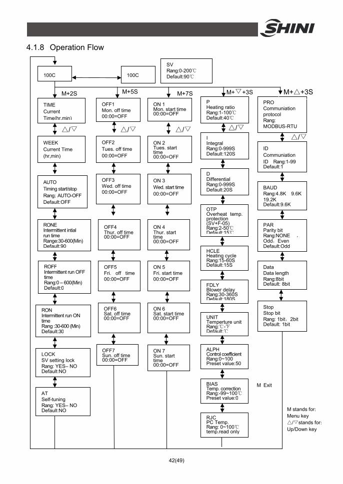
P Heating ratio Rang:1-100℃ Default:40 ℃
I Integral Rang:0-999S Default:120S
D Differential Rang:0-999S Default:20S
OTP Overheat temp. protection (SV+F-05) Rang:2-50℃ Default:15 ℃
100C
HCLE Heating cycle Rang:15-60S Default:15S
OFF1 Mon. off time 00:00=OFF
OFF2 Tues. off time 00:00=OFF
OFF3 Wed. off time 00:00=OFF
OFF4 Thur. off time 00:00=OFF
OFF5 Fri. off time 00:00=OFF
OFF6 Sat. off time 00:00=OFF
OFF7 Sun. off time 00:00=OFF
ON 1 Mon. start time 00:00=OFF
ON 2 Tues. start time 00:00=OFF
ON 3 Wed. start time 00:00=OFF
ON 4 Thur. start time 00:00=OFF
ON 5 Fri. start time 00:00=OFF
ON 6 Sat. start time 00:00=OFF
ON 7 Sun. start time 00:00=OFF
TIME Current Time(hr,min)
RON Intermittent run ON time Rang :30-600 (Min) Default:30
ROFF Intermittent run OFF time Rang:0 – 600(Min) Default:0
RONE Intermittent intial run time Range:30-600(Min) Default:90
UNIT Temperture unit Rang:℃-℉ Default: ℃
AUTO Timing start/stop Rang;AUTO-OFF Default:OFF
WEEK Current Time (hr,min)
FDLY Blower delay Rang:30-360S Default:180S
LOCK SV setting lock Rang: YES– NO Default:NO
PRO Communiation protocol Rang: MODBUS-RTU
ID Communiation ID Rang:1-99 Default:1
BAUD Rang:4.8K 9.6K 19.2K Default:9.6K
PAR Parity bit Rang:NONE ,Odd,Even Default:Odd
Data Data length Rang:8bit Default: 8bit
Stop Stop bit Rang: 1bit,2bit Default: 1bit
M+△+3S
SV Rang:0-200℃ Default:90℃ 100C
M+2S M+5S M+▽+3S M+7S
△/▽ △/▽ △/▽ △/▽
△/▽
M Exit
ALPH Control coefficient Rang:0~100 Preset value:50
BIAS Temp. correction Rang:-99~100℃ Preset value:0
RJC PC Temp. Rang: 0~100℃ temp.read only
AT Self-tuning Rang: YES– NO Default:NO M stands for:
Menu key △/▽stands for: Up/Down key
4.1.8 Operation Flow
43(49)
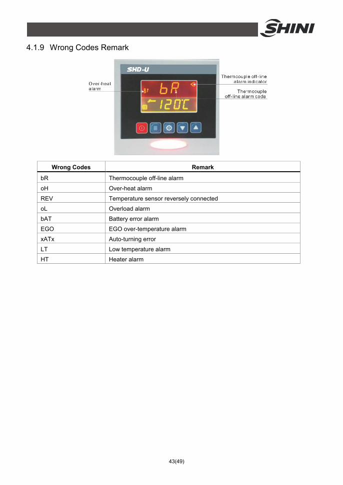
4.1.9 Wrong Codes Remark
Wrong Codes Remark
bR Thermocouple off-line alarm
oH Over-heat alarm
REV Temperature sensor reversely connected
oL Overload alarm
bAT Battery error alarm
EGO EGO over-temperature alarm
xATx Auto-turning error
LT Low temperature alarm
HT Heater alarm
44(49)
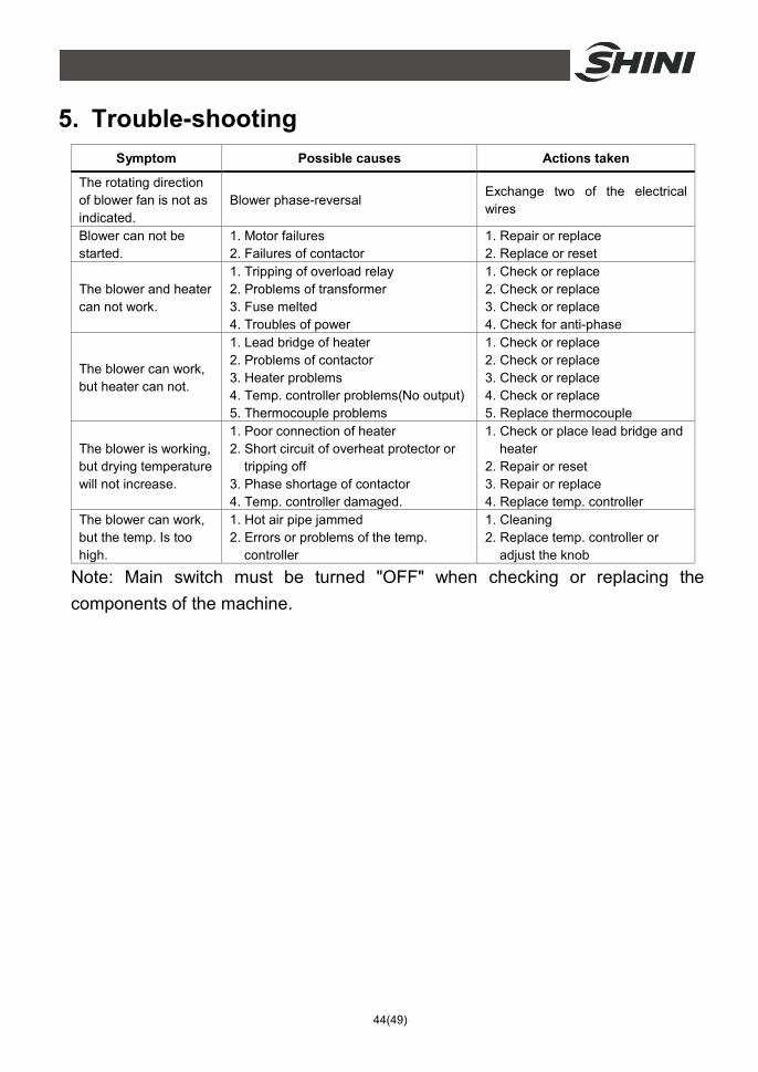
5. Trouble-shooting Symptom Possible causes Actions taken
The rotating direction of blower fan is not as indicated.
Blower phase-reversal Exchange two of the electrical wires
Blower can not be started.
1. Motor failures 2. Failures of contactor
1. Repair or replace 2. Replace or reset
The blower and heater can not work.
1. Tripping of overload relay 2. Problems of transformer 3. Fuse melted 4. Troubles of power
1. Check or replace 2. Check or replace 3. Check or replace 4. Check for anti-phase
The blower can work, but heater can not.
1. Lead bridge of heater 2. Problems of contactor 3. Heater problems 4. Temp. controller problems(No output) 5. Thermocouple problems
1. Check or replace 2. Check or replace 3. Check or replace 4. Check or replace 5. Replace thermocouple
The blower is working, but drying temperature will not increase.
1. Poor connection of heater 2. Short circuit of overheat protector or
tripping off 3. Phase shortage of contactor 4. Temp. controller damaged.
1. Check or place lead bridge and heater
2. Repair or reset 3. Repair or replace 4. Replace temp. controller
The blower can work, but the temp. Is too high.
1. Hot air pipe jammed 2. Errors or problems of the temp.
controller
1. Cleaning 2. Replace temp. controller or
adjust the knob
Note: Main switch must be turned "OFF" when checking or replacing the components of the machine.
45(49)
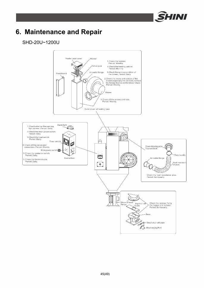
6. Maintenance and Repair SHD-20U~1200U
46(49)
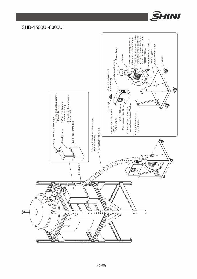
SHD-1500U~8000U
47(49)
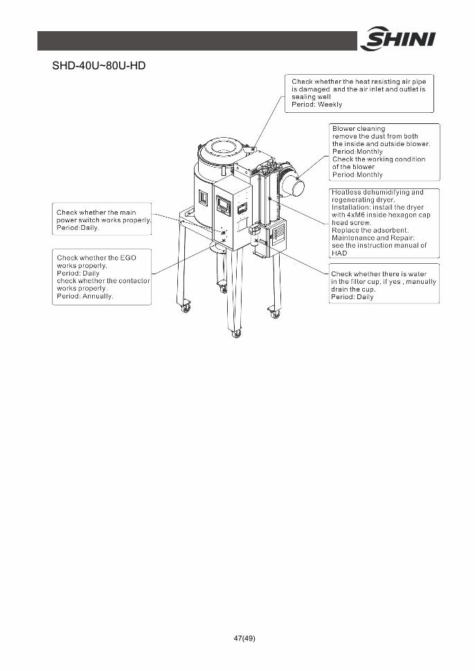
SHD-40U~80U-HD
48(49)
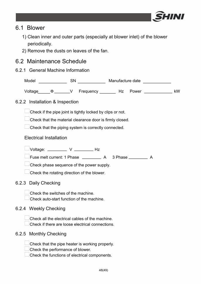
6.1 Blower 1) Clean inner and outer parts (especially at blower inlet) of the blower
periodically. 2) Remove the dusts on leaves of the fan.
6.2 Maintenance Schedule 6.2.1 General Machine Information
Model SN Manufacture date
Voltage Ф V Frequency Hz Power kW
6.2.2 Installation & Inspection
Check if the pipe joint is tightly locked by clips or not.
Check that the material clearance door is firmly closed.
Check that the piping system is correctly connected.
Electrical Installation
Voltage: V Hz
Fuse melt current: 1 Phase A 3 Phase A
Check phase sequence of the power supply.
Check the rotating direction of the blower.
6.2.3 Daily Checking
Check the switches of the machine. Check auto-start function of the machine.
6.2.4 Weekly Checking
Check all the electrical cables of the machine. Check if there are loose electrical connections.
6.2.5 Monthly Checking
Check that the pipe heater is working properly. Check the performance of blower. Check the functions of electrical components.
49(49)
6.2.6 Half-yearly Checking
Check if there are damages of heat-resistant hose or not. Check the process heater. Check the blower.