Embed Size (px)
Citation preview
Journal of Building Engineering 27 (2020) 100966
Available online 27 September 20192352-7102/© 2019 Elsevier Ltd. All rights reserved.
Shear behavior of cement stabilized rammed earth assemblages
G.S. Pavan a,*, S.N. Ullas b, K.S. Nanjunda Rao c
a Department of Civil Engineering, Shiv Nadar University, 201314, India b Centre for Sustainable Technologies, Indian Institute of Science, Bangalore, 560012, India c Department of Civil Engineering, Indian Institute of Science, Bangalore, 560012, India
A R T I C L E I N F O
Keywords: Rammed earth In-plane shear Diagonal shear Triplet Bonding technique Mohr-Coulomb failure envelope
A B S T R A C T
Adoption of rammed earth technology in building construction has witnessed a surge during the recent times and hence it is essential to understand the mechanical behavior of rammed earth under various loading conditions. In this study, in-plane shear behavior of cement stabilized rammed earth (CSRE) is assessed by conducting two types of tests namely (i) Direct shear test of CSRE causing shearing along two adjacent rammed earth layers similar to triplet shear test of masonry bed joints which is henceforth called as triplet test and (ii) Diagonal tension (shear) test of CSRE panels. Three types of bonding techniques between the rammed layers of CSRE are explored in this study, namely, (i) making conical dents which act as shear connectors between rammed earth layers, (ii) applying a coat of fresh cement slurry along the interfaces of rammed layers and (iii) combination of dents and fresh cement slurry and their influence in enhancing the interface shear strength of CSRE is assessed. The bonding techniques are adopted for both, triplet specimens and diagonal panels. Further, the effect of compressive stress normal to the rammed earth layers on the interface shear behavior of triplet specimens is examined. The different levels of normal pre-compression considered are 0.05 MPa, 0.3 MPa and 0.9 MPa. The triplet and diagonal tension (shear) tests on CSRE assemblages are conducted under both, dry and wet conditions. Shear behavior is assessed in terms of shear strength, shear modulus, strain at peak stress, post-peak behavior and failure patterns. Among the different bonding techniques assessed in this study, CSRE specimens with a coat of fresh cement slurry exhibited higher shear strength in comparison to specimens with other types of bonding techniques or no bonding technique. Further, CSRE triplet specimens exhibited steady increase in interface shear strength with increase in normal pre-compression, both in dry and wet conditions. Also, shear strength of CSRE was found to be lower in wet condition, in comparison to shear strength in dry condition, for all the bonding techniques. A Mohr-Coulomb failure envelope was developed for CSRE under wet and dry conditions based on the results of triplet tests conducted in this study. Overall, the study aims to understand the efficacy of the proposed bonding techniques in enhancing the shear strength of CSRE and the influence of normal pre- compression and moisture content on shear behavior of CSRE.
1. Introduction
Rammed earth walls are constructed by compacting processed soil- sand mixture with or without stabilizer, in layers within a rigid form-work. In general, un-stabilized rammed earth (URE) walls are thick and bulky in comparison to brick or stone masonry walls. In order to improve the strength and durability properties of rammed earth, stabilizing agents such as cement, lime etc. are added to the soil-sand mixture. Cement stabilized rammed earth (CSRE) walls are stronger, relatively slender and more durable. CSRE construction activity has witnessed a steady growth over the last decade and several structures have been
built worldwide. This renewed interest in earth based materials for construction has necessitated the need for understanding their me-chanical behavior.
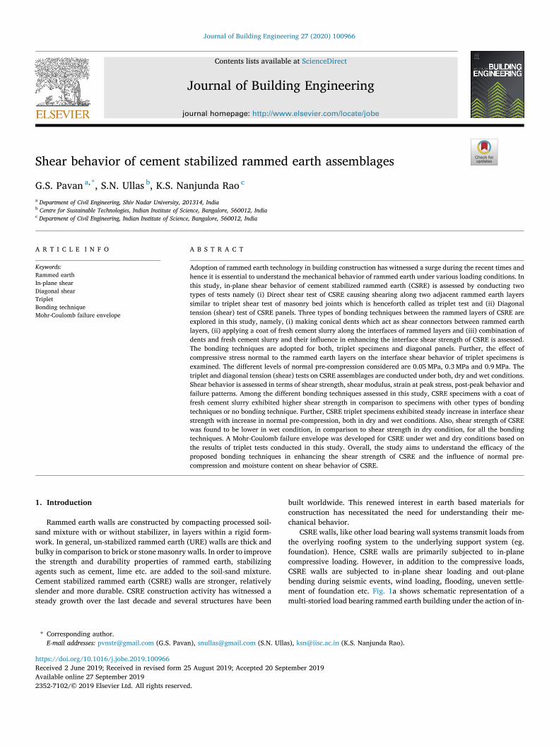
CSRE walls, like other load bearing wall systems transmit loads from the overlying roofing system to the underlying support system (eg. foundation). Hence, CSRE walls are primarily subjected to in-plane compressive loading. However, in addition to the compressive loads, CSRE walls are subjected to in-plane shear loading and out-plane bending during seismic events, wind loading, flooding, uneven settle-ment of foundation etc. Fig. 1a shows schematic representation of a multi-storied load bearing rammed earth building under the action of in-
* Corresponding author. E-mail addresses: [email protected] (G.S. Pavan), [email protected] (S.N. Ullas), [email protected] (K.S. Nanjunda Rao).
Contents lists available at ScienceDirect
Journal of Building Engineering
journal homepage: http://www.elsevier.com/locate/jobe
https://doi.org/10.1016/j.jobe.2019.100966 Received 2 June 2019; Received in revised form 25 August 2019; Accepted 20 September 2019
Journal of Building Engineering 27 (2020) 100966
2
plane lateral loads. Under such circumstances, load bearing rammed earth walls are subjected to both, in-plane lateral loads and vertical compression loads due to gravity. Fig. 1b shows schematic representa-tion of a framed construction with rammed earth walls as infills and subjected to in-plane lateral loading. Infills interact with the surround-ing beam-column system and contribute to the in-plane shear resistance. Fig. 1c shows the typical failure modes of walls during in-plane shear loading. The corner crushing and toe crushing failure modes occur mainly due to stress concentration at the corners. Shear slip in rammed earth occurs due to a shearing action along the interface of rammed earth layers. Diagonal tension failure occurs due to poor shear strength of rammed earth material. The internal forces acting within rammed earth elements which lead to shear slip failure and diagonal tension failure respectively is illustrated in Fig. 1d. Hence, understanding the shear behavior of CSRE material in terms of shear strength, shear bond
strength, shear deformation and failure modes is essential.
1.1. Previous studies on shear behavior of rammed earth and scope of the present investigations
The investigations carried out earlier on topics related to shear behavior of unstabilized and cement stabilized rammed earth are briefly reviewed. Walker and Morris [1] conducted an experimental study on in-plane shear behavior of cement stabilized rammed earth pre-stressed with steel rods. Hamilton et al. [2] conducted testing of full scale ram-med earth walls with post-tensioned reinforcement to assess the in-plane and out-of plane bending behavior. Cheah et al. [3] conducted a cyclic quasi-static test on a full scale rammed earth wall reinforced with flax fibres in order to assess the in-plane shear behavior of rammed earth wall. The rammed earth wall was around 6.2 m long and 2.4 m tall with a door and a window opening. Vertical steel reinforcement of 12 mm diameter were provided to infuse ductility to the rammed earth wall. Lateral load was applied with drift control and the maximum drift applied was 1.25 % of the height of the rammed earth wall. A non-ductile failure behavior was observed in the rammed earth wall panel. Failure modes observed were rocking of wall panels, shear failure and shear-slip failure modes. Cheah et al. [4] assessed the performance of existing shear test methods for evaluating the shear strength of cement stabilized rammed earth reinforced with natural fibers. The test methods considered were, (i) triaxial compression test and (ii) masonry triplet test. It was found that the shear strength of CSRE obtained from the two test methods was higher than the value of shear strength sug-gested by existing building codes. Cheah et al. [4] advocated triaxial compression test method for determining the shear strength of CSRE material. Nanjunda Rao et al. [5] assessed the shear strength of CSRE parallel and perpendicular to compacting layers using shear box test
Fig. 1. CSRE walls and infills under in-plane shear loading.
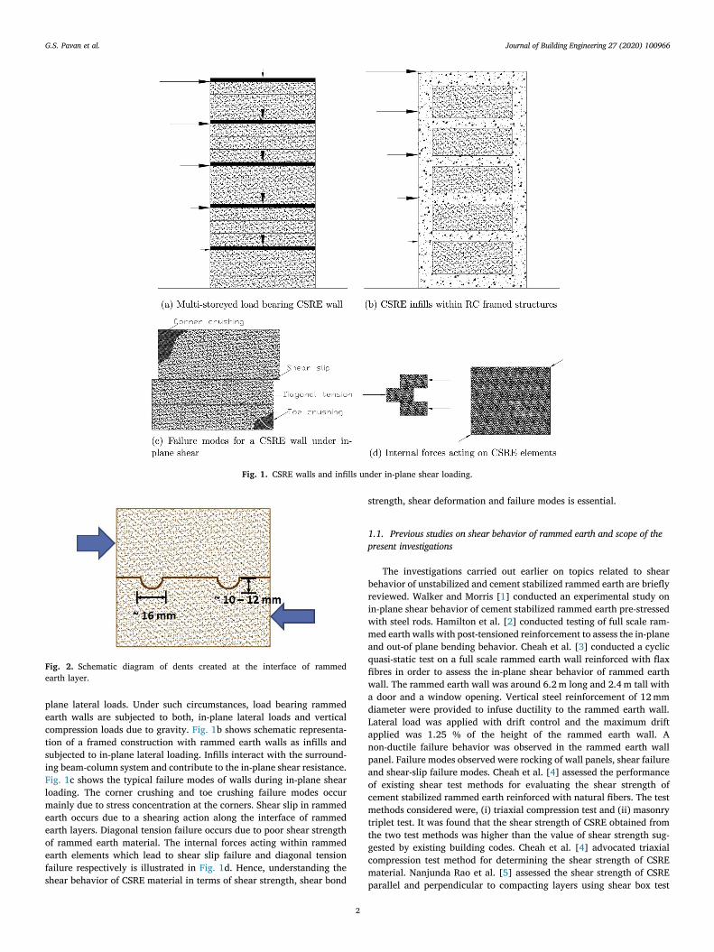
Fig. 2. Schematic diagram of dents created at the interface of rammed earth layer.
G.S. Pavan et al.
Journal of Building Engineering 27 (2020) 100966
3
apparatus. It was reported that shear strength increases with increase in normal stress in case of shear load parallel to compacting layers. How-ever, influence of normal stress on shear strength was not found in case of shear load perpendicular to compacting layers. Silva et al. [6] pre-sented a study on mechanical behavior of rammed earth material stablized by a geopolymeric binder obtained from the alkali activation of fly-ash. The rammed earth material was composed of granitic residual soil. Axial compression and diagonal compression tests were conducted on the geopolymer stabilized rammed earth specimens. Shear strength of the geopolymer stabilized RE specimens was found to be higher in comparison to the value of shear strength of URE reported in literature. Silva et al. [7] conducted a study on the effectiveness of injected mud grouts as a repair technique for URE with respect to shear behavior. Diagonal compression tests were conducted on rammed earth panels, both, un-repaired (before grout injection) and mud grout injected rammed earth panels. It was found that shear strength of panels injected with mud grout was around 60% the shear strength of panels before grout injection. Shear modulus of rammed earth panels with grout in-jection was around 10% of the shear modulus of panels without any grout injection. Miccoli et al. [8] conducted an experimental study to understand the mechanical behavior of URE under axial compression and diagonal tension (shear). Similar tests were conducted on adobe masonry and cob, and the behavior of three forms of earthen construc-tion was assessed. Miccoli et al. [9] adopted the results from their earlier study [8] and input them to a finite element model to simulate the non-linear behavior of rammed earth material. Total strain rotating crack model (TSRCM) was adopted for modeling rammed earth and Mohr-Coulomb failure criterion was adopted for the interface between rammed layers. Miccoli et al. [10] conducted cyclic shear-compression tests on unstabilized rammed earth panels to assess their in-plane shear behavior. A non-linear numerical analysis based on TSRCM was
performed and the model was found to be in good agreement with the experimental results. El-Nabouch et al. [11] conducted an experimental study on the static non-linear pushover analysis of URE walls with different aspect ratios to study the in-plane seismic performance. Ca-pacity curves were established and it was found that URE walls exhibited satisfactory performance in seismic zones with intensity, ‘very low’ to ‘moderate’ for few soil conditions. Miccoli et al. [12] explored the option of strengthening rammed earth wall panels with externally bonded polyster fabric strips. Pseudo dynamic cyclic testing of strengthened and unstrengthened, URE panels were conducted. The polyster fabric strips were employed to enhance the tensile strength. The study found that strengthening exercise aids in achieving the objective, however more experimental studies are required for further quantification. Arslan et al. [13] performed an experimental study to assess the in-plane shear behavior of, rammed earth walls and masonry walls. Rammed earth wall panels composed of different mixes (URE and CSRE) and masonry wall panels (composed of bricks and aerated concrete blocks), having exactly the same dimensions were subjected to displacement controlled in-plane reverse cyclic loading. A comparison in the structural behavior of these walls was made in terms of load carrying capacity, deformation ability corresponding to 1% and 3.5% drift ratio, energy dissipation, stiffness degradation and failure patterns. Rammed earth walls stabilized with 10% cement, exhibited a superior performance among all the wall panels with respect to all the parameters considered in this study. Structural behavior of URE walls was better in comparison to behavior of masonry walls composed of bricks. Cracks along the diagonals indi-cating shear failure was witnessed in most of the specimens. Riyono et al. [14] presented a hierarchical elasto-plastic constitutive model for modelling rammed earth material. The hierarchical model consisted of two components, one was a simple elasto-plastic model and the other was a complex elasto-plastic model. The simple elasto-plastic model accounted for plastic deformation either by tensile or shear failure. The complex model further accounted for isotropic hardening, shear soft-ening and a controlled tensile softening. Both the proposed models were validated by simulation of diagonal compression test and a pushover test. El-Nabouch et al. [15] conducted a numerical study to simulate Casagrande test or the direct shear test on rammed earth material using Coulomb criterion and homogenization model for porous material.
Based on the above discussion, studies on in-plane shear behavior of RE walls and panels have indicated that shear failure and shear-slip failure as the prominent modes of failure. Further, majority of the studies outlined above have focused on shear behavior of unstabilized rammed earth (either test on small specimens, panels or large scale testing of URE walls). Therefore, it is essential to assess the shear strength, shear bond strength and shear deformation ability of CSRE. Shear strength of CSRE may be assessed by conducting diagonal compression tests adhering to ASTM-E519 [16]. Shear bond strength or the interfacial shear strength of CSRE layers can be determined by performing the triplet test. Several studies present in literature [17,18,
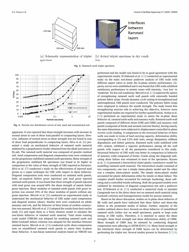
Fig. 3. Rammed earth triplet specimen.
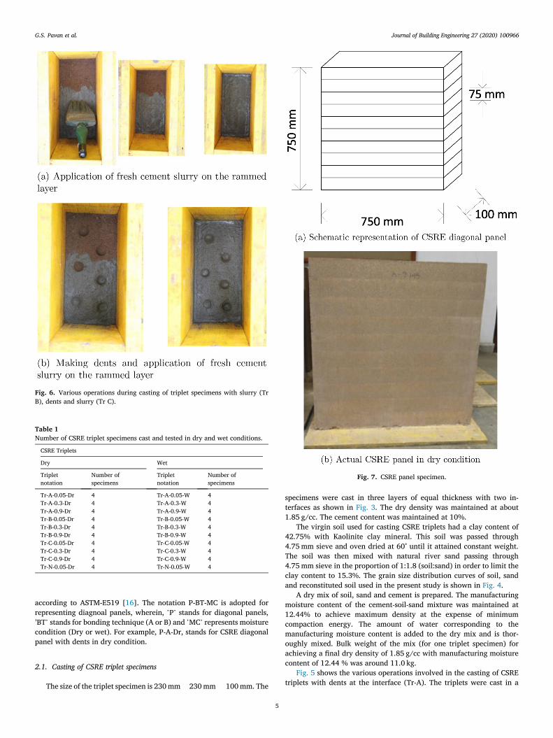
Fig. 4. Particle size distribution curves of soil, sand and reconstituted soil.
G.S. Pavan et al.

Journal of Building Engineering 27 (2020) 100966
4
19,20,21,22] have adopted triplet test method for assessing the brick-mortar interface strength of masonry.
The present study is focused on understanding the shear behavior of CSRE in terms of shear strength, shear bond strength and shear deformation-ability. Further, the present study explores usage of bonding techniques and their influence on the shear behavior of CSRE. The bonding techniques adopted in this study are, (i) creation of dents (ii) application of cement slurry at the interface and (iii) a combination of dents and cement slurry. These bonding techniques require minimum additional efforts in terms of labor and cost. A positive impact of these bonding techniques on shear behavior can further increase the efficiency of CSRE. This study also explores the influence of normal pre- compression on shear bond strength of CSRE. Varying levels of normal pre-compression is applied on rammed earth triplet specimens during triplet tests. Further details on bonding techniques, values of pre- compression and the number of specimens tested is outlined in the next section.
2. Experimental program
As described earlier, CSRE construction involves compaction of the moist cement-soil-sand mixture within a form work using wooden or steel rammers in horizontal layers. In order to achieve a better bond between two adjacent layers of rammed earth the following techniques were examined.
1. Blunt conical shaped dents were made using special steel rammer after compaction of each layer. The compacted moist cement-soil- sand mixture of the next layer which gets filled in the dents will act as a shear connector and aids in achieving bond between adjacent layers. The test specimens with dents are designated as ‘A’ series. A schematic diagram of the dents created at the interface of rammed
earth layer is shown in Fig. 2. Dents created had an average diameter of around 16 mm and a depth of around 10–12 mm.
2. The second technique considered is by applying a coat of fresh cement slurry (Water/Cement ¼ 1) using a brush on the compacted layer of moist soil-cement-sand mixture before starting the next layer of construction. The test specimens with a coat of cement slurry are designated as ‘B’ series.
3. The third technique examined is a combination of dents and appli-cation of fresh cement slurry on each layer before constructing the next layer. The test specimens in this category are designated as ‘C’ series.
4. The fourth technique examined was triplets without dents and no application fresh cement slurry between rammed layers. These control test specimens are designated as ‘N’.
CSRE triplet specimens were prepared using all the three bonding techniques discussed above and control triplet specimens, to examine the effectiveness of the techniques in terms of shear bond strength. In order to determine the influence of the magnitude of the compressive stress (normal to the compacted layers) on the shear bond strength, the triplet specimens were subjected to pre-compression perpendicular to the compacted layers. Values of pre-compression applied were 0.05 MPa, 0.3 MPa and 0.9 MPa. The notation Tr-BT-PC-MC is adopted to represent CSRE triplets wherein, ’Tr’ represents Triplet, ’BT’ stands for ’bonding technique’ (A, B, C, N), ’PC’ represents ’value of normal pre-compression’ (0.05, 0.3, 0.9) and ’MC’ stands for moisture condition (dry (Dr) or wet (W)). For example, Tr-B-0.05-Dr, represent triplets with slurry coating at 0.05 MPa normal pre-compression and under dry condition. Similarly, Tr-A-0.3-W represents triplets with dents under a pre compression of 0.3 MPa in wet condition.
CSRE panels for the diagonal tension (shear) tests were prepared for only the first two techniques, namely, (i) dents (A) (ii) coating of cement slurry (B). The diagonal tension tests on CSRE panels were conducted
Fig. 5. Various operations during casting of triplet specimens with dents (Tr A).
G.S. Pavan et al.
Journal of Building Engineering 27 (2020) 100966
5
according to ASTM-E519 [16]. The notation P-BT-MC is adopted for representing diagnoal panels, wherein, ’P’ stands for diagonal panels, ’BT’ stands for bonding technique (A or B) and ’MC’ represents moisture condition (Dry or wet). For example, P-A-Dr, stands for CSRE diagonal panel with dents in dry condition.
2.1. Casting of CSRE triplet specimens
The size of the triplet specimen is 230 mm � 230 mm � 100 mm. The
specimens were cast in three layers of equal thickness with two in-terfaces as shown in Fig. 3. The dry density was maintained at about 1.85 g/cc. The cement content was maintained at 10%.
The virgin soil used for casting CSRE triplets had a clay content of 42.75% with Kaolinite clay mineral. This soil was passed through 4.75 mm sieve and oven dried at 60∘ until it attained constant weight. The soil was then mixed with natural river sand passing through 4.75 mm sieve in the proportion of 1:1.8 (soil:sand) in order to limit the clay content to 15.3%. The grain size distribution curves of soil, sand and reconstituted soil used in the present study is shown in Fig. 4.
A dry mix of soil, sand and cement is prepared. The manufacturing moisture content of the cement-soil-sand mixture was maintained at 12.44% to achieve maximum density at the expense of minimum compaction energy. The amount of water corresponding to the manufacturing moisture content is added to the dry mix and is thor-oughly mixed. Bulk weight of the mix (for one triplet specimen) for achieving a final dry density of 1.85 g/cc with manufacturing moisture content of 12.44 % was around 11.0 kg.
Fig. 5 shows the various operations involved in the casting of CSRE triplets with dents at the interface (Tr-A). The triplets were cast in a
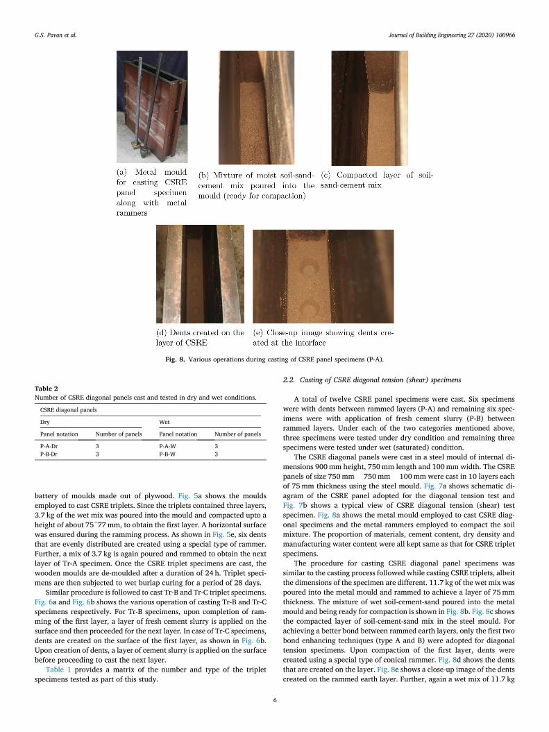
Fig. 6. Various operations during casting of triplet specimens with slurry (Tr B), dents and slurry (Tr C).
Table 1 Number of CSRE triplet specimens cast and tested in dry and wet conditions.
CSRE Triplets
Dry Wet
Triplet notation
Number of specimens
Triplet notation
Number of specimens
Tr-A-0.05-Dr 4 Tr-A-0.05-W 4 Tr-A-0.3-Dr 4 Tr-A-0.3-W 4 Tr-A-0.9-Dr 4 Tr-A-0.9-W 4 Tr-B-0.05-Dr 4 Tr-B-0.05-W 4 Tr-B-0.3-Dr 4 Tr-B-0.3-W 4 Tr-B-0.9-Dr 4 Tr-B-0.9-W 4 Tr-C-0.05-Dr 4 Tr-C-0.05-W 4 Tr-C-0.3-Dr 4 Tr-C-0.3-W 4 Tr-C-0.9-Dr 4 Tr-C-0.9-W 4 Tr-N-0.05-Dr 4 Tr-N-0.05-W 4
Fig. 7. CSRE panel specimen.
G.S. Pavan et al.
Journal of Building Engineering 27 (2020) 100966
6
battery of moulds made out of plywood. Fig. 5a shows the moulds employed to cast CSRE triplets. Since the triplets contained three layers, 3.7 kg of the wet mix was poured into the mould and compacted upto a height of about 75e77 mm, to obtain the first layer. A horizontal surface was ensured during the ramming process. As shown in Fig. 5e, six dents that are evenly distributed are created using a special type of rammer. Further, a mix of 3.7 kg is again poured and rammed to obtain the next layer of Tr-A specimen. Once the CSRE triplet specimens are cast, the wooden moulds are de-moulded after a duration of 24 h. Triplet speci-mens are then subjected to wet burlap curing for a period of 28 days.
Similar procedure is followed to cast Tr-B and Tr-C triplet specimens. Fig. 6a and Fig. 6b shows the various operation of casting Tr-B and Tr-C specimens respectively. For Tr-B specimens, upon completion of ram-ming of the first layer, a layer of fresh cement slurry is applied on the surface and then proceeded for the next layer. In case of Tr-C specimens, dents are created on the surface of the first layer, as shown in Fig. 6b. Upon creation of dents, a layer of cement slurry is applied on the surface before proceeding to cast the next layer.
Table 1 provides a matrix of the number and type of the triplet specimens tested as part of this study.
2.2. Casting of CSRE diagonal tension (shear) specimens
A total of twelve CSRE panel specimens were cast. Six specimens were with dents between rammed layers (P-A) and remaining six spec-imens were with application of fresh cement slurry (P-B) between rammed layers. Under each of the two categories mentioned above, three specimens were tested under dry condition and remaining three specimens were tested under wet (saturated) condition.
The CSRE diagonal panels were cast in a steel mould of internal di-mensions 900 mm height, 750 mm length and 100 mm width. The CSRE panels of size 750 mm � 750 mm � 100 mm were cast in 10 layers each of 75 mm thickness using the steel mould. Fig. 7a shows schematic di-agram of the CSRE panel adopted for the diagonal tension test and Fig. 7b shows a typical view of CSRE diagonal tension (shear) test specimen. Fig. 8a shows the metal mould employed to cast CSRE diag-onal specimens and the metal rammers employed to compact the soil mixture. The proportion of materials, cement content, dry density and manufacturing water content were all kept same as that for CSRE triplet specimens.
The procedure for casting CSRE diagonal panel specimens was similar to the casting process followed while casting CSRE triplets, albeit the dimensions of the specimen are different. 11.7 kg of the wet mix was poured into the metal mould and rammed to achieve a layer of 75 mm thickness. The mixture of wet soil-cement-sand poured into the metal mould and being ready for compaction is shown in Fig. 8b. Fig. 8c shows the compacted layer of soil-cement-sand mix in the steel mould. For achieving a better bond between rammed earth layers, only the first two bond enhancing techniques (type A and B) were adopted for diagonal tension specimens. Upon compaction of the first layer, dents were created using a special type of conical rammer. Fig. 8d shows the dents that are created on the layer. Fig. 8e shows a close-up image of the dents created on the rammed earth layer. Further, again a wet mix of 11.7 kg
Fig. 8. Various operations during casting of CSRE panel specimens (P-A).
Table 2 Number of CSRE diagonal panels cast and tested in dry and wet conditions.
CSRE diagonal panels
Dry Wet
Panel notation Number of panels Panel notation Number of panels
P-A-Dr 3 P-A-W 3 P-B-Dr 3 P-B-W 3
G.S. Pavan et al.
Journal of Building Engineering 27 (2020) 100966
7
was poured to obtain the second layer of the panel specimen. In case of P-B type panel specimens, upon compaction of the first layer, a coating of fresh cement slurry was applied. Upon application of the cement slurry, 11.7 kg of wet mix was again poured into the mould to obtain the second layer of the panel specimen.
The specimens were demoulded after 24 h of casting and later cured under wet burlap for 28 days. The specimens were air dried under shade inside the laboratory for about 2 months before testing which is referred to as dry condition testing of specimens. In the case of specimens referred to as wet condition testing, the specimens were immersed in water for 48 h before testing. The actual moisture content in the speci-mens at the time of testing has been determined and reported later. Table 2 provides a matrix of the number and type of the CSRE diagonal panels tested as part of this study.
2.3. Testing of CSRE triplet specimens
The triplet test is conducted to determine the interface shear strength of CSRE. Hence, CSRE triplets of size 230 mm � 230 mm � 100 mm are cast. CSRE triplets contain three layers each of thickness around 75 mm
and contains two interface layers. The aim of this experiment is to induce shearing action along these two interfaces.
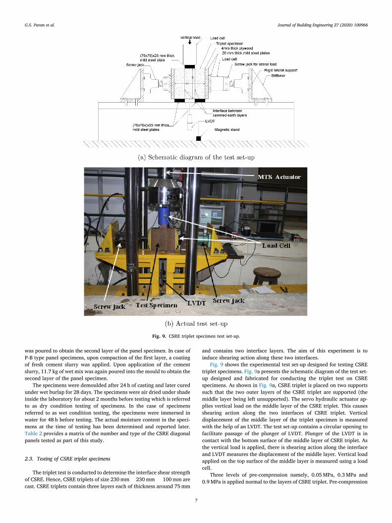
Fig. 9 shows the experimental test set-up designed for testing CSRE triplet specimens. Fig. 9a presents the schematic diagram of the test set- up designed and fabricated for conducting the triplet test on CSRE specimens. As shown in Fig. 9a, CSRE triplet is placed on two supports such that the two outer layers of the CSRE triplet are supported (the middle layer being left unsupported). The servo hydraulic actuator ap-plies vertical load on the middle layer of the CSRE triplet. This causes shearing action along the two interfaces of CSRE triplet. Vertical displacement of the middle layer of the triplet specimen is measured with the help of an LVDT. The test set-up contains a circular opening to facilitate passage of the plunger of LVDT. Plunger of the LVDT is in contact with the bottom surface of the middle layer of CSRE triplet. As the vertical load is applied, there is shearing action along the interface and LVDT measures the displacement of the middle layer. Vertical load applied on the top surface of the middle layer is measured using a load cell.
Three levels of pre-compression namely, 0.05 MPa, 0.3 MPa and 0.9 MPa is applied normal to the layers of CSRE triplet. Pre-compression
Fig. 9. CSRE triplet specimen test set-up.
G.S. Pavan et al.
Journal of Building Engineering 27 (2020) 100966
8
of 0.05 MPa is applied to mimic the situation of a low or no pre- compression normal to the layers of CSRE. This small value of pre- compression is necessary to restrain the outward rotation of the two outer layers of CSRE triplet. The highest value of the pre-compression (0.9 MPa) applied corresponds to the compressive stress developed at the base of the ground floor walls due to gravity load of a typical two to three storey residential building having a moderate roof span of about 4 m. The pre-compression normal to the interface of rammed earth layers (in the horizontal direction) is applied through two screw jacks, one on each side of the specimen, as shown in Fig. 9. Three metal steel plates of increasing size are placed in a triangular fashion in between the screw jacks and the triplet to ensure a uniform application of pre- compression stress onto the CSRE triplet. The value of pre- compression normal to CSRE layers is maintained at a constant level with the help of screw jacks. The entire test set-up is placed with-in a self equilibrating steel test frame which was specially designed and fabri-cated for conducting the test. The test frame is designed to remain rigid and resist the reaction forces arising out the vertical load and normal pre-compression forces.
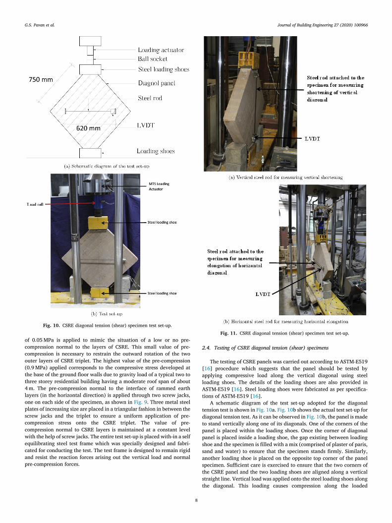
2.4. Testing of CSRE diagonal tension (shear) specimens
The testing of CSRE panels was carried out according to ASTM-E519 [16] procedure which suggests that the panel should be tested by applying compressive load along the vertical diagonal using steel loading shoes. The details of the loading shoes are also provided in ASTM-E519 [16]. Steel loading shoes were fabricated as per specifica-tions of ASTM-E519 [16].
A schematic diagram of the test set-up adopted for the diagonal tension test is shown in Fig. 10a. Fig. 10b shows the actual test set-up for diagonal tension test. As it can be observed in Fig. 10b, the panel is made to stand vertically along one of its diagonals. One of the corners of the panel is placed within the loading shoes. Once the corner of diagonal panel is placed inside a loading shoe, the gap existing between loading shoe and the specimen is filled with a mix (comprised of plaster of paris, sand and water) to ensure that the specimen stands firmly. Similarly, another loading shoe is placed on the opposite top corner of the panel specimen. Sufficient care is exercised to ensure that the two corners of the CSRE panel and the two loading shoes are aligned along a vertical straight line. Vertical load was applied onto the steel loading shoes along the diagonal. This loading causes compression along the loaded
Fig. 10. CSRE diagonal tension (shear) specimen test set-up. Fig. 11. CSRE diagonal tension (shear) specimen test set-up.
G.S. Pavan et al.

Journal of Building Engineering 27 (2020) 100966
9
diagonal, and tension along the other horizontal diagonal. A state of pure shear is created in the central region of the diagonal panel.
The deformation along the diagonals needs to be measured in order to determine shear strain. Fig. 11 shows the arrangement made for measuring deformation of the specimen along the vertical and hori-zontal diagonals of the test specimen. The measurement mechanism comprises of a steel rod and a LVDT. Steel rod is clamped at one of the ends of a diagonal of the panel specimen. The other end of the steel rod is in contact with LVDT, which is clamped at the opposite end of the di-agonal. This LVDT measures the deformation along the diagonal. The gauge length over which deformations of the specimen along the vertical and horizontal diagonals are measured is 620 mm.
The shear stress (τ), shear strain (γ) and shear modulus (G) of the masonry panels were calculated as per ASTM standard (ASTM-E519 [16]), as follows;
τ¼ 0:707PA
(1)
γ¼ εh þ εv (2)
G¼ τ=γ (3)
where A ¼ (hþw)t/2; h, w, t are height (750mm), width (750 mm) and thickness (100 mm) of the CSRE panel respectively, P is the applied load along the vertical diagonal, εh is the strain measured along the hori-zontal diagonal of the specimen and εv is the strain measured along the vertical diagonal of the specimen. Strains εh and εv were computed from the deformations measured using LVDT during the test and the gage length mentioned above.
3. Results and discussions
Results of the experiments conducted on CSRE triplet specimens and CSRE diagonal panels are presented and discussed here. Results ob-tained are discussed in terms of shear strength, load-deformation behavior, strain at peak stress, ultimate strain and modes of failure. Influence of different bonding techniques, moisture content and normal pre-compression on the above said parameters is assessed. Further, axial compression test on CSRE under wet and dry condition for the mix proportion considered in this study has been conducted by Tyagi [23].
Tyagi [23] has reported the compressive strength of CSRE to be 5.41 MPa and 3.01 MPa, under dry and wet conditions respectively.
3.1. CSRE triplet specimens
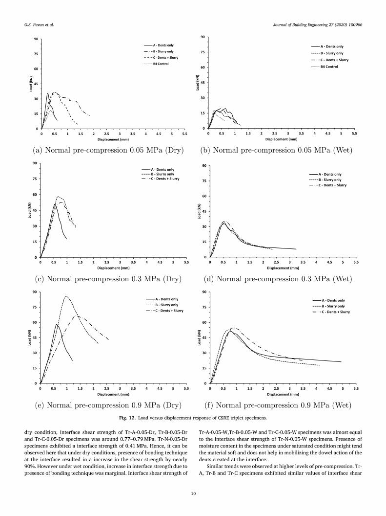
The results of the experiments conducted on CSRE triplet speciemens are presented in Table 3. Values of peak load, shear bond strength, displacement at peak stress and ultimate displacement for CSRE triplets with different bonding techniques in dry and wet conditions are pre-sented. Fig. 12a, 12c and 12e present the load versus displacement response of CSRE triplet specimens in dry condition subjected to a pre- compression of 0.05 MPa, 0.3 MPa and 0.9 MPa respectively. Fig. 12b, 12d and 12f present the load versus displacement response of CSRE triplet specimens in wet condition, subjected to a pre-compression of 0.05 MPa, 0.3 MPa and 0.9 MPa respectively.
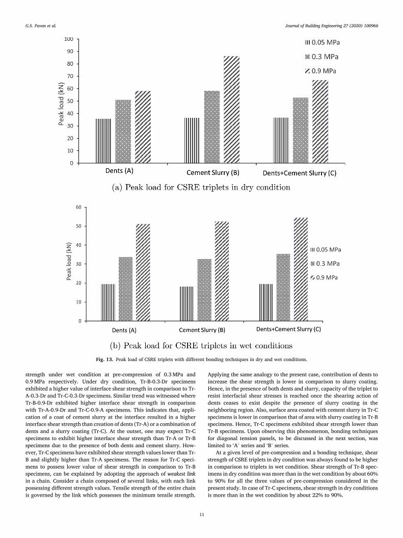
Fig. 13a and 13b present variation of the peak shear load sustained by CSRE triplets with different bonding techniques and normal pre- compression. Firstly, it can be observed that, there is a steady increase in the value of interface shear strength of CSRE triplets with increase in the level of normal pre-compression, for all types of bonding techniques and under both, dry and wet conditions. Interface shear strength of Tr-B- 0.3-Dr was around 59% higher than Tr-B-0.05-Dr specimens and inter-face shear strength of Tr-B-0.9-Dr was 48% higher in comparison to Tr- B-0.3-Dr triplets. In case of triplets with dents, interface shear strength of Tr-A-0.3-Dr triplets was 43.2% higher than Tr-A-0.05-Dr specimens. Percentage increase in the interface shear strength of Tr-A-0.9-Dr specimens was 13.9% in comparison to Tr-A-0.3-Dr. Similar trend was witnessed for triplet specimens with dents and layer of cement slurry. The lower increase in interface shear strength corresponding to increase in pre-compression from 0.3 to 0.9 MPa is along expected lines. Litera-ture on shear behavior of masonry indicates that shear strength in-creases with increase in normal pre-compression upto a certain extent (Lourenco and Rots [24]). Further, increase in normal pre-compression leads to a mild stagnation followed by a drop in the value of shear strength.
Further, at a pre-compression of 0.05 MPa and wet condition, interface shear strength of Tr-A, Tr-B and Tr-C specimens exhibited similar values of around 0.39-0.42 MPa. Further in wet condition and at 0.05 MPa pre-compression, triplet Tr-N specimens (without any bonding technique) exhibited an interface shear strength of around 0.39 MPa. In
Table 3 Shear strength and displacement values of CSRE triplets.
Triplet notation Peak load (kN) Stat. range (kN) Shear bond strength (MPa) Displ. at peak load (mm) Stat. range (mm) Ultimate displ. (mm) Stat. range (mm)
Tr-A-0.05-Dr 35.6 (8.9) 32.4–38.7 0.77 0.2306 (13) 0.20–0.26 0.585 (6.0) 0.55–0.62 Tr-A-0.3-Dr 51 (12.6) 42.1–57.0 1.11 0.540 (15.9) 0.45–0.66 0.985 (9.13) 0.88–1.10 Tr-A-0.9-Dr 58.1 (5.9) 53.6–61.8 1.26 0.609 (20.5) 0.49–0.76 1.210 (31.3) 0.92–1.74
Tr-B-0.05-Dr 36.41 (3.69) 34.3–37.4 0.79 0.4420 (10.03) 0.39–0.50 1.8394 (18.11) 1.45–2.26 Tr-B-0.3-Dr 58.21 (4.27) 54.71–60.51 1.26 0.6536 (8.68) 0.62–0.77 1.3316 (6.59) 1.25–1.45 Tr-B-0.9-Dr 86.01 (6.53) 78.0–90.2 1.87 0.9700 (7.38) 0.90–1.06 2.1724 (7.18) 1.96–2.34
Tr-C-0.05-Dr 36.67 (13.75) 29.61–41.14 0.79 0.5534 (3.73) 0.50–0.56 1.4162 (10.61) 1.20–1.54 Tr-C-0.3-Dr 52.71 (2.93) 51.1–54.4 1.14 0.8216 (6.47) 0.67–0.79 1.2289 (4.44) 1.10–1.24 Tr-C-0.9-Dr 66.74 (8.23) 61.9–74.4 1.45 1.3461 (9.78) 1.18–1.50 2.5777 (15.99) 2.22–3.16
Tr-N-0.05-Dr 18.82 (21.5) 14.1–24.0 0.41 0.4420 (33.01) 0.27–0.55 0.62 (23.05) 0.40–0.79
Tr-A-0.05-W 19.39 (13.10) 16.2–21.85 0.42 0.517 (33.75) 0.27–0.67 1.0572 (0.57) 1.39–1.41 Tr-A-0.3-W 33.74 (5.63) 32.0–36.9 0.73 0.5448 (7.17) 0.46–0.56 3.2421 (21.71) 2.33–4.25 Tr-A-0.9-W 51.09 (10.33) 47.2–58.0 1.11 0.7843 (14.7) 0.64–0.88 4.9352 (28.48) 2.99–6.58
Tr-B-0.05-W 18.1 (11) 15.8–20.6 0.39 0.339 (40.8) 0.21–0.53 1.22 (16.7) 1.06–1.55 Tr-B-0.3-W 32.60 (1.34) 31.9–33.0 0.71 0.5211 (8.63) 0.46–0.56 2.3752 (39.88) 1.33–3.31 Tr-B-0.9-W 52.74 (7.67) 48.7–56.7 1.14 0.7047 (6.97) 0.70–0.80 4.1234 (2.48) 4.07–4.28
Tr-C-0.05-W 19.52 (11.57) 16.4–21.7 0.42 0.4733 (10.28) 0.39–0.50 1.1356 (12.19) 1.01–1.30 Tr-C-0.3-W 35.39 (0.52) 35.3–35.7 0.77 0.5824 (11.89) 0.51–0.65 2.1582 (1.44) 2.13–2.19 Tr-C-0.9-W 54.51 (14.33) 48.3–65.5 1.18 0.9216 (8.60) 0.80–0.99 3.4726 (8.92) 3.07–3.83
Tr-N-0.05-W 17.81 (11.78) 14.8–19.55 0.39 0.2282 (9.89) 0.17–0.26 0.614 (22.5) 0.43–0.83
*Note: Values in the braces indicate coefficient of variation (COV) in percentage.
G.S. Pavan et al.
Journal of Building Engineering 27 (2020) 100966
10
dry condition, interface shear strength of Tr-A-0.05-Dr, Tr-B-0.05-Dr and Tr-C-0.05-Dr specimens was around 0.77–0.79 MPa. Tr-N-0.05-Dr specimens exhibited a interface strength of 0.41 MPa. Hence, it can be observed here that under dry conditions, presence of bonding technique at the interface resulted in a increase in the shear strength by nearly 90%. However under wet condition, increase in interface strength due to presence of bonding technique was marginal. Interface shear strength of
Tr-A-0.05-W,Tr-B-0.05-W and Tr-C-0.05-W specimens was almost equal to the interface shear strength of Tr-N-0.05-W specimens. Presence of moisture content in the specimens under saturated condition might tend the material soft and does not help in mobilizing the dowel action of the dents created at the interface.
Similar trends were observed at higher levels of pre-compression. Tr- A, Tr-B and Tr-C specimens exhibited similar values of interface shear
Fig. 12. Load versus displacement response of CSRE triplet specimens.
G.S. Pavan et al.
Journal of Building Engineering 27 (2020) 100966
11
strength under wet condition at pre-compression of 0.3 MPa and 0.9 MPa respectively. Under dry condition, Tr-B-0.3-Dr specimens exhibited a higher value of interface shear strength in comparison to Tr- A-0.3-Dr and Tr-C-0.3-Dr specimens. Similar trend was witnessed where Tr-B-0.9-Dr exhibited higher interface shear strength in comparison with Tr-A-0.9-Dr and Tr-C-0.9-A specimens. This indicates that, appli-cation of a coat of cement slurry at the interface resulted in a higher interface shear strength than creation of dents (Tr-A) or a combination of dents and a slurry coating (Tr-C). At the outset, one may expect Tr-C specimens to exhibit higher interface shear strength than Tr-A or Tr-B specimens due to the presence of both dents and cement slurry. How-ever, Tr-C specimens have exhibited shear strength values lower than Tr- B and slightly higher than Tr-A specimens. The reason for Tr-C speci-mens to possess lower value of shear strength in comparison to Tr-B specimens, can be explained by adopting the approach of weakest link in a chain. Consider a chain composed of several links, with each link possessing different strength values. Tensile strength of the entire chain is governed by the link which possesses the minimum tensile strength.
Applying the same analogy to the present case, contribution of dents to increase the shear strength is lower in comparison to slurry coating. Hence, in the presence of both dents and slurry, capacity of the triplet to resist interfacial shear stresses is reached once the shearing action of dents ceases to exist despite the presence of slurry coating in the neighboring region. Also, surface area coated with cement slurry in Tr-C specimens is lower in comparison that of area with slurry coating in Tr-B specimens. Hence, Tr-C specimens exhibited shear strength lower than Tr-B specimens. Upon observing this phenomenon, bonding techniques for diagonal tension panels, to be discussed in the next section, was limited to ‘A’ series and ‘B’ series.
At a given level of pre-compression and a bonding technique, shear strength of CSRE triplets in dry condition was always found to be higher in comparison to triplets in wet condition. Shear strength of Tr-B spec-imens in dry condition was more than in the wet condition by about 60% to 90% for all the three values of pre-compression considered in the present study. In case of Tr-C specimens, shear strength in dry conditions is more than in the wet condition by about 22% to 90%.
Fig. 13. Peak load of CSRE triplets with different bonding techniques in dry and wet conditions.
G.S. Pavan et al.
Journal of Building Engineering 27 (2020) 100966
12
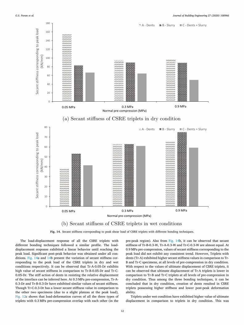
The load-displacement response of all the CSRE triplets with different bonding techniques followed a similar profile. The load- displacement response exhibited a linear behavior until reaching the peak load. Significant post-peak behavior was obtained under all con-ditions. Fig. 14a and 14b present the variation of secant stiffness cor-responding to the peak load of the CSRE triplets in dry and wet conditions respectively. It can be observed that Tr-A-0.05-Dr exhibits high value of secant stiffness in comparison to Tr-B-0.05-Dr and Tr-C- 0.05-Dr. The stiff action of dents in resisting the relative displacement of the interface can be inferred here. At 0.3 MPa pre-compression, Tr-A- 0.3-Dr and Tr-B-0.3-Dr have exhibited similar values of secant stiffness. Though Tr-C-0.3-Dr has a lower secant stiffness value in comparison to the other two specimens (due to a slight plateau at the peak load), Fig. 12c shows that load-deformation curves of all the three types of triplets with 0.3 MPa pre-compression overlap with each other (in the
pre-peak region). Also from Fig. 14b, it can be observed that secant stiffness of Tr-B-0.3-W, Tr-A-0.3-W and Tr-C-0.3-W are almost equal. At 0.9 MPa pre-compression, values of secant stiffness corresponding to the peak load did not exhibit any consistent trend. However, Triplets with dents (Tr-A) exhibited higher secant stiffness values in comparison to Tr- B and Tr-C specimens, at all levels of pre-compression in dry condition. With respect to the values of ultimate displacement of CSRE triplets, it can be observed that ultimate displacement of Tr-A triplets is lower in comparison to Tr-B and Tr-C triplets at all levels of pre-compression in dry condition. Thus among the three bonding techniques, it can be concluded that in dry condition, creation of dents resulted in CSRE triplets possessing higher stiffness and lower post-peak deformation ability.
Triplets under wet condition have exhibited higher value of ultimate displacement in comparison to triplets in dry condition. This was
Fig. 14. Secant stiffness correponding to peak shear load of CSRE triplets with different bonding techniques.
G.S. Pavan et al.
Journal of Building Engineering 27 (2020) 100966
13
observed for triplets with different bonding techniques and different levels of pre-compression. In wet condition, with increase in the level of pre-compression, there was a consistent increase in the value of ultimate displacement for CSRE triplets. This behavior was observed for triplets with all the different bonding techniques.
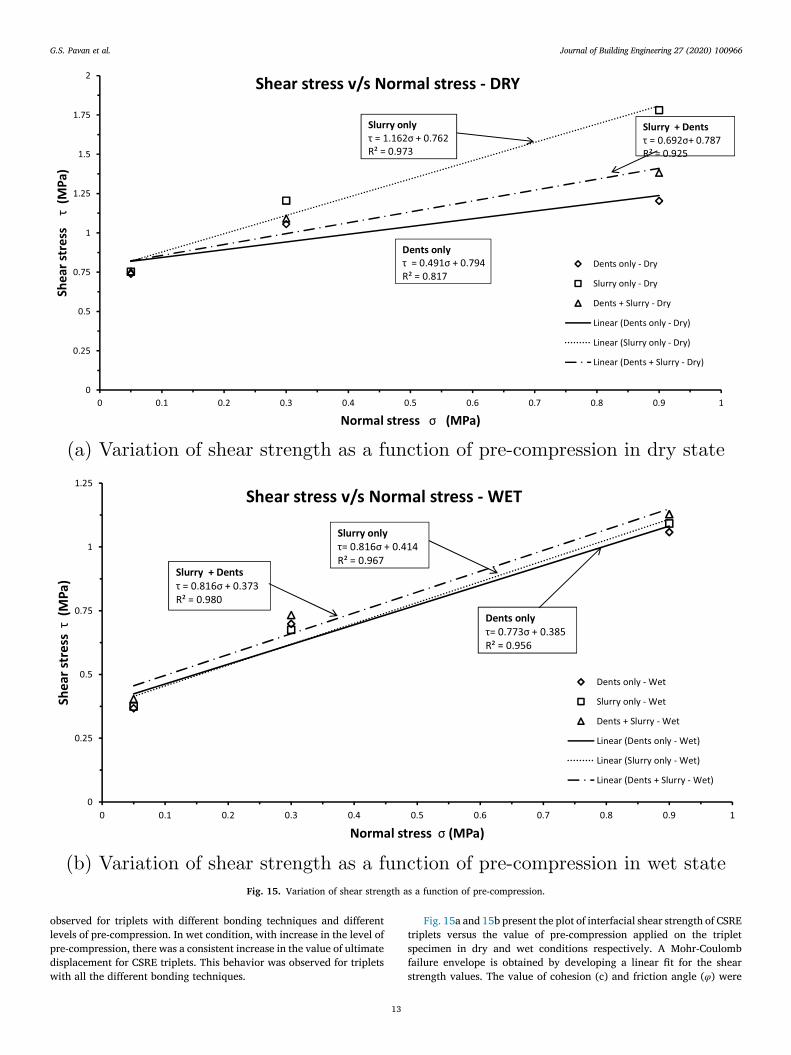
Fig. 15a and 15b present the plot of interfacial shear strength of CSRE triplets versus the value of pre-compression applied on the triplet specimen in dry and wet conditions respectively. A Mohr-Coulomb failure envelope is obtained by developing a linear fit for the shear strength values. The value of cohesion (c) and friction angle (φ) were
Fig. 15. Variation of shear strength as a function of pre-compression.
G.S. Pavan et al.

Journal of Building Engineering 27 (2020) 100966
14
obtained under both, dry and wet conditions, and for all the bonding techniques. Table 4 presents the values of cohesion (c) and friction angle (φ) for the different types of triplet specimens considered. The values of cohesion for Tr-A, Tr-B and Tr-C specimens is around 48%, 53 % and 47% of their corresponding cohesion values under dry condition respectively. Lower values of cohesion under wet condition is along expected lines because, soil is known to loose shear strength due to reduction in cohesive strength under saturated condition. Tr-B speci-mens possess a slightly higher value of cohesion under wet condition due to presence of cement slurry at the interface.
Table 4 Mohr-Coulomb parameters of CSRE Triplets.
CSRE Triplets
Dry Wet
c (MPa) φ (∘) c (MPa) φ (∘)
Tr-A 0.794 26.15 0.385 37.7 Tr-B 0.762 49.28 0.414 39.2 Tr-C 0.787 34.6 0.373 39.2
Table 5 Shear strength and shear strain values of CSRE diagonal panels.
Panel notation Shear strength (MPa) Statistical range Shear strain at peak stress Statistical range Ultimate shear strain Statistical range
P-A-Dr 1.2358 (5.25) 1.15–1.31 0.00061 (11.46) 0.00048–0.00063 0.00216 (1.65) 0.00208–0.00216 P-B-Dr 1.2357 (1.88) 1.21–1.26 0.00049 (1.49) 0.00049–0.0005 0.008299 (3.72) 0.0079–0.0086
P-A-W 0.75006 (10.4) 0.67–0.86 0.00043 (7.08) 0.00038–0.00045 0.00219 (49.9) 0.00048–0.0022 P-B-W 0.90291 (8.91) 0.761–0.948 0.00053 (31.3) 0.00025–0.00059 0.00097 (48.7) 0.00034–0.0011
*Note: Values in the braces indicate coefficient of variation (COV) in percentage.
Fig. 16. Shear stress versus shear strain of CSRE panels.
G.S. Pavan et al.
Journal of Building Engineering 27 (2020) 100966
15
3.2. CSRE diagonal tension (shear) specimens
The results of the experimental investigations on rammed earth di-agonal panels (P-A-Dr, P-A-W, P-B-Dr and P-B-W) is presented in Table 5.
The shear stress versus shear strain responses of the CSRE panels loaded along the vertical diagonal are presented in Fig. 16a and 16b for CSRE diagonal panels with dents (P-A) and diagonal panels with slurry coating (P-B) respectively. From the above Figures it can be seen that the shear strength of the CSRE panel specimens in dry condition with dents and cement slurry between rammed layers remained same and was about 1.23 MPa. However, in the wet condition, the shear strength of CSRE specimens with dents (DTS-A) was found to be 0.75 MPa and that of the specimens with cement slurry (DTS-B) was found to be 0.9 MPa. Hence, in wet condition, in comparison to creation of dents at the
interface, application of cement slurry at the interface is found to be more effective.
The shear stress-shear strain response of CSRE panels followed roughly a bi-linear profile until reaching the peak shear stress, for both P-A and P-B specimens. The shear panels P-A-Dr and P-B-Dr witnessed a sudden drop in the value of shear stress upon reaching the maximum value. Further, upon the drop in shear stress for P-A-Dr and P-B-Dr panels, considerable amount of shear deformation was recorded in the post-peak region. Between these two panels, ultimate shear strain of P- A-Dr panels was lower in comparison to P-B-Dr panels. In case of P-A-W, these panels exhibited a gradual reduction in shear stress upon reaching the maximum value. However, P-B-W panels exhibited a sudden drop in the shear stress upon reaching the maximum value.
Since the shear stress-shear strain relation of the CSRE was found to be bi-linear, shear modulus of CSRE was determined by secant method. The secant shear modulus of P-A-Dr and P-B-Dr specimens correspond-ing to shear strength was found to be 2000 MPa and 2480 MPa respec-tively. The secant shear modulus of P-A-W and P-B-W corresponding to shear strength was found to be 1700 MPa. However, the secant shear modulus corresponding to 50% of peak shear stress for P-A-Dr and P-B- Dr was found to be 3100 MPa and 3850 MPa respectively. The secant shear modulus corresponding to 50% of peak shear stress for P-A-W and P-B-W panels was found to be 2700 MPa and 3850 MPa respectively. The value of shear modulus corresponding to 50% peak shear stress for P-B specimens indicated that for P–B specimens, the secant shear modulus was not influenced by moisture content in the specimen at the time of testing.
The moisture content in the specimens at the time of testing was
Table 6 Failure patterns of CSRE triplets.
Triplet notation Failure pattern
Tr-A-0.05 Interface cracks Tr-A-0.3 Interface cracks Tr-A-0.9 Material failure Tr-B-0.05 Interface cracks Tr-B-0.3 Interface cracks Tr-B-0.9 Material failure Tr-C-0.05 Interface cracks Tr-C-0.3 Interface cracks Tr-C-0.9 Material failure
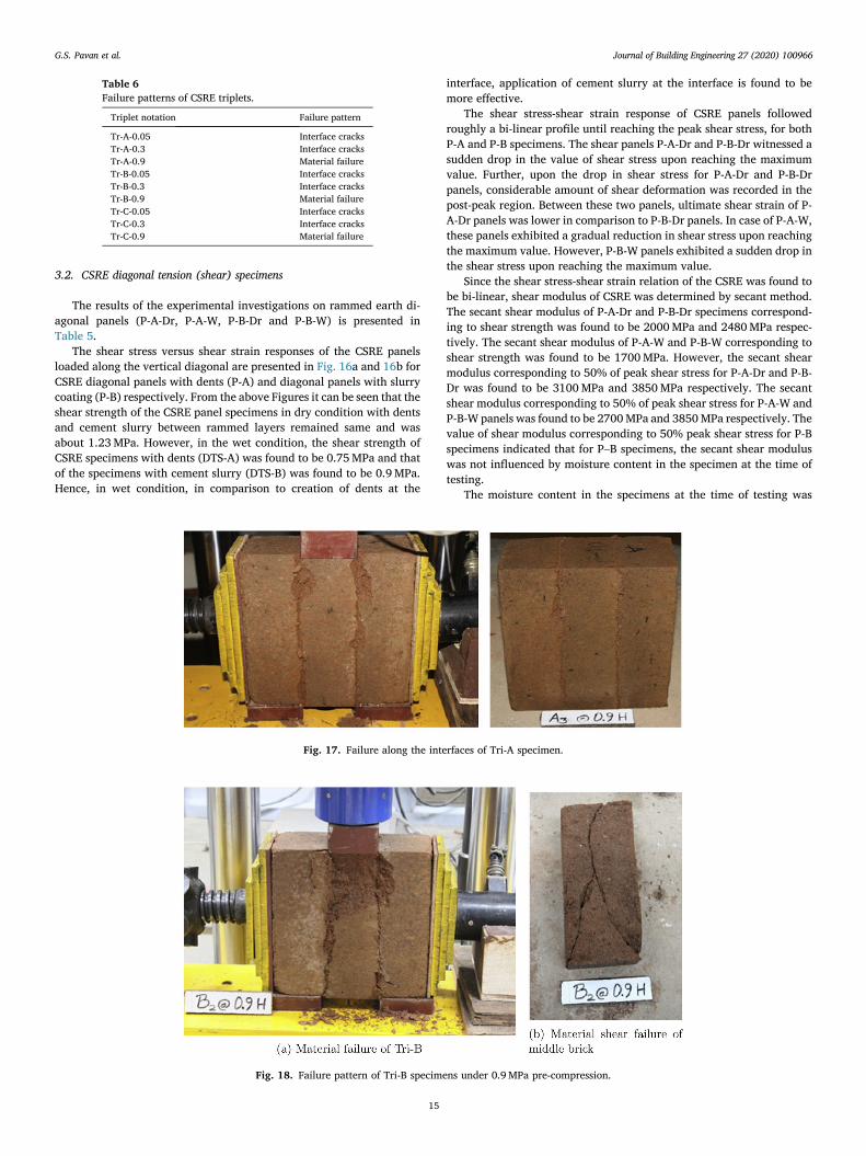
Fig. 17. Failure along the interfaces of Tri-A specimen.
Fig. 18. Failure pattern of Tri-B specimens under 0.9 MPa pre-compression.
G.S. Pavan et al.
Journal of Building Engineering 27 (2020) 100966
16
determined. For CSRE panels (diagonal tension (shear) test specimens) in dry condition the moisture content was found to be in the range of 2.6 to 3.1% and in the wet condition the moisture content was found to be in the range of 11.9 to 13.5%.
3.3. Failure patterns of CSRE triplet and diagonal tension (shear) specimens
CSRE triplets exhibited different types of failure patterns depending on the level of normal pre-compression applied, bonding technique and
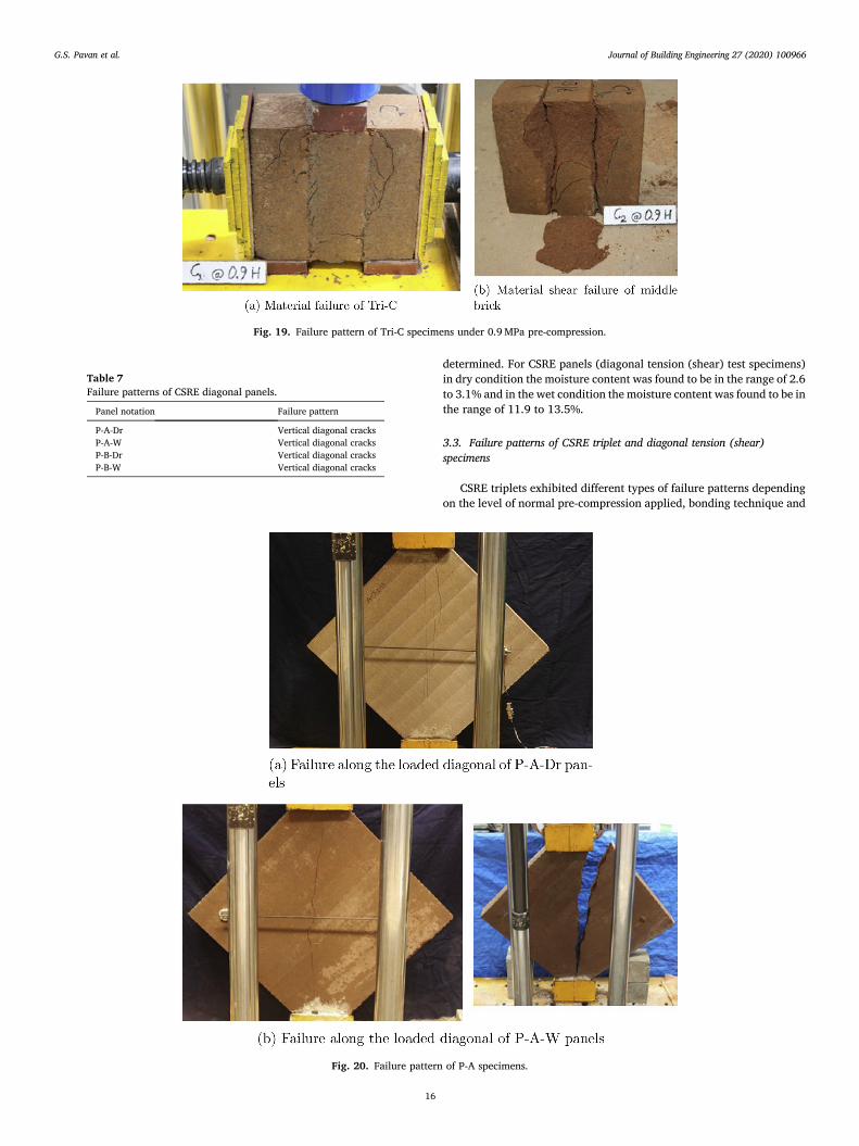
Fig. 19. Failure pattern of Tri-C specimens under 0.9 MPa pre-compression.
Table 7 Failure patterns of CSRE diagonal panels.
Panel notation Failure pattern
P-A-Dr Vertical diagonal cracks P-A-W Vertical diagonal cracks P-B-Dr Vertical diagonal cracks P-B-W Vertical diagonal cracks
Fig. 20. Failure pattern of P-A specimens.
G.S. Pavan et al.
Journal of Building Engineering 27 (2020) 100966
17
moisture content. A summary of the different modes of failure experi-enced by CSRE triplets is given in Table 6.
Failure mode of triplets at lower level of pre-compression which includes Tr-(A,B,C)-0.05-(D,W) and Tr-(A,B,C)-0.3-(D,W), was essen-tially due to development of cracks along the interface. Upon reaching the peak shear load, there was formation of cracks along the interface in the CSRE triplets. As the test progressed, there was gradual reduction in the value of load sustained, value of the displacement of the middle layer continued to increase and cracks began to grow wide. The test was continued until the load reached around 50% of the maximum value in the post-peak region. Width of the cracks grew significantly wide at this juncture.
Failure patterns of CSRE triplets at a pre-compression of 0.9 MPa was different in comparison to the failure patterns exhibited by triplets under pre-compression of 0.05 MPa and 0.3 MPa. The failure patterns of CSRE triplet specimens at a pre-compression of 0.9 MPa, are shown in Figs. 17 to 19. In the case of Tr-A specimens which had only dents for bonding between rammed layers, the failure was essentially along the interface, as observed in case of triplets with pre-compression of 0.3 MPa. How-ever in the case of Tr-B-0.9-(Dr,W) and Tr-C-0.9-(Dr,W) specimens, there was material failure in the middle portion of the specimen. Material
failure witnessed in Tr-B and Tr-C specimens subjected to 0.9 MPa is a premature failure of the specimen indicating the incomplete realization of the shear bond strength at the rammed earth interface. This indicates that, at a pre-compression of 0.9 MPa and with the presence of bonding techniques, interfacial shear strength of CSRE has increased to such an extent that it has led to failure of CSRE material prior to development of cracks along the interface.
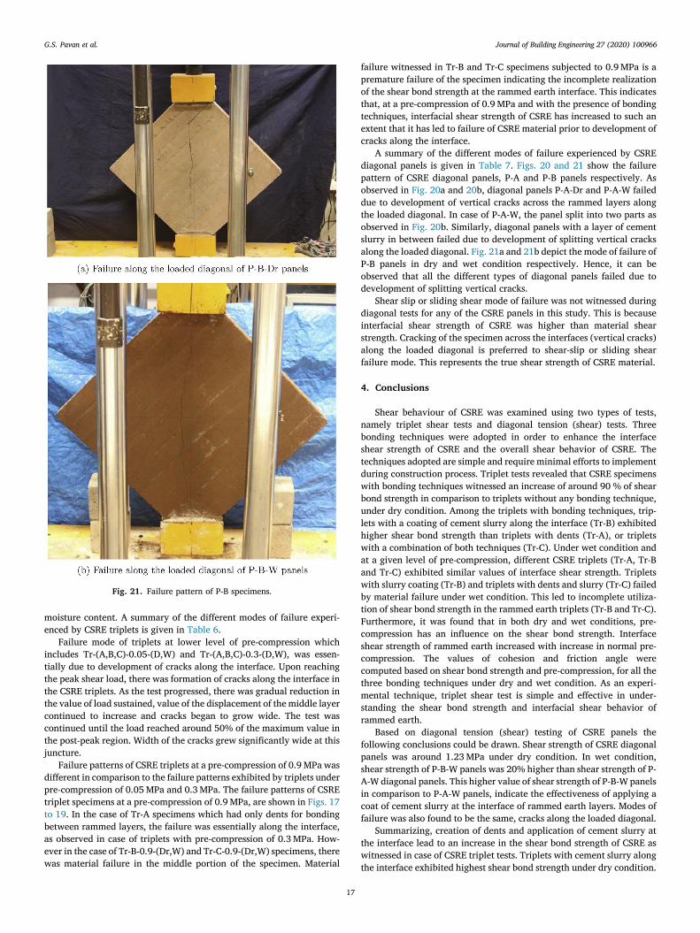
A summary of the different modes of failure experienced by CSRE diagonal panels is given in Table 7. Figs. 20 and 21 show the failure pattern of CSRE diagonal panels, P-A and P-B panels respectively. As observed in Fig. 20a and 20b, diagonal panels P-A-Dr and P-A-W failed due to development of vertical cracks across the rammed layers along the loaded diagonal. In case of P-A-W, the panel split into two parts as observed in Fig. 20b. Similarly, diagonal panels with a layer of cement slurry in between failed due to development of splitting vertical cracks along the loaded diagonal. Fig. 21a and 21b depict the mode of failure of P-B panels in dry and wet condition respectively. Hence, it can be observed that all the different types of diagonal panels failed due to development of splitting vertical cracks.
Shear slip or sliding shear mode of failure was not witnessed during diagonal tests for any of the CSRE panels in this study. This is because interfacial shear strength of CSRE was higher than material shear strength. Cracking of the specimen across the interfaces (vertical cracks) along the loaded diagonal is preferred to shear-slip or sliding shear failure mode. This represents the true shear strength of CSRE material.
4. Conclusions
Shear behaviour of CSRE was examined using two types of tests, namely triplet shear tests and diagonal tension (shear) tests. Three bonding techniques were adopted in order to enhance the interface shear strength of CSRE and the overall shear behavior of CSRE. The techniques adopted are simple and require minimal efforts to implement during construction process. Triplet tests revealed that CSRE specimens with bonding techniques witnessed an increase of around 90 % of shear bond strength in comparison to triplets without any bonding technique, under dry condition. Among the triplets with bonding techniques, trip-lets with a coating of cement slurry along the interface (Tr-B) exhibited higher shear bond strength than triplets with dents (Tr-A), or triplets with a combination of both techniques (Tr-C). Under wet condition and at a given level of pre-compression, different CSRE triplets (Tr-A, Tr-B and Tr-C) exhibited similar values of interface shear strength. Triplets with slurry coating (Tr-B) and triplets with dents and slurry (Tr-C) failed by material failure under wet condition. This led to incomplete utiliza-tion of shear bond strength in the rammed earth triplets (Tr-B and Tr-C). Furthermore, it was found that in both dry and wet conditions, pre- compression has an influence on the shear bond strength. Interface shear strength of rammed earth increased with increase in normal pre- compression. The values of cohesion and friction angle were computed based on shear bond strength and pre-compression, for all the three bonding techniques under dry and wet condition. As an experi-mental technique, triplet shear test is simple and effective in under-standing the shear bond strength and interfacial shear behavior of rammed earth.
Based on diagonal tension (shear) testing of CSRE panels the following conclusions could be drawn. Shear strength of CSRE diagonal panels was around 1.23 MPa under dry condition. In wet condition, shear strength of P-B-W panels was 20% higher than shear strength of P- A-W diagonal panels. This higher value of shear strength of P-B-W panels in comparison to P-A-W panels, indicate the effectiveness of applying a coat of cement slurry at the interface of rammed earth layers. Modes of failure was also found to be the same, cracks along the loaded diagonal.
Summarizing, creation of dents and application of cement slurry at the interface lead to an increase in the shear bond strength of CSRE as witnessed in case of CSRE triplet tests. Triplets with cement slurry along the interface exhibited highest shear bond strength under dry condition.
Fig. 21. Failure pattern of P-B specimens.
G.S. Pavan et al.

Journal of Building Engineering 27 (2020) 100966
18
Based on diagonal tension tests conducted on CSRE panels, P-B-W specimens exhibited higher shear strength than P-A-W specimens. Hence among the two bonding techniques, application of cement slurry along the interface of rammed earth layers is more effective than creation of dents.
Acknowledgment
The authors would like to gratefully acknowledge the financial support provided by DST, Govt. of India, New Delhi through the project Ref. No. SR/S3/MERC-0077/2010 for carrying out the research in-vestigations reported in this paper.
References
[1] R. Walker, H. Morris, Development of new performance based standards for earth building, in: Proceedings of the Australasian Structural Engineering Conference, Auckland, 30 September–2 October 1998, 1998, pp. 477–484.
[2] H. Hamilton, J. McBride, J. Grill, Cyclic testing of rammed-earth walls containing post-tensioned reinforcement, Earthq. Spectra 22 (4) (2006) 937–959.
[3] J. Cheah, T. Morgan, J. Ingham, Cyclic testing of a full-size stabilized, flax-fibre reinforced earth (uku) wall system with openings, in: Proceedings of the 14th World Conference on Earthquake Engineering. Beijing, China, 2008, pp. 12–17.
[4] J.S.J. Cheah, P. Walker, A. Heath, T.K.K.B. Morgan, Evaluating shear test methods for stabilised rammed earth, Proc. Inst. Civ. Eng. Constr. Mater. 165 (6) (2012) 325–334.
[5] K.S. Nanjunda Rao, B.V. Venkatarama Reddy, M.R. Gade, Strength and elastic properties of cement stabilized rammed earth, in: National Conference on Recent Developments in Civil engineering,VVIET, Mysore, Karnataka, 2011.
[6] R.A. Silva, D.V. Oliveira, T. Miranda, N. Cristelo, M.C. Escobar, E. Soares, Rammed earth construction with granitic residual soils: the case study of northern Portugal, Constr. Build. Mater. 47 (2013) 181–191.
[7] R.A.M. Silva, D.V. Oliveira, L. Schueremans, T.F. Miranda, J. Machado, Shear behaviour of rammed earth walls repaired by means of grouting, in: 9th International Masonry Conference, 2014.
[8] L. Miccoli, U. Müller, P. Fontana, Mechanical behaviour of earthen materials: a comparison between earth block masonry, rammed earth and cob, Constr. Build. Mater. 61 (2014) 327–339.
[9] L. Miccoli, D.V. Oliveira, R.A. Silva, U. Müller, L. Schueremans, Static behaviour of rammed earth: experimental testing and finite element modelling, Mater. Struct. 48 (10) (2015) 3443–3456.
[10] L. Miccoli, A. Drougkas, U. Müller, In-plane behaviour of rammed earth under cyclic loading: experimental testing and finite element modelling, Eng. Struct. 125 (2016) 144–152.
[11] R. El-Nabouch, Q.-B. Bui, O. Pl�e, P. Perrotin, Assessing the in-plane seismic performance of rammed earth walls by using horizontal loading tests, Eng. Struct. 145 (2017) 153–161.
[12] L. Miccoli, U. Müller, S. Pospí�sil, Rammed earth walls strengthened with polyester fabric strips: experimental analysis under in-plane cyclic loading, Constr. Build. Mater. 149 (2017) 29–36.
[13] M.E. Arslan, M. Emiro�glu, A. Yalama, Structural behavior of rammed earth walls under lateral cyclic loading: a comparative experimental study, Constr. Build. Mater. 133 (2017) 433–442.
[14] W.A. Riyono, E. Vincens, J.-P. Plassiard, A hierarchical elasto-plastic constitutive model for rammed earth, Constr. Build. Mater. 160 (2018) 351–364.
[15] R. El-Nabouch, J. Pastor, Q.-B. Bui, O. Pl�e, Limit analysis, rammed earth material and casagrande test, Compt. Rendus Mec. 346 (2) (2018) 98–109.
[16] ASTM-E519, Standard Test Method for Diagonal Tension (Shear) in Masonry Assemblages, ASTM International, 2015.
[17] V. Alecci, M. Fagone, T. Rotunno, M. De Stefano, Shear strength of brick masonry walls assembled with different types of mortar, Constr. Build. Mater. 40 (2013) 1038–1045.
[18] M. Ehsani, H. Saadatmanesh, A. Al-Saidy, Shear behavior of urm retrofitted with frp overlays, J. Compos. Constr. 1 (1) (1997) 17–25.
[19] N. Mojsilovi�c, Masonry elements with damp-proof course membrane: assessment of shear strength parameters, Constr. Build. Mater. 35 (2012) 1002–1012.
[20] G. Pavan, K. Nanjunda Rao, “Behavior of brick–mortar interfaces in frp- strengthened masonry assemblages under normal loading and shear loading, J. Mater. Civ. Eng. 28 (2) (2015), 04015120.
[21] P. Roca, G. Araiza, Shear response of brick masonry small assemblages strengthened with bonded frp laminates for in-plane reinforcement, Constr. Build. Mater. 24 (8) (2010) 1372–1384.
[22] M. Toma�zevi�c, Shear resistance of masonry walls and eurocode 6: shear versus tensile strength of masonry, Mater. Struct. 42 (7) (2009) 889–907.
[23] A. Tyagi, Fracture Properties of Cement Stabilized Rammed Earth, M.E. Thesis, Department of Civil Engineering, Indian Institute of Science, Bangalore, India, 2014.
[24] P.B. Lourenço, J.G. Rots, Multisurface interface model for analysis of masonry structures, J. Eng. Mech. 123 (7) (1997) 660–668.
G.S. Pavan et al.