Embed Size (px)
Citation preview

128 | P a g e
SHEAR DEMAND AND SHEAR DEFORMATION IN
EXTERIOR BEAM-COLUMN JOINTS
V.Renuka1, Dr.K.Rajasekhar
2
1,2Dept. of Civil Engineering, Siddartha Educational Academy Group of Institutions, Tirupati, (India)
2Professor, Dept. of Civil Engineering, SEAT, Tirupati, (India)
ABSTRACT
Beam-column joint is the gap in the modern ductile design of building. Especially under the earthquake
loading this is more susceptible to damage. Due to brittle nature of failure this type of failure cannot
be afford. Since 1970’s this areas is under the light of research, but with the paper of Park and Paul,
It got momentum. But still due to versatile nature of the joints core behaviour, the problem is still
persisting.
The entire researchers till 1970’s believed that RCC beam-column joints behave as rigid joint. So in
none of the pre 1970 building codes, they had not provided the confining reinforcement in the joints. With lot
of damage and destruction of building due to shear force under earthquake force most of the code committee
to introduce the confinement in the joints.
But recently due to use of high grade of concrete and better quality control in the RCC structures,
confinements in the joints as per the new provision of codes leading us to the problem of the
congestion. It has been observed at many construction sites that this congestion leads to poor
workmanship at the joints, which actually making the joint more vulnerable than previous. Researcher
has been working on this area to counter act by Increasing the size of the joints, Using the steel fiber in
the joints, Using GRFP to wrap the joints, Prestressing the beam including the joint, Using of the crossed
rebar at the joint cores. Due to prestressing of joint through the beam has not been so effective and
economical, the present paper come up with the direct way of prestessing the joints. This paper tries
to combine the benefits of the crossed rebar and prestressing in the joints together.
The present work is divided into two phase. In first phase few sample of normal low and medium high
building has been chosen and designed according to the IS 456:2000(LSD) and shear force are calculated
as per ACI 352-02. From this phase we come to conclusion that first two stories have higher shear force
demand and these are the joints more susceptible to congestion and prestessing of joint core should be
implemented to these joints only.
In the second phase two exterior beam-column joint from previous experimental programme. They were
model and analyse using ANSYS v13. Improvement in the ultimate load and failure pattern has been
detailed in the thesis. From this phase we come to conclusion that this
new technique is more effective than the previous prestressing technique of joints.
Keywords: Beam-Column Joint, RCC, Crossed-Rebar, Prestress, ANSYS, Shear Force

129 | P a g e
I. INTRODUCTION
Past is witness to many devastation and destruction of structure due to joint failures due to earthquakes. Beam-
column joint has not been area of research for many decades because scientist believes that beam
column joint behave as rigid joint with no deformation contributed by it. Beam-column joint has no
problem in itself until the dead and live loads are concern. As soon as lateral loads, i.e. seismic force,
comes into picture it will become a critical problem. This problem has not been solved completely till
date. It can be seen how the time has evolved to witness the development in the understanding of the
beam-column joint core behaviour, specially related to shear force and shear deformation. Still we have
translucent vision about this area. In the following discussion an endeavour is just tried to remove the
dust from this area so as to make it as clear as pure water.
As we know that, practically we can’t construct the structure earthquake-proof, so there must be way out to
earthquake problem. And we are fortunate enough that the solution come in only one term and that is
ductility. Make the structure enough ductile and forget about the force which is going to come on it. So in
short the solution to the problem of earthquake is ductility. So whatever going to come in the way of
ductility and your structure you have to kill that, simple enough to understand? So in this process of removing
our enemy through the research of 70 years in the seismic design, only beam-column joint shear failure
is left behind. Before getting into the objective and scope of the project work on the beam-column joints an
introduction is presented in the following sections.
1.1What is Beam to Column joint?
The portion of the column where beam is use to join it is called beam-column joint. Beam- column joints are
classified into three types based on the number of beams ending into the column
i) Interior Beam-Column joints ii) Exterior Beam-Column joints iii) Corner Beam-Column joints
1.2 Background Problem with the Beam-Column Joints
Beam-column joint is subjected to very high shear forces due to pulling of top rebar and pushing of
bottom rebar’s or vice versa in the concrete structure especially during the earthquake loading. These
very high shear force leads to the brittle damage, which can’t be accepted in the earthquake resistant building
which has to be ductile in nature to deal with unseen forces. Building damaged by the joint failure is shown
in Fig 1.1.2.
These failures on the technical ground can be classified into three types as mentioned below:
i) Shear failure of the joint before plastic hinge in the beam, J.
ii) Shear failure of the joint after the plastic hinge in the beam, BJ.
iii) Bond failure of the longitudinal due to slippage of the bar due to excess tension in the bar. From through
study of the literatures on the beam-column joints it was interpreted that these individual or the combination of
failure are depend on the sets of few parameter which are presented in the tabular form below.
The researchers are mainly concern about three things about the beam to column joints. i. Deformation due
to joint behaviour,
ii. Joint shear demand and
iii. Joint shear capacity.

130 | P a g e
II. MECHANICS OF BEAM-COLUMN JOINT CORE: SHEAR FORCE
Shear force is very critical in the earthquake resistance design of the structure because of it induce brittle
failures. But if the structure is subjected to lateral force due to wind or earthquakes most of the shear
force is being concentrated in the joint cores, which leads to the brittle failure of the many structure in the
past earthquakes. Even though the mechanic of the calculation of the shear force in the joint core is very
simple it had been ignore for many decades with the wrong assumption of the rigid joint behaviour. The
detail mathematical formulae to calculate the shear force demand and shear force capacity has been
well presented in Chapter 2.
III. MECHANICS OF BEAM-COLUMN JOINT: SHEAR DEFORMATION
Deformation of the joints contributes significant lateral drift of the story and the global story displacement.
But due incapability to calculate the shear deformation most of the code till present assume the rigid
joint behaviour of the joint. Which may sometime leads to significant error in the calculation of the
max story displacement. Estimation or calculation of lateral story drift due to shear deformation of the joint
is very challenging. From the past many scientist has tried to solve this riddle. They proposed many
different type of models starting with the rigid joint assumption, matrix method based on the central line
analysis, implementation of the panel zone concept to add the shear deformation, adding rotational hinge
and the use of full scale finite element analysis etc. with every advancement they are moving forward to
the accurate estimate of the shear deformation. Detailed version will be discussed in the literature review
section. Here we will over view the status of estimation and contribution of shear deformation in the global
deformation of the building. Following are the deformation model propose in the timeline orders
1. Conventional rigid joint model
2. ASCE/SEI 41-06 joint model
3. Modelling inelastic joint action within the beam-column element
4. Rotational hinge models
5. Continuum models and FEM
IV. FINITE ELEMENT ANALYSIS
FEA is a powerful computational technique for approximate solutions to a variety of complex "real-world"
engineering problems having complex domains subjected to general boundary conditions. FEA has become
an essential step in the design or modelling of a physical phenomenon in various engineering disciplines
including civil engineering, aeronautical engineering and many more. The second phase of this project is
completed with the finite element software ANSYSv13. An introduction about the finite element method has
been presented in following sections.
4.1 Methodology
The present work is divided in two phases. The first phase is to find the critical joints with respect to the
reinforcement congestion and shear force demand. And second phase deals with the effectiveness of the
direct prestessing of the beam-column joint in mitigating the brittle failure at the joint to the ductile failure
131 | P a g e
in the beam. An introduction to methodology of both phase are presented here. More detailed one is presented
in the chapter 3.
4.2 First Phase Methodology
1. Few samples of the low and midrise 2D building are selected with standard dimensions and
standard loading.
2. All building is being designed as per IS 456:2000(LSD).
3. Shear force has been calculated as per ACI:352-02
4. Critical joints have been shorted out on which the prestressing is being applied as going to be
proposed in the phase 2.
4.3 Second Phase Methodology
1. Two exterior beam-column joints which were going to fail at joints due to shear failure have been
selected from the literature.
2. Both the joint has been modelled in ANSYS v13 as per the experiment performed in the literature to
verify the result.
3. Direct prestressing is implemented in ANSYS model on both of the joints to see the improvement in shear
deformation, shear strength, shear demand and failure pattern.
V. SHEAR FORCE DEMAND AND CAPACITY
Bakir and Boduroglu (2002) proposed a model for the prediction of the shear strength of the beam-column
joints. The paper considers the three new parameters for the first time to predict the shear strength of the
joint. These parameters are beam longitudinal reinforcement ratio, beam-column joint aspect ratio and the
influence of stirrups ratio. It concluded that beam longitudinal reinforcement ratio has positive effect on
the joint shear strength. Because the influence of beam longitudinal reinforcement ratio is taken into
account, the proposed equation predicts that the joint shear strength is proportional to (hb/hc)0.61.The
paper also concluded that the column axial load has no effect on the shear strength but the high column
axial load and high column longitudinal reinforcement is required to prevent the column failure.
Park and Mosalman (2009) given a shear strength model of the exterior beam-column joints without shear
reinforcement, which can be useful in required confinement reinforcement to prevent the shear damage.
Muhsen and Umemura (2011) proposed a model to estimate the strength of the interior beam-column
joint with consideration of the confinement reinforcement and axial force. The proposed model is similar to
the current ACI and AJI codes with little modification in the effective area of the joint panel and
considering the confinement due to axial force in the column and confinement reinforcement in the joint
core. None of the codes has considered the confinement effect in the estimation of the shear strength of the
beam-column joint. Pimanmasa and Chaimahawanb (2010) present paper to prevent the beam-column joints
by enlarging the joint area. The paper concluded that the joint enlargement as shown in the Fig:
2.2.1 is a very effective method to reduce the shear stress transmission in the joint panel and hence effective in
preventing the damage. There has been also change in the failure mode with the relocation of the plastic
hinge from the face of the beam to the face of the enlarge section. The model is well explain with the strut and

132 | P a g e
tie model.
Kang and Mitra (2012) proved that the increasing development length, head thickness and head size and
decreasing joint shear demand gives better beam-column joint performance. The paper also showed that
increasing rebar yield strength, joint confinement reinforcement and axial load leads to unpredictability of the
performance of the beam-column joints. After going through the every parameter they found that joint shear
demand and bar yield stress are two major parameters from influential point of view.
Jung et. al. (2009) has given a method to predict the deformation of the RC beam-column joints with BJ
(joint failure after hinge formation in the beam) joint failure. Also it shows that the deformation of the joint
increases with the decrease in the beam rebar. The paper has given method to calculate the ductility
capacity of the beam-column joints.
VI. BEAM-COLUMN JOINT DEFORMATION MODELS
Modelling of the building against earthquake forces and any other types of lateral forces is based on the
inelastic plastic hinge formation in the beam, slab and wall etc. But following researches proved the contrary
(Meinheit and Jirsa, 1977; Durrani and Wight, 1985; Park and Ruitong 1988; Leon, 1990; Clyde et al., 2000;
Mazzoni and Moehle, 2001; Lowes and Moehle, 1999; Walker, 2001) and showed that there are
significant contributions by the beam-column joints to the overall deformation in the structure. So
scientist has shown that the deformation contribution by beam-column joints can even goes up to 40% of
the total deformation due to both elastic and inelastic deformation. Researcher has been trying to
develop many different mathematical and FE model to accurately predict the deformation in the joint
cores. As per study of different beam-column joint deformation models, the following literature review
has been classified into five broad classes. This is mention below.
6.1 Conventional Rigid Joint Model
A common engineering practice has been to model the beam-column joints in concrete frames as rigid
elements spanning the full joint dimensions. Some analysts have recognized that this model overestimates
stiffness and instead have used a model in which the beam and column flexibilities extend to the joint centre-
line. Studies show that the rigid joint model overestimates stiffness and underestimates drift because of
ignoring join shear deformations and slip of reinforcement. The centre-line model can overestimate or
underestimate stiffness. Rigid joint stiffness overestimation shortens natural period and affects the attracted
seismic forces. Recent tests by Hassan (2011) showed that joint flexibility contributed significantly, up to
40%, to overall drift, especially in the nonlinear range.
6.2 ASCE/SEI 41-06 Nonlinear Joint Model
ASCE/SEI 41-06 suggests modelling joints in concrete frame linear analysis using rigid links that cover
partially or fully the joint dimensions. The modelling approach accounts for beam bar slip rotation using
reduced flexural column and beam stiffness. For nonlinear analysis, ASCE 41 suggests a backbone curve
for joint shear strain modelling, with shear strength based on the number of members framing into the
joint.
However, approaches to implement this model are not described. It is clear that ASCE 41 is quite

133 | P a g e
conservative in terms of estimating joint shear strength and plastic shear deformations. These backbone curves
will be implemented in a cyclic model for comparison with cyclic test data in a subsequent section.
The shear strength provisions of ASCE 41 are inaccurate for unconfined exterior and corner joints because
they do not account for several parameters that may affect joint strength, including joint aspect ratio,
beam reinforcement ratio, axial load ratio, and bidirectional loading. The ASCE 41 nonlinear modelling
parameters for unconfined joints are overly conservative, especially with high axial loads, resulting in
unrealistically severe strength degradation and low drift capacity.
6.3 Modelling Inelastic Joint Action within the Beam-Column Element
In this model researcher tried to model the beam or column elements such that whatever the deformation going
to come in the beam-column joints can easily be predicted by the deformation in the beam or column by
relating the beam or column inelastic or elastic deformation with some parameters. Many researchers has
presented the papers on above philosophy like Townsend and Hanson (1973), Anderson and Townsend
(1977) and Soleimani et al. (1979). As the inelastic response of the plastic-hinges are defined by the
hysteretic curve. For every different beam-column joints a separate curve has to be generated. So the
generalization of this model is very hard to implement.
Fillipou and Issa (1988) and Fillipou et al. (1988) proposed a model that could give due consideration to the
effect of bond deterioration on the hysteretic behaviour of the joints (Fig. 2.4.3.1). The proposed model
consists of a concentrated rotational spring located at each girder end. The two springs are connected by an
infinitely rigid bar to form the joint sub element.
6.3.1 Rotational Hinge Models
Beam-column joint rotational hinge models decoupled the inelastic deformation response of the beam-
column joint from beams and columns as specified in the previous models. Zero- length rotational spring
elements which are being used by (El-Metwally and Chen 1988; Alath and Kunnath, 1995).They
connect beam elements to column elements and thereby represent the shear distortion of the beam-
column joints. Many nonlinear joint models are proposed on this concept. Hassan (2011) summarizes the
available macro models for joint simulation. However, some of these models may be unsuitable for older
concrete building assessment, either because they were developed and calibrated for confined joints or
because they are complicated to use. One of the models that may be suitable, designated the scissors model, is
a relatively simple model composed of a rotational spring with rigid links that span the joint dimensions.
This model is a simplification of macro model developed originally for steel panel zones. Alath and Kunnath
(1995), recommend the method to calibrate the beam- column joint moment-rotation data from beam-column
sub assembly test. El-Metwally and Chen (1998), given a model for predicting inelastic joints moment-
rotation response under cyclic loading. Rotational-hinge model predict the deformation response of the beam-
column joints moderate increase in the computational effort but unable to develop accurate
calibration procedures. The model needs to develop the moment-rotation relationship to predict the
deformation in the joints. The model is defined to dissipate the maximum amount of the energy through the
bond-slip of the rebar.
6.4 Continuum Models
With the advancement of the high performance computing technology researchers start using continuum-type

134 | P a g e
elements to represent the inelastic deformation responses beam-column joints. These proposed elements
behave as ―transition element‖. Which are formulated to establish compatibility between beam-column
line elements that symbolize the deformation behaviour of the element outside to the joint cores and other
planar continuum elements that stand for the structure inside the beam-column joints. These types of FE
formulation of the joint models are very accurate in predicting the deformation contribution of the beam-
column joints but at the same time need very high computational demand. But presently due to limitation
in the computational advancement researcher (Fleury et al. 2000; Elmorsi et al. 2000) has taken very
simple idealisation to optimize the results
Pantazopoulou and Bonacci (1994) utilized modified compressive field theory (MCFT), which primarily
considers reduction in compressive strength due to tension in orthogonal direction, to represent behaviour
of concrete.
There are three major reasons which make this deformation model highly limited for the practical use:
1) This approach for the deformation model needs very high computational effort and making the simple
analysis too time consuming. With current computational advancement it is very hard for researcher and
practicing engineers to implement it with their limited facilities.
2) These types of deformation models could never meet the requirements for robustness under a wide range
of joint designs and model parameters.
3) This model required many material constitutive parameters. While most of these parameters will represent
fundamental material properties, but few of them cannot be easily produce leads to some kind of
assumption about the material models which constitutively leads to error in the response calculation.
VII. PHASE I: JOINT WITH MAXIMUM SHEAR FORCES
As I have already discussed in the introduction section that as per the new building codes detailing of few
of the beam to column joint where the maximum shear force is being inducted faced the practical
problem of the congestion. This research is basically to solve that problem. So the first phase of the work is
dedicated to find out the beam to column joint which may goes under maximum shear force demand
under all the possible parameter variation. So I have arbitrary chosen a building of 3 story and 3 bays with
3m as the height of the story and 3m as the width of the bay. For easy reference, this building is
named as “reference building”. Many parameters have been selected from lot of literature review
which are supposed to affect the shear demand of the beam to column joints. Taking these parameters studies
has been done to find the influence of these parameters. All the different buildings with different parameters
have been design with STAAD.Pro according to IS
456:2000 ―Limit State Method‖ and shear force is calculated according to the ACI 352-02. Joints with
the maximum shear force are shorted out where probable congestion is being expected. Final motive of
this whole parametric study is to find the most critical combination of the parameters which give the most
critical shear force demand at beam to column joints i.e. finding the location of most critical joint and
value of shear force into that joints. Following are the range of parameters which has been taken for the
parametric studies.
a. Story heights: it varied from 3m 3.5m and 4m in the reference buildings.
b. Number of story or height of the building: It is varied from 2nd
story to 10th

135 | P a g e
story with each as 3m of height.
c. Width of the bays: Bays width has chosen as 3m 4m and 5m
d. Number of the bays: number of bays has also be chosen as 3 4 and 5
e. Grade of the concrete: Grade of the concrete is taken as 30MPa, 35MPa,
40MPa, 45MPa, 50MPa, 55MPa and 60MPa.
f. Size of the beams: Size of the beam are varied from 350, 400, 450 and 500mm g. Size of the columns:
The sizes of the columns have been change from 400mm,
450mm, 500mm, 550mm and 600mm.
A step by step method for calculating the maximum shear forces in the joints is explained below.
1. A reference building of 3 story and 3 bay of 3m each has been selected
2. Following data has been used for the design of the building a. Reinforced concrete plain frame.
b. Material: M25 and Fe415 c. Type: Residential building d. Load:
i. Dead load 20kN/m (excluding self-weight)
ii. Live load 10kN/m iii. Earthquake load
1. Zone= V
2. Soil type= II
3. Response reduction= 5
4. Importance factor= 1
3. Design and analyzed using STAAD.Pro V8i according to IS 456:2000
4. Seven key factors are consider to study the influence on the joint shear demand for both fixed and
hinge support:
a. Story height
b. Number of story or height of the building c. Width of the bays
d. Number of the bay
e. Grade of the concrete f. Size of the beam
g. Size of the column
5. Then shear demand of the exterior joints are calculated by the simple formula mechanics as given
below.
Column shear in the joint, Vc
V c = 1.4 ( M h M s )
h
V j T1 T2 Vc
VIII. PHASE II: MODELING IN ANSYS
8.1 Introduction
ANSYS is general FE software which could model the concrete and reinforced concrete with high level of
accuracy. For the present study ANSYS v13.0 is being used. It is very accurate in predicting the cracks and
crushing behaviour of the reinforced concrete.
Modelling in ANSYS is providing appropriate elements, defining geometry and assigning the suitable material

136 | P a g e
models. Modelling is the most time consuming part of the FEM analysis. So it should be done with very
care and patience. Few of the basic theory must be followed before going for the modelling in ANSYS
specially of the concrete modelling. One major problem which has been encountered by the
engineer/scientists working in the FEM of concrete in the convergence problem associated with it. Due to
cracks, concrete is generally not able to converge so some of the convergence criteria has to be dropped to get
the accurate results, Wolanski (2004).
In present work an exterior beam to column joints taken from the experimental studies of Dar (2011). Dar
(2011) conducted the experimental study to find the effect of different wrapping techniques on retrofitting of
RCC exterior Beam to Column Joints using Ferro cement on the weak beam to column joint. First of all the
exterior joint is being modelled in ANSYS as the experimental program to act as the control specimen as
shown in the Fig 3.3.1. And the second ANSYS model is created with prestressing force through rebar is
being applied at the joint with the help of the steel plates acting as the bearing as shown in the Fig 3.3.2.
For the easy reference each exterior joint has specified B1 and D1 respectively.
8.2 Assumption
To model the real world problem into any of the FE software we have to make few assumptions to
simplify the problem. Below is the assumption which has been taken during modelling of the present work.
Concrete is assumed to be behaving as isotropic and homogeneous.
Steel rebar and steel plate are also assumed as isotropic and homogeneous.
Steel rebar is model as bilinear material model. With kinematic hardening model.
No slip of rebar is assumed. Where ever the concrete element nodes and rebar nodes is coinciding it is
taken as same. Leading to the perfect bonding between the concrete and rebar. And also between plate and
concrete.
IX. MODELLING
Modelling of the Exterior Beam-column Joints B1 and D1 in ANSYS is done as per the experimental
programme of Dar (2011) and the present proposed work.
9.1 Meshing
For the better results of Solid65 element, it is always meshed as rectangular brick mesh as recommended by
Wolanski (2004). So, all the concrete Solid65 elements are meshed as rectangular brick element with
25mm size. As there is no requirement of the meshing of the rebar element, it is joined as element
between the spacing of the nodes created by the meshing of the concrete.
9.2 Load and Boundary Condition
Both the top and the bottom of the column are fixed as per the experimental programme by Dar (2011).
Beam is kept as cantilever and point loads up to failure are applied at 300mm from the face of the
column with the help of steel plate to avoid crushing at the point of loading as shown in Fig 3.3.8.1.
These loading and boundary conditions are kept same for both type of Exterior Beam-Column Joint i.e. B1
and D1.

137 | P a g e
9.2.1 Analysis Type and Solution Control
Exterior Beam-Column Joint as per Dar (2011) and the proposed model of The Exterior Beam-Column
Joint is analysing as the static analysis. The restart command has been used to restart the analysis with the
dropped force convergence criteria after first crack to achieve the accurate result and to avoid the
convergence problem due to loss of stiffness after the first crack. Following is the solution control and
convergence criteria have been used.
Table 3.3.9.1: Solution control for the non-linear analysis by ANSYS
Analysis option Small displacement ( geometry nonlinearity ignored)
Automatic time stepping On
Write items to results file All solution items
frequency Write every sub steps
Equation solvers Sparse Direct( for concrete)
Number of restart files 1
Line search Off
Maximum number of iteration 100
All those values which are not specified here are taken as default to ANSYS (v13).
The nonlinear convergence criteria use in the analysis is being presented in the Table below. Force and
deformation criteria are being used in the present nonlinear analysis.
Table. 3.3.9.2: Nonlinear convergence criteria
Type F U
Ref. Value Calculated Calculated
Tolerance limit 0.005 0.05
Min. reference Not applicable (-1) Not applicable (-1)
Two different convergence criteria are being used in the whole non-linear analysis of the exterior beam-
column joints B1 and D1. In the first phase of analysis before the first crack in the concrete there is being
no problem of the convergence so both force and displacement criteria as mentioned in the Table
3.3.9.2. But after the first crack in the concrete, convergence was impossible with the above mention
value. So after the convergence failure after the first crack, forced convergence criteria was dropped. And at
the same time load steps are increased to consider the loss of stiffness due to increase in the crack of concrete.
X. PHASE I: STAAD.PRO RESULTS
A parametric study has been done on the benchmark building to study the distribution of joint shear demand
of the joints for the building designed as per IS456:2000 and detailed according to IS 13920:1993 if
provision applied.
The benchmark building is selected as the 3 story and 3 bay structures. The following parameter are
varied to the verified influence of these on the shear demands of the joint under the given most critical

138 | P a g e
loading, which is found to be the 1.5DL+1.5EQ.
Followings are the parameter which has been checked to understand their influence on the joint shear
demand. And following that the graph has been shown to discuss how they are
affecting the shear force demand of the joints.
a. Support conditions b. Story height
c. Number of story or height of the building d. Width of the bays
e. Number of the bay
f. Grade of the concrete g. Size of the beam
h. Size of the column
As you can see from the figure that joint name E1 shear demand is more for only up to two- story
building(fixed support) and thereafter E2 shear demand is leading. From this figure it is clear that joint shear
demand of the 2nd
story level is critical but the gap of difference goes on decreasing as the number of story
goes on increasing.
Floor Level
3storey building 4 storey building 5 storey building
6 storey building 7 storey building 8 storey building
9 storey building
This figure is also plotted on the same data but with respect to floor level (fixed support). As you can see
that first story joint shear demand is less as compare to the above few joint but again the shear demand
decrease very fast. This trend is same for all type of story.
This figure shows the shear demand of the joint at the various levels with increasing number of story for
the hinge support. As you can see that due to hinge support there is drastic increase in the first level of
joints.
XI. PHASE II: NONLINEAR ANSYS RESULTS
Comparison of results between ―The Traditional Beam-Column Joints‖ and ―The Prestressed Beam-Column
Joints‖:
In the following section ANSYS results are being used to demonstrate that how the prestressing the
joint core as shown in Fig 3.3.3 with the normal stirrups confined joints as shown in Fig 3.3.1 as specified
earlier.
B1: Exterior Beam-Column Joint with core stirrups as experimentally tested by Dar (2011)
D1: Exterior Beam-Column Joint with prestressed core as proposed by the present work. There extra
three rebar are crossed running through the joint with the stain of 0.005. Plates are used just as the bearing
to avoid the crushing of the concrete at the corner.
139 | P a g e
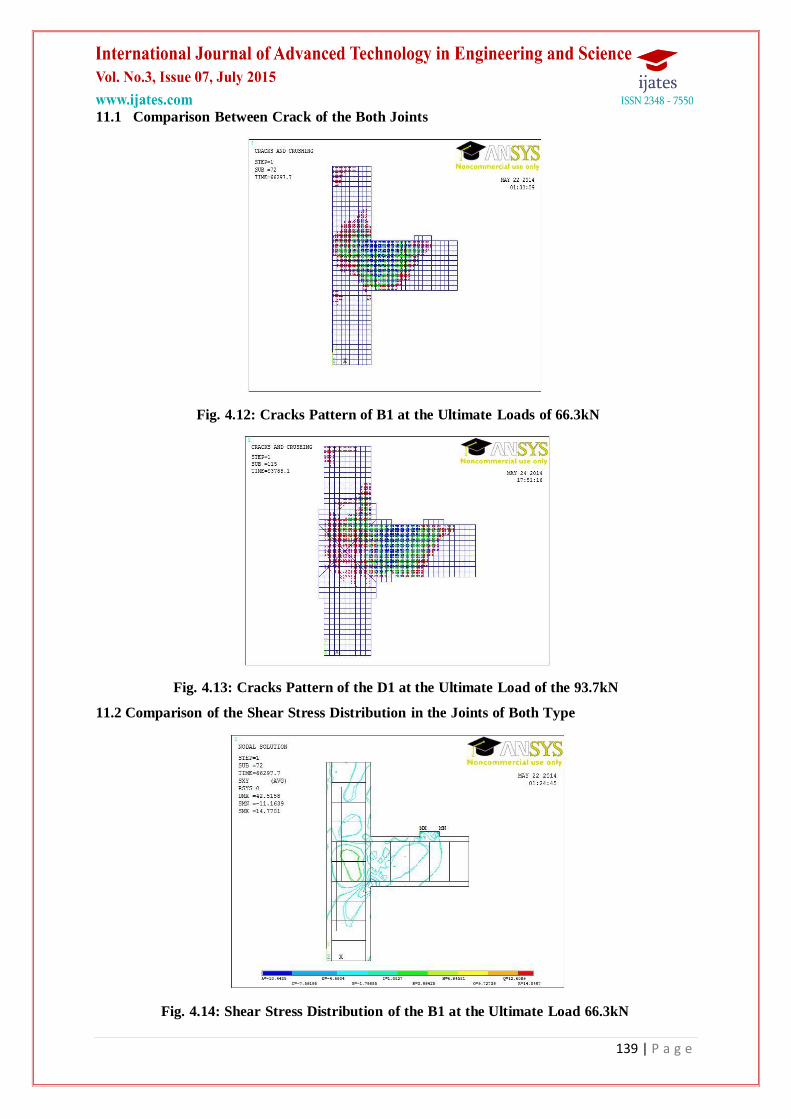
11.1 Comparison Between Crack of the Both Joints
Fig. 4.12: Cracks Pattern of B1 at the Ultimate Loads of 66.3kN
Fig. 4.13: Cracks Pattern of the D1 at the Ultimate Load of the 93.7kN
11.2 Comparison of the Shear Stress Distribution in the Joints of Both Type
Fig. 4.14: Shear Stress Distribution of the B1 at the Ultimate Load 66.3kN

140 | P a g e
Fig. 4.15: Shear Stress of the D1 at the Ultimate Loads of 93.7kN
By comparing the fig 4.14 and fig 4.15 it can be clearly stated that in B1 the shear force is more
concentrated in the joints. This proves the experimental test data of shear failure of joint. The fig
4.15 in which prestressing are being used clearly helped in putting the shear stress out of the joint core
and ultimately avoiding the shear failure of the joint.
11.3 Deflection Comparison of the Both Type of the Joints
Fig. 4.16: Deflection Profile of B1 at the Ultimate Load of 66.3kN

141 | P a g e
Fig. 4.17: Deflection Profile of D1 at the Ultimate Load of 93.7kN
Comparison of the fig 4.16 and fig 4.17 shows that the prestressing of the exterior beam- column
joint as proposed behave as more rigid than Dar (2011). The free end deflection of the B1 at 66.3kN is
38.3mm while in the D1 it is just 14.9 at 94.34kN.
11.4 Comparison of the Total Mechanical Shear Strain
Fig. 4.18: Shear Strain of the B1 at the Ultimate Loads of the 66.3kN

142 | P a g e
Fig. 4.19: Shear Stain of D1 at the Ultimate Loads of the 93.7kN
11.5 Summary of Comparisons
Comparison Summary of the Both Beam-Column Joints
Sl. No. Non-prestressed joints Pre-stressed joints
1. Crack location In the Joints Shifted to the Beam
2. Ultimate collapse load 66.3kN 93.7kN
3. Ultimate deflection 38.8 mm 145.8mm
XII. CONCLUSIONS
The following are point-wise conclusions which are being drawn from the proposed Exterior
Beam-Column Joints with prestressed joint core:
Maximum joint shear demand are located at lower portion of building, starting from second story joint
for both interior and exterior joints for the fixed support.
Maximum joint shear demand is located at first story joints for the hinge support condition for the
both interior and exterior joints.
The ratio of height of maximum shear to building height is coming out as 0.4 for the fixed support.
Shear forces demand increases with the increase of the Number of Story, Height of Story, Width of
Bays and Decreases with the Increase of Depth of Beams.
Grade of Concrete, Number of Bays and Size of Columns has no effect on the demand of the
shear forces in the beam-column joints.
Due to prestressing the Exterior Beam-Column Joints there has been increase in the shear strength of
the concrete in the joint core. But model for the calculation of the
shear strength of concrete in the prestressed beam-column joints has not been presented in the
present work.

143 | P a g e
Due to crossed prestressing with the rebar, strut and tie model has been invoked in the joints enhancing
the performance of the joints. With prestressed rebar acting as tie enhances the crack resistance in the
joint and consequently enhance the strut concrete performance which will act as better than without
stressed post crack condition.
Due to presence of the steel plate at the face of the Beam-Column joint, plastic hinge shifted at the edge
of the plate. This shifting of the hinge toward the centre of the beam leads to the less lateral
displacement at same given rotation at plastic hinge.
XIII. FUTURE SCOPE
Due to cross prestressing there is increase in the shear strength of the concrete in the joint core. A
model can be formulated to calculate the increase in shear strength of the joint core.
The above result clearly shows the increase in the performance of the joint due to cross-prestressing
which may leads to the decrease in the joint confinement reinforcement. Further a formulation can be
generated to calculate that how much reinforcement can be reduced due to this cross-prestressing.
IMPORTANT REFERENCES
Journals and articles
1. Rajagopal, S. and Prabavathy, S. (2013). Investigation on the Seismic behavior of the Exterior Beam-
column joint using T-type mechanical anchorage with hair-clip bar. Journal of King Saud University-
Engineering Sciences.
2. Thomas H.K.Kang and Mitra N. (2012). Prediction and performance of Exterior Beam-Column
Connections with the headed bars subjected to load reversal. Engineering Structures 41(2012) 209-217.
3. Pimanmas, P. and Chaimahawan, P. (2011). Cyclic shear resistance of Expanded Beam-Column Joint.
Procedia Engineering 14(2011) 1292-1299.
4. Pimanmas, P. and Chaimahawan, P. (2010). Shear Strength of Beam-Column Joint with Enlarged Joint
area. Engineering Structure. 32(2010) 2529-2545.
5. Pantazopoulou, S. J. and Bonacci, J. F. (1994). On earthquake resistant reinforced concrete frame
connections. Canadian Journal of Civil Engineering, 21, 307–328.
6. Rots, J. G. and Blaauwendraad. J. (1989). Crack models for concrete: Discrete or smeared? Fixed,
multidirectional or rotating? Heron, 34:1, 334–344.
7. Will, G. T., Uzumeri, S. M. and Sinha, S. K. (1972). Application of finite element method to analysis
of reinforced concrete beam-column joints. In Proceedings of Specialty Conference on Finite Element
Method in Civil Engineering, CSCE, EIC, Canada, 745–766.
8. Hegger, J., Sherif, A. and Roeser, W. (2004). Nonlinear Finite Element Analysis of Reinforced Concrete
Beam-Column Connections. ACI Structural Journal, 101:5, 601-614
9. Lowes, L. N., Altoontash, A. and Mitra, N. (2005). Closure to ―Modeling reinforced concrete beam-
column joints subjected to cyclic loading‖ by L. N. Lowes & A. Altoontash. Journal of Structural
Engineering, ASCE, 131:6, 993–994
10. Noguchi, H. (1981). Nonlinear finite element analysis of reinforced concrete beam-column joints. In IABSE
Colloquium, Delft, the Netherlands, 639–653.

144 | P a g e
11. LaFav/e, J. M. and Shin, M. (2005). Discussion of ―Modeling reinforced concrete beam-column joints
subjected to cyclic loading‖ by L. N. Lowes & A. Altoontash. Journal of Structural Engineering,
ASCE, 131:6, 992–993.
12. Baglin, P. S., and Scott, R. H. (2000). Finite element modeling of reinforced concrete beam- column
connections, ACI Structural Journal, 886-894.
13. Walker, S.G. (2001). Seismic Performance of Existing Reinforced Concrete Beam-column Joints. M.S.
Thesis. University of Washington, Seattle.
14. Alath, S. and Kunnath, S. K. (1995). ―Modeling Inelastic Shear Deformation in RC Beam- Column
Joints Engineering Mechanics: Proceedings of 10th Conference: University of Colorado at Boulder,
Boulder, Colorado. May 21-24, 1995. Vol. 2. New York: ASCE: 822-825.
15. Anderson, J.C. and Townsend, W.H. (1977). ―Models for RC Frames with Degrading Stiffness,‖ Journal
of the Structural Division, ASCE. 103 (ST12): 1433-1449.
16. Clyde, C., Pantelides, C.P. and Reaveley, L.D. (2000). ―Performance-Based Evaluation of Exterior
Reinforced Concrete Building Joints for Seismic Excitation.‖ Pacific Earthquake Engineering Research
Report, PEER 2000/05. Berkeley: University of California.
17. Durrani, A.J. and Wight, J.K. (1985). ―Behavior of Interior Beam-to-Column Connections under
Earthquake-Type Loading.‖ ACI Structural Journal 82 (3): 343-350.
18. El-Metwally, S.E. and Chen, W.F. (1988). ―Moment-Rotation Modeling of Reinforced Concrete Beam-
Column Connections.‖ ACI Structural Journal 85 (4): 384-394.
19. Elmorsi, M., Kianoush, M.R. and Tso, W.K. (2000). ―Modeling Bond-Slip Deformations in
Reinforced Concrete Beam-Column,‖ Canadian Journal of Civil Engineering 27: 490-505.
20. Fleury, F., Reynouard, J.M. and Merabet, O. (2000). ―Multicomponent Model of Reinforced Concrete
Joints for Cyclic Loading,‖ Journal of Engineering Mechanics ASCE 126 (8): 804-811.
21. Leon, R.T. (1990). ―Shear Strength and Hysteretic Behavior of Interior Beam-Column Joints.‖ ACI
Structural Journal 87 (1): 3-11.
22. Lowes, L.N. and Moehle, J.P. (1999). ―Evaluation and Retrofit of Beam-Column T-Joints in Older
Reinforced Concrete Bridge Structures.‖ ACI Structural Journal 96 (4): 519-532.
23. Mazzoni, S. and Moehle, J.P. (2001). ―Seismic Response of Beam-Column Joints in Double- Deck
Reinforced Concrete Bridge Frames.‖ ACI Structural Journal 98 (3): 259-269.
24. Meinheit, D.F. and Jirsa, J.O. (1977). ―The Shear Strength of Reinforced Concrete Beam-Column Joints.‖
CESRL Report No. 77-1. Austin: University of Texas.
25. Otani, S. (1974). ―Inelastic Analysis of RC Frame Structures,‖ Journal of the Structural Division, ASCE.
100 (ST7): 1433-1449.
26. Park, R. and Ruitong, D. (1988). ―A Comparison of the Behavior of Reinforced Concrete Beam- Column
Joints Designed for Ductility and Limited Ductility.‖ Bulletin of the New Zealand National
Society of Earthquake Engineering 21 (4): 255-278.
27. Hassan, W. M. (2011). Analytical and Experimental Assessment of Seismic Vulnerability of
Beam-Column Joints without Transverse Reinforcement in Concrete Buildings. PhD Dissertation,
University of California, Berkeley, California, USA.
28. Hassan, W. M., Park, S., Lopez, R., Mosalam, K. M., and Moehle, J. P. (2010). Seismic Response of

145 | P a g e
Older-Type Reinforced Concrete Corner Joints. Proceedings, 9th U.S. National Conference and 10th
Canadian Conference of Earthquake Engineering, Toronto, Canada, paper No. 1616.
29. Celik O. C., and Ellingwood, B. R. (2008). Modeling Beam-Column Joints in Fragility
Assessment of Gravity Load Designed Reinforced Concrete Frames. Journal of Earthquake Engineering.
12:357-381
30. Mitra, N. and Lowes, L. N. (2007). Evaluation, calibration and verification of a reinforced
concrete beam-column joint model. Journal of Structural Engineering, ASCE, 133:1, 105–120.
31. Mitra,N.(2008). Continuum model for interior beam-column connection regions. The 14th world
conference on earthquake engineering, Beijing, China.
32. Townsend WH, Hanson RD. Hysteresis loops for reinforced concrete beam–column connections.
In: Proceedings of 5th world conference on earthquake engineering. vol. 1. 1973. p. 1131–4.
33. Soleimani D, Popov EP, Bertero VV. Nonlinear beam model for RC frame analysis. In: 7th ASCE
conference on electronic computation. 1979.
34. Takeda T, Sozen MA, Nielsen NN. Reinforced concrete response to simulated earthquakes. J
StructEngDiv, ASCE 1970; 96(12):2257–73.
35. Fillipou FC, Popov EP, Bertero VV. Effects of bond deterioration on hysteretic behavior of reinforced
concrete joints. EERC report no. UCB/EERC-83/19.August 1983
36. Filippou FC, Issa A. Nonlinear analysis of reinforced concrete frames under cyclic load reversals. EERC
report UCB/EERC-88/12. 1988.
37. Kunnath SK, Hoffmann G, Reinhorn AM, Mander JB. Gravity-load-designed reinforced concrete
buildings—part I: seismic evaluation of existing construction.ACIStruct J 1995; 92(3):343–54.
38. Kunnath SK, Hoffmann G, Reinhorn AM, Mander JB. Gravity load-designed reinforced concrete
buildings—part II: evaluation of detailing enhancements. ACI Struct J 1995; 92(4):470–8.
39. Pampanin S, Magenes G, Carr A. Modelling of shear hinge mechanism in poorly detailed RC beam–
column joints. In: Proceedings of the FIB 2003 symposium. 2003.
40. Biddah A, Ghobarah A. Modelling of shear deformation and bond slip in reinforced concrete joints.
StructEngMech 1999; 7(4):413–32.
41. Ghobarah A, Biddah A. Dynamic analysis of reinforced concrete frames including joint shear
deformation. EngStruct 1999; 21:971–87.
42. Elmorsi M, Kianoush MR, Tso WK. Modeling bond-slip deformations in reinforced concrete beam–
column joints. Canad J CivEng 2000; 27:490–505.
43. Youssef M, Ghobarah A. Modelling of RC beam–column joints and structural walls. J EarthqEng
2001; 5(1):93–111.
44. Lowes LN, Altoontash A. Modeling reinforced-concrete beam–column joints subjected to cyclic
loading. J StructEng, ASCE 2003; 1686–97.
45. Altoontash A. Simulation and damage models for performance assessment of reinforced concrete
beam–column joints. Ph.D. dissertation. Stanford (CA): Department of Civil and Environment
Engineering. Stanford University; 2004.
46. Shin M, LaFave JM. Testing and modelling for cyclic joint shear deformations in RC beam–column
connections. In: Proceedings of the thirteenth world conference on earthquake engineering. Paper no.

146 | P a g e
0301. 2004
47. Vecchio FJ, Collins MP. The modified-compression field theory for reinforced concrete elements
subjected to shear. J American Concrete Institute 1986; 83(2):219–31.
48. Lowes LN, Mitra N, Altoontash A. A beam–column joint model for simulating the earthquake
response of reinforced concrete frames. Report no. PEER 2003/10. Pacific Earthquake Engineering
Research Center. 2004.
49. Nagai T, Kashiwazaki T, Noguchi H. Three dimensional nonlinear finite element analysis of RC
interior beam–column joints with ultra-high-strength materials under bi- directional load. Trans Japan
Concrete Institute 1996; 18.
50. Bing L, Yiming W, Tso-Chien P. Seismic behavior of non-seismically detailed Interior beam–wides
column joints—Part II: theoretical comparisons and analytical studies. ACI J 2003; 100(1).
51. Eligehausen R, Ožbolt J, Genesio G, Hoehler MS, Pampanin S. Three dimensional modelling of
poorly detailed RC frame joints. In: Proceedings of the annual NZSEE conference. 2006.
52. Sharma A, Reddy GR, Vaze KK, Ghosh AK, Kushwaha HS, Eligehausen R. Investigations on
inelastic behavior of non-seismically detailed reinforced Concrete beam–column joints under cyclic
excitations. BARC external report no. BARC/2008/E/017. 200
53. Sharma A, Eligehausen R; Reddy GR. A new model to simulate joint shear behavior of poorly detailed
beam-column connection in RC structures under seismic load. Part 1: exterior joints. Engineering
structures 33 (2011) 1034–1051
54. Ziyaeifar Mansour and Noguchi Hiroshi. A refined model for beam elements and beam- column joints.
Computers and structures 76 (2000) 551-564.
55. Seitaro Tajiri, Hitoshi Shiohara, Fumio Kusuhara. A new macro element of reinforced concrete
beam-column joint for Elasto-Plastic plane frame analysis. Paper No.674,Proceeding of the 8th US
National conference on earthquake engineering(2006) San Francisco, California, USA
56. Dar, M.A. (2011). Effect of Different Wrapping Techniques on Retrofitting of RC Beam- Column joints
using Ferro cement. www.dsapce.thapar.edu
57. Wolanski A. Flexural behavior of reinforced and prestressed concrete beams using finite element
analysis. Master thesis, Marquette University, Milwaukee, Wisconsin, 2004.
Books
58. Park, R. and Paulay, T. (1975). Reinforced Concrete Structures. New York: John Wiley & Sons.
59. Strang, Gilbert; Fix, George (1973). An Analysis of the Finite Element Method. Prentice Hall. ISBN 0-13-
032946-0.
60. George G. Penelis and Andreas J. Kappos (1997). Earthquake resistant concrete structure. Taylor and
Francis.
61. Eugenio Onate (2009); Structural analysis with the finite element method: linear static volume 1:
basic and solids; Springer
62. Zienkiewicz, O.C.; Taylor, R.L.; Zhu, J.Z. (2005). The Finite Element Method: Its Basis and
Fundamentals (Sixth Ed.). Butterworth-Heinemann. ISBN 0750663200.