Embed Size (px)
Citation preview
Tailor Made Concrete Structures – Walraven & Stoelhorst (eds)© 2008 Taylor & Francis Group, London, ISBN 978-0-415-47535-8
Shear design of FRC members with little or no conventional shearreinforcement
F. Minelli & G.A. PlizzariUniversity of Brescia, Department DICATA, Brescia, Italy
ABSTRACT: The present paper deals with some crucial design aspects of Fiber Reinforced Concrete (FRC)beams under shear loading, with or without conventional transverse reinforcement. It focuses on shear criticalbeams made of plain concrete or FRC.The influence of fibers on crack formation and development, failure mode,ductility and stiffness are herein investigated. A recent analytical proposal of the authors is further developed.Statements on the minimum shear reinforcement provided by steel fibers are derived and discussed. Finally,some preliminary results on the size effect issue of FRC members in shear and a design example are reported.
1 INTRODUCTION
In spite of the vast amount of experiments that havebeen conducted to assess the shear capacity of struc-tural concrete members, the behavior and design ofreinforced concrete (RC) elements under shear remainan area of much concern. Design codes are continu-ally changing and generally becoming more stringentso that structures that were designed several decadesago typically do not comply with the requirements ofcurrent codes.
Several proposals for predicting the shear capac-ity of beams without transverse reinforcement werepublished years by years: usually, they are empiricalformulations, designed to fit the limited set of sheartest results that are most familiar to the researchers.
It remains a pressing need to establish design andanalysis methods that provide realistic assessmentsof the strength, stiffness and ductility of structuralelements subjected to shear loading.
Adding structural (high modulus) fibers to the con-crete matrix demonstrated to be quite effective inreducing the brittleness associated with shear failure,as outlined by many researchers, among them Imamet al. (1995) and Khuntia et al. (1999).
In heavy precast industry, where high strength con-crete (HSC) is commonly adopted, diffused fiberreinforcement could be utilized to reduce or substituteconventional transverse reinforcement, with advan-tages in the production process and in the reductionof labor costs in placing and handling of rebars (Medaet al., 2005).
The present paper deals with some crucial designaspects of Fiber Reinforced Concrete (FRC) beamsunder shear loading, with or without conventionaltransverse reinforcement.
A recent analytical proposal developed in the Ph.D.thesis of Minelli (2005) and included in the FRCItalian Guidelines CNR-DT 204/2006 (2006) is fur-ther discussed and compared against more than 60experiments available in literature. Special emphasisis devoted to the actual resistance mechanism providedby fibers and, moreover, in the way is put into designguidelines.
Moreover, shear experiments on deep beams andan analytical formulation for the design of the mini-mum toughness of a FRC to satisfy the minimum shearreinforcement requirement are also given.
Final goal of the ongoing research at the Universityof Brescia is to provide a quite simple procedure whichcould allow engineers to become familiar with FRCand to incorporate them in the design formulations ofbuilding codes.
2 STRUCTURAL FIBERS: AN ALTERNATIVEFOR SHEAR REINFORCEMENT
A shear analytical model (Minelli, 2005) was devel-oped based on a quite simple adaptation of the currentformulation included in the current Eurocode 2 (EC2,2003) for shear in members without conventionaltransverse reinforcement. This formulation should beconsidered as a basis for including the effect of fibers,as the model is simple, well known, generally acceptedand utilized for design purposes.
Minelli et al. (2005) outlined that the addition ofa small amount of steel fibers (volume fraction Vfof 0.4–0.6%) significantly improves the structuralbehavior of members without transverse reinforce-ment: if FRC is tough enough, the collapse mechanismcan alter from shear (“block mechanism”) to flexure,
605

with a considerable increase in load bearing capac-ity and ductility. A brief summary of some interestingexperimental results follows.
Among the 47 shear tests carried out at the Uni-versity of Brescia since 2001 (most of them can befound in Minelli, 2005), the following discussion willfocus on those experiments conducted to assess theinfluence of the minimum shear reinforcement, repre-sented either by classical transverse reinforcement orsteel fibers, and the size effect in shear.
Two series of specimens are presented herein: thefirst refers to beams having a total depth of 500 mm(“Small Size Specimens”), while the second consistsof elements 1000 mm deep (“Large Size Specimens”).
Concerning the first set of experiments, five shear-critical beams loaded with a three point loading systemhaving a shear span-to-depth ratio of 2.5 (which isrecognized to be the most critical in terms of shearstrength; Kani, 1967) were tested. All beams had thesame geometry and were tested for analyzing theeffect of the addition of a randomly distributed fibrousreinforcement to concrete.
A beam depth of 500 mm was chosen, with a grosscover of 45 mm. The beam spanned 2280 mm, whilethe overall length of the specimen was 2400 mm.Two deformed longitudinal bars, having a diameter of24 mm, were added to each specimen, correspondingto a reinforcement ratio of 1.04%.
Deeper beams (Large Size Specimens) were castwith a total depth of 1000 mm, an effective depth of910 mm, a width of 200 mm and a span of 4550 mm(Figure 1). A three point loading scheme was chosenresulting in a span-to-depth ratio again of 2.5.The steelreinforcement (6φ20 mm rebars) was located in twoidentical bottom layers giving a reinforcing ratio of1.03%.
All smaller specimens were cast by using a normalstrength concrete (NSC), while two different seriesof larger beams were tested, the first one cast in thesame batch as the smaller beams, whereas the secondusing a high strength matrix (HSC). Table 1 reports thecomposition of the two different concrete batches.
One Small Specimens was cast without any trans-verse reinforcement (PC-50), two with the minimumamount of transverse reinforcement (MSR-50, withstirrups 2φ8@300 mm) as required by EC2 (2003),and two with 20 kg/m3 of steel fibers (FRC-50) hav-ing a length of 50 mm and a diameter of 1 mm (aspectratio l/φ = 50).
The fracture properties of FRC were determinedaccording to the Italian Standard (UNI 11039, 2003),which requires bending tests (4PBT) on small beamspecimens (150 × 150 × 600 mm).
The equivalent post-cracking strengths related tothe SLS and ULS were equal to feq(0−0.6) = 2.53 MPaand feq(0.6−3) = 2.50 MPa (UNI 11039, 2003),respectively.
Figure 1. Geometry of Large Size Specimen.
Table 1. Mechanical properties of concrete.
NSC HSC
Cement Content [kg/m3] 345 380Maximum Aggregate Size [mm] 20 20Plasticizer [l/m3] 5.2 3.8Compressive Cubic Strength [MPa] 25.7 55Elastic Modulus [GPa] 31 37
Three Large Size Specimens were cast for eachconcrete strength (NSC and HSC): the reference ele-ment (PC-100), the beam containing the minimumamount of shear reinforcement (MSR-100, with stir-rups 2φ8@650 mm) and the latter containing 20 kg/m3
of hooked steel fibers (FRC-100). Note that the nota-tion (1) PC refers to a beam cast with plain concrete;(2) FRC always indicates a beam with fibers as theonly shear reinforcement; (3) MSR refers to a beamwith minimum conventional shear reinforcement.
One should note that 20 kg/m3 corresponds to a vol-ume fraction very low (0,25%) that was accepted in thisexperimentation whose aim is the evaluation of steelfibers as a minimum transverse shear reinforcement.
Figure 2 and Figure 3 show the load-displacementcurves for the large size specimens, respectively forthe NSC series and HSC series.
Figure 4 exhibits the width of the main shear crackvs. the load for the HSC series. Note that the main shearcrack is the average of 6 measurement performed inboth shear spans (see Figure 4).
Differently form the small size specimens (Minelliet al., 2007), in larger beams the traditional shear rein-forcement turned out to be significantly more effectivethan steel fibers, both in terms of bearing capacity andductility. However, at service loads fibers gives bet-ter performance, compared to the MSR specimens,improving the tension stiffening effect and thereforereducing the displacement. Also cracks are fewer and
606
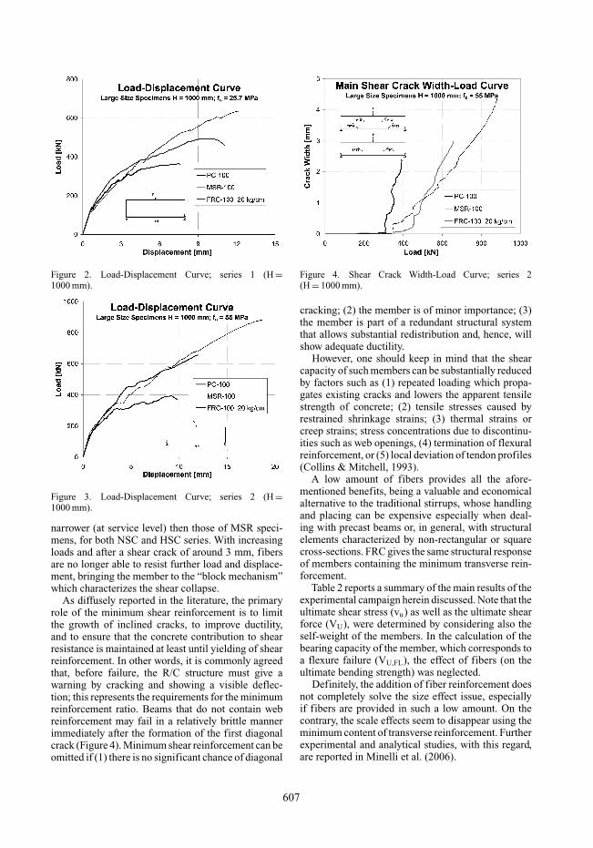
Figure 2. Load-Displacement Curve; series 1 (H =1000 mm).
Figure 3. Load-Displacement Curve; series 2 (H =1000 mm).
narrower (at service level) then those of MSR speci-mens, for both NSC and HSC series. With increasingloads and after a shear crack of around 3 mm, fibersare no longer able to resist further load and displace-ment, bringing the member to the “block mechanism”which characterizes the shear collapse.
As diffusely reported in the literature, the primaryrole of the minimum shear reinforcement is to limitthe growth of inclined cracks, to improve ductility,and to ensure that the concrete contribution to shearresistance is maintained at least until yielding of shearreinforcement. In other words, it is commonly agreedthat, before failure, the R/C structure must give awarning by cracking and showing a visible deflec-tion; this represents the requirements for the minimumreinforcement ratio. Beams that do not contain webreinforcement may fail in a relatively brittle mannerimmediately after the formation of the first diagonalcrack (Figure 4). Minimum shear reinforcement can beomitted if (1) there is no significant chance of diagonal
Figure 4. Shear Crack Width-Load Curve; series 2(H = 1000 mm).
cracking; (2) the member is of minor importance; (3)the member is part of a redundant structural systemthat allows substantial redistribution and, hence, willshow adequate ductility.
However, one should keep in mind that the shearcapacity of such members can be substantially reducedby factors such as (1) repeated loading which propa-gates existing cracks and lowers the apparent tensilestrength of concrete; (2) tensile stresses caused byrestrained shrinkage strains; (3) thermal strains orcreep strains; stress concentrations due to discontinu-ities such as web openings, (4) termination of flexuralreinforcement, or (5) local deviation of tendon profiles(Collins & Mitchell, 1993).
A low amount of fibers provides all the afore-mentioned benefits, being a valuable and economicalalternative to the traditional stirrups, whose handlingand placing can be expensive especially when deal-ing with precast beams or, in general, with structuralelements characterized by non-rectangular or squarecross-sections. FRC gives the same structural responseof members containing the minimum transverse rein-forcement.
Table 2 reports a summary of the main results of theexperimental campaign herein discussed. Note that theultimate shear stress (vu) as well as the ultimate shearforce (VU), were determined by considering also theself-weight of the members. In the calculation of thebearing capacity of the member, which corresponds toa flexure failure (VU,FL), the effect of fibers (on theultimate bending strength) was neglected.
Definitely, the addition of fiber reinforcement doesnot completely solve the size effect issue, especiallyif fibers are provided in such a low amount. On thecontrary, the scale effects seem to disappear using theminimum content of transverse reinforcement. Furtherexperimental and analytical studies, with this regard,are reported in Minelli et al. (2006).
607

Table 2. Summary of the main experimental values.
Pu vu vu/(fc)1/2 δu Vu/Vu,FLSpecimen [kN] [MPa] [−] [mm] [−]
PC-50 216 1.22 0.24 2.74 0.52MSR-50 1 346 1.93 0.38 9.33 0.82MSR-50 2 302 1.69 0.33 7.03 0.72FRC-50 1 388 2.16 0.43 10.95 0.92FRC-50 2 308 1.72 0.34 4.77 0.73
PC-100 NSC 365 1.07 0.21 7.60 0.43MSR-100 635 1.81 0.36 12.60 0.73FRC-100 494 1.42 0.28 11.05 0.57
PC-100 HSC 393 1.14 0.15 9.79 0.45MSR-100 880 2.48 0.33 18.62 0.99FRC-100 656 1.86 0.25 12.01 0.74
3 SHEAR STRENGTH OF FRC BEAMS
As above mentioned, the model proposed by Minelli(2005) aimed at including a performance parameterof FRC in the EC2 (2003) formulation for shear. Theperformance parameter is conventionally assumed asthe equivalent post-cracking strength defined in theItalian Standard UNI 11039 (2003). This parametercan be determined from fracture tests on small notchedbeams, as specified.
Since shear cracking in FRC members proved todevelop in a quite stable fashion, even for crack widthsof 3 mm (Figure 4), the equivalent strength related tothe ultimate limit state (feq(0.6−3) in UNI 11039 or fR4in EN 14651 (2005) can be considered. The ability offibers in controlling the second branch of the shear-critical crack even for big crack widths is due to theircapability of bridging the two faces of a crack. Bykeeping cracks stable, the shear capacity of membersconsiderably increases till, eventually, the full flexuralcapacity is attained.
The issue is now how to include a performanceparameter for FRC. The presence of fibers all overthe depth is relevant for the shear behavior, in thesame way as placing longitudinal rebars along thedepth of a member proved to be highly beneficialin terms of bearing capacity and overall ductility. Infact, Kuchma et al. (CEB Bulletin 237, 1997) demon-strated that, by adding three longitudinal layers ofrelatively low diameter bars over the depth of a spec-imen 1000 mm deep, the shear strength increased ofabout 50%, the ductility doubled and a well distributedcrack pattern formed, without an early localization ofany shear-critical crack.
Fibers act in providing a member with exactly thesame effect; therefore, it seems reasonable to model theshear contribution of fibers as a modifier of the longi-tudinal reinforcement ratio (as done also by Imam et al.(1995)) throughout a factor that includes the toughness
properties of fibers. The equation of EC2 for memberswithout web reinforcement is:
The toughness parameter (feq(0.6−3) in the presentwork) can be included, as above discussed, so that thefollowing relationship can be written:
where, besides all coefficients defined in EC2 (2003),0.30(fck )2/3 = fct , where fct is the tensile strength ofconcrete.
Since parameter feq(0.6−3) usually ranges between 1and 5 MPa, the increase in shear strength due to fiberreinforcement can become twice as much as that of themember without fibers. It can be concluded that theformulation proposed give reasonable values for mostpractical applications, and confirm the experimentalresults carried out at the University of Brescia. A com-parison between the proposed formulation against awide set of experimental results obtained within aBrite-Euram program (2002) was quite satisfactory(Minelli, 2005).
4 MINIMUM SHEAR REINFORCEMENT
The primary role of the minimum shear reinforcementis to limit the growth of inclined cracks, to improveductility, and to ensure that the concrete contributionto shear resistance is maintained at least until yield ofthe shear reinforcement.
The current codes require the minimum amountof transverse reinforcement, if necessary, to be ableto resist a portion of the shear force. The currentEC2 states that the minimum transverse reinforcementshould be designed as follows:
By arranging the above equation, one can find out theminimum transverse reinforcement percentage:
The same approach can be followed for FRC, byimposing that the minimum amount of shear reinforce-ment be carried by fibers only. The minimum FRCtoughness to satisfy minimum shear resistance can bedetermined by imposing that:
608
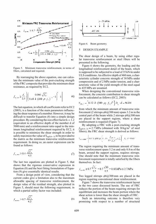
Figure 5. Minimum transverse reinforcement, in terms offibers, calculated and required.
By rearranging the above equation, one can calcu-late the minimum value of the post-cracking strengthof the FRC composite that provides the minimum shearresistance, as required by EC2.
The last equation, in which all coefficients refer to EC2(2003), is a function of the main parameters influenc-ing the shear response of a member. However, it may bedifficult to transfer Equation (8) into a simple designprocedure. By considering the size effect factor k = 1.2(equivalent to an effective depth of the member d of5000 mm) and a reinforcement ratio equal to the min-imum longitudinal reinforcement required by EC2, itis possible to minimize the shear strength in order tosafely maximize the value of feq(0,6−3) to be provided tothe matrix as the minimum transverse reinforcementrequirement. In doing so, an easier expression can befound as follows:
The last two equations are plotted in Figure 5, thatshows that the rigorous conservative expression inEquation (8) and the best fitting formulation of Equa-tion (9) give essentially identical results.
From a design point of view, considering that thecurrent codes give a limitation also to the maximumallowable spacing of transverse reinforcement, thedesign value of the residual strength, also plotted inFigure 5, should meet the following requirement, inwhich a partial safety factor was included:
Figure 6. Beam geometry.
5 DESIGN EXAMPLE
The shear design of a beam, by using either regu-lar transverse reinforcement or steel fibers will bepresented in the following.
Figure 6 shows the geometry, the loading and thelongitudinal reinforcement detail of the beam, whichis supposed to be subjected to a load of 35 kN/m underULS conditions.An effective depth of 460 mm, a char-acteristic cylinder concrete strength of 30 MPa undercompression and of 2 MPa under tension, and a char-acteristic value of the yield strength of the steel equalto 435 MPa are assumed.
When designing the conventional transverse rein-forcement, the concrete contribution to shear strengthcan be calculated as follows (EC2, 2003):
from which the minimum amount of transverse rein-forcement (2 stirrups φ6@300 mm) spans 3.2 m in thecentral part of the beam while 2 stirrups φ8@300 mmare placed in the support regions, where a shearreinforcement is required (Figure 7).
By adopting a FRC with a post-cracking strengthfeq(0.6−3) = 2.7 MPa (obtained with 30 kg/m3 of steelfibers), the FRC shear strength is derived as follows:
The region requiring the minimum amount of trans-verse reinforcement spans 5.2 m and only 0.8 m of thebeam, around the support regions, requires stirrups.One should note that the minimum transverse rein-forcement requirement is totally satisfied by the fibersthemselves. In fact:
Two legged stirrups φ6@300 mm are placed in theregion requiring conventional shear reinforcement.
Figure 7 shows the transverse reinforcement layoutin the two cases discussed herein. The use of FRCreduces the portion of the beam requiring stirrups forequilibrium and increases the beam portion where theshear action is lower than the shear strength of FRC.
Such an interesting outcome is therefore verypromising with respect to a number of structural
609
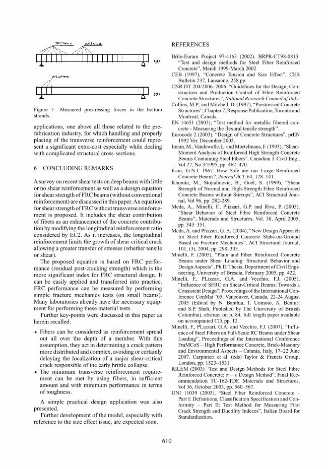
Figure 7. Measured prestressing forces in the bottomstrands.
applications, one above all those related to the pre-fabrication industry, for which handling and properlyplacing of the transverse reinforcement could repre-sent a significant extra-cost especially while dealingwith complicated structural cross-sections.
6 CONCLUDING REMARKS
A survey on recent shear tests on deep beams with littleor no shear reinforcement as well as a design equationfor shear strength of FRC beams (without conventionalreinforcement) are discussed in this paper.An equationfor shear strength of FRC without transverse reinforce-ment is proposed. It includes the shear contributionof fibers as an enhancement of the concrete contribu-tion by modifying the longitudinal reinforcement ratioconsidered by EC2. As it increases, the longitudinalreinforcement limits the growth of shear-critical crackallowing a greater transfer of stresses (whether tensileor shear).
The proposed equation is based on FRC perfor-mance (residual post-cracking strength) which is themore significant index for FRC structural design. Itcan be easily applied and transferred into practice.FRC performance can be measured by performingsimple fracture mechanics tests (on small beams).Many laboratories already have the necessary equip-ment for performing these material tests.
Further key-points were discussed in this paper asherein recalled:
• Fibers can be considered as reinforcement spreadout all over the depth of a member. With thisassumption, they act in determining a crack patternmore distributed and complex, avoiding or certainlydelaying the localization of a major shear-criticalcrack responsible of the early brittle collapse.
• The minimum transverse reinforcement require-ment can be met by using fibers, in sufficientamount and with minimum performance in termsof toughness.
A simple practical design application was alsopresented.
Further development of the model, especially withreference to the size effect issue, are expected soon.
REFERENCES
Brite-Euram Project 97-4163 (2002). BRPR-CT98-0813:“Test and design methods for Steel Fiber ReinforcedConcrete”, March 1999-March 2002
CEB (1997), “Concrete Tension and Size Effect”, CEBBulletin 237, Lausanne, 258 pp.
CNR DT 204/2006. 2006. “Guidelines for the Design, Con-struction and Production Control of Fibre ReinforcedConcrete Structures”, National Research Council of Italy.
Collins, M.P., and Mitchell, D. (1997), “Prestressed ConcreteStructures”, Chapter 7, Response Publication,Toronto andMontreal, Canada.
EN 14651 (2005); “Test method for metallic fibered con-crete - Measuring the flexural tensile strength”.
Eurocode 2 (2003), “Design of Concrete Structures”, prEN1992 Ver. December 2003.
Imam, M.,Vandewalle, L. and Mortelmans, F. (1995), “Shear-Moment Analysis of Reinforced High Strength ConcreteBeams Containing Steel Fibers”, Canadian J. Civil Eng.,Vol 22, No 3/1995, pp. 462–470.
Kani, G.N.J. 1967. How Safe are our Large ReinforcedConcrete Beams?. Journal ACI, 64, 128–141.
Khuntia, M., Stojadinovic, B., Goel, S. (1999), “ShearStrength of Normal and High-Strength Fibre ReinforcedConcrete Beams without Stirrups”, ACI Structural Jour-nal, Vol 96, pp. 282-289.
Meda, A., Minelli, F., Plizzari, G.P. and Riva, P. (2005),“Shear Behavior of Steel Fibre Reinforced ConcreteBeams”; Materials and Structures, Vol. 38, April 2005,pp. 343–351.
Meda, A. and Plizzari, G. A. (2004), “New Design Approachfor Steel Fiber Reinforced Concrete Slabs-on-GroundBased on Fracture Mechanics”, ACI Structural Journal,101, (3), 2004, pp. 298–303.
Minelli, F. (2005), “Plain and Fiber Reinforced ConcreteBeams under Shear Loading: Structural Behavior andDesign Aspects”, Ph.D. Thesis, Department of Civil Engi-neering, University of Brescia, February 2005, pp. 422.
Minelli, F., PLizzari, G.A. and Vecchio, F.J. (2005),“Influence of SFRC on Shear-Critical Beams: Towards aConsistent Design”; Proceedings of the International Con-ference ConMat ’05, Vancouver, Canada, 22-24 August2005 (Edited by N. Banthia, T. Uomoto, A. Benturtand S.P. Shah, Published by The University of BritishColumbia), abstract on p. 84, full length paper availableon accompanied CD, pp. 12.
Minelli, F., PLizzari, G.A. and Vecchio, F.J. (2007), “Influ-ence of Steel Fibers on Full-Scale RC Beams under ShearLoading”, Proceedings of the International ConferenceFraMCoS – High Performance Concrete, Brick-Masonryand Environmental Aspects – Catania, Italy, 17–22 June2007. Carpinteri et al. (eds) Taylor & Francis Group,London, pp. 1523–1531
RILEM (2003) “Test and Design Methods for Steel FibreReinforced Concrete; σ − ε Design Method”, Final Rec-ommendation TC-162-TDF, Materials and Structures,Vol 36, October 2003, pp. 560–567.
UNI 11039 (2003), “Steel Fiber Reinforced Concrete –Part I: Definitions, Classification Specification and Con-formity – Part II: Test Method for Measuring FirstCrack Strength and Ductility Indeces”, Italian Board forStandardization.
610