Embed Size (px)
Citation preview
Composites: Part A 81 (2016) 182–192
Contents lists available at ScienceDirect
Composites: Part A
journal homepage: www.elsevier .com/locate /composi tesa
Shear response of carbon fiber composite octet-truss lattice structures
http://dx.doi.org/10.1016/j.compositesa.2015.11.0151359-835X/� 2015 Elsevier Ltd. All rights reserved.
⇑ Corresponding author.E-mail address: [email protected] (L. Dong).
Liang Dong ⇑, Haydn WadleyDepartment of Materials Science and Engineering, University of Virginia, Charlottesville, VA 22903, United States
a r t i c l e i n f o
Article history:Received 23 July 2015Received in revised form 4 November 2015Accepted 7 November 2015Available online 14 November 2015
Keywords:A. Sandwich structuresA. Polymer-matrix composites (PMCs)B. Mechanical propertiesE. Assembly
a b s t r a c t
Ultralight three dimensional space filling octet-truss lattice structures have been fabricated from carbonfiber reinforced polymer (CFRP) laminates using a mechanical snap-fitting and adhesive bondingtechnique. The lattice structures moduli and strengths have been measured during (001) in-plane shearas a function of the lattice relative density (�q). Their strength was determined by the activation of twostrut failure modes: elastic buckling of the struts governed the response when �q < 5%, while delamina-tion failure controlled the strength for 16% > �q > 5%. The measured shear strengths are shown to be wellpredicted by micromechanics models based on the elastic buckling and delamination failure of the struts.Snap-fit CFRP octet-truss lattice structures with densities of 24–230 kg m�3 are found to have mechanicalproperties superior to polymer and metal foams, and are competitive with Balsa wood and recentlyreported Ti–6Al–4V octet-truss lattices. They provide new opportunities for ultra-lightweightmulti-axially loaded structures.
� 2015 Elsevier Ltd. All rights reserved.
1. Introduction
Cellular lattice structures have attracted considerable interestfor the cores of lightweight sandwich panels [1–3]. In thisapproach, two thin face sheets made from materials with highspecific stiffness and strength are widely separated by a low den-sity lattice core [4–6]. The mechanical performance of a sandwichpanel is governed by its geometry (face sheet thickness and coreheight) and by the mechanical properties of its faces and core withthe latter governed by the core topology and properties of thematerials used to make it. In addition to their significant bendresistance, some sandwich panel structures also provide substan-tial out of plane compressive strength [7–15], and have attractedinterest for mitigating the effects of impulsively applied loads[16–21].
Lattice topology core structures with pyramidal and tetrahedralcell topologies [3] have been developed to promote truss deforma-tion in a stretch dominated manner [22], whereupon the stiffnessand strength scale linearly with relative density, �q, of the latticestructure (the density of the lattice structure divided by that ofthe material from which it was made) [4,5,23]. The use of highspecific stiffness carbon fiber reinforced polymer (CFRP) laminatesto make sandwich panel structures using single layer pyramidallattice has been explored recently [11–14,24]. These studies indi-cate their mechanical properties are competitive with existing
materials and topologies. However, as the thickness of a core isincreased to improve the bending resistance of a sandwich panel,the distance of nodal connections between the core and the faces(which scale with depth for single unit cell thick cores) alsoincreases [9,18,25,26]. This then increases the susceptibility ofthe panel to face sheet wrinkling [27,28] and nodal failure [28]during panel bending. Furthermore, as the relative density of sucha lattice is decreased to enable more of the panel mass to be allo-cated to faces, the trusses become more slender resulting in failureby elastic buckling [29,30]. These considerations have led to aninterest in the multilayer lattice structures whose cell size can bedefined independently of the sandwich core thickness.
The octet-truss [31] lattice structure, Fig. 1 with face-centeredcubic symmetry, provides a method for filling 3-D space with astructurally efficient truss structure of arbitrary cell size. The jointconnectivity of the octet truss is 12, and the trusses of this spatiallyperiodic material deform by local stretching for all macroscopicloading states [32]. The effective mechanical properties of thestretch-dominated octet-truss lattice have been analyzed using amicromechanics approach [32], and shown to have an almost iso-tropic yield surface. When made from high specific strength mate-rials, the octet-truss lattice is a highly weight efficient, multiaxialstress supporting structure. Lightweight aluminum alloy structureshave been made by an investment casting [32] and by additivemanufacturing methods [33–35]. Wrought titanium alloyoctet-truss lattices have also been recently fabricated [36] via acombined snap-fit and brazing approach, and offer potential forelevated temperature aerospace applications.
Fig. 1. (a) An octet-truss lattice constructed by the 3D translation of the unit cell shown in (b). The unit cell of the octet-truss lattice is composed of a (red) center octahedralunit and 8 (gray) edge tetrahedral cells. (For interpretation of the references to color in this figure legend, the reader is referred to the web version of this article.)
Fig. 2. Schematic illustration of the internal structure of the as-received CFRPlaminate used to make the lattice. The laminate comprised 2 surface plies madefrom plain weave fabrics that sandwich 6 unidirectional plies of the same thickness
L. Dong, H. Wadley / Composites: Part A 81 (2016) 182–192 183
Carbon fiber composites (CFRP) have a higher specific strengthand stiffness than aluminum and titanium alloys, and are thereforea promising material for making stiff and potentially strong cellu-lar structures for ambient temperature, lightweight applications.The application of a simple ‘‘snap-fit” assembly method [10] forfabricating and joining the pyramidal trusses and intermediatefaces of an octet-truss cellular material made from CFRP laminateshas been recent described [14]. The compressive responses of theoctet-truss lattice in both its [001] and [100] directions were char-acterized as a function of the lattice relative density. However,sandwich panels are most widely used in situations where theyare subjected to significant bending; a loading mode in whichthe shear response of the core governs the panel’s mechanicalresponse [1,2]. Here, the in-plane shear of snap-fit CFRP octet-truss lattices has been experimentally investigated as a functionof the lattice relative density and their stiffness and strength com-pared to micromechanical predictions.
arranged as a [0/90/0]s layup. (For interpretation of the references to color in thisfigure legend, the reader is referred to the web version of this article.)
2. CFRP lattice fabrication
2.1. Composite laminate materials
CFRP laminates with a 0/90 architecture were procured fromMcMaster-Carr and used to make the octet-truss lattice structuresusing a snap-fit method. The laminate sheets had a thicknesst = 1.59 mm and had a 55% by volume carbon fibers. The carbonfibers have a Young’s modulus of 228 GPa (33 Msi) and were dis-persed in a vinyl ester matrix. The density of the laminate materialwas 1440 kg/m3. The laminate was comprised of 8 plies: the 2 sur-face plies were made from plain weave fabrics while the 6 unidi-rectional interior plies of the same thickness were laid up in a[0/90/0]s arrangement, Fig. 2. The plain weave fabric layers con-tained fibers oriented along the two in-plane axes, and once curedcould support flexural and tensile loads applied on multiple axes[20]. The woven laminates are also less sensitive to local damagecompared with unidirectional laminates, and reduced the suscep-tibility to delamination during cutting operations [20]. Laminatesheets with woven plies on the outer surfaces were thus selectedfor the present study based upon this manufacturing constraint:the need to minimize the risk of delamination failures during fab-rication and assembly of the lattice structures. Octet-truss latticesmade from laminates with quasi-isotropic stacking sequencewould be very interesting and a ripe area for future studies as itsimplifies analysis of the laminate responses.
Experimental [11,12,15] and more fundamental studies [37–40]have shown that the compressive strengths of woven laminates arelower than unidirectional laminates due to fiber waviness. It isnoted that the as-received laminate sheets contained two plain
weave fabrics, four 0� unidirectional plies and two 90� unidirec-tional plies. Such a microstructure indicates that the as-receivedlaminate sheets will be orthotropic rather than the transverselyisotropic material often encountered in the simpler 0/90 balancedlaminates.
The composite laminate materials were tested in uniaxial com-pression along the two unidirectional fiber directions in order todetermine the longitudinal and transverse compressive and tensilemoduli and strengths of the parent material used to manufacturethe octet-truss lattices. A nominal applied strain rate of 10�4 s�1
was employed in these tests. Unclamped compression tests wereconducted with stocky (to prevent elastic buckling) dog-boneshaped laminate specimens [14] compressed between two flat,parallel and rigid platens with no end clamping. Celanese compres-sion (CLC) tests were also conducted in which the longitudinalsplitting and delamination can be suppressed. The mechanicalproperties of the as-received CFRP laminate along both the longitu-dinal and transverse directions are summarized in Table 1. Thelaminate exhibited a substantial amount scattering in compressivestrength; this well-known phenomenon [41] has been attributed tothe complex distribution of damage zones (induced by internalflaws or stress concentrations) which create instabilities that pre-maturely trigger kink band formation.
The laminate compressive strengths differ in different loadingconditions due to different failure mechanisms: in CLC compres-sion, failure was controlled by plastic fiber micro-buckling,whereas the failure was dominated by delamination in unclampedcompression, as observed optically (Fig. 3(a) and (b)) and con-firmed by l-XCT analysis (Fig. 3(c) and (d)). The damage modes
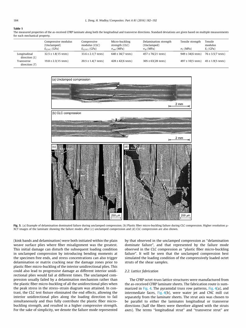
Table 1The measured properties of the as-received CFRP laminate along both the longitudinal and transverse directions. Standard deviations are given based on multiple measurementsfor each mechanical property.
Compressive modulus(Unclamped)
Compressivemodulus (CLC)
Micro-bucklingstrength (CLC)
Delamination strength(Unclamped)
Tensile strength Tensilemodulus
EC(UC) (GPa) EC(CLC) (GPa) rmb (MPa) rdl (MPa) rT (MPa) ET (GPa)
Longitudinaldirection (L)
32.5 ± 1.8(15 tests) 33.6 ± 2.1(7 tests) 640 ± 36(7 tests) 457 ± 76(21 tests) 949 ± 34(6 tests) 76 ± 3.5(7 tests)
Transversedirection (T)
19.8 ± 2.3(15 tests) 20.5 ± 1.4(7 tests) 428 ± 42(6 tests) 305 ± 63(28 tests) 497 ± 10(5 tests) 45 ± 1.9(5 tests)
Fig. 3. (a) Example of delamination dominated failure during unclamped compression. (b) Plastic fiber micro-buckling failure during CLC compression. Higher resolution l-XCT images of the laminate showing the failure modes after (c) unclamped compression and (d) CLC compression are also shown.
184 L. Dong, H. Wadley / Composites: Part A 81 (2016) 182–192
(kink bands and delamination) were both initiated within the plainweave surface plies where fiber misalignment was the greatest.This initial damage can disturb the subsequent loading conditionin unclamped compression by introducing bending moments atthe specimen free ends, and stress concentrations can also triggerdelamination or matrix cracking near the damage zones prior toplastic fiber micro-buckling of the interior unidirectional plies. Thiscould also lead to progressive damage as different interior unidi-rectional plies would fail at different times. The unclamped com-pression usually failed by a delamination mechanism rather thanthe plastic fiber micro-buckling of all the unidirectional plies whenthe peak stress in the stress–strain diagram was attained. In con-trast, the CLC test fixture eliminated the end effects, allowing theinterior unidirectional plies along the loading direction to failsimultaneously and thus fully contribute the plastic fiber micro-buckling strength, and resulted in a higher compressive strength.For the sake of simplicity, we denote the failure mode represented
by that observed in the unclamped compression as ‘‘delaminationdominate failure”, and that represented by the failure modeobserved in the CLC compression as ‘‘plastic fiber micro-bucklingfailure”. It will be seen that the unclamped compression bestsimulated the loading condition of the compressively loaded octetstruts of the shear samples.
2.2. Lattice fabrication
The CFRP octet-truss lattice structures were manufactured fromthe as-received CFRP laminate sheets. The fabrication route is sum-marized in Fig. 4. The pyramidal truss row patterns, Fig. 4(a), andintermediate faces, Fig. 4(b), were water jet and CNC mill cutseparately from the laminate sheets. The strut axis was chosen tobe parallel to either the laminates longitudinal or transversedirections (half the fibers were therefore aligned with the strutsaxes). The terms ‘‘longitudinal strut” and ‘‘transverse strut” are
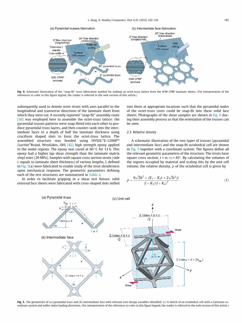
Fig. 4. Schematic illustration of the ‘‘snap-fit” truss fabrication method for making an octet-truss lattice from the 0/90 CFRP laminate sheets. (For interpretation of thereferences to color in this figure legend, the reader is referred to the web version of this article.)
L. Dong, H. Wadley / Composites: Part A 81 (2016) 182–192 185
subsequently used to denote octet struts with axes parallel to thelongitudinal and transverse directions of the laminate sheet fromwhich they were cut. A recently reported ‘‘snap-fit” assembly route[36] was employed here to assemble the octet-truss lattice: thepyramidal trusses patterns were snap-fitted into each other to pro-duce pyramidal truss layers, and then counter-sunk into the inter-mediate faces to a depth of half the laminate thickness usingcruciform shaped slots to form the octet-truss lattice. Theassembled structure was bonded using HYSOL�E-120HPTM
(Loctite�Brand, Westlakes, OH) [42] high strength epoxy appliedto the nodal regions. The epoxy was cured at 60 �C for 12 h. Thisepoxy had a higher lap shear strength than the laminate matrixvinyl ester (20 MPa). Samples with square cross section struts (sidet, equals to laminate sheet thickness) of various lengths, l, definedin Fig. 5(a) were fabricated to enable study of the strut slendernessupon mechanical response. The geometric parameters definingeach of the test structures are summarized in Table 2.
In order to facilitate gripping in a shear test fixture, solidexternal face sheets were fabricated with cross-shaped slots milled
Fig. 5. The geometries of (a) pyramidal truss and (b) intermediate face with relevant coordinate system and miller index loading directions. (For interpretation of the references
into them at appropriate locations such that the pyramidal nodesof the octet-truss cores could be snap-fit into these solid facesheets. Photographs of the shear samples are shown in Fig. 6 dur-ing their assembly process so that the orientation of the trusses canbe seen.
2.3. Relative density
A schematic illustration of the two types of trusses (pyramidaland intermediate face) and the snap-fit octahedral cell are shownin Fig. 5 together with a coordinate system. The figures define allthe relevant geometric parameters of the structure. The struts havesquare cross section, t = w, x = 45�. By calculating the volumes ofthe regions occupied by material and scaling this by the unit cellvolume, the relative density, �q of the octahedral cell is given by
�q ¼ 6ffiffiffi2
plt2 þ ðK1 � K2t þ 2
ffiffiffi2
pt2Þt
ðlþ K3Þðlþ K4Þ2ð1Þ
re design variables identified. (c) A sketch of an octahedral cell with a Cartesian co-to color in this figure legend, the reader is referred to the web version of this article.)
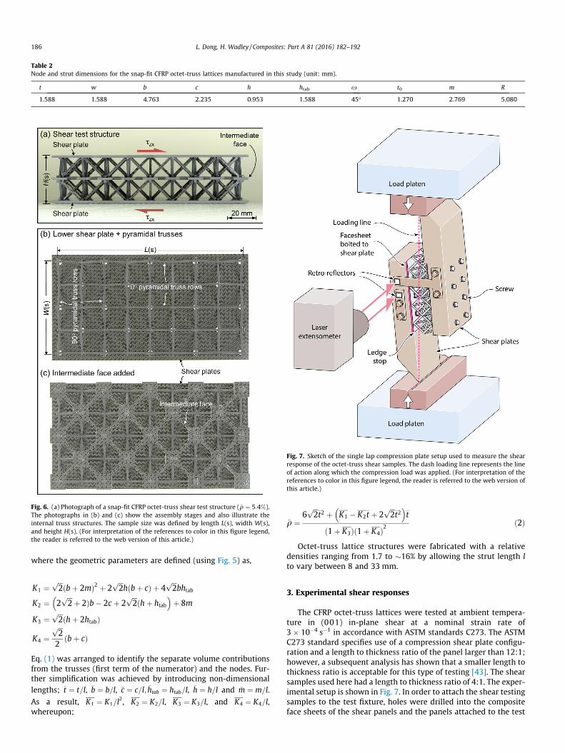
Table 2Node and strut dimensions for the snap-fit CFRP octet-truss lattices manufactured in this study (unit: mm).
t w b c h htab x t0 m R
1.588 1.588 4.763 2.235 0.953 1.588 45� 1.270 2.769 5.080
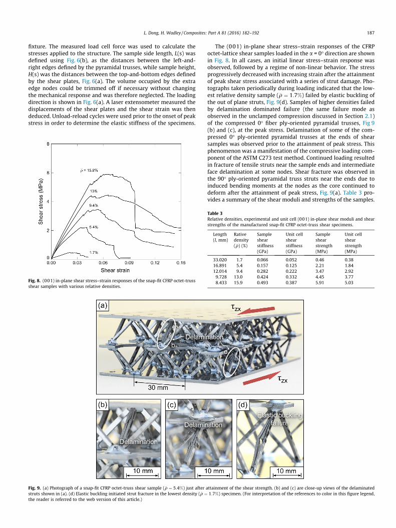
Fig. 6. (a) Photograph of a snap-fit CFRP octet-truss shear test structure (�q ¼ 5:4%).The photographs in (b) and (c) show the assembly stages and also illustrate theinternal truss structures. The sample size was defined by length L(s), width W(s),and height H(s). (For interpretation of the references to color in this figure legend,the reader is referred to the web version of this article.)
Fig. 7. Sketch of the single lap compression plate setup used to measure the shearresponse of the octet-truss shear samples. The dash loading line represents the lineof action along which the compression load was applied. (For interpretation of thereferences to color in this figure legend, the reader is referred to the web version ofthis article.)
186 L. Dong, H. Wadley / Composites: Part A 81 (2016) 182–192
where the geometric parameters are defined (using Fig. 5) as,
K1 ¼ffiffiffi2
pðbþ 2mÞ2 þ 2
ffiffiffi2
phðbþ cÞ þ 4
ffiffiffi2
pbhtab
K2 ¼ 2ffiffiffi2
pþ 2Þb� 2c þ 2
ffiffiffi2
pðhþ htab
� �þ 8m
K3 ¼ffiffiffi2
pðhþ 2htabÞ
K4 ¼ffiffiffi2
p
2ðbþ cÞ
Eq. (1) was arranged to identify the separate volume contributionsfrom the trusses (first term of the numerator) and the nodes. Fur-ther simplification was achieved by introducing non-dimensionallengths; �t ¼ t=l, �b ¼ b=l, �c ¼ c=l; �htab ¼ htab=l, �h ¼ h=l and �m ¼ m=l.
As a result, K1 ¼ K1=l2, K2 ¼ K2=l, K3 ¼ K3=l, and K4 ¼ K4=l,
whereupon;
�q ¼6
ffiffiffi2
p�t2 þ K1 � K2�t þ 2
ffiffiffi2
p�t2
� ��t
ð1þ K3Þð1þ K4Þ2ð2Þ
Octet-truss lattice structures were fabricated with a relativedensities ranging from 1.7 to �16% by allowing the strut length lto vary between 8 and 33 mm.
3. Experimental shear responses
The CFRP octet-truss lattices were tested at ambient tempera-ture in (001) in-plane shear at a nominal strain rate of3 � 10�4 s�1 in accordance with ASTM standards C273. The ASTMC273 standard specifies use of a compression shear plate configu-ration and a length to thickness ratio of the panel larger than 12:1;however, a subsequent analysis has shown that a smaller length tothickness ratio is acceptable for this type of testing [43]. The shearsamples used here had a length to thickness ratio of 4:1. The exper-imental setup is shown in Fig. 7. In order to attach the shear testingsamples to the test fixture, holes were drilled into the compositeface sheets of the shear panels and the panels attached to the test
L. Dong, H. Wadley / Composites: Part A 81 (2016) 182–192 187
fixture. The measured load cell force was used to calculate thestresses applied to the structure. The sample side length, L(s) wasdefined using Fig. 6(b), as the distances between the left-and-right edges defined by the pyramidal trusses, while sample height,H(s) was the distances between the top-and-bottom edges definedby the shear plates, Fig. 6(a). The volume occupied by the extraedge nodes could be trimmed off if necessary without changingthe mechanical response and was therefore neglected. The loadingdirection is shown in Fig. 6(a). A laser extensometer measured thedisplacements of the shear plates and the shear strain was thendeduced. Unload-reload cycles were used prior to the onset of peakstress in order to determine the elastic stiffness of the specimens.
Fig. 8. (001) in-plane shear stress–strain responses of the snap-fit CFRP octet-trussshear samples with various relative densities.
Fig. 9. (a) Photograph of a snap-fit CFRP octet-truss shear sample (�q ¼ 5:4%) just afterstruts shown in (a). (d) Elastic buckling initiated strut fracture in the lowest density (�q ¼the reader is referred to the web version of this article.)
The (001) in-plane shear stress–strain responses of the CFRPoctet-lattice shear samples loaded in the a = 0� direction are shownin Fig. 8. In all cases, an initial linear stress–strain response wasobserved, followed by a regime of non-linear behavior. The stressprogressively decreased with increasing strain after the attainmentof peak shear stress associated with a series of strut damage. Pho-tographs taken periodically during loading indicated that the low-est relative density sample (�q ¼ 1:7%) failed by elastic buckling ofthe out of plane struts, Fig. 9(d). Samples of higher densities failedby delamination dominated failure (the same failure mode asobserved in the unclamped compression discussed in Section 2.1)of the compressed 0� fiber ply-oriented pyramidal trusses, Fig 9(b) and (c), at the peak stress. Delamination of some of the com-pressed 0� ply-oriented pyramidal trusses at the ends of shearsamples was observed prior to the attainment of peak stress. Thisphenomenon was a manifestation of the compressive loading com-ponent of the ASTM C273 test method. Continued loading resultedin fracture of tensile struts near the sample ends and intermediateface delamination at some nodes. Shear fracture was observed inthe 90� ply-oriented pyramidal truss struts near the ends due toinduced bending moments at the nodes as the core continued todeform after the attainment of peak stress, Fig. 9(a). Table 3 pro-vides a summary of the shear moduli and strengths of the samples.
attainment of the shear strength. (b) and (c) are close-up views of the delaminated1:7%) specimen. (For interpretation of the references to color in this figure legend,
Table 3Relative densities, experimental and unit cell (001) in-plane shear moduli and shearstrengths of the manufactured snap-fit CFRP octet-truss shear specimens.
Length(l, mm)
Rativedensity(�q) (%)
Sampleshearstiffness(GPa)
Unit cellshearstiffness(GPa)
Sampleshearstrength(MPa)
Unit cellshearstrength(MPa)
33.020 1.7 0.066 0.052 0.46 0.3816.891 5.4 0.157 0.125 2.21 1.8412.014 9.4 0.282 0.222 3.47 2.929.728 13.0 0.424 0.332 4.45 3.778.433 15.9 0.493 0.387 5.91 5.03
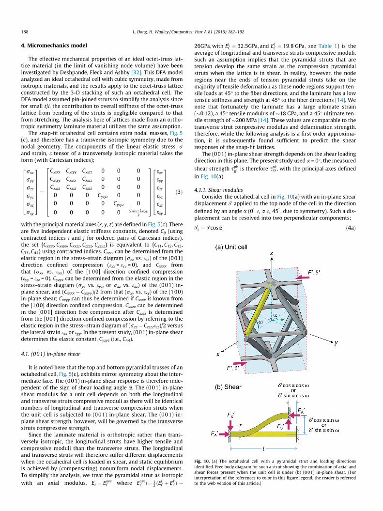
Fig. 10. (a) The octahedral cell with a pyramidal strut and loading directionsidentified. Free body diagram for such a strut showing the combination of axial andshear forces present when the unit cell is under (b) (001) in-plane shear. (Forinterpretation of the references to color in this figure legend, the reader is referredto the web version of this article.)
188 L. Dong, H. Wadley / Composites: Part A 81 (2016) 182–192
4. Micromechanics model
The effective mechanical properties of an ideal octet-truss lat-tice material (in the limit of vanishing node volume) have beeninvestigated by Deshpande, Fleck and Ashby [32]. This DFA modelanalyzed an ideal octahedral cell with cubic symmetry, made fromisotropic materials, and the results apply to the octet-truss latticeconstructed by the 3-D stacking of such an octahedral cell. TheDFA model assumed pin-joined struts to simplify the analysis sincefor small t/l, the contribution to overall stiffness of the octet-trusslattice from bending of the struts is negligible compared to thatfrom stretching. The analysis here of lattices made from an ortho-tropic symmetry laminate material utilizes the same assumption.
The snap-fit octahedral cell contains extra nodal masses, Fig. 5(c), and therefore has a transverse isotropic symmetry due to thenodal geometry. The components of the linear elastic stress, rand strain, e tensor of a transversely isotropic material takes theform (with Cartesian indices);
rxx
ryy
rzz
ryz
rxz
rxy
2666666664
3777777775¼
Cxxxx Cxxyy Cxxzz 0 0 0Cxxyy Cxxxx Cxxzz 0 0 0Cxxzz Cxxzz Czzzz 0 0 00 0 0 Cyzyz 0 00 0 0 0 Cyzyz 0
0 0 0 0 0 Cxxxx�Cxxyy
2
26666666664
37777777775
exxeyyezzeyzexzexy
2666666664
3777777775
ð3Þ
with the principalmaterial axes (x, y, z) are defined in Fig. 5(c). Thereare five independent elastic stiffness constants, denoted Cij (usingcontracted indices i and j for ordered pairs of Cartesian indices),the set {Cxxxx, Cxxyy, Cxxzz, Czzzz, Cyzyz} is equivalent to {C11, C12, C13,C33, C44} using contracted indices. Czzzz can be determined from theelastic region in the stress–strain diagram (rzz vs. ezz) of the [001]direction confined compression (exx = eyy = 0), and Cxxxx fromthat (rxx vs. exx) of the [100] direction confined compression(eyy = ezz = 0). Cyzyz can be determined from the elastic region in thestress–strain diagram (ryz vs. eyz, or rxz vs. exz) of the (001) in-plane shear, and (Cxxxx � Cxxyy)/2 from that (rxy vs. exy) of the (100)in-plane shear; Cxxyy can thus be determined if Cxxxx is known fromthe [100] direction confined compression. Cxxzz can be determinedin the [001] direction free compression after Czzzz is determinedfrom the [001] direction confined compression by referring to theelastic region in the stress–strain diagram of (rzz � Czzzzezz)/2 versusthe lateral strain exx or eyy. In the present study, (001) in-plane sheardetermines the elastic constant, Cyzyz (i.e., C44).
4.1. (001) in-plane shear
It is noted here that the top and bottom pyramidal trusses of anoctahedral cell, Fig. 5(c), exhibits mirror symmetry about the inter-mediate face. The (001) in-plane shear response is therefore inde-pendent of the sign of shear loading angle a. The (001) in-planeshear modulus for a unit cell depends on both the longitudinaland transverse struts compressive moduli as there will be identicalnumbers of longitudinal and transverse compression struts whenthe unit cell is subjected to (001) in-plane shear. The (001) in-plane shear strength, however, will be governed by the transversestruts compressive strength.
Since the laminate material is orthotropic rather than trans-versely isotropic, the longitudinal struts have higher tensile andcompressive moduli than the transverse struts. The longitudinaland transverse struts will therefore suffer different displacementswhen the octahedral cell is loaded in shear, and static equilibriumis achieved by (compensating) nonuniform nodal displacements.To simplify the analysis, we treat the pyramidal strut as isotropicwith an axial modulus, Es ¼ Eave
C where EaveC ð¼ 1
2 ðELC þ ET
CÞ �
26GPa;with ELC ¼ 32:5GPa; and ET
C ¼ 19:8 GPa; see Table 1) is theaverage of longitudinal and transverse struts compressive moduli.Such an assumption implies that the pyramidal struts that aretension develop the same strain as the compression pyramidalstruts when the lattice is in shear. In reality, however, the noderegions near the ends of tension pyramidal struts take on themajority of tensile deformation as these node regions support ten-sile loads at 45� to the fiber directions, and the laminate has a lowtensile stiffness and strength at 45� to the fiber directions [14]. Wenote that fortunately the laminate has a large ultimate strain(�0.12), a 45� tensile modulus of �18 GPa, and a 45� ultimate ten-sile strength of �200 MPa [14]. These values are comparable to thetransverse strut compressive modulus and delamination strength.Therefore, while the following analysis is a first order approxima-tion, it is subsequently found sufficient to predict the shearresponses of the snap-fit lattices.
The (001) in-plane shear strength depends on the shear loadingdirection in this plane. The present study used a = 0�, the measured
shear strength spk0� is therefore spkzx, with the principal axes defined
in Fig. 10(a).
4.1.1. Shear modulusConsider the octahedral cell in Fig. 10(a) with an in-plane shear
displacement d0 applied to the top node of the cell in the directiondefined by an angle a (0
� 6 a 6 45�, due to symmetry). Such a dis-
placement can be resolved into two perpendicular components;
d01 ¼ d0cosa ð4aÞ
L. Dong, H. Wadley / Composites: Part A 81 (2016) 182–192 189
and
d02 ¼ d0sina ð4bÞFig. 10(b) shows the free body diagram of the edge clamped
strut highlighted in Fig. 10(a) with length l and side t when theoctahedral cell is in shear. Symmetry dictates that displacementsand rotations of nodes apart from the top and bottom shown inFig. 10(a) are constrained. The axial and shear displacementsapplied to the strut within the plane parallel to the d01 direction(i.e. x direction) are;
d0a ¼ d01cosx ð5aÞ
and
d0s ¼ d01sinx ð5bÞ
with such a strut subjected to either compression or tensiondisplacement. From beam theory, the axial and shear forces in sucha strut are given by
F 0A ¼ Eave
C t2d01 cosx
lð6aÞ
and
F 0S ¼
12EaveC Id01 sinx
l3ð6bÞ
The total force applied along the d01 direction of a unit cell is
F 01 ¼ 2ðF 0
A cosxþ F 0S sinxÞ ¼ Eave
C t2d01l
1þ tl
� �2" #
ð7aÞ
The force applied along the d02 direction is;
F 02 ¼ 2ðF 0
A cosxþ F 0S sinxÞ ¼ Eave
C t2d02l
1þ tl
� �2" #
ð7bÞ
It is noted that Eq. (7) was derived assuming fixed-end (built-in)struts (k = 2); for pin-joined struts (k = 1), the contribution to thestiffness by bending of the struts is negligible, and the (t/l)2 terms(i.e., F 0
S terms) in Eq. (7) disappear. The total shear force, F0, appliedon the unit cell is then
F 0 ¼ffiffiffiffiffiffiffiffiffiffiffiffiffiffiffiffiffiffiffiffiffiffiffiffiffiffiffiðF 0
1Þ2 þ ðF 02Þ2
q¼ Eave
C t2d0
lð8Þ
The total shear stress applied to the octahedral cell is thus
s ¼ F 0
A½001�¼ Eave
C t2d0
A½001�lð9Þ
The shear strain
c ¼ 2d0
H½001�ð10Þ
Therefore, the shear modulus of the octahedral cell is
G ¼ sc¼ t2H½001�
2A½001�lEaveC ð11Þ
If we define Es ¼ EaveC (26 GPa), Eq. (11) can be expressed in the
form of relative shear modulus;
GEs
¼ t2H½001�2A½001�l
¼ KGt2H½001�lA½001�
ð12Þ
with KG ¼ 12.
4.1.2. Shear strengthEq. (9) represents the total shear stress applied to the unit cell
during (001) in-plane shear. The axial stress, rA, in a pyramidalstrut is given by
rA ¼ EaveC d0cosaffiffiffi
2p
lð13Þ
Therefore, the (001) in-plane shear stress applied to theoctahedral cell, s, can be expressed in terms of the axial stress, rA;
s ¼ rA
ffiffiffi2
pt2
Acosað14Þ
A pyramidal strut can support compressive load until its col-lapse strength rc is achieved. Therefore, the octahedral cell shearstrength is given by
spk ¼ rc
ffiffiffi2
pt2
Acosað15Þ
This shear strength depends upon the specific failure mecha-nism (elastic buckling, delamination or plastic fiber micro-buckling) of the composite struts, and is obtained by replacing rc
in Eq. (15) with the corresponding compressive strength of thecomposite strut. We note that since the polymer matrices of fibercomposites used here have quite low shear strengths, elastic fibermicro-buckling is not an operative failure mode and has not beenconsidered in the collapse analysis below [44]. A compressed CFRPstrut can therefore collapse by either (i) elastic buckling, (ii) delam-ination or (iii) plastic fiber micro-buckling.
At low densities, struts are slender enough to collapse by elasticbuckling. The compressive strength of the lattice can be obtainedby replacing, rc in Eq. (15), with the elastic buckling stress, rE
for a solid strut with square cross section of side t;
rE ¼ k2p2EaveC
12tl
� �2
ð16Þ
The factor k is determined by the end conditions of the bucklingstruts. The pin-jointed k = 1 condition is assumed here for consis-tency with the DFA model [32].
For a stubby composite strut in compression, the compressiveloads accentuate shear stresses developed around initial defectssuch as misaligned or wavy fibers, matrix pores, partial delamina-tions, or residual stresses, leading to the formation of damagezones which propagate at an inclined angle to the loading direction[41]. For a matrix with low shear strength, delamination at theinter-ply interface can be initiated within such damage zones[41]. The lattice strength controlled by strut delamination isobtained by replacing rc in Eq. (15) with the measured delamina-tion strength, rdl. The lattice strength depends on the strut withhighest flaw density or stress concentration. Therefore, a conserva-tive transverse compressive strength of the laminate material gov-erned by delamination (rT
dlðminÞ ¼ 240 MPa, Table 1) was used forthe model predictions.
For a stubby composite strut with a strong matrix shearstrength, the interface debonding can be prevented after the for-mation of damage zones. The composite struts then fail by plasticfiber micro-buckling once the matrix plastically yields. The plasticfiber micro-buckling stress, rmb, is given by the CLC compressionmeasurement. The (001) in-plane shear strengths governed byplastic fiber micro-buckling failure of octet struts are given byreplacing rc in Eq. (15) with a conservative transverse compressivestrength of the laminate material governed by plastic fiber micro-buckling failure,rT
mbðminÞ ¼ 386 MPa (Table 1).If we define rs ¼ rave
mb ðravemb ¼ 1
2 ðrLmb þ rT
mbÞ � 535 MPa, Table 1),Eq. (15) can be expressed in the form of relative shear strength as
190 L. Dong, H. Wadley / Composites: Part A 81 (2016) 182–192
spkrs
¼ffiffiffi2
pt2
ravemb cos a
rc
A¼ Ks
t2rc
Að17Þ
where Ks is a constant ¼ffiffi2
pravemb
cos a.
5. Discussion
The experimentally measured shear moduli and strengths of theoctet-truss lattices increased approximately linearly with latticerelative density, Table 3. However, the manufactured samples haveextra edge struts that belong to the unit cells of a larger area sam-ple. These edge struts of partial unit cells contribute both stiffnessand strength to the samples mechanical response. In order to com-pare experimental data and model predictions, it is therefore nec-essary to adjust the measured properties to account for this edgeeffect. If it is assumed the edge struts of adjacent cells behave inthe same manner as their inner strut counterparts, the total forcerequired to deform the counterpart lattice without redundant edgestruts can be shown (by taking the ratio of the number of strutsthat contribute stiffness/strength in lattices without extra edge
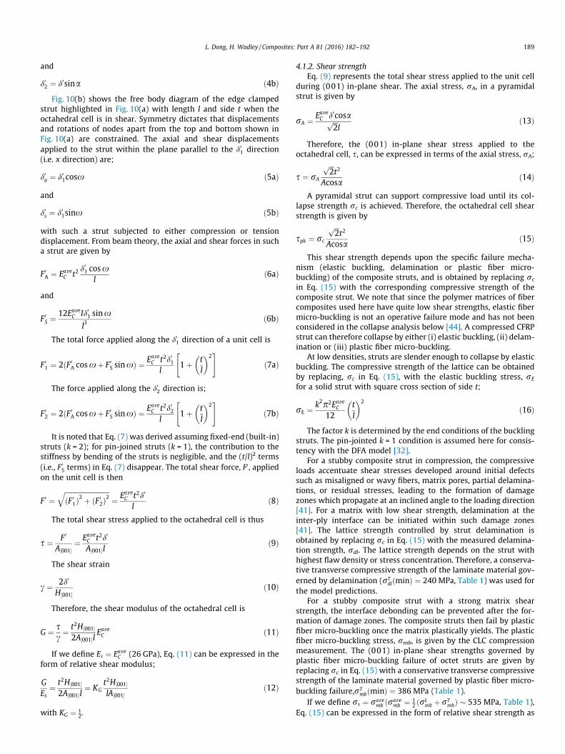
Fig. 11. Comparisons between measured (symbols) and predicted (001) in-planerelative shear moduli (a) and strengths (b) of the snap-fit CFRP octahedral cells as afunction of the relative density. Error bars represent the maximum and minimumvalues obtained from 3 separate measurements. (For interpretation of thereferences to color in this figure legend, the reader is referred to the web versionof this article.)
struts to the total number of struts in the tested samples) to be4/5 that of the lattice samples actually tested. The strength of a lat-tice without extra edge struts is then given by this applied forcedivided by its cross-sectional area, and is subsequently defined asthe unit cell strength; the unit cell stiffness is obtained as thisstress divided by the imposed strain. It is noted here that the man-ufactured samples have a height of H(s) = H + t, where H is theoctahedral cell height (as shown in Fig. 5(c), H = 2(l sinx + h+ 2htab)).
The relative shear moduli and strengths deduced from the mea-surements are plotted against the relative density, �q, in Fig. 11(a) and (b). The relative moduli were obtained by normalizing theunit cell measurement by the average compressive modulus of thesolid laminate, Es ¼ Eave
C � 26 GPa and unit cell strength by plasticfiber micro-buckling failure stress, rs ¼ rave
mb (535 MPa) of the solidlaminatematerial. Themodel predictions are also plotted on the fig-ures, and can be seen to agree well with the experimental data. Thedelamination and plastic fiber micro-buckling models used conser-vative transverse compressive strengths, rT
dlðminÞ ¼ 240 MPa andrT
mbðminÞ ¼ 386 MPa, of the laminatematerial for predictions,whilethe average compressive modulus Eave
C � 26 GPa was used for theelastic buckling strength predictions.
The relative shear strength is predicted to at �q � 0:054 toundergo a change of failure mode from elastic buckling to delam-ination of the compression struts. This prediction agreed well withmeasurements where at low densities failure occurred by elasticbuckling at near �q ¼ 0:054, transitioned to the delamination mode.The plastic fiber micro-buckling failure mode for the struts was notactivated (a consequence of insufficient nodal constraint), and thelattice strength never attained plastic fiber micro-buckling modelpredictions.
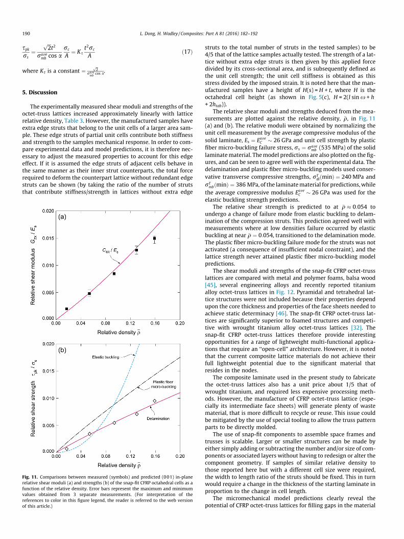
The shear moduli and strengths of the snap-fit CFRP octet-trusslattices are compared with metal and polymer foams, balsa wood[45], several engineering alloys and recently reported titaniumalloy octet-truss lattices in Fig. 12. Pyramidal and tetrahedral lat-tice structures were not included because their properties dependupon the core thickness and properties of the face sheets needed toachieve static determinacy [46]. The snap-fit CFRP octet-truss lat-tices are significantly superior to foamed structures and competi-tive with wrought titanium alloy octet-truss lattices [32]. Thesnap-fit CFRP octet-truss lattices therefore provide interestingopportunities for a range of lightweight multi-functional applica-tions that require an ‘‘open-cell” architecture. However, it is notedthat the current composite lattice materials do not achieve theirfull lightweight potential due to the significant material thatresides in the nodes.
The composite laminate used in the present study to fabricatethe octet-truss lattices also has a unit price about 1/5 that ofwrought titanium, and required less expensive processing meth-ods. However, the manufacture of CFRP octet-truss lattice (espe-cially its intermediate face sheets) will generate plenty of wastematerial, that is more difficult to recycle or reuse. This issue couldbe mitigated by the use of special tooling to allow the truss patternparts to be directly molded.
The use of snap-fit components to assemble space frames andtrusses is scalable. Larger or smaller structures can be made byeither simply adding or subtracting the number and/or size of com-ponents or associated layers without having to redesign or alter thecomponent geometry. If samples of similar relative density tothose reported here but with a different cell size were required,the width to length ratio of the struts should be fixed. This in turnwould require a change in the thickness of the starting laminate inproportion to the change in cell length.
The micromechanical model predictions clearly reveal thepotential of CFRP octet-truss lattices for filling gaps in the material
Fig. 12. Material property charts showing (a) the shear modulus and (b) the shearstrength experimental data (unit cell response, Table 3) and model predictions forthe snap-fit CFRP octet-truss lattices investigated here. The experimental data andmodel predictions for the Ti–6Al–4V octet-truss lattices and the shear properties ofpolymer and metal foams and several solid materials are also shown forcomparison. (For interpretation of the references to color in this figure legend,the reader is referred to the web version of this article.)
L. Dong, H. Wadley / Composites: Part A 81 (2016) 182–192 191
property space. They indicate that substantial improvements inexperimental realizations could be achieved by increasing the elas-tic buckling strength by, for example, the use of composite tubes toincrease the second moment of area of the struts [47]. The delam-ination failure of the struts could be suppressed via improved nodedesigns, the use of a higher shear strength matrix [41] or 3Dweaves/braids [11,12,15,48,49]. Finally, the use of nanoscopic rein-forcements of the polymer matrix [50,51] might also raise thestress at which the plastic fiber micro-buckling failure mechanismis activated.
6. Conclusions
1. An investigation of the use of 0/90 CFRP laminate sheets tomake octet-truss lattice structures has been conducted. ModelCFRP octet-truss lattice structures with relative densities (�q)in the range 1.7–16% have been successfully manufactured byemploying a mechanical snap-fitting method combined withadhesive bonding.
2. The manufactured lattice structures shear moduli and strengthshave been characterized under (001) in-plane shear as a func-tion of the relative density (�q). The failure mechanism wasobserved to change from elastic buckling to delamination dom-inated failure of compression struts at a relative density of �5%.
3. Analytical models for shear moduli and strengths of the snap-fitoctahedral cell have been developed based on an octet-truss lat-tice model adapted to account for the node volume. Theoreticalpredictions for three representative failure modes due to elasticbuckling, delamination and plastic fiber micro-buckling werederived. Good agreement between the measurements and thepredictions was obtained including the transition from elasticbuckling to delamination governed strength at a relative den-sity near 5%.
4. The structures fabricated here did not achieve the highstrengths predicted by plastic fiber micro-buckling modelsdue to an insufficient node constraint. The current design hasalso not optimized the node geometry and thus use materialin this region has been used rather inefficiently. Nonetheless,the measured strengths and moduli exceed those of a varietyof other concepts under consideration as cores of ultra-lightsandwich panels.
Acknowledgement
We are grateful to the Defense Advanced Research ProjectsAgency for support of this work under Grant Number W91CRB-10-1-005 managed by Dr. Judah Goldwasser.
References
[1] Allen HG. Analysis and design of structural sandwichpanels. Oxford: Pergamon Press; 1969.
[2] Vinson JR. Sandwich structures. Appl Mech Rev ASME 2001;54:201–14.[3] Wadley HNG. Multifunctional periodic cellular metals. Philos Trans R Soc A:
Math, Phys Eng Sci 2006;364:31–68.[4] Evans AG, Hutchinson JW, Fleck NA, Ashby MF, Wadley HNG. The topological
design of multifunctional cellular metals. Prog Mater Sci 2001;46:309–27.[5] Wadley HNG, Fleck NA, Evans AG. Fabrication and structural performance of
periodic cellular metal sandwich structures. Compos Sci Technol2003;63:2331–43.
[6] Gibson LJ, Ashby MF. Cellular solids: structure and properties. 2nded. Cambridge: Cambridge University Press; 1997.
[7] Holloman R, Kandan K, Deshpande VS, Wadley HNG. Dynamic compression ofsquare tube cellular structures. J Mech Mater Struct 2014;9:149–82.
[8] Queheillalt DT, Wadley HNG. Hollow pyramidal lattice truss structures. Int JMater Res 2011;102:389–400.
[9] Rathbun HJ, Wei Z, He MY, Zok FW, Evans AG, Sypeck DJ, et al. Measurementand simulation of the performance of a lightweight metallic sandwichstructure with a tetrahedral truss core. J Appl Mech 2004;71:368–74.
[10] Finnegan K, Kooistra G, Wadley HNG, Deshpande VS. The compressiveresponse of carbon fiber composite pyramidal truss sandwich cores. Int JMater Res 2007;98:1264–72.
[11] George T, Deshpande VS, Sharp K, Wadley HNG. Hybrid core carbon fibercomposite sandwich panels: fabrication and mechanical response. ComposStruct 2014;108:696–710.
[12] George T, Deshpande VS, Wadley HNG. Hybrid carbon fiber composite latticetruss structures. Compos A Appl Sci Manuf 2014;65:135–47.
[13] Xiong J, Ma L, Wu L, Wang B, Vaziri A. Fabrication and crushing behavior of lowdensity carbon fiber composite pyramidal truss structures. Compos Struct2010;92:2695–702.
[14] Dong L, Wadley HNG. Mechanical properties of carbon fiber composite octet-truss lattice structures. Compos Sci Technol 2015;119:26–33.
[15] Malcom AJ, Aronson MT, Wadley HNG. Three-dimensionally woven glass fibercomposite struts: characterization and mechanical response in tension andcompression. J Compos Mater 2015. 0021998315569751.
[16] Holloman RL, Deshpande VS, Wadley HNG. Impulse transfer during sandimpact with cellular structures. Int J Impact Eng 2015;82:36–58.
[17] Wadley HNG, Børvik T, Olovsson L, Wetzel JJ, Dharmasena KP, Hopperstad OS,et al. Deformation and fracture of impulsively loaded sandwich panels. J MechPhys Solids 2013;61:674–99.
[18] Dharmasena KP, Queheillalt D, Wadley HNG, Chen Y, Dudt P, Knight D, et al.Dynamic response of a multilayer prismatic structure to impulsive loadsincident from water. Int J Impact Eng 2009;36:632–43.
192 L. Dong, H. Wadley / Composites: Part A 81 (2016) 182–192
[19] Dharmasena KP, Wadley HNG, Williams K, Xue Z, Hutchinson JW. Response ofmetallic pyramidal lattice core sandwich panels to high intensity impulsiveloading in air. Int J Impact Eng 2011;38:275–89.
[20] Kim J-K, Sham ML. Impact and delamination failure of woven-fabriccomposites. Compos Sci Technol 2000;60:745–61.
[21] Hachemane B, Zitoune R, Bezzazi B, Bouvet C. Sandwich composites impactand indentation behaviour study. Compos B Eng 2013;51:1–10.
[22] Deshpande VS, Fleck NA. Collapse of truss core sandwich beams in 3-pointbending. Int J Solids Struct 2001;38:6275–305.
[23] Evans AG, Hutchinson JW, Ashby MF. Multifunctionality of cellular metalsystems. Prog Mater Sci 1998;43:171–221.
[24] George T, Deshpande VS, G Wadley HN. Mechanical response of carbon fibercomposite sandwich panels with pyramidal truss cores. Compos A Appl SciManuf 2013;47:31–40.
[25] Queheillalt DT, Murty DTY, Wadley HNG. Mechanical properties of anextruded pyramidal lattice truss sandwich structure. Scripta Mater2008;58:76–9.
[26] Queheillalt DT, Wadley HNG. Titanium alloy lattice truss structures. Mater Des2009;30:1966–75.
[27] Wicks N, Hutchinson JW. Optimal truss plates. Int J Solids Struct2001;38:5165–83.
[28] Chiras S, Mumm DR, Evans AG, Wicks N, Hutchinson JW, Dharmasena K, et al.The structural performance of near-optimized truss core panels. Int J SolidsStruct 2002;39:4093–115.
[29] Pingle SM, Fleck NA, Deshpande VS, Wadley HNG. Collapse mechanism mapsof hollow pyramidal lattice. Proc R Soc Lond A 2010;467:985–1011.
[30] Pingle SM, Fleck NA, Deshpande VS, Wadley HNG. Collapse mechanism mapsfor the hollow pyramidal core of a sandwich panel under transverse shear. Int JSolids Struct 2011;48:3417–30.
[31] Fuller RB. Octet truss. U.S. Patent Serial No. 2, vol. 986, 1961. p. 241.[32] Deshpande VS, Fleck NA, Ashby MF. Effective properties of the octet-truss
lattice material. J Mech Phys Solids 2001;49:1747–69.[33] Rosen DW. Computer-aided design for additive manufacturing of cellular
structures. Comput-Aided Des Appl 2007;4:585–94.[34] Chu JS, Engelbrecht S, Graf G, Rosen DW. A comparison of synthesis methods
for cellular structures with application to additive manufacturing. RapidPrototyping J 2010;16:275–83.
[35] Williams CB, Joe KC, Rosen DW. Additive manufacturing of metallic cellularmaterials via three-dimensional printing. Int J Adv Manuf Technol2011;53:231–9.
[36] Dong L, Deshpande VS, Wadley HNG. Mechanical response of Ti–6Al–4V octet-truss lattice structures. Int J Solids Struct 2015;60:107–24.
[37] Fleck NA, Jelf PM, Curtis PT. Compressive failure of laminated and wovencomposites. J Compos Tech Res 1995;17:212–20.
[38] Wang L. Effects of in-plane fiber waviness on the static and fatigue strength offiberglass. PhD diss., Montana State University-Bozeman, 2001.
[39] Avery DP, Daniel DS, Mandell JF, Cairns DS. Compression strength of carbonfiber laminates containing flaws with fiber waviness. In: Proceedings of the42nd AIAA Aerospace Sciences Meeting and Exhibit, 2004. p. 54–63.
[40] Pinho ST, Gutkin R, Pimenta S, De Carvalho NV, Robinson P. On longitudinalcompressive failure of carbon-fibre-reinforced polymer: from unidirectional towoven, and from virgin to recycled. Philos Trans R Soc A: Math, Phys Eng Sci2012;370:1871–95.
[41] Garland BD, Beyerlein IJ, Schadler LS. The development of compressiondamage zones in fibrous composites. Compos Sci Technol 2001;61:2461–80.
[42] https://tds.us.henkel.com/NA/UT/HNAUTTDS.nsf/web/8FD3ABAA09A649FE882571870000DB2F/$File/EA%20E-120HP-EN.pdf.
[43] Adams DF. Shear testing of sandwich panel core materials. High-PerformanceComposites 2007;15:8–9.
[44] Fleck NA. Compressive failure of fiber composites. Adv Appl Mech1997;33:43–117.
[45] Silva AD, Kyriakides S. Compressive response and failure of balsa wood. Int JSolids Struct 2007;44:8685–717.
[46] Pellegrino S, Calladine CR. Matrix analysis of statically and kinematicallyindeterminate frameworks. Int J Solids Struct 1986;22:409–28.
[47] Yin S, Wu LZ, Ma L, Nutt S. Pyramidal lattice sandwich structures with hollowcomposite trusses. Compos Struct 2011;93:3104–11.
[48] Malcom AJ, Aronson MT, Wadley HNG. Three-dimensionally woven glass fibercomposite struts: characterization and mechanical response in tension andcompression. J Compos Mater 2015. 0021998315569751.
[49] Dransfield K, Baillie C, Mai YW. Improving the delamination resistance of CFRPby stitching—a review. Compos Sci Technol 1994;50:305–17.
[50] Veedu VP, Cao A, Li X, Ma K, Soldano C, Kar S, et al. Multifunctional compositesusing reinforced laminate with carbon-nanotube forests. Nat Mater2006;5:457–62.
[51] Wicks SS, Guzman de Villoria R, Wardle BL. Interlaminar and intralaminarreinforcement of composite laminates with aligned carbon nanotubes.Compos Sci Technol 2010;70:20–8.