Embed Size (px)
Citation preview
,-
, .--
Section 12
Shear Strap Drive Shaft Coupling
Q 1994 Nordson Corporation All rights reserved
42-62 Issued 12/94
P/N 106 897A
12-o Shear Strap Drive Shaft Coupling
-.
P/N 106 897A 42-62 Issued 12/94
0 1994 Nordscm Corporation All rights resefved

## TABSHEET ##
SE
CT
ION
12

Shear Strap Drive Shaft Coupling 12-l
-
Section 12 Shear Strap Drive Shaft Coupling
Carefully review and follow the instructions in the Safety section. Also, read and follow the specific safety instructions in the text.
WARNING: Allow only qualified personnel to perform the following tasks. Observe and follow the safety instructions in this document and all other related documentation.
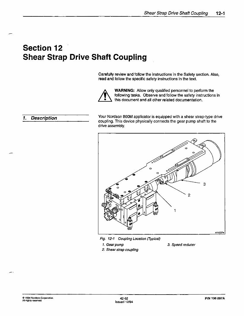
1. Description Your Nordson 800M applicator is equipped with a shear strap-type drive coupling. This device physically connects the gear pump shaft to the drive assembly.
4110374
Fig. 12-l Coupling Location (Typical)
1. Gear pump 3. Speed reducer
2. Shear strap coupling
0 1994 Nordson Corporation All rights reserved
42-62 Issued 12/94
PIN 106 897A

12-2 Shear Strap Drive Shaft Coupling
1. Description (contd.) In case of excessive drive torque (from an overpressure condition or blockage in the hydraulic system), the replaceable shear strap breaks, thereby separating the gear pump shaft from the drive assembly and
_ preventing damage to the gear pump.
The coupling disassembles easily into two halves for easy separation of the pump shaft from the reducer shaft. This is required when servicing the pump or drive assembly.
PM 106 897A 42-62 Issued V/94
0 1994 Not&on CorpOratiOn All rights reserved

Shear Strap Drive Shaft Coupling 12-3
2. Troubleshooting the - Drive Coupling
Problem Possible Cause Corrective Action Refer to
Broken drive Plugged dispensing nozzle(s) Clean or replace nozzle(s) Section 5, coupling shear subsection strap due to Nozzle excessive torque Cleaning in drive system
NOTE: The shear Adhesive not sufficiently melted Increase temperature setpoints to
strap is designed to when the pump is started normal settings. Avoid starting
break when the pump with below-normal
drive reaches a temperature settings
torque above its normal range
Adhesive with too high a viscosity Flush system and use lower Melter unit rating is being used viscosity adhesive manual; also
Section 5 of this manual, subsections filter Flushing and Filter Cleaning
Faulty dispensing device solenoid. 1. Check air supply to solenoid; Section 3, module remains closed while pump adjust if necessary subsection is on 2. Replace faulty solenoid Dispensing
Device and Recirculation Valve Solenoid Installation
Faulty dispensing module Repair or replace faulty module Section 9
Recirculation valve closed while the 1. Check air supply to solenoid; Section 3, dispensing module is also closed adjust if necessary subsection
2. Replace faulty solenoid Dispensing
3. Repair or replace faulty module Device and Recirculation Valve Solenoid Installation
Section 9
Solenoid wiring logic is incorrect Check wiring to ensure that solenoids receive the signal to trigger the modules when pump is operating
Section 3, subsection Dispensing Device and Recirculation Valve Solenoid Installation
Continued on next page
0 1994 No&on Corporation All rights reserved
42-62 Issued 12/94
PN 106 897A
12-4 Shear Strap Drive Shaft Coupling
Problem Possible Cause Corrective Action Refer to
Broken drive Pump binds or locks up Replace the pump Section 7, coupling shear subsection strap due to Rep/acing the excessive torque Gear Pump in drive system
Shear strap is misaligned Align the shear strap as described Replacing the later in this section Shear Strap
procedure in this section
3. Servicing the Drive Coupling
Removal 1. Shut down the applicator motor.
2. Lock out and disconnect input power from the applicator.
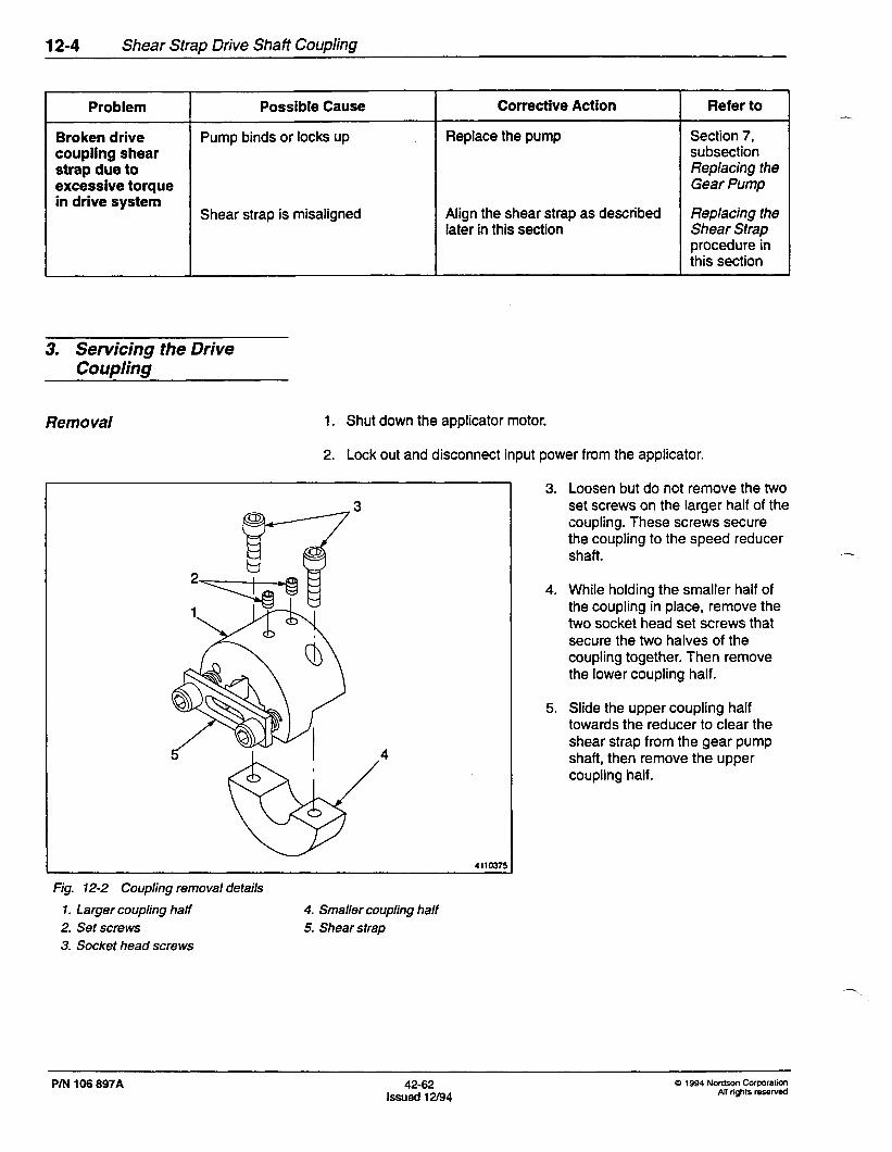
Fig. 72-2 Coupling removal details
1. Larger coupling half
2. Set screws
3. Socket head screws
4. Smaller coupling half
5. Shear strap
3. Loosen but do not remove the two set screws on the larger half of the coupling. These screws secure the coupling to the speed reducer shaft.
4. While holding the smaller half of the coupling in place, remove the two socket head set screws that secure the two halves of the coupling together. Then remove the lower coupling half.
5. Slide the upper coupling half towards the reducer to clear the shear strap from the gear pump shaft, then remove the upper coupling half.
PN 106 897A 42-62 lssued12/94
0 1994 Nordson Corporation All rights resewed
Shear Strap Drive Shaft Coupling 12-5
Checking and Aligning the - Pump Shaft and Speed Reducer
Shaft
Vertical Shaft Alignment
1. If the coupling is installed, remove it.
1’ ‘3 4110376
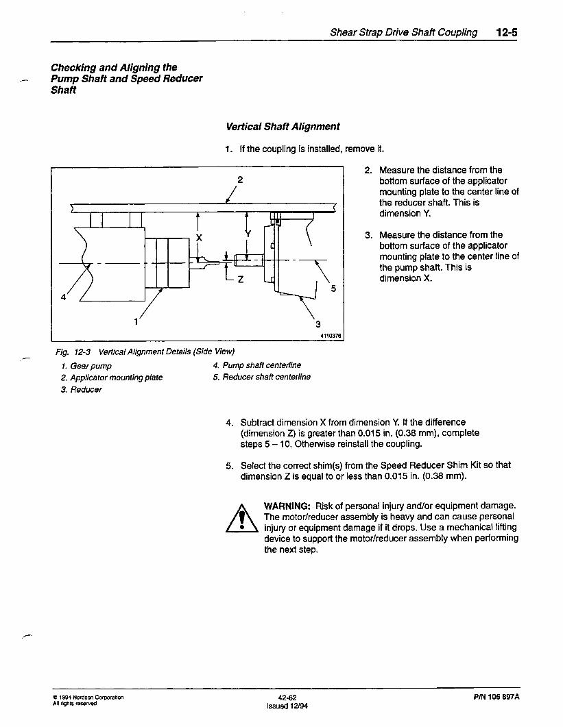
Fig. 12-3 Vertical Alignment Details (Side View)
1. Gear pump 4. Pump shaft centerline
2. Applica tar mounting plate 5. Reducer shaft centerline
3. Reducer
2. Measure the distance from the bottom surface of the applicator mounting plate to the center line of the reducer shaft. This is dimension Y.
3. Measure the distance from the bottom surface of the applicator mounting plate to the center line of the pump shaft. This is dimension X.
4. Subtract dimension X from dimension Y. If the difference (dimension 2) is greater than 0.015 in. (0.38 mm), complete steps 5 - 10. Otherwise reinstall the coupling.
5. Select the correct shim(s) from the Speed Reducer Shim Kit so that dimension Z is equal to or less than 0.015 in. (0.38 mm).
WARNING: Risk of personal injury and/or equipment damage. The motor/reducer assembly is heavy and can cause personal injury or equipment damage if it drops. Use a mechanical lifting device to support the motor/reducer assembly when performing the next step.
Q 1994 Nordson Corporation All rights reserved
42-62 Issued 12/94
PIN 106 897A

12-6 Shear Strap Drive Shaft Coupling
Vertical Shaft Alignment (contd.)
4
Fig. 12-4 Reducer Shim Details (Side View)
1. Shim(s) 3. Mounting bolts
2. Applica tar mounting plate 4. Reducer
6.
7.
8.
With a mechanical lifting device in place to support the motor/reducer assembly, remove the bolts that secure the reducer to the mounting plate.
Lower the motor/reducer assembly and insert the shim(s).
Raise the motor/reducer assembly into place, then reinstall and hand-tighten the mounting bolts.
--
P/N 106 697A 42-62 Issued 12/94
Q 1994 Nordson Corporation All rights reserved
Shear Strap Drive Shaft Coupling 12-7
..‘-.
Angular Shaft Alignment
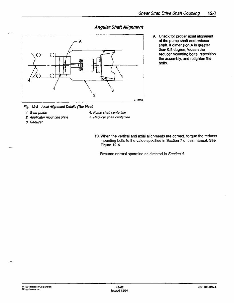
9. Check for proper axial alignment of the pump shaft and reducer shaft. If dimension A is greater than 0.5 degree, loosen the reducer mounting bolts, reposition the assembly, and retighten the bolts.
2 4110376
Fig. 12-5 Axial Alignment Details (Top Wew)
1. Gear pump 4. Pump shaft centerline
2, Applicator mounting plate 5. Reducer shaft centerline
3. Reducer
10. When the vertical and axial alignments are correct, torque the reducer mounting bolts to the value specified in Section 7 of this manual. See Figure 12-4.
Resume normal operation as directed in Section 4.
0 1994 No&on Corporation All rights reserved
42-62 Issued 12/94
P/N 106 897A

12-8 Shear Strap Drive Shaft Coupring
Installation
‘T c C
1
4
1. Place the larger coupling half on the reducer shaft so the coupling keyway aligns with the reducer shaft key.
Fig. 12-6 Coupling Installation Details
1. Reducer shaft end 3. Reducer
2. Larger coupling half 4. Smaller coupling half
-.
2. Adjust the coupling half so that the shear strap engages with the pump shaft tang.
NOTE: If it is necessary to align the shear strap slot with the pump shaft tang:
- On DC drives, remove the fan cover from the end of the motor, hand-turn the fan blades until the shear strap slot aligns with the pump shaft tang, then reinstall the motor fan cover.
- On AC drives, electrically jog the motor until the shear strap slot aligns with the pump shaft tang.
3. Install the smaller coupling half and two socket head screws. Do not tighten the screws yet. See Figure 12-2.
P/N 106 897A 42-62 issued 12/94
0 1994 Nordson COrpOration
All rights reserved
Shear Strap Drive Shaft Coupling 12-9
A---
#--
/?ISta//atiOn (contd.)
2 411ow
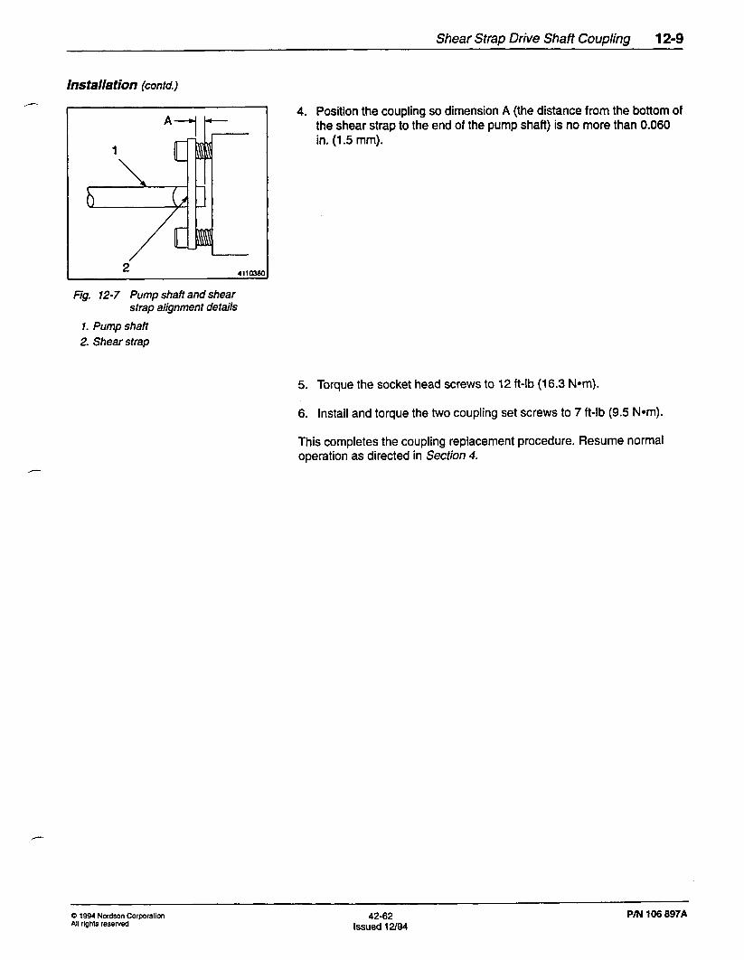
Fig. 12-7 Pump shaft and shear strap alignment details
1. Pump shaft
2. Shear strap
4. Position the coupling so dimension A (the distance from the bottom of the shear strap to the end of the pump shaft) is no more than 0.060 in. (1.5 mm).
5. Torque the socket head screws to 12 ft-lb (16.3 Nom).
6. Install and torque the two coupling set screws to 7 ft-lb (9.5 Nom).
This completes the coupling replacement procedure. Resume normal operation as directed in Section 4.
Q 1994 Nordson Corporation All rights reserved
42-62 Issued 12/94
P/N 106 897A

1240 Shear Strap Drive Shaft Coupling
Replacing the Shear Strap The drive coupling shear strap is designed to break if the torque rating of the strap is exceeded.
Do not replace the shear strap until the cause of the excessive torque is found and corrected.
1. Remove the coupling as described eartier in this section.
1 1
Fig. 12-8 Shear Strap Installed Fig. 12-8 Shear Strap Installed
1. Socket head shoulder screws 1. Socket head shoulder screws
2. 2. Shear strap Shear strap
3. 3. Spring Spring
4. Smaller coupling half 4. Smaller coupling half
5. 5. Larger Larger coupling coupling half half
2. Remove the two socket shoulder head screws, shear strap pieces, and springs. Discard the old shear strap pieces.
3. Obtain a new shear strap with the same breaking torque as the old one (150, 300,450, or 600 in.-lb). See table of replacement shear strap part numbers at end of this section.
4. Insert the two socket head shoulder screws through the new shear strap mounting holes.
P/N 106 697A 42-62 Q 1994 No&cm Corporation
issued 12/94 All rights reserved

Shear Strap Drive Shaft Coupling 12-I 1
Rep/acing the Shear Strap /- (contd.)
4110382
Fig. 12-9 Shear Strap Mounting Details
1. Socket head shoulder screws
2. Shear strap
3. Spring
4. Coupling
- 7. Reinstall the coupling assembly.
5. Install a spring onto each screw, then start threading the two screws into the coupling. Alternately tighten one screw and then the other until the screw shoulders touch the coupling.
6. Tighten the shoulder screws.
This completes the procedure for replacing the coupling shear strap. Resume normal operation as directed in Section 4.
Q 1994 Nordson Corporation All rights reserved
42-62 Issued 12l94
PM 106 697A

12-12 Shear Strap Drive Shaft Coupling
4. Parts List with Illustration
Shear Strap Drive Coupling (Typical)
Item Item Part Part Description Description Quantity Quantity Note Note
1 1 164219 Coupling, Shear Strap, 0.875 in. 164219 Coupling, Shear Strap, 0.875 in. 1 1 (22.2 mm) bore (22.2 mm) bore
2 2 981233 Screw, Socket Head 981233 Screw, Socket Head 2 2
3 3 981576 Screw, Socket Set, IO-24 x 0.25 981576 Screw, Socket Set, IO-24 x 0.25 in. in. 2 2
4 4 Spring, Compression Spring, Compression 2 2 A A
5 5 Strap, Shear Strap, Shear 1 1 A A
6 6 Screw, Shoulder, Socket Head Screw, Shoulder, Socket Head 2 2 A A I I NOTE A: These items differ, depending on which drive coupling assembly is used. NOTE A: These items differ, depending on which drive coupling assembly is used.
L L
Fig. Fig. 12- 12- 10 10 Drive Drive Coupling Assembly Coupling Assembly
-
PIN 106 897A 42-62 0 1994 Nordson Corporation
Issued 12/94 All rights resewed
Shear Strap Drive Shaft Coupling 12-l 3
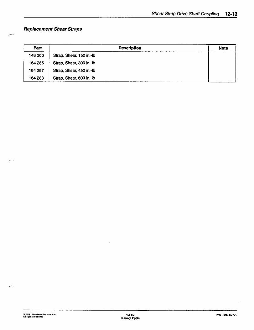
Replacement Shear Straps
Part Description Note
146 300 Strap, Shear, 150 in.-lb
164286 Strap, Shear, 300 in.-lb
164 287 Strap, Shear, 450 in.-lb
164 288 Strap, Shear, 600 in.-lb
0 1994 Nor&on Corporation All rights reserved
42-62 lssued12/94
PIN 106 897A

12-14 Shear Strap Drive Shaft Coupling
P/N 106 897A 42-62 0 1994 No&on Corporatim
Issued 12/94 All rights reserved