Embed Size (px)
Citation preview
University of Thi-Qar Journal
ISSN (print): 2706- 6908, ISSN (online): 2706-6894
Vol.15 No.2 June 2020
20
Shear Strength Evaluation of Directly and Indirectly Loaded
Rectangular Recycled Self-Compacted Reinforced Concrete
Slender Beams Using Experimental and Finite Element
Analysis
Thamer Hussein Amer Alhussein a, Asst. Prof. Dr. Jamal Abdul Samad
Khudhairb
a Department of Civil Engineering, College of Engineering, University of
Basrah, the Ph.D. candidate the University of Basrah, [email protected] b Department of Civil Engineering, College of Engineering, University of
Basrah, Asst. Professor University of Basrah,
https://doi.org/10.32792/utq/utj/vol15/2/3
Abstract
This study presents an experimental and numerical evaluation of the shear
behavior of recycled aggregate concrete beams without transversal
reinforcement. These beams were manufactured as self-compacted concrete
with the use of both natural aggregate and recycled aggregate. The beams
were subjected to direct and indirect loading conditions. The mechanical
properties of four mixes were characterized in terms of compressive
strength, splitting tensile strength, and elastic modulus. The experimental
results showed that the shear capacity of recycled aggregate concrete is
lower than those made with natural aggregate. The experimental shear
capacities of the tested beams were compared with ACI318M-14 and
relevant research studies in the literature. The ratio of experimental shear
stress divided by the root square of concrete compressive strength (𝑣𝑒𝑥𝑝/
√𝑓𝑐`), which indicates the ability of diagonally cracked concrete to transmit
tension and shear. was remained for all configurations greater than 0.17,
which is the minimum value recommended by the ACI318-14. Results from
University of Thi-Qar Journal
ISSN (print): 2706- 6908, ISSN (online): 2706-6894
Vol.15 No.2 June 2020
21
nonlinear finite element models were compared with the experimental data,
and good agreement was achieved.
Keywords: Rectangular Beam, Mechanical Properties, Finite Element
Method (FEM), Shear Strength, Indirect Load, and Recycled Aggregate Self-
Compacted Concrete (RASCC)
1. Introduction
Despite extensive research to understand the mechanism that governs the
shear failure of slender concrete beams, and after almost 70 years of
research, it is still unsolved. although those studies have proposed a large
number of models, most of those models were developed by fitting existing
experimental data. Thus, they are either empirical or Semi-empirical. The
lack of a clear adequate theory for shear is more evident in codes of practice
worldwide. For example, the American Concrete Institute Code (ACI 318-
14), employs more than forty empirical equations to assess the shear strength
of concrete structures in general [1]. Each of which is fitted for a specific
concrete member or a certain condition. The present work aims to
characterize the effect of recycled aggregates on the shear capacity of
reinforced concrete beams. The shear failure is one of the most critical
failure modes for reinforced concrete structures especially for members
without transversal reinforcement. The maximum shear strength depends on
many parameters such as the concrete compressive strength (𝑓𝑐`), the
longitudinal reinforcement ratio (𝜌𝑙), the shear span to depth ratio (𝑎/𝑑), the
aggregates size (𝑑𝑔), and the transversal reinforcement ratio. The shear
span-to-depth ratio is mainly depending. Research programs have been
conducted in the literature on the shear capacity and the shear failure
mechanisms of beams made with concrete incorporating mainly recycled
coarse aggregates. Alhussein and Khudhair (2020)[2] studied, reinforced
University of Thi-Qar Journal
ISSN (print): 2706- 6908, ISSN (online): 2706-6894
Vol.15 No.2 June 2020
22
concrete rectangular deep beams cast with self-compacted concrete (SCC)
which contains recycled concrete as coarse aggregate (RCA) were tested
under directly and indirectly loading conditions. In the experimental work,
fifteen deep beams were investigated, the first parameter considered in this
study was the shear span to effective depth (a/d) ratio. The other variable is
the replacement ratio by which the normal coarse aggregate is replaced by
RCA. The beams were cast without the use of shear reinforcement. During
the tests, the response of the beams including the cracking load, the ultimate
load, concrete strain, and mid-span deflection were recorded. Test results
indicate that the presence of RCA caused a reduction in the values of
cracking and ultimate loads. For instance, the cracking load was reduced by
9%, 23%, and 50% and the ultimate load was reduced by 2%, 23%, and 25%
as RCA replacement increased by 25%, 50%, and 75% respectively for a/d
ratio equals 1.0. Further, by increasing the a/d ratio, the ultimate load was
decreased due to the lower contribution of arch action shear transfer in the
beam with a higher (a/d) ratio. Gonzalez et al. (2007) [3] tested eight beams
made from two concrete compositions with a 3% longitudinal reinforcement
ratio. The first mixture was based on natural aggregates, while the second
was formulated with 50% recycled coarse aggregates. The beams were tested
in four-point bending up to shear failure with 𝑎/𝑑 = 3.3. Their study's
results showed no significant difference between recycled aggregate concrete
(RCA), and natural aggregate concrete (NAC) beams. They observed notable
splitting cracks and tension reinforcement, especially for RAC beams
without transversal reinforcement. Gonzalez et al. (2009) [4] repeated the
previous study by adding 8% silica fume to the mix designs. They observed
that the addition of silica fume mitigated the splitting cracks along with the
University of Thi-Qar Journal
ISSN (print): 2706- 6908, ISSN (online): 2706-6894
Vol.15 No.2 June 2020
23
tension reinforcements. Etxeberria et al. (2007) [5] tested twelve beams
made from four concrete formulations of the same class of compressive
strength with different coarse recycled aggregate replacement ratios (0%,
25%, 50%, and 100%). Also, beams prepared with a longitudinal
reinforcement ratio ranged from 2.92% to 2.95% and tested with 𝑎/𝑑 =
3.0. The results showed that the effect of recycled aggregates on the shear
strength depends on the substitution ratio and especially for beams without
shear reinforcement.
Chkheiwer A. H. (2013) [6] studied the influence of mixed proportions on
the properties of fresh and hardened SCC. The effect of coarse aggregate
content, limestone powder (LSP) to total powder ratio, and water/powder
ratio on the SCC's fresh and hardened properties were considered. Different
test methods were adopted to determine the properties of fresh SCC, such as
slump flow, T500, V-funnel, L-box, and sieve segregation tests. The results
showed that it is possible to produce SCC from locally available materials,
which satisfy this type of concrete. Moreover, it can be clarified that the
produced SCC is sensitive to the amount of coarse aggregate, amount of
fillers, superplasticizer dosage, and water/powder ratio. The second part of
the Chkheiwer study investigated the influence of the type of concrete (SCC
and NC) and three values of compressive strength on the flexural and shear
behavior of reinforced concrete beams and the punching shear of slabs. SCC
slender beams failing in shear showed higher ultimate loads than the NC
beam for different concrete compressive strength. While for deep beams
failing in shear, both types of beams showed almost the same ultimate loads.
University of Thi-Qar Journal
ISSN (print): 2706- 6908, ISSN (online): 2706-6894
Vol.15 No.2 June 2020
24
2. Significance of Work-Study
Although slender beams are widely used in construction projects, the
evaluation of ultimate strength still has many uncertainties about
understanding the behavior and the failure mechanism of these elements.
There are a limited number of research studies in the literature that have
been conducted to investigate the response of beams made with self
compacted RA concrete. Thus, this research tries to fill the gap and
presented a thorough study that includes an experimental, code-based, and
FE evaluation to investigate the responses of such elements. Furthermore,
studying the effect of indirect loading conditions on the response of RASCC
beams are less documented even in international standards like ACI.
Therefore, this research presents a detailed study and offers an
experimentally-quantified approach that can be utilized to implement
indirect loading conditions on the response of beams. Another importance of
this research which is characterized by the combination of using slender
beams prepared using RCA as a partial replacement of NA and utilizing the
SCC technique. This combination produces more sustainable structural
elements and eliminates construction efforts.
3. Materials Properties
The experimental work carried out in the laboratory of the civil engineering
department, University of Basrah. The mechanical properties of all types of
concrete used in this work, control specimens were casting from the same
mixes used for the SCC beams. Three mechanical properties were evaluated
here: compressive strength (𝑓𝑐`), splitting tensile strength (𝑓𝑡), and modulus
of elasticity (𝐸𝑐). Three cubes and two cylinders were used for each mixture.
The mechanical properties of concrete mixes are presented in Table1.
University of Thi-Qar Journal
ISSN (print): 2706- 6908, ISSN (online): 2706-6894
Vol.15 No.2 June 2020
25
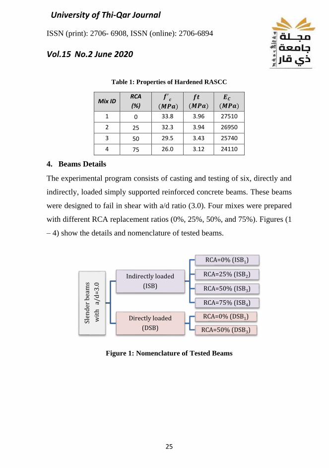
Table 1: Properties of Hardened RASCC
Mix ID RCA
(%)
𝒇′𝒄
(𝑴𝑷𝒂)
𝒇𝒕
(𝑴𝑷𝒂)
𝑬𝑪
(𝑴𝑷𝒂)
1 0 33.8 3.96 27510
2 25 32.3 3.94 26950
3 50 29.5 3.43 25740
4 75 26.0 3.12 24110
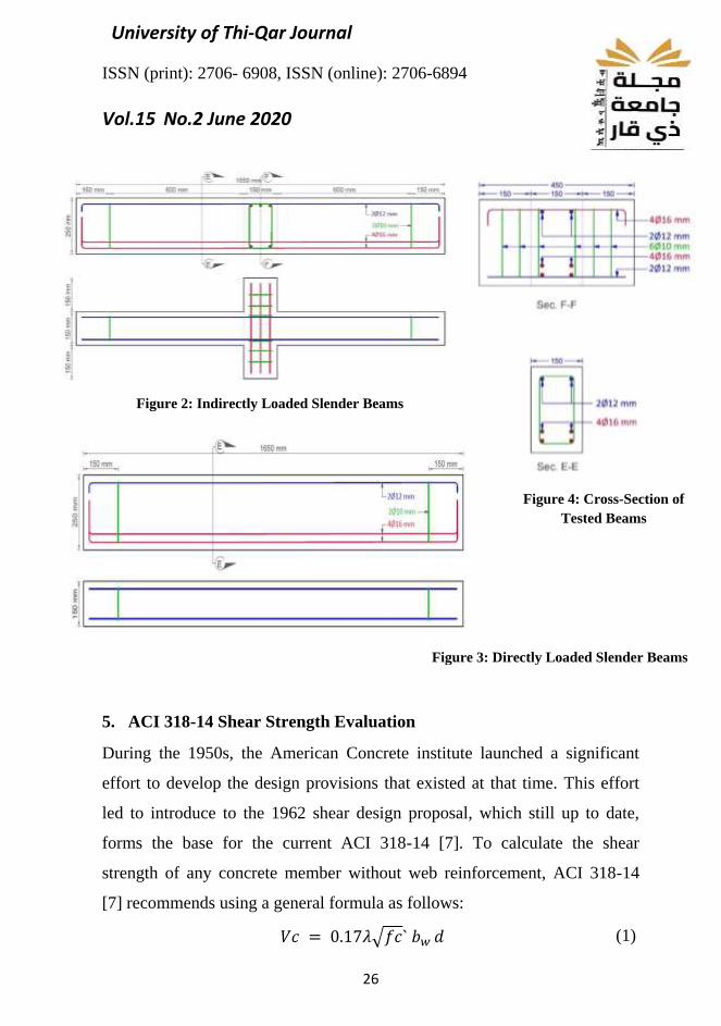
4. Beams Details
The experimental program consists of casting and testing of six, directly and
indirectly, loaded simply supported reinforced concrete beams. These beams
were designed to fail in shear with a/d ratio (3.0). Four mixes were prepared
with different RCA replacement ratios (0%, 25%, 50%, and 75%). Figures (1
– 4) show the details and nomenclature of tested beams.
Figure 1: Nomenclature of Tested Beams
Slen
der
bea
ms
wit
h
a/d
=3
.0
Indirectly loaded
(ISB)
RCA=0% (ISB1)
RCA=25% (ISB2)
RCA=50% (ISB3)
RCA=75% (ISB4)
Directly loaded
(DSB)
RCA=0% (DSB1)
RCA=50% (DSB3)
University of Thi-Qar Journal
ISSN (print): 2706- 6908, ISSN (online): 2706-6894
Vol.15 No.2 June 2020
26
5. ACI 318-14 Shear Strength Evaluation
During the 1950s, the American Concrete institute launched a significant
effort to develop the design provisions that existed at that time. This effort
led to introduce to the 1962 shear design proposal, which still up to date,
forms the base for the current ACI 318-14 [7]. To calculate the shear
strength of any concrete member without web reinforcement, ACI 318-14
[7] recommends using a general formula as follows:
𝑉𝑐 = 0.17𝜆√𝑓𝑐` 𝑏𝑤 𝑑 (1)
Figure 3: Directly Loaded Slender Beams
Figure 2: Indirectly Loaded Slender Beams
Figure 4: Cross-Section of
Tested Beams
University of Thi-Qar Journal
ISSN (print): 2706- 6908, ISSN (online): 2706-6894
Vol.15 No.2 June 2020
27
Where 𝑏𝑤; d represents the width and depth of the section respectively, 𝜆 is a
factor to account for the density of concrete, while √𝑓𝑐` is the compressive
strength of concrete. As shown, 𝐸𝑞. (1) accounts for neither the size effect
nor the influence of longitudinal reinforcement. However, ACI 318-14 [7]
gives a more accurate method to calculate the shear strength. The method
consists of three different formulas in which the shear strength of the
member shall be the lesser of them.
𝑉𝑐 = (0.16 𝜆√𝑓𝑐` + 17𝜌𝑤
𝑉𝑢 𝑑
𝑀𝑢) 𝑏𝑤 𝑑 (2)
𝑉𝑐 = (0.16 𝜆√𝑓𝑐` + 17𝜌𝑤 )𝑏𝑤 𝑑 (3)
𝑉𝑐 = 0.17𝜆√𝑓𝑐` 𝑏𝑤 𝑑 (4)
Where 𝑉𝑢, 𝑀𝑢 represent the ultimate shear and moment at the section
considered respectively, 𝜌𝑤 is the ratio of longitudinal reinforcement. Also,
since 𝑀𝑢 = 𝑉𝑢𝑎, it is possible to replace the term (𝑉𝑢𝑑/𝑀𝑢) in Eq. (2) by the
term (𝑎/𝑑), where 𝑎 is the shear span of the member.
6. Experimental results
The results of hardened concrete tests are presented in Table 1. The test
results showed that the compressive strength, modulus of elasticity, and
splitting tensile strength were decreased by the increase of the RCA
replacement ratio. For instance, increasing the RCA replacement ratio to
25%, 50%, and 75%; the compressive strength decreased by (4%, 13%, and
23%). The splitting tensile strength decreased by (1%, 13 %, and 21%)
respectively. Also, it can be observed that the modulus of elasticity was
reduced with the increased RA ratio by (2%, 6%, and 12%) respectively .
This reduction is due to the composition of recycled aggregate, which
University of Thi-Qar Journal
ISSN (print): 2706- 6908, ISSN (online): 2706-6894
Vol.15 No.2 June 2020
28
generally consists of considerable amounts of porous old mortars that form
zones of weakness in the concrete composite.
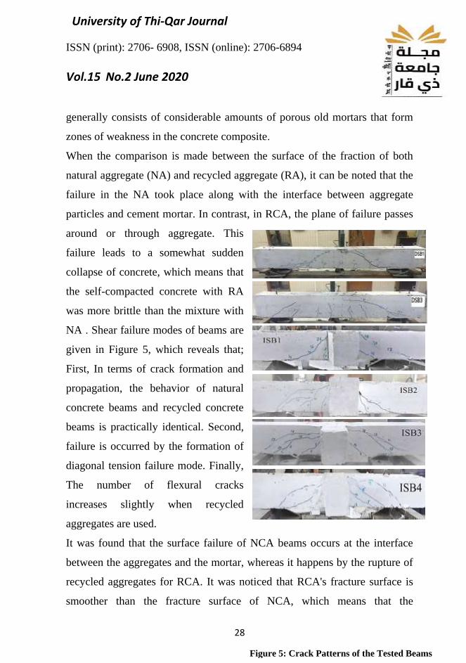
When the comparison is made between the surface of the fraction of both
natural aggregate (NA) and recycled aggregate (RA), it can be noted that the
failure in the NA took place along with the interface between aggregate
particles and cement mortar. In contrast, in RCA, the plane of failure passes
around or through aggregate. This
failure leads to a somewhat sudden
collapse of concrete, which means that
the self-compacted concrete with RA
was more brittle than the mixture with
NA . Shear failure modes of beams are
given in Figure 5, which reveals that;
First, In terms of crack formation and
propagation, the behavior of natural
concrete beams and recycled concrete
beams is practically identical. Second,
failure is occurred by the formation of
diagonal tension failure mode. Finally,
The number of flexural cracks
increases slightly when recycled
aggregates are used.
It was found that the surface failure of NCA beams occurs at the interface
between the aggregates and the mortar, whereas it happens by the rupture of
recycled aggregates for RCA. It was noticed that RCA's fracture surface is
smoother than the fracture surface of NCA, which means that the
Figure 5: Crack Patterns of the Tested Beams
University of Thi-Qar Journal
ISSN (print): 2706- 6908, ISSN (online): 2706-6894
Vol.15 No.2 June 2020
29
contribution of bridging and the branching phenomenon is reduced in the
stress transfer between the two lips of the crack. [8]. The microscopic
observations showed that the crack of RCA is broader than NCA beams.
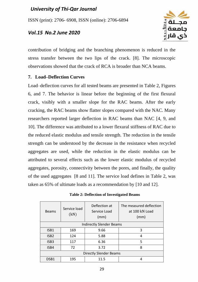
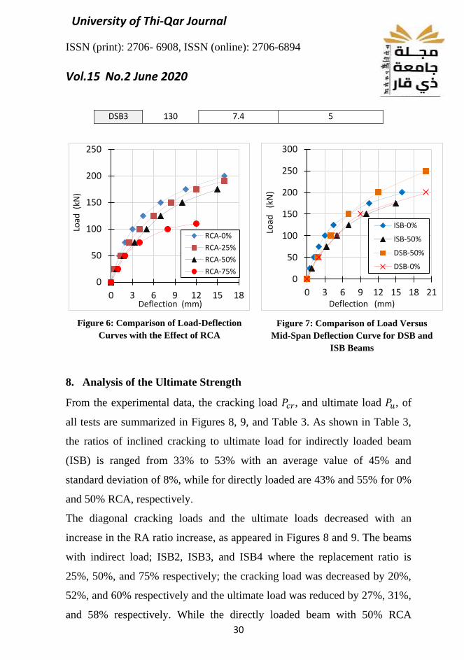
7. Load–Deflection Curves
Load–deflection curves for all tested beams are presented in Table 2, Figures
6, and 7. The behavior is linear before the beginning of the first flexural
crack, visibly with a smaller slope for the RAC beams. After the early
cracking, the RAC beams show flatter slopes compared with the NAC. Many
researchers reported larger deflection in RAC beams than NAC [4, 9, and
10]. The difference was attributed to a lower flexural stiffness of RAC due to
the reduced elastic modulus and tensile strength. The reduction in the tensile
strength can be understood by the decrease in the resistance when recycled
aggregates are used, while the reduction in the elastic modulus can be
attributed to several effects such as the lower elastic modulus of recycled
aggregates, porosity, connectivity between the pores, and finally, the quality
of the used aggregates [8 and 11]. The service load defines in Table 2, was
taken as 65% of ultimate loads as a recommendation by [10 and 12].
Table 2: Deflection of Investigated Beams
Beams Service load
(kN)
Deflection at
Service Load
(mm)
The measured deflection
at 100 kN Load
(mm)
Indirectly Slender Beams
ISB1 169 9.66 3
ISB2 124 5.88 4
ISB3 117 6.36 5
ISB4 72 3.72 8
Directly Slender Beams
DSB1 195 11.5 4
University of Thi-Qar Journal
ISSN (print): 2706- 6908, ISSN (online): 2706-6894
Vol.15 No.2 June 2020
30
0
50
100
150
200
250
0 3 6 9 12 15 18
Load
(kN
)
Deflection (mm)
RCA-0%
RCA-25%
RCA-50%
RCA-75%
DSB3 130 7.4 5
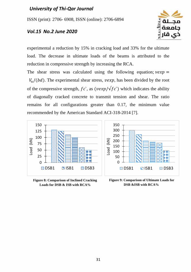
8. Analysis of the Ultimate Strength
From the experimental data, the cracking load 𝑃𝑐𝑟, and ultimate load 𝑃𝑢, of
all tests are summarized in Figures 8, 9, and Table 3. As shown in Table 3,
the ratios of inclined cracking to ultimate load for indirectly loaded beam
(ISB) is ranged from 33% to 53% with an average value of 45% and
standard deviation of 8%, while for directly loaded are 43% and 55% for 0%
and 50% RCA, respectively.
The diagonal cracking loads and the ultimate loads decreased with an
increase in the RA ratio increase, as appeared in Figures 8 and 9. The beams
with indirect load; ISB2, ISB3, and ISB4 where the replacement ratio is
25%, 50%, and 75% respectively; the cracking load was decreased by 20%,
52%, and 60% respectively and the ultimate load was reduced by 27%, 31%,
and 58% respectively. While the directly loaded beam with 50% RCA
Figure 6: Comparison of Load-Deflection
Curves with the Effect of RCA
0
50
100
150
200
250
300
0 3 6 9 12 15 18 21
Load
(k
N)
Deflection (mm)
ISB-0%
ISB-50%
DSB-50%
DSB-0%
Figure 7: Comparison of Load Versus
Mid-Span Deflection Curve for DSB and
ISB Beams
University of Thi-Qar Journal
ISSN (print): 2706- 6908, ISSN (online): 2706-6894
Vol.15 No.2 June 2020
31
experimental a reduction by 15% in cracking load and 33% for the ultimate
load. The decrease in ultimate loads of the beams is attributed to the
reduction in compressive strength by increasing the RCA.
The shear stress was calculated using the following equation; 𝜈𝑒𝑥𝑝 =
𝑉𝑢/(𝑏𝑑). The experimental shear stress, 𝑣𝑒𝑥𝑝, has been divided by the root
of the compressive strength, 𝑓𝑐`, as (𝑣𝑒𝑥𝑝/√𝑓𝑐`) which indicates the ability
of diagonally cracked concrete to transmit tension and shear. The ratio
remains for all configurations greater than 0.17, the minimum value
recommended by the American Standard ACI-318-2014 [7].
0
25
50
75
100
125
150
Load
(kN
)
DSB1 ISB1 DSB3
0
50
100
150
200
250
300
350
Load
(kN
)
DSB1 ISB1 DSB3
Figure 8: Comparison of Inclined Cracking
Loads for DSB & ISB with RCA% Figure 9: Comparison of Ultimate Loads for
DSB &ISB with RCA%
University of Thi-Qar Journal
ISSN (print): 2706- 6908, ISSN (online): 2706-6894
Vol.15 No.2 June 2020
32
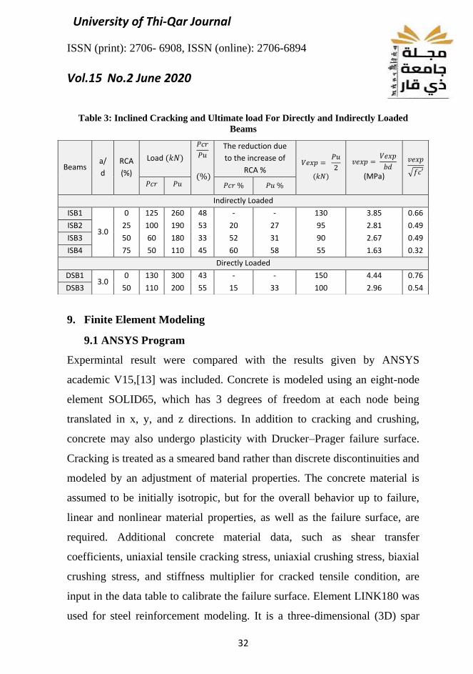
Table 3: Inclined Cracking and Ultimate load For Directly and Indirectly Loaded
Beams
9. Finite Element Modeling
9.1 ANSYS Program
Expermintal result were compared with the results given by ANSYS
academic V15,[13] was included. Concrete is modeled using an eight-node
element SOLID65, which has 3 degrees of freedom at each node being
translated in x, y, and z directions. In addition to cracking and crushing,
concrete may also undergo plasticity with Drucker–Prager failure surface.
Cracking is treated as a smeared band rather than discrete discontinuities and
modeled by an adjustment of material properties. The concrete material is
assumed to be initially isotropic, but for the overall behavior up to failure,
linear and nonlinear material properties, as well as the failure surface, are
required. Additional concrete material data, such as shear transfer
coefficients, uniaxial tensile cracking stress, uniaxial crushing stress, biaxial
crushing stress, and stiffness multiplier for cracked tensile condition, are
input in the data table to calibrate the failure surface. Element LINK180 was
used for steel reinforcement modeling. It is a three-dimensional (3D) spar
Beams a/
d
RCA
(%)
Load (𝑘𝑁)
𝑃𝑐𝑟
𝑃𝑢
(%)
The reduction due
to the increase of
RCA % 𝑉𝑒𝑥𝑝 =
𝑃𝑢
2
(𝑘𝑁)
𝑣𝑒𝑥𝑝 = 𝑉𝑒𝑥𝑝
𝑏𝑑
(MPa)
𝑣𝑒𝑥𝑝
√𝑓𝑐′
𝑃𝑐𝑟 𝑃𝑢 𝑃𝑐𝑟 % 𝑃𝑢 %
Indirectly Loaded
ISB1
3.0
0 125 260 48 - - 130 3.85 0.66
ISB2 25 100 190 53 20 27 95 2.81 0.49
ISB3 50 60 180 33 52 31 90 2.67 0.49
ISB4 75 50 110 45 60 58 55 1.63 0.32
Directly Loaded
DSB1 3.0
0 130 300 43 - - 150 4.44 0.76
DSB3 50 110 200 55 15 33 100 2.96 0.54
University of Thi-Qar Journal
ISSN (print): 2706- 6908, ISSN (online): 2706-6894
Vol.15 No.2 June 2020
33
element with 3 degrees of freedom at each node being translated in x, y, and
z directions. The element cannot carry bending loads, while creep, plasticity,
rotation, large deflection, and large strain capabilities are included. For rebar
reinforcement, an elastic, perfect plastic material model was adopted.
Poisson’s ratio was set to 0.3, whereas elastic modulus and yield stress were
set equal to experimental values. The full bond used to model the bond
between steel rebar and concrete [8]. For the supports and the loading plates,
the SOLID185 element was used. It is defined by eight nodes having 3
degrees of freedom at each node being translated in the nodal x, y, and z. It
is capable of plasticity, hyper elasticity, stress stiffening, creep, large
deflection, and large strain
capabilities. Full and one half of the
beam was modeled, taking into
account the symmetry of both
geometry and loading. The total load
was applied through a series of load
steps, and the analysis type was set to
small displacement static, where large
deformation effects are ignored. The
sparse direct solver based on the
immediate elimination of equations was used to solve the model. The
iterative process of the Newton–Raphson method was used to solve the
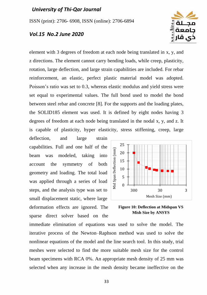
nonlinear equations of the model and the line search tool. In this study, trial
meshes were selected to find the more suitable mesh size for the control
beam specimens with RCA 0%. An appropriate mesh density of 25 mm was
selected when any increase in the mesh density became ineffective on the
0
5
10
15
20
25
330300
Mid
Sp
an D
efle
ctio
n (
mm
)
Mesh Size (mm)
Figure 10: Deflection at Midspan VS
Mish Size by ANSYS
University of Thi-Qar Journal
ISSN (print): 2706- 6908, ISSN (online): 2706-6894
Vol.15 No.2 June 2020
34
accuracy of the results. Figure 10 shows the mid-span deflection with the
trial meshing of FE by ANSYS.
9.2 ABAQUS Program
Detailed 3D finite element models of RC beams were implemented in this
study. The FE models were created using FE commercial software package
ABAQUS [14] to predict ultimate shear capacity and comparing the results
with experimental data. FE models were
refined and calibrated using experimental
data to extend them to predict other
parameters that were not measured during
the experimental program. The models
were subjected to direct and indirect
loading to evaluate their shear capacity.
The geometry of the FE models was taken
from experimental tests. All lab-measured
dimensions, reinforcement details were used
in FE models as shown in Figures 2,3, and 4. The mechanical properties of
concrete adopted in FE models were taken according to the experimental
program. Table 1 presents the properties of the concrete used in this study
with Poisson's ratio of 0.2 for concrete under uniaxial compression. Concrete
Damage Plasticity model (CDM) was used to model concrete behavior.
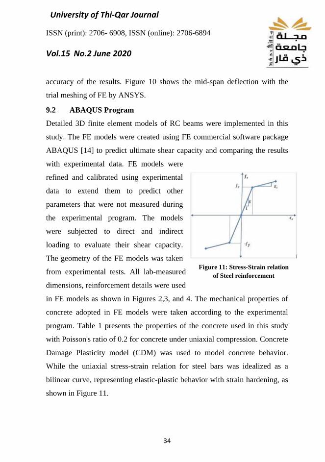
While the uniaxial stress-strain relation for steel bars was idealized as a
bilinear curve, representing elastic-plastic behavior with strain hardening, as
shown in Figure 11.
Figure 11: Stress-Strain relation
of Steel reinforcement
University of Thi-Qar Journal
ISSN (print): 2706- 6908, ISSN (online): 2706-6894
Vol.15 No.2 June 2020
35
In the numerical simulation, a three-dimensional eight-node linear brick and
reduced integration with hourglass control solid element (C3D8R) are
employed to represent the concrete specimen. While a three-dimensional,
truss elements with 2-node first order (T3D2– Truss) are used to model the
steel reinforcements. Many research studies in the literature have
recommended using these elements to model the tested beams [10, and 15].
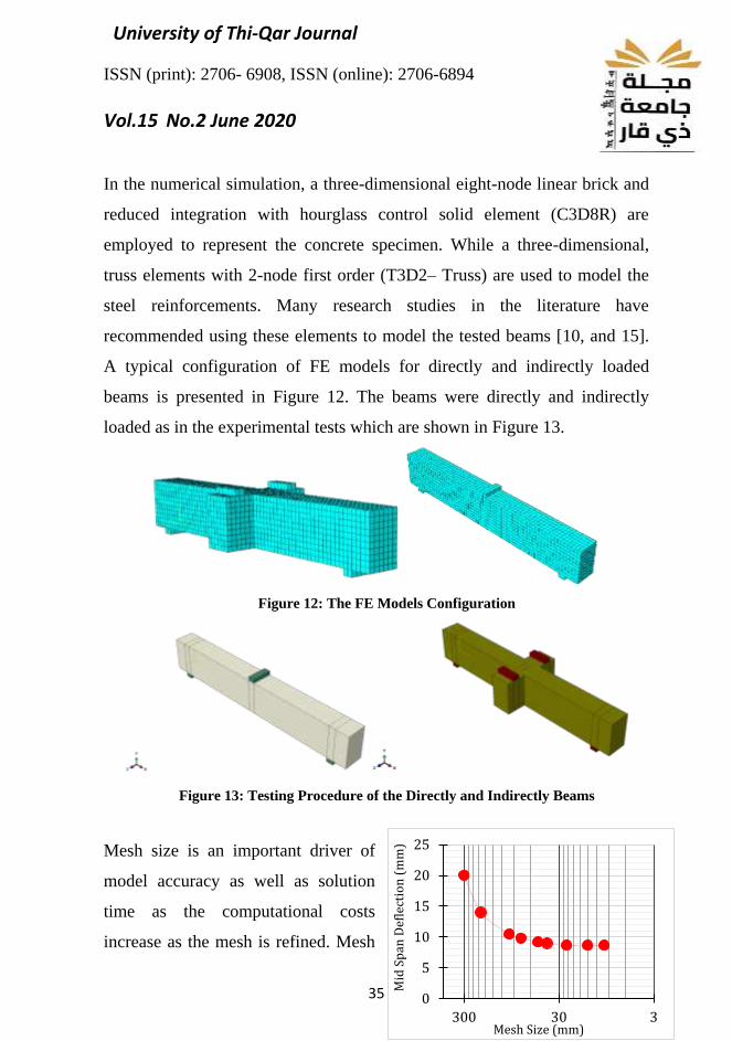
A typical configuration of FE models for directly and indirectly loaded
beams is presented in Figure 12. The beams were directly and indirectly
loaded as in the experimental tests which are shown in Figure 13.
Figure 12: The FE Models Configuration
Figure 13: Testing Procedure of the Directly and Indirectly Beams
Mesh size is an important driver of
model accuracy as well as solution
time as the computational costs
increase as the mesh is refined. Mesh
0
5
10
15
20
25
330300
Mid
Sp
an D
efle
ctio
n (
mm
)
Mesh Size (mm)
University of Thi-Qar Journal
ISSN (print): 2706- 6908, ISSN (online): 2706-6894
Vol.15 No.2 June 2020
36
size was the key parameter for calibration of the FE models to determine the
mesh density that gives convergent results with reasonable computation
time. Mesh refinement was addressed by running the model with a different
mesh size and studying its effect on the midspan deflection. Mesh size
versus midspan deflection is presented in Figure 14. The optimum mesh size
of 25mm gives good FE results with reasonable computational time.
10. Comparison with Experimental Results
Validation of the proposed model, a comparison with experimental results
and finite element model was performed. Load versus mid-span deflection
curves from numerical analysis and experiments for RASCC beams are
shown in Figures 15 and 16. The comparison of curves indicates that both
experimental and numerical results are in good agreement .

University of Thi-Qar Journal
ISSN (print): 2706- 6908, ISSN (online): 2706-6894
Vol.15 No.2 June 2020
37
The curves of FE load-deflection differ slightly from the experimental
curves; this because of the, existince of the micro-cracks in the real concrete
specimens formed through drying shrinkage in the concrete and beam
handling. On the other hand, the FE models do not deal with micro cracks.
Second, the bonding of concrete and steel as perfect in the FE model.
However, this assumption is not valid for the experimental tests.
Furthermore, the appearance of the cracks reflects the failure modes for the
specimens.
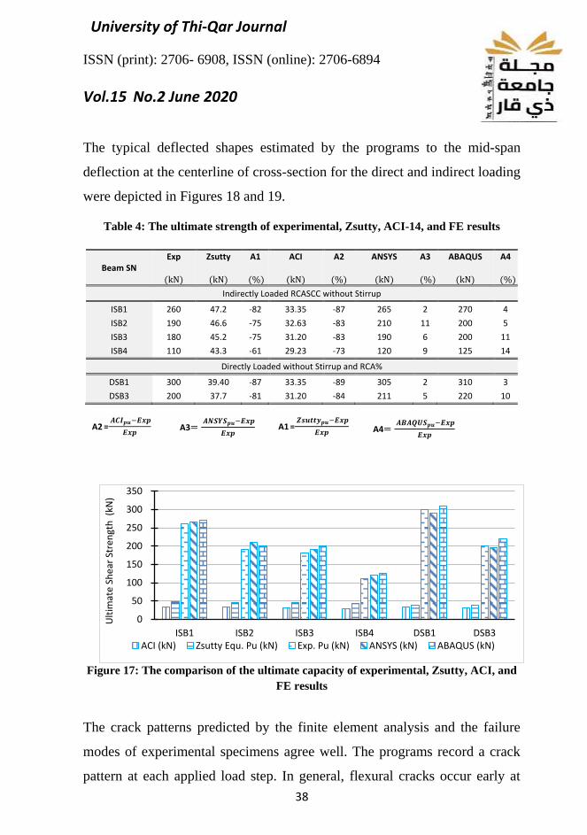
The comparison between the experimental shear strength and the predicted
resistances for all tested beams are presented in Table 4 and Figure 17. It can
be seen that the predictions yielded by zsutty equations and ACI ordinary
method are more conservative than FE models. Likewise, FE results were
closed with experimental findings .
Figure 15: Load Midspan Deflection
Curves for Indirectly Loaded Beams
0
25
50
75
100
125
150
175
200
225
0 2 4 6 8 10 12 14 16 18 20 22
Load
(kN
)
Deflection (mm)
RCA 50%
Experimental
FE-Ansys
FE-Abaqus
0
25
50
75
100
125
150
175
200
0 2 4 6 8 10 12 14 16Lo
ad (
kN)
Deflection (mm)
R C A 5 0 %
Experimental
FE-Ansys
FE-Abaqus
Figure 16: Load Midspan Deflection
Curves for Directly Loaded Beams
University of Thi-Qar Journal
ISSN (print): 2706- 6908, ISSN (online): 2706-6894
Vol.15 No.2 June 2020
38
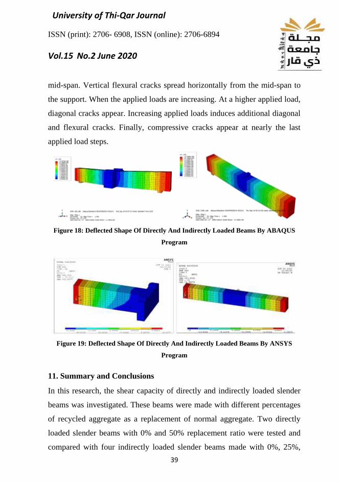
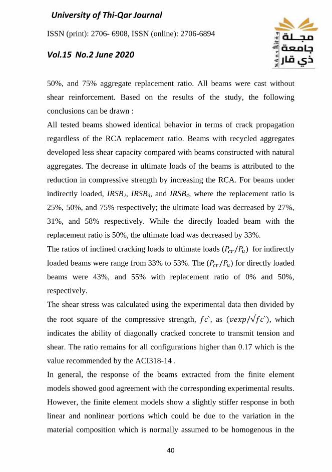
The typical deflected shapes estimated by the programs to the mid-span
deflection at the centerline of cross-section for the direct and indirect loading
were depicted in Figures 18 and 19.
Table 4: The ultimate strength of experimental, Zsutty, ACI-14, and FE results
Beam SN Exp
(kN)
Zsutty
(kN)
A1
(%)
ACI
(kN)
A2
(%)
ANSYS
(kN)
A3
(%)
ABAQUS
(kN)
A4
(%)
Indirectly Loaded RCASCC without Stirrup
ISB1 260 47.2 -82 33.35 -87 265 2 270 4
ISB2 190 46.6 -75 32.63 -83 210 11 200 5
ISB3 180 45.2 -75 31.20 -83 190 6 200 11
ISB4 110 43.3 -61 29.23 -73 120 9 125 14
Directly Loaded without Stirrup and RCA%
DSB1 300 39.40 -87 33.35 -89 305 2 310 3
DSB3 200 37.7 -81 31.20 -84 211 5 220 10
Figure 17: The comparison of the ultimate capacity of experimental, Zsutty, ACI, and
FE results
The crack patterns predicted by the finite element analysis and the failure
modes of experimental specimens agree well. The programs record a crack
pattern at each applied load step. In general, flexural cracks occur early at
A2 =
𝑨𝑪𝑰𝒑𝒖−𝑬𝒙𝒑
𝑬𝒙𝒑
A3=
𝑨𝑵𝑺𝒀𝑺𝒑𝒖−𝑬𝒙𝒑
𝑬𝒙𝒑 A1
=
𝒁𝒔𝒖𝒕𝒕𝒚𝒑𝒖−𝑬𝒙𝒑
𝑬𝒙𝒑
A4=
𝑨𝑩𝑨𝑸𝑼𝑺𝒑𝒖−𝑬𝒙𝒑
𝑬𝒙𝒑
0
50
100
150
200
250
300
350
ISB1 ISB2 ISB3 ISB4 DSB1 DSB3
Ult
imat
e Sh
ear
Str
engt
h (
kN)
ACI (kN) Zsutty Equ. Pu (kN) Exp. Pu (kN) ANSYS (kN) ABAQUS (kN)
University of Thi-Qar Journal
ISSN (print): 2706- 6908, ISSN (online): 2706-6894
Vol.15 No.2 June 2020
39
mid-span. Vertical flexural cracks spread horizontally from the mid-span to
the support. When the applied loads are increasing. At a higher applied load,
diagonal cracks appear. Increasing applied loads induces additional diagonal
and flexural cracks. Finally, compressive cracks appear at nearly the last
applied load steps.
Figure 18: Deflected Shape Of Directly And Indirectly Loaded Beams By ABAQUS
Program
Figure 19: Deflected Shape Of Directly And Indirectly Loaded Beams By ANSYS
Program
11. Summary and Conclusions
In this research, the shear capacity of directly and indirectly loaded slender
beams was investigated. These beams were made with different percentages
of recycled aggregate as a replacement of normal aggregate. Two directly
loaded slender beams with 0% and 50% replacement ratio were tested and
compared with four indirectly loaded slender beams made with 0%, 25%,
University of Thi-Qar Journal
ISSN (print): 2706- 6908, ISSN (online): 2706-6894
Vol.15 No.2 June 2020
40
50%, and 75% aggregate replacement ratio. All beams were cast without
shear reinforcement. Based on the results of the study, the following
conclusions can be drawn :
All tested beams showed identical behavior in terms of crack propagation
regardless of the RCA replacement ratio. Beams with recycled aggregates
developed less shear capacity compared with beams constructed with natural
aggregates. The decrease in ultimate loads of the beams is attributed to the
reduction in compressive strength by increasing the RCA. For beams under
indirectly loaded, IRSB2, IRSB3, and IRSB4, where the replacement ratio is
25%, 50%, and 75% respectively; the ultimate load was decreased by 27%,
31%, and 58% respectively. While the directly loaded beam with the
replacement ratio is 50%, the ultimate load was decreased by 33%.
The ratios of inclined cracking loads to ultimate loads (𝑃𝑐𝑟/𝑃𝑢) for indirectly
loaded beams were range from 33% to 53%. The (𝑃𝑐𝑟/𝑃𝑢) for directly loaded
beams were 43%, and 55% with replacement ratio of 0% and 50%,
respectively.
The shear stress was calculated using the experimental data then divided by
the root square of the compressive strength, 𝑓𝑐`, as (𝑣𝑒𝑥𝑝/√𝑓𝑐`), which
indicates the ability of diagonally cracked concrete to transmit tension and
shear. The ratio remains for all configurations higher than 0.17 which is the
value recommended by the ACI318-14 .
In general, the response of the beams extracted from the finite element
models showed good agreement with the corresponding experimental results.
However, the finite element models show a slightly stiffer response in both
linear and nonlinear portions which could be due to the variation in the
material composition which is normally assumed to be homogenous in the
University of Thi-Qar Journal
ISSN (print): 2706- 6908, ISSN (online): 2706-6894
Vol.15 No.2 June 2020
41
FE models. For example, the ultimate loaded was higher than the
experimental result by 7%.
Mid-span deflection from experimental data was lower than those predicted
by FE models with an average of 6%. The ultimate capacity of beams
predicted by Zsutty and ACI318-14 for ordinary beams is lower than the
experimental results for both directly and indirectly loaded beams.
In general, the comparison between using different softwares is that;
ABAQUS was easier in meshing the models. For same mesh size, ABAQUS
was faster than ANSYS in running and yielding the results. However,
ANSYS provides an easy to visualize crack patron compared with
ABAQUS.
References
[1] Nadir, Wissam, Mohammed K. Dhahir, and Fatimah H. Naser. "A
compression field based model to assess the shear strength of concrete slender
beams without web reinforcement." Case Studies in Construction Materials 9
(2018): e00210.
[2] Alhussein, Thamer Hussein Amer, and Jamal Abdul Samad Khudhair.
"Shear Strength of Directly and Indirectly Loaded Rectangular Self-Compacted
Reinforced Concrete Deep Beams Containing Recycled Concrete as Coarse
Aggregate." Anbar Journal of Engineering Sciences 8.3 (2020): 212-220.
[3] Gonzalez-Fonteboa B and Martınez-Abella F (2007) Shear strength of
recycled concrete beams. Construction and Building Materials 21(4): 887–893.
[4] Gonzalez-Fonteboa B, Martınez-Abella F, and Martınez-Lage I, et al.
(2009) Structural shear behavior of recycled concrete with silica fume.
Construction and Building Materials 23(11): 3406–3410.
[5] Etxeberria M, Mari AR, and Vazquez E (2007) Recycled aggregate concrete
as a structural material. Materials and Structures 40(5): 529–541.
[6] Aqeel H. CH., “PROPERTIES AND STRUCTURAL BEHAVIOR OF
SELF COMPACTING CONCRETE” Ph.D. Thesis University of Basrah,
college of engineering, 2013.
University of Thi-Qar Journal
ISSN (print): 2706- 6908, ISSN (online): 2706-6894
Vol.15 No.2 June 2020
42
[7] ACI-Committee-318 (2014) Building code requirements for structural
concrete (ACI 318-14) and commentary.
[8] Wardeh G, Ghorbel E, Gomart H, et al. (2017) Experimental and analytical
study of bond behavior between recycled aggregate concrete and steel bars
using a pullout test. Structural Concrete. Epub ahead of print 15 June. DOI:
10.1002/suco.201600155.
[9] Ikegawa T, Saito H, Ohuchi H, et al. (2009) Flexural and shear failure tests
of reinforced concrete beams with low grade recycled aggregate. International
Journal of Civil Engineering and Technology 50(12): 29–36.
[10] Hussein Amer Alhussein, Thamer, and Jamal Abdul Samad Khudhair.
"Experimental and Numerical Evaluation of Shear Strength of Directly and
Indirectly Loaded Flanged Recycled Self-Compacted Reinforced Concrete
Deep Beams." Journal of Engineering 2020 (2020).
[11] Ali K. Khtar and Jamal A. Samad Khudair. Experimental Study of the
Shear strength of Self Compacting Concrete T-beams made with Recycled
Concrete as Coarse Aggregate. University of Thi-Qar Journal Vol.14 No.1 Mar
2019.
[12] Emadaldeen A. Sulaiman, Dr. Jamal A. Samad Khudair. Experimental
Study on the Behavior and Strength of Reinforced Concrete Corbels Cast with
Self-Compacting Concrete Incorporating Recycled Concrete as Coarse
Aggregate. International Journal of Civil Engineering and Technology (IJCIET)
Volume 10, Issue 1, January 2019, pp.188–201, Article ID:
IJCIET_10_01_018.
[13] Release 15, ANSYS Guide, ANSYS CFX Solver Modeling. Inc,
Canonsburg, PA2015.
[14] ABAQUS. (2017). ABAQUS/standard version 17.0 user's manuals:
Volume I-III, Hibbitt, Karlsson, and Sorenson, Inc., Pawtucket, RI.
[15] M. J. A. Albraheemi, W. G. Davids, A. Schanck, and S. Tomlinson,
“Evaluation and rating of older non-composite steel girder bridges using field
live load testing and nonlinear finite element analysis,” Bridge Structures, vol.
15, no. 1-2, pp. 27–41, 2019.
وبإستخدام تقنية العناصر المحددة للأعتاب الخرسانية النحيفة حساب مقاومة القص عمليا
وركام معاد تدويره والتي يتم تحميلها بشكل المستطيلة والمصبوبة بإستخدام خرسانة ذاتية الرص
مباشر وغير مباشر
University of Thi-Qar Journal
ISSN (print): 2706- 6908, ISSN (online): 2706-6894
Vol.15 No.2 June 2020
43
، )أ(ثامر حسين عامر الحسين
)ب(أستاذ مساعد دكتور جمال عبد الصمد خضير
)أ(قسم الهندسة المدنية، كلية الهندسة، جامعة البصرة، مرشح الدكتوراه.
)ب( صرة .أ.م.د تدريسي قسم الهندسة المدنية ، كلية الهندسة ، جامعة الب
السلوك الانشائي للأعتاب اجراء دراسة مختبرية وتحليلية تخصإن الهدف الرئيس لهذه الدراسة هو
الخرسانية المسلحة النحيفة بمقطع عرضي على شكل مستطيل، والمعرضة لأحمال بشكل مباشر
، التي تحتوي على قطع صغيرة من (SCC) الرص خرسانة ذاتية باستعمالوغير مباشر،
. تم دراسة الخواص الميكانيكية لأربع (RCA) رسانة المتصلبة المعاد تدويرها كركام خشنالخ
خلطات من حيث مقاومة الانضغاط ، مقاومة الشد )الانشطار( ومعامل المرونة. أظهرت النتائج
التجريبية )العملي( أن مقاومة القص للخرسانة المعاد تدويرها أقل من تلك المصنوعة من الركام
ACI318M-14لطبيعي. تمت مقارنة مقاومات القص التجريبية للأعتاب المفحوصة مختبريا مع ا
النتائج المختبرية ثم قسم على الجذر باستعمالوالدراسات البحثية السابقة، تم حساب إجهاد القص
( مما يشير إلى قدرة الخرسانة المتشققة `𝑣𝑒𝑥𝑝/√𝑓𝑐، مثل ) `𝑓𝑐 التربيعي لمقاومة الانضغاط ،
، وهي 0.17قطريا على نقل اجهادات الشد والقص. بحيث تبقى النسبة لجميع العتبات أعلى من
. تمت مقارنة النتائج من نماذج العناصر المحددة ACI318-14القيمة الدنيا الموصى بها من قبل
لتوصل إلى توافق جيد.غير الخطية مع النتائج التجريبية العملية، وتم ا