Embed Size (px)
Citation preview
Application Note 11
_____________________________________________________________________________________________________ Application Note 11
© ibidi GmbH, Version 4.1, 29 March 2016 Page 1 of 16
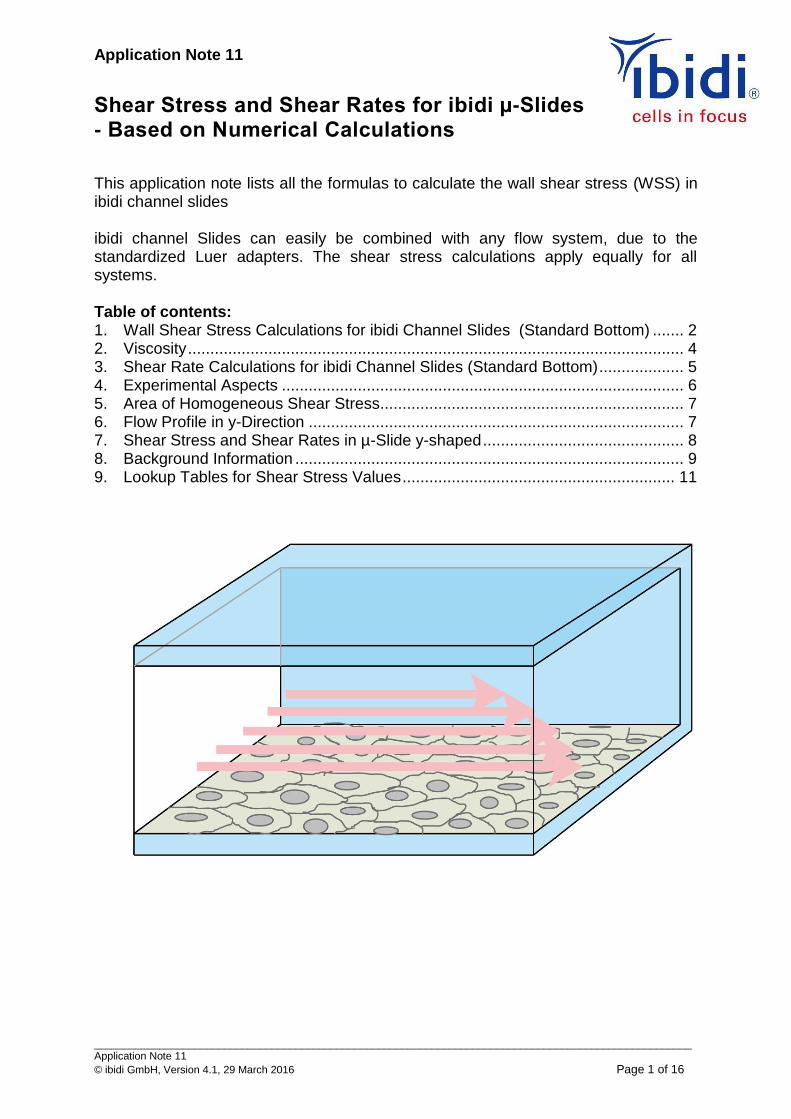
Shear Stress and Shear Rates for ibidi µ-Slides - Based on Numerical Calculations
This application note lists all the formulas to calculate the wall shear stress (WSS) in ibidi channel slides ibidi channel Slides can easily be combined with any flow system, due to the standardized Luer adapters. The shear stress calculations apply equally for all systems. Table of contents: 1. Wall Shear Stress Calculations for ibidi Channel Slides (Standard Bottom) ....... 2
2. Viscosity ............................................................................................................... 4 3. Shear Rate Calculations for ibidi Channel Slides (Standard Bottom) ................... 5
4. Experimental Aspects .......................................................................................... 6
5. Area of Homogeneous Shear Stress.................................................................... 7 6. Flow Profile in y-Direction .................................................................................... 7 7. Shear Stress and Shear Rates in µ-Slide y-shaped ............................................. 8
8. Background Information ....................................................................................... 9 9. Lookup Tables for Shear Stress Values ............................................................. 11
Application Note 11
_____________________________________________________________________________________________________ Application Note 11
© ibidi GmbH, Version 4.1, 29 March 2016 Page 2 of 16
1. Wall Shear Stress Calculations for ibidi Channel Slides (Standard Bottom)
For simplicity reasons the calculations include all conversions of units (not shown). To calculate the wall shear stress correctly, you must know the viscosity of the perfused medium. In section 2 you will find more information about the viscosity determination.
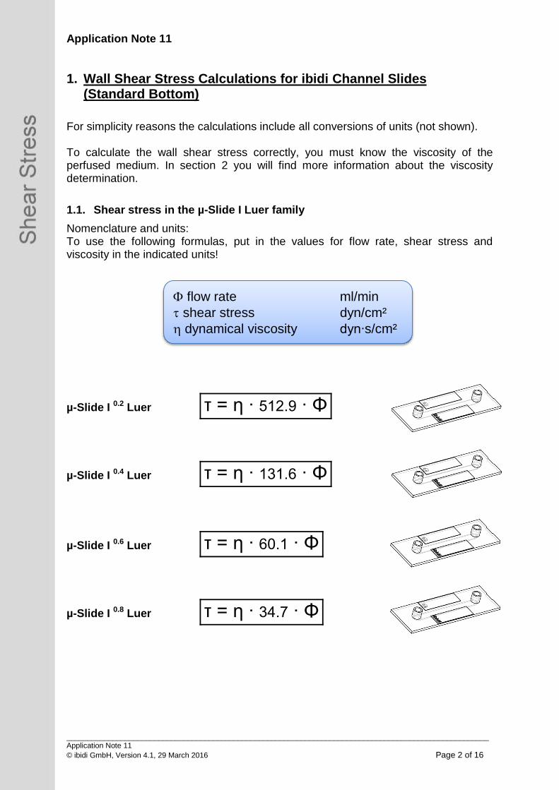
1.1. Shear stress in the µ-Slide I Luer family
Nomenclature and units: To use the following formulas, put in the values for flow rate, shear stress and viscosity in the indicated units!
µ-Slide I 0.2 Luer τ = η ∙ 512.9 ∙ Φ
µ-Slide I 0.4 Luer τ = η ∙ 131.6 ∙ Φ
µ-Slide I 0.6 Luer τ = η ∙ 60.1 ∙ Φ
µ-Slide I 0.8 Luer τ = η ∙ 34.7 ∙ Φ
flow rate ml/min
shear stress dyn/cm²
dynamical viscosity dyn∙s/cm²
Application Note 11
_____________________________________________________________________________________________________ Application Note 11
© ibidi GmbH, Version 4.1, 29 March 2016 Page 3 of 16
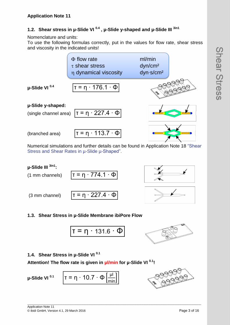
1.2. Shear stress in µ-Slide VI 0.4 , µ-Slide y-shaped and µ-Slide III 3in1
Nomenclature and units: To use the following formulas correctly, put in the values for flow rate, shear stress and viscosity in the indicated units!
µ-Slide VI 0.4 τ = η ∙ 176.1 ∙ Φ
µ-Slide y-shaped:
(single channel area) τ = η ∙ 227.4 ∙ Φ
(branched area) τ = η ∙ 113.7 ∙ Φ
Numerical simulations and further details can be found in Application Note 18 “Shear Stress and Shear Rates in µ-Slide µ-Shaped”. µ-Slide III 3in1:
(1 mm channels) τ = η ∙ 774.1 ∙ Φ
(3 mm channel) τ = η ∙ 227.4 ∙ Φ
1.3. Shear Stress in µ-Slide Membrane ibiPore Flow
τ = η ∙ 131.6 ∙ Φ
1.4. Shear Stress in µ-Slide VI 0.1
Attention! The flow rate is given in µl/min for µ-Slide VI 0.1!
µ-Slide VI 0.1 τ = η ∙ 10.7 ∙ Φ [µl
min]
flow rate ml/min
shear stress dyn/cm²
dynamical viscosity dyn∙s/cm²
Application Note 11
_____________________________________________________________________________________________________ Application Note 11
© ibidi GmbH, Version 4.1, 29 March 2016 Page 4 of 16
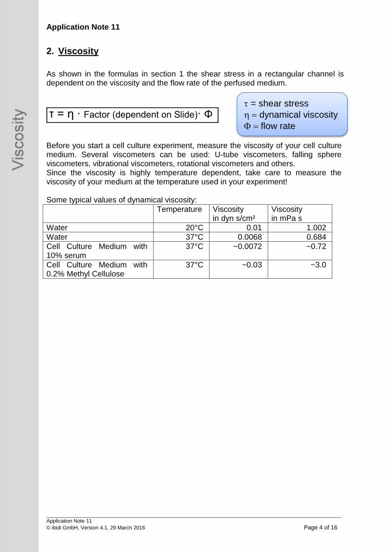
2. Viscosity
As shown in the formulas in section 1 the shear stress in a rectangular channel is dependent on the viscosity and the flow rate of the perfused medium.
τ = η ∙ Factor (dependent on Slide)∙ Φ
Before you start a cell culture experiment, measure the viscosity of your cell culture medium. Several viscometers can be used: U-tube viscometers, falling sphere viscometers, vibrational viscometers, rotational viscometers and others. Since the viscosity is highly temperature dependent, take care to measure the viscosity of your medium at the temperature used in your experiment! Some typical values of dynamical viscosity:
Temperature Viscosity in dyn s/cm²
Viscosity in mPa s
Water 20°C 0.01 1.002
Water 37°C 0.0068 0.684
Cell Culture Medium with 10% serum
37°C ~0.0072 ~0.72
Cell Culture Medium with 0.2% Methyl Cellulose
37°C ~0.03 ~3.0
= shear stress
dynamical viscosity
flow rate
Application Note 11
_____________________________________________________________________________________________________ Application Note 11
© ibidi GmbH, Version 4.1, 29 March 2016 Page 5 of 16
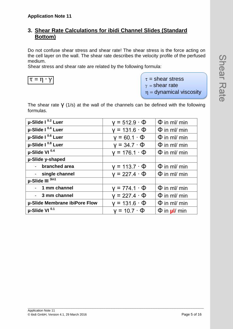
3. Shear Rate Calculations for ibidi Channel Slides (Standard Bottom)
Do not confuse shear stress and shear rate! The shear stress is the force acting on the cell layer on the wall. The shear rate describes the velocity profile of the perfused medium. Shear stress and shear rate are related by the following formula:
τ = η ∙ γ
The shear rate γ (1/s) at the wall of the channels can be defined with the following
formulas.
µ-Slide I 0.2 Luer γ = 512.9 ∙ Φ Φ in ml/ min
µ-Slide I 0.4 Luer γ = 131.6 ∙ Φ Φ in ml/ min
µ-Slide I 0.6 Luer γ = 60.1 ∙ Φ Φ in ml/ min
µ-Slide I 0.8 Luer γ = 34.7 ∙ Φ Φ in ml/ min
µ-Slide VI 0.4 γ = 176.1 ∙ Φ Φ in ml/ min
µ-Slide y-shaped
- branched area γ = 113.7 ∙ Φ Φ in ml/ min
- single channel γ = 227.4 ∙ Φ Φ in ml/ min µ-Slide III 3in1
- 1 mm channel γ = 774.1 ∙ Φ Φ in ml/ min
- 3 mm channel γ = 227.4 ∙ Φ Φ in ml/ min
µ-Slide Membrane ibiPore Flow γ = 131.6 ∙ Φ Φ in ml/ min µ-Slide VI 0.1 γ = 10.7 ∙ Φ Φ in µl/ min
= shear stress shear rate
dynamical viscosity
Application Note 11
_____________________________________________________________________________________________________ Application Note 11
© ibidi GmbH, Version 4.1, 29 March 2016 Page 6 of 16
4. Experimental Aspects
In order to set up the right experiment you first should define the following parameters of your experiment:
• Cell type • Shear stress (tissue and species specific) • Medium and viscosity of the needed medium • Available volume • Available amount of cells • Duration of the experiment • Flow characteristics (continuous, one way, oscillating…) • Needed number of cells for downstream applications • Coating of the surface (cell type dependent) • More experimental details, e.g. addition of substances, time points of
measurements • Experimental endpoints
Choosing the right slide The selection of the slide determines the range of shear stress that can be applied, depending on the flow rate, by the respective pump. Generally the following rules-of-thumb can be applied:
• A small channel favours the generation of high shear stress values. • A large channel favours the generation low shear stress values.
Based on the options of your pump, you can calculate which range of shear stress you will be able to apply. Choosing the right flow rate Define the shear stress for your experimental setup. Once you have chosen a slide you can determine the required flow rate to achieve the desired shear stress as given by the formulas in this Application Note. Choosing the right perfusion system (pump) Depending on setup specifications (duration, volume, flow characteristics…) different pumps are optimal. For long term cultivation (e.g. endothelial cell conditioning under flow) we recommend the ibidi Pump System.
Application Note 11
_____________________________________________________________________________________________________ Application Note 11
© ibidi GmbH, Version 4.1, 29 March 2016 Page 7 of 16
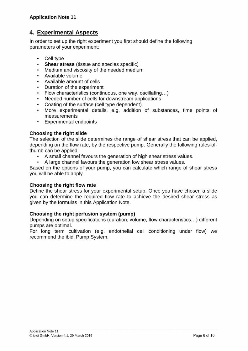
5. Area of Homogeneous Shear Stress
All shear stress calculations are only valid in regions away from the walls (see orange area below). Side effects near the wall are ignored. Observations should be done in a distance away from the walls comparable to the channel height. For example, if the channel has a height of 400 µm the observation area showing a homogeneous flow profile will be about 400 µm from the side walls in the center region of the channel (orange area).
6. Flow Profile in y-Direction
All our channel slides are characterized by parabola shaped flow profiles in the y-direction. The flow profile inside µ-Slide I 0.4 Luer is shown below.
Application Note 11
_____________________________________________________________________________________________________ Application Note 11
© ibidi GmbH, Version 4.1, 29 March 2016 Page 8 of 16
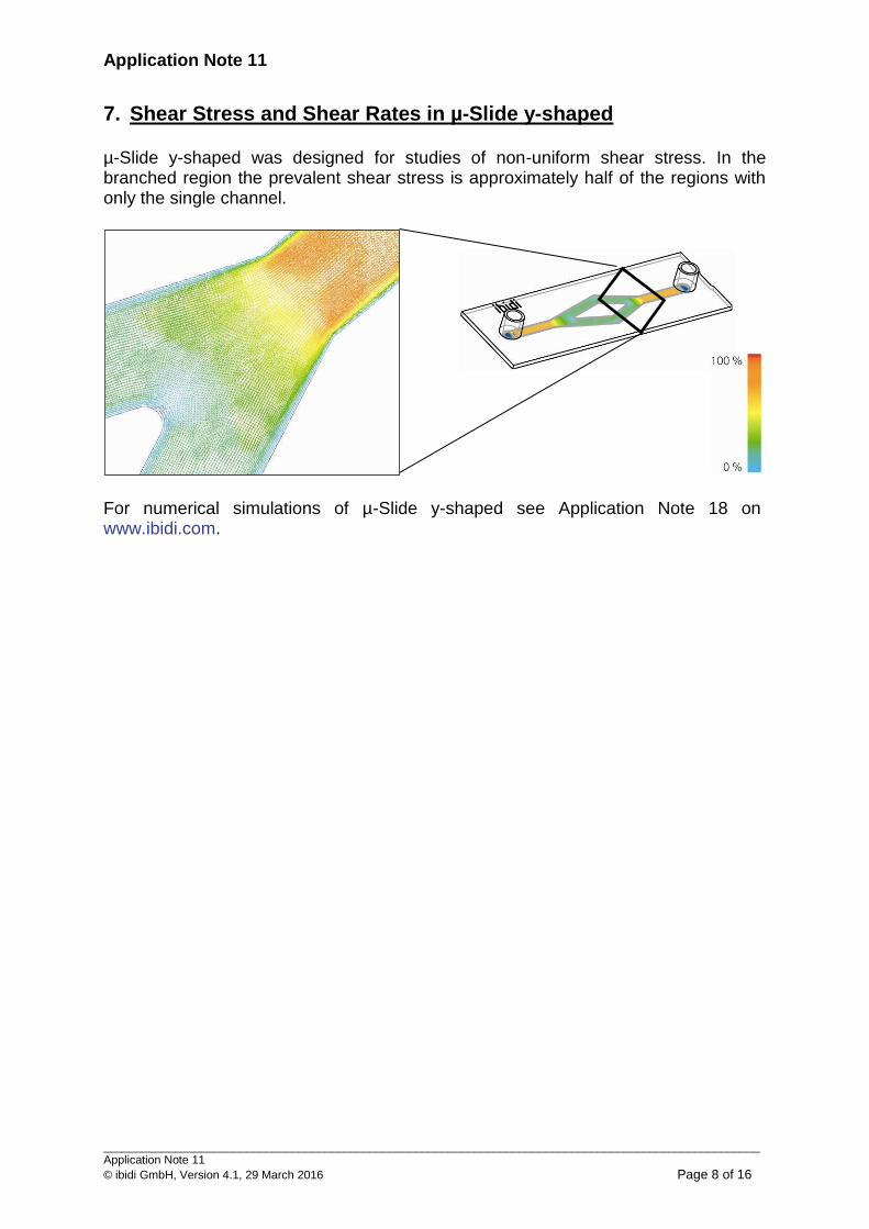
7. Shear Stress and Shear Rates in µ-Slide y-shaped
µ-Slide y-shaped was designed for studies of non-uniform shear stress. In the branched region the prevalent shear stress is approximately half of the regions with only the single channel.
For numerical simulations of µ-Slide y-shaped see Application Note 18 on www.ibidi.com.
Application Note 11
_____________________________________________________________________________________________________ Application Note 11
© ibidi GmbH, Version 4.1, 29 March 2016 Page 9 of 16
8. Background Information
The local flow velocity v(x,y) is calculated by (Cornish 1928)1):
0
3
3
222
2
)12(cos
2)12(cosh
2)12(cosh
2
)12(
)2()1(
22
1),(
n
n
b
xn
b
hn
b
yn
n
bxb
dz
dpyxv
The total flow through the channel is calculated by1):
05
5
43
2
)12(tanh
)12(
128
3
41
n b
hn
nbbh
dz
dp
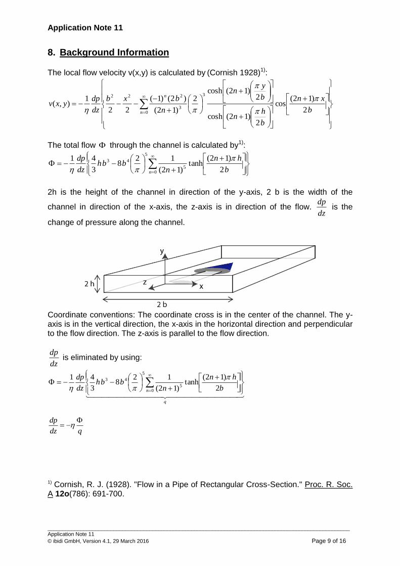
2h is the height of the channel in direction of the y-axis, 2 b is the width of the
channel in direction of the x-axis, the z-axis is in direction of the flow. dz
dp is the
change of pressure along the channel.
Coordinate conventions: The coordinate cross is in the center of the channel. The y-axis is in the vertical direction, the x-axis in the horizontal direction and perpendicular to the flow direction. The z-axis is parallel to the flow direction.
dz
dp is eliminated by using:
q
n b
hn
nbbh
dz
dp
05
5
43
2
)12(tanh
)12(
128
3
41
qdz
dp
1) Cornish, R. J. (1928). "Flow in a Pipe of Rectangular Cross-Section." Proc. R. Soc. A 12o(786): 691-700.
Application Note 11
_____________________________________________________________________________________________________ Application Note 11
© ibidi GmbH, Version 4.1, 29 March 2016 Page 10 of 16
Shear stress is calculated using the relation
hy
n
n
hyb
xn
b
hn
b
yn
n
b
dz
dp
y
yxvyx
0
3
2 2
)12(cos
2)12(cosh
2)12(sinh
2
)12(
)1(1),(),(
Elimination of dz
dp gives:
hy
n
n
b
xn
b
hn
b
yn
n
b
qyx
0
3
2 2
)12(cos
2)12(cosh
2)12(sinh
2
)12(
)1(1),(
hy
n
n
b
xn
b
hn
b
yn
n
b
q
0
3
2 2
)12(cos
2)12(cosh
2)12(sinh
2
)12(
)1(
The cells typically attach to the bottom of the channel. The wall shear stress at the
bottom of the channel (y=-h) and at the center of the channel (x=0) is:
0
3
2 2)12(tanh
2
)12(
)1(),0(
n
n
b
hn
n
b
qhyx
Application Note 11
_____________________________________________________________________________________________________ Application Note 11
© ibidi GmbH, Version 4.1, 29 March 2016 Page 11 of 16
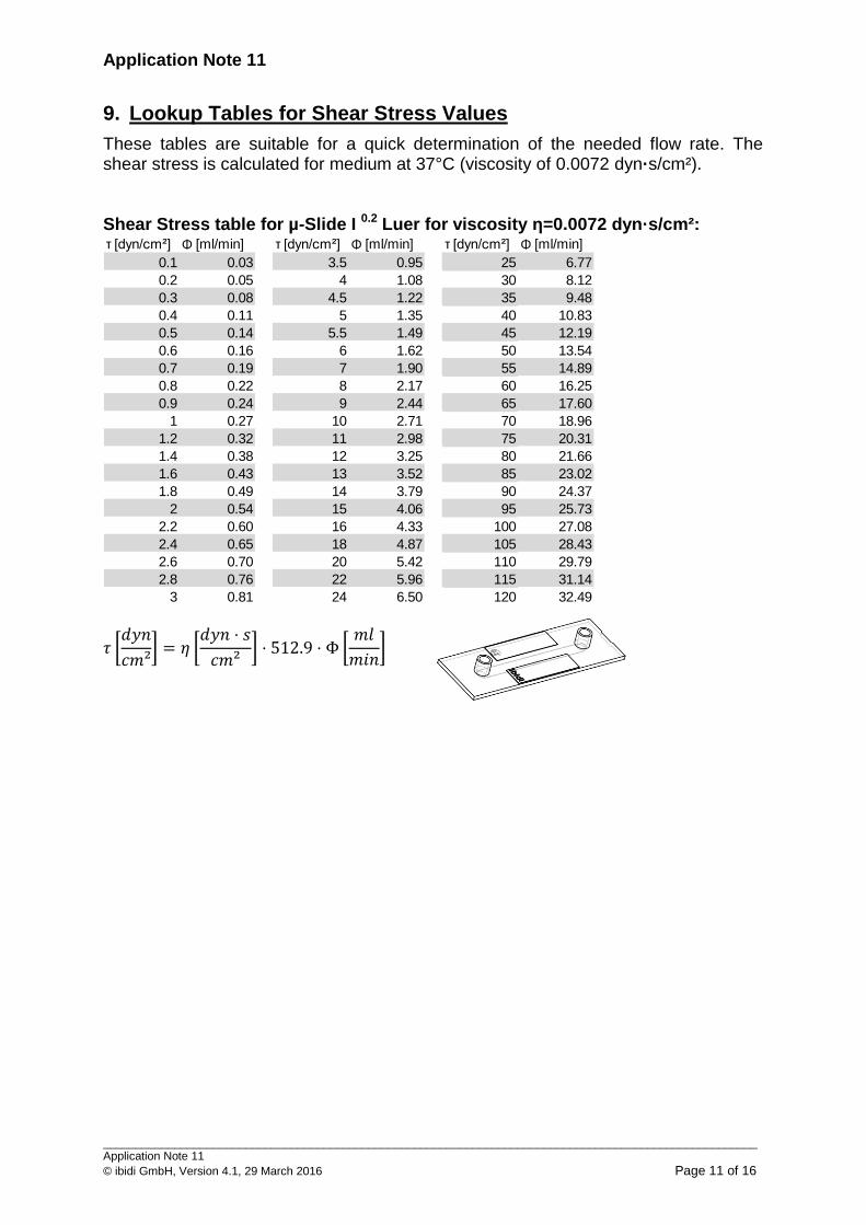
9. Lookup Tables for Shear Stress Values
These tables are suitable for a quick determination of the needed flow rate. The shear stress is calculated for medium at 37°C (viscosity of 0.0072 dyn·s/cm²). Shear Stress table for µ-Slide I 0.2 Luer for viscosity η=0.0072 dyn·s/cm²:
𝜏 [𝑑𝑦𝑛
𝑐𝑚²] = 𝜂 [
𝑑𝑦𝑛 ⋅ 𝑠
𝑐𝑚²] ⋅ 512.9 ⋅ Φ [
𝑚𝑙
𝑚𝑖𝑛]
τ [dyn/cm²] Φ [ml/min] τ [dyn/cm²] Φ [ml/min] τ [dyn/cm²] Φ [ml/min]
0.1 0.03 3.5 0.95 25 6.77
0.2 0.05 4 1.08 30 8.12
0.3 0.08 4.5 1.22 35 9.48
0.4 0.11 5 1.35 40 10.83
0.5 0.14 5.5 1.49 45 12.19
0.6 0.16 6 1.62 50 13.54
0.7 0.19 7 1.90 55 14.89
0.8 0.22 8 2.17 60 16.25
0.9 0.24 9 2.44 65 17.60
1 0.27 10 2.71 70 18.96
1.2 0.32 11 2.98 75 20.31
1.4 0.38 12 3.25 80 21.66
1.6 0.43 13 3.52 85 23.02
1.8 0.49 14 3.79 90 24.37
2 0.54 15 4.06 95 25.73
2.2 0.60 16 4.33 100 27.08
2.4 0.65 18 4.87 105 28.43
2.6 0.70 20 5.42 110 29.79
2.8 0.76 22 5.96 115 31.14
3 0.81 24 6.50 120 32.49

Application Note 11
_____________________________________________________________________________________________________ Application Note 11
© ibidi GmbH, Version 4.1, 29 March 2016 Page 12 of 16
Shear Stress table for µ-Slide I 0.4 Luer for viscosity η=0.0072 dyn·s/cm²:
𝜏 [𝑑𝑦𝑛
𝑐𝑚²] = 𝜂 [
𝑑𝑦𝑛 ⋅ 𝑠
𝑐𝑚²] ⋅ 131.6 ⋅ Φ [
𝑚𝑙
𝑚𝑖𝑛]
Shear Stress table for µ-Slide I 0.6 Luer for viscosity η=0.0072 dyn·s/cm²:
𝜏 [𝑑𝑦𝑛
𝑐𝑚²] = 𝜂 [
𝑑𝑦𝑛 ⋅ 𝑠
𝑐𝑚²] ⋅ 60.1 ⋅ Φ [
𝑚𝑙
𝑚𝑖𝑛]
τ [dyn/cm²] Φ [ml/min] τ [dyn/cm²] Φ [ml/min] τ [dyn/cm²] Φ [ml/min]
0.1 0.11 3.5 3.69 25 26.38
0.2 0.21 4 4.22 30 31.66
0.3 0.32 4.5 4.75 35 36.94
0.4 0.42 5 5.28 40 42.22
0.5 0.53 5.5 5.80 45 47.49
0.6 0.63 6 6.33 50 52.77
0.7 0.74 7 7.39 55 58.05
0.8 0.84 8 8.44 60 63.32
0.9 0.95 9 9.50 65 68.60
1 1.06 10 10.55 70 73.88
1.2 1.27 11 11.61 75 79.15
1.4 1.48 12 12.66 80 84.43
1.6 1.69 13 13.72 85 89.71
1.8 1.90 14 14.78 90 94.98
2 2.11 15 15.83 95 100.26
2.2 2.32 16 16.89 100 105.54
2.4 2.53 18 19.00 105 110.82
2.6 2.74 20 21.11 110 116.09
2.8 2.96 22 23.22 115 121.37
3 3.17 24 25.33 120 126.65
τ [dyn/cm²] Φ [ml/min] τ [dyn/cm²] Φ [ml/min] τ [dyn/cm²] Φ [ml/min]
0.1 0.23 3.5 8.09 25 57.77
0.2 0.46 4 9.24 30 69.33
0.3 0.69 4.5 10.40 35 80.88
0.4 0.92 5 11.55 40 92.44
0.5 1.16 5.5 12.71 45 103.99
0.6 1.39 6 13.87 50 115.55
0.7 1.62 7 16.18 55 127.10
0.8 1.85 8 18.49 60 138.66
0.9 2.08 9 20.80 65 150.21
1 2.31 10 23.11 70 161.77
1.2 2.77 11 25.42 75 173.32
1.4 3.24 12 27.73 80 184.88
1.6 3.70 13 30.04 85 196.43
1.8 4.16 14 32.35 90 207.99
2 4.62 15 34.66 95 219.54
2.2 5.08 16 36.98 100 231.10
2.4 5.55 18 41.60 105 242.65
2.6 6.01 20 46.22 110 254.21
2.8 6.47 22 50.84 115 265.76
3 6.93 24 55.46 120 277.32
Application Note 11
_____________________________________________________________________________________________________ Application Note 11
© ibidi GmbH, Version 4.1, 29 March 2016 Page 13 of 16
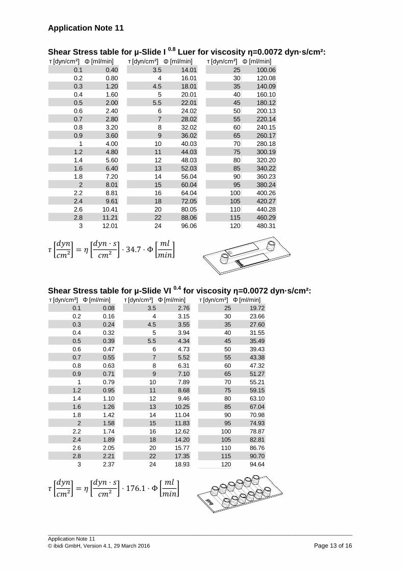
Shear Stress table for µ-Slide I 0.8 Luer for viscosity η=0.0072 dyn·s/cm²:
𝜏 [𝑑𝑦𝑛
𝑐𝑚²] = 𝜂 [
𝑑𝑦𝑛 ⋅ 𝑠
𝑐𝑚²] ⋅ 34.7 ⋅ Φ [
𝑚𝑙
𝑚𝑖𝑛]
Shear Stress table for µ-Slide VI 0.4 for viscosity η=0.0072 dyn·s/cm²:
𝜏 [𝑑𝑦𝑛
𝑐𝑚²] = 𝜂 [
𝑑𝑦𝑛 ⋅ 𝑠
𝑐𝑚²] ⋅ 176.1 ⋅ Φ [
𝑚𝑙
𝑚𝑖𝑛]
τ [dyn/cm²] Φ [ml/min] τ [dyn/cm²] Φ [ml/min] τ [dyn/cm²] Φ [ml/min]
0.1 0.40 3.5 14.01 25 100.06
0.2 0.80 4 16.01 30 120.08
0.3 1.20 4.5 18.01 35 140.09
0.4 1.60 5 20.01 40 160.10
0.5 2.00 5.5 22.01 45 180.12
0.6 2.40 6 24.02 50 200.13
0.7 2.80 7 28.02 55 220.14
0.8 3.20 8 32.02 60 240.15
0.9 3.60 9 36.02 65 260.17
1 4.00 10 40.03 70 280.18
1.2 4.80 11 44.03 75 300.19
1.4 5.60 12 48.03 80 320.20
1.6 6.40 13 52.03 85 340.22
1.8 7.20 14 56.04 90 360.23
2 8.01 15 60.04 95 380.24
2.2 8.81 16 64.04 100 400.26
2.4 9.61 18 72.05 105 420.27
2.6 10.41 20 80.05 110 440.28
2.8 11.21 22 88.06 115 460.29
3 12.01 24 96.06 120 480.31
τ [dyn/cm²] Φ [ml/min] τ [dyn/cm²] Φ [ml/min] τ [dyn/cm²] Φ [ml/min]
0.1 0.08 3.5 2.76 25 19.72
0.2 0.16 4 3.15 30 23.66
0.3 0.24 4.5 3.55 35 27.60
0.4 0.32 5 3.94 40 31.55
0.5 0.39 5.5 4.34 45 35.49
0.6 0.47 6 4.73 50 39.43
0.7 0.55 7 5.52 55 43.38
0.8 0.63 8 6.31 60 47.32
0.9 0.71 9 7.10 65 51.27
1 0.79 10 7.89 70 55.21
1.2 0.95 11 8.68 75 59.15
1.4 1.10 12 9.46 80 63.10
1.6 1.26 13 10.25 85 67.04
1.8 1.42 14 11.04 90 70.98
2 1.58 15 11.83 95 74.93
2.2 1.74 16 12.62 100 78.87
2.4 1.89 18 14.20 105 82.81
2.6 2.05 20 15.77 110 86.76
2.8 2.21 22 17.35 115 90.70
3 2.37 24 18.93 120 94.64

Application Note 11
_____________________________________________________________________________________________________ Application Note 11
© ibidi GmbH, Version 4.1, 29 March 2016 Page 14 of 16
Shear Stress table for µ-Slide y-shaped for viscosity η=0.0072 dyn·s/cm² (single channel area):
𝜏 [𝑑𝑦𝑛
𝑐𝑚²] = 𝜂 [
𝑑𝑦𝑛 ⋅ 𝑠
𝑐𝑚²] ⋅ 227.4 ⋅ Φ [
𝑚𝑙
𝑚𝑖𝑛]
Shear Stress table for µ-Slide y-shaped for viscosity η=0.0072 dyn·s/cm² (branched channel area):
𝜏 [𝑑𝑦𝑛
𝑐𝑚²] = 𝜂 [
𝑑𝑦𝑛 ⋅ 𝑠
𝑐𝑚²] ⋅ 113.7 ⋅ Φ [
𝑚𝑙
𝑚𝑖𝑛]
τ [dyn/cm²] Φ [ml/min] τ [dyn/cm²] Φ [ml/min] τ [dyn/cm²] Φ [ml/min]
0.1 0.06 3.5 2.14 25 15.27
0.2 0.12 4 2.44 30 18.32
0.3 0.18 4.5 2.75 35 21.38
0.4 0.24 5 3.05 40 24.43
0.5 0.31 5.5 3.36 45 27.48
0.6 0.37 6 3.66 50 30.54
0.7 0.43 7 4.28 55 33.59
0.8 0.49 8 4.89 60 36.65
0.9 0.55 9 5.50 65 39.70
1 0.61 10 6.11 70 42.75
1.2 0.73 11 6.72 75 45.81
1.4 0.86 12 7.33 80 48.86
1.6 0.98 13 7.94 85 51.92
1.8 1.10 14 8.55 90 54.97
2 1.22 15 9.16 95 58.02
2.2 1.34 16 9.77 100 61.08
2.4 1.47 18 10.99 105 64.13
2.6 1.59 20 12.22 110 67.18
2.8 1.71 22 13.44 115 70.24
3 1.83 24 14.66 120 73.29
τ [dyn/cm²] Φ [ml/min] τ [dyn/cm²] Φ [ml/min] τ [dyn/cm²] Φ [ml/min]
0.1 0.12 3.5 4.28 25 30.54
0.2 0.24 4 4.89 30 36.65
0.3 0.37 4.5 5.50 35 42.75
0.4 0.49 5 6.11 40 48.86
0.5 0.61 5.5 6.72 45 54.97
0.6 0.73 6 7.33 50 61.08
0.7 0.86 7 8.55 55 67.18
0.8 0.98 8 9.77 60 73.29
0.9 1.10 9 10.99 65 79.40
1 1.22 10 12.22 70 85.51
1.2 1.47 11 13.44 75 91.62
1.4 1.71 12 14.66 80 97.72
1.6 1.95 13 15.88 85 103.83
1.8 2.20 14 17.10 90 109.94
2 2.44 15 18.32 95 116.05
2.2 2.69 16 19.54 100 122.15
2.4 2.93 18 21.99 105 128.26
2.6 3.18 20 24.43 110 134.37
2.8 3.42 22 26.87 115 140.48
3 3.66 24 29.32 120 146.58
Application Note 11
_____________________________________________________________________________________________________ Application Note 11
© ibidi GmbH, Version 4.1, 29 March 2016 Page 15 of 16
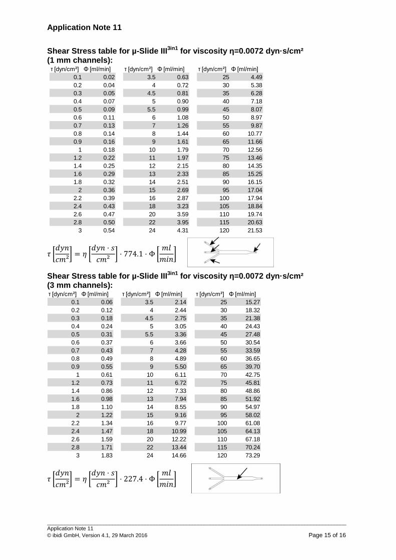
Shear Stress table for µ-Slide III3in1 for viscosity η=0.0072 dyn·s/cm² (1 mm channels):
𝜏 [𝑑𝑦𝑛
𝑐𝑚²] = 𝜂 [
𝑑𝑦𝑛 ⋅ 𝑠
𝑐𝑚²] ⋅ 774.1 ⋅ Φ [
𝑚𝑙
𝑚𝑖𝑛]
Shear Stress table for µ-Slide III3in1 for viscosity η=0.0072 dyn·s/cm² (3 mm channels):
𝜏 [𝑑𝑦𝑛
𝑐𝑚²] = 𝜂 [
𝑑𝑦𝑛 ⋅ 𝑠
𝑐𝑚²] ⋅ 227.4 ⋅ Φ [
𝑚𝑙
𝑚𝑖𝑛]
τ [dyn/cm²] Φ [ml/min] τ [dyn/cm²] Φ [ml/min] τ [dyn/cm²] Φ [ml/min]
0.1 0.02 3.5 0.63 25 4.49
0.2 0.04 4 0.72 30 5.38
0.3 0.05 4.5 0.81 35 6.28
0.4 0.07 5 0.90 40 7.18
0.5 0.09 5.5 0.99 45 8.07
0.6 0.11 6 1.08 50 8.97
0.7 0.13 7 1.26 55 9.87
0.8 0.14 8 1.44 60 10.77
0.9 0.16 9 1.61 65 11.66
1 0.18 10 1.79 70 12.56
1.2 0.22 11 1.97 75 13.46
1.4 0.25 12 2.15 80 14.35
1.6 0.29 13 2.33 85 15.25
1.8 0.32 14 2.51 90 16.15
2 0.36 15 2.69 95 17.04
2.2 0.39 16 2.87 100 17.94
2.4 0.43 18 3.23 105 18.84
2.6 0.47 20 3.59 110 19.74
2.8 0.50 22 3.95 115 20.63
3 0.54 24 4.31 120 21.53
τ [dyn/cm²] Φ [ml/min] τ [dyn/cm²] Φ [ml/min] τ [dyn/cm²] Φ [ml/min]
0.1 0.06 3.5 2.14 25 15.27
0.2 0.12 4 2.44 30 18.32
0.3 0.18 4.5 2.75 35 21.38
0.4 0.24 5 3.05 40 24.43
0.5 0.31 5.5 3.36 45 27.48
0.6 0.37 6 3.66 50 30.54
0.7 0.43 7 4.28 55 33.59
0.8 0.49 8 4.89 60 36.65
0.9 0.55 9 5.50 65 39.70
1 0.61 10 6.11 70 42.75
1.2 0.73 11 6.72 75 45.81
1.4 0.86 12 7.33 80 48.86
1.6 0.98 13 7.94 85 51.92
1.8 1.10 14 8.55 90 54.97
2 1.22 15 9.16 95 58.02
2.2 1.34 16 9.77 100 61.08
2.4 1.47 18 10.99 105 64.13
2.6 1.59 20 12.22 110 67.18
2.8 1.71 22 13.44 115 70.24
3 1.83 24 14.66 120 73.29
Application Note 11
_____________________________________________________________________________________________________ Application Note 11
© ibidi GmbH, Version 4.1, 29 March 2016 Page 16 of 16
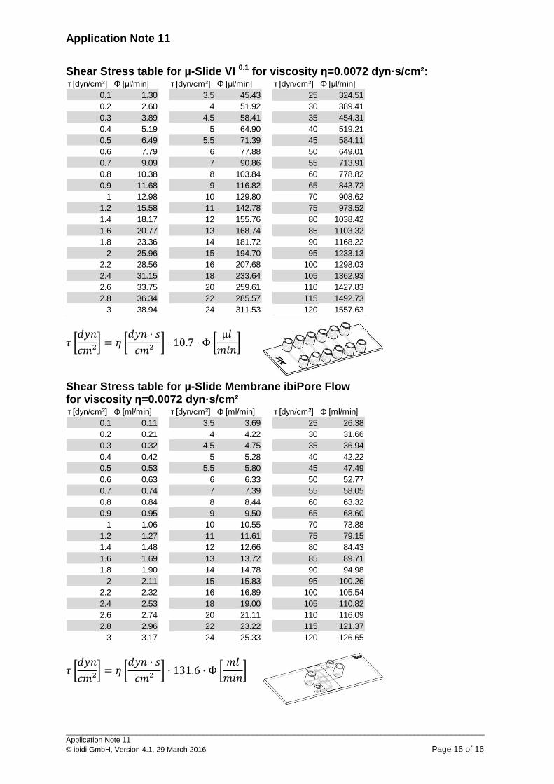
Shear Stress table for µ-Slide VI 0.1 for viscosity η=0.0072 dyn·s/cm²:
𝜏 [𝑑𝑦𝑛
𝑐𝑚²] = 𝜂 [
𝑑𝑦𝑛 ⋅ 𝑠
𝑐𝑚²] ⋅ 10.7 ⋅ Φ [
µ𝑙
𝑚𝑖𝑛]
Shear Stress table for µ-Slide Membrane ibiPore Flow for viscosity η=0.0072 dyn·s/cm²
𝜏 [𝑑𝑦𝑛
𝑐𝑚²] = 𝜂 [
𝑑𝑦𝑛 ⋅ 𝑠
𝑐𝑚²] ⋅ 131.6 ⋅ Φ [
𝑚𝑙
𝑚𝑖𝑛]
τ [dyn/cm²] Φ [µl/min] τ [dyn/cm²] Φ [µl/min] τ [dyn/cm²] Φ [µl/min]
0.1 1.30 3.5 45.43 25 324.51
0.2 2.60 4 51.92 30 389.41
0.3 3.89 4.5 58.41 35 454.31
0.4 5.19 5 64.90 40 519.21
0.5 6.49 5.5 71.39 45 584.11
0.6 7.79 6 77.88 50 649.01
0.7 9.09 7 90.86 55 713.91
0.8 10.38 8 103.84 60 778.82
0.9 11.68 9 116.82 65 843.72
1 12.98 10 129.80 70 908.62
1.2 15.58 11 142.78 75 973.52
1.4 18.17 12 155.76 80 1038.42
1.6 20.77 13 168.74 85 1103.32
1.8 23.36 14 181.72 90 1168.22
2 25.96 15 194.70 95 1233.13
2.2 28.56 16 207.68 100 1298.03
2.4 31.15 18 233.64 105 1362.93
2.6 33.75 20 259.61 110 1427.83
2.8 36.34 22 285.57 115 1492.73
3 38.94 24 311.53 120 1557.63
τ [dyn/cm²] Φ [ml/min] τ [dyn/cm²] Φ [ml/min] τ [dyn/cm²] Φ [ml/min]
0.1 0.11 3.5 3.69 25 26.38
0.2 0.21 4 4.22 30 31.66
0.3 0.32 4.5 4.75 35 36.94
0.4 0.42 5 5.28 40 42.22
0.5 0.53 5.5 5.80 45 47.49
0.6 0.63 6 6.33 50 52.77
0.7 0.74 7 7.39 55 58.05
0.8 0.84 8 8.44 60 63.32
0.9 0.95 9 9.50 65 68.60
1 1.06 10 10.55 70 73.88
1.2 1.27 11 11.61 75 79.15
1.4 1.48 12 12.66 80 84.43
1.6 1.69 13 13.72 85 89.71
1.8 1.90 14 14.78 90 94.98
2 2.11 15 15.83 95 100.26
2.2 2.32 16 16.89 100 105.54
2.4 2.53 18 19.00 105 110.82
2.6 2.74 20 21.11 110 116.09
2.8 2.96 22 23.22 115 121.37
3 3.17 24 25.33 120 126.65


![SENSACIà N, PERCEPCIà N Y RAZONAMIENTOS€¦ · ï µ o µ W ] v µ o µ o µ v o µ À ] À µ v ] v ] À ] µ } } v ] µ Ç ^ µ _ µ](https://img.pdfslide.net/doc/110x75/6032fd624538023875270df3/sensacif-n-percepcif-n-y-razonamientos-o-w-v-o-o-v-o-.jpg)


![} µ K P v ] ] } v } u u µ v µ ' v r µ Z > µ Æ u } µ P · } µ K P v ] ] } v } u u µ v µ ' v r µ Z > µ Æ u } µ P ... ¦ x](https://img.pdfslide.net/doc/110x75/5ea5cf6950ba7a69c11bffc3/-k-p-v-v-u-u-v-v-r-z-u-p-k-p-v-.jpg)

![Visual FoxPro · µ¦µ ° x \ z x µ »£µ¡ o°¥ ´ ¦r £µ Á¦¸¥ ¸ É z z ] ^ y æ Á¦¸¥ »Ã ´¥ª· ¥µ ¤ µ¦µ ° x \ y ] µ £¦ ¸ ´ ªµ¨ £µ Á¦¸¥](https://img.pdfslide.net/doc/110x75/5e9a8f84e4b3f621a5474f89/visual-x-z-x-o-r-z-z-.jpg)


![1. Excel. µ file- µ « . µ µ µ µ µ µ µ µ ; µµ ; µµ µ Excel Word; µ µ µµ ;[ ] µ , µ µ µ](https://img.pdfslide.net/doc/110x75/5e1c0fbb3625a8105f7711f5/1-excel-excel-word-.jpg)
![µ o ( ] v o µ ] µ o µ u µ o µ ] µ v ] À ]](https://img.pdfslide.net/doc/110x75/618d619c813e4d1ea159d154/-o-v-o-o-u-o-v-.jpg)