Embed Size (px)
Citation preview
Department of Structural Mechanics
Faculty of Civil Engineering, VSB - Technical University Ostrava
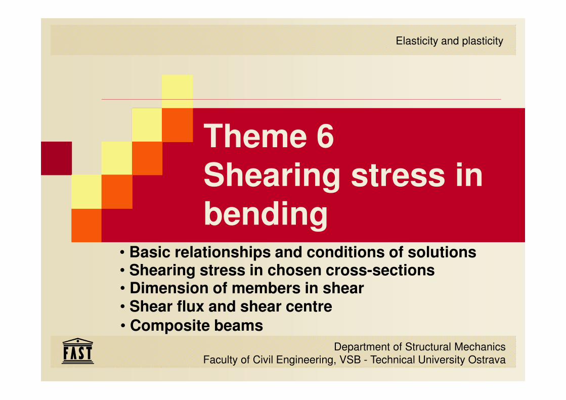
Elasticity and plasticity
Theme 6Shearing stress in bending
• Basic relationships and conditions of solutions• Shearing stress in chosen cross-sections
• Shear flux and shear centre• Dimension of members in shear
• Composite beams
2 / 74
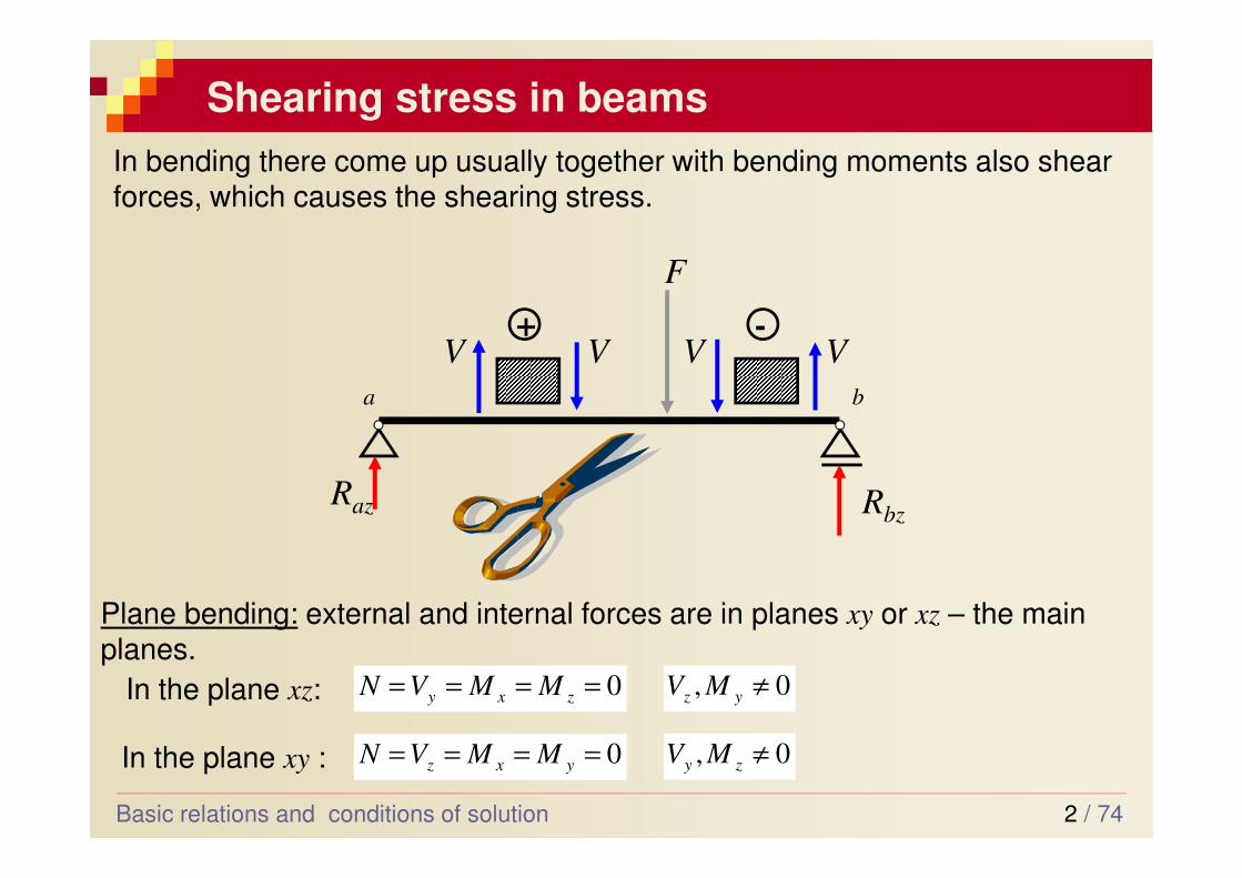
Shearing stress in beams
Basic relations and conditions of solution
ba
+
VV
RbzRaz
F
-
VV
In bending there come up usually together with bending moments also shear forces, which causes the shearing stress.
0, ≠yz MV0==== zxy MMVNIn the plane xz:
Plane bending: external and internal forces are in planes xy or xz – the main
planes.
0, ≠zy MV0==== yxz MMVNIn the plane xy :
3 / 74
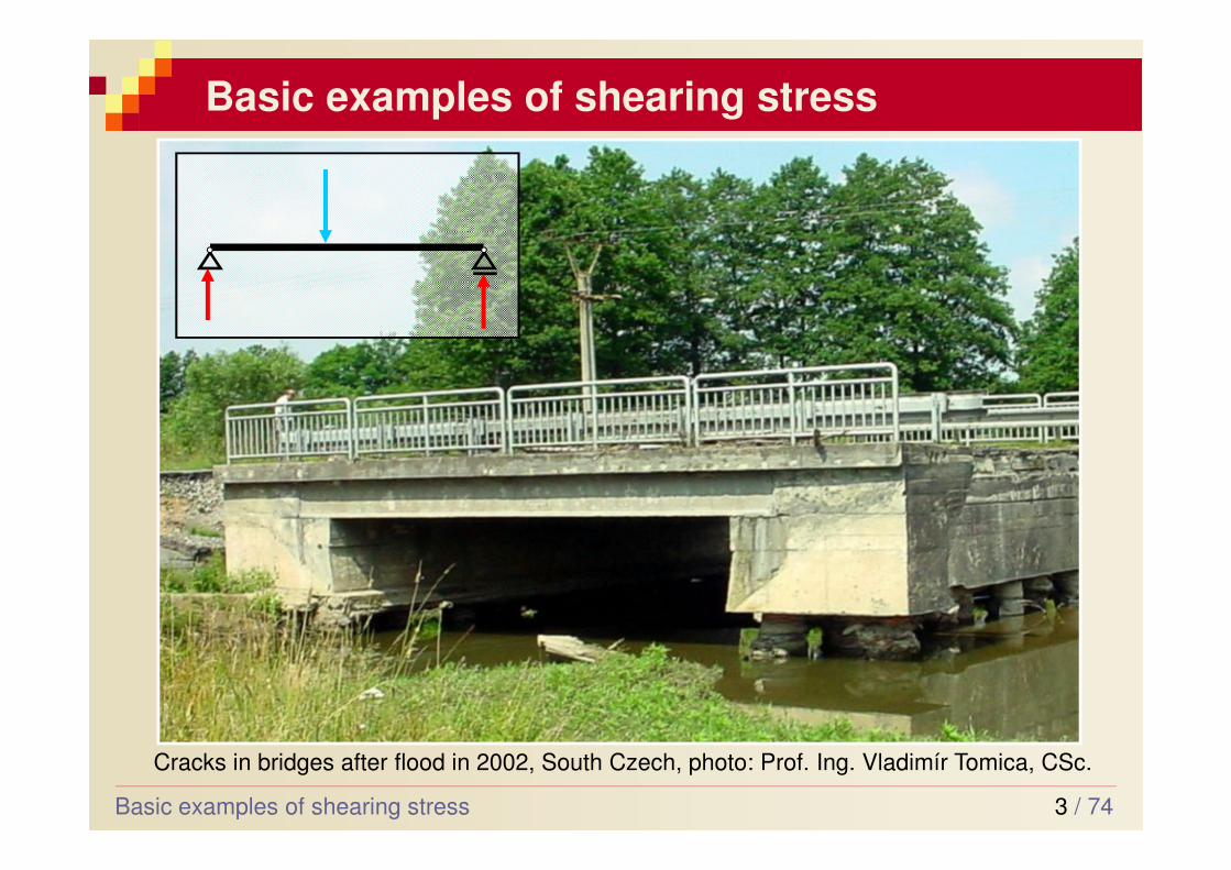
Basic examples of shearing stress
Basic examples of shearing stress
Cracks in bridges after flood in 2002, South Czech, photo: Prof. Ing. Vladimír Tomica, CSc.
4 / 74
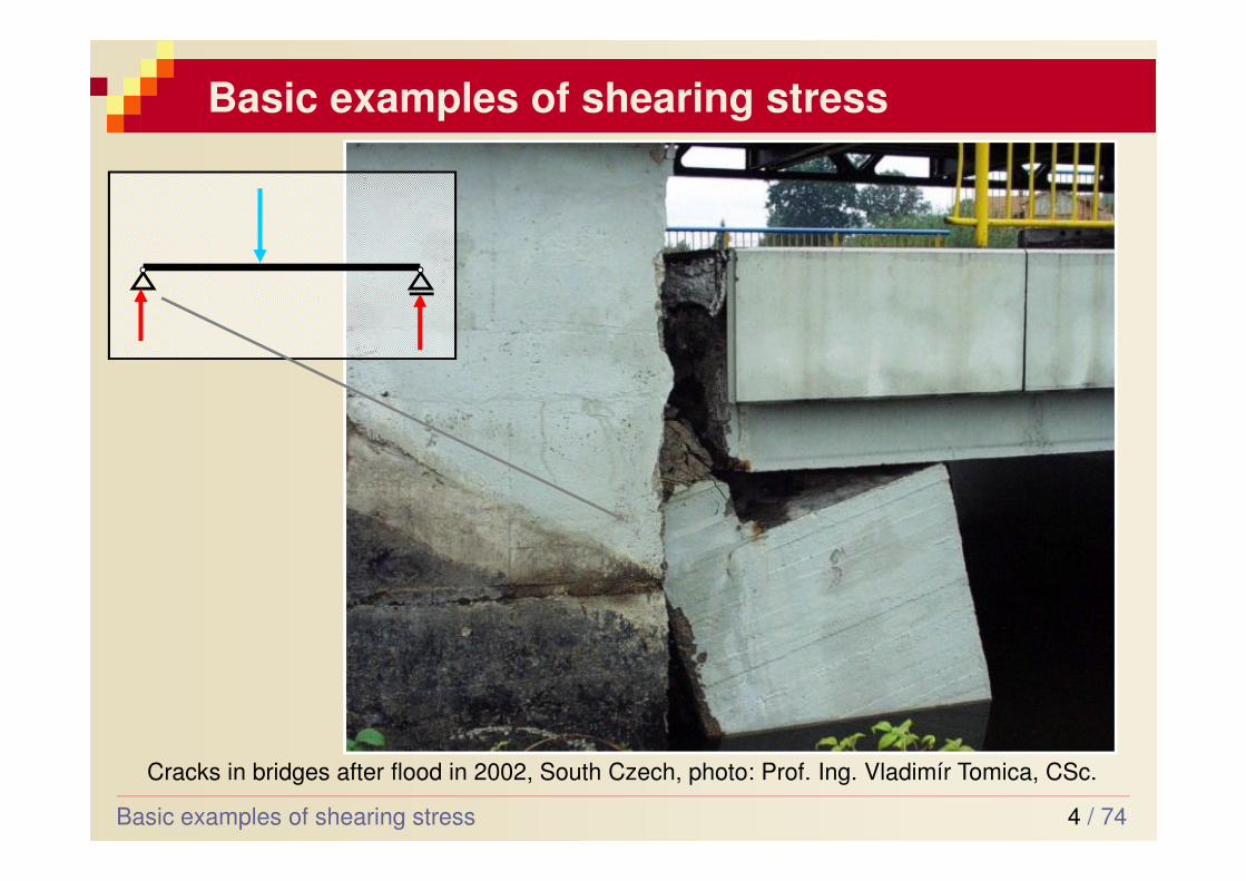
Basic examples of shearing stress
Cracks in bridges after flood in 2002, South Czech, photo: Prof. Ing. Vladimír Tomica, CSc.
Basic examples of shearing stress
5 / 74
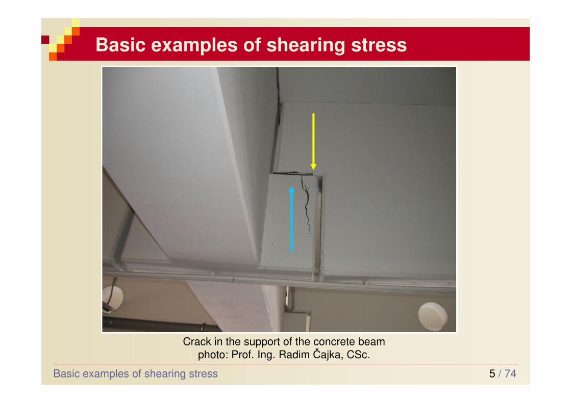
Basic examples of shearing stress
Crack in the support of the concrete beam
photo: Prof. Ing. Radim Čajka, CSc.
Basic examples of shearing stress
6 / 74
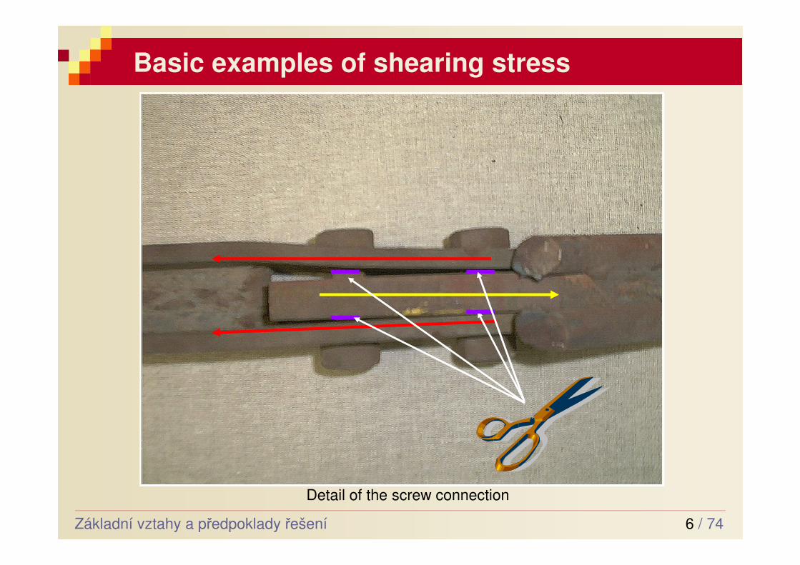
Basic examples of shearing stress
Základní vztahy a předpoklady řešení
Detail of the screw connection
7 / 74
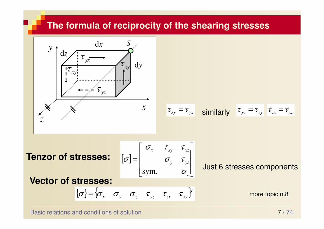
The formula of reciprocity of the shearing stresses
y
z
x
[ ]
=
z
yzy
xzxyx
σ
τσ
ττσ
σ
sym.
Tenzor of stresses:
{ } { }T
xyzxyzzyx τττσσσσ =
Vector of stresses:
more topic n.8
Just 6 stresses components
S
zd
yd
xd
xyτyxτ
yxτ
xyτ
yxxy ττ = zyyz ττ = xzzx ττ =similarly
Basic relations and conditions of solution
8 / 74
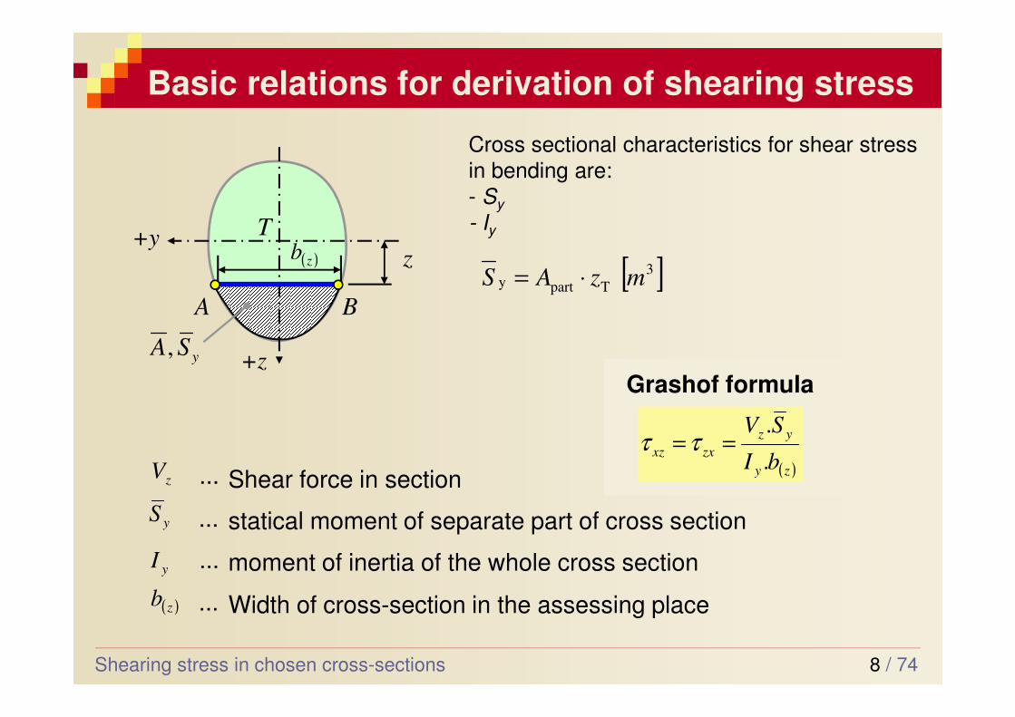
Basic relations for derivation of shearing stress
Shearing stress in chosen cross-sections
+y
+z
A B
T
z( )zb
ySA,
( )zy
yz
zxxzbI
SV
.
.==ττ
statical moment of separate part of cross section...yS
zV ... Shear force in section
yI ... moment of inertia of the whole cross section
( )zb ... Width of cross-section in the assessing place
Grashof formula
Cross sectional characteristics for shear stress
in bending are:
- Sy
- Iy
[ ]3
Tparty mzAS ⋅=
9 / 74
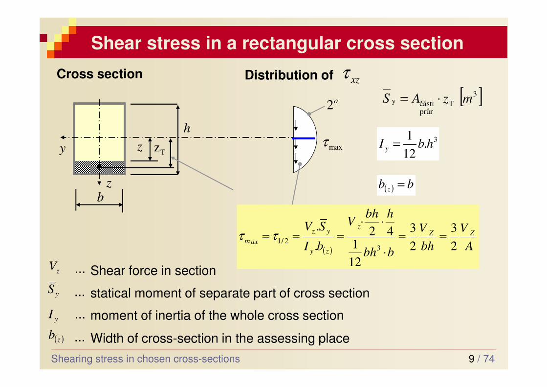
Shear stress in a rectangular cross section
Shearing stress in chosen cross-sections
z
y
b
h
Cross section
maxτ
o2
Distribution of xzτ
z3.
12
1hbI y =
( ) bb z =
Tz
( ) A
V
bh
V
bbh
hbhV
bI
SVZZ
z
zy
yz
axm2
3
2
3
12
142
.
.
32/1 ==
⋅
⋅⋅===ττ
[ ]3
Tprůrčástiy mzAS ⋅=
statical moment of separate part of cross section...yS
zV ... Shear force in section
yI ... moment of inertia of the whole cross section
( )zb ... Width of cross-section in the assessing place
10 / 74
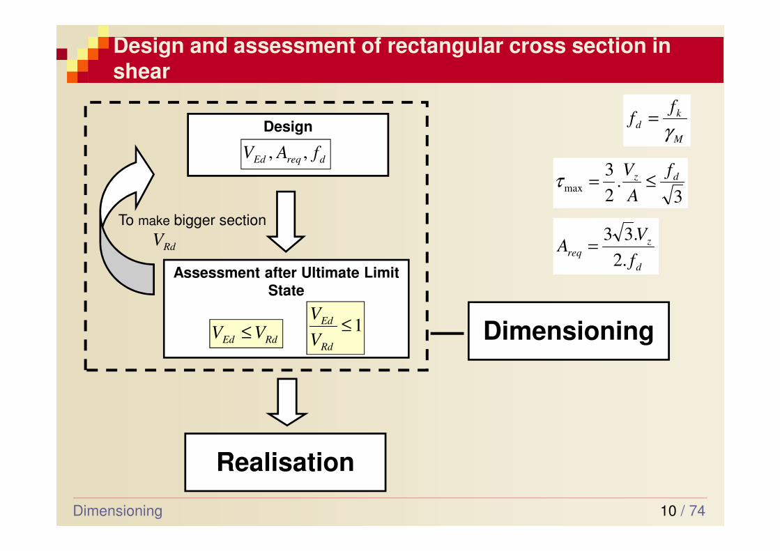
Design and assessment of rectangular cross section in shear
Dimensioning
Assessment after Ultimate Limit
State
Design
Realisation
Dimensioning
dreqEd fAV ,,
RdEd VV ≤
RdVTo make bigger section
M
kd
ff
γ=
3.
2
3max
dz f
A
V≤=τ
d
zreq
f
VA
.2
.33=
1≤Rd
Ed
V
V
11 / 74
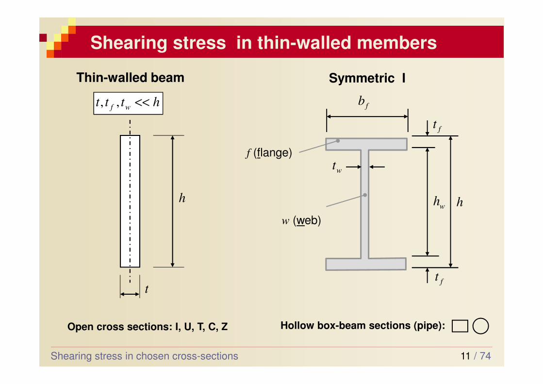
Shearing stress in thin-walled members
Shearing stress in chosen cross-sections
httt wf <<,,
t
h
Symmetric I
hwh
ft
ft
fb
wt
w (web)
f (flange)
Thin-walled beam
Open cross sections: I, U, T, C, Z Hollow box-beam sections (pipe):
12 / 74
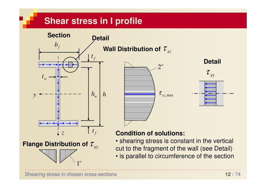
Shear stress in I profile
Shearing stress in chosen cross-sections
Section
Wall Distribution of
z
y
Flange Distribution of
xzτ
xyτ
max,xzτ
o2
hwh
ft
ft
fb
wt
o1
Condition of solutions:• shearing stress is constant in the vertical cut to the fragment of the wall (see Detail)• is parallel to circumference of the section
xyτDetail
Detail
13 / 74
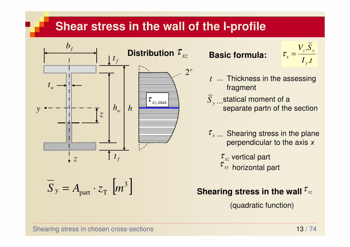
Shear stress in the wall of the I-profile
Shearing stress in chosen cross-sections
Distribution
z
y
xzτ
max,xzτ
o2
hwh
ft
ft
fb
wt
z
tI
SV
y
yz
x.
.=τBasic formula:
t ... Thickness in the assessing
fragment
yS ...statical moment of a
separate partn of the section
xτ ... Shearing stress in the plane perpendicular to the axis x
xzτxyτ
vertical part
horizontal part
Shearing stress in the wall xzτ
(quadratic function)
[ ]3
Tparty mzAS ⋅=
14 / 74
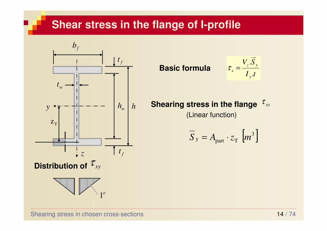
Shear stress in the flange of I-profile
Shearing stress in chosen cross-sections
z
y hwh
ft
ft
fb
wt
Distribution of xyτ
o1
tI
SV
y
yz
x.
.=τBasic formula
Shearing stress in the flange xyτ
(Linear function)
[ ]3
Tparty mzAS ⋅=
Tz
15 / 74
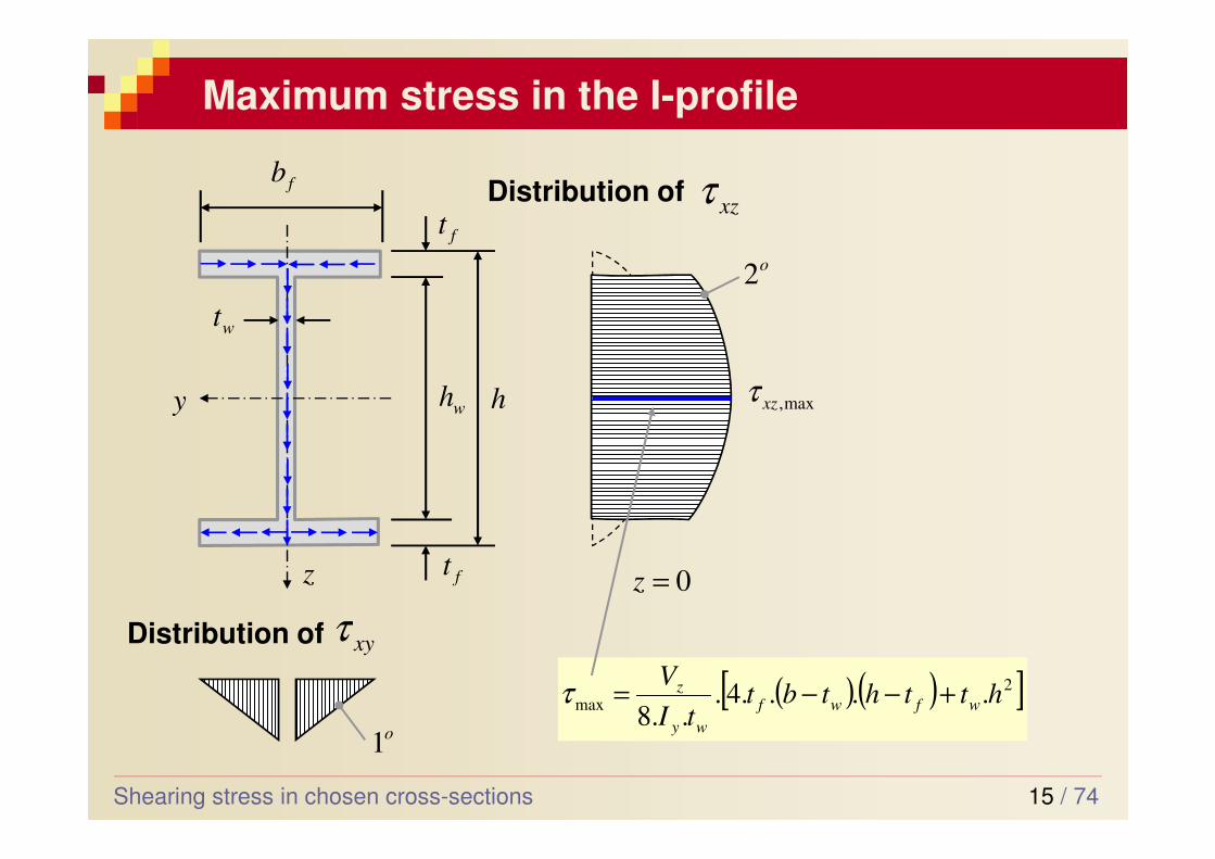
Maximum stress in the I-profile
Shearing stress in chosen cross-sections
Distribution of
z
y
Distribution of
xzτ
xyτ
max,xzτ
o2
hwh
ft
ft
fb
wt
o1
( )( )[ ]2
max ....4...8
htthtbttI
Vwfwf
wy
z +−−=τ
0=z
16 / 74
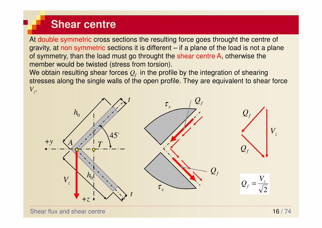
Shear centre
Shear flux and shear centre
At double symmetric cross sections the resulting force goes throught the centre of
gravity, at non symmetric sections it is different – if a plane of the load is not a plane
of symmetry, than the load must go throught the shear centre A, otherwise the
member would be twisted (stress from torsion).We obtain resulting shear forces Qf in the profile by the integration of shearing
stresses along the single walls of the open profile. They are equivalent to shear force Vz.
+y
+z
TA
0h
0h
t
t
zV
o45
fQ
fQ
xτ
xτ
zV
fQ
fQ
2
zf
VQ =
17 / 74
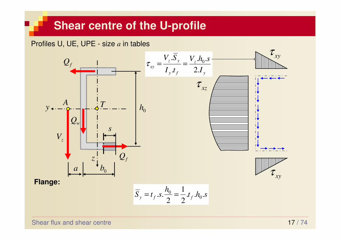
Shear centre of the U-profile
Shear flux and shear centre
z
y T0h
A
zV
fQ
fQ
0ba
wQ
xyτ
xyτ
xzτ
shth
stS ffy ...2
1
2.. 0
0 ==
s
y
z
fy
yz
xyI
shV
tI
SV
.2
..
.
.0==τ
Flange:
Profiles U, UE, UPE - size a in tables
18 / 74
Shear centre of U-profile
Shear flux and shear centre
z
y T0h
A
zV
fQ
fQ
0ba
wQ
xyτ
xyτ
xzτ
s
M
( )[ ]22
000 4....4...8
zhthbttI
Vwf
wy
zxz −+=τ
Web
... likewise I profile
zw VQ =
0.. hQaV fz =Statical moments to point M → y
f
z
f
I
hbt
V
hQa
.4
... 2
0
2
00 ==
19 / 74
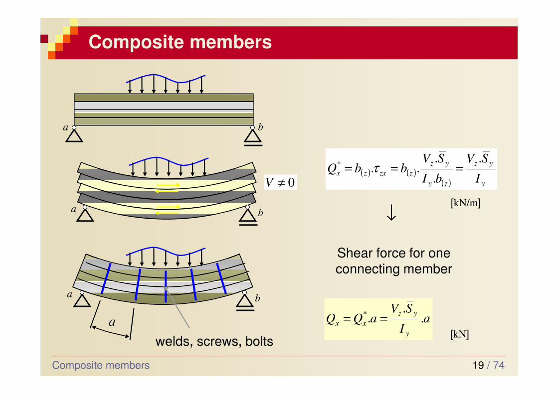
Composite members
Composite members
a b
b
a b
0≠V
welds, screws, bolts
a
a
( ) ( )( ) y
yz
zy
yz
zzxzxI
SV
bI
SVbbQ
.
.
...* === τ
[kN/m]
aI
SVaQQ
y
yz
xx ..
.* ==[kN]
Shear force for one connecting member
↓
20 / 74
Questions for the exam
1. Shearing stress in bending of the rectangular cross section
2. Shearing stress in bending of thin-walled members, shear centre
3. Assessment of the members under shear stress in bending
4. Composite members
Questions for the exam