Embed Size (px)
Citation preview

1
SHEAR TRA�SFER ALO�G I�TERFACES: CO�STITUTIVE LAWS
Vasiliki PALIERAKI1, Elizabeth VINTZILEOU
2 and Konstantinos TREZOS
3
ABSTRACT
This paper presents constitutive laws adequate for predicting the maximum shear load that can be
transferred along reinforced concrete interfaces subjected to monotonically or cyclically imposed
displacements. A previous empirical formula is modified with the purpose to reach reliable prediction
of the maximum resistance of various types of reinforced concrete interfaces. The application of the
modified formula to 580 experimental results from the literature proves the adequacy of the proposed
laws.
I�TRODUCTIO�
In various repair and/or strengthening techniques, in case that the intervention consists in adding a new
concrete layer or new RC elements to the existing members of the structure, the connection between
the new and the old concrete has to be adequately designed and detailed. Various techniques suggested
and used in construction, aim to establish a better connection between the two different layers, so that
the resulting, composite, element behaves as monolithic. Nevertheless, the shear load to be transferred
along the interfaces, depends on the means of connecting the old and the added concrete (use of
reinforcing bars or anchors, acting as dowels, roughening of the old concrete surface before casting the
new layer) and it is a function of the shear slip along interfaces, a prerequisite for the mobilization of
the resistance at the interface. In case of structures subjected to earthquakes, the behaviour of
interfaces may become critical for the overall behaviour of the structure, due to substantial degradation
of the resistance of the interface under cyclic actions.
On the other hand, in the design of an interface crossed by reinforcing bars or by anchors, one
cannot additively superimpose the maximum resistance offered by the two main mechanisms (shear
friction and dowel action). The interaction between the two mechanisms has to be taken into account,
along with the fact that their maximum resistance is not mobilized for the same value of shear slip.
Although, the behaviour of interfaces was experimentally investigated in numerous studies, the
available information is not sufficient for the design of interfaces in the case of RC structures
subjected to earthquake excitations. An experimental campaign was carried out at the Laboratory of
RC, NTUA, for the systematic investigation of RC interfaces within repaired or strengthened
elements. Among the aims of the experimental investigation is also the proposal of constitutive laws
for the accurate prevision of the interface resistance and overall behavior.
In the present paper a summary of the available experimental results is presented, as well as the
results of a study that was undertaken with the aim to predict the maximum resistance of RC interfaces
under imposed monotonic or cyclic excitation.
1 Dr., Civil Engineer, National Technical University of Athens, Athens, Greece, [email protected]
2 Professor, Civil Engineer, National Technical University of Athens, Athens, Greece, [email protected]
3 Assistant Professor, Civil Engineer, National Technical University of Athens, Greece, [email protected]

2
LITERATURE SURVEY
The results of numerous tests on (plain or reinforced) concrete interfaces are reported in the
international literature. Tests simulate various cases of interfaces, such as construction joints,
connections between precast elements, natural cracks, etc. In most of the tests, interfaces were
subjected to monotonically increasing load up to failure. Data regarding the behaviour of reinforced
interfaces simulating the interfaces between old and new concrete in repaired/strengthened elements,
subjected to cyclic shear slip are rather scarce. The experimental research carried out by the authors,
mainly aims at covering the lack of results regarding the cyclic behavior of interfaces between old and
new concrete, in repaired or strengthened elements.
The number of tests performed at NTUA (43 tests on specimens subjected to cyclic shear slip,
Palieraki, 2014) allow for conclusions regarding the behavior of interfaces in cyclic shear to be drawn.
Nevertheless, it is obvious that the tests do not cover the wide range of the parameters influencing the
behavior of the interfaces, e.g., the mechanical characteristics of concrete and steel. In order to
formulate a constitutive law, which could be generally applied, experimental results from the literature
are re-evaluated.
Tests regarding the behavior of interfaces are performed using (a) specimens in the form of
beams, strengthened using added concrete, tested in 3-point bending, causing indirect shear of the
interface, (b) monolithic specimens, tested as constructed, or cracked before being tested,
(c) specimens constructed in two consecutive phases, simulating interfaces between new and old
concrete, as are the specimens tested by the authors, and finally (d) specimens having two interfaces,
simulating connections between precast concrete elements. In some of the specimens, compressive or
tensile stress is applied perpendicularly to the interface. The percentage of the reinforcement crossing
the interface varies between 0.014% and 4%, while the most frequently used percentages are in the
range of 0.5% to 2%.
The different test setups used in order to perform the tests have some common characteristics,
but may present significant differences, depending on how the interface is constructed (in one or two
phases) and according to the purpose of the investigation. One of the most commonly used test setups
is similar to the one used at NTUA (Fig.1).
Given that different kinds of test setups can be found in the literature, leading to different
results, not directly comparable in several cases, and given the particular interest of interfaces between
old and new concrete, attention has been paid to the aforementioned cases of interfaces. In total,
results from 18 papers, produced between 1960 and 2012 have been collected. Results from almost
580 tests regarding interfaces with different dimensions and geometry, covering a wide range of
material properties are included in the evaluated research works.
(a) (b)
Figure 1. Tests at NTUA: (a) Geometry of the specimens with three bars crossing the interface (dimensions in
meters), (b) Photo of the test set up, with specimen in the testing position.
C
C
A
S
F F
R
Section A-A
Section B-B
Bars of 8mm
or 12mm
diameter

V.Palieraki, E.Vintzileou and K. Trezos 3
MAXIMUM I�TERFACE RESISTA�CE-I�FLUE�CE OF SIG�IFICA�T
PARAMETERES
The available experimental results reported in the literature have been re-evaluated and assessed in
relation to significant parameters, which, as generally admitted, affect the behavior of interfaces. Shear
is transferred along the interfaces mobilizing the mechanism of concrete to concrete friction and the
dowel action of the bars crossing the interface. The main parameters under investigation are the
compressive strength of concrete, the number and the diameter of the bars crossing the interface, the
anchorage length of the bars crossing the interface, and the presence of compressive or tensile stress,
acting perpendicularly to the interface. Given that in the present paper the resistance of interfaces
between old and new concrete is investigated, the specimens usually consist of two parts, constructed
separately. The smaller compressive strength of the concrete of the two parts of the specimens is the
one that governs the resistance of the interface. The parameters related to the percentage of the
reinforcement crossing the interface, can be unified in one parameter, ρfy (where “ρ” denotes the
percentage of reinforcement and “fy” denotes the yield strength of the bars), which corresponds to the
maximum compressive stress which can act on the concrete interface, because of the tensile stresses to
be developed in the reinforcing bars of the interface. In the parameter, the small anchorage length of
the bars can be taken into account, given that for smaller length the tensile stress in the bars is
considered to be reduced. Additionally, in the parameter ρfy, the external compressive or tensile stress,
acting to the interface is added or subtracted accordingly.
As long as it regards the embedment length, it is taken into account as follows: Most of the
specimens are reinforced with bars in the form of closed loops. The bars in this case, are considered to
be sufficiently anchored, and able to develop their yield strength. The bars anchored by means of
resins are also considered to be able to develop their yielding stress. In the case of bars anchored to the
concrete by means of bond, having a small embedment length, the stress to be developed in the bars is
considered to be smaller than their yielding stress. The tensile stress in the bars, and consequently the
compressive stress to be developed in the concrete can be calculated according to Eq. (1):
bc
syemb
cl80.0A
Afl=σ (N, mm) (1)
In Eq. (1), the embedment length that is necessary for the bars to develop their yield strength is
taken equal to 80% that prescribed by EC2 (Eq. (2)). This is because, the experimental results obtained
at NTUA (Vintzileou and Palieraki, 2007, Palieraki and Vintzileou, 2009, Zeris et al., 2011, Palieraki,
2014) have shown that embedment length equal to 0.80lb is sufficient for the full anchorage of bars
used for the reinforcement of interfaces subjected to shear.
bu
yd
bf4
fl
Φ= (N, mm) (2)
The effect of the main parameters on the maximum resistance of interfaces is shown in Fig. 2:
The resistance of the interface is plotted against the least of the two compressive strengths, as well as
against the values of the parameter “ρfy”. In addition, to make the effect of the compressive strength
of concrete more evident, the shear resistance values are reported to the parameter “ρfy”.
The diagrams for the specimens simulating interfaces between old and new concrete clearly
show that the reinforcement parameter is the one governing the resistance along the interface. The
increase of the reinforcement percentage leads to an increase of the interface resistance. The influence
of the concrete compressive strength is not so clear. For normal concrete compressive strength, up to
60.00MPa, the increase of the concrete strength leads to an increase of the interface resistance. This
trend is not clear for higher values of the compressive strength of concrete. In case of interfaces
formed within a monolithic element, cracked before testing the interface, this feature can be attributed
to the fact that a crack in high strength concrete crosses not only the cement matrix, but also the
aggregates, leading to a smoother interface. In the case of interfaces between old and new concrete,
this could be also attributed to the different roughness of the interface.

4
0 12020 40 60 80 100
fc (N/mm2)
0
5
10
15
20
τu,exp (N/mm2 )
Hanson, 1960
Mattock, 1976
Vesa, 1978
Noguchi et al., 1984
Bass et al., 1989
Mishima et al., 1995
Randl, 1997
Choi et al., 1999
Choi et al., 1999 (2)
Valluvan et al., 1999
Kono et al., 2001
Kann & Mitchell, 2002
Papanicolaou & Triantafillou, 2002
Nakano & Matsuzaki, 2004
Saari et al., 2004
Hattori & Yamamoto, 2007
Harries et al., 2012
NTUA Tests, 2007-2013
0 204 8 12 16ρfy (N/mm
2)
0
5
10
15
20
τu,exp (N/mm2 )
0 12020 40 60 80 100
fc (N/mm2)
0
2
4
6
8
10
12 τu,exp/ρf y
Figure 2. The effect of the least concrete compressive strength and the reinforcement parameter, ρfy, on the shear
resistance of interfaces between old and new concrete.
PREDICTIO� OF THE MAXIMUM I�TERFACE RESISTA�CE-AVAILABLE
RELATIO�SHIPS
In the literature, as well as in some Codes, several relationships are given for the prediction of the
maximum interface resistance. Those relationships cannot always be applied in the case of interfaces
between old and new concrete, in repaired/strengthened elements, because of the specific
characteristics of the abovementioned interfaces: The quality and the strength of the new and the old
concrete may differ significantly. The surface of the old concrete may be smooth or roughened, using
various techniques. The interface reinforcement is anchored in the old concrete by means of resins or
other mechanical means, while in the new concrete, the anchorage of the reinforcement is achieved
through bond with the concrete. The dimensions of the old, as well as the added part of concrete, are
often small, not allowing for full anchorage of the reinforcement or/and for sufficient distances from
the edges of the elements.
Among all the available relationships, those able to predict the shear resistance of interfaces
between old and new concrete are used on a large number of experimental data from various sources.

V.Palieraki, E.Vintzileou and K. Trezos 5
Those relationships were proposed by researchers (Pruijssers, 1988, Tassios and Vassilopoulou, 2003,
Harries et al., 2012), or they are included in Codes (ACI 318, 2011 and CEB-fib Model Code 10,
2012).
Equation proposed by Pruijssers (1988), Equ. (3): b
yu )f(a ρτ = (3)
Where: ρ denotes the reinforcement percentage of the interface
fy denotes the yield strength of the steel
α and b are empirical parameters: 406.0
ccmf822.0a = and 303.0
ccmf159.0b =
fccm denotes the compressive strength of conventional 150mm cubes.
It is noted that the relationship is proposed by Pruijssers (1988) for interfaces within specimens
constructed monolithically and cracked before testing.
Equation proposed by Tassios and Vassilopoulou (2003), Equ. (4):
ffddu τβτβτ += (4)
Where βd and βf are contribution factors for the mechanisms acting along the interface, namely
friction (Equ. (5), as proposed by Tassios and Vintzileou, 1987) and dowel action (Equ. (6), as
proposed by Rasmussen, 1962). The formula by Rasmussen is valid for dowels provided with concrete
cover sufficient for splitting failures to be avoided as described herein:
3c
2
cf f44.0 στ = (N, mm) (5)
where: fc denotes the least compressive strength of concrete
σc denotes the compressive stress acting perpendicularly to the interface. The compressive stress
may be due to an external acting stress or to the tensile stress of the bars crossing the interface (=ρfs, fs
denotes the tensile stress of the bars),
cyc
2
bd A/)ffnd30.1(=τ (N, mm) (6)
where: n and db denote the number and the diameter of the bars crossing the interface.
The contribution factors for the mechanisms acting across the interface (βd and βf), were
determined by Tassios and Vassilopoulou (2003) on the basis of experimental results obtained from
testing each shear transfer mechanism separately (Vintzeleou and Tassios, 1987, Tassios and
Vintzileou, 1987) and taking into account the interaction between the two mechanisms. Tassios and
Vassilopoulou (2003), have concluded that for slip values not exceeding 0.40mm, the contribution
factor of the friction mechanism is equal to 0.40, whereas that of the dowel mechanism is equal to
0.70. For large values of the imposed shear slip (s>2.00mm), the contribution factor of the friction
mechanism becomes equal to 0.80, that of the dowel action remaining equal to 0.70. When the value
of the imposed slip is not known, or for concrete strength higher than 40.00MPa, Tassios and
Vassilopoulou (2003) suggest to use reduced contribution factors, namely 0.70 and 0.60 for friction
and dowel action respectively. Given that the values of the imposed shear slip are not known for all
the available experimental results, and the concrete strength is for many tests higher than 40.00MPa,
for the comparison in the current paper, the contribution factors of 0.70 and 0.60 for friction and dowel
action respectively are used.
Equation proposed by Harries et al. (2012), Equ. (7):
cscu f20.0E002.0af ≤+= ρτ (N, mm) (7)
where: Es denotes the elastic modulus of the interface steel reinforcement
α stands for an empirical parameter. The value of the parameter is taken into account according
to the type of the specimen under investigation, i.e.:
α= 0.075 for monolithic, uncracked, specimens
α= 0.040 for specimens having a cold joint, constructed in two different phases (the case of
interfaces between old and new concrete)
α= 0.000 for specimens cracked before testing
Equ. (7) is a design-oriented equation. Given that the equation is used to predict experimental
results, partial safety factors for the materials, namely for concrete and steel, are not used. It has to be
6
admitted though that avoiding the use of safety factors may not be sufficient for a design-oriented
equation. Thus, it is expected to lead to resistance values smaller than the experimental ones.It is noted
that in Equ. (7), the elastic modulus of the steel crossing the interface is used, instead of its yield
strength: According to the tests performed by Harries et al. (2012), and the steel strains measured
during testing, Harries et al. (2012) suggest that, in case of high or medium strength steel
(fy>400MPa), the bars do not reach their yield strength.
Equations proposed in Codes:
ACI 318 (2011), equation (Equ. (8)):
)515.5,f20.0min(A/f ccysu ≤Α= µτ (N, mm) (8)
where: µ denotes the friction coefficient along the interface; a set of values are specified for
different interface construction methods, namely,
µ=1.40 for monolithic, cracked or uncracked, specimens
µ=1.00 and µ=0.60 for concrete placed against hardened concrete, for rough or smooth interface
of the hardened concrete, respectively.
Equ. (8) is one of the most commonly used equations for the calculation of the interface
resistance. It is noted that many researchers, including the authors of this paper, have concluded that
the upper limits, suggested by the ACI Code, i.e. the limit of 0.20fc or 5.515MPa are extremely
conservative. Based on this observation, the limit of 5.515MPa is not taken into account in the
following calculations, while instead of 0.20fc, the less conservative, but still on the safe side, limit of
0.25fc is used. It is noted, that also in this case, the partial safety factors for the materials are not taken
into account.
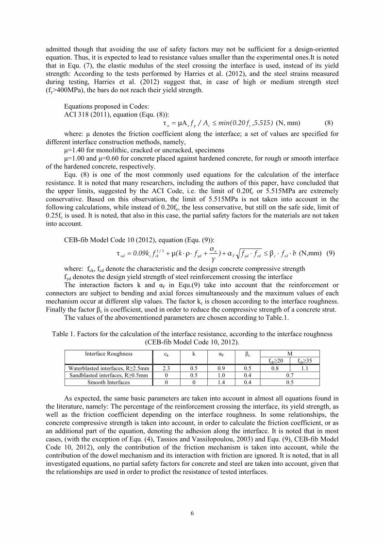
CEB-fib Model Code 10 (2012), equation (Equ. (9)):
bfff)γ
fk(fk09.0 cdccdydFn
dy
3/1
ckcud ⋅⋅≤⋅++⋅⋅+= βασ
ρµτ (N,mm) (9)
where: fck, fcd denote the characteristic and the design concrete compressive strength
fyd denotes the design yield strength of steel reinforcement crossing the interface
The interaction factors k and αF in Equ.(9) take into account that the reinforcement or
connectors are subject to bending and axial forces simultaneously and the maximum values of each
mechanism occur at different slip values. The factor kc is chosen according to the interface roughness.
Finally the factor βc is coefficient, used in order to reduce the compressive strength of a concrete strut.
The values of the abovementioned parameters are chosen according to Table.1.
Table 1. Factors for the calculation of the interface resistance, according to the interface roughness
(CEB-fib Model Code 10, 2012).
Μ Interface Roughness ck k αF βc
fck≥20 fck≥35
Waterblasted interfaces, R≥2.5mm 2.3 0.5 0.9 0.5 0.8 1.1
Sandblasted interfaces, R≥0.5mm 0 0.5 1.0 0.4 0.7
Smooth Interfaces 0 0 1.4 0.4 0.5
As expected, the same basic parameters are taken into account in almost all equations found in
the literature, namely: The percentage of the reinforcement crossing the interface, its yield strength, as
well as the friction coefficient depending on the interface roughness. In some relationships, the
concrete compressive strength is taken into account, in order to calculate the friction coefficient, or as
an additional part of the equation, denoting the adhesion along the interface. It is noted that in most
cases, (with the exception of Equ. (4), Tassios and Vassilopoulou, 2003) and Equ. (9), CEB-fib Model
Code 10, 2012), only the contribution of the friction mechanism is taken into account, while the
contribution of the dowel mechanism and its interaction with friction are ignored. It is noted, that in all
investigated equations, no partial safety factors for concrete and steel are taken into account, given that
the relationships are used in order to predict the resistance of tested interfaces.
V.Palieraki, E.Vintzileou and K. Trezos 7
Hanson, 1960
Mattock, 1976
Vesa, 1978
Noguchi et al., 1984
Bass et al., 1989
Mishima et al., 1995
Randl, 1997
Choi et al., 1999
Choi et al., 1999 (2)
Valluvan et al., 1999
Kono et al., 2001
Kann & Mitchell, 2002
Papanicolaou & Triantafillou, 2002
Nakano & Matsuzaki, 2004
Saari et al., 2004
Hattori & Yamamoto, 2007
Harries et al., 2012
NTUA Tests, 2007-2013
0 205 10 15
τu,calc, pruijssers (N/mm2)
0
5
10
15
20
τu,exp (N/mm2 )
0 205 10 15
τu,calc, tassios (N/mm2)
0
5
10
15
20
τu,exp (N/mm2 )
0 205 10 15
τu,calc,harries (N/mm2)
0
5
10
15
20 τu,exp (N/mm2 )
0 205 10 15
τu,calc,ACI (N/mm2)
0
5
10
15
20
τu,exp (N/mm2 )
0 205 10 15
τu,calc,fib (N/mm2)
0
5
10
15
20
τu,exp (N/mm2 )
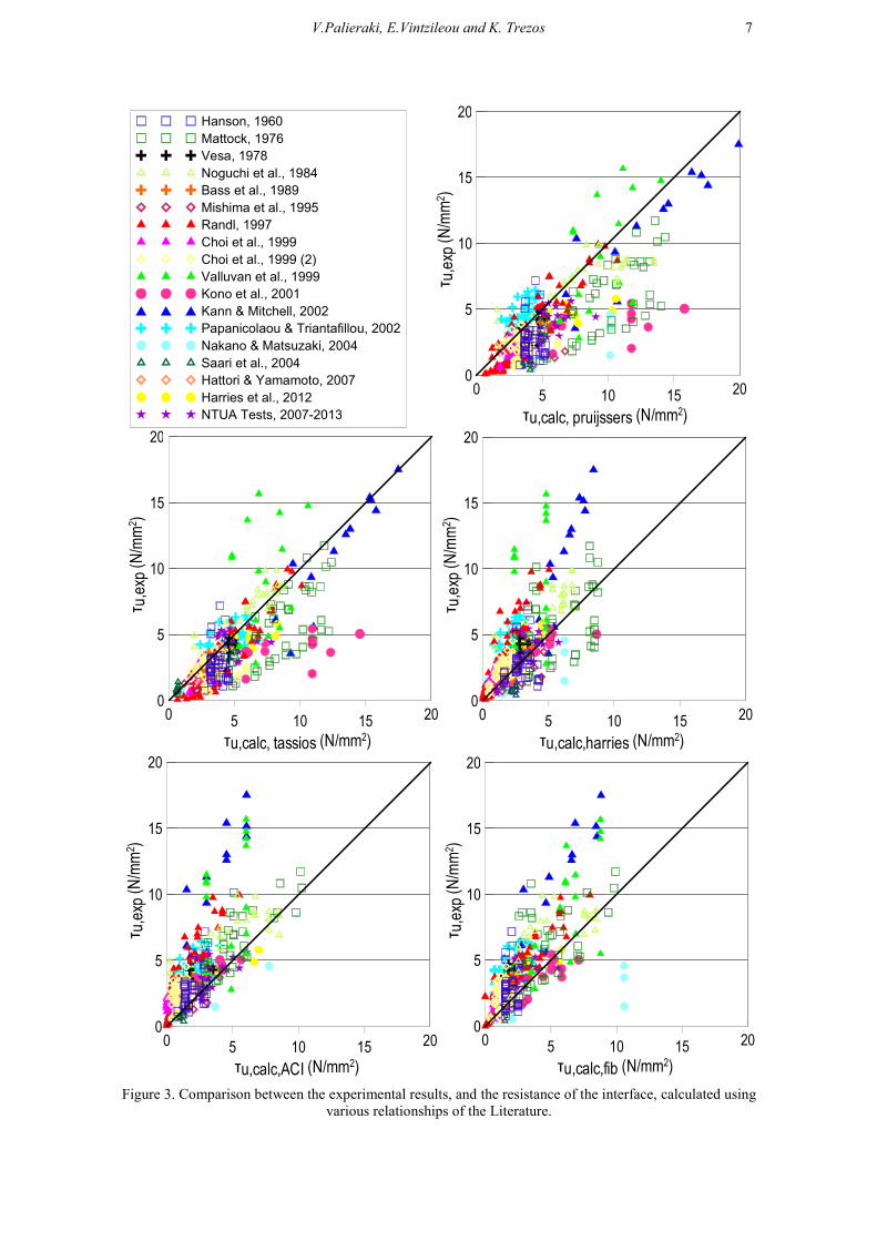
Figure 3. Comparison between the experimental results, and the resistance of the interface, calculated using
various relationships of the Literature.
8
In Fig. 3, the values of the shear resistance of interfaces, calculated on the basis of the
aforementioned equations are plotted against the respective experimental values. One may observe the
significant scatter of the results of this comparison. Regarding each separate equation, one may
comment as follows: The predictions according to Equ. (3) and to Equ. (4) (Pruijssers, 1988, Tassios
and Vassilopoulou, 2003) are not on the safe side, as they yield systematically interface resistance
values higher than the experimental ones. This is attributed to the fact that both equations were
proposed for natural cracks and, hence, they do not yield accurate results in case of interfaces of
limited roughness. On the contrary, Equ. (8), included in the ACI Code, applied as described
previously (taking into account less conservative upper limits) leads to satisfactory results. Although
Equ. (8) neglects the contribution of dowel action, the fictitiously higher friction coefficients proposed
by the Code contribute to the calculation of realistic values for the overall shear resistance, Finally,
Equ. (9) included in the CEB-fib Model Code 10 (2012), shows significant scatter. It should be noted
that the values of shear resistance being calculated-for the needs of this comparison-without
accounting for partial safety factors seem to be much on the unsafe side.
FORMULATIO� OF A MODIFIED RELATIO�SHIP
Among the numerous relationships available in the Literature, that proposed by Tassios and
Vassilopoulou (2003), is selected for further investigation. This choice is justified by the purpose of
the present work: The design of interfaces in repaired or strengthened RC elements is carried out,
according to current Codes (e.g. EC8, Part 3), for a given performance level. The shear slip expected
to be imposed to the interface is a function of the design performance level. It is, therefore, necessary
to provide the Designer with a formula able to take into account the contribution of each separate
mechanism (a function of the imposed slip value), as well as the roughness of the interface, the
presence of external normal stress, etc. The selected formula offers this possibility.
Thus, taking into account the available experimental data, the authors of this paper are
proposing a set of modified factors to be implemented in Equ. (4):
Dowel action: The contribution of the mechanism to the overall resistance of the interface is
taken equal to 70% the maximum resistance due to dowel action (i.e., βd=0.70). For bars having an
embedment length smaller or equal to 6 times the diameter of the bars (the length is compared to a
length equal to 8 times the diameter of the bar, which is a length necessary for the full capacity of the
dowel to be mobilized), the contribution of the dowel mechanism is reduced by a factor equal to 0.75.
It is to be noted that the contribution of the dowel mechanism in the overall shear resistance of the
interface is in general rather limited. It is expected to affect the overall resistance only for small
imposed shear slip values, when the contribution of friction is also small.
Friction along the interface: The most significant modifications to the relationship proposed by
Tassios and Vassilopoulou (2003) are brought to the part of the friction mechanism. The comparison
between the experimental results and the values predicted by Equ. (4) show that the contribution of the
friction mechanism cannot be accurately estimated, unless significant parameters, like roughness of
the interface, presence of external normal stress, as well as type of loading (monotonic, cyclic or
repeated) are taken into account.
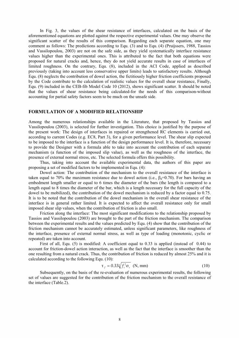
First of all, Equ. (5) is modified: A coefficient equal to 0.33 is applied (instead of 0.44) to
account for friction-dowel action interaction, as well as the fact that the interface is smoother than the
one resulting from a natural crack. Thus, the contribution of friction is reduced by almost 25% and it is
calculated according to the following Equ. (10):
3c
2
cf f33.0 στ = (N, mm) (10)
Subsequently, on the basis of the re-evaluation of numerous experimental results, the following
set of values are suggested for the contribution of the friction mechanism to the overall resistance of
the interface (Table.2).
V.Palieraki, E.Vintzileou and K. Trezos 9
Table 2. Interfaces between old and new concrete: Contribution factors for the friction mechanism.
Interface Characteristics βf
Rough interface, monotonic loading 0.60
Smooth interface with external compressive stress 0.60
Smooth interface 0.40
Rough interface, cyclic loading, imposed shear slip s>1.00mm 0.40
Very smooth interface 0.20
Rough interface, cyclic loading, imposed shear slip s<0.20mm 0.20
Smooth interface, no cohesion along the interface 0.10
Rough interface with external compressive stress 0.80
Interface with shear keys 0.80
0 205 10 15
τu,calc,current (N/mm2)
0
5
10
15
20
τu,exp (N/mm2 )
0 205 10 15
τu,calc,safety factors (N/mm2)
0
5
10
15
20
τu,exp (N/mm2 )
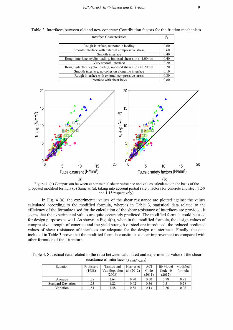
(a) (b) Figure 4. (a) Comparison between experimental shear resistance and values calculated on the basis of the
proposed modified formula (b) Same as (a), taking into account partial safety factors for concrete and steel (1.50
and 1.15 respectively).
In Fig. 4 (a), the experimental values of the shear resistance are plotted against the values
calculated according to the modified formula, whereas in Table 3, statistical data related to the
efficiency of the formulae used for the calculation of the shear resistance of interfaces are provided. It
seems that the experimental values are quite accurately predicted. The modified formula could be used
for design purposes as well. As shown in Fig. 4(b), when in the modified formula, the design values of
compressive strength of concrete and the yield strength of steel are introduced, the reduced predicted
values of shear resistance of interfaces are adequate for the design of interfaces. Finally, the data
included in Table 3 prove that the modified formula constitutes a clear improvement as compared with
other formulae of the Literature.
Table 3. Statistical data related to the ratio between calculated and experimental value of the shear
resistance of interfaces (τu,calc/τu,exp).
Equation
Pruijssers
(1988)
Tassios and
Vassilopoulou
(2003)
Harries et
al. (2012)
ACI
Code
(2011)
fib Model
Code 10
(2012)
Modified
formula
Average 1.78 1.64 0.90 0.60 0.78 0.91
Standard Deviation 1.23 1.22 0.62 0.36 0.51 0.28
Variation 1.51 1.48 0.38 0.13 0.26 0.08

10
CO�CLUSIO�S
The numerous experimental data of the literature regarding the shear resistance of RC interfaces are
evaluated and used to check the efficiency of various relationships in predicting with acceptable
accuracy the measured shear resistance values. Among the formulae used in this paper, the formula
proposed by Tassios and Vassilopoulou (2003) was selected for further investigation, as it accounts for
both shear transfer mechanisms, as well as for their interaction. A set of modified coefficients is
proposed, based on a vast database (including almost 580 test results). The application of the modified
formula has proved its satisfactory performance in predicting the shear resistance of interfaces subject
to monotonic and cyclic shear displacements.
REFERE�CES
ACI Committee 318 (2011) Building Code Requirements for Structural Concrete (ACI 318-11) and
Commentary”, American Concrete Institute, Farmington Hills, Mich. 503 pp.
Bass RA, Carraquillo RL, Jirsa JO (1989) “Shear Transfer across New and Existing Concrete Interfaces”, ACI
Structural Journal, 86(4): 383-393.
Choi D-U, Fowler DW, Jirsa JO (1999) “Interface Shear Strength of Concrete at Early Ages”, ACI Structural
Journal, 96(3): 343-348.
Choi D-U, Jirsa JO, Fowler DW (1999) (2) “Shear Transfer across Interface between New and Existing
Concretes Using Large Powder-Driven Nails”, ACI Structural Journal, 96(2): 183-192.
EC2, Eurocode 2: EN 1992-1 (2009) “Design of concrete structures”, Brussels: European Committee for
Standardization.
EC8, Eurocode 8: EN 1998-1 (2009) “Design of structures for earthquake resistance”, Brussels: European
Committee for Standardization.
Fib (2012) fib Bulletin No. 65: Model Code 2010 - Final draft, Vol. 1, International Federation for Structural
Concrete, Lausanne, Switzerland, 350 pp.
Hanson NW (1960) “Precast-Prestressed Concrete Bridges 2: Horizontal Shear Connections”, Journal of the
PCA Research and Development Laboratories, 2(2): 38-58.
Harries KA, Zeno G, Shahrooz B (2012) “Toward an Improved Understanding of Shear-Friction Behavior”, ACI
Structural Journal, 109(6): 835-844.
Hattori Y and Yamamoto Y (2007) “Shear Transfer Mechanism to bonded Anchors for Exterior Seismic
Retrofitting”, Proceedings of the 2nd International Symposium on Connections between Steel and
Concrete, Stuttgart, Germany, 4-7 September, Vol. 2: 759-769.
Kann LF and Mitchell AD (2002) “Shear Friction Tests with High-Strength Concrete”, ACI Structural Journal,
99(1): 98-103.
Kono S, Tanaka H, Watanabe F (2001) “Interface Shear Transfer for High Strength Concrete and High Strength
Shear Friction Reinforcement”, Proceeding of the Conference on High Performance Materials in
Bridges, ASCE, Kona, Hawaii, 29 July- 3 August, 319-328.
Mattock AH (1976) “Shear Transfer Under Monotonic Loading, Across an Interface Between Concretes Cast at
Different Times”, Report SM 76-3, Department of Civil Engineering, University of Washington (Part I of
Final Report to 5ational Science Foundation, Grant 5o. Eng74-21131).
Mishima T, Suzuki A, Shinoda Y, Maekawa K (1995) “Nonelastic Behavior of Axial Reinforcement Subjected
to Axial and Slip Deformation at the Crack Surface”, ACI Structural Journal, 92(3): 380-385.
Nakano K and Matsuzaki Y (2004) “Design Method and Compound Effect considering deformation of shear
transfer elements in precast concrete connections”, Proceedings of the 13th World Conference on
Earthquake Engineering, Vancouver, Canada, 1-6 August, Paper No. 631.
Noguchi H, Ochiai M, Izhuka S (1984) “Sliding Shear in Cracked Reinforced Concrete Shear Walls Subjected to
Reversed Cyclic Shear”, Proceedings of the 8th World Conference on Earthquake Engineering, San
Francisco, California, 21-28 July, Vol. 6: 331-338.
Palieraki V (2014) Seismic behaviour of reinforced interfaces in repaired/ strengthened reinforced concrete
elements, Ph.D. Thesis, National Technical University of Athens, Greece, 578 pp (in Greek).
Palieraki V and Vintzileou E (2009) “Cyclic Behaviour of Interfaces in Repaired/Strengthened RC Elements”,
"Architecture - Civil Engineering - Environment ACEE" Journal, 2: 97-108.
Papanicolaou CG and Triantafillou TC (2002) “Shear transfer capacity along pumice aggregate concrete and
high-performance concrete interfaces”, Materials and Structures, RILEM, 35: 237-245.
Pruijssers AF (1988) “Theoretical and experimental analysis of the behaviour of cracked concrete under
monotonic and cyclic shear loading”, Heron, 33(4): 1-72.

V.Palieraki, E.Vintzileou and K. Trezos 11
Randl N (1997) Untersuchungen zur Kraftübertragung zwischen Alt- und Neubeton bei unterschiedlichen
Fugenrauhigkeiten, Ph.D. Thesis, Universität Innsbruck, Austria, 379 pp.
Rasmussen BH (1962) “Strength of transversely loaded bolts and dowels cast into concrete”, Laboratoriet for
Bygningastatik, Denmark Technical University, Meddelelse, 34(2).
Saari WK, Hajjar JF, Schultz AE, Shield CK (2004) “Behavior of shear studs in steel frames with reinforced
concrete infill walls”, Journal of Constructional Steel Research, Elsevier, 60(3): 1453-1480.
Tassios TP and Vassilopoulou I (2003) “Shear transfer capacity along a RC crack, under cyclic sliding”,
Proceedings of fib Symposium on Concrete Structures in Seismic Regions, Athens, Greece, 6-8 May,
electronic source.
Tassios TP and Vintzeleou EN (1987) “Concrete-to-concrete friction”, Journal of Structural Engineering,
113(4): 832-849.
Valluvan R, Kreger ME, Jirsa JO (1999) “Evaluation of ACI 318-95 Shear-Friction Provisions”, ACI Structural
Journal, 96(4): 473-481.
Vesa M (1978) “Horizontal Shear Strength at the Interface in Composite Concrete Structures”, FIP 8th
Congress- Technical Contribution, 24 pp.
Vintzeleou EN and Tassios TP (1987) “Behavior of Dowels under Cyclic Deformations”, ACI Structural
Journal, 84(1): 18-30.
Vintzileou E and Palieraki V (2007) “Shear Transfer along Interfaces in Repaired/Strengthened RC Elements
subjected to Cyclic Actions”, Special Edition of the magazine “Beton- und Stahlbetonbau”, 102: 60-65.
Zeris C, Palieraki V, Sfikas I (2011) Investigation of the Cyclic Behavior of Reinforced Concrete Interfaces in
Repaired/ Strengthened Elements, Final Report for the Basic Research Program (PEVE), NTUA, Athens,
290pp (in Greek).