Embed Size (px)
Citation preview
Shenzhen Toby Technology Co., Ltd.
Report No.: TB-EMC125641
Page: 1 of 20
TB-RF-075-1.0
10/F., A Block, Jiada R & D Bldg., No.5 Songpingshan Road, Science & Technology Park, Nanshan District, Shenzhen, China
Tel: +86 75526509301 Fax: +86 75526509195
EMC Test Report
Application No. : TB12114299
Applicant : Newmb Technology Co., Ltd.
Equipment Under Test (EUT)
EUT Name : USB HUB
Model No. : N-UH1301
Serial No. : Please see the page of 3
Brand Name : No supplied by client
Receipt Date : 2012-11-13
Test Date : 2012-11-13 to 2012-11-16
Issue Date : 2012-11-16 Standards : EN55022: 2010
EN55024: 2010 Conclusions : PASS
In the configuration tested, the EUT complied with the standards specified above. The EUT technically complies with the 2004/108/EC directive requirements.
Test/Witness Engineer :
Approved & Authorized :
This report details the results of the testing carried out on one sample. The results contained in this test report do not relate to other samples of the same product. The manufacturer should ensure that all products in series production are in conformity with the product sample detailed in the report.

Report No.: TB-EMC125641
Page: 2 of 20
TB-RF-075-1.0
TABLE OF CONTENTS 1. GENERAL INFORMATION ......................................................................................................3
1.1. Client Information ...........................................................................................................3 1.2. General Description of EUT (Equipment Under Test) ..............................................3 1.3. Block Diagram Showing The Configuration of System Tested ...............................3 1.4. Description of Support Units .........................................................................................3 1.5. Performance Criterion ...................................................................................................4 1.6. Test Facility .....................................................................................................................4
2. TEST RESULTS SUMMARY ...................................................................................................5
3. TEST EQUIPMENT USED .......................................................................................................6 3.1. Test Equipment Used to Measure Conducted Emission .........................................6 3.2. Test Equipment Used to Measure Radiated Emission.............................................6 3.3. Test Equipment Used to Measure Harmonic Current/ Voltage Fluctuation and Flicker 6 3.4. Test Equipment Used to Measure Electrostatic Discharge Immunity....................6 3.5. Test Equipment Used to Measure Conducted Immunity .........................................6 3.6. Test Equipment Used to Measure Radio Frequency Electromagnetic Fields Immunity.......................................................................................................................................7 3.7. Test Equipment Used to Measure Electrical Fast Transient/Burst Immunity .......7 3.8. Test Equipment Used to Measure Surge Immunity ..................................................7 3.9. Test Equipment Used to Measure Voltage Dips and Interruptions Immunity.......7 3.10. Test Equipment Used to Measure Power frequency magnetic field ..................7
4. RADIATED EMISSION TEST ..................................................................................................8 4.1. Test Standard and Limit ................................................................................................8 4.2. Test Setup .......................................................................................................................8 4.3. Test Procedure ...............................................................................................................8 4.4. Test Condition .................................................................................................................9 4.5. Test Data .........................................................................................................................9
5. ELECTROSTATIC DISCHARGE IMMUNITY TEST ..........................................................12 5.1. Test Requirements.......................................................................................................12 5.2. Test Setup .....................................................................................................................12 5.3. Test Procedure .............................................................................................................13 5.4. Test Data .......................................................................................................................13
6. RADIATED ELECTROMAGNETIC FIELD IMMUNITY TEST..........................................15 6.1. Test Requirements.......................................................................................................15 6.2. Test Setup .....................................................................................................................15 6.3. Test Procedure .............................................................................................................15 6.4. Test Data .......................................................................................................................16
7. PHOTOGRAPHS - CONSTRUCTIONAL DETAILS ..........................................................18
8. PHOTOGRAPHS – TEST SETUP ........................................................................................20

Report No.: TB-EMC125641
Page: 3 of 20
TB-RF-075-1.0
1. General Information
1.1. Client Information
Applicant : Newmb Technology Co., Ltd. Address : Block 3, XinWei Industrial Park, DaLang Street, LongHua Town,
ShenZhen, GuangDong, China Manufacturer : Newmb Technology Co., Ltd. Address : Block 3, XinWei Industrial Park, DaLang Street, LongHua Town,
ShenZhen, GuangDong, China
1.2. General Description of EUT (Equipment Under Test)
EUT Name : USB HUB
Model No. : N-UH1301 Serial No. : N-UH001, N-UH002, N-UH1001, N-UH004, N-UH105,
N-UH702, N-UH720, N-UH725, N-SDMMC Brand Name : No supplied by client
Power Supply : USB 5V Remark: All above models are identical in schematic, structure and critical components except for only different appearance, therefore, the testing was performed with N-UH1301.
1.3. Block Diagram Showing The Configuration of System Tested
1.4. Description of Support Units
Name Model S/N Manufacturer Used “√” Printer HP1505n VNF3G06957 HP √ Modem RX304Xv2 ---- ASUS √
Monitor
Modem
PC
Keyboard
EUT
Printer
Mouse

Report No.: TB-EMC125641
Page: 4 of 20
TB-RF-075-1.0
Adaptor for Modem
PWR-075-U12 ---- NE-7GEAR √
LCD Monitor E170Sc ---- DELL √ PC OPTIPLEX380 ---- DELL √ Keyboard L100 U01C DELL √ Mouse M-UARDEL7 ---- DELL
1.5. Performance Criterion Criterion A: The equipment shall continue to operate as intended without operator intervention. No degradation of performance of loss of function is allowed below a performance level specified by the manufacturer when the equipment is used as intended. Criterion B: After the test, the equipment shall continue to operate as intended without operator intervention. No degradation of performance or loss of function is allowed, after the application of the phenomena below a performance level specified by the manufacturer, when the equipment is used as intended. Criterion C: Loss of function is allowed, provided the function is self-recoverable, or can be restored by the operation of the controls by the user in accordance with the manufacturer’s instructions.
1.6. Test Facility The testing report were performed by the Shenzhen Toby Technology Co., Ltd., in their facilities located at 10/F., A Block, Jiada R & D Bldg., No.5 Songpingshan Road, Science & Technology Park, Nanshan District, Shenzhen, China. At the time of testing, the following bodies accredited the Laboratory: The Laboratory is listed in the United States of American Federal Communications Commission (FCC), and the registration number is 811562. Jul. 12, 2012 certificated by TUV Rheinland, Shenzhen (Audit Report:17026822-001). The certificate is valid until the next scheduled inspection or up to 18 months, at the discretion of TUV Rhineland.

Report No.: TB-EMC125641
Page: 5 of 20
TB-RF-075-1.0
2. TEST Results Summary
EMISSION
Description of test items Standards Results
Conducted disturbance at mains terminals EN 55022: 2010 N/A
Radiated Disturbance EN 55022: 2010 Pass
Harmonic current emissions EN 61000-3-2: 2006+A1:2009 +A2: 2009 N/A
Voltage fluctuation and flicker EN 61000-3-3: 2008 N/A
IMMUNITY
Description of test items Standards Results
Electrostatic Discharge (ESD) EN 61000-4-2: 2009 Pass Radio-frequency, Continuous radiated disturbance
EN 61000-4-3: 2006+A1: 2008 +A2:2010 Pass
EFT/B Immunity EN 61000-4-4: 2004+A1:2010 N/A
Surge Immunity EN 61000-4-5: 2006 N/A
Conducted RF Immunity EN 61000-4-6: 2009 N/A
Power frequency magnetic field EN 61000-4-8: 2010 N/A
Voltage dips, >95% reduction
Voltage dips, 30% reduction
Voltage interruptions
EN 61000-4-11:2004 N/A
Note: N/A is an abbreviation for Not Applicable.

Report No.: TB-EMC125641
Page: 6 of 20
TB-RF-075-1.0
3. Test Equipment Used
3.1. Test Equipment Used to Measure Conducted Emission No. Equipment Manufacturer Model No. Last Cal. Cal. Interval
TB-EMC001 EMI Test Receiver Rohde & Schwarz ESCS30 Jan.10, 2012 1 Year
TB-EMC002 AMN Rohde & Schwarz ENV216 Jan.10, 2012 1 Year
TB-EMC003 AMN SCHWARZBECK NNBL 8226-2 Jan.10, 2012 1 Year
3.2. Test Equipment Used to Measure Radiated Emission No. Equipment Manufacturer Model No. Last Cal. Cal. Interval
TB-EMC004 EMI Test Receiver Rohde & Schwarz ESI26 Jan.10, 2012 1 Year
TB-EMC005 Bilog Antenna SCHWARZBECK VULB9163 Jan.10, 2012 1 Year
TB-EMC006 Positioning Controller C&C CC-C-1F N/A N/A
3.3. Test Equipment Used to Measure Harmonic Current/ Voltage Fluctuation and Flicker No. Equipment Manufacturer Model No. Last Cal. Cal. Interval
TB-EMC007 Harmonic Flicker Test System
CI 5001ix-CTS-400 Jan.10, 2012 1 Year
3.4. Test Equipment Used to Measure Electrostatic Discharge Immunity No. Equipment Manufacturer Model No. Last Cal. Cal. Interval
TB-EMC008 ESD Tester TESEQ NSG437 Jan.10, 2012 1 Year
3.5. Test Equipment Used to Measure Conducted Immunity No. Equipment Manufacturer Model No. Last Cal. Cal. Interval
TB-EMC009 RF Generator FRANKONIA CIT-10/75 Jan.10, 2012 1 Year
TB-EMC010 Attenuator FRANKONIA 59-6-33 Jan.10, 2012 1 Year
TB-EMC011 M-CDN LUTHI M2/M3 Jan.10, 2012 1 Year
TB-EMC012 CDN LUTHI AF2 Jan.10, 2012 1 Year
TB-EMC013 EM Injection Clamp
LUTHI EM101 Jan.10, 2012 1 Year

Report No.: TB-EMC125641
Page: 7 of 20
TB-RF-075-1.0
3.6. Test Equipment Used to Measure Radio Frequency Electromagnetic Fields Immunity No. Equipment Manufacturer Model No. Last Cal. Cal. Interval
TB-EMC014 Signal Generator
Rohde & Schwarz SMT03 Jan.10, 2012 1 Year
TB-EMC015 Power Meter Rohde & Schwarz NRVD Jan.10, 2012 1 Year
TB-EMC016 Voltage Probe
Rohde & Schwarz URV5-Z2 Jan.10, 2012 1 Year
TB-EMC017 Voltage Probe
Rohde & Schwarz URV5-Z2 Jan.10, 2012 1 Year
TB-EMC018 Power Amplifier
AR 150W1000 Jan.10, 2012 1 Year
TB-EMC019 Bilog Antenna
Chase CBL6111C Jan.10, 2012 1 Year
3.7. Test Equipment Used to Measure Electrical Fast Transient/Burst Immunity No. Equipment Manufacturer Model No. Last Cal. Cal. Interval
TB-EMC020 Simulator EMTEST UCS500N5 Jan.10, 2012 1 Year
TB-EMC021 Auto-transformer
EMTEST V4780S2 Jan.10, 2012 1 Year
3.8. Test Equipment Used to Measure Surge Immunity No. Equipment Manufacturer Model No. Last Cal. Cal. Interval
TB-EMC022 Simulator EMTEST UCS500N5 Jan.10, 2012 1 Year
TB-EMC023 Coupling Clamp
EMTEST HFK Jan.10, 2012 1 Year
3.9. Test Equipment Used to Measure Voltage Dips and Interruptions Immunity No. Equipment Manufacturer Model No. Last Cal. Cal. Interval
TB-EMC024 Simulator EMTEST UCS500N5 Jan.10, 2012 1 Year
TB-EMC025 Auto-transformer
EMTEST V4780S2 Jan.10, 2012 1 Year
3.10. Test Equipment Used to Measure Power frequency magnetic field No. Equipment Manufacturer Model No. Last Cal. Cal. Interval
TB-EMC026
Power Frequency Magnetic Field Generator
EVERFINE EMS61000-8K Jan.10, 2012 1 Year

Report No.: TB-EMC125641
Page: 8 of 20
TB-RF-075-1.0
4. Radiated Emission Test
4.1. Test Standard and Limit 4.1.1. Test Standard
EN 55022: 2010 4.1.2. Test Limit
Radiated Disturbance Test Limit (EN 55022 Class B) Limit (dBμV/m)
Frequency Quasi-peak Level
30MHz~230MHz 40
230MHz~1000MHz 47 Remark: 1. The lower limit shall apply at the transition frequency.
2. The test distance is 3m.
4.2. Test Setup
4.3. Test Procedure The EUT was placed on the top of a rotating table 0.8 meters above the ground at a 3m. The table was rotated 360 degrees to determine the position of the highest radiation. The height of the equipment or of the substitution antenna shall be 0.8 m; the height of the test antenna shall vary between 1 m to 4 m. Both horizontal and vertical polarizations of the antenna are set to make the measurement. The initial step in collecting radiated emission data is a spectrum analyzer peak detector mode pre-scanning the measurement frequency range. If the Peak Mode measured value compliance with and lower than Quasi Peak Mode Limit, the EUT shall be deemed to meet QP Limits and then no additional QP Mode measurement performed.

Report No.: TB-EMC125641
Page: 9 of 20
TB-RF-075-1.0
4.4. Test Condition Temperature : 24 ℃
Relative Humidity : 50 %
Pressure : 1010 hPa
Test Power : USB 5V
4.5. Test Data Please refer to the following pages.

Report No.: TB-EMC125641
Page: 10 of 20
TB-RF-075-1.0
Operating Condition: Read Data Test Specification: Horizontal

Report No.: TB-EMC125641
Page: 11 of 20
TB-RF-075-1.0
Operating Condition: Read Data Test Specification: Vertical

Report No.: TB-EMC125641
Page: 12 of 20
TB-RF-075-1.0
5. Electrostatic Discharge Immunity Test
5.1. Test Requirements 5.1.1. Test Standard
EN 55024:2010 (EN 61000-4-2:2009) 5.1.2. Test Level
Level Test Voltage Contact Discharge (kV)
Test Voltage Air Discharge (kV)
1 ±2 ±2
2 ±4 ±4
3 ±6 ±8
4 ±8 ±15
X Special Special
5.1.3. Performance criterion: B
5.2. Test Setup

Report No.: TB-EMC125641
Page: 13 of 20
TB-RF-075-1.0
5.3. Test Procedure 5.3.1. Air Discharge:
This test is done on a non-conductive surface. The round discharge tip of the discharge electrode shall be approached as fast as possible to touch the EUT. After each discharge, the discharge electrode shall be removed from the EUT. The generator is then re-triggered for a new single discharge and repeated 10 times for each pre-selected test point. This procedure shall be repeated until all the air discharge completed.
5.3.2. Contact Discharge: All the procedure shall be same as air discharge. Except that the tip of the discharge electrode shall touch the EUT before the discharge switch is operated.
5.3.3. Indirect discharge for horizontal coupling plane At least 10 single discharges (in the most sensitive polarity) shall be applied at the front edge of each HCP opposite the center point of each unit (if applicable) of the EUT and 0.1m from the front of the EUT. The long axis of the discharge electrode shall be in the plane of the HCP and perpendicular to its front edge during the discharge.
5.3.4. Indirect discharge for vertical coupling plane At least 10 single discharges (in the most sensitive polarity) shall be applied to the center of one vertical edge of the coupling plane. The coupling plane, of dimensions 0.5m X 0.5m, is placed parallel to, and positioned at a distance of 0.1m from the EUT. Discharges shall be applied to the coupling plane, with this plane in sufficient different positions that the four faces of the EUT are completely illuminated.
5.4. Test Data
Please refer to the following pages.

Report No.: TB-EMC125641
Page: 14 of 20
TB-RF-075-1.0
Electrostatic Discharge Test Result
EUT : USB HUB M/N : N-UH1301
Temperature : 24℃ Humidity : 50%
Power supply : USB 5V Test Mode : Read Data
Criterion: B
Air Discharge: ±8kV Contact Discharge: ±4kV
For each point positive 10 times and negative 10 times discharge.
Location Kind A-Air Discharge
C-Contact Discharge
Result
Nonconductive Enclosure A PASS
Slot of the EUT A PASS
Port A PASS
LED A PASS
Button A PASS
HCP C PASS
VCP of front C PASS
VCP of rear C PASS
VCP of left C PASS
VCP of right C PASS

Report No.: TB-EMC125641
Page: 15 of 20
TB-RF-075-1.0
6. Radiated Electromagnetic Field Immunity Test
6.1. Test Requirements 6.1.1. Test Standard
EN 55024:2010 (EN 61000-4-3:2006+A1:2008+A2:2010) 6.1.2. Test Level
Level Field Strength V/m
1 1
2 3
3 10
X Special
6.1.3. Performance criterion: A
6.2. Test Setup
6.3. Test Procedure The EUT are placed on a table, which is 0.8 meter high above the ground. The EUT is set 3 meters away from the transmitting antenna, which is mounted on an antenna tower. Both horizontal and vertical polarization of the antenna is set on test. Each of the four sides of the EUT must be faced this transmitting antenna and measured individually. In order to judge the EUT performance, a camera is used to monitor its screen. All the scanning conditions are as following:

Report No.: TB-EMC125641
Page: 16 of 20
TB-RF-075-1.0
Condition of Test Remark
Fielded strength 3V/m (Severity Level 2)
Radiated signal Modulated
Scanning frequency 80-1000MHz
Sweep time of radiated 0.0015 Decade/s
Dwell time 1 Sec.
6.4. Test Data
Please refer to the following pages.

Report No.: TB-EMC125641
Page: 17 of 20
TB-RF-075-1.0
RF Field Strength Susceptibility Test Results
EUT : USB HUB M/N : N-UH1301
Temperature : 24℃ Humidity : 50%
Power supply : USB 5V Test Mode : Read Data
Criterion: A
Modulation: Unmodulated
Pulse: AM 1KHz 80%
Frequency Rang 1 Frequency Rang 2
80~1000MHz /
Horizontal Vertical Horizontal Vertical
Front PASS PASS / /
Right PASS PASS / /
Rear PASS PASS / /
Left PASS PASS / /
Report No.: TB-EMC125641
Page: 18 of 20
TB-RF-075-1.0
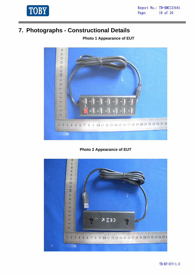
7. Photographs - Constructional Details Photo 1 Appearance of EUT
Photo 2 Appearance of EUT

Report No.: TB-EMC125641
Page: 19 of 20
TB-RF-075-1.0
Photo 3 Appearance of PCB
Photo 4 Appearance of PCB

Report No.: TB-EMC125641
Page: 20 of 20
TB-RF-075-1.0
8. Photographs – Test Setup Photo 1 Radiated Emission Test Setup
Photo 2 Electrostatic Discharge Test Setup