Embed Size (px)
Citation preview
Nuclear Engineering and Design 197 (2000) 183–195
Shielded containers for radioactive waste using recycledcontaminated metals
W.D. Richins a,*, T.E. Fewell a, H.J. Welland a, H.R. Sheely Jr. b
a Idaho National Engineering and En6ironmental Laboratory, PO Box 1625, MS 3760, Idaho Falls, ID 83415, USAb Lockheed Martin Energy Systems, PO Box 2003, K-1037, MS-7346, Oak Ridge, TN 37831, USA
Received 17 July 1998; received in revised form 12 July 1999; accepted 13 September 1999
Abstract
A family of shielded containers constructed of recycled contaminated lead and stainless steel from the USDeptartment of Energy (DOE) stockpile have been developed as a joint effort by the Idaho National Engineering andEnvironmental Laboratory and Lockheed Martin Energy Systems-Oak Ridge. The containers were designed primarilyfor the transportation and storage of 30- or 55-gallon drums of remote handled transuranic solid waste (RH-TRU).The use of recycled construction materials fulfills two purposes: (1) waste transportation and storage and (2) areduction in the quantity of contaminated metals that require both storage and disposal. Currently, the DOE complexhas millions of pounds of contaminated lead and stainless steel. Non-linear, dynamic finite element analyses were usedto simulate the drop tests onto a rigid surface required for US Deptartment of Transportation (DOT) 7A Type Acertification. During and after these tests, the container contents must remain within the container and shielding mustnot be reduced. Loads in the major connections and strains in the stainless steel and lead were monitored as afunction of time during dynamic impact analyses for three simulated drop orientations. Results were used to optimizethe final design. Stainless steel and lead were found to have maximum strains well below ultimate levels except at animpact corner where additional deformation is acceptable. The predicted loads in the connections indicate that someyielding will occur but the containment and shielding will remain intact. The results provide assurance that thecontainers will pass the required DOT certification tests. The methods used can be applied to other waste shippingcontainers allowing for optimization of designs without the expense of actual impact testing. © 2000 Elsevier ScienceS.A. All rights reserved.
www.elsevier.com/locate/nucengdes
1. Introduction
The Idaho National Engineering and Environ-mental Laboratory (INEEL) has about 700 drums
of remote handled solid transuranic waste (RH-TRU) that must be handled remotely due toradiation levels. The drums are currently stored insteel lined storage wells. The INEEL also storesapproximately two million pounds of slightly ra-dioactively contaminated lead identified as mixedhazardous waste. Costs for maintenance of thestorage facilities for these waste materials are veryhigh.
* Corresponding author. Tel.: +1-208-526-0522; fax: +1-208-526-0425.
E-mail address: [email protected] (W.D. Richins)
0029-5493/00/$ - see front matter © 2000 Elsevier Science S.A. All rights reserved.
PII: S0029 -5493 (99 )00267 -8
W.D. Richins et al. / Nuclear Engineering and Design 197 (2000) 183–195184
The INEEL Recycled Shielded Storage Con-tainer (RSSC) was developed primarily for thetransportation and storage of 30- and 55-gallondrums (113.6 or 208.2 l) of RH-TRU solid waste.The container allows for storing and handling ofthe RH-TRU drums using methods similar tothose used for contact handled transuranic waste.The shielding attenuates the radiation levels toless than 200 mR h−1 (2.0 mSv h−1) at thecontainer surface, which is the maximum doserate for contact handling.
The container design uses contaminated leadand stainless steel construction materials poten-tially fulfilling two purposes: (1) RH-TRU solidwaste transportation and storage and (2) reducingthe quantity of waste materials that require bothstorage and disposal. The funds designated forstorage and disposal of the contaminated materialcould potentially be used to construct the RSSC.This process will remove contaminated lead andstainless steel used from the waste stockpile thusconverting US DOE liabilities into usable assets.Several containers have been fabricated but not
yet tested to DOT 7A Type A requirements forradioactive solid waste shipping containers (USDOT, 1995; Westinghouse Hanford Co., 1995).
The results of the study show that a shieldedcontainer could be fabricated from contaminatedmaterials at reasonable costs. Several vendors cur-rently have the necessary licenses and facilities toprocess the contaminated materials and fabricatethe shielded containers.
2. Design concept
A family of similar containers have been devel-oped where the internal dimensions and/or thelead shielding thicknesses are varied to match thespecific requirements of the radioactive level anddimensions of the container contents. Containerscan be built, for example, with no lead shieldingfor contact handled 55-gallon waste drums, orwith sufficient shielding for a 30-gallon drum witha radioactive level of 5R h−1 (50 mSv h−1) on thedrum surface. Analysis of the 30-gallon wastedrum design is addressed in this paper.
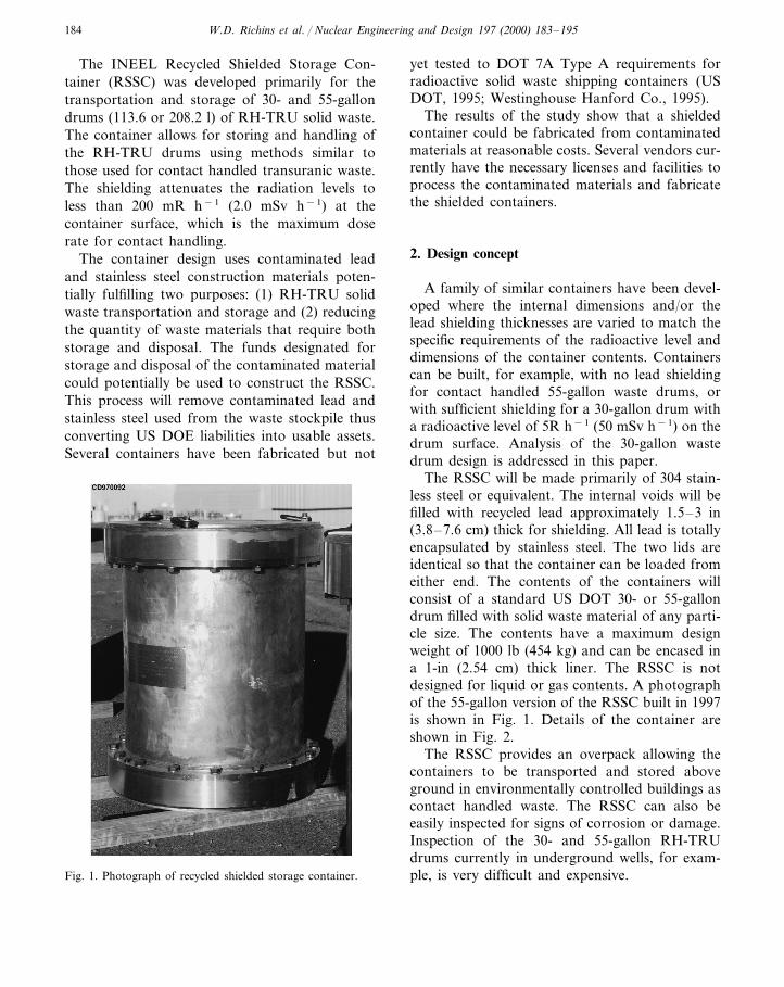
The RSSC will be made primarily of 304 stain-less steel or equivalent. The internal voids will befilled with recycled lead approximately 1.5–3 in(3.8–7.6 cm) thick for shielding. All lead is totallyencapsulated by stainless steel. The two lids areidentical so that the container can be loaded fromeither end. The contents of the containers willconsist of a standard US DOT 30- or 55-gallondrum filled with solid waste material of any parti-cle size. The contents have a maximum designweight of 1000 lb (454 kg) and can be encased ina 1-in (2.54 cm) thick liner. The RSSC is notdesigned for liquid or gas contents. A photographof the 55-gallon version of the RSSC built in 1997is shown in Fig. 1. Details of the container areshown in Fig. 2.
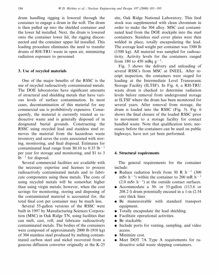
The RSSC provides an overpack allowing thecontainers to be transported and stored aboveground in environmentally controlled buildings ascontact handled waste. The RSSC can also beeasily inspected for signs of corrosion or damage.Inspection of the 30- and 55-gallon RH-TRUdrums currently in underground wells, for exam-ple, is very difficult and expensive.Fig. 1. Photograph of recycled shielded storage container.
W.D. Richins et al. / Nuclear Engineering and Design 197 (2000) 183–195 185
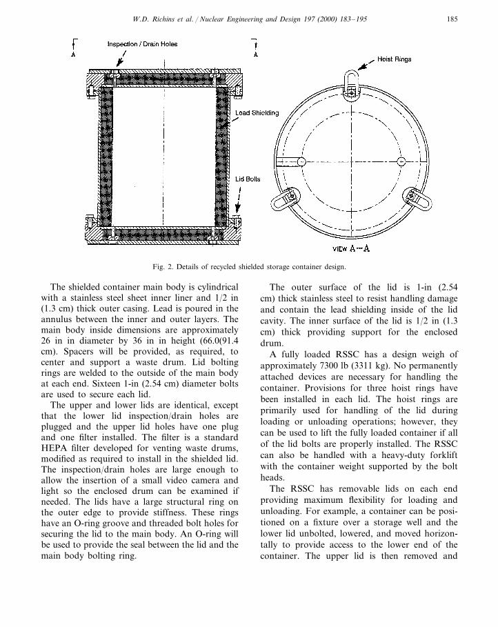
Fig. 2. Details of recycled shielded storage container design.
The shielded container main body is cylindricalwith a stainless steel sheet inner liner and 1/2 in(1.3 cm) thick outer casing. Lead is poured in theannulus between the inner and outer layers. Themain body inside dimensions are approximately26 in in diameter by 36 in in height (66.0(91.4cm). Spacers will be provided, as required, tocenter and support a waste drum. Lid boltingrings are welded to the outside of the main bodyat each end. Sixteen 1-in (2.54 cm) diameter boltsare used to secure each lid.
The upper and lower lids are identical, exceptthat the lower lid inspection/drain holes areplugged and the upper lid holes have one plugand one filter installed. The filter is a standardHEPA filter developed for venting waste drums,modified as required to install in the shielded lid.The inspection/drain holes are large enough toallow the insertion of a small video camera andlight so the enclosed drum can be examined ifneeded. The lids have a large structural ring onthe outer edge to provide stiffness. These ringshave an O-ring groove and threaded bolt holes forsecuring the lid to the main body. An O-ring willbe used to provide the seal between the lid and themain body bolting ring.
The outer surface of the lid is 1-in (2.54cm) thick stainless steel to resist handling damageand contain the lead shielding inside of the lidcavity. The inner surface of the lid is 1/2 in (1.3cm) thick providing support for the encloseddrum.
A fully loaded RSSC has a design weigh ofapproximately 7300 lb (3311 kg). No permanentlyattached devices are necessary for handling thecontainer. Provisions for three hoist rings havebeen installed in each lid. The hoist rings areprimarily used for handling of the lid duringloading or unloading operations; however, theycan be used to lift the fully loaded container if allof the lid bolts are properly installed. The RSSCcan also be handled with a heavy-duty forkliftwith the container weight supported by the boltheads.
The RSSC has removable lids on each endproviding maximum flexibility for loading andunloading. For example, a container can be posi-tioned on a fixture over a storage well and thelower lid unbolted, lowered, and moved horizon-tally to provide access to the lower end of thecontainer. The upper lid is then removed and
W.D. Richins et al. / Nuclear Engineering and Design 197 (2000) 183–195186
drum handling rigging is lowered through thecontainer to engage a drum in the well. The drumis then pulled up into the shielded container andthe lower lid installed. Next, the drum is loweredonto the container lower lid, the rigging discon-nected and the container upper lid installed. Thisloading procedure eliminates the need to transferdrums of RH-TRU waste in open air, minimizingradiation exposure to personnel.
3. Use of recycled materials
One of the major benefits of the RSSC is theuse of recycled radioactively contaminated metals.The DOE laboratories have significant amountsof structural and shielding metals that have vari-ous levels of surface contamination. In mostcases, decontamination of this material for anycommercial use is prohibitively expensive. Conse-quently, the material is currently treated as ra-dioactive waste and is generally disposed of indesignated burial grounds. Constructing theRSSC using recycled lead and stainless steel re-moves the material from the hazardous wasteinventory and saves the costs associated with stor-ing, monitoring, and final disposal. Estimates forcontaminated lead range from $0.10 to 0.35 lb−1
per year for storage and monitoring, and $1 to 3lb−1 for disposal.
Several commercial facilities are available withthe necessary expertise and licenses to processradioactively contaminated metals and to fabri-cate components using these metals. The costs ofusing recycled metals will be somewhat higherthan using virgin metals; however, when the costsavings for monitoring, storing and disposing ofthe contaminated material is accounted for, thetotal final cost per container may be much less.
Several 55-gallon versions of the RSSC werebuilt in 1997 by Manufacturing Sciences Corpora-tion (MSC) in Oak Ridge TN, using facilities thatcan melt, cast, roll, and fabricate radioactivelycontaminated metals. The bodies of the containerswere composed of approximately 2000 lb (910 kg)of 304 stainless steel produced by melting contam-inated carbon steel and nickel recovered from agaseous diffusion converter originally at the K-25
site, Oak Ridge National Laboratory. This feedstock was supplemented with clean chromium inorder to make the 304 alloy. MSC cast contami-nated lead from the DOE stockpile into the steelcontainers. Stainless steel cover plates were thenwelded in place, totally encapsulating the lead.The average lead weight per container was 3300 lb(1500 kg). All material was sampled for radioac-tivity. Activity levels for the containers rangedfrom 180 to 450 mBq g−1.
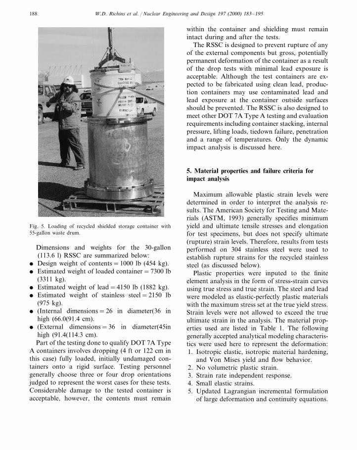
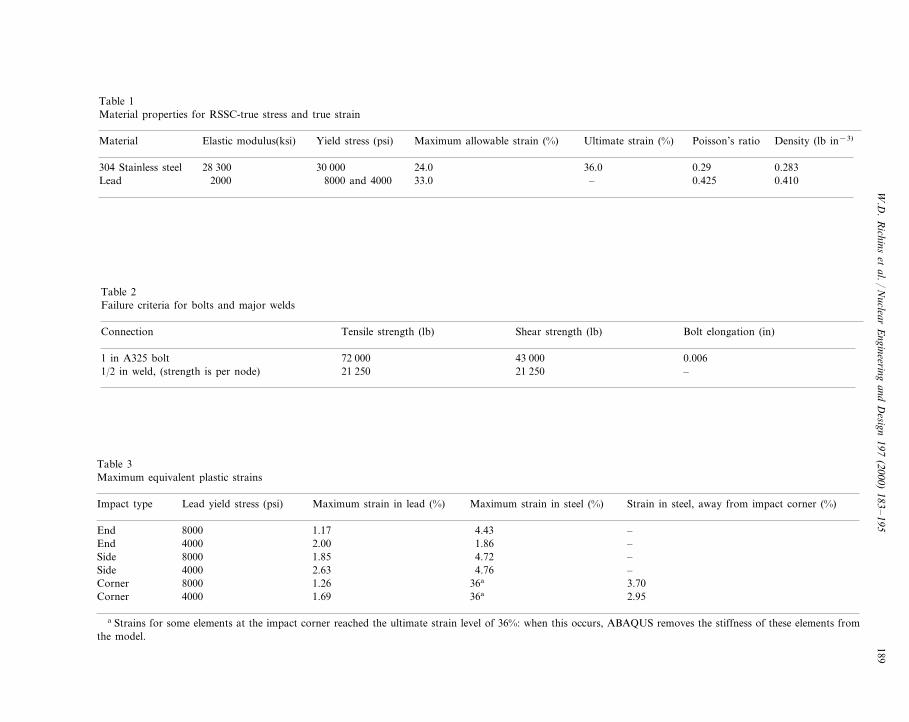
Fig. 3 shows the delivery and unloading ofseveral RSSCs from MSC at INEEL. After re-ceipt inspection, the containers were staged forloading at the Intermediate Level TransuranicStorage Facility (ILTSF). In Fig. 4, a RH-TRUwaste drum is checked to determine radiationlevels before removal from underground storageat ILTSF where the drum has been monitored forseveral years. After removal from storage, thedrum is loaded into the RSSC (Fig. 5). Fig. 6shows the final closure of the loaded RSSC priorto movement to a storage facility for contacthandled waste. Note that qualification tests, nec-essary before the containers can be used on publichighways, have not yet been performed.
4. Structural requirements
The general requirements for the containerinclude:� Reduce radiation levels from 30 R h−1 (300
mSv h−1) within the container to 200 mR h−1
(2.0 mSv h−1) at the outside contact surfaces.� Accommodate a 30- or 55-gallon (113.6 or
208.2 l) drum potentially encased in a 1-in (2.54cm) thick liner.
� Be maneuverable with standard transportequipment.
� Totally encapsulate the lead shielding.� Facilitate operational activities.� Be stackable.� Include ports for venting, sampling, and video
access.� Minimize cost.� Meet DOT 7A Type A requirements for ra-
dioactive solid waste shipping containers.

W.D. Richins et al. / Nuclear Engineering and Design 197 (2000) 183–195 187
Fig. 3. Delivery of recycled shielded storage containers.
Fig. 4. Removal of 55-gallon waste drum from underground storage.
W.D. Richins et al. / Nuclear Engineering and Design 197 (2000) 183–195188
Fig. 5. Loading of recycled shielded storage container with55-gallon waste drum.
within the container and shielding must remainintact during and after the tests.
The RSSC is designed to prevent rupture of anyof the external components but gross, potentiallypermanent deformation of the container as a resultof the drop tests with minimal lead exposure isacceptable. Although the test containers are ex-pected to be fabricated using clean lead, produc-tion containers may use contaminated lead andlead exposure at the container outside surfacesshould be prevented. The RSSC is also designed tomeet other DOT 7A Type A testing and evaluationrequirements including container stacking, internalpressure, lifting loads, tiedown failure, penetrationand a range of temperatures. Only the dynamicimpact analysis is discussed here.
5. Material properties and failure criteria forimpact analysis
Maximum allowable plastic strain levels weredetermined in order to interpret the analysis re-sults. The American Society for Testing and Mate-rials (ASTM, 1993) generally specifies minimumyield and ultimate tensile stresses and elongationfor test specimens, but does not specify ultimate(rupture) strain levels. Therefore, results from testsperformed on 304 stainless steel were used toestablish rupture strains for the recycled stainlesssteel (as discussed below).
Plastic properties were inputed to the finiteelement analysis in the form of stress-strain curvesusing true stress and true strain. The steel and leadwere modeled as elastic-perfectly plastic materialswith the maximum stress set at the true yield stress.Strain levels were not allowed to exceed the trueultimate strain in the analysis. The material prop-erties used are listed in Table 1. The followinggenerally accepted analytical modeling characteris-tics were used here to represent the deformation:1. Isotropic elastic, isotropic material hardening,
and Von Mises yield and flow behavior.2. No volumetric plastic strain.3. Strain rate independent response.4. Small elastic strains.5. Updated Lagrangian incremental formulation
of large deformation and continuity equations.
Dimensions and weights for the 30-gallon(113.6 l) RSSC are summarized below:
� Design weight of contents=1000 lb (454 kg).� Estimated weight of loaded container=7300 lb
(3311 kg).� Estimated weight of lead=4150 lb (1882 kg).� Estimated weight of stainless steel=2150 lb
(975 kg).� (Internal dimensions=26 in diameter(36 in
high (66.0(91.4 cm).� (External dimensions=36 in diameter(45in
high (91.4(114.3 cm).Part of the testing done to qualify DOT 7A Type
A containers involves dropping (4 ft or 122 cm inthis case) fully loaded, initially undamaged con-tainers onto a rigid surface. Testing personnelgenerally choose three or four drop orientationsjudged to represent the worst cases for these tests.Considerable damage to the tested container isacceptable, however, the contents must remain
W.D
.R
ichinset
al./N
uclearE
ngineeringand
Design
197(2000)
183–
195189
Table 1Material properties for RSSC-true stress and true strain
Ultimate strain (%) Poisson’s ratio Density (lb in−3)Elastic modulus(ksi)Material Yield stress (psi) Maximum allowable strain (%)
0.2928 300 0.28330 000 24.0 36.0304 Stainless steel0.4102000 0.425–Lead 33.08000 and 4000
Table 2Failure criteria for bolts and major welds
Connection Tensile strength (lb) Shear strength (lb) Bolt elongation (in)
72 000 43 000 0.0061 in A325 bolt21 2501/2 in weld, (strength is per node) 21 250 –
Table 3Maximum equivalent plastic strains
Impact type Lead yield stress (psi) Maximum strain in lead (%) Maximum strain in steel (%) Strain in steel, away from impact corner (%)
8000End 1.17 4.43 –4000 2.00 1.86End –8000 1.85Side 4.72 –
Side 4000 2.63 4.76 –Corner 8000 1.26 36a 3.70
4000 1.69 36aCorner 2.95
a Strains for some elements at the impact corner reached the ultimate strain level of 36%: when this occurs, ABAQUS removes the stiffness of these elements fromthe model.
W.D. Richins et al. / Nuclear Engineering and Design 197 (2000) 183–195190
The DOE Rocky Flats facility (Coubrough etal., 1992) conducted tests to determine theformability of 304 stainless steel sheet concludingthat 304 sheet ruptures at about 36% effective(equivalent) plastic strain in a worst case biaxialstress state. In uniaxial tension tests, the effectivestrain at rupture is much higher. The failure strainoccurring in the worst case biaxial tension shouldbe a reasonable lower bound for essentially allstress states occurring in the RSSC. The maxi-mum effective plastic strain was taken as 2/3 of 36or 24% for these analyses in order to assure amargin of safety.
The lead properties were taken from Shappert(1970). Since the dynamic tensile strength of leadis not well known, two load cases were analyzedfor each impact orientation using lead strengths of8000 and 4000 psi (55.2 and 27.6 MPa). Using8000 psi should provide an upper bound onthe forces developed throughout the model whileusing 4000 psi should maximize the displace-ments.
The failure criteria used for the lid bolts and the1/2 in (1.3 cm) welds attaching the rings and 1-in
(2.54 cm) plates are listed in Table 2. The con-tainer welds were conservatively assumed to havethe same elastic properties as the 304 stainlesssteel. Note that the failure criteria in Table 2 donot allow the bolt or weld material to yield.Considerable deformation can generally takeplace in these connections before failure actuallyoccurs.
6. Method of analysis
The RSSC was modeled using I-DEAS (Struc-tural Dynamics Research Corp., 1995) for solidmodeling, finite element mesh generation and ap-plying loads and boundary conditions. The modelwas then converted to ABAQUS Explicit (Hib-bitt, Karlsson, and Sorenson, Inc., 1995) formatfor all analysis and post processing of analysisresults. The capabilities of ABAQUS Explicitwere needed to: (1) treat interactions within thecontainer (sliding surfaces, friction and contactbetween the various parts), (2) model weld andbolt yield strengths, (3) analyze the effects of
Fig. 6. Sealing lid of recycled shielded storage container.
W.D. Richins et al. / Nuclear Engineering and Design 197 (2000) 183–195 191
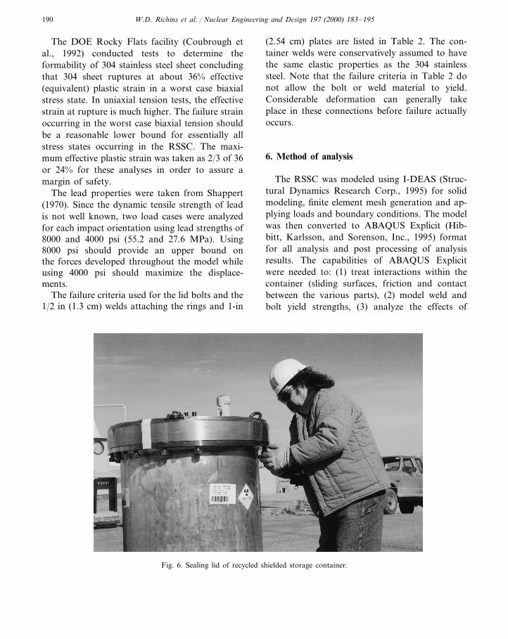
Fig. 7. ABAQUS finite element model.
dynamic impacts and (4) model the inelastic prop-erties of lead and stainless steel.
A single model was developed to address allimpact orientations. A half model was used sincethe container and all load cases have symmetryabout a plane through the axis of the container.Symmetry boundary conditions were applied tonodes on this plane. Nominal values for the di-mensions were used throughout in creating thesolid model. Some minor details such as the filter/plug arrangement in the lids, sheet metal weldsand rubber seals were ignored. A rigid surface wasused to simulate the impact. The global coordinatesystem was rotated for the corner impact load caseto facilitate the definition of the initial velocity andrigid impact surface. Details of the finite elementmodel are shown in Fig. 7 and Fig. 8.
Two types of elements were used: (1) 8-nodelinear bricks (ABAQUS type C3D8R) used torepresent solid lead or thick stainless steel and (2)4-node thin shells (ABAQUS type S4R) used torepresent sheet stainless steel or thin plates. Theseelements, when well proportioned, generally allowfor smooth convergence for large displacement
solutions. Element density was increased in areaswithin the model where contact and/or highstrains were expected. The elements representingstainless steel and lead are shown in Fig. 7. A totalof 15, 121 elements were used.
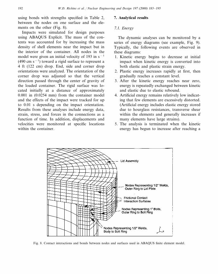
The solid models were partitioned, prior tomeshing, to segregate the regions with lead andsteel. No slippage was allowed between the leadand the steel elements. Contact surfaces (see Fig.8) were defined to represent the mating surfacesbetween the lids and the container body. Thesecontact surfaces allow frictional sliding betweenthe elements when they come in contact withoutpenetration of the elements on one surface bythose on the other. The surfaces as modeled wereinitially in contact. Where the stainless steel wasmodeled with thin shell elements, the contact sur-face was offset to half the thickness of the shell.ABAQUS automatically accounts for this dis-tance, so that the surfaces have initial contact. Afriction coefficient of 0.4 was used (stainless steelon stainless steel). The major welds attaching the1-in (2.54 cm) thick lid plates and bolt rings andthe 1-in (2.54 cm) diameter bolts were modeled
W.D. Richins et al. / Nuclear Engineering and Design 197 (2000) 183–195192
using bonds with strengths specified in Table 2,between the nodes on one surface and the ele-ments on the other (Fig. 8).
Impacts were simulated for design purposesusing ABAQUS Explicit. The mass of the con-tents was accounted for by increasing the massdensity of shell elements near the impact but inthe interior of the container. All nodes in themodel were given an initial velocity of 193 in s−1
(490 cm s−1) toward a rigid surface to represent a4 ft (122 cm) drop. End, side and corner droporientations were analyzed. The orientation of thecorner drop was adjusted so that the verticaldirection passed through the center of gravity ofthe loaded container. The rigid surface was lo-cated initially at a distance of approximately0.001 in (0.0254 mm) from the container modeland the effects of the impact were tracked for upto 0.01 s depending on the impact orientation.Results from these analyses include energy data,strain, stress, and forces in the connections as afunction of time. In addition, displacements andvelocities were monitored at specific locationswithin the container.
7. Analytical results
7.1. Energy
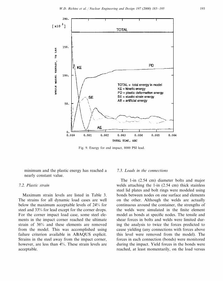
The dynamic analyses can be monitored by aseries of energy diagrams (see example, Fig. 9).Typically, the following events are observed inthese diagrams:1. Kinetic energy begins to decrease at initial
impact when kinetic energy is converted intoboth elastic and plastic strain energy.
2. Plastic energy increases rapidly at first, thengradually reaches a constant level.
3. After the kinetic energy reaches near zero,energy is repeatedly exchanged between kineticand elastic due to elastic rebound.
4. Artificial energy remains relatively low indicat-ing that few elements are excessively distorted.(Artificial energy includes elastic energy storeddue to hourglass resistances, transverse shearwithin the elements and generally increases ifmany elements have large strains).
5. The analysis is terminated when the kineticenergy has begun to increase after reaching a
Fig. 8. Contact interactions and bonds between nodes and surfaces used in ABAQUS finite element model.
W.D. Richins et al. / Nuclear Engineering and Design 197 (2000) 183–195 193
Fig. 9. Energy for end impact, 8000 PSI lead.
minimum and the plastic energy has reached anearly constant value.
7.2. Plastic strain
Maximum strain levels are listed in Table 3.The strains for all dynamic load cases are wellbelow the maximum acceptable levels of 24% forsteel and 33% for lead except for the corner drops.For the corner impact load case, some steel ele-ments in the impact corner reached the ultimatestrain of 36% and these elements are removedfrom the model. This was accomplished usingfailure criterion available in ABAQUS explicit.Strains in the steel away from the impact corner,however, are less than 4%. These strain levels areacceptable.
7.3. Loads in the connections
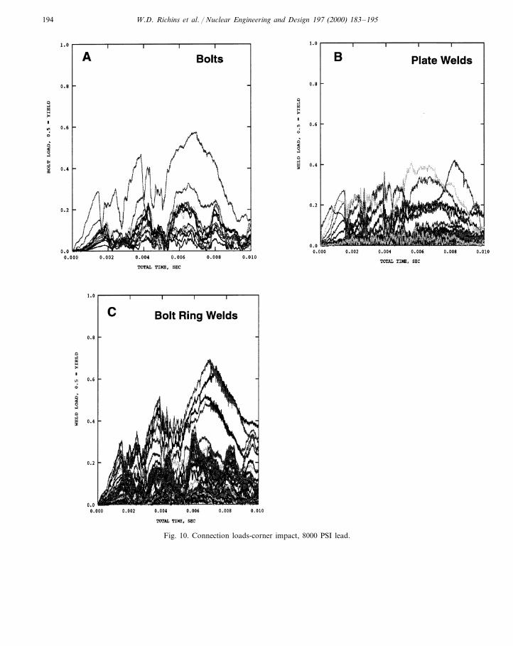
The 1-in (2.54 cm) diameter bolts and majorwelds attaching the 1-in (2.54 cm) thick stainlesssteel lid plates and bolt rings were modeled usingbonds between nodes on one surface and elementson the other. Although the welds are actuallycontinuous around the container, the strengths ofthe welds were simulated in the finite elementmodel as bonds at specific nodes. The tensile andshear forces in bolts and welds were limited dur-ing the analysis to twice the forces predicted tocause yielding (any connections with forces abovethis level were removed from the model). Theforces in each connection (bonds) were monitoredduring the impact. Yield forces in the bonds werereached, at least momentarily, on the load versus
W.D. Richins et al. / Nuclear Engineering and Design 197 (2000) 183–195194
Fig. 10. Connection loads-corner impact, 8000 PSI lead.
W.D. Richins et al. / Nuclear Engineering and Design 197 (2000) 183–195 195
time diagrams (examples shown in Fig. 10), whenthe load ratio reached 0.5. The analyses producedrecords of the maximum calculated forces andprovided information used to design the bolts andwelds.
A corner impact load case was analyzed wherethe bolts and welds were allowed to fail whenyield was reached. The connections were thenremoved from the model for the remainder of theanalysis with no bond strength assumed at theconnection. All other connections remained intactwithout any continued failures.
The loads in the bolts and welds for the dy-namic load cases for the RSSC generally remainat or below yield strengths during these impacts,only momentarily slightly exceeding yield atsome locations. Since the actual dynamicstrengths for the welds and bolts are above thosepredicted and yielding does not necessarily implyconnection failure, these results are consideredacceptable.
8. Conclusions
Conclusions drawn from this study are:� A family of containers have been designed for
the storage and transportation of RH-TRUsolid waste utilizing radioactive scrap metals.
� The containers will allow the storage of RH-TRU solid waste (due to the lead shieldingprovided by the containers) as contact handledmaterial.
� Since the metals used in construction are ra-dioactively contaminated materials currentlystored in DOE facilities, the costs of manufac-turing the containers can be offset by the sav-ing in waste storage and disposal.
� Non-linear, dynamic finite element analyseswere used to optimize the final design. Theresults provide assurance that the containerswill pass DOT impact tests when qualificationtests are performed.
� The methods used can be applied to otherwaste shipping containers allowing for opti-
mization of designs without the expense ofactual impact testing.
9. Notice
This paper was prepared as an account of worksponsored by an agency of the US Government.Neither the US Government nor any agencythereof, or any of their employees, makes anywarranty, expressed or implied, or assumes anylegal liability or responsibility for any thirdparty’s use, or the results of such use, of anyinformation, apparatus, product or process dis-closed in this report, or represents that its use bysuch third party would not infringe privatelyowned rights. The views expressed in this paperare not necessarily those of the US DOE.
Acknowledgements
Work supported by the US Department ofEnergy, Idaho Field Office, under DOE, contractnumber: DE-AC07-94ID13223.
References
American Society for Testing and Materials: Annual Book ofASTM Standards (1993).
Coubrough, G.J., Matlock, D.K., VanTyne, C.J., December1992. Formability of Type 304 Stainless Steel Sheet: EGand G-Rocky Flats Plant, Report Number RFP-4607.
ABAQUS Explicit 5.4 (1995). Hibbitt, Karlsson and Sorenson,Incorporation, Providence, RI.
Shappert, L.B., February 1970. A Guide for the Design,Fabrication, and Operation of Shipping Casks for NuclearApplication, ORNL-NSIC-68. Oakridge National Labora-tory, Oakridge, TN.
I-DEAS: Master Series 2.1 (1995). Structural Dynamics Re-search Corporation, Milford, OH.
US Department of Transportation, Hazardous Materials:Transportation Regulations; Compatibility with Regula-tions of the International Atomic Energy Agency; FinalRule, Federal Register, vol. 60 (September 1995), pp.171–177.
Regulator Compliance Guide for DOT-7A Type A PackagingDesign: Rev. 1, Draft, WHC-SD-TP-RPT-017 (1995).Westinghouse Hanford Company.