Embed Size (px)
Citation preview

.
Ship Inspection Report (SIRE) Programme
Vessel Inspection Questionnaires for Oil Tankers, Combination Carriers, Shuttle Tankers,
Chemical Tankers and Gas Tankers, Seventh Edition (VIQ 7)
17 September 2018
Oil Companies International Marine Forum

© Copyright OCIMF 2018. All rights reserved. VIQ 7 – 17 September 2018 2
Record of Revisions

© Copyright OCIMF 2018. All rights reserved. VIQ 7 – 17 September 2018 3

© Copyright OCIMF 2018. All rights reserved. VIQ 7 – 17 September 2018 4
INDEX
Section 1. 5
Section 2. 7
Section 3. 8
Section 4. 10
Section 5. 13
Chapter 1. General Information 14
Chapter 2. Certification and Documentation 17
Chapter 3. Crew Management 24
Chapter 4. Navigation and Communications 28
Chapter 5. Safety Management 44
Chapter 6. Pollution Prevention 66
Chapter 7. Maritime Security 72
Chapter 8. Cargo and Ballast Systems - Petroleum 76
Chapter 8. Cargo and Ballast Systems - Chemicals 95
Chapter 8. Cargo and Ballast Systems - LPG 112
Chapter 8. Cargo and Ballast Systems - LNG 132
Chapter 9. Mooring 151
Chapter 10. Engine and Steering Compartments 158
Chapter 11. General Appearance and Condition 172
Chapter 12. Ice Operations 175
© Copyright OCIMF 2018. All rights reserved. VIQ 7 – 17 September 2018 5
SECTION 1 1.1 History of the SIRE Programme In 1993, OCIMF established a Ship Inspection Report (SIRE) Programme, which enabled OCIMF members to submit their ship inspection reports to OCIMF for distribution to OCIMF members and certain qualifying non-OCIMF members. Participation in the original programme, as either an inspecting OCIMF Member or a programme recipient, was strictly voluntary and each programme recipient determined independently how to evaluate the information contained in the reports received from OCIMF.
Under the SIRE Programme, the operator of any ship that is the subject of a report was given a copy of that report and the opportunity to submit written comments relating to the report, to both the inspecting OCIMF Member and to OCIMF. Report recipients accessed the SIRE System Index by computer and this permitted the index to be viewed or downloaded. Programme recipients could order reports and any matching operator comments from the SIRE system. Reports and comments were transmitted by facsimile to the programme recipients' pre-registered facsimile numbers on request. 1.2 Revisions to the Programme The original SIRE Programme was first revised in 1997 and introduced the means whereby programme recipients were able to receive reports and any operator comments electronically, as well as by facsimile. Two major changes were also introduced in the 1997 Revised Programme. These were:
1. A Uniform Vessel Inspection Procedure; and, 2. A Vessel Particular Questionnaire (VPQ)1
The SIRE Programme was again revised in 2000. The 2004 revisions made further important changes to the inspection procedure whilst also adding numerous new vessel types that are inspected under the programme.2 Collectively, these are referred to herein as “Vessels”. Subsequent revisions updated the VIQ questions and guidance but did not add any questions. This 2011 Edition substantially changed the focus of the VIQ to increase the emphasis of the inspection on navigation procedures and cargo and ballast handling operations. Consequently, significant changes have been made in this edition. In 2013 a further major revision of the VIQ was undertaken. 1.3 Uniform Vessel Inspection Procedure
The programme requires that participating submitting companies follow a uniform Vessel Inspection Procedure. This procedure has an Inspection Element and a Report Element.
1 Under the Original 1993 Programme, the inspecting OCIMF Member was free to choose whatever inspection protocol and report format it desired. In 1997, the Uniform Vessel Inspection Procedure changed this. The Vessel Particular Questionnaire was a newly developed OCIMF document, also introduced in 1997 and was not part of the original programme. The Vessel Inspection Questionnaire was further revised in 2000, and the Vessel Particulars Questionnaire was also revised in 2003 when a Harmonised Vessel Particulars Questionnaire (HVPQ) was introduced. Updated VIQs were published in 2004, 2005, 2008, 2009,2012 and 2014.
2 The SIRE Programme was expanded in 2005 to include the inspection of barges carrying petroleum products, chemicals, or gas, or vessels used in the carriage of packaged petroleum products or gas, or road tankers carrying the same commodities. Towing vessels that are utilised in the handling of barges carrying the above listed products may also be inspected under the SIRE Programme. The inspection of these vessels and associated questionnaires are addressed in separate questionnaires.

© Copyright OCIMF 2018. All rights reserved. VIQ 7 – 17 September 2018 6
The Inspection Element uses a series of detailed inspection questionnaires as appropriate for the type of vessel inspected. These questionnaires address issues associated with safety and pollution prevention. Inspectors who are employed or contracted by submitting companies must (with certain exceptions) answer all these questions. Questions are, in many cases, accompanied by guidance notes and/or references to source documents. Their purpose is to aid the Inspector’s response.
The Report Element is developed from the completed electronic questionnaire that is submitted by the Inspector, either directly to the SIRE web site, or to the submitting company for further processing prior to transmission to the vessel operator and to SIRE.

© Copyright OCIMF 2018. All rights reserved. VIQ 7 – 17 September 2018 7
SECTION 2 2.1 The Vessel Inspection Questionnaires, ROVIQ and VIQ Computer
Programmes The 3rd Edition revisions to the SIRE Vessel Inspection Questionnaires and their accompanying Inspection Reports introduced significant changes to the scope and presentation of the Programme. These were: 1. The inspection of oil tankers (together with combination carriers and shuttle tankers), chemical carriers
and gas carriers. Under the revised Programme, these vessels are categorised by size. 2. The inspection of barges carrying petroleum products, chemicals, or gas, or vessels used in the carriage
of packaged petroleum products or gas or road tankers carrying the same commodities, and also towing vessels that are utilised in the handling of barges carrying the above listed products. Collectively, in the VIQ documents, the inspection questionnaires that are used are referred to as “Vessel Inspection Questionnaires” (“VIQs”)
3. The key question and sub-question concept used in the 1st and 2nd Editions of the VIQ was discontinued
in the 3rd and subsequent editions and replaced (except in a few cases) with individual questions. As in the case of previous editions, however, the “Yes” “No”, “Not Seen” or “Not Applicable” responses are utilised.
2.2 Reorganised Vessel Inspection Questionnaire (ROVIQs) The Reorganised Vessel Inspection Questionnaire (ROVIQs) were a feature introduced with the SIRE revisions in 2000. The Reorganised Vessel Inspection Questionnaire (ROVIQs) organised the VIQ questions and guidance notes to follow the order of the route that would normally be taken by an inspector in the course of an inspection3. As in the case of the previous editions of the VIQ, Reorganised Vessel Inspection Questionnaire (ROVIQs) will be used with this 2018 Edition that set out the questions into the approximate order that an inspector is likely to encounter them during the course of an inspection. Selection of the questionnaire to be used for each particular inspection is made using a “Vessel Selection Wizard” incorporated into the SIRE Report Editor Software programme. This Wizard requires a series of questions to be answered. When the Wizard is completed, the appropriate questionnaire can be printed in a number of different formats, or in the format of the Reorganised Vessel Inspection Questionnaire (ROVIQ). These Questionnaires must be used during each inspection. The inspection findings must be transferred from the pocketbook to the appropriate VIQ computer programme after the inspection is completed.
3 Each Reorganised Vessel Inspection Questionnaire (ROVIQs) is laid out on the assumption that an inspection takes the following course: a review of the vessel’s Documentation, followed by an inspection of the Wheelhouse and Navigation, Communications, General external areas (including Mooring, Main Deck and Pumproom), Cargo Control Room, Engine and Steering Compartments and finally, the Accommodation.

© Copyright OCIMF 2018. All rights reserved. VIQ 7 – 17 September 2018 8
SECTION 3 3.1 Using the SIRE Vessel Inspection Questionnaires (“VIQs”) The inspection questionnaires used in this programme contain a series of questions related to safety and pollution prevention applicable to the type of vessel that is inspected. These questions are consecutively numbered and are logically grouped into separate chapters. Each chapter contains a series of questions to be answered by the inspector. Questions may be accompanied by guidance, namely:
1. Guidance notes to inspectors; 2. Reference source(s) citing regulation(s) or industry guidelines pertaining to questions; and 3. An indicator to identify issues when an inspector comment is mandatory.
The above-mentioned guidance, regulatory/industry references amplify the questions, and these are provided to assist the inspector to answer the questions. If the guidance and references lead the inspector to conclude that the question should be answered positively, the box “Yes” in the VIQ computer programme should be checked. On the other hand, if the guidance and any reference sources indicate to the inspector that the question should be answered negatively, the “No” box should be checked.4 Where appropriate, the “Not Seen” or “Not Applicable” box should be ticked. The inspector must respond to all the questions appropriate to the type of vessel being inspected. Failure to do this will mean that the inspection report cannot be transmitted to the SIRE Internet site for processing by the principal who commissioned the inspection. The inspector must insert an Observation when responding to any question where the response box is marked “No”. The Observation must specify and explain the reason why a negative response is made. Additionally, where a box is marked “Not Seen”, the reason for the “Not Seen response must be given in the Observation section accompanying the question. In cases where a “Not Applicable” response is required, the “Not Applicable” response is treated in the same way as a “Yes” response and there is no requirement for the reason to be made in the Observations section accompanying the question. However, if, in the inspector’s judgment an explanatory comment is necessary, the inspector may make such comment in the “Comments” section accompanying the question provided such comment makes amplification to assist the understanding of a report recipient as to an issue associated with a specific question. In some cases, where the type of vessel being inspected results in one or more questions being not applicable to that type of vessel, the Report Editor is programmed to automatically answer those questions “Not Applicable”. In many cases, the question does not have a “Not Applicable” option. For some questions, where the guidance note is highlighted, the inspector is required to provide comment as required by the highlighted section of guidance. This requirement is flagged in the printed VIQ by highlighted, italic text in the guidance notes. In the electronic Report Editor software, it is highlighted in yellow. At the end of each chapter there is an Additional Comments section. If the inspector has additional comments in respect of subject matter that is not covered by the specific questions in the chapter, the inspector may make such comments in the Additional Comments section.
4 Some Questions do not have guidance, in such cases; the Inspector is required to make an unaided answer.
© Copyright OCIMF 2018. All rights reserved. VIQ 7 – 17 September 2018 9
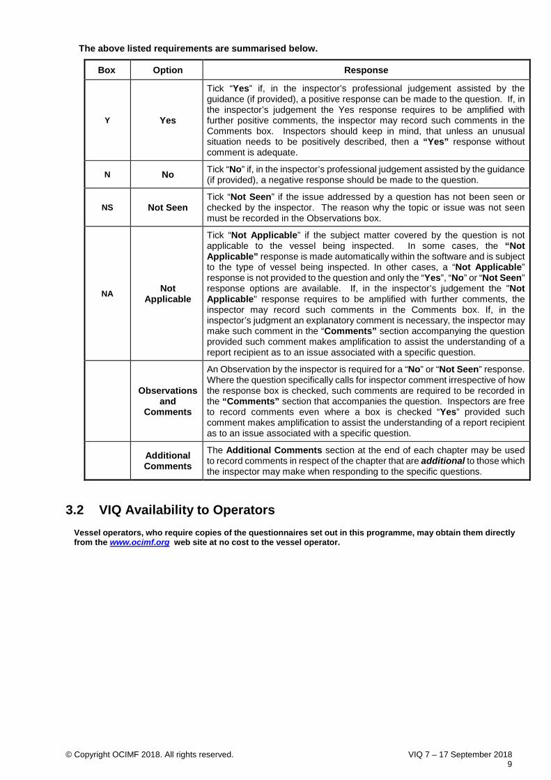
The above listed requirements are summarised below.
Box Option Response
Y Yes
Tick “Yes” if, in the inspector’s professional judgement assisted by the guidance (if provided), a positive response can be made to the question. If, in the inspector’s judgement the Yes response requires to be amplified with further positive comments, the inspector may record such comments in the Comments box. Inspectors should keep in mind, that unless an unusual situation needs to be positively described, then a “Yes” response without comment is adequate.
N No Tick “No” if, in the inspector’s professional judgement assisted by the guidance (if provided), a negative response should be made to the question.
NS Not Seen Tick “Not Seen” if the issue addressed by a question has not been seen or checked by the inspector. The reason why the topic or issue was not seen must be recorded in the Observations box.
NA Not Applicable
Tick “Not Applicable” if the subject matter covered by the question is not applicable to the vessel being inspected. In some cases, the “Not Applicable” response is made automatically within the software and is subject to the type of vessel being inspected. In other cases, a “Not Applicable” response is not provided to the question and only the “Yes”, “No” or “Not Seen” response options are available. If, in the inspector’s judgement the "Not Applicable" response requires to be amplified with further comments, the inspector may record such comments in the Comments box. If, in the inspector’s judgment an explanatory comment is necessary, the inspector may make such comment in the “Comments” section accompanying the question provided such comment makes amplification to assist the understanding of a report recipient as to an issue associated with a specific question.
Observations
and Comments
An Observation by the inspector is required for a “No” or “Not Seen” response. Where the question specifically calls for inspector comment irrespective of how the response box is checked, such comments are required to be recorded in the “Comments” section that accompanies the question. Inspectors are free to record comments even where a box is checked “Yes” provided such comment makes amplification to assist the understanding of a report recipient as to an issue associated with a specific question.
Additional Comments
The Additional Comments section at the end of each chapter may be used to record comments in respect of the chapter that are additional to those which the inspector may make when responding to the specific questions.
3.2 VIQ Availability to Operators
Vessel operators, who require copies of the questionnaires set out in this programme, may obtain them directly from the www.ocimf.org web site at no cost to the vessel operator.

© Copyright OCIMF 2018. All rights reserved. VIQ 7 – 17 September 2018 10
SECTION 4
Conduct of Inspections
4.1 Mandatory Inspection Requirements The following mandatory inspection requirements must be followed by inspectors in the conduct of their shipboard inspection in order for reports to meet the requirements of the SIRE Programme:
4.1.1 General Requirements. 1. The inspector must introduce themselves to the Master or the Master’s authorised deputy, explain
the scope of the inspection and discuss the preferred order in which it will be carried out, prior to commencement of the inspection. Inspectors should co-operate fully to conduct the inspection in the order that will cause the least disruption to the vessel’s operations. The inspector must be accompanied by a member of the ship's staff at all times during the course of the inspection.
2. The inspector must set a good example with respect to their communications, behaviour and own personal safety procedures whilst on board the vessel and in the terminal and must wear appropriate personal protection equipment at all times.
3. Electrical or electronic equipment of non-approved type, whether mains or battery powered, must not be active, switched on or used within any gas-hazardous or other hazardous areas. This includes torches, radios, mobile telephones, calculators, computers, photographic equipment and any other portable equipment that is electrically powered but not approved for operation in a gas-hazardous area. It should be borne in mind that equipment such as mobile telephones and smart watches, if switched on, can be activated remotely and a hazard can be generated by the alerting or calling mechanism and, in the case of mobile telephones, by the natural response to answer the call. Any specific Terminal requirements must be adhered to.
4. Any Observations that the inspector intends to record in the VIQ must be pointed out and discussed ‘on site’ at the time with the member of the ship's staff assigned to accompany the inspector. This ensures that the nature of the Observations are fully understood and can also avoid extended discussion at the end of the inspection.
5. On completion of the inspection, some Submitting Companies require the inspector to provide a list of the inspection findings in the form of written observations, others do not. In either case, the inspector must discuss the inspection findings with the Master or the Master's authorised deputy before leaving the vessel. Other than to prepare these observations, however, the inspector must not remain on the vessel to complete the inspection report. It is recognised that on occasions this may not be possible, especially when leaving and joining the vessel is done by helicopter on vessels doing STS operations.
6. The guide time for an inspection as specified in 4.3.4 below is 8-10 hours and as a guide the documentation checks should not exceed 3 hours, and this time should be used to conduct the inspection of the vessel, interact with crewmembers, compile the observation list if appropriate, and conduct the close out meeting. The completion of the report using the report editor software before the inspector leaves the vessel must not occur as this reduces the time that the inspector will spend conducting the physical inspection of the vessel. As specified in 4.1.1.5 above, the inspector must leave the vessel on completion of the inspection and must not remain on board to complete entering the report details into the report editor.
7. The guide time as specified below in 4.3.4 is 8-10 hours, however the actual time to conduct the inspection will be greater than this taking in account travel time to and from the vessel. All inspectors must take into account their own rest hours and fatigue levels when conducting inspections. ‘Back to back’ inspections are discouraged, and inspectors should complete and submit the report for one vessel before commencing an inspection on another vessel.

© Copyright OCIMF 2018. All rights reserved. VIQ 7 – 17 September 2018 11
4.1.2 Additional Requirements. In addition to the general mandatory requirements list above, the Inspector: - 1. Must respond by entering the requested information or by checking one response box for each
question;
2. Must, where guidance to a question is provided, consider all the guidance to determine how the question should be answered;
3. Must carefully consider and provide a proper response to every question;
4. Must use objective evidence when answering each question (the assurance of the vessel’s staff is insufficient evidence or proof);
5. Must include an explanatory Observation in the Observation section that accompanies a question when it is answered “No” or “Not Seen”. Where the VIQ question is answered “Not Applicable” or in cases where the guidance requires a comment regardless of how a question is answered, such comment must be recorded in the “Comments” section.
6. Must not use a “Yes” response to any question where an inspector’s Observation or Other comment contains negative elements (if there is such negative Observation or Other comment then the answer to that question should be “No”);
7. Must not, in any Other Comment or Additional Comments, include -
i. Any overall or partial ship rating or indication of ship acceptability / non-acceptability;
ii. Any matter unrelated to the topic of a VIQ chapter and, in particular, any matter unrelated to ship safety and pollution prevention; and,
iii. Any overall chapter ending or other partial summary of the inspector’s findings;
8. Must give the factual basis and specific reasons for any opinions or subjective comments made by the inspector;
9. Must note any deficiencies or inspector-observed conditions, to which action was taken whilst the inspector was on board, and
10. Must not offer any comments or opinions with regard to actions to be taken in respect of any deficiencies or observed conditions noted by the inspector.
11. Must not use the expression “we” in any Observation or Other comment unless the inspection was conducted by more than one inspector.
12. Must not at any time give any verbal indication of ship acceptability / non-acceptability.
13. Must not discuss or communicate by any means (verbal, written, electronic or otherwise) any findings, information gained or outcome of the inspection with any third party other than those with a legitimate involvement in the inspection process for that vessel.
14. Must not conduct any other inspection or be involved in the provision of any other services while conducting a SIRE inspection.
4.2 Permitted Inspection Actions Inspectors may:
1. Include in the “Comments” section accompanying any question, inspector comments even where the question is answered with a “Yes” provided such comments give useful information to the report recipient;
2. Respond to questions or provide comments on the basis of material not included in the guidance specified for the question but must note this reliance and explain reason for the reliance;
3. Include in the “Additional Comments’ for each chapter, any comments in respect of the subject matter not addressed by questions contained in the chapter additional to those that the inspector may make in response to the specific questions in the chapter; and
4. Respond to questions which are not applicable to either the vessel or its cargo by checking such questions “Not Applicable”.

© Copyright OCIMF 2018. All rights reserved. VIQ 7 – 17 September 2018 12
4.3 Other Inspection Requirements. 1. Ship inspections shall not be conducted at night unless requested by the OCIMF Inspecting
member. The vessel’s operator must also concur that it is safe to carry out a night inspection and that this will not negatively impact the vessel’s compliance with work and rest hour requirements.
2. Inspectors shall limit advance communications with vessels and vessel operators to that information necessary to arrange access and appropriate arrival to and from the vessel, or to communicate intended inspection plans. Inspectors shall not request information concerning the VIQ in advance of their arrival to a vessel. Inspectors shall not communicate with the vessel or vessel operator after completion of OCIMF inspection activities. Following an inspection all communication concerning the inspection shall be managed by the commissioning member.
3. The inspector should consider requesting that equipment be run and tested to confirm that it is in operational order and that officers and crew are familiar with its operation. The inspector must ensure that such requests do not cause delay or interfere with the safety and normal operation of the vessel and do not contradict any terminal requirements.
4. It should be recognised that the overall objective of the inspection is to provide the user of a SIRE Report with a factual record of the vessel’s condition and standard of operation at the time of the inspection and, in turn, allow an assessment of the risk that use of the vessel might pose
5. A SIRE inspection is expected to be accomplished within an 8-10-hour period. The inspector must plan their time accordingly and make sufficient allowances to have this period of time available for the inspection. Inspectors must take into account the hours of rest requirements for the vessel’s staff that must be observed and ensure that the SIRE inspection does not interfere with these.
6. Under normal circumstances, a SIRE inspection will take place when a vessel is alongside in port whilst discharging or loading cargo. During the course of the inspection entry into ballast tanks and/or /void-spaces is discouraged. Assessment of the physical condition of ballast tanks/void spaces etc. can be made only in circumstances where the access hatches or plates can be removed, and the internals sighted from the deck. In any event, actual entry should only be made following specific written request from the inspecting company, with the authority of the Master and provided that port and terminal regulations allow it. In all cases, the enclosed space entry procedures set out in ISGOTT Chapter 10 must be strictly observed.
7. Travel for ship inspections on behalf of OCIMF member companies must, at all times, be conducted in a safe manner with due regard to industry best practice and any agreements between the inspector and member companies. Inspectors must ensure that they are able to safely conduct an 8-10 hour inspection without undue fatigue.

© Copyright OCIMF 2018. All rights reserved. VIQ 7 – 17 September 2018 13
SECTION 5
5.1 The Distributed Report
The responses recorded in the Vessel Inspection Questionnaires (the Inspection Element) serve as the basis for development of the second element of the Vessel Inspection Procedure (the Report Element) distributed under the programme. The inspector’s completed VIQ must be reviewed by the submitting company prior to processing in the SIRE system and transmission to the vessel operator. The processed VIQ is automatically converted into a report after the submitting company has processed it in the SIRE System. The report does not replicate the pages of the Vessel Inspection Questionnaire but is distributed in abbreviated form. It consists of a conversion of the inspector VIQ responses into a uniform report format. The report is divided into three sections as follows:
Section 1 General information
- Contains the informational responses required in Chapter 1 of the VIQ plus answers to certain questions from other VIQ chapters where specific details or dates are required.
Section 2 Questions marked “Yes” without comment.
- Lists, by index number only, the questions in the VIQ which have been checked with a “Yes” response, but without inspector comment.
Section 3 Questions marked “No”, “Not Seen”, “Not Applicable” or otherwise commented upon and any chapter ending Additional Comments.
- Contains; in their entirety, (a) All VIQ questions which have been answered with a “No”, or “Not
Seen” response, as well as the comments made by the inspector to supplement such responses;
(b) All other VIQ questions which have otherwise been commented upon, together with the comment; and,
(c) Any additional comments made at the end of the VIQ chapters. (d) In cases where a question has been answered with a “No"
response, the element or sub-element of the OCIMF Tanker Management Self-Assessment (TMSA) for the ship to which the “No" response refers, together with the operator’s assessment will be displayed, where appropriate. This feature will only be displayed to OCIMF members who have been granted by the operator access to their TMSA submission. Recipient members will not be able to view this TMSA feature within the report.
In some cases, the SIRE Report Editor will automatically enter “Not Applicable response.

© Copyright OCIMF 2018. All rights reserved. VIQ 7 – 17 September 2018 14
Chapter 1. General Information 1.1 Name of the vessel:
Note: Prefixes (MT, MV, SS etc.) must not be used unless they are actually a part of the registered name of the vessel. The name must be entered exactly as it appears on the Certificate of Registry.
1.2 Vessel IMO Number: 1.3 Date the inspection was completed:
If the inspection took place over two or more days, in two or more sessions, or was carried out by more than one inspector, record the arrival and departure details in comments.
1.4 Was a full inspection of the vessel completed If a full inspection of the vessel was not completed, please note the reasons why, and also the areas of the ship that were not inspected
1.5 Port of inspection: 1.6 Flag: If a change of flag has taken place within the past 6 months, record the date of change and the previous
flag in Comments. 1.7 Deadweight: (metric tonnes)
Note: For vessels with multiple load line certificates, record the maximum of the assigned deadweight’s. 1.8 Date the vessel was delivered: Any periods of lay up since delivery should be recorded in Comments.
The date of delivery from the original builder as listed in the IOPPC must be recorded. If the date of delivery is not recorded in the IOPPC Form A or Form B, the date of delivery as contained in Safety Construction Certificate must be recorded. If the vessel has been 're-aged', the original build date must be recorded.
1.9 Name of the OCIMF inspecting company: Note: The SIRE Report Editor software automatically inserts the name of the inspecting company. 1.10 Date and time the inspector boarded the vessel: 1.11 Date and time the inspector departed the vessel:
If the inspection took place over two or more days, in two or more sessions, or was carried out by more than one inspector, record the arrival and departure details in Comments. If the inspection was authorised to be conducted at night, the reason(s) for the night inspection should be recorded in comments. Inspectors are required to depart the vessel as soon as the inspection has been completed and after the closing meeting has been conducted. In the event that an inspector does not leave the vessel upon completion of the inspection, the reason(s) shall be recorded in comments.
1.12 Time taken for inspection. Note: Record the time taken to conduct the inspection to the nearest 5 minutes. This is the actual time
of inspection and does not include the times the inspection was suspended for any reason (e.g. Lunch, PSC inspection etc.). If the inspection was conducted over two or more sessions, record the reason(s) for this e.g. cargo availability, berth congestion, weather, other ongoing ship-inspection such as PSC, Administration, Class Survey etc should be recorded in Comments.
1.13 Name of the inspector: Note: The VIQ software automatically inserts the name of the inspector. This is for use by the Inspecting Company and for OCIMF internal purposes only and will not be displayed on the delivered report.

© Copyright OCIMF 2018. All rights reserved. VIQ 7 – 17 September 2018 15
1.14 Is an up to date OCIMF Harmonised Vessel Particulars Questionnaire (HVPQ) maintained and is it readily available? The HVPQ, compiled using OCIMF HVPQ software should be available on board and randomly reviewed by the inspector for accuracy. It is not essential that the HVPQ is provided in paper form and inspectors are not expected to seek a paper copy from the vessel.
1.15 Vessel’s operation at the time of the inspection: Loading Discharging Bunkering Ballasting Deballasting At anchor Idle At sea River transit Repairs afloat In drydock STS loading STS discharging Cooling Down Gassing-up
Note: If the vessel is conducting any other operation than that listed, such as desloping, etc., the vessel's operation is to be recorded as 'Idle' and the activity being performed recorded in comments. So called ‘Engineered Operations’ are not acceptable and should not change the operation at the time of inspection.’ Engineered Operations’ include but are not limited to Internal recirculation, transferring internally from one tank to another, or an STS operation where cargo is transferred from one vessel to another and then transferred back again.
1.16 Product(s) being handled:
Crude Oil Dirty petroleum products (low flash)
Dirty petroleum products (high flash)
Clean petroleum products Vegetable oils
Animal oils Chemicals Liquefied gas Other (specify)
Notes: A volatile product is petroleum having a flash point below 60 DEG C as determined by the closed cup method of testing. If a cargo is being handled at a temperature within 10 DEG C of its flashpoint, it should be considered volatile. Therefore, a cargo with a flashpoint of 80 DEG C should be considered volatile if handled at a temperature of 70 DEG C or above. Inspectors should NOT state the product details in the report, but rather state the product properties i.e. if toxic and/or flammable.
1.17 Vessel type:
Crude Tanker Crude/Products Tanker Products Tanker Chemical carrier
Type I Chemical carrier Type II
Chemical carrier Type III LPG Type 1G LPG Type 2G LPG Type 2PG LPG Type 3G
LNG Moss Type LNG Membrane OBO Ore-Oil Shuttle tanker
Bitumen Tanker Sulphur Tanker Other (Specify in Comments)
1.18 Hull type: Single hull Double hull Double sides Full breadth double bottom Centre tank double bottom
Note: Refer to the IOPPC Form B/5 to determine the construction requirement. 1.19 Name of the vessel’s operator:
Note: For the purpose of the SIRE Programme, an ‘Operator’ is defined as the company or entity which exercises day to day operational control of, and responsibility for, a vessel. The name of this entity can be found in the vessel’s Document of Compliance. The registered owner of a vessel may or may not be the operator.
1.20 Date the current operator assumed responsibility for the vessel: 1.21 Date of the last port State control inspection: Note: The date refers to any port State inspection. If at the time of the last Port State Inspection the vessel
was under either a different name or different operator, record in comments.

© Copyright OCIMF 2018. All rights reserved. VIQ 7 – 17 September 2018 16
1.22 Port of the last Port State Control inspection: If the vessel was detained, or if significant deficiencies were listed, record the reason for the detention
or the nature of those deficiencies in comments. Note: IMO has encouraged the establishment of regional port State control organizations and agreements on port State control - Memoranda of Understanding or MOUs - have been signed covering all of the world's oceans: Europe and the North Atlantic (Paris MOU); Asia and the Pacific (Tokyo MOU); Latin America (Acuerdo de Viña del Mar); Caribbean (Caribbean MOU); West and Central Africa (Abuja MOU); the Black Sea region (Black Sea MOU); the Mediterranean (Mediterranean MOU); the Indian Ocean (Indian Ocean MOU); and the Arab States of the Gulf (GCC MoU (Riyadh MoU)). With affect from 1st January 2011 the Paris MOU will change to a New Inspection Regime (NIR)and ships will be subject to inspection on the basis of 'Ship Risk Profile' in conjunction with the 'Company Performance. Ships will be categorised as either 'Low Risk Ships (LRS)', 'Standard Risk ships (SRS) or 'High Risk ships (HRS)' taking into account various factors including company performance, the risk rating of the ship will determine its inspection frequency. Port State inspection reports should be retained on board for at least two years.
1.23 Name of Classification society: If the vessel has dual class, record the name of the classification society issuing the statutory certificates and the name of the second society in comments. If the vessel has changed class within the past 6 months, record the previous classification society and the date of change as a comment. Notes: A Classification Society Certificate must be available and the periodic annual and intermediate surveys must have been carried out within the stipulated range dates. Vessels holding an Ice Class notation must be constructed to meet the requirements specified by the Classification Society and the officers and ratings provided with suitable clothing and appropriate training. Subject to the Ice Class notation to which the vessel was constructed, vessels will be equipped to maintain temperature within the accommodation, protect the hull, deck machinery, pipelines, ventilators, air inlets, sea inlets and ballast system against freezing. Means to receive and display ice charts and ice navigation information should be installed. Protection to prevent the wheelhouse windows from freezing should be provided and if the wheelhouse is not totally enclosed, protected locations on the bridge wings and searchlights on each bridge wing should also be provided. If the vessel holds an Ice notation, inspectors should assess these provisions and provide comments in the Additional comments section at the end of this chapter. Where the vessel has changed class within the past six months a copy of the previous class latest survey status report must be available. It is an important requirement of P and I Clubs that the vessel is fully in class with an approved Classification Society throughout the period of club entry.
1.24 Date of expiry of the Class Certificate: Note: This will usually be the same date as that of the next special survey. 1.25 Date of departure from the last class-credited drydock/repair period or in water survey
In addition, if the last dry-docking/repair period was unscheduled, record the date and the reason. Note: The date of the last class-credited drydock or 'In Water Survey' can be found in the Classification Society Survey Status Report. Details relating to the last bottom inspection can be found in the Cargo Ship Safety Construction Certificate.
1.26 Does the vessel have a recent class Survey Status Report and are past Class Survey Records complete: Note: The most recent report should be available, and this should be dated not more than 15 days prior to the date of the inspection. Class Survey Status Reports may not have been updated to reflect the latest status, despite the date of the document. However, class surveyors leave documentation on board at the time of surveys stating what has been carried out and these should be examined to ensure the correct information is reported.
Additional Comments: If the Inspector has comments in respect of the subject matter covered by the Chapter additional to those which the Inspector may make in response to the specific questions in the Chapter, the Inspector should include such additional comments in this section. Information of a non-confidential nature related to the circumstances surrounding the inspection should also be recorded here. Examples are the presence of the Operator's superintendent, more than one SIRE inspection being conducted, unusual vessel operations that hampered or curtailed the inspection, etc.

© Copyright OCIMF 2018. All rights reserved. VIQ 7 – 17 September 2018 17
Chapter 2. Certification and Documentation
Certification : 2.1 Are all the statutory certificates listed below, where applicable, valid and have the annual
and intermediate surveys been carried out within the required range dates?
2.1.1 Certificate of Registry 2.1.2 Continuous Synopsis Record
The CSR records shall be kept on board the ship and shall be available for inspection at all times. Issued in accordance with SOLAS XI-1/5 by the Administration, from 1st July 2004. The Continuous Synopsis Record (CSR) may be provided in hard copy or in electronic format. Whenever any change to the entries listed in the current CSR document have taken place, pending the issue of a revised and updated CSR, the operator or the Master is required to complete an amendment form (Form 2), the original of which is to be attached to the current CSR. The index of amendments (Form3) must be updated. The Administration is required to issue a revised and updated CSR document as soon as practically possible but not later than three months from the date of the change (Res A.959(23), §7). MSC.198(80).
2.1.3 Document of Compliance (DoC) The issuing authority for the DoC and the SMC may be different organisations, but the name of the operator of the vessel must be the same on both. There should be a copy (which need not be a certified copy) of the DoC on board, which shows that the original has been endorsed for the annual verification. The document should detail the cargo types the operator’s vessels are certified to carry – i.e. oil, chemicals and/or gas. The Document of Compliance does not need to be endorsed for chemicals if the vessel has only a NLS Certificate and not a Certificate of Fitness. Annual verification is to be carried out within three months before and after each anniversary date of the Document of Compliance. (ISM 4.4.2). Anniversary date means the day and month of each year that corresponds to the date of expiry of the relevant document or certificate. (ISM 1.1.11)
2.1.4
Safety Management Certificate (SMC) The SMC is subject to renewal verification every five years and at least one intermediate verification, which, if only one, shall be between the second and third anniversary.
2.1.5 Safety Equipment Certificate, supplemented by Form E The Safety Equipment Certificate does not need to be endorsed for chemicals if the vessel has only a NLS Certificate and not a Certificate of Fitness. The Long-Range Identification and Tracking System applies to all cargo ships greater than 300 gt constructed before 31st Dec 2008 operating in Sea Areas A1, A2 and A3 (Not applicable to ships fitted with AIS operating solely in Sea Area A1.
2.1.6 Safety Radio Certificate, supplemented by Form R 2.1.7 Safety Construction Certificate
The Safety Equipment, Safety Radio and Safety Construction Certificates might be on the same form, called the Ship Safety Certificate. Form C will be attached instead of Forms E and R. There should be evidence that each annual survey has been carried out.
2.1.8
IOPP Certificate, supplemented by Form A or B Form B is only required if carrying oil cargoes or oil-like noxious liquids substances. A list of the oil-like noxious liquid substances allowed to be carried must be included.
2.1.9 What is the vessel’s designation as recorded in the IOPP Certificate, Form B, Question 1.11?
1. Crude oil tanker; 2. Product carrier; 3. Product carrier not carrying fuel oil or heavy diesel oil as referred to in regulation 20.2
or lubricating oil; 4. Crude oil/product carrier; 5. Combination carrier; 6. Ship, other than an oil tanker, with cargo tanks coming under regulation 2.2 of Annex
1 of the Convention; 7. Oil tanker dedicated to the carriage of products referred to in regulation 2.4; 8. The ship, being designated as a ‘crude oil tanker’ operating with COW, is also
designated as a ‘product carrier’ operating with CBT, for which a separate IOPP Certificate has also been issued;
9. The ship, being designated as a ‘product carrier’ operating with CBT, is also designated as a ‘crude oil tanker’ operating with COW, for which a separate IOPP Certificate has also been issued;
2.1.10 Minimum Safe Manning Document

© Copyright OCIMF 2018. All rights reserved. VIQ 7 – 17 September 2018 18
If the language used is not English, the information (contained in the Min. Safe Manning Doc) given should include a translation into English. IMO Res A.1047(27) Annex 4(2)
2.1.11 Certificate of Fitness for the Carriage of Chemicals or Gas This will be issued either under the IBC or BCH Code for chemicals, or the IGC, GC or EGC Code for gas. Gas carriers carrying dual code cargoes must have a NLS Certificate If the cargo being carried is not listed on the Certificate of Fitness, there must be authorisation from the Administration allowing the product to be carried.
2.1.12 Noxious Liquid Substances (NLS) Certificate NLS means any substance indicated in the pollution category column on chapter 17 or 18 of the IBC Code or provisionally assessed under the provision of Reg 6.3 as falling into Cat X, Y or Z. An NLS tanker is a ship constructed or adapted for the carriage of any liquid product listed in chapter 17 of the IBC. Gas carriers carrying dual-code cargoes will require both a Certificate of Fitness for gas cargoes and an NLS Certificate for the carriage of noxious liquid substances.
2.1.13
Civil Liability Convention Certificate(s) The name of the owner should be the same as that on the Certificate of Registry. CLC’s should be available for bunker, wreck removal and crew repatriation insurance as applicable.
2.1.14
Maritime Labour Convention (2006) The MLC shall be supplemented by DMLC Part I issued by Flag Administration and DMLC Part II issued by Operator of Vessel duly endorsed by Flag Administration or by RO on its behalf.
2.1.15 Ballast Water Management Certificate. Effective 08 Sept 2017 on completion of an initial survey, an International Ballast Water Management Certificate will be issued for a ship whose flag has ratified the BWM Convention; for other ships, a Ballast Water Management Certificate of Compliance will be issued. Both the Certificates and the Statement will be valid for five years subject to annual, intermediate and renewal surveys.
With respect to SOLAS certificates, if the language used is neither English nor French, the text shall include a translation into one of these languages. (SOLAS I/15) Electronic certificates may be permitted in lieu of the traditional paper versions. Administrations that use electronic certificates should ensure that these certificates have the following features: -
• validity and consistency with the format and content required by the relevant international convention or instrument, as applicable • protected from edits, modifications or revisions other than those authorized by the issuer or the Administration; and • a unique tracking number used for verification as defined in paragraphs 3.5 and 3.6. IMO FAL. 5/Circ. 39/REV. 2.
Note: Situations may arise in cases where a Recognised Organization (RO) issues the original certificates and the vessel’s flag State Administration conducts subsequent annual surveys. In such cases, it is acceptable for the flag State to endorse the RO’s certificates to attest that the annual surveys have been conducted. Company and registered owner identification number is required to be recorded on these certificates either from 1 Jan 2009, or on the occasion of renewals of the certificates as may be required by the flag State Administration. It is not required to record the dates of issue, expiry etc. of certificates. Record an observation whether any certificates have expired.
2.2 Is the vessel's P and I Club a member of the International Group?
Note: If the P and I club is not a member of the international group, record in comments the name of the organisation, it is NOT necessary to name the P&I club unless it is not listed below: -
• American Steamship Owners Mutual Protection and Indemnity Association Inc. • Assuranceforeningen Skuld • Skuld Mutual Protection and Indemnity and Protection Association (Bermuda) Ltd. • Gard P&I (Bermuda) Ltd • Assuranceforeningen Gard • The Britannia Steam Ship Insurance Association Limited • The Japan Ship Owners Mutual Protection and Indemnity Association • The London Steam-Ship Owners Mutual Insurance Association Limited • The North of England Protecting and Indemnity Association Limited • The Shipowners Mutual Protection and Indemnity Association (Luxembourg) • The Standard Club Ltd • The Standard Club Europe Ltd • The Standard Club Asia Ltd • The Steamship Mutual Underwriting Association (Bermuda) Limited • The Steamship Mutual Underwriting Association Ltd. • Sveriges Angfartygs Assurans Forening / The Swedish Club

© Copyright OCIMF 2018. All rights reserved. VIQ 7 – 17 September 2018 19
• United Kingdom Mutual Steam Ship Assurance Association (Bermuda) Limited • United Kingdom Mutual Steam Ship Assurance Association (Europe) Ltd. • The West of England Ship Owners Mutual Insurance Association (Luxembourg).
Safety management and the operator’s procedures manuals: 2.3 Do the operator’s procedures manuals comply with ISM Code requirements?
The Company should ensure that the safety management system operating on board the ship contains a clear statement emphasising the Master’s authority. The Company should establish in the safety management system that the Master has the overriding authority and the responsibility to make decisions with respect to safety and pollution prevention and to request the Company’s assistance as may be necessary. (ISM Code 5.2) Notes: It is not a requirement that the manuals be written in English. However, if not, the fact should be recorded in Comments. Key elements of the ISM Code that should be incorporated into the procedures manuals are that they should be:
• Relevant to the ship; • User friendly; • Written in the working language of the crew.
And that they should at least contain: • A safety and environmental policy; • Emergency procedures;
Emergency procedures should at least include collision, grounding, flooding, heavy weather damage, structural failure, fire (on deck and in cargo tanks, the engine room, pump room and accommodation), explosion, gas or toxic vapour release, critical machinery failure, rescue from enclosed spaces, serious injury and helicopter operations.
• A description of the Master’s and crew’s responsibilities; • Shipboard operation plans; • Procedures for reporting non-conformities and for corrective action; • Maintenance programmes; • Procedures for auditing and reviews; • Programmes of drills,
The programme of drills must at least include the emergency procedures detailed above and in addition abandon ship, man overboard, pollution clean-up and ship security including dealing with terrorism and piracy. Occasionally the operator’s procedures are available only in computerized versions. Ascertain whether there is adequate access for all personnel to a computer and whether adequate training has been given to all personnel in accessing the operator’s procedures using one. In any case, an up to date copy of the operator’s navigation policy and procedures must be available on the bridge and officers should demonstrate familiarity with the policy. If the policy is provided in electronic format only, a back-up independent means of power supply to the computer must be provided.
2.4 Does the Operator’s representative visit the vessel at least bi-annually?
Note: The operator’s representative must be a Technical/Marine superintendent or person familiar with the company's SMS and responsible for its implementation. The Operator’s representative’s visits should occur at approximately six-month intervals, a tolerance of one month is acceptable. Record the date of the last visit and of which discipline (Marine Superintendent, Engineer Superintendent, or Naval Architect). In addition, record the dates of each discipline's last visit.

© Copyright OCIMF 2018. All rights reserved. VIQ 7 – 17 September 2018 20
2.5 Is a recent operator’s internal audit report available and is a close-out system in place for dealing with non-conformities? This audit must be conducted as part of the operator’s SMS procedures. Satisfactory evidence should record that corrective action was taken to rectify non-conformities. A close-out system, which includes a time limit for corrective action, informing the operator when completed and the operator ensuring that it has been, should be in place and the inspector should ensure that the required actions have been made within the required time set for close out of items during the internal audit. Inspectors must not use Operator’s audits as a means to record Observations. Some administrations may permit an extension for this review. The company should carry out internal safety audits on board and ashore at intervals not exceeding twelve months to verify whether safety and pollution-prevention activities comply with the safety management system. In exceptional circumstances, this interval may be exceeded by not more than three months. (ISM Code 12.1) When reviewing records, inspectors need only review documents that go back no more than the last two internal audits or 9 months, whichever the greater and which have been completed under the current ship management operation.
2.6 Does the Master review the safety management system, report to the operator on any
deficiencies and does the operator respond to the Master's review? The master’s review should be carried out at least once in 12 months and documentary evidence should be available. The review should contain evidence of positive/negative feedback and not simply a tick box exercise with no material substance. The review may also include the ships management team input.
Survey and repair history:
2.7 Is the vessel free of conditions of class or significant recommendations, memoranda or notations? If conditions of class have not been completed by the required due date, then the classification of the vessel may be subject to suspension. If a Class notation requires a ballast tank to be inspected annually, record this as an observation. Record any conditions of class or significant recommendations, memoranda or notations of any nature, including due dates as an Observation. Where class records address structural issues of concern, including bottom pitting, areas of substantial corrosion, cracks, buckling or serious indents, record the details as to the extent and the measures taken to arrest further development. Where a condition of class has been postponed, the details including the condition, original date and the new date for completion should be recorded as an Observation. If records indicate that measures have been taken to address or restore loss of longitudinal or transverse strength, record the details and the repairs undertaken in Comments. The existence of doublers anywhere within the vessel’s structure and deck strapping must be reported as an Observation.
2.8 Has the vessel been enrolled in a Classification Society Condition Assessment programme (CAP)? Note: Condition Assessment Programme (CAP) is a voluntary programme to document the quality of a vessel beyond the normal scope of Classification Societies. For vessels greater than 15 years old the question should be answered Y or N as appropriate. For vessels younger than 15 years old the question should be answered N.A If the vessel is enrolled in CAP, then record the following: - • Which Class society • Which areas covered (Hull, Machinery, Cargo Systems, cargo containment systems etc.) and what rating was awarded for each.
Date of the CAP survey (The date should be that when the survey was actually completed, not the certificate date).

© Copyright OCIMF 2018. All rights reserved. VIQ 7 – 17 September 2018 21
2.9 Are procedures in place to carry out regular inspections of cargo and ballast tanks, void spaces, trunks and cofferdams by the vessel’s personnel and are records maintained? Note: These requirements apply to every vessel regardless of whether it is subject to enhanced survey. In the case of oil and chemical tankers, inspections of cargo tanks should be made at intervals of 2.5 years, with a 6-month window either side. Intention is that these inspections should align with the Renewal and Intermediate survey regimes. Ballast tanks should be inspected annually. In the case of gas carriers, ballast tanks, and void spaces, cofferdams, and hold spaces should be inspected annually. Records of all inspection results should be maintained. These should include a plan of each compartment with all its boundaries and should at least contain details and the location of: • Structural deterioration and failure; • Extent of corrosion, pitting and wastage; • Extent of deterioration of any coating; • Any leakages in bulkheads or pipework; • The condition of cargo handling and monitoring equipment; • Extent of sediment build-up. Record dates of last Cargo and Ballast tank inspections. Anti-Pollution
2.10 Are the Engine Room (Part I) and Cargo (Part II) Oil Record Books (ORBs) correctly completed, free of any pollution incidents, violations and are slop/waste oil disposal certificates provided? e-ORB oil record book logs are being accepted by a number of flag states now meeting the requirements of MEPC.1/Circ. 736/Rev. 2 guidelines in lieu of paper based systems. If electronic oil records books are in use inspectors should verify flag state approval for the system. Notes: The IOPP Form B (2.2.2) indicates whether a vessel is fitted with a 15-ppm oily water separator and 15 ppm oil content meter fitted with an alarm and automatic stopping device. Discharge of bilges or transfer from a bilge holding tank to overboard through this equipment should be recorded in section D of the ORB. Section E should be used ONLY in cases where automatic starting systems that are activated by float switches in bilge wells or bilge holding tanks. Such systems are rarely encountered on oil tankers. Transfer from bilge wells to the bilge holding tank must also be recorded under section D 15.3. Where a voluntary declaration of quantities retained on board in oily bilge water holding tanks is entered in the Oil Record Book, Part I, the entry should be made under Code (I) (Additional operational procedures and general remarks); and the heating of oil residue (sludge) as a method of reducing its volume by evaporation should be recorded in the Oil Record Book, Part I, under Code (C) (Collection, transfer and disposal of oil residues (sludge)), paragraph12.4. (MEPC 1/ Circ.640). Guidance on the completion of the Oil Record Book Part 1 can be found in MEPC.1/Circ736. When reviewing records, inspectors need only review documents that go back no more than the last two internal audits or 9 months, whichever the greater and which have been completed under the current ship management operation.
2.11 If the disposal of engine room oily water or sludge to a cargo or slop tank has taken place,
has the event been recorded in both Oil Record Books, was the receiving tank free of cargo and have the transfer arrangements been approved as per IOPP Form B? Answer N/A if the vessel has not conducted any such transfers.
2.12 Is the vessel in possession of an approved Volatile Organic Compounds (VOC) Management Plan and the deck officers aware of the general contents and requirements of the plan? A tanker carrying crude oil shall have on board and implement a VOC management plan approved by the Administration. Such a plan shall be prepared taking into account the guidelines developed by the Organization. The plan shall be specific to each ship and shall at least: 1. provide written procedures for minimizing VOC emissions during the loading, sea passage and discharge of cargo; 2. give consideration to the additional VOC generated by crude oil washing; 3. identify a person responsible for implementing the plan; and 4. for ships on international voyages, be written in the working language of the master and officers and, if the working language of the master and officers is not English, French or Spanish, include a translation into one of these languages. (MARPOL Annex VI.15.6) All oil tankers >400gt carrying crude oil are required to have an approved VOC Plan before 1 July 2010. If the vessel is not designated to carry crude oil, then the question should be answered 'NA'.

© Copyright OCIMF 2018. All rights reserved. VIQ 7 – 17 September 2018 22
2.13 Is the vessel provided with an approved Ballast Water and Sediments Management Plan, are records maintained of all ballast water exchanges or treatment operations and are the officers aware of BWM requirements? The International Convention for the Control and Management of Ships' Ballast Water and Sediments entered into force on 8 September 2017 and requires all ships to implement a ballast water and sediments management plan. The IMO has published 'Guidelines for the Control and Management of Ships Ballast Water to Minimise the Transfer of Harmful Aquatic Organisms and Pathogens' - (IMO Resolution A.868 (20)). All ships (i.e. vessels of any type operating in the aquatic environment, including submersibles, floating craft, floating platforms, floating storage units (FSUs) and floating production, storage and offloading (FPSO) units) are required to: • have an approved ballast water management plan on board, • maintain a ballast water record book, • manage their ballast water on every voyage by performing ballast water exchange (or by treating it using an approved ballast water treatment system), and • undertake an initial survey and be issued with an International Ballast Water Management Certificate (for ships of 400 gross tonnage and above to which the Convention applies, excluding floating platforms, FSUs and FPSOs). Ships that are registered with flag administrations that are not yet a party to the Convention will need to demonstrate compliance and may wish to undergo surveys and be issued with a document of compliance. A treatment system is required to be fitted to vessels that carry out an IOPP renewal survey on or after 8 September 2017, and that have already passed their 2017 delivery date anniversary. The IOPP renewal survey refers to the renewal survey associated with the IOPP Certificate required under MARPOL Annex I. The Convention does not normally apply to: • ships not carrying ballast water, • domestic ships, • ships that only operate in waters under the jurisdiction of one party and on the high seas, • warships, naval auxiliary or other ships owned or operated by a state, or • permanent ballast water in sealed tanks on ships, which is not subject to discharge. Additionally, under certain circumstances, flag administrations may issue exemptions from the Convention requirements for: • ships engaged on occasional or one-off voyages between specified ports or locations, or • ships that operate exclusively between specified ports or locations.
2.14 Does the vessel have a Ship Energy Efficiency Management Plan (SEEMP) and are officers aware of the general requirements relating to the plan? All ships are required to have an SEEMP after the first renewal or intermediate survey of the IAPP after 1st January 2013. Each SEEMP must be ship specific but should be linked to a broader corporate energy management policy of the shipowner. The SEEMP is not subject to pre-approval by flag states or recognised organisations, but a vessel-specific SEEMP must be on board at the time of each IAPP survey. SEEMP establishes a mechanism for ship operators to improve the energy efficiency of a ship during its operation lifecycle. It works according to planning, implementation, monitoring and review of a number of energy efficiency measures within a continuous improvement management cycle. MARPOL Annex VI introduces two mandatory mechanisms as energy efficiency standard for ships; with the main objective of reducing international shipping’s GHG emissions via improved ship design and operations. These regulatory mechanisms are: · Energy Efficiency Design Index (EEDI), for new ships · Ship Energy Efficiency Management Plan (SEEMP), for all ships The EEDI indicates the energy efficiency of a ship in terms of gCO2 (generated) / tonne.mile (cargo carried); calculated for a specific reference ship operational condition. By imposing limits on this index, more energy efficient technologies will develop. The EEDI is thus a goal-based technical standard that is applicable to new ships with efficiencies targeted over time. Upon successful verification of EEDI (for new ships) and verification of the existence of a SEEMP on-board for all ships, an IEE Certificate will be issued to the ship. The Certificate shall be issued or endorsed either by the Administration or any organization duly authorized by it.

© Copyright OCIMF 2018. All rights reserved. VIQ 7 – 17 September 2018 23
Structure
2.15 Is the vessel free of any documentary or visual evidence to indicate any structural concerns?
SOLAS XI-1/2 requires all oil tankers, regardless of size, to be subject to Enhanced Surveys. The guidelines for enhanced surveys are contained in the International Code on the Enhanced Programme of Inspections during surveys of Bulk Carriers and Oil tankers, 2011, effective as of 1st January 2014, adopted by A.1049(27) and as made mandatory by SOLAS XI-1/2. These include the requirement that an oil tanker over five years of age shall have on board a complete file of survey reports, including the results of all scantling measurement required, as well as the statement of structural work carried out. This file may be provided at the time of delivery but should, in all cases, be available on board at least one year prior to the vessel’s fifth anniversary. The file shall be accompanied by a Condition Evaluation Report containing conclusions on the structural condition of the ship and its residual scantlings. ‘Substantial corrosion’ is wastage in excess of 75% of allowable margins, but within acceptable limits. Each Enhanced Survey File must contain a Condition Evaluation Report for each Enhanced Survey that has been carried out. Revisions to the minimum requirements for cargo tank testing at renewal survey and the addition of a new paragraph on rescue and emergency response equipment in relation to breathing apparatus MSC 381(94) 2011 ESP Code effective 01 Jul 2016. Inspection of the hull should include checking for any evidence of structural problems including collision contact or distortion from heavy weather. Class records should be examined to confirm that class has been involved whenever significant damage has occurred or been repaired. Inspection of weather decks should include checking for any evidence of wastage, structural problems including evidence of over-pressurisation, collision contact or distortion from heavy weather. Vessels undertaking multiple hot work between yard repair periods may indicate areas of recurring structural problems and inspectors should be mindful where numerous hot work permits exist and ensure they verify the reasons for the hot work repairs. Where multiple recurring repairs have been undertaken an observation should be raised with the full details included.
2.16 If any cargo / ballast tanks, void or hold spaces were sighted from the deck, were they in good order, free from oil contamination and could the vessel easily check or sample segregated ballast prior to deballasting? A sample of the ballast tanks should be visually checked for oil contamination on each occasion before being discharged. Only ballast tanks adjacent to oil tanks or ballast tanks with oil pipelines running through them need to be checked. If the forepeak is separated from the cargo tanks by a forward pump room or bow thruster space, then there is no need to check the ballast here prior to discharging unless the ballast line passes through a cargo tank or hydraulic lines pass through the tank. It is not satisfactory if numerous bolts must be removed first from manhole covers to check that ballast is free of oil. If this is the only means of checking, an Observation must be made. In the case of gas carriers there is no possibility of oil contamination of the permanent ballast unless oil pipelines pass though the ballast tanks, or the ballast tanks are adjacent to bunker tanks. Except in these cases, sampling of the ballast tanks is not required. Valuable indications as to the condition of compartments such as ballast tanks, access trunks and peak tanks can be made from a visual inspection from the outside. Indications of problems can be wastage of handrails and ladder rungs, visible corrosion on vertical and horizontal framing, knife-edges on brackets, visible cracking and deformations of bulkheads or frames. Leakage from adjacent tanks or valve glands may be indicated by the presence of oil or a sheen on the ballast, the presence of gas or the sound of falling liquid.
Additional Comments: If the Inspector has comments in respect of the subject matter covered by the Chapter additional to those which the Inspector may make in response to the specific questions in the Chapter, the Inspector should include such additional comments in this section.

© Copyright OCIMF 2018. All rights reserved. VIQ 7 – 17 September 2018 24
Chapter 3. Crew Management. Note: Co-operation and communication between officers and crew should be observed and evaluated. All parties should share a common goal to operate the vessel safely and efficiently. Crew Management: 3.1 Does the manning level meet or exceed that required by the Minimum Safe Manning
Document? The IMO Resolution A.890 (21) Principles of Safe Manning addresses the functions to be addressed
when determining the safe manning of a vessel, including navigation, cargo handling, safety, engineering, electrical and electronic engineering, radio communications and maintenance. (Res. A.890 (21) Annex 2)
The Resolution also states that except in ships of limited size or propulsion power (which are not quantified), the determination of the minimum safe manning level should also take into account the provision of qualified officers to ensure that it is not necessary for the master or chief engineer to keep regular watches by adopting a three-watch system. (Res. A.890 (21) Annex 2)
The Administration should take into account any additional workload which may result from the implementation of the Ship Security Plan and ensure that the ship is sufficiently and effectively manned. In doing so the Administration should verify that ships are able to implement the hours of work and other measures to address fatigue which have been promulgated by national law. (ISPS Code Part B 4.28)
Note: Inspectors should review the number of personnel on board against the vessel’s trading pattern and level of operation and should consider issues such as whether:
• The bridge is being adequately manned under all sailing conditions; • There are sufficient personnel to moor the ship safely; • The cargo operation is being effectively controlled (if two deck officers alternate the cargo
watches, is the second officer adequately experienced and qualified and are ratings sufficiently familiar with the operation);
• Safety functions are being adequately addressed (drills, ship security issues, equipment maintenance); and
• The quality of rest is adequate considering the trading area and the workload. Record the required manning and the Actual manning in Comments
3.2 Are the STCW and flag Administration’s regulations that control hours of work to minimise
fatigue being followed and are all personnel maintaining hours of rest records in compliance with MLC or STCW requirements?
Regulation Work/Rest in any
24 hours Work/Rest in 7 days
No. and length of Rest Periods
Schedule Records and Exceptions.
MLC 2006 Max 14hrs of work
OR
Min 10hrs of rest.
Max 72hrs of work
OR
Min 77hrs of rest
Not more than 2 periods of rest, one of which must be at least 6hrs.
Interval between rest periods not to exceed 14hrs.
Specific format table for all seafarers.
Actual times for at sea and in port.
Daily records to be maintained.
Competent authority may allow exception if by collective agreement.
STCW 2010 (Manila Amendments)
Min 10hrs of rest. Min 77hrs of rest Not more than 2 periods of rest, one of which must be at least 6hrs.
Interval between rest periods not to exceed 14hrs
Specific format table as MLC, but watchkeepers and safety, pollution, security positions only.
Daily records to be maintained.
Parties may allow exceptions.

© Copyright OCIMF 2018. All rights reserved. VIQ 7 – 17 September 2018 25
Records should be kept for the Master; officers and all other members of the ships complement to the specific ILO format. Given the importance attached to ensuring the proper management and recording of seafarers’ hours of work and rest, it is recommended that purpose-developed software is used. However, the basis for calculating hours of rest should be demonstrated as being consistent with the Conventions’ requirements and, where applicable, with the interpretations of the OCIMF paper. OCIMF require that the term ‘any 24 hours’ is interpreted and applied literally and is not linked to calendar days or a fixed time of starting work or rest. It should be ensured that, at any time during the working period, in the past 24 hours the seafarer should always be in compliance with the requirements for a minimum of 10 hours rest which has been divided into no more than 2 periods, one of which is to be a minimum of 6 hours. The ILO format “Working Hours Record” contains columns for:
• “Hours of rest in 24-hour period” • “Hours of Rest in any 24-hour period” A figure of less than 10 in this column indicates a day
when non-conformance has occurred. • A third column should indicate the “Hours of rest in any 7-day period” A figure of less than 77
in this column indicates a non-conformance has occurred. Inspectors should observe if the records are not to ILO format or have columns that have not been completed unless another method of confirming conformance is available. Although the regulations only require monitoring of hours to be undertaken on board, it is important that managers ashore have access to meaningful summary data that enables them to monitor the work and rest hours of individuals. The Inspector should record an observation:
• If “any 24 hours” is not interpreted literally, or • a lack of evidence of conformance/non-conformance calculations, or • any lack of evidence that managers are informed at least monthly of compliance levels on
board, or • a failure by the manager to acknowledge significant levels of non-conformance (3 or more
days containing “non-conformance” by any individual on board) 3.3 Are all personnel able to communicate effectively in a common language?
On all ships, to ensure effective crew performance in safety matters, a working language shall be established and recorded in the ship’s logbook. The company or the Master as appropriate shall determine the appropriate working language. Each seafarer shall be required to understand and, where appropriate, give orders and instructions and to report back in that language. If the working language is not an official language of the flag of the State the ship is entitled to fly, all plans and lists required to be posted shall include a translation into the working language. (SOLAS V/14.3) Record the common working language in Comments.
3.4 Has the Master attended a ship handling course where applicable? The STCW Code Part B Section B-V/a refers. Note: The IMO Model course 1.22 – Ship Simulator and Bridge Teamwork may be of assistance in the
preparation of courses. A Master with less than three years sea time in rank, or who has practical experience of less than thirty port entry/departures as Master, must have attended a ship handling course or have sufficient practical experience. Practical experience may include training at chief officer rank under a Masters' supervision, provided this is properly documented. In the event that the master has in excess of ten years’ experience, this question should be answered NA.
Crew qualifications: 3.5 Does the officers’ matrix posted for the vessel on the SIRE website accurately reflect the
information relating to the officers on board at the time of the inspection? The operator is responsible to maintain up-to-date records relating to the officers on board the vessel at any given time, using the electronic Officer Matrix that forms part of the SIRE HVPQ for each vessel which has been submitted to SIRE. Prior to boarding, inspectors must access and download the HVPQ including the Officers' Matrix. The Matrix must be either printed out or downloaded and used during the inspection to check officer qualifications and experience. In the case of the senior officers (Master, Chief Engineer, Chief Officer and Second Engineer/First Assistant engineer), the actual details must be checked against the data contained in the Matrix and an Observation made in the event of any irregularities. Spot checks must be made of the actual records applicable to junior officers. Inspectors must take into account that where recent changes of personnel have taken place, it is not realistic to instantly update the matrix and allowances must be made. Observations must not be made unless the personnel change(s) took place more than seven days before the date of the inspection. It is not essential that the Officers Matrix is provided in paper form and inspectors are not expected to seek a paper copy from the vessel.

© Copyright OCIMF 2018. All rights reserved. VIQ 7 – 17 September 2018 26
Inspectors should spot check discharge book / sea service records to verify the accuracy of information within the matrix. If the officers' certificates are not issued by the same Administration as the flag State of the vessel, then an endorsement (or a separate document) is required which attests to the recognition of that certificate by the vessel's Administration. An Administration may allow a seafarer to serve for a period not exceeding 3 months, provided that documentary proof of an application is readily available. The operator's policy should ensure that the master and chief officer and the chief engineer and second engineer, are not relieved at the same time and that there is a suitable handover period for all four ranks. The data entry fields on the officer’s matrix has been adjusted to fully harmonise it with the CDI version. This now includes a facility to include ‘Time as a watchkeeping officer’ to all ranks including the Master, however for some ranks this is optional. Do not raise an observation if this field is not complete for all ranks.
3.6 Are those officers who have immediate responsibility for cargo transfer, in possession of the Certificates of Specialized Training as applicable to the type of cargo being carried?
Officers and ratings assigned duties and responsibilities related to cargo or cargo equipment on oil, chemical or liquefied gas tankers shall hold a certificate in basic training for oil, chemical operations or liquefied gas tanker operations. (STCW Reg V/1-1.1 and 2.1 ). Masters, chief engineer officers, chief mates, second engineer officers and any person with immediate responsibility for loading, discharging, care in transit, handling of cargo tank cleaning or other cargo-related operations on oil, chemical or liquefied gas tankers shall hold a certificate in advanced training for oil, chemical or liquefied tanker cargo operations. (STCW Reg V/1-1.3, 1.5 or 2.3). The qualification and experience requirements for obtaining such basic and advanced training certificates are set out in STCW Regulations V/1-1 and V/1-2. The term "Person with immediate responsibility" as used in paragraphs 3 and 5 of regulation V/1-1 and paragraph 3 of regulation V/1-2 means a person being in a decision making capacity with respect to loading, discharging, care in transit, handling of cargo, tank cleaning or other cargo related matters". (STCW Code B V-1). It is interpreted that a 'Person with immediate responsibility' includes all watch keeping officers in charge of cargo related operations whether the vessel is at sea or in port. This includes 2nd Officer, 3rd Officer, 4th officer, Gas/Cargo engineer. It should be noted that persons with immediate responsibility may include pumpman and other ratings engaged in direct supervision of the cargo operation.
3.7 If the vessel is equipped with an Electronic Chart Display and Information System (ECDIS) have the Master and deck officers undertaken both, generic training and type-specific familiarisation on the system fitted onboard? Since 01 January 2017, all masters and deck officers serving on ships fitted with ECDIS certificated under chapter II of the STCW Convention shall have undertaken appropriate generic ECDIS training (which may be based upon IMO model course 1.27), meeting the competence requirements of the 2010 Manila Amendments to the STCW Convention and Code. While IMO model courses may assist with the development of training programmes they are not mandatory, and Administrations are not required to use them when preparing and approving training courses to meet the objectives of the STCW Code, as amended. Flag states who are issuing Certificates of Competency (License) may endorse the Certificate (license) that the seafarer has undergone ECDIS training and this may not state that the training meets the requirements of IMO model 1.27. (STCW.7/Circ.24) The STCW Code contains requirements for approved training on ECDIS. In cases where the approved training has not been completed, a limitation shall be included on the certificate and endorsements issued to the seafarer. Where such a limitation is not specified, the certificate and endorsements are evidence of having successfully completed the required approved training and that the standard of competence has been achieved. (STCW.7/Circ.24). Hence, holders of CoCs according to regulations II/1 and II/2 of the annex to the STCW-Convention which are valid after 01 Jan 2017 and without any ECDIS limitations fulfil the requirement of the generic ECDIS-training. Inspectors are NOT to issue an observation on the basis alone that the Certificate of Competency (License) does not mention that the training complies with IMO Model course 1.27.

© Copyright OCIMF 2018. All rights reserved. VIQ 7 – 17 September 2018 27
If the equipment on board is of a different type (manufacturer) to which the generic training was undertaken, then evidence of familiarisation of the actual equipment fitted on board should be provided. The checklist contained in “ECDIS - Industry Recommendations for ECDIS Familiarisation" (Published by the Nautical Institute) or an equivalent produced by the manager or equipment manufacturer may be utilised to demonstrate such familiarisation. A ‘Company’ can consider a wide variety of options for achieving Familiarisation both onboard and ashore. These include and can be a combination of the following, but not limited to: - Shore based manufacturer training followed by installation-specific Familiarisation onboard; - Independent training on specific systems followed by installation specific Familiarisation; - Computer Based Training (CBT), followed by installation-specific Familiarisation onboard; - Internet / Intranet Based Training (eLearning) followed by installation specific Familiarisation onboard; - Onboard training by appropriately trained crew or training personnel*; - Manufacturer provided training mode on the ECDIS, followed by installation-specific Familiarisation onboard; - Company bridge procedures and manuals. * Trickle down training is not considered acceptable. In all cases it is essential that the Company must therefore make clear within their Safety Management System (SMS) their requirements for ensuring the demonstration of competency for these familiarisation issues prior to officers taking charge of a navigational watch. Record in comments how the familiarisation training was carried out.
Drug and alcohol policy: 3.8 Does the operator have measures in place to prevent Drug and Alcohol abuse in accordance
with OCIMF guidance? As a general rule the frequency of onboard unannounced testing shall be less than the shortest contract period on board to act as an effective deterrent. However, consideration shall be given where the staff are on short back to back contracts of less than 6 weeks duration whereby testing shall be sufficient frequency to catch each crew on alternative tours of duty. Unannounced alcohol tests should be initiated by the Company rather than the master of the vessel unless there is an alternative means to ensure that the master is tested on an unannounced basis.
Additional comments: If the Inspector has comments in respect of the subject matter covered by the Chapter additional to those which the Inspector may make in response to the specific questions in the Chapter, the Inspector should include such additional comments in this section.
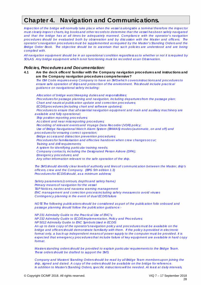
© Copyright OCIMF 2018. All rights reserved. VIQ 7 – 17 September 2018 28
Chapter 4. Navigation and Communications. Inspection of the bridge will normally take place when the vessel is alongside a terminal therefore the inspector must closely inspect charts, log books and other records to determine that the vessel has been safely navigated and that the bridge has at all times be adequately manned. Compliance with the operator’s navigation procedures should be evaluated both by observation and by discussion with the Master and officers. The operator’s navigation procedures must be supplemented as required by the Master’s Standing Orders and the Bridge Order Book. The objective should be to ascertain that such policies are understood and are being complied with. All navigation equipment should be in an operational condition regardless as to whether or not it is required by SOLAS. Any bridge equipment which is not functioning must be recorded as an Observation. Policies, Procedures and Documentation: 4.1 Are the deck officers’ familiar with the Company navigation procedures and instructions and
are the Company navigation procedures comprehensive? The ISM Code requires every Company to have an SMS which covers instructions and procedures to ensure safe operation of ships and protection of the environment. This should include practical guidance on navigational safety including:
· Allocation of bridge watchkeeping duties and responsibilities; · Procedures for passage planning and navigation, including departures from the passage plan; · Chart and nautical publication update and correction procedures; · ECDIS procedures (including chart and software updates); · Procedures to ensure that all essential navigation equipment and main and auxiliary machinery are available and fully operational; · Ship position reporting procedures; · Accident and near miss reporting procedures; · Recording of relevant events and Voyage Data Recorder (VDR) policy; · Use of Bridge Navigational Watch Alarm System (BNWAS) modes (automatic, on and off) and procedures for ensuring correct operation; · Bridge access and distraction prevention procedures; · Procedures for familiarisation and effective handover when crew changes occur; · Training and drill requirements; · A system for identifying particular training needs; · Company contacts, including the Designated Person Ashore (DPA); · Emergency procedures; and · Any other information relevant to the safe operation of the ship. The SMS should identify clear levels of authority and lines of communication between the Master, ship's officers, crew and the Company. (BPG 5th edition 1.3) Procedures for ECDIS should, as a minimum address; Safety parameters (contours, depths and safety frame) Primary means of navigation for the vessel T&P Notices, navtex and navarea warning management ENC management and correction process including safety measures to avoid viruses Contingency planning in the event of dual ECDIS failure NOTE The following publications should be considered as part of the publication folio onboard and passage planning should follow the publication guidance:- NP 231 Admiralty Guide to the Practical Use of ENC's; NP 232 Admiralty Guide to ECDIS Implementation, Policy and Procedures; NP 5012 Admiralty Guide to ENC Symbols Used in ECDIS An up to date copy of the operator's navigation policy and procedures must be available on the bridge and officers should demonstrate familiarity with them. If the policy is provided in electronic format only, a back-up independent means of power supply to the computer must be provided. It is expected that emergency procedures that include failure of key equipment are available in hard copy format. Masters standing orders should be provided to explain particular requirements to the Bridge Team. These orders should be drafted to support the SMS. Company and Masters' Standing Orders should be read by all Bridge Team members upon joining the ship, signed and dated. A copy of the orders should be available on the bridge for reference. In addition to Master's Standing Orders, specific instructions will be needed. At least at daily intervals,

© Copyright OCIMF 2018. All rights reserved. VIQ 7 – 17 September 2018 29
the Master should write in the bridge order book what is expected of the OOW for that period. These orders should be signed by each OOW when taking over a watch, to confirm that they have read, understood and will comply with the orders. Inspectors should verify the OOW understanding of these orders.
4.2 Is the vessel maintaining an adequate record of all navigational activities, both at sea and
during pilotage? All ships engaged on international voyages shall keep a record of navigational activities and incidents which are of importance to safety of navigation and which must contain sufficient detail to restore a complete record of the voyage. (SOLAS V/28). Information which should be recorded includes that concerning position, course and speed, the times and positions when passing waypoints, land or sea marks, weather and sea conditions and incidents and events including pilot embarkation/disembarkation, times of attendance and connection and disconnection of tugs, times of berthing and un-berthing, hazardous occurrences and accidents. Effectiveness of the radar(s) as measured by the performance monitor(s) should be recorded by the OOW at the end of each watch whenever the radar(s) are operational to ensure that optimal efficiency is being maintained. A numeric, percentage, graphical, or other measurement value should be recorded. Records should be maintained whether the vessel is on international voyages or not. Records may be kept either in paper format or electronic means provided such information can be readily available. Log books and engine movement (bell) books should be checked to ensure that they are up to date with entries properly made in ink and not in pencil. Empty lines are not allowed, and any correction should be such that the original entry is readable. An electronic chart display and information system (ECDIS) with GPS input (provided the equipment is in good order and the datum used in each case is the same) provides a good record of the navigational activities. Where controllable pitch propellers are fitted, the times of significant changes of pitch should be recorded if this information is not automatically logged. Software systems Meeting requirements of IMO, Marpol, SOLAS and flag states maybe an acceptable means of logbook entries replacing many of the traditional paper logs.
4.3 Are procedures in place for the testing of bridge equipment before arrival / departure and
check-lists in effective use for pre-arrival, pre-departure, watch handover and master-pilot exchange? The administration may waive the requirements to carry out the full steering gear tests for ships which regularly engage on voyages of short duration. Such ships shall carry out these checks and tests at least once a week. (SOLAS V /26.5). Periodic checks on equipment should be carried out as per the BPG checklists (B6/B7) and any defects reported to the Master. Defects should also be recorded in the log book and as appropriate identified on the Pilot Card (see Checklist A2 BPG 5th edition). The Pilot and the Master should exchange information regarding the Pilot's intentions, the ship's characteristics and operational factors as soon as practicable after the Pilot has boarded the ship. The exchange should cover.; The pilotage plan and the circumstances when deviation from the plan may be required. Any amendments to the plan should be agreed, and any changes in individual Bridge Team responsibilities made, before pilotage commences; Ship's dimensions and manoeuvring information should be provided in the form of the Wheelhouse Poster (see Checklist A3 BPG 5th edition). A manoeuvring booklet containing more detailed information should also be available on the bridge; ECDIS unit along with relevant alarm settings NP232 12.23 Information on berthing arrangements including the use, characteristics and number of tugs, mooring boats, mooring arrangements and other external facilities. All defects that might affect the manoeuvrability of the vessel or the pilotage should be reported to the Pilot. (BPG 5th edition 5.6).
4.4 Are fire and safety rounds being completed after each watch, recorded in the deck log and
are the staff conducting the rounds aware of their duties here? A lookout should not leave the bridge during the watch as this contravenes the requirements of SOLAS and STCW. Rounds of the vessel should be conducted after the end of each watch during the hours of darkness. It is recognised that in the summer months in the higher latitudes of the Northern

© Copyright OCIMF 2018. All rights reserved. VIQ 7 – 17 September 2018 30
Hemisphere that permanent daylight will occur, and it is expected that rounds of the vessel should be conducted at times when the majority of crew would be normally off duty sleeping. Rounds shall include a physical check to ensure that all loose equipment is secured, interior and exterior doors closed and there exists no immediate fire or security risks to the vessel.
4.5 Are the deck officers’ familiar with the operators Under Keel Clearance policy, able to
demonstrate satisfactory UKC calculations for the last voyage and is the policy comprehensive? The operator's policy relating to underkeel clearance should be included as part of the Master/Pilot exchange in the form of a written underkeel calculation. The policy must provide a minimum allowed under keel clearance for both coastal, river navigation, while alongside and guidance on the action to be taken in shallow water to ensure the minimum clearance is maintained. Under keel clearance can be affected by several factors and the underkeel calculations should include, but not necessarily be limited to; - The predicted height of the tide; - Changes in the predicted tidal height, which are caused by wind speed and direction and high or low barometric pressure; - Nature and stability of the bottom - i.e. sand waves, siltation etc.; - Accuracy of hydrographic data, (References to reliability is often included on charts or in the form of CATZOC on ENC's)* ; - Change of water density and the increase in draught due to fresh water allowance; - The vessel's size and handling characteristics and increase in draught due to heel; - Wave response allowance, which is the vertical displacement of the hull due to heave, roll and pitch motions; - The reliability of draft observations and calculations, including estimates of hogging and sagging; - Reduced depths over pipelines and other obstructions. *consideration of the CATZOC should be captured within the UKC calculation or policy. Once the available under keel clearance has been calculated taking into account all the applicable factors, including those above, it can then be determined whether any speed reduction is required to counter the effects of squat. Any reduction in speed should be made only after taking into account the resulting effect on manoeuvrability of the vessel especially if the passage involves passing navigational hazards at close proximity or critical course alterations in restricted waters. Squat information relevant to the vessel for both loaded and ballast passages should be readily available on the bridge. Where there is doubt that sufficient clearance can be maintained during any part of the voyage, the master must: - Inform the operator at the earliest opportunity; - If within port limits, obtain the latest sounding information, including the nature of the bottom, directly from the local authorities or terminal well before arrival. Should this not be available, the master should request guidance from the operator; - If alongside, vacate the berth if in any doubt about the risk of grounding. It should be recognised that occasionally smaller vessels 'take the ground' - i.e. sit on the bottom - at some ports. This may even be to the extent that the berth dries out completely. In such circumstances considerable reliance is placed on previous experience, as often there is no other information available to ensure that the berth is safe. In such circumstances, documentary evidence should be sought to demonstrate that the operator is aware that the vessel takes the ground at these particular ports and that the situation has been fully assessed, including the effects of stress and stability and the nature and level of the bottom. Adequate procedures should be in place for maintaining services such as firefighting and engine cooling water. Inspectors should take time to verify the UKC calculations have been correctly calculated for the critical stages of the route. Record in Comments, the operator’s policy relating to under keel clearance requirements for ocean passage, shallow water, within port limits and while alongside the berth or at SBM/CBM mooring.
4.6 Has the Bridge been adequately manned at all stages of the voyage and at anchor and were lookout arrangements adequate? Every vessel shall at all times maintain a proper look-out by sight and hearing as well as by all available means appropriate to the prevailing circumstances and conditions as to make a full appraisal of the situation and the risk of collision. (Colregs Rule 5). The look-out must be able to give his full attention to the keeping of a proper look-out and no other duties shall be undertaken or assigned which could interfere with that task. (STCW A-VIII/4-1 15)

© Copyright OCIMF 2018. All rights reserved. VIQ 7 – 17 September 2018 31
The officer in charge of the navigational watch may be the sole look-out in daylight provided that on each occasion: - The situation has been carefully assessed and it has been established without doubt that it is safe to do so - Full account has been taken of all relevant factors including but not limited to:- - State of weather - Visibility - Traffic density - Proximity of dangers to navigation; and - The attention necessary when navigating in or near traffic separation schemes - Assistance is immediately available to be summoned to the bridge when any change in the situation requires. (STCW A-VIII/4-1 16) It is of special importance that at all times the officer in charge of the navigational watch ensures that a proper look-out is maintained. In a ship with a separate chartroom the officer in charge of the navigational watch may visit the chartroom, when essential, for a short period for the necessary performance of navigational duties but shall first ensure that is safe to do so and that a proper look-out is maintained. (STCW A-VIII/4-1 32) The operator's navigational instructions and procedures must contain guidance relating to circumstances when the officer of the watch may be the sole lookout, including considerations that the OOW has had sufficient rest prior to starting the watch. The experience of the watch officers, weather and traffic conditions will dictate the required bridge manning composition at any specific time. Each stage of the voyage must be reviewed to establish that sufficient personnel were on the bridge and that an effective communications and teamwork structure was in place. Inspectors must take into account the impact of additional bridge manning upon the work load of any individual and impact of hours of rest regulations.
Navigation Equipment: 4.7 Is navigation equipment appropriate for the size of the vessel and in good order?
Note: Regardless of whether a vessel is required by legislation to carry specific navigational equipment, if equipment is fitted then it should be operational. Such equipment may be a course recorder, off-course alarm, and electronic chart display or engine order logger/printer. Random checks should be made to ensure that equipment is operational.
The following applies to all vessels constructed (i.e. keel laid) before 1st July 2002.
All ships, irrespective of size:
4.7.1 A receiver for a global navigation satellite system or terrestrial navigation radio navigation system. Or other means, suitable for use at all times throughout the intended voyage to establish and update the ship’s position by automatic means. (SOLAS V/19.2.1.6)
4.7.2 A Navtex receiver. Every ship shall be provided with a receiver capable of receiving international NAVTEX service broadcasts if the ship is engaged on voyages in any area in which an international NAVTEX service is provided. (SOLAS IV/7.1.4) Notes: The Navtex system broadcasts coastal warnings which cover the area from the fairway buoy out to about 250 miles from the transmitter, or occasionally up to 400 miles in unusual propagational conditions. Each Navtex message begins with ZCZC, followed by a space and four characters. The first, B1, identifies the station, the second, B2, the subject (i.e. navigation warning, weather forecast, gale warning, distress alert, etc.) and the third and fourth the consecutive number of the message from that station. The Navtex should be programmed to the stations for the area in which the vessel is sailing and to the type of B2 messages which are required to be received. Message types A, B and D are mandatory, but it is recommended that the receiver be programmed to receive most types.
4.7.3 A whistle, bell and gong.

© Copyright OCIMF 2018. All rights reserved. VIQ 7 – 17 September 2018 32
A whistle and bell for vessels of 12 metres or more in length and a gong for vessels of 100 metres or more in length. (Colregs D/33.a)
4.7.4 Shapes. Three balls, a cylinder and a diamond shape should be carried. (Colregs)
All ships of 150 gt and upwards:
4.7.5 A properly adjusted standard magnetic compass. A spare magnetic compass, interchangeable with the standard magnetic compass, shall be carried unless a steering compass or gyro compass is fitted. The magnetic compass shall be properly adjusted, and its table or curve of residual deviations shall be available at all times.
4.7.6 A steering magnetic compass. Unless heading information provided by the standard compass above is made available and is clearly readable by the helmsman at the main steering position. Spare magnetic compasses should be stored upside down to avoid wear of the needle bearing.
4.7.7 Means for taking bearings. As nearly as practicable over an arc of the horizon of 360o.
4.7.8 A spare magnetic compass. This should be interchangeable with the standard compass. A spare magnetic compass is not required if a steering compass or a gyro compass is fitted.
4.7.9 A telephone. Ships with emergency steering positions shall at least be provided with a telephone or other means of communication for relaying heading information.
4.7.10 A daylight signalling lamp. All ships of over 150 gt, when engaged on international voyages, shall have on board an efficient daylight signalling lamp which shall not be solely dependent on the ship’s main source of electrical power. (SOLAS 1974 V/11)
All ships of 300 gt and upwards on international voyages:
4.7.11 An automatic identification system (AIS). Ships fitted with AIS shall maintain AIS in operation at all times except where international agreements, rules or standards provide for the protection of navigational information. (SOLAS 2004 V/19.2.4.7) AIS is required to be operating while a ship is underway and while at anchor. Some port authorities may request that the AIS is kept on when a ship is alongside. The AIS operates on a VHF frequency and transmits and receives information automatically, and the output power ranges between 2 watts and 12.5 watts. Automatic polling by another station (e.g. by port authority equipment or another ship) could cause equipment to transmit at the higher (12.5 watt) level, even when it is set to low power (2 watts). When alongside a terminal or port area where hydrocarbon gases may be present, the AIS should either be switched off or the aerial isolated and the AIS given a dummy load. Isolating the aerial preserves manually input data that may be lost if the AIS was switched off. If necessary, the port authority should be informed. When alongside terminal or port areas where no hydrocarbon gases are likely to be present, and if the unit has the facility, the AIS should be switched to low power. If the AIS is switched off or isolated whilst alongside, it must be reactivated upon leaving the berth. The use of AIS equipment may affect the security of the ship or the terminal at which it is berthed. In such circumstances, the use of AIS may be determined by the port authority, depending on the security level within the port. (ISGOTT 4.8.4) Where either or both ships involved in STS operations are required to have an AIS operating while under way or at anchor, the AIS equipment should remain in use at all times including during STS operations. The AIS equipment used for the AIS broadcasts need not be set to low power output during STS operations. (STS Transfer Guide petroleum 3.5.5.4) Notes: If the AIS is not interfaced with either a radar or electronic chart display, it should be positioned adjacent to one of them. Certain manufacturers have modified their AIS equipment to provide a “Tanker Mode” that permits selection of a 1W output.
4.7.12 A VHF radio.

© Copyright OCIMF 2018. All rights reserved. VIQ 7 – 17 September 2018 33
All ships of 300 gt and upwards shall be provided with a VHF installation capable of transmitting and receiving on Channels 6, 13, 16 and 70 (DSC). It shall be possible to initiate the transmission of distress alerts on channel 70 from the position from which the ship is normally navigated.
All ships of 500 gt and upwards:
4.7.13 A gyro compass and repeaters. A gyro compass shall be fitted on ships of 500 gt and upwards constructed on or after 1st September 1984 and on ships of 1,600 gt and upwards on international voyages. Ships of 1,600 gt and upwards shall be provided with a gyro repeater or repeaters suitably placed for taking bearings as nearly as practicable over the arc of the horizon of 360o. All ships shall have a gyro-compass, or other means, to determine and display their heading by ship borne non-magnetic means, being clearly readable by the helmsman at the main steering position.
4.7.14 Visual compass readings to the emergency steering position. Arrangements shall be provided for ships constructed on or after 1st February 1992.
4.7.15 A radar installation. A radar capable of being operated in the 9 GHz (3 cm, ‘X’ band) shall be installed on ships of 500 gt and upwards constructed on or after 1st September 1984 and on ships of 1,600 gt and upwards constructed before 1st September 1984. However, ships of 10,000 gt and upwards shall be fitted with 2 radars, each being capable of being operated independently of the other and one of which must be capable of operating in the 9 GHz (3 cm, ‘X’ band).
4.7.16 Radar plotting equipment.
Facilities for plotting radar readings shall be provided on the navigation bridge of ships fitted with radars. In ships of 1,600 gt and upwards constructed after 1st September 1984 the plotting facilities shall be at least as effective as a reflection plotter.
4.7.17 An echo sounder. When engaged on international voyages, ships of 500 gt and upwards constructed on or after 25th May 1980 and ships of 1,600 gt and upwards constructed before 25th May 1980 shall be fitted with an echo sounder. Performance of the echo sounder should be tested on all ranges and scales to verify recordings against depths shown on the chart.
4.7.18 A speed and distance indicator. When engaged on international voyages ships of 500 gt and upwards constructed on or after 1st September 1984 shall be fitted with a device to indicate speed and distance.
4.7.19 Rudder angle, RPM, variable pitch and bow/stern thruster indicators. Ships of 1,600 gt and upwards constructed before 1st September 1984 and all ships of 500 gt and upwards constructed on or after 1st September 1984 shall be fitted with indicators showing the rudder angle, the rate of revolution of each propeller and in addition, where fitted with variable pitch propellers or lateral thrust propellers, the pitch and operational mode of such propellers. All these indicators shall be readable from the conning position.
All ships of 10,000 gt and upwards:
4.7.20 Radar installations. Two radar installations shall be provided, each capable of operating independently. At least one of the installations shall operate in the 9 GHz (3 cm, ‘X’ band).
4.7.21 An ARPA. Tankers of 10,000 gt and upwards shall be fitted with an automatic radar plotting aid. Vessels required to be fitted with an ARPA shall be equipped with a device to indicate speed and distance through the water. (I.e. an electromagnetic or pitot log.) If the speed through the water log is not operational, the speed of the vessel must be entered manually.
All ships of 100,000 gt and upwards:
4.7.22 A rate of turn indicator. Required for vessels of 100,000 gt and upwards constructed after 1st September 1984.
The following applies to all vessels constructed (i.e. keel laid) after 1st July 2002.(SOLAS 2004
V/19)
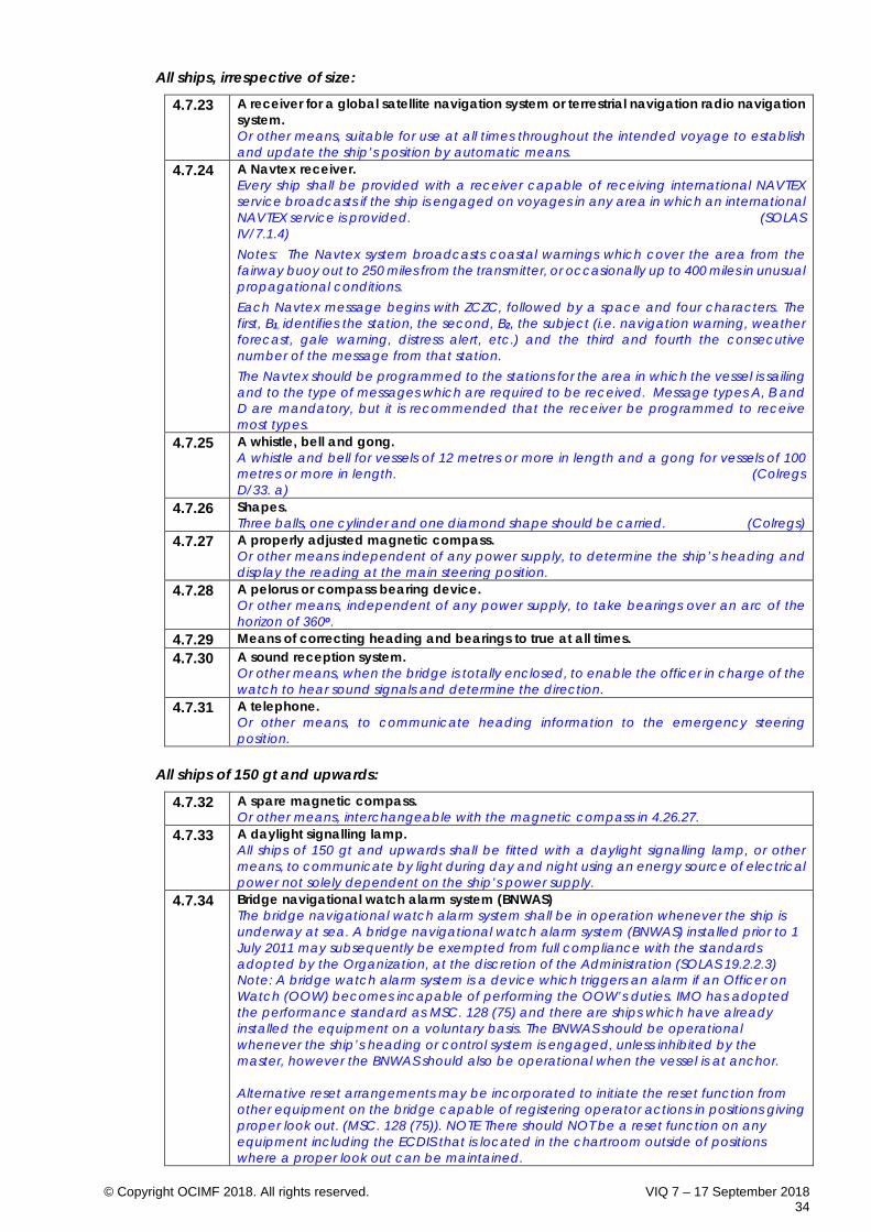
© Copyright OCIMF 2018. All rights reserved. VIQ 7 – 17 September 2018 34
All ships, irrespective of size:
4.7.23 A receiver for a global satellite navigation system or terrestrial navigation radio navigation system. Or other means, suitable for use at all times throughout the intended voyage to establish and update the ship’s position by automatic means.
4.7.24 A Navtex receiver. Every ship shall be provided with a receiver capable of receiving international NAVTEX service broadcasts if the ship is engaged on voyages in any area in which an international NAVTEX service is provided. (SOLAS IV/7.1.4) Notes: The Navtex system broadcasts coastal warnings which cover the area from the fairway buoy out to 250 miles from the transmitter, or occasionally up to 400 miles in unusual propagational conditions. Each Navtex message begins with ZCZC, followed by a space and four characters. The first, B1, identifies the station, the second, B2, the subject (i.e. navigation warning, weather forecast, gale warning, distress alert, etc.) and the third and fourth the consecutive number of the message from that station. The Navtex should be programmed to the stations for the area in which the vessel is sailing and to the type of messages which are required to be received. Message types A, B and D are mandatory, but it is recommended that the receiver be programmed to receive most types.
4.7.25 A whistle, bell and gong. A whistle and bell for vessels of 12 metres or more in length and a gong for vessels of 100 metres or more in length. (Colregs D/33. a)
4.7.26 Shapes. Three balls, one cylinder and one diamond shape should be carried. (Colregs)
4.7.27 A properly adjusted magnetic compass. Or other means independent of any power supply, to determine the ship’s heading and display the reading at the main steering position.
4.7.28 A pelorus or compass bearing device. Or other means, independent of any power supply, to take bearings over an arc of the horizon of 360o.
4.7.29 Means of correcting heading and bearings to true at all times. 4.7.30 A sound reception system.
Or other means, when the bridge is totally enclosed, to enable the officer in charge of the watch to hear sound signals and determine the direction.
4.7.31 A telephone. Or other means, to communicate heading information to the emergency steering position.
All ships of 150 gt and upwards:
4.7.32 A spare magnetic compass. Or other means, interchangeable with the magnetic compass in 4.26.27.
4.7.33 A daylight signalling lamp. All ships of 150 gt and upwards shall be fitted with a daylight signalling lamp, or other means, to communicate by light during day and night using an energy source of electrical power not solely dependent on the ship’s power supply.
4.7.34 Bridge navigational watch alarm system (BNWAS) The bridge navigational watch alarm system shall be in operation whenever the ship is underway at sea. A bridge navigational watch alarm system (BNWAS) installed prior to 1 July 2011 may subsequently be exempted from full compliance with the standards adopted by the Organization, at the discretion of the Administration (SOLAS 19.2.2.3) Note: A bridge watch alarm system is a device which triggers an alarm if an Officer on Watch (OOW) becomes incapable of performing the OOW’s duties. IMO has adopted the performance standard as MSC. 128 (75) and there are ships which have already installed the equipment on a voluntary basis. The BNWAS should be operational whenever the ship’s heading or control system is engaged, unless inhibited by the master, however the BNWAS should also be operational when the vessel is at anchor. Alternative reset arrangements may be incorporated to initiate the reset function from other equipment on the bridge capable of registering operator actions in positions giving proper look out. (MSC. 128 (75)). NOTE There should NOT be a reset function on any equipment including the ECDIS that is located in the chartroom outside of positions where a proper look out can be maintained.

© Copyright OCIMF 2018. All rights reserved. VIQ 7 – 17 September 2018 35
With respect to testing of the equipment, the inspector may ask for the mains power supply for the BNWAS to be simulated to fail to establish whether the equipment is still operational, and alarms generated on main power failure. There is NO requirement to ‘trip’ the backup battery supply and this should not be requested.
All ships of 300 gt and upwards:
4.7.35 An echo sounding device. 4.7.36 A 9 GHz (3 cm ‘X’ band) radar. 4.7.37 An electronic plotting aid.
To plot electronically the range and bearing of targets to determine collision risk. 4.7.38 A speed and distance measuring device.
To indicate speed and distance through the water. If the device is not operational, speed input to the ARPA, where fitted, must be manual.
4.7.39 A properly adjusted transmitting heading device. Or other means, to transmit heading information for input into the 9 GHz radar, the plotting aid and the speed and distance-measuring device.
4.7.40 A VHF radio. All ships of 300 gt and upwards shall be provided with a VHF installation capable of transmitting and receiving on Channels 6, 13, 16 and 70 (DSC). It shall be possible to initiate the transmission of distress alerts on channel 70 from the position from which the ship is normally navigated.
All ships of 300 gt and upwards on international voyages:
4.7.41 An automatic identification system (AIS). Ships fitted with AIS shall maintain AIS in operation at all times except where international agreements, rules or standards provide for the protection of navigational information. (SOLAS V/19.2.4.7) Notes: If the AIS is not interfaced with either a radar or electronic chart display, it should be positioned adjacent to one of them. See guidance to Q4.26.11.
All ships of 500 gt and over:
4.7.42 A gyro compass. Or other means, to determine and display the heading by ship borne non-magnetic means.
4.7.43 A gyro compass heading repeater. To supply heading information at the emergency steering position, if provided.
4.7.44 A gyro compass bearing repeater. To take bearings over an arc of the horizon of 360o.
4.7.45 Rudder, propeller, thrust, pitch and operational mode indicators. All to be readable from the conning position.
4.7.46 An automatic tracking aid. To plot automatically the range and bearing of other targets to determine collision risk.

© Copyright OCIMF 2018. All rights reserved. VIQ 7 – 17 September 2018 36
All ships of 3,000 gt and upwards:
4.7.47 A 3 GHz (10 cm, ‘S’ band) radar. Or a second 9 GHz (3 cm, ‘X’ band) radar where considered appropriate by the administration.
4.7.48 A second automatic tracking aid. Functionally independent of the first automatic aid.
4.7.49 A voyage data recorder. (VDR) VDR's shall be subjected to an annual performance test. The test shall be conducted by an approved testing or servicing facility. A copy of the certificate of compliance issued by the testing facility, stating the date of compliance and the applicable performance standards, shall be retained on board the ship (SOLAS V/18.8).
To assist in casualty investigations, cargo ships, when engaged on international voyages, shall be fitted with a VDR which may be a simplified voyage data recorder (S-VDR) as follows: .1 in the case of cargo ships of 20,000 gross tonnage and upwards constructed before 1 July 2002, at the first scheduled dry-docking after 1 July 2006 but not later than 1 July 2009; .2 in the case of cargo ships of 3,000 gross tonnage and upwards but less than 20,000 gross tonnage constructed before 1 July 2002, at the first scheduled dry-docking after 1 July 2007 but not later than 1 July 2010; .3 Administrations may exempt cargo ships from the application of the requirements of subparagraphs .1 and .2 when such ships will be taken permanently out of service within two years after the implementation date specified in subparagraphs .1 and .2 above.
(SOLAS V Reg 20.1.) 4.7.50 Electronic Chart Display and Information System (ECDIS)
Tankers of 3,000 GRT and upwards engaged on international voyages shall be fitted with at least one Electronic Chart Display and Information System (ECDIS). ECDIS must be “type approved” in accordance with IMO Res A.817 (19) as amended and use only official Electronic Navigation Charts (ENCs). A secondary means of navigation must also be provided. The secondary means may comprise: -
• A second “type approved” ECDIS with ENC’s and voyage plan loaded before commencement of the voyage and must be operational at all times when the ship is in coastal waters, or,
• A full folio of paper charts that satisfies SOLAS carriage requirements, corrected to the latest available Notices to Mariners, covering the intended voyage and showing the intended voyage plan.
All ships of 10,000 gt and upwards:
4.7.51 An ARPA, equipped with speed through the water input. An ARPA, or other means, to plot automatically the range and bearing of at least 20 other targets, connected to a device to indicate speed and distance through the water, to determine collision risks and simulate a trial manoeuvre.
4.7.52 A heading or track control system. To automatically control and keep to a heading and/or straight track.
All ships of 50,000 gt and upwards:
4.7.53 A rate of turn indicator. Or other means to determine and display the rate of turn.
4.7.54 A speed and distance measuring device. From 1st July 2002 new ships are to be equipped with a device to indicate speed and distance over the ground in the forward and athwartships direction.
4.8 Are navigation lights in good order, the OOW aware of the procedures for testing the lights
and actions in event of failure? Primary and secondary systems should be in good order, and there should be a procedure to check the navigation light failure alarm.
4.9 Are the Standard Magnetic and Gyro compasses in good order and is the OOW aware of the
requirements for taking compass errors and is the compass error book maintained. The magnetic compass must be in good working order and the ship's heading clearly displayed at the main steering position. The binnacle lights must be operational. The compass must be provided with an azimuth mirror or other means to take bearings. The compass shall be adjusted if a period of two years
© Copyright OCIMF 2018. All rights reserved. VIQ 7 – 17 September 2018 37
has elapsed since the last adjustment and a record of compass deviations has not been maintained, or the recorded deviations are excessive or when the compass shows physical defects. Masters and Officers should be aware that portable electrical equipment (e.g. radios and tape recorders) or items made of steel can affect the performance of a compass and must ensure that such items are kept away from the compass position. A compass deviation card should be prepared each time the compass is adjusted. Separate deviation cards should be prepared for the standard compass and the transmitting magnetic compass repeater, if fitted (Not required for TMC if attached to the Magnetic Compass). The gyro compass (or compasses) should be checked to ensure that the speed and latitude corrections are properly applied. Gyro maintenance records should be reviewed to confirm that the gyro(s) are operating satisfactorily. This can be done either manually or by automatic input from GPS/Logs. Each of the gyro repeaters, including those that may be fitted in the emergency steering position and the engine control room must be synchronised. Where two gyros are fitted, a change-over device must be fitted, and change-over procedures must be posted. Magnetic and gyro compass errors should be checked and recorded each watch, where possible, using either azimuth or transit bearings. A deviation card for the magnetic compass should be maintained and be available to the Bridge Team. (5th edition BPG 4.3.4) The error of the gyro should be determined by external observations - celestial bearings, transits etc. and the gyro and magnetic compass headings then compared to determine the magnetic compass error. Where a gyro repeater is used to take a bearing, an accurate comparison between the repeater and the master gyro should be made. When compass errors cannot be taken it is not necessary to state this in the compass error book. The previous record completed by a qualified compass adjuster should be retained to prove that adjustment has not been required in the intervening period. A comparison between the magnetic and gyro headings should be made at each substantial course alteration and once each watch. Details must be recorded in the Deck Log Book. Some Administrations require compass errors to be recorded in the Deck Log Book rather than a separate Compass Error Book. The Magnetic compass errors recorded in the compass error book should broadly agree with the deviation card. The Magnetic compass deviation may be excessive at the time of inspection due to the presence of external metal structures such as loading arms, gangway towers etc.
4.10 Was the hand steering in use for the vessels transit from pilotage to the berth as appropriate and are deck officer’s familiar with the changeover from hand steering to auto and vice versa? Times and locations of engaging hand steering should be recorded in the deck log book or bell book (electronic means of recording are also acceptable).
4.11 Are the Deck Officers familiar with procedures to retain the VDR data in the event of an
incident? In the event of an incident the data retained in the VDR can be invaluable in accident investigations, ship's crew should be aware of how to retain this data and prevent it from being over written. The OCIMF information paper "Recommendations on the Proactive Use of Voyage Data Recorder Information" provides further information on the use of VDRs. The current performance specification for VDR's only requires that the data is stored for a minimum of 12 hours before being overwritten. Since many existing VDR's simply meet the required 12 hours, if no action is taken to preserve the recorded VDR data within 12 hours of the start of an incident, the data will be lost or overwritten, thereby negating the purpose of having a VDR installed.
4.12 Is there an effective Chart and Publication (Paper and Electronic) Management System in
place and are the deck officer’s familiar with the process including the effective management of T and P notices? A management system should record the charts, publications and licences/permits carried, and also when the charts and other publications were last corrected. (5th edition BPG 4.12.1) Charts should be in good condition. The paper surface should be intact, and charts should be replaced when torn, not taped together. Procedures should be checked to ensure that the ordering and supply of charts, publications and corrections are sent to the vessel in a timely manner. Many vessels receive the 'Notice to Mariners' by electronic means. Publications in electronic format may be accepted by certain flag Administrations and should be indicated where approved in lieu of paper publications on SEC Form E including backup arrangement.

© Copyright OCIMF 2018. All rights reserved. VIQ 7 – 17 September 2018 38
'Block' corrections to navigational charts must be in the same colour scheme as the original chart. 'Block' corrections to ALRS, Tide Tables, and Sailing Directions etc. can be in 'Black and White' even if the original is in colour. Such a system must include an adequate, up to date filing system for Temporary and Preliminary Notices, Navarea and Navtex warnings. Relevant warnings must be charted and the chart they have been entered on must be recorded on the warning notice in order that the warning can be removed when the notice is cancelled. One shortcoming of ECDIS is that it does not very effectively draw attention to temporary and preliminary (T&P) updates within ENCs. It is also a fact that not all Hydrographic Offices include T&P information in their ENCs. The UKHO has also recognised that the lack of consistent, worldwide, T&P information is a significant problem for mariners and, as an interim measure, is including all Admiralty T&P NMs in its ‘Admiralty Information Overlay’. This allows the limits of the T&P NMs to be displayed as an overlay to ENCs in the Admiralty Vector Chart Service (AVCS) by compatible display systems. Other ECDIS manufacturers and ENC suppliers may have their own similar system. Inspectors should verify the system installed to ensure relevant notices are effectively managed.
4.13 Are deck officers aware of the requirements for managing Navtex and Navarea Warnings
and is there evidence of an effective system in place to monitor these warnings? A system should be in place for monitoring navigational warnings appropriate to the ship's trading area and for ensuring relevant navigational warnings are brought to the attention of the watchkeeping officers. Navtex warnings should be monitored by the officer on watch at the time of receipt. He should ensure that the system is maintained by initialling the warnings received to show that they have been checked as to whether they are relevant to the current voyage. Those which are relevant should be charted. Some ECDIS systems permit Navtex messages to be automatically input onto the ECDIS and displayed automatically. Inspectors should establish the procedure onboard each vessel to ensure relevant messages are captured on the ENC's as an overlay either automatically or by manual input. Where manual input to the ECDIS is necessary, there should be an effective means in place to remove expired messages. The navtex and ECDIS should be checked to ensure that the correct station(s) and message type(s) are entered. Navigation warnings maybe received through EGC, navtex messages or the weekly NTM's. Warnings received through other means such as Chartco should be verified with the official source data. The availability of Navigational Warnings on the web does not relieve Masters / Captains of the requirement to receive Navigational Warnings via IMO/IHO approved broadcast systems, as websites are not continuously updated and not necessarily monitored for correctness. (IHO)
4.14 Are Master and deck officer’s familiar with the operation of the ECDIS system fitted on board?
The Master and deck officers should be familiar with the operation of the ECDIS. Master and deck officers should be able to demonstrate the operation of the ECDIS including, but not limited to: -
• Creating and uploading passage plans • Recalling previous voyages • Route checking and management of alarms • Plotting manual fixes (visual bearing and radar range) • Creating parallel index lines • Setting safety depths and safety contours as appropriate to the draught of the vessel • Setting of Safety frame/safety cone • Ensuring system is updated to the latest corrections. • AIS and or Radar overlay if fitted • Understanding of limitations of operating in RCDS mode • Knowledge of SCAMIN and how it is displayed • Knowledge of CATZOCs • Familiarity of deck officers with contingency action in case of ECDIS failure.
The above list is not exhaustive and the inspector can ask other features to be demonstrated in order assess knowledge of the system. Further guidance to the operation of ECDIS can be found in MSC.1/Circ 1503 “ECDIS – Guidance for Good Practice”. The ECDIS must be updated to the latest version of the International Hydrographic Organisation (IHO) standards, the list of current standards is maintained on the IHO web site www.iho.int . Changes to the

© Copyright OCIMF 2018. All rights reserved. VIQ 7 – 17 September 2018 39
IHO S-52 Presentation Library introduced in edition 4.0 which is mandatory on all ECDIS from 01 Sep 2017. The IHO may make further changes as necessary. If no ECDIS system is fitted on board, answer the question ‘NA’. If only one ECDIS fitted and paper charts are also provided record which is the primary source of navigation and which is the backup.
4.15 Is the master and deck officers’ familiar with the safety parameter settings for the ECDIS and have the safety settings been correctly applied for the vessels passage? Safety parameters should be well understood, clearly defined within the Company SMS and correctly applied, with due consideration for the vessels position, charted depth and surrounding navigable waters/ hazards. Hence, during the voyage there are likely to be several changes to the safety parameters that must be clearly identified in the passage plan. The value of the safety contour should be calculated during the planning phase and entered by the OOW. The Safety Contour marks the division between "safe‟ and "unsafe‟ water. When the safety contour is not displayed to the specified value set by the navigator, then the safety contour is shown to the next deepest contour as per the default layers in the electronic charts. During route planning, an indication will be made if the route is planned to cross the ship’s safety contour. At the time of route monitoring, ECDIS should give an alarm if, within a specified time set by the navigator, own ship is likely to cross the safety contour. The Safety Depth highlights individual soundings in bold that would appear where the sounding is less than the level set on the safety depth alarm. This is generally set the same as the safety contour. Safety Frame or Safety Cone is equally as important as the Safety Contour, as this will provide early indication of the vessel running into danger or approaching an area of concern. Equally, if the safety frame is set too large then the ECDIS is likely to provide alarm overload with the result that an essential alarm may possibly be ignored.
4.16 Were the charts used for the previous voyage appropriate? Note: The largest scale charts published, where appropriate, should be used. The master should have made every effort to obtain the necessary charts if the vessel is ordered to a port not covered by the chart folio system.
4.17 Are the master and deck officers aware of the requirements of Electronic Chart Display and Information System (ECDIS) and does the system fitted meet SOLAS and flag state requirements? ECDIS must be “type approved” in accordance with IMO Res A.817 (19) as amended and use only official Electronic Navigation Charts (ENCs). For vessels greater than 3000gt a secondary means of navigation must also be provided. The secondary means may comprise: • A second “type approved” ECDIS with ENC’s and voyage plan loaded before commencement of the voyage and must be operational at all times when the ship is in coastal waters, or • A full folio of paper charts that satisfies SOLAS carriage requirements, corrected to the latest available Notices to Mariners, covering the intended voyage and showing the intended voyage plan. Record of Equipment for Cargo Ship Safety (Form E) attached to the Cargo Ship Safety Equipment Certificate will state if ECDIS is fitted and the method of back-up (either another ECDIS or paper charts). The ‘Record of Approved Cargo Ship Safety Equipment’ will provide additional information of systems provided and should be maintained up to date. (MSC.1/Circ.1496) The Company SMS must clearly state what is the primary means of navigation regardless of Safety Equipment Certificate Form E (or Safety Certificate Form C) Frequent checks should be made of the ECDIS position fixing system (normally GPS) by the use of other means. Such checks should include: - Parallel indexing and use of clearing bearings; - Use of radar to check the accuracy of the charted position by comparing the location of the radar target against the charted symbol, including the use of radar overlay if fitted. - Visual cross bearings; ECDIS should store and be able to reproduce certain minimum elements required to reconstruct the navigation and verify the official database used during the previous 12 hours. The following data shall be recorded at one-minute intervals: .1 to ensure a record of own ship's past track: time, position, heading, and speed; and .2 to ensure a record of official data used: ENC source, edition, date, cell and update history. In addition, ECDIS should record the complete track for the entire voyage, with time marks at intervals

© Copyright OCIMF 2018. All rights reserved. VIQ 7 – 17 September 2018 40
not exceeding 4 hours. ECDIS should be connected to systems providing continuous position-fixing, heading and speed information. (Res A.817(19)12.2) As long as the ECDIS meets the minimum performance standard, then observations should NOT be made even if the ECDIS cannot perform other features that maybe be additional to some ECDIS e.g. radar overlay, navtex connection etc. Changes to the IHO S-52 Presentation Library introduced in edition 4.0 which is mandatory on all ECDIS from 01 Sep 2017 invalidated the previous test required in IHO ECDIS Data Presentation and Performance Checks which were specifically designed and developed for ECDIS using the IHO S-52 Presentation Library edition 3.4 or earlier.
The ECDIS must be updated to the latest version of the International Hydrographic Organisation (IHO) standards, the list of current standards is maintained on the IHO web site www.iho.int .
4.18 Has the vessel been safely navigated in compliance with international regulations and are deck officers’ familiar with these requirements? A ship shall use a mandatory ships' routeing system adopted by the Organization as required for its category or cargo carried and in accordance with the relevant provisions in force unless there are compelling reasons not to use a particular ships' routeing system. Any such reason shall be recorded in the ships' log. (SOLAS V/Reg 10.7). Charts of at least the previous voyage should be checked to determine that the vessel has been safely navigated, including maintenance of a safe distance off the coast particularly in bad weather, correct use of traffic separation zones, intervals between position fixes, correct reporting, avoidance of prohibited areas and dangerous wrecks and adherence to printed notes on the charts, etc.
4.19 Is the master and deck officers aware of the requirements for the echo sounder and is there evidence that it has been in use as appropriate during the voyage? The echo sounder should always be used when making a landfall and kept switched on in coastal and pilotage waters. If the echo sounder is fitted with a shallow water alarm, the alarm should be set to an appropriate safe depth to warn of approaching shallow water. (5th edition BPG 4.5) The date and time of switching on should be marked on the recorder chart where provided. In addition, the date and time of passing significant land or seamarks should be marked on the recorder. Many modern electronic echo sounders have an in-built 24-hour memory which can be recalled in lieu of paper trace. If an electronic memory is not provided, the echo sounder should be provided with a printed record. It is acceptable evidence for the echo sounder history to be noted from the ECDIS data. Where an electronic display history is provided to record trending and a VDR to record times, a 'Y' response should be made, together with a short explanation in Comments.
4.20 Was a comprehensive berth to berth passage plan available for the previous voyage and
were the deck officers aware of position fixing requirements including the use of parallel indexing both at sea and during pilotage?
Prior to proceeding to sea, the Master shall ensure that the intended voyage has been planned using appropriate charts and publications for the area concerned.(SOLAS V/34 and IMO Res. A.893) Notes: The passage plan should be completed by the navigating officer and verified and approved by the Master. It should be comprehensive, contain full details of the voyage and be easy to interpret. Passage planning should follow the publication guidance; NP 231 Admiralty Guide to the Practical Use of ENC's; NP 232 Admiralty Guide to ECDIS Implementation, Policy and Procedures; The passage plan should be written on each applicable chart, which may be supported by a conning notebook, or equivalent. Excessive information in the navigational areas of a chart must be avoided by recording the information away from the track and drawing attention to it by a line or reference letter. The following should be marked on the chart, where it enhances safe navigation:
• Parallel indexing (not from floating objects unless they have been first checked for position); • Chart changes; • Methods and frequency of position fixing and/or position verification; • Prominent navigation and radar marks; • No-go areas (the excessive marking of no-go areas should be discouraged – see below); • Landfall targets and lights; • Clearing lines and bearings; • Transits, heading marks and leading lines; • Significant tides or current; • Safe speed and necessary speed alterations;

© Copyright OCIMF 2018. All rights reserved. VIQ 7 – 17 September 2018 41
• Changes in machinery status; • Minimum under keel clearance; • Positions where the echo sounder should be activated; • Crossing and high-density traffic areas; • Safe distance off; • Anchor clearance; • Contingency plans; • Abort positions; • VTS and reporting points, etc. • Air draft when passing under bridges/power lines/cable cars etc.
In the event that ECDIS is the primary means of navigation, the above should be taken into account. Charted passage planning information should not obscure printed details, nor should the information on charts be obliterated by the use of highlight or felt-tip pen, red pencil, etc. No-go areas should be highlighted but should be reserved for those areas where the attention of the navigator needs to be drawn to a danger such as shallow water or a wreck close to the course line. Extensive use of no-go areas should be discouraged. No-go areas vary with change of draft and tide and will therefore also vary with the time of passage. They should not therefore be permanently marked. All courses previous to the last voyage should have been erased. Course lines must not be marked in ink, although it is acceptable to plot alter course positions in ink where these are frequently in use. If the vessel is ECDIS compliant and has one ECDIS and paper charts, either is designated as the primary means of navigation and the other the back up. If the back-up is ECDIS it must be loaded with relevant official charts and the voyage plan before commencement of the voyage. Similarly, if paper charts are being used as the back-up, they must be readily available, and the voyage plan must be indicated on the charts. The back-up arrangement must be ready for immediate use, particularly when in confined waters.
Communications. 4.21 Are deck officers’ familiar with the preparation and transmission of distress and urgency
messages on the GMDSS equipment, are instructions clearly displayed and equipment in good order? The OOW should be familiar with the procedures for sending distress, urgency and safety messages contained in the International Aeronautical and Maritime Search and Rescue Manual Volume III (IAMSAR Vol III), Section 4. Particular care should be taken to ensure that alerts and messages sent by DSC, radio-telephony and satellite communications are given an appropriate priority. (3.15.2 BPG 5th edition) The minimum requirements for radio equipment for the vessel should be taken from the Radio Certificate and its attachment Form R or in Form C if the Safety Radio Certificate is combined in the Harmonised Certificate. If the vessel uses EX rated mobile phones within the gas-hazardous area confirm that proper certification is provided.
4.22 Are officers aware of the function of the ship security alert system and how it operates?
Under no circumstances should enquiries be made as to the system details. All ships constructed after 1st July 2004 shall be fitted with a ship security alert system. (SOLAS XI-2/6.1.1) The ship security alert system shall, when activated, initiate and transmit a ship-to-shore security alert to a competent authority, which in these circumstances may include the Company, identifying the ship, its location and indicating that the security of the ship is under threat or it has been compromised. (SOLAS XI-2/6.2.1) It shall not send the security alert to other ships or raise the alarm on board and it shall continue until deactivated or reset. (SOLAS XI-2/6.2.2,3 and 4). The ship security alert system shall be capable of being activated from the navigation bridge and in at least one other location. (SOLAS XI-2/6.3.1) SIRE defines Company as the vessel Operator.
4.23 Are the officers aware of the periodical test requirements for GMDSS equipment and is the
radio logbook correctly maintained with entries of such tests? The following tests should be carried out: Daily · Function of DSC facilities (VHF, MF and HF) using built-in test functions · Battery supplies to GMDSS equipment including charging condition and battery voltage checks. Weekly

© Copyright OCIMF 2018. All rights reserved. VIQ 7 – 17 September 2018 42
· Function of DSC facilities by way of a test call with a coastal station (if in range or at the earliest opportunity if out of range) · Reserve power supplies to GMDSS equipment other than batteries (e.g. emergency generator) Monthly · Enhanced group calling (EGC) function · EPIRB function (using built-in test) and condition · SART function (using built-in test) and condition · Condition and security of batteries · Condition of aerials and insulators · Function test of survival craft two-way VHF equipment (BPG 5th Edition 3.15.6) Where a reserve source of energy consists of rechargeable accumulator batteries, their capacity shall be checked, using an appropriate method, at intervals not exceeding 12 months, when the ship is not at sea. (SOLAS IV/13.6) A GMDSS radio log should be kept in order to provide a record of all events connected with the radio communications facilities on board. As a minimum the following should be recorded: · A summary of communications relating to distress, urgency and safety. This includes any periods when a radio watch is discontinued and the reasons for doing so; · The position of the ship at least daily; · The identities of other stations with which the ship communicates or attempts to communicate; · Records of any difficulties experienced with communications; · Incidents involving unnecessary or inappropriate transmissions with the identities of the stations concerned, if known; and · Cancellation of any false alerts. The requirements relating to the retention of radio logs are determined by the flag State and the ITU Radio Regulations and should be included in the SMS. (BPG 5th Edition 3.15.5)
4.24 Is there a maintenance programme in place to ensure availability of the radio equipment?
On ships engaged on voyages in sea areas A1 and A2, the radio availability shall be ensured by using such methods as: - Duplication of equipment; or - Shore based maintenance (the requirement on GMDSS vessels to have shore based maintenance does not infer there should necessarily be a contract but that maintenance should be carried out annually by a shore-based i.e. 'expert' organisation); or - At-sea electronic maintenance capability; or - A combination of these as may be approved by the Administration. (SOLAS IV/15.6) On ships engaged on voyages in sea areas A3 and A4, the radio availability shall be ensured by using a combination of at least two of the methods detailed above. (SOLAS IV/15.7).
4.25 Is the satellite EPIRB fitted, armed, labelled correctly and inspected in accordance with the manufacturer's requirements? The EPIRB shall be: - capable of transmitting a distress alert through the polar orbiting satellite service operating in the 406 MHz band;'' - Installed in an easily accessible position; - Ready to be manually released and capable of being carried by one person into a survival craft; - Capable of floating free if the ship sinks and of being automatically activated when afloat; and - Capable of being activated manually. (SOLAS IV/7.1.6) Satellite EPIRBs shall be annually tested within 3 months before the expiry date, or 3 months before or after the anniversary date, of the Cargo Ship Safety Radio Certificate. The test may be conducted on board the ship or at an approved testing station; and subject to maintenance at intervals not exceeding five years. (SOLAS IV/15.9) The vessel's name, the serial number and the maritime mobile services identity (MMSI or 15 Hex ID) should be clearly indicated on the EPIRB. The inspection of EPIRB's should include: - Inspection of the housing to ensure it is undamaged; - Inspection of the hydrostatic release unit to ensure it is in good order and in date. Releases should be renewed after two years; - Inspection of the lanyard, which should be neatly stowed and not attached to the ship; - Ensuring that the markings remain clearly decipherable; - Checking the battery to ensure it is in good order and in date. The battery life for most EPIRB's is 5 years; - Carrying out a self-test. Most EPIRB's have a self-test facility which is usually a spring-loaded switch. When activated a light will indicate that the test circuits are operating correctly and sometimes this will also activate the strobe light. It is recommended that the self-test switch be held for no more than 2

© Copyright OCIMF 2018. All rights reserved. VIQ 7 – 17 September 2018 43
flashes of the strobe light, or no longer than 1 minute after the first self-test mode burst transmission. When the self-test is activated on a 406 MHz EPIRB, the EPIRB is allowed to radiate a single burst which is specially coded so that it is ignored by the COSPAS-SARSAT system. The EPIRB must never be tested by actual operation. The annual testing of 406 MHz satellite EPIRB's required by SOLAS IV/15.9 requires test equipment capable of performing all the relevant measurements detailed in MSC/Circ 1040.
4.26 Is the vessel equipped with sufficient intrinsically safe portable radios for use on deck? Sufficient portable radios should be available to allow communications between the cargo control, the deck officer, the deck watch and the master, as well as the pumpman if required.
4.27 Are survival craft portable VHF radios and Search and Rescue Locating Devices in good order and charged? At least 3 two-way VHF radiotelephone apparatus shall be provided on every cargo ship of 500 gross tonnage and upwards. (SOLAS III/6.2.1.1) The two-way radiotelephone should be capable of operation on the frequency 156.800 MHz (VHF channel 16) and on at least one additional channel. (Res. A.809/3.1) The battery for equipment with a user -replaceable energy source or radio with a non-replaceable energy source shall have a non-replaceable seal to show the unit has not been activated. (Res. A.809/12.2 and 12.3) Primary battery shelf life must be at least 2 years and highly visible yellow/orange colour or marked with a surrounding yellow/orange marking strip. There is no requirement for the two-way VHF radios to be Ex rated or intrinsically safe type, though if the units are being used for shipboard operations then there must be effective measures in place to prevent them being used in the gas hazardous area. For radios installed on or after 1st July 2005 revised performance standards for survival craft portable two-way VHF radiotelephone apparatus applies (Res MSC.149(77)) At least one radar transponder shall be carried on each side of every cargo ship of 500 gross tonnage and upwards. The radar transponders shall be stowed in such locations that they can be rapidly placed in any survival craft (other than the forward liferaft). On ships equipped with free-fall lifeboats, one of the transponders shall be stowed in the free-fall lifeboat and the other located in the immediate vicinity of the navigation bridge so that it can be utilised on board and ready to transfer to any other survival craft. (SOLAS III/6.2.2).
Additional comments: If the Inspector has comments in respect of the subject matter covered by the Chapter additional to those which the Inspector may make in response to the specific questions in the Chapter, the Inspector should include such additional comments in this section.

© Copyright OCIMF 2018. All rights reserved. VIQ 7 – 17 September 2018 44
Chapter 5. Safety Management 5.1 Are officers’ familiar with the process for conducting Risk Assessments for routine and non-
routine tasks, do operators provide adequate procedures for conducting RA and is there sufficient evidence of this process undertaken? The risk assessment process identifies hazards present in a work undertaking, analyses the level of risk, considers those in danger and evaluates whether hazards are adequately controlled, taking into account any measures already in place. Two distinct types of Task Based Risk Assessment may be used. First, a range of vessel-specific generic TBRAs that can be used for all routine and low-risk tasks can be developed. These should be periodically reviewed, but frequency would very much depend on the particular circumstances on the vessel and the level of risk. The second type of TBRA would be used for specific high-risk jobs that are not routine, such as working aloft or enclosed space entry. These should relate to the specific persons who will be involved in the work and valid only for the duration of that job. In both cases, the assessments should be carried out by a competent person or persons who understand the work being assessed. It is also preferable that seafarers who will be involved in the work should also be involved in the assessment process. A toolbox talk is another form of risk assessment carried out in support of a TBRA. Its prime purpose is to talk through the procedures of the job in hand and the findings of the TBRA with the seafarers involved. (COSWP 1.2.5)
5.2 Is there evidence of a permit to work system in place for hazardous activities, are the crew aware of these requirements and is there documented evidence of compliance? The safety management system for individual ships will determine when permit to work systems should be used, and the form of the permit to work. (COSWP 14.2.3) Permits to work would normally be required for the following categories of work: - entry into dangerous (enclosed) space; - gas testing/equipment; - hot work; - working at height/over the side; - general electrical (under 1000 volts); - electrical high voltage (over 1000 volts); - working on deck during adverse weather; and - lifts, lift trunks and machinery. This list is not exhaustive. Permits to work, following a similar format, may be required and developed for other categories of work. (COSWP Annex 14.1)
5.3 Is the appointed Safety Officer suitably trained, aware of his responsibilities and is there
evidence to show that the safety officer has been effectively performing duties associated with this role? One of the primary functions of the safety officer, who preferably should be an experienced seafarer, is to inspect all areas of the vessel on a regular basis for safety compliance and to report any deficiencies noted. The purpose is to raise awareness, prevent accidents and to identify regular occurrences that might require the operator's intervention on a fleet-wide basis. The function of the safety officer may not involve equipment maintenance, although it does include identifying equipment deficiencies. Evidence that the Safety Officer has undertaken an appropriate Safety Officer training course should be provided. Training records must match the job description for the Safety Officer within the Safety Management System. Some training may be provided on board, but the safety officer should have attended a suitable safety officer’s training course. Suitable safety officer training should cover the following topics: - The tasks of the safety committee. - The rights and roles of members of the safety committee. - How to carry out risk assessment and management. - How to provide the necessary advice to resolve safety concerns or problems and to encourage adherence to prevention principles. - Supervision of safety tasks assigned to crew and other seafarers on board, and passengers where applicable. - Accident and incident investigation, analysis and making appropriate corrective and preventative recommendations to prevent their recurrence. - How to obtain relevant information on a safe and healthy working environment from the competent
© Copyright OCIMF 2018. All rights reserved. VIQ 7 – 17 September 2018 45
authority and the Company. - Effective means of communication with a multinational crew. - The commitment required to promote a safe working environment on board. The safety officer should be familiar with the principles and practice of risk assessment, and should be available to advise those preparing and reviewing risk assessments. (COSWP 13.3.2.2) The safety officer’s role should be a positive one, seeking to initiate or develop safety measures before an incident occurs rather than afterwards. (COSWP 13.4.2.2)
5.4 Are the ship's officers able to demonstrate their familiarisation with the operation of fixed and
portable firefighting, lifesaving and other emergency equipment? Ship's officers should be familiar with the operation of: - fixed firefighting systems (foam, CO2, dry powder etc) - main and emergency fire pumps - emergency steering gear - donning and use of breathing apparatus and oxygen resuscitation equipment
5.5 Are the crew aware of the requirements for wearing personal protective equipment such as
boiler suits, safety footwear, eye and ear protection, safety harnesses, respiratory and chemical protective equipment? Documented guidance relating to the use of PPE should be provided and the crew should be familiar with those requirements or where to refer to the requirements. SMS often provide a matrix of PPE requirements for simplicity posted in various public areas on the vessel. If there is no such matrix then inspectors should ascertain there is adequate guidance provided.
5.6 Is all electronic equipment in use in gas hazardous areas intrinsically safe?
Only torches that have been approved by a competent authority for use in flammable atmospheres must be used on board tankers. (ISGOTT 4.3.4). This includes torches in use on deck, in the engine room and those supplied for use with the firemen's outfits. This includes, but is not limited to, the following equipment: - Mobile Phones, pagers, digital cameras, electronic tablets (iPads, androids etc). The use of smart watches / fitness bands is prohibited for use in gas hazardous areas. If during the course of the inspection inspectors observe a member of the Ship’s staff using a smart watch / fitness band, then an observation is to be recorded.
5.7 Are crew members participating in safety meetings and is there evidence of effective
discussions on safety related issues with shore management feedback? The Company is required to appoint a safety committee on every ship with five or more seafarers. The committee must be chaired by the master, and members will include, as a minimum, the safety officer and any elected safety representatives. (COSWP 13.3.4.1) Where safety meetings do not require all off duty personnel to attend then there shall be an effective channel for the crew to report any concerns to the safety committee via the safety representatives and be kept advised of the committee’s activities. Safety Committee Meetings are intended to permit discussion among the vessel's officers and ratings where these relate to safety. Safety meetings should not be used for the purposes of instruction or training. The frequency of meetings will be determined by circumstances, but the committee should meet regularly, taking into account the pattern of operation of the ship and the arrangement for manning and with sufficient frequency to ensure continuous improvement in safety. In particular, a meeting should also be held after any serious incident or accident on the ship, if the normal meeting is not due within a week. (COSWP 13.7.2) Safety meetings should be minuted and the reports distributed and acted upon where appropriate. (COSWP 1.2.2)
5.8 Are the crew aware of the requirements for reporting of accidents, incidents, non-
conformities and near misses and is there an effective system of reporting and follow up investigation in place? Check that all incidents, accidents and near misses are properly recorded and reported to the shore office. Any action items generated must be tracked and closed out. There should be evidence of near miss reports generated by all ranks, not just the master or senior officers onboard and not just from one department.

© Copyright OCIMF 2018. All rights reserved. VIQ 7 – 17 September 2018 46
5.9 Are the officers and ratings aware of the requirements of the ISGOTT Ship/Shore Safety Check
List (SSSCL) and are the provisions of the check list being complied with? The ISGOTT SSSCL may be used or alternatively a checklist provided by the terminal or the operator which is to an equivalent standard. The code letter 'A' (Agreement) against an item in the checklist indicates that agreement of a procedure should be made in the 'Remarks' column of the Check-List or communicated in some other mutually acceptable form. The code letter 'P' (Permission) indicates that in the case of a negative answer, operations should not be conducted without written permission from the appropriate authority. The code letter 'R' (Re-check) indicates items that are to be re-checked at agreed intervals by both parties, at periods stated in the declaration. The SSSCL should confirm that these items are being re-checked at the agreed intervals. Do not penalise the vessel with an observation if the shore representatives have not periodically signed the rechecks, if the vessel has completed their areas correctly. The following criteria should be met in the selection of smoking places whenever petroleum cargoes are being handled or when ballasting into non-gas free cargo tanks, purging with inert gas, gas freeing or tank cleaning operations are taking place. - Smoking places should be confined to locations within the accommodation. - Smoking places should not have doors or ports that open directly on to open decks. - Account should be taken of conditions that may suggest danger, such as an indication of unusually high petroleum gas concentrations, particularly in the absence of wind, and when there are operations on adjacent tankers or on the jetty berth. In the designated smoking places, all ports should be kept closed and doors into passageways should be kept closed except when in use. While the tanker is moored at the terminal, even when no operations are in progress, smoking can only be permitted in designated smoking places or, after there has been prior agreement in writing between the Responsible Officer and the Terminal Representative, in any other closed accommodation. When stern loading/discharge connections are being used, particular care must be taken to ensure that no smoking is allowed in any accommodation or space, the door or ports of which open onto the deck where the stern loading/discharge manifold is located. (ISGOTT 4.2.2.3) Safety matches or fixed (car-type) electrical cigarette lighters should be provided in approved smoking locations. All matches used on board tankers should be of the safety type. Matches should not be carried on the tank deck or in any other place where petroleum gas may be encountered. The restrictions of the use of 'E-cigarettes' should be the same as for normal cigarettes. The use of all mechanical lighters and portable lighters with electrical ignition sources should be prohibited onboard tankers. Disposable lighters present a significant risk as an uncontrolled ignition source. The unprotected nature of their spark producing mechanism allows them to be easily activated accidentally. The carriage of matches and lighters through terminals should be prohibited. Severe penalties may be levied under local regulations for non-compliance. (ISGOTT 4.2.2.4) Ashtrays should be of the self-extinguishing type (honeycomb, enclosed)
5.10 Are the crew aware of the requirements to keep external doors, ports and windows closed in port and is the accommodation space atmosphere maintained at a slightly higher pressure than that of the ambient air? All external doors, ports and similar openings should be closed when the tanker, or a ship at an adjacent berth, is conducting any of the following operations: - Handling volatile petroleum or non-volatile petroleum near to or above its flashpoint. - Loading non-volatile petroleum into tanks containing hydrocarbon vapour. - Crude oil washing. - Ballasting, purging, gas freeing or tank washing after discharge of volatile petroleum. If external doors have to be opened for access, they should be closed immediately after use. Where practical, a single door should be used for working access in port. Doors that must be kept closed should be clearly marked. Allowance must be made to permit doors and openings to be open if the vessel is storing provided there is no possibility of gas entering the accommodation and that doors do not remain open for longer than is necessary.

© Copyright OCIMF 2018. All rights reserved. VIQ 7 – 17 September 2018 47
Doors should not normally be locked in port. However, where there are security concerns, measures may need to be employed to prevent unauthorised access while at the same time ensuring that there is a means of escape for the personnel inside. ( ISGOTT 24.1) Engine room vents may be open. However, consideration should be given to closing them where such action would not adversely affect the safe operation of the engine room spaces served. (ISGOTT SSSCL Guidelines No.17) Air conditioning intakes must be set to ensure that the atmospheric pressure inside the accommodation is always greater than that of the external atmosphere. Air conditioning systems must not be set to 100% recirculation, as this will cause the pressure of the internal atmosphere to fall to less than that of the external atmosphere, due to extraction fans operating in sanitary spaces and galleys. (ISGOTT 4.1) Due consideration should be taken to ensure that the pressure differential between that of the inside of the accommodation and that of the outside such that the pressure is not so great as to ensure self-closing doors operate effectively and doors do not slam shut or open with the risk of increased injury.
5.11 Is all loose gear on deck, machinery rooms, stores and in internal spaces properly secured? Particular care should be made for the storage of lube oil and other oils in drums. They should be well secured with suitable rope or wire lashings on pallets rather than directly on the deck and where possible within a containment area. The top of the drum should be covered to prevent potential water standing and subsequent ingress and contamination.
Drills, Training and Familiarisation: Note: In accordance with the summarised SMS requirements accompanying question 2.2, drills involving relevant personnel should be carried out at regular intervals taking into account the ship type, personnel changes and any other relevant circumstances. Each drill should be as realistic as circumstances allow and there should be a review upon completion. Any action required to improve effectiveness should be noted and acted upon. Use of electronic interactive training aids can be beneficial, provided their use is structured and progress of individuals is monitored. 5.12 Are the crew familiar with the location and operation of fire and safety equipment and have
familiarisations been effectively completed for all staff? The company should establish procedures to ensure that new personnel and personnel transferred to new assignments related to safety and protection of the environment are given proper familiarization with their duties. Instructions which are essential to be provided prior to sailing should be identified, documented and given. (ISM Code Part A 6.3) On-board training in the use of the ship's life-saving appliances, including survival craft equipment, and in the use of the ship's fire-extinguishing appliances shall be given as soon as possible but not later than two weeks after a crew member joins the ship. However, if the crew member is on a regularly scheduled rotating assignment to the ship, such training shall be given not later than two weeks after the time of first joining the ship. Instructions in the use of the ship's fire-extinguishing appliances, life-saving appliances, and in survival at sea shall be given at the same interval as the drills. Individual instruction may cover different parts of the ship's life-saving and fire-extinguishing appliances, but all the ship's life-saving and fire-extinguishing appliances shall be covered within any period of two months. (SOLAS Ch III/19.4.1) For visitors to the vessel who visit the vessel for short periods of time, i.e. 2 to 3 days, basic familiarisation must be completed upon boarding, and no later than 24 hours after joining.
5.13 Are the crew familiar with their duties in the event of an emergency and are emergency
drills being carried out as required? Emergency procedures should at least include collision, grounding, flooding, heavy weather damage, structural failure, fire (on deck and in cargo tanks, the engine room, pump room and accommodation), explosion, gas or toxic vapour release, critical machinery failure, rescue from enclosed spaces, serious injury, emergency towing equipment, helicopter operations and pollution clean-up. Each enclosed space entry and rescue drill shall include: - checking and use of personal protective equipment required for entry; - checking and use of communication equipment and procedures; - checking and use of instruments for measuring the atmosphere in enclosed spaces;
© Copyright OCIMF 2018. All rights reserved. VIQ 7 – 17 September 2018 48
- checking and use of rescue equipment and procedures; and- instructions in first aid and resuscitation techniques. (SOLAS III Reg 19)
Regular drills should test the feasibility of the ship’s rescue plan under different and difficult circumstances. In the drill, an enclosed space should be made safe or, for operational convenience, a non-dangerous space may be used, so long as it provides equivalent, realistic conditions for actual real-life rescue. Pollution clean-up drills in accordance with the requirements of the SOPEP or SMPEP should be held at regular intervals. On vessels carrying noxious liquids, drills should also be regularly carried out in dealing with chemical spills. For IGF Code vessels designed to receive and use gas as a bunker fuel, Drills and emergency exercises on board shall be conducted at regular intervals. Such gas-related exercises could include for example:
.1 tabletop exercise;
.2 review of fuelling procedures based in the fuel handling manual required by IGF 18.2.3;
.3 responses to potential contingences;
.4 tests of equipment intended for contingency response; and
.5 reviews that assigned seafarers are trained to perform assigned duties during fuelling and contingency response.
Gas related exercises may be incorporated into periodical drills required by SOLAS. The response and safety system for hazards and accident control shall be reviewed and tested. (IGF - 17)
5.14 Are the crew familiar with their duties during lifeboat and fire drills and are drills being
performed effectively and on a frequency meeting SOLAS and flag state requirements? Every crew member shall participate in at least one abandon ship drill and one fire drill every month. The drills of the crew shall take place within 24 hours of the ship leaving a port if more than 25% of the crew have not participated in abandon ship and fire drills on board that particular ship in the previous month. (SOLAS III/19.3.2) Except as provided in paragraphs 3.3.4 and 3.3.5, each lifeboat shall be launched, and manoeuvred in the water by its assigned operating crew, at least once every three months during an abandon ship drill.' (SOLAS III/19.3.3.3) Lifeboats maybe launched more frequently than 3 months, but not more than this period. In the case of a lifeboat arranged for free-fall launching, at least once every three months during an abandon ship drill, the crew shall board the lifeboat, properly secure themselves in their seats and commence launch procedures up to, but not including, the actual release of the lifeboat (i.e., the release hook shall not be released). The lifeboat shall then either be free-fall launched with only the required operating crew on board or lowered into the water by means of the secondary means of launching with or without the operating crew on board. In both cases, the lifeboat shall thereafter be manoeuvred in the water by the operating crew. At intervals of not more than six months, the lifeboat shall either be launched by free fall with only the operating crew on board, or simulated launching shall be carried out in accordance with the guidelines developed by the Organization. (See MSC.1/Circ.1206/Rev.1 as amended). (SOLAS III/19.3.3.4) Fire drills should be planned in such a way that due consideration is given to regular practice in the various emergencies that may occur depending on the type of ship and the cargo. (SOLAS III/19.3.4.1) Crew members shall be trained to be familiar with the arrangements of the ship as well as the location and operation of any fire-fighting systems and appliances that they may be called upon to use. (SOLAS 2004 II-2/15.2.2.1) Each fire drill shall include: 1. Reporting to stations and preparing for the duties described in the muster list; 2. Starting a fire pump, using at least the two required jets of water to show that the system is in proper working order; 3. Checking of fireman's outfit and other personal rescue equipment; 4. Checking of relevant communication equipment; 5. Checking the operation of watertight doors, fire doors, fire dampers and main inlets and outlets of ventilating systems in the drill area; and, 6. Checking the necessary arrangements for subsequent abandoning of the ship. (SOLAS III/19.3.4.2) Feedback from drills shall be captured to verify the effectiveness of onboard training.

© Copyright OCIMF 2018. All rights reserved. VIQ 7 – 17 September 2018 49
5.15 Is there evidence of regular training in the use of life-saving equipment undertaken and are
crew familiar with those requirements and the location / contents of the training manuals? Instructions in the use of the ship's fire-extinguishing appliances, life-saving appliances, and in survival at sea shall be given at the same interval as the drills. Individual instruction may cover different parts of the ship's life-saving and fire-extinguishing appliances, but all the ship's life-saving and fire-extinguishing appliances shall be covered within any period of two months. (SOLAS Ch III/19.4.1). Every crew member shall be given instructions which shall include but not necessarily be limited to: 1. Operation and use of the ship's inflatable liferafts; 2. Problems of hypothermia, first-aid treatment for hypothermia and other appropriate first-aid procedures; 3. Special instructions necessary for use of the ship's life-saving appliances in severe weather and severe sea conditions; and, 4. Operation and use of fire-extinguishing appliances. (SOLAS III/19.4.2) On board training in the use of davit-launched liferafts shall take place at intervals of not more than four months on every ship fitted with such appliances. (SOLAS III/19.4.3) All oil tankers, chemical tankers, gas carriers and bulk carriers shall develop vessel-specific plans and procedures for the recovery of persons from the water (SOLAS III/17.1) The recovery plans and procedures should facilitate the transfer of persons from the water to the ship while minimizing the risk of injury from impact with the ship's side or other structures, including the recovery appliance itself. Drills should ensure that crew are familiar with the plans, procedures and equipment for recovery of persons from the water. Such drills may be conducted in conjunction with routine man-overboard drills. (MSC.1/Circ 1447) A training manual shall be provided in each crew mess room and recreation room, or in each cabin. (SOLAS III/35.2) The training manual shall contain instructions and information, in easily understood terms illustrated wherever possible, on the life-saving appliances provided in the ship and on the best methods of survival. Any part of such information may be provided in the form of audio-visual aids in lieu of the manual. (SOLAS III/35.3)
Enclosed Space and Pump Room Entry Procedures:
Notes: Procedures relating to enclosed space entry are covered by, IMO Assembly resolution A1050 (27) (Revised Recommendations for Entering Enclosed Spaces aboard ships), MSC.1/Circ 1401 (Guidelines for Tank entry on Board Tankers using Nitrogen as an Inerting Medium) and ISGOTT Chapter 10. Enclosed space means a space which has any of the following characteristics:
1- limited openings for entry and exit; 2 -inadequate ventilation; and 3 -is not designed for continuous worker occupancy,
and includes, but is not limited to, cargo spaces, double bottoms, fuel tanks, ballast tanks, cargo pump rooms, cargo compressor rooms, cofferdams, chain lockers, void spaces, duct keels, inter-barrier spaces, boilers, engine crankcases, engine scavenge air receivers, sewage tanks, and adjacent connected spaces. This list is not exhaustive, and a list should be produced on a ship-by-ship basis to identify enclosed spaces. (A1050/27) An enclosed space is a space that has limited openings for entry and exit, unfavourable natural ventilation, and that is not designed for continuous worker occupancy. (ISGOTT Definitions p xxvi) Enclosed spaces include, but are not limited to, cargo spaces, double bottoms, fuel tanks, ballast tanks, pump rooms, cofferdams, void spaces, duct keels, inter-barrier spaces, engine crankcases and sewage. The Master and responsible officer are responsible for determining whether entry into an enclosed space may be permitted. It is the duty of the responsible officer to ensure:
• That the space is ventilated.
• That the atmosphere in the compartment is tested and found satisfactory.
• That safeguards are in place to protect personnel from the hazards that are identified.
• That appropriate means for controlling entry are in place.

© Copyright OCIMF 2018. All rights reserved. VIQ 7 – 17 September 2018 50
Personnel carrying out work in an enclosed space are responsible for following the procedures and for using the safety equipment specified.
Prior to entry into an enclosed space, a risk assessment should be completed to identify the potential hazards and to determine the safeguards to be adopted. The resulting safe working practice should be documented and approved by the responsible officer before being countersigned by the Master, who confirms that the practice is safe and in compliance with the ship’s Safety Management System. The permit, or other enabling document, should be sighted and completed by the person entering the space, prior to entry.
The controls required for safe entry vary with the task being performed and the potential hazards identified during the risk assessment. However, in most cases an Entry Permit System will provide a convenient and effective means of ensuring and documenting that essential precautions have been taken and, where necessary, that physical safeguards have been put in place. The adoption of an Entry Permit System, which may include the use of a check list, is therefore recommended.
Permission to continue work should only be given for a period sufficient to complete the task. Under no circumstances should the period exceed one day.
A copy of the permit should be prominently displayed at the entrance to the space to inform personnel of the precautions to be taken when entering the space and of any restrictions placed upon the activities permitted within the space.
The permit should be rendered invalid if ventilation of the space stops or if any of the conditions noted in the check list change.
Restricting the issue of approvals, such as entry permits, so that all cargo tanks which are safe to enter are shown on one document, may be found to simplify the paper Administration, avoid overlapping and the possibility of confusion as to which approval applies to which tank. However, if such a system is used, there must be rigorous control to ensure cancellation of existing permits, and that the atmospheres of all named tanks are correctly tested at the time of issue so that an effective extension of a period of validity does not occur by default. It will be particularly important to ensure that the permit process is supplemented by the marking of tank lids with notices indicating which tanks are safe to enter. Inspection of cargo tanks after cleaning and before loading can require an independent surveyor to enter the tank. All relevant tank entry procedures must be observed.
(ISGOTT 10.4) Note: The OCIMF Guidelines on Safety Management Systems for Hot Work and Entry into Enclosed Spaces (1st Ed September 2008) information paper must be taken into account in the development of enclosed space entry procedures.
5.16 Are the officers aware of the industry requirements for enclosed space entry and have these been correctly followed? Enclosed space means a space which has any of the following characteristics:
.1 limited openings for entry and exit;
.2 inadequate ventilation; and
.3 is not designed for continuous worker occupancy, and includes, but is not limited to, cargo spaces, double bottoms, fuel tanks, ballast tanks, cargo pump-rooms, cargo compressor rooms, cofferdams, chain lockers, void spaces, duct keels, inter-barrier spaces, boilers, engine crankcases, engine scavenge air receivers, sewage tanks, and adjacent connected spaces. This list is not exhaustive, and a list should be produced on a ship-by-ship basis to identify enclosed spaces. (Resolution A1050 (27)) Procedures relating to enclosed space entry are covered by, IMO Assembly resolution A1050 (27) (Revised Recommendations for Entering Enclosed Spaces aboard ships), MSC.1/Circ 1401 (Guidelines for Tank entry on Board Tankers using Nitrogen as an Inerting Medium) and ISGOTT Chapter 10.
In order to simplify the administrative process all cargo tanks which have been tested and found to be safe for entry may be shown on one permit, but the permit must record the readings for each compartment and the same entry procedures must be applied for each compartment entered. Under such circumstances compartments should be tagged to indicate which are safe to enter and which are not and rigorous control must be in place to ensure that permits are cancelled and the tags changed when entry has been completed.
To be considered safe for entry a reading of not more than 1% LFL must be obtained on suitable monitoring equipment. Further, there shall be not more than 50% of the occupational exposure limit (OEL) of any toxic vapours and gases. OEL can be found on the MSDS Section 8 and may be based on Time Weighted Average (TWA) values recorded.

© Copyright OCIMF 2018. All rights reserved. VIQ 7 – 17 September 2018 51
Entry into a compartment which has not be cleaned or proved safe for entry must only be considered in an emergency situation. The operator should be involved in any decision to enter such a compartment.
The use of personal analyzers capable of continuously monitoring the oxygen content of the atmosphere, the presence of hydrocarbon vapour and, if appropriate, toxic vapour is strongly recommended.
Permission to work should only be given for a period sufficient to complete the task and a specific risk assessment has been carried out. Under no circumstances should the period exceed one day. NB: The term “one day” means a duration which must not exceed 12 hours.
5.17 Are the crew aware of safe entry procedures into the pump room, compressor rooms and trunk spaces as applicable and are safe entry procedures being followed? Cargo pumprooms are to be considered as enclosed spaces and the requirements of this Chapter should be followed to the maximum extent possible. However, because of their location, design and operational need for the space to be routinely entered by personnel, pumprooms present a particular hazard and therefore necessitate special precautions, which are described in the following Sections. (ISGOTT 10.10) Before anyone enters a pumproom, it should be thoroughly ventilated, the oxygen content of the atmosphere should be verified and the atmosphere checked for the presence of hydrocarbons and any toxic gas associated with the cargo being handled. Only where a fixed gas detection system is correctly calibrated and tested and provides gas readings as a percentage LFL (%LFL) to a level of accuracy equivalent to portable gas instruments, at representative locations within the pumproom, should it be used to provide information for safe entry into the space. Formal procedures should be in place to control pumproom entry. The procedure used should be based on a risk assessment, should ensure that risk mitigation measures are followed, and that entries into the space are recorded. A communications system should provide links between the pumproom, navigation bridge, engine room and cargo control room. In addition, audible and visual repeaters for essential alarm systems, such as the general alarm and the fixed extinguishing system alarm, should be provided within the pumproom. Arrangements should be established to enable effective communication to be maintained at all times between personnel within the pumproom and those outside. Regular communication checks should be made at pre-agreed intervals and failure to respond should be cause to raise the alarm. VHF/UHF communication should not be used as a primary communication method where it is known that reception may not be reliable or practicable due to noise. Where communication by VHF/UHF is difficult, it is recommended that a standby person is positioned on the pumproom top and that a visual and remote communication procedure is put in place. The frequency of pumproom entry for routine inspection purposes during cargo operations should be reviewed with a view to minimising personnel exposure. Notices should be displayed at the pumproom entrance prohibiting entry without formal permission. (ISGOTT 10.10.2) For the purpose of this question a pumproom may either be a Cargo pumproom, Ballast pumproom, or Fuel oil transfer Pumproom. Electric motor rooms, cargo compressor and pump-rooms, spaces containing cargo handling equipment and other enclosed spaces where cargo vapours may accumulate shall be fitted with fixed artificial ventilation systems capable of being controlled from outside such spaces. The ventilation shall be run continuously to prevent the accumulation of toxic and/or flammable vapours, with a means of monitoring acceptable to the Administration to be provided. A warning notice requiring the use of such ventilation prior to entering shall be placed outside the compartment. (IGC 12.1.1)
5.18 Are pump room, compressor rooms and trunk spaces (as applicable) adequately ventilated?
Cargo pump rooms shall be mechanically ventilated and discharges from the exhaust fans shall be led to a safe place on deck. The ventilation of these rooms shall have sufficient capacity to minimise the possibility of accumulation of flammable vapours. The number of changes of air shall be at least 20 per hour. The ventilation shall be of the suction type using fans of non-sparking type. (SOLAS II-2/4.5.4.1) On vessels constructed after 1st July 2002, lighting in cargo pump-rooms, except emergency lighting, shall be interlocked with ventilation such that the ventilation shall be in operation when switching on

© Copyright OCIMF 2018. All rights reserved. VIQ 7 – 17 September 2018 52
the lighting. Failure of the ventilation system shall not cause the lighting to go out. (SOLAS 2004 II-2/4.5.10.1.2) Pumproom fans must be operating in the extraction mode. If only one extraction fan is installed, arrangements must be provided to provide extraction in case of failure. On some vessels with ballast or fuel oil transfer pumprooms only one extraction fan is fitted. In the event of failure alternative temporary arrangements combined with a risk assessment/enclosed space entry permit must be made prior to entry. Pump-rooms intended solely for ballast transfer need not comply with the requirements of regulation II-2/4.5.10. The requirements of regulation II-2/4.5.10 are only applicable to the pump-rooms where pumps for cargo, such as cargo pumps, stripping pumps, pumps for slop tanks, pumps for COW or similar pumps are provided. “Similar pumps” includes pumps intended for transfer of fuel oil having a flashpoint not exceeding 60C. Pump-rooms intended for transfer of fuel oil having a flashpoint exceeding 60C need not comply with the requirements of regulation II-2/4.5.10. (IACS Unified Interpretation) Note: For the purpose of this question a pumproom may either be a Cargo pumproom, Ballast pumproom, or Fuel oil transfer Pumproom. Bow thruster spaces need not comply with SOLAS regulation II-2/4.5.10 The ventilation system for electric motor rooms, cargo compressor and pump-rooms, spaces containing cargo handling equipment shall have a capacity of not less than 30 changes of air per hour, based upon the total volume of the space. As an exception, non-hazardous cargo control rooms may have eight changes of air per hour. (IGC 12.1.3) Where fans are required by this chapter, full required ventilation capacity for each space shall be available after failure of any single fan, or spare parts shall be provided comprising a motor, starter spares and complete rotating element, including bearings of each type. (IGC 12.1.8) Note: There is no requirement for fans to be operating in extraction mode only on gas carriers, but rather on the basis of pressure differential.
5.19 Are the officers aware of the correct settings of pump room fire and flooding dampers and
are the dampers clearly marked and in good order? Often the venting system is fitted with high level suctions at or above the bottom gratings, the flaps of which are operable from the pump room top. The purpose of these suctions is to allow the fans to be operated when the bilges are flooded. Regardless of whether the pump room is a cargo pump room or ballast pump room, the high-level suction flaps, under normal conditions should be closed.
5.20 Are the crew aware of the permanent arrangements provided for lifting an incapacitated
person from the cargo and, if applicable, the ballast pumproom, including provision of a suitable stretcher or harness and is the equipment in good order? The pump room rescue harness and rope should be checked regularly to ensure it is fit for use and rigged for immediate operation. (ISGOTT 10.11.3) It is recommended that stretcher be provided in lieu of a harness if it can be effectively used. For the purpose of this question a pumproom may either be a Cargo pumproom, Ballast pumproom, or Fuel oil transfer Pumproom. Bow thruster spaces need not comply with SOLAS regulation II-2/4.5.10
Monitoring Non-Cargo Spaces: Note: Void and ballast tank spaces within the cargo tank block should be routinely monitored to check that no leakage has occurred from adjacent cargo tanks. Monitoring should include regular checks for hydrocarbon content and regular sounding/ullaging of the empty spaces, particularly to ensure that ballast, before it is discharged, is clean. 5.21 Are spaces adjacent to cargo tanks, including pipe ducts, regularly monitored for
accumulations of gas with an operable fixed and / or portable measuring equipment? Suitable portable instruments for measuring oxygen and flammable vapour concentrations shall be provided. In selecting these instruments, due attention shall be given to their use in combination with the fixed gas sampling line systems referred to in paragraph 5.7.2.2. (SOLAS II-2/4.5.7.2.1) Where the atmosphere in double hull spaces cannot be reliably measured using flexible gas sampling hoses, such spaces shall be fitted with permanent gas sampling lines. The configuration of gas sampling lines shall be adapted to the design of such spaces. (SOLAS II-2/4.5.7.2.2) In addition to the requirements in paragraphs 5.7.1 and 5.7.2, oil tankers of 20,000 tonnes deadweight and above, constructed on or after 1 January 2012, shall be provided with a fixed hydrocarbon gas detection system complying with the Fire Safety Systems Code for measuring hydrocarbon gas concentrations in all ballast tanks and void spaces of double-hull and double-bottom spaces adjacent

© Copyright OCIMF 2018. All rights reserved. VIQ 7 – 17 September 2018 53
to the cargo tanks, including the forepeak tank and any other tanks and spaces under the bulkhead deck adjacent to cargo tanks. (SOLAS II-2/Reg 4.5.7.3.1) Guidelines for design, construction and testing of fixed hydrocarbon gas detection systems (MSC.1/Circ.1370). In the event of failure of the fixed gas detection system, manual checks must be made. Records should be reviewed to ensure that these have been conducted. Manufacturers' instructions for the maintenance of the system should be followed. There should be a procedure for the regular monitoring of all spaces adjacent to the cargo tanks for accumulations of gas. If monitoring is made by use of portable instruments, the method, frequency of checking and adequacy of records should be established.
5.22 Where a fixed system to monitor flammable atmospheres in non-cargo spaces is fitted, are
recorders and alarms in order? Note: In the event of failure of the main system, manual checks must be made. Records should be
reviewed to ensure that these have been conducted. Manufacturers’ instructions for the maintenance of the system should be followed.
Gas Analysing Equipment: 5.23 Does the vessel have appropriate duplicate portable gas detection equipment suitable for
the cargoes carried, are the officers’ familiar with the operation, calibration and is the equipment being maintained in accordance with manufacturers and industry recommendations? Tankers shall be equipped with at least one portable instrument for measuring oxygen and one for measuring flammable vapour concentrations, together with a sufficient set of spares. Suitable means shall be provided for the calibration of such instruments. (SOLAS II-2/4.5.7.1) Notes: Each vessel should carry at least two each oxygen and LEL analysers. Personal oxygen and hydrocarbon analysers, which can be carried in a pocket or on a belt, should be available for tank, enclosed space or pump room entry. The manufacturers’ recommended intervals for servicing the equipment must be observed and procedures in place for the replacement of parts such as filters, at the manufacturers’ recommended intervals. Use of a self-test facility does not necessarily mean that an analyser is operating correctly. An instrument may self-test satisfactorily, but then fail to register a lack of oxygen or the presence of gas. The only way to be sure that a machine is operating satisfactorily is to use a sample check gas. A procedure must require that all oxygen and hydrocarbon analysers are checked for correct operation before each use. Nitrogen must generally be used when calibrating oxygen analysers, but some multiple function analysers use a test gas which serves all the functions of the analyser with one sample gas and which has oxygen content of 20.9%. In the case of hydrocarbon gas analysers, the correct test gas specified in the manufacturers' documentation must be used and officers must know what the result of using that test gas should be. This applies to each type of analyser on board. As above, some multiple function analysers use a test gas which tests all the functions with one sample gas. Notes: Vessels equipped with inert gas / nitrogen padding should carry two analysers capable of measuring hydrocarbon content in an inert atmosphere. Personnel should ensure that the analyser being used for measuring hydrocarbon content in an inert gas atmosphere is in fact capable of doing so accurately. Analysers which measure hydrocarbons using an infra-red principle are designed for use in oxygen-deficient atmospheres. In cases where a vessel is not fitted with an inert gas system, but does employ nitrogen blanketing, these instruments must be provided. Cargo and bunker fuels should not be treated as free of H2S (or benzene) until after they have been loaded and the absence of H2S has been confirmed by both the results of monitoring and the relevant MSDS information. (ISGOTT 2.3.6.1) The use of personal H2S gas monitoring instruments by personnel engaged in cargo operations is strongly recommended. (ISGOTT 2.3.6.4) Two toxic gas detectors are required on vessels carrying noxious liquids. There should be an adequate supply of chemical indicator tubes (e.g. Draeger tubes), or other electronic equivalents specific to the cargoes being carried and they should be within their expiry date. An up to date inventory of chemical indicator tubes should be maintained. Personnel should be aware that some instrument sensors could be poisoned if exposed to high concentrations of CO2.

© Copyright OCIMF 2018. All rights reserved. VIQ 7 – 17 September 2018 54
Hot Work Procedures:
5.24 Are officers aware of the requirements for hot work and are hot work procedures in
accordance with the recommendations of ISGOTT and OCIMF guidelines? There have been a number of fires and explosions due to Hot Work in, on, or near cargo tanks or other spaces that contain, or that have previously contained, flammable substances or substances that emit flammable vapours. Hot Work should only be considered if there are no practical alternative means of repair. (ISGOTT 9.4) The SMS should include adequate guidance on control of Hot Work and should be robust enough to ensure compliance. (See Fig 9.2) Absence of guidance should be regarded as prohibition rather than approval (IMO MSC/Circ. 1084). (ISGOTT 9.4.1) The OCIMF Guidelines on Safety Management Systems for Hot Work and Entry into Enclosed Spaces (1st Ed September 2008) information paper must be taken into account in the development of hot work procedures. .
5.25 Are officers aware of safety guidelines for electric welding equipment, are written guidelines posted and equipment in good order? Welding and other equipment used for Hot Work should be carefully inspected before each occasion of use to ensure that it is in good condition. Where required, it must be correctly earthed. Special attention must be paid when using electric arc equipment to ensure that: - Electrical supply connections are made in a gas free space. - Existing supply wiring is adequate to carry the electrical current demand without overloading, causing heating. - Insulation of flexible electric cables is in good condition. - The cable route to the work site is the safest possible, only passing over gas free or inerted spaces. - The welding return lead should be connected as near as practicable to the welding arc; metal rails, pipes and frames should not be used as part of the welding circuit unless they are a part of the work piece itself. (ISGOTT 9.5)
5.26 Is gas welding and burning equipment in good order and spare oxygen and acetylene cylinders stored apart in a well-ventilated location outside of the accommodation and engine room? Piping should be of steel welded construction and bolted flanges are prohibited. Copper, rubber or braided lines should not be used, except that braided lines may be used for the short length from the cylinder heads to the manifolds within the storage space. Pipework and fittings should be free of grease. Pipe joints on the low-pressure side of the regulators shall be welded. (46 CFR 56.50-103) Note. In open air locations it may be acceptable for a short length of piping from the bottle to an isolation valve to be flanged. This is the only exception however. Flashback arrestors should be fitted at both the cylinders and workstation as recommended by the USA Operational Safety and Health Admin (OSHA), the UK Health and Safety Executive and other national safety authorities where long lengths of piping between the cylinders and the blowtorch are involved. Regulators should be inspected annually and replaced or refurbished on a 5-year basis. (British Compressed Gases Association Code of Practice CP7) Oxygen will not burn or explode, it only supports combustion; however, a small amount of excess oxygen will allow materials which are not normally combustible to burn with ferocity. Industrial oxygen cylinders are painted blue. Acetylene is 92.3% carbon and 7.7% hydrogen, is lighter than air and is highly flammable with a LEL of 2.5%. Acetylene cylinders are painted maroon. Oxygen and Acetylene should be kept in separate compartments except in the case of the cylinders that are in use, which may be stored in the same compartment. Cylinders should be stowed away from heat sources and should not be in heavy traffic areas to prevent accidental knocking over or damage from passing or failing objects. Valve caps should remain on cylinders not connected for use. Full and empty cylinders should be segregated. Cylinders should be stored with the valve end up. Storage areas should be free of combustible material and not exposed to salt or other corrosive chemicals. The use of propane in gas burning and welding systems is prohibited.

© Copyright OCIMF 2018. All rights reserved. VIQ 7 – 17 September 2018 55
Life Saving Equipment: Before the ship leaves port and at all times during the voyage, all life-saving appliances shall be in working order and ready for immediate use. (SOLAS III/20.2) Note: The technical specifications and requirements for life-saving appliances are contained in the Life-Saving Appliances Code. 5.27 Are the officers aware of the requirements of LSA, are there ship-specific life-saving
equipment maintenance instructions available and are weekly and monthly inspections being carried out? The following tests and inspections shall be carried out weekly and a report of the inspection shall be entered in the log-book: 1. all survival craft, rescue boats and launching appliances shall be visually inspected to ensure that they are ready for use. The inspection shall include, but is not limited to, the condition of hooks, their attachment to the lifeboat and the on-load release gear being properly and completely reset; 2. all engines in lifeboats and rescue boats shall be run for a total period of not less than 3 minutes, provided the ambient temperature is above the minimum temperature required for starting and running the engine. During this period of time, it should be demonstrated that the gearbox and gearbox train are engaging satisfactorily. If the special characteristics of an outboard motor fitted to a rescue boat would not allow it to be run other than with its propeller submerged for a period of 3 minutes, it should be run for such a period as prescribed in the manufacturer's handbook. In special cases, the Administration may waive this requirement for ships constructed before 1 July 1986; 3. lifeboats, except free-fall lifeboats, on cargo ships shall be moved from their stowed position, without any persons on board, to the extent necessary to demonstrate satisfactory operation of launching appliances, if weather and sea conditions so allow; and 4. the general emergency alarm shall be tested.'' (SOLAS III/20.6) All lifeboats, except free-fall lifeboats, shall be turned out from their stowed position, without any persons on board if weather and sea conditions so allow. (SOLAS III/20.7.1) Monthly inspections. Inspection of the life-saving appliances, including lifeboat equipment, shall be carried out monthly using the checklist required by regulation 36.1 to ensure that they are complete and in good order. A report of the inspection shall be entered in the log-book. (SOLAS III/20.7.2) Instructions for on-board maintenance shall be easily understood, illustrated wherever possible and as appropriate, shall include for each appliance: 1. A checklist for use when carrying out the monthly inspections required by SOLAS III/20.7.2 and III/36.1; 2. Maintenance and repair instructions; 3. A schedule of periodic maintenance; 4. A diagram of lubrication points with the recommended lubricants; 5. A list of replaceable parts; 6. A list of sources of spare parts; and 7. A log for records of inspections and maintenance. (SOLAS III/36)
5.28 Are the officers aware of the maintenance requirements for lifeboat, liferaft, rescue boat
release hooks and free-fall lifeboat release systems, where fitted and, are lifeboats, rescue boat and liferafts including associated equipment well maintained ready for use? Lifeboat or rescue boat on-load release gear, including free-fall lifeboat release systems shall be: - maintained in accordance with instructions for on-board maintenance as required by regulation 36; - subjected to a thorough examination and operational test during the annual surveys required by regulations I/7 and I/8 by properly trained personnel familiar with the system; and - operationally tested under a load of 1.1 times the total mass of the lifeboat when loaded with its full complement of person and equipment whenever the release gear is overhauled. Such over-hauling and test shall be carried out at least once every five years. (SOLAS III/20.11.2) Davit-launched liferaft automatic release hooks shall be: - maintained in accordance with instructions for on-board maintenance as required by regulation 36; - subjected to a thorough examination and operational test during the annual surveys required by regulations I/7 and I/8 by properly trained personnel familiar with the system; and - operationally tested under a load of 1.1 times the total mass of the lifeboat when loaded with its full complement of person and equipment whenever the release gear is overhauled. Such over-hauling and test shall be carried out at least once every five years. (SOLAS III/20.11.3) Note: Of particular importance in the checking of lifeboats is the on-load release system fitted to
© Copyright OCIMF 2018. All rights reserved. VIQ 7 – 17 September 2018 56
enclosed lifeboats and the maintenance routines for them. A high percentage of accidents at sea are attributed to lifeboats and their release systems. (MSC Circ 1206). On-load release and retrieval systems must comply with MSC.1/Circ.1206/Rev.1 Annex 1 not later than the first scheduled dry-docking after July 1, 2014 (but no later than July 1, 2019). Until then it is recommended that fall preventer devices be fitted to systems that do not comply with the revised code. Inspectors must verify that the systems installed meet the above requirements by the above date and mitigation measures adopted in the meantime.
5.29 Are lifeboats, including their equipment and launching mechanisms, in good order and have they been launched and manoeuvred in the water in accordance with SOLAS requirements?
Each survival craft shall be stowed in a state of continuous readiness so that two crew members can carry out preparations for embarkation and launching in less than 5 minutes. (SOLAS III/13.1.3)
Each lifeboat shall be launched with its assigned operating crew aboard and manoeuvred in the water at least once every three months during an abandon ship drill. (SOLAS III/19.3.3.3)
In the case of a lifeboat arranged for free-fall launching, at least once every three months during an abandon ship drill, the crew shall board the lifeboat, properly secure themselves in their seats and commence launch procedures up to, but not including, the actual release of the lifeboat (i.e., the release hook shall not be released). The lifeboat shall then either be free-fall launched with only the required operating crew on board or lowered into the water by means of the secondary means of launching with or without the operating crew on board. In both cases, the lifeboat shall thereafter be manoeuvred in the water by the operating crew. At intervals of not more than six months, the lifeboat shall either be launched by free fall with only the operating crew on board, or simulated launching shall be carried out in accordance with the guidelines developed by the Organization. (SOLAS III.19.3.3.4)
Emergency lighting for mustering and abandonment shall be tested at each abandon ship drill. (SOLAS III/19.3.3.9) Falls used in launching shall be inspected periodically (Refer to Measures to prevent accidents with lifeboats (MSC.1/Circ.1206) with special regard for areas passing through sheaves and renewed when necessary due to deterioration of the falls or at intervals of not more than 5 years, whichever is the earlier. (SOLAS III/20.4.1) Each free-fall lifeboat shall be fitted with a release system which shall be designed to test the release system without launching the lifeboat. (LSA Code IV/4.7.6.4) Each lifeboat shall be clearly marked with the number of persons for which the lifeboat is approved and the name and port of registry. Means of identifying the ship to which the lifeboat belongs, and the number of the lifeboat shall be marked in such a way that they are visible from above. (LSA Code IV/4.4.9) Notes: It is very important to check the lifting hooks and their associated structure, in particular the connections to the lifeboat keel. These are occasionally found to be severely wasted. Lifeboat equipment is detailed in the LSA Code IV/4.4.8 and the general requirements for enclosed lifeboats in the LSA Code IV/4.6, although under SOLAS III/32.3.5 the totally enclosed lifeboats carried on ships constructed before 1st July 1986 need not comply with the requirements of the LSA Code IV/4.6. Amendments to SOLAS III/19 (Emergency training and drills) and 20 (Operational readiness maintenance and inspections) came into force on 1st July 2006. The amendments concern the conditions in which lifeboat emergency training and drills should be conducted and introduce changes to the operational requirements for maintenance, weekly and monthly inspections so as not to require any persons to be on board, and servicing of launching appliances and on-load release gear.
5.30 Is the rescue boat, including its equipment and launching arrangement, in good order and
officers’ familiar with the launch procedures? Cargo ships shall carry at least one rescue boat. A lifeboat may be accepted as a rescue boat, provided that it also complies with the requirements for a rescue boat. (SOLAS III/31.2) Rescue boats shall be stowed in a state of continuous readiness for launching in not more than 5 minutes. (SOLAS III/14.1) Rescue boat equipment is detailed in the LSA Code V/5.1.2.2, 3 and 4. With respect to launching equipment, rescue boats should comply with the requirements of the LSA Code 4.4.7.6 (by LSA Code 5.1.1.1) and either have two release capabilities, one off-load and one on-load, or only one if the rescue boat can only be released when waterborne. The on-load release shall be: - Protected against accidental or premature use;

© Copyright OCIMF 2018. All rights reserved. VIQ 7 – 17 September 2018 57
- To prevent a premature on-load release, on-load operation of the release mechanism should require a sustained and deliberate action by the operator; - To prevent an accidental release the mechanical protection (interlock) should only engage when the release mechanism is properly and completely set; - The release mechanism shall be so designed that crew members in the lifeboat can clearly observe when the release mechanism is properly and completely reset; - Clear operating instructions should be provided with a suitable worded warning notice; - Where a single fall or hook system is used for launching, the above requirements need not apply and a single capability to release the rescue boat only when it is waterborne will be adequate. Propeller guard. Each propeller on a lifeboat must be fitted with a propeller guard with a maximum opening of 76 mm (3 in) on all sides on which a person is likely to be exposed. (46 CFR 160.135.7(10))
5.31 Are lifebuoys, associated equipment and pyrotechnics in good order, clearly marked and
are there clear procedures in place to ensure that only intrinsically safe lights are located in the gas hazardous areas? Cargo ships shall carry not less than the following numbers of lifebuoys: - Under 100 metres in length - 8; - Between 100 metres and under 150 metres - 10; - Between 150 metres and under 200 metres - 12; - 200 metres and over - 14. (SOLAS III/32.1.1) Lifebuoys shall be: - So distributed as to be readily available on both sides of the ship and as far as practicable on all open decks extending to the ship's side; - At least one shall be placed in the vicinity of the stern; and - So stowed as to be capable of being rapidly cast loose and not permanently secured in any way. (SOLAS III/7.1.1) At least one lifebuoy on each side of the ship shall be fitted with a buoyant line, equal in length to not less than twice the height at which it is stowed above the waterline in the lightest seagoing condition, or 30 metres, whichever is the greater. (SOLAS III/7.1.2) Not less than one half of the total number of lifebuoys shall be provided with self-igniting lights; Not less than two of these shall also be provided with lifebuoy self-activating smoke signals capable of quick release from the navigating bridge; Lifebuoys with lights and those with lights and smoke signals shall be distributed equally on both sides of the ship and shall not be the lifebuoys provided with lifelines. (SOLAS III/7.1.3) Lifebuoys intended to operate the quick-release arrangement provided for the self-activated smoke signals and self-igniting lights shall have a mass sufficient to operate the quick release arrangement. (LSA Code II/2.1.1.7) Lifebuoy self-igniting lights do not need to be intrinsically safe if located outside of the gas hazardous area. However, there must be strict controls in place to avoid those non-intrinsically safe lights being misplaced into the gas hazardous zone. This may include highlighting / marking of those lights or other appropriate means. Not less than 12 rocket parachute flares shall be carried and be stowed on or near the navigation bridge. (SOLAS III/6.3) A line throwing appliance complying with the requirements of section 7.1 of the Code shall be provided. (SOLAS III/18) An illustrated table describing the life-saving signals shall be readily available to the officer of the watch. (SOLAS V/29) Line throwing apparatus should be ready for immediate use. The line and the rockets should not be stowed apart. Self-contained RLTA are often disassembled for transporting the units to the vessel. Inspectors should check to ensure that the equipment is reassembled and rockets correctly positioned ready for immediate use. Containers, brackets, racks and other similar stowage locations for life-saving equipment shall be marked with symbols in accordance with IMO Res. A.760(18) indicating the devices stowed in that location for that purpose. If more than one device is stowed in that location, the number of devices shall also be indicated. (SOLAS III/20.10)
5.32 Are lifejackets in good order and correctly located?
A lifejacket shall be provided for every person on board and, in addition, a sufficient number of lifejackets shall be carried for persons on watch and for use at remotely located survival craft stations. The lifejackets carried for persons on watch should be stowed on the bridge, in the engine control
© Copyright OCIMF 2018. All rights reserved. VIQ 7 – 17 September 2018 58
room and at any other manned watch station. (SOLAS III/7.2.1) The lifejackets used in totally enclosed lifeboats, except free-fall lifeboats, shall not impede entry into the lifeboat or seating including operation of the seat belts in the lifeboat. (SOLAS III/7.2.3) Lifejackets selected for free-fall lifeboats and the manner in which they are carried or worn, shall not interfere with entry into the lifeboat, occupant safety or operation of the lifeboat. (SOLAS III/7.2.4) Each lifejacket shall be fitted with a whistle firmly secured by a lanyard. Lifejacket lights and whistles shall be selected and secured to the lifejacket in such a way that their performance in combination is not degraded. A lifejacket shall be provided with a releasable buoyant line or other means to secure it to a lifejacket worn by another person in the water. A lifejacket shall be provided with a suitable means to allow a rescuer to lift the wearer from the water into a survival craft or rescue boat. The requirements apply to lifejackets provided on board ships constructed (having their keel laid) on or after July 1, 2010 when providing new lifejackets to vessels with a keel laying date before July 1, 2010. (LSA Code II/2.2)
5.33 Are immersion suits in a good order, correctly positioned and officers aware of maintenance
and carriage requirements? An immersion suit or an anti-exposure suit, of an appropriate size, shall be provided for every person assigned to crew the rescue boat. If the ship is constantly engaged in warm climates where, in the opinion of the Administration thermal protection is unnecessary, this protective clothing need not be carried. (SOLAS III/7.3) An immersion suit complying with the requirements of section 2.3 of the LSA Code shall be provided for every person on board the ship. These immersion suits need not be required if the ship is constantly engaged on voyages in warm climates where, in the opinion of the Administration, immersion suits are unnecessary. (SOLAS III/32.3.2) If a ship has any watch or work stations which are located remotely from the place or places where immersion suits are normally stowed, additional immersion suits shall be provided at these locations for the number of persons normally on watch or working at those locations at any time. (SOLAS III/32.3.3) To ensure the maintenance of adequate strength and water tightness of seams and closures of immersion suits and anti-exposure suits with age, it is recommended that each suit be subjected to an air pressure test such as the following, at intervals not exceeding three years, or more frequently for suits over ten years of age (MSC Circ 1114). It is recommended that the air pressure test be performed at a suitable shore-based facility equipped to make any necessary repairs in accordance with the manufacturer's recommendations. In view of the wide variety of materials and adhesives used in immersion suits and anti-exposure suits, it is strongly recommended that any repairs to a suit be carried out by a facility which has access to the original manufacturer's recommended servicing instructions, parts and adhesives, and suitably trained personnel. The air pressure test may be carried out on board ship if suitable equipment is available. (MSC Circ 1114).
Fire Fighting Equipment: Fire-fighting systems and appliances shall be kept in good working order and readily available for immediate use. Portable extinguishers which have been discharged shall be immediately recharged or replaced with an equivalent unit. (SOLAS II-2/14.2.1.2) By the first scheduled dry-docking after 1 January 2010, fixed carbon dioxide fire-extinguishing systems for the protection of machinery spaces and cargo pump-rooms on ships constructed before 1 July 2002 shall comply with the provisions of paragraph 2.2.2 of chapter 5 of the Fire Safety Systems Code.
(SOLAS 2-II/10.4.1.5
Note: This requires two separate controls within a clearly identified release box to release the CO2 and activate an audible alarm. One control shall open the piping valve for the gas and the second control discharge the gas from the containers. If the release box is locked, a key shall be located adjacent in a break glass type enclosure.
5.34 Are ship-specific fire training manuals and safety operational booklets available and are the
crew aware of the general contents and location of the manuals? The training manual shall explain the following in detail: 1. General fire safety practice and precautions related to the dangers of smoking, electrical hazards, flammable liquids and similar common shipboard hazards; 2. General instructions on fire-fighting activities and fire-fighting procedures, including procedures for notification of a fire and use of manually operated call points; 3. Meanings of the ship's alarms; 4. Operation and use of fire-fighting systems and appliances; 5. Operation and use of fire doors;

© Copyright OCIMF 2018. All rights reserved. VIQ 7 – 17 September 2018 59
6. Operation and use of fire and smoke dampers; and 7. Escape systems and appliances. (SOLAS II-2/15.2.3.4) A training manual shall be provided in each crew mess room and recreation room, or in each crew cabin. (SOLAS II-2/15.2.3.1) The training manual shall be written in the working language of the ship. (SOLAS II-2/15.2.3.2) The fire safety operational booklet shall contain the necessary information and instructions for the safe operation of the ship and cargo handling operations in relation to fire safety. The booklet shall include information concerning the crew's responsibilities for the general fire safety of the ship while loading and discharging cargo and while under way. The booklet shall also provide reference to the pertinent fire-fighting and emergency cargo handling instructions contained in the IBC Code, the IGC Code and the IMDG Code, as appropriate. (SOLAS II-2/16.2.1) The fire safety operational booklet shall also include provisions for preventing fire spread to the cargo area due to ignition of flammable vapours and include procedures for cargo tank gas-purging and/or gas-freeing. (SOLAS II-2/16.3.1) The fire safety operational booklet shall be provided in each crew mess room and recreation room, or in each crew cabin. (SOLAS II-2/16.2.2) The booklet shall be written in the working language of the ship. (SOLAS II-2/16.2.3) The booklet may be combined with the fire training manual. (SOLAS II-2/16.2.4)
5.35 Are the crew aware of the fixed firefighting equipment fitted, are ship specific firefighting
equipment maintenance instructions available and is maintenance being carried out? Maintenance, testing and inspections shall be carried out based on the guidelines in MSC/Circ.1432 and manufacturer’s instructions. The maintenance plan shall include at least the following fire protection systems and firefighting systems and appliances, where installed: 1. Fire mains, fire pumps and hydrants, hoses, nozzles and international shore connections; 2. Fixed fire detection and fire alarm systems; 3. Fixed fire extinguishing systems and other fire extinguishing appliances; 4. Automatic sprinkler, fire detection and fire alarm systems; 5. Ventilation systems, including fire and smoke dampers, fans and their controls; 6. Emergency shutdown of fuel supply; 7. Fire doors, including their controls; 8. General emergency alarm systems; 9. Emergency escape breathing devices; 10. Portable fire extinguishers, including spare charges; 11. Fire fighter's-outfits; 12. Inert gas systems; 13. Deck foam systems; 14. Fire safety arrangements in cargo pump rooms; and 15. Flammable gas detectors. (SOLAS II-2/14.2.2.3) and 14.4) The maintenance programme may be computer-based. (SOLAS II-2/14.2.2.4) Note. On CO2 systems there are ‘pins’ in the activation assembly, and traditionally, these pins had to be removed for the system to be ready for immediate use. On some modern systems, these ‘pins’ have to be left ‘in’ for the system to be ready for immediate use. When inspecting the CO2 systems, the inspector should determine from the officer accompanying whether the pins should be ‘in’ or ‘out’ for the system to be ready for immediate use. If in any doubt reference should be made to the manufacturers operating inspections.
5.36 Are records available to show that samples of foam compound have been tested at regular
intervals? Protein based alcohol foam concentrates should be subject to a stability test with Acetone.
Except for tests above, the first periodical control of foam concentrates should be performed not more than 3 years after being supplied to the ship, and after that, every year. The tests required above should be performed prior to delivery to the ship and annual thereafter. (MSC.1/Circ 1312).
5.37 Are the crew aware of the location and use of the International Shore Connection, is it readily available externally, is a fire control plan exhibited within the accommodation, also a copy available externally and equipment correctly marked on the plan? The connection shall be of steel or other suitable material. The connection shall be kept aboard the ship together with a gasket of any material suitable, with four 16 mm bolts, 50 mm in length and eight

© Copyright OCIMF 2018. All rights reserved. VIQ 7 – 17 September 2018 60
washers. (FSS Code 2.2) If fixed on a ship, the connection should be accessible from both sides of the ship and its location should be clearly marked. The shore connection should be ready for use whenever a ship is in port. (ISGOTT 26.5.3) The requirements for fire plans are contained in SOLAS II-2/15.2.4. IMO Resolution A.654(16) recommends the symbols to be used on fire control plans.
5.38 Are fire mains, pumps, hoses, nozzles and isolating valves in good order, available for
immediate use and clearly marked? Inspectors should request the accompanying crew member to randomly check the isolating valves to ensure they are freely operative.
5.39 Are officers aware of the requirements for testing fixed fire detection and alarm systems and
are the systems in good order and tested regularly? There should be a procedure for whenever a zone of a fire detection system is isolated to ensure that relevant personnel are aware of the isolation and the reason for it and to ensure that the zone is reinstated as soon as possible. The engine room should not be operated unmanned with any zone in the space isolated. Spaces not covered by a fire detection system should be covered by regular fire patrols. Such patrols should not utilise the bridge lookout during the hours of darkness. Manufacturer’s instructions should be consulted for testing of fire detection heads which may require specific test equipment.
5.40 Are the crew familiar with the fixed fire extinguishing systems, where fitted, are they in good
order and are clear operating instructions posted? Paint lockers and flammable liquid lockers shall be protected by an appropriate fire-extinguishing arrangement approved by the Administration. (SOLAS 1974 II-2/18.7 and SOLAS 2004 II-2/10.6.3.2) For ships constructed after 1st July 2002, paint lockers shall be protected by: 1. A CO2 system, designed to give a minimum volume of free gas equal to 40% of the gross volume of the protected space; or 2. A dry powder system, designed for at least 0.5 kg powder/m3; or 3. A water spraying system; or 4. A system providing equivalent protection, as determined by the Administration. (SOLAS2004/II-2/10.6.3.1) For lockers of a deck area of less than 4m2 which do not give access to accommodation spaces, a portable CO2 extinguisher sized to provide a minimum volume of free gas equal to 40% of the gross volume of the space may be accepted in lieu of a fixed system. A discharge port shall be arranged in the locker to allow the discharge of the extinguisher without having to enter the protected space. The portable fire extinguisher shall be stowed adjacent to the port. Alternatively, a port or hose connection may be provided to facilitate the use of fire main water. (SOLAS 2004 II-2/10.6.3.3) Evidence of satisfactory testing of the firefighting systems and foam quality should be provided.
5.41 Is the emergency fire pump in full operational condition, starting instructions clearly displayed and are officers able to operate the pump? For ships constructed on or after 1st February 1992, the total suction head and the net positive suction head of the pump shall be determined having due regard to the requirements of the Convention and this chapter (FSS) on the pump capacity and on the hydrant pressure under all conditions of list, trim, roll and pitch likely to be encountered in service. The ballast condition of a ship on entering or leaving a dry dock need not be considered a service condition. (SOLAS 1974 II-2/4.3.3.2.5 and FSS Code 12.2.2.1.3) Any service fuel tank shall contain sufficient fuel to enable the pump to run on full load for at least 3 hours and sufficient reserves of fuel shall be available outside the main machinery space of Category A to enable the pump to be run on full load for an additional 15 hours. (SOLAS 1974 II-2/4.3.3.2.4 and FSS Code 12.2.2.2.2) Every oil fuel pipe, which, if damaged, would allow oil to escape from a storage, settling or daily service tank situated above the double bottom, shall be fitted with a cock or valve directly on the tank capable of being closed from a safe position outside the space concerned in the event of a fire occurring in the space in which such tanks are situated. (SOLAS 74 II-2/15.2.5) Oil fuel pipes, which if damaged would allow oil to escape from a storage, settling or daily service tank having a capacity of 500 litres and above situated above the double bottom, shall be fitted with a cock or valve directly on the tank capable of being closed from a safe position outside the space concerned in the event of a fire occurring in the space in which such the tanks are situated. (SOLAS 2004 II-2/4.2.2.3.4) Consistent with safety and without interfering with the vessel's operations, request to witness the starting and operation of the emergency fire pump. If a priming system has been fitted to the emergency fire pump, it must be class approved.

© Copyright OCIMF 2018. All rights reserved. VIQ 7 – 17 September 2018 61
5.42 Are portable fire extinguishers in good order with operating instructions clearly marked and
are crew members familiar with their operation? Each extinguisher should be clearly marked with the following minimum information: 1. Name of the manufacturer; 2. Type of fire for which the extinguisher is suitable; 3. Type and quantity of extinguishing medium; 4. Approval details; 5. Instructions for use and recharge (it is recommended that operating instructions be given in pictorial form); 6. Year of manufacture; 7. Temperature range over which the extinguisher will operate satisfactorily; and 8. Test pressure. (FSS Code 4 and Res. A.951) One of the portable fire extinguishers intended for use in any space shall be stowed near the entrance to that space. (SOLAS 2004 II-2/10.3.2.2) For vessels constructed after 1st July 2002, spare charges shall be provided for 100% of the first ten extinguishers and 50% of the remaining fire extinguishers capable of being recharged on board. Not more than sixty total spare charges are required. Instructions for recharging shall be carried on board. (SOLAS 2004 II-2/10.3.3.1) For fire extinguishers which cannot be recharged on board, additional portable fire extinguishers of the same quantity, type, capacity and number as determined in paragraph 3.3.1 above shall be provided in lieu of spare charges. (SOLAS 2004 II-2/10.3.3.2) For vessels constructed before 1st July 2002, spare charges shall be provided in accordance with requirements specified by the Administration. (SOLAS 1974 II-2/6.2) Note: Portable fire extinguishers must be hydrostatically tested every 10 years or lesser period if so required by the Administration. The date of the hydrostatic test must be marked on the cylinder.
5.43 Are crew members familiar with donning breathing apparatus and are Fireman’s Outfits in
good order and ready for immediate use? Tankers shall carry four firemen's outfits, which shall consist of: - Protective clothing of material to protect the skin from the heat radiating from the fire and from burns and scalding by steam. The outer surface shall be water-resistant; - Boots of rubber or other electrically non-conducting material; - A rigid helmet providing effective protection against impact; - An electric safety lamp of an approved type with a burning period of 3 hours. Safety lamps on tankers and those intended to be used in hazardous areas shall be of an explosion-proof type; - An axe with a handle provided with high-voltage insulation; - A breathing apparatus of an approved type; and - For each breathing apparatus a fireproof line of at least 30 metres in length, capable of being attached by means of a snap-hook to the harness of the apparatus or to a separate belt in order to prevent the breathing apparatus becoming detached when the lifeline is operated. (SOLAS 1974 II-2/17, SOLAS 2004 II-2/10.10 and FSS Code 3/2.1.1) Compressed air breathing apparatus shall be fitted with an audible alarm and a visual or other device which will alert the user before the volume of the air in the cylinder has been reduced to no less than 200 L. New ships constructed (keel-laid) on or after 1 July 2014 and existing ships (ships constructed before 1 July 2014) shall comply with the requirements by 1 July 2019. (FSS Code 3/2.1.2.2) For ships constructed on or after 1 July 2014, a minimum of two two-way portable radiotelephone apparatus for each fire party for fire-fighter's communication shall be carried on board. Those two-way portable radiotelephone apparatuses shall be of an explosion-proof type or intrinsically safe. Ships constructed before 1 July 2014 shall comply with the requirements of this paragraph not later than the first survey after 1 July 2018. (SOLAS II-2/10.4) An onboard means of recharging breathing apparatus cylinders used during drills shall be provided or a suitable number of spare cylinders shall be carried on board to replace those used. New ships constructed (keel-laid) on or after 1 July 2014 and existing ships (ships constructed before 1 July 2014) shall comply with the requirements by 1 July 2014. (SOLAS II-2/15.2.2.6) A number of spare charges, suitable for use with the apparatus provided, shall be available on board to the satisfaction of the Administration. (SOLAS 74 II-2/17.1.2.2) Two spare charges shall be provided for each required breathing apparatus cargo ships that are equipped with suitably located means for fully recharging the air cylinders free from contamination need carry only one spare charge for each required apparatus. (SOLAS 2004 II-2/10.2.5) For vessels constructed before 1st July 2002, the breathing apparatus may be either a smoke helmet type, or a self-contained compressed air type. A number of spare charges suitable for use with the apparatus provided shall be available on board to the satisfaction of the Administration (SOLAS 1974 II-

© Copyright OCIMF 2018. All rights reserved. VIQ 7 – 17 September 2018 62
2/17.1.2) The outfits shall be kept ready for use in an easily accessible location that is permanently and clearly marked and, they shall be stored in widely separated positions. (SOLAS 1974 II-2/17.4 and SOLAS 2004 II-2/10.3.1) Although SOLAS recommends 'widely separated positions', fire-fighting training advocates that breathing apparatus should be used by personnel in pairs. Self-contained breathing apparatus should be checked for condition and satisfactory operation. With the apparatus charged and the cylinder valve closed, the drop-in pressure should not be more than10 bars in one minute. (Manufacturer's instructions) Annual inspections should be carried out to ensure that the air quality of breathing apparatus air recharging systems is satisfactory. (MSC/Circ.850) Breathing apparatus shall be a self-contained compressed air-operated breathing apparatus for which the volume of air contained in the cylinders shall be at least 1,200 l, or other self-contained breathing apparatus which shall be capable of functioning for at least 30 min. All air cylinders for breathing apparatus shall be interchangeable. (FSS Code 3.2.1.2) BA air cylinders should be hydrostatically tested every 5 years or lesser period if so recommended by the manufacturer. The hydrostatic test date must be stamped on the cylinder. Chemical tankers and Gas tankers are required to have additional breathing apparatus sets as required in the IBC/IGC codes. Every ship carrying flammable products should carry firemen's outfits complying with SOLAS as follows: - 5,000 m3 and below: 4 outfits; - Above 5,000 m3: 5 outfits. (IGC 11.6.1) Within the period of 3 years from the date of the last hydraulic pressure test every composite cylinder to this specification shall be examined for defects externally and internally, and before continuing in service, be subjected to a hydrostatic pressure test in accordance with an appropriate standard and the manufacturers recommended procedure, by the manufacturer or an organisation authorised to test composite cylinders on behalf of the manufacturer (HSE/TP/FW3 Appendix 1)
5.44 Are crew members familiar with the donning of Emergency Escape Breathing Devices
(EEBD's) located in the accommodation, engine room and pump room (as applicable) and are they in good order and ready for immediate use? All ships shall carry at least two emergency escape breathing devices within accommodation spaces. (SOLAS II-2/13.3.4.2) On all ships, within the machinery spaces, emergency escape breathing devices shall be situated ready for use at easily visible places, which can be reached quickly and easily at any time in event of fire. The location of EEBD's shall take into account the layout of the machinery space and the number of persons normally working in the spaces. (SOLAS II-2/13.4.3.1) Spare emergency escape breathing devices shall be kept on board. (SOLAS II-2/13.3.4.1) Flag states may have additional requirements for the provision and location of EEBD's. Training in the use of the EEBD should be considered a part of basic safety training. (MSC/Circ.849) The requirements for EEBD's are contained in Chapter 3/2.2 of the FSS Code and MSC/Circ.849 and among other measures or definitions, stipulate: An EEBD is a supplied air or oxygen device only used for escape from a compartment that has a hazardous atmosphere and shall be of an approved type. EEBDs shall not be used for fighting fires, entering oxygen deficient voids or tanks, or worn by firefighters. In these events, a self-contained breathing apparatus, which is specifically suited for such applications, shall be used. The EEBD shall have a service duration of at least 10 min. The EEBD shall include a hood or full-face piece, as appropriate, to protect the eyes, nose and mouth during escape. Hoods and face pieces shall be constructed of flame-resistant materials and include a clear window for viewing. An inactivated EEBD shall be capable of being carried hands-free. An EEBD, when stored, shall be suitably protected from the environment. Brief instructions or diagrams clearly illustrating their use shall be clearly printed on the EEBD. The donning procedures shall be quick and easy to allow for situations where there is little time to seek safety from a hazardous atmosphere. Maintenance requirements, manufacturer's trademark and serial number, shelf life with accompanying manufacture date and name of the approving authority shall be printed on each EEBD. When vessel is carrying toxic cargoes, consideration should be given to carrying additional EEBDs at work stations on the maindeck. All EEBD training units shall be clearly marked.
5.45 Are fire flaps clearly marked to indicate the spaces they serve and is there evidence of
regular testing and maintenance? Inspectors should request the crew to demonstrate the operation of fire flaps at random. The demonstration of fire flaps should not interfere with the vessel’s operations.

© Copyright OCIMF 2018. All rights reserved. VIQ 7 – 17 September 2018 63
Material Safety Data Sheets (MSDS) 5.46 Are Material Safety Data Sheets (MSDS) on board for all the cargo, bunkers, chemicals,
paints and other products being handled, and are all officers’ familiar with their use? MSDS data sheets should be on board for the following:- * All grades of cargo being carried * All grades of fuel used on board * All chemicals used on board * paints, protective coatings and all other corrosive or toxic materials that are carried on board? Ships carrying MARPOL Annex I cargoes, as defined in Appendix I to Annex I of the Protocol of 1978 relating to the International Convention for the Prevention of Pollution from Ships, 1973, and marine fuel oils shall be provided with a material safety data sheet prior to the loading of such cargoes. (SOLAS 2007 Amendments VI 5-1) On ships carrying MARPOL Annex II cargoes, Prior to loading, the shipper should provide both to the Master and the Company, as defined in the ISM Code, a Material Safety Data Sheet (MSDS), formatted in accordance with resolution MSC.286(86), for cargoes containing benzene. (IBC Appendix 8 Annex). Note: Boiler treatment chemicals and other chemicals carried in packaged form shall be properly stowed to prevent uncontrolled movement and must be provided with MSDS. Protective equipment including a face shield, apron, gloves and an eye-wash should be provided at the place where chemicals are stored. Personnel who handle the materials in question must be aware as to the purpose of the MSDS and be able to demonstrate familiarity with it. Paints, protective coatings and all other corrosive or toxic materials that are carried on board shall be properly stowed to prevent uncontrolled movement and must be provided with MSDS. Protective equipment including a face shield, apron, gloves and an eye-wash should be provided at the place where paints, protective coatings and all other corrosive or toxic materials are stored. The MSDS may be printed on the container. If it is not, then the MSDS data must be prominently posted or readily available to the user. Personnel who handle the materials in question must be aware as to the purpose of the MSDS and be able to demonstrate familiarity with it. MSDS data sheets for Annex I cargoes and fuel oil are recommended to comply with the format in MSC 286 (86). MSDS for other products carried on board such as Chemicals for use on board, paint thinners etc. should be fit for purpose and should be in a format broadly based on the format laid out in MSC 286(86).
Access: 5.47 Is the vessel provided with a safe means of access and are all available means of access
(gangway / accommodation ladder / pilot ladder / transfer basket) in good order and well maintained? A ship's gangway consists of a straight, lightweight bridging structure provided with side stanchions and handrails. The walking surface has a non-slip surface or transverse bars to provide foot grips for when it is inclined. It is rigged perpendicular to the ship's side and spans between the ship's rail and the working deck of the berth. (ISGOTT 16.4.3.2) Means of embarkation on and disembarkation from ships:
1. Ships constructed on or after 1 January 2010 shall be provided with means of embarkation on and disembarkation from ships for use in port and in port related operations, such as gangways and accommodation ladders, in accordance with paragraph 2.
2. The means of embarkation and disembarkation required in paragraph 1 shall be constructed and installed based on the guidelines developed by the Organization (MSC.1/Circ 1196) (SOLAS II-1/3-9)
Marking: Each accommodation ladder or gangway should be clearly marked at each end with a plate showing the restrictions on the safe operation and loading, including the maximum and minimum permitted design angles of inclination, design load, maximum load on bottom end plate, etc. Where the maximum operational load is less than the design load, it should also be shown on the marking plate. (MSC.1/Circ.1331/3.5) At every five-yearly survey, upon completion of the examination required by paragraph 5.1.1.1 / 5.1.2.1 / 5.2.1, the accommodation ladder, gangway and winch should be operationally tested with the specified maximum operational load of the ladder. (MSC.1/Circ.1331) A lifebuoy equipped with a self-igniting light and a buoyant lifeline should be available for immediate use in the vicinity of the embarkation and disembarkation arrangement when in use. (MSC.1/Circ.1331/3.3) Safety nets are not required if the gangway is fixed to the shore and provided with a permanent system of handrails made of structural members. For other types of gangways, and those fitted with

© Copyright OCIMF 2018. All rights reserved. VIQ 7 – 17 September 2018 64
rope or chain handrails or removable posts, correctly rigged safety nets should be provided. (ISGOTT 16.4.5) Safety nets should be provided wherever there is a possibility of a person falling over or through the side rails of the gangway and should be rigged to prevent anyone falling between the ship and quay. Where the rails provide adequate protection, a safety net might not be necessary. Regardless of whether the gangway is supplied by ship or shore, it is the ship's responsibility to ensure that a safety net is rigged. If the means of access are considered to be unsafe, then the inspector must not put him/herself at risk by going on board. When a gangway is rigged a notice should be posted, preferably at the shore end. The notice should state that: - Unauthorised persons are not allowed to board; - Visitors are required to show identification; - Mobile phones and other electronic equipment must be switched off; - Smoking and naked lights are prohibited; Lighters and matches are prohibited to be carried on board. In all ships where the distance from sea level to the point of access to, or egress from, the ship exceeds 9 metres and where it is intended to embark and disembark pilots by means of the accommodation ladder, or by means of mechanical pilot hoists or other equally safe and convenient means in conjunction with a pilot ladder, the ship shall carry such equipment on each side, unless the equipment is capable of being transferred for use on either side. (SOLAS V/23.3.2) Pilot ladders should be certified by the manufacturer as being constructed to comply with the requirements of IMO Resolution A.1045(27) or ISO 799:2004 Where the distance from the surface of the water to the point of access to the ship is more than 9m, the accommodation ladder in conjunction with a pilot ladder shall be used. The accommodation ladder shall lead aft and the lower end shall rest firmly against the ship's side within the parallel body length of the ship and clear of all discharges. (SOLAS V/23.3.3.2) All wires used to support the means of embarkation and disembarkation shall be maintained as specified in regulation III/20.4 (special regard for areas passing through sheaves and renewed when necessary due to deterioration of the falls or at intervals of not more than 5 years, whichever is the earlier. (SOLAS II-I Reg 3-9.3) Means shall be provided to ensure safe, convenient and unobstructed passage for any person embarking on, or disembarking from, the ship between the head of the pilot or accommodation ladder and the deck. (SOLAS V/23.4) Adequate lighting shall be provided to illuminate the transfer arrangements overside, the position on deck where a person embarks or disembarks and the controls of the mechanical pilot hoist. (SOLAS V/23.8)
Sample Arrangements:
5.48 Is there a suitable means for storing of cargo and bunker samples cargo and bunker sample locker situated within the main cargo area and is it in good order? All cargo samples should be stowed securely in lockers that have access external to the accommodation. Consideration should be given to storing samples in a location protected by a fixed fire-fighting system, such as a paint locker. The number of samples retained on board should be carefully managed and, when no longer required, they should be disposed of either to a slop tank on board or to a terminal’s waste oil system. The company should have a policy that addresses the disposal of samples; the aim should be to minimise the period of retention after the relevant cargo has been discharged. Unless the company advises to the contrary, it is suggested that samples are retained for a period of three months after the cargo has been discharged. (ISGOTT 12.3) The retained bunker sample should be kept in a safe storage location, outside the ship’s accommodation, where personnel would not be exposed to vapours which may be released from the sample. Care should be exercised when entering a sample storage location. The retained sample should be stored in a sheltered location where it will not be subject to elevated temperatures, preferably at a cool/ambient temperature, and where it will not be exposed to direct sunlight. Pursuant to regulation 18(6) of Annex VI of MARPOL 73/78, the retained sample should be retained under the ship’s control until the fuel oil is substantially consumed, but in any case, for a period of not less than 12 months from the time of delivery. (MEPC.96(47))
Additional comments:

© Copyright OCIMF 2018. All rights reserved. VIQ 7 – 17 September 2018 65
If the Inspector has comments in respect of the subject matter covered by the Chapter additional to those which the Inspector may make in response to the specific questions in the Chapter, the Inspector should include such additional comments in this section.

© Copyright OCIMF 2018. All rights reserved. VIQ 7 – 17 September 2018 66
Chapter 6. Pollution Prevention 6.1 Are the ship’s crew familiar with their duties in relation to the Shipboard Oil Pollution
Emergency Plan (SOPEP) / Shipboard Marine Pollution Emergency Plan (SMPEP), is the plan maintained updated with emergency contacts readily available? Every oil tanker of 150 gt and above and every ship other than an oil tanker of 400 gt and above shall carry on board a shipboard oil pollution emergency plan approved by the Administration. (MARPOL Annex I/37) Every ship of 150 gt and above certified to carry noxious liquid substances in bulk shall carry on board a shipboard marine pollution emergency plan for noxious liquid substances approved by the Administration. (MARPOL Annex II/17) Both SOPEP and SMPEP shall be written in a working language or languages understood by the master and officers. In the case of ships to which Regulation 17 of Annex II of the present Convention also applies, such a plan may be combined with the shipboard marine pollution emergency plan for noxious liquid substances required under regulation 17 of Annex II of the present Convention. In this case, the title of such a plan shall be ``Shipboard marine pollution emergency plan''. (MARPOL Annex I/37.3 and Annex II/17) The plan is subject to re-approval after a change of management. The list of national operational contact points is issued as the annex to the MSC-MEPC.6 circular posted annually on IMODOCS. However, the most up to date version of the list can be downloaded from the Contact Points module of the GISIS website at http://gisis.imo.org/Public/CP/Browse,aspx?/List=URHS. The entire circular, including its annex, as well as a stand-alone PDF version of the annex, are also available on the IMO
website at http://www.imo.org and can be accessed through either the "National Contacts" or "Circulars" links on the bottom of the IMO homepage. The the only official version of the List of national operational contact points is issued electronically on a quarterly basis. From January 2018 onwards, the quarterly dates for the official version of the updated list will be as follows: 31 January, 30 April, 31 July and 31 October.
A list of specific contact numbers should be prepared for the port and be readily available to the master and displayed in the cargo control room. The list should at least include the contact numbers for the DPA (or the operator's emergency contact details); the port authorities, the P and I Club, the agent and the national pollution reporting centre from the Coastal Contact List.
6.2 Is the ship fitted with a main deck boundary coaming and scupper arrangement that is effectively plugged during operations? Scuppers on gas carriers will only be required to be plugged when bunkering or if carrying a MARPOL Annex 1 cargo. For gas carriers this question should be answered 'NA' unless the vessel is undertaking bunkering at the time. Means shall be provided to keep deck spills away from the accommodation and service areas. This may be accomplished by means of a permanent continuous coaming of a height of at least 300mm, extending from side to side. Special consideration shall be given to the arrangements associated with stern loading. (SOLAS II-2.4.5.1.6) Continuous coaming of suitable height shall be fitted to keep any spills on deck and away from the accommodation and service areas. (IBC 3.7.7) A secondary purpose of this coaming is to provide oil retention at the after end of the maindeck in the event of an oil spill, giving the crew sufficient time to deal with it and avoid oil entering the water.
6.3 Are means readily available for dealing with small oil or chemical spills?
Means should be provided for the prompt removal of any spillage on deck. Spill equipment should be readily available at the manifold and there should be an adequate method (spill pumps or dumping arrangements to a cargo tank or other equally effective means) for the rapid disposal of oil at the aft end of the main deck on both sides of the vessel. If the use of a cargo tank or slop tank is not a viable option, an alternative enclosed container with a capacity of at least 2 m3 should be available for the disposal of spills and oily water from the deck. Portable spill pumps should be bonded to the vessel's structure to prevent electrical discharge to earth. Bonding may be made by external means, or by the discharge hose, if this is attached by means of a flanged connection to the vessel's structure. Pumps should also be mounted to prevent movement and subsequent damage during operation. Where portable spill pumps are provided, and the discharge is led to a cargo tank, there should be a suitable fixed connection. Disposal of a spill should not require the insertion of the spill pump discharge hose through a tank opening such as a sighting port. Where dump valves are installed at the after end of the maindeck, ascertain whether opening the

© Copyright OCIMF 2018. All rights reserved. VIQ 7 – 17 September 2018 67
valves will actually result in the disposal of spilled oil to the tank. Excessive cargo tank vapour pressure can result in a release of pressure when the dump valve is opened, thereby aggravating the situation. U bends fitted in the dumping line to the tank may allow spills to be safely disposed of without first having to depressurise the tank, but this depends on the liquid level in the U-bend being adequate to prevent back-flow of vapour. The ullage of the cargo in the tank may also affect the ability to drain spills from the deck, particularly when the tank is full, and the vessel is trimmed by the stern. If effective draining of a spill cannot be achieved or if pressure release is required, an alternative method of immediately disposing of a spill should be provided. It should be recognised that if the vessel is sagged a spill will accumulate amidships and if trimmed by the head then it will accumulate forward. The positioning of spill equipment and disposal equipment must take these conditions into account. For gas carriers the question should be answered N/A unless undertaking bunker operations.
Cargo Operations and Deck Area Pollution Prevention: 6.4 Are Annex 1 and 2 overboard valves and cargo system sea valves suitably secured,
thoroughly checked closed prior to commencement of cargo transfer and where provided, sea valve-testing arrangements in order and regularly monitored for leakage? At the start of loading and at regular intervals throughout loading, discharging, ballasting and tank washing, a watch should be kept ensuring that oil is not escaping through sea valves. Sea and overboard discharge valves connected to the cargo and ballast systems must be securely closed and lashed and may be sealed when not in use. In line blanks should be inserted where provided. When lashing is not practical, as with hydraulic valves, some suitable means of marking should be used to indicate clearly that the valves are to remain closed. For further information on this subject, reference should be made to the ICS/OCIMF publication 'Prevention of Oil Spillages through Cargo Pump Room Sea Valves'. (ISGOTT 24.7.2) Records of such checks should be recorded in the Deck or Cargo Log Book. Anti-pollution warning notices should be posted in the vicinity of these valves. It is recommended that a device be installed to monitor pressure build-up and determine liquid make-up in the section of the pipeline which lies between the inboard and outboard sea valves. Such a device would both provide an early indication of leakage through either valve during cargo handling operations and enable the leaking valve to be identified. During cargo operations pressure build-up in this line would be apparent from the gauge reading and would indicate that one of the valves was leaking. (OCIMF Cargo Pump Room Sea Valves 4). Devices should be positioned so that both readings and samples can be taken from a point far enough above the pump room lower platform level that there is no possibility of human exposure to gas concentrations which may accumulate below the floor plates. (OCIMF Cargo Pump Room Sea Valves 4) (OCIMF Cargo Pump Room Sea Valves 4) The use of a pressure/vacuum gauge, rather than a pressure-only gauge, is preferable in that it will provide a reliable indication of a vacuum in the line prior to opening the sea valve for ballasting. (OCIMF Cargo Pump Room Sea Valves 4) Two valves should be fitted at cargo sea suctions, unless the sea suctions are blanked or a spool piece to the cargo system has been removed. Care should be taken that test pressures do not exceed 3.5.kg/cm2.
6.5 If ballast lines pass through cargo and/or Bunker tanks are they tested regularly, and the results recorded?
6.6 Are adequate manifold spill containers and gratings in place under the cargo manifolds,
fitted with suitable drainage arrangements and are they empty? A permanently fitted spill tank, provided with suitable means of draining, should be fitted under all ship and shore manifold connections. If no permanent means are fitted, portable drip trays should be placed under each connection to retain any leakage. The use of plastic should be avoided unless provision for bonding is made. (ISGOTT 24.7.4) Suitable means of draining the spill container to a cargo tank or spill tank should be provided. On chemical tankers, spill containers should be drained to appropriate tanks with due regard to toxicity and compatibility requirements. Manifold spill containers should be clean and free from cargo residues.
6.7 Have bunker pipelines been satisfactorily tested on an annual basis and is there suitable
evidence of this test? Note: Bunker pipelines are defined as any pipeline used for taking on, discharging or internally transferring any fuel for consumption on board. A vessel's 'Bunker Transfer System' should be tested to 100% of their rated working pressure (Sometimes

© Copyright OCIMF 2018. All rights reserved. VIQ 7 – 17 September 2018 68
referred to as Maximum Allowable Working Pressure - MAWP) at least annually. 'Oil Transfer Systems' should be tested to 1.5 times their rated working pressure at least twice within any five-year period. Pipelines should be marked with the date of test and the test pressure. A vessel's 'Bunker Transfer System' includes the discharge pump and piping between the pump and the vessel's manifold, excluding any non-metallic hoses. In this case the MAWP can be assumed to be either the pressure at which the transfer piping relief valve is set or, where no relief valve(s) are fitted, the maximum discharge pressure that can be developed by the vessel's pump. For centrifugal pumps this is the pressure developed by the pump at zero flow conditions. Pressure testing should be a hydrostatic test, pressure testing using compressed air or inert gas is not acceptable. The requirement for the testing of non-metallic hoses (e.g., bunker lines) applies to the transfer of oil or hazardous materials to, from or within each vessel (in U.S. navigable waters or contiguous zone) with a capacity of 250 barrels or more. 33 CFR §156.100. Testing must be accomplished annually or as part of the biennial and mid-period inspections. §156.170(f)(3). The type of testing required by 33 CFR 156.170(c)(1)(iii) and (iv) is static liquid pressure testing. Testing with air is not acceptable. Recordkeeping is required under 33 CFR 155.820. Each non-metallic transfer hose must: (i) Have no unrepaired loose covers, kinks, bulges, soft spots or any other defect which would permit the discharge of oil or hazardous material through the hose material, and no gouges, cuts or slashes that penetrate the first layer of hose reinforcement as defined in §156.120(i). (ii) Have no external deterioration and, to the extent internal inspection is possible with both ends of the hose open, no internal deterioration; (iii) Not burst, bulge, leak, or abnormally distort under static liquid pressure at least 1 1/2 times the maximum allowable working pressure; 33 CFR 156.170 (c) The Coast Guard recognizes that this pressure test is often impractical while vessels are in service or outside of shipyards where special equipment may not be available. Therefore, the Coast Guard will continue to accept 33 CFR 156.107, Alternatives, which states that the Captain of the Port may consider and approve alternative procedures, methods, or equipment standards to be used by a vessel operator in lieu of any requirements in 33 CFR 156, with some conditions. The U.S. Coast Guard Marine Safety Manual allows for acceptance of alternative test pressures of not less than 100% MAWP for annual bunker and/or cargo piping tests, provided that a 150% MAWP test of the piping is conducted at least twice in any five year period. Pipelines should be visually examined and subjected to routine pressure tests to verify their condition. Other means of non-destructive testing or examination, such as ultrasonic wall thickness measurement, may be considered appropriate, but should always be supplemented by visual examination. (ISGOTT 10.11.3)
6.8 Are unused cargo and bunker pipeline manifolds fully bolted and are all drains, vents and unused gauge stems, suitably blanked or capped? All ship's cargo and bunker pipelines not in use must be securely blanked at the manifold. The stern cargo pipelines should be isolated from the tanker's main pipeline system forward of the aft accommodation by blanking or by the removal of a spool piece. (ISGOTT 24.7.5) This includes all pipelines and fittings which are in use or which might become pressurised during cargo operations, on both sides of the vessel. Blanks should be fully bolted. Drains and vents should be fitted with valves and either capped or plugged. Pressure gauge stems should be fitted with valves and capped whenever gauges are not fitted.
6.9 Is suitable spill containment fitted around all fuel, diesel and lubricating oil tank vents and
hydraulic deck machinery? Notes: The height of any savealls around bunker tank vents should not be greater than the vent heads themselves, because this could lead to the ingress of water in bad weather if the savealls become filled with water. The vent heads should be clearly labelled to indicate the space that they serve. Containers should be empty of water and free of oil. Drain plugs should be in place in port.
6.10 Are the arrangements for the disposal of oily water in the forecastle and other internal spaces adequate and are officers aware of these requirements? Where there is a possibility of hydraulic, fuel or other oil accumulating in internal space bilge wells, adequate arrangements should be in place for its disposal, bilge wells should be sighted to give early warning of leakage. Where hand pumps or ejectors are fitted, pollution prevention notices should be

© Copyright OCIMF 2018. All rights reserved. VIQ 7 – 17 September 2018 69
posted and the overboard valves should be secured against accidental opening. Witness the bilge alarm tests where possible
Pump Rooms and Oil Discharge Monitors: 6.11 Are pump room / trunk space bilge high level alarms fitted, regularly tested and the results
recorded? All pump rooms on all tankers constructed on or after 1st July 2002 shall be provided with bilge level monitoring devices together with appropriately located alarms. (SOLAS II-2/4.5.10.1.4). The pump room bilge high-level alarm must be sited at a low point in the pump room bilge in order to be effective. Witness the bilge alarm tests where possible.
6.12 Are adequate arrangements provided for pipeline draining and the disposal of pump room
bilge accumulations? On some tankers, no provision is made for effective line draining and, in order to meet the demands of certain product trades, final line contents are drained to the pump room bilge. This is an unsafe practice and it is recommended that cargo procedures be reviewed with the aim of preventing a volatile product being drained to the bilge. Means should be available to have the draining system operated from outside the pumproom, at least from the upper deck. Where lines that have been used for ballast have to be drained to the pump room bilge on completion of deballasting, care must be taken to ensure that such draining’s do not contain petroleum. (ISGOTT 10.11.2) In all cases for cargo and ballast pumprooms there should be adequate means to transfer bilge contents to cargo/slop tanks or other containment tanks without risk of pollution.
6.13 If an ODME is fitted, is it in good order, well maintained and any operational downtime
recorded in the ORB? If applicable, the date and time when any failure occurred and the date and time when the system was made operational, together with the reason for the failure should be recorded in the Oil Record Book. Mitigation measures meantime of the failure should also be documented. If the ODME is not currently operational, record with the Observation how long it has been out of order and what remedial action is intended.
Engine and Steering Compartments: 6.14 Are the engine room bilge oily water pumping and disposal arrangements in good order?
At least two power pumps connected to the main bilge system shall be provided, one of which may be driven by the propulsion machinery. If the Administration is satisfied that the safety of the ship is not impaired, bilge pumping arrangements may be dispensed with in particular compartments. (SOLAS II-1 Reg. 21.3) Any system used to transfer bilge or oily water mixtures for retention on board or discharge to deck, must be provided with positive means to ensure that oil or oily mixtures are not discharged into the sea. Ascertain that a direct overboard discharge is not being used for the disposal of daily machinery space bilge accumulations. A direct connection overboard from a bilge pump used for the regular disposal of accumulations of bilge water, or for any other oil service, must be recorded as an Observation.
6.15 Are emergency bilge pumping arrangements ready for immediate use; is the emergency
bilge suction clearly identified and, where fitted, is the emergency overboard discharge valve provided with a notice warning against accidental opening? Regulations 15 and 34 (Control of the discharge of oil) of this Annex shall not apply to: 1. the discharge into the sea of oil or oily mixture necessary for the purpose of securing the safety of a ship or saving life at sea; or 2. the discharge into the sea of oil or oily mixture resulting from damage to a ship or its equipment: 2.1. provided that all reasonable precautions have been taken after the occurrence of the damage or discovery of the discharge for the purpose of preventing or minimizing the discharge; and 2.2. except if the owner or the master acted either with intent to cause damage, or recklessly and with knowledge that damage would probably result; or 3. the discharge into the sea of substances containing oil, approved by the Administration, when being used for the purpose of combating specific pollution incidents in order to minimize the damage from pollution. Any such discharge shall be subject to the approval of any Government in whose jurisdiction it is contemplated the discharge will occur. (MARPOL Annex I Reg 4) SOLAS states that sanitary, ballast and general service pumps may be accepted as independent power bilge pumps where fitted with the necessary connections to the bilge pumping system. Although not specifically described as such, this SOLAS requirement is to permit bilges to be

© Copyright OCIMF 2018. All rights reserved. VIQ 7 – 17 September 2018 70
discharged overboard in an emergency situation and MARPOL Annex I Reg. 4 above, allows for this. The emergency bilge overboard discharge must not be used for the disposal of daily machinery space bilge accumulations. Inspection of the ship's side valve and associated overboard pipework should be checked for evidence of oil contamination. In addition to the SOLAS requirement for two means of disposing of bilges, there is a class requirement for an additional emergency bilge disposal system and this will utilise a sea water pump and will discharge directly overboard. This emergency bilge suction valve should be readily accessible and clearly marked as to its purpose. The means by which operation of the emergency overboard valve is controlled to prevent unauthorised discharge of oil or oily mixtures should be determined. Positive evidence that the overboard discharge valve has not been opened can be provided by use of a numbered seal, the number of which can be verified in official documents such as the Engine Room Log or the Oil Record Book Part I. Such a method of sealing must be easily breakable to allow the valve to be opened in an emergency. If the vessel has an ejector as a substitute for one of the bilge pumps then it may be necessary to ensure that the suction valves are similarly sealed.
6.16 Have disposals of sludge and other machinery waste been conducted in accordance with
MARPOL requirements? Piping to and from sludge tanks shall have no direct connection overboard, other than the standard discharge connection referred to in regulation 13. (MARPOL 12/2) Inspectors should verify that there are no obvious signs of malpractice which could include newly disturbed pipe flanges, flexible hose connections, broken seals, oily flanges/valve glands and piping that is not indicated on the approved bilge disposal system.
6.17 Is the oily water separator in good order, free from unauthorised modifications and are the
engineers well familiar with its operation and data recovery procedure where applicable? 1. Except as specified in paragraph 3 of this regulation, any ship of 400 gross tonnage and above but less than 10,000 gross tonnage shall be fitted with oil filtering equipment complying with paragraph 6 of this regulation. Any such ship which may discharge into the sea ballast water retained in oil fuel tanks in accordance with regulation 16.2 shall comply with paragraph 2 of this regulation. 2. Except as specified in paragraph 3 of this regulation, any ship of 10,000 gross tonnage and above shall be fitted with oil filtering equipment complying with paragraph 7 of this regulation. 6. Oil filtering equipment referred to in paragraph 1 of this regulation shall be of a design approved by the Administration and shall be such as will ensure that any oily mixture discharged into the sea after passing through the system has an oil content not exceeding 15 parts per million. In considering the design of such equipment, the Administration shall have regard to the specification recommended by the Organization. 7. Oil filtering equipment referred to in paragraph 2 of this regulation shall comply with paragraph 6 of this regulation. In addition, it shall be provided with alarm arrangements to indicate when this level cannot be maintained. The system shall also be provided with arrangements to ensure that any discharge of oily mixtures is automatically stopped when the oil content of the effluent exceeds 15 parts per million. In considering the design of such equipment and approvals, the Administration shall have regard to the specification recommended by the Organization. (MARPOL Reg 14) The oily water separator will normally be supplied with its own supply pump (which may either pump or draw water through the separating unit). Inspectors should confirm that the oily water separator piping has not been altered, physically by-passed or has been fitted with connections to by-pass the unit and it should be verified that that the sensing equipment has not been interfered with. A demonstration should be requested to determine how the oil content alarm is tested to prove satisfactory operation and familiarity of the crew with the equipment. Failure of Oil Filtering Equipment should be recorded in the Oil Record Book, Part I. The 15 ppm Bilge Alarm should record date, time and alarm status, and operating status of the 15 ppm Bilge Separator. The recording device should also store data for at least eighteen months and should be able to display or print a protocol for official inspections as required. In the event the 15 ppm Bilge Alarm is replaced, means should be provided to ensure the data recorded remains available on board for 18 months. (MEPC.107(49) 4.2.9) The accuracy of the 15 ppm Bilge Alarms should be checked at IOPP Certificate renewal surveys according to the manufacturer’s instructions. Alternatively, the unit may be replaced by a calibrated 15 ppm Bilge Alarm. (MEPC.107(49) 4.2.11) (33 CFR 155.380(d))
6.18 Are specific warning notices posted to safeguard against the accidental opening of the
overboard discharge valve from the oily water separator? Note: The overboard valve should be sealed and provided with a warning notice indicating that the valve should not be opened without the authority of the Chief Engineer and the Master.

© Copyright OCIMF 2018. All rights reserved. VIQ 7 – 17 September 2018 71
6.19 If the oily water separator is not fitted with an automatic stopping device, do entries in the Oil Record Book Part 1 indicate that it has not been used in a Special Area? Section 2.2.2 of Form B of the IOPP Certificate will indicate whether or not the engine room oily water separator has been fitted with an approved automatic stopping device. In vessels over 10,000 tons gross tonnage the oily water separator should be fitted with an alarm and an automatic device that will stop the discharge of any mixture above 15 ppm. If the oily water separator has not been fitted with an automatic stopping device, the inspector must ascertain that it has not been used within a Special Area.
6.20 Is the vessel correctly segregating garbage and able to store garbage in a safe hygienic
manner onboard and is the garbage being handled in accordance with the vessel’s garbage management plan and is garbage record book being correctly maintained. The vessel should have adequate garbage storage facilities, and these should allow for safe segregation of garbage in a secure and hygienic condition.
Ballast Water Management. 6.21 If the vessel is provided with an approved Ballast Water Treatment System, is the system in
good order, used where required and are officer’s familiar with the safe operation of the same?
Where hazardous chemicals or treatment additives are provided, inspectors should verify safe handling and access controls in place.
6.22 Where a Ballast Water Treatment Plant is fitted is it maintained in accordance with
manufacturers and vessels planned maintenance requirements? Additional comments: If the Inspector has comments in respect of the subject matter covered by the Chapter additional to those which the Inspector may make in response to the specific questions in the Chapter, the Inspector should include such additional comments in this section.

© Copyright OCIMF 2018. All rights reserved. VIQ 7 – 17 September 2018 72
Chapter 7 Maritime Security. Notes: The International Ship and Port Facility Security Code came into force on 1st July 2004. Inspectors should not request to sight sensitive material but verbally confirm with the Master/SSO, that procedures or records are available or maintained.
Policies and Procedures
7.1 Does the vessel have an approved Ship Security Plan? Vessel shall have a Flag State approval letter or an endorsement stamp on the Ship Security Plan (SSP).
7.2 Is the Master & Crew aware of the name and contact details of the company security officer, and are these details posted. Crew should know the name of the CSO or where details are posted.
7.3 Are ship security records related to port calls being maintained? The ship shall keep records of the information referred to in paragraph 2.1 (of SOLAS XI-2/9.2) for the last 10 calls at port facilities (SOLAS XI-2/9.2.3)
A record of the following information is required to be maintained (SOLAS XI-2/9.2.1)
.1 that the ship possesses a valid Certificate and the name of its issuing authority;
.2 the security level at which the ship is currently operating;
.3 the security level at which the ship operated in any previous port where it has conducted a ship/port interface within the timeframe specified in paragraph 2.3;
.4 any special or additional security measures that were taken by the ship in any previous port where it has conducted a ship/port interface within the timeframe specified in paragraph 2.3;
.5 that the appropriate ship security procedures were maintained during any ship to ship activity within the timeframe specified in paragraph 2.3; or
.6 other practical security related information (but not details of the ship security plan), taking into account the guidance given in part B of the ISPS Code. If requested by the Contracting Government, the ship or the Company shall provide confirmation, acceptable to that Contracting Government, of the information required above.
Note: These records are required to be maintained to ensure compliance with the requirements of SOLAS chapter XI-2 prior to entry into port with the aim of avoiding the need to impose control measures or steps by officers duly authorized by the Government of the port state. Inspectors do not need to review the details of the information maintained in the records but should note whether records are maintained or not.
7.4 Are records of training and maintenance of equipment related to the ship security plan available? Records related to training and maintenance of equipment required by the ship security plan should be maintained. These may include but not be limited to:
• Training, drills and exercises;
o Training drills should be conducted in accordance with the ship security plan.
• Changes in security level;
o Changes should be recorded in log books.
o Communication with Flag State & CSO.
• Communications relating to the security threats or port facilities the ship is, or has been, in.
• Date of internal audits and reviews of security activities conducted;
• Date of review of the ship security plan;
• Maintenance, calibration and testing of any security equipment provided on board, including testing of the ship security alert system.
(ISPS Code Part A/10.1)

© Copyright OCIMF 2018. All rights reserved. VIQ 7 – 17 September 2018 73
Any security related equipment fitted on board should be periodically inspected and maintained, this may include: -
• Razor/ barbed wire
• Water cannons
• Security locks /locking arrangements
• Lockable hatches/ stairwells etc.
7.5 Has the ship’s security officer been trained to undertake this role and do they understand their responsibilities? The duties and responsibilities of the ship security officer shall include, but are not limited to:
• Ensuring regular security inspections of the ship to ensure appropriate security measures are maintained;
• Maintaining and supervising the implementation of the ship security plan, including any amendments to the plan;
• Knowing the procedure for proposing modifications to the ship security plan;
• Knowing the procedure for reporting to the company security officer any deficiencies and non-conformities identified during internal audits, periodic reviews, security inspections and verifications of compliance and implementing any corrective actions;
• Evidence of enhancing security awareness and vigilance on board;
o Posters/training.
• Ensuring adequate training has been provided to shipboard personnel, as appropriate;
o View record of training.
• Reporting all security incidents;
• Knowing the procedure to co-ordinate and implement the ship security plan with the company security officer (CSO) and the relevant port facility security officer. (ISPS Code Part A/12.2)
Note: The recommended training is detailed in the ISPS Code Part B/13.1 and 2 and includes the requirement for adequate knowledge of the ship and of the ship security plan and related procedures.
7.6 If fitted, is the vessel’s dedicated standalone security communications equipment regularly tested? Records of testing should be maintained. ISPS Code Part A/10.1.5
Inspectors are not required to check the details of any communications equipment but verify with the Master whether there is a record of testing and maintenance.
7.7 Does the vessel have a routine to regularly test the ship security alert system? Inspectors are not required to sight the records of testing and/or maintenance but verify with the Master of its existence ISPS Code Part A/10.1.10
7.8 Does the Passage Plan include security related information for each leg of the voyage? The security related information on the passage plan should include but not be limited to:
• Changes to security levels.
• Changes in bridge manning levels (e.g.: extra lookouts).
• Points where the vessel should be hardened (refer OCIMF Guidelines for vessel hardening).
7.9 Does the vessel have a voyage/transit security risk assessment? The voyage/transit security risk assessment should be reviewed and updated prior to entering an area which requires an increased state of readiness and vigilance.
7.10 Does the vessel have procedures for vessel hardening? The OCIMF information paper “Ship Security – Guidelines to Harden Vessels’ provides guidance on establishing procedures and implementing a vessel hardening plan.
The ship should maintain records to demonstrate implementation, when required through risk assessment, of hardening procedures such as entries in log book or work plans.
If the vessel does not have procedures for vessel hardening, then provide reasons in comments.

© Copyright OCIMF 2018. All rights reserved. VIQ 7 – 17 September 2018 74
7.11 Does the Master/SSO have a clear understanding of the procedures for voluntary security reporting? Note: Check evidence of participation in voluntary security reporting such as reporting to UKMTO when passing through the Indian Ocean.
7.12 Is an adequate deck watch being maintained to prevent unauthorised access in port? There should be a continuous gangway watch and a routine for regular rounds of the deck to monitor potential access points (e.g. hawse pipes; mooring ropes; etc).
Remote monitoring of different areas on ships is increasingly being used. Where technology such as CCTV is employed to monitor potential access points to the ship this should be noted in comments.
7.13 Has the company provided a list of security charts, publications and guidelines to the ship? Such security charts, publications and guidelines’ may include:
• Relevant UKHO security charts
• Industry best management practice guidance
• Any other company specific guidance
Cyber Security
7.14 Are Cyber Security Policy and Procedures part of the Safety Management System and is there a Cyber Response Plan onboard? Note: Do the procedures include a risk assessment of issues such as:
• Threats such as from malware; phishing attacks etc.
• Identification and protection of Vulnerable systems (ECDIS etc)
• Mitigation measures, (USB control etc)
• Identify key personnel within the company (including who the master reports suspected incidents to)
• Hard copy of key contacts (e.g. DPA; CSO etc).
• Password management/record?
• Contractor compliance
Note: Does the Cyber Response plan contain guidance on:
• What ‘symptoms’ to look for,
• Immediate actions to be taken and
• Name, position, phone number and email for the Responsible Person to be contacted
7.15 Are the crew aware of the company policy on the control of physical access to all shipboard IT/OT systems? Note: Inspectors should observe if access to USB ports on 'Shipboard IT/OT' terminals are controlled (i.e. there are measures in place to block/lock USB/RJ-45 ports on these terminals. Procedures should include the protection of Critical equipment such as ECDIS from malware and virus attacks. Procedures should include the control of access to all shipboard IT/OT terminals including access to Servers which should be in a secure location. The procedures should also include access by any third-party contractors and technicians.
7.16 Does the company have a policy or guidance on the use of personal devices onboard? Personal devices include phone/tablets etc and storage devices such as USB sticks.
Check if the policy is implemented by both, crew and visitors, e.g. all third-party contractors and technicians.
7.17 Is Cyber Security awareness actively promoted by the company and onboard? Note: Active promotion might include:
• 'Cyber Awareness Material' displayed by all IT terminals and in crew rest rooms
• Training films shown to crew
• Crew specific training

© Copyright OCIMF 2018. All rights reserved. VIQ 7 – 17 September 2018 75
• Instruction on safeguarding of passwords
• Responsible use of social media.
• Policy on the use of personal devices and its inclusion in shipboard joining familiarisation checklists.
• May include companies own employee/contractor Authorised User Policy (AUP) agreements.
• Company certified as per ISO 27001
Additional comments: If the Inspector has comments in respect of the subject matter covered by the Chapter additional to those which the Inspector may make in response to the specific questions in the Chapter, the Inspector should include such additional comments in this section.
© Copyright OCIMF 2018. All rights reserved. VIQ 7 – 17 September 2018 76
Chapter 8 Cargo and Ballast Systems - Petroleum
Note: The International Safety Guide for Oil Tankers and Terminals (ISGOTT) contains guidance pertaining to the safe carriage and handling of petroleum products. Inspectors should observe cargo operations, interview responsible personnel, review the operator’s operating procedures and observe the degree of compliance by officers and crew to appropriate regulations and guidelines. Common causes of incidents are poor planning, improper supervision of transfer operations, inadequate knowledge or disregard of the dangers of static electricity, insufficient personnel on duty and insufficient or incorrect information concerning cargo properties.
Policies, Procedures and Documentation: 8.1 Are the officers aware of the operator's policy statements, guidance and procedures,
including information on maximum loading rates and venting capacities with regard to safe cargo operations? Masters should be provided with information on maximum permissible loading rates for each cargo and ballast tank and, where tanks have a combined venting system, for each group of cargo or ballast tanks. This requirement is aimed at ensuring that tanks are not over or under-pressurised by exceeding the capacity of the venting system, including any installed secondary venting arrangements.
Other considerations will also need to be taken into account when determining maximum loading rates for oil tankers. Precautions against static electricity hazards and pipeline erosion are described in ISGOTT Section 7.3.3.2). (ISGOTT 7.3.3)
Note: This information should be displayed at the cargo control position. 8.2 Are legible and up to date pipeline and/or mimic diagrams of cargo, inert gas and venting
systems, as applicable, available in the pumproom(s) and cargo control area and deck officer’s familiar with the systems?
8.3 Are cargo pump performance curves available, are deck officers aware of the test
requirements for the cargo lines, vapour lines and inert gas lines in good order and is there recorded evidence of regular testing where applicable? The presence of any latent defect in the cargo system will usually reveal itself when the system is pressurised during the discharge operation. It is good practice to pressure test cargo lines on a periodic basis, depending on the trade of the ship. Although these pressure tests may provide an indication of the system’s condition at the time of the test, they should not be considered a substitute for regular external inspection of the pipeline system and periodic internal inspections, particularly at known failure points, such as pump discharge bends and stub pipe connections. (ISGOTT 7.3.2) Pipelines should be visually examined and subjected to routine pressure tests to verify their condition. Other means of non-destructive testing or examination, such as ultrasonic wall thickness measurement, may be considered appropriate, but should always be supplemented by visual examination. (ISGOTT 10.11.3) Notes: A vessel's 'Oil Transfer System' should be tested to 100% of their rated working pressure (Sometimes referred to as Maximum Allowable Working Pressure - MAWP) at least annually. 'Oil Transfer Systems' should be tested to 1.5 times their rated working pressure at least twice within any five-year period. Pipelines should be marked with the date of test and the test pressure. A vessel's 'Oil Transfer System' includes the discharge pump and piping between the pump and the vessel's manifold, excluding any non-metallic hoses. In this case the MAWP can be assumed to be either the pressure at which the transfer piping relief valve is set or, where no relief valve (s) are fitted, the maximum discharge pressure that can be developed by the vessel's pump. For centrifugal pumps this is the pressure developed by the pump at zero flow conditions. Pressure testing should be a hydrostatic test, pressure testing using compressed air or inert gas is not acceptable. Note: This includes corrosion of bolts and flanges on dresser couplings.
Stability and Cargo Loading Limitations: 8.4 If a loading computer or programme is in use, is it class approved, regularly tested and are
officers aware of the test requirements including damage stability? Ships of more than 65 metres in length are required by Class to be provided with a loading manual including permissible limits of still water bending moment and shear force; the results of the calculations of still water bending moments; shear forces and where applicable, limitations due to torsional and lateral loads and the allowable local loading for the structure (decks, double bottom, etc.). Ships of more than 100 metres in length are required by Class to be provided with an approved loading instrument. An operational manual is always to be provided for the loading instrument.

© Copyright OCIMF 2018. All rights reserved. VIQ 7 – 17 September 2018 77
The loading instrument should be capable of calculating shear forces and bending moments in any load or ballast condition at specified readout points and should indicate the permissible values. Ships with very limited possibilities for variations in the distribution of cargo and ballast and ships with a regular or fixed trading pattern may be exempt from the requirement. Class approvals for loading instruments are made under a Type Approvals process. Type-approval certificates are generally valid for periods of not more than five years. MSC Circular 1221 notes that the validity of the Type Approval Certificate itself has no influence on the operational validity of a product accepted and installed onboard ship and that a product manufactured during the period of validity of the relevant Type Approval Certificate need not be renewed or replaced due to the expiry of such Type Approval Certificate. At each Annual and Special Survey, the loading instrument is to be checked for accuracy and the approved loading guidance information confirmed as being available on board. Class approved data should be used and the tests should be carried out in the presence of the attending surveyor at the annual survey. Regular on-board testing should also take place and records attesting to this should be maintained. The test should involve physically entering the data for each tank into the computer and verifying the result. It is not acceptable to simply retrieve a stored test condition from the computer and compare this against the official conditions. Ships constructed on or after 01 Jan 2016* and ships constructed before 01 Jan 2016* (by the first renewal survey on or after 01 Jan 2016, but before 01 Jan 2021**) are required to be fitted with a stability instrument capable of handling both intact and damage stability. Ships carrying onboard stability instruments already approved and certified by a recognized organization, and capable of verifying both intact and damage stability to a standard acceptable to the administration, may continue to use such an instrument. The following options for waiving the requirement by the flag administration have been given: ■ Ships which are on a dedicated service, with a limited number of permutations of loading such that all anticipated conditions have been approved in the stability documentation provided on board ■ Ships where stability verification is made remotely by a means approved by the administration ■ Ships which are loaded within an approved range of loading conditions ■ Ships constructed before 1 January 2016(1) provided with approved limiting KG/GM curves covering all applicable intact and damage stability requirements MEPC.248(66) / IGC Ch 2.2.6 / IBC Ch 2.2.2.6 * 01 Jul 2016 and ** 01 Jul 2021 for gas carriers If a class approved loading computer is not available, record in Comments, how stress and stability calculations are performed.
8.5 Has a cargo plan been prepared and followed with a detailed sequence of cargo and
ballast transfers documented, stress, intact and damage stability and are any limitations, where applicable understood by the cargo watch officers and clearly documented? Inspectors should determine that prior to transfer of cargo, calculations have been made for stress and stability conditions for the start, interim and completion of transfer conditions. Regular monitoring of stress and stability should be taking place throughout cargo transfer to ensure that the conditions have been maintained within design limits. All cargo operations should be carefully planned and documented well in advance of their execution. The details of the plans should be discussed with all personnel, both on the ship and at the terminal. Plans may need to be modified following consultation with the terminal and following changing circumstances, either onboard or ashore. Any changes should be formally recorded and brought to the attention of all personnel involved with the operation. ISGOTT Chapter 22 contains details of cargo plans and communications regarding them. (ISGOTT 11.1.1) The plan should cover all stages of the transfer operations and as a minimum, contain: - Quantity and grade of each parcel; - Density, temperature and other relevant properties; - A plan of the distribution, lines and pumps to be used; - Transfer rates and maximum allowable pressures; - Critical stages of the operation; - Notice of rate change; - Venting requirements; - Stability and stress information; - Drafts and trims; - Ballast operations; - Emergency stop procedures; - Emergency spill procedures and spill containment; and - Hazards of the particular cargoes.

© Copyright OCIMF 2018. All rights reserved. VIQ 7 – 17 September 2018 78
And also, as required: - Precautions against static generation; - Initial start-up rates; - Control of cargo heating systems; - Line clearing; - Crude oil washing procedures; - Under keel clearance limitations; - Bunkering; and - Special precautions required for the particular operation - Inert gas operations. The cargo plan should be completed by the responsible officer prior to commencement of operations and verified and approved by the Master. It should be comprehensive, contain full details of the operation and be easy to interpret. Vessel should be able to demonstrate that an independent check of the cargo line up including venting was carried out prior the start of the cargo operation. The cargo log must include details of all major events including starting and stopping of main cargo and ballast pumps, tanks being worked and any deviations from the original plan. The master and chief officer should be aware of the worst case damage condition for the existing cargo onboard. Every oil tanker of 5,000 tonnes deadweight or more shall have prompt access to computerised shore-based damage stability and residual structural strength calculation programs. (MARPOL Annex I reg 37.4) The vessel should have an approved stability information book (SIB), written in a language understood by the officers on board, and the SIB should cover damage conditions. A sailing condition is deemed to be approved if the filling of each cargo and ballast tank lies within 1% of the weight in the approved condition and GMF lies within 2 cm of the approved condition GMF. Record an observation if the vessel has ever been loaded to a condition not in accordance with the SIB unless these are in accordance with the damage conditions as per the class approved on board stability computer programme.
8.6 Is the vessel free of inherent intact stability problems, are officer’s aware of these problems or
risks of structural damage due to sloshing, and actions required if the vessel takes on an unstable condition and/or an angle of loll. Vessels that have large width tanks will be subject to reductions of intact stability due to free surface. Although such vessels may meet IMO intact stability criteria when in fully loaded or ballasted conditions, they may be unstable when multiple tanks are slack during cargo or ballast transfer operations, or in intermediate states of loading. Trim and stability manuals generally deal only with arrival and departure conditions and operators are not made aware that stability problems may exist at intermediate stages during cargo transfers. If a vessel has either large width cargo tanks, 'U' section ballast tanks, or double bottom tanks without watertight centreline bulkheads, inspectors should ascertain that the vessel meets IMO intact stability criteria by requesting the chief officer to demonstrate, using the class approved loading instrument, the intact stability at the worst case condition (i.e. All tanks slack and maximum free surface). If no suitable loading instrument is provided and adequate instructions are not available, the question should be answered 'No', unless there is satisfactory proof that the vessel is free of inherent stability problems. Inspectors should ascertain whether all officers appear familiar with operational restrictions and that instructions are prominently posted describing action to take if stability concerns are suspected or experienced. Record a "N" response and appropriate Observation if weaknesses or other concerns are revealed. Important restrictions other than maximum permitted cargo density should be recorded as an observation. Verification of compliance with damage stability requirements should be documented in accordance with the company's operating procedures and the company's safety management system. This should include a method of retaining manual calculations and/or stability instrument printouts used to verify compliance, so that this information can be provided to third parties, such as company auditors, surveyors or port State control inspectors. It is recommended that records are retained on board for a minimum of three years to ensure they are available at the next Safety Management Certificate (SMC) audit. (MSC.1/Circ.1461 Part 2 6.1) If specific procedures have been adopted to address potential stability problems, these should be recorded as an Observation regardless of whether the officers are aware of these issues or not.

© Copyright OCIMF 2018. All rights reserved. VIQ 7 – 17 September 2018 79
Cargo Operations and Related Safety Management: 8.7 Are all officers and ratings aware of the carriage requirements including emergency
procedures for the specific cargo onboard and are officers’ familiar with the vessels cargo system, including emergency discharge arrangements? Officers should be able to demonstrate a basic knowledge of the following: - Shipboard operations and cargo handling; - Closed loading, discharging and sampling; - Requirements for medical treatment following exposure to hazardous cargoes; - Spill response; - Communication procedures with shore and emergency stop procedures; And, as required: - Effects of high density cargoes; - Hazards associated with toxic cargoes; - Hazards of electrostatic generation.
8.8 Are the cargo, ballast and stripping pumps, eductors and their associated instrumentation
and controls including temperature monitoring, in good order and is there recorded evidence of regular testing? The requirement is to provide an alarm. There is no requirement for temperatures to be displayed or for a high temperature trip to operate, but where this is provided hourly records of temperatures should be maintained. Cargo pump bearings must not have temporary cooling fitted.
8.9 Are officers aware of the column/cofferdam purging routines where deep well pumps are fitted and is the pump leakage within tolerable limits? The cargo pump cofferdam must be purged on a regular basis to avoid blockages of cofferdams and monitoring leakage detection (hydraulic / cargo). As a guide a small quantity of cargo leakage rate of up to about 0.5 litres/day (and higher with light cargoes) during pump operation is normal. Acceptable leakage rate depends on the type of cargo and possible consequences in case of leakage can cause blockages to the cofferdam. For critical cargoes, when the leakage rate is about 2 litres/day or higher, the pump must be purged a couple of times daily and service (pressure test-repair) carried out at first opportunity. As a guide a small hydraulic leakage rate into the cofferdam up to about 10 millitres/ hr (0.25 litres/day) from the mechanical oil seal or lip seal during pump operation is normal. For short periods of time, higher leakage peaks can occur. Inspectors should be guided by the makers recommendations here.
8.10 Are the officers and ratings aware of the location of the cargo pump emergency stops, is the
emergency cargo pump shutdown system in good order and is there recorded evidence of regular testing? Pump alarms and trips, where fitted, should be tested regularly to ensure that they are functioning correctly, and the results of these tests should be recorded.
8.11 Are the cargo and ballast system valves in good order and is there recorded evidence of
regular testing? The time taken for power operated valves to move from open to closed, and from closed to open, should be checked regularly at their normal operating temperatures. ISGOTT 11.1.3 Manufacturers guidance should be followed for optimum opening and closing times.
8.12 Are the cargo system ullage gauges, vapour locks and UTI tapes in good order and is there
recorded evidence of regular testing? Fixed gauges should be checked on a regular basis against portable tapes. If a fixed cargo tank gauging system is fitted but is unreliable and portable tapes/vapour locks are being used as the main method of ullaging, this fact should be recorded as an Observation. The number of tapes in use must be recorded.
8.13 Are the remote and local temperature and pressure sensors and gauges in good order and
is there recorded evidence of regular testing? Fixed temperature sensors should be compared with portable tapes on a regular basis. Pressure sensors should be checked against a reference pressure gauge periodically.

© Copyright OCIMF 2018. All rights reserved. VIQ 7 – 17 September 2018 80
8.14 Are the cargo tank high level and overfill alarms in good order and is there recorded
evidence of regular testing? Inspectors should verify the last tests of the high-level alarms and that these are included within the PMS. Note: High level alarms should be in operation during both loading and discharging operations. Record as an observation if high level alarms are not fitted and also if the overfill alarm system is not independent of the main gauging system. High level alarms maybe integral to the fixed gauging system, but not overfill alarms.
8.15 Where fitted, is the condition of the cargo tank heating system satisfactory, is it regularly tested and is any observation tank free of oil? Where steam cargo heating systems are fitted and when a heated cargo is being carried at the time of the inspection, an indication of the condition of the heating coils can be provided by inspection of the hot well or observation tank. A very small amount of oil on the surface of hot wells or observation tanks can be considered normal, but a layer of oil over the surface indicates that there is a problem of some significance. In the case of thermal heating systems, piping should be sound, pumps, joints and glands should be free of leaks and the heater unit should be in good order. Where parts can be isolated, procedures should be in place to identify and record which part is isolated. Alternative heating may take the form of heat exchangers on each cargo pump. Such systems should be verified liquid tight and visible pipe coating condition in good order. Inspectors should record in the comments if the heating system is in use at the time.
Ullaging, Sampling and Closed Operations: 8.16 If the vessel is handling volatile or toxic cargoes, is it operating in a closed condition?
All tankers fitted with a fixed inert gas system shall be provided with a closed ullage system. (SOLAS II-2/4.5.5.3.3). A volatile product is petroleum having a flash point below 60 DEG C as determined by the closed cup method of testing. If a cargo is being handled at a temperature within 10 DEG C of its flashpoint, it should be considered volatile. Therefore, a cargo with a flashpoint of 80 DEG C should be considered volatile if handled at a temperature of 70 DEG C or above.
8.17 Is the vessel provided with an approved vapour control system? A tanker to which paragraph 1 of this regulation applies shall be provided with a vapour emission
collection system approved by the Administration and shall use this system during the loading of relevant cargoes. A port or terminal that has installed vapour emission control systems in accordance with this regulation may accept tankers that are not fitted with vapour collection systems for a period of three years after the effective date identified in paragraph 2 of this regulation. (MARPOL Annex VI.15.5)
8.18 Do tank hatches, tank cleaning apertures and sighting ports appear to be liquid and gas
tight? Venting Arrangements: 8.19 Are the officers aware of the primary and secondary cargo tank venting systems and are the
systems functioning correctly? The condition of p/v valves, mast risers, vent stacks, vapour lines, vacuum valves and flame screens should be assessed. A secondary means of full flow relief of vapour, air or inert gas mixtures shall be provided to prevent over-pressure or under-pressure in the event of failure of the primary venting arrangements. Alternatively, pressure sensors may be fitted in each tank protected by the primary venting arrangement with a monitoring system in the cargo control room or the position from which cargo operations are normally carried out. Such monitoring equipment shall also provide an alarm facility which is activated by detection of over-pressure or under-pressure conditions within a tank. (SOLAS II-2/11.6.3.2) If Cargo loading and ballasting or discharging of a cargo tank or cargo tank group which is isolated from a common venting system is intended, that cargo tank or cargo tank group shall be fitted with a means for over-pressure or under-pressure protection as required in regulation 11.6.3.2. (SOLAS II-2 4.5.3.2.3) In addition, for tankers constructed on or after 1 January 2017, the secondary means shall be capable of preventing over-pressure or under-pressure in the event of damage to, or inadvertent closing of, the

© Copyright OCIMF 2018. All rights reserved. VIQ 7 – 17 September 2018 81
means of isolation required in regulation 4.5.3.2.2. MSC.392(95) Vessels equipped with vapour collection systems must be fitted with a pressure sensing device that senses the pressure in the main vapour collection line, which: (a) Has a pressure indicator located on the vessel where the cargo transfer is controlled; and (b) Has a high pressure and a low pressure alarm that: (1) Is audible and visible on the vessel where cargo transfer is controlled; (2) Alarms at a high pressure of not more than 90 percent of the lowest pressure relief valve setting in the cargo tank venting system; and (3) Alarms at a low pressure of not less than four inches water gauge (0.144 psig) for an inerted tankship, or the lowest vacuum relief valve setting in the cargo tank venting system for a non-inerted tankship. (46 CFR 39.20-13) Class societies may accept a system that may not comply with the SOLAS requirements for 'Secondary means of full flow relief'. If the vessel is described in the IOPPC Form B 1.11.4 as a Crude oil/Product carrier and carries crude and products simultaneously, the IG/Vent isolation valve will be intentionally closed to prevent vapour carryover. In such cases, both primary and secondary protection must be provided on the cargo tank side of the cargo tank IG/Vent isolation valve. In the case of inerted vessels, if pressure sensors are provided as the means of secondary protection, the alarm settings for the pressure sensors must be set to actuate when the tank pressure reaches 10% greater than the normal actuation settings of the pressure valves themselves. In the case of the low-pressure settings, the pressure in a tank should never be permitted to fall below zero and the pressure sensors should be set to alarm above zero. In the case of non-inerted vessels if pressure sensors are provided, the over-pressure setting should be set to alarm at either 10% greater than the normal actuation settings of the pressure valves or slightly higher than the pressure at which the pressure valve meets the maximum load rate for the tank as measured from the pressure flow diagram. The vacuum setting should be either 10% greater than the normal actuation settings of the vacuum valves or slightly higher than the vacuum at which the vacuum valve meets the maximum discharge rate for the tank as measured from the vacuum flow diagram. At no point should the settings for the pressure sensors exceed the safe design pressures of the cargo tank. In all cases, a description of the secondary venting arrangements should be provided, in particular what vents or pressure/vacuum sensing systems are available on each tank when the main inlet valve to IG/vent main is shut. Where electronic pressure/vacuum sensors are provided, identify and record whether the alarms are set to operate at the correct value or some other value. In such cases the question should be answered 'No'. A full description of the system as fitted should be made as an Observation to allow an assessment of acceptability to be made.
8.20 If stop valves are fitted which permit isolation of individual tanks from the common venting
system, are they provided with positive locking arrangements and are the keys under the control of the person in overall charge of the cargo transfer? Where the arrangements are combined with other cargo tanks, either stop valves or other acceptable means shall be provided to isolate each cargo tank. Where stop valves are fitted, they shall be provided with locking arrangements which shall be under the control of the responsible ship's officer. There shall be a clear visual indication of the operational status of the valves or other acceptable means. Where tanks have been isolated, it shall be ensured that relevant isolating valves are opened before cargo loading or ballasting or discharging of those tanks is commenced. Any isolation must continue to permit the flow caused by thermal variations in a cargo tank in accordance with regulation 11.6.1.1. (SOLAS II-2/4.5.3.2.2) In addition, for tankers constructed on or after 1 January 2017, the secondary means shall be capable of preventing over-pressure or under-pressure in the event of damage to, or inadvertent closing of, the means of isolation required in regulation 4.5.3.2.2. MSC.392(95)
8.21 Are the P/V valves in good order, inspected and cleaned as part of a regular planned
maintenance routine and are there records to support this? Notes: High jet cones and flaps should not be jacked open, particularly when loading.
Verify that p/v valves, where fitted, are tight and in good order and that the venting system is designed and operated in accordance with SOLAS.
High velocity vents are not fitted with flame screens and their correct operation relies on a pressure build-up within the compartment, which opens the valve at a predetermined level and which then results in a gas exit velocity of a minimum of 30 metres/sec. This provides protection against the passage of flame, the speed of which is about 7.5 metres/sec. Consistent with safety and without interfering with operation and if appropriate to the design of the venting equipment, request the manual lifting of p/v valves to demonstrate satisfactory operation.

© Copyright OCIMF 2018. All rights reserved. VIQ 7 – 17 September 2018 82
P/V valves should be checked for free movement prior to the commencement of each cargo operation as required by the Ship to Shore Safety Check List - Question 31.
Inert Gas System: For tankers of 20,000 tonnes deadweight and upwards built before 1st January 2016 and for tankers of 8,000 tonnes deadweight and upwards built after the 1st January 2016, the protection of the cargo tanks shall be achieved by a fixed inert gas system. If the vessel is not fitted with an Inert Gas system questions 8.22 to 8.31 need not be answered. If the vessel is not fitted with an Inert gas system, then questions 8.22 to 8.31 will be removed within the inspector's programme software. 8.22 Was the inert gas system in use and operating satisfactorily at the time of the inspection?
New amendments to Solas regulation II - 2/4.5.5 and II - 2/16.3.3 required inert gas systems to be fitted on all new oil and chemical tankers of 8000 DWT and above keel laid date 01 Jan 2016. Systems to be operated when transporting low flash point cargoes of < 60°C. The system shall be capable of maintaining the atmosphere in any part of any cargo tank with an oxygen content not exceeding 8% by volume and at a positive pressure at all times in port and at sea, except when it is necessary for the tank to be gas free. (FSS Code 15.2.1.3.2) The system shall be capable of delivering inert gas with an oxygen content of not more than 5% by volume in the inert gas supply main to the cargo tanks. (FSS Code 15.2.2.1.3) Record an Observation if the oxygen delivery is more than 5% or if a high oxygen level alarm is not fitted, regardless of the date of delivery or if the oxygen percentage of the inert gas in the cargo tanks is more than 8%.
8.23 Is there evidence to show that regular maintenance has been conducted on the inert gas system, including the overhaul of the non-return valve(s)? At least two non-return devices, one of which shall be a water seal, shall be fitted in the inert gas supply main, in order to prevent the return of hydrocarbon vapour to the machinery space uptakes or to any gas-safe spaces under all normal conditions of trim, list and motion of the ship. They shall be located between the automatic valve required by paragraph 2.3.1.3.1(Ch.15 of the FSS) and the aftermost connection to any cargo tank or cargo pipeline. The devices referred to in paragraph 2.3.1.4.1 shall be located in the cargo area on deck. The second device shall be a non-return valve or equivalent capable of preventing the return of vapours or liquids and fitted forward of the deck water seal required in paragraph 2.3.1.4.1. It shall be provided with positive means of closure. As an alternative to positive means of closure, an additional valve having such means of closure may be provided forward of the non-return valve to isolate the deck water seal from the inert gas main to the cargo tanks. As an additional safeguard against the possible leakage of hydrocarbon liquids or vapours back from the deck main, means shall be provided to permit this section of the line between the valve having positive means of closure referred to in paragraph 2.3.1.4.3 and the valve referred to in paragraph 2.3.1.3 to be vented in a safe manner when the first of these valves is closed. (FSS 15.2.3.1.4) Inspectors should verify records of maintenance in line with the PMS including regular greasing and inspections.
8.24 Are the deck officers aware of required actions in the event of the inert gas failure and are
all cargo tanks maintained under positive pressure throughout? In the event that the inert gas system is unable to meet operational requirements of this regulation and it has been assessed that it is impracticable to affect a repair, then cargo discharge, deballasting and necessary tank cleaning shall only be resumed when the emergency conditions laid down in the 'IMO Guidelines on Inert Gas Systems' are complied with. In brief, these guidelines state that; 1) In the case of tankers engaged in the carriage of crude oil, it is essential that the tanks be maintained in the inerted condition to avoid the danger of pyrophoric iron sulphide ignition. If it is assessed that the tanks cannot be maintained in an inerted condition before the inert gas system can be repaired, an external supply of inert gas should be connected to the system to avoid air being drawn into the cargo tanks. (IMO Inert Gas Systems 8.2) 2) In the case of the carriage of products, if it is considered totally impracticable to effect repair of the inert gas system, cargo discharge may only be resumed if an external supply of inert gas is connected, or the following precautions are taken: - That approved devices, or flame screens, to prevent the passage of flame into cargo tanks are fitted and checked to ensure that they are in good order; - The valves on the mast risers are opened; - No free fall of water or slops is permitted; and - No dipping, ullaging, sampling or other equipment should be introduced into the tank until a period of five hours since injection of inert gas ceased. If essential for the safety of the operation, this should be done only after 30 minutes have elapsed and all metal components should be securely earthed. (IMO Inert Gas Systems 8.3)

© Copyright OCIMF 2018. All rights reserved. VIQ 7 – 17 September 2018 83
8.25 Is the inert gas system including instrumentation, alarms, trips and pressure and oxygen recorders, in good order?
8.26 Was the fixed oxygen analyser calibrated immediately prior to use of the inert gas system
and do local and remote oxygen and pressure recorders, where fitted, agree? The oxygen analyser must have been calibrated not more than 24 hours prior to starting of the inert gas system. Instrumentation shall be fitted for continuously indicating and permanently recording when inert gas is being supplied: - The pressure of the inert gas supply forward of the non-return devices; and - The oxygen content of the inert gas. (FSS Code 15.2.2.4.2.1) The indicating and recording devices shall be placed in the cargo control room where provided. But where no cargo control room is provided, they shall be placed in a position easily accessible to the officer in charge of cargo operations. (FSS Code 15.2.2.4.3) In addition meters shall be fitted; - In the navigation bridge to indicate at all times the pressure of the inert gas main forward of the non-return devices; - In the machinery control room or in the machinery space to indicate the oxygen content of the inert gas in the inert gas supply mains on the discharge side of the gas blowers. (FSS Code 15.2.2.4.4)
8.27 Is the liquid level in the deck seal at the correct level, clearly visible and are officers aware
of requirements to periodically check the level? The OCIMF paper on inert gas deck seals recommends that a dry-type deck seal is replaced with one of another type. Record an observation if a dry-type deck seal is fitted.
8.28 Does the P/V breaker appear to be in good order?
Water filled pressure/vacuum breakers should be filled to the appropriate level with anti-freeze liquid. (ISGOTT 7.1.11.3) The P/V breaker should not be set to a lower pressure than that of the secondary venting system. In all cases the P/V breaker should be set within the safe parameters of the tank structure.
8.29 If the vessel is provided with a nitrogen generator / bottle manifold system, are the officers
and crew aware of the specific hazards associated with nitrogen gas? Nitrogen is colourless and odourless with no warning properties and can only be detected through the use of gas testing instruments. Personnel should be aware of the potential hazards associated with nitrogen and, in particular, those related to entering enclosed spaces or areas in way of tank vents or outlets which may be oxygen depleted. High concentrations of nitrogen are particularly dangerous because they can displace enough air to reduce oxygen levels to a point where people entering the area can lose consciousness due to asphyxiation. A problem not experienced with flue gas is that nitrogen cannot be detected by human senses, so smell cannot be relied upon and personnel may not be able to recognise the physical or mental symptoms of overexposure in time for them to take preventive measures. (ISGOTT 11.1.15.8)
8.30 Are officers and ratings aware of safe entry requirements for the inert gas room(s), are these
procedures being followed and where applicable, is fixed oxygen detection provided? Vessels delivered on, or after 01 Jan 2016, two oxygen sensors shall be positioned at appropriate locations in the space or spaces containing the inert gas system. If the oxygen level falls below 19%, these sensors shall trigger alarms, which shall be both visible and audible inside and outside the space or spaces and shall be placed in such a position that they are immediately received by responsible members of the crew. (FSS Ch 15 2.2.4.5.4) Where a separate compartment is provided for the nitrogen generator, the compartment shall be fitted with an independent mechanical extraction ventilation system providing six air changes per hour. (FSS Ch 15 2.4.1.3) Where a nitrogen receiver or a buffer tank is installed, it may be installed in a dedicated compartment, in a separate compartment containing the air compressor and the generator, in the engine room, or in the cargo area. Where the nitrogen receiver or a buffer tank is installed in an enclosed space, the access shall be arranged only from the open deck and the access door shall open outwards. Adequate, independent mechanical ventilation, of the extraction type, shall be provided for such a compartment. (FSS Ch 15 2.4.1.4)

© Copyright OCIMF 2018. All rights reserved. VIQ 7 – 17 September 2018 84
Spaces containing nitrogen systems shall be clearly marked with hazard notices warning of the dangers of asphyxiation.
8.31 Are the officers’ familiar with the dangers associated with over pressurisation of the cargo
tanks and are procedures implemented to avoid over pressure due to purging, blowing and pigging with nitrogen? If there is a requirement to use shore supplied nitrogen, for example for purging tanks, padding cargo or clearing lines, the ship should be aware that this may be at high pressure (up to 10 bar) and at a high flow rate and that it can therefore be potentially hazardous because of the risk of over-pressurisation of the cargo tanks. A risk assessment should be carried out and the operation should only proceed if appropriate risk responses are in place and operating. For vessels receiving nitrogen from ashore, one method of reducing the risk of over-pressure is to ensure that the tank has vents with a greater flow rate capacity than the inlet, so that the tank cannot be over-pressurized. Where closed operations are required the incoming flow of nitrogen must be restricted to a rate equal to, or less than, the maximum flow of vapour possible through the vapour return line. Positive measures to ensure this should be agreed. A small hose or reducer prior to the manifold can be used to restrict the flow rate, but pressure must be controlled by the terminal. A gauge will permit the ship to monitor the pressure. It is not appropriate to attempt throttling a gas flow by using a ship’s manifold valve that is designed to control liquid flow. (ISGOTT 11.1.15.8) The flow rate of the supplied nitrogen should not exceed the maximum venting capacity of the ships PV valves or the shore vapour return system. Purging, blowing pigging etc should be conducted using Nitrogen and not compressed air.
Crude Oil Washing: If the vessel is not fitted with a crude oil washing system questions 8.32 to 8.36 need not be answered, however if the vessel has a crude oil washing system but is not in use at the time of inspection then question 8.32 to 8.36 should still be answered. 8.32 Is the Crude Oil Washing system approved and are officers aware of the requirements within
the COW Manual? Every new crude oil tanker of 20,000 tons deadweight and above shall be fitted with a cargo tank cleaning system using crude oil washing. (MARPOL Annex I/33.1))
8.33 Are the officers aware of the IMO requirements for COW and is the vessel complying with
such requirements? With respect to the ballasting of cargo tanks, sufficient cargo tanks shall be crude oil washed prior to each ballast voyage in order that, taking into account the tanker's trading pattern and expected weather conditions, ballast water is put only into cargo tanks which have been crude oil washed.
(MARPOL Annex 1 35.2) Before departure on a ballast voyage:
• ballast water is put only into cargo tanks which have been crude oil washed. Approximately one quarter of the cargo tanks shall be crude oil washed for sludge control purposes on a rotational basis in accordance with the procedures specified in the Operations and Equipment Manual. However, for these purposes, no tank need be crude oil washed more than once in every four months;
• If it is considered that additional ballast in a cargo tanks or tanks may be required during the ballast voyage, the tank or tanks which may be used for this ballast shall be crude oil washed in accordance with the procedures in the Operations and Equipment Manual; and
• Ballast water shall not be put into cargo tanks that have not been crude oil washed. (IMO Res. 446(XI) 6.1 and amendments A.496(XII) and A.897(21)
Note: If the crude oil being carried is listed in the Crude Oil Washing Operations and Equipment Manual as being not suitable for crude oil washing then answer the question N/A.
8.34 If the vessel is Crude Oil Washing, has the COW system been tested for integrity, appropriate
checks complete and all associated COW equipment in good operational order? Before arriving in a port where it is intended to crude oil wash, the tank washing system should be pressure tested to normal working pressure and examined for leaks. The system should be drained down after testing to avoid the risk of leaks due to thermal expansion. Any leaks found should be made good, after which the system should be re-tested and proved leak free. During crude oil washing, the system must be kept under constant observation so that any leak can be detected immediately, and action taken to deal with it. When tanks for crude oil washing are being changed over, the pressure in the COW line should be reduced to a minimum before any valves on the system are opened or closed, thereby minimising the potential for damage due to surge pressure. (ISGOTT 11.5.5)
© Copyright OCIMF 2018. All rights reserved. VIQ 7 – 17 September 2018 85
The oxygen content of each cargo tank to be crude oil washed shall be tested with portable equipment prior to COW and the results recorded in the deck or cargo log.
8.35 Is the tank cleaning heater, where fitted, effectively isolated from the crude oil washing line
and any hydrant-type connections on the crude oil washing lines securely sealed? Either blanks or valves with caps should be fitted.
8.36 Are records maintained of previous COW operations?
A record should be being maintained of all COW operations, including the tanks washed, the number of machines used, the time washing started and was completed, the washing pattern employed, the washing line pressure and the method employed to ensure that the tanks were dry.
Static Electricity Precautions: Notes: ISGOTT Chapter 3 addresses the hazards associated with static electricity. ISGOTT Chapter 11 addresses the precautions that must be taken when handling static accumulator cargoes in more detail. Provided that a tank is maintained in an inert condition when static non-accumulator cargoes are being handled, or when it can be guaranteed that the tank atmosphere is non-flammable, no anti-static precautions are necessary. Questions 8.37 to 8.40 are applicable to vessels carrying static accumulator cargoes in non-inert tanks. If the cargo is not a static accumulator or if the tanks are properly inerted, these questions will be removed from the inspector's programme software. Static accumulator cargoes are all those except fuel with anti-static additive, heavy black fuel oils, conductive crude oil, bitumen, alcohols and ketones. (See ISGOTT Table 3.1) 8.37 Are deck officers aware of the precautions necessary to avoid static discharge including
maximum flow rates and settling periods for flammable cargoes in non-inert tanks? The generally accepted method for controlling electrostatic generation in the initial stages of loading is to restrict the velocity of oil entering the tank to 1 metre/second until the tank inlet is well covered and all splashing and surface turbulence in the tank has ceased. The 1 metre/second limit applies in the branch line to each individual cargo tank and should be determined at the smallest cross-sectional area including valves or other piping restrictions in the last section before the tank's loading inlet. (ISGOTT 11.1.7.3) There should be a delay of 30 minutes (settling time) after the completion of loading of each tank before commencing these operations. (dipping, ullaging or sampling with metallic equipment) this is to allow the settling of gas bubbles, water or particulate matter in the liquid and the dissipation of any electrical potential. (ISGOTT 11.8.2.3) If the vessel is fitted with a fixed tank level gauging system but is not fitted with IG and not fitted with full depth sounding pipes, the Operator's policy relating to actions to be taken in the event of failure of the primary fixed gauging system must be reviewed.
8.38 Are officers aware if the vessel is fitted with full depth sounding pipes, is this information
clearly displayed and are officers aware of the additional precautions relating to cargo tanks that are not fitted with full depth pipes? Operations carried out through sounding pipes are permissible at any time because it is not possible for any significant charge to accumulate on the surface of the liquid within a correctly designed and installed sounding pipe. A sounding pipe is defined as a conducting pipe which extends the full depth of the tank and which is effectively bonded and earthed to the tank structure at its extremities. The pipe should be slotted in order to prevent any pressure differential between the inside of the pipe and the tank and to ensure that true level indications are obtained. (ISGOTT 11.8.2.3)
8.39 Are precautions followed for metal tapes, gauging or sampling devices and portable tank
cleaning equipment (as applicable) before being introduced into tanks? UTI tapes must be bonded before being introduced into tanks. UTI tapes which have quick couplings to connect the unit to the vapour lock will possibly not require bonding wires. However, the internal bonding of such units should be checked every six months in accordance with the manufacturer's requirements. When washing in a non-inert atmosphere) To Control the 'Sources of Ignition' in the Tank. Equipment made entirely of non-metallic materials may, in general, be used, for example a wooden sounding rod may be suspended on a natural fibre rope without earthing. (ISGOTT 11.3.5.2 sub-para (g) Bonding wires should be incorporated within all portable tank washing hoses to ensure electrical continuity. Couplings should be connected to the hose in such a way that effective bonding is ensured between them. Hoses should be indelibly marked to allow identification. A record should be kept

© Copyright OCIMF 2018. All rights reserved. VIQ 7 – 17 September 2018 86
showing the date and the result of electrical continuity testing. (ISGOTT 11.3.6.2) All hoses supplied for tank washing machines should be tested for electrical continuity in a dry condition prior to use, and in no case, should the resistance exceed 6 ohms per metre length. (ISGOTT 11.3.6.3)
8.40 Are deck officers aware of the hazards associated with tank cleaning after the carriage of
volatile products and the need to avoid the free fall of liquid into tanks? The recommendations contained in ISGOTT Chapter 11.3 must be strictly observed. Loading or ballasting from the top (overall) delivers charged liquid to a tank in such a manner that it can break up into small droplets and splash into the tank. This may produce a charged mist as well as an increase in the petroleum gas concentration in the tank. Restrictions upon loading or ballasting overall are given in ISGOTT Section 11.1.12. (ISGOTT 3.3.3)
Manifold Arrangements: 8.41 Are the manifolds and associated valves in good order, blank flanges of an equivalent rating
to that of the pipelines and pressure gauges fitted outboard of the manifold valves on both sides and monitored for leakage? Manifold pressure gauges should be fitted to the spool pieces/reducers on the outboard side of the manifold valves and be fitted with valves or cocks. Pressure gauges should be fitted to the offshore manifolds and be regularly checked during cargo transfer for manifold valve leakage with evidence of regular checks maintained. (ISGOTT 24.6.3) It is generally accepted that steel blanks should be of the same thickness as the flanges to which they are attached, but this will not necessarily result in the pressure capability being the same as that of the associated pipework. It is the pressure rating of the blank which is important, and blanks made of materials such as titanium have a superior strength and may therefore be significantly thinner for the same pressure rating as a mild steel blank. If such blanks are fitted, documentation should be on board to prove that the pressure rating is adequate for the service. The dimensions for manifold configuration can be found in the OCIMF/ CDI publication “Recommendations for Oil and Chemical Tanker Manifolds and Associated Equipment, First Edition 2017”.
8.42 If the vessel is fitted with vapour return manifolds, are they in good order including those for
SBM use as appropriate? To guard against the possible misconnection of the ship's vapour manifold to a terminal liquid loading line, the vapour connection should be clearly identified by painting the outboard 1 metre section with yellow and red bands and by stencilling the word 'VAPOUR' in black letters upon it. In addition, a cylindrical stud should be permanently attached to each presentation flange face at the 12 o'clock position on the flange bolt circle. The stud should project 25.4 mm (1 inch) perpendicular to the flange face and should be 12.7 mm (1/2 inch) in diameter, in order to prevent the connection of standard liquid transfer hoses. Blank flanges, inboard ends of reducers and hoses for the vapour line will have an extra hole to accommodate the stud on the presentation flange. Full details of vapour manifold arrangements, materials and fittings are contained in the OCIMF publication 'Recommendations for Oil Tanker Manifolds and Associated Equipment'. (ISGOTT 11.1.13.2) Vapour return system manifolds (VRSM) which are designed for use at single buoy moorings: - Should be supported to the same strength as the cargo manifolds; - Hose rails at the ship's side should be of the same strength and construction throughout their length, extend beyond the VRSM to permit use at single buoy moorings and be fitted with stopper plates at both the forward and aft ends of the hose rail; - A closed chock should be fitted at the ship's side in line with the VRSM; - A cruciform bollard should be fitted in line, or nearly in line with the VRSM to allow securing of the VRS hose hang-off chain; - Two deck pad-eyes of size sufficient to secure 16" floating hose should be provided, one to either side of the line from the closed chock to the VRSM; - Means to thoroughly drain the VRSM should be provided at the lowest point in the VRS line to avoid risk of liquid carry-over into the floating hose.
8.43 Does the vessel's piping system appear to be free of unauthorised inter-connections
between cargo, bunker and ballast systems?

© Copyright OCIMF 2018. All rights reserved. VIQ 7 – 17 September 2018 87
Pump Rooms: This section applies to all pumprooms if fitted, including Cargo Pumprooms, Ballast pumprooms and Fuel Oil Transfer Pumprooms. Questions 8.44 to 8.48 are applicable to vessels fitted with a cargo pumproom. If the vessel dos not have a cargo pumproom, these questions will be removed from the inspector's programme software. 8.44 On vessels with pump rooms and trunk spaces, are they free of evidence of significant leaks
from machinery, pipework, valve glands and instrumentation and bilges clean? 8.45 Are bulkhead seals gas tight and, if required, well lubricated?
Where applicable, check whether maintenance of the bulkhead seals as per Manufacturers manuals has been carried out. In case of Automatic unloading system (AUS) installations, if the AUS pump is directly mounted on the pump room bulkhead, check for any visual evidence of seal leaks. If the AUS pump motor is fitted in the vessel’s accommodation area, make a mention of the same in the comments section.
8.46 Is the pump room gas monitoring system in good order, regularly checked and are officers
aware of the alarm settings? All tankers shall be fitted, by the date of the first scheduled docking after 1st July 2002 but not later than 1st July 2005, with a system for continuous monitoring of the concentration of hydrocarbon gases. Sampling points or detector heads shall be located in suitable positions in order that potentially dangerous leakages are readily detected. When the hydrocarbon gas concentration reaches a pre-set level, which shall not be higher than 10% of the LEL, a continuous audible and visual alarm signal shall be automatically affected in the in the pump room and cargo control room to alert personnel to the potential hazard. (SOLAS 2000 II-2/4.5.10.1.3 and 1.6.7) The alarm shall be automatically affected in the pump room, engine control room, cargo control room and navigation bridge on vessels constructed on or after 1st July 2002. (SOLAS 2000 II-2/4.5.10.1.3) Existing systems having a pre-set level of not more than 30% LEL may be accepted on vessels constructed before 1st July 2002. Question is also applicable to trunk spaces and to ballast pump rooms where fixed gas detection is installed.
8.47 Is the bilge pump in good order and can it be operated from a position outside the pump room?
The bilge system serving the cargo pump room shall be operable from outside the cargo pump-room. 8.48 Is all lighting in the pumproom or trunk space operational and does it appear adequate to
illuminate the space? Care should be taken to ensure like for like light bulbs with the same illumination are used rather than lower wattage bulbs as this may reduce the light range in enclosed areas.
Cargo Hoses: 8.49 If the vessel uses its own cargo hoses, are they in good order, pressure tested annually and is
a record of all hose tests and inspections maintained on board? Each hose should be marked with the test date and pressure, maximum working pressure and be individually numbered for identification purposes. Cargo hoses in service should have a documented inspection at least annually to confirm their suitability for continued use. This should include: - A visual check for deterioration/damage. - A pressure test to 1.5 times the Rated Working Pressure (RWP) to check for leakage or movement of end fittings. (Temporary elongation at RWP should be measured as an interim step.) - Electrical continuity test. (ISGOTT 18.2.6.1) Portable cargo pump hoses should be tested and maintained as per manufacturers guidelines.
Cargo Lifting Equipment: 8.50 Are all cranes and other lifting equipment properly marked, regularly inspected, tested and
are the vessels crew aware of maintenance requirements? Cargo lifting equipment should be load tested every five years and thoroughly examined by a competent person annually. Other lifting equipment is not regulated except as usually required by class but should be tested and examined under a similar regime. The minimum SWL for which testing is required is one tonne (1,000 kgs.). A Chain Register is not required, but documentation supporting testing, examination and maintenance

© Copyright OCIMF 2018. All rights reserved. VIQ 7 – 17 September 2018 88
that follows the OCIMF Publication Recommendations for the Tagging/Labelling, Testing and Maintenance, Documentation/Certification for Ships' Lifting Equipment should be maintained. For vessels with a single hose crane, in the event of a failure of a hydraulic hose then there must be the capability to replace the defect hose with spare ones. In the event that the cargo hose handling crane has two or more hoses that are identical in all aspects, then only 50% of these identical hoses need to be carried as spares. Monitoring the wear of a slew bearing on cranes should be conducted following the recommendations of the crane/slew bearing manufacturer. There are two commonly recommended practices: • Grease sampling – this measures the metallic content found in the grease which gives an indication of the wear taking place. • Rocking test – this measures the play (or relative movement) between the inner and outer bearing race, to give an indication of the wear taking place.
Ship to Ship Transfer Operations - Petroleum
Questions 8.51-8.55 ask for basic information to determine if the vessel can be considered for off-shore STS. If the vessel is equipped with specialised equipment for regular ship-to-ship transfer operations such as fenders and hoses, the fact should be recorded in Additional comments
8.51 Are the officers and crew familiar with the requirements and risks during ship to ship operations?
Any oil tanker over 150 GT involved in STS operations shall carry on board a Plan prescribing how to conduct STS operations (STS Operations Plan) and shall be approved by the administration. The STS operations plan shall be written in the working language of the ship. (MARPOL Annex I Reg 41.1) Notes: STS operations plan are not required for liftings from FPSOs, FSOs nor for bunkering operations. (See MARPOL Annex I, Reg 40 for full details) Operations plan shall be developed taking into account the information contained in IMO’s “Manual on Oil Pollution, Section 1, Prevention and the ICS/OCIMF/SIGTTO/CDI “Ship to Ship Transfer Guide, for Petroleum, Chemicals and Liquefied Gases” First Edition 2013. A risk assessment should be undertaken when considering the suitability of an STS transfer location. A further risk assessment should be made for the STS operation. (STS Guide 1.4) All STS transfer operations should be conducted under the co-ordination and advisory control of one individual, who will either be one of the Masters concerned, an STS Superintendent or the POAC. To prevent fatigue during extended operations, the role may be formally transferred to another suitably qualified person (STS Guide 1.5.1). In case the vessel is equipped with permanent fenders and hoses, there shall be procedures in place to monitor and assess the condition of such equipment in accordance with manufacturer guidelines.
8.52 Does the POAC have the necessary qualifications and experience and are officers aware of these requirements? For transfers involving MARPOL Annex I cargoes, the POAC should have at least the following qualifications or level of experience: · An appropriate management level deck licence or certificate meeting international certification standards, with the International Convention on Standards of Training Certification and Watchkeeping for Seafarers (STCW) (reference 9) and dangerous cargo endorsements up-to-date and appropriate for the ships engaged in the STS operation. · Attendance at a recognised ship handling course. · Experience in conducting mooring/unmooring operations in similar circumstances and with similar vessels. · Experience in oil tanker cargo loading and unloading. · A thorough knowledge of the transfer area and surrounding areas. · Knowledge of spill clean-up techniques, including familiarity with the equipment and resources available in contingency plans. · Knowledge of STS operations plans (see appendix A1.5) and associated joint plans of operation (see section 5.2). For transfers involving cargoes other than MARPOL Annex I cargoes, it is recommended that the STS Superintendent has similar qualifications and levels of experience to those detailed above, relevant to the type of cargo transferred. (STS Guide 1.7)

© Copyright OCIMF 2018. All rights reserved. VIQ 7 – 17 September 2018 89
8.53 Are closed fairleads and mooring bitts provided? It is recommended that all fairleads used during STS transfer operations are of an enclosed type. Such fairleads should be strong enough to take the anticipated mooring loads and large enough to allow the mooring line (plus any soft rope and tackle) to pass through comfortably. (STS Guide 9.3) It has been found that full strength enclosed fairleads and bitts for spring lines need to be positioned no more than 35 metres forward and aft of the cargo manifold. (STS Guide 9.3) It is recommended that all tankers be fitted with an array of mooring bitts of sufficient strength on each side of the ship. (STS Guide 9.3) In addition it is recommended that provision be made for securing fender lines. (STS Guide 9.3)
8.54 Are officers aware of the requirements of the ship-to-ship transfer checklists and are there
records of STS operations maintained? The checklists should be used not only at the time of transfer but also when the operation is being planned. Adherence to check list procedures will ensure that the most important aspects of an operation are covered. The checklists are: 1. Pre-fixture information; 2. Before operations commence; 3. Before run-in and mooring; 4. Before cargo transfer; and 5. Before unmooring. (STS Guide 3.4 and Appendix E) Note: STS records which should include, but not limited to the following: 1. STS Checklists as per latest ICS/OCIMF/SIGTTO/CDI guidelines edition 2013 2. The JPO (Joint Plan of operations) as provided by the service provider 3. Risk assessment as submitted by the Service Provider 4. Detailed Mooring Plan of participating vessels. 5. Copies of certificates of fender and hoses 6. Notification to coastal authorities 7. Details of Drills associated with the specific STS Operation 8. Records of Crew Experience Post feedback/ assessment by the Master If the vessel has been engaged in STS operations in the past 12 months then records should be spot checked for compliance.
8.55 If a ship-to-ship transfer was in progress during the inspection, was it conducted in
accordance with the recommendations of the OCIMF/ICS STS Transfer Guide? To eliminate the potential for incendive arcing between the two ships, when presenting the hose string for connection one of the following arrangements should be used: · A single insulating flange fitted at the manifold of one ship or within each hose string and all hoses in the string electrically continuous; or · A single length of electrically discontinuous hose fitted in each hose string; or · Hoses that are specially constructed to prevent static build-up and limit electrical conductance to an inherently safe level. Where an insulating flange is used, it is important that no part of the conducting hose outboard of the insulated flange comes into contact with the ship to which the insulating flange is fitted, for example from the use of non-insulated hose saddles, as this could cause a spark. (STS Guide 3.10.4) Synthetic moorings passed through shipside fairleads may be subjected to chafing from cyclical loading due to the vessel's motion. Lines can be protected with suitable chafing covers. The covers may be lubricated to minimise the potential for them being damaged. Additional lines should be readily available to supplement moorings if necessary, or in the event of a line failure. (STS Guide 6.6.2)
Combination Carriers: Note: Under normal circumstances, the inspection of combination carriers should be conducted only when the vessel is operating in the ‘wet’ mode.
8.56 Are operator’s procedures provided and are records maintained for changing between the wet and dry modes? Note: Records should contain details of tank inspections and corrective actions taken, if required, after the carriage of dry cargoes with regard to damage caused by discharging equipment.
8.57 Have the senior deck officers had at least one years’ experience operating in wet service?

© Copyright OCIMF 2018. All rights reserved. VIQ 7 – 17 September 2018 90
8.58 Are hatch covers of the dual seal type, are they seated correctly and are they sealed and gas tight? Notes: Guidance relating to hatch covers on combination carriers is contained in ISGOTT 14.1.8. It is recommended practice that OBO’s arrive at a terminal with a minimum tank vapour space pressure of 500 mm.
Refer to the publication “Testing Requirements for Bulk Carriers.” 8.59 Are hatch covers free of visible evidence of damage and are the corners of hatch coamings
and adjacent decks free of visible cracks? 8.60 Do records indicate that the pipe tunnel is clean and free of evidence of leakage? 8.61 Are bilge pumping systems for forward spaces in good order?
The means for draining and pumping ballast tanks forward of the collision bulkhead and bilges of dry spaces any part of which extends forward of the foremost cargo hold, shall be capable of being brought into operation from a readily accessible enclosed space, the location of which is accessible from the navigation bridge or propulsion machinery control position without traversing exposed freeboard or superstructure decks. (SOLAS 2002 XII/13.1)
8.62 Is the vessel equipped with bilge alarms in the forward spaces and holds? Bulk carriers shall be fitted with water level detectors:
• In each cargo hold giving visual and audible alarms, one when the water level above the inner bottom in any hold reaches a height of 0.5 metres and another at a height of not less than 15% of the depth of the cargo hold;
• In any ballast tank forward of the collision bulkhead, giving an audible and visual alarm when the liquid in the tank reaches a level not exceeding 10% of the tank capacity;
• In any dry or void space other than a chain cable locker, any part of which extends forward of the foremost cargo hold, giving an audible and visual alarm at a water level of 0.1 metre above the deck. Such alarms need not be provided in enclosed spaces the volume of which does not exceed 0.1% of the ship’s maximum displacement volume. (SOLAS 2002 XII/12.1)
The audible and visual alarms shall be located on the navigation bridge. (SOLAS 2002 XII/12.2) Bulk carriers constructed before 1st July 2004 shall comply with the requirements not later than the date of the annual, intermediate or renewal survey of the ship to be carried out after 1st July 2004, whichever comes first. (SOLAS 2002 XII/12.3)
8.63 If the vessel uses portable hoses for crude oil washing, are these in good order and do
records support that they have been regularly tested. Note: Portable hoses must be tested for continuity, physical damage and pressure tested periodically
Shuttle Tankers: Notes: These questions address issues associated with tankers that are provided with specialist equipment for operations at deep water terminals and FPSO’s. This section should only be completed when the vessel has such equipment. Unless the inspection is taking place at an offshore installation it may not be possible for the inspector to provide detailed responses relating to these vessels, or to answer some of the questions. Within the inspector's software, the inspector can select two inspection options, "Inspection at an Offshore Loading Oilfield" or "Inspection at a Discharge Terminal". For an "Inspection at an Offshore Loading Terminal" all questions from 8.64 to 8.127 will be addressed. For an "Inspection at a Discharge Terminal" the questions 8.65 to 8.127 will be addressed with the exception of the following 8.80, 8.86, 8.89, 8.90, 8.91, 8.97, 8.101, 8.105, 8.106, 8.108, 8.109, 8.110, 8.112, 8.114, 8.118, 8.119, Personnel Management: 8.64 Do all key personnel on board involved in DP operations comply with the IMCA and UKOOA
minimum requirements for experience and training? Note: Confirm DP certification and experience from log books. Confirm that Engineers and ETOs have appropriate training/guidance on how to operate/maintain plant when in DP mode. (IMCA M 117 Rev 1- The training and Experience of key DP personnel UKOAA Tandem Loading Guidelines).
8.65 Do DP personnel undergo assessed refresher training e.g. DP CAP? 8.66 Record the DP manning arrangements.

© Copyright OCIMF 2018. All rights reserved. VIQ 7 – 17 September 2018 91
Note: Record the number of qualified DPO’s and Masters 8.67 Record the Engine Room manning arrangements during shuttle tanker operations. Note: Record the engine room manning levels 8.68 Is there an Electronic Technician on-board with approved training on the maintenance of DP
system? Note: IMCA M 117 Rev 1- The training and Experience of key DP personnel
8.69 Have officers and ratings had shore-based training in helicopter handling operations? Dynamic Positioning and Navigation Equipment: 8.70 Does the vessel have on board a copy of the most recent FME(C)A? Note: Record the date of the report and authors. Record the Class Notation of the DP system. 8.71 Do the failure modes meet IMO MSC Circ.645 with 'fail as set, or fail to zero'? Note: State failure mode(s)
8.72 Is a record of the DP proving trials available on board? 8.73 Have the recommendations (if any) from the DP proving trials been addressed? 8.74 Does the vessel have on board a copy of the most recent annual DP trial report (if required)? Note: Record the trial data report authors 8.75 Have recommendations from the DP annual trial report been addressed and closed out as
required? 8.76 Are all personnel involved in DP operations familiar with the FME(C)A?
Note: Confirm that the FME(C)A is written in a language appropriate for the DPOs, ETOs, engineers and electricians.
8.77 If modifications have been undertaken, has the FME(C)A been up-dated and the
modifications proven by testing? Note: Record modifications to, propulsion, power generation/ supply, DP control system, position references.
Dynamic Positioning (DP) Operations 8.78 Have DP operations been incident-free in the last 12 months?
Note: If ‘No’ record details of any incidents. 8.79 Does the vessel have a DP Incident reporting system?
Note: This can be either according to the vessel’s ISM system or by use of the IMCA M 103 Rev1, Appendix1
8.80 Does the vessel review the risk assessments for shuttle tanker operations prior to DP operations?
Note: Reviews reflect changes in operating locations, position reference sensors and Joint Operations Manuals (where appropriate).
8.81 Is the DP control console located so that the DPO can also observe the controls, the external
environment and the working operations of the vessel? Notes: If 'No', state whether CCTV is utilised. IMCA M 103 Rev 1- 1.6.5 Position Control IMCA M 103 Rev 1- 1.2 Scope of Dynamic Positioning.
8.82 Are manual controls and emergency stops located within easy reach?
Notes: They should be protected from inadvertent operation and generate an alarm in the event of a line break. IMCA M 103 Rev 1, 1.6.1 Thrust units State date that emergency stops were last tested. Each thruster should have an independent emergency stop that is well protected against inadvertent operation? Are the emergency stops alarmed against failure?

© Copyright OCIMF 2018. All rights reserved. VIQ 7 – 17 September 2018 92
8.83 What level of power/thrust can be achieved from the main propellers when going astern? Note: Reverse thrust capacity will be typically reduced, record power/thrust level as percentage of normal ahead thrust.
8.84 Can the controls for position reference systems be accessed within easy reach of the DP
control station? 8.85 Does the vessel have a comprehensive DP operating manual on board?
Notes: IMO Resolution 645 Operational Requirement. Confirm that the manual is written in a language appropriate for the DP operators. State whether manual has been reviewed by Class.
8.86 Are all personnel involved in DP operations familiar with the manual and demonstrate an
understanding of its contents? 8.87 Are checklists in place to cover bridge, engine room and electrical systems prior to DP
operations?
8.88 Are DP Capability Plots in place to cover the normal and expected operations? Dynamic Positioning Equipment: 8.89 Are all the thrusters in good order?
Note: Routines for calibrating the thrusters should either be a part of the annual dynamic positioning trials or included in the planned maintenance system.
8.90 Is the Dynamic Positioning equipment on board in good order?
Notes: Record the date of the last maintenance visit and review the report. Note any recommendations/ deficiencies.
8.91 Are all position reference systems in good order? 8.92 Are the offsets adequately filed? Note: Check that the file is readily available to DPO’s 8.93 Does vessel have a data recorder that records all DP parameters?
Note: IMCA M 103 Rev 1- 1.5 Operation, Training and Documentation Best practice for vessels engaged in sensitive DP operations. If a date recorder is not fitted, confirm that procedures are in place for securing relevant data in the event of a DP incident.
8.94 Is there a procedure for checking of the secure power supply systems prior to DP operations? 8.95 If vessel is DP class 2 (or equivalent), does the DP system have a continuous analysis function
checking that in terms of thrust and power the vessel can maintain position after the worst-case failure?
Note: IMCA M 103 Rev 1- 1.6 Recommended for all vessels built after 1994 8.96 Do the operational procedures include guidance on number of generators to be running at
different power loads and are DPOs and engineers familiar with them? Note: Guidance should include direction on number of generators to be online and recommended 'spinning reserve'. Is there a policy on standby generators?
8.97 Are consequence analysis alarms used as input to the contingency matrix? 8.98 Is the DP system included within the Planned Maintenance System (PMS)? Note: Including all position reference systems, UPSs and sensors. Cargo Operations: 8.99 Are the appropriate loading terminal procedures manuals on board for each offshore
terminal to which the vessel trades? Notes: Joint Operations manuals should be available, which should include the following information: -

© Copyright OCIMF 2018. All rights reserved. VIQ 7 – 17 September 2018 93
• Summary field position and field layout and FPSO information including plans of her stern offtake arrangements, and appropriate photographs;
• Contact numbers, call signs and communications channels for both Operational and Emergency use;
• Description of the offloading equipment and in particular the OCEs on board the FPSO; • Description of standard and occasional joint operations including cargo transfer rates, line
flushing etc.; • Data sheets on all tankers approved for regular offtake at that field; • Tendering and accepting Notice of Readiness (NOR), and any special requirements for cargo
quality, Bills of Lading and Cargo calculation; • Speed reduction sequence and limits on approaching Facility / FPSO. Speed should normally be
reduced to: < 12 knots @ 10 nautical miles from the Facility / FPSO < 5 knots @ 3 nautical miles from the Facility / FPSO < 0.5 knot @ 1000 meters from the Facility / FPSO
• Operational limits and executive actions on exceeding limits; • ESD systems and executive actions at each ESD level. (Both for the FPSO ESD system and the
joint “Offtake ESD” system); • Detailed check lists for the FPSO covering each stage of pre-offtake checking; approach,
Offtake, disconnection and post offtake checking of hardware; • Detailed check lists for each type of tanker covering field specific actions and requirements not
covered by the tankers own detailed checklists; • Duties and requirements for any towing assist vessel; • Emergency responsibilities and procedures. Note this section of the joint operations manual
should be prepared jointly between the duty holder’s management team responsible for running the installation, and the tanker management company to ensure that there are no gaps or overlaps in cover. (Some duty holders prefer to cover this topic by a separate bridging document or emergency response manual for this reason);
• Bearing in mind that many tankers operate on a COA basis visiting many different fields with different procedures each joint operations offtake manual should include: - - A short synopsis describing key requirements and where to find more detailed information on each topic within the manual. (I.e. An overview that the Tanker Master can quickly use to get the key facts without having to wade indiscriminately through the full manual). - A station-keeping sector limits diagram giving key operational and station keeping limits and key communications channels. (I.e. key information that can be posted on one sheet on the bridge for immediate use).
8.100 Are deck officers familiar the appropriate loading terminal procedures manuals on board for
each offshore terminal to which the vessel trades? 8.101 Are weather forecasts received and assessed before commencing offshore operations? 8.102 Are records of regular communications checks with the installation maintained? 8.103 Is there a checklist for bridge or bow control station instrumentation and control systems and
has it been correctly completed? 8.104 Is there a checklist for engine room machinery and has it been correctly completed? 8.105 Does the vessel apply the same practices when loading from the offshore terminal as for an
onshore terminal? Note: Specific procedures should be provided for each of the terminals at which the vessel operates 8.106 Are green line interlocks working satisfactorily? 8.107 Is there a service report available for the tension load cells? Note: The dates should be noted. 8.108 Is the deluge system in good order and is it pressurised during loading? Note: Record the date of the last test. 8.109 Are the emergency shut-down systems in good order and tested regularly?
Note: Record the date of the last test. 8.110 Is the telemetry system in good order?

© Copyright OCIMF 2018. All rights reserved. VIQ 7 – 17 September 2018 94
Bow Loading Systems (BLS) and Submerged Turret Loading (STL) Operations 8.111 Has the BLS been subject to an FME(C)A process? 8.112 Are the BLS and/or STL systems in good order? 8.113 Are checklists for the operation of the BLS and/or STL systems available and is there
evidence of their consistent use? 8.114 Are seals on the STL buoy hatch and the STL room watertight door in good order? 8.115 Is the alarm for the STL room watertight door in good order and tested regularly? Note: Record the date of the last test. 8.116 Are indicators for closing devices in good order? Note: Record the date of the last test. 8.117 Are BLS and/or STL areas fitted with detection/extinguishing systems and are they in good
order Note: Record detection systems fitted, i.e. Fire detection and/or fixed fire extinguishing, gas detection,
video monitoring etc. Safety Management at Offshore Installations 8.118 Have communications been established and is there a backup communication system? Note: If vessel is not being inspected at an offshore location answer this question NA. 8.119 Have communications been established with the field standby vessel? Note: If vessel is not being inspected at an offshore location answer this question NA. 8.120 Are written emergency procedures for offshore loading provided? Note: Sight procedures and records of drills. 8.121 Are drills pertaining to these procedures held regularly? Note: Sight procedures and records of drills 8.122 Is there a procedure for emergency towing? 8.123 Are emergency towing trials carried out? Note: Record frequency of trials and date of the last exercise and details of any lessons learned. Pollution Prevention Specific to Offshore Installations 8.124 Does the SOPEP address procedures specific to shuttle tanker operation? 8.125 Are BLS and/or STL spaces free of oil? 8.126 If an oil discharge monitor is fitted in the STL room, is it in good order? 8.127 Is the vessel equipped with an appropriate system for draining the BLS and/or STL spaces? Additional comments: If the Inspector has comments in respect of the subject matter covered by the Chapter additional to those which the Inspector may make in response to the specific questions in the Chapter, the Inspector should include such additional comments in this section.

© Copyright OCIMF 2018. All rights reserved. VIQ 7 – 17 September 2018 95
Chapter 8. Cargo and Ballast Systems – Chemical Notes: This chapter can only be completed if the vessel is provided with a Certificate of Fitness for the Carriage of Dangerous Chemicals in Bulk or International Pollution Prevention Certificate for the Carriage of Noxious Liquid Substances (NLS). If a vessel is certified as a chemical tanker and sometimes carries Annex I cargoes, it should be inspected as either a Chemical Tanker or an Oil Tanker according to the cargo on board at the time of the inspection. of the cargo on board at the time of the inspection. However, if the on-board records reveal that the vessel is being used for oil cargoes only, the vessel shall be inspected as an oil tanker. In answering the questions below, note that the IBC Code applies only to those vessels where the keel was laid on or after 1st July 1986. The BCH code applies to vessels whose keel was laid or which were at a similar stage of construction on or after 12th April 1972. It also applies to vessels constructed before this date, except for the construction provisions of BCH 1.7.3 (a) to (f). Effective 1 Jan 2007, revisions to MARPOL Annex II re-categorised products into X, Y, Z and Other Substances (OS). The pollution hazards and carriage requirements of all chemicals have been re-evaluated. Categories X, Y and Z carriage requirements are set out in Chapter 17 of the IBC. Category Z cargoes are also set out in Chapter 18 of the IBC along with OS cargoes. P and A Manuals for all vessels carrying Category X, Y or Z cargoes must have been re-approved prior to 1st January 2007. The MEPC.2 Circular provides a provisional categorisation of liquid substances and is issued in December each year. The current Circular is MEPC.2/ Circ.12. Under normal circumstances chapters 17 and 18 if the IBC Code take precedence over List 1 of the MEPC.2 Circular, in this exceptional case, the entries in Annex 1 List 1: Pure and technically pure products, which apply to “all countries” and no expiry date, supersede those in the IBC Code. Policies, Procedures and Documentation: 8.1 Are the officers aware of the operator's policy statements, guidance and procedures,
including information on maximum loading rates and venting capacities with regard to safe cargo operations? Masters should be provided with information on maximum permissible loading rates for each cargo and ballast tank and, where tanks have a combined venting system, for each group of cargo or ballast tanks. This requirement is aimed at ensuring that tanks are not over or under-pressurised by exceeding the capacity of the venting system, including any installed secondary venting arrangements. Other considerations will also need to be taken into account when determining maximum loading rates for oil tankers. Precautions against static electricity hazards and pipeline erosion are described in ISGOTT Section 7.3.3.2). (ISGOTT 7.3.3) This information should be displayed at the cargo control position.
8.2 Are legible and up to date pipeline and/or mimic diagrams of cargo, inert gas and venting systems, as applicable, available in the pumproom(s) and cargo control area and deck officers’ familiar with the systems? Inspectors should verify the deck officer holding the watch is familiar with the cargo operation ongoing and planned sequence of events during the watch.
8.3 Are cargo pump performance curves available, are deck officers aware of the test
requirements for cargo lines, vapour and inert gas lines on the system? Pipelines should be visually examined and subjected to routine pressure tests to verify their condition. Other means of non-destructive testing or examination, such as ultrasonic wall thickness measurement, may be considered appropriate, but should always be supplemented by visual examination. (ISGOTT 10.11.3) Notes: A vessel's 'Cargo Transfer System' should be tested to 100% of their rated working pressure (Sometimes referred to as Maximum Allowable Working Pressure - MAWP) at least annually. 'Cargo Transfer Systems' should be tested to 1.5 times their rated working pressure at least twice within any five-year period. Pipelines should be marked with the date of test and the test pressure. A vessel's 'Cargo Transfer System' includes the discharge pump and piping between the pump and the vessel's manifold, excluding any non-metallic hoses. In this case the MAWP can be assumed to be either the pressure at which the transfer piping relief valve is set or, where no relief valve (s) are fitted, the maximum discharge pressure that can be developed by the vessel's pump. For centrifugal pumps this is the pressure developed by the pump at zero flow conditions. Pressure testing should be a

© Copyright OCIMF 2018. All rights reserved. VIQ 7 – 17 September 2018 96
hydrostatic test, pressure testing using compressed air or inert gas is not acceptable. Note: This includes corrosion of bolts and flanges on dresser couplings. The cargo discharge piping of all tank vessels shall be tested at least once each year for tightness, at the maximum working pressure. (46 CFR 35.35-70) Each loading arm and each transfer pipe system, including each metallic hose, must not leak under static liquid pressure at least 1 1/2 times the maximum allowable working pressure. The frequency of the tests and inspections required by this section must be annually or as part of the biennial and mid-period inspections. (33 CFR 156.170)
8.4 Are officers’ familiar with the information contained within the Procedures and Arrangements
Manual, and is the manual accessible onboard? Every ship certified to carry substances of category X, Y or Z shall have on board a Manual approved by the Administration. The Manual shall have a standard format in compliance with appendix IV to this Annex. - Description of ships equipment and arrangements - Cargo unloading procedures and tank stripping - Procedures relating to the cleaning of cargo tanks, the discharge of residues, ballasting and deballasting - Information and procedures In the case of a ship engaged in international voyages on which the language used is not English, French or Spanish, the text shall include a translation into one of these languages. (MARPOL Annex 2 Reg 14.1) The main purpose of the Manual is to identify for the ship's officers the physical arrangements and all the operational procedures with respect to cargo handling, tank cleaning, slops handling and cargo tank ballasting and deballasting which must be followed in order to comply with the requirements of this Annex. (MARPOL Annex 2 Reg 14.2.) The results of the stripping efficiency test shall be recorded in the P & A manual. The list of cargoes which the vessel is allowed to carry is attached to the International Certificate of Fitness. It is not a requirement for the list of cargoes to be attached to the P & A Manual.
8.5 Is the Cargo Record Book correctly completed and up to date?
Every ship to which this Annex applies shall be provided with a Cargo Record Book, whether as part of the ship's official log-book or otherwise, in the form specified in appendix II to this Annex. (MARPOLAnnex2Reg15.1) A Cargo Record Book is required when carrying chemicals under either a Certificate of Fitness or a NLS Certificate. Entries should be recorded as they occur and not at some later point in time.
8.6 Are the officers aware of the hazards of tank cleaning where flammable and/or toxic
products have been carried, the controlled use of chemicals and solvents, gas freeing and steaming of cargo tanks? Notes: It is essential that a comprehensive guide is available on board covering all types of tank cleaning operations. If operators own guidelines for cleaning are not provided, a recognised professionally produced industry publication should be available on board. Annex 10 of MEPC.2 lists the cargo tank cleaning additives evaluated in accordance with MEPC.1/Circ 590 and found to meet the requirements of Regulation 13.5.2 of Annex II of MARPOL. Steaming may only be carried out in tanks that have been either inerted or water washed and gas freed. The concentration of flammable gas should not exceed 10% of the LFL prior to steaming. Precautions should be taken to avoid the build-up of steam pressure within the tank. (ISGOTT 11.3.6.8). If tank cleaning chemicals are to be used, it is important to recognise that certain products may introduce a toxicity or flammability hazard. Personnel should be made aware of the Threshold Limit Value (TLV) of the product. Detector tubes are particularly useful for detecting the presence of specific gases and vapours in tanks. Tank cleaning chemicals capable of producing a flammable atmosphere should normally only be used when the tank has been inerted. (ISGOTT 11.3.6.8) Manufacturers tank coating guidelines should be consulted to ensure any temperature and other coating restrictions are not exceeded. Inspectors should verify deck officers are familiar with these restrictions if applicable.
© Copyright OCIMF 2018. All rights reserved. VIQ 7 – 17 September 2018 97
Stability and Cargo Loading Limitations: The Master of the ship shall be supplied with a loading and stability information booklet. This booklet shall contain details of typical service and ballast conditions, provisions for evaluating other conditions of loading and a summary of the ship’s survival capabilities. In addition, the booklet shall contain sufficient information to enable the Master to load and operate the ship in a safe and seaworthy manner. (IBC 2.2.5)
8.7 If a loading computer or programme is in use, is it class approved, regularly tested and are
officers aware of the test requirements including damage stability? Ships of more than 65 metres in length are required by Class to be provided with a loading manual including permissible limits of still water bending moment and shear force; the results of the calculations of still water bending moments; shear forces and where applicable, limitations due to torsional and lateral loads and the allowable local loading for the structure (decks, double bottom, etc.). Ships of more than 100 metres in length are required by Class to be provided with an approved loading instrument. An operational manual is always to be provided for the loading instrument. The loading instrument should be capable of calculating shear forces and bending moments in any load or ballast condition at specified readout points and should indicate the permissible values. Ships with very limited possibilities for variations in the distribution of cargo and ballast and ships with a regular or fixed trading pattern may be exempt from the requirement. At each Annual and Special Survey, the loading instrument is to be checked for accuracy and the approved loading guidance information confirmed as being available on board. Class approved data should be used and the tests should be carried out in the presence of the attending surveyor at the annual survey. There is no requirement for class to endorse the test however. Regular on-board testing should also take place and records attesting to this should be maintained. The test should involve physically entering the data for each tank into the computer and verifying the result. It is not acceptable to simply retrieve a stored test condition from the computer and compare this against the official conditions. Ships constructed on or after 01 Jan 2016* and ships constructed before 01 Jan 2016* (by the first renewal survey on or after 01 Jan 2016, but before 01 Jan 2021**) are required to be fitted with a stability instrument capable of handling both intact and damage stability. Ships carrying onboard stability instruments already approved and certified by a recognized organization, and capable of verifying both intact and damage stability to a standard acceptable to the administration, may continue to use such an instrument. The following options for waiving the requirement by the flag administration have been given: ■ Ships which are on a dedicated service, with a limited number of permutations of loading such that all anticipated conditions have been approved in the stability documentation provided on board ■ Ships where stability verification is made remotely by a means approved by the administration ■ Ships which are loaded within an approved range of loading conditions ■ Ships constructed before 1 January 2016(1) provided with approved limiting KG/GM curves covering all applicable intact and damage stability requirements MEPC.248(66) / IGC Ch 2.2.6 / IBC Ch 2.2.2.6 * 01 Jul 2016 and ** 01 Jul 2021 for gas carriers If a class approved loading computer is not available, record in Comments how stress and stability calculations are performed.
8.8 Has a cargo plan been prepared and followed with a detailed sequence of cargo and
ballast transfers documented, stress, intact and damage stability and are any limitations, where applicable understood by the cargo watch officers, clearly documented and signed? Inspectors should determine that prior to transfer of cargo, calculations have been made for stress and stability conditions for the start, interim and completion of transfer conditions. Regular monitoring of stress and stability should be taking place throughout cargo transfer to ensure that the conditions have been maintained within design limits. All cargo operations should be carefully planned and documented well in advance of their execution. The details of the plans should be discussed with all personnel, both on the ship and at the terminal. Plans may need to be modified following consultation with the terminal and following changing circumstances, either onboard or ashore. Any changes should be formally recorded and brought to the attention of all personnel involved with the operation. ISGOTT Chapter 22 contains details of cargo plans and communications regarding them. (ISGOTT 11.1.1) The plan should cover all stages of the transfer operations and as a minimum, contain: - Quantity and grade of each parcel; - Density, temperature and other relevant properties; - A plan of the distribution, lines and pumps to be used;

© Copyright OCIMF 2018. All rights reserved. VIQ 7 – 17 September 2018 98
- Transfer rates and maximum allowable pressures; - Critical stages of the operation; - Notice of rate change; - Venting requirements; - Stability and stress information; - Drafts and trims; - Ballast operations; - Emergency stop procedures; - Emergency spill procedures and spill containment; and - Hazards of the particular cargoes. And also, as required: - Precautions against static generation; - Initial start-up rates; - Control of cargo heating systems; - Line clearing; - Crude oil washing procedures; - Under keel clearance limitations; - Bunkering; and - Special precautions required for the particular operation - Inert gas operations. The cargo plan should be completed by the responsible officer prior to commencement of operations and verified and approved by the Master. It should be comprehensive, contain full details of the operation and be easy to interpret. Vessel should be able to demonstrate that an independent check of the cargo line up including venting was carried out prior the start of the cargo operation. The cargo log must include details of all major events including starting and stopping of main cargo and ballast pumps, tanks being worked and any deviations from the original plan. The master and chief officer should be aware of the worst case damage condition for the existing cargo onboard. Every oil tanker of 5,000 tonnes deadweight or more shall have prompt access to computerised shore-based damage stability and residual structural strength calculation programs. (MARPOL Annex I reg 37.4) The vessel should have an approved stability information book (SIB), written in a language understood by the officers on board, and the SIB should cover damage conditions. A sailing condition is deemed to be approved if the filling of each cargo and ballast tank lies within 1% of the weight in the approved condition and GMF lies within 2 cm of the approved condition GMF. Record an observation if the vessel has ever been loaded to a condition not in accordance with the SIB unless these are in accordance with the damage conditions as per the class approved on board stability computer programme.
8.9 Is the vessel free of inherent intact stability problems, are officers aware of these problems or
risks of structural damage from sloshing, and actions required if the vessel takes on an unstable condition and/or angle of loll? Vessels that have large width tanks will be subject to reductions of intact stability due to free surface. Although such vessels may meet IMO intact stability criteria when in fully loaded or ballasted conditions, they may be unstable when multiple tanks are slack during cargo or ballast transfer operations, or in intermediate states of loading. Trim and stability manuals generally deal only with arrival and departure conditions and operators are not made aware that stability problems may exist at intermediate stages during cargo transfers. If a vessel has either large width cargo tanks, 'U' section ballast tanks, or double bottom tanks without watertight centreline bulkheads, inspectors should ascertain that the vessel meets IMO intact stability criteria by requesting the chief officer to demonstrate, using the class approved loading instrument, the intact stability at the worst case condition (i.e. All tanks slack and maximum free surface). If no suitable loading instrument is provided and adequate instructions are not available, the question should be answered 'No', unless there is satisfactory proof that the vessel is free of inherent stability problems. Inspectors should ascertain whether all officers appear familiar with operational restrictions and that instructions are prominently posted describing action to take if stability concerns are suspected or experienced. Record a "N" response and appropriate Observation if weaknesses or other concerns are revealed. Important restrictions other than maximum permitted cargo density should be recorded as an observation.

© Copyright OCIMF 2018. All rights reserved. VIQ 7 – 17 September 2018 99
Verification of compliance with damage stability requirements should be documented in accordance with the company's operating procedures and the company's safety management system. This should include a method of retaining manual calculations and/or stability instrument printouts used to verify compliance, so that this information can be provided to third parties, such as company auditors, surveyors or port State control inspectors. It is recommended that records are retained on board for a minimum of three years to ensure they are available at the next Safety Management Certificate (SMC) audit. (MSC.1/Circ.1461 Part 2 6.1) If specific procedures have been adopted to address potential stability problems, these should be recorded as an Observation.
8.10 Are all officers and ratings aware of the carriage requirements including emergency
procedures for the specific cargo onboard and chemicals in general and are officers’ familiar with the vessels cargo system, including emergency discharge arrangements? Inspectors should verify officers able to demonstrate a basic knowledge of the following: - Shipboard operations and cargo handling; - Closed loading, discharging and sampling; - MARPOL ANNEX II including the meaning of Category X, Y, Z and OS cargoes; - The IBC and BCH Codes, where applicable; - Requirements for medical treatment following exposure to hazardous cargoes; including the use of antidotes when applicable; - Chemical spill response; - Communication procedures with shore and emergency stop procedures. And, as required: - Drying, padding and inerting; - Precautions for reactive and self-reactive cargoes; - Limitations when loading high density cargoes; - Hazards associated with corrosive cargoes; - Hazards associated with toxic cargoes; - Hazards of electrostatic generation; - Hazards associated with handling nitrogen; - Handling solidifying and high viscosity cargoes; - Pre-wash requirements. For each chemical carried a review of the carriage requirements should have been made in order to ensure that the cargo plan contains all the necessary information for the safe carriage of the product. The review should reference: - The IBC Code Chapter 17; - MEPC.2/Circular 12 when applicable - The Certificate of Fitness; - The P and A Manual; and - Material Safety Data Sheets.
8.11 Can the deck officers demonstrate familiarity with the use of cargo compatibility charts and
are dangers of co-mingling non-compatible cargoes considered? If the USCG compatibility chart is used, then reference to Appendix 1 (b) 'dangerously reactive exceptions to the compatibility chart' must be made during preparation of the stowage plan. Inspectors should verify that the latest updated information for Appendix 1 (b) is in use onboard (www.uscg.mil/hq/nsfweb/foscr/ASTFOSCRSeminar/References/CHRISManualIntro.pdf) as 1990 CHRIS may not have been updated here. Alternatively, 46CFR Appendix I to Part 150 must be referenced to for updated information). The cargo plan shall identify when care shall be taken to avoid the co-mingling of non-compatible cargoes and which cargoes are involved. All areas where possible comingling should be considered, i.e. slop tanks, common pipelines, drip trays etc.
Cargo Operations and Related Safety Management: 8.12 Are officers aware of the documentation and handling requirements for cargoes with
inhibitors, and if the cargo carried is required to be inhibited, is the required information available? Cargoes with a reference in column 'o' of Chapter 17 to Ch 15.13 require additives to prevent polymerisation, decomposition, oxidation or other chemical changes. Ships carrying such cargoes shall be provided with a certificate of protection from the manufacturer and kept during the voyage, specifying: - The name and amount of additive present;

© Copyright OCIMF 2018. All rights reserved. VIQ 7 – 17 September 2018 100
- Whether the additive is oxygen dependent; - Date the additive was put in the product and the duration of its effectiveness; - Any temperature limitations qualifying the additive's effective lifetime; and - The action to be taken should the length of the voyage exceed the effective lifetime of the additives. (IBC 15.13.3)
8.13 Are officers aware of the dangers associated with tank cleaning and ventilation after the
carriage of volatile or toxic products and is a comprehensive tank cleaning plan established and followed prior to each operation? Planning should take into account the method of cleaning required and also ensure that all parts of the cargo system which were in contact with the previous cargo are cleaned, including the tank walls, pumps, cofferdams and exhaust traps, stripping system, cargo and vent lines, cargo valves, p/v valves, sounding pipes, stub pipes, dead ends etc. The plan should detail, for each of the pre and final cleaning steps: - The previous and following cargoes; - The condition of the cargo tank to be cleaned and whether toxic or flammable vapour is present, or whether lack of oxygen should be suspected; - Any precautions necessary with respect to the condition of the tank; - The cleaning method, whether butterworthing, recirculation, rinsing, steaming, ventilating, or drying; - The cleaning medium, whether sea, fresh, treated or demineralised water, or a chemical or solvent; - Which cleaner, if any, to be used, its concentration and whether it is to be injected, recirculated, locally cleaned or hand wiped; - The washing temperature required to be maintained; - The length of cleaning time required; - Slop disposal requirements; - Wall wash test requirements, if any; - Any relevant additional instructions, including protective equipment requirements; and - The action to be taken in the event of an emergency. Special attention shall be given regarding tank entry after tank cleaning of toxic cargoes and also entry for sweeping tanks where some nontoxic/non-flammable cargoes can produce high levels of carbon monoxide under certain conditions. Officers must be aware of these potential dangers as test the tanks accordingly.
8.14 Are officers aware of the column/cofferdam purging routines where deep well pumps are
fitted and is any pump leakage within tolerable limits? The cargo pump cofferdam must be purged on a regular basis to avoid blockages of cofferdams and monitoring leakage detection (hydraulic / cargo). As a guide a small quantity of cargo leakage rate of up to about 0.5 litres/day (and higher with light cargoes) during pump operation is normal. Acceptable leakage rate depends on the type of cargo and possible consequences in case of leakage can cause blockages to the cofferdam. For critical cargoes, when the leakage rate is about 2 litres/day or higher, the pump must be purged a couple of times daily and service (pressure test-repair) carried out at first opportunity. As a guide a small hydraulic leakage rate into the cofferdam up to about 10 millitres/ hr (0.25 litres/day) from the mechanical oil seal or lip seal during pump operation is normal. For short periods of time, higher leakage peaks can occur. Inspectors should be guided by the makers recommendations here.
8.15 Are deck officers’ familiar with the requirements for passivation and pickling of stainless steel
cargo tanks, are passivity tests performed as required and are there clear procedures available for the process? Passivation and pickling are acid treatments applied to the surface of stainless steel tanks to aid the formation of a continuous passive chromium oxide film. The surfaces of stainless steel tanks should be checked, generally using a palladium chloride test, for an intact passive film. The frequency of this test will very much depend on the trade the vessel is engaged on, as regular trade in the carriage of aggressive acids will require more frequent checks. It is essential that the passivation or pickling acid is thoroughly removed after the process is completed. Residual hydrofluoric acid will initiate pitting corrosion. Appropriate PPE should be used for the operation and this should be included within the Company procedures for conducting the passivity test and passivation or picking process.

© Copyright OCIMF 2018. All rights reserved. VIQ 7 – 17 September 2018 101
8.16 If the vessel provided with wall wash test equipment, are the officers familiar with the wall wash test procedures and are the procedures comprehensive and consider the safety aspects of the process? Wall wash tests provide assurance of the bulkheads of cargo tanks being chemically clean and it is essential the wall wash sample has been taken correctly to avoid contamination. Hence; - All wall wash equipment should be chemically clean - Bulkheads that have not been inspected should never be touched - Personnel should wear clean PPE (safety glasses, latex gloves, boot covers) to perform the test and prevent contaminants entering the tank - Wet bulkheads should never be wall washed - Samples should be taken at several locations There are many wall wash tests including chloride, colour, chemical oxygen demand, methanol, non-volatile matter, permanganate time and water miscibility tests. Procedures should include the use of protective equipment where required.
8.17 Are cargo samples safely stored within the main cargo area, and are officers and crew aware of safe handling procedures? Samples which have to be kept on board shall be stowed in a designated space situated in the cargo area, or, exceptionally, elsewhere, subject to the approval of the Administration. (IBC 16.5.1) The stowage space shall be: 1. Cell divided in order to avoid shifting of the bottles at sea; 2. Made of material fully resistant to the different liquids intended to be stowed; and 3. Equipped with adequate ventilation arrangements* (IBC 16.5.2) Samples which react with each other dangerously shall not be stowed close to each other. (IBC 16.5.3) Samples shall not be retained on board longer than necessary. (IBC 16.5.4) *(need not be mechanical ventilation) Flammable liquid lockers shall be protected by an appropriate fire-extinguishing arrangement approved by the Administration. (SOLAS II-2 Reg 10 6.3.2) For lockers of a deck area of less than 4 m2, which do not give access to accommodation spaces, a portable carbon dioxide fire extinguisher sized to provide a minimum volume of free gas equal to 40% of the gross volume of the space may be accepted in lieu of a fixed system. A discharge port shall be arranged in the locker to allow the discharge of the extinguisher without having to enter into the protected space. The required portable fire extinguisher shall be stowed adjacent to the port. Alternatively, a port or hose connection may be provided to facilitate the use of fire main water. (SOLAS II-2 Reg 10 6.3.3) The requirements given in SOLAS Reg. II-2/10.6.3.2. and 10.6.3.3 are not considered applicable for cargo service spaces intended for the stowage of cargo samples, when such spaces are positioned within the cargo area on board tankers. (UI SC.199)
8.18 Are the cargo, ballast and stripping pumps, eductors and their associated instrumentation
and controls, in good order and is there recorded evidence of regular testing? The requirement is to provide an alarm. There is no requirement for temperatures to be displayed or for a high temperature trip to operate, but where this is provided hourly records of temperatures should be maintained. Cargo pump bearings must not have temporary cooling fitted.
8.19 Are the cargo and ballast pump bearing, casing and shaft gland temperature monitoring sensors in good order and is there evidence of regular testing? The requirement is to provide an alarm. There is no requirement for temperatures to be displayed or for a high temperature trip to operate Cargo pump bearings must not have temporary cooling fitted.
8.20 Are the officers and ratings aware of the location of the cargo pump emergency stops, is the
emergency cargo pump shutdown system in good order and is there recorded evidence of regular testing? Pump alarms and trips, level alarms, etc., where fitted, should be tested regularly to ensure that they are functioning correctly, and the results of these tests should be recorded.
8.21 Are the cargo and ballast system valves in good order and is there recorded evidence of
regular testing? The time taken for power operated valves to move from open to closed, and from closed to open, should be checked regularly at their normal operating temperatures. ISGOTT 11.1.3 Manufacturers guidance should be followed for optimum opening and closing times.

© Copyright OCIMF 2018. All rights reserved. VIQ 7 – 17 September 2018 102
8.22 Are the cargo system ullage gauges, vapour locks and UTI tapes in good order and are there recorded evidence of regular testing? Fixed gauges should be checked on a regular basis against portable tapes.
8.23 Are the remote and local temperature and pressure sensors and gauges in good order and
is there recorded evidence of regular testing? Fixed temperature sensors should be compared with portable tapes on a regular basis. Pressure sensors should be checked against a reference pressure gauge periodically.
8.24 Are the cargo tank high level and overflow alarms in good order, independent of both the
gauging devices and the overflow-control alarm system and is there recorded evidence of regular testing? Cargo tanks shall be fitted with a visual and audible high-level alarm which indicates when the liquid level in the cargo tank approaches the normal full condition. (IBC 15.19.6) The high-level alarm system shall be independent of the overflow-control system and shall be independent of the gauging devices (These are listed in IBC 13.1). (IBC 15.19.5) A tank overflow control system shall: 1. come into operation when the normal tank loading procedures fail to stop the liquid level exceeding the normal full condition; 2. give a visual and audible tank-overflow alarm to the ship’s operator; and 3. provide an agreed signal for sequential shutdown of onshore pumps or valves or both and of the ship’s valves. The signal, as well as the pump and valve shutdown, may be dependent on operator’s intervention. The use of shipboard automatic closing valves shall be permitted only when specific approval has been obtained from the Administration and the port State authority concerned. (IBC 15.19.7) Note: High level alarms should be in operation during both loading and discharging operations. High level alarms are required where 15.19.6 is indicated in column 'o' of Chapter 17 and overflow alarms where 15.19.7 is indicated. Record as an observation if high level alarms are not fitted and also if the overfill alarm system is not independent of the main gauging system.
8.25 Are pipeline drains and stub pieces valved and capped and are cargo line drains suitably
positioned to preclude liquid remaining in the line after draining? Flanges of the loading and discharge manifold connections shall be provided with shields, which may
be portable, to guard against the danger of the cargo being sprayed; and in addition, drip trays shall also be provided to guard against leakage onto the deck. (IBC 15.11.4)
8.26 Are officers aware of the requirements for calibration of key cargo instrumentation, including
temperature and pressure gauges and are records onboard to verify this being performed? There should be records of the regular checking and calibration of instrumentation, particularly cargo tank temperature and pressure gauges. Calibration should be carried out preferably at intervals not exceeding 30 months. Calibration of instrumentation is often difficult whilst the vessel is in service and it is usually carried out during repair periods. However, comparisons between local and remote thermometer readings provide a practical cross-reference.
8.27 Where fitted, is the condition of the cargo tank heating system satisfactory, is it regularly
tested and is any observation tank free of oil? When products for which 15.12, 15.12.1 or 15.12.3 are listed in column o in the table of chapter 17 are being heated or cooled, the heating or cooling medium shall operate in a circuit where the medium is sampled to check for the presence of cargo before it is recirculated to other services of the ship or into the machinery space. The sampling equipment shall be located within the cargo area and be capable of detecting the presence of any toxic cargo being heated or cooled. Where this method is used, the coil return shall be tested not only at the commencement of heating or cooling of a toxic product, but also on the first occasion the coil is used subsequent to having carried an unheated or uncooled toxic cargo. (IBC 7.1.6.3) Alternative heating may take the form of heat exchangers on each cargo pump. Such systems should be verified liquid tight and visible pipe coating condition in good order. When overheating or overcooling could result in a dangerous condition, an alarm system which monitors the cargo temperature shall be provided. (See also operational requirements in 16.6.) (IBC 7.1.5.4)

© Copyright OCIMF 2018. All rights reserved. VIQ 7 – 17 September 2018 103
Ullaging, Sampling and Closed Operations: 8.28 If fixed tank gauges are not fitted, are sufficient portable tapes provided to simultaneously
gauge each tank being worked? Portable tapes should be calibrated in accordance with manufacturer's recommendations and valid certificates of calibration should be provided for each instrument. UTI tapes constitute 'restricted' gauging and must not be used with cargoes that require 'closed' operations as required by IBC chapter 17 column 'j'. There should also be two spare tapes on board. If a fixed cargo tank gauging system is fitted but is unreliable and portable tapes/vapour locks are being used as the main method of ullaging, this fact should be recorded as an Observation. The number of tapes in use must be recorded.
8.29 Are the officers aware of what is considered a volatile or toxic cargo, is the vessel operating in a closed condition where a volatile or toxic cargo is carried and do tank hatches, tank cleaning apertures and sighting ports appear to be liquid and gas tight? Open and restricted gauging shall be allowed only where: 1. open venting is allowed by the Code; or 2. means are provided for relieving tank pressure before the gauge is operated. (IBC 13.1.3) All tankers fitted with a fixed inert gas system shall be provided with a closed ullage system. (SOLAS 1974 II-2/60.7 and SOLAS 2004 II-2/4.5.5.3.3)) On a chemical tanker, 'closed' loading is required at all times when so specified in IBC chapter 17 column 'j'. In such cases, use of portable UTI tapes is only permitted when these tapes are certified to be used in cases of complete gas-tight conditions. Use of gauges that are certificated for use in restricted operations is not permitted. A volatile product is petroleum having a flash point below 60 DEG C as determined by the closed cup method of testing. If a cargo is being handled at a temperature within 10 DEG C of its flashpoint, it should be considered volatile. Therefore, a cargo with a flashpoint of 80 DEG C should be considered volatile if handled at a temperature of 70 DEG C or above.
Inert Gas Systems 8.30 Was the inert gas system in use and operating satisfactorily at the time of the inspection?
New amendments to Solas regulation II - 2/4.5.5 and II - 2/16.3.3 required inert gas systems to be fitted on all new oil and chemical tankers of 8000 DWT and above keel laid date 01 Jan 2016. Systems to be operated when transporting low flash point cargoes of < 60°C. The system shall be capable of maintaining the atmosphere in any part of any cargo tank with an oxygen content not exceeding 8% by volume and at a positive pressure at all times in port and at sea, except when it is necessary for the tank to be gas free. (FSS Code 15.2.1.3.2) The system shall be capable of delivering inert gas with an oxygen content of not more than 5% by volume in the inert gas supply main to the cargo tanks. (FSS Code 15.2.2.1.3)
8.31 Is there evidence to show that regular maintenance has been conducted on the inert gas system, including the overhaul of the non-return valve(s)? At least two non-return devices, one of which shall be a water seal, shall be fitted in the inert gas supply main, in order to prevent the return of hydrocarbon vapour to the machinery space uptakes or to any gas-safe spaces under all normal conditions of trim, list and motion of the ship. They shall be located between the automatic valve required by paragraph 2.3.1.3.1(Ch.15 of the FSS) and the aftermost connection to any cargo tank or cargo pipeline. The devices referred to in paragraph 2.3.1.4.1 shall be located in the cargo area on deck. The second device shall be a non-return valve or equivalent capable of preventing the return of vapours or liquids and fitted forward of the deck water seal required in paragraph 2.3.1.4.1. It shall be provided with positive means of closure. As an alternative to positive means of closure, an additional valve having such means of closure may be provided forward of the non-return valve to isolate the deck water seal from the inert gas main to the cargo tanks. As an additional safeguard against the possible leakage of hydrocarbon liquids or vapours back from the deck main, means shall be provided to permit this section of the line between the valve having positive means of closure referred to in paragraph 2.3.1.4.3 and the valve referred to in paragraph 2.3.1.3 to be vented in a safe manner when the first of these valves is closed. (FSS 15.2.3.1.4) Inspectors should verify records of maintenance in line with the PMS including regular greasing and inspections.

© Copyright OCIMF 2018. All rights reserved. VIQ 7 – 17 September 2018 104
8.32 Are the deck officers aware of required actions in the event of the inert gas failure and are all cargo tanks maintained under positive pressure throughout? In the event that the inert gas system is unable to meet operational requirements of this regulation and it has been assessed that it is impracticable to affect a repair, then cargo discharge, deballasting and necessary tank cleaning shall only be resumed when the emergency conditions laid down in the 'IMO Guidelines on Inert Gas Systems' are complied with. In brief, these guidelines state that; 1) In the case of tankers engaged in the carriage of crude oil, it is essential that the tanks be maintained in the inerted condition to avoid the danger of pyrophoric iron sulphide ignition. If it is assessed that the tanks cannot be maintained in an inerted condition before the inert gas system can be repaired, an external supply of inert gas should be connected to the system to avoid air being drawn into the cargo tanks. (IMO Inert Gas Systems 8.2) 2) In the case of the carriage of products, if it is considered totally impracticable to effect repair of the inert gas system, cargo discharge may only be resumed if an external supply of inert gas is connected, or the following precautions are taken: - That approved devices, or flame screens, to prevent the passage of flame into cargo tanks are fitted and checked to ensure that they are in good order; - The valves on the mast risers are opened; - No free fall of water or slops is permitted; and - No dipping, ullaging, sampling or other equipment should be introduced into the tank until a period of five hours since injection of inert gas ceased. If essential for the safety of the operation, this should be done only after 30 minutes have elapsed and all metal components should be securely earthed. (IMO Inert Gas Systems 8.3)
8.33 Is the inert gas system including instrumentation, alarms, trips and pressure and oxygen
recorders, in good order? 8.34 Was the fixed oxygen analyser calibrated immediately prior to use of the inert gas system
and do local and remote oxygen and pressure recorders, where fitted agree? The oxygen analyser must have been calibrated not more than 24 hours prior to starting of the inert gas system. Instrumentation shall be fitted for continuously indicating and permanently recording when inert gas is being supplied: - The pressure of the inert gas supply forward of the non-return devices; and - The oxygen content of the inert gas. (FSS Code 15.2.2.4.2.1) The indicating and recording devices shall be placed in the cargo control room where provided. But where no cargo control room is provided, they shall be placed in a position easily accessible to the officer in charge of cargo operations. (FSS Code 15.2.2.4.3) In addition meters shall be fitted; - In the navigation bridge to indicate at all times the pressure of the inert gas main forward of the non-return devices; - In the machinery control room or in the machinery space to indicate the oxygen content of the inert gas in the inert gas supply mains on the discharge side of the gas blowers. (FSS Code 15.2.2.4.4)
8.35 Is the liquid level in the deck seal at the correct level, clearly visible and are officers aware
of requirements to periodically check the level? The OCIMF paper on inert gas deck seals recommends that a dry-type deck seal is replaced with one of another type. Normally with a dry type seal there is a dump valve which should open when the inert gas supply is stopped, and which allows the water from the upper tank to drain to the lower, thereby creating a seal. The crew should be requested to stop the inert gas momentarily (which will not affect cargo operations), to see if this process actually takes place. Upon restoring the supply, the dump valve should close and the upper tank filling and lower tank drain valves open.
8.36 Does the P/V breaker appear to be in good order?
Water filled pressure/vacuum breakers should be filled to the appropriate level with anti-freeze liquid. (ISGOTT 7.1.11.3) The P/V breaker should not be set to a lower pressure than that of the secondary venting system. In all cases the P/V breaker should be set within the safe parameters of the tank structure.
8.37 If the vessel is provided with a nitrogen generator / bottle manifold system, are the officers
and crew aware of the specific hazards associated with nitrogen gas? Nitrogen is colourless and odourless with no warning properties and can only be detected through the use of gas testing instruments. Personnel should be aware of the potential hazards associated with nitrogen and, in particular, those

© Copyright OCIMF 2018. All rights reserved. VIQ 7 – 17 September 2018 105
related to entering enclosed spaces or areas in way of tank vents or outlets which may be oxygen depleted. High concentrations of nitrogen are particularly dangerous because they can displace enough air to reduce oxygen levels to a point where people entering the area can lose consciousness due to asphyxiation. A problem not experienced with flue gas is that nitrogen cannot be detected by human senses, so smell cannot be relied upon and personnel may not be able to recognise the physical or mental symptoms of overexposure in time for them to take preventive measures. (ISGOTT 11.1.15.8)
8.38 Are officers and ratings aware of safe entry requirements for the inert gas room(s), are these
procedures being followed and where applicable, is fixed oxygen detection provided? Vessels delivered on, or after 01 Jan 2016, two oxygen sensors shall be positioned at appropriate locations in the space or spaces containing the inert gas system. If the oxygen level falls below 19%, these sensors shall trigger alarms, which shall be both visible and audible inside and outside the space or spaces and shall be placed in such a position that they are immediately received by responsible members of the crew. (FSS Ch 15 2.2.4.5.4) Where a separate compartment is provided for the nitrogen generator, the compartment shall be fitted with an independent mechanical extraction ventilation system providing six air changes per hour. (FSS Ch 15 2.4.1.3) Where a nitrogen receiver or a buffer tank is installed, it may be installed in a dedicated compartment, in a separate compartment containing the air compressor and the generator, in the engine room, or in the cargo area. Where the nitrogen receiver or a buffer tank is installed in an enclosed space, the access shall be arranged only from the open deck and the access door shall open outwards. Adequate, independent mechanical ventilation, of the extraction type, shall be provided for such a compartment. (FSS Ch 15 2.4.1.4) Spaces containing nitrogen systems shall be clearly marked with hazard notices warning of the dangers of asphyxiation.
8.39 Are the officers’ familiar with the dangers associated with over pressurisation of the cargo
tanks and are procedures implemented to avoid over pressure due to purging, blowing and pigging with nitrogen? If there is a requirement to use shore supplied nitrogen, for example for purging tanks, padding cargo or clearing lines, the ship should be aware that this may be at high pressure (up to 10 bar) and at a high flow rate and that it can therefore be potentially hazardous because of the risk of over-pressurisation of the cargo tanks. A risk assessment should be carried out and the operation should only proceed if appropriate risk responses are in place and operating. For vessels receiving nitrogen from ashore, one method of reducing the risk of over-pressure is to ensure that the tank has vents with a greater flow rate capacity than the inlet, so that the tank cannot be over-pressurized. Where closed operations are required the incoming flow of nitrogen must be restricted to a rate equal to, or less than, the maximum flow of vapour possible through the vapour return line. Positive measures to ensure this should be agreed. A small hose or reducer prior to the manifold can be used to restrict the flow rate, but pressure must be controlled by the terminal. A gauge will permit the ship to monitor the pressure. It is not appropriate to attempt throttling a gas flow by using a ship’s manifold valve that is designed to control liquid flow. (ISGOTT 11.1.15.8) The flow rate of the supplied nitrogen should not exceed the maximum venting capacity of the ships PV valves or the shore vapour return system. Nitrogen should be used for purging, blowing etc and not compressed air.
Venting Arrangements:
8.40 Are the officers aware of the primary and secondary cargo tank venting systems and are the systems functioning correctly? The condition of p/v valves, mast risers, vent stacks, vapour lines, vacuum valves and flame screens should be assessed. Controlled tank venting systems shall consist of a primary and a secondary means of allowing full flow relief of vapour to prevent over-pressure or under-pressure in the event of failure of one means. Alternatively, the secondary means may consist of pressure sensors fitted in each tank with a monitoring system in the ship's cargo control room or position from which cargo operations are normally carried out. Such monitoring equipment shall also provide an alarm facility which is activated by detection of over-pressure or under-pressure conditions within a tank. (IBC 8.3.3) In the case of inerted vessels, if pressure sensors are provided as the means of secondary protection, the alarm settings for the pressure sensors must be set to actuate when the tank pressure reaches 10% greater than the normal actuation settings of the pressure valves themselves. In the case of the low-

© Copyright OCIMF 2018. All rights reserved. VIQ 7 – 17 September 2018 106
pressure settings, the pressure in a tank should never be permitted to fall below zero and the pressure sensors should be set to alarm above zero. In the case of non-inerted vessels if pressure sensors are provided, the over-pressure setting should be set to alarm at either 10% greater than the normal actuation settings of the pressure valves or slightly higher than the pressure at which the pressure valve meets the maximum load rate for the tank as measured from the pressure flow diagram. The vacuum setting should be either 10% greater than the normal actuation settings of the vacuum valves or slightly higher than the vacuum at which the vacuum valve meets the maximum discharge rate for the tank as measured from the vacuum flow diagram. At no point should the settings for the pressure sensors exceed the safe design pressures of the cargo tank. In all cases, a description of the secondary venting arrangements should be provided, in particular what vents or pressure/vacuum sensing systems are available on each tank when the main inlet valve to IG/vent main is shut. Where electronic pressure/vacuum sensors are provided, identify and record whether the alarms are set to operate at the correct value or some other value. In such cases the question should be answered ‘No’. A full description of the system as fitted should be made as an Observation to allow an assessment of acceptability to be made.
8.41 Are the P/V valves in good order, inspected and cleaned as part of a regular planned
maintenance routine and are there records to support this? High jet cones and flaps should not be jacked open, particularly when loading. Verify that p/v valves, where fitted, are tight and in good order. High jet vents are not fitted with flame screens and their correct operation relies on a pressure build-up within the compartment which opens the valve at a predetermined level and results in a gas exit velocity of a minimum of 30 metres/sec. This results in protection against the passage of flame, the speed of which is about 7.5 metres/sec. Consistent with safety and without interfering with operations and if appropriate to the design of the venting equipment, request the manual lifting of p/v valves to demonstrate satisfactory operation. P/v valves should be checked for free movement prior to the commencement of each cargo operation as required by the Ship to Shore Safety Check List question 31.
8.42 Are the officers aware of the additional precautions operating with a vapour return line connected and are appropriate transfer procedures in place? Vessels equipped with vapour collection systems must be fitted with a pressure sensing device that senses the pressure in the main vapour collection line, which: (a) Has a pressure indicator located on the vessel where the cargo transfer is controlled; and (b) Has a high pressure and a low pressure alarm that: (1) Is audible and visible on the vessel where cargo transfer is controlled; (2) Alarms at a high pressure of not more than 90 percent of the lowest pressure relief valve setting in the cargo tank venting system; and (3) Alarms at a low pressure of not less than four inches water gauge (0.144 psig) for an inerted tankship, or the lowest vacuum relief valve setting in the cargo tank venting system for anon-inerted tankship. (CFR 46 39.20-13) Particular attention should be paid to monitoring the pressure in the cargo tanks and the associated line system. P/v valves, the ullaging system and the level alarms should have been thoroughly tested prior to the transfer commencing and there should be awareness of the initial transfer rate and maximum allowable transfer rates.
Static Electricity Precautions: Notes: ISGOTT Chapter 3 addresses the hazards associated with static electricity. ISGOTT Chapter 11 addresses the precautions that must be taken when handling static accumulator cargoes in more detail. Provided that a tank is maintained in an inert condition, when static non-accumulator cargoes are being handled, or when it can be guaranteed that the tank atmosphere is non-flammable, no anti-static precautions are necessary. Questions 8.63 to 8.71 should only be completed for vessels carrying static accumulator cargoes in non-inert tanks. If the cargo is not a static accumulator or if the tanks are inerted, answer these questions ‘NA’. Static accumulator petroleum cargoes are all those except crude oils, residual fuel oils, black diesel oils and asphalts (bitumens). Some chemicals are known static accumulators and examples are Cumene, Cyclohexane, Diethylether, Heptanes, MTBE, Nonene, Octenes, Styrene, Toluene and Xylene. In case of doubt it should be assumed that a product is a static accumulator and the appropriate precautions should be taken. 8.43 Are deck officers aware of the precautions necessary to avoid static discharge including
maximum flow rates and settling periods for flammable cargoes in non-inert tanks? The generally accepted method for controlling electrostatic generation in the initial stages of loading is to restrict the velocity of oil entering the tank to 1 metre/second until the tank inlet is well covered and all splashing and surface turbulence in the tank has ceased. The 1 metre/second limit applies in the branch line to each individual cargo tank and should be determined at the smallest cross-

© Copyright OCIMF 2018. All rights reserved. VIQ 7 – 17 September 2018 107
sectional area including valves or other piping restrictions in the last section before the tank's loading inlet. (ISGOTT 11.1.7.3) There should be a delay of 30 minutes (settling time) after the completion of loading of each tank before commencing these operations. (dipping, ullaging or sampling with metallic equipment) This is to allow the settling of gas bubbles, water or particulate matter in the liquid and the dissipation of any electrical potential. (ISGOTT 11.8.2.3) If the vessel is fitted with a fixed tank level gauging system but is not fitted with IG and not fitted with full depth sounding pipes, the Operator's policy relating to actions to be taken in the event of failure of the primary fixed gauging system must be reviewed.
8.44 Are officers aware if the vessel is fitted with full depth sounding pipes, is this information
clearly displayed and are officers aware of the additional precautions relating to cargo tanks that are not fitted with full depth pipes? Operations carried out through sounding pipes are permissible at any time because it is not possible for any significant charge to accumulate on the surface of the liquid within a correctly designed and installed sounding pipe. A sounding pipe is defined as a conducting pipe which extends the full depth of the tank and which is effectively bonded and earthed to the tank structure at its extremities. The pipe should be slotted in order to prevent any pressure differential between the inside of the pipe and the tank and to ensure that true level indications are obtained. (ISGOTT 11.8.2.3)
8.45 Are precautions followed for metal tapes, gauging or sampling devices and portable tank
cleaning equipment (as applicable) before being introduced into tanks? UTI tapes must be bonded before being introduced into tanks. UTI tapes which have quick couplings to connect the unit to the vapour lock will possibly not require bonding wires. However, the internal bonding of such units should be checked every six months in accordance with the manufacturer's requirements. When washing in a non-inert atmosphere) To Control the 'Sources of Ignition' in the Tank. Equipment made entirely of non-metallic materials may, in general, be used, for example a wooden sounding rod may be suspended on a natural fibre rope without earthing. (ISGOTT 11.3.5.2 sub-para (g) Bonding wires should be incorporated within all portable tank washing hoses to ensure electrical continuity. Couplings should be connected to the hose in such a way that effective bonding is ensured between them. Hoses should be indelibly marked to allow identification. A record should be kept showing the date and the result of electrical continuity testing. (ISGOTT 11.3.6.2) All hoses supplied for tank washing machines should be tested for electrical continuity in a dry condition prior to use, and in no case, should the resistance exceed 6 ohms per metre length. (ISGOTT 11.3.6.3)
8.46 Are deck officers aware of the hazards associated with tank cleaning after the carriage of
volatile products and the need to avoid the free fall of liquid into tanks? The recommendations contained in ISGOTT Chapter 11.3 must be strictly observed. Loading or ballasting from the top (overall) delivers charged liquid to a tank in such a manner that it can break up into small droplets and splash into the tank. This may produce a charged mist as well as an increase in the petroleum gas concentration in the tank. Restrictions upon loading or ballasting overall are given in ISGOTT Section 11.1.12. (ISGOTT 3.3.3)
8.47 Are personnel aware of the hazards associated with steaming cargo tanks after the carriage
of volatile products? Steam should never be injected into a tank that may contain a flammable cargo. (TSG D.3.11)
8.48 Are cargo pipe joints bonded?
All gasketed cargo-pipe joints and hose connections shall be electrically bonded. (IBC 10.2) Some gaskets are electrically conductive, and bonding is not required.
Manifold Arrangements: 8.49 Are the manifolds and associated valves in good order, blank flanges of an equivalent rating
to that of the pipelines and pressure gauges fitted outboard of the manifold valves on both sides and monitored for leakage? Manifold pressure gauges should be fitted to the spool pieces/reducers on the outboard side of the manifold valves and be fitted with valves or cocks. Pressure gauges should be fitted to the offshore manifolds and be regularly checked during cargo transfer for manifold valve leakage with evidence of regular checks maintained. (ISGOTT 24.6.3)

© Copyright OCIMF 2018. All rights reserved. VIQ 7 – 17 September 2018 108
It is generally accepted that steel blanks should be of the same thickness as the flanges to which they are attached, but this will not necessarily result in the pressure capability being the same as that of the associated pipework. It is the pressure rating of the blank which is important, and blanks made of materials such as titanium have a superior strength and may therefore be significantly thinner for the same pressure rating as a mild steel blank. If such blanks are fitted, documentation should be on board to prove that the pressure rating is adequate for the service. Where spool pipes (jumpers) are installed to join 2 or more manifolds together, the spool pipes shall be of the same rating as those of the manifold pipes in use and provided with makers test certificates. The dimensions for manifold configuration can be found in the OCIMF/ CDI publication “Recommendations for Oil and Chemical Tanker Manifolds and Associated Equipment, First Edition 2017”.
8.50 Is the vessel free of unauthorised inter-connections between cargo, bunker and ballast systems? Cargo Pump Room: This section applies to all pumprooms if fitted, including Cargo Pumprooms, Ballast pumprooms and Fuel Oil Transfer Pumprooms. 8.51 On vessels with pump rooms and trunk spaces, are they free of evidence of significant leaks
from machinery, pipework, valve glands and instrumentation and are bilges clean? Means shall be provided to deal with drainage and any possible leakage from cargo pumps and valves in cargo pump-rooms. The bilge system serving the cargo pump-room shall be operable from outside the cargo pump-room. One or more slop tanks for storage of contaminated bilge water or tank washings shall be provided. A shore connection with a standard coupling or other facilities shall be provided for transferring contaminated liquids to onshore reception facilities. (IBC 3.3.5) Pump discharge pressure gauges shall be provided outside the cargo pump-room. (IBC 3.3.6)
8.52 Are bulkhead seals gas tight and, if required, well lubricated?
Where machinery is driven by shafting passing through a bulkhead or deck, gastight seals with efficient lubrication or other means of ensuring the permanence of the gas seal shall be fitted in way of the bulkhead or deck. (IBC 3.3.7)
8.53 Is the pump room gas monitoring system in good order, regularly checked and are officers aware of the alarm settings? All tankers shall be fitted, by the date of the first scheduled docking after 1st July 2002 but not later than 1st July 2005, with a system for continuous monitoring of the concentration of hydrocarbon gases. Sampling points or detector heads shall be located in suitable positions in order that potentially dangerous leakages are readily detected. When the hydrocarbon gas concentration reaches a pre-set level, which shall not be higher than 10% of the LEL, a continuous audible and visual alarm signal shall be automatically affected in the in the pump room and cargo control room to alert personnel to the potential hazard. (SOLAS 2000 II-2/4.5.10.1.3 and 1.6.7) The alarm shall be automatically affected in the pump room, engine control room, cargo control room and navigation bridge on vessels constructed on or after 1st July 2002. (SOLAS 2000 II-2/4.5.10.1.3) Existing systems having a pre-set level of not more than 30% LEL may be accepted on vessels constructed before 1st July 2002.
8.54 Is the bilge pump in good order and can it be operated from a position outside the pump room?
The bilge system serving the cargo pump room shall be operable from outside the cargo pump-room. (IBC 3.3.5)
Safety Equipment; 8.55 Are the officers aware of the requirements for the provision of protective equipment, is there
adequate protective equipment onboard and in effective use? For the protection of crew members who are engaged in loading and discharging operations, the ship shall have on board suitable protective equipment consisting of large aprons, special gloves with long sleeves, suitable footwear, coveralls of chemical-resistant material and tight-fitting goggles or face shields or both. The protective clothing and equipment shall cover all skin so that no part of the body is

© Copyright OCIMF 2018. All rights reserved. VIQ 7 – 17 September 2018 109
unprotected. (IBC 14.1.1) Work clothes and protective equipment shall be kept in easily accessible places and in special lockers. Such equipment shall not be kept within accommodation spaces, with the exception of new, unused equipment and equipment which has not been used since undergoing a thorough cleaning process. The Administration may, however, approve storage rooms for such equipment within accommodation spaces if adequately segregated from living spaces such as cabins, passageways, dining rooms, bathrooms etc. (IBC 14.1.2) Protective equipment shall be used in any operation, which may entail danger to personnel. (IBC 14.1.3)
8.56 Are officers’ familiar with the safety equipment requirements of the IBC or BCH Code and is
the safety equipment provided in accordance with the code in good order? Ships carrying toxic cargoes for which 15.12, 15.12.1 or 15.12.3 is listed in column ‘o’ in the table of
chapter 17 shall have on board sufficient but not less than three complete sets of safety equipment, each permitting personnel to enter a gas-filled compartment and work there for at least 20 minutes.(IBC 14.2.1) One complete set of safety equipment shall consist of:
1. one self-contained air-breathing apparatus (not using stored oxygen); 2. protective clothing, boots, gloves and tight-fitting goggles; 3. fireproof line with belt resistant to the cargoes carried; and 4. explosion-proof lamp. (IBC 14.2.2)
For the safety equipment required in 14.2.1, all ships shall carry either:
1. one set of fully charged spare air bottles for each breathing apparatus; 2. a special air compressor suitable for the supply of high-pressure air of the required purity; 3. a charging manifold capable of dealing with sufficient spare air bottles for the breathing
apparatus; or, 4. fully charged spare air bottles with a total free air capacity of at least 6,000 l for each
breathing apparatus on board in excess of the requirements of SOLAS regulation II-2/10.10. (IBC 14.2.3)
Note: For vessels carrying toxic cargoes, the safety equipment referred to above should provide full protection. The suits themselves shall be capable of providing adequate protection against the product as indicated in the appropriate resistance table that is provided by the manufacturer and fitted with integral gloves and boots. The responsible officer should be aware of these limitations as they relate to the cargoes being carried. Such suits are not required if the vessel does not carry toxic cargoes.
8.57 Are the officers aware of the safe stowage requirements of the safety equipment and are
these requirements being followed? At least one set of safety equipment shall be kept in a suitable clearly marked locker in a readily accessible place near the cargo pump room. The other sets of safety equipment shall also be kept in suitable, clearly marked, easily accessible places. (IBC 14.2.5)
8.58 Has the breathing apparatus required by the IBC or BCH Codes examined by an expert
agency annually, are the officers’ familiar with the onboard inspection requirements and is this logged accordingly? The breathing apparatus shall be inspected at least once a month by a responsible officer, and the inspection recorded in the ship's log book. The equipment shall be inspected and tested by an expert at least once a year. (IBC 14.2.6) An 'expert' may be a member of the crew provided they have attended relevant courses and have documentation available to prove it.
8.59 Are the officers and ratings familiar with donning of the emergency escape sets where
provided and are these sets in good order? Ships carrying cargoes for which 'Yes' is indicated in column 'n' of Chapter 17 shall be provided with suitable respiratory and eye protection sufficient for every person on board for emergency escape purposes, subject to the following: .1 filter type respiratory protection is unacceptable; .2 self-contained breathing apparatus shall have at least a duration of service of 15 minutes; .3 emergency escape respiratory protection shall not be used for fire-fighting or cargo handling purposes and shall be marked to that effect. (IBC 14.3.1)

© Copyright OCIMF 2018. All rights reserved. VIQ 7 – 17 September 2018 110
8.60 Does the Company preclude the use of filter type respirators onboard and are officers and ratings aware of these requirements? Use of filter type respirators is discouraged. Where filter-type respirators are carried these are not to be considered as part of the safety equipment required by the Codes. Their use must be strictly supervised, they should be stored under the control of the chief officer and there should be clear labelling for which chemicals the canisters are approved. There should be recognition that the lifetime of canisters is affected by the exposure and records should be maintained of use in order that this is not exceeded. Filter-type respirators should not be used for chemicals identified as toxic by the Codes, nor should they be used in place of breathing apparatus.
8.61 Are the crew aware of the locations and operation of the decontamination showers and
eye-wash, and are the showers in good operational order in suitably marked locations? Suitably marked decontamination showers and an eyewash should be available on deck in convenient locations. The showers and eyewash shall be operable in all ambient conditions. (IBC 14.3.4.) For use in all ambient conditions, a recirculation system, or fully heat-traced line must be provided.
Cargo Hoses: 8.62 If the vessel uses its own cargo hoses, are they in good order, pressure tested annually and is
a record of all hose tests and inspections maintained on board? Cargo hoses in service should have a documented inspection at least annually to confirm their suitability for continued use. This should include: - A visual check for deterioration/damage. - A pressure test to 1.5 times the Rated Working Pressure (RWP) to check for leakage or movement of end fittings. (Temporary elongation at RWP should be measured as an interim step.) - Electrical continuity test. (ISGOTT 18.2.6.1) Portable cargo pump hoses should be tested and maintained as per manufacturers guidelines. The hose shall be stencilled or otherwise marked with the date of testing, its specified maximum working pressure and, if used in services other than the ambient temperature services, its maximum and minimum service temperature, as applicable. The specified maximum working pressure shall not be less than 1 MPa gauge. (IBC 5.7.3) Inspectors should ensure the cargo hose compatibility data is available and the cargo compatible for the hose(s) in use. Officers should be aware of this information.
Cargo Lifting Equipment: 8.63 Are all cranes and other lifting equipment properly marked, regularly inspected, tested and
are the vessels crew aware of maintenance requirements? Cargo lifting equipment should be load tested every five years and thoroughly examined by a competent person annually. Other lifting equipment is not regulated except as usually required by class but should be tested and examined under a similar regime. The minimum SWL for which testing is required is one tonne (1,000 kgs.). A Chain Register is not required, but documentation supporting testing, examination and maintenance that follows the OCIMF Publication Recommendations for the Tagging/Labelling, Testing and Maintenance, Documentation/Certification for Ships' Lifting Equipment should be maintained. For vessels with a single hose crane, in the event of a failure of a hydraulic hose then there must be the capability to replace the defect hose with spare ones. In the event that the cargo hose handling crane has two or more hoses that are identical in all aspects, then only 50% of these identical hoses need to be carried as spares. Monitoring the wear of a slew bearing on cranes should be conducted following the recommendations of the crane/slew bearing manufacturer. There are two commonly recommended practices: • Grease sampling – this measures the metallic content found in the grease which gives an indication of the wear taking place. • Rocking test – this measures the play (or relative movement) between the inner and outer bearing race, to give an indication of the wear taking place.
Additional comments:

© Copyright OCIMF 2018. All rights reserved. VIQ 7 – 17 September 2018 111
If the Inspector has comments in respect of the subject matter covered by the Chapter additional to those which the Inspector may make in response to the specific questions in the Chapter, the Inspector should include such additional comments in this section.

© Copyright OCIMF 2018. All rights reserved. VIQ 7 – 17 September 2018 112
Chapter 8. Cargo and Ballast Systems – LPG Notes: This chapter can only be completed if the vessel is provided with an International Certificate of Fitness for the Carriage of Liquefied Gases in Bulk. The vessel must be carrying gas at the time of the inspection; however, a gas carrier which for a brief period is not actually carrying gas at the time of the inspection, may be inspected as a gas carrier provided that an adequate assessment of the procedures on board for the carriage of gas can be made. In such cases, the report must clearly note the circumstances. In answering the questions below, note that:
• The mandatory IGC Code applies only to those vessels the keel of which was laid on or after 1st July 1986;
• The mandatory GC Code applies to vessels delivered after 30th June 1980; and • The non-mandatory EGC Code applies to those vessels delivered on or before the 31st October 1976.
Amendments to the IGC and GC Codes introduced after vessels were delivered do not necessarily apply to such vessels. Gas carriers that carry dual-code cargoes (Diethyl ether, Ethylene oxide/Propylene oxide mixtures with an E-o content of not more than 30%, Isoprene, Isopropylamine, Monoethylamine, Pentanes, Pentene, Propylene oxide, Vinyl ethyl ether and Vinylidene chloride) are additionally required to have a Noxious Liquid Substances Certificate. Gas carriers carrying oil cargoes, which are regulated under Annex 1, are required to hold an IOPP Certificate with a Form B which identifies the ship as a product carrier. The SOLAS Safety Construction and Safety Equipment Certificates should also identify the vessel as ‘a tanker engaged in the trade of carrying oil other than crude oil’. Relevant cargoes are those which do not contain heavy components likely to remain in the tanks after a ventilation procedure and will typically be Light naphtha, Jet fuel (also called Turbo fuel white or White cut gasoline), Mogas, Natural gasoline, Condensate, Pentane and Casing head gasoline. Gas carriers accepted under this Notice of Equivalency will have:
• Independent cargo tanks; • An arrangement suitable for tank cleaning by ventilation procedures; tank cleaning with water will be
prohibited as a normal procedure; • Deep well pumps but submerged electrical motors will not be accepted.
Policies, Procedures and Documentation: 8.1 Are the officers aware of the operator's policy statements, guidance and procedures,
including information on maximum loading rates and instructions with regard to safe cargo operations? Masters should be provided with information on maximum permissible loading rates for each cargo and ballast tank and for each group of cargo or ballast tanks. This requirement is aimed at ensuring that tanks are not over or under-pressurised by exceeding the capacity of the venting system, including any installed secondary venting arrangements. This information should be displayed at the cargo control position.
8.2 Are the officers aware of any loading limitations for the vessel and are these limitations, if
applicable clearly posted in the cargo control area? No cargo tanks should be more than 98% liquid full at the reference temperature. (IGC 15.1.1) The Administration may allow a higher filling limit than the limit of 98% at the reference temperature, taking into account the shape of the tank, arrangements of pressure relief valves, accuracy of level and temperature gauging and the difference between the loading temperature and the temperature corresponding to the vapour pressure of the cargo at the set pressure relief valves. (IGC 15.1.3) The maximum allowable loading limits for each cargo tank should be indicated for each product which may be carried, for each loading temperature which may be applied and for the applicable maximum reference temperature, on a list to be approved by the Administration. Pressures at which the relief valves, including those valves fitted in accordance with IGC 8.3, have been set should also be stated on the list. A copy of the list should be permanently kept on board by the master. (IGC 15.2) Reference temperature means: - The temperature corresponding to the vapour pressure of the cargo at the set pressure of the pressure relief valves when no cargo vapour pressure/temperature control is provided; - The temperature of the cargo upon termination loading, during transportation, or at unloading, whichever is the greatest, when a cargo vapour pressure/temperature control is provided. (IGC 15.1.4) Although there are no regulatory requirements governing the maximum pressure below the relief valve setting which the cargo tanks should be allowed to reach, it is prudent to maintain the cargo tank pressure at or below 80% of the relief valve setting. During loading, tanks may occasionally reach 90% of the relief valve setting.

© Copyright OCIMF 2018. All rights reserved. VIQ 7 – 17 September 2018 113
8.3 Are legible and up to date pipeline and/or mimic diagrams of cargo, inert gas and venting
systems, as applicable, available in the cargo control area and deck officers’ familiar with the systems? Inspectors should verify the deck officer holding the watch is familiar with the cargo operation ongoing and planned sequence of events during the watch.
8.4 Are officers’ familiar with the information contained within the Procedures and Arrangements
Manual, and is the manual accessible onboard? A P and A Manual is required only if dual code cargoes are carried and where there is an IOPPC NLS Certificate.
8.5 Is the Cargo Record Book correctly completed and up to date?
A Cargo Record Book is required only when carrying dual code cargoes under either a Certificate of Fitness or a NLS Certificate. Entries should be recorded as they occur and not at some later point in time.
Stability and Cargo Loading Limitations:
The Master of the ship should be supplied with a loading and stability information booklet. This booklet should contain details of typical service and ballast conditions, provisions for evaluating other conditions of loading and a summary of the ship’s survival capabilities. In addition, the booklet should contain sufficient information to enable the Master to load and operate the ship in a safe and seaworthy manner. (IGC 2.2.5)
8.6 Has a cargo plan been prepared and followed with a detailed sequence of cargo and ballast transfers documented, stress, intact and damage stability and are any limitations, where applicable understood by the cargo watch officers and clearly documented? Inspectors should determine that prior to transfer of cargo, calculations have been made for stress and stability conditions for the start, interim and completion of transfer conditions. Regular monitoring of stress and stability should be taking place throughout cargo transfer to ensure that the conditions have been maintained within design limits. The cargo transfer operation should be planned and confirmed in writing in order to assure full mutual understanding. The items to be addressed should include: — • The order of loading or discharging • The total quantities of cargo to be transferred • The sequence of discharging and receiving tanks • The intended transfer rates • The transfer temperatures and pressures to be expected, and • The use of vapour return line Simultaneous cargo and ballast handling, for stress and ship stability purposes, should also be noted on the cargo plan. All cargo operations should be carefully planned and documented well in advance of their execution. (LGHP) The cargo plan should be completed by the responsible officer prior to commencement of operations and verified and approved by the Master. It should be comprehensive, contain full details of the operation and be easy to interpret. Vessel should be able to demonstrate that an independent check of the cargo line up. The cargo log must include details of all major events including starting and stopping of main cargo and ballast pumps, tanks being worked and any deviations from the original plan. Additional points should address: - Density, temperature and other relevant conditions, including the reference temperature which determines the filling limits; - A plan of the distribution, quantities, innages, lines and pumps to be used; - Critical stages of the operation; - Notice of rate change; - Stability and stress information; - Drafts and trims; - Emergency stop procedures; - Action to be taken in the event of a spill; - Flammability and toxicity with references to cargo data sheets; - Ballast operations;

© Copyright OCIMF 2018. All rights reserved. VIQ 7 – 17 September 2018 114
- Protective equipment requirements; - Hazards of the particular cargoes. And, as required, requirements for: - Cargo pollution category; - Cooling requirements including rates of cool-down; - Use of the cargo heater or vaporiser; - Under keel clearance limitations; - Bunkering; and - Special precautions required for the particular operation.
8.7 If a loading computer or programme is in use, is it class approved, regularly tested and are
officers aware of the test requirements including damage stability? Ships of more than 65 metres in length are required by Class to be provided with a loading manual including permissible limits of still water bending moment and shear force; the results of the calculations of still water bending moments; shear forces and where applicable, limitations due to torsional and lateral loads and the allowable local loading for the structure (decks, double bottom, etc.) Ships of more than 100 metres in length are required by Class to be provided with an approved loading instrument. An operational manual is always to be provided for the loading instrument The loading instrument should be capable of calculating shear forces and bending moments in any load or ballast condition at specified readout points and should indicate the permissible values. Ships with very limited possibilities for variations in the distribution of cargo and ballast and ships with a regular or fixed trading pattern may be exempt from the requirement. At each Annual and Special Survey, the loading instrument is to be checked for accuracy and the approved loading guidance information confirmed as being available on board. Class approved data should be used and the tests should be carried out in the presence of the attending surveyor at the annual survey. There is no requirement for class to endorse the test however. Regular on-board testing should also take place and records attesting to this should be maintained. The test should involve physically entering the data for each tank into the computer and verifying the result. It is not acceptable to simply retrieve a stored test condition from the computer and compare this against the official conditions. Ships constructed on or after 01 Jan 2016* and ships constructed before 01 Jan 2016* (by the first renewal survey on or after 01 Jan 2016, but before 01 Jan 2021**) are required to be fitted with a stability instrument capable of handling both intact and damage stability. Ships carrying onboard stability instruments already approved and certified by a recognized organization, and capable of verifying both intact and damage stability to a standard acceptable to the administration, may continue to use such an instrument. The following options for waiving the requirement by the flag administration have been given: ■ Ships which are on a dedicated service, with a limited number of permutations of loading such that all anticipated conditions have been approved in the stability documentation provided on board ■ Ships where stability verification is made remotely by a means approved by the administration ■ Ships which are loaded within an approved range of loading conditions ■ Ships constructed before 1 January 2016(1) provided with approved limiting KG/GM curves covering all applicable intact and damage stability requirements MEPC.248(66) / IGC Ch 2.2.6 / IBC Ch 2.2.2.6 * 01 Jul 2016 and ** 01 Jul 2021 for gas carriers The master of the ship should be supplied with a loading and stability information booklet. This booklet should contain details of typical service conditions, loading, unloading and ballasting operations, provisions for evaluating other conditions of loading and a summary of the ship's survival capabilities. In addition, the booklet should contain sufficient information to enable the master to load and operate the ship in a safe and seaworthy manner. (IGC 2.2.5)
If a class approved loading computer is not available, record in Comments how stress and stability calculations are performed.
8.8 Is the vessel free of inherent intact stability problems, are officers aware of these problems or risks of structural damage from sloshing, and actions required if the vessel takes on an unstable condition and/or angle of loll? Vessels that have large width tanks will be subject to reductions of intact stability due to free surface. Although such vessels may meet IMO intact stability criteria when in fully loaded or ballasted conditions, they may be unstable when multiple tanks are slack during cargo or ballast transfer operations, or in intermediate states of loading. Trim and stability manuals generally deal only with arrival and departure conditions and operators are not made aware that stability problems may exist at intermediate stages during cargo transfers. If a vessel has either large width cargo tanks, 'U' section ballast tanks, or double bottom tanks without watertight centreline bulkheads, inspectors should ascertain that the vessel meets IMO intact stability

© Copyright OCIMF 2018. All rights reserved. VIQ 7 – 17 September 2018 115
criteria by requesting the chief officer to demonstrate, using the class approved loading instrument, the intact stability at the worst case condition (i.e. All tanks slack and maximum free surface). If no suitable loading instrument is provided and adequate instructions are not available, the question should be answered 'No', unless there is satisfactory proof that the vessel is free of inherent stability problems. Inspectors should ascertain whether all officers appear familiar with operational restrictions and that instructions are prominently posted describing action to take if stability concerns are suspected or experienced. Record a "N" response and appropriate Observation if weaknesses or other concerns are revealed. Important restrictions other than maximum permitted cargo density should be recorded as an observation. Verification of compliance with damage stability requirements should be documented in accordance with the company's operating procedures and the company's safety management system. This should include a method of retaining manual calculations and/or stability instrument printouts used to verify compliance, so that this information can be provided to third parties, such as company auditors, surveyors or port State control inspectors. It is recommended that records are retained on board for a minimum of three years to ensure they are available at the next Safety Management Certificate (SMC) audit. (MSC.1/Circ.1461 Part 2 6.1) If cargo tanks are fitted with centre line bulkhead valves, these should normally be kept closed and only used for levelling. No more than 50% of the tank valves should be open at any one time. On refrigerated LPG vessels fitted with centre line bulkheads having level gauges fitted close to the bulkhead on either side, the level gauges will indicate substantially differing liquid levels if the vessel is listed, even though both sides of the tank may contain approximately equal quantities. Personnel must be aware of this when taking actions to correct a list. If specific procedures have been adopted to address potential stability problems, these should be recorded as an Observation.
Cargo Operations and Related Safety Management: 8.9 Are all officers and ratings aware of the carriage requirements including emergency
procedures for the specific cargo onboard and gases in general and are officers’ familiar with the vessels cargo system, including emergency discharge arrangements? Officers should be able to demonstrate a basic knowledge of the following: - Shipboard operations and cargo handling; - The IGC, GC and EGC Codes, where applicable; - SIGTTO and ICS Guides; - Cargo reliquefaction procedures; - Cargo tank environmental control procedures when gas freeing and gassing up; - Hazards associated with thermal loads, particularly when cooling down; - The minimum cargo temperature; - Requirements for medical treatment following exposure to hazardous cargoes; - Spill response; - Communication procedures with shore; - Emergency stop procedures, including which systems are affected by ESD activation. And, as required: - The meaning of Category X,Y, Z and OS cargoes; - Precautions for reactive and self-reactive cargoes; - Limitations when loading high density cargoes; - Effects of sloshing loads; - Hazards associated with toxic cargoes. For each gas carried a review of the carriage requirements should have been made in order to ensure that the cargo plan contains all the necessary information for the safe carriage of the product. The review should reference: - The IGC Code Chapter 19; - The Certificate of Fitness; - The P and A Manual; and - Material Safety Data Sheets.

© Copyright OCIMF 2018. All rights reserved. VIQ 7 – 17 September 2018 116
8.10 Is the chief officer familiar with the term 'reference temperature' and is he/she aware of the reference temperature for the existing cargo? Reference temperature means: - The temperature corresponding to the vapour pressure of the cargo at the set pressure of the pressure relief valves when no cargo vapour pressure/temperature control is provided; - The temperature of the cargo upon termination loading, during transportation, or at unloading, whichever is the greatest, when a cargo vapour pressure/temperature control is provided. If this reference temperature would result in the cargo tank becoming liquid full before the cargo reaches a temperature corresponding to the vapour pressure of the cargo at the set pressure of the relief valves as required by in chapter 8.2, an additional pressure relieving system complying with chapter 8.3 should be fitted. (IGC 15.1.4)
8.11 Is a cargo compatibility chart available?
Charterers instructions for cargo compatibility issues should be followed. It will be necessary to check compatibilities and the ship’s natural ability to segregate, if more than one cargo grade is to be carried. On such occasions, special attention must be given to the ship’s reliquefaction system. There may also be a need, when changing cargoes, to replace the lubricating oil in compressors for certain cargoes. Refrigerants used for reliquefaction shall be compatible with the cargo they may come into contact with. In addition, when several refrigerants are used and may come into contact, they shall be compatible with each other. (IGC 7.3.2)
8.12 Are cargo operations being carried out and logged in accordance with the plan?
The log (that may be electronic) must include details of all major events including starting and stopping of main cargo and ballast pumps and tanks being worked.
8.13 Are officers aware of the documentation and handling requirements for cargoes with
inhibitors, and if the cargo carried is required to be inhibited, is the required information available? Care shall be taken to ensure that the cargo is sufficiently inhibited to prevent self-reaction (e.g. polymerization or dimerization) at all times during the voyage. Ships shall be provided with a certificate from the manufacturer stating: .1 name and amount of inhibitor added; .2 date inhibitor was added and the normally expected duration of its effectiveness; .3 any temperature limitations affecting the inhibitor; and .4 the action to be taken should the length of the voyage exceed the effective lifetime of the inhibitors. (IGC 17.8) In cases where polymerization of vinyl chloride is prevented by addition of an inhibitor, 17.8 is applicable. In cases where no inhibitor has been added, or the inhibitor concentration is insufficient, any inert gas used for the purposes of 17.6 shall contain no more oxygen than 0.1% by volume. Before loading is started, inert gas samples from the tanks and piping shall be analysed. When vinyl chloride is carried, a positive pressure shall always be maintained in the tanks and during ballast voyages between successive carriages. (IGC 17.19) Where products are required to be inhibited, the certificate required by 17.8 shall be supplied before departure, otherwise the cargo shall not be transported. (IGC 18.4.3) Note: The products which are required to be inhibited are identified in column ‘l’ of Chapter 19. They are Butadiene, Isoprene, Vinyl ethyl ether and Vinylidene chloride. Products required to be inhibited should be refused if an inhibitor certificate is not available.
8.14 Are all officers aware of the emergency procedures for dealing with leakage, spillage or fire
involving the cargo? Contingency plans in accordance with 18.3.1.3, for spillage of cargo carried at ambient temperature, shall take account of potential local temperature reduction such as when the escaped cargo has reduced to atmospheric pressure and the potential effect of this cooling on hull steel. (IGC 18.3.3)

© Copyright OCIMF 2018. All rights reserved. VIQ 7 – 17 September 2018 117
Cargo Handling and Monitoring Equipment: 8.15 Are the cargo, booster, ballast and stripping pumps, eductors and their associated
instrumentation and controls, where fitted, in good order, free of leaks and is there evidence of regular testing? Instrumentation, valves and pipework should be clearly marked to indicate their service and where applicable the compartments to which they relate. Notes: The officers should understand the higher manifold pressures involved when operating deepwell pumps in series with booster pumps.
8.16 Are the officers aware of the operational requirements for the cargo heater and/or vaporiser, where fitted, are they in good order, and is there evidence of regular pressure testing? The number of plugged tubes in cargo condensers, heaters or vaporisers should not exceed 25%.
8.17 Are cargo pump performance curves available, are deck officers aware of the requirements
for cargo lines, vapour and inert gas lines on the system? The greater of the following design conditions shall be used for piping, piping systems and components, based on the cargoes being carried: .1 for vapour piping systems or components that may be separated from their relief valves and which may contain some liquid, the saturated vapour pressure at a design temperature of 45°C. Higher or lower values may be used (see 4.13.2.2); or .2 for systems or components that may be separated from their relief valves and which contain only vapour at all times, the superheated vapour pressure at 45°C. Higher or lower values may be used (see 4.13.2.2), assuming an initial condition of saturated vapour in the system at the system operating pressure and temperature; or .3 the MARVS of the cargo tanks and cargo processing systems; or .4 the pressure setting of the associated pump or compressor discharge relief valve; or .5 the maximum total discharge or loading head of the cargo piping system considering all possible pumping arrangements or the relief valve setting on a pipeline system. (IGC 5.4.2) Those parts of the liquid piping systems that may be subjected to surge pressures shall be designed to withstand this pressure. (IGC 5.4.3) Cargo, Vapour and Inert Gas lines should be inspected where visible and any evidence of damage, corrosion or leakage from glands and flanges recorded as an observation'. Particular attention should be paid to those lines fabricated from low temperature or carbon steels, especially if there is damage to the insulation where water ingress may have occurred. Any damage to insulation should be recorded. Routine pressure testing of cargo lines, vapour lines and inert gas lines is not required.
8.18 Are the Cargo and ballast system valves in good order and is there evidence of regular testing?
Every cargo tank and piping system shall be fitted with manually operated valves for isolation purposes as specified in this section. (IGC 5.5.1.1) In addition, remotely operated valves shall also be fitted, as appropriate, as part of the emergency shutdown (ESD) system the purpose of which is to stop cargo flow or leakage in the event of an emergency when cargo liquid or vapour transfer is in progress. (IGC 5.5.1.2) Valve closing times should be periodically checked with manufacturers data to ensure they do not create potential surge pressures in the system when closed.
8.19 Are the officers aware of the test requirements for cargo system remote and local tank
pressure, temperature, and level sensors and gauges, and are these in good order with evidence of regular testing? Each cargo tank shall be fitted with liquid level gauging device(s), arranged to ensure that a level reading is always obtainable whenever the cargo tank is operational. (IGC 13.2.1) Where only one liquid level gauge is fitted, it shall be arranged so that it can be maintained in an operational condition without the need to empty or gas-free the tank. (IGC 13.2.2) The vapour space of each cargo tank shall be provided with a direct reading gauge. Additionally, an indirect indication shall be provided at the control position required by 13.1.2. Maximum and minimum allowable pressures shall be clearly indicated. (IGC 13.4.1) Each cargo tank shall be provided with at least two devices for indicating cargo temperatures, one placed at the bottom of the cargo tank and the second near the top of the tank, below the highest allowable liquid level. The lowest temperature for which the cargo tank has been designed, as shown

© Copyright OCIMF 2018. All rights reserved. VIQ 7 – 17 September 2018 118
on the International Certificate of Fitness for the Carriage of Liquefied Gases in Bulk required by 1.4.4, shall be clearly indicated by means of a sign on or near the temperature indicating devices. (IGC 13.5.1) Instruments shall be tested to ensure reliability under the working conditions and recalibrated at regular intervals. Test procedures for instruments and the intervals between recalibration shall be in accordance with manufacturer's recommendations. (IGC 13.1.3) Dates of testing and comparisons with secondary tank level gauges should be reviewed and observations recorded where there are significant discrepancies.
8.20 Are the officers aware of the test requirements for the cargo tank high level and overflow
alarms, and are they in good order with evidence of regular testing and in use for both cargo loading and discharging? At the first occasion of full loading after delivery and after each dry-docking, testing of high-level alarms shall be conducted by raising the cargo liquid level in the cargo tank to the alarm point. (IGC 13.3.5) All elements of the level alarms, including the electrical circuit and the sensor(s), of the high, and overfill alarms, shall be capable of being functionally tested. Systems shall be tested prior to cargo operation in accordance with 18.6.2. (IGC 13.3.6)
8.21 Are tank domes, associated fittings in good order, free from corrosion and leaks? 8.22 Are officers aware of safe cargo sampling procedures, are sample lines provided for both
liquid and vapour with double valve arrangement on the liquid line and capped when not in use? Connections to cargo piping systems for taking cargo liquid samples shall be clearly marked and shall be designed to minimize the release of cargo vapours. For vessels permitted to carry toxic products, the sampling system shall be of a closed loop design to ensure that cargo liquid and vapour are not vented to atmosphere. (IGC 5.6.5.1) Liquid sampling systems shall be provided with two valves on the sample inlet. One of these valves shall be of the multi-turn type to avoid accidental opening and shall be spaced far enough apart to ensure that they can isolate the line if there is blockage, by ice or hydrates for example. (IGC 5.6.5.2) The connection to the sample container shall comply with recognized standards and be supported so as to be able to support the weight of a sample container. Threaded connections shall be tack-welded, or otherwise locked, to prevent them being unscrewed during the normal connection and disconnection of sample containers. The sample connection shall be fitted with a closure plug or flange to prevent any leakage when the connection is not in use. (IGC 5.6.5.4) Sample connections used only for vapour samples may be fitted with a single valve in accordance with 5.5, 5.8 and 5.13, and shall also be fitted with a closure plug or flange. (IGC 5.6.5.5) Any cargo sampling shall be conducted under the supervision of an officer who shall ensure that protective clothing appropriate to the hazards of the cargo is used by everyone involved in the operation. When taking liquid cargo samples, the officer shall ensure that the sampling equipment is suitable for the temperatures and pressures involved, including cargo pump discharge pressure, if relevant. The officer shall ensure that any cargo sample equipment used is connected properly to avoid any cargo leakage. If the cargo to be sampled is a toxic product, the officer shall ensure that a "closed loop" sampling system as defined in 1.2.15 is used to minimize any cargo release to atmosphere. (IGC 18.9)
8.23 Where any cargo or vapour lines are insulated, is the insulation in good order and inspection
routines in place? Liquid and vapour lines are not required to be insulated. However, if insulation is fitted, a programme to regularly check and record its condition should be in place. There are a number of methods used today to inspect for corrosion under insulation (CUI) including profile radiography, ultrasonic spot readings, and insulation removal. Whatever method used should provide an effective sample check on all insulated lines provided onboard and effectively planned for vessels repair periods. Record an Observation if there is any evidence of corrosion.

© Copyright OCIMF 2018. All rights reserved. VIQ 7 – 17 September 2018 119
8.24 Where cargo or vapour lines are isolated from the structure, are joints electrically bonded? Where tanks or cargo piping and piping equipment are separated from the ship's structure by thermal isolation, provision shall be made for electrically bonding both the piping and the tanks. All gasketed pipe joints and hose connections shall be electrically bonded. Except where bonding straps are used, it shall be demonstrated that the electrical resistance of each joint or connection is less than 1 M. (IGC 5.7.4)
8.25 Are cargo and vapour line expansion arrangements in good order? Provision shall be made to protect the piping, piping system and components and cargo tanks from excessive stresses due to thermal movement and from movements of the tank and hull structure. The preferred method outside the cargo tanks is by means of offsets, bends or loops, but multi-layer bellows may be used if offsets, bends or loops are not practicable. (IGC 5.7.1) Where bellows and expansion joints are provided in accordance with 5.7.1, the following requirements apply: .1 if necessary, bellows shall be protected against icing; and .2 slip joints shall not be used except within the cargo tanks. (IGC 5.8.4
8.26 Are liquid and vapour lines free to move inside their clamps? 8.27 Are pipeline drains and stub pieces valved and capped and in good order? 8.28 Are cargo line and system relief valves in good order and officers aware of the requirements?
All pipelines or components which may be isolated in a liquid full condition shall be protected with relief valves for thermal expansion and evaporation. (IGC 5.5.6) Relief valves discharging liquid cargo from the piping system shall discharge into the cargo tanks. Alternatively, they may discharge to the cargo vent mast, if means are provided to detect and dispose of any liquid cargo that may flow into the vent system. Where required to prevent overpressure in downstream piping, relief valves on cargo pumps shall discharge to the pump suction. (IGC 5.2.2.4) Short line section of less than 50 litres volume may be exempt from a 'hydrostat' relief valve per IACS agreement.
8.29 Are cargo pipelines free of screwed-in connections? Screwed couplings complying with recognized standards shall only be used for accessory lines and instrumentation lines with external diameters of 25 mm or less. (IGC 5.8.2.3)
8.30 Is the cargo tank high level alarm system independent of both the gauging system and in
the case of IGC vessels, also independent of the high level shut-down (overflow control) system and are officers aware of the override procedures where provided? Except as provided in 13.3.4, each cargo tank shall be fitted with a high liquid level alarm operating independently of other liquid level indicators and giving an audible and visual warning when activated. (IGC 13.3.1) An additional sensor *operating independently of the high liquid level alarm shall automatically actuate a shutoff valve in a manner that will both avoid excessive liquid pressure in the loading line and prevent the tank from becoming liquid full. (IGC 13.3.2) A high liquid level alarm and automatic shut-off of cargo tank filling need not be required, when the cargo tank: .1 is a pressure tank with a volume not more than 200 m3; or .2 is designed to withstand the maximum possible pressure during the loading operation, and such pressure is below that of the set pressure of the cargo tank relief valve. (IGC 13.3.4) *Note There is no requirement for GC vessels to have an independent sensor from the high-level alarm to activate the shut off valve. Where arrangements are provided for overriding the overflow control system, they shall be such that inadvertent operation is prevented. When this override is operated, continuous visual indication shall be given at the relevant control station(s) and the navigation bridge. (IGC 13.3.7) The system should only be overridden in exceptional circumstances, such as if the tank has been overfilled and it is necessary to by-pass the overflow control system to discharge the tank. Such systems are occasionally over-ridden at sea during reliquefaction.
8.31 Are there records of the calibration of key cargo instrumentation, including temperature and
pressure gauges?

© Copyright OCIMF 2018. All rights reserved. VIQ 7 – 17 September 2018 120
Instruments shall be tested to ensure reliability under the working conditions and recalibrated at regular intervals. Test procedures for instruments and the intervals between recalibration shall be in accordance with manufacturer's recommendations. (IGC 13.1.3) There should be records of the regular checking and calibration of instrumentation, particularly cargo tank temperature and pressure gauges and reliquefaction plant instruments. Calibration should be carried out preferably at intervals not exceeding 36 months. Calibration of instrumentation is often difficult whilst the vessel is in service and it is usually carried out during repair periods. However, comparisons between local and remote thermometer readings and cross checking with cargo vapour pressure (from tables) provide a practical cross-reference, particularly for high purity cargoes such as Polymer Grade Propylene.
8.32 Are the officers aware of the dangers of using slip tubes where fitted and do procedures
preclude their use except for emergencies? Restricted devices which penetrate the tank and, when in use, permit a small quantity of cargo vapour or liquid to escape to the atmosphere, such as fixed tube and slip tube gauges. When not in use, the devices shall be kept completely closed. The design and installation shall ensure that no dangerous escape of cargo can take place when opening the device. Such gauging devices shall be so designed that the maximum opening does not exceed 1.5 mm diameter or equivalent area, unless the device is provided with an excess flow valve. (IGC 13.2.3.4) A small amount of cargo vapour or liquid is released during level measurement; therefore, they are a restricted type of gauging device and must not be used when toxic cargoes are carried and in the case of flammable cargoes, only if permitted by the terminal and the charterer. If slip tubes are the only method of gauging, record the fact as an Observation.
Cargo Compressor and Motor Rooms: 8.33 Are the officers’ familiar with the operation of the cargo conditioning (reliquefaction) plant
and associated machinery and is instrumentation in good order? Records should be available of the pressure testing of cargo condensers and of the calibration of cargo system instrumentation.
8.34 Are the crew aware of the hazards of the cargo compressor and motor rooms and are they
clean and free of combustible material? 8.35 Are the bulkhead seals between the compressor room and the motor room gas tight and
well lubricated? Cargo compressors and cargo pumps may be driven by electric motors in an adjacent non-hazardous space separated by a bulkhead or deck, if the seal around the bulkhead penetration ensures effective gastight segregation of the two spaces. Alternatively, such equipment may be driven by certified safe electric motors adjacent to them if the electrical installation complies with the requirements of chapter 10. (IGC 3.3.4) Where fitted inspectors should check lubricator reservoirs contain sufficient oil.
8.36 Is the compressor room free of gas leaks? 8.37 Is the compressor room well-lit and are electrical fittings suitable for use in gas-hazardous
areas and in good order? 8.38 Are officers aware of the requirements for the compressor room ventilation system and is the
system maintaining negative relative pressure? 8.39 Are officers aware of the requirements for the motor room ventilation system and is the
system maintaining relative positive pressure and operating satisfactorily? 8.40 Are the officers aware of the requirements for airlocks, are the alarms in good order and in
the event of pressure in the air-lock lost, will the shutdown system operate correctly? Access from the open weather deck to non-hazardous areas shall be located outside the hazardous areas as defined in chapter 10, unless the access is by means of an airlock in accordance with 3.6. (IGC 3.5.4) Access between hazardous area on the open weather deck and non-hazardous spaces shall be by means of an airlock. This shall consist of two self-closing, substantially gastight, steel doors without any
© Copyright OCIMF 2018. All rights reserved. VIQ 7 – 17 September 2018 121
holding back arrangements, capable of maintaining the overpressure, at least 1.5 m but no more than 2.5 m apart. The airlock space shall be artificially ventilated from a non-hazardous area and maintained at an overpressure to the hazardous area on the weather deck. (IGC 3.6.1) An audible and visible alarm system to give a warning on both sides of the airlock shall be provided. The visible alarm shall indicate if one door is open. The audible alarm shall sound if doors on both sides of the air lock are moved from the closed positions. (IGC 3.6.3) In ships carrying flammable products, electrical equipment that is located in spaces protected by airlocks and not of the certified safe type, shall be de-energized in case of loss of overpressure in the space. (IGC 3.6.4)
8.41 Are the officers’ familiar with the operation and requirements of the fixed gas detection
equipment and is the equipment in good order? A permanently installed system of gas detection and audible and visual alarms shall be fitted in: .1 all enclosed cargo and cargo machinery spaces (including turret compartments) containing gas piping, gas equipment or gas consumers; .2 other enclosed or semi-enclosed spaces where cargo vapours may accumulate, including interbarrier spaces and hold spaces for independent tanks other than type C tanks; .3 airlocks; .4 spaces in gas-fired internal combustion engines, referred to in 16.7.3.3; .5 ventilation hoods and gas ducts required by chapter 16; .6 cooling/heating circuits, as required by 7.8.4; .7 inert gas generator supply headers; and .8 motor rooms for cargo handling machinery. (IGC 13.6.2) When sampling type gas detection equipment is used, the gas detection equipment shall be capable of sampling and analysing for each sampling head location sequentially at intervals not exceeding 30 min. (IGC 13.6.8) Alarms shall be activated when the vapour concentration by volume reaches the equivalent of 30% LFL in air. (IGC 13.6.15)
8.42 Are the officers aware of the requirements for setting fixed gas detector sample points and,
where applicable are they fitted at the appropriate level for the cargo being carried? In every installation, the number and the positions of detection heads shall be determined with due regard to the size and layout of the compartment, the compositions and densities of the products intended to be carried and the dilution from compartment purging or ventilation and stagnant areas. (IGC 13.6.12)
8.43 Where Ethylene Oxide and Propylene Oxide cargoes maybe carried are the officers aware
of the isolation requirements for the compressors and, if applicable are the compressors isolated at the time? There should be approved procedures for the carriage of PO, including the blanking or removal of spool pieces between the cargo compressors and the cargo containment. Cast iron, mercury, aluminium alloys, copper and alloys of copper, silver and its alloys, magnesium and some stainless steels are unsuitable for the handling of ethylene oxide. Indirect cycle refrigeration plant is required for these cargoes.
© Copyright OCIMF 2018. All rights reserved. VIQ 7 – 17 September 2018 122
Void Spaces and Seals - Type C Cargo Tanks: Note: This section applies to Type C cargo tanks which do not require secondary barriers. 8.44 Are the officers aware of the environmental control of the void spaces and are void space
seals where fitted in good order. Is the environmental control of void spaces satisfactory? Other Than Type C. Interbarrier and hold spaces associated with cargo containment systems for flammable gases requiring full or partial secondary barriers shall be inerted with a suitable dry inert gas and kept inerted with make-up gas provided by a shipboard inert gas generation system, or by shipboard storage, which shall be sufficient for normal consumption for at least 30 days. (IGC 9.2.1) For non-flammable gases, the spaces referred to in 9.2.1 and 9.2.2 may be maintained with a suitable dry air or inert atmosphere. (IGC 9.2.3) Type C. Spaces surrounding cargo tanks that do not have secondary barriers shall be filled with suitable dry inert gas or dry air and be maintained in this condition with make-up inert gas provided by a shipboard inert gas generation system, shipboard storage of inert gas, or with dry air provided by suitable air-drying equipment. If the cargo is carried at ambient temperature, the requirement for dry air or inert gas is not applicable. (IGC 9.3)
8.45 Are officers’ familiar with the inspection requirements for the cargo tank insulation, where fitted, and is the insulation reported to be in good condition? Thermal insulation shall be provided, as required, to protect the hull from temperatures below those allowable (see 4.19.1) and limit the heat flux into the tank to the levels that can be maintained by the pressure and temperature control system applied in chapter 7. (IGC 4.10.1) Check hold space inspection records. If perlite insulation is used, establish that it is regularly checked and topped up as required.
8.46 Are officers aware of the setting requirements for relief valves for void spaces, hold spaces
and primary and secondary barriers and, where fitted are they in good order? All cargo tanks shall be provided with a pressure relief system appropriate to the design of the cargo
containment system and the cargo being carried. Hold spaces and interbarrier spaces, which may be subject to pressures beyond their design capabilities, shall also be provided with a suitable pressure relief system. (IGC 8.1) Interbarrier spaces shall be provided with pressure relief devices. (IGC 8.2.2) Hold spaces without open connection to the atmosphere should be provided with suitable pressure gauges.
Void and Interbarrier Spaces and Seals – other cargo tank types:
Note: This section should be completed for all types of cargo containment other than Type C cargo tanks. These include Type A and B cargo tanks. For cargo containment systems other than Type C:
• Interbarrier and hold spaces associated with cargo containment systems for flammable gas requiring full secondary barriers should be inerted with a suitable dry inert gas and kept inerted with make-up gas provided by a shipboard inert gas generation system, or by shipboard storage which should be sufficient for normal consumption for at least 30 days. (IGC 9.2.1)
• Interbarrier and hold spaces associated with cargo containment systems for flammable gases requiring partial secondary barriers should be inerted with a suitable dry inert gas and kept inerted with make-up gas provided by a shipboard inert gas generation system, or by shipboard storage which should be sufficient for normal consumption for at least 30 days. (IGC 9.2.2.1)
8.47 Are the officers’ familiar with the monitoring requirements of the interbarrier spaces and are these regularly monitored, and the results recorded? A permanently installed system of gas detection and audible and visual alarms shall be fitted in other enclosed or semi-enclosed spaces where cargo vapours may accumulate, including interbarrier spaces and hold spaces for independent tanks other than type C tanks (IGC 13.6.2.2) Where indicated in column "f" in the table of chapter 19 ships certified for carriage of non-flammable products, oxygen deficiency monitoring shall be fitted in cargo machinery spaces and cargo tank hold spaces. (IGC 13.6.4) In the case of flammable products, the gas detection equipment provided for hold spaces and

© Copyright OCIMF 2018. All rights reserved. VIQ 7 – 17 September 2018 123
interbarrier spaces that are required to be inerted shall be capable of measuring gas concentrations of 0% to 100% by volume (IGC 13.6.14) Alarms shall be activated when the vapour concentration by volume reaches the equivalent of 30% LFL in air. (IGC 13.6.15) For LPG, 30% LEL is approximately the equivalent of 0.6% by volume. For LNG 30% LEL is the equivalent of 1.5% by volume. Records should be kept demonstrating the levels and any apparent trends or changes in level.
8.48 Are the relief valves for the hold spaces and primary and secondary barriers in good order? Hold spaces and interbarrier spaces which may be subject to pressures beyond their design
capabilities should be provided with a pressure relief system. (IGC 8.1) Interbarrier spaces should be fitted with pressure relief devices to the satisfaction of the Administration. (IGC 8.2.2)
Note: Hold spaces without open connection to the atmosphere should be provided with suitable pressure gauges.
8.49 Is there a means to sample for ingress of water into the interbarrier spaces provided and are
checks being recorded? Where cargo is carried in a cargo containment system not requiring a secondary barrier, suitable
drainage arrangements for the hold spaces that are not connected with the machinery space shall be provided. Means of detecting any leakage shall be provided. (IGC 3.7.1) Where there is a secondary barrier, suitable drainage arrangements for dealing with any leakage into the hold or insulation spaces through the adjacent ship structure shall be provided. The suction shall not lead to pumps inside the machinery space. Means of detecting such leakage shall be provided. (IGC 3.7.2) The hold or interbarrier spaces of type A independent tank ships shall be provided with a drainage system suitable for handling liquid cargo in the event of cargo tank leakage or rupture. Such arrangements shall provide for the return of any cargo leakage to the liquid cargo piping. (IGC 3.7.3)
Inert Gas Systems: 8.50 Is the inert gas system and/or storage and associated pipework, where fitted, in good order?
Interbarrier and hold spaces associated with cargo containment systems for flammable gases requiring full or partial secondary barriers shall be inerted with a suitable dry inert gas and kept inerted with make-up gas provided by a shipboard inert gas generation system, or by shipboard storage, which shall be sufficient for normal consumption for at least 30 days. (IGC 9.2.1) Where insulation spaces are continually supplied with an inert gas as part of a leak detection system, means shall be provided to monitor the quantity of gas being supplied to individual spaces. (IGC 9.4.6)
8.51 Are officers aware of the arrangements to prevent the backflow of cargo vapour into the
inert gas system and is this arrangement in place? Arrangements to prevent the backflow of cargo vapour into the inert gas system that are suitable for the cargo carried, shall be provided. If such plants are located in machinery spaces or other spaces outside the cargo area, two non-return valves or equivalent devices and, in addition, a removable spool piece shall be fitted in the inert gas main in the cargo area. When not in use, the inert gas system shall be made separate from the cargo system in the cargo area except for connections to the hold spaces or interbarrier spaces. (IGC 9.4.4)
Pressure Relief and Venting Systems: 8.52 Are the officers aware of the requirements for setting the relief valves, are certificates of test
available and clear procedures for changing MARVS as applicable? Cargo tanks, including deck tanks, shall be fitted with a minimum of two pressure relief valves (PRVs), each being of equal size within manufacturer's tolerances and suitably designed and constructed for the prescribed service. (IGC 8.2.1) The setting of the PRVs shall not be higher than the vapour pressure that has been used in the design of the tank. Where two or more PRVs are fitted, valves comprising not more than 50% of the total relieving capacity may be set at a pressure up to 5% above MARVS to allow sequential lifting, minimizing unnecessary release of vapour. (IGC 8.2.3) Pressure relief valves shall be set and sealed by the Administration or recognized organization acting on its behalf, and a record of this action, including the valves' set pressure, shall be retained on board the ship. (IGC 8.2.6)
© Copyright OCIMF 2018. All rights reserved. VIQ 7 – 17 September 2018 124
Cargo tanks may be permitted to have more than one relief valve set pressure in the following cases: .1 installing two or more properly set and sealed PRVs and providing means, as necessary, for isolating the valves not in use from the cargo tank; or .2 installing relief valves whose settings may be changed by the use of a previously approved device not requiring pressure testing to verify the new set pressure. All other valve adjustments shall be sealed. (IGC 8.2.7) Changing the set pressure under the provisions of 8.2.7 and the corresponding resetting of the alarms referred to in 13.4.2 shall be carried out under the supervision of the master in accordance with approved procedures and as specified in the ship's operating manual. Changes in set pressure shall be recorded in the ship's log and a sign shall be posted in the cargo control room, if provided, and at each relief valve, stating the set pressure. (IGC 8.2.8) Ascertain that the officers responsible clearly understand the procedures to be followed for changing settings.
8.53 Are the officers’ familiar with the vent outlet arrangements and, as fitted are protective or
flame screens in good order and regularly inspected? Suitable protection screens of not more than 13 mm square mesh shall be fitted on vent outlets to prevent the ingress of extraneous objects without adversely affecting the flow. Other requirements for protection screens apply when carrying specific cargoes (see 17.9 and 17.21). (IGC 8.2.15) When carrying a cargo referenced to this section, cargo tank vent outlets shall be provided with readily renewable and effective flame screens or safety heads of an approved type. Due attention shall be paid in the design of flame screens and vent heads, to the possibility of the blockage of these devices by the freezing of cargo vapour or by icing up in adverse weather conditions. Flame screens shall be removed and replaced by protection screens, in accordance with 8.2.15, when carrying cargoes not referenced to this section. (IGC 17.9)
8.54 Is there a liquid sensor in the liquid pressure relief valve collecting tank or, if not fitted, in the
vent mast? Means shall be provided to prevent liquid overflow from vent mast outlets, due to hydrostatic pressure from spaces to which they are connected. (IGC 8.2.12) In the vent piping system, means for draining liquid from places where it may accumulate shall be provided. The PRVs and piping shall be arranged so that liquid can, under no circumstances, accumulate in or near the PRVs. (IGC 8.2.14) Relief valves discharging liquid cargo from the piping system shall discharge into the cargo tanks. Alternatively, they may discharge to the cargo vent mast, if means are provided to detect and dispose of any liquid cargo that may flow into the vent system. Where required to prevent overpressure in downstream piping, relief valves on cargo pumps shall discharge to the pump suction. (IGC 5.2.2.4)
8.55 Are officers’ familiar with the operation of any fixed fire extinguishing systems on the vent
masts, where fitted, and are the systems in good order and operational? There is no mandatory requirement for fixed extinguishing systems on the vent mast. However, where fitted these should be in good order and clearly identified.
© Copyright OCIMF 2018. All rights reserved. VIQ 7 – 17 September 2018 125
Emergency Shutdown System: 8.56 Are officers’ familiar with the operation of the Emergency Shut Down (ESD) system, and is the
system regularly tested operational? A cargo emergency shutdown system shall be fitted to stop cargo flow in the event of an emergency, either internally within the ship, or during cargo transfer to ship or shore. The design of the ESD system shall avoid the potential generation of surge pressures within cargo transfer pipe work. (IGC 18.10.1.1) ESD valves shall be remotely operated, be of the fail-closed type (closed on loss of actuating power), be capable of local manual closure and have positive indication of the actual valve position. As an alternative to the local manual closing of the ESD valve, a manually operated shut-off valve in series with the ESD valve shall be permitted. The manual valve shall be located adjacent to the ESD valve. Provisions shall be made to handle trapped liquid should the ESD valve close while the manual valve is also closed. (IGC 18.10.2.1.2) ESD valves in liquid piping systems shall close fully and smoothly within 30 s of actuation. Information about the closure time of the valves and their operating characteristics shall be available on board, and the closing time shall be verifiable and repeatable. (IGC 18.10.2.1.3) The ESD control system shall be configured so as to enable the high-level testing required in 13.3.5 to be carried out in a safe and controlled manner. For the purpose of the testing, cargo pumps may be operated while the overflow control system is overridden. Procedures for level alarm testing and re-setting of the ESD system after completion of the high-level alarm testing shall be included in the operation manual required by 18.2.1. (IGC 18.10.3.4) Cargo emergency shutdown and alarm systems involved in cargo transfer shall be checked and tested before cargo handling operations begin. (IGC 18.10.5)
8.57 Are personnel aware of the locations of ESD points, and auxiliary equipment shut down requirements? One ESD valve shall be provided at each manifold connection. (IGC 18.10.2.2) As a minimum, the ESD system shall be capable of manual operation by a single control on the bridge and either in the control position required by 13.1.2 or the cargo control room, if installed, and no less than two locations in the cargo area. (IGC 18.10.3.1) Cargo machinery that is running shall be stopped by activation of the ESD system in accordance with the cause and effect matrix in table 18.1. (IGC 18.10.3.3) An input to the ESD system from the overflow control system required by 13.3 may be provided to stop any cargo pumps or compressors' running at the time a high level is detected, as this alarm may be due to inadvertent internal transfer of cargo from tank to tank. (IGC 18.10.4.2)
8.58 Are officers aware of the requirements of fusible plugs, and are they fitted on the liquid
domes, in the vicinity of the manifolds and in good order? The ESD system shall be automatically activated on detection of a fire on the weather decks of the cargo area and/or cargo machinery spaces. As a minimum, the method of detection used on the weather decks shall cover the liquid and vapour domes of the cargo tanks, the cargo manifolds and areas where liquid piping is dismantled regularly. Detection may be by means of fusible elements designed to melt at temperatures between 98°C and 104°C, or by area fire detection methods. (IGC 18.10.3.2) Fusible elements should not be painted over as this might affect the temperature at which they will operate.

© Copyright OCIMF 2018. All rights reserved. VIQ 7 – 17 September 2018 126
Manifold Arrangements: 8.59 Are cargo and vapour manifold arrangements satisfactory?
Note: Refer to “Manifold Recommendations for Liquefied Gas Carriers 1st Ed (2011)” If the cargo tank MARVS exceeds 0.07 MPa, an additional manual valve shall be provided for each transfer connection in use and may be inboard or outboard of the ESD valve to suit the ship's design. (IGC 5.5.3.2) Bow or stern loading and unloading lines that are led past accommodation spaces, service spaces or control stations shall not be used for the transfer of products requiring a type 1G ship. Bow or stern loading and unloading lines shall not be used for the transfer of toxic products as specified in 1.2.53, where the design pressure is above 2.5 MPa. (IGC 3.8.2)
8.60 Are the manifolds and associated valves in good order, blank flanges of an equivalent rating
to that of the pipelines and pressure gauges securely fitted outboard of the manifold valves on both sides and monitored for leakage? The offshore manifolds on LPG carriers are often pressurised with nitrogen and it is normal that the space between the manifold valves and the flanges are under pressure. Indications of leakage are indicated by frosting, not pressure. It is generally accepted that steel blanks should be of the same thickness as the flanges to which they are attached, but this will not necessarily result in the pressure capability being the same as that of the associated pipework. It is the pressure rating of the blank which is important and blanks made of materials such as titanium have a superior strength and may therefore be significantly thinner for the same pressure rating as a mild steel blank. If such a blank is fitted, there must be documentation on board to prove that the pressure rating is adequate for the service.
8.61 Are the manifold valves and lines clearly marked as to whether they are liquid or vapour and
are drains and purge pipes where fitted valved and capped? 8.62 Are officers aware of the procedures for the use of manifold strainers, and where fitted are
the strainers not being by-passed? There is no mandatory requirement for fitting strainers on LPG manifolds. However, where fitted they must be in good order and frequently checked and cleaned as required. The strainers are installed to protect cargo handling equipment from damage by foreign objects. Many strainers are designed for one-way flow only.
8.63 Are liquid spill arrangements adequate, taking into account the lowest temperature cargoes
which the vessel is certified to carry? The deck around the manifold area should be either constructed of the material as specified in the requirements of the IMO publication `International Code for the Construction and Equipment of Ships Carrying Liquefied Gases in Bulk', `Materials for Construction' or be protected by sheathing compatible with low-temperature liquids. The sheathing should extend longitudinally for a distance of at least 1.5 metres beyond the outermost edge of the outermost manifold flange. The sheathing should also extend to at least 0.5 metres inboard of the innermost manifold valve, transversely from the ship's side (see Figures 1 to 4). In addition, in the case of other transfer line layouts, the sheathing should extend over any other areas that may be subject to spillage. (SIGTTO Manifold Recommendations)
Safety Equipment: 8.64 Are crew members aware of the requirements for the use of protective equipment and is
there suitable protective equipment available and in use for all crew members engaged in cargo operations? Suitable protective equipment, including eye protection to a recognized national or international standard, shall be provided for protection of crew members engaged in normal cargo operations, taking into account the characteristics of the products being carried. (IGC 14.1.1) Personal protective and safety equipment required in this chapter shall be kept in suitable, clearly marked lockers located in readily accessible places. (IGC 14.1.2)

© Copyright OCIMF 2018. All rights reserved. VIQ 7 – 17 September 2018 127
8.65 Are the officers’ familiar with the requirements for provision of safety equipment onboard, is the safety equipment in good order and are officers capable of donning the equipment satisfactorily? Sufficient, but not less than three complete sets of safety equipment shall be provided in addition to the firefighter's outfits required by 11.6.1. Each set shall provide adequate personal protection to permit entry and work in a gas-filled space. This equipment shall take into account the nature of the cargoes, listed on the International Certificate of Fitness for the Carriage of Liquefied Gases in Bulk. (IGC 14.3.1) Each complete set of safety equipment shall consist of: .1 one self-contained positive pressure air-breathing apparatus incorporating full face mask, not using stored oxygen and having a capacity of at least 1,200 L of free air. Each set shall be compatible with that required by 11.6.1; .2 protective clothing, boots and gloves to a recognized standard; .3 steel-cored rescue line with belt; and .4 explosion-proof lamp. (IGC 14.3.2) An adequate supply of compressed air shall be provided and shall consist of: .1 at least one fully charged spare air bottle for each breathing apparatus required by 14.3.1;. .2 an air compressor of adequate capacity capable of continuous operation, suitable for the supply of high-pressure air of breathable quality; and .3 a charging manifold capable of dealing with sufficient spare breathing apparatus air bottles for the breathing apparatus required by 14.3.1. (IGC 14.3.3) Personal protective and safety equipment required in this chapter shall be kept in suitable, clearly marked lockers located in readily accessible places. (IGC 14.1.2) The compressed air equipment shall be inspected at least once a month by a responsible officer and the inspection logged in the ship's records. This equipment shall also be inspected and tested by a competent person at least once a year. (IGC 14.1.3)
8.66 Are crew members familiar with the requirements for personal protection for toxic products
and donning of the emergency escape sets where provided? Requirements of this section shall apply to ships carrying products for which those paragraphs are listed in column "i" in the table of chapter 19. Suitable respiratory and eye protection for emergency escape purposes shall be provided for every person on board, subject to the following: .1 filter-type respiratory protection is unacceptable; .2 self-contained breathing apparatus shall have at least a duration of service of 15 min; and .3 emergency escape respiratory protection shall not be used for firefighting or cargo-handling purposes and shall be marked to that effect. (IGC 14.4)
8.67 Are decontamination showers and an eye-wash, where required, provided in suitably
marked locations and operating correctly? One or more suitably marked decontamination showers and eyewash stations shall be available on deck, taking into account the size and layout of the ship *. The showers and eyewashes shall be operable in all ambient conditions. (IGC 14.4.3) *This requirement is only for vessels certified for the carriage of cargoes listed in column 'i' of the table in Chapter 19. These cargoes are Acetaldehyde, Ammonia, Chlorine, Diethyl ether, Dimethylamine, Ethylene oxide, Ethylene oxide/Propylene oxide mixtures with an E-o content of not more than 30%, Isoprene, Isopropylamine, Methyl bromide, Monoethylamine, Propylene oxide, Vinyl chloride, Vinyl ethyl ether and Vinylidene chloride.
8.68 Are officers aware of the operation of the chemical dry powder system, and is the system in
good order? Ships in which the carriage of flammable products is intended shall be fitted with fixed dry chemical powder fire-extinguishing systems, approved by the Administration based on the guidelines developed by the Organization,* for the purpose of firefighting on the deck in the cargo area, including any cargo liquid and vapour discharge and loading connections on deck and bow or stern cargo handling areas, as applicable. Annual maintenance of fixed dry chemical powder systems shall include agitating the dry chemical powder charge with nitrogen in accordance with system manufacturer's instructions. (Note: Due to the powder's affinity for moisture, any nitrogen gas introduced for agitation must be moisture free.)

© Copyright OCIMF 2018. All rights reserved. VIQ 7 – 17 September 2018 128
On a two-yearly basis a sample of dry powder shall be subject to test for moisture content. (MSC.1/Circ.1432)
8.69 Are the officers aware of the maintenance requirements for the water spray system and is
the system in good order? On ships carrying flammable and/or toxic products, a water-spray system, for cooling, fire prevention and crew protection shall be installed to cover: .1 exposed cargo tank domes, any exposed parts of cargo tanks and any part of cargo tank covers that may be exposed to heat from fires in adjacent equipment containing cargo such as exposed booster pumps/heaters/re-gasification or re-liquefaction plants, hereafter addressed as gas process units, positioned on weather decks; .2 exposed on-deck storage vessels for flammable or toxic products; .3 gas process units positioned on deck; .4 cargo liquid and vapour discharge and loading connections, including the presentation flange and the area where their control valves are situated, which shall be at least equal to the area of the drip trays provided; .5 all exposed emergency shut-down (ESD) valves in the cargo liquid and vapour pipes, including the master valve for supply to gas consumers; .6 exposed boundaries facing the cargo area, such as bulkheads of superstructures and deckhouses normally manned, cargo machinery spaces, store-rooms containing high fire-risk items and cargo control rooms. Exposed horizontal boundaries of these areas do not require protection unless detachable cargo piping connections are arranged above or below. Boundaries of unmanned forecastle structures not containing high fire-risk items or equipment do not require water-spray protection; .7 exposed lifeboats, liferafts and muster stations facing the cargo area, regardless of distance to cargo area; and .8 any semi-enclosed cargo machinery spaces and semi-enclosed cargo motor room. (IGC 11.3.1) The piping system may be constructed from stainless steel or of mild steel and may be lined with PVC. If mild steel is used, then the system should be drained and dried to avoid the formation of rust particles inside mild steel pipe that may block the nozzles. The system should be tested periodically to ensure proper operation and such tests should be part of the planned maintenance system with records maintained to verify satisfactory operation.
8.70 Are the officers’ familiar with the fixed fire extinguishing systems installed within enclosed
spaces containing cargo handling equipment? Enclosed spaces where cargo compressors or pumps, cargo processing units, are located, including those supplying gas fuel to the engine-room, and the cargo motor room within the cargo area of any ship, shall be provided with a fixed fire-extinguishing system complying with the provisions of the FSS Code and taking into account the necessary concentrations/application rate required for extinguishing gas fires. (IGC 11.5.1)
8.71 Is the safety equipment inspected on board monthly and are records available? The compressed air equipment should be inspected at least once a month by a responsible officer
and the inspection recorded in the ship’s log book. (IGC 14.2.6) Cargo Hoses: 8.72 If the vessel uses its own cargo hoses, are they in good order, pressure tested annually to
their design working pressure and is a record of all hose tests and inspections maintained on board? Thereafter, before being placed in service, each new length of cargo hose produced shall be hydrostatically tested at ambient temperature to a pressure not less than 1.5 times its specified maximum working pressure, but not more than two fifths of its bursting pressure. The hose shall be stencilled, or otherwise marked, with the date of testing, its specified maximum working pressure and, if used in services other than ambient temperature services, its maximum and minimum service temperature, as applicable. The specified maximum working pressure shall not be less than 1 MPa gauge. (IGC 5.11.7.3) Original hose certificates shall be available onboard including the test data and compatibility data to ensure the hose safe for use with the existing cargo.
Cargo Lifting Equipment:
© Copyright OCIMF 2018. All rights reserved. VIQ 7 – 17 September 2018 129
8.73 Are all cranes and other lifting equipment properly marked, regularly inspected, tested and are the vessels crew aware of maintenance requirements? Cargo lifting equipment should be load tested every five years and thoroughly examined by a competent person annually. Other lifting equipment is not regulated except as usually required by class but should be tested and examined under a similar regime. The minimum SWL for which testing is required is one tonne (1,000 kgs.). A Chain Register is not required, but documentation supporting testing, examination and maintenance that follows the OCIMF Publication Recommendations for the Tagging/Labelling, Testing and Maintenance, Documentation/Certification for Ships' Lifting Equipment should be maintained. For vessels with a single hose crane, in the event of a failure of a hydraulic hose then there must be the capability to replace the defect hose with spare ones. In the event that the cargo hose handling crane has two or more hoses that are identical in all aspects, then only 50% of these identical hoses need to be carried as spares. Monitoring the wear of a slew bearing on cranes should be conducted following the recommendations of the crane/slew bearing manufacturer. There are two commonly recommended practices: • Grease sampling – this measures the metallic content found in the grease which gives an indication of the wear taking place. • Rocking test – this measures the play (or relative movement) between the inner and outer bearing race, to give an indication of the wear taking place.
Ship to Ship Transfer Operations
If the vessel is equipped with specialised equipment for regular ship-to-ship transfer operations such as fenders and hoses, the fact should be recorded in Additional comments. If the vessel is NOT utilised for regular commercial ship-to-ship cargo transfer, Questions 8.74-8.79 must be answered 'NA'
8.74 Are operator's procedures provided for ship-to-ship operations? Procedures should follow the recommendations of the OCIMF/ICS STS Transfer Guide (Liquefied Gases). 8.75 Are the officers and crew familiar with the requirements and risks during ship to ship operations?
Any oil tanker over 150 GT involved in STS operations shall carry on board a Plan prescribing how to conduct STS operations (STS Operations Plan) and shall be approved by the administration. The STS operations plan shall be written in the working language of the ship. (MARPOL Annex I Reg 41.1) Notes: STS operations plan are not required for liftings from FPSOs, FSOs nor for bunkering operations. (See MARPOL Annex I, Reg 40 for full details) Operations plan shall be developed taking into account the information contained in IMO’s “Manual on Oil Pollution, Section 1, Prevention and the ICS/OCIMF/SIGTTO/CDI “Ship to Ship Transfer Guide, for Petroleum, Chemicals and Liquefied Gases” First Edition 2013. A risk assessment should be undertaken when considering the suitability of an STS transfer location. A further risk assessment should be made for the STS operation. (STS Guide 1.4) All STS transfer operations should be conducted under the co-ordination and advisory control of one individual, who will either be one of the Masters concerned, an STS Superintendent or the POAC. To prevent fatigue during extended operations, the role may be formally transferred to another suitably qualified person (STS Guide 1.5.1). In case the vessel is equipped with permanent fenders and hoses, there shall be procedures in place to monitor and assess the condition of such equipment in accordance with manufacturer guidelines.

© Copyright OCIMF 2018. All rights reserved. VIQ 7 – 17 September 2018 130
8.76 Does the POAC have the necessary qualifications and experience and are officers aware of these requirements? For transfers involving MARPOL Annex I cargoes, the POAC should have at least the following qualifications or level of experience: · An appropriate management level deck licence or certificate meeting international certification standards, with the International Convention on Standards of Training Certification and Watchkeeping for Seafarers (STCW) (reference 9) and dangerous cargo endorsements up-to-date and appropriate for the ships engaged in the STS operation. · Attendance at a recognised ship handling course. · Experience in conducting mooring/unmooring operations in similar circumstances and with similar vessels. · Experience in oil tanker cargo loading and unloading. · A thorough knowledge of the transfer area and surrounding areas. · Knowledge of spill clean-up techniques, including familiarity with the equipment and resources available in contingency plans. · Knowledge of STS operations plans (see appendix A1.5) and associated joint plans of operation (see section 5.2). For transfers involving cargoes other than MARPOL Annex I cargoes, it is recommended that the STS Superintendent has similar qualifications and levels of experience to those detailed above, relevant to the type of cargo transferred. (STS Guide 1.7)
8.77 Are sufficient closed fairleads and mooring bitts provided? It is recommended that all fairleads used during STS transfer operations are of an enclosed type. Such fairleads should be strong enough to take the anticipated mooring loads and large enough to allow the mooring line (plus any soft rope and tackle) to pass through comfortably. (STS Guide 9.3) It has been found that full strength enclosed fairleads and bitts for spring lines need to be positioned no more than 35 metres forward and aft of the cargo manifold. (STS Guide 9.3) It is recommended that all tankers be fitted with an array of mooring bitts of sufficient strength on each side of the ship. (STS Guide 9.3) In addition it is recommended that provision be made for securing fender lines. (STS Guide 9.3)
8.78 Are officers aware of the requirements of the ship-to-ship transfer checklists and are there
records of STS operations maintained? The checklists should be used not only at the time of transfer but also when the operation is being planned. Adherence to check list procedures will ensure that the most important aspects of an operation are covered. The checklists are: 1. Pre-fixture information; 2. Before operations commence; 3. Before run-in and mooring; 4. Before cargo transfer; and 5. Before unmooring. (STS Guide 3.4 and Appendix E) Note: STS records which should include, but not limited to the following: 1. STS Checklists as per latest ICS/OCIMF/SIGTTO/CDI guidelines edition 2013 2. The JPO (Joint Plan of operations) as provided by the service provider 3. Risk assessment as submitted by the Service Provider 4. Detailed Mooring Plan of participating vessels. 5. Copies of certificates of fender and hoses 6. Notification to coastal authorities 7. Details of Drills associated with the specific STS Operation 8. Records of Crew Experience Post feedback/ assessment by the Master If the vessel has been engaged in STS operations in the recent past then records should be spot checked for compliance.

© Copyright OCIMF 2018. All rights reserved. VIQ 7 – 17 September 2018 131
8.79 If a ship-to-ship transfer was in progress during the inspection, was it conducted in accordance with the recommendations of the OCIMF/ICS STS Transfer Guide? To eliminate the potential for incendive arcing between the two ships, when presenting the hose string for connection one of the following arrangements should be used: · A single insulating flange fitted at the manifold of one ship or within each hose string and all hoses in the string electrically continuous; or · A single length of electrically discontinuous hose fitted in each hose string; or · Hoses that are specially constructed to prevent static build-up and limit electrical conductance to an inherently safe level. Where an insulating flange is used, it is important that no part of the conducting hose outboard of the insulated flange comes into contact with the ship to which the insulating flange is fitted, for example from the use of non-insulated hose saddles, as this could cause a spark. (STS Guide 3.10.4) Synthetic moorings passed through shipside fairleads may be subjected to chafing from cyclical loading due to the vessel's motion. Lines can be protected with suitable chafing covers. The covers may be lubricated to minimise the potential for them being damaged. Additional lines should be readily available to supplement moorings if necessary, or in the event of a line failure. (STS Guide 6.6.2)
Additional comments: If the Inspector has comments in respect of the subject matter covered by the Chapter additional to those which the Inspector may make in response to the specific questions in the Chapter, the Inspector should include such additional comments in this section.

© Copyright OCIMF 2018. All rights reserved. VIQ 7 – 17 September 2018 132
Chapter 8. Cargo and Ballast Systems – LNG Notes: This chapter can only be completed if the vessel is provided with an International Certificate of Fitness for the Carriage of Liquefied Gases in Bulk. In answering the questions below, note that:
• The mandatory IGC Code applies only to those vessels the keel of which was laid on or after 1st July 1986;
• The mandatory GC Code applies to vessels delivered after 30th June 1980; and • The non-mandatory EGC Code applies to those vessels delivered on or before the 31st October 1976.
Amendments to the IGC and GC Codes introduced after vessels were delivered do not necessarily apply to such vessels. Policies, Procedures and Documentation: 8.1 Are the officers aware of the operator's policy statements, guidance and procedures,
including information on maximum loading rates and instructions with regard to safe cargo operations? Masters should be provided with information on maximum permissible loading rates for each cargo and ballast tank and for each group of cargo or ballast tanks. This requirement is aimed at ensuring that tanks are not over or under-pressurised by exceeding the capacity of the venting system, including any installed secondary venting arrangements. This information should be displayed at the cargo control position.
8.2 Are the officers aware of any loading limitations for the vessel and are these limitations, if applicable clearly posted in the cargo control area? No cargo tanks should be more than 98% liquid full at the reference temperature. (IGC 15.1.1) The Administration may allow a higher filling limit than the limit of 98% at the reference temperature, taking into account the shape of the tank, arrangements of pressure relief valves, accuracy of level and temperature gauging and the difference between the loading temperature and the temperature corresponding to the vapour pressure of the cargo at the set pressure relief valves. (IGC 15.1.3) The maximum allowable loading limits for each cargo tank should be indicated for each product which may be carried, for each loading temperature which may be applied and for the applicable maximum reference temperature, on a list to be approved by the Administration. Pressures at which the relief valves, including those valves fitted in accordance with IGC 8.3, have been set should also be stated on the list. A copy of the list should be permanently kept on board by the master. (IGC 15.2) Reference temperature means: - The temperature corresponding to the vapour pressure of the cargo at the set pressure of the pressure relief valves when no cargo vapour pressure/temperature control is provided; - The temperature of the cargo upon termination loading, during transportation, or at unloading, whichever is the greatest, when a cargo vapour pressure/temperature control is provided. (IGC 15.1.4)
8.3 Are legible and up to date pipeline and/or mimic diagrams of cargo, inert gas and venting
systems, as applicable, available in the cargo control area and deck officers’ familiar with the systems? Inspectors should verify the deck officer holding the watch is familiar with the cargo system, operation ongoing and planned sequence of events during the watch.
8.4 Has a cargo plan been prepared and followed with a detailed sequence of cargo and
ballast transfers documented, stress, intact and damage stability and are any limitations, where applicable understood by the cargo watch officers and clearly documented? Inspectors should determine that prior to transfer of cargo, calculations have been made for stress and stability conditions for the start, interim and completion of transfer conditions. Regular monitoring of stress and stability should be taking place throughout cargo transfer to ensure that the conditions have been maintained within design limits. The cargo transfer operation should be planned and confirmed in writing in order to assure full mutual understanding. The items to be addressed should include: — • The order of loading or discharging • The total quantities of cargo to be transferred • The sequence of discharging and receiving tanks • The intended transfer rates • The transfer temperatures and pressures to be expected, and

© Copyright OCIMF 2018. All rights reserved. VIQ 7 – 17 September 2018 133
• The use of vapour return line Simultaneous cargo and ballast handling, for stress and ship stability purposes, should also be noted on the cargo plan. All cargo operations should be carefully planned and documented well in advance of their execution. (LGHP) The cargo plan should be completed by the responsible officer prior to commencement of operations and verified and approved by the Master. It should be comprehensive, contain full details of the operation and be easy to interpret. Vessel should be able to demonstrate that an independent check of the cargo line up. The cargo log must include details of all major events including starting and stopping of main cargo and ballast pumps, tanks being worked and any deviations from the original plan. Additional points should address: - Density, temperature and other relevant conditions, including the reference temperature which determines the filling limits; - A plan of the distribution, quantities, innages, lines and pumps to be used; - Critical stages of the operation; - Notice of rate change; - Stability and stress information; - Drafts and trims; - Emergency stop procedures; - Action to be taken in the event of a spill; - Flammability and toxicity with references to cargo data sheets; - Ballast operations; - Protective equipment requirements; - Hazards of the particular cargoes. And, as required, requirements for: - Cargo pollution category; - Cooling requirements including rates of cool-down; - Use of the cargo heater or vaporiser; - Heel requirements after discharge; - Under keel clearance limitations; - Bunkering; and - Special precautions required for the particular operation.
Stability and Cargo Loading Limitations:
The Master of the ship should be supplied with a loading and stability information booklet. This booklet should contain details of typical service and ballast conditions, provisions for evaluating other conditions of loading and a summary of the ship’s survival capabilities. In addition, the booklet should contain sufficient information to enable the Master to load and operate the ship in a safe and seaworthy manner. (IGC 2.2.5)
8.5 If a loading computer or programme is in use, is it class approved, regularly tested and are officers aware of the test requirements including damage stability? Ships of more than 65 metres in length are required by Class to be provided with a loading manual including permissible limits of still water bending moment and shear force; the results of the calculations of still water bending moments; shear forces and where applicable, limitations due to torsional and lateral loads and the allowable local loading for the structure (decks, double bottom, etc.) Ships of more than 100 metres in length are required by Class to be provided with an approved loading instrument. An operational manual is always to be provided for the loading instrument The loading instrument should be capable of calculating shear forces and bending moments in any load or ballast condition at specified readout points and should indicate the permissible values. Ships with very limited possibilities for variations in the distribution of cargo and ballast and ships with a regular or fixed trading pattern may be exempt from the requirement. At each Annual and Special Survey, the loading instrument is to be checked for accuracy and the approved loading guidance information confirmed as being available on board. Class approved data should be used and the tests should be carried out in the presence of the attending surveyor at the annual survey. There is no requirement for class to endorse the test however. Regular on-board testing should also take place and records attesting to this should be maintained. The test should involve physically entering the data for each tank into the computer and verifying the result. It is not acceptable to simply retrieve a stored test condition from the computer and compare this against the official conditions. Ships constructed on or after 01 Jan 2016* and ships constructed before 01 Jan 2016* (by the first
© Copyright OCIMF 2018. All rights reserved. VIQ 7 – 17 September 2018 134
renewal survey on or after 01 Jan 2016, but before 01 Jan 2021**) are required to be fitted with a stability instrument capable of handling both intact and damage stability. Ships carrying onboard stability instruments already approved and certified by a recognized organization, and capable of verifying both intact and damage stability to a standard acceptable to the administration, may continue to use such an instrument. The following options for waiving the requirement by the flag administration have been given: ■ Ships which are on a dedicated service, with a limited number of permutations of loading such that all anticipated conditions have been approved in the stability documentation provided on board ■ Ships where stability verification is made remotely by a means approved by the administration ■ Ships which are loaded within an approved range of loading conditions ■ Ships constructed before 1 January 2016(1) provided with approved limiting KG/GM curves covering all applicable intact and damage stability requirements MEPC.248(66) / IGC Ch 2.2.6 / IBC Ch 2.2.2.6 * 01 Jul 2016 and ** 01 Jul 2021 for gas carriers The master of the ship should be supplied with a loading and stability information booklet. This booklet should contain details of typical service conditions, loading, unloading and ballasting operations, provisions for evaluating other conditions of loading and a summary of the ship's survival capabilities. In addition, the booklet should contain sufficient information to enable the master to load and operate the ship in a safe and seaworthy manner. (IGC 2.2.5) If a class approved loading computer is not available, record in Comments how stress and stability calculations are performed.
8.6 Is the vessel free of inherent intact stability problems, are officers aware of these problems or
risks of structural damage from sloshing, and actions required if the vessel takes on an unstable condition and/or angle of loll? Vessels that have large width tanks will be subject to reductions of intact stability due to free surface. Although such vessels may meet IMO intact stability criteria when in fully loaded or ballasted conditions, they may be unstable when multiple tanks are slack during cargo or ballast transfer operations, or in intermediate states of loading. Trim and stability manuals generally deal only with arrival and departure conditions and operators are not made aware that stability problems may exist at intermediate stages during cargo transfers. If a vessel has either large width cargo tanks, 'U' section ballast tanks, or double bottom tanks without watertight centreline bulkheads, inspectors should ascertain that the vessel meets IMO intact stability criteria by requesting the chief officer to demonstrate, using the class approved loading instrument, the intact stability at the worst case condition (i.e. All tanks slack and maximum free surface). If no suitable loading instrument is provided and adequate instructions are not available, the question should be answered 'No', unless there is satisfactory proof that the vessel is free of inherent stability problems. Inspectors should ascertain whether all officers appear familiar with operational restrictions and that instructions are prominently posted describing action to take if stability concerns are suspected or experienced. Record a "N" response and appropriate Observation if weaknesses or other concerns are revealed. If the vessel has inherent intact stability issues from the above test an observation shall be raised regardless. Important restrictions other than maximum permitted cargo density should be recorded as an observation. Verification of compliance with damage stability requirements should be documented in accordance with the company's operating procedures and the company's safety management system. This should include a method of retaining manual calculations and/or stability instrument printouts used to verify compliance, so that this information can be provided to third parties, such as company auditors, surveyors or port State control inspectors. It is recommended that records are retained on board for a minimum of three years to ensure they are available at the next Safety Management Certificate (SMC) audit. (MSC.1/Circ.1461 Part 2 6.1) If the inspected vessel is a membrane LNG carrier, filling and loading limits and restrictions must be posted in all cases. Inspectors should provide a full description of the restrictions in the comments section.
If specific procedures have been adopted to address potential stability problems, these should be recorded as an Observation.

© Copyright OCIMF 2018. All rights reserved. VIQ 7 – 17 September 2018 135
8.7 Is a Cargo Operations Manual available that covers all cargo operations and are officers’ familiar with the manual contents? Operations should include gas-up, cool-down, cargo loading, loaded passage, cargo discharge, ballasting, ballast passage cargo tank management, cold arrival, gas freeing, purging and hold space management operations. The content of the manuals shall include, but not be limited to: - overall operation of the ship from dry-dock to dry-dock, including procedures for cargo tank cooldown and warm-up, transfer (including ship-to-ship transfer), cargo sampling, gas-freeing, ballasting, tank cleaning and changing cargoes; - cargo temperature and pressure control systems; - cargo system limitations, including minimum temperatures (cargo system and inner hull), maximum pressures, transfer rates, filling limits and sloshing limitations; - nitrogen and inert gas systems; - firefighting procedures: operation and maintenance of firefighting systems and use of extinguishing agents; - special equipment needed for the safe handling of the particular cargo; - fixed and portable gas detection; - control, alarm and safety systems; - emergency shutdown systems; - procedures to change cargo tank pressure relief valve set pressures in accordance with 8.2.8 and 4.13.2.3; and - emergency procedures, including cargo tank relief valve isolation, single tank gas-freeing and entry and emergency ship-to-ship transfer operations. (IGC 18.2.2)
8.8 Are all officers and ratings aware of the carriage requirements including emergency
procedures for LNG and are officers’ familiar with the vessels cargo system, including emergency discharge arrangements? Officers should be able to demonstrate a basic knowledge of the following: - Shipboard operations and cargo handling; - Gas combustion systems; - The IGC, GC and EGC Codes, where applicable; - SIGTTO and ICS Guides; - Cargo reliquefaction procedures, if applicable; - Cargo tank environmental control procedures when gas freeing and gassing up; - Hazards associated with thermal loads, particularly when cooling down; - The minimum cargo temperature; - Requirements for medical treatment following exposure to LNG; - Spill response; - Communication procedures with shore; - Emergency stop procedures, including which systems are affected by ESD activation; and - Effects of sloshing loads.
Cargo Operations and Related Safety Management: 8.9 Are cargo operations being carried out and logged in accordance with the plan?
The log (that may be electronic) must include details of all major events including starting and stopping of main cargo and ballast pumps and tanks being worked.
8.10 Are all officers aware of the emergency procedures for dealing with leakage, spillage or fire involving the cargo? Contingency plans in accordance with 18.3.1.3, for spillage of cargo carried at ambient temperature, shall take account of potential local temperature reduction such as when the escaped cargo has reduced to atmospheric pressure and the potential effect of this cooling on hull steel. (IGC 18.3.3)
8.11 Are the officers aware of the requirement to isolate the electrical supply of the submerged
cargo pump motors, where fitted, during gas-freeing operations and are the pumps fitted with an automatic shut down in the event of low liquid level? The junction boxes of submerged electric pumps should be visually inspected prior to each discharge. Submerged cargo pump motors and their supply cables may be fitted in cargo containment systems. Arrangements shall be made to automatically shut down the motors in the event of low-liquid level. This may be accomplished by sensing low pump discharge pressure, low motor current or low liquid

© Copyright OCIMF 2018. All rights reserved. VIQ 7 – 17 September 2018 136
level. This shutdown shall be alarmed at the cargo control station. Cargo pump motors shall be capable of being isolated from their electrical supply during gas-freeing operations. (IGC 10.2.9)
8.12 Are the cargo, ballast and stripping pumps, eductors and their associated instrumentation
and controls, where fitted, in good order, free of leaks and is there evidence of regular testing? Instrumentation, valves and pipework should be clearly marked to indicate their service and where applicable the compartments to which they relate.
8.13 Are cargo pump performance curves available, are deck officers aware of the requirements
for cargo lines and vapour on the system? Cargo, Vapour and Inert Gas lines should be inspected where visible and any evidence of damage, corrosion or leakage from glands and flanges recorded as an observation'. Any damage to insulation should be recorded. Routine pressure testing of cargo lines, vapour lines and inert gas lines is not required. The greater of the following design conditions shall be used for piping, piping systems and components, based on the cargoes being carried: .1 for vapour piping systems or components that may be separated from their relief valves and which may contain some liquid, the saturated vapour pressure at a design temperature of 45°C. Higher or lower values may be used (see 4.13.2.2); or .2 for systems or components that may be separated from their relief valves and which contain only vapour at all times, the superheated vapour pressure at 45°C. Higher or lower values may be used (see 4.13.2.2), assuming an initial condition of saturated vapour in the system at the system operating pressure and temperature; or .3 the MARVS of the cargo tanks and cargo processing systems; or .4 the pressure setting of the associated pump or compressor discharge relief valve; or .5 the maximum total discharge or loading head of the cargo piping system considering all possible pumping arrangements or the relief valve setting on a pipeline system. (IGC 5.4.2) Those parts of the liquid piping systems that may be subjected to surge pressures shall be designed to withstand this pressure. (IGC 5.4.3)
8.14 Are the cargo and ballast system valves in good order and is there evidence of regular testing? Every cargo tank and piping system shall be fitted with manually operated valves for isolation purposes as specified in this section. (IGC 5.5.1.1) In addition, remotely operated valves shall also be fitted, as appropriate, as part of the emergency shutdown (ESD) system the purpose of which is to stop cargo flow or leakage in the event of an emergency when cargo liquid or vapour transfer is in progress. (IGC 5.5.1.2) Valve closing times should be periodically checked with manufacturers data to ensure they do not create potential surge pressures in the system when closed.
8.15 Are the officers aware of the test requirements for cargo system remote and local tank
pressure, temperature, and level sensors and gauges, and are these in good order with evidence of regular testing? Each cargo tank shall be fitted with liquid level gauging device(s), arranged to ensure that a level reading is always obtainable whenever the cargo tank is operational. (IGC 13.2.1) Where only one liquid level gauge is fitted, it shall be arranged so that it can be maintained in an operational condition without the need to empty or gas-free the tank. (IGC 13.2.2) The vapour space of each cargo tank shall be provided with a direct reading gauge. Additionally, an indirect indication shall be provided at the control position required by 13.1.2. Maximum and minimum allowable pressures shall be clearly indicated. (IGC 13.4.1) Each cargo tank shall be provided with at least two devices for indicating cargo temperatures, one placed at the bottom of the cargo tank and the second near the top of the tank, below the highest allowable liquid level. The lowest temperature for which the cargo tank has been designed, as shown on the International Certificate of Fitness for the Carriage of Liquefied Gases in Bulk required by 1.4.4, shall be clearly indicated by means of a sign on or near the temperature indicating devices. (IGC 13.5.1) Instruments shall be tested to ensure reliability under the working conditions and recalibrated at regular intervals. Test procedures for instruments and the intervals between recalibration shall be in accordance with manufacturer's recommendations. (IGC 13.1.3) Dates of testing and comparisons with secondary tank level gauges should be reviewed and observations recorded where there are significant discrepancies.

© Copyright OCIMF 2018. All rights reserved. VIQ 7 – 17 September 2018 137
8.16 Are the officers aware of the emergency discharge method in the event of cargo pump
failure and are there clear procedures addressing this process? Where cargo transfer is by means of cargo pumps that are not accessible for repair with the tanks in service, at least two separate means shall be provided to transfer cargo from each cargo tank, and the design shall be such that failure of one cargo pump or means of transfer will not prevent the cargo transfer by another pump or pumps, or other cargo transfer means. (IGC 5.6.1) Gas pressurization may be accepted as a means of transfer of cargo for those tanks where the design factor of safety is not reduced under the conditions prevailing during the cargo transfer operation. (IGC 5.6.2) With very few exceptions, LNG vessels are fitted with two main cargo pumps and another method of emergency discharge. For Moss vessels it is pressurization. For membrane vessels it is another pump that can be fitted in the tank.
Cargo Handling and Monitoring Equipment: 8.17 Are tank domes, associated fittings in good order, free from corrosion and leaks? 8.18 Is the insulation on cargo or vapour lines in good order and inspection routines in place?
Low temperature piping shall be thermally isolated from the adjacent hull structure, where necessary, to prevent the temperature of the hull from falling below the design temperature of the hull material. Where liquid piping is dismantled regularly, or where liquid leakage may be anticipated, such as at shore connections and at pump seals, protection for the hull beneath shall be provided. (IGC 5.7.2) A programme should be in place to regularly check and record the condition of the insulation. There are a number of methods to inspect for corrosion under insulation (CUI) including profile radiography, ultrasonic spot readings, and insulation removal. Whatever method used should provide an effective sample check on all insulated lines provided onboard and effectively planned for vessels repair periods. Record an Observation if there is any evidence of corrosion.
8.19 Are cargo or vapour lines joints electrically bonded? 8.20 Are cargo and vapour line expansion arrangements in good order and liquid/vapour lines
free to move inside their clamps? Provision shall be made to protect the piping, piping system and components and cargo tanks from excessive stresses due to thermal movement and from movements of the tank and hull structure. The preferred method outside the cargo tanks is by means of offsets, bends or loops, but multi-layer bellows may be used if offsets, bends or loops are not practicable. (IGC 5.7.1) Where bellows and expansion joints are provided in accordance with 5.7.1, the following requirements apply: .1 if necessary, bellows shall be protected against icing; and .2 slip joints shall not be used except within the cargo tanks. (IGC 5.8.4)
8.21 Are cargo line and system relief valves in good order and officers aware of the
requirements? All pipelines or components which may be isolated in a liquid full condition shall be protected with relief valves for thermal expansion and evaporation. (IGC 5.5.6) Relief valves discharging liquid cargo from the piping system shall discharge into the cargo tanks. Alternatively, they may discharge to the cargo vent mast, if means are provided to detect and dispose of any liquid cargo that may flow into the vent system. Where required to prevent overpressure in downstream piping, relief valves on cargo pumps shall discharge to the pump suction. (IGC 5.2.2.4) Short line section of less than 50 litres volume may be exempt from a 'hydrostat' relief valve per IACS agreement.
8.22 Are cargo pipelines free of screwed-in connections?
Screwed couplings complying with recognized standards shall only be used for accessory lines and instrumentation lines with external diameters of 25 mm or less. (IGC 5.8.2.3)

© Copyright OCIMF 2018. All rights reserved. VIQ 7 – 17 September 2018 138
8.23 Is the cargo tank high level alarm system independent of both the gauging system and in the case of IGC vessels, also independent of the high level shut-down (overflow control) system and are officers aware of the override procedures where provided? Except as provided in 13.3.4, each cargo tank shall be fitted with a high liquid level alarm operating independently of other liquid level indicators and giving an audible and visual warning when activated. (IGC 13.3.1) An additional sensor *operating independently of the high liquid level alarm shall automatically actuate a shutoff valve in a manner that will both avoid excessive liquid pressure in the loading line and prevent the tank from becoming liquid full. (IGC 13.3.2) A high liquid level alarm and automatic shut-off of cargo tank filling need not be required, when the cargo tank: .1 is a pressure tank with a volume not more than 200 m3; or .2 is designed to withstand the maximum possible pressure during the loading operation, and such pressure is below that of the set pressure of the cargo tank relief valve. (IGC 13.3.4) *Note There is no requirement for GC vessels to have an independent sensor from the high-level alarm to activate the shut off valve. Where arrangements are provided for overriding the overflow control system, they shall be such that inadvertent operation is prevented. When this override is operated, continuous visual indication shall be given at the relevant control station(s) and the navigation bridge. (IGC 13.3.7) The system should only be overridden in exceptional circumstances, such as if the tank has been overfilled and it is necessary to by-pass the overflow control system to discharge the tank. Such systems are occasionally over-ridden at sea during reliquefaction and in bad weather conditions.
8.24 Are there records of the calibration of key cargo instrumentation, including temperature and pressure gauges? Instruments shall be tested to ensure reliability under the working conditions and recalibrated at regular intervals. Test procedures for instruments and the intervals between recalibration shall be in accordance with manufacturer's recommendations. (IGC 13.1.3) There should be records of the regular checking and calibration of instrumentation, particularly cargo tank temperature and pressure gauges and reliquefaction plant instruments. Calibration should be carried out preferably at intervals not exceeding 36 months. Calibration of instrumentation is often difficult whilst the vessel is in service and it is usually carried out during repair periods. However, comparisons between local and remote thermometer readings and cross checking with cargo vapour pressure (from tables) provide a practical cross-reference.
8.25 Is cargo measurement and custody transfer system in good condition? Cargo measurement and custody transfer can be performed by a number of methods, Radar Ullaging
Capacitance systems etc. and also by use of float gauges. 8.26 Are the officers aware of the test requirements for the cargo tank high level and overflow
alarms, and are they in good order with evidence of regular testing and in use for both cargo loading and discharging? At the first occasion of full loading after delivery and after each dry-docking, testing of high-level alarms shall be conducted by raising the cargo liquid level in the cargo tank to the alarm point. (IGC 13.3.5) All elements of the level alarms, including the electrical circuit and the sensor(s), of the high, and overfill alarms, shall be capable of being functionally tested. Systems shall be tested prior to cargo operation in accordance with 18.6.2. (IGC 13.3.6)
LNG Cargo Machinery Rooms. 8.27 Are the bulkhead seals between the, compressor room and the motor room, gas tight and
operating effectively? Cargo compressors and cargo pumps may be driven by electric motors in an adjacent non-hazardous space separated by a bulkhead or deck, if the seal around the bulkhead penetration ensures effective gastight segregation of the two spaces. Alternatively, such equipment may be driven by certified safe electric motors adjacent to them if the electrical installation complies with the requirements of chapter 10. (IGC 3.3.4)

© Copyright OCIMF 2018. All rights reserved. VIQ 7 – 17 September 2018 139
Where fitted inspectors should check lubricator reservoirs contain sufficient oil. Bulkhead shaft seals on LNG vessels are normally provided by means of pressurised nitrogen.
8.28 Are the cargo machinery rooms well-lit and are electrical fittings suitable for use in gas-hazardous areas and in good order?
8.29 Are officers aware of the requirements for the compressor room ventilation system and is the
system maintaining negative relative pressure? Electric motor rooms, cargo compressor and pump-rooms, spaces containing cargo handling equipment and other enclosed spaces where cargo vapours may accumulate shall be fitted with fixed artificial ventilation systems capable of being controlled from outside such spaces. The ventilation shall be run continuously to prevent the accumulation of toxic and/or flammable vapours, with a means of monitoring acceptable to the Administration to be provided. A warning notice requiring the use of such ventilation prior to entering shall be placed outside the compartment. (IGC 12.1.1) Where a space has an opening into an adjacent more hazardous space or area, it shall be maintained at an overpressure*. It may be made into a less hazardous space or non-hazardous space by overpressure protection in accordance with recognized standards. (IGC 12.1.4) *For electrical motor rooms the pressure should be maintained at a relatively higher pressure than that of the adjoining cargo compressor room.
8.30 Are the officers aware of the requirements for airlocks, are the alarms in good order and in
the event of pressure in the air-lock lost, will the shutdown system operate correctly? Access from the open weather deck to non-hazardous areas shall be located outside the hazardous areas as defined in chapter 10, unless the access is by means of an airlock in accordance with 3.6. (IGC 3.5.4) Access between hazardous area on the open weather deck and non-hazardous spaces shall be by means of an airlock. This shall consist of two self-closing, substantially gastight, steel doors without any holding back arrangements, capable of maintaining the overpressure, at least 1.5 m but no more than 2.5 m apart. The airlock space shall be artificially ventilated from a non-hazardous area and maintained at an overpressure to the hazardous area on the weather deck. (IGC 3.6.1) An audible and visible alarm system to give a warning on both sides of the airlock shall be provided. The visible alarm shall indicate if one door is open. The audible alarm shall sound if doors on both sides of the air lock are moved from the closed positions. (IGC 3.6.3) In ships carrying flammable products, electrical equipment that is located in spaces protected by airlocks and not of the certified safe type, shall be de-energized in case of loss of overpressure in the space. (IGC 3.6.4)
8.31 Is the compressor room free of gas leaks? 8.32 Are the officers’ familiar with the operation and requirements of the fixed gas detection
equipment and is the equipment in good order? A permanently installed system of gas detection and audible and visual alarms shall be fitted in: .1 all enclosed cargo and cargo machinery spaces (including turret compartments) containing gas piping, gas equipment or gas consumers; .2 other enclosed or semi-enclosed spaces where cargo vapours may accumulate, including interbarrier spaces and hold spaces for independent tanks other than type C tanks; .3 airlocks; .4 spaces in gas-fired internal combustion engines, referred to in 16.7.3.3; .5 ventilation hoods and gas ducts required by chapter 16; .6 cooling/heating circuits, as required by 7.8.4; .7 inert gas generator supply headers; and .8 motor rooms for cargo handling machinery. (IGC 13.6.2) When sampling type gas detection equipment is used, the gas detection equipment shall be capable of sampling and analysing for each sampling head location sequentially at intervals not exceeding 30 min. (IGC 13.6.8) Alarms shall be activated when the vapour concentration by volume reaches the equivalent of 30% LFL in air. (IGC 13.6.15) For membrane containment systems, the primary and secondary insulation spaces shall be able to be inerted and their gas content analysed individually. The alarm in the secondary insulation space shall

© Copyright OCIMF 2018. All rights reserved. VIQ 7 – 17 September 2018 140
be set in accordance with 13.6.15, that in the primary space is set at a value approved by the Administration or recognized organization acting on its behalf. (IGC 13.6.16)
8.33 Are the officers aware of the requirements for setting fixed gas detector sample points and,
are they fitted at the upper level of the machinery spaces? In every installation, the number and the positions of detection heads shall be determined with due regard to the size and layout of the compartment, the compositions and densities of the products intended to be carried and the dilution from compartment purging or ventilation and stagnant areas. (IGC 13.6.12) LNG vapours are lighter than air and will accumulate in the upper areas of a space.
Cargo Reliquefaction Systems: 8.34 If applicable, are the officers’ familiar with the operation of the cargo reliquefaction plant
and is the plant and associated machinery and instrumentation in good order? Records should be available of the pressure testing of alarms and trips and of the calibration of cargo system instrumentation. Such testing should be included under the PMS system. If the equipment is undergoing routine maintenance at the time of the inspection, record the fact in Comments. Reliquefaction equipment should include, but not be limited to, compressors, cold box or gas cooler.
8.35 Are the officers aware if the Gas supply to the Engine Room is unaffected by ESD Shutdown
and are there procedures confirming this? 8.36 Is the reliquefaction plant fitted with an independent emergency shutdown control to the
cargo ESD system. Auxiliary systems for conditioning the cargo that use toxic or flammable liquids or vapours shall be treated as cargo systems for the purposes of ESD. Indirect refrigeration systems using an inert medium, such as nitrogen, need not be included in the ESD function. (IGC 18.10.1.2)
Gas Combustion Systems: This sub-section is applicable to vessels fitted with a reliquefaction system or other cargo system that
requires that a Gas Combustion Unit (GCU) to be fitted. 8.37 Are the officers aware of the operation of the GCU unit where fitted and is the unit in fully
operational and ready for immediate use? An automatic system shall be fitted to change over from gas fuel operation to oil fuel operation without interruption of the boiler firing, in the event of loss of gas fuel supply. (IGC 16.6.2.3) The GCU should be operated in automatic mode to allow for failure of the reliquefaction unit or the loss of gas combustion in the machinery. If not in automatic mode are there sufficient procedures in place to permit manual operation when required.

© Copyright OCIMF 2018. All rights reserved. VIQ 7 – 17 September 2018 141
8.38 Are the alarms associated with the GCU tested in accordance with the Planned Maintenance System?
8.39 Are the officers aware of the gas fuel piping protection and is the system in good order?
Fuel piping shall not pass through accommodation spaces, service spaces, electrical equipment rooms or control stations. The routeing of the pipeline shall take into account potential hazards, due to mechanical damage, in areas such as stores or machinery handling areas. (IGC 16.4.1.1) Provision shall be made for inerting and gas-freeing that portion of the gas fuel piping systems located in the machinery space. (IGC 16.4.1.2) Fuel piping may pass through or extend into enclosed spaces other than those mentioned in 16.4.1, provided it fulfils one of the following conditions: - it is of a double-wall design with the space between the concentric pipes pressurized with inert gas at a pressure greater than the gas fuel pressure. The master gas fuel valve, as required by 16.4.6, closes automatically upon loss of inert gas pressure; or - it is installed in a pipe or duct equipped with mechanical exhaust ventilation having a capacity of at least 30 air changes per hour and is arranged to maintain a pressure less than the atmospheric pressure. The mechanical ventilation is in accordance with chapter 12, as applicable. The ventilation is always in operation when there is fuel in the piping and the master gas fuel valve, as required by 16.4.6, closes automatically if the required air flow is not established and maintained by the exhaust ventilation system. The inlet or the duct may be from a non-hazardous machinery space, and the ventilation outlet is in a safe location. (IGC 16.4.3)
8.40 Is the automatic gas shut-off system in good order and regularly tested? The fuel supply equipment shall be automatically stopped in the case of low suction pressure or fire detection. Unless expressly provided otherwise, the requirements of 18.10 need not apply to gas fuel compressors or pumps when used to supply gas consumers. (IGC 16.5.2.2) There shall be arrangements to ensure that gas fuel flow to the burner is automatically cut-off, unless satisfactory ignition has been established and maintained. (IGC 16.6.3.1)
Void and Interbarrier Spaces and Seals: Note: This section should be completed for all types of cargo containment. These include integral, membrane, semi-membrane and independent Type A and B cargo tanks. For cargo containment systems other than Type C:
• Interbarrier and hold spaces associated with cargo containment systems for flammable gas requiring full secondary barriers should be inerted with a suitable dry inert gas and kept inerted with make-up gas provided by a shipboard inert gas generation system, or by shipboard storage which should be sufficient for normal consumption for at least 30 days. (IGC 9.2.1)
• Interbarrier and hold spaces associated with cargo containment systems for flammable gases requiring partial secondary barriers should be inerted with a suitable dry inert gas and kept inerted with make-up gas provided by a shipboard inert gas generation system, or by shipboard storage which should be sufficient for normal consumption for at least 30 days. (IGC 9.2.2.1)
• Alternatively, the administration may allow Interbarrier and Hold spaces to be filled with Dry air provided the ship maintains a stored charge of inert gas or is fitted with an inert gas generator sufficient to inert the largest of these spaces; and provided that the configuration of the spaces and the relevant vapour detection systems, together with the capability of the inerting arrangements, ensure that any leakage from the cargo tanks will be rapidly detected and inerting effected before a dangerous condition can develop. Equipment for the provision of sufficient dry air of suitable quality to satisfy the expected demand should be provided. (IGC 9.2.2.2)
8.41 Is the interbarrier space nitrogen purging system in good order?
Review records of nitrogen consumption and running hours of nitrogen generator to confirm the efficiency of the interbarrier space. Frequent sweeping or purging with nitrogen, with resultant use of nitrogen, is used to reduce the explosive gas levels. Sweeping valves have always to be in closed position when not in use for purging. If found in open position, this may be considered as a sign of LNG leakage into the primary space. Interbarrier and hold spaces associated with cargo containment systems for flammable gases requiring full or partial secondary barriers shall be inerted with a suitable dry inert gas and kept inerted with make-up gas provided by a shipboard inert gas generation system, or by shipboard storage, which shall be sufficient for normal consumption for at least 30 days. (IGC 9.2.1)

© Copyright OCIMF 2018. All rights reserved. VIQ 7 – 17 September 2018 142
8.42 Is the pressure in the interbarrier spaces being maintained at a sufficient level to prevent
ingress from the atmosphere? The design of the secondary barrier shall be such that it is capable of being periodically checked for its effectiveness by means acceptable to the Administration or recognized organization acting on its behalf. This may be by means of a visual inspection or a pressure/vacuum test or other suitable means carried out according to a documented procedure agreed with the Administration or the recognized organization acting on its behalf. (IGC 4.6.2.4) Inspectors should ascertain from the Cargo Operation Manual that the required pressure is being maintained within the IBS.
8.43 Are officers aware of the setting requirements for relief valves for hold spaces and primary
and secondary barriers and, where fitted are they in good order? Hold spaces and interbarrier spaces, which may be subject to pressures beyond their design capabilities, shall also be provided with a suitable pressure relief system. (IGC 8.1) Interbarrier spaces shall be provided with pressure relief devices. (IGC 8.2.2) Hold spaces without open connection to the atmosphere should be provided with suitable pressure gauges.
8.44 Are the officers’ familiar with the means to sample for ingress of water into the insulation
spaces and are checks being recorded? Where cargo is carried in a cargo containment system not requiring a secondary barrier, suitable drainage arrangements for the hold spaces that are not connected with the machinery space shall be provided. Means of detecting any leakage shall be provided. (IGC 3.7.1) Where there is a secondary barrier, suitable drainage arrangements for dealing with any leakage into the hold or insulation spaces through the adjacent ship structure shall be provided. The suction shall not lead to pumps inside the machinery space. Means of detecting such leakage shall be provided. (IGC 3.7.2) The hold or interbarrier spaces of type A independent tank ships shall be provided with a drainage system suitable for handling liquid cargo in the event of cargo tank leakage or rupture. Such arrangements shall provide for the return of any cargo leakage to the liquid cargo piping. (IGC 3.7.3)
8.45 Is the glycol heating system in the void spaces between cargo tanks, where fitted, in good
order? Inert Gas Systems: 8.46 Is the inert gas system and/or storage and associated pipework, where fitted, in good order?
Interbarrier and hold spaces associated with cargo containment systems for flammable gases requiring full or partial secondary barriers shall be inerted with a suitable dry inert gas and kept inerted with make-up gas provided by a shipboard inert gas generation system, or by shipboard storage, which shall be sufficient for normal consumption for at least 30 days. (IGC 9.2.1) Where insulation spaces are continually supplied with an inert gas as part of a leak detection system, means shall be provided to monitor the quantity of gas being supplied to individual spaces. (IGC 9.4.6) Air shall be removed from cargo tanks and associated piping before loading and, then, subsequently excluded by introducing inert gas to maintain a positive pressure. Storage or production capacity of the inert gas shall be sufficient to meet normal operating requirements and relief valve leakage. The oxygen content of inert gas shall, at no time, be greater than 0.2% by volume (IGC 17.6.1)
8.47 Are officers aware of the arrangements to prevent the backflow of cargo vapour into the
inert gas system and is this arrangement in place? Arrangements to prevent the backflow of cargo vapour into the inert gas system that are suitable for the cargo carried, shall be provided. If such plants are located in machinery spaces or other spaces outside the cargo area, two non-return valves or equivalent devices and, in addition, a removable spool piece shall be fitted in the inert gas main in the cargo area. When not in use, the inert gas system shall be made separate from the cargo system in the cargo area except for connections to the hold spaces or interbarrier spaces. (IGC 9.4.4) Protection against back-flow of gas is usually made by providing two non-return valves and a spool piece. Check that except when inert gas is being delivered, the spool piece is not in place and that officers clearly understand this important requirement.

© Copyright OCIMF 2018. All rights reserved. VIQ 7 – 17 September 2018 143
Pressure Relief and Venting Systems: 8.48 Are the officers aware of the requirements for setting the relief valves, are certificates of test
available and clear procedures for changing MARVS as applicable? Cargo tanks, including deck tanks, shall be fitted with a minimum of two pressure relief valves (PRVs), each being of equal size within manufacturer's tolerances and suitably designed and constructed for the prescribed service. (IGC 8.2.1) The setting of the PRVs shall not be higher than the vapour pressure that has been used in the design of the tank. Where two or more PRVs are fitted, valves comprising not more than 50% of the total relieving capacity may be set at a pressure up to 5% above MARVS to allow sequential lifting, minimizing unnecessary release of vapour. (IGC 8.2.3) Pressure relief valves shall be set and sealed by the Administration or recognized organization acting on its behalf, and a record of this action, including the valves' set pressure, shall be retained on board the ship. (IGC 8.2.6) Cargo tanks may be permitted to have more than one relief valve set pressure in the following cases: .1 installing two or more properly set and sealed PRVs and providing means, as necessary, for isolating the valves not in use from the cargo tank; or .2 installing relief valves whose settings may be changed by the use of a previously approved device not requiring pressure testing to verify the new set pressure. All other valve adjustments shall be sealed. (IGC 8.2.7) Changing the set pressure under the provisions of 8.2.7 and the corresponding resetting of the alarms referred to in 13.4.2 shall be carried out under the supervision of the master in accordance with approved procedures and as specified in the ship's operating manual. Changes in set pressure shall be recorded in the ship's log and a sign shall be posted in the cargo control room, if provided, and at each relief valve, stating the set pressure. (IGC 8.2.8) Ascertain that the officers responsible clearly understand the procedures to be followed for changing settings. Note: The only circumstances where relief valve settings may be changed are in the case of Moss vessels where, in cases of emergency, a pressurised discharge may be undertaken.
8.49 Are the officers’ familiar with the vent outlet arrangements and, as fitted are protective or
flame screens in good order and regularly inspected? Suitable protection screens of not more than 13 mm square mesh shall be fitted on vent outlets to prevent the ingress of extraneous objects without adversely affecting the flow. (IGC 8.2.15)
8.50 Where the pressure relief line vents directly through a mast riser, does this system have a
liquid sensor? Means shall be provided to prevent liquid overflow from vent mast outlets, due to hydrostatic pressure from spaces to which they are connected. (IGC 8.2.12) In the vent piping system, means for draining liquid from places where it may accumulate shall be provided. The PRVs and piping shall be arranged so that liquid can, under no circumstances, accumulate in or near the PRVs. (IGC 8.2.14) Relief valves discharging liquid cargo from the piping system shall discharge into the cargo tanks. Alternatively, they may discharge to the cargo vent mast, if means are provided to detect and dispose of any liquid cargo that may flow into the vent system. Where required to prevent overpressure in downstream piping, relief valves on cargo pumps shall discharge to the pump suction. (IGC 5.2.2.4)
8.51 Are officers’ familiar with the operation of any fixed fire extinguishing systems on the vent masts, where fitted, and are the systems in good order and operational? There is no mandatory requirement for fixed extinguishing systems on the vent mast. However, where fitted these should be in good order and clearly identified.
8.52 Is the forward mast vent always operated in automatic mode? Where fitted is the forward mast vent always operated in automatic mode? 8.53 Are the officers’ familiar with the procedures and authorisation for changing settings and
inhibiting alarms?

© Copyright OCIMF 2018. All rights reserved. VIQ 7 – 17 September 2018 144
Where arrangements are provided for overriding the overflow control system, they shall be such that inadvertent operation is prevented. When this override is operated, continuous visual indication shall be given at the relevant control station(s) and the navigation bridge. (IGC 13.3.7) Note. The override system permitted by 13.3.7 may be used at sea to prevent false alarms or shutdowns. When level alarms are overridden, operation of cargo pumps and the opening of manifold ESD valves shall be inhibited except when high-level alarm testing is carried out in accordance with 13.3.5 (see 18.10.3.4). (IGC Table 18.1)
Emergency Shut Down (ESD) System: 8.54 Are officers’ familiar with the operation of the Emergency Shut Down (ESD) system, and is the
system regularly tested operational? ESD valves shall be remotely operated, be of the fail-closed type (closed on loss of actuating power), be capable of local manual closure and have positive indication of the actual valve position. As an alternative to the local manual closing of the ESD valve, a manually operated shut-off valve in series with the ESD valve shall be permitted. The manual valve shall be located adjacent to the ESD valve. Provisions shall be made to handle trapped liquid should the ESD valve close while the manual valve is also closed. (IGC 18.10.2.1.2) ESD valves in liquid piping systems shall close fully and smoothly within 30 s of actuation. Information about the closure time of the valves and their operating characteristics shall be available on board, and the closing time shall be verifiable and repeatable. (IGC 18.10.2.1.3) The ESD control system shall be configured so as to enable the high-level testing required in 13.3.5 to be carried out in a safe and controlled manner. For the purpose of the testing, cargo pumps may be operated while the overflow control system is overridden. Procedures for level alarm testing and re-setting of the ESD system after completion of the high-level alarm testing shall be included in the operation manual required by 18.2.1. (IGC 18.10.3.4) Cargo emergency shutdown and alarm systems involved in cargo transfer shall be checked and tested before cargo handling operations begin. (IGC 18.10.5)
8.55 Are personnel aware of the locations of ESD points, and auxiliary equipment shut down
requirements? One ESD valve shall be provided at each manifold connection. (IGC 18.10.2.2) As a minimum, the ESD system shall be capable of manual operation by a single control on the bridge and either in the control position required by 13.1.2 or the cargo control room, if installed, and no less than two locations in the cargo area. (IGC 18.10.3.1) Cargo machinery that is running shall be stopped by activation of the ESD system in accordance with the cause and effect matrix in table 18.1. (IGC 18.10.3.3) An input to the ESD system from the overflow control system required by 13.3 may be provided to stop any cargo pumps or compressors' running at the time a high level is detected, as this alarm may be due to inadvertent internal transfer of cargo from tank to tank. (IGC 18.10.4.2)
8.56 Are the officers aware of the requirements for the closing of the manifold valves and tank
filling valves, if they form part of the emergency shutdown system, and are they tested and timed to close within 30 seconds? ESD valves in liquid piping systems shall close fully and smoothly within 30 s of actuation. Information about the closure time of the valves and their operating characteristics shall be available on board, and the closing time shall be verifiable and repeatable. (IGC 18.10.2.1.3) If the cargo tank MARVS exceeds 0.07 MPa, an additional manual valve shall be provided for each transfer connection in use and may be inboard or outboard of the ESD valve to suit the ship's design. (IGC 5.5.3.2) On older vessels, the cargo tank valves may be part of the ESD. On modern vessels they are not. They will, however close in the event of actuation of a high-level alarm.
8.57 Are officers aware of the requirements of fusible plugs, and are they fitted on the liquid
domes, in the vicinity of the manifolds and in good order? The ESD system shall be automatically activated on detection of a fire on the weather decks of the cargo area and/or cargo machinery spaces. As a minimum, the method of detection used on the

© Copyright OCIMF 2018. All rights reserved. VIQ 7 – 17 September 2018 145
weather decks shall cover the liquid and vapour domes of the cargo tanks, the cargo manifolds and areas where liquid piping is dismantled regularly. Detection may be by means of fusible elements designed to melt at temperatures between 98°C and 104°C, or by area fire detection methods. (IGC 18.10.3.2) Fusible elements should not be painted over as this might affect the temperature at which they will operate.
8.58 If the vessel is fitted with a reliquefaction plant, will this be tripped in the event of activation of
the ESD? 8.59 Are the officers aware of the secondary tank pressure management system in use at sea
and if it is sufficient to handle the gas volume in the event of a shutdown of the reliquefaction system? It is assumed in port that the vessel will be able to handle the gas generated by boil off by returning to shore. Whilst at sea the use of the gas combustion unit or other similar methods will be necessary to avoid venting.
8.60 Are the officers fully familiar with the override procedure for the alarms and ESD trips?
Where arrangements are provided for overriding the overflow control system, they shall be such that inadvertent operation is prevented. When this override is operated, continuous visual indication shall be given at the relevant control station(s) and the navigation bridge. (IGC 13.3.7)
Manifold Arrangements: 8.61 Are the manifolds and associated valves in good order, blank flanges of an equivalent rating
to that of the pipelines and pressure gauges securely fitted outboard of the manifold valves on both sides and monitored for leakage? If the cargo tank MARVS exceeds 0.07 MPa, an additional manual valve shall be provided for each transfer connection in use and may be inboard or outboard of the ESD valve to suit the ship's design. (IGC 5.5.3.2) Bow or stern loading and unloading lines that are led past accommodation spaces, service spaces or control stations shall not be used for the transfer of products requiring a type 1G ship. Bow or stern loading and unloading lines shall not be used for the transfer of toxic products as specified in 1.2.53, where the design pressure is above 2.5 MPa. (IGC 3.8.2) It is generally accepted that steel blanks should be of the same thickness as the flanges to which they are attached, but this will not necessarily result in the pressure capability being the same as that of the associated pipework. It is the pressure rating of the blank which is important, and blanks made of materials such as titanium have a superior strength and may therefore be significantly thinner for the same pressure rating as a mild steel blank. If such a blank is fitted, there must be documentation on board to prove that the pressure rating is adequate for the service.
8.62 Does the manifold arrangement provide for safe access for connection and disconnection of
cargo lines and visible restricted access to the manifolds during cargo operations? Non-essential personnel should be kept clear of the manifold area during cargo operations.
8.63 Is there clear evidence of offshore manifolds regularly checked during cargo transfer for
manifold valve leakage? The offshore manifolds on LNG carriers are often pressurised with nitrogen and it is normal that the space between the manifold valves and the flanges are under pressure. Indications of leakage are indicated by frosting, not pressure.
8.64 Are all flange connections fully bolted? Note: This includes any line which is being used for, or might become pressurised during, cargo
operations on both sides of the vessel. 8.65 Are officers aware of the procedures for the use of manifold strainers, and where fitted are
the strainers not being by-passed? Manifold strainers may be fitted at the option of the terminal or the vessel. The provision of the strainers may be by the terminal or by the vessel. Where fitted strainers must be in good order and frequently checked and cleaned as required. Many strainers are designed for one-way flow only.

© Copyright OCIMF 2018. All rights reserved. VIQ 7 – 17 September 2018 146
8.66 Are LNG spill arrangements adequate?
For cargo temperatures below -110°C, a water distribution system shall be fitted in way of the hull under the shore connections to provide a low-pressure water curtain for additional protection of the hull steel and the ship's side structure. This system is in addition to the requirements of 11.3.1.4 and shall be operated when cargo transfer is in progress. (IGC 5.7.3) The water curtain should be used whenever the transfer lines contain LNG.
8.67 Are Liquid Spill and Manifold Drip tray arrangements adequate?
The spillage containment area should be provided with a drain line capable of leading a spill overboard. Such a line should include a valve that is closed during normal operation and operable from a safe location. The discharge from the line should point vertically downwards so as not to deluge the jetty and associated equipment with liquid. Provisions should be made to drain off any accumulated water. During operations the drip trays should as far as practical be dry. (Manifold Recommendations for Liquefied gas carriers 1st Ed 2011).
8.68 During the disconnection of the loading arms are the crew aware of the hazards related to the purging of liquid from the arms via the drain cocks?
Safety Equipment: 8.69 Are crew members aware of the requirements for the use of protective equipment and is
there suitable protective equipment available and in use for all crew members engaged in cargo operations? Suitable protective equipment, including eye protection to a recognized national or international standard, shall be provided for protection of crew members engaged in normal cargo operations, taking into account the characteristics of the products being carried. (IGC 14.1.1) Personal protective and safety equipment required in this chapter shall be kept in suitable, clearly marked lockers located in readily accessible places. (IGC 14.1.2)
8.70 Are the officers’ familiar with the requirements for provision of safety equipment onboard, is
the safety equipment in good order and are officers capable of donning the equipment satisfactorily? Sufficient, but not less than three* complete sets of safety equipment shall be provided in addition to the firefighter's outfits required by 11.6.1. Each set shall provide adequate personal protection to permit entry and work in a gas-filled space. This equipment shall take into account the nature of the cargoes, listed on the International Certificate of Fitness for the Carriage of Liquefied Gases in Bulk. (IGC 14.3.1) Each complete set of safety equipment shall consist of: .1 one self-contained positive pressure air-breathing apparatus incorporating full face mask, not using stored oxygen and having a capacity of at least 1,200 L of free air. Each set shall be compatible with that required by 11.6.1; .2 protective clothing, boots and gloves to a recognized standard; .3 steel-cored rescue line with belt; and .4 explosion-proof lamp. (IGC 14.3.2) An adequate supply of compressed air shall be provided and shall consist of: .1 at least one fully charged spare air bottle for each breathing apparatus required by 14.3.1;. .2 an air compressor of adequate capacity capable of continuous operation, suitable for the supply of high-pressure air of breathable quality; and .3 a charging manifold capable of dealing with sufficient spare breathing apparatus air bottles for the breathing apparatus required by 14.3.1. (IGC 14.3.3) Personal protective and safety equipment required in this chapter shall be kept in suitable, clearly marked lockers located in readily accessible places. (IGC 14.1.2) The compressed air equipment shall be inspected at least once a month by a responsible officer and the inspection logged in the ship's records. This equipment shall also be inspected and tested by a competent person at least once a year. (IGC 14.1.3) NOTE * For vessels delivered before 01 July 2016 then two sets of safety equipment are required.
8.71 If the vessel has a cargo capacity greater than 5,000 m3, is the additional firemen's outfit
carried?

© Copyright OCIMF 2018. All rights reserved. VIQ 7 – 17 September 2018 147
Every ship carrying flammable products should carry firemen's outfits complying with SOLAS as follows: - 5,000 m3 and below: 4 outfits; - Above 5,000 m3: 5 outfits.
8.72 Are officers aware of the operation of the chemical dry powder system, and is the system in
good order? Ships in which the carriage of flammable products is intended shall be fitted with fixed dry chemical powder fire-extinguishing systems, approved by the Administration based on the guidelines developed by the Organization,* for the purpose of firefighting on the deck in the cargo area, including any cargo liquid and vapour discharge and loading connections on deck and bow or stern cargo handling areas, as applicable. Annual maintenance of fixed dry chemical powder systems shall include agitating the dry chemical powder charge with nitrogen in accordance with system manufacturer's instructions. (Note: Due to the powder's affinity for moisture, any nitrogen gas introduced for agitation must be moisture free.) On a two-yearly basis a sample of dry powder shall be subject to test for moisture content. (MSC.1/Circ.1432)
8.73 Are the officers aware of the maintenance requirements for the water spray system and is the system in good order? On ships carrying flammable and/or toxic products, a water-spray system, for cooling, fire prevention and crew protection shall be installed to cover: .1 exposed cargo tank domes, any exposed parts of cargo tanks and any part of cargo tank covers that may be exposed to heat from fires in adjacent equipment containing cargo such as exposed booster pumps/heaters/re-gasification or re-liquefaction plants, hereafter addressed as gas process units, positioned on weather decks; .2 exposed on-deck storage vessels for flammable or toxic products; .3 gas process units positioned on deck; .4 cargo liquid and vapour discharge and loading connections, including the presentation flange and the area where their control valves are situated, which shall be at least equal to the area of the drip trays provided; .5 all exposed emergency shut-down (ESD) valves in the cargo liquid and vapour pipes, including the master valve for supply to gas consumers; .6 exposed boundaries facing the cargo area, such as bulkheads of superstructures and deckhouses normally manned, cargo machinery spaces, store-rooms containing high fire-risk items and cargo control rooms. Exposed horizontal boundaries of these areas do not require protection unless detachable cargo piping connections are arranged above or below. Boundaries of unmanned forecastle structures not containing high fire-risk items or equipment do not require water-spray protection; .7 exposed lifeboats, liferafts and muster stations facing the cargo area, regardless of distance to cargo area; and .8 any semi-enclosed cargo machinery spaces and semi-enclosed cargo motor room. (IGC 11.3.1) The piping system may be constructed from stainless steel or of mild steel and may be lined with PVC. If mild steel is used, then the system should be drained and dried to avoid the formation of rust particles inside mild steel pipe that may block the nozzles. The system should be tested periodically to ensure proper operation and such tests should be part of the planned maintenance system with records maintained to verify satisfactory operation.
8.74 Are the officers’ familiar with the fixed fire extinguishing systems installed within enclosed
spaces containing cargo handling equipment? Enclosed spaces where cargo compressors or pumps, cargo processing units, are located, including those supplying gas fuel to the engine-room, and the cargo motor room within the cargo area of any ship, shall be provided with a fixed fire-extinguishing system complying with the provisions of the FSS Code and taking into account the necessary concentrations/application rate required for extinguishing gas fires. (IGC 11.5.1)
Cargo Hoses: 8.75 If the vessel uses its own cargo hoses, are they in good order, pressure tested to their design
working pressure and is a record of all hose tests and inspections maintained on board? Hoses must be protected from sunlight and weather and kept covered except when in use. Flanges must be fitted to each end each and the hoses charged internally with nitrogen. Hoses must be free of visual damage, abrasion, crimps or crushed areas and the flange sealing surface free of damage.

© Copyright OCIMF 2018. All rights reserved. VIQ 7 – 17 September 2018 148
Before being placed in service, each new length of cargo hose produced shall be hydrostatically tested at ambient temperature to a pressure not less than 1.5 times its specified maximum working pressure, but not more than two fifths of its bursting pressure. The hose shall be stencilled, or otherwise marked, with the date of testing, its specified maximum working pressure and, if used in services other than ambient temperature services, its maximum and minimum service temperature, as applicable. The specified maximum working pressure shall not be less than 1 MPa gauge. (IGC 5.11.7.3) Original hose certificates shall be available onboard including the test data and compatibility data to ensure the hose safe for use with the existing cargo. Cryogenic hoses can only be safely tested under controlled conditions ashore which may include liquid nitrogen as the test medium. Note: Cargo hoses on LNG carriers must be pressure tested prior to each use. Each hose should be marked with the test date and be individually numbered for identification purposes. For vessels that are conducting transfers using hoses on a regular basis, should have in place a documented procedure in place to ensure the integrity of the transfer hoses.
Cargo Lifting Equipment: 8.76 Are all cranes and other lifting equipment properly marked, regularly inspected, tested and
are the vessels crew aware of maintenance requirements? Cargo lifting equipment should be load tested every five years and thoroughly examined by a competent person annually. Other lifting equipment is not regulated except as usually required by class but should be tested and examined under a similar regime. The minimum SWL for which testing is required is one tonne (1,000 kgs.). A Chain Register is not required, but documentation supporting testing, examination and maintenance that follows the OCIMF Publication Recommendations for the Tagging/Labelling, Testing and Maintenance, Documentation/Certification for Ships' Lifting Equipment should be maintained. For vessels with a single hose crane, in the event of a failure of a hydraulic hose then there must be the capability to replace the defect hose with spare ones. In the event that the cargo hose handling crane has two or more hoses that are identical in all aspects, then only 50% of these identical hoses need to be carried as spares. Monitoring the wear of a slew bearing on cranes should be conducted following the recommendations of the crane/slew bearing manufacturer. There are two commonly recommended practices: • Grease sampling – this measure the metallic content found in the grease which gives an indication of the wear taking place. • Rocking test – this measures the play (or relative movement) between the inner and outer bearing race, to give an indication of the wear taking place.
Ship to Ship Transfer Operations
If the vessel is equipped with specialised equipment for regular ship-to-ship transfer operations such as fenders and cargo hoses, the fact should be recorded in Additional comments. If the vessel is NOT utilised for regular commercial ship-to-ship cargo transfer, Questions 8.77- 81 must be answered 'NA'.
8.77 Are operator's procedures provided for ship-to-ship operations and equipment approved for LNG transfer? Procedures should follow the recommendations of the OCIMF/ICS STS Transfer Guide (Liquefied Gases).
8.78 Are the officers and crew familiar with the requirements and risks during ship to ship operations?
Any oil tanker over 150 GT involved in STS operations shall carry on board a Plan prescribing how to conduct STS operations (STS Operations Plan) and shall be approved by the administration. The STS operations plan shall be written in the working language of the ship. (MARPOL Annex I Reg 41.1) Notes: STS operations plan are not required for liftings from FPSOs, FSOs nor for bunkering operations. (See MARPOL Annex I, Reg 40 for full details) Operations plan shall be developed taking into account the information contained in IMO’s “Manual on Oil Pollution, Section 1, Prevention and the ICS/OCIMF/SIGTTO/CDI “Ship to Ship Transfer Guide, for Petroleum, Chemicals and Liquefied Gases” First Edition 2013. A risk assessment should be undertaken when considering the suitability of an STS transfer location. A further risk assessment should be made for the STS operation. (STS Guide 1.4)

© Copyright OCIMF 2018. All rights reserved. VIQ 7 – 17 September 2018 149
All STS transfer operations should be conducted under the co-ordination and advisory control of one individual, who will either be one of the Masters concerned, an STS Superintendent or the POAC. To prevent fatigue during extended operations, the role may be formally transferred to another suitably qualified person (STS Guide 1.5.1). In case the vessel is equipped with permanent fenders and hoses, there shall be procedures in place to monitor and assess the condition of such equipment in accordance with manufacturer guidelines.
8.79 Does the POAC have the necessary qualifications and experience and are officers aware of
these requirements? For transfers involving MARPOL Annex I cargoes, the POAC should have at least the following qualifications or level of experience: · An appropriate management level deck licence or certificate meeting international certification standards, with the International Convention on Standards of Training Certification and Watchkeeping for Seafarers (STCW) (reference 9) and dangerous cargo endorsements up-to-date and appropriate for the ships engaged in the STS operation. · Attendance at a recognised ship handling course. · Experience in conducting mooring/unmooring operations in similar circumstances and with similar vessels. · Experience in oil tanker cargo loading and unloading. · A thorough knowledge of the transfer area and surrounding areas. · Knowledge of spill clean-up techniques, including familiarity with the equipment and resources available in contingency plans. · Knowledge of STS operations plans (see appendix A1.5) and associated joint plans of operation (see section 5.2). For transfers involving cargoes other than MARPOL Annex I cargoes, it is recommended that the STS Superintendent has similar qualifications and levels of experience to those detailed above, relevant to the type of cargo transferred. (STS Guide 1.7)
8.80 Are officers aware of the requirements of the ship-to-ship transfer checklists and are there
records of STS operations maintained? The checklists should be used not only at the time of transfer but also when the operation is being planned. Adherence to check list procedures will ensure that the most important aspects of an operation are covered. The checklists are: 1. Pre-fixture information; 2. Before operations commence; 3. Before run-in and mooring; 4. Before cargo transfer; and 5. Before unmooring. (STS Guide 3.4 and Appendix E) Note: STS records which should include, but not limited to the following: 1. STS Checklists as per latest ICS/OCIMF/SIGTTO/CDI guidelines edition 2013 2. The JPO (Joint Plan of operations) as provided by the service provider 3. Risk assessment as submitted by the Service Provider 4. Detailed Mooring Plan of participating vessels. 5. Copies of certificates of fender and hoses 6. Notification to coastal authorities 7. Details of Drills associated with the specific STS Operation 8. Records of Crew Experience Post feedback/ assessment by the Master If the vessel has been engaged in STS operations in the recent past then records should be spot checked for compliance.
8.81 If a ship-to-ship transfer was in progress during the inspection, was it conducted in
accordance with the recommendations of the OCIMF/ICS STS Transfer Guide? To eliminate the potential for incendive arcing between the two ships, when presenting the hose string for connection one of the following arrangements should be used: · A single insulating flange fitted at the manifold of one ship or within each hose string and all hoses in the string electrically continuous; or · A single length of electrically discontinuous hose fitted in each hose string; or · Hoses that are specially constructed to prevent static build-up and limit electrical conductance to an inherently safe level.

© Copyright OCIMF 2018. All rights reserved. VIQ 7 – 17 September 2018 150
Where an insulating flange is used, it is important that no part of the conducting hose outboard of the insulated flange comes into contact with the ship to which the insulating flange is fitted, for example from the use of non-insulated hose saddles, as this could cause a spark. (STS Guide 3.10.4) Synthetic moorings passed through shipside fairleads may be subjected to chafing from cyclical loading due to the vessel's motion. Lines can be protected with suitable chafing covers. The covers may be lubricated to minimise the potential for them being damaged. Additional lines should be readily available to supplement moorings if necessary, or in the event of a line failure. (STS Guide 6.6.2)
Additional comments: If the Inspector has comments in respect of the subject matter covered by the Chapter additional to those which the Inspector may make in response to the specific questions in the Chapter, the Inspector should include such additional comments in this section.

© Copyright OCIMF 2018. All rights reserved. VIQ 7 – 17 September 2018 151
Chapter 9. Mooring Notes: The OCIMF publications ‘Effective Mooring’, ‘Mooring Equipment Guidelines, Anchoring Systems and Procedures’ and provide information on all aspects of mooring equipment and operations.
Common causes of accidents are an inadequate understanding of good mooring practices, unattended mooring lines, a lack of mooring line and/or tail retirement criteria, unbalanced mooring arrangements, poor quality of mooring lines, poor maintenance of mooring equipment, insufficient knowledge of local conditions, a lack of attention to weather and tidal conditions and passing traffic.
The Mooring Equipment Guidelines has been fully reviewed and updated for the fourth edition (MEG4). This new edition of the guidelines contains enhanced guidance for the purchasing, condition monitoring, and retirement of mooring lines and tails; enhanced guidance on documentation of mooring equipment; a new chapter on the Human Factors in Mooring Design; a new chapter on Jetty Design and Fittings; a new chapter on Ship Shore Interface; and a new chapter on alternative Technologies. MEG4 introduces new unified strength terminology that provides clarity and aligns the language used by the cordage and the tanker industries.
This guidance notes to the questions in this chapter are based on MEG4.
Mooring equipment documentation and management: 9.1 Are certificates available for all mooring lines and wires?
Product certificates for mooring lines, connecting shackles, and synthetic tails should be kept in a file clearly showing to which winch each particular component has been fitted. For ship’s following guidance in MEG4, mooring line and tail certificates should follow the guidance for the purchaising and testing of mooring lines and tails as provided in Apopendix B of the Mooring Equipment Guidelines (MEG4)
9.2 Does the ship have a Mooring System Management Plan? Each ship should be provided with a Mooring System Management Plan (MEG 1.9).
The objective for the MSMP is to ensure that all assessed risks are effectively managed through the design and operation of the mooring system. Its aim is to ensure that during mooring operations, no harm comes to ship or terminal staff or damage to the ship or terminal/facility it is interfacing with, and that the mooring system meets applicable regulations, codes and recommended practice.
The MSMP contains details of items that may be ship or operator specific (e.g. parts of the operator’s SMS), and guidance on items that should be retained in a Mooring System Management Plan Register (MSMPR) that stays with the ship throughout its life-cycle.
While all new ships should be able to achieve all parts of the proposed MSMP structure, existing ships may experience limitations particularly in accessing original design information. It is recommended that existing ships undertake the necessary due diligence to collate required information or align their operating practices with these fundamental safe mooring principles, so far as it is possible and practicable.
The MSMP will consist of the following:
Part A – General ship particulars Part B – Mooring equipment design philosophy Part C – Detailed list of mooring equipment Part D – Inspection, maintenance and retirement strategies Part E – Risk and change management, safety or personnel and human factors Part F – Records and documentation Part G –Mooring System Management Plan Register (MSMPR)
It is recommended that the MSMPR is available to ship’s staff and others authorised to review or monitor the equipment status. All stakeholders have a responsibility in collaborating to ensure the MSMPR is appropriately created. Ship operators and ship builders should work together to ensure risks during operation and maintenance are reduced through mooring design (MEG 1.9.2).
© Copyright OCIMF 2018. All rights reserved. VIQ 7 – 17 September 2018 152
9.3 Does the ship have a Line Management Plan? It is recommended that ship operators develop a programme for line maintenance, inspection, retirement and end-to-end policy. This will reduce unnecessary degradation of the lines and ensure lines are operated within safety margins over their service life. Each type of mooring line will need different maintenance and inspection processes but the process for deciding on a safe discard criterion should be similar and based on manufacturer guidance and operational experience.
Inspection and discard guidance is covered by industry standards such as ISO 4309 Cranes – Wire ropes – Care and maintenance, inspection and discard and CI 201 Fibre rope inspection and retirement criteria, but further product specific inspection instructions should be provided by the line manufacturer.
The maintenance, inspection and retirement programme should be developed as part of the mooring line specification and selection process and documented in the ship’s LMP (MEG 5.4)
The ship operator is responsible for the development and implementation of the ships LMP. The LMP will contain the ship operator’s requirement for the management of mooring line maintenance, inspection and retirement during the operational phase of the mooring line lifecycle.
The LMP can be a standalone tool or it may be integrated into existing safety or maintenance management systems. It can be available as hard or electronic copy, or both. Whatever the format, the LMP should be capable of being updated. It should be accessible for internal and external compliance verification, ship personnel training and communication with manufacturers. LMP information should be stored in a location that is easy for all users to access, e.g. on a computer system that can be accessed from both the ship and shore or compiled in a single physical location. It should be easy for the system users to access the LMP information from a single physical or virtual location.
Table 5.2 (in Meg4) gives an example overview of the type of information that could be included in the LMP for maintenance, inspection and retirement, as well as general considerations that apply to the safe use and maintenance of mooring lines. Operators can use the table as a starting point for the development of their LMP but should recognise that this list it is not considered exhaustive. (MEG 5.4.2)
Note: Inspector should check that the Line management plan takes into account the mooring line manufacturer’s recommendations and that the ship’s mooring lines are being managed in line with the Operator’s retirement and end to end policies
9.4 Have the operator’s policies on line inspections, retirement and wear zone management been implemented as outlined in the Line Management Plan? It is recommended that operators develop a programme for line maintenance, inspection and retirement. This will reduce unnecessary degradation of the line and ensure lines are operated within safety margins over their service life. (MEG 5.4)
The frequency of inspections should be clearly defined in the ships LMP in accordance with the operators overall planned maintenance policies. The frequency of inspections should be based on several factors such as mooring frequency, severity of loading conditions and consistency of line configuration. Operators should work with line manufacturers when creating inspection procedures to make sure appropriate frequencies are chosen to suit their trading patterns (MEG 5.4.3)
All types of mooring lines experience localised fatigue and damage caused by common line routeing and deployment processes. Wear zone management techniques include effective documentation of a maintenance plan; the determination of minimum lengths required to satisfy operational requirements; a maintenance plan that outlines the frequency and approach for end-for-ending lines and rotating lines to different winches or locations to help shift the contact points; a programme in which sections of damaged line are cropped and sent to the manufacturer or a test laboratory for detailed examination and break testing so as to provide feedback on the severity of damage and related strength loss which can guide future maintenance decisions. (MEG 5.4.4)
Note: Inspector should check that the ship’s mooring lines are being managed in line with the Operator’s retirement and end to end policies. Record an observation if the ships records indicate that the management of mooring lines is not as per the policy and/or schedule outlined in the line management plan.
9.5 Do all mooring lines and where fitted, mooring tails, meet Industry guidelines? The mooring lines fitted should have a Line Design Break Force (LDBF) of 100-105% of the Ship Design MBL (MEG 5.2.1).
Common materials include polyester, polyester/polyolefin composites and polyamide. To increase fatigue life and strength, it is recommended that tails have the same rotation properties as the main line. Synthetic tails should have a TDBF 25-30% higher than that of the ship design MBL. (MEG 4.5.8)
Mooring tails can be of any length necessary to provide sufficient system compliance but are normally between 11m and 22m. Mooring tail length, construction and material in operation should be as specified the mooring analysis and required by the mooring arrangement.

© Copyright OCIMF 2018. All rights reserved. VIQ 7 – 17 September 2018 153
Mooring lines and tails should be inspected before every use and according to the requirements of the Line Management Plan.
The additional risks posed by jacketed rope constructions also applies to mooring tails and users must ensure that this is adequately addressed in the Line Management Plan.
Operators should aim to retire tails at, or before, the time they reach 75% of the ship design MBL (see figure 1.4). The tail should follow the same process for determining and managing the service life that is used for mooring lines and the retirement policy should be recorded in the Line Management Plan. (MEG 5.8.8)
9.6 If one or more bow stoppers are fitted, is a certificate attesting to the safe working load provided? The ship should hold a copy of the manufacturer’s type-approval certificate for the bow chain stopper(s) confirming that the bow chain stopper(s) are constructed in strict compliance with a recognised standard that specifies SWL, yield strength and safety factors.
The ships should also hold a certificate attesting to the strength of the bow chain stopper(s) foundations and associated ship supporting structure substantiated by detailed engineering analysis or calculation.
Bow chain stoppers, associated foundation and supporting structure should be subject to periodic survey, at least once every 5 years, and maintained in good order. Bow chain stoppers should be permanently marked with their SWL and appropriate serial number so that certificates can be easily cross referenced. (MEG 4.3.1)
9.7 Is there a policy in place for the testing of winch brakes and are the results recorded? The primary brake should be set to hold 60% of the mooring line’s minimum breaking load. Since brakes may deteriorate in service, it is recommended that new equipment be designed to hold 80% of the line’s minimum breaking load but have the capability to be adjusted down to 60%. (MEG 6.3.4)
Regardless of the brake type, periodic testing is essential to ensure safe mooring (MEG 6.4.6)
The main purpose of brake testing is to verify that the brake will render at a load less than the ship design MBL. New ships are normally supplied with a brake test kit of the simplified type. Each winch manufacturer will have their own test equipment and procedures which should be followed by the operator. (MEG 6.4.6)
Each winch should be tested individually, and test should be carried out prior to the ship’s delivery and then every year thereafter following recommendation in ISGOTT. In addition, individual winches should be tested after completion of any modification or repair involving the winch brakes, or upon any evidence of premature brake slippage or related malfunctions. Brakes should be tested to prove they render at a load that is equivalent to 60% of the line’s MBL (MEG 6.4.6.1)
It is recommended that a complete set of test equipment is placed on board each ship properly stowed in an appropriate location. Alternatively, the owner may elect to procure one or two sets of testing equipment for each type and size of winch and retain this equipment in a convenient central location for shipment to repair facilities (MEG 6.4.6.3)
Ideally, a brake should hold and render within a very small range and once it renders, should shed only enough load to bring the line tension back to a safe level. Unfortunately, the widely used band brake with screw is only marginally satisfactory in fulfilling these requirements and its operation requires special care. (MEG 6.2.5)
Specifications should be available on the winch drum to show the design holding capacity and the torque required on the hand wheel or lever to achieve this. (MEG 6.3.6)
Mooring procedures: 9.8 Are moorings satisfactorily deployed and tended?
Generally mooring lines of the same size and type (material) should be used for all leads. Mooring lines should be arranged so that all lines in the same service are about the same length between the ship and the shore bollard. (MEG 1.6.2)
Note: The mooring arrangement in use for the port and its effectiveness should be reviewed. Breast lines provide the bulk of transverse restraint, back springs the longitudinal. Headlines and stern lines contribute much less to the mooring strength than is commonly supposed.
Mooring operations are potentially a hazardous operation, and all involved should be aware of the hazards, particularly the hazard of ’snap-back’.
Permanently marking snap-back danger zones on the deck is not recommended. Although there are areas of increased snap-back risk, it is not possible to accurately calculate the whole range of snap-back danger zones needed to ensure personnel are safe. Marking snap-back danger zones creates a false sense of safety for personnel standing outside of a marked danger zone.

© Copyright OCIMF 2018. All rights reserved. VIQ 7 – 17 September 2018 154
Instead it is recommended that the entire area of the mooring deck is considered and area of elevated risk, particularly from snap-back, and that personnel are made aware when they are entering this elevated risk area. It is recommended that mooring decks are marked, e.g. using ropes, barricades and signs, to make sure personnel entering this area are made aware of the risks. (MEG 5.2.5.2)
9.9 Are mooring lines secured to bitts and turned up correctly? The recommended method of turning up a line on bitts is to take two full turns around the leading post before belaying figure of eights. The reason for this is to reduce the tendency to pull the two posts together. (MEG 7.3.2)
Note: Mooring lines must not be secured to winch warping drums.
9.10 Are all powered mooring lines correctly reeled on drums, secured on brakes and winches out of gear. A band brake is designed to work in one direction only, so the line must always be reeled correctly onto the drum. Each arrangement should be assessed on a case-by-case basis with reference to the manufacturer’s guidance. With lines correctly reeled, tension on the line should be in a direction that causes the free end of the band to be forced towards the fixed end, thereby forcing the two halves of the band together. (MEG 6.3.4.2)
Winches should never be left in gear with the mooring winch band brake on. Hydraulic or electric drives can suffer severe damage should the brake render. Mooring drums should always be left disconnected from the winch drive whenever the mooring line is tensioned, and the band brake is fully applied.
9.11 On split drum winches are all the lines made fast with no more than one layer on each tension side of the drum? The rated holding capacity is only achieved with one layer of line on the tension section of the drum. Guidance on the minimum number of turns should be obtained from the line manufacturer and documented in the Line Management Plan. If guidance is not available, a minimum of eight turns should be used.
Operation with additional layers will decrease the brake holding capacity (MEG 6.3.4.1 & 6.4.5)
9.12 If mooring tails are fitted to wires or HMSF lines, do they have proper connections and are they correctly fitted? Tails should be connected to a wire mooring line using appropriate shackles. The SWL of the joining shackle should be equal to or greater than, the WLL of the mooring line to which it is attached. It is critical that the connecting links are in good condition and are rigged in accordance with the shackle, line and tail manufacturer’s instructions. The eye of the tails should be protected with a suitable sheath. If the manufacturer recommends that it is appropriate, a synthetic tail can be attached to a high modulus line by using a cow hitch. The hitch provides a suitable method of joining lines without the use of shackles or other hardware (MEG 5.8.4)
Notes: Tonsberg have a straight pin and the tail should be connected to it; Mandal has a curved roller and the wire should be connected to it; Boss links can be connected in either direction. In all cases, it is critical that the connecting links are rigged in accordance with the manufacturer’s instructions.
There are several manufacturers of joining shackles and currently there is no standard value for the safety factors between SWL and minimum yield strength or Ultimate Tensile Strength (UTS)/failure values. However, most manufacturers will supply connection devices that have a safety factor of 3, i.e. a breaking load that is 3 x SWL. This is a greater safety factor than is used for lines. The SWL of joining shackles should always be equal to, or greater than, the WLL of the lines in the mooring system, so that the SWL will never be exceeded within the working load range of the lines to which they are attached. Although WLL values for wires and synthetic lines are slightly different (55% and 50% of ship design MBL respectively) it is not intended that joining shackle manufacturers or ship operators attempt to match the SWL of the shackle to the WLL. In the absence of a standard value for safety factors, a minimum safety factor of 3 is recommended. Deviations from this should be considered in the context of the overall mooring system design to minimise the risk of connecting device failure. (MEG 5.8.4.1)
9.13 Are all mooring lines stowed neatly to minimise tripping hazards and are mooring areas clear and unobstructed?
Mooring equipment: 9.14 Are mooring winches, including winch foundations in good order? 9.15 Do brake linings, drums and pins appear to be in good order?
Notes: Check the condition of cheek plates for wastage and distortion, the hinge pins and their retaining devices and the condition of the brake drum below the lining.

© Copyright OCIMF 2018. All rights reserved. VIQ 7 – 17 September 2018 155
If there is significant wear on the brake linings, the brake adjustment screw may be at the limit of its travel and further tightening not possible.
9.16 If mooring winches in a gas hazardous area are electrically powered, are motors Ex ‘d’ rated and have insulation tests been carried out and the results recorded. Notes: Where electrical mooring winches are located in gas-hazardous areas there must be evidence available, either by a manufacturer’s plate on the motor, or by documentation, that the motor is rated for use in a gas-hazardous area. An Ex ‘d’ rating means that the equipment can withstand an internal explosion without igniting the outside atmosphere. Ex ‘e’ is an increased safety rating. Glands at the point of entry of electric cables into junction boxes should be checked. Records should be available of the testing of the insulation resistance, from the phases to earth, of motors. The resistance should be above 1 Megohm. Falling insulation resistance indicates deterioration.
9.17 Are mooring wires, lines, synthetic tails and connecting apparatus in good order? All splices and repairs should be made in strict accordance with the manufacturer’s instructions and performed by a competent person. Records should be maintained of inspections and repairs for each line or tail.
Particular attention should be paid to the eyes of mooring wires. If there are more than three broken wires in any strand, or five in any adjacent strands in a length of wire 10 times the diameter, the damaged part requires removal and the wire re-splicing.
There should be a routine for the maintenance of wires and the lubrication of them using a preservative which will effectively penetrate the strands and wires. If a lubricant is used it is recommended to use an environmentally friendly lubricant.
9.18 Are pedestal fairleads, roller fairleads and other rollers well-greased and free to turn and are bitts and chocks free of grooving? Notes: If fibre mooring lines are used, the chocks and fittings they come into contact with should prevent damage from abrasion or cutting. All rolling chocks, and pedestals should rotate freely and be regularly maintained.
9.19 Is mooring equipment marked with its SWL? Each fitting should be clearly marked by bead weld outline with its SWL, in addition to any markings required by other applicable standards. The SWL should be expressed in tonnes (letter ‘t’) and be located so that it is not obscured during the operation of the fitting.
The SWL of the fitting should be equal to or greater than the ship design MBL. (MEG 1.4.2)
Note: Some vessels have the mooring equipment marked in 'Kn', which is an acceptable alternative.
Anchoring equipment: 9.20 Are windlasses, anchors, locking bars and cables in good order and operating effectively?
Note: The condition of the locking bars should be checked to ascertain that they function correctly by locking the chain when the vessel is at anchor to prevent the brake having to take the full load of the cable.
9.21 Except whilst alongside, when locking bars should be in place, were the anchors cleared and ready for immediate use during port entry? Whilst moored alongside, anchors not in use should be properly secured with the brake and locking bar, but otherwise be available for immediate use. If specifically otherwise required by the terminal the response to this question should be NA. (ISGOTT 23.4.2.5)
9.22 Are bitter end securing arrangements unobstructed and outside the chain locker? 9.23 Are the chain locker doors securely battened down? 9.24 Is the crew aware of the design limitations of their anchor windlass and systems?
Crew should be familiar with all manufacturer equipment and operation manuals and understand the design/operating limitations of windlasses fitted. Limiting factors to consider may include current, wind, water depth, and the length/weight of the chain and anchor. Crew should be guided by recommendations in the OCIMF publication Anchoring Systems and Procedures, especially section 3.8.1.1 Protection Against Catastrophic Failure.
Single Point Moorings: 9.25 Is single point mooring (SPM) and associated equipment fitted to OCIMF recommendations?
Existing ships delivered before 2009 likely to trade to SPM’s should be equipped with bow chain stoppers designed to accept 76 mm chafe chain: Up to 150,000 tdw: 1 stopper 200 tonnes swl

© Copyright OCIMF 2018. All rights reserved. VIQ 7 – 17 September 2018 156
150 to 350,000 tdw: 2 stoppers 200 tonnes swl Over 350,000 tdw: 2 stoppers 250 tonnes swl
New ships delivered during or after 2009 likely to visit SPMs should be equipped with bow chain stoppers designed to accept 76mm chafe chain in accordance with the following table. Owners of ships under construction before 2009 are encouraged to consider fitting bow chain stoppers in accordance with the recommendations for new ships. Up to 100,000 tdw: 1 stopper 200 tonnes swl 100 to 150,000 tdw: 1 stoppers 250 tonnes swl Over 150,000 tdw: 2 stoppers 350 tonnes swl
Stoppers should be located between 2.7 and 3.7 metres inboard from the bow fairlead (regardless of the size of vessel) and due consideration should be given to the correct alignment of stoppers relative to the lead between bow fairlead, stopper, pedestal fairlead and winch drum or the warping drum of the winch. A bow fairlead should measure at least 600 by 450 mm and be placed on the centre line. If two fairleads are recommended these should be spaced 2 metres centre to centre apart, but in no case more than 3 metres. (MEG 4.3)
9.26 If the vessel is equipped for mooring at single point moorings, does it meet the recommendations as applicable, contained in Mooring Equipment Guidelines? Conventional tankers likely to visit F(P)SOs and SPM buoy terminals should be equipped so that winch storage drums used to recover the pick-up lines should be positioned in a direct straight lead with the bow fairlead and bow chain stopper without the use of pedestal rollers. This relative positioning of the tanker bow mooring equipment in a direct straight lead is a best practice and considered the safest and most efficient arrangement for handling the pick-up lines. There should be at least 3.0m distance between the bow chain stopper and the winch drum to allow for the pick-up line eye, connecting shackle, shipboard-end oblong plate and a number of chafe chain links. However, recognising that not all existing mooring arrangement designs will permit direct straight leads to a winch stowage drum, consideration of safety and protection of mooring personnel from risk of snap-back injury should take priority in determining the number and positioning of any pedestal rollers. However, only one pedestal roller should be used for each bow chain stopper, and in no circumstances, should the number exceed two. The angle of change of direction of the pick-up line lead should be minimal. Tankers may be rejected by some terminals if the angle of change of direction is large, such as an aggregate of all changes exceeding 90 degrees. If used, it is essential that pedestal roller(s) are correctly aligned with the winch storage drum and the centre of the bow chain stopper. This enables a direct lead from the centre of the bow fairlead to the centre of the bow chain stopper while allowing the pick-up line to be stowed evenly on the stowage drum. There should be at least three metres distance between the bow chain stopper and the closest pedestal roller to allow for the pick-up line eye, connecting shackle, shipboard-end oblong plate and a number of chafe chain links. There should be no obstructions or fittings (e.g. a hatch with securing dogs) close to the route of the pick-up line or chain to ensure that if the line is allowed to run free during letting go it is unlikely to snag on any such structure. On all conventional tankers, winch stowage drums used to stow the pick-up line should be capable of lifting at least 15 tonnes and be of sufficient size to accommodate 150m of 80mm diameter line. Using winch warping drums to handle pick-up lines is considered unsafe and should be avoided. Remotely operated winch stowage drums may give some additional snapback injury protection to the winch operator. (MEG 4.3.4)
9.27 If the vessel is fitted with a hydraulically operated bow stopper, are safeguards provided to prevent its accidental release?
Emergency towing arrangements: 9.28 Are emergency towing arrangements readily available for deployment at both ends of the
vessel? The requirement for emergency towing arrangements applies to oil, chemical and gas tankers over 20,000 tdw.
For tankers constructed before 1 July 2002:
• The design and construction of emergency towing arrangements shall be approved by the Administration, based on the guidelines developed by the Organisation (IMO Res. MSC.35(63));
• The aft emergency towing arrangement should be pre-rigged and capable of being deployed in a controlled manner in harbour conditions by one person within 15 minutes;
• The pick-up gear for the aft towing pennant should be designed at least for manual operation by one person taking into account the absence of power and the potential for adverse

© Copyright OCIMF 2018. All rights reserved. VIQ 7 – 17 September 2018 157
environmental conditions that may prevail during such emergency towing operations. The pick-up gear should be protected against the weather and other adverse conditions that may prevail;
• The forward emergency towing arrangement should be capable of being deployed in harbour conditions in not more than one hour. (It is unlikely that a length of chain could be retrieved within the time limit if it is stored in the foc’s’le space);
• Forward emergency towing arrangements which comply with the requirements for aft emergency towing arrangements may be accepted;
• All emergency towing arrangements should be clearly marked to facilitate safe and effective use even in darkness and poor visibility;
• All emergency towing components should be inspected by ship personnel at regular intervals and maintained in good working order. (IMO Res. MSC.35(63))
For tankers constructed on or after 1st July 2002:
• The arrangements shall, at all times, be capable of rapid deployment in the absence of main power on the ship to be towed and easy connection to the towing ship. At least one of the emergency towing arrangements shall be pre-rigged ready for rapid deployment; and,
• Emergency towing arrangements at both ends shall be of adequate strength taking into account the size and deadweight of the ship and the expected forces during bad weather conditions. (SOLAS II-1/3-4,1.2)
Once the system has been deployed the watertight integrity of adjacent spaces should be maintained. The prime emergency towing arrangement may be fitted either forward or aft.
9.29 Does the vessel have on board Emergency Towing Procedures? Ships shall be provided with a ship-specific emergency towing procedure. Such a procedure shall be carried aboard the ship for use in emergency situations and shall be based on existing arrangements and equipment available on board the ship. The procedure shall include: • drawings of fore and aft deck showing possible emergency towing arrangements; • inventory of equipment on board that can be used for emergency towing; • means and methods of communication; and • sample procedures to facilitate the preparation for and conducting of emergency towing
operations.” (SOLAS II-1/3-4,2.2-3) Note: Ships should have on board three copies of a ship specific of an ‘Emergency Towing Booklets’ (ETB). Copies of the ETB should be located on the Bridge, Foc'sle space and Ship’s office or Cargo Control room. The ETB should contain procedures, diagrams etc. as set out in IMO Circular MSC.1/Circ.1255.
Once the system has been deployed the watertight integrity of adjacent spaces should be maintained. The prime emergency towing arrangement may be fitted either forward or aft
Additional comments: If the Inspector has comments in respect of the subject matter covered by the Chapter additional to those which the Inspector may make in response to the specific questions in the Chapter, the Inspector should include such additional comments in this section.

© Copyright OCIMF 2018. All rights reserved. VIQ 7 – 17 September 2018 158
Chapter 10 Engine and Steering Compartments. Policies, Procedures and Documentation: 10.1 Are the engineers aware of the procedures for safe operation of the machinery plant
including their duties and watch standing instructions as per the Company SMS and are these instructions clearly defined? Note: Engineering procedures should include at least the following:
• Engine room organisation and operation; • Unmanned machinery space (UMS) operation, when applicable; • Reporting equipment deficiencies; • Engine room emergency preparedness and actions in the event of an emergency; • Ensuring that all essential engine room equipment is available and fully operational; • Planned maintenance; • The control of spare parts.
10.2 If the machinery space is certified for unmanned operation is it being safely operated in that
mode without regular alarms occurring under normal conditions? If the vessels machinery space is manned due to operational reasons (manoeuvring, transiting piracy areas etc) then observations should not be raised unless there are insufficient crew or defective equipment to fulfil this. However, if there is no apparent reason for operating the vessel manned with UMS notation, then inspectors should determine the reasons and time period for this mode of operation. Log entries, Company procedures / standing orders should be assessed to provide a full description of the situation in the observation. If the machinery space is certified for unmanned operation, it will be likely that the Safe Manning Certificate will allow a reduced number of engineers to be carried. Ensure that the manning level, if operating manned, is not at that reduced level. If the machinery space is certified for unmanned operation but is not being operated in that mode because of unreliability of the UMS plant, record an Observation and describe the reason why.
10.3 Are the engineers demonstrating knowledge and understanding of the chief engineers
standing orders and instructions and are the standing orders posted and signed by all engineers? Standing orders and night orders should be checked to ascertain that all officers are instructed as to their responsibilities. Standing orders should be written by the chief engineer to reflect the specific operator's requirements, as well as his own, particular to the vessel, the trade and the experience of the engineering officers aboard at the time. The orders should be updated and signed by each chief engineer as they join the vessel. Night orders should be written as and when they are required to supplement the standing orders during periods of manned E/R. For periods of UMS night orders will not generally be required.
10.4 Are the engineers familiar with safe entry requirements to the machinery space when
operating in the UMS mode, especially with regards to use of the dead man alarm where fitted? Procedures should be in place to ensure that no-one enters the engine compartment alone, for example to carry out final evening checks during unattended periods, without first informing the bridge. It is essential then that contact should be maintained at predetermined periods during the entry. Ratings should not be required to attend the engine room alone during unattended periods. On vessels where a single engineer maintains a watch, there should be procedures as detailed above to regularly and frequently maintain contact with the bridge or cargo control room, unless a dead man alarm system is fitted. Safe entry requirements should be clearly posted at the normally accessible entrance to the machinery space including the requirements to use the dead man alarm (where fitted) during rounds in the machinery room. The personnel alarm should automatically give an alarm on the navigating bridge or in the officers' quarters as appropriate, if it is not reset from the machinery spaces in a period satisfactory to the Administration, but not exceeding 30 minutes. (IMO International Codes on Alarms and Indicators, 1995. 7.1.1) In addition to manual operation from the machinery space, the engineers’ alarm on ships with periodically unattended machinery spaces should operate when the machinery alarm is not

© Copyright OCIMF 2018. All rights reserved. VIQ 7 – 17 September 2018 159
acknowledged in the machinery spaces or control room in a specified limited period of time, depending on the size of the ship but not exceeding 5 min. (Resolution A.1021(26) 8.3) The engineers’ alarm on ships with periodically unattended machinery spaces should operate when the machinery alarm is not acknowledged in the machinery spaces or control room in a specified limited period of time, depending on the size of the ship but not exceeding 5 minutes. On ships constructed before 18th January 2010 the time may be set in excess of 5 minutes (A.686(17) section 7.2).
10.5 Are engineers aware of the entries required in the engine room log book, and are the entries
clear, comprehensive and adequately maintained? The vessel's Safety Management System should indicate which fields are required to be completed in the engine logbook. Entries should include; - Vessels operating UMS, the times when UMS and manned status; - Bunkering operations and major internal oil transfers; - Fuel and lube oil ROB's; - Changeover fuel / entering ECA; - Machinery operating parameters (RPM, load, temperature and pressures) - Chief engineers signature on a daily basis;. Errors made in the log should be struck through with a single line and initialled and dated. Random sampling of logs should be made to ascertain running hours within maintenance periods, shared hours on generators and alarms identified and not by-passed.
10.6 Can the engine room staff demonstrate full knowledge of essential emergency equipment
and are instructions clearly posted on site for safe operation? A written procedure should be readily available within the engine room which should be specific to the particular ship in order to identify relevant controls. The procedure should include the following guidance, where applicable, on how to: - Regain power from the emergency to the main switchboard; - Charge the air receivers for the main diesel generators in order to provide electrical power to all auxiliaries (fuel and lubricating oil pumps and the boiler supply); - Restart all auxiliaries; - Restart the main engine and boiler. The use of photographs to supplement instructions within start up procedures has proven to be a very effective way of explaining systems.
10.7 Does the operator subscribe to a fuel, lube and hydraulic oil testing programme on a
frequency in accordance with the manufacturers recommendations and are there procedures to act on these results? Oil analysis should be conducted in line with manufacturers recommendations, but in any case, on a regular basis to enable trends in oil condition to be determined. Trends will indicate if the state of lubricating oil is staying safely in equilibrium or if it is moving towards condemning limits. Before condemning limits are reached, recommendations will often be given for corrective action. The recommendations of the lube oil analysis should be followed and there must be evidence to show this as undertaken. Observations shall be raised for any "critical" (red status) condition regardless of actions taken. In such case inspectors should include those actions taken (if any) to provide the full status of events at the time. Report which groups of oils are subject to testing programme and frequency of testing (i.e. Fuel oils, main engine lub oils, hydraulic oils, thermal oils etc).
Note: Report which groups of oils are subject to testing programme and frequency of testing (i.e. Fuel oils, main engine lub oils, hydraulic oils, thermal oils etc. Verify the latest lube oil sample analysis is free from deficiencies. Record any deficiencies found.
10.8 Are the vessels staff engaged in bunkering operations well aware of safe transfer
requirements and are detailed bunker transfer instructions available? Personnel involved in the bunkering operation on board should have no other tasks and should remain at their workstations during topping-off. (ISGOTT 25.1) The Company should consider the following items with procedures: - Determining that there is adequate space for the volume of bunkers to be loaded. - Establishing maximum loading volume for all tanks. - Controls for the setting of bunker system valves.

© Copyright OCIMF 2018. All rights reserved. VIQ 7 – 17 September 2018 160
- Determining loading rates for the start of loading, bulk loading and topping-off. - Special precautions when loading into double bottom tanks. - Arrangements of bunker tank ventilation. - Internal tank overflow arrangements. - Verification of gauging system operation and accuracy. - Alarm settings on overfill alarm units. - Communication with the terminal to establish when bunkering can be undertaken. - Communications with the bunker supplier prior to commencement, to establish and record the loading procedure to be followed and to determine how quantity and quality checks may be carried out, particularly if safe access is needed between the ship and a barge. - Methods of managing the handling of bunkers which have or may have a hydrogen sulphide (H2S) content. - Testing procedures for determining the presence of hydrocarbon or H2S vapours. - Method of determining the temperature of the bunkers during loading. - Communications procedure for the operation, including emergency stop. - Manning requirements to execute the operation safely. - Monitoring of the bunkering operation and checking it conforms to the agreed procedure. - Changing over tanks during loading. - Containment arrangements and clean-up equipment to be available. Once the procedure is produced, it should be implemented by use of a check-list. (ISGOTT 25.2) Bunker fuel tanks should be monitored prior to, during and after bunkering. If H2S has been detected, the bunker tank should be periodically tested. The use of personal H2S gas monitoring instruments for personnel engaged in cargo operations is strongly recommended. (This also applies to bunker operations) (ISGOTT 2.3.6.4)
10.9 Are the engineers aware of the requirements for vessels operating within a ECA and are
there clear procedures available regarding use of low sulphur fuels in boilers, main plant and auxiliary engines? Use of low sulphur distillate fuels presents a safety risk in boilers that have not been specifically designed or modified for such use and inspectors must establish that the boilers are certificated to be able to safely burn these bunkers or that an alternative method of heating is utilised that does not require operation of the boiler in port. The OCIMF/INTERTANKO information paper "Recommendations on the Hazard Assessment of Fuel Changeover Processes" provides further guidance. Evidence in the form of a Statement of Compliance issued by Class and/or Manufacturers documentation must be provided onboard to verify that the vessel can safely operate on low sulphur fuels in the ECA areas.
10.10 Are the engineers aware of the requirements and precautions necessary to control the change from residual to low-sulphur fuels and are these requirements posted? Notes: Instructions should demonstrate that all aspects of the process have been considered and set out the steps to be followed when changing main boiler(s) and auxiliary machinery fuel supply from residual to low Sulphur fuel oil and vice versa to ensure an uninterrupted fuel supply. Hazard Identification (HAZID) Assessment should be performed. The HAZID should include the changeover procedure i.e. from marine residual fuel oil to marine distillate fuel and vice versa and include details such as automation timings. Tanker owners should consider the following items as part of their assessment of the changeover and long-term use of low Sulphur marine distillate fuel: • Fuel storage and handling. • Boilers, including combustion control. • Main and auxiliary engines. The procedures should include: • Instructions on when to initiate the fuel changeover operation in order to ensure timely changeover to low Sulphur marine distillate fuel, always taking safety of navigation into consideration. Details should be included in the vessel’s passage plan. • The sequence of valve operation during the fuel changeover process together with cautionary notes on the management of fuel oil heaters, the control of trace heating systems, the possible contamination of fuel tanks and fuel compatibility tests. • Advice and guidance on any associated issues that could be a consequence of the fuel changeover operation. In particular, engine room arrangements, such as filters, should be addressed in the procedure. (OCIMF Recommendations on the Hazard Assessment of Fuel Changeover Processes)

© Copyright OCIMF 2018. All rights reserved. VIQ 7 – 17 September 2018 161
10.11 If the vessel is fitted with a class approved Exhaust Gas Cleaning System are the officers well familiar with the system and safety requirements and are these documented? Hazardous chemicals are used in a number of Exhaust Gas Treatment Systems (EGTS) and adequate controls should be put in place to protect ships’ staff. There is also a possibility of further hazardous chemicals and compounds (such as ammonium bi-sulphate in Selective Catalytic Reduction Systems (SCR) being generated. These will require robust procedures and crew training, as well as adequate signage and personal protective equipment (PPE). Crew training should cover the normal operation of the EGTS, including bunkering of any chemicals (consumables), calibration of sensors and routine maintenance, as well as the procedures to be followed in case of system failure and deviation from normal operation. IMO has identified the following as potential safety hazards associated with EGCS: - Handling and proximity of exhaust gases - Storage and use of pressurised containers of pure and calibrated gases - Position of permanent access platforms and sampling locations - Hazards associated with the handling of caustic materials Crews should be adequately trained to handle hazardous reactants or chemicals used (or chemicals that are created as a result of the process) and be trained to deal with possible medical emergencies. The required Personal Protective Equipment (PPE) is dictated in the associated Safety Data Sheet (SDS) of the hazardous chemicals that will be handled. Health, safety and environmental risk assessments associated with EGCS should be performed to identify hazards and to facilitate the reduction of uncertainties associated with costs, liabilities or losses. (OCIMG Guide for Implementation of Sulphur Oxide Exhaust Gas Cleaning Systems) .
Planned Maintenance: 10.12 Are the officers’ familiar with the planned maintenance system and is the system being
followed and maintained up to date? Although there is no specific requirement for any particular computer or paper-based planned maintenance system (PMS) to be provided, the Company should establish procedures to ensure that the ship is maintained in conformity with the provisions of the relevant Regulations and with any additional requirements which may be established by the Company and specified in the ISM Code Section 10.1. Inspectors must ascertain that a PMS is in place and that it is accurate, up to date, effective and maintained in accordance with the requirements of the ISM Code, the Operator's procedures and of the best practices set out in Tanker Management Self-Assessment (TMSA) Element 4. Responsible personnel should be able to demonstrate familiarity with the system. The planned maintenance programme should include: - Details of maintenance schedules whether carried out according to running hours or calendar period, or if condition monitoring is used as a substitute; - Details, referenced to equipment manufacturer's instructions or experience, of what maintenance is required; - Historical data on maintenance and repair work which has been carried out; - Spare parts inventory; - Any proposed major repairs or overhauls should have a completion schedule, with spare parts verified as being on board or on order. Inspectors must take into account the Class Machinery Survey notation under which the vessel is operated and of the planned maintenance system associated with the notation. Planned maintenance may be conducted under various different Class survey schemes; however, not all of these require Class approval. These schemes are: Machinery Renewal or Engine Survey (ES). Class approval of the PMS is not required. Planned Maintenance Scheme (PMS). A 'Certificate of Approval for Planned Maintenance Scheme' is required. Continuous Survey Machinery (CSM). Vessel is approved for Continuous Survey of machinery; the procedure depends whether the PMS is approved or not: Approved Machinery Planned Maintenance Scheme (MPMS). Class Approval required for specific items of machinery to be examined by the Chief Engineer without the presence of Class surveyor. Non - Approved Machinery Planned Maintenance Scheme. Does not require class approval. Where possible Class should perform surveys, Where Class attendance is not possible the Chief Engineer can perform inspection which must then be credited by Class. Planned Maintenance System (Condition Monitoring) PMS(CM). Under either the PMS or PMS(CM) 'alternative' survey systems vessels will carry the appropriate Class notations but in either case, a specific Class approval certificate for the PMS will not be issued. Where PMS notation is included in the Certificate of Class, then the latest version of the PMS installed on board and the Type Approval certificate for the specific PMS version should be available on board.

© Copyright OCIMF 2018. All rights reserved. VIQ 7 – 17 September 2018 162
10.13 Is a Ship specific list of Critical equipment defined and available on board and highlighted in the PMS? Are there measures in place to ensure that defined critical spare parts are available on board? The Company should establish a minimum level of critical spare parts for the vessel based on a risk assessment that should include consideration from manufacturers recommendations, class requirements and redundancy factors of machinery. There should be an effective means to ensure that the level of critical equipment can be monitored.
Safety Management: 10.14 Is an engineer's call alarm fitted and is it in good order and tested regularly and the results
recorded? Inspectors should consider testing this critical alarm. To do so if permitted alongside, request that a suitable test alarm be initiated which should sound on the bridge, in the duty engineer's quarters and in public rooms. If not answered within the specified period, a back-up alarm system should be activated.
10.15 Are all areas of the machinery space well illuminated, emergency escape routes clearly
marked, unobstructed and are ship’s crew familiar with the escape routes? 4.1.5 Inclined ladders and stairways For ships constructed on or after 1 January 2016, all inclined ladders/stairways fitted to comply with paragraph 4.1.1 with open treads in machinery spaces being part of or providing access to escape routes but not located within a protected enclosure shall be made of steel. Such ladders/stairways shall be fitted with steel shields attached to their undersides, such as to provide escaping personnel protection against heat and flame from beneath. 4.1.6 Escape from main workshops within machinery spaces For ships constructed on or after 1 January 2016, two means of escape shall be provided from the main workshop within a machinery space. At least one of these escape routes shall provide a continuous fire shelter to a safe position outside the machinery space. (SOLAS Regulation II-2/13.4)
10.16 Are engineers aware of the testing requirements and able to demonstrate familiarity with the
procedure for testing of emergency equipment? Emergency equipment will include, where fitted, the emergency fire pump, main fire and foam pumps, emergency air compressor, emergency generator, emergency generator switchboard, emergency steering, emergency stops, engineers’ alarms and bilge ejectors. Testing of the emergency generator should be carried out under load, but to do this may require the vessel to be blacked out. This testing is not to be conducted during a SIRE inspection. Inspectors must establish that the operator has a requirement for this test and determine from records that it is carried out at least annually. Where fitted, the emergency air compressor should be regularly tested to the starting pressure of the diesel generator. The emergency air reservoir should be permanently maintained at the required pressure. Where fitted, the APS (Alternative Propulsion System) should be periodically tested in accordance with class and PMS requirements. Engineers should be familiar with the operation of the systems and clear instructions should be displayed.
10.17 Are engineers aware of the operation of the machinery space liquid fuel system remote
closing valves, and are the closing devices regularly tested and in good order? Oil fuel pipes, which, if damaged, would allow oil to escape from a storage, settling or daily service tank having a capacity of 500 litres and above situated above the double bottom, shall be fitted with a cock or valve directly on the tank capable of being closed from a safe position outside the space concerned in the event of a fire occurring in the space in which such tanks are situated. (SOLAS II-2.4.2.2.3.4) The method of valve closure should be able to operate in the absence of power from the vessels normal or emergency generators sets and may utilise pneumatic/ hydraulic stored power or the use of valves wheels located outside of the machinery space and fitted with reach-rods to the shut-off valves. In either case, it is important that the remote means of closure are tested regularly from the remote position and proven to operate correctly. In the case of power operated valves that are operated using a hydraulic hand pump, sufficient hydraulic oil must be available to ensure that all valves served by the system can be fully closed. The position and identification of each of the closing devices must be clearly marked. Records should be checked to verify that testing has taken place. Personnel must be questioned to ensure that the use of these devices is fully understood. Inspectors should witness the test of the quick closing valve for the emergency generator where permitted.

© Copyright OCIMF 2018. All rights reserved. VIQ 7 – 17 September 2018 163
Fire Fighting Equipment 10.18 Are officers aware of the location of the accommodation and engine room ventilation fan
emergency stops, are they clearly marked to indicate the spaces they serve and is there evidence of regular testing and maintenance?
10.19 Are diesel engine fuel delivery pipes adequately jacketed or screened, exhaust lines and
hot surfaces protected from spray and surrounding areas free from fuel or lube oil leakage? External high-pressure fuel delivery lines between the high-pressure fuel pumps and fuel injectors shall be protected with a jacketed piping system capable of containing fuel from a high-pressure line failure. A jacketed pipe incorporates an outer pipe into which the high-pressure fuel pipe is placed, forming a permanent assembly. The jacketed piping system shall include a means for collection of leakage and arrangements shall be provided for an alarm in the event of a fuel line failure. (SOLAS II-2/4.2.2.5.2) Surfaces with temperatures above 220°C which may be impinged as a result of a leak from an oil system failure shall be properly insulated. (SOLAS II-2/4.2.2.6.1) Precautions shall be taken to prevent any oil that may escape under pressure from any pump, filter or heater from coming into contact with heated surfaces. (SOLAS II-2/4.2.2.6.2) Lagging and insulation should be in good condition and free from oil. If there is evidence of oil leakage or oil-soaked lagging this must be recorded as an Observation.
10.20 Are purifier rooms and fuel and lubricating oil handling areas ventilated and clean? 10.21 If the vessel class notation allows UMS operation, are main engine bearing temperature
monitors, or the crankcase oil mist detector, in good order? Internal combustion engines of 2,250 KW and above or having cylinders of more than 300 mm bore shall be provided with crankcase oil mist detectors, or engine bearing temperature monitors, or equivalent devices. (SOLAS II-1/47.2) Testing of the detector alarm can be carried out either electronically or by removing a cover and blocking the sensor path , in accordance with manufacturer’s instructions. If the vessel does not have a class notation to operate UMS and does not have a crankcase oil mist detector or main engine bearing monitoring then answer the question 'NA'. However, if the vessel does have the crankcase oil mist detector or main engine bearing monitoring equipment then the question should be answered as if operating UMS.
10.22 Where hydraulic aggregate pumps are located within the main engine compartment, is an oil mist detector fitted? In vessels fitted with deep-well pumps driven by hydraulic pressure packs, pressure in the transmission pipes can be very high. If the aggregate pumps are located within the engine compartment it is advisable that an oil mist detector be fitted. Where the aggregate pumps are located within a dedicated, fully segregated compartment within the main engine compartment, the question should be answered N/A. The interpretation of a fully segregated compartment is one to prevent hydraulic vapours/mist from easy reach of an adjacent or hazardous space and ignition source, hence; o Any wire runs, kick-pipes, or other passes through a bulkhead to the space should be insulated with a fire retardant putty or similar material o Doors/hatches/wire runs need not be water tight.
10.23 Are the main switchboard, alternators and other electrical equipment satisfactorily
protected from water spray? Risks to switchboards and other electrical equipment due to water spray, including fire mains, hydrants and sea water service lines should be assessed. Electrical equipment intended for exposure to wetness, will be constructed to an ingress protection “IP” rating e.g. IP65. Systems within an engine control room are generally protected from such risk and so will not require high ingress protection, though there should be consideration for any flanged liquid piping such as air conditioning cooling lines located within the same space for the effects of failure and mitigation measures such as splash tape applied. If the main switchboard is not located in the engine control room or other protected location, record in Comments, the measures that have been taken to protect it from water spray.
10.24 Is deck insulation provided to the front and rear of medium power (i.e. 220V and above)
electrical switchboards and is it in good order?

© Copyright OCIMF 2018. All rights reserved. VIQ 7 – 17 September 2018 164
Where necessary non-conducting mats or gratings shall be provided at the front and rear of the switchboard. (SOLAS II-1/45. 2) Non-conducting deck coverings, such as non-conducting mats or gratings, suitable for the specific switchboard voltage should be installed for personnel protection at the front and rear of the switchboard and should extend the entire length of and be of sufficient width to suit, the operating space. (USCG 46 CFR 111.30-11) The USCG requirements apply to switchboards exceeding 250 volts. Some decks are made from insulating composite material and will not need extra insulation. Insulating matting is only required at the front and rear of switchboards. Individual machinery starter boxes throughout the Machinery space are NOT considered switchboards and do not require insulating matting in front or behind them. Insulation matting should conform to a minimum 1000V (depending on the system) - European Standard IEC:61111:2009 or equivalent.
10.25 Are gauge glass closing devices on oil tanks of a self-closing, fail-safe type and not
inhibited? 10.26 Are self-closing sounding devices to double bottom tanks in good order and closed? 10.27 Is all moving machinery provided with effective guards and adequate eye protection
available? Correct safety guards should be securely fixed to appliances requiring them and should be checked for security before starting any operation. Such guards should only be removed when the equipment is not operating. (COSWP 18.22.8) No machine should be used when a guard or safety device is missing, incorrectly adjusted or defective, or when it is itself in any way faulty. If any defect is identified, the machine should be isolated from its power source until it has been repaired. (COSWP 18.23.2)
10.28 Are records maintained for the regular inspection and testing of lifting devices and loose gear?
Lifting devices includes cranes, portable and beam chain blocks, pad eyes, lifting beams etc. Loose gear includes chain blocks, strops, slings and shackles, chain, hooks, connecting links, turnbuckles, binders, sheave blocks, and swivels used in an assembly to suspend, secure, or lift a load.
10.29 Are machinery spaces and steering compartments clean and free from obvious leaks and is
the overall standard of housekeeping and fabric maintenance satisfactory? Note: Bilges, Workshops, compressor rooms, chemical stores, spare gear stores, electrician’s
store/workshop, IG rooms, and boiler rooms should be checked and free of oil, rubbish and sediment. Safety notices and signs appropriate to the specific compartments should be posted.
10.30 Is the bilge high level alarm system regularly tested and are records maintained? Note: Inspectors should consider requesting that this critical alarm be tested in their presence. It
should be borne in mind that most bilge alarms are fitted with time delays. 10.31 Are seawater pumps, sea chests and associated pipework in good order and free of hard
rust and temporary repairs, particularly outboard of the ship-side valves? The condition of sea chests, sea water lines, storm valves and hull penetrations should be carefully checked to ensure that they are in good condition. Straub couplings are not acceptable as a permanent repair except where fitted as part of an original design system. Inspectors should ascertain where such couplings are installed that they meet the original plans/design and are the correct type of coupling (straub couplings come as open flex (repair) and a more permanent type). Evidence of hard rust or deterioration should be recorded as an Observation.
Machinery status: 10.32 Are the following, where applicable, all in good order and do they appear to be well
maintained? The main engine; Auxiliary engines and generators, including shaft g and emergency generators where fitted.
Notes: Consider examining log book entries to determine that any idle generators have been run recently. Check that the automatic switch over arrangements and protection devices such as reverse power relays are in good order

© Copyright OCIMF 2018. All rights reserved. VIQ 7 – 17 September 2018 165
and that engineers are familiar with procedures for changing over generators.
Boilers, including waste heat and domestic boilers;
Notes: Where automated boilers are fitted, they should be being operated in automatic mode. Boiler controls should not be overridden or by-passed.
Compressors including main, instrument and emergency air compressors;
Purifiers and fuel oil handling equipment;
Inert gas plant, including the fans, scrubber, analyser and valves;
Note: Records should confirm that tests of trips have been carried out.
Sewage plant; Bilge pumping arrangements and the oily water separator;
Pipework, including steam, fuel, lubricating oil, seawater, sewage, drain and air pipes, etc.
Refrigeration and air conditioning machinery;
Hydraulic aggregate pumps; Ventilation fans and trunking; Stern tube sealing arrangements;
Any other items of machinery, including stand-by machinery.
Burners, tubes, uptakes, exhaust manifolds and spark arrestors (If fitted)
As a precaution against funnel fires and sparks, burners, tubes, uptakes, exhaust manifolds and spark arrestors should be maintained in good working condition. (ISGOTT 4.2.4.1) Boiler tubes should be soot blown prior to arrival and after departure from a port. Boiler tubes should not be soot blown when the ship is in port. (ISGOTT 4.2.4.2) Notes: An Operator's policy should specify the maintenance and cleaning procedures to avoid spark emissions. Log book entries should confirm that these have been conducted.
10.33 Are engineers familiar with the procedure for taking over the controls for manoeuvring the
vessel from the bridge in an emergency? Note: Procedures should be available for this method of operation. Emergency control can be from
the engine side for direct drive engines or at a local position to control the pitch of the propeller if the vessel is fitted with a CPP. In all cases instructions should be posted and communication systems should be in place. If vessel is fitted with a CPP, the engineers should be aware of the CPP failure mode. It is recommended that a notice indicating the failure mode is in place.
10.34 Are officers fully familiar with all starting procedures for the emergency generator and are
these procedures clearly and displayed? Each emergency generating set arranged to be automatically started shall be equipped with starting
devices approved by the Administration with a stored energy capability of at least three consecutive starts. A second source of energy shall be provided for an additional three starts within 30 minutes unless manual starting can be demonstrated to be effective. (SOLAS II-1/44.2) Notes: These instructions are not for the use of the qualified engineering personnel, but for others who might be required to start the generator in an emergency and ensure there is instruction on how to put power on the emergency switchboard if not an automatic system. Where the emergency generator starting source relies on a single starter motor, then a spare starter motor should be available. It is recommended that the Emergency Generator is tested, provided it is safe to do so.
10.35 Is the emergency generator reserve fuel tank provided with sufficient fuel?

© Copyright OCIMF 2018. All rights reserved. VIQ 7 – 17 September 2018 166
The generator should be capable of providing full load requirements for at least 18 hours. (SOLAS II-1/43.2)
Notes: This may not necessarily mean a full tank. A minimum quantity to provide sufficient fuel for this requirement should have been established. If necessary, the emergency generator fuel tank should be charged with fuel designed for use in sub-zero temperatures. Every oil fuel pipe, which, if damaged, would allow oil to escape from a storage, settling or daily service tank situated above the double bottom, shall be fitted with a cock or valve directly on the tank capable of being closed from a safe position outside the space concerned in the event of a fire occurring in the space in which such tanks are situated. (SOLAS 74 II-2/15.2.5) Oil fuel pipes, which if damaged would allow oil to escape from a storage, settling or daily service tank having a capacity of 500 litres and above situated above the double bottom, shall be fitted with a cock or valve directly on the tank capable of being closed from a safe position outside the space concerned in the event of a fire occurring in the space in which such the tanks are situated. (SOLAS 2004 II-2/4.2.2.3.4)
The controls for remote operation of the valve for the emergency generator fuel tank shall be in a separate location from the controls for remote operation of other valves for tanks located in machinery spaces. (SOLAS 2004 II-2/4.2.2.3.4)
10.36 Where an emergency generator is not fitted, are engine room emergency batteries in good
order and fully charged? The emergency batteries must supply the designed power load for up to 18 hours. No accumulator battery fitted in accordance with this regulation shall be installed in the same space as the emergency switchboard. An indicator shall be mounted in a suitable place on the main switchboard or in the machinery control room to indicate when the batteries constituting either the emergency source of electrical power or the transitional source of electrical power referred to in paragraph 3.2 or 4 are being discharged. (SOLAS II-I Reg 43.5.3).
10.37 Is all electrical equipment including junction boxes and cable runs in good order? 10.38 Are switchboards free of significant earth faults?
Good practice suggests that a near to infinity as possible, but not less than 5 megohms, should be aimed for on the Insulation Monitoring Device (IMD). This should be achievable on a 440-volt system, but on a 220-volt system 2 megohms is acceptable due to the large number of parallel circuits.
Steering Compartment: 10.39 Are the officers aware of the test requirements for the steering gear both pre-departure and
for emergency steering drills and have these tests been conducted satisfactorily with operating instructions clearly posted? Within 12 hours before departure, the ship's steering gear shall be checked and tested by the ship's crew. The test procedure shall include, where applicable, the operation of the following: - the main steering gear; - the auxiliary steering gear; - the remote steering gear control systems; - the steering positions located on the navigation bridge; - the emergency power supply; - the rudder angle indicators in relation to the actual position of the rudder; - the remote steering gear control system power failure alarms; - the steering gear power unit failure alarms; and - automatic isolating arrangements and other automatic equipment. (SOLAS V Reg 26.1) The checks and tests shall include: - the full movement of the rudder according to the required capabilities of the steering gear; - a visual inspection for the steering gear and its connecting linkage; and - the operation of the means of communication between the navigation bridge and steering gear compartment. (SOLAS V Reg 26.2) The Administration may waive the requirements to carry out the checks and tests prescribed in paragraphs 1 and 2 for ships which regularly engage on voyages of short duration. Such ships shall carry out these checks and tests at least once every week. (SOLAS V Reg 26.5) Simple operating instructions with a block diagram showing the change-over procedures for remote steering gear control systems and steering gear power units shall be permanently displayed on the

© Copyright OCIMF 2018. All rights reserved. VIQ 7 – 17 September 2018 167
navigation bridge and in the steering compartment. (SOLAS V Reg 26 3.1) Emergency steering drills shall take place at least once every three months in order to practise emergency steering procedures. These drills shall include direct control within the steering gear compartment, the communications procedure with the navigation bridge and, where applicable, the operation of alternative power supplies. (SOLAS V/26.4) Drills shall take into consideration the manning levels required to operate the emergency steering satisfactorily. The opportunity should be taken if possible to request that an officer demonstrates the operation of the emergency steering gear.
10.40 Is the steering gear emergency reserve tank fully charged? A fixed storage tank shall be provided having sufficient capacity to recharge at least one power
actuating system including the reservoir. (SOLAS II-1/29.12.3) This may not necessarily mean a full tank. A minimum level to comply with these requirements should have been established.
10.41 Are the arrangements for the provision of communications with the wheelhouse and heading
and rudder indication in good order? Ships with emergency steering positions shall at least be provided with a telephone or other means of communication for relaying heading information to such positions. (SOLAS 1974 V/12(f) and SOLAS 2004 V/19.2.1.9) In addition, ships of 500 gt and upwards constructed after 1st February 1992 shall be provided with arrangements for supplying visual compass readings to the emergency steering position. (SOLAS 74 V/12(f) and SOLAS 2004 V/19.2.5.2)
10.42 Is access to steering gear unobstructed? 10.43 Is the steering compartment fitted with suitable handrails, gratings or other non-slip surfaces?
The steering gear compartment shall be provided with suitable arrangements to ensure working access to steering gear machinery and controls. These arrangements shall include handrails and gratings or other non-slip surfaces to ensure suitable working conditions in the event of hydraulic fluid leakage. (This regulation applies to all vessels (petroleum, chemical and gas tankers) except those of less than 10,000 gt built before 1st July 1986). (SOLAS II-1/29.13.2)
10.44 Are the officers and crew aware of the safe operating requirements of any watertight doors fitted? Drills for the operating of watertight doors, side scuttles, valves and closing mechanisms of scuppers, ash-chutes and rubbish-chutes shall take place weekly. In ships in which the voyage exceeds one week in duration a complete drill shall be held before leaving port, and others thereafter at least once a week during the voyage. (SOLAS V Reg 21.1) A record of all drills and inspections required by this regulation shall be entered in the logbook with an explicit record of any defects which may be disclosed. (SOLAS V Reg 21.4) Watertight door controls, including hydraulic piping and electric cables, shall be kept as close as practicable to the bulkhead in which the doors are fitted, in order to minimize the likelihood of them being involved in any damage which the ship may sustain. The positioning of watertight doors and their controls shall be such that if the ship sustains damage within one fifth of the breadth of the ship, as defined in regulation 2, such distance being measured at right angles to the centreline at the level of the deepest subdivision draught, the operation of the watertight doors clear of the damaged portion of the ship is not impaired. (SOLAS II-I Reg 13.5.3) All power-operated sliding watertight doors shall be provided with means of indication which will show at all remote operating positions whether the doors are open or closed. Remote operating positions shall only be at the navigation bridge. (SOLAS II-I Reg 13.6)
LNG Bunkering Operations.
It is recognised that increasingly ships are being built or retrofitted to use gas (LNG) as a marine fuel. If an inspection of a vessel takes place where the vessel is designed to receive and use gas as a bunker fuel, then questions 10.45 - 10.54 must be answered.
Note: LNG ships that only use boil off gas or forced gas from the cargo tanks as a fuel under the control of the IGC Code are not considered as vessels that conduct LNG bunkering operations.
© Copyright OCIMF 2018. All rights reserved. VIQ 7 – 17 September 2018 168
10.45 Are detailed LNG bunkering and fuel handling instructions/manual available?
The ships SMS should include detailed guidelines and instructions as well as checklists covering the planning, pre-bunkering, bunkering and post-bunkering stages of the operation including a suitably detailed fuel handling manual. (IGF 18.2.3)
Note: Guidelines/instructions should include gas-up, cool-down, loading, vapour management, tank management, gas freeing and purging operations. The guidelines/instructions should also include gas hazard zones and an appropriate risk assessment
The following issues should also be addressed:
• Bunkering equipment - Emergency release couplings including risks posed during connection/disconnection of bunker system e.g. hoses.
• Communication method
• Mooring assessment and emergency departure procedure – quick release arrangement available?
• Agreement on line cool down
• Line draining method and N2 purging sequence/arrangement
• Agreed method for tank pressure control and gas return. Information exchange on the type of tanks on the delivering and receiving vessels – this would dictate method of pressure control.
• Protection arrangement for ship side against possible leaks
• Relevant elements of STS checklist/ISGOTT SSSCL for LNG transfer unless included in the pre-bunkering checklist
• Agreement on quantity (max tank filling limit), transfer rate and topping off rate
• Adequate manning for deck and control room operations
• Adequate lighting for the bunkering area

© Copyright OCIMF 2018. All rights reserved. VIQ 7 – 17 September 2018 169
10.46 Are risk assessments for LNG bunkering completed and available?
A risk assessment shall be conducted to ensure that risks arising from the use of low-flashpoint fuels affecting persons on board, the environment, the structural strength or the integrity of the ship are addressed. Consideration shall be given to the hazards associated with physical layout, operation and maintenance, following any reasonably foreseeable failure.
The risks shall be analysed using acceptable and recognized risk analysis techniques, and loss of function, component damage, fire, explosion and electric shock shall as a minimum be considered. The analysis shall ensure that risks are eliminated wherever possible. Risks which cannot be eliminated shall be mitigated as necessary. Details of risks, and the means by which they are mitigated, shall be documented to the satisfaction of the Administration. (IGF 4.2)
10.47 Are pre-bunkering checklists and verifications appropriately completed and carried out?
Records and documentation for LNG bunkering in either electronic or hard copy form should be available for review.
Prior to conducting bunkering operations, pre-bunkering verification including, but not limited to the following, shall be carried out and documented in the bunker safety checklist:
.1 all communications methods, including ship shore link (SSL), if fitted;
.2 operation of fixed gas and fire detection equipment;
.3 operation of portable gas detection equipment;
.4 operation of remote controlled valves; and
.5 inspection of hoses and couplings.
.6 calculations of temperature, volume and vapour pressure of the LNG to be transferred and the tank to be transferred into
Documentation of successful verification shall be indicated by the mutually agreed and executed bunkering safety checklist signed by both PIC's. (IGF 18.4.3)
10.48 Does the vessel have appropriate emergency response plan and PPE relevant to LNG bunker operations?
The ship shall be provided with suitable emergency procedures. (IGF 18.2.4)
All staff engaged in duties or working in the vicinity of the operations shall wear appropriate personal protective equipment (PPE) (IGF 18.4.6.2)
10.49 Does the vessel have an established emergency bunkering shut-down procedure which is agreed upon with the personnel from the supply facility and is tested prior commencement of operations?
The fuel handling manual shall include guidance on emergency shutdown and emergency release systems, where fitted. (IGF 18.4.2.1.9)
If gas is detected in the ducting around the bunkering lines/vents an audible and visual alarm and emergency shutdown shall be provided at the bunkering control location. (IGF 15.5.3)
A manually operated stop valve and a remote operated shutdown valve in series, or a combined manually operated and remote valve shall be fitted in every bunkering line close to the connecting point. It shall be possible to operate the remote valve in the control location for bunkering operations and/or from another safe location. (IGF 8.5.3)
10.50 Is information on loading limitations for the LNG fuel tanks available?

© Copyright OCIMF 2018. All rights reserved. VIQ 7 – 17 September 2018 170
A loading limit curve for actual fuel loading temperatures shall be available considering that no storage fuel tanks should be filled more than 98% liquid full at the reference temperature. (IGF 6.8.1)
Special considerations may be made to allow a higher loading limit than calculated using the reference temperature, but never above 95%. (IGF 6.8.2)
Note: Loading Limit (LL) ≠ Filling Limit (FL) (IGF 2.2.27 & IGF 2.2.16)
10.51 Are the appropriate ships personnel trained and certified in bunkering operations involving LNG as a marine fuel?
Seafarers on board ships using gases or other low-flashpoint fuels shall have completed training to attain the abilities that are appropriate to the capacity to be filled and duties and responsibilities to be taken up, taking into account the provisions given in the STCW Convention and Code, as amended. (IGF 19.2)
The ships guidelines should specify a dedicated person-in-charge (PIC) who will be in overall control of the operation. The PIC should have adequate education, training and authorisation to ensure safe bunkering operations. (IGF 18.4.1.1)
10.52 Are visible means provided to restrict access to the bunker manifold area during operations?
Warning signs shall be posted at the access points to the bunkering area listing fire safety precautions during fuel transfer (IGF 18.4.6.1)
During the transfer operation, personnel in the bunkering manifold area shall be limited to essential staff only. (IGF 18.4.6.2)
10.53 Are permanent fixed gas detection and alarms fitted at appropriate LNG bunkering manifold and vent areas and other required locations?
Bunkering stations that are not located on open deck shall be suitably ventilated to ensure that any vapour being released during bunkering operations will be removed outside. (IGF 13.7) Permanently installed gas detectors shall be fitted in:
.1 the tank connection spaces;
.2 all ducts around fuel pipes;
.3 machinery spaces containing gas piping, gas equipment or gas consumers;
.4 compressor rooms and fuel preparation rooms;
.5 other enclosed spaces containing fuel piping or other fuel equipment without ducting;
.6 other enclosed or semi-enclosed spaces where fuel vapours may accumulate including interbarrier spaces and fuel storage hold spaces of independent tanks other than type C;
.7 airlocks;
.8 gas heating circuit expansion tanks;
.9 motor rooms associated with the fuel systems; and
.10 at ventilation inlets to accommodation and machinery spaces if required based on the risk assessment required in IGF 4.2.
Audible and visible alarms from the gas detection equipment shall be located on the navigation bridge or in the continuously manned central control station (IGF 15.8)

© Copyright OCIMF 2018. All rights reserved. VIQ 7 – 17 September 2018 171
10.54 Are appropriate cryogenic spill protection measures tested and deployed?
Protection should be provided wherever any spillage of cryogenic material or contact between cold bunker hoses/pipes and carbon steel structures could occur. These systems may be either active or passive, and include for example, water curtains (active), drip trays (passive) and insulating blankets (passive). Cryogenic protection systems, such as water curtains and insulating blankets, should be maintained and tested as part of the planned maintenance system. (SGMF Safety Guidelines) Vessel’s LNG bunkering stations/manifolds shall be adequately protected against spills.
• Drip trays shall be fitted where leakage may occur which can cause damage to the ship structure or where limitation of the area which is affected from a spill is necessary.
• Drip trays shall be made of suitable material. The drip tray shall be thermally insulated from the ship's structure so that the surrounding hull or deck structures are not exposed to unacceptable cooling, in case of leakage of liquid fuel.
• Each tray shall be fitted with a drain valve to enable rain water to be drained over the ship's side.
• Each tray shall have a sufficient capacity to ensure that the maximum amount of spill according to the risk assessment can be handled (IGF 5.10)
10.55 Question not assigned?
Additional comments: If the Inspector has comments in respect of the subject matter covered by the Chapter additional to those which the Inspector may make in response to the specific questions in the Chapter, the Inspector should include such additional comments in this section.

© Copyright OCIMF 2018. All rights reserved. VIQ 7 – 17 September 2018 172
Chapter 11. General Appearance and Condition Remarks should be recorded in Additional comments relating to the superficial condition of the coating and appearance of the hull, weather decks, superstructure and on the condition and cleanliness of the accommodation and living quarters including hygiene and sanitation. Note: Check that each area, including structure, pipework, fittings, ladders, catwalks, rails, etc., are in good order and that they are clean, painted and properly maintained. Hull, superstructure and external weather decks: 11.1 Is the general condition, visual appearance and cleanliness of the hull satisfactory.
In the event of accidental or other exceptional discharge of oil, a statement shall be made in the Oil Record Book Part II of the circumstances of, and the reasons for, the discharge. (Oil Record Books Introduction Parts I and II). Note: The hull should be free from oil staining, extensive coating breakdown or excessive marine growth. Record in comments approximate percentage coating breakdown or areas of marine growth. The hull may be oil stained by passing through an area of oil and not be recorded in the Oil record book. If the hull is stained in this way, record of passing through oil areas should be recorded in the deck log book if such transit occurred during daylight hours. For the purpose of uniformity the assessment of coating condition should be based on the same guidance as per RESOLUTION MSC.261(84) Coating condition is defined as follows: GOOD condition with only minor spot rusting; FAIR condition with light rusting over 20% or more of areas under consideration, but less than as defined for POOR condition; POOR condition with general breakdown of coating over 20% or more of areas or hard scale at 10% or more of areas under consideration.
11.2 Are hull markings clearly indicated and correctly placed? The ship’s identification number shall be permanently marked:
• In a visible place either on the stern of the ship or on either side of the hull, amidships port and starboard, above the deepest assigned load line or either side of the superstructure, port and starboard or on the front of the superstructure; and,
• In an easily accessible place either on one end of the transverse bulkheads of the machinery spaces, or on one of the hatchways or, in the case of tankers, in the pump room. (SOLAS XI-1/3.4)
The permanent marking shall be plainly visible, clear of any other markings on the hull and shall be painted in a contrasting colour. (SOLAS XI-1/3.5.1)
The permanent marking referred to in paragraph 1 shall be not less than 200 mm in height. The permanent marking referred to in paragraph 2 shall be not less than 100 mm in height. The width of the marks shall be proportionate to the height. (SOLAS XI-1/3.5.2)
The requirement for the ship’s identification number shall be complied with not later than the first scheduled dry-docking after 1st July 2004 for ships constructed before that date. (SOLAS XI-1/3)
Note: The following should also be clearly indicated, where applicable: • The vessel’s name; • Loadlines; • Draft marks; • Thruster warnings; • Tug push points.
11.3 Is the general condition, visual appearance and cleanliness of the weather decks
satisfactory and are deck working areas clearly identified and provided with non-slip surfaces?
11.4 Is the general condition of service pipework satisfactory and is it free from significant
corrosion and pitting and soft patches or other temporary repairs? The following deck pipework should be examined, particularly on the underside, for external indications of corrosion and for patching or accelerated wear caused by rope abrasion: - Hydraulic and pneumatic pipework; - Fire mains and associated fittings; - Deck steam lines;
© Copyright OCIMF 2018. All rights reserved. VIQ 7 – 17 September 2018 173
- Compressed air lines; - Tank cleaning lines. -electrical conduits, fresh water lines etc. Pipe securing arrangements should be intact and permit free movement of the pipes as necessary. Where deck cargo lines are insulated, the physical condition of the insulating material shall be assessed. Where sliding feet are fitted on deck cargo lines, such sliding feet to be checked to verify that the position of such feet adequately serve the purpose.
11.5 Are pipe stands, clamps, supports and expansion arrangements satisfactory?
Particular care should be taken in areas of piping permanently protected by insulation and there should be a maintenance plan in place to ascertain the condition of the piping in these areas.
11.6 Are all deck openings, including weathertight doors, bridge windows and portholes, in good
order and capable of being properly secured? 11.7 Are fuel, ballast and other space vents and air pipes in good order and does visual
evidence indicate regular maintenance? Vent heads should be regularly dismantled to prove that flame screens, where fitted are clean and in
good order and that the closing device which prevents the ingress of water is also in good condition and operating correctly. Vents and airpipes should be clearly marked to indicate the space they serve. NOTE There is no requirement for ballast tank vents to be fitted with flame screens.
11.8 Is the general condition, visual appearance and cleanliness of the superstructure
satisfactory? Monkey island fittings should be checked for condition including the mast stays properly secured, magnetic compass binnacle and aerials and supporting brackets in good order.
Electrical Equipment: 11.9 Are the deck lights all operational and sufficient in number and range to illuminate the deck
to facilitate safe working during darkness? The level of deck lighting should be adequate to allow: - Sufficient visibility to permit safe access to all areas of the deck - The safe use of mooring equipment; - The monitoring of the deck area for spills and leakages; - The monitoring of all deck areas and the adjacent surrounding areas to prevent unauthorised access. The deck lighting should be tested even if in daylight to ensure the system is operative and no significant earths on the switchboards.
11.10 Is the general condition of electrical equipment, including conduits and wiring, satisfactory? 11.11 Are light fittings in gas-hazardous areas Ex 'd' rated and in good order?
Notes: Lights will be either explosion-proof or pressurised. The flame paths of explosion-proof lights should not be painted over. Fluorescent fittings will generally have flame paths at each end. The manufacturer’s or Administration’s certificate approving the fitting for use in gas-hazardous areas will be invalidated if the correct bolts for securing the cover, or the correct light bulb size, are not used. Particular attention should be paid to the following:
• Cracks in metal, cracked or broken glasses or failure of cement around cemented glasses in flameproof or explosion proof enclosures;
• Covers of flameproof enclosures to ensure that they are tight, that no bolts are missing, and that no gaskets are present between mating metal surfaces;
• Each connection to ensure that it is properly connected; • Possible slackness of joints in conduit runs and fittings;
Vent fan, cargo pump and cargo winch motors and lighting are likely to be found within gas-hazardous areas. An Ex‘d’ rating means that the equipment can withstand an internal explosion without igniting the outside atmosphere. Ex ‘e’ is an increased safety rating.
Internal Spaces:

© Copyright OCIMF 2018. All rights reserved. VIQ 7 – 17 September 2018 174
11.12 Are forecastle stores free of water, internal spaces and storerooms clean, free from debris and tidy?
Accommodation Areas: 11.13 Are accommodation, public spaces, sanitary areas, food store handling spaces, refrigerated
spaces, galleys and pantries well illuminated, clean, tidy, in a hygienic condition and obstruction free? Unburned fuel or fatty deposits in galley ranges, within flue pipes and in the filter cowls of galley vents can cause fire and must be maintained in a clean condition. Deep-fat cooking equipment installed onboard ships constructed on or after 01 Jul 2002 in enclosed spaces or on open decks shall be fitted with the following: .1 an automatic or manual fire-extinguishing system tested to an international standard acceptable to the Organization;* .2 a primary and backup thermostat with an alarm to alert the operator in the event of failure of either thermostat; .3 arrangements for automatically shutting off the electrical power upon activation of the fire- extinguishing system; .4 an alarm for indicating operation of the fire-extinguishing system in the galley where the equipment is installed; and .5 controls for manual operation of the fire-extinguishing system which are clearly labelled for ready use by the crew. (SOLAS II-2 Reg 10 6.4)
11.14 Are laundries free of accumulations of clothing that could constitute a fire hazard? 11.15 If fitted, is the Ship's Hospital clean and tidy and ready for use?
Note: The Ship's hospital should be ready for immediate use. The Ship's hospital should not be used as an additional cabin or used as a store room. If the vessel is not equipped with a Ship's hospital answer the question 'NA'
11.16 Is the condition of electrical equipment in the accommodation satisfactory? 11.17 Are personnel alarms in refrigerated spaces in good order and operational?
Alarms should be tested on a regular routine. Additional comments: If the Inspector has comments in respect of the subject matter covered by the Chapter additional to those which the Inspector may make in response to the specific questions in the Chapter, the Inspector should include such additional comments in this section.
Remarks should be recorded in Additional comments relating to the superficial condition of the coating and appearance of the hull, weather decks, superstructure and on the condition and cleanliness of the accommodation and living quarters including hygiene and sanitation.
© Copyright OCIMF 2018. All rights reserved. VIQ 7 – 17 September 2018 175
Chapter 12. Ice Operations This section is to be completed if the vessel has an Ice Class Notation, a valid winterisation certificate or Polar Ship Certificate. The OCIMF publication 'The Use of Large Tankers in Seasonal First Year Ice and Severe Sub-Zero conditions' provides guidance on the safe operation of tankers in areas affected by seasonal first year ice. The IMO International Code for Ships Operating in Polar Waters applies as enacted in SOLAS Chapter XIV. The chapter applies to SOLAS ships engaged on international voyages in Polar waters. Ships constructed before the entry into force of the Polar Code of 1 January 2017 shall meet the requirements of the Polar Code by the first intermediate or renewal survey, whichever occurs first after 1 January 2018. For the purpose of this chapter, 'Severe sub-Zero' conditions are defined as forecast daily mean ambient temperatures below -15oC. (The Use of Large Tankers in Seasonal First-Year Ice and Severe Sub-Zero Conditions - 2010) 12.1 Are procedures available for operations in ice or Polar Waters?
For ships required to comply with the Polar Code, a Polar Water Operational Manual (PWOM) approved by Class is required. Verify that procedures for operating in ice or polar waters are available that will typically include the following information:
• Operations in Ice • Operations in low air temperature • Communication and navigation capabilities in high latitudes • Voyage durations • Strategic planning for operations • Arrangements for receiving forecasts of environmental conditions • Verification of hydrographic, meteorological and navigational information • Operation of special equipment • Procedures to maintain equipment and system functionality • Risk mitigation in limiting environmental conditions • Emergency response • Coordination with emergency response services • Procedures for maintaining life support and ship integrity in the event of prolonged
entrapment by ice • Escorted operations • Convoy operations
12.2 Are means in place to detect ice?
Such means may include searchlights, thermal imaging, ice radar or a visual lookout forward. Searchlights should be of a narrow beam type and mounted on each bridge wing or at the bow. It is recommended that search lights mounted on bridge wings are below conning position eye level to reduce disturbance during heavy snow fall. Minimum 2kW halogen or 1kW xenon. The searchlights should be fitted with an adequate means of de-icing to ensure proper directional movement. The ice radar will normally comprise of a 12 bit processor and dedicated display. The 12 bit processor provides enhanced detection and resolution in ice. The means of ice detection in place to be recorded as a Comment.
12.3 Are systems in place for the routine receipt of navigational, meteorological and environmental data including ice data, ice charts and satellite images? Verify that systems are in place to enable the regular receipt of up-to-date ice information.
12.4 Has training specifically addressing navigation in ice or Polar Waters been provided to members of the vessel’s complement in accordance with STCW Section A-V/4? Training includes formal courses, in-house or on-board training and the regulated use of videos and Computer Based Training (CBT). Record details of the training in Comments – e.g. course name, method of delivery, provider, who trained and date of training and whether STCW compliant.
12.5 Are means in place on at least one main engine sea water chest to prevent its freezing or clogging? Methods employed to prevent freezing or clogging include heating, use of hot water or steam and a system designed to blow out any ice blockage.
© Copyright OCIMF 2018. All rights reserved. VIQ 7 – 17 September 2018 176
Means employed should be recorded as a Comment. 12.6 Are procedures available for operations in sub-zero temperatures?
Verify that procedures for operating in sub-zero temperatures are available that will typically include the following information:
• Means to protect personnel from the effects of sub-zero temperatures, e.g. cold weather clothing, management of watch routines and duty periods.
• Arrangements for accommodation heating. • Measures to maintain safe access and movement around the vessel. • Arrangements to ensure operability of wheelhouse equipment and systems and the
maintenance of an effective lookout. • Procedures to ensure the operability of critical equipment and systems including fire-fighting
systems and lifesaving appliances. • The management of cargo and ballast systems. • Means shall be provided to remove or prevent ice and snow accretion around hatches and
doors.
12.7 Are means and/or procedures in place to protect personnel from exposure to sub-zero temperatures? Procedures should include the provision of protective clothing suitable for anticipated cold weather conditions. Particular attention should be given to ensuring that personnel having duties in exposed locations are suitably protected through the provision of cold weather PPE and the management of work routines. Examples of such duties include bow lookout, gangway watch and bridge wing lookout. For guidance on PPE and working in exposed locations, refer to OGP Report 398. Ref Polar Service Temperature (Polar Ship Certificate 2.3.1 & Polar code part 1A section 1.2.11). Record as a comment whether bridge wings are open or enclosed.
12.8 Are means provided to maintain accommodation spaces at a temperature suitable for habitation? Accommodation heating systems should have adequate redundancy. External bulkheads within the accommodation should be insulated to prevent the formation of condensation when in sub-zero temperatures. The following is extracted from MLC Guideline B3.1.3 – Heating:
1. The system of heating the seafarer accommodation should be in operation at all times when seafarers are living or working on board and conditions require its use.
2. In all ships in which a heating system is required, the heating should be by means of hot water, warm air, electricity, steam or equivalent. However, within the accommodation area, steam should not be used as a medium for heat transmission. The heating system should be capable of maintaining the temperature in seafarer accommodation at a satisfactory level under normal conditions of weather and climate likely to be met within the trade in which the ship is engaged. The competent authority should prescribe the standard to be provided.
3. Radiators and other heating apparatus should be placed and, where necessary, shielded so as to avoid risk of fire or danger or discomfort to the occupants.
12.9 Are means and procedures in place to ensure safe access and movement about the
vessel in sub-zero conditions? Procedures should address the need to ensure that walkways and access ladders are maintained in a safe condition. Vessels should be equipped with materials and/or equipment to enable clearance of snow and ice from critical areas e.g. wooden mallets, heated stairs and handrails.
12.10 Are means in place to prevent the icing of wheelhouse windows? Wheelhouse windows should be heated to prevent them from icing up. Heat may be provided by blowers or by heating elements within the glass. Unless they are heated and used in conjunction with heated windows, window wipers are not effective in sub-zero temperatures as the wipers may freeze to the windows or blur any ice that may be present. ‘Clear view screens’ consisting of a glass disc rotating at high speed may be effective if the screens are provided with heating.
12.11 Are radars fitted that are of a type classed as being suitable for operation in sub-zero temperatures? The radar antennae working temperature range can normally be obtained by consulting the specifications section of the radar manufacturers manual. Occasionally the specifications quote standards rather than actually temperature values; any reference to IEC 60945 includes suitability for

© Copyright OCIMF 2018. All rights reserved. VIQ 7 – 17 September 2018 177
working temperature limits -25C to +55C. It should be verified that the working temperature range of the scanner and scanner motor is suitable for use in sub-zero temperatures. The working temperature range should be recorded. Lubricants used in the scanner drive should be suitable for sub-zero temperatures.
12.12 Are means and/or procedures in place to ensure that air driven whistles and fog horns are operable at sub-zero temperatures? Note: Record means employed, e.g. heater.
12.13 Are means and/or procedures in place to ensure the operability of critical equipment and systems in sub-zero air temperatures? Procedures should address the need to prepare critical equipment prior to entering the cold weather area. Particular attention should be given to ensuring the suitability of fuels used in systems such as those serving the emergency generator and lifeboat engine and avoiding loss of performance of battery or other stored energy device.
12.14 Are means and/or procedures in place aimed at ensuring the ready availability of life saving appliances? Procedures should include actions to ensure the ready availability of life saving appliances that include the following:
• Ensuring that escape routes shall remain accessible and safe • The need for Thermal Protective Aids and immersion suits should be addressed and
equipment suitable for anticipated temperatures should be provided prior to the vessel entering cold areas.
• Ensuring that fuel and engine oils used in lifeboats and rescue boats should be of a type suitable for operation in sub-zero temperatures. Where fitted, heating systems should be checked to be operational.
• The need to move lifeboat water containers to an adjacent heated space. • The requirement to keep lifeboats and launching equipment free of ice accretion. An ice
removal mallet should be available in the vicinity of lifeboats and liferafts or electrical trace heating provided to protect critical items such as door seals.
12.15 Are means and/or procedures in place aimed at ensuring the operability of fire-fighting
systems? Fire pumps, including the emergency fire pump, should be in heated spaces or protected from freezing. Arrangements for the emergency fire pump should take into account the prevention of clogging of sea inlets with ice. The procedure should include actions to ensure the ready availability of systems. When in sub-zero temperatures, the fire main should be drained from the lowest point and the drain valve closed in order to keep the system ready for operation. The procedure should address the need to regularly check the drained condition of the line by operating the drain valve. The procedure should also consider the method of re-pressurising the fire main in sub-zero temperatures with the aim of avoiding freezing of hydrants and monitors. Fire-extinguishing systems should be designed or located to ensure their continued operability in conditions of ice or snow accumulation and sub-zero temperatures. Water or foam extinguishers should not be located in any position exposed to freezing temperatures. Fire main isolating valves should be located so that they are accessible. Any isolating valves in exposed locations should be protected from exposure to freezing spray. Hydrants should be positioned or designed to remain operable under all anticipated conditions, taking into account ice accumulation. Hydrant valves should be of a design that ensures ease of operation by personnel wearing heavy gloves Note: The location of the drain point for the deck fire main should be recorded.
12.16 Are means and/or procedures in place to ensure the proper functioning of air intakes and fire flaps? Note: Record means used, e.g. regular checks, protected location, trace heating.
12.17 Are means and/or procedures in place to protect piping systems on deck from the risk of freezing? Procedures should require the integrity of deck lines to be checked prior to use. All cargo, ballast, tank cleaning and COW lines on deck should be thoroughly drained after their pressure testing or

© Copyright OCIMF 2018. All rights reserved. VIQ 7 – 17 September 2018 178
use. Lines should be drained from the lowest point in the system. Means should be available to protect valves such as those on tank gauging/dipping points and pressure gauges from freezing and this may be through the use of suitable grease and canvas covers. Cargo manifold drip trays should be drained of any water. The deck air line should be isolated and drained. If air is required on deck, it should be supplied through an air drier. Hydraulic systems serving mooring and other equipment on deck should be circulated to maintain even heating of the oil. This may be achieved by taking mooring winches out of gear and slowly rotating them or by use of a heating bypass system designed to keep the oil warm.
12.18 Are means and/or procedures in place to ensure the operability of ballast systems and any drenching systems at sea temperatures of -2˚C and sub-zero air temperatures? Note: Means and procedures include for e.g. heating arrangements, air bubbling and ballast water exchange. The procedures should include guidance on ballast handling when loading cargoes at a sub-zero temperature. Record means used.
12.19 Are means or procedures in place to prevent the icing up of cargo tank primary and secondary venting arrangements? If P/V valves are not provided with a heating system, a procedure should require that the valves are regularly checked by manual opening during cargo operations. The frequency of manual opening should be established to ensure continued operation of the valve and prevent restricted movement through ice formation. The IG deck water seal should be provided with an operational heating system. Procedures should require that it is regularly checked during operations to ensure a positive water flow and that inlet and outlet lines remain clear. The P/V breaker should be filled with anti-freeze (glycol-based as opposed to methanol-based) in accordance with manufacturer’s guidance prior to entering the cold area. It is important that the correct concentration of ethylene glycol and water is used - excessive concentrations may reduce effectiveness. Essential valves on IG and venting systems should be protected with suitable grease and a canvas cover. Flame arrestors should be confirmed to be free of snow or ice before the start of cargo operations.
12.20 Are means and/or procedures in place to prevent the icing up of air pipes to settling and service tanks required for the operation of the main propulsion plant and essential auxiliaries? If no heating arrangement is provided, verify that there is a procedure in place aimed at ensuring that the air pipes remain clear. Note: Means employed should be recorded as a Comment.
12.21 Has training specifically addressing operations in sub-zero temperatures and/or Polar water area and PWOM been provided to the vessel’s complement? Training includes formal courses, in-house or on-board training and the regulated use of videos and Computer Based Training (CBT). Note: Record details of the training in Comments – e.g. course name, method of delivery, provider, who trained and date of training and compliance with STCW. STCW V/4 valid from 1/1/2018
Additional comments: If the Inspector has comments in respect of the subject matter covered by the Chapter additional to those which the Inspector may make in response to the specific questions in the Chapter, the Inspector should include such additional comments in this section.
END OF DOCUMENT